knowledge representation - university of kwazulu-natal2!! semantic network. however, in this section...
TRANSCRIPT

1
Knowledge Representation 1. Introduction In some cases more domain-specific knowledge may be needed than that required to solve a problem using search. In these instances some form of representing and manipulating this knowledge is needed. Knowledge is stored in a knowledge base using a particular representation and inference techniques or algorithms are used to manipulate the knowledge. Various representation schemes have been developed for knowledge representation and these have been categorized as follows:
• Logical representation schemes – Inference rules and proof procedures are used to find solutions to problem instances, e.g. first-order predicate logic. PROLOG is the most appropriate language to implement knowledge bases using logical representation schemes.
• Procedural representation schemes– Knowledge is represented as a list of instructions to solve problems, e.g. production rule systems and essentially consist of a number of if-then-else rules.
• Network representation schemes – Information is represented as a graph, e.g. semantic networks, conceptual graphs. The nodes in the graph represent objects or concepts and the arcs relationships between them.
• Structured representation schemes – These schemes extend networks so that each node in the network is a complex structure including information regarding attributes of the object. These complex structures usually consist of slots with attached values, e.g. scripts and frames.
• Structures for representing incomplete and inconsistent knowledge, e.g Bayesian reasoning, Dempster-Shafer theory.
One of the problems encountered in representing knowledge is the frame problem. This problem refers to the difficulty of representing facts that change often as well as those that do not. How successful a program is at solving a problem is largely dependent on using the correct scheme to represent the knowledge needed to solve the problem. We will study three of the above representation schemes, namely,
• Logical representation – first- order predicate calculus with implementation in Prolog. • Network representation – Semantic networks and conceptual graphs • Procedural representation – this will be included in the section on expert systems.
2. Network Representation Structures We are going to study two representation structures, namely, semantic networks and conceptual graphs. 2.1 Semantic Networks A semantic network is a graph consisting of nodes, where each node represents a fact or a concept, and arcs, where each arc represents a relationship between two nodes. Inference rules and algorithms are needed to answer questions regarding the knowledge represented in a
2
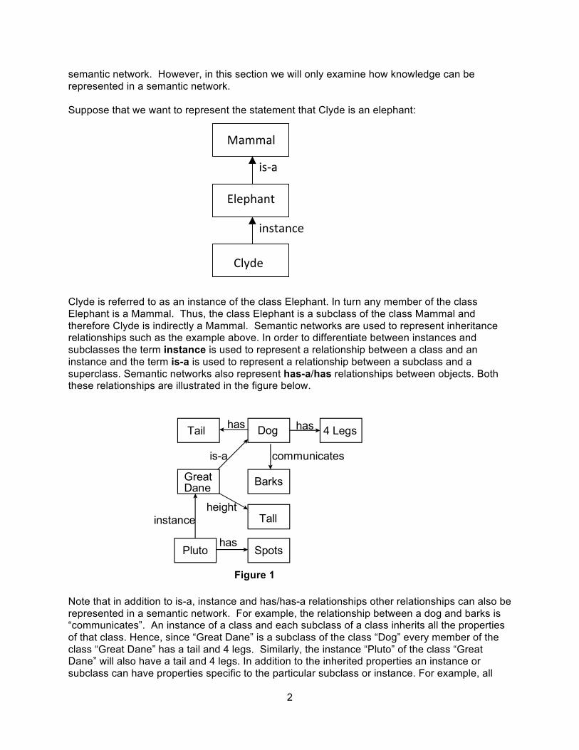
semantic network. However, in this section we will only examine how knowledge can be represented in a semantic network. Suppose that we want to represent the statement that Clyde is an elephant: Clyde is referred to as an instance of the class Elephant. In turn any member of the class Elephant is a Mammal. Thus, the class Elephant is a subclass of the class Mammal and therefore Clyde is indirectly a Mammal. Semantic networks are used to represent inheritance relationships such as the example above. In order to differentiate between instances and subclasses the term instance is used to represent a relationship between a class and an instance and the term is-a is used to represent a relationship between a subclass and a superclass. Semantic networks also represent has-a/has relationships between objects. Both these relationships are illustrated in the figure below. Note that in addition to is-a, instance and has/has-a relationships other relationships can also be represented in a semantic network. For example, the relationship between a dog and barks is “communicates”. An instance of a class and each subclass of a class inherits all the properties of that class. Hence, since “Great Dane” is a subclass of the class “Dog” every member of the class “Great Dane” has a tail and 4 legs. Similarly, the instance “Pluto” of the class “Great Dane” will also have a tail and 4 legs. In addition to the inherited properties an instance or subclass can have properties specific to the particular subclass or instance. For example, all
Mammal
Elephant
Clyde
is-‐a
instance
Tail Dog 4 Legs
GreatDane Barks
Tall
Pluto Spots
has has
is-a communicates
heightinstance
has
Figure 1

3
great danes are tall. The instance “Pluto” has spots in addition to possessing all the other properties of great danes. More examples of semantic networks are illustrated below: Example 1
The semantic network in Figure 2 represents a number of relationships. For example, a “Person” is a “Mammal”. “Pee-Wee-Reese” is an instance of the class “Person”. Pee-Wee-Reese is on the team “Broklyn-Dodgers”. The instance relationship identifies “Pee-Wee-Reese” as a “Person” and a “Person” as a “Mammal”. From this semantic network we can infer that “Pee-Wee-Reese” must have a “Nose” since “Pee-Wee-Reese” is a person. Example 2 John’s height is 72. John is taller than Bill.
Example 3 Thus, far we have examined binary relationships, i.e. relationships between at most two objects. However, it may be necessary to represent n-ary (n >2) relationships using a semantic network.
Mammal
Person Nose
Pee-Wee BrooklynBlue Reese Dodgers
is-a
has-a
instance
teamuniformcolour
Figure 2
John 72height
Figure 3
John
H1
Bill
H2
height height
greaterthan
Figure 4

4
In this case the n-ary relationship must be converted into a number of binary relationships. Suppose that we want to represent the fact that “John gives Mary the book”, i.e. give(john, mary, book32). This relationship involves three objects. The relationship is broken down into a number of binary relationships as indicated in Figure 5. A number of problems were experienced with using semantic networks to represent knowledge. Firstly, the relationships that can be represented using a semantic network are very general and unstructured. Thus, semantic networks cannot be used to represent complex domains. Attempts were made to standardize the relationships that could be represented in a semantic network and so possibly alleviate some of the problems. The development of a verb-oriented approach was one of the results of these endeavors. This approach defines the following case relationships: agent, object, instrument, location and time. Every sentence is represented using a case frame. A case frame represents a particular action and basically consists of arcs linking nodes representing different participants involved in an action. Figure 6 represents the corresponding semantic net using this approach to represent the statement: Sarah fixed the chair with glue. Exercise 1 Construct a semantic network to represent each of the following statements: 1. Pompeian(Marcus), Blacksmith(Marcus).
Give
Book32
recipient
object
giverMary John
Figure 5
glue
Fix
instrument
time
objectagentSarah
past
chair
Figure 6

5
2. Mary gave the green coloured vase to her favorite coursin. 3. John went downtown to deposit his money in a bank. 2.2. Conceptual Graphs A conceptual graph is a connected bipartite graph. Conceptual relation nodes represent relations between concepts. Thus, the arcs connecting nodes are not labeled. This is one of the main differences between conceptual graphs and semantic networks. A conceptual graph consists of concepts, represented by boxes and conceptual relations are represented by ellipses. Concept nodes only have arcs to conceptual relation nodes (thus the graph is bipartite). Concept nodes represent concrete objects, e.g. cat, telephone, restaurant, etc, and abstract objects, e.g. love, beauty and loyalty. In order to represent a relation of arity of n a conceptual relation node must have n arcs. Let us look at some examples to make this clearer. 1-ary relation 2-ary relation
3-ary relation
Let us look at a more detailed example. Suppose that we want to represent the relation that Mary gave John the book. The corresponding conceptual graph is illustrated below:
bird flies
dog colour brown
Maryagent
agent
give object
book
person:
person:John
child parents
mother
father

6
Notice that each concept node represents an individual and specifies the type of the individual. If an individual object is unknown a unique marker can be used in place of the name of the object. A unique marker is comprised of a hash symbol (#) followed by a number. Each object has its own unique marker. In the first conceptual graph in Figure 7 the name of the dog is known. However, in the second conceptual graph it is not known and a unique marker is used for this purpose. The first conceptual graph in Figure 7 is equivalent to the conceptual graph in Figure 8.
Note that when individuals of a particular type appear on their own (i.e. without the type specified before the individual name) the name of the individual must appear in inverted commas, e.g. “emma”.
Example 1
Suppose that we want to represent the following information using a conceptual graph:
Her name was McGill and she called herself Lil, but everyone knew her as Nancy.
Emmacolour brown dog:
#1352colour brown dog:
Figure 7
name ”emma”
#1352colour brown dog:
Figure 8
name ”Nancy”
#941name
“McGill”
person: name
“Lil”

7
In addition to individual markers conceptual nodes can also contain generic markers. A generic marker is represented by an asterisk *. A generic marker is used to represent an unspecified individual of a type. The type dog specified in a node is equivalent dog:*. Name variables can also be used, e.g., *X to indicate an unspecified individual. Let us look at an example of this. Suppose that we want to represent the following information:
The dog is scratching its ear with its paw.
We need to indicate that the paw and ear belong to the same dog. We can use name variables for this purpose. This is illustrated below:
The format that we have used thus far to represent conceptual graphs is referred to as the Display Form (DF). An alternative notation is the Linear Form (LF) which is a more compact notation. Suppose that we wanted to represent the following statement:
John is going to Boston by bus.
The conceptual graph in DF notation:
objectagent scratch
instrument
dog: *X
paw
ear
dog: *X
part
part
agentperson:John go destination
city:Boston
instance
bus

8
The conceptual graph in LF notation: [Go] – (Agnt) → [Person: John] (Dest) → [City: Boston] (Inst) → [Bus] Exercise 2 Translate each of the following sentences into a conceptual graph: 1. Jane gave Tom an ice cream. 2. Basketball players are tall. 3. Paul cut down the tree with an axe. 4. Place all the ingredients in a bowl and mix thoroughly. 3. Logical Representation Scheme We are only going to look at one logical representation scheme, namely, first-order predicate logic. Predicate logic is more powerful than propositional logic as it allows for quantification. Facts are represented as logical propositions and additional information is deduced from these facts using backward chaining or resolution. 3.1 Converting facts to logical propositions The first step is to convert facts in English to logical propositions called well-formed formulas (wffs). The wffs include the following symbols:
• Implies: → • And: /\ • Or: \/ • Not: ~ • For all: ∀ • The exists: ∃
Example: Consider the following facts on Italian history:
1. Marcus was a man. 2. Marcus was a Pompeian. 3. All Pompeians were Roman. 4. Caesar was a ruler. 5. All Romans were either loyal to Caesar or hated him. 6. Everyone is loyal to someone. 7. People only try to assassinate rulers that they are not loyal to. 8. Marcus tried to assassinate Caesar. 9. All men are people.
These facts can be represented in predicate logic as the following wffs:

9
1. man(Marcus) 2. Pompeian(Marcus) 3. ∀x: Pompeian(x) → Roman(x) 4. ruler(Caesar) 5. ∀x: Roman(x) → loyalto(x,Caesar) \/ hate(x,Caesar) 6. ∀x ∃y: loyalto(x,y) 7. ∀x ∀y: person(x) /\ ruler(y) /\ tryassassinate(x,y) → ~loyalto(x,y) 8. tryassassinate(Marcus,Caesar) 9. ∀x: man(x) → person(x)
3.2. Backward Chaining Suppose that given the facts 1 to 9 in the previous section, we want to answer the question ‘Was Marcus loyal to Caesar”? We can prove this using backward chaining. Backward chaining matches a clause to the right-hand side of a rule (wff with an implies) and then attempts to prove the clauses on the left-hand of the rule. Alternatively, a clause can be matched against a single clause. Since wff 7 has a ~loyalto on the right-hand side we will attempt to prove ~loyalto(Marcus, Caesar): ~loyalto(Marcus, Caesar) ↓ 7 person(Marcus) /\ ruler(Caesar) /\ tryassasinate(Marcus,Caesar) ↓ 8 person(Marcus) /\ ruler(Caesar) ↓ 4 person(Marcus) ↓ 9 man(Marcus) ↓ 1 Nil Using backward chaining we have proved that Marcus is not loyal to Caesar. Exercise 3 1. Consider the following facts:
1. John likes all kinds of food. 2. Apples are food. 3. Chicken is food 4. Anything anyone eats and is not killed by is food. 5. Bill eats peanuts and is still alive. 6. Sue eats everything Bill eats.
a) Convert these facts to wffs in predicate logic. b) Using backward chaining prove the “John likes peanuts”.

10
2. Consider the following facts:
1. Steve only likes easy courses. 2. Science courses are hard. 3. All the courses in the basketweaving department are easy. 4. BK301 is a basketweaving course.
a) Convert these facts to wffs in predicate logic. b) Use backward chaining to answer the question “What course would Steve like?”.
3.3 Computable Functions and Predicates It may be necessary to compute functions as part of a fact. In these cases a computable predicate is used. A computable predicate may include computable functions such as +, -, *, etc. For example, gt(x-y,10) →bigger(x) contains the computable predicate gt which performs the greater than function. Note that this computable predicate uses the computable function subtraction. Example: Consider the following statements:
1. Marcus was a man. 2. Marcus was Pompeian. 3. Marcus was born in 40 A.D. 4. All men are mortal. 5. All Pompeians died when the volcano erupted in 79 A.D. 6. No mortal lives longer than 150 years. 7. It is now 1991. 8. Alive means not dead. 9. If someone dies, he is dead at all later times.
The wffs for these facts are:
1. man(Marcus) 2. Pompeian(Marcus) 3. born(Marcus,40) 4. ∀x: man(x) → mortal(x) 5. erupted(volcano,79) /\ ∀x: Pompeian(x) → died(x,79) 6. ∀x ∀t1 ∀t2: mortal(x) /\ born(x,t1) /\ gt(t2-t1,150) → dead(x,t2) 7. now=1991 8. ∀x ∀t: [alive(x,t) → ~dead(x,t)] /\ [~dead(x,t) →alive(x,t)] 9. ∀x ∀t1 ∀t2:died(x,t1) /\ gt(t2,t1) →dead(x,t2)
Suppose we want to answer the question “Is Marcus alive now?”. We can do this by either proving alive(Marcus,now) or ~alive(Marcus,now). Let us try the latter:

11
~alive(Marcus,now) ↓ 8 ~[~dead(Marcus,now)] ↓ negation operation dead(Marcus,now) ↓ 9 died(Marcus,t1) /\ gt(now,t1) ↓ 5 erupted(volcano,79) /\ Pompeian(Marcus) /\ gt(now,79) ↓fact, 2 gt(now,79) ↓ gt(1991,79) ↓ compute gt
nil 3.4 Resolution In the previous sections facts were proved or queries were answered using backward chaining. In this section we will examine the use of resolution for this purpose. Resolution proves facts and answers queries by refutation. This involves assuming the fact/query is untrue and reaching a contradiction which indicates that the opposite must be true. The wffs must firstly be firstly converted to clause form before using resolution. The algorithm for converting wffs to clause form and the resolution algorithm are listed below. Algorithm: Converting wffs to Clause Form
1. Remove all implies, i.e. → by applying the following: a → b is equivalent to ~a \/ b.
2. Use the following rules to reduce the scope of each negation operator to a single term: • ~(~a) = a • ~(a /\ b) = ~a \/ ~b • ~(a \/ b) = ~a /\ ~b • ~∀x: p(x) = ∃x: ~p(x) • ~∃x: p(x) = ∀x: ~p(x)
3. Each quantifier must be linked to a unique variable. For example, consider ∀x: p(x) \/
∀x: q(x). In this both quantifiers are using the same variable and one must changed to another variable: ∀x: p(x) \/ ∀y: q(y).
4. Move all quantifiers, in order, to the left of each wff.
5. Remove existential quantifiers by using Skolem constants or functions. For example, ∃x: p(x) becomes p(s1) and ∀x ∃y: q(x,y) is replaced with ∀x: q(s2(x), x).
6. Drop the quantifier prefix.
7. Apply the associative property of disjunctions: a \/ (b \/ c) = (a \/ b) \/ c and remove brackets giving a \/ b \/ c.

12
8. Remove all disjunctions of conjunctions from predicates, i.e. create conjunctions of disjunctions instead, by applying the following rule iteratively: (a /\ b) \/ c = (a \/ c) /\ (b \/ c).
9. Create a separate clause for each conjunction.
10. Rename variables in the clauses resulting from step 9. to ensure that no two clauses refer to the same variable.
Algorithm: Resolution
1. Convert the wffs to clause form.
2. Add the fact (or query) P to be proved to the set of clauses: i. Negate P. ii. Convert negated P to clause form. iii. Add the result of ii to the set of clauses.
3. Repeat
i. Select two clauses. ii. Resolve the clauses using unification. iii. If the resolvent clause is the empty clause, then a contradiction has been
reached. If not add the resolvent to the set of clauses.
Until (a contradiction is found OR no progress can be made) Consider the following wffs:
1. man(Marcus) 2. Pompeian(Marcus) 3. ∀x: Pompeian(x) → Roman(x) 4. ruler(Caesar) 5. ∀x: Roman(x) → loyalto(x,Caesar) \/ hate(x,Caesar) 6. ∀x ∃y: loyalto(x,y) 7. ∀x ∀y: person(x) /\ ruler(y) /\ tryassassinate(x,y) → ~loyalto(x,y) 8. tryassassinate(Marcus,Caesar) 9. ∀x: man(x) → person(x)
Converting these to clause form gives:
1. man(Marcus) 2. Pompeian(Marcus) 3. ~Pompeian(x) \/ Roman(x) 4. ruler(Caesar) 5. ~Roman(x1) \/ loyalto(x1,Caesar) \/ hate(x1,Caesar) 6. loyalto(x2,s1(x2)) 7. ~person(x3) \/ ~ruler(y) \/ ~tryassassinate(x3,y) \/ ~loyalto(x3,y) 8. tryassassinate(Marcus, Caesar) 9. ~man(x4) \/ person(x4)

13
Suppose that we want to prove that Marcus hates Caesar. We firstly convert this to a wff: hate(Marcus,Caesar). The wff is then negated and converted to clause form: ~hate(Marcus,Caesar). This clause is added to the set of clauses and the resolution is algorithm is applied: ~hate(Marcus,Caesar) ↓ 5 ~Roman(Marcus) \/ loyalto(x1,Caesar) ↓ 3 ~Pompeian(Marcus) \/ loyalto(Marcus,Caesar) ↓ 2 loyalto(Marcus,Caesar) ↓ 7 ~person(Marcus) \/ ~ruler(Caesar) \/ ~tryassassinate(Marcus,Caesar) ↓ 4 ~person(Marcus) \/ ~tryassassinate(Marcus,Caesar) ↓ 8 ~person(Marcus) ↓ 9 ~man(Marcus) ↓ 1 □
Thus, we have a contradiction and the original statement, i.e. Marcus hates Caesar must be true. Consider the wffs we created above:
1. man(Marcus) 2. Pompeian(Marcus) 3. born(Marcus,40) 4. ∀x: man(x) → mortal(x) 5. erupted(volcano,79) /\ ∀x: Pompeian(x) → died(x,79) 6. ∀x ∀t1 ∀t2: mortal(x) /\ born(x,t1) /\ gt(t2-t1,150) → dead(x,t2) 7. now=1991 8. ∀x ∀t: [alive(x,t) → ~dead(x,t)] /\ [~dead(x,t) →alive(x,t)] 9. ∀x ∀t1 ∀t2:died(x,t1) /\ gt(t2,t1) →dead(x,t2)
Suppose we now want to use resolution to prove that “Marcus is not alive now”. We firstly have to convert these statements to clause form:
1. man(Marcus) 2. Pompeian(Marcus) 3. born(Marcus,40) 4. ~man(x) \/ mortal(x) 5. erupted(volcano,79) 6. ~Pompeian(x1) \/ died(x1,79) 7. ~mortal(x2) \/ ~born(x2,t1) \/ ~gt(t2-t1,150) \/ dead(x2,t2) 8. now=1991 9. ~alive(x3,t) \/ ~dead(x3,t) 10. dead(x4,t3) \/ alive(x4,t3)

14
11. ~died(x5,t4) \/ ~gt(t5,t4) \/ dead(x5,t5) We want to prove ~alive(Marcus,now). We negate this and convert it clause form: alive(Marcus, now) and find a contradication: alive(Marcus,now) ↓10 dead(Marcus,now) ↓11 ~died(Marcus,t4) \/~gt(now,t4) ↓6 ~Pompeian(Marcus) \/~gt(now,79) ↓ 2 ~gt(now,t4) ↓8 ~gt (1991,79) ↓ □
Exercise 4 1. Consider the following facts:
1. John likes all kinds of food. 2. Apples are food. 3. Chicken is food 4. Anything anyone eats and is not killed by is food. 5. Bill eats peanuts and is still alive. 6. Sue eats everything Bill eats.
a) Convert the wffs for these facts (which you created in Exercise 3) to clause form. b) Using resolution prove that “John likes peanuts”.
2. Consider the following facts:
1. Steve only likes easy courses. 2. Science courses are hard. 3. All the courses in the basketweaving department are easy. 4. BK301 is a basketweaving course.
a) Convert the wffs for these facts (which you created in Exercise 3) to clause form. b) Use resolution to answer the question “What course would Steve like?”.