knowledge base - concrete product machines and solutions
TRANSCRIPT

Knowledge Base
Article Type: Instructions
Mold Assembly for Models,
10, 12, 16, 22HF, 16HF, and 1600
WARNING Never work on, clean or service this unit, control panel or any machine or open or remove any protective cover, guard, grate, door, or maintenance panel until the power or energy sources has been turned off, locked out / tagged out, and all moving parts have come to a complete stop and or blocked to prevent movement. Machinery is dangerous – avoid personal injury and or death by following manufacture, Local, and OHSA safety procedures. Contact Columbia Machine for safety decals, guards, horns and beacons.
Description:
Instructions on “How to” properly assemble, clean and inspect, repair and
rework molds, and proper mold care.

&ROXPELDColumbia Machine Inc.107 Grand BoulevardVancouver, Washington 98668
RecommendedProcedure forMold Assembly
Model 10ACthrough Model1600
��� �� � �� ��� � � �� � �� � �

Table of ContentsIntroduction………………………………...Page 2
“How to” Manual to help in assembling Molds for
�� ��� ��� ConcreteProducts Machine.
Recommended Tools Overview…………..Page 3Fixtures - Working surface-Tools - Wrenches-Gauges -AccuracyChecking
Recommended Tools……………………..Page 4Working Surface for Assembling
Recommended Tools …………………….Page 5Mold Gauges ……………………………...Page 7
Corebar Assembly Alignment
Mold Gauges……………………………... Page 8Compression Shoe Setup Gauge
Regular Mold Care ……………………….Page 9Mold Repair………………………………..Page 10
Welding and repair of hardened surfaces…..
Clean and inspect all parts prior to assembling mold.Checking for excessive wear.…………………... Page 11
Clean and inspect all parts prior to assembling mold.End Plate / SetScrew Replacement…………….Page 12
Clean and inspect all parts prior to assembling mold.Mounting Bracket Die Support Inspection……...Page 13
Clean and inspect all parts prior to assembling mold.Compression Shoe Inspection…………………..Page 14
Clean and inspect all parts prior to assembling mold.Head Plunger Inspection………………………….Page 15
Clean and inspect all parts prior to assembling mold.Corebar Assembly Inspection…………………...Page 16
Mold Box Assembly Overview……………...Page 17Torque Specifications- Step by Step Assembly of Mold Box- Quality Checking toInsure alignment-Head Assembly- Mold Alignment
Mold Box Assembly Torque Specifications overview...Page 182-3 Block Molds Model 10AC, 21, 22, Mod 12, 12AC, 16, 20
4 Block Molds Model 1600
Torque Specifications -General……………..Page 192-3 Block Imperial Torque Recommendations Sheet..….Page 202-3 Block Metric Torque Recommendations Sheet. . .….Page 214 Block Imperial Torque Recommendations Sheet. .….Page 224 Block Metric Torque Recommendations Sheet…... ….Page 23
Mold Box Assembly……………………….….Page 24Mounting Bracket alignment on Mold Box……...….Page 29Mounting Bracket height adjustment specification
……………………………………………………... ….Page 30Cavity Adjustment process……………………….….Page 31Corebar Assembly Alignment in mold cavity …. ….Page 35Compression Shoe to Head Plunger Alignment….Page 36Head Assembly to mold cavity alignment …….. ….Page 38
Mold Assembly Alignment………………..….Page 39Mold Assembly Conclusion……………... ….Page 41
Final Torqueing of all fasteners-rechecking for proper alignment

2
Introduction“How to” Manual to help inassembling Molds for ColumbiaConcrete Products Machine.
Prolonging Mold Wear Life of&ROXPELD Molds.
For Model 2-Block molds (10AC, 21, & 22)For Model 3-Block molds (12AB, 12AC, 16, 20)For Model 4-Block molds (1600)

3
Recommended Tools
■ Fixtures - Working surface■ Tools - Wrenches■ Gauges■ Accuracy Checking

4
Recommended Tools Working Surface for Assembling
■ Locate a flat surface upon which torebuild the mold. If the bottom of themold is not assembled on a flatsurface, the mold will not be builtsquare. Therefore the pallet, duringmachine operation, will contact themold unevenly, causing poor blockquality and premature mold wear.✦ There is also potential machine
vibrator bearing failure due to non-parallel mold- mounting brackets.

5
&ROXPELD recommends a sturdy table with aremovable top plate, which can be regroundas the surface deteriorates due to wear.
&ROXPELD partnumber 405.32.1(assembly table &surface heightgauge-verniercalipers)

6
Recommended Tools cont.■ 4” Steel Wedges (for usage see page 28)
■ Brass Hammer (Soft headed)■ Vernier Dial Calipers-Surface height
gauge (for usage see page 29)
■ 10” Machinist Square (for usage see page 32)
■ Torque Wrench (range to 500 foot-pounds)
■ Miscellaneous Wrenches appropriate foreach bolt size (socket head, hex head, flat headcapscrews)
■ Replacement supply of grade5 & grade8bolts, nuts, nylon insert locknuts, lockwashers,setscrews, (see Mold Torque SpecificationsSheets)
■ Thread locking compound, such as “Loctite#262” to be used on torqued bolts

7
Mold Gaugesfor Corebar Assembly alignment
Corebar Assembly GaugesPart #’s607002.01.00 1”607002.01.13 1-1/8”607002.01.25 1-1/4”607002.01.50 1-1/2”607002.01.75 1-3/4”
1” 1-1/8” 1-1/4”
1-1/2” 1-3/4”
See Page 35 for usage

8
Mold Gauges cont.
■ Optional Compression Shoe SetupGauge
Shoe Alignment GaugesPart Number Dim A CPM604899 3.625 12C/16604899.A 3.625 1600604636 5.625 12C/16604636.A 5.625 1600603823 7.625 12C/16603823.A 7.625 1600
A

9
Regular Mold Care■ After production, thoroughly clean all
mold wear surfaces of any concretematerials and apply oil to the wear partsprior to storage. (Cement is a caustic that candeteriorate even hardened steel)
■ Coating the wear parts with oil beforestorage will protect their hardened wearsurface from oxidation and pitting. Acause of premature mold life.
■ Inspect parts for cracks and/or wear andreplace before storage.

10
Mold Repair and Rework■ Welding Mold Wear Parts
◆ Insure good heat isolation to surrounding area✦ Surface Hardness is effected at temperature starting at 250 degrees✦ Immersion in water✦ repeated small incremental welds with quenching to cool between each step
◆ Welding rod recommendation:✦ Low Hydrogen based welding rod for general welding✦ E4130 (rod used for welding SAE 4130 type Tool Steel)
• For small spot repairs
✦ Hard surfacing rod
■ Welding Non Wear Surfaces◆ Low Hydrogen based welding rod
✦ For welding Corebar Clips onto Corebar Assemblys✦ For Welding Cores onto Corebar Assemblies✦ General welding and patching
◆ Cores should be welded to Corebar (T-1 Spring steel) using 4 passes, 2 per side of the corebar,starting from outside edge of core and stopping at the middle of the core.
■ Drill and Tap Rework◆ Non wear parts can be reworked in a typical manner for mild steel
◆ Hardened wear parts have same characteristics as tools used to drill and tap, requiring carbidetools
✦ Soften area utilizing heat and then slow cooling Note: This will reduce mold wear life✦ Grind through case in area to be reworked

11
Clean and inspect all parts prior toassembling mold.
■ Check for excessive wear on allsurfaces, including gouges and scoredsurfaces (0.025” depth or greater,consider replacement).
■ Radiused edges on the bottom (palletside) of end liners, partition plates, cores,etc., cause feathered edges on the palletside of the block.Tip: Outside partition plates can berotated 180 degrees C.
■ Check tapped holes for clean completethreads.

12
Clean and inspect all partsprior to assembling mold. cont.
■ Replace self locking(nylon insert)setscrewsin end plates.(area of end plateunder the top tab ofpartition plates).
■ See Page 34 for properadjustment
Note: The partition plates and end plates will prematurely fail during operation ifthe operator/assembler fails to keep the setscrews tight.

13
Clean and inspect all partsprior to assembling mold. cont.
MountingBracket DieSupportmountingsurfaces shouldbe clean, flat,free of paint orforeign material,and parallel.Mounting holesshould not beelongated orcracked.
Tip: Also check condition of the machine die supports.The mating surfaces should be flat, parallel, and square.

14
Clean and inspect all partsprior to assembling mold. cont.■ Compression
shoes should beflat and straightand have cleansharp edges(rounded edgeswill createfeathered edgeson the tops of theproduct).Tip: In MostCases, Shoes canbe flipped 180degrees for addedwear life. C

15
Clean and inspect all parts priorto assembling mold. cont.
■ Headplungerlegsshould bestraightand thebottom(shoe side)should beflat.

16
Clean and inspect all partsprior to assembling mold. cont.
■ Inspect theCorebarAssemblybottomside witha straightedge toinsure bottomsare straight andflat.
■ Check plungerpin to see that itoperatessmoothly andthere is nothinginterfering withventing whileproducing block.
&ROXPELD spring part no. 6344
Check for wear on theplunger pin - That the venthole is closed when the pinis flush with the bottom of thecore.
&ROXPELD Plunger pin
part no. 601159
17
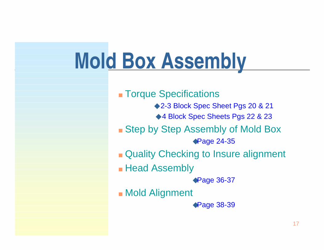
Mold Box Assembly■ Torque Specifications
◆ 2-3 Block Spec Sheet Pgs 20 & 21◆ 4 Block Spec Sheets Pgs 22 & 23
■ Step by Step Assembly of Mold Box◆Page 24-35
■ Quality Checking to Insure alignment■ Head Assembly
◆Page 36-37
■ Mold Alignment◆Page 38-39

18
Mold Box Assembly Torque Specifications
■ 2-3 Block MoldsModel 10AC, 21, 22, Mod 12, 12AC, 16, 20
■ 4 Block MoldsModel 1600

19
Torque Specifications■ Torque specifications are for comparative
purposes only. All bolts of similar size andfunction should be tightened to the same torque.Hex and socket head capscrews used should beSAE grade 8 (or metric equivalent) on the moldbox and shoes, SAE grade 5 (or metricequivalent) or better on corebar assemblies andhead plungers. Because the mold assemblyvibrates during operation, even properly torquedbolts can loosen and regular checking to insureproper tightness is recommended. (See moldassembly torque drawing pages)
■ &ROXPELD encourages using a thread-locking
compound, such as “Loctite #262” on torquedbolts.

20
2-3 Block Imperial Torque Recommendations

21
2-3 Block Metric Torque Recommendations

22
4 Block Imperial Torque Recommendations

23
4 Block Metric Torque Recommendations

24
Mold Box AssemblyLift one of theend plates, andposition the firstpartition plate.Sliding one end ofthe interior (inside)partition plates intothe end platenotches.
Optional aid is touse spacer blocks-1” high spacers for8-high molds.3/8” spacers for4-high molds.

25
Mold Box Assembly■ Position the
remaining endplate on theopposite end ofthe insidepartition plates.
■ Locate thedrilled (outside)partition platesto the left andright sides ofthe end platesand themountingbrackets.Securing withone bolt at eachcorner of thebox.

26
Mold Box Assembly■ Set the end
liners into thecavities andinstall allfastenersusing locktitethread lockingcompound.Use highcollar lockwashers toensurecorrect threaddepth.

27
Mold Box Assembly
■ Threadtheremainingmountingbracketbolts andtighten toapproximately 5 ft-lbs (6 Nm)

28
Mold Box Assembly ■ Place two wedgesunder onemounting bracket,one under eachside. Use thewedges to lift themounting bracketonly, do no lift themold off the table.Tighten the boltsto a snug fit, youonly want to holdthe brackets inplace, and youwill need to adjustthem later.Repeat this stepon the othermounting bracket.

29
Mold Box AssemblyMounting Bracket alignment on mold■ Set the height
from the bottom ofthe mold (flatsurface in whichthe mold is beingassembled on) tothe top of themounting bracketdie supportsurface to within0.005" using amallet and heightgauge (vernier dialcalipers).

30
Mold Box AssemblyMounting Bracket Height Adjustment Specification
For Model 10AC, 21, & 22 the height of thedie support surface to the bottom of the moldis determined by subtracting 2.687” from theoverall height of the mold box. (i.e. 7.875” - 2.687” = 5.187”)
For Model 12AC, 16, & 1600 the height ofthe die support surface to the bottom of themold is determined by subtracting 1.687”from the overall height of the mold box.(i.e. 7.875” - 1.687” = 6.187”)
2-Block Molds Model 10AC, 21, & 223&4-Block Molds Model 12AB, 12AC, 16,20, & 1600

31
Mold Box AssemblyCavity Adjustment Process
■ Measure thecavity lengthat the top ofthe Mold.
&ROXPELD
assembliesthe cavity to1/32" underthe modularblock length.

32
Mold Box AssemblyCavity Adjustment Process
■ Use aMachinist’ssquare to checkfor draft on thecavity ends.Place thesquare insidethe block cavityon the surfacethat the mold isbeing built onand slide theupright end ofthe square upagainst the endliner.
A slight positive draft (light shining through near the bottom up to 1/64" per end) isacceptable and aids in stripping the product and reducing mold wear. Avoid Negative Draft!Adjust the draft using a soft headed mallet prior to fully tightening the mntg bracket bolts.

33
Mold Box Assembly■ Double check the
measurements ofthe cavity, length,draft, andmounting bracketheight.
■ Torque allmounting bracketbolts to 120 ft.-lbs.when the heightmeasurementsare correct.

34
Mold Box Assembly■ With the cavity length
and end draft adjusted,tighten the self lockingsetscrews (see pg 12)which lock the partitionplates. These arelocated on theunderside of the endplate top flange.
Note: The partitionplates and end plateswill prematurely failduring operation if theoperator/assemblerfails to keep thesetscrews tight.

35
Mold Box AssemblyCorebar Assembly Alignment in Mold Cavity
■ Block up the moldbox to approximately1” off assemblysurface, and Installthe corebarassemblies. Ensurethat lock washers andlock nuts are used onall corebar assemblymounting bolts. Donot tighten thecorebar assemblyfasteners.
■ Utilizing alignmentgauges to set thewalls and end webs,position the corebarassemblies to thecorrect alignmentwithin the cavities andtighten fasteners toproper torque. Reference Page 7 for correct gauges

36
Mold Box Assembly Compression Shoe to Head Plunger Alignment
■ Set One head plungeronto the table shoe sideup. Bolt the shoes to headPlungers using lockwashers and Nylon Insertlock nuts. Maintain a 3/8 toa 9/16" gap between theshoes; (depending on thestyle of blockmanufactured – 9/16” isthe standard for basicConcrete Masonry Units).
■ This should give a 1/32"clearance on each side(between shoe andpartition plate) when theshoes enter the mold box.
■ Make sure both shoes areparallel and square.
■ Set the shoes to 1/32" perside (1/16” total) under theblock width. Square ends,and tighten to 44-ft. lbs.
9/16”

37
Mold Box Assembly Compression Shoe to Head PlungerAlignment
■ OptionalCompression ShoeSetup Gauge
■ Assemble Head Plungersonto the Head Platesnugging the bolts tight butnot torqueing at this time.
■ Assemble the Compressionshoes onto the HeadPlungers with boltstightened finger tight.
■ With the Head Assemblypositioned upside down,(compression shoes up, asshown)place the ShoeSetup Gauge onto theshoes, moving the shoesuntil all fit into the gaugecavities.
■ Tighten shoe and HeadPlunger bolts to torquespecifications and removethe gauge. (page 20-23)

38
Mold Box Assembly Head Assembly to Mold Cavity Alignment
■ Set the mold box inthe mold alignmentfixture or BlockMachine.
■ Place each headplunger/shoeassembly into theirrespective cavities,centering them.Ensure that a 1/32"clearance existsbetween the shoesand the partitionplates. Place the headplate on top the headplungers and insertbolts (placing lockwashers on the bolts).Do not tighten thebolts to full tension.This allowsadjustment from sideto side.

39
Mold Assembly Alignment
■ Bring Machinecompressionbeam, or upperbeam of MoldAlignmentFixture, downuntil it contactsthe headassembly andbolt headassembly tocompressionbeam.
(Mold is shown in Mold Alignment Fixture)

40
Mold Assembly Alignment■ Cycle the head
assembly in and outof the mold box tocheck for proper fit.Cycle it slowly thefirst few times just incase the shoes arenot lined upcorrectly. Whencycling the headassembly up anddown, listen for anysqueaks or clicks.Note their locationsand adjust the headplungers or shoesfor clearance. (Mold is shown in Mold Alignment Fixture)

41
Mold Box AssemblyConclusion
■ When you are donetesting the mold, Torque the head
bolts to proper specifications and
re-check for Proper clearances.
■The Mold Is NowReady ForProduction