kni416 mm - НЕБО-Сервис · b kni 416 revision 4, february/2006 15661m04 page rh-1...
TRANSCRIPT

MAINTENANCE MANUAL
KNI 416
RADAR ALTIMETERINDICATOR
MANUAL NUMBER 006-15661-0004Revision 4, February 2006

THIS PUBLICATION MAY BE CONTROLLED BY THE U.S. DEPARTMENT OF STATE INTER-NATIONAL TRAFFIC IN ARMS REGULATIONS (ITAR) 22 CFR 120-130 OR THE U.S.DEPARTMENT OF COMMERCE EXPORT ADMINISTRATION REGULATIONS (EAR), ANDMAY NOT BE EXPORTED OUT OF THE UNITED STATE OR BE PROVIDED TO FOREIGNPERSONS (AS DEFINED BY THE ITAR) LOCATED WITHIN THE UNITED STATES, WITHOUTTHE APPROPRIATE PRIOR AUTHORIZATIONS FROM THE U.S. GOVERNMENT. DIVER-SION CONTRARY TO U.S. EXPORT LAWS AND REGULATIONS IS PROHIBITED.
COPYRIGHT NOTICE
© 2004, 2005, 2006 HONEYWELL INTERNATIONAL INC.
REPRODUCTION OF THIS PUBLICATION OR ANY PORTION THEREOF BY ANY MEANS WITHOUT THE EXPRESS WRITTEN PERMISSION OF HONEYWELL IS PROHIBITED, EXCEPT TO THE EXTENT REQUIRED FOR INSTALLATION OR MAINTENANCE OF THE RECIPIENT'S EQUIPMENT. FOR FURTHER INFORMATION CONTACT THE MANAGER, TECHNICAL PUBLICATIONS, HONEYWELL, ONE TECHNOLOGY CENTER, 23500 WEST 105TH STREET, OLATHE, KS 66061 TELEPHONE: (913) 712-0400.

B KNI 416
REVISION HIGHLIGHTS
KNI 416
Maintenance Manual, Part Number: 006-15661-XXXX
For each revision, add, delete, or replace as indicated.
Revision 4, February/2006
All pages are fully revised and reformatted. Specific technical changes are denoted by revision bar.
Highlight(s) include the updating of the panel lamp tests.
ITEM ACTION
Full Reprint Replaces all previous revisions.
Revision 4, February/2006 15661M04 Page RH-1

B KNI 416
THIS PAGE IS RESERVED
Revision 4, February/2006 15661M04 Page RH-2

B KNI 416
TABLE OF CONTENTS
ITEM PAGE
SECTION IVTHEORY OF OPERATION
4.0 GENERAL...................................................................................................................... 4-1
4.1 SERVOED POINTER..................................................................................................... 4-1
4.2 DECISION HEIGHT (DH)............................................................................................... 4-2
4.3 SELF TEST.................................................................................................................... 4-2
4.4 FAILURE WARNING FLAG .......................................................................................... 4-3
SECTION VMAINTENANCE
5.1 GENERAL...................................................................................................................... 5-1
5.1.1 TEST EQUIPMENT........................................................................................................ 5-5
5.2 TEST AND TROUBLESHOOTING................................................................................ 5-7
5.2.1 KNI 416 TEST SET-UP AND TESTING (USING KRA 405) .......................................... 5-7
5.2.2 KNI 416 TEST SET-UP AND TESTING (USING KRA 405B) ...................................... 5-13
5.3 CALIBRATION AND ALIGNMENT ............................................................................. 5-19
5.3.1 CALIBRATION AND ALIGNMENT (USING KRA 405) ................................................ 5-19
5.3.2 CALIBRATION AND ALIGNMENT (USING KRA 405B) .............................................. 5-21
5.4 KNI 416 PERFORMANCE TEST................................................................................. 5-23
5.4.1 KNI 416 PERFORMANCE TEST (USING KRA 405)................................................... 5-23
5.4.2 KNI 416 PERFORMANCE TEST (USING KRA 405B) ................................................ 5-25
5.5 OVERHAUL................................................................................................................. 5-31
5.5.1 VISUAL INSPECTION ................................................................................................. 5-31
5.5.2 CLEANING................................................................................................................... 5-32
5.5.3 REPAIR........................................................................................................................ 5-37
5.6 DISASSEMBLY / ASSEMBLY PROCEDURES.......................................................... 5-41
5.6.1 DISASSEMBLY PROCEDURES ................................................................................. 5-41
5.6.2 ASSEMBLY PROCEDURES ....................................................................................... 5-43
SECTION VIILLUSTRATED PARTS LIST
6.1 GENERAL...................................................................................................................... 6-1
6.2 REVISION SERVICE ..................................................................................................... 6-1
6.3 LIST OF ABBREVIATIONS........................................................................................... 6-1
Revision 4, February/2006 15661M04 Page TC-1

B KNI 416
ITEM PAGE
6.4 SAMPLE PARTS LIST .................................................................................................. 6-3
6.5 KNI 416 FINAL ASSEMBLY ......................................................................................... 6-5
6.6 KNI 416 BEZEL ASSEMBLY ...................................................................................... 6-17
6.7 KNI 416 LIGHT BOARD.............................................................................................. 6-25
6.8 KNI 416 GEAR PLATE ASSEMBLY........................................................................... 6-31
6.9 KNI 416 MOTOR AND FILTER BOX .......................................................................... 6-43
6.10 KNI 416 FLAG MECHANICAL ASSEMBLY............................................................... 6-49
6.11 KNI 416 FLAG ASSEMBLY ........................................................................................ 6-53
6.12 KNI 416 SERVO AMPLIFIER...................................................................................... 6-57
6.13 KNI 416 RFI FILTER BOARD ..................................................................................... 6-67
6.14 KNI 416 RFI MOD BOARD.......................................................................................... 6-77
6.15 KNI 416 WIRING HARNESS....................................................................................... 6-81
Revision 4, February/2006 15661M04 Page TC-2

B KNI 416
ITEM PAGE
FIGURE 4-1 KRA 405 System Block Diagram.................................................................. 4-5FIGURE 5-1 Test Set-Up (Using KRA 405) ...................................................................... 5-9FIGURE 5-2 Test Set-Up (Using KRA 405B).................................................................. 5-14FIGURE 5-3 Fabricated Test Cable (Using KRA 405) .................................................... 5-45FIGURE 5-4 Fabricated Test Cable (Using KRA 405B).................................................. 5-47FIGURE 5-5 Troubleshooting Flow Chart ....................................................................... 5-49FIGURE 6-1 Sample Parts List ......................................................................................... 6-3FIGURE 6-2 KNI 416 Final Assembly ............................................................................... 6-9FIGURE 6-3 KNI 416 Final Assembly Schematic (-0001)............................................... 6-13FIGURE 6-4 KNI 416 Final Assembly Schematic (-0010)............................................... 6-15FIGURE 6-5 KNI 416 Bezel Assembly............................................................................ 6-21FIGURE 6-6 KNI 416 Light Board Assembly .................................................................. 6-27FIGURE 6-7 KNI 416 Gear Plate Assembly.................................................................... 6-35FIGURE 6-8 KNI 416 Motor & Filter Box Assembly ........................................................ 6-45FIGURE 6-9 KNI 416 Flag Mechanical Assembly........................................................... 6-51FIGURE 6-10 KNI 416 Flag Assembly.............................................................................. 6-55FIGURE 6-11 KNI 416 Servo Amplifier Assembly ............................................................ 6-63FIGURE 6-12 KNI 416 RFI Filter Board Assembly (-0001) ............................................... 6-71FIGURE 6-13 KNI 416 RFI Filter Board Assembly (-0010) ............................................... 6-73FIGURE 6-14 KNI 416 RFI Mod Board Assembly ............................................................ 6-79FIGURE 6-15 KNI 416 Wiring Harness Assembly ............................................................ 6-85
Revision 4, February/2006 15661M04 Page TC-3

B KNI 416
THIS PAGE IS RESERVED
Revision 4, February/2006 15661M04 Page TC-4

B KNI 416
ITEM PAGE
TABLE 5-1 Sub-Assembly Part Number Reference Chart ............................................. 5-1TABLE 5-2 Precision Outputs vs. Altitude and Signal Loop ........................................... 5-2TABLE 5-3 Required Test Equipment (Using KRA 405)................................................. 5-5TABLE 5-4 Required Test Equipment (Using KRA 405B) .............................................. 5-6TABLE 5-5 Recommended Cleaning Agents................................................................ 5-33TABLE 5-6 Unsafe Cleaning Agents............................................................................. 5-34
Revision 4, February/2006 15661M04 Page TC-5

B KNI 416
THIS PAGE IS RESERVED
Revision 4, February/2006 15661M04 Page TC-6

B KNI 416
SECTION IVTHEORY OF OPERATION
4.0 GENERALThe KNI 416 converts the Analog Altitude (Auxiliary Output #1) from the KRA 405/ KRA 405B Re-ceiver/ Transmitter to a visible indication of the aircraft altitude. The indicator consists of a fixed dial and servoed motor driven pointer.A Decision Height (DH) annunciator provides the pilot with a visual alarm when the selected DH is reached. The DH lamp may be turned off after it has come on by depressing the lamp once or turned back on by depressing the lamp a second time. The control logic ensures that the DH lamp will light when the aircraft descends through the decision height.The DH lamp is also photocell controlled so that the lamp does not blind the pilot during the critical stage of an approach if low ambient light conditions exist.Refer to FIGURE 4-1 KRA 405 System Block Diagram and the appropriate KNI 416 schematics. Refer to KRA 405 Maintenance Manual p/n 006-05104-00XX for radar altimeter system theory.The KNI 416 consists of the following major functions.
1. Servoed Pointer2. Decision Height (DH)3. Push-to-Test4. Failure Warning Flag
4.1 SERVOED POINTERThe servo-mechanism positions the pointer to the correct altitude by balancing the Analog Altitude (Auxiliary Output #1) and the voltage developed across precision reference R102 which is posi-tioned by the servoed motor. The input analog altitude is buffered by I301A, I301B, and Q301. Circuit I301B and Q301 provide a reference ground used to isolate the analog altitude from the indicator chassis ground.Circuit I204A and Q209 make up a Slope Amplifier that provides the 0 to 200 foot expanded scale.At altitudes below 200 feet (+4.4 volts) I204A acts as a non-inverting amplifier with a gain of 8.5. When the altitude reaches 200 feet (+4.4 volts) Q209 turns on reducing the gain to 1.6. R257 ad-justs the breakpoint in order to achieve optimum accuracy.The servo amplifier drive network, I210B, Q203, and Q204 differentially compares the analog al-titude to the reference voltage at TP209 determined by the position of R102.If the two voltages are unequal, a voltage is applied to the motor B101 that repositions R102 at a zero error position. The pointer then indicates an altitude corresponding to the analog altitude volt-age input to the indicator. Transistors Q203 and Q204 provide current drive to the motor. A float-ing voltage reference Q102, Q103, CR208, and CR209 is provided at the negative side of the mo-tor.This reference always maintains the negative terminal of the motor at one half the 27 volt filtered line (this voltage is unregulated and will vary from 21 to 32 volts), so that the positive and negative drive voltages to the motor will always be symmetrical. Transistors Q102 and Q103 provide a cur-rent sink for the motor.
Revision 4, February/2006 15661M04 Page 4-1

B KNI 416
4.2 DECISION HEIGHT (DH)The Decision Height preselected by the DH knob is the height at which the pilot must decide whether to land or not. When the DH is reached, the DH annunciator comes on, alerting the pilot of the predetermined altitude. The capability exists for the DH to be turned off after it lights by depressing the lens once or turned on again by depressing it a second time.Any time the DH bug is at an altitude lower than the aircraft altitude during descent, the light will come on as the aircraft descends through the DH. If the DH bug is set to greater than 50 feet, the self test function will turn the light on.I210A compares the buffered analog altitude to the voltage proportional to DH altitude set by R101. When the voltage at TP218 is less than the voltage at TP204, the output of the DH com-parator goes high, causing the DH light to turn on through inverters I202A and I202B.The lamp logic I202 and I203 is used to turn the lamp off once it has been turned on. When the DH button DS101B is depressed, the flip-flop I203A changes state, disabling I202B thus turning off Q201, the relay driver, extinguishing the DH lamp. Circuits I202C and I202D comprise a one-shot multivibrator used to debounce DS101B.The pulse output at TP205 is approximately 90 milliseconds. The DH Lamp can be turned on again by pressing the DH Lamp a second time, then the flip-flop changes state, returning control of Q201 to the DH comparator. The DH circuitry automatically rearms itself if the aircraft should ascend through the DH or if the DH bug should be reset below aircraft altitude.In either case, when the voltage at TP204 goes low, indicating the aircraft is above the DH setting, a logic 1 is applied to the reset input of I203A through CR207, causing the flip-flop to produce a logic 0 at the Q output returning control of Q201 to the DH comparator.The intensity of the DH lamp is controlled by the DH lamp dimmer, V101 and Q104. The resis-tance of photocell V101 is determined by ambient light conditions. The more ambient light avail-able, the smaller the resistance of V101 becomes, providing more voltage to DS101A through Q104 causing the lamp to be brighter. Similarly, the lamp is at minimum brightness in low ambient light conditions.The ground for the DH lamp is provided through a set of relay contacts of K201. Another set of contacts are provided so that external DH annunciate circuitry can be utilized.
4.3 SELF TESTThe self-test button functionally tests nearly the entire KRA 405 system, and initiates a complete self test for the KRA 405B. The calibration loop information is transferred to the signal loop for normal processing and displayed as if it were a true altitude. Self-test forces the failure warning systems, including the indicator flag. It also tests the DH if the DH bug is set greater than 50 feet, and provides a 50 foot altitude indication to the pilot. When the self-test button S101 is pushed the following occurs:
a. A ground is provided to initiate KRA 405/ KRA 405B self test circuits.b. Q208 is turned on, resetting flip-flop I203A.c. Q101 is turned on through CR213, placing the failure warning flag in view.
Revision 4, February/2006 15661M04 Page 4-2

B KNI 416
4.4 FAILURE WARNING FLAGThe failure warning indicator to the pilot is a bright red flag which alerts the pilot to possible fail-ures. Monitored inputs to the flag control circuit are as follows:
a. Servo ErrorThe servo error voltage output by I201B is monitored by the servo error detector I205A and I205B. Should the error exceed +/- 5 volts at TP212, indicating a servo malfunction, the voltage at TP213 goes high, turning off Q207.When Q207 turns off C204 discharges through R247, R248, and Q101 turning the relay drive Q101 off within 0.5 seconds after the servo error is detected bringing the flag DS107 into view.
b. +27.5 Vdc Aircraft PowerWhen aircraft power is lost, the flag comes into view since no power is available to drive DS107.
c. Self TestWhen the self test button is depressed, Q101 is turned off through CR213, causing the flag to come into view.
d. +30 VdcIf +30 Vdc power is lost, drive to Q101 is lost causing the flag to come into view.
Revision 4, February/2006 15661M04 Page 4-3

B KNI 416
THIS PAGE IS RESERVED
Revision 4, February/2006 15661M04 Page 4-4

B KNI 416
Revision 4, February/2006 15661M04 Page 4-5
FIGURE 4-1 KRA 405 System Block Diagram
B KNI 416
SECTION VMAINTENANCE
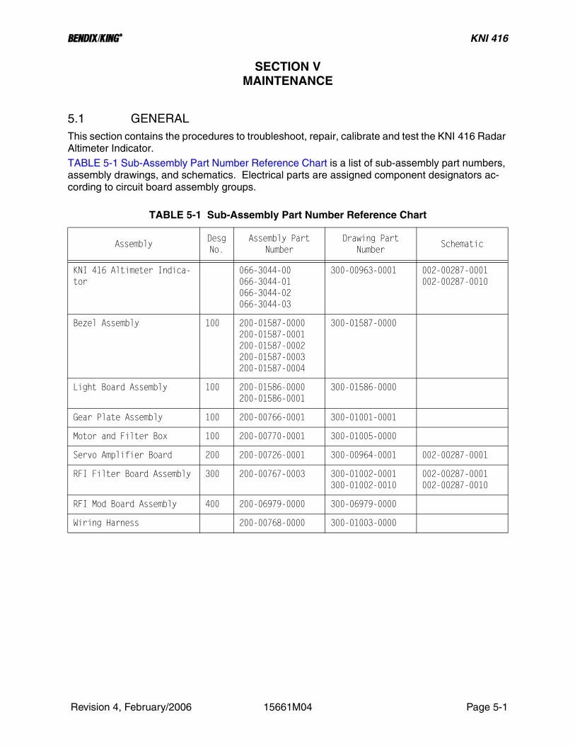
5.1 GENERALThis section contains the procedures to troubleshoot, repair, calibrate and test the KNI 416 Radar Altimeter Indicator.TABLE 5-1 Sub-Assembly Part Number Reference Chart is a list of sub-assembly part numbers, assembly drawings, and schematics. Electrical parts are assigned component designators ac-cording to circuit board assembly groups.
TABLE 5-1 Sub-Assembly Part Number Reference Chart
AssemblyDesgNo.
Assembly Part Number
Drawing Part Number
Schematic
KNI 416 Altimeter Indica-tor
066-3044-00066-3044-01066-3044-02066-3044-03
300-00963-0001 002-00287-0001002-00287-0010
Bezel Assembly 100 200-01587-0000200-01587-0001200-01587-0002200-01587-0003200-01587-0004
300-01587-0000
Light Board Assembly 100 200-01586-0000200-01586-0001
300-01586-0000
Gear Plate Assembly 100 200-00766-0001 300-01001-0001
Motor and Filter Box 100 200-00770-0001 300-01005-0000
Servo Amplifier Board 200 200-00726-0001 300-00964-0001 002-00287-0001
RFI Filter Board Assembly 300 200-00767-0003 300-01002-0001300-01002-0010
002-00287-0001002-00287-0010
RFI Mod Board Assembly 400 200-06979-0000 300-06979-0000
Wiring Harness 200-00768-0000 300-01003-0000
Revision 4, February/2006 15661M04 Page 5-1

B KNI 416
The KNI 416 Indicator is driven by the Indicator Analog Altitude output (same as the Auxiliary Out-put #1) of the KRA 405/ KRA 405B Receiver/ Transmitter. Refer to TABLE 5-2 Precision Outputs vs. Altitude and Signal Loop and KRA 405 Maintenance Manual P/N 006-05104-XXXX for detailed description of outputs.
TABLE 5-2 Precision Outputs vs. Altitude and Signal Loop
ALTITUDE(Ft)
SIGNAL LOOP IF FREQUENCY (Hz)PRECISIONEQUIPMENTOUTPUT
IND ANALOGALTITUDE &AUXILIARYOUTPUT #1
AUXILIARYOUTPUT #2
20 ft AID 40 ft AID 57 ft AID
0 520 920 1260 - 0.000 +0.400 - 0.000
10 920 1320 1660 -0.100 +0.600 - 0.000
20 1320 1720 2060 -0.200 +0.800 - 0.080
30 1720 2120 2460 -0.300 +1.000 - 0.120
40 2120 2520 2860 -0.400 +1.200 - 0.160
50 2520 2920 3260 -0.500 +1.400 - 0.200
60 2920 3320 3660 -0.600 +1.600 - 0.240
70 3320 3720 4060 -0.700 +1.800 - 0.280
80 3720 4120 4460 -0.800 +2.000 - 0.320
90 4120 4520 4860 -0.900 +2.200 - 0.360
100 4520 4920 5260 - 1.000 +2.400 - 0.400
110 4920 5320 5660 - 1.100 +2.600 - 0.440
120 5320 5720 6060 - 1.200 +2.800 - 0.480
130 5720 6120 6460 - 1.300 +3.000 - 0.520
140 6120 6520 6860 - 1.400 +3.200 - 0.560
150 6520 6920 7260 - 1.500 +3.400 - 0.600
160 6920 7320 7660 - 1.600 +3.600 - 0.640
170 7320 7720 8060 - 1.700 +3.800 - 0.680
180 7720 8120 8460 - 1.800 +4.000 - 0.720
190 8120 8520 8860 - 1.900 +4.200 - 0.760
200 8520 8920 9260 - 2.000 +4.400 - 0.800
210 8920 9320 9660 - 2.100 +4.600 - 0.840
220 9320 9720 10060 - 2.200 +4.800 - 0.880
230 9720 10120 10460 - 2.300 +5.000 - 0.920
240 10120 10520 10860 - 2.400 +5.200 - 0.960
250 10520 10920 11260 - 2.500 +5.400 - 1.000
Revision 4, February/2006 15661M04 Page 5-2

B KNI 416
260 10920 11320 11660 - 2.600 +5.600 - 1.040
270 11320 11720 12060 - 2.700 +5.800 - 1.080
280 11720 12120 12460 - 2.800 +6.000 - 1.120
290 12120 12520 12860 - 2.900 +6.200 - 1.160
300 12520 12920 13260 - 3.000 +6.400 - 1.200
310 12920 13320 13660 - 3.100 +6.600 - 1.240
320 13320 13720 14060 - 3.200 +6.800 - 1.280
330 13720 14120 14460 - 3.300 +7.000 - 1.320
340 14120 14520 14860 - 3.400 +7.200 - 1.360
350 14520 14920 15260 - 3.500 +7.400 - 1.400
360 14920 15320 15660 - 3.600 +7.600 - 1.440
370 15320 15720 16060 - 3.700 +7.800 - 1.480
380 15720 16120 16460 - 3.800 +8.000 - 1.520
390 16120 16520 16860 - 3.900 +8.200 - 1.560
400 16520 16920 17260 - 4.000 +8.400 - 1.600
410 16920 17320 17660 - 4.100 +8.600 - 1.640
420 17320 17720 18060 - 4.200 +8.800 - 1.680
430 17720 18120 18460 - 4.300 +9.000 - 1.720
440 18120 18520 18860 - 4.400 +9.200 - 1.760
450 18520 18920 19260 - 4.500 +9.400 - 1.800
460 18920 19320 19660 - 4.600 +9.600 - 1.840
470 19320 19720 20060 - 4.700 +9.800 - 1.880
480 19720 20120 20460 - 4.800 +10.000 - 1.920
490 20120 20520 20860 - 4.900 +10.200 - 1.960
500 20520 20920 21260 - 5.000 +10.400 - 2.000
600 24520 24920 25260 - 6.000 +10.700 - 2.400
700 28520 28920 29260 - 7.000 +11.000 - 2.800
800 32520 32920 33260 - 8.000 +11.300 - 3.200
900 36520 36920 37260 - 9.000 +11.600 - 3.600
TABLE 5-2 Precision Outputs vs. Altitude and Signal Loop
ALTITUDE(Ft)
SIGNAL LOOP IF FREQUENCY (Hz)PRECISIONEQUIPMENTOUTPUT
IND ANALOGALTITUDE &AUXILIARYOUTPUT #1
AUXILIARYOUTPUT #2
20 ft AID 40 ft AID 57 ft AID
Revision 4, February/2006 15661M04 Page 5-3

B KNI 416
1000 40520 40920 41260 - 10.000 +11.900 - 4.000
1100 44520 44920 45260 - 11.000 +12.200 - 4.400
1200 48520 48920 49260 - 12.000 +12.500 - 4.800
1300 52520 52920 53260 - 13.000 +12.800 - 5.200
1400 56520 56920 57260 - 14.000 +13.100 - 5.600
1500 60520 60920 61260 - 15.000 +13.400 - 6.000
1600 64520 64920 65260 - 16.000 +13.700 - 6.400
1700 68520 68920 69260 - 17.000 +14.000 - 6.800
1800 72520 72920 73260 - 18.000 +14.300 - 7.200
1900 76520 76920 77260 - 19.000 +14.600 - 7.600
2000 80520 80920 81260 - 20.000 +14.900 - 8.000
TABLE 5-2 Precision Outputs vs. Altitude and Signal Loop
ALTITUDE(Ft)
SIGNAL LOOP IF FREQUENCY (Hz)PRECISIONEQUIPMENTOUTPUT
IND ANALOGALTITUDE &AUXILIARYOUTPUT #1
AUXILIARYOUTPUT #2
20 ft AID 40 ft AID 57 ft AID
Revision 4, February/2006 15661M04 Page 5-4

B KNI 416
5.1.1 TEST EQUIPMENT
Refer to TABLE 5-3 Required Test Equipment (Using KRA 405) and FIGURE 5-3 Fabricated Test Cable (Using KRA 405) if using the KRA 405. Refer to TABLE 5-4 Required Test Equipment (Us-ing KRA 405B) and FIGURE 5-4 Fabricated Test Cable (Using KRA 405B) if using the KRA 405B.
TABLE 5-3 Required Test Equipment (Using KRA 405)
TYPE CHARACTERISTICSREPRESENTATIVE TYPE OR
EQUIVALENT
1. Radar Altimeter KRA 405
2. Power Supply 0 to 32 Vdc at 1.5A.
3. Oscilloscope 50 MHz, dual trace, delayed sweep.
Tektronix TDS1002
4. Digital AC/DC Voltmeter 5 digit. Fluke 45
5. Audio Generator 0 to 150 kHz, 0 dBm min out. Agilent 33120A
6. Audio Variable Attenuator 10 dB steps to 100 dB. HP 355D
7. Audio Variable Attenuator 1 dB steps to 10 dB. HP 355C
8. Fixed Attenuator (2 each) 4.2 to 4.4 GHz, 20 dB, VSWR 1.3 max
Narda 757C-20
9. Toggle Switch SPDT
10. Connector KRA 405 Mate 18 shell, 32 pin P/N 030-02211-0000Cannon KPT06B18-32SWBurndy BT06AC18-32SWArray PW06B18-32SWAmphenol PT06A18-32SW(SR)
11. Connector KNI 415 Mate 14 shell, 19 pin P/N 030-02210-0006Cannon KPT06B14-19SYBurndy BT06AC14-19SYArray PW06B14-19SYAmphenol PT06A14-19SY(SR)
Note: A fabricated test cable is shown in FIGURE 5-3 Fabricated Test Cable (Using KRA 405).
Revision 4, February/2006 15661M04 Page 5-5

B KNI 416
TABLE 5-4 Required Test Equipment (Using KRA 405B)
TYPE CHARACTERISTICSREPRESENTATIVE TYPE OR
EQUIVALENT
1. Radar Altimeter KRA 405B
2. Power Supply (2 each) 0 to 32 Vdc at 1.5A.
3. Oscilloscope 50 MHz, dual trace, delayed sweep.
Tektronix TDS1002
4. Digital AC/DC Voltmeter 5 digit. Fluke 45
5. Fixed Attenuator (2 each) 4.2 to 4.4 GHz, 20 dB, VSWR 1.3 max
Narda 757C-20
6. Toggle Switch (3 each) SPDT
7. Diode Silicon 1N4003 or equivalent.
8. Connector KRA 405B Mate 20 shell, 41 pin, crimpMS3126F20-41S
P/N 030-02077-0004Cannon KPSE06F20-41SArray PWR06F20-41SAmphenol PT06SE20-41S(SR)
9. Connector KNI 415 Mate 14 shell, 19 pin, crimpMS3126F14-19SY
P/N 030-02210-0012Cannon KPSE06F14-19SYAmphenol PT06SE14-19SY(SR)
Note: A fabricated test cable is shown in FIGURE 5-4 Fabricated Test Cable (Using KRA 405B).
Revision 4, February/2006 15661M04 Page 5-6

B KNI 416
5.2 TEST AND TROUBLESHOOTINGThis section provides guidelines to locate faults to the sub-assembly and component level. Use troubleshooting procedures as necessary, when a unit fails to meet the performance require-ments of the functional test procedure.Troubleshooting procedures for the KNI 416 differ slightly from align procedures. After trouble-shooting procedures have been completed, the unit should be calibrated and aligned by proce-dures outlined in paragraph 5.3 CALIBRATION AND ALIGNMENT.Alignment procedures are to be used after misalignment has been isolated by the use of the trou-bleshooting flow charts, and/or other troubleshooting techniques, and to adjust levels to customer specifications.
CAUTION:THIS EQUIPMENT CONTAINS ELECTRO-STATIC DISCHARGE SENSITIVE (ESDS)COMPONENTS. EQUIPMENT ASSEMBLIESAND ESDS COMPONENTS MUST BE HAN-DLED IN ACCORDANCE WITH SPECIALESDS HANDLING PROCEDURES.
Contained within this section are troubleshooting flow charts, troubleshooting sequence charts, and detailed troubleshooting procedures.Prior to any tests, the units should be checked visually for foreign objects, broken wires, loose screws, broken or blistered components.It is assumed the unit passed previous performance tests prior to the current failure.For troubleshooting purposes remove the dust cover and connect the equipment as directed in the appropriate test set-up using the KRA 405 or KRA 405B. It is not necessary to disassemble the radio unless noted otherwise.The sequence of troubleshooting follows the troubleshooting flow chart of FIGURE 5-5 Trouble-shooting Flow Chart.The flow chart and troubleshooting procedures assume that signals under test are checked on the signal terminating board, or continuity is checked from the signal source board to the signal termi-nating board.When a circuit board is suspected of a failure, all power supply voltages and signal inputs, as well as continuity of signal output paths to terminating boards, must be checked before replacing the board.The correct troubleshooting procedure is determined by the type of failure in the functional test procedure. Technicians should use traditional troubleshooting methods to isolate to the assembly and component level. Schematic diagrams and theory of operation are provided to assist trouble-shooting to the component level. After repair and reinsertion of any assembly, the KNI 416 should be checked again for any other faults. When all the assemblies have been repaired and reinserted, the functional test should be performed to assure that the KNI 416 is again operating satisfactorily.
5.2.1 KNI 416 TEST SET-UP AND TESTING (USING KRA 405)
A simulated Analog Altitude voltage is required to test the KNI 416 indicators. This signal is pro-duced by driving the KRA 405 R/T Precision Outputs to the correct voltage with the test IF signal. The test signal should be applied through the two audio attenuators to TP201 of the KRA 405 R/T as required.
Revision 4, February/2006 15661M04 Page 5-7

B KNI 416
Unless noted otherwise, set the audio attenuators to 0 dB.Test set-up is shown in FIGURE 5-1 Test Set-Up (Using KRA 405). All tests using the KRA 405 R/T are performed with the 40 foot AID selected (Pins a and j of P4051 jumpered).Initially the 27.5 Vdc input to the KRA 405 and KNI 416 should be adjusted to 22.5 ± 0.5 Vdc.The RFI Filter assembly may be removed according to procedures in paragraph 5.6.1.1 RFI Filter Assembly to further expose the Servo Amplifier Board Assembly.The sequence of test and troubleshooting follows the troubleshooting flow chart FIGURE 5-5 Troubleshooting Flow Chart.
1. Servoed Pointer Accuracy and Response Time2. Servo Error Detector and Flag Operation 3. DH Operation4. DH Pushbutton Lamp Logic 5. DH Lamp and Dimmer 6. Panel Lamps
Revision 4, February/2006 15661M04 Page 5-8

B KNI 416
FIGURE 5-1 Test Set-Up (Using KRA 405)
Revision 4, February/2006 15661M04 Page 5-9

B KNI 416
5.2.1.1 SERVOED POINTER ACCURACY AND RESPONSE TIME (w/ KRA 405)
1. Using the test IF input to the KRA 405 R/T, adjust the indicator pointer to 0 feet, 150 feet, 400 feet, and 2000 feet.
The indicator Analog Altitude should be +0.40 ± 0.06 Vdc, +3.40 ± 0.09 Vdc, +8.40 ± 0.24 Vdc, and +14.9 ± 0.24 Vdc respectively.
2. Check the servo response time.
3. Adjust the test signal frequency until the pointer is at 0 feet.
4. Remove the test IF input and the pointer should revolve clockwise to behind the mask within 1.5 seconds.
5. Reconnect the test IF input. The pointer should return 0 feet with less than 3 over-shoots in less than 2 seconds.
Troubleshooting procedures for the servo mechanism and amplifier.
1. If the pointer was merely inaccurate, calibrate the servo according to the procedures in paragraph 5.3 CALIBRATION AND ALIGNMENT and proceed to the next para-graph.
2. Set the Indicator Analog Altitude to +2.40 ± 0.01 Vdc.
3. Connect the DVM between TP218 and TP217. The voltage should be 3.48 ± 0.10 Vdc. If not, check I301A, I301B, Q301, and I204A.
4. Set the Indicator Analog Altitude to +10.4 ± 0.015 Vdc.
5. Connect the DVM between TP218 and TP217. The voltage should be 7.98 ± 0.03 Vdc. If not, check Q209, CR214, and alignment procedures.
6. Check for +11.7 ± 0.7 Vdc between TP202 and TP217. Check CR202.
7. Check the motor reference voltage at TP211. If should be 11 ± 1 Vdc with the motor stationary.
8. Check the voltage at TP210. The difference between TP210 and TP211 should be less than 5 volts. Check I201B, Q203, Q204, Q102, Q103, and B101.
5.2.1.2 SERVO ERROR DETECTOR AND FLAG OPERATION (w/ KRA 405)
1. Switch the pointer revolve switch in the test cable to "revolve." The flag should come into view within 0.5 ± 0.2 seconds.
a. If the flag does not come into view, verify the servo error detector is working properly by monitoring TP213. TP213 should be +27.5 ± 3.0 Vdc when the pointer is revolving and Q207 should be off.
b. Check Q207, I205A, and I205B. TP214 should be 0 volts and Q101 should be off allowing the flag to come into view.
c. Switch the pointer revolve switch to "normal" and verify the flag goes out of view. TP213 should be 23 ± 2 Vdc. Transistors Q207 and Q101 should be on.
Revision 4, February/2006 15661M04 Page 5-10

B KNI 416
d. Push self test. The flag should come into view. The pointer should indicate 50 ± 5 feet. Check CR213 and S101.
5.2.1.3 DH OPERATION (w/ KRA 405)
1. Increase the primary power supply voltage to +27.5 ± 0.5 Vdc.
2. Adjust the DH bug to bracket each altitude listed below.
3. Decrease the Analog Altitude toward the same altitude.
4. Observe the Analog Altitude at which the DH lamp lights. The voltage should be within the limits specified for each altitude.
5. Check the DH hysteresis by setting the DH bug to 150 feet.
6. Decrease the Analog Altitude until the lamp just lights. Record the voltage.
7. Increase the Analog Altitude until the DH lamp goes out. Record the voltage.
The difference between the two voltages should be 200 to 350 millivolts.
Troubleshooting procedures for the DH. If the DH is only inaccurate, proceed to the next para-graph.
1. Check the DH comparator for correct operation. Monitor TP204 and repeat the above steps for DH operation.
TP204 should be +27 ± 3 Vdc when the Analog Altitude is less than the DH and -2.5 ± 2.5 Vdc when the Analog Altitude is greater than the DH.
2. If the comparator is functioning properly, proceed to the next paragraph to check the DH lamp logic. If not, check I201A.
5.2.1.4 DH PUSHBUTTON LAMP LOGIC (w/ KRA 405)
1. Set the DH bug to 150 feet.
2. Decrease the Analog Altitude until the lamp lights.
3 Depress the DH lamp; the lamp should go out.
4. Press the self test button; the lamp should light.
5. Depress the DH light to extinguish the light.
DH Altitude Analog Altitude
1000 feet +11.90 ± 0.150 Vdc
400 feet + 8.40 + 0.400 Vdc
150 feet + 3.40 + 0.150 Vdc
50 feet + 1.40 + 0.100 Vdc
Revision 4, February/2006 15661M04 Page 5-11

B KNI 416
6. Increase the Analog Altitude to 250 feet then slowly decrease it again. The lamp should light when DH is reached.
7. Depress the DH light to extinguish the lamp.
8. Cycle the primary power supply OFF/ON. The lamp should light when the power is turned on.
Troubleshooting procedures for the lamp logic.
1. Adjust the Analog Altitude until TP204 switches to +27 Vdc.
2. Verify a 90 ± 20 msec pulse at TP205 as the DH lamp is depressed. Check I202C, I202D, and DS101B.
3. Verify pin 3 of I202A is 0 ± 0.5 Vdc. Check I201A.
4. Verify pin 4 of I203A is 0 ± 0.5 Vdc. Check that Q208 is off.
5. Pin 4 of I203A should be +13 Vdc when the push-to-test button is depressed. Check Q208 and S101.
6. Repeatedly depress the DH lamp. The Q and t outputs of I203A (pins 1 and 2) should change logic levels each time the DH lamp is depressed. Check I203A.
7. Pin 4 of I202B should change logic states each time the DH lamp is depressed. Check I202B.
8. TP206 should alternate between the primary power supply voltage and +0.5 ± 0.5 Vdc each time the DH lamp is depressed. Check operation of Q201 an K201.
9. Verify that pin 1 of K201 is 0 volts when TP206 is at +0.5 Vdc. When TP206 is +27 Vdc, pin 1 of K201 should be floating if the light bulb is burned out or the wiring har-ness is broken. Otherwise, pin 1 should be greater than +11 Vdc. Check K201.
10. Proceed to next paragraph if all tests are OK.
5.2.1.5 DH LAMP AND DIMMER (w/ KRA 405)
1. With the DH lamp on, place an opaque object over the photocell (V101) located on the bezel. The DH lamp should dim.
Troubleshooting procedures for the dimmer and lamp.
1. Verify that pin 1 of K201 and E110 is at 0 volts.
2. With the photocell protected from light, the emitter of Q104 and E109 should be +11.5 ± 2 Vdc. With the photocell exposed to light, the emitter of Q104 and E109 should be 25 ± 2 Vdc.
3. Check Q104, V101, and the wiring harness to V101 and DS101.
4. If the voltages of E109 and E110 are correct and the lamp does not work, replace DS101A (P/N 037-00009-0003). The lamp can be exposed by pulling straight out on the lens.
Revision 4, February/2006 15661M04 Page 5-12

B KNI 416
5.2.1.6 PANEL LAMPS (w/ KRA 405)
1. Apply appropriate panel lamp power to the unit. Check that all five (5) lamps are on.
066-3044-01/03 27 Vdc - Pin F of P4161
066-3044-00/02 5 Vdc - Pin U of P4161
Replace 28 V bulbs with P/N 037-00013-0001.
Replace 5 V bulbs with P/N 037-00012-0001.
5.2.2 KNI 416 TEST SET-UP AND TESTING (USING KRA 405B)
In addition to the required dc voltages supplied by the KRA 405B, a simulated Analog Altitude volt-age is required to test the KNI 416 indicators. This signal is produced by driving the KRA 405B R/T Precision Outputs to the correct voltage using the P405B1-m; Alt_Test_Input. The Alt_Test_Enable_1 and Alt_Test_Enable_2 lines must be grounded to enable the P405B1-m; Alt_Test_Input. The scale factor for P405B1-m; Alt_Test_Input is +10 mV / foot. A 0 to 25Vdc input = a 0 to 2500 foot analog output.
NOTE:The KRA 405B with software version -0101 requiresan RF signal with loop attenuation 6 dB greater thanlockup to provide a threshold signal for the uproces-sor at any altitude between 0 and 2500 feet. Soft-ware versions greater than -0101 do not have thisconstraint.
NOTE:When using the Alt_Test_Input the length of the an-tenna cables must be taken into consideration. Theelectrical length of the total antenna coax in feetmust be added to the variable power supply voltage.For example: If the RT was zeroed and the calibra-tion included 30 electrical feet of coax and round-tripRF path to ground, and simulation of 50 feet altitudeis desired, the variable power supply is set to 0.5V +0.3V for a total of 0.8Vdc which equals the desired50 feet + the 30 feet of antenna coax and round-tripRF path to ground.
If the RF path length used for calibration is not known, then adjust the power supply until the Analog_Altitude Hi voltage is 0.400Vdc. This power supply voltage becomes the offset voltage required at each altitude to compensate for the RF path length.Test hook-up is shown in FIGURE 5-2 Test Set-Up (Using KRA 405B).Initially the 27.5Vdc input to the KRA 405B and KNI 416 should be adjusted to 22.5 ±0.5VdcThe RFI Filter assembly may be removed according to procedures in paragraph 5.6.1.1 RFI Filter Assembly to further expose the Servo Amplifier Board Assembly.
Revision 4, February/2006 15661M04 Page 5-13

B KNI 416
The sequence of test and troubleshooting follows the troubleshooting flow chart in FIGURE 5-5 Troubleshooting Flow Chart.
1. Servoed Pointer Accuracy and Response Time2. Servo Error Detector and Flag Operation3. DH Operation4. DH Pushbutton Lamp Logic5. DH Lamps and Dimmer6. Panel Lamps
FIGURE 5-2 Test Set-Up (Using KRA 405B)
Revision 4, February/2006 15661M04 Page 5-14

B KNI 416
5.2.2.1 SERVOED POINTER ACCURACY AND RESPONSE TIME (w/ KRA 405B)
1. Use the variable power supply into P4051B-m; Alt_Test_Input, to adjust the indica-tor pointer to 0 feet, 150 feet, 400 feet, and 2000 feet.
The Indicator Analog Altitude should be +0.400 ± 0.06Vdc, +3.40 ± 0.09Vdc, +8.40 ± 0.24Vdc, and +14.9 ± 0.24Vdc.
2. Check the Servo response time.
3. Adjust the Altitude_Test_Input voltage until the pointer is at 0 feet.
4. Set the Altitude_Test_Enable_1 switch to off, and the pointer should revolve clock-wise to behind the mask within 1.5 seconds.
5. Set the Altitude _ Test_Enable_1 switch to on, and the pointer should return to 0 feet with less than 3 overshoots within 2 seconds.
Troubleshooting procedures for the servo mechanism and amplifier.
1. If the pointer was merely inaccurate, calibrate the servo according to the procedures in paragraph 5.3 CALIBRATION AND ALIGNMENT and proceed to the next para-graph.
2. Set the Indicator Analog Altitude to +2.40 ± 0.01 Vdc.
3. Connect the DVM between TP218 and TP217. The voltage should be 3.48 ± 0.10 Vdc. If not, check I301A, I301B, Q301, and I204A.
4 Set the Indicator Analog Altitude to +10.4 ± 0.015 Vdc.
5. Connect the DVM between TP218 and TP217. The voltage should be 7.98 ± 0.03 Vdc. If not, check Q209, CR214, and alignment procedures.
6. Check for +11.7 ± 0.7 Vdc between TP202 and TP217. Check CR202.
7. Check the motor reference voltage at TP211. If should be 11 ± 1 Vdc with the motor stationary.
8. Check the voltage at TP210. The difference between TP210 and TP211 should be less than 5 volts.
9. Check I201B, Q203, Q204, Q102, Q103, and B101.
5.2.2.2 SERVO ERROR DETECTOR AND FLAG OPERATION (w/ KRA 405B)
1. Switch the pointer revolve switch in the test cable to "revolve." The flag should come into view within 0.5 ± 0.2 seconds.
a. If the flag does not come into view, verify the servo error detector is working properly by monitoring TP213. TP213 should be +27.5 ± 3.0 Vdc when the pointer is revolving and Q207 should be off.
b. Check Q207, I205A, and I205B. TP214 should be 0 volts andQ101 should be off allowing the flag to come into view.
Revision 4, February/2006 15661M04 Page 5-15

B KNI 416
c. Switch the pointer revolve switch to "normal" and verify the flag goes out of view. TP213 should be 23 ± 2 Vdc. Q207 and Q101 should be on.
d. Push self test. The flag should come into view. The pointer should indicate 50 ± 5 feet. Check CR213 and S101.
5.2.2.3 DH OPERATION (w/ KRA 405B)
1. Increase the primary power supply voltage to +27.5 ± 0.5 Vdc.
2. Adjust the DH bug to bracket each altitude listed below.
3. Decrease the Analog Altitude toward the same altitude.
4. Observe the Analog Altitude at which the DH lamp lights. The voltage should be within the limits specified for each altitude.
5. Check the DH hysteresis by setting the DH bug to 150 feet.
6. Decrease the Analog Altitude until the lamp just lights.
7. Record the voltage.
8. Increase the Analog Altitude until the DH lamp goes out.
9. Record the voltage.
The difference between the two voltages should be 200 to 350 millivolts.
Troubleshooting procedures for the DH. If the DH is only inaccurate, proceed to the next para-graph.
1. Check the DH comparator for correct operation.
2. Monitor TP204 and repeat the above steps for DH operation. TP204 should be +27 ± 3 Vdc when the Analog Altitude is less than the DH and -2.5 ± 2.5 Vdc when the Analog Altitude is greater than the DH.
3. If the comparator is functioning properly, proceed to the next paragraph to check the DH lamp logic. If not, check I201A.
DH Altitude Analog Altitude
1000 feet +11.90 ± 0.150 Vdc
400 feet + 8.40 + 0.400 Vdc
150 feet + 3.40 + 0.150 Vdc
50 feet + 1.40 + 0.100 Vdc
Revision 4, February/2006 15661M04 Page 5-16

B KNI 416
5.2.2.4 DH PUSHBUTTON LAMP LOGIC (w/ KRA 405B)
1. Set the DH bug to 150 feet.
2. Decrease the Analog Altitude until the lamp lights.
3. Depress the DH lamp; the lamp should go out.
4. Press the self test button; the lamp should light.
5. Depress the DH light to extinguish the light.
6. Increase the Analog Altitude to 250 feet then slowly decrease it again. The lamp should light when DH is reached.
7. Depress the DH light to extinguish the lamp.
8. Cycle the primary power supply OFF/ON. The lamp should light when the power is turned on.
Troubleshooting procedures for the lamp logic.
1. Adjust the Analog Altitude until TP204 switches to +27 Vdc.
2. Verify a 90 ± 20 msec pulse at TP205 as the DH lamp is depressed. Check I202C, I202D, and DS101B.
3. Verify pin 3 of I202A is 0 ± 0.5 Vdc. Check I201A.
4. Verify pin 4 of I203A is 0 ± 0.5 Vdc. Check that Q208 is off.
5. Pin 4 of I203A should be +13 Vdc when the push-to-test button is depressed.
6. Check Q208 and S101.
7. Repeatedly depress the DH lamp. The Q and t outputs of I203A (pins 1 and 2) should change logic levels each time the DH lamp is depressed. Check I203A.
8. Pin 4 of I202B should change logic states each time the DH lamp is depressed.
9. Check I202B.
10. TP206 should alternate between the primary power supply voltage and +0.5 ± 0.5 Vdc each time the DH lamp is depressed.
11. Check operation of Q201 an K201.
12. Verify that pin 1 of K201 is 0 volts when TP206 is at +0.5 Vdc. When TP206 is +27 Vdc, pin 1 of K201 should be floating if the light bulb is burned out or the wiring har-ness is broken. Otherwise, pin 1 should be greater than +11 Vdc. Check K201.
13. Proceed to the next paragraph DH Lamp and Dimmer if all tests are OK.
Revision 4, February/2006 15661M04 Page 5-17

B KNI 416
5.2.2.5 DH LAMP AND DIMMER (w/ KRA 405B)
With the DH lamp on, place an opaque object over the photocell (V101) located on the bezel. The DH lamp should dim.Troubleshooting procedures for the dimmer and lamp.
1. Verify that pin 1 of K201 and E110 is at 0 volts.
2. With the photocell protected from light, the emitter of Q104 and E109 should be +11.5 ± 2 Vdc. With the photocell exposed to light, the emitter of Q104 and E109 should be 25 ± 2 Vdc. Check Q104, V101, and the wiring harness to V101 and DS101.
3. If the voltages of E109 and E110 are correct and the lamp does not work, replace DS101A (P/N 037-00009-0003). The lamp can be exposed by pulling straight out on the lens.
5.2.2.6 PANEL LAMPS (w/ KRA 405B)
Apply appropriate panel lamp power to the unit. Check that all five (5) lamps are on.
Replace 28 V bulbs with P/N 037-00013-0001.Replace 5 V bulbs with P/N 037-00012-0001.
066-3044-01/03 27 Vdc - Pin F of P4161
066-3044-00/02 5 Vdc - Pin U of P4161
Revision 4, February/2006 15661M04 Page 5-18

B KNI 416
5.3 CALIBRATION AND ALIGNMENTThis section contains the information necessary to calibrate the KNI 416 Indicator. The next sec-tion is a functional performance test.
5.3.1 CALIBRATION AND ALIGNMENT (USING KRA 405)
Calibration and alignment must proceed in the order listed below to minimize interference between various adjustments. An operational KRA 405 must available before starting this section.
1. Servo Pot Zero2. Servo Calibration 3. DH Pot Zero4. DH Pot Calibration5. KNI 416 Performance Test
A simulated Analog Altitude Voltage is required to test the KNI 416 Indicator. This signal is pro-duced by driving the KRA 405 R/T Precision Outputs to the correct voltage with a test IF signal.The test IF signal is produced by terminating the audio generator in a 51 ohm resistor and setting the output level to 226 mV for each frequency setting.The test signal should be applied through the two audio attenuators to TP201 of the KRA 405 R/T as required.Unless noted otherwise, set the audio attenuators to 0 dB.See TABLE 5-2 Precision Outputs vs. Altitude and Signal Loop for a list of Precision Outputs vs. Altitude vs. IF frequency.Test set-up is shown in FIGURE 5-1 Test Set-Up (Using KRA 405).All tests are performed with the 40 foot AID selected on the KRA 405 R/T (pins a and J of P4051 jumpered).Initially the 27.5 Vdc input to the KRA 405 and KNI 416 should be adjusted to 22.5 ± 0.5 Vdc.It is recommended that all measurements on switching waveforms, comparator outputs and sim-ilar voltages be monitored with an oscilloscope so that the oscillations and abnormal waveforms may be detected.Precision voltage measurements should be made with an accurate digital voltmeter.
5.3.1.1 SERVO POT ZERO (w/ KRA 405)
1. Using the test IF signal, adjust the Analog Altitude voltage to +0.900 ± 0.005 Vdc.
2. Loosen the screws holding the clamps on the servo pot R102. Rotate R102 until the pointer is centered on the 25 foot graduation.
3. Tighten the screws.
5.3.1.2 SERVO CALIBRATION (w/ KRA 405)
1. Adjust the analog altitude voltage to +3.40 ±0.01 Vdc.
2. Adjust the servo calibration potentiometer R219 until the pointer is centered on the 150 foot graduation.
3. Adjust the analog altitude voltage until the pointer is centered on the 25 foot gradu-ation.
Revision 4, February/2006 15661M04 Page 5-19

B KNI 416
The analog altitude voltage should lie between +0.875 and +0.925 Vdc. If the analog altitude is not within the above limits, repeat sections 5.4.1.2 SERVO ACCURACY (w/ KRA 405) and 5.4.1.3 SERVO RESPONSE (w/ KRA 405).
4. Adjust the analog altitude voltage to +8.40 ±0.01 Vdc.
5. Adjust the breakpoint potentiometer, R257, until the pointer is centered on the 400 foot graduation.
For units marked with Mod 7 (S/N 3811 and higher):
1. Adjust the analog altitude voltage to +14.9 ±0.24 Vdc.
2. Adjust R264 to center the pointer on the 2000 foot graduation.
5.3.1.3 DH POT ZERO (w/ KRA 405)
1. Set the Analog Altitude to +1.40 ± 0.01 Vdc.
2. Adjust the DH knob until the DH bug brackets 50 feet.
3. Loosen the screws holding the clamps on the DH potentiometer (R101).
4. Rotate R101 until the DH lamp lights. The voltage at TP203 should be +1.40 ± 0.05 Vdc for units marked Mod 5 (S/N 3810 and lower) and +2.028 ± 0.028 Vdc for Mod 7 (S/N 3811 and higher).
5. Tighten the screws.
5.3.1.4 DH POT CALIBRATION (w/ KRA 405)
1. Set the Analog Altitude to +11.90 ± 0.01 Vdc.
2. Adjust the DH knob until the DH bug brackets 1000 feet.
3. Adjust the DH calibration potentiometer (R203 Mod 5 and lower, R261 for Mod 7) until the light goes out. Slowly adjust the potentiometer until the DH lamp lights.
4. Set the DH bug to 50 feet. The voltage at TP203 should be +11.90 ± 0.1 Vdc.
5. Decrease the Analog Altitude voltage until the DH lamp lights. The Analog Altitude should be between +1.34 and +1.46 Vdc.
6. If the Analog Altitude is not within the limits, repeat DH Pot Zero and DH Pot Cali-bration paragraphs.
Revision 4, February/2006 15661M04 Page 5-20

B KNI 416
5.3.2 CALIBRATION AND ALIGNMENT (USING KRA 405B)
Calibration and alignment must proceed in the order listed below to minimize interference between various adjustments. An operational KRA 405B must available before starting this section.
1. Servo Pot Zero2. Servo Calibration 3. DH Pot Zero4. DH Pot Calibration5. KNI 416 Performance Test
A simulated Analog Altitude Voltage is required to test the KNI 416 indicator. This signal is pro-duced by driving the KRA 405B Altitude_Test_Input with a dc voltage while Altitude_Test_Enable_1 and Altitude_Test_Enable_2 lines are grounded. This dc voltage will vary from 0 to 25Vdc which represents 0 to 2500 feet altitude.
NOTE:KRA 405B software version -0101 requires an RFsignal with loop attenuation 6 dB greater than lockupto provide a threshold signal for the uprocessor atany altitude between 0 and 2500 feet. Software ver-sions greater than -0101 do not have this constraint.
NOTE:When using the Alt_Test_Input the length of the an-tenna cables must be taken into consideration. Theelectrical length of the total antenna coax in feetmust be added to the variable power supply voltage.For example: If the RT was zeroed and the calibra-tion included 30 electrical feet of coax and round-tripRF path to ground, and simulation of 50 feet altitudeis desired, the variable power supply is set to 0.5V +0.3V for a total of 0.8Vdc which equals the desired50 feet + the 30 feet of antenna coax and round-tripRF path to ground.
If the RF path length used for calibration is not known, then adjust the power supply until the Analog_Altitude Hi voltage is 0.400Vdc. This power supply voltage becomes the offset voltage required at each altitude to compensate for the RF path length.See TABLE 5-2 Precision Outputs vs. Altitude and Signal Loop for a list of Precision Outputs vs. Altitude vs. IF frequency.Test set-up is shown in FIGURE 5-2 Test Set-Up (Using KRA 405B).Initially the 27.5 Vdc input to the KRA 405B and KNI 416 should be adjusted to 22.5 ± 0.5 Vdc.It is recommended that all measurements on switching waveforms, comparator outputs and sim-ilar voltages be monitored with an oscilloscope so that the oscillations and abnormal waveforms may be detected.Precision voltage measurements should be made with an accurate digital voltmeter.
Revision 4, February/2006 15661M04 Page 5-21

B KNI 416
5.3.2.1 SERVO POT ZERO (w/ KRA 405B)
1. Using the Altitude_Test_Input, adjust the Analog Altitude voltage to +0.900 ± 0.005 Vdc.
2. Loosen the screws holding the clamps on the servo pot R102.
3. Rotate R102 until the pointer is centered on the 25 foot graduation.
4. Tighten the screws.
5.3.2.2 SERVO CALIBRATION (w/ KRA 405B)
1. Adjust the analog altitude voltage to +3.40 ±0.01 Vdc.
2. Adjust the servo calibration potentiometer R219 until the pointer is centered on the 150 foot graduation.
3. Adjust the analog altitude voltage until the pointer is centered on the 25 foot gradu-ation.
The analog altitude voltage should lie between +0.875 and +0.925 Vdc. If the analog altitude is not within the above limits, repeat sections 5.4.2.2 SERVO ACCURACY (w/ KRA 405B) and 5.4.2.3 SERVO RESPONSE (w/ KRA 405B).
4. Adjust the analog altitude voltage to +8.40 ±0.01 Vdc.
5. Adjust the breakpoint potentiometer, R257, until the pointer is centered on the 400 foot graduation.
For units marked with Mod 7 (S/N 3811 and higher):
1. Adjust the analog altitude voltage to +14.9 ±0.24 Vdc.
2. Adjust R264 to center the pointer on the 2000 foot graduation.
5.3.2.3 DH POT ZERO (w/ KRA 405B)
1. Set the Analog Altitude to +1.40 ± 0.01 Vdc.
2. Adjust the DH knob until the DH bug brackets 50 feet.
3. Loosen the screws holding the clamps on the DH potentiometer (R101).
4. Rotate R101 until the DH lamp lights. The voltage at TP203 should be +1.40 ± 0.05 Vdc for units marked Mod 5 (S/N 3810 and lower) and +2.028 ± 0.028 Vdc for Mod 7 (S/N 3811 and higher).
5. Tighten the screws.
5.3.2.4 DH POT CALIBRATION (w/ KRA 405B)
1. Set the Analog Altitude to +11.90 ± 0.01 Vdc.
2. Adjust the DH knob until the DH bug brackets 1000 feet.
Revision 4, February/2006 15661M04 Page 5-22

B KNI 416
3. Adjust the DH calibration potentiometer (R203 Mod 5 and lower, R261 for Mod 7) until the light goes out.
4. Slowly adjust the potentiometer until the DH lamp lights.
5. Set the DH bug to 50 feet. The voltage at TP203 should be +11.90 ± 0.1 Vdc.
6. Decrease the Analog Altitude voltage until the DH lamp lights. The Analog Altitude should be between +1.34 and +1.46 Vdc.
7. If the Analog Altitude is not within the limits, repeat DH Pot Zero and DH Pot Cali-bration paragraphs.
5.4 KNI 416 PERFORMANCE TEST
5.4.1 KNI 416 PERFORMANCE TEST (USING KRA 405)
Place the dust cover on the KNI 416. Test hook-up is shown in FIGURE 5-1 Test Set-Up (Using KRA 405). Turn on KRA 405 and KNI 416 Indicator. The pointer and flag should be hidden from view.
5.4.1.1 FLAG OPERATION (w/ KRA 405)
1. Press the self test button. The flag should come into view immediately and the point-er should indicate 50 ± 5 feet.
2. Switch the pointer revolve switch to "revolve" and within 0.6 seconds the flag should come into view.
3. Return the switch to normal and the pointer should return to its original position and the flag should be hidden from view.
NOTE:When the needle is revolving continuously it shouldnot hit the flag or the face plate at any point.
5.4.1.2 SERVO ACCURACY (w/ KRA 405)
1. Increase the Analog Altitude from 0.0 Vdc until the pointer is centered on each grad-uation listed below. The Analog Altitude should be within the limits specified for each altitude.
2. Repeat the above step, decreasing the Analog Altitude from +15 Vdc.
GRADUATION ANALOG ALTITUDE
0 feet + 0.40 ± 0.06 Vdc
150 feet + 3.40 ± 0.09 Vdc
400 feet + 8.40 ± 0.24 Vdc
2000 feet +14.90 ± 0.24 Vdc
Revision 4, February/2006 15661M04 Page 5-23

B KNI 416
5.4.1.3 SERVO RESPONSE (w/ KRA 405)
1. Set the Analog Altitude to +0.40 ± 0.01 Vdc.
2. Remove the test IF signal from TP201 and observe the pointer. The pointer should revolve clockwise and reach its new position within 1.5 seconds with no more than three (3) overshoots.
3. Reconnect the test IF signal to TP201 and observe the pointer. The pointer should revolve counterclockwise and reach its new position within 2 seconds with no more than three (3) overshoots.
5.4.1.4 DH ACCURACY (w/ KRA 405)
1. Increase the primary power supply voltage to +27.5 ± 0.5 Vdc.
2. Adjust the DH bug to bracket each altitude listed below.
3. Decrease the Analog Altitude toward the same altitude.
4. Observe the Analog Altitude at which the DH lamp lights. The voltage should be within the limits specified in the following table for each altitude listed.
5. Check DH hysteresis as follows:
A. Set the DH bug to 150 feet.
B. Decrease the Analog Altitude until the DH lamp just lights'.
C. Record the resultant voltage.
D. Increase the Analog Altitude until the DH lamp goes out.
E. Record this voltage also.
The difference between the two recorded voltages should be between 200 and 350 mVdc.
5.4.1.5 DH LAMP LOGIC AND DIMMER (w/ KRA 405)
1. Set the DH bug to 150 feet.
2. Decrease the Analog Altitude until the lamp just lights. The DH lamp should go out when it is pressed.
3. Press the self-test button; the DH lamp should light.
DH ALTITUDE ANALOG ALTITUDE
1000 feet +11.90 ± 0.20 Vdc
400 feet + 8.40 ± 0.24 Vdc
150 feet + 3.40 ± 0.09 Vdc
50 feet + 1.40 ± 0.06 Vdc
Revision 4, February/2006 15661M04 Page 5-24

B KNI 416
4. Press the DH lamp to extinguish the light.
5. Increase the Analog Altitude to 300 feet.
6. Slowly decrease it again. When the pointer reaches 150 ± 5 feet, the DH lamp should light.
7. Press the DH lamp to extinguish the light.
8. Turn off the primary power. When the primary power is restored, the DH lamp should light.
9. Place an opaque object in front of the photocell VT101. The DH lamp should dim.
5.4.1.6 PANEL LIGHTS (w/ KRA 405)
1. Apply appropriate panel lamp power to the unit.
2. Check that all five (5) panel lamps are burning.
5.4.2 KNI 416 PERFORMANCE TEST (USING KRA 405B)
1. Place the dust cover on the KNI 416.2. Test hook-up is shown in FIGURE 5-2 Test Set-Up (Using KRA 405B).3. Turn on KRA 405B and KNI 416 Indicator.4. Set the Altitude_Test_Enable_1 and 2 switches high (off). The pointer and flag
should be hidden from view behind the mask.
5.4.2.1 FLAG OPERATION (w/ KRA 405B)
1. Press the self test button. The flag should come into view immediately and the point-er should indicate 50 ± 5 feet.
2. Switch the pointer revolve switch to "revolve" and within 0.6 seconds the flag should come into view.
3. Return the switch to normal and the pointer should return to its original position and the flag should be hidden from view.
NOTE:When the needle is revolving continuously it shouldnot hit the flag or the face plate at any point.
5.4.2.2 SERVO ACCURACY (w/ KRA 405B)
1. Increase the Analog Altitude from 0.0 Vdc until the pointer is centered on each grad-uation listed below. The Analog Altitude should be within the limits specified for each altitude.
2. Repeat the above step, decreasing the Analog Altitude from +15 Vdc.
066-3044-01/03 27 Vdc - Pin F of P4161
066-3044-00/02 5 Vdc - Pin U of P4161
Revision 4, February/2006 15661M04 Page 5-25

B KNI 416
5.4.2.3 SERVO RESPONSE (w/ KRA 405B)
1. Set the Analog Altitude to +0.40 ± 0.01 Vdc.
2. Remove the dc input from Altitude_ Test_ Input and observe the pointer. The point-er should revolve clockwise and hide itself from view behind the mask within 1.5 sec-onds with no more than three (3) overshoots.
3. Reconnect the dc input from Altitude_ Test_ Input and observe the pointer. The pointer should revolve counterclockwise and reach its new position within 2 seconds with no more than three (3) overshoots.
5.4.2.4 DH ACCURACY (w/ KRA 405B)
1. Increase the primary power supply voltage to +27.5 ± 0.5 Vdc.
2. Adjust the DH bug to bracket each altitude listed below.
3. Decrease the Analog Altitude toward the same altitude.
4. Observe the Analog Altitude at which the DH lamp lights. The voltage should be within the limits specified in the following table for each altitude listed.
5. Check DH hysteresis as follows:
A. Set the DH bug to 150 feet.
B. Decrease the Analog Altitude until the DH lamp just lights.
C. Record the resultant voltage.
D. Increase the Analog Altitude until the DH lamp goes out.
E. Record this voltage also.
GRADUATION ANALOG ALTITUDE
0 feet + 0.40 ± 0.06 Vdc
150 feet + 3.40 ± 0.09 Vdc
400 feet + 8.40 ± 0.24 Vdc
2000 feet +14.90 ± 0.24 Vdc
DH ALTITUDE ANALOG ALTITUDE
1000 feet +11.90 ± 0.20 Vdc
400 feet + 8.40 ± 0.24 Vdc
150 feet + 3.40 ± 0.09 Vdc
50 feet + 1.40 ± 0.06 Vdc
Revision 4, February/2006 15661M04 Page 5-26
B KNI 416
The difference between the two recorded voltages should be between 200 and 350 mVdc.
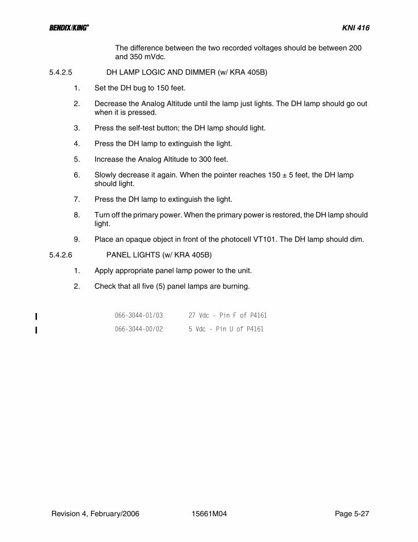
5.4.2.5 DH LAMP LOGIC AND DIMMER (w/ KRA 405B)
1. Set the DH bug to 150 feet.
2. Decrease the Analog Altitude until the lamp just lights. The DH lamp should go out when it is pressed.
3. Press the self-test button; the DH lamp should light.
4. Press the DH lamp to extinguish the light.
5. Increase the Analog Altitude to 300 feet.
6. Slowly decrease it again. When the pointer reaches 150 ± 5 feet, the DH lamp should light.
7. Press the DH lamp to extinguish the light.
8. Turn off the primary power. When the primary power is restored, the DH lamp should light.
9. Place an opaque object in front of the photocell VT101. The DH lamp should dim.
5.4.2.6 PANEL LIGHTS (w/ KRA 405B)
1. Apply appropriate panel lamp power to the unit.
2. Check that all five (5) panel lamps are burning.
066-3044-01/03 27 Vdc - Pin F of P4161
066-3044-00/02 5 Vdc - Pin U of P4161
Revision 4, February/2006 15661M04 Page 5-27

B KNI 416
THIS PAGE IS RESERVED
Revision 4, February/2006 15661M04 Page 5-28

B KNI 416
KNI 416 INDICATOR TEST DATA SHEET
Lighting (check one)5 volt _______28 volt _______
Serial Number ____________________ Date ______________
CALIBRATION __________ (OK)1. Servo Pot Zero2. Servo Calibration3. DH Pot Zero4. DH Pot Calibration
FLAG OPERATION (Par. 5.4.1.1 FLAG OPERATION (w/ KRA 405) or 5.4.2.1 FLAG OPERA-TION (w/ KRA 405B))Self-Test Actuated - Flag in View __________ (OK)Indicated Altitude __________ (45 ft. min, 55 ft max)Revolving Pointer - Flag in View __________ sec. (0.3 sec min, 0.6 sec max)Pointer Clears flag while revolving __________ (OK)Pointer not revolving - Flag Out of View __________ (OK)
SERVO ACCURACY (Par. 5.4.1.2 SERVO ACCURACY (w/ KRA 405) or 5.4.2.2 SERVO ACCU-RACY (w/ KRA 405B))Graduation Analog Altitude(feet) INC DEC
0 feet ______Vdc ______Vdc (+0.34 Vdc min, +0.46 Vdc max)150 feet ______Vdc ______Vdc (+3.31 Vdc min, +3.49 Vdc max)400 feet ______Vdc ______Vdc (+8.16 Vdc min, +8.64 Vdc max)2000 feet ______Vdc ______Vdc (14.7 Vdc min, +15.1 Vdc max)
SERVO RESPONSE (Par. 5.4.1.3 SERVO RESPONSE (w/ KRA 405) or 5.4.2.3 SERVO RE-SPONSE (w/ KRA 405B))
CW Response Time __________ sec (1.5 sec max)Overshoots __________ (3 maximum)CCW Response Time __________ sec (2.0 sec max)Overshoots __________ (3 maximum)
Revision 4, February/2006 15661M04 Page 5-29

B KNI 416
DH ACCURACY (Par. 5.4.1.4 DH ACCURACY (w/ KRA 405) or 5.4.2.4 DH ACCURACY (w/ KRA 405B))
AccuracyDH Altitude Analog Altitude1000 feet __________ Vdc (+11.75 Vdc min, +12.05 Vdc max)400 feet __________ Vdc (+8.00 Vdc min, +8.80 Vdc max)150 feet __________ Vdc (+3.25 Vdc min, +3.55 Vdc max)50 feet __________ Vdc (+1.30 Vdc min, +1.50 Vdc max)
Hysteresisa. Analog-Altitude to Light DH __________ Vdcb. Analog Altitude to turn off DH __________ Vdcc. Hysteresis = b minus a __________ (200 mVdc min,
350 mVdc max)
DH LAMP LOGIC AND DIMMER (Par. 5.4.1.5 DH LAMP LOGIC AND DIMMER (w/ KRA 405) or 5.4.2.5 DH LAMP LOGIC AND DIMMER (w/ KRA 405B))
DH Bug __________ feet (150 ± 5 feet)DH Lit __________ (OK)DH Lamp out when pressed __________ (OK)Self-Test Lights DH __________ (OK)DH Lamp lights when altitude decreased to 150 feet __________ (OK)DH Lamp lights when power is cycled __________ (OK) (Altitude below 150 feet, lamp out)DH Lamp dims when photocell is covered __________ (OK)
PANEL LAMPS (Par. 5.4.1.6 PANEL LIGHTS (w/ KRA 405) or 5.4.2.6 PANEL LIGHTS (w/ KRA 405B))
Five (5) panel lamps lit__________ (OK)
Revision 4, February/2006 15661M04 Page 5-30

B KNI 416
5.5 OVERHAUL
5.5.1 VISUAL INSPECTION
This section contains instructions and information to assist in determining, by visual inspection, the condition of the units major assemblies and subassemblies. These inspection procedures will assist in finding defects resulting from wear, physical damage, deterioration, or other causes. To aid inspection, detailed procedures are arranged in alphabetical order.
A. Capacitors, FixedInspect capacitors for case damage, body damage, and cracked, broken, or charred insulation. Check for loose, broken, or corroded terminal studs, lugs, or leads. Inspect for loose, broken, or improperly soldered connections. On chip caps, be especially alert for hairline cracks in the body and broken terminations.
B. Capacitors, VariableInspect trimmers for chipped and cracked bodies, damaged dielectrics, and dam-aged contacts.
C. ChassisInspect the chassis for loose or missing mounting hardware, deformation, dents, damaged fasteners, or damaged connectors. In addition, check for corrosion or damage to the finish that should be repaired.
D. Circuit BoardsInspect for loose, broken, or corroded terminal connections; insufficient solder or improper bonding; fungus, mold, or other deposits; and damage such as cracks, burns, or charred traces.
E. ConnectorsInspect the connector bodies for broken parts; check the insulation for cracks, and check the contacts for damage, misalignment, corrosion, or bad plating. Check for broken, loose, or poorly soldered connections to terminals of the connectors. In-spect connector hoods and cable clamps for crimped wires.
F. Covers and ShieldsInspect covers and shields for punctures, deep dents, and badly worn surfaces. Al-so, check for damaged fastener devices, corrosion and damage to finish.
G. Flex CircuitsInspect flex circuits for punctures, and badly worn surfaces. Check for broken trac-es, especially near the solder contact points.
H. Front PanelCheck that name, serial, and any plates or stickers are secure and hardware is tight. Check that the handle is functional, securely fastened, and handle casting is not damaged or bent.
I. FuseInspect for blown fuse and check for loose solder joints.
J. InsulatorsInspect insulators for evidence of damage, such as broken or chipped edges, burned areas, and presence of foreign matter.
K. JacksInspect all jacks for corrosion, rust, deformations, loose or broken parts, cracked insulation, bad contacts, or other irregularities.
Revision 4, February/2006 15661M04 Page 5-31

B KNI 416
L. PotentiometersInspect all potentiometers for evidence of damage or loose terminals, cracked in-sulation or other irregularities.
M. Resistors, FixedInspect the fixed resistors for cracked, broken, blistered, or charred bodies and loose, broken, or improperly soldered connections. On chip resistors, be especially alert for hairline cracks in the body and broken terminations.
N. RF CoilsInspect all RF coils for broken leads, loose mountings, and loose, improperly sol-dered, or broken terminal connections. Check for crushed, scratched, cut or charred windings. Inspect the windings, leads, terminals and connections for cor-rosion or physical damage. Check for physical damage to forms and tuning slug adjustment screws.
O. Terminal Connections Soldered(1) Inspect for cold-soldered or resin joints. These joints present a porous or
dull, rough appearance. Check for strength of bond using the points of a tool.
(2) Examine the terminals for excess solder, protrusions from the joint, pieces adhering to adjacent insulation, and particles lodged between joints, con-ductors, or other components.
(3) Inspect for insufficient solder and unsoldered strands of wire protruding from the conductor at the terminal. Check for insulation that is stripped back too far from the terminal.
(4) Inspect for corrosion at the terminal.P. Transformers
(1) Inspect for signs of excessive heating, physical damage to the case, cracked or broken insulation, and other abnormal conditions.
(2) Inspect for corroded, poorly soldered, or loose connecting leads or termi-nals.
Q. Wiring/Coaxial CableInspect wiring in chassis for breaks in insulation, conductor breaks, cut or broken lacing and improper dress in relation to adjacent wiring or chassis.
5.5.2 CLEANING
A. GeneralThis section contains information to aid in the cleaning of the component parts and subassemblies of the unit.
WARNING:GOGGLES ARE TO BE WORN WHEN USINGPRESSURIZED AIR TO BLOW DUST ANDDIRT FROM EQUIPMENT. ALL PERSONNELSHOULD BE WARNED AWAY FROM THE IM-MEDIATE AREA.
Revision 4, February/2006 15661M04 Page 5-32

B KNI 416
WARNING:OPERATIONS INVOLVING THE USE OF ACLEANING SOLVENT SHOULD BE PER-FORMED UNDER A VENTILATED HOOD.AVOID BREATHING SOLVENT VAPOR ANDFUMES; AVOID CONTINUOUS CONTACTWITH THE SOLVENT. WEAR A SUITABLEMASK, GOGGLES, GLOVES, AND AN APRONWHEN NECESSARY. CHANGE CLOTHINGUPON WHICH SOLVENTS HAVE BEENSPILLED.
WARNING:OBSERVE ALL FIRE PRECAUTIONS FORFLAMMABLE MATERIALS. USE FLAMMABLEMATERIALS IN A HOOD PROVIDED WITHSPARK-PROOF ELECTRICAL EQUIPMENTAND AN EXHAUST FAN WITH SPARKPROOFBLADES.
B. Recommended Cleaning Agents
TABLE 5-5 Recommended Cleaning Agents lists the recommended cleaning agents to be used during overhaul of the unit.
NOTE:EQUIVALENT SUBSTITUTES MAY BE USED FORLISTED CLEANING AGENTS.
TABLE 5-5 Recommended Cleaning Agents
TYPE USED TO CLEAN
Denatured Alcohol Various, exterior and interior
DuPont Vertrel SMT Various, interior
PolaClear Cleaner (Polaroid Corp.) or Tex-wipe TX129 (Texwipe Co.)
CRT display filter, LCD displays, and general purpose lens/glass cleaner.
KimWipes lint-free tissue(Kimberly Clark Corp.)
Various
Cloth, lint-free cotton Various
Brush, flat with fiber bristles Various
Brush, round with fiber bristles Various
Dishwashing liquid (mild) Nylon, Rubber Grommets
Revision 4, February/2006 15661M04 Page 5-33

B KNI 416
C. Recommended Cleaning Procedures
CAUTION:DO NOT ALLOW SOLVENT TO RUN INTOSLEEVES OR CONDUIT THAT COVERSWIRES CONNECTED TO INSERT TERMI-NALS.
1. Exterior(a) Wipe dust cover and front panel with a lint-free cloth dampened with
denatured alcohol.(b) For cleaning connectors, use the following procedure.
(1) Wipe dust and dirt from bodies, shells, and cable clamps us-ing a lint-free cloth moistened with denatured alcohol.
(2) Wipe parts dry with a clean, dry lint-free cloth.(3) Remove dirt and lubricant from connector inserts, insulation,
and terminals using a small soft bristled brush moistened with denatured alcohol.
(4) Dry the inserts with an air jet.(c) Remove cover(s).(d) If necessary, open any blocked ventilation holes by first saturating
the debris clogging the apertures with denatured alcohol and then blowing the loosened material out with an air stream.
2. InteriorThe following solvents are no longer recommended for benchtop or rework cleaning of printed circuit boards, modules, or sub-assemblies.
CAUTION:DO NOT USE SOLVENT TO CLEAN PARTSCOMPOSED OF OR CONTAINING NYLON ORRUBBER GROMMETS. CLEAN THESEITEMS WITH MILD LIQUID DISHWASHINGDETERGENT AND WATER. USE DETER-GENT FOR THIS PURPOSE ONLY.
TABLE 5-6 Unsafe Cleaning Agents
FREON TF, IMC TRICHLOROETHANE
CARBON TETRACHLORIDE DETERGENT (ALL™ AND EQUIVALENTS)
CHLOROFORM METHYLENE CHLORIDE
TRICHLOROETHYLENE GENESOLV 2004/2010
PROPYL ALCOHOL METHYL ALCOHOL
ETHYL ALCOHOL BUTYL ALCOHOL
XYLENE PRELETE (CFC-113)
Revision 4, February/2006 15661M04 Page 5-34

B KNI 416
CAUTION:DUPONT VERTREL SMT DOES HAVE GEN-ERAL MATERIAL COMPATIBILITY PROB-LEMS WITH POLYCARBONATE, POLYSTY-RENE, AND RUBBER. IT IS RECOMMENDEDTHAT THESE MATERIALS BE CLEANEDWITH DENATURED ALCOHOL.
CAUTION:DO NOT ALLOW EXCESS CLEANING SOL-VENT TO ACCUMULATE IN ANY OF THE AD-JUSTMENT SCREW CREVICES AND THERE-BY SOFTEN OR DISSOLVE THE ADJUST-MENT SCREW EPOXY SEALANT.
CAUTION:AVOID AIR-BLASTING SMALL TUNING COILSAND OTHER DELICATE PARTS BY HOLDINGTHE AIR NOZZLE TOO CLOSE. USE BRUSH-ES CAREFULLY ON DELICATE PARTS.
CAUTION:IMPROPER CLEANING CAN RESULT IN SUR-FACE LEAKAGE AND CONDUCTIVE PARTIC-ULATES, SUCH AS SOLDER BALLS OR ME-TALLIC CHIPS, WHICH CAN CAUSE ELEC-TRICAL SHORTS. SEVERE IONIC CONTAM-INATION FROM HANDLING AND FROMENVIRONMENTAL CONDITIONS CAN RE-SULT IN HIGH RESISTANCE OR OPEN CIR-CUITS.
CAUTION:ULTRASONIC CLEANING CAN DAMAGECERTAIN PARTS AND SHOULD GENERALLYBE AVOIDED.
Revision 4, February/2006 15661M04 Page 5-35

B KNI 416
NOTE:Solvents may be physically applied in several waysincluding agitation, spraying, brushing, and vapordegreasing. The cleaning solvents and methodsused shall have no deleterious effect on the parts,connections, and materials being used. If sensitivecomponents are being used, spray is recommended.Uniformity of solvent spray flow should be maxi-mized and wait-time between soldering and cleaningshould be minimized.
NOTE:Clean each module subassembly. Then remove anyforeign matter from the casting.
Remove each module subassembly. Then remove any foreign matter from the casting.(a) Casting covers and shields should be cleaned as follows:
(1) Remove surface grease with a lint-free cloth.(2) Blow dust from surfaces, holes, and recesses using an air
stream.(3) If necessary, use a solvent, and scrub until clean, working
over all surfaces and into all holes and recesses with a suit-able non-metallic brush.
(4) Position the part to dry so the solvent is not trapped in holes or recesses. Use an air stream to blow out any trapped sol-vent.
(5) When thoroughly clean, touch up any minor damage to the finish.
(b) Assemblies containing resistors, capacitors, rf coils, inductors, transformers, and other wired parts should be cleaned as follows:(1) Remove dust and dirt from all surfaces, including all parts
and wiring, using soft-bristled brushes in conjunction with air stream.
(2) Any dirt that cannot be removed in this way should be re-moved with a brush (not synthetic) saturated with an ap-proved solvent, such as mentioned above. Use of a clean, dry air stream (25 to 28 psi) is recommended to remove any excess solvent.
(3) Remove flux residue, metallic chips, and/or solder balls with an approved solvent.
(c) Wired chassis devices containing terminal boards, resistor and ca-pacitor assemblies, rf coils, switches, sockets, inductors, transform-ers, and other wired parts should be cleaned as follows:
Revision 4, February/2006 15661M04 Page 5-36

B KNI 416
NOTE:When necessary to disturb the dress of wires andcables, note the positions before disturbing and re-store them to proper dress after cleaning.
(1) Blow dust from surfaces, holes, and recesses using an air jet.
(2) Finish cleaning chassis by wiping finished surfaces with a lint-free cloth moistened with solvent.
(3) Dry with a clean, dry, lint-free cloth.(4) When thoroughly clean, touch-up any minor damage to the
finish.(5) Protect the chassis from dust, moisture, and damage pend-
ing inspection.(d) Ceramic and plastic parts should be cleaned as follows:
(1) Blow dust from surfaces, holes, and recesses using an air jet.
(2) Finish cleaning chassis by wiping finished surfaces with a lint-free cloth moistened with solvents.
(3) Dry with a clean, dry, lint-free cloth.
5.5.3 REPAIR
A. GeneralThis section contains information required to perform limited repairs on the unit. The repair or replacement of damaged parts in airborne electronic equipment usu-ally involves standard service techniques. In most cases, examination of drawings and equipment reveals several approaches to perform a repair. However, certain repairs demand following an exact repair sequence to ensure proper operation of the equipment. After correcting a malfunction in any section of the unit, it is recom-mended that a repetition of the functional test of the unit be performed.
B. Repair Precautions1. Ensure that all ESDS and MOS handling precautions are followed.2. Perform repairs and replace components with power disconnected from
equipment.3. Use a conductive table top for repairs and connect table to ground conduc-
tors of 60Hz and 400Hz power lines.4. Replace connectors, coaxial cables, shield conductors, and twisted pairs
only with identical items.5. Reference “component side” of a printed circuit board in this manual means
the side on which components are located; “solder side” refers to the other side. The standard references are as follows: nearside is the component side; farside is the solder side; on surface mount boards with components on both sides, the nearside is the side that has the J#### and P#### con-nector numbers.
6. When repairing circuits, carefully observe lead dress and component orien-tation. Keep leads as short as possible and observe correct repair tech-niques.
Revision 4, February/2006 15661M04 Page 5-37

B KNI 416
7. There are certain soldering considerations with surface mount compo-nents. The soldering iron tip should not touch the ceramic component body. The iron should be applied only to the termination-solder filet.
8. Observe cable routing throughout instrument assembly, prior to disassem-bly, to enable a proper reinstallation of cabling during reassembly proce-dures.
CAUTIONTHIS EQUIPMENT CONTAINS ELECTRO-STATIC DISCHARGE SENSITIVE (ESDS) DE-VICES. EQUIPMENT MODULES AND ESDSDEVICES MUST BE HANDLED IN ACCOR-DANCE WITH SPECIAL ESDS HANDLINGPROCEDURES.
C. Electrostatic Sensitive Devices (ESDS) Protection1. Always discharge static before handling devices by touching something
that is grounded.2. Use a wrist strap grounded through a 1MΩ resistor.3. Do not slide anything on the bench. Pick it up and set it down instead.4. Keep all parts in protective cartons until ready to insert into the board.5. Never touch the device leads or the circuit paths during assembly.6. Use a grounded tip, low wattage soldering station.7. Keep the humidity in the work environment as high as feasibly possible.8. Use grounded mats on the work station unless table tops are made of ap-
proved antistatic material.9. Do not use synthetic carpet on the floor of the shop. If a shop is carpeted,
ensure that a grounded mat is placed at each workstation.10. Keep common plastics out of the work area.
D. MOS Device ProtectionMOS (Metal Oxide Semiconductor) devices are used in this equipment. While the attributes of MOS type devices are many, characteristics make them susceptible to damage by electrostatic or high voltage charges. Therefore, special precautions must be taken during repair procedures to prevent damaging the device. The fol-lowing precautions are recommended for MOS circuits, and are especially impor-tant in low humidity or dry conditions.1. Store and transport all MOS devices in conductive material so that all ex-
posed leads are shorted together. Do not insert MOS devices into conven-tional plastic “snow” or plastic trays used for storing and transporting stan-dard semiconductor devices.
2. Ground working surfaces on workbench to protect the MOS devices.3. Wear cotton gloves or a conductive wrist strap in series with a 200KΩ re-
sistor connected to ground.4. Do not wear nylon clothing while handling MOS devices.
Revision 4, February/2006 15661M04 Page 5-38

B KNI 416
5. Do not insert or remove MOS devices with power applied. Check all power supplies to be used for testing MOS devices. and be sure that there are no voltage transients present.
6. When straightening MOS leads, provide ground straps for the apparatus for the device.
7. Ground the soldering iron when soldering a device.8. When possible, handle all MOS devices by package or case, and not by
leads. Prior to touching the device, touch an electrical ground to displace any accumulated static charge. The package and substrate may be elec-trically common. If so, an electrical discharge to the case would cause the same damage as touching the leads.
9. Clamping or holding fixtures used during repair should be grounded, as should the circuit board, during repair.
10. Devices should be inserted into the printed circuit boards such that leads on the back side do not contact any material other than the printed circuit board (in particular, do not use any plastic foam as a backing).
11. Devices should be soldered as soon as possible after assembly. All solder-ing irons must be grounded.
12. Boards should not be handled in the area around devices, but rather by board edges.
13. Assembled boards must not be placed in conventional, home-type, plastic bags. Paper bags or antistatic bags should be used.
14. Before removing devices from conductive portion of the device carrier, make certain conductive portion of carrier is brought in contact with well grounded table top.
E. PC Board, Two-Lead Component Removal (Resistors, Capacitors, Diodes, etc.)1. Heat one lead from component side of board until solder flows, and lift one
lead from board; repeat for other lead and remove component (note orien-tation).
2. Melt solder in each hole, and using a desoldering tool, remove solder from each hole.
3. Dress and form leads of replacement component; insert leads into correct holes.
4. Insert replacement component observing correct orientation.
F. PC Board, Multi-Lead Component Removal (IC’s, etc.)1. Remove component by clipping each lead along both sides. Clip off leads
as close to component as possible. Discard component.2. Heat hole from solder side and remove clipped lead from each hole.3. Melt solder in each hole, and using a desoldering tool, remove solder from
each hole.4. Insert replacement component observing correct orientation.5. Solder component in place from farside of board. Avoid solder runs. No sol-
der is required on contacts where no traces exist.
Revision 4, February/2006 15661M04 Page 5-39

B KNI 416
G. Replacement of Power Transistors1. Unsolder leads and remove attaching hardware. Remove transistor and
hard-coat insulator.2. Apply Thermal Joint Compound Type 120 (Wakefield Engineering, Inc.) to
the mounting surface of the replacement transistor.3. Reinstall the transistor insulator and the power transistor using hardware
removed in step (1).4. After installing the replacement transistor, but before making any electrical
connections, measure the resistance between the case of the transistor and the chassis, to ensure that the insulation is effective. The resistance measured should be greater than 10MΩ.
5. Reconnect leads to transistor and solder in place.
H. Replacement of Printed Circuit Board Protective Coating
WARNINGCONFORMAL COATING CONTAINS TOXICVAPORS! USE ONLY WITH ADEQUATE VEN-TILATION.
1. Clean repaired area of printed circuit board per instructions in section 5.5.2 CLEANING of this manual.
2. Apply Conformal Coating, Humiseal #1B-31 HYSOL PC20-35M-01 (Hu-miseal Division, Columbia Chase Corp., 24-60 Brooklyn Queens Express-way West, Woodside, N.Y., 11377) P/N 016-01040-0000.
3. Shake container well before using.4. Spray or brush surfaces with smooth, even strikes. If spraying, hold nozzle
10-15 inches from work surface.5. Cure time is ten minutes at room temperature.
I. Programmable Read Only Memory (PROM) ReplacementThe read only memory packages are specially programmed devices to provide specific logic outputs required for operation in the unit. The manufacturer’s part (type) number is for the un-programmed device, and cannot be used. The Honey-well part number must be used to obtain the correctly programmed device. Refer to the SECTION VI ILLUSTRATED PARTS LIST.
5.5.3.1 REPLACEMENT OF COMPONENTS
This section describes the procedure, along with any special techniques, for replacing damaged or defective components.
A. Connectors
When replacing a connector, refer to the appropriate PC board assembly drawing, and follow the notes, to ensure correct mounting and mating of each connector.
B. Crystal
Revision 4, February/2006 15661M04 Page 5-40

B KNI 416
The use of any crystal, other than a Honeywell crystal, is considered an unautho-rized modification.
C. Diodes
Diodes used are silicon and germanium. Use long-nose pliers as a heat sink, under normal soldering conditions. Note the diode polarity before removal.
D. Integrated Circuits
Refer to the applicable reference for removal and replacement instructions.
E. Wiring/Coaxial Cable
When repairing a wire that has broken from its terminal, remove all old solder, and pieces of wire from the terminal, re-strip the wire to the necessary length, and re-solder the wire to the terminal. Replace a damaged wire or coaxial cable with one of the same type, size and length.
5.6 DISASSEMBLY / ASSEMBLY PROCEDURES
5.6.1 DISASSEMBLY PROCEDURES
The following instructions include procedures that are necessary to remove and disassemble the KNI 416 Altimeter Indicator.Disassemble only to the extent necessary to effect the test, alignment or repair. Tag, or in some means, identify all wires and hardware removed from the units.
CAUTION:TURN OFF POWER BEFORE MAKING ANYDISCONNECTIONS OR CONNECTIONS ANDBEFORE REMOVING OR REINSERTINGPRINTED CIRCUIT BOARDS
This section contains information for disassembly. Disassembly procedures are to be accom-plished only when repairs or modifications are required, and only to the extent that is required by the repair, or as described in the modification service bulletin.This section contains the recommended procedures for removal of all subassemblies. Refer to SECTION VI ILLUSTRATED PARTS LIST for aid in disassembly. Part numbers are used in the IPL drawings to identify specific parts.Complete disassembly should never be undertaken. Provisions have been made in the design of the unit to make complete disassembly unnecessary except to replace a damaged mechanical part that cannot be reached otherwise.
WARNING:REMOVE ALL OFF POWER FROM THE UNITBEFORE DISASSEMBLY OF ANY ASSEM-BLY. BESIDES BEING DANGEROUS TOLIFE, VOLTAGE TRANSIENTS CAN CAUSECONSIDERABLE DAMAGE TO THE EQUIP-MENT.
Revision 4, February/2006 15661M04 Page 5-41

B KNI 416
CAUTION:EXERCISE EXTREME CARE WHEN DISCON-NECTING AND RECONNECTING THE MULTI-PLE PIN CONNECTORS TO ENSURE THATTHE CONNECTORS ARE NOT DAMAGED BYMISALIGNMENT OF THE PINS.
The KNI 416 is constructed by mounting various assemblies progressively backward from the front mounting bezel. Mounted behind the Bezel Assembly is the Gear Plate Assembly, the Servo Amplifier Board Assembly and RFI Filter Assembly.See FIGURE 6-2 KNI 416 Final Assembly for a pictorial view of the KNI 416 Indicator.The equipment cover may be removed by a counterclockwise, quarter turn to each of two (2) fas-teners at the rear of the equipment.The following procedures describe how assemblies may be removed and reinstalled for trouble-shooting, repair, and replacement. The order of removal is dictated because of progressive as-sembly except that the Bezel Assembly may be removed first or last.All procedures assume dust cover removal.
1. RFI Filter Assembly2. Servo Amplifier Board Assembly 3. Gear Plate Assembly 4. Motor and Filter Box Assembly 5. Bezel Assembly
5.6.1.1 RFI Filter Assembly
1. To remove the RFI Filter Assembly, remove the four (4) screws near the four corners of the rear plate and lift the assembly away from the Indicator.
2. To completely remove the assembly, remove the remaining four (4) screws from the rear plate and remove the plate. Disconnect the ribbon cable.
5.6.1.2 Servo Amplifier Board Assembly
1. To remove the Servo Amplifier Board Assembly, remove the three (3) spacers and one (1) screw that fasten the assembly at the rear of the Gear Plate Assembly.
2. To complete removal, unsolder each wire from the Servo Amplifier Board.
5.6.1.3 Gear Plate Assembly
1. To remove the Gear Plate Assembly from the Bezel Assembly, proceed in steps as follows.
2. Unsolder leads from photosensitive resistor mounted in bezel. The solder terminals are located at the lower right corner of the gear plate when viewed from the bezel.
3. Remove DH knob from its shaft. Two (2) complete turns of the set screw in the DH knob are necessary to effect removal.
4. Remove four (4) fillister head screws located at the rear of the gear plate.
Revision 4, February/2006 15661M04 Page 5-42

B KNI 416
5. Care should be taken not to lose the four (4) spacers that position the gear plate to the bezel.
6. Slide the gear plate assembly back from the bezel assembly until all shafts are free of the bezel assembly. A loop in the equipment cable must be free to move to effect this step.
7. If complete separation of the gear plate assembly and the bezel assembly is re-quired, the equipment cable must be unsoldered from the DH switch and the light board. Both are located at upper left of the bezel when viewing from the front of the bezel.
5.6.1.4 Motor and Filter Box Assembly
1. The Motor and Filter Box Assembly may be removed from the Gear Plate Assembly using the following procedure:
2. Set the DH pointer at zero and remove center pointer and dial. Note the position of the torsion spring. Remove the flag assembly.
3. Remove the dial mounting block, torsion spring and spring guide.
4. Remove background shield (partial donut).
5. Loosen set screws and remove gear assembly from the DH potentiometer (R101) shaft.
6. Loosen the clamp that retains the gear assembly to the shaft of R102 and remove the entire cluster of gears and DH pointer in one assembly.
The Motor and Filter Box Assembly may now be removed from the gear plate.
5.6.1.5 Bezel Assembly
The Bezel Assembly may be either the first or last assembly removed. (See paragraph 5.6.1.3 Gear Plate Assembly).To replace parts on the Bezel Assembly, proceed as follows:
1. To remove the DH light and light switch, loosen the set screw through the edge of the bezel and unscrew the DH switch from the rear of the bezel.
2. To remove the lighting board assembly, remove the three (3) screws retaining the shield and board and lift assembly from the bezel.
To remove the light wedge, remove the three (3) retaining clamps and lift wedge from the bezel.
5.6.2 ASSEMBLY PROCEDURES
Assembly should be performed in the reverse order of disassembly.
Revision 4, February/2006 15661M04 Page 5-43

B KNI 416
THIS PAGE IS RESERVED
Revision 4, February/2006 15661M04 Page 5-44

B KNI 416
Revision 4, February/2006 15661M04 Page 5-45
FIGURE 5-3 Fabricated Test Cable (Using KRA 405)

B KNI 416
Revision 4, February/2006 15661M04 Page 5-47
FIGURE 5-4 Fabricated Test Cable (Using KRA 405B)

B KNI 416
Revision 4, February/2006 15661M04 Page 5-49
FIGURE 5-5 Troubleshooting Flow Chart

B KNI 416
SECTION VIILLUSTRATED PARTS LIST
6.1 GENERALThe Illustrated Parts List (IPL) is a complete list of assemblies and parts required for the unit. The IPL also provides for the proper identification of replacement parts. Individual parts lists within this IPL are arranged in numerical sequence starting with the top assembly and continuing with the sub-assemblies. All mechanical parts will be separated from the electrical parts used on the sub-assembly. Each parts list is followed by a component location drawing and schematic. Previous revisions are maintained for historical reference.Parts identified in this IPL by Honeywell part number meet design specifications for this equipment and are the recommended replacement parts. For warranty information concerning Honeywell re-placement parts, consult the www.bendixking.com website.Some part numbers may not be currently available. Consult the current Honeywell catalog or con-tact a Honeywell representative for equipment availability.
6.2 REVISION SERVICEThe manual will be revised as necessary to reflect current information.
6.3 LIST OF ABBREVIATIONS
Abbreviation Name
B Motor or Synchro
C Capacitor
CJ Circuit Jumper
CR Diode
DS Lamp
E Voltage or Signal Connect Point
F Fuse
FL Filter
FT Feedthru
I Integrated Circuit
J Jack or Fixed Connector
L Inductor
M Meter
P Plug
Revision 4, February/2006 15661M04 Page 6-1

B KNI 416
Q Transistor
R Resistor
RT Thermistor
S Switch
T Transformer
TP Test Point
U Component Network, Integrated Circuit,Circuit Assembly
V Photocell/Vacuum Tube
W Waveguide
Y Crystal
Abbreviation Name
Revision 4, February/2006 15661M04 Page 6-2

B KNI 416
6.4 SAMPLE PARTS LIST
The above is only a sample. The actual format and style may vary slightly. A ‘Find Number’ column, when shown, references selected items on the BOM’s accompa-nying Assembly Drawing. This information does not apply to every BOM. There-fore, a lack of information in this column, or a lack of this column, should not be interpreted as an omission.
FIGURE 6-1 Sample Parts List
Revision 4, February/2006 15661M04 Page 6-3

B KNI 416
THIS PAGE IS RESERVED
Revision 4, February/2006 15661M04 Page 6-4

B KNI 416
6.5 KNI 416 FINAL ASSEMBLYPN DESCRIPTION REV-----------------------------------------------------------------------066-3044-00 INDICATOR AA066-3044-01 INDICATOR AA
--------------------------------------------------------------------------------------------------------SYMBOL PART NUMBER FIND NO DESCRIPTION UM -0000 -0001-------------------------------------------------------------------------------------------------------- 057-02203-0000 FLAVOR STCKR EA 1.00 . 057-02203-0001 FLAVOR STCKR EA . 1.00 066-3044-99 COMMON BOM EA 1.00 1.00 200-01587-0000 BEZEL EA 1.00 . 200-01587-0001 BEZEL EA . 1.00
PN DESCRIPTION REV-----------------------------------------------------------------------066-3044-02 INDICATOR AA066-3044-03 INDICATOR AA
--------------------------------------------------------------------------------------------------------SYMBOL PART NUMBER FIND NO DESCRIPTION UM -0002 -0003-------------------------------------------------------------------------------------------------------- 057-02203-0002 FLAVOR STCKR EA 1.00 . 057-02203-0003 FLAVOR STCKR EA . 1.00 066-3044-99 COMMON BOM EA 1.00 1.00 200-01587-0002 BEZEL EA 1.00 . 200-01587-0003 BEZEL EA . 1.00
PN DESCRIPTION REV-----------------------------------------------------------------------066-3044-99 COMMON BOM AC
-------------------------------------------------------------------------------------------------SYMBOL PART NUMBER FIND NO DESCRIPTION UM -0099-------------------------------------------------------------------------------------------------REF1 300-00963-0001 FINAL ASSEMBLY KNI 416 RF .00REF2 002-00287-0010 KNI415/416 ALTIMETER INDICATOR RF .00REF3 004-00153-0000 MPS KNI 415/416 RF .00REF4 000-00111-0000 KRA 405 RADAR ALTIMETER SYSTEM RF .00 035-01007-0004 CONN CVR NAS813-14 EA 1.00 035-01361-0006 PROTECTIVE CVR EA 1.00 047-02966-0002 PLATE CONN MTG W/H EA 1.00 047-03092-0003 COVER, BL PAINT&HDW EA 1.00 057-01565-0000 MOD TAG EA 1.00 057-01614-0001 S/N TAG, KNI 416 EA 1.00 057-02337-0000 PRTCTV CVR DECAL EA 1.00 057-03511-0001 DECAL, CAUTION EA 1.00 076-00759-0005 SPACER W/F EA 1.00 076-00760-0003 SPACER 1.205 EA 3.00 076-00762-0001 SPACER DOWEL EA 2.00 076-00763-0001 SPACER DOWEL W/F EA 2.00 088-00697-0007 KNOB W/F EA 1.00 089-05527-0015 SCR FLHP6-32X15/16 EA 4.00 089-05903-0006 SCR PHP 4-40X3/8 EA 2.00 089-06008-0005 SCR FHP 4-40X5/16 EA 8.00 089-06218-0004 SCR SET 4-40X1/8 EA 2.00 089-08109-0034 WSHR SPLT LK #4 EA 5.00 089-08110-0034 WSHR SPLT LK #6 EA 4.00 200-00726-0001 SERVO AMPLIFIER EA 1.00 200-00766-0001 GEAR PLATE ASSY EA 1.00 200-00767-0003 RFI FILTER ASSY EA 1.00 200-00768-0000 WIRING HARNESS EA 1.00
Revision 4, February/2006 15661M04 Page 6-5

B KNI 416
THIS PAGE IS RESERVED
Revision 4, February/2006 15661M04 Page 6-6

B KNI 416
THE FOLLOWING IS THE PARTS LIST FROM A PREVIOUS MANUAL REVISION AND IS PROVIDED FOR REFERENCE ONLY.
Revision 4, February/2006 15661M04 Page 6-7

B KNI 416
THIS PAGE IS RESERVED
Revision 4, February/2006 15661M04 Page 6-8
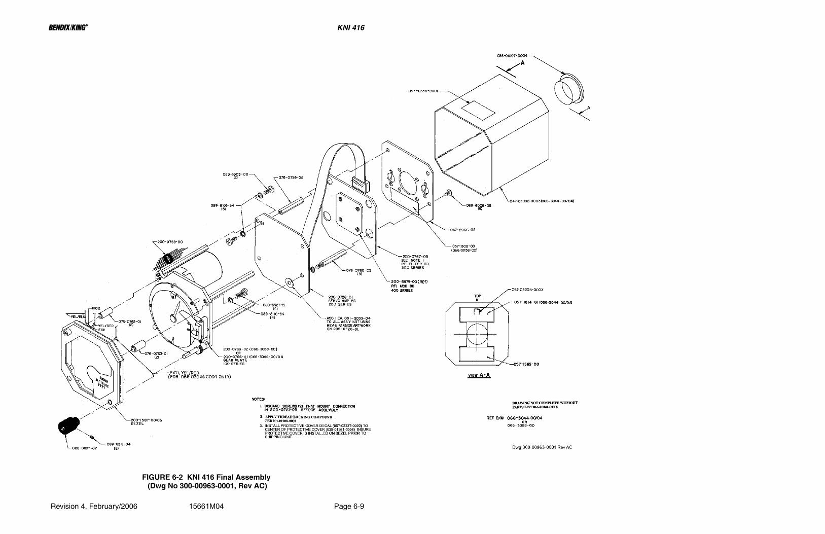
B KNI 416
Revision 4, February/2006 15661M04 Page 6-9
FIGURE 6-2 KNI 416 Final Assembly (Dwg No 300-00963-0001, Rev AC)

B KNI 416
Revision 4, February/2006 15661M04 Page 6-11
FIGURE 6-2A KNI 416 Final Assembly (Dwg No 300-00963-0001, Rev 12) (For Reference Only)

B KNI 416
Revision 4, February/2006 15661M04 Page 6-13
FIGURE 6-3 KNI 416 Final Assembly Schematic (-0001) (Dwg No 002-00287-0001, Rev 9)

B KNI 416
Revision 4, February/2006 15661M04 Page 6-15
FIGURE 6-4 KNI 416 Final Assembly Schematic (-0010) (Dwg No 002-00287-0010, Rev AG)
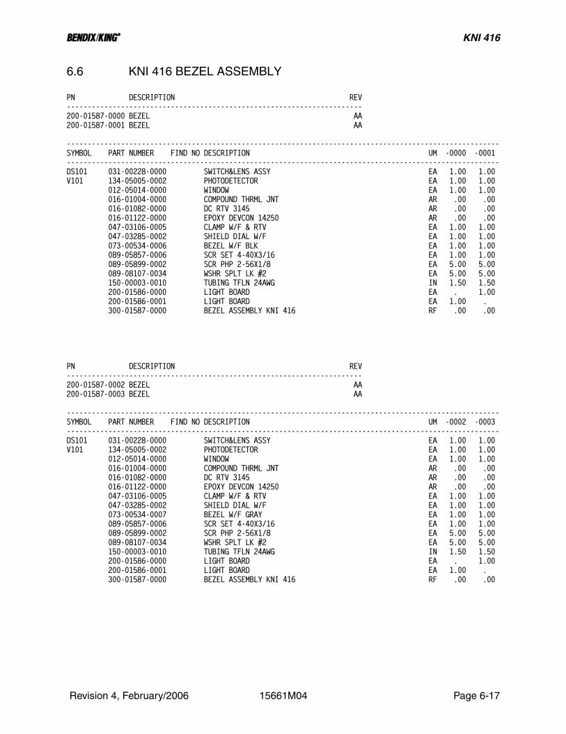
B KNI 416
6.6 KNI 416 BEZEL ASSEMBLY
PN DESCRIPTION REV-----------------------------------------------------------------------200-01587-0000 BEZEL AA200-01587-0001 BEZEL AA
--------------------------------------------------------------------------------------------------------SYMBOL PART NUMBER FIND NO DESCRIPTION UM -0000 -0001--------------------------------------------------------------------------------------------------------DS101 031-00228-0000 SWITCH&LENS ASSY EA 1.00 1.00V101 134-05005-0002 PHOTODETECTOR EA 1.00 1.00 012-05014-0000 WINDOW EA 1.00 1.00 016-01004-0000 COMPOUND THRML JNT AR .00 .00 016-01082-0000 DC RTV 3145 AR .00 .00 016-01122-0000 EPOXY DEVCON 14250 AR .00 .00 047-03106-0005 CLAMP W/F & RTV EA 1.00 1.00 047-03285-0002 SHIELD DIAL W/F EA 1.00 1.00 073-00534-0006 BEZEL W/F BLK EA 1.00 1.00 089-05857-0006 SCR SET 4-40X3/16 EA 1.00 1.00 089-05899-0002 SCR PHP 2-56X1/8 EA 5.00 5.00 089-08107-0034 WSHR SPLT LK #2 EA 5.00 5.00 150-00003-0010 TUBING TFLN 24AWG IN 1.50 1.50 200-01586-0000 LIGHT BOARD EA . 1.00 200-01586-0001 LIGHT BOARD EA 1.00 . 300-01587-0000 BEZEL ASSEMBLY KNI 416 RF .00 .00
PN DESCRIPTION REV-----------------------------------------------------------------------200-01587-0002 BEZEL AA200-01587-0003 BEZEL AA
--------------------------------------------------------------------------------------------------------SYMBOL PART NUMBER FIND NO DESCRIPTION UM -0002 -0003--------------------------------------------------------------------------------------------------------DS101 031-00228-0000 SWITCH&LENS ASSY EA 1.00 1.00V101 134-05005-0002 PHOTODETECTOR EA 1.00 1.00 012-05014-0000 WINDOW EA 1.00 1.00 016-01004-0000 COMPOUND THRML JNT AR .00 .00 016-01082-0000 DC RTV 3145 AR .00 .00 016-01122-0000 EPOXY DEVCON 14250 AR .00 .00 047-03106-0005 CLAMP W/F & RTV EA 1.00 1.00 047-03285-0002 SHIELD DIAL W/F EA 1.00 1.00 073-00534-0007 BEZEL W/F GRAY EA 1.00 1.00 089-05857-0006 SCR SET 4-40X3/16 EA 1.00 1.00 089-05899-0002 SCR PHP 2-56X1/8 EA 5.00 5.00 089-08107-0034 WSHR SPLT LK #2 EA 5.00 5.00 150-00003-0010 TUBING TFLN 24AWG IN 1.50 1.50 200-01586-0000 LIGHT BOARD EA . 1.00 200-01586-0001 LIGHT BOARD EA 1.00 . 300-01587-0000 BEZEL ASSEMBLY KNI 416 RF .00 .00
Revision 4, February/2006 15661M04 Page 6-17
B KNI 416
THIS PAGE IS RESERVED
Revision 4, February/2006 15661M04 Page 6-18

B KNI 416
THE FOLLOWING IS THE PARTS LIST FROM A PREVIOUS MANUAL REVISION AND IS PROVIDED FOR REFERENCE ONLY.
Revision 4, February/2006 15661M04 Page 6-19

B KNI 416
THIS PAGE IS RESERVED
Revision 4, February/2006 15661M04 Page 6-20

B KNI 416
Revision 4, February/2006 15661M04 Page 6-21
FIGURE 6-5 KNI 416 Bezel Assembly (Dwg No 300-01587-0000, Rev AA)

B KNI 416
Revision 4, February/2006 15661M04 Page 6-23
FIGURE 6-5A KNI 416 Bezel Assembly (Dwg No 300-01587-0000, Rev 7) (For Reference Only)

B KNI 416
6.7 KNI 416 LIGHT BOARD
PN DESCRIPTION REV-----------------------------------------------------------------------200-01586-0000 LIGHT BOARD 1200-01586-0001 LIGHT BOARD 1
--------------------------------------------------------------------------------------------------------SYMBOL PART NUMBER FIND NO DESCRIPTION UM -0000 -0001--------------------------------------------------------------------------------------------------------DS102 037-00012-0001 LAMP MIN T-1 5V EA . 1.00DS102 037-00013-0001 LMP 6838 T1 28V EA 1.00 . DS103 037-00012-0001 LAMP MIN T-1 5V EA . 1.00DS103 037-00013-0001 LMP 6838 T1 28V EA 1.00 . DS104 037-00012-0001 LAMP MIN T-1 5V EA . 1.00DS104 037-00013-0001 LMP 6838 T1 28V EA 1.00 . DS105 037-00012-0001 LAMP MIN T-1 5V EA . 1.00DS105 037-00013-0001 LMP 6838 T1 28V EA 1.00 . DS106 037-00012-0001 LAMP MIN T-1 5V EA . 1.00DS106 037-00013-0001 LMP 6838 T1 28V EA 1.00 . 009-05436-0000 LIGHTING BD EA 1.00 1.00 010-00050-0000 TERM STANDOFF .350 EA 2.00 2.00 047-03284-0001 BRACKET LGT BD W/F EA 1.00 1.00 088-00084-0008 FLTR LAMP LT BLU EA 5.00 5.00 092-05003-0001 EYE ROLL .059X.125 EA 2.00 2.00
Revision 4, February/2006 15661M04 Page 6-25

B KNI 416
THIS PAGE IS RESERVED
Revision 4, February/2006 15661M04 Page 6-26

B KNI 416
Revision 4, February/2006 15661M04 Page 6-27
FIGURE 6-6 KNI 416 Light Board Assembly (Dwg No 300-01586-0000, Rev AA)

B KNI 416
Revision 4, February/2006 15661M04 Page 6-29
FIGURE 6-6A KNI 416 Light Board Assembly (Dwg No 300-01586-0000, Rev 3) (For Reference Only)

B KNI 416
6.8 KNI 416 GEAR PLATE ASSEMBLY
PN DESCRIPTION REV-----------------------------------------------------------------------200-00766-0001 GEAR PLATE ASSY BE
-------------------------------------------------------------------------------------------------SYMBOL PART NUMBER FIND NO DESCRIPTION UM -0001-------------------------------------------------------------------------------------------------B101 200-00770-0001 MTR & FLTR BOX EA 1.00CR101 007-06047-0000 DIO S 1N4005 EA 1.00DS107 200-00622-0003 FLAG MCHNSM ASSY EA 1.00Q101 007-00208-0001 XSTR NPN MJE800 EA 1.00Q102 007-00276-0002 XSTR MJE181 EA 1.00Q103 007-00276-0003 XSTR MJE171 EA 1.00Q104 007-00276-0002 XSTR MJE181 EA 1.00R101 133-00107-0001 RES 5K 10% EA 1.00R102 133-00107-0001 RES 5K 10% EA 1.00R104 132-00059-0000 RES WW 33 3W 5% EA 1.00R105 132-00059-0000 RES WW 33 3W 5% EA 1.00R106 131-00123-0023 RES CF 12K QW 5% EA 1.00R107 131-00103-0023 RES CF 10K QW 5% EA 1.00R108 131-00101-0023 RES CF 100 QW 5% EA 1.00R109 132-00106-0053 RES WW 82 2.25W 5% EA 1.00S101 031-00236-0000 SWITCH, PUSHBUTTON, DPDT EA 1.00 008-00045-0001 TERM EA 2.00 010-00019-0091 TERM STDF WHT EA 7.00 010-00019-0094 TERM STDF WHT EA 7.00 010-00021-0093 TERM FDTH WHT EA 4.00 016-01004-0000 COMPOUND THRML JNT AR 1.00 016-01007-0009 LOCTITE 242 AR 1.00 026-00001-0000 WIRE, CU, 26AWG, TINNED IN 7.20 029-00304-0000 GEAR SPUR 64P EA 1.00 029-00510-0003 GEAR SPUR ASSMBLD EA 1.00 029-00511-0004 GEAR ANTI-BACKLASH EA 1.00 047-03109-0001 POINTER W/F EA 1.00 047-03280-0001 BLOCK W/ROLL PIN EA 1.00 047-03281-0001 SHIELD BKGD W/F EA 1.00 047-03282-0001 BRKT HEATSINK W/F EA 1.00 047-03283-0001 DIAL ALT W/F EA 1.00 047-03286-0001 PLT GEAR MTG W/F EA 1.00 047-06648-0000 SPACER FLAG MECH EA 1.00 073-00034-0000 MOUNTING LUG EA 4.00 076-00758-0001 SPACER SHIELD W/F EA 5.00 076-00759-0003 SPACER W/F EA 4.00 076-00764-0000 SHAFT PLXGLS EA 1.00 076-00765-0001 HOUSING AL EA 1.00 076-00766-0001 CLAMP AL EA 1.00 076-00771-0000 SHAFT EA 1.00 078-00075-0000 SPRING SWITCH EA 1.00 089-02188-0022 NUT LCOK 4-40 EA 1.00 089-05432-0004 SCR, MACH, 2-56, FH 82, PH, SS300, PSVT, 1/4 LG EA 3.00 089-05436-0005 SCR, MACH, 4-40, FH 82, PH, SS300, PSVT, 5/16 LG EA 2.00 089-05899-0005 SCR PHP 2-56X5/16 EA 4.00 089-05903-0005 SCR PHP 4-40X5/16 EA 2.00 089-05903-0006 SCR PHP 4-40X3/8 EA 9.00 089-06004-0003 SCR FHP 2-56X3/16 EA 2.00 089-06024-0006 SCR SHC 4-40X3/8 EA 5.00 089-06077-0003 SCR PHP 2-56X3/16 EA 5.00 089-06179-0004 SCR SET 2-56X1/8 EA 2.00 089-08025-0030 WSHR FLT STD #4 EA 2.00 089-08079-0030 WSHR FLT STD .256 AR 1.00 089-08107-0034 WSHR SPLT LK #2 EA 6.00 089-08109-0034 WSHR SPLT LK #4 EA 16.00 089-08159-0000 WSHR THR .130 EA 1.00
Revision 4, February/2006 15661M04 Page 6-31

B KNI 416
PN DESCRIPTION REV-----------------------------------------------------------------------200-00766-0001 GEAR PLATE ASSY BE
-------------------------------------------------------------------------------------------------SYMBOL PART NUMBER FIND NO DESCRIPTION UM -0001------------------------------------------------------------------------------------------------- 089-08209-0001 WSHR PRPH LK .136 EA 4.00 089-08306-0000 WASHER THRUST EA 2.00 090-00033-0003 SPRING WASHER EA 2.00 090-00041-0001 RTNR RNG .250 DI EA 1.00 090-00186-0000 RETAINER RING EA 1.00 091-00262-0001 INSUL WASHER EA 4.00 147-00017-0000 BEARING FLNG EA 1.00 150-00005-0010 TUBING TFLN 20AWG IN 6.00 200-00771-0001 FLAG ASSY EA 1.00 300-01001-0001 GEAR PLATE RF .00
Revision 4, February/2006 15661M04 Page 6-32
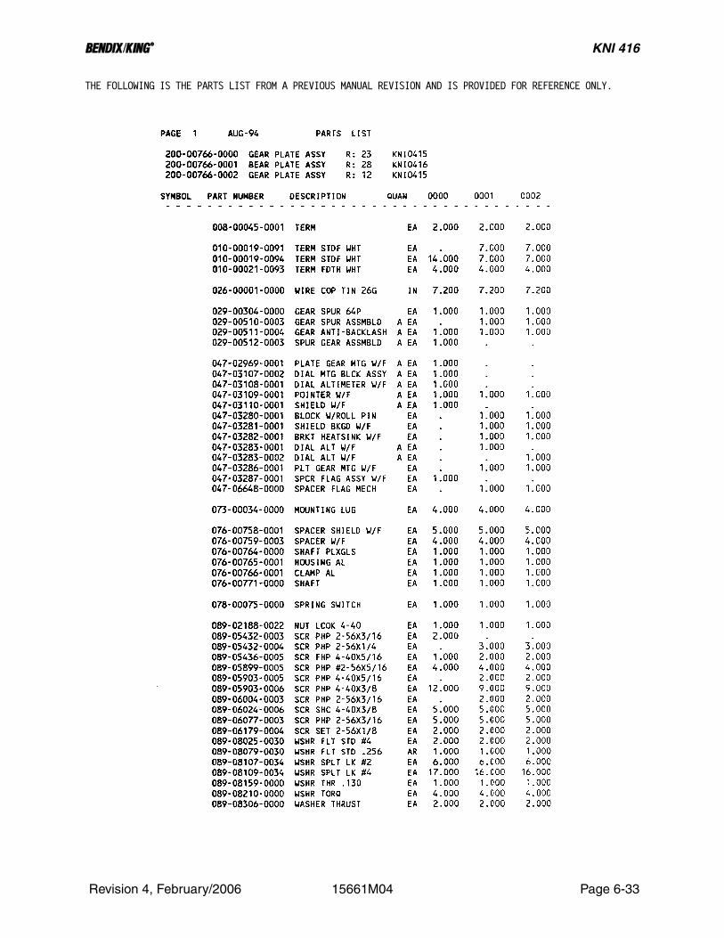
B KNI 416
THE FOLLOWING IS THE PARTS LIST FROM A PREVIOUS MANUAL REVISION AND IS PROVIDED FOR REFERENCE ONLY.
Revision 4, February/2006 15661M04 Page 6-33

B KNI 416
THIS PAGE IS RESERVED
Revision 4, February/2006 15661M04 Page 6-34

B KNI 416
Revision 4, February/2006 15661M04 Page 6-35
FIGURE 6-7 KNI 416 Gear Plate Assembly (Dwg No 300-01001-0001, Rev AA, Sht 1 of 2)
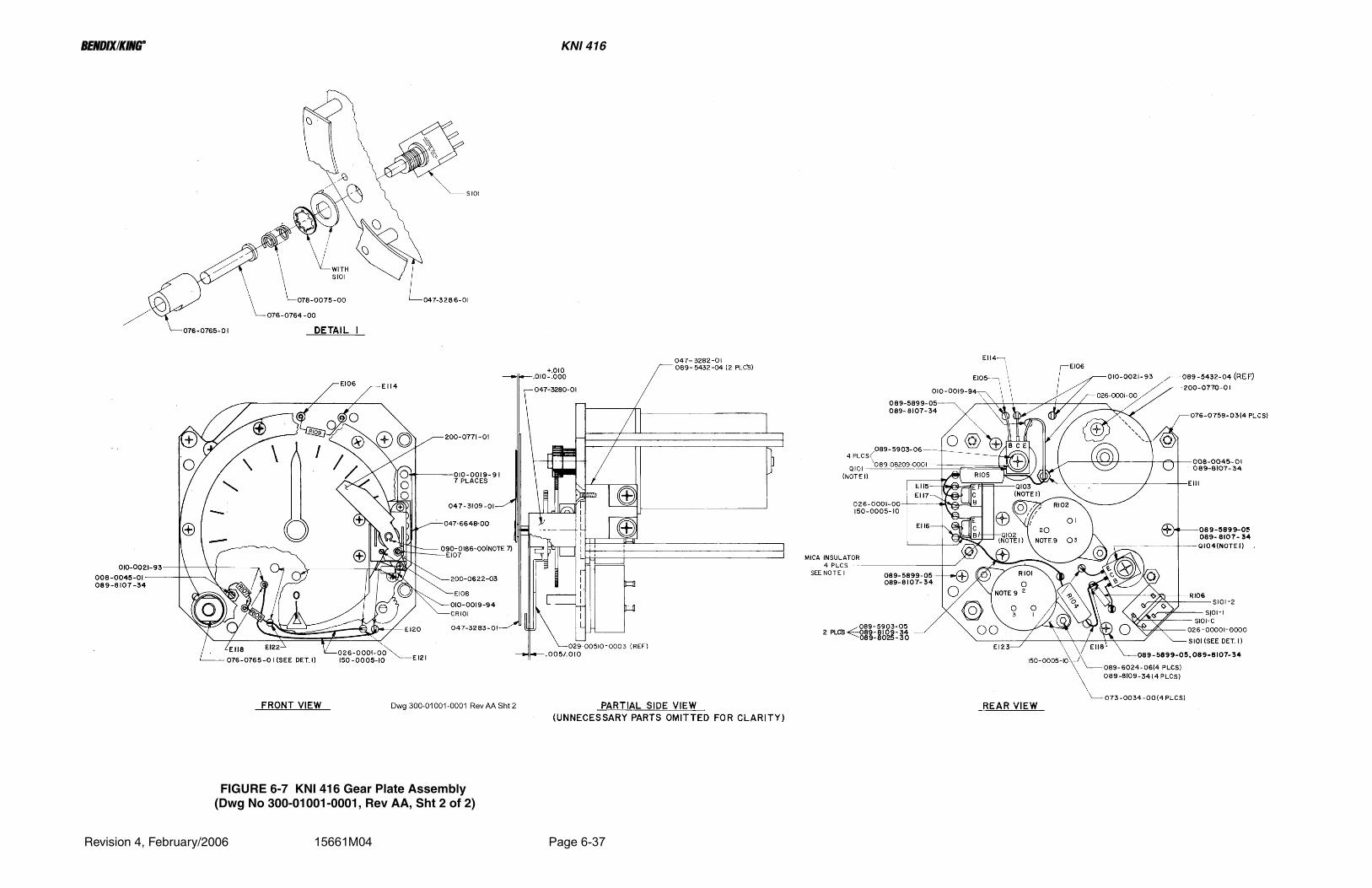
B KNI 416
Revision 4, February/2006 15661M04 Page 6-37
FIGURE 6-7 KNI 416 Gear Plate Assembly (Dwg No 300-01001-0001, Rev AA, Sht 2 of 2)

B KNI 416
Revision 4, February/2006 15661M04 Page 6-39
FIGURE 6-7A KNI 416 Gear Plate Assembly (Dwg No 300-01001-0001, Rev 17, Sht 1 of 2) (For Reference Only)

B KNI 416
Revision 4, February/2006 15661M04 Page 6-41
FIGURE 6-7A KNI 416 Gear Plate Assembly (Dwg No 300-01001-0001, Rev 17, Sht 2 of 2) (For Reference Only)

B KNI 416
6.9 KNI 416 MOTOR AND FILTER BOX
PN DESCRIPTION REV-----------------------------------------------------------------------200-00770-0001 MTR & FLTR BOX 6
-------------------------------------------------------------------------------------------------SYMBOL PART NUMBER FIND NO DESCRIPTION UM -0001-------------------------------------------------------------------------------------------------REF1 300-01005-0000 MOTOR & FILTER BOX RF .00 029-00300-0003 GEAR DR 64P .1880 EA 1.00 090-00052-0000 ROLL PIN .375 EA 1.00 148-05029-0001 MOTOR DC W/GR HD EA 1.00
Revision 4, February/2006 15661M04 Page 6-43

B KNI 416
THIS PAGE IS RESERVED
Revision 4, February/2006 15661M04 Page 6-44

B KNI 416
Revision 4, February/2006 15661M04 Page 6-45
FIGURE 6-8 KNI 416 Motor & Filter Box Assembly (Dwg No 300-01005-0000, Rev 7)

B KNI 416
Revision 4, February/2006 15661M04 Page 6-47
FIGURE 6-8A KNI 416 Motor & Filter Box Assembly (Dwg No 300-01005-0000, Rev 6) (For Reference Only)

B KNI 416
6.10 KNI 416 FLAG MECHANICAL ASSEMBLY
PN DESCRIPTION REV-----------------------------------------------------------------------200-00622-0003 FLAG MCHNSM ASSY AA
-------------------------------------------------------------------------------------------------SYMBOL PART NUMBER FIND NO DESCRIPTION UM -0003-------------------------------------------------------------------------------------------------REF1 300-00819-0003 FLAG MECHANISM ASSEMBLY KNI 416 RF .00 012-01021-0004 TAPE ELEC 1/4 WD IN 1.00 016-01114-0000 EPXY TRA-CAST 3103 AR .00 019-02185-0000 COIL FLG MCH 1750T EA 1.00 047-02847-0006 POLE .430 W/F EA 1.00 047-02847-0009 POLE .380 W/F EA 1.00 047-02848-0001 SPACER POLE W/F EA 2.00 088-00344-0000 HSG FLAG EA 1.00 088-00345-0001 COVER FLAG EA 1.00 089-05517-0006 SCR FLHP 1-64X3/8 EA 2.00
Revision 4, February/2006 15661M04 Page 6-49

B KNI 416
THIS PAGE IS RESERVED
Revision 4, February/2006 15661M04 Page 6-50
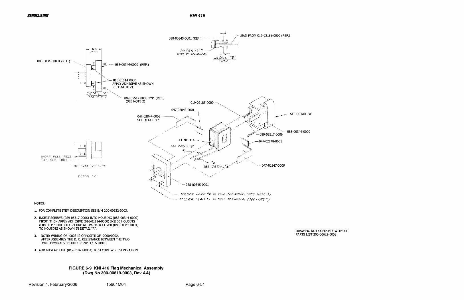
B KNI 416
Revision 4, February/2006 15661M04 Page 6-51
FIGURE 6-9 KNI 416 Flag Mechanical Assembly (Dwg No 300-00819-0003, Rev AA)
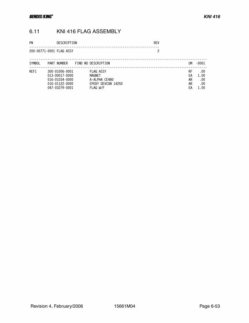
B KNI 416
6.11 KNI 416 FLAG ASSEMBLY
PN DESCRIPTION REV-----------------------------------------------------------------------200-00771-0001 FLAG ASSY 2
-------------------------------------------------------------------------------------------------SYMBOL PART NUMBER FIND NO DESCRIPTION UM -0001-------------------------------------------------------------------------------------------------REF1 300-01006-0001 FLAG ASSY RF .00 013-00017-0000 MAGNET EA 1.00 016-01034-0000 A-ALPHA CE480 AR .00 016-01122-0000 EPOXY DEVCON 14250 AR .00 047-03279-0001 FLAG W/F EA 1.00
Revision 4, February/2006 15661M04 Page 6-53

B KNI 416
THIS PAGE IS RESERVED
Revision 4, February/2006 15661M04 Page 6-54

B KNI 416
Revision 4, February/2006 15661M04 Page 6-55
FIGURE 6-10 KNI 416 Flag Assembly (Dwg No 300-01006-0001, Rev 3)
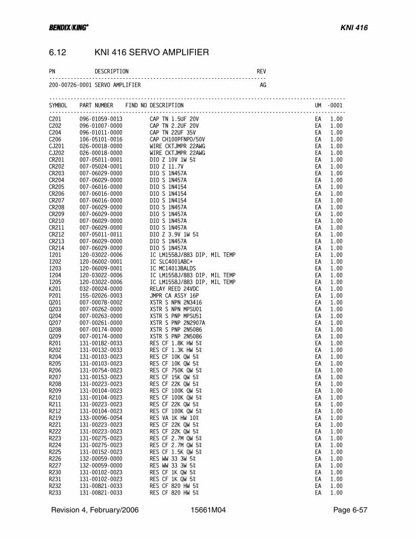
B KNI 416
6.12 KNI 416 SERVO AMPLIFIER
PN DESCRIPTION REV-----------------------------------------------------------------------200-00726-0001 SERVO AMPLIFIER AG
-------------------------------------------------------------------------------------------------SYMBOL PART NUMBER FIND NO DESCRIPTION UM -0001-------------------------------------------------------------------------------------------------C201 096-01059-0013 CAP TN 1.5UF 20V EA 1.00C202 096-01007-0000 CAP TN 2.2UF 20V EA 1.00C204 096-01011-0000 CAP TN 22UF 35V EA 1.00C206 106-05101-0016 CAP CH100PFNPO/50V EA 1.00CJ201 026-00018-0000 WIRE CKTJMPR 22AWG EA 1.00CJ202 026-00018-0000 WIRE CKTJMPR 22AWG EA 1.00CR201 007-05011-0001 DIO Z 10V 1W 5% EA 1.00CR202 007-05024-0001 DIO Z 11.7V EA 1.00CR203 007-06029-0000 DIO S 1N457A EA 1.00CR204 007-06029-0000 DIO S 1N457A EA 1.00CR205 007-06016-0000 DIO S 1N4154 EA 1.00CR206 007-06016-0000 DIO S 1N4154 EA 1.00CR207 007-06016-0000 DIO S 1N4154 EA 1.00CR208 007-06029-0000 DIO S 1N457A EA 1.00CR209 007-06029-0000 DIO S 1N457A EA 1.00CR210 007-06029-0000 DIO S 1N457A EA 1.00CR211 007-06029-0000 DIO S 1N457A EA 1.00CR212 007-05011-0011 DIO Z 3.9V 1W 5% EA 1.00CR213 007-06029-0000 DIO S 1N457A EA 1.00CR214 007-06029-0000 DIO S 1N457A EA 1.00I201 120-03022-0006 IC LM1558J/883 DIP, MIL TEMP EA 1.00I202 120-06002-0001 IC SLC4001ABC+ EA 1.00I203 120-06009-0001 IC MC14013BALDS EA 1.00I204 120-03022-0006 IC LM1558J/883 DIP, MIL TEMP EA 1.00I205 120-03022-0006 IC LM1558J/883 DIP, MIL TEMP EA 1.00K201 032-00024-0000 RELAY REED 24VDC EA 1.00P201 155-02026-0003 JMPR CA ASSY 16P EA 1.00Q201 007-00078-0002 XSTR S NPN 2N3416 EA 1.00Q203 007-00262-0000 XSTR S NPN MPSU01 EA 1.00Q204 007-00263-0000 XSTR S PNP MPSU51 EA 1.00Q207 007-00261-0000 XSTR S PNP 2N2907A EA 1.00Q208 007-00174-0000 XSTR S PNP 2N5086 EA 1.00Q209 007-00174-0000 XSTR S PNP 2N5086 EA 1.00R201 131-00182-0033 RES CF 1.8K HW 5% EA 1.00R202 131-00132-0033 RES CF 1.3K HW 5% EA 1.00R204 131-00103-0023 RES CF 10K QW 5% EA 1.00R205 131-00103-0023 RES CF 10K QW 5% EA 1.00R206 131-00754-0023 RES CF 750K QW 5% EA 1.00R207 131-00153-0023 RES CF 15K QW 5% EA 1.00R208 131-00223-0023 RES CF 22K QW 5% EA 1.00R209 131-00104-0023 RES CF 100K QW 5% EA 1.00R210 131-00104-0023 RES CF 100K QW 5% EA 1.00R211 131-00223-0023 RES CF 22K QW 5% EA 1.00R212 131-00104-0023 RES CF 100K QW 5% EA 1.00R219 133-00096-0054 RES VA 1K HW 10% EA 1.00R221 131-00223-0023 RES CF 22K QW 5% EA 1.00R222 131-00223-0023 RES CF 22K QW 5% EA 1.00R223 131-00275-0023 RES CF 2.7M QW 5% EA 1.00R224 131-00275-0023 RES CF 2.7M QW 5% EA 1.00R225 131-00152-0023 RES CF 1.5K QW 5% EA 1.00R226 132-00059-0000 RES WW 33 3W 5% EA 1.00R227 132-00059-0000 RES WW 33 3W 5% EA 1.00R230 131-00102-0023 RES CF 1K QW 5% EA 1.00R231 131-00102-0023 RES CF 1K QW 5% EA 1.00R232 131-00821-0033 RES CF 820 HW 5% EA 1.00R233 131-00821-0033 RES CF 820 HW 5% EA 1.00
Revision 4, February/2006 15661M04 Page 6-57

B KNI 416
PN DESCRIPTION REV-----------------------------------------------------------------------200-00726-0001 SERVO AMPLIFIER AG
-------------------------------------------------------------------------------------------------SYMBOL PART NUMBER FIND NO DESCRIPTION UM -0001-------------------------------------------------------------------------------------------------R234 131-00103-0023 RES CF 10K QW 5% EA 1.00R235 131-00103-0023 RES CF 10K QW 5% EA 1.00R236 131-00123-0023 RES CF 12K QW 5% EA 1.00R237 131-00472-0023 RES CF 4.7K QW 5% EA 1.00R238 131-00472-0023 RES CF 4.7K QW 5% EA 1.00R239 131-00822-0023 RES CF 8.2K QW 5% EA 1.00R240 131-00103-0023 RES CF 10K QW 5% EA 1.00R241 131-00103-0023 RES CF 10K QW 5% EA 1.00R242 131-00684-0023 RES CF 680K QW 5% EA 1.00R243 131-00684-0023 RES CF 680K QW 5% EA 1.00R244 131-00103-0023 RES CF 10K QW 5% EA 1.00R245 131-00152-0023 RES CF 1.5K QW 5% EA 1.00R246 131-00153-0023 RES CF 15K QW 5% EA 1.00R247 131-00203-0023 RES CF 20K QW 5% EA 1.00R248 131-00302-0023 RES CF 3K QW 5% EA 1.00R249 131-00472-0023 RES CF 4.7K QW 5% EA 1.00R250 131-00103-0023 RES CF 10K QW 5% EA 1.00R252 136-07502-0072 RES PF 75K QW 1% EA 1.00R254 136-01002-0072 RES PF 10K QW 1% EA 1.00R255 131-00333-0023 RES CF 33K QW 5% EA 1.00R256 136-02321-0072 RES PF 2.32K QW 1% EA 1.00R257 133-00096-0053 RES VA 500 HW 10% EA 1.00R258 136-01741-0072 RES PF 1.74K QW 1% EA 1.00R259 131-00151-0023 RES CF 150 QW 5% EA 1.00R261 133-00096-0028 RES VA 500 HW 10% EA 1.00R262 136-01780-0062 RES PF 178 EW 1% EA 1.00R263 136-01582-0072 RES PF 15.8K QW 1% EA 1.00R264 133-00096-0030 RES VA 2K HW 10% EA 1.00TP201 010-00050-0000 TERM STANDOFF .350 EA 1.00TP202 010-00050-0000 TERM STANDOFF .350 EA 1.00TP203 010-00050-0000 TERM STANDOFF .350 EA 1.00TP204 010-00050-0000 TERM STANDOFF .350 EA 1.00TP205 010-00050-0000 TERM STANDOFF .350 EA 1.00TP206 010-00050-0000 TERM STANDOFF .350 EA 1.00TP207 010-00050-0000 TERM STANDOFF .350 EA 1.00TP208 010-00050-0000 TERM STANDOFF .350 EA 1.00TP209 010-00050-0000 TERM STANDOFF .350 EA 1.00TP210 010-00050-0000 TERM STANDOFF .350 EA 1.00TP211 010-00050-0000 TERM STANDOFF .350 EA 1.00TP212 010-00050-0000 TERM STANDOFF .350 EA 1.00TP213 010-00050-0000 TERM STANDOFF .350 EA 1.00TP214 010-00050-0000 TERM STANDOFF .350 EA 1.00TP215 010-00050-0000 TERM STANDOFF .350 EA 1.00TP216 010-00050-0000 TERM STANDOFF .350 EA 1.00TP217 010-00050-0000 TERM STANDOFF .350 EA 1.00TP218 010-00050-0000 TERM STANDOFF .350 EA 1.00TP219 010-00050-0000 TERM STANDOFF .350 EA 1.00 002-00287-0010 KNI415/416 ALTIMETER INDICATOR RF .00 009-05593-0000 PC BD SERVO AMP EA 1.00 016-01082-0000 DC RTV 3145 AR 1.00 150-00004-0010 TUBING TFLN 22AWG AR 1.00 192-00726-0001 KNI 416 SERVO AMPLIFIER BD ASSY RF .00 300-00964-0001 SERVO AMPLIFIER KNI 415/416 RF .00
Revision 4, February/2006 15661M04 Page 6-58
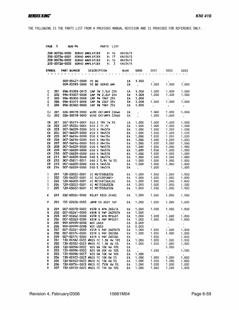
B KNI 416
THE FOLLOWING IS THE PARTS LIST FROM A PREVIOUS MANUAL REVISION AND IS PROVIDED FOR REFERENCE ONLY.
Revision 4, February/2006 15661M04 Page 6-59

B KNI 416
Revision 4, February/2006 15661M04 Page 6-60

B KNI 416
Revision 4, February/2006 15661M04 Page 6-61

B KNI 416
THIS PAGE IS RESERVED
Revision 4, February/2006 15661M04 Page 6-62

B KNI 416
Revision 4, February/2006 15661M04 Page 6-63
FIGURE 6-11 KNI 416 Servo Amplifier Assembly (Dwg No 300-00964-0001, Rev AD)
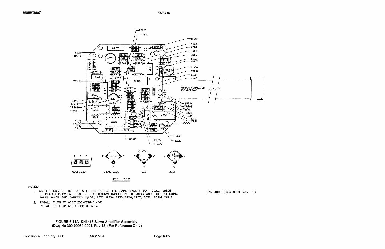
B KNI 416
Revision 4, February/2006 15661M04 Page 6-65
FIGURE 6-11A KNI 416 Servo Amplifier Assembly (Dwg No 300-00964-0001, Rev 13) (For Reference Only)

B KNI 416
6.13 KNI 416 RFI FILTER BOARD
PN DESCRIPTION REV-----------------------------------------------------------------------200-00767-0003 RFI FILTER ASSY AB
-------------------------------------------------------------------------------------------------SYMBOL PART NUMBER FIND NO DESCRIPTION UM -0003-------------------------------------------------------------------------------------------------C314 096-01011-0000 CAP TN 22UF 35V EA 1.00C315 096-01010-0000 CAP TN 4.7UF 50V EA 1.00C316 096-01014-0000 CAP TN 40UF 10V EA 1.00C317 096-01063-0000 CAP TN 3.9UF75V10% EA 1.00C318 097-00238-1135 CAP AL, LOW LEAKAGE CURRENT, 50V 10 UF EA 1.00C319 097-00238-1135 CAP AL, LOW LEAKAGE CURRENT, 50V 10 UF EA 1.00C320 096-01015-0000 CAP TN 10UF 20V EA 1.00C321 106-05101-0016 CAP CH100PFNPO/50V EA 1.00C322 106-05101-0016 CAP CH100PFNPO/50V EA 1.00I301 120-03022-0006 IC LM1558J/883 DIP, MIL TEMP EA 1.00J301 033-00092-0006 IC DIP SCKT 16C EA 1.00J4151 030-02194-0004 CONN PLUG 19 PIN M EA 1.00L301 013-00006-0002 FERR BEAD EA 1.00L302 013-00006-0002 FERR BEAD EA 1.00L303 013-00006-0002 FERR BEAD EA 1.00L304 013-00006-0002 FERR BEAD EA 1.00L305 013-00006-0002 FERR BEAD EA 1.00L306 013-00006-0002 FERR BEAD EA 1.00L307 013-00006-0002 FERR BEAD EA 1.00L308 013-00006-0002 FERR BEAD EA 1.00L309 013-00006-0002 FERR BEAD EA 1.00L310 013-00006-0002 FERR BEAD EA 1.00L311 013-00006-0002 FERR BEAD EA 1.00L312 013-00006-0002 FERR BEAD EA 1.00L313 013-00006-0002 FERR BEAD EA 1.00L314 013-00006-0002 FERR BEAD EA 1.00Q301 007-00261-0000 XSTR S PNP 2N2907A EA 1.00R301 131-00223-0023 RES CF 22K QW 5% EA 1.00R302 131-00223-0023 RES CF 22K QW 5% EA 1.00R303 136-05112-0072 RES PF 51.1K QW 1% EA 1.00R304 136-01052-0072 RES PF 10.5K QW 1% EA 1.00R305 131-00152-0023 RES CF 1.5K QW 5% EA 1.00R306 131-00103-0023 RES CF 10K QW 5% EA 1.00R307 131-00680-0023 RES CF 68 QW 5% EA 1.00REF1 002-00287-0010 KNI415/416 ALTIMETER INDICATOR RF .00REF2 300-01002-0010 RFI BOARD KNI 415, KNI 416 RF .00 009-05596-0010 PC BD RFI FILTER EA 1.00 012-01005-0007 TAPE MYLAR 1.5 W IN 1.00 016-01082-0000 DC RTV 3145 AR 1.00 076-00770-0001 SPACER W/F EA 4.00 089-05903-0004 SCR PHP 4-40X1/4 EA 2.00 089-05903-0007 SCR PHP 4-40X7/16 EA 4.00 089-08109-0034 WSHR SPLT LK #4 EA 4.00 150-00004-0010 TUBING TFLN 22AWG AR 1.00 192-00767-0003 KNI 416 RFI FILTER BD ASSY RF .00 200-06979-0000 RFI MOD BD EA 1.00
Revision 4, February/2006 15661M04 Page 6-67

B KNI 416
THIS PAGE IS RESERVED
Revision 4, February/2006 15661M04 Page 6-68

B KNI 416
THE FOLLOWING IS THE PARTS LIST FROM A PREVIOUS MANUAL REVISION AND IS PROVIDED FOR REFERENCE ONLY.
Revision 4, February/2006 15661M04 Page 6-69

B KNI 416
THE FOLLOWING IS THE PARTS LIST FROM A PREVIOUS MANUAL REVISION AND IS PROVIDED FOR REFERENCE ONLY.
Revision 4, February/2006 15661M04 Page 6-70
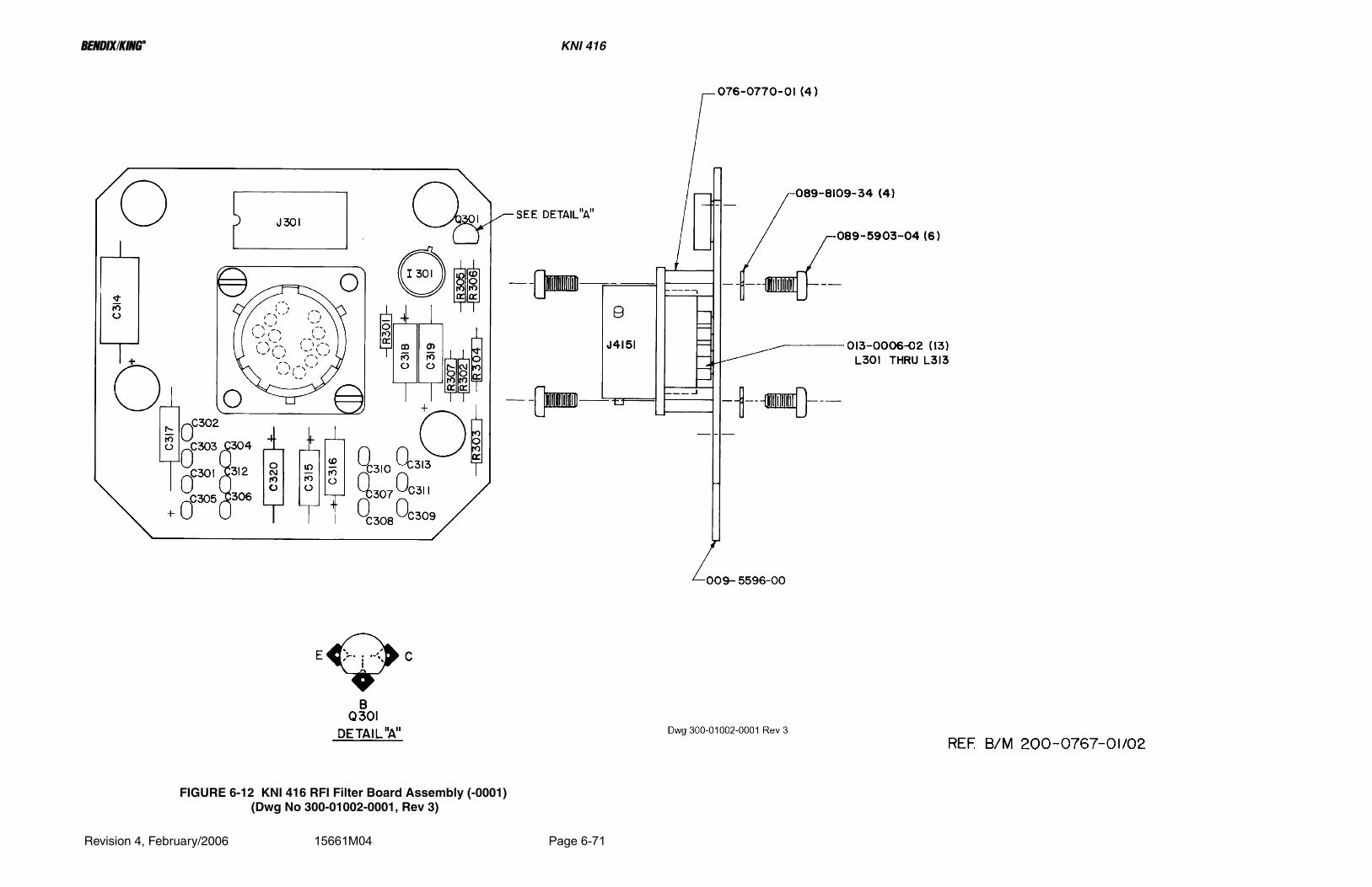
B KNI 416
Revision 4, February/2006 15661M04 Page 6-71
FIGURE 6-12 KNI 416 RFI Filter Board Assembly (-0001) (Dwg No 300-01002-0001, Rev 3)

B KNI 416
Revision 4, February/2006 15661M04 Page 6-73
FIGURE 6-13 KNI 416 RFI Filter Board Assembly (-0010) (Dwg No 300-01002-0010, Rev AB)

B KNI 416
Revision 4, February/2006 15661M04 Page 6-75
FIGURE 6-13A KNI 416 RFI Filter Board Assembly (Dwg No 300-01002-0010, Rev 5) (For Reference Only)

B KNI 416
6.14 KNI 416 RFI MOD BOARD
PN DESCRIPTION REV-----------------------------------------------------------------------200-06979-0000 RFI MOD BD AA
-------------------------------------------------------------------------------------------------SYMBOL PART NUMBER FIND NO DESCRIPTION UM -0000-------------------------------------------------------------------------------------------------C401 111-00001-0015 CAP CR 330PF 50V EA 1.00C402 111-00001-0015 CAP CR 330PF 50V EA 1.00C403 111-00001-0015 CAP CR 330PF 50V EA 1.00C404 111-00001-0015 CAP CR 330PF 50V EA 1.00C405 111-00001-0015 CAP CR 330PF 50V EA 1.00C406 111-00001-0015 CAP CR 330PF 50V EA 1.00C407 111-00001-0015 CAP CR 330PF 50V EA 1.00C408 111-00001-0015 CAP CR 330PF 50V EA 1.00C409 111-00001-0015 CAP CR 330PF 50V EA 1.00C410 111-00001-0015 CAP CR 330PF 50V EA 1.00C411 111-00001-0015 CAP CR 330PF 50V EA 1.00C412 111-00001-0015 CAP CR 330PF 50V EA 1.00C413 111-00001-0015 CAP CR 330PF 50V EA 1.00C414 111-00001-0015 CAP CR 330PF 50V EA 1.00REF1 002-00287-0010 KNI415/416 ALTIMETER INDICATOR RF .00REF2 300-06979-0000 RFI MOD BD ASSY RF .00 009-06979-0000 PC BD RFI MOD EA 1.00 076-00248-0004 SPACER .100 EA 4.00 192-06979-0000 KNI 415 RFI MOD BD ASSY RF .00
Revision 4, February/2006 15661M04 Page 6-77

B KNI 416
THIS PAGE IS RESERVED
Revision 4, February/2006 15661M04 Page 6-78

B KNI 416
Revision 4, February/2006 15661M04 Page 6-79
FIGURE 6-14 KNI 416 RFI Mod Board Assembly (Dwg No 300-06979-0000, Rev 3)

B KNI 416
6.15 KNI 416 WIRING HARNESS
PN DESCRIPTION REV-----------------------------------------------------------------------200-00768-0000 WIRING HARNESS 8
-------------------------------------------------------------------------------------------------SYMBOL PART NUMBER FIND NO DESCRIPTION UM -0000-------------------------------------------------------------------------------------------------REF1 002-00287-0010 KNI415/416 ALTIMETER INDICATOR RF .00REF2 300-01003-0000 WIRING HARNESS KNI 415/416S/N 1400 AND BELOW RF .00 012-01006-0000 LACING CORD 18DR AR .00 025-00018-0000 WIRE 26 BLK IN 8.75 025-00018-0001 WIRE 26 BK/BN IN 3.00 025-00018-0002 WIRE 26 BK/RD IN 7.00 025-00018-0011 WIRE 26 BRN IN 9.75 025-00018-0012 WIRE 26 BN/RD IN 10.25 025-00018-0013 WIRE 26 BN/OR IN 11.00 025-00018-0022 WIRE 26 RED IN 7.75 025-00018-0023 WIRE 26 RD/OR IN 7.50 025-00018-0025 WIRE 26 RD/GN IN 8.50 025-00018-0026 WIRE 26 RD/BU IN 12.00 025-00018-0028 WIRE 26 RD/GY IN 8.75 025-00018-0029 WIRE 26 RD/WH IN 10.25 025-00018-0031 WIRE 26 OR/BN IN 11.00 025-00018-0033 WIRE 26 ORG IN 9.00 025-00018-0034 WIRE 26 OR/YL IN 4.00 025-00018-0035 WIRE 26 OR/GN IN 9.00 025-00018-0036 WIRE 26 OR/BU IN 7.50 025-00018-0039 WIRE 26 OR/WH IN 7.00 025-00018-0040 WIRE 26 YL/BK IN 7.00 025-00018-0042 WIRE 26 YL/RD IN 7.50 025-00018-0049 WIRE 26 YL/WH IN 10.25 025-00018-0055 WIRE 26 GRN IN 9.50
Revision 4, February/2006 15661M04 Page 6-81

B KNI 416
THIS PAGE IS RESERVED
Revision 4, February/2006 15661M04 Page 6-82

B KNI 416
THE FOLLOWING IS THE PARTS LIST FROM A PREVIOUS MANUAL REVISION AND IS PROVIDED FOR REFERENCE ONLY.
Revision 4, February/2006 15661M04 Page 6-83

B KNI 416
THIS PAGE IS RESERVED
Revision 4, February/2006 15661M04 Page 6-84

B KNI 416
Revision 4, February/2006 15661M04 Page 6-85
FIGURE 6-15 KNI 416 Wiring Harness Assembly (Dwg No 300-01003-0000, Rev AA, Sheet 1 of 2)

B KNI 416
Revision 4, February/2006 15661M04 Page 6-87
FIGURE 6-15 KNI 416 Wiring Harness Assembly (Dwg No 300-01003-0000, Rev AA, Sheet 2 of 2)

B KNI 416
Revision 4, February/2006 15661M04 Page 6-89
FIGURE 6-15A KNI 416 Wiring Harness Assembly (Dwg No 300-01003-0000, Rev 9, Sheet 1 of 2) (For Reference Only)

B KNI 416
Revision 4, February/2006 15661M04 Page 6-91
FIGURE 6-15A KNI 416 Wiring Harness Assembly (Dwg No 300-01003-0000, Rev 9, Sheet 2 of 2) (For Reference Only)