kneealign 2 system - amazon web services€¦ · · 2017-03-29kneealign® 2 system . table of...
TRANSCRIPT

Surgical Technique ManualTibia and Distal Femur Navigation
KneeAlign® 2 System

Table of Contents
SETUP Step 1 Install Sensor Battery ..................................................... 1
Step 2 Confirm Sensor ID........................................................... 1
Step 3 Attach Bracket .................................................................. 2
Step 4 Hold Horizontally ............................................................ 2
Step 5 Hold Vertically ................................................................... 3
Step 6 Verify Calibration ............................................................. 3
Step 7 Assemble Femoral Jig ................................................... 4
Step 8 Assemble Tibial Jig ......................................................... 5
Step 9 Select Knee ........................................................................ 6
Step 10 Select Bone ........................................................................ 6
FEMUR Step 1 Secure on Femur ............................................................. 7
Step 2 Input A/P Offset ............................................................... 7
Step 3 Attach Sensors ................................................................. 8
Step 4 Maneuver Leg ................................................................... 8
Step 5 Set Resection Plane ........................................................ 9
Step 6 Set Resection Depth ....................................................10
Step 7 Finished Femur ..............................................................11
TibiA Step 1 Attach Sensors ...............................................................12
Step 2 Secure on Tibia ...............................................................12
Step 3 Match Probe Offsets ....................................................13
Step 4 Register Lateral Malleolus .........................................14
Step 5 Register Medial Malleolus .........................................14
Step 6 Set Resection Plane ......................................................15
Step 7 Set Resection Depth ....................................................16
Step 8 Finished Tibia ..................................................................17
diSPoSAl ..................................................................................................................17
TRoUblEShooTing Setup ......................................................................................................18
Femur Maneuver ..............................................................................18
Tibia ........................................................................................................19
System ...................................................................................................19
TEchnicAl bUllETin 1. Placement of Femoral Jig ........................................................20
2. Maneuver Too Slow Rejection ...............................................21
3. Inconsisten Hip Point Error .....................................................21
4. Distal Resection Depth Settings ...........................................22
5. Distal Cut First ...............................................................................22
SPEciFicATionS Ordering Information .....................................................................23
This technique guide describes the proper use of the KneeAlign® 2 System. This system is not compatible with its previous generation, the KneeAlign® System and the two systems should not be used in the same operating environment. Any reference below to the “navigation unit” or “sensor” refers to the KneeAlign® 2 unit and Reference Sensor 2 system components.
KneeAlign® 2 Systemprecise • alignment • simplified

1
KneeAlign® 2 System Surgical Technique Manual
SeT up
Install Sensor Batterya Open navigation unit package and pass sterile inner
blister package into operative field.b Remove navigation unit and sensor battery from
blister pack.c Turn navigation unit on by pressing center button.d Insert battery into sensor and close cover.
TIP: Sensor LED will slowly flash yellow to indicate battery has been inserted correctly.LED will momentarily flash green and navigation unit will move to next screen when sensor is found.
Confirm Sensor ID • Navigation unit screen displays serial number of
sensor to which it is paired. If this number matches that marked on sensor being used, press center button.Otherwise, press left button to let navigation unit find another sensor. Repeat until correct sensor serial number is displayed.
TIP: Navigation unit will move to next screen when pairing is confirmed.
Step
Step
1
2
+ –
adcb
KneeAlign® 2 System Surgical Technique Manual
2
SeT up
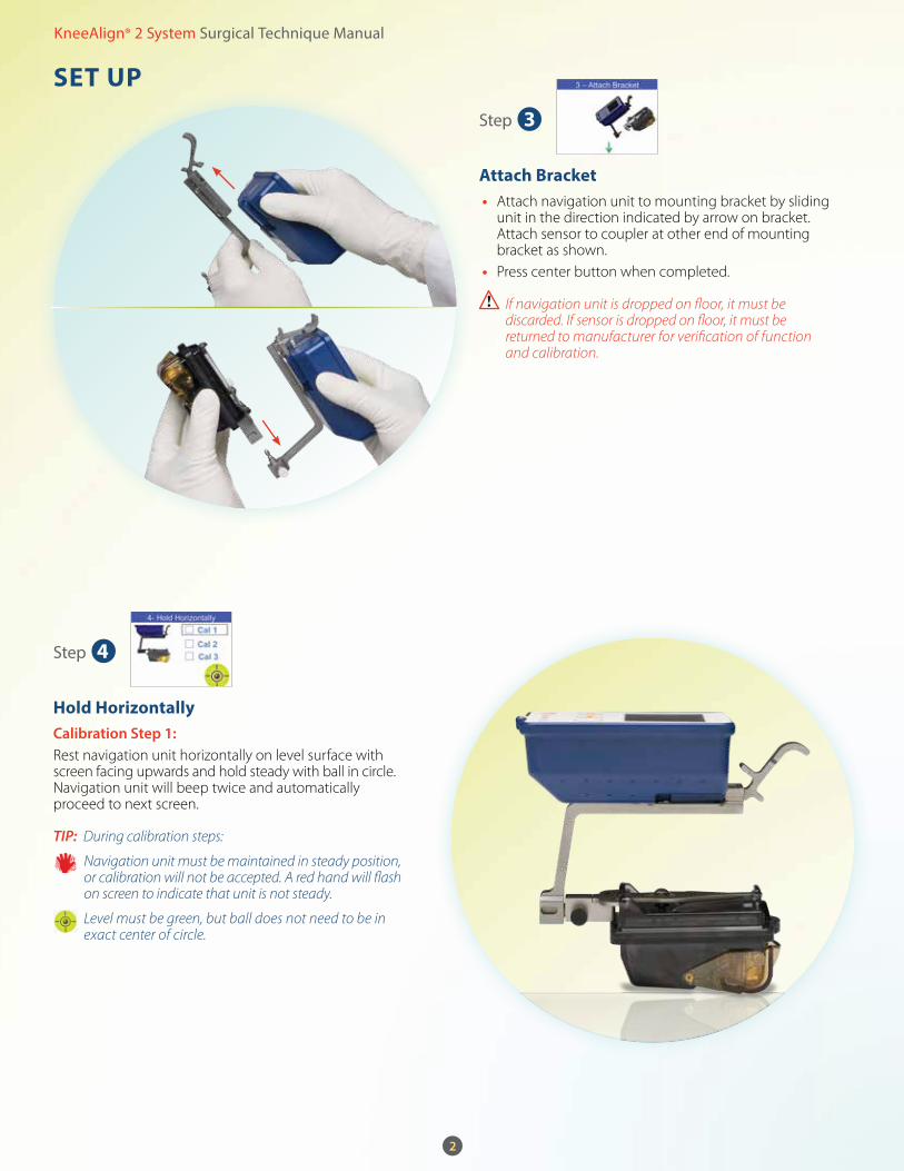
Attach Bracket • Attach navigation unit to mounting bracket by sliding
unit in the direction indicated by arrow on bracket. Attach sensor to coupler at other end of mounting bracket as shown.
• Press center button when completed.
If navigation unit is dropped on floor, it must be discarded. If sensor is dropped on floor, it must be returned to manufacturer for verification of function and calibration.
Hold Horizontallycalibration Step 1: Rest navigation unit horizontally on level surface with screen facing upwards and hold steady with ball in circle. Navigation unit will beep twice and automatically proceed to next screen.
TIP: During calibration steps:
Navigation unit must be maintained in steady position, or calibration will not be accepted. A red hand will flash on screen to indicate that unit is not steady.
Level must be green, but ball does not need to be in exact center of circle.
Step
Step
3
4

3
KneeAlign® 2 System Surgical Technique Manual
SeT up
Hold Verticallycalibration Step 2: Rest navigation unit vertically on level surface and hold steady with ball in circle. Navigation unit will beep twice and automatically proceed to next screen.
Verify Calibrationcalibration Step 3: Rest navigation unit in angled position on level surface and hold steady with ball in circle. Navigation unit will beep twice and automatically proceed to next screen.
TIP: Displayed angles should be 2° or less.
If navigation unit does not proceed to the next screen after several seconds, check that navigation unit and sensor are correctly attached to the bracket and press left button twice to repeat from step 4.
Step
Step
5
6
KneeAlign® 2 System Surgical Technique Manual
4
SeT up
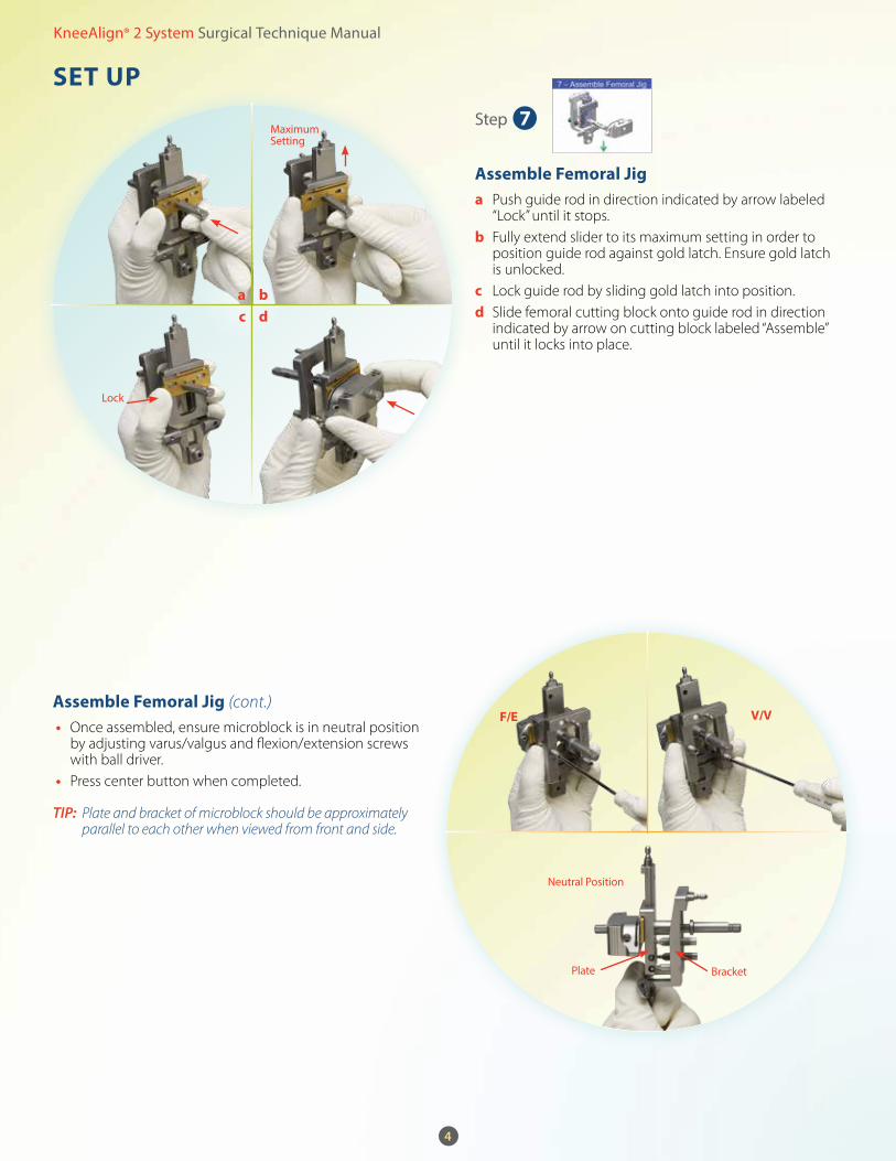
Assemble Femoral Jig (cont.)
• Once assembled, ensure microblock is in neutral position by adjusting varus/valgus and flexion/extension screws with ball driver.
• Press center button when completed.
TIP: Plate and bracket of microblock should be approximately parallel to each other when viewed from front and side.
Step 7
Assemble Femoral Jiga Push guide rod in direction indicated by arrow labeled
“Lock” until it stops.b Fully extend slider to its maximum setting in order to
position guide rod against gold latch. Ensure gold latch is unlocked.
c Lock guide rod by sliding gold latch into position.d Slide femoral cutting block onto guide rod in direction
indicated by arrow on cutting block labeled “Assemble” until it locks into place.
Lock
Maximum Setting
Neutral Position
F/e V/V
Plate Bracket
adcb

KneeAlign® 2 System Surgical Technique Manual
SeT up
Assemble Tibial Jig • Assemble tibial jig as follows: • Set fixation arm on proximal end of tibial jig to “Left”
or “Right” for leg being operated on. • Ensure that varus/valgus and posterior slope levers
of tibial jig are locked. • Attach midline probe (a) to proximal end of tibial jig. • Attach shin spacer (b) to tibial jig. • Attach ankle tube (c) to distal end of tibial jig and lock
in place. • Attach malleolar probe (d) to ankle tube. • Press center button on navigation unit when completed.
TIP: Fixation arm is spring-loaded and may be adjusted by pulling arm away from jig, then rotating.
TIP: Shin spacer may already be attached.
TIP: Squeeze button on ankle tube and insert malleolar probe through slot until it reaches limit of its travel.
Use curved malleolar probe to extend range for extremely long or short tibias.
Step 8
5
Assembled Tibial JigTibial Jig Assembly Order
b
a
d
c

Step 10
KneeAlign® 2 System Surgical Technique Manual
6
SeT up
Select Knee • Press button to select “L” (Left) or “R” (Right) for leg
being operated on.
Select Bone • Press button to select tibia or femur.
TIP: If “TIB” is selected, proceed to Tibia resection steps on page 12.
If “FEM” is selected, proceed to Femur resection steps on page 7.
Step 9

7
KneeAlign® 2 System Surgical Technique Manual
Femur
Secure on Femur • Expose knee. • Place knee in flexion and seat microblock on femur
in approximately neutral varus/valgus and flexion/extension position.
• Insert headed pin in center hole of microblock slider and drive it into most distal point of sulcus of trochlea, directing it toward center of femoral head.
TIP: A typical IM drill placement approximates this point. Do not bias medially or laterally.
• Rotate microblock to approximately line up with Whiteside’s line.
• Slide microblock in anterior/posterior direction as necessary to achieve three-point contact to femur. Pin medial and lateral feet of instrument against condyles, using headed pins provided in instrument tray.
• Press center button when completed.
Hardened, stainless steel headed pins provided in instrument tray should be used.
Do not impact or hammer system components.
TIP: Verify that there is approximately 10 mm of clearance between femoral cutting block and anterior condyles.
Input A/p Offset • Read anterior/posterior offset position of center pin
on microblock slider scale. • Enter offset value into navigation unit by pressing
right button until correct number is displayed on bottom right corner of screen.
• Press center button when completed.
TIP: If displayed value exceeds desired offset, continue to press right button to cycle back to desired value.
Step
Step
1
2
Whiteside’s Line
Epicondylar Axis
Read A/P Offset

maneuver Leg
KneeAlign® 2 System Surgical Technique Manual
8
Femur
Attach Sensors • Attach navigation unit and sensor to microblock.
Align ball in center of rectangular box on side of screen by changing angle of femur until box turns green.
TIP: Navigation unit on mounting bracket should be attached to coupler adjacent to white dot on microblock. Sensor should be attached to coupler adjacent to black dot on microblock.
TIP: If sensor is not attached correctly, box on the side of screen will not appear and screen will read “Mount Sensor Here.”
Once navigation unit and sensor are attached, do not adjust varus/valgus or flexion/extension screws of microblock until after completing hip point registration (Femur–Step 4).
Step
Step
3
4hold Still in Start Position Move Knee Medial/lateral

9
KneeAlign® 2 System Surgical Technique Manual
Femur
TIPs for Maneuver: Maneuver must be completed before beeping stops
and as rapidly as possible.
TIP: Maneuver leg using two hands, grasping behind knee and ankle. Do not hold navigation unit or femoral jig.
Rotate knee between 10° and 45° subtended during registration maneuver.
For accurate results, it is important that hip is kept stationary during registration. Knee must be returned to start position (within ± 2 cm and ± 5° rotation).
TIP: Following maneuver completion, during hip point calculation, navigation unit screen will provide user with feedback on speed of maneuver in medial-lateral (M/L) and anterior-posterior (A/P) planes. Green bars displayed for a given plane indicate that speed of the maneuver is sufficient in that plane. Red bars displayed for a given plane indicate that speed in that plane is insufficient.
TIP: In the event maneuver is too slow in a given plane, or otherwise insufficient, navigation unit screen will provide instructions to repeat maneuver.
maneuver Leg • Hold femur stationary until green light appears
on navigation unit screen and unit starts to beep continuously. As soon as navigation unit starts beeping, maneuver femur rapidly as follows while keeping the pelvis stationary:
• First, move knee in medial-lateral arc by internally and/or externally rotating hip while keeping heel on table, and maintaining knee in flexion.
• Next, move knee in sagittal plane by flexing and extending hip.
Flex/Extend hip Return gently to Start Position, hold Still
Step 4

KneeAlign® 2 System Surgical Technique Manual
10
Femur
Set resection plane • Set desired varus/valgus and flexion/extension angles
using ball driver to adjust microblock’s navigation screws. • Press center button when completed.
TIP: Navigation unit must be oriented within its operating range in order for unit to display resection angles.
TIP: Varus/valgus and flexion/extension angles are measured relative to mechanical axis of femur.
Do not attempt to adjust cutting block orientation by applying force to jig. Angles must be adjusted using ball driver to adjust screws prior to pinning the cutting block.
Applying excessive torque to adjustment screws at limit of travel will cause damage to microblock.
If bone interferes with cutting block while setting resection angle, microblock has been pinned in too much flexion. Two alternatives may be considered:1. Use sagittal saw to trim interfering bone to provide
additional travel for cutting block. Care should be taken not to remove too much bone, which could cause notching or interfere with subsequent sizing.
2. Unpin microblock and re-pin closer to neutral flexion angle, repeating Femur–Steps 1-4.
Set resection Depth • Remove navigation unit/bracket assembly, and sensor
from microblock. a Attach distal guide to microblock guide rod by
squeezing pushbutton (b), and slide distal guide to desired resection depth (c).
d Press gold latch on side of microblock to unlock guide rod/cutting block assembly from its maximum anterior position. Position distal guide paddles flush against condyles, and slide cutting block posteriorly to contact femur.
e Pin distal femoral cutting block to anterior femur using most proximal holes using headless pins provided in instrument tray.
f Remove pins from microblock by pulling in distal direction, while securely holding cutting block in place. Fix cutting block with oblique pin if desired.
g Resect distal femur. • Press center button when completed.
Step 5
F/eV/V
Resection Scale
Unlock
adcb
Step 6
11
KneeAlign® 2 System Surgical Technique Manual
Femur
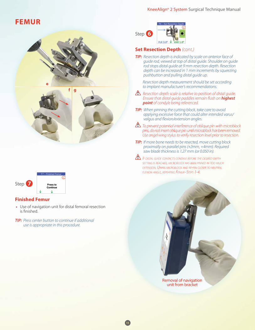
Set resection Depth (cont.)
TIP: Resection depth is indicated by scale on anterior face of guide rod, viewed at top of distal guide. Shoulder on guide rod stops distal guide at 9 mm resection depth. Resection depth can be increased in 1 mm increments by squeezing pushbutton and pulling distal guide up.
Resection depth measurement should be set according to implant manufacturer’s recommendations.
Resection depth scale is relative to position of distal guide. Ensure that distal guide paddles remain flush on highest point of condyle being referenced.
TIP: When pinning the cutting block, take care to avoid applying excessive force that could alter intended varus/valgus and flexion/extension angles.
To prevent potential interference of oblique pin with microblock pins, do not insert oblique pin until microblock has been removed. Use angel wing stylus to verify resection level prior to resection.
TIP: If more bone needs to be resected, move cutting block proximally on parallel pins (+2mm, +4mm). Required saw blade thickness is 1.27 mm (or 0.050 in).
If dIstal guIde contacts condyle before the desIred depth settIng Is reached, mIcroblock has been pInned In too much extensIon. unpIn mIcroblock and re-pIn closer to neutral flexIon angle, repeatIng femur–steps 1-4.
Finished Femur • Use of navigation unit for distal femoral resection
is finished.
TIP: Press center button to continue if additional use is appropriate in this procedure.
Step 6
Removal of navigation unit from bracket
egf
Step 7

KneeAlign® 2 System Surgical Technique Manual
12
TIBIA
Attach Sensors • Remove navigation unit and sensor from
mounting bracket and attach to tibial jig. • Press center button when completed.
TIP: Attach sensor so that it is on lateral side of tibial jig (opposite fixation arm) during procedure.
Secure on Tibiaa Pull malleolar probe to maximum anterior position in
order to avoid interference during placement of jig.b Place tibial jig on anterior tibia, aligning etched line on
fixation arm of jig with medial third of tibial tubercle.c Position tip of midline probe just posterior to insertion
of Anterior Cruciate Ligament (ACL).d Secure fixation arm to tibia with at least two headed
pins provided in instrument tray.e Secure mid-tibia v-rest of tibial jig with calf strap. • Press center button when completed.
Step
Step
1
2
a
d
c b
13
KneeAlign® 2 System Surgical Technique Manual
TIBIA
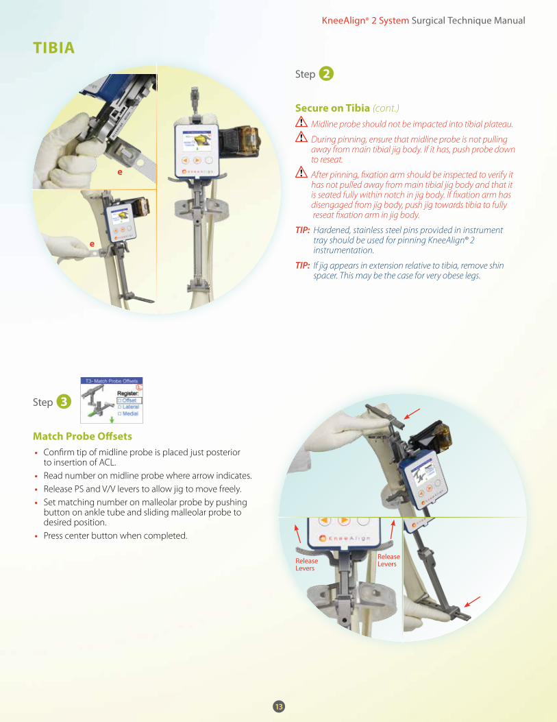
Secure on Tibia (cont.)
Midline probe should not be impacted into tibial plateau.
During pinning, ensure that midline probe is not pulling away from main tibial jig body. If it has, push probe down to reseat.
After pinning, fixation arm should be inspected to verify it has not pulled away from main tibial jig body and that it is seated fully within notch in jig body. If fixation arm has disengaged from jig body, push jig towards tibia to fully reseat fixation arm in jig body.
TIP: Hardened, stainless steel pins provided in instrument tray should be used for pinning KneeAlign® 2 instrumentation.
TIP: If jig appears in extension relative to tibia, remove shin spacer. This may be the case for very obese legs.
match probe Offsets • Confirm tip of midline probe is placed just posterior
to insertion of ACL. • Read number on midline probe where arrow indicates. • Release PS and V/V levers to allow jig to move freely. • Set matching number on malleolar probe by pushing
button on ankle tube and sliding malleolar probe to desired position.
• Press center button when completed.
Step
Step
2
3
e
e
Release Levers
Release Levers

KneeAlign® 2 System Surgical Technique Manual
14
TIBIA
register Lateral malleolus • Palpate lateral malleolus and place cup of malleolar
probe on its apex. • Press center button to register lateral malleolus.
TIP: Extend jig distally if necessary, by releasing ankle tube latch.
In event that leg is positioned at orientation outside of range of KneeAlign® 2 system, box at top center of screen will turn orange. Change position of leg until black ball is within square box and box has turned green.
TIP: A double beep will sound on registration.
Navigation unit must be maintained in steady position or red hand will flash on screen.
Ankle tube should be locked during registration.
register medial malleolus • Palpate medial malleolus and place cup of malleolar
probe on its apex. Press center button on navigation unit to register medial malleolus.
TIP: A double beep will sound upon registration.
After registration, do not move base of jig relative to tibia. Keep fixation arm and v-rest in their attached positions. Pushing or pulling fixed base of jig may introduce errors in navigation accuracy.
Step
Step
4
5

15
KneeAlign® 2 System Surgical Technique Manual
TIBIA
Set resection plane • Retract malleolar probe to maximum anterior position. • Move distal end of tibial jig to obtain desired varus/
valgus and posterior slope angles and lock in place with side levers.
TIP: Malleolar probe may be adjusted to assist in setting posterior slope angle.
Do not use malleolar probe to set posterior slope angle if posterior slope lever is locked.
After locking levers, do not move jig relative to the tibia. Pushing or pulling locked bars of the jig may introduce errors in navigation accuracy.
KneeAlign® 2 System does not display measurement values when oriented outside of its operating range. Change position of leg until black ball is within rectangular box and box has turned green.
• Press center button on KneeAlign® 2 when this step is completed and remove midline probe by pulling straight up.
Step 6
V/V
Posterior Slope
P/S LockV/V
Lock
KneeAlign® 2 System Surgical Technique Manual
16
TIBIA
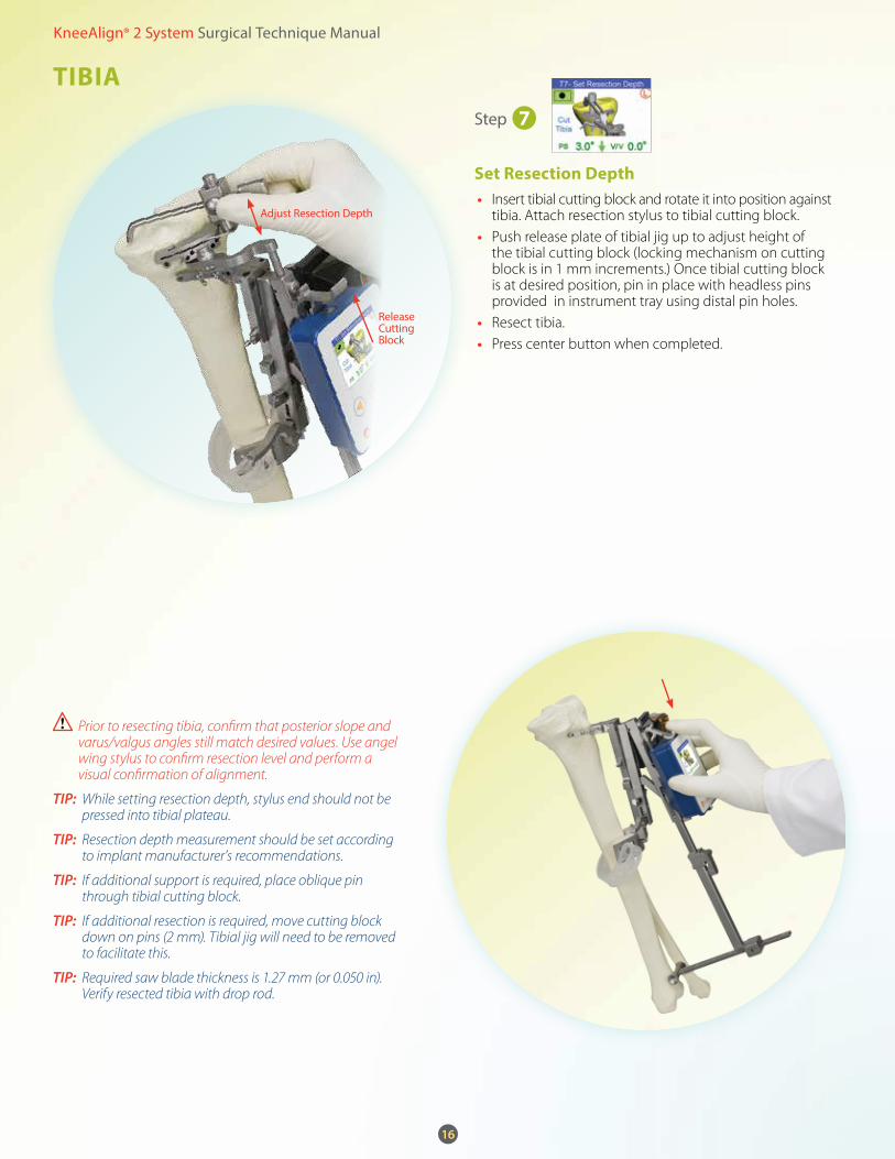
Set resection Depth • Insert tibial cutting block and rotate it into position against
tibia. Attach resection stylus to tibial cutting block. • Push release plate of tibial jig up to adjust height of
the tibial cutting block (locking mechanism on cutting block is in 1 mm increments.) Once tibial cutting block is at desired position, pin in place with headless pins provided in instrument tray using distal pin holes.
• Resect tibia. • Press center button when completed.
Prior to resecting tibia, confirm that posterior slope and varus/valgus angles still match desired values. Use angel wing stylus to confirm resection level and perform a visual confirmation of alignment.
TIP: While setting resection depth, stylus end should not be pressed into tibial plateau.
TIP: Resection depth measurement should be set according to implant manufacturer’s recommendations.
TIP: If additional support is required, place oblique pin through tibial cutting block.
TIP: If additional resection is required, move cutting block down on pins (2 mm). Tibial jig will need to be removed to facilitate this.
TIP: Required saw blade thickness is 1.27 mm (or 0.050 in). Verify resected tibia with drop rod.
Step 7
Release Cutting Block
Adjust Resection Depth

KneeAlign® 2 System Surgical Technique Manual
TIBIA
DISpOSAL
Finished Tibia • Use of navigation unit for tibial resection is finished.
TIP: Press the center button to continue if additional use is appropriate in this procedure.
Prior to disposal, power off navigation unit by pressing left and right buttons for 2 seconds.
a To power off navigation unit, press and hold down left and right buttons simultaneously.
• Navigation unit must be powered off and discarded.b Battery must be removed from sensor and discarded • Sensor, calf strap, and pins must NOT be discarded.
These items should be returned to their designated locations in the instrument tray.
Step 8
17
a b
KneeAlign® 2 System Surgical Technique Manual
18
TrOuBLeSHOOTIng
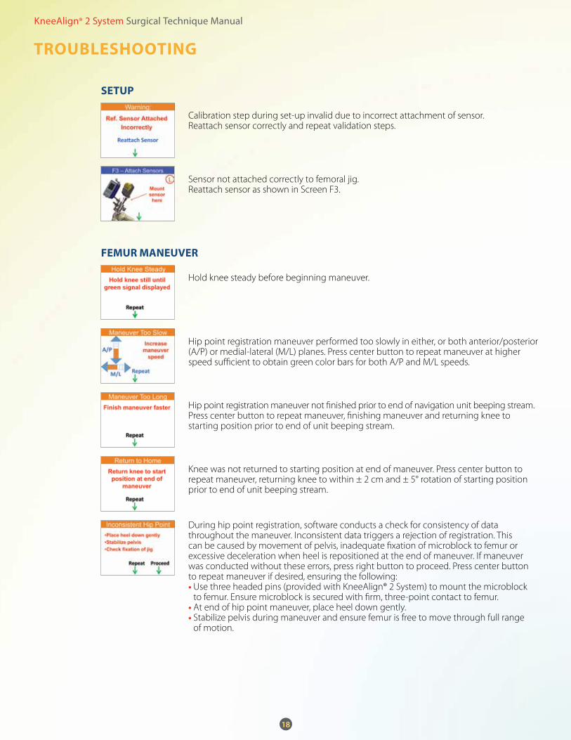
Sensor not attached correctly to femoral jig. Reattach sensor as shown in Screen F3.
Calibration step during set-up invalid due to incorrect attachment of sensor. Reattach sensor correctly and repeat validation steps.
Hold knee steady before beginning maneuver.
Hip point registration maneuver performed too slowly in either, or both anterior/posterior (A/P) or medial-lateral (M/L) planes. Press center button to repeat maneuver at higher speed sufficient to obtain green color bars for both A/P and M/L speeds.
Hip point registration maneuver not finished prior to end of navigation unit beeping stream. Press center button to repeat maneuver, finishing maneuver and returning knee to starting position prior to end of unit beeping stream.
Knee was not returned to starting position at end of maneuver. Press center button to repeat maneuver, returning knee to within ± 2 cm and ± 5° rotation of starting position prior to end of unit beeping stream.
During hip point registration, software conducts a check for consistency of data throughout the maneuver. Inconsistent data triggers a rejection of registration. This can be caused by movement of pelvis, inadequate fixation of microblock to femur or excessive deceleration when heel is repositioned at the end of maneuver. If maneuver was conducted without these errors, press right button to proceed. Press center button to repeat maneuver if desired, ensuring the following:• Use three headed pins (provided with KneeAlign® 2 System) to mount the microblock
to femur. Ensure microblock is secured with firm, three-point contact to femur.• At end of hip point maneuver, place heel down gently.• Stabilize pelvis during maneuver and ensure femur is free to move through full range
of motion.
SeTup
Femur mAneuVer

KneeAlign® 2 System Surgical Technique Manual
19
TrOuBLeSHOOTIng
Generic hip point failure. Press center button to repeat maneuver.
No maneuver detected. Press center button to repeat.
Press center button to repeat maneuver, increasing femoral rotation to at least 10°.
Jig pinned out of range of valid varus/valgus and/or flexion/extension values. Adjust or re-pin jig into neutral position and press center button to repeat maneuver.If jig re-pinned, back up to Femur Step 1.
Sensor medial-lateral position on tibial jig was changed during registration process. Attach sensor to lateral side of tibial jig and restart tibial navigation Step 3 (Register Lateral Malleolus).
There is a major system fault and navigation unit must be turned off and replaced. Please recover faulty unit and return to manufacturer for analysis.
Sensor signal is lost. Remove and reattach sensor battery to re-establish connection.
Femur mAneuVer (cont.)
TIBIA
SySTem

KneeAlign® 2 System Surgical Technique Manual
20
TeCHnICAL BuLLeTIn
DescriptionAppropriate placement and fixation of the femoral jig is necessary for system function. Placing the jig either in too much flexion or in too much extension can result in subsequent interference between the instruments and the femur.
Instructions • Prior to pinning the microblock, adjust it to be in a neutral position
as shown in set-up step 7 of the technique. • When pinning the microblock, orient the middle pin so that it is pointing
toward the head of the femur. • Prior to inserting the medial and lateral fixation pins, ensure A/P offset scale
is at least 3, unless the A/P size of the distal femur is exceptionally small. • Verify that there is approximately 10mm clearance between the femoral
cutting block and the anterior aspect of the femur (Figure 1). • If the femur interferes with the cutting block while setting the resection
angle (Figure 2), a sagittal saw may be used to trim the interfering bone to provide additional travel for the cutting block. Care should be taken not to remove too much bone, which could cause notching or interfere with subsequent sizing.– Alternatively, the microblock may be re-pinned in a more favorable position. In this case registration and
resection angle adjustment steps must be repeated. • If the distal guide contacts the condyles or other instrumentation before reaching the desired resection depth
(Figure 3), the guide may be set at a depth 2 mm or 4 mm greater than the target depth. Pin the cutting block using the +2 mm or +4 mm holes, and shift the cutting block distally after removing the Microblock.– Alternatively, the microblock may be re-pinned in a more favorable position. In this case registration and
resection angle adjustment steps must be repeated.
1. pLACemenT OF FemOrAL JIg
Clearance
Microblock Angle
Microblock Angle
Cutting block interfers with femur when adjusted toward neutral flexion.
Distal guide contacts condyles before desired depth is reached
Pin Axis
Pin Axis
Mechanical Axis
Mechanical Axis
figure 1. Neutral placement of the microblock. Note clearance between the femur and the cutting block.
figure 2. Mounting the microblock in excessive flexion results in interference between the cutting block and femur.
figure 3. Mounting the microblock in excessive extension results in interference between the distal guide and femoral condyles before reaching desired resection depth.
KneeAlign® 2 System Surgical Technique Manual
21
TeCHnICAL BuLLeTIn
DescriptionDuring hip point registration the software requires that the user maintain a minimum average angular speed in both the A/P and M/L directions. If either speed falls below the allowed limit the registration will be rejected. The display on the navigation unit will indicate the maneuver speeds for each direction (A/P and M/L). More bars indicate higher speed. Green bars indicate sufficient maneuver speed, while red bars indicate insufficient speed.
Instructions • Prior to surgery, practice maneuver on sawbones to develop a feel for a suitable maneuver speed. • If a “Maneuver Too Slow” message is received, increase the speed of the maneuver in the direction
indicated by red bars on the navigation unit display. • A common tendency is to exaggerate the A/P motion when increasing maneuver speed. If only
the M/L direction needs to be accelerated, do not unnecessarily exaggerate the A/P motion. • Take care not to move the pelvis by exaggerating the size of the maneuver when increasing
maneuver speed.
DescriptionDuring hip point registration, the software conducts a check for consistency of the data throughout the maneuver. Inconsistent data triggers a rejection of the registration. This can be caused by movement of the pelvis, inadequate fixation of the microblock to the femur or excessive deceleration when the heel is repositioned at the end of the maneuver.
Instructions • Use at least three headed pins to mount the Microblock to the femur. Ensure the Microblock is
secured with firm, three-point contact to the femur.
• At the end of the hip point maneuver, place the heel down gently.
• Stabilize the pelvis during the maneuver and ensure that the femur is free to move through the full range of motion.
• Remove any retractors or other instruments that could hit the sensor during the hip point maneuver.
2. “mAneuVer TOO SLOw” reJeCTIOn DurIng HIp pOInT regISTrATIOn
3. “InCOnSISTenT HIp pOInT” errOr DurIng HIp pOInT regISTrATIOn
KneeAlign® 2 System Surgical Technique Manual
22
TeCHnICAL BuLLeTIn
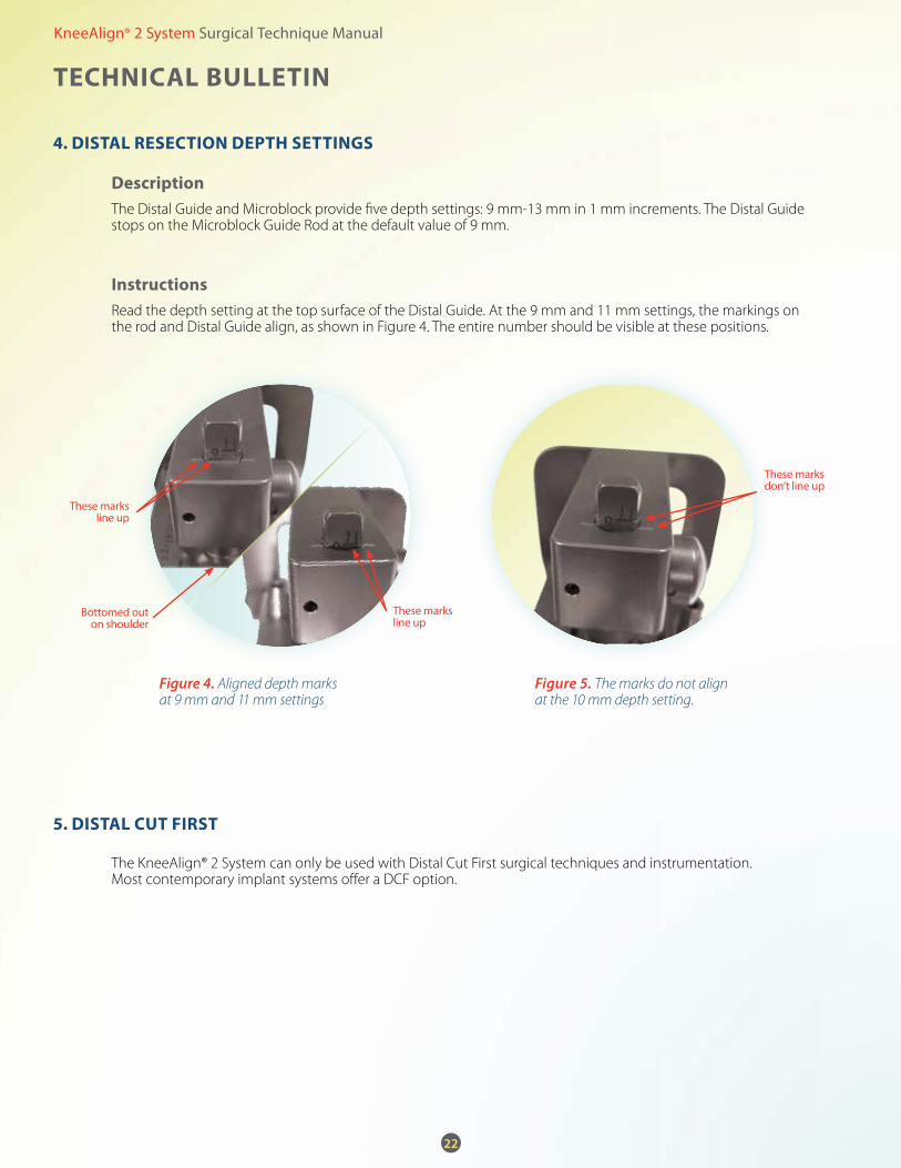
DescriptionThe Distal Guide and Microblock provide five depth settings: 9 mm-13 mm in 1 mm increments. The Distal Guide stops on the Microblock Guide Rod at the default value of 9 mm.
InstructionsRead the depth setting at the top surface of the Distal Guide. At the 9 mm and 11 mm settings, the markings on the rod and Distal Guide align, as shown in Figure 4. The entire number should be visible at these positions.
The KneeAlign® 2 System can only be used with Distal Cut First surgical techniques and instrumentation. Most contemporary implant systems offer a DCF option.
4. DISTAL reSeCTIOn DepTH SeTTIngS
5. DISTAL CuT FIrST
figure 4. Aligned depth marks at 9 mm and 11 mm settings
figure 5. The marks do not align at the 10 mm depth setting.
These marks line up
These marks line up
These marks don’t line up
Bottomed out on shoulder
KneeAlign® 2 System Surgical Technique Manual
23
InSTrumenT SpeCIFICATIOnS
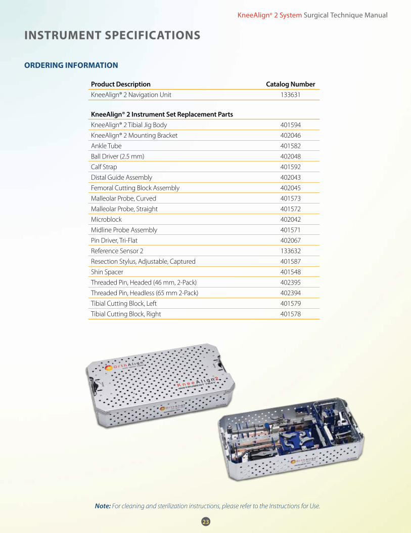
OrDerIng InFOrmATIOn
note: For cleaning and sterilization instructions, please refer to the Instructions for Use.
Product description catalog numberKneeAlign® 2 Navigation Unit 133631
KneeAlign® 2 instrument Set Replacement PartsKneeAlign® 2 Tibial Jig Body 401594
KneeAlign® 2 Mounting Bracket 402046
Ankle Tube 401582
Ball Driver (2.5 mm) 402048
Calf Strap 401592
Distal Guide Assembly 402043
Femoral Cutting Block Assembly 402045
Malleolar Probe, Curved 401573
Malleolar Probe, Straight 401572
Microblock 402042
Midline Probe Assembly 401571
Pin Driver, Tri-Flat 402067
Reference Sensor 2 133632
Resection Stylus, Adjustable, Captured 401587
Shin Spacer 401548
Threaded Pin, Headed (46 mm, 2-Pack) 402395
Threaded Pin, Headless (65 mm 2-Pack) 402394
Tibial Cutting Block, Left 401579
Tibial Cutting Block, Right 401578

KneeAlign® 2 System Surgical Technique Manual
24
Curv
ed M
alle
olar
Pr
obe
Tibi
al C
uttin
g Bl
ocks
(le
ft an
d rig
ht)
Sens
or
Ankl
e
Tube
Calf
St
rap
Stra
ight
M
alle
olar
Pr
obe
Shin
Sp
acer
Thre
aded
Pin
H
eade
d
(46
mm
)Kn
eeAl
ign®
2
Tibi
al Ji
g Bo
dyPi
n
Driv
er
Adju
stab
le
Styl
usBa
ll
Driv
erD
istal
G
uide
Mic
robl
ock
Mid
line
Prob
e
Mou
ntin
g
Brac
ket
Dist
al
Fem
oral
Cu
ttin
g Bl
ock
Thre
aded
Pin
H
eadl
ess
(65
mm
)

KneeAlign® 2 System Surgical Technique Manual
nOTeS

11/2013 001029 Rev P
120 Columbia, Suite 500Aliso Viejo, CA 92656866.582.0879
www.orthalign.com
OrthAlign is committed to providing surgeons with user-friendly, cost-effective, surgical navigation products for precise alignment.
For more information about the KneeAlign® 2 System, please contact us at 866.582.0879 or [email protected].
About OrthAlign, Inc.