kmt sl-v pump manual
TRANSCRIPT
MANUAL 20413039(R05)
STREAMLINE SL-V 50 PLUSWATERJET INTENSIFIER
OPERATION AND MAINTENANCE MANUAL

20412906 1-2006/Rev 04
NOTICE
This document contains subject matter in which KMT Waterjet Systems has proprietary rights. Recipients of this document shall not duplicate, use or disclose information contained herein, in whole or in part, for other than the purpose for which this manual was provided.
KMT Waterjet believes the information described in this manual to be accurate and reliable. Much care has been taken in its preparation; however, the Company cannot accept any responsibility, financial or otherwise, for any consequences arising out of the use of this material. The information contained herein is subject to change, and revisions may be issued advising of such changes and/or additions.
KMT WATERJET SYSTEMS 2004
KMT Waterjet Systems 635 West 12th Street POB 231 Baxter Springs, KS 66713-0231
Phone: Fax:
(800) 826-9274 (620) 856-5050

20412906 1-2006/Rev 04 i
TABLE OF CONTENTS
Title Page Notice Table of Contents Appendix
Section Page
1 Introduction....................................................................................................... 1-1 1.1 Overview................................................................................................ 1-1 1.2 Performance Features and Options ........................................................ 1-1 1.3 Operational Overview............................................................................ 1-3
Low Pressure Water System .................................................................. 1-3 Recirculation System ............................................................................. 1-3 Hydraulic System................................................................................... 1-3 High Pressure Water System ................................................................. 1-4 Operating System................................................................................... 1-4
1.4 Safety ..................................................................................................... 1-5 Lockout/Tagout Procedure..................................................................... 1-5 Warning Labels...................................................................................... 1-6 Emergency Medical Treatment.............................................................. 1-8
1.5 Worldwide Product Support .................................................................. 1-9 1.6 Spare Parts ............................................................................................. 1-9 1.7 Manual Organization ............................................................................. 1-9 1.8 Equipment and Service Manual Questionnaire...................................... 1-10
2 Installation ......................................................................................................... 2-1 2.1 Overview................................................................................................ 2-1 2.2 Installation Summary ............................................................................. 2-1 2.3 Site Requirements .................................................................................. 2-2
Transporting........................................................................................... 2-3 2.4 Power Requirements .............................................................................. 2-4 2.5 Service Connections............................................................................... 2-6
Cooling Water........................................................................................ 2-7 Cutting Water......................................................................................... 2-7 Drain ...................................................................................................... 2-8 Plant Air ................................................................................................. 2-8
2.6 Flow Requirements ................................................................................ 2-8 2.7 High Pressure Piping.............................................................................. 2-9
Measurements and Dimensions ............................................................. 2-10 Hand Coning .......................................................................................... 2-11

20412906 1-2006/Rev 04 ii
Power Coning......................................................................................... 2-12 Hand Threading ..................................................................................... 2-13 Power Threading.................................................................................... 2-14
2.8 High Pressure Connections .................................................................... 2-14 Standard Connections ............................................................................ 2-15 Anti-Vibration Connections................................................................... 2-16
2.9 Commissioning ...................................................................................... 2-17 2.10 Decommissioning .................................................................................. 2-20
3 Maintenance ...................................................................................................... 3-1 3.1 Overview................................................................................................ 3-1 3.2 Maintenance........................................................................................... 3-1
Daily Inspection ..................................................................................... 3-1 Periodic Maintenance............................................................................. 3-1 High Pressure System Maintenance....................................................... 3-2
3.3 Maintenance Precautions ....................................................................... 3-3
4 Operation ........................................................................................................... 4-1 4.1 Overview................................................................................................ 4-1 4.2 Startup Sequence.................................................................................... 4-2
Startup after Motor Stop ........................................................................ 4-2 Startup after Emergency Stop ................................................................ 4-2
4.3 Display Controls .................................................................................... 4-3 4.4 Main Menu............................................................................................. 4-4 4.5 Run Screens ........................................................................................... 4-5 4.6 Pressure Control Screen......................................................................... 4-6 4.7 Setup Screens ......................................................................................... 4-7 4.8 Stroke Rate Screen................................................................................. 4-9 4.9 Hours Screen.......................................................................................... 4-11 4.10 Run Screen Alarms ................................................................................ 4-12 4.11 Alarm Banners ....................................................................................... 4-14 4.12 Alarms Screen........................................................................................ 4-16
Installing a New Battery ........................................................................ 4-17 4.13 Alarm History ........................................................................................ 4-18
Changing the Date and Time ................................................................. 4-18 4.14 Configuration Screen ............................................................................. 4-19 4.15 Maintenance Screen ............................................................................... 4-19 4.16 Language Screen.................................................................................... 4-20
5 Low Pressure Water System ............................................................................ 5-1 5.1 Overview................................................................................................ 5-1 5.2 Cutting Water Supply ............................................................................ 5-2 5.3 Operation................................................................................................ 5-2 5.4 Operating Specifications........................................................................ 5-4 5.5 Service and Maintenance Procedures .................................................... 5-5
Filter Assembly and Strainer Maintenance............................................ 5-5
20412906 1-2006/Rev 04 iii
Booster Pump Adjustment ..................................................................... 5-6 5.6 Troubleshooting ..................................................................................... 5-8
6 Recirculation System ........................................................................................ 6-1 6.1 Overview................................................................................................ 6-1 6.2 Operation................................................................................................ 6-2 6.3 Operating Specifications........................................................................ 6-4 6.4 Service and Maintenance Procedures .................................................... 6-4
Hydraulic Oil Maintenance.................................................................... 6-5 Oil Filter Maintenance ........................................................................... 6-7 Operating Temperature Adjustment ...................................................... 6-8
6.5 Troubleshooting ..................................................................................... 6-10
7 Hydraulic System .............................................................................................. 7-1 7.1 Overview................................................................................................ 7-1 7.2 Optional System Components................................................................ 7-2 7.3 Operation................................................................................................ 7-2 7.4 Operating Specifications........................................................................ 7-4 7.5 Service and Maintenance Procedures .................................................... 7-4
Hydraulic Operating Pressure ................................................................ 7-4 Proportional Valve Maintenance ........................................................... 7-7 Motor Maintenance................................................................................ 7-8 Flexible Coupling Replacement............................................................. 7-8 Hydraulic Compensator Maintenance.................................................... 7-10 Hydraulic Pump or Electric Motor Replacement................................... 7-13 Hydraulic Oil Replacement.................................................................... 7-18
7.6 Troubleshooting ..................................................................................... 7-20
8 Electrical System ............................................................................................... 8-1 8.1 Overview................................................................................................ 8-1 8.2 Optional System Components................................................................ 8-1 8.3 Operation................................................................................................ 8-2
Sensors and Solenoids............................................................................ 8-5 Softstarter............................................................................................... 8-10
8.4 Service and Maintenance Procedures .................................................... 8-11 Proximity Switch Maintenance.............................................................. 8-11 Optical Relay Maintenance.................................................................... 8-12
8.5 Troubleshooting ..................................................................................... 8-14
9 High Pressure Water System ........................................................................... 9-1
9.1 Overview................................................................................................ 9-1 9.2 System Options ...................................................................................... 9-2 9.3 Operation................................................................................................ 9-2
Redundant Intensifiers ........................................................................... 9-4 Dual Intensifiers..................................................................................... 9-5
9.4 Operating Specifications........................................................................ 9-6
20412906 1-2006/Rev 04 iv
9.5 System Components............................................................................... 9-7 9.6 Service and Maintenance Overview ...................................................... 9-8
Torque Specifications ............................................................................ 9-9 Specialized Maintenance Tools ............................................................. 9-11
9.7 High and Low Pressure Water Piping.................................................... 9-12 9.8 High Pressure Cylinder Assembly ......................................................... 9-12
High Pressure Cylinder Assembly Removal.......................................... 9-13 High Pressure Cylinder Assembly Installation ...................................... 9-14 High Pressure Cylinder Maintenance .................................................... 9-15
9.9 Hard Seal End Caps ............................................................................... 9-16 Hard Seal End Cap Removal ................................................................. 9-16 Hard Seal End Cap Installation.............................................................. 9-17
9.10 Sealing Head .......................................................................................... 9-18 High Pressure Discharge Check Valve .................................................. 9-19 Low Pressure Inlet Check Valve............................................................ 9-21 Sealing Head Maintenance .................................................................... 9-22
9.11 High Pressure Seal Assembly ................................................................ 9-23 9.12 Hydraulic Cartridge Seal and Plunger Removal.................................... 9-25
Plunger Maintenance ............................................................................. 9-28 Plunger Installation ................................................................................ 9-28 Hydraulic Cartridge Seal........................................................................ 9-28
9.13 Hydraulic Piston..................................................................................... 9-31 Hydraulic Piston Removal ..................................................................... 9-31 Bearing Rings and Seal Assembly......................................................... 9-33 Plunger Button Sockets, Seals and Retainer Pins .................................. 9-34 Internal Check Valves............................................................................ 9-34 Hydraulic Piston Installation.................................................................. 9-35
9.14 Hydraulic Cylinder Maintenance........................................................... 9-36 9.15 High Pressure Attenuator....................................................................... 9-36 9.16 High Pressure Dump Valve ................................................................... 9-37
Pneumatic Control Valve....................................................................... 9-38 Pneumatic Actuator................................................................................ 9-42
9.17 Weep Holes............................................................................................ 9-43 9.18 Troubleshooting ..................................................................................... 9-46
10 Troubleshooting ................................................................................................ 10-1 10.1 Overview................................................................................................ 10-1 10.2 Troubleshooting Guide .......................................................................... 10-2
11 Specifications ..................................................................................................... 11-1 11.1 Overview................................................................................................ 11-1 11.2 Installation Specifications...................................................................... 11-1
Environment........................................................................................... 11-1 Sound Level ........................................................................................... 11-2 Equipment Dimensions and Weights..................................................... 11-2 Service Connections............................................................................... 11-2
20412906 1-2006/Rev 04 v
11.3 Water Specifications .............................................................................. 11-3 Cutting Water Supply ............................................................................ 11-3 Cooling Water Supply............................................................................ 11-3 Water Quality Standards ........................................................................ 11-4
11.4 Electrical Specifications......................................................................... 11-6 Electrical System ................................................................................... 11-6 Ampacity and Power Voltage Requirements......................................... 11-7
11.5 Hydraulic and High Pressure Water System Specifications .................. 11-8 Hydraulic System................................................................................... 11-8 High Pressure Water System ................................................................. 11-8 Orifice Capacity ..................................................................................... 11-9
11.6 Torque Specifications ............................................................................ 11-11
12 Parts List ............................................................................................................ 12-1 12.1 Overview................................................................................................ 12-1 12.2 Part Nomenclature ................................................................................. 12-2 12.3 Index ...................................................................................................... 12-3
APPENDIX
Exhibit System Schematic Electrical Schematics Material Safety Data Sheets

20412914 1-2006/Rev 03 1-1
SECTION 1 INTRODUCTION
1.1 Overview
The Streamline SL-V Plus series combines all the unique capabilities and advantages of waterjet cutting systems with the reliability, ease of operation and service support that have made KMT Waterjet Systems a leader in waterjet technology.
With 30, 50, 60, 75 and 100 horsepower single and redundant models, as well as a 100 horsepower dual model, the SL-V series accommodates a wide range of applications. From small, single head requirements to high volume production requiring multi-head systems; from intricate detailed cutting, to rapid hole drilling; from titanium to produce, the SL-V series provides the solution.
Table 1-1 Streamline SL-V Plus Models
Motor Horsepower
Rating
Model HP Kw
MaximumOperatingPressure
Maximum Flow Rate
(at full pressure)
Maximum Single Orifice Diameter (at full pressure)
SL-V 30 30 22 0.52 gpm (2.0 L/min) 0.010 inch (0.254 mm)
SL-V 50 50 37 0.90 gpm (3.4 L/min) 0.013 inch (0.330 mm)
SL-V 60 60 45 1.02 gpm (3.9 L/min) 0.014 inch (0.356 mm)
SL-V 75 75 56 1.34 gpm (5.1 L/min) 0.016 inch (0.406 mm)
SL-V 100 100 75 1.88 gpm (7.1 L/min) 0.019 inch (0.483 mm)
SL-V 100D 100 75
60,000 psi (4,137 bar)
1.88 gpm (7.1 L/min) 0.019 inch (0.483 mm)
1.2 Performance Features and Options
The SL-V series is designed with the same convenience and ease of access for maintenance and service you have come to expect from KMT Waterjet. The hydraulic cylinder head simply bolts to the hydraulic cylinder; each high pressure assembly can be removed and serviced independently, and the hydraulic seal cartridge can be quickly replaced as a single unit.
The robust performance and standard features are the result of aggressive development and decades of experience.
• Continuous operation at 60,000 psi (4,137 bar) affords faster cutting speeds, resulting in lower cost per inch.
Section 1 Introduction
20412914 1-2006/Rev 03 1-2
• The innovative hard seal end cap provides a metal-to-metal seal against the sealing head, totally, eliminating the potential for leaks.
• While dramatically increasing seal life, the unique design of the patented HyperLifeTM seal conforms to the cylinder bore as it expands under pressure, creating an absolute seal.
• The quick release design of the ceramic plunger greatly simplifies removal and installation.
• Each long, slow stroke of the plunger moves more water, while reducing seal and component wear.
• Comprehensive fault detection and troubleshooting logic monitor crucial pressure, temperature and fluid levels.
• Warning and shutdown sensors guard against potential equipment damage.
Performance options are available at the time of purchase, or as upgrades for existing equipment.
• The KMT Customer Service Department can provide real time diagnostics, troubleshooting and data analysis through a modem interface for remote monitoring of the programmable logic controller (PLC).
• Proportional pressure control allows the operator to select or vary the operating pressure from the control display or remote console.
• The current operating pressure can be viewed from the control display with an optional pressure transducer.
Section 1 Introduction
20412914 1-2006/Rev 03 1-3
1.3 Operational Overview
The following provides a brief overview of the function and primary components associated with the individual systems. A detailed discussion of each system is provided in Sections 4 through 9.
Low Pressure Water System
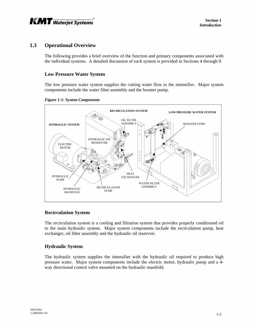
The low pressure water system supplies the cutting water flow to the intensifier. Major system components include the water filter assembly and the booster pump.
Figure 1-1: System Components
Recirculation System
The recirculation system is a cooling and filtration system that provides properly conditioned oil to the main hydraulic system. Major system components include the recirculation pump, heat exchanger, oil filter assembly and the hydraulic oil reservoir.
Hydraulic System
The hydraulic system supplies the intensifier with the hydraulic oil required to produce high pressure water. Major system components include the electric motor, hydraulic pump and a 4-way directional control valve mounted on the hydraulic manifold.
LOW PRESSURE WATER SYSTEM
OIL FILTERASSEMBLY
HEAT EXCHANGER
RECIRCULATIONPUMP
HYDRAULIC MANIFOLD
HYDRAULIC PUMP
ELECTRIC MOTOR
RECIRCULATION SYSTEM
HYDRAULIC SYSTEM BOOSTER PUMP
WATER FILTERASSEMBLY
HYDRAULIC OIL RESERVOIR
Section 1 Introduction
20412914 1-2006/Rev 03 1-4
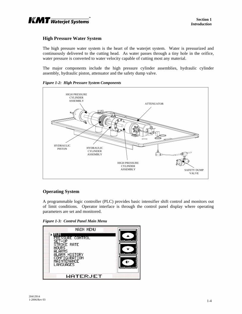
High Pressure Water System
The high pressure water system is the heart of the waterjet system. Water is pressurized and continuously delivered to the cutting head. As water passes through a tiny hole in the orifice, water pressure is converted to water velocity capable of cutting most any material.
The major components include the high pressure cylinder assemblies, hydraulic cylinder assembly, hydraulic piston, attenuator and the safety dump valve.
Figure 1-2: High Pressure System Components
Operating System
A programmable logic controller (PLC) provides basic intensifier shift control and monitors out of limit conditions. Operator interface is through the control panel display where operating parameters are set and monitored.
Figure 1-3: Control Panel Main Menu
HIGH PRESSURE CYLINDER ASSEMBLY
ATTENUATOR
HYDRAULIC PISTON HYDRAULIC
CYLINDER ASSEMBLY
HIGH PRESSURE CYLINDER ASSEMBLY SAFETY DUMP
VALVE
Section 1 Introduction
20412914 1-2006/Rev 03 1-5
1.4 Safety
The high pressure waterjet cutting system is a high energy cutting tool capable of cutting many dense or strong materials. Do not touch or be exposed to high pressure water. High pressure water will penetrate all parts of the human body. The liquid stream and the material ejected by the extreme pressure can result in severe injury.
All personnel operating, servicing or working near the waterjet cutting equipment shall adhere to the following safety precautions, as well as the applicable plant safety precautions.
• Only KMT factory trained, qualified personnel shall service and maintain the equipment.
• The operator shall practice and promote safety at all times to avoid potential injury and unnecessary downtime.
• The work area around the equipment shall be clean and free of debris and oil spills.
• All protective guards, shields or covers shall be in place on the equipment at all times.
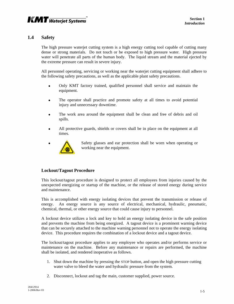
•
Safety glasses and ear protection shall be worn when operating or working near the equipment.
Lockout/Tagout Procedure
This lockout/tagout procedure is designed to protect all employees from injuries caused by the unexpected energizing or startup of the machine, or the release of stored energy during service and maintenance.
This is accomplished with energy isolating devices that prevent the transmission or release of energy. An energy source is any source of electrical, mechanical, hydraulic, pneumatic, chemical, thermal, or other energy source that could cause injury to personnel.
A lockout device utilizes a lock and key to hold an energy isolating device in the safe position and prevents the machine from being energized. A tagout device is a prominent warning device that can be securely attached to the machine warning personnel not to operate the energy isolating device. This procedure requires the combination of a lockout device and a tagout device.
The lockout/tagout procedure applies to any employee who operates and/or performs service or maintenance on the machine. Before any maintenance or repairs are performed, the machine shall be isolated, and rendered inoperative as follows.
1. Shut down the machine by pressing the STOP button, and open the high pressure cutting water valve to bleed the water and hydraulic pressure from the system.
2. Disconnect, lockout and tag the main, customer supplied, power source.
Section 1 Introduction
20412914 1-2006/Rev 03 1-6
3. Lockout and tag the circuit breaker/disconnect on the electrical enclosure door.
4. Close, lockout and tag the manual shutoff valves for all service connections: cutting water in, cooling water in and out, and air.
Warning Labels
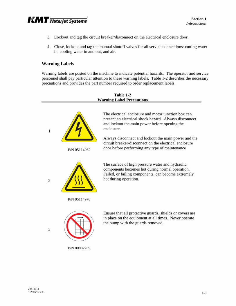
Warning labels are posted on the machine to indicate potential hazards. The operator and service personnel shall pay particular attention to these warning labels. Table 1-2 describes the necessary precautions and provides the part number required to order replacement labels.
Table 1-2 Warning Label Precautions
1
P/N 05114962
The electrical enclosure and motor junction box can present an electrical shock hazard. Always disconnect and lockout the main power before opening the enclosure.
Always disconnect and lockout the main power and the circuit breaker/disconnect on the electrical enclosure door before performing any type of maintenance
2
P/N 05114970
The surface of high pressure water and hydraulic components becomes hot during normal operation. Failed, or failing components, can become extremely hot during operation.
3
P/N 80082209
Ensure that all protective guards, shields or covers are in place on the equipment at all times. Never operate the pump with the guards removed.
Section 1 Introduction
20412914 1-2006/Rev 03 1-7
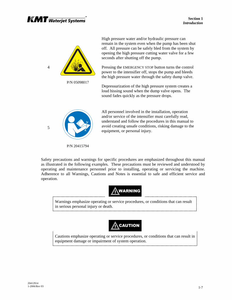
P/N 05098017
4
High pressure water and/or hydraulic pressure can remain in the system even when the pump has been shut off. All pressure can be safely bled from the system by opening the high pressure cutting water valve for a few seconds after shutting off the pump.
Pressing the EMERGENCY STOP button turns the control power to the intensifier off, stops the pump and bleeds the high pressure water through the safety dump valve.
Depressurization of the high pressure system creates a loud hissing sound when the dump valve opens. The sound fades quickly as the pressure drops.
5
P/N 20415794
All personnel involved in the installation, operation and/or service of the intensifier must carefully read, understand and follow the procedures in this manual to avoid creating unsafe conditions, risking damage to the equipment, or personal injury.
Safety precautions and warnings for specific procedures are emphasized throughout this manual as illustrated in the following examples. These precautions must be reviewed and understood by operating and maintenance personnel prior to installing, operating or servicing the machine. Adherence to all Warnings, Cautions and Notes is essential to safe and efficient service and operation.
Warnings emphasize operating or service procedures, or conditions that can result in serious personal injury or death.
Cautions emphasize operating or service procedures, or conditions that can result in equipment damage or impairment of system operation.

Section 1 Introduction
20412914 1-2006/Rev 03 1-8
NOTE
Notes provide additional information that can expedite or improve operating or service procedures.
Emergency Medical Treatment
An emergency medical card is included in the binder of this manual. This information should be used to aid in the treatment of a waterjet injury. Additional cards may be obtained by contacting KMT Waterjet Systems using the address or telephone number shown on the card.
Medical Alert This card is to be carried by personnel working with high pressure waterjet equipment. Obtain medical treatment immediately for ANY high
pressure waterjet injuries.
KMT Waterjet Systems 635 West 12th Street
Baxter Springs, KS 66713 (620) 856-2151
This person has been working with water jetting at pressures to 60,000 psi (374MPa, 4,137 bar, 3867
Kg/cm2) with a jet velocity of 3,000 fps (914 mps). Foreign material (sand) may have been injected with
water. Unusual infections with microaerophilic organisms occurring at lower temperatures have been
reported, such as gram negative pathogens as are found in sewage. Bacterial swabs and blood cultures may therefore be helpful. This injury must be treated as an acute surgical emergency and be evaluated by a qualified surgeon. Circulation may be compromised,
therefore, DO NOT APPLY HEAT TO INJURED PART. For first aid: (1) Elevate injured part (2)
Antibiotics (3) Keep injured person NPO.
Section 1 Introduction
20412914 1-2006/Rev 03 1-9
1.5 Worldwide Product Support
The KMT Waterjet Customer Service Department is available to answer your questions regarding equipment installation and service. Technical assistance is available by phone and on-site support is available on request.
On-site technical assistance is available during equipment installation and startup. Additionally, technical support for service and maintenance issues and training of operators and maintenance personnel is available. Periodic training sessions are also conducted at KMT Waterjet and customer facilities.
Contact the KMT Waterjet Customer Service Department for additional information.
USA Customer Service Manager Europe Technical Manager
KMT Waterjet Systems 635 West 12th Street Baxter Springs, KS 66713 USA
Phone: (620) 856-2151 Fax: (620) 856-5050 Email: [email protected]
KMT Waterjet Systems GmbH Wasserstrahl-Schneidetechnik Auf der Laukert 11 D-61231 Bad Nauheim Germany
Phone: +49-6032-997-117 Fax: +49-6032-997-270 Email: [email protected]
1.6 Spare Parts
KMT Waterjet maintains a well-stocked Spare Parts Department, staffed by trained, knowledgeable personnel. If required, emergency shipment is available. Contact the Customer Service Department to order spare parts, or for additional information.
1.7 Manual Organization
This manual contains operating and maintenance procedures for the complete SL-V series. Information is organized as follows:
• Section 1, Introduction, provides an overview of equipment features and options, a brief operational overview, details regarding safety issues and contact information for product support.
• Section 2, Installation, details installation requirements and procedures. Systematic guidelines for commissioning the intensifier are also provided.
• Section 3, Maintenance, highlights routine and preventive maintenance requirements. Precautions associated with high pressure cutting equipment are also reviewed.
• Section 4, Operation, explains the control functions and the display panel where operating parameters are set and monitored.

Section 1 Introduction
20412914 1-2006/Rev 03 1-10
• Sections 5 through 9 are specific to each individual system. Each section contains a detailed description of the principles of operation and the function of each system. Specifications and troubleshooting guidelines are provided, as well as routine maintenance procedures associated with the system.
• Section 10, Troubleshooting, is a comprehensive guide containing the information required to diagnose problems and repair the machine.
• Section 11, Specifications, contains a comprehensive list of equipment specifications; a detailed discussion of water quality standards and treatment guidelines; as well as horsepower requirements for various orifice sizes.
• Section 12, Parts List, contains part numbers, descriptions and drawings to facilitate the ordering of replacement parts.
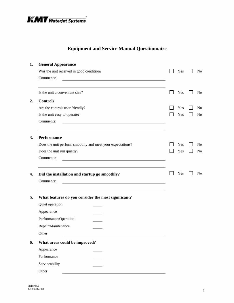
1.8 Equipment and Service Manual Questionnaire
We are interested in your impression of the KMT Waterjet System recently installed at your location. Your comments and recommendations will aid us in our continuing goal to improve our products, and make our technical information more useful to our customers.
At your convenience, please take a few minutes to complete the following questionnaire, and return it to the applicable Customer Service Department listed above.
20412914 1-2006/Rev 03 1
Equipment and Service Manual Questionnaire
1. General Appearance Was the unit received in good condition? Yes No
Comments:
Is the unit a convenient size? Yes No
2. Controls Are the controls user friendly? Yes No
Is the unit easy to operate? Yes No
Comments:
3. Performance Does the unit perform smoothly and meet your expectations? Yes No
Does the unit run quietly? Yes No
Comments:
4. Did the installation and startup go smoothly? Yes No
Comments:
5. What features do you consider the most significant? Quiet operation
Appearance
Performance/Operation
Repair/Maintenance
Other
6. What areas could be improved? Appearance
Performance
Serviceability
Other

Equipment and Service Manual Questionnaire
20412914 1-2006/Rev 03 2
7. Manual Organization Does the Table of Contents help you find topics easily? Yes No
Comments:
Is the information well organized? Yes No
Comments:
Is the page layout suitable for the material being presented? Yes No
Comments:
8. Graphics Are the illustrations suitable for the material being presented? Yes No
Comments:
9. Text Does the information adequately explain how to operate and service the
equipment? Yes No
Comments:
Are there paragraphs or procedures you feel need clarification? Please identify them by page number and add your comments. Yes No
Comments:
Is there anything you would add or delete to make the manual more useful? Yes No
Comments:
Is there any information that should receive more emphasis? Yes No
Comments:
Name Title
Company Date
Address
20412922 1-2006/Rev 03 2-1
SECTION 2 INSTALLATION
2.1 Overview
Installation and commissioning requirements and procedures are detailed in this section. These procedures require a thorough understanding of the individual components and systems, safety issues, and the overall operation of the intensifier.
All personnel involved in the installation, operation and/or service of the intensifier must carefully review this manual prior to installing and commissioning the machine.
The Technical Service Department at KMT Waterjet Systems is available to assist in the installation and commissioning process. Service and repair training for maintenance personnel is also available.
2.2 Installation Summary
The following summary lists the procedures required for the installation and commissioning of the intensifier system. Details and requirements for each item are discussed in this section.
• Upon receipt, the machine must be uncrated and moved into position on a level surface.
• Properly sized power drops with fused disconnects must be installed.
• A pneumatic drop with a manual shutoff valve and regulator for the air connection must be installed.
• Plumbing and manual shutoff valves for the inlet and outlet cooling water, and the inlet and outlet cutting water must be installed.
Incoming source water must meet specific water quality standards, flow rates and pressure requirements. It may be necessary to install water conditioning and/or pressure boosting equipment to meet these water purity and pressure requirements.
• Drain water plumbing must be suitably located and installed for the proper disposal of wastewater.
• High pressure tubing runs from the intensifier to the cutting station must be installed with the appropriate mountings, support brackets and hardware.
• Wiring must be installed and connected between the intensifier and the cutting station control system.
• The machine must be commissioned and tested.
Section 2 Installation
20412922 1-2006/Rev 03 2-2
2.3 Site Requirements
The intensifier must be installed indoors where air borne dust and contaminants are minimal. The ambient temperature should be between 40° F (5° C) and 104° F (40° C), with a maximum relative humidity of 95%.
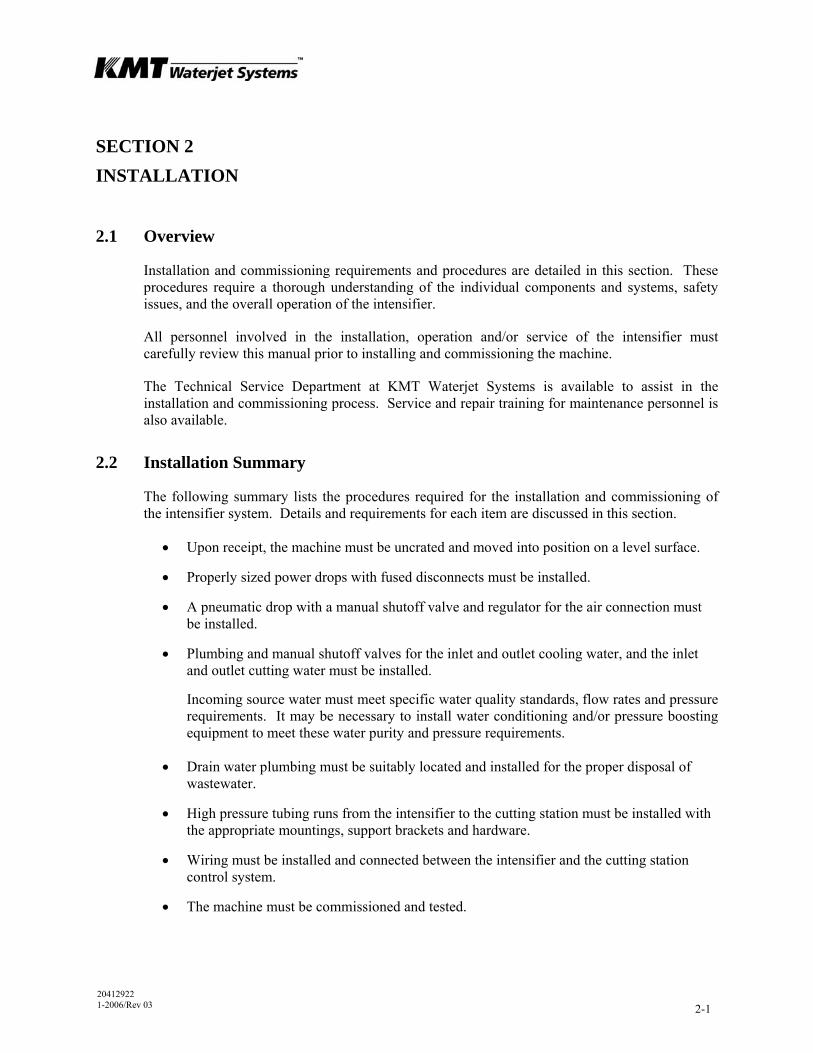
Refer to Table 2-1, Equipment Dimensions and Weight, to establish a suitable installation site. A minimum clearance of 36 inches (914 mm) should be provided on all sides of the machine to facilitate service.
Figure 2-1: Equipment Dimensions
Table 2-1 Equipment Dimensions and Weight
Horsepower Length Width Height Weight
30 HP 67.75” (1,721 mm) 36.00” (914 mm) 57.19” (1,453 mm) 2,100 lbs (953 kg)
50 HP 67.75” (1,721 mm) 36.00” (914 mm) 57.19” (1,453 mm) 2,900 lbs (1,315 kg)
60 HP 77.75” (1,975 mm) 36.00” (914 mm) 57.19” (1,453 mm) 3,400 lbs (1,542 kg)
75 HP 77.75” (1,975 mm) 36.00” (914 mm) 57.19” (1,453 mm) 3,800 lbs (1,724 kg)
100 HP 77.75” (1,975 mm) 36.00” (914 mm) 57.19” (1,453 mm) 4,200 lbs (1,905 kg)
100D 77.75” (1,975 mm) 36.00” (914 mm) 57.19” (1,453 mm) 4,300 lbs (1,950 kg)
Redundant Models (same dimensions as above)
30 HP 2,380 lbs (1,080 kg)
50 HP 3,180 lbs (1,442 kg)
60 HP 3,680 lbs (1,669 kg)
LENGTH
WIDTH
HEIGHT
Section 2 Installation
20412922 1-2006/Rev 03 2-3
Table 2-1 Equipment Dimensions and Weight
Horsepower Length Width Height Weight
75 HP 4,200 lbs (1,905 kg)
100 HP 4,600 lbs (2,087 kg)
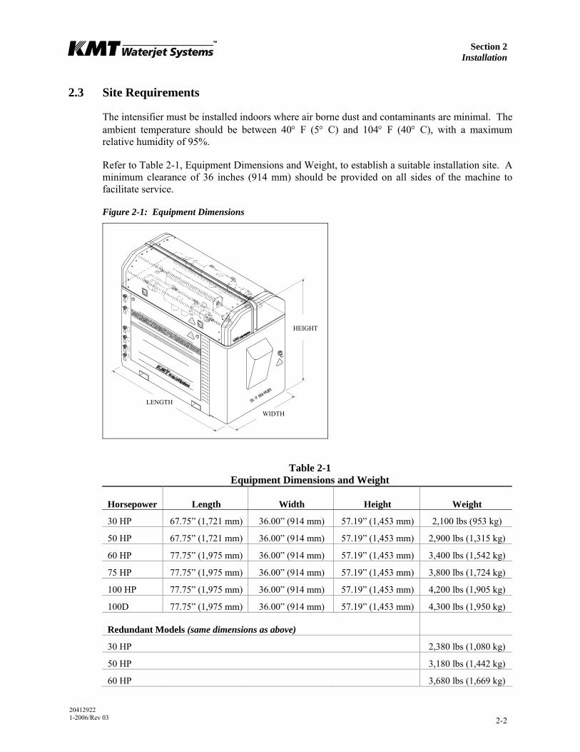
Transporting
The weight of the machine is not evenly distributed from one end to the other, particularly on the larger horsepower models. Do not attempt to lift the machine from either end. Note the warnings stamped on the crate. The center of gravity is clearly identified on the sides of the crate. The forklift should be positioned accordingly.
When the machine has been removed from the crate, note the position of the fork pockets on the bottom of the machine. The pockets are positioned in relationship to the center of gravity to balance the weight on the forklift.
Figure 2-2: Fork Pockets

Section 2 Installation
20412922 1-2006/Rev 03 2-4
Table 2-2 Fork Pockets
30/50 HP 60/75/100 HP 100D
A Fork Pocket Dimensions
Height 3.0” (76.2 mm) 3.0” (76.2 mm) 3.0” (76.2 mm)
Width 6.0” (152.4 mm) 6.0” (152.4 mm) 6.0” (152.4 mm)
Length 36.75” (933.45 mm) 36.75” (933.45 mm) 36.75” (933.45 mm)
B Distance Between Pockets 34.0” (863.6 mm) 36.0” (914.4 mm) 36.0” (914.4 mm)
If the machine will be installed in an overhead location, a forklift or crane can be used to position the pump. Heavy straps or chains, properly rated for the weight requirements, should be placed through each fork pocket, and wrapped around the sides of the machine so they meet on the top. The straps can then be attached to a crane or forklift to lift the machine.
The machine must be lifted from the bottom. Do not attempt to lift the machine from the intensifier.
2.4 Power Requirements
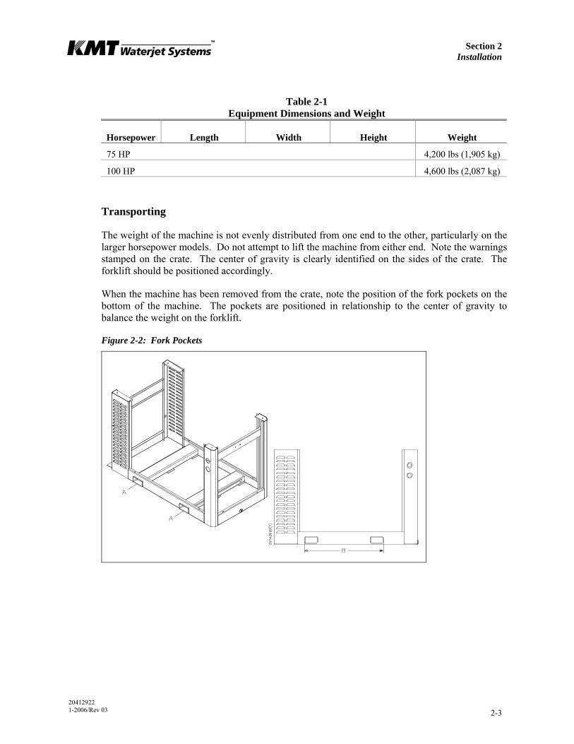
Power supplied to the pump and wiring for remote control must comply with local, regional and national electrical codes. Service voltage and ampacity must meet the requirements of the specific model. Voltage fluctuations in excess of +/- 10 percent of nominal voltage may damage the machine and void the warranty. Refer to Table 2-3, Ampacity and Power Voltage Requirements.
Table 2-3 Ampacity and Power Voltage Requirements
Power Voltage
Motor Horsepower
Full Load Amps
Circuit Breaker Amps
208/3/50-60 30 86 125
230/3/60 30 76 100
400/3/50 30 42 80
415/3/50 30 43 80
460/3/60 30 38 50
575/3/60 30 32 50
200/3/50-60 50 132 175
Section 2 Installation
20412922 1-2006/Rev 03 2-5
Table 2-3 Ampacity and Power Voltage Requirements
Power Voltage
Motor Horsepower
Full Load Amps
Circuit Breaker Amps
208/3/50-60 50 128 175
230/3/60 50 122 175
380/3/50 50 69 100
400/3/50 50 66 100
415/3/50 50 64 100
460/3/60 50 58 80
575/3/60 50 52 80
230/3/60 60 142 175
380/3/60 60 83 125
460/3/60 60 71 100
200/3/50-60 75 198 250
230/3/60 75 172 250
400/3/50 75 98 175
460/3/60 75 86 100
230/3/60 100 248 300
400/3/50 100 124 175
415/3/50 100 120 175
480/3/60 100 105 175
575/3/60 100 99 125
Section 2 Installation
20412922 1-2006/Rev 03 2-6
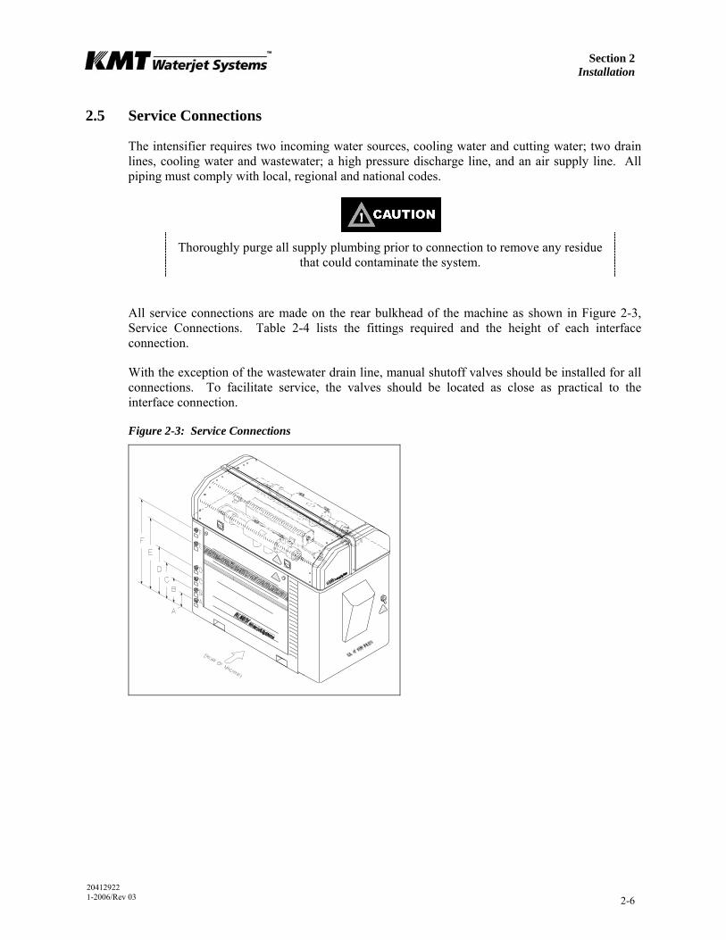
2.5 Service Connections
The intensifier requires two incoming water sources, cooling water and cutting water; two drain lines, cooling water and wastewater; a high pressure discharge line, and an air supply line. All piping must comply with local, regional and national codes.
Thoroughly purge all supply plumbing prior to connection to remove any residue that could contaminate the system.
All service connections are made on the rear bulkhead of the machine as shown in Figure 2-3, Service Connections. Table 2-4 lists the fittings required and the height of each interface connection.
With the exception of the wastewater drain line, manual shutoff valves should be installed for all connections. To facilitate service, the valves should be located as close as practical to the interface connection.
Figure 2-3: Service Connections
Section 2 Installation
20412922 1-2006/Rev 03 2-7
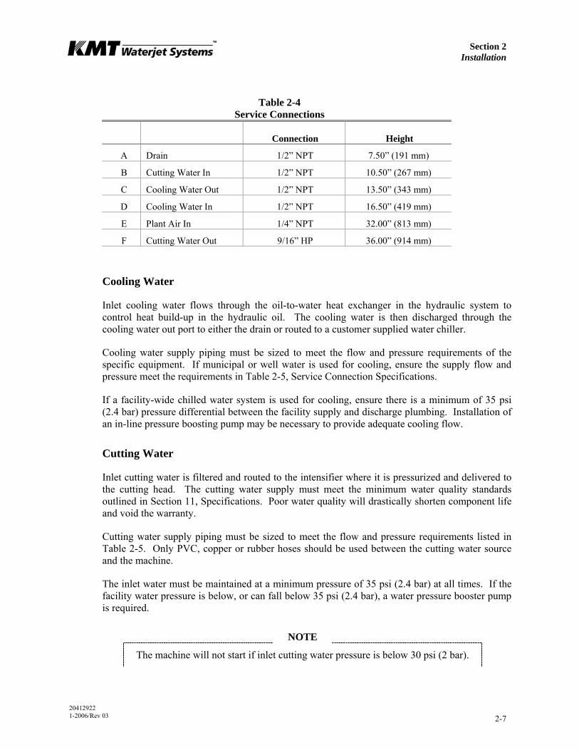
Table 2-4 Service Connections
Connection Height
A Drain 1/2” NPT 7.50” (191 mm)
B Cutting Water In 1/2” NPT 10.50” (267 mm)
C Cooling Water Out 1/2” NPT 13.50” (343 mm)
D Cooling Water In 1/2” NPT 16.50” (419 mm)
E Plant Air In 1/4” NPT 32.00” (813 mm)
F Cutting Water Out 9/16” HP 36.00” (914 mm)
Cooling Water
Inlet cooling water flows through the oil-to-water heat exchanger in the hydraulic system to control heat build-up in the hydraulic oil. The cooling water is then discharged through the cooling water out port to either the drain or routed to a customer supplied water chiller.
Cooling water supply piping must be sized to meet the flow and pressure requirements of the specific equipment. If municipal or well water is used for cooling, ensure the supply flow and pressure meet the requirements in Table 2-5, Service Connection Specifications.
If a facility-wide chilled water system is used for cooling, ensure there is a minimum of 35 psi (2.4 bar) pressure differential between the facility supply and discharge plumbing. Installation of an in-line pressure boosting pump may be necessary to provide adequate cooling flow.
Cutting Water
Inlet cutting water is filtered and routed to the intensifier where it is pressurized and delivered to the cutting head. The cutting water supply must meet the minimum water quality standards outlined in Section 11, Specifications. Poor water quality will drastically shorten component life and void the warranty.
Cutting water supply piping must be sized to meet the flow and pressure requirements listed in Table 2-5. Only PVC, copper or rubber hoses should be used between the cutting water source and the machine.
The inlet water must be maintained at a minimum pressure of 35 psi (2.4 bar) at all times. If the facility water pressure is below, or can fall below 35 psi (2.4 bar), a water pressure booster pump is required.
NOTE
The machine will not start if inlet cutting water pressure is below 30 psi (2 bar).
Section 2 Installation
20412922 1-2006/Rev 03 2-8
Drain
Cutting water released through the safety dump valve when the emergency stop button is initiated is discharged from the drain port. The discharge is considered wastewater and must be piped to an appropriate location, i.e. a sewer line. The volume of water released will be minimal and does not require high pressure plumbing, however, piping must comply with local, regional and national codes.
Plant Air
The facility compressed air connection should provide clean, dry air regulated to 85 psi (5.9 bar). Air usage is minimal, normally less than 1 scf/m.
Table 2-5 Service Connection Specifications
30 HP 50 HP 60 HP 75 HP 100 HP 100D
Cooling Water
Maximum consumption at 75° F (24° C) [gpm (L/min)]
2.5 (9.5)
3.0 (11.4)
3.5 (13.2)
4.0 (15.1)
4.5 (17.0)
4.5 (17.0)
Minimum inlet pressure 35 psi (2.4 bar)
Cutting Water
Maximum consumption [gpm (L/min)]
2.5 (9.5)
4.0 (15.1)
4.5 (17.0)
6.0 (22.7)
8.0 (30.0)
8.0 (30.0)
Minimum inlet pressure 35 psi (2.4 bar) flowing
Compressed Air
Minimum air pressure 85 psi (5.9 bar)
2.6 Flow Requirements
Figure 2-4, Pressure Drop Values, illustrates the pressure drop for four different pipe sizes. The graph can be used to calculate the minimum source water pressure.
1. Enter the graph at the required GPM and note the pressure drop figures for the different pipe sizes.
2. Multiply the pressure drop (PSI/FT) by the length in feet of each pipe size used from the water source to the intensifier. Add the values together for a total pressure drop value.
3. Add 30 to the total pressure drop to determine the minimum flowing, source water pressure required to provide adequate supply to the intensifier.

Section 2 Installation
20412922 1-2006/Rev 03 2-9
Cutting water and cooling water capacity should be calculated separately. Note that the cutting water requirements represent instantaneous, not average, demand. The machine will not start if the inlet cutting water pressure drops below 30 psi (2 bar).
Figure 2-4: Pressure Drop Values
Pipe Sizing
00.05
0.10.15
0.20.25
0.30.35
0.40.45
0 1 2 3 4 5 6 7 8 9 10 11 12 13 14 15 16 17 18 19 20
Required GPM
Pres
sure
dro
p (P
SI/F
T)
1/2" ID
3/4" ID
1" ID
1-1/4" ID
2.7 High Pressure Piping
High pressure piping is used to transport high pressure cutting water from the machine to the cutting station. High pressure piping and fittings must be properly rated and sized. When transporting high pressure water over long distances, tubing and fittings with an outside diameter of 9/16-inch are recommended. The large tubing size reduces vibration, strain and motion; as well as reducing pressure drop and pulsation.
High pressure tubing and fittings must be rated for 60,000 psi (4,136 bar). Failure to use properly rated components may result in component failure causing
equipment damage, personal injury or death.
High pressure tubing lengths must be coned and threaded prior to installation. KMT Waterjet provides both hand and power tools for coning and threading high pressure tubing. Tool descriptions and part numbers are provided in Table 2-6.

Section 2 Installation
20412922 1-2006/Rev 03 2-10
Table 2-6 Coning and Threading Tools
Part Number
Hand Tools Power Tools
1/4” Coning Tool 05108832 05109897
3/8” Coning Tool 05108857 05109889
9/16” Coning Tool 05108840 05109871
1/4” Threading Tool 05108865 05122742
3/8” Threading Tool 05108873 05120258
9/16” Threading Tool 05108881 05122759
1/4” Tube Vise 05108782
3/8” Tube Vise 05108790
9/16” Tube Vise 05108774
Measurements and Dimensions
Tubing must be cut to the proper length, both ends of the tubing must then be coned, threaded and deburred.
To determine the tube length, measure the distance between the fittings, and add two times the engagement allowance shown in Table 2-7. Table 2-8 lists the required cone and thread dimensions illustrated in Figure 2-6.
Figure 2-5: Tube Length
Table 2-7 Engagement Allowance (EA)
1/4” Tubing 0.49” (12.4 mm)
3/8” Tubing 0.68” (17.3 mm)
9/16” Tubing 0.86” (21.8 mm)
TUBE LENGTH = LENGTH + 2(EA)
LENGTH
Section 2 Installation
20412922 1-2006/Rev 03 2-11
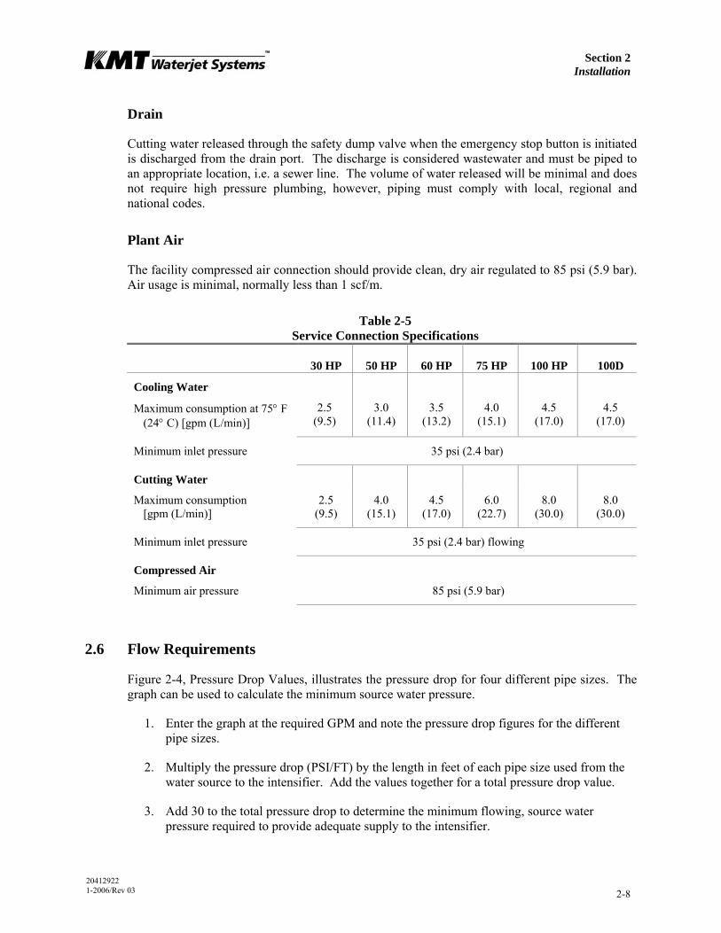
Figure 2-6: Cone and Thread Dimensions
Table 2-8 Cone and Thread Dimensions
Tube OD
Tube ID
D (Maximum)
L (Maximum)
Thread UNF-LH
1/4” (6.35 mm) 0.083” (2.11 mm) 0.125” (3.2 mm) 0.562” (14.3 mm) 1/4” - 28
3/8” (9.52 mm) 0.125” (3.18 mm 0.219” (5.6 mm) 0.750” (19.1 mm) 3/8” - 24
9/16” (14.29 mm) 0.188” (4.78 mm) 0.281” (7.1 mm) 0.938” (23.8 mm) 9/16” - 18
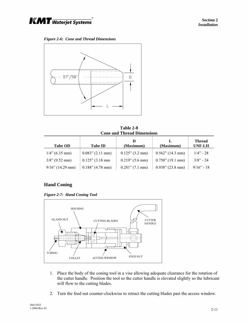
Hand Coning
Figure 2-7: Hand Coning Tool
1. Place the body of the coning tool in a vise allowing adequate clearance for the rotation of the cutter handle. Position the tool so the cutter handle is elevated slightly so the lubricant will flow to the cutting blades.
2. Turn the feed nut counter-clockwise to retract the cutting blades past the access window.
FEED NUT
CUTTING BLADES CUTTERHANDLE
ACCESS WINDOW COLLET
HOUSING
GLAND NUT
TUBING
Section 2 Installation
20412922 1-2006/Rev 03 2-12
3. Loosen the gland nut and insert the tubing through the collet. The end of the tubing should just make contact with the cutting blades. Loosely tighten the gland nut to slightly grip the tubing.
4. Turn the feed nut counter-clockwise 1/4 turn to retract the cutting blades away from the tubing, and tighten the gland nut with a wrench.
5. Apply a liberal amount of cutting oil to the exposed end of the tubing, the cutting blades and through the lubrication channel at the cutter handle.
Apply cutting oil frequently and liberally throughout the cutting operation. A medium weight cutting oil with high sulfur content is recommended.
6. Turn the feed nut clockwise until the cutting blades contact the end of the tubing.
7. In a smooth, continuous motion, turn the cutter handle in a clockwise direction. Simultaneously turn the feed nut in a clockwise direction to establish a constant feed. Do not remove too much material at once; the cutting blades should make light, uninterrupted cuts.
NOTE
Before interrupting the cut, back the cutter blades away from the tubing. Use compressed air or a small brush to remove the accumulation of chips from the
blades and the tubing throughout the coning operation.
8. Continue the operation until the feed nut bottoms on the housing. Turn the cutter handle several more rotations to face-off the end of the cone.
9. Retract the cutter blades, loosen the gland nut and remove the tubing. Inspect the cone for surface finish and completeness.
NOTE
Clean the machining chips from the blade and from the collet before coning the next tube.
Power Coning
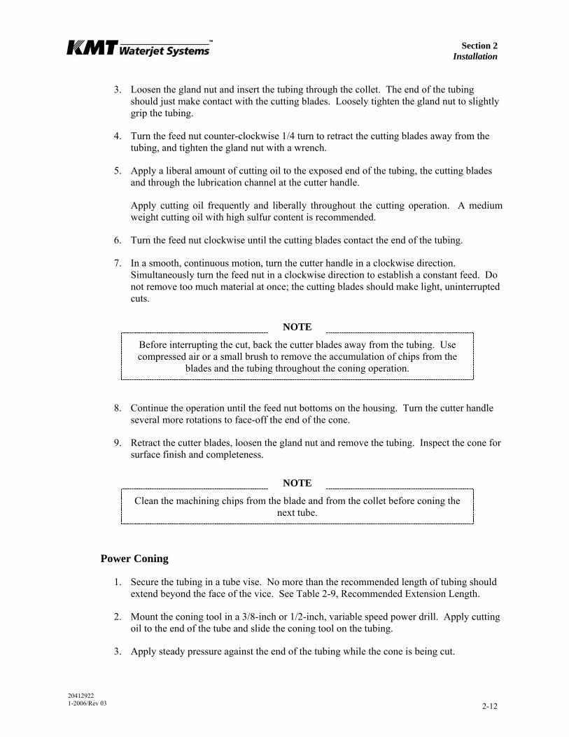
1. Secure the tubing in a tube vise. No more than the recommended length of tubing should extend beyond the face of the vice. See Table 2-9, Recommended Extension Length.
2. Mount the coning tool in a 3/8-inch or 1/2-inch, variable speed power drill. Apply cutting oil to the end of the tube and slide the coning tool on the tubing.
3. Apply steady pressure against the end of the tubing while the cone is being cut.
Section 2 Installation
20412922 1-2006/Rev 03 2-13
Apply cutting oil frequently and liberally throughout the cutting operation. A medium weight cutting oil with high sulfur content is recommended.
4. The tool will stop cutting when the tube angle and facing is complete.
NOTE
Clean the machining chips from the blade and body of the tool before coning the next tube.
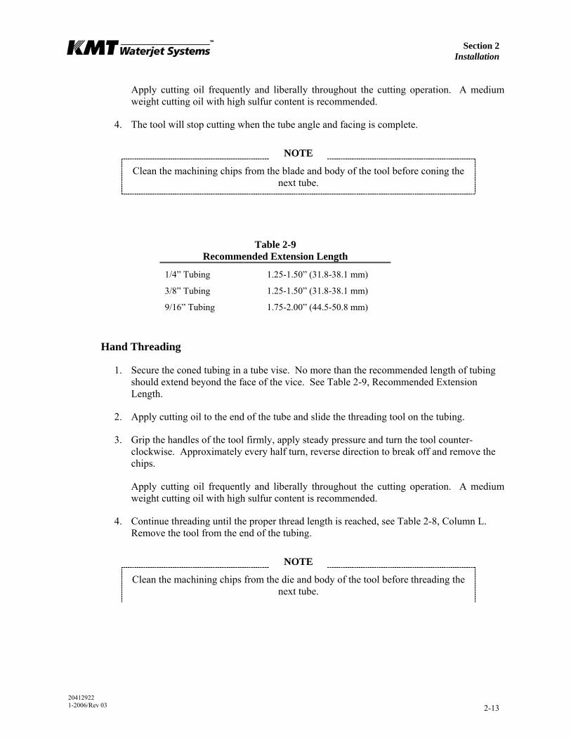
Table 2-9 Recommended Extension Length
1/4” Tubing 1.25-1.50” (31.8-38.1 mm)
3/8” Tubing 1.25-1.50” (31.8-38.1 mm)
9/16” Tubing 1.75-2.00” (44.5-50.8 mm)
Hand Threading
1. Secure the coned tubing in a tube vise. No more than the recommended length of tubing should extend beyond the face of the vice. See Table 2-9, Recommended Extension Length.
2. Apply cutting oil to the end of the tube and slide the threading tool on the tubing.
3. Grip the handles of the tool firmly, apply steady pressure and turn the tool counter-clockwise. Approximately every half turn, reverse direction to break off and remove the chips.
Apply cutting oil frequently and liberally throughout the cutting operation. A medium weight cutting oil with high sulfur content is recommended.
4. Continue threading until the proper thread length is reached, see Table 2-8, Column L. Remove the tool from the end of the tubing.
NOTE
Clean the machining chips from the die and body of the tool before threading the next tube.
Section 2 Installation
20412922 1-2006/Rev 03 2-14
Power Threading
1. Secure the coned tubing in a tube vise. No more than the recommended length of tubing should extend beyond the face of the vice. See Table 2-9, Recommended Extension Length.
2. Mount the threading tool in a 3/8-inch or 1/2-inch, variable speed power drill. Apply cutting oil to the end of the tube and slide the threading tool on the tubing.
3. Make sure the drill is set to turn counter-clockwise. Apply steady pressure against the end of the tubing while the threads are being cut.
Apply cutting oil frequently and liberally throughout the cutting operation. A medium weight cutting oil with high sulfur content is recommended.
4. Continue threading until the proper thread length is reached, see Table 2-8, Column L. Reverse the direction of the drill and remove the threading tool.
NOTE
Clean the machining chips from the die and body of the tool before threading the next tube.
2.8 High Pressure Connections
When installing high pressure discharge piping it is essential that all burrs be carefully removed and the tubing sections purged with clean compressed air prior to assembly. Lightly spraying the inside of the tube with a carrier fluid, such as WD-40, before purging with air will help carry the burrs.
High pressure piping must be installed without torsional or bending stresses and proper supports and guides must be provided. Torsional stress will cause premature component failure.
Pure Goop anti-seize compound must be applied to the threads and contact surfaces of all stainless steel components prior to assembly. Failure to lubricate components with Pure Goop will result in galling, rendering the components useless.
Do not use any other anti-seize compound. Apply Pure Goop only to stainless steel components.

Section 2 Installation
20412922 1-2006/Rev 03 2-15
Standard Connections
Standard connections are used for general applications where internal pressure is the only load on the tubing.
Figure 2-8: Standard High Pressure Connections
1. Deburr the tubing ID and thoroughly clean the tubing threads.
2. Slip the gland nut onto the tubing.
3. Apply Pure Goop to the threads on the tubing. Screw the collar onto the threaded end of the tubing leaving 1-1/2 to 2-1/2 threads exposed on the tubing between the collar and the coned tubing.
4. Apply Pure Goop to the male threads on the gland nut and insert the tubing into the connection. Engage the gland nut and tighten finger tight.
5. Tighten the gland nut to the torque specifications in Table 2-10.
Proper piping supports and guides must be provided. End connections will not support the tubing load alone.
Table 2-10 Torque Specifications
High Pressure Connections
1/4” Tubing 25 ft-lb (34 Nm)
3/8” Tubing 50 ft-lb (68 Nm)
9/16” Tubing 110 ft-lb (149 Nm)
COLLAR
TUBING
GLAND NUT
EXPOSED THREADS
Section 2 Installation
20412922 1-2006/Rev 03 2-16
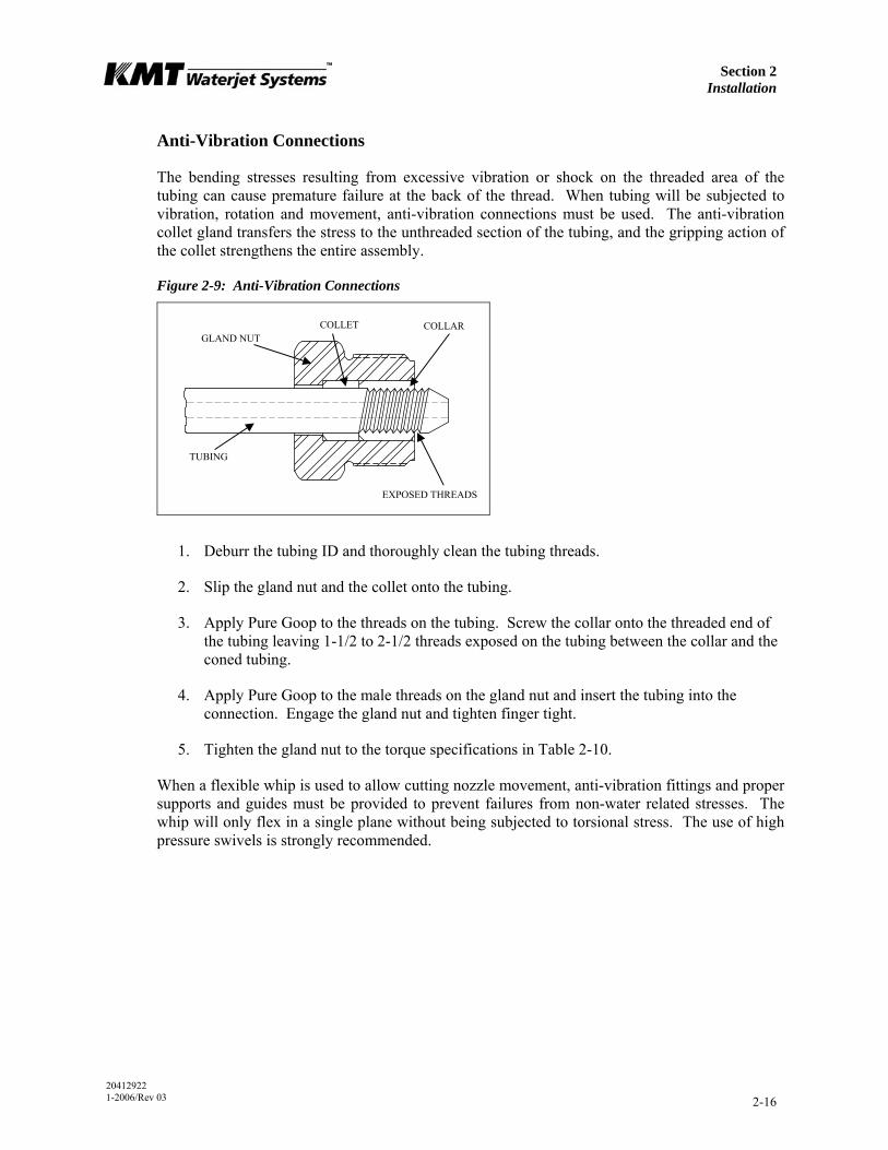
Anti-Vibration Connections
The bending stresses resulting from excessive vibration or shock on the threaded area of the tubing can cause premature failure at the back of the thread. When tubing will be subjected to vibration, rotation and movement, anti-vibration connections must be used. The anti-vibration collet gland transfers the stress to the unthreaded section of the tubing, and the gripping action of the collet strengthens the entire assembly.
Figure 2-9: Anti-Vibration Connections
1. Deburr the tubing ID and thoroughly clean the tubing threads.
2. Slip the gland nut and the collet onto the tubing.
3. Apply Pure Goop to the threads on the tubing. Screw the collar onto the threaded end of the tubing leaving 1-1/2 to 2-1/2 threads exposed on the tubing between the collar and the coned tubing.
4. Apply Pure Goop to the male threads on the gland nut and insert the tubing into the connection. Engage the gland nut and tighten finger tight.
5. Tighten the gland nut to the torque specifications in Table 2-10.
When a flexible whip is used to allow cutting nozzle movement, anti-vibration fittings and proper supports and guides must be provided to prevent failures from non-water related stresses. The whip will only flex in a single plane without being subjected to torsional stress. The use of high pressure swivels is strongly recommended.
COLLET
TUBING
COLLAR GLAND NUT
EXPOSED THREADS

Section 2 Installation
20412922 1-2006/Rev 03 2-17
2.9 Commissioning
When the machine has been positioned, all service connections installed, and the high pressure plumbing has been installed to the cutting area, the machine is ready to be commissioned.
If normal operating pressure will not exceed 50,000 psi (3,447 bar), the alternate inlet poppet valves on 30, 50, 60 and 100D models must be installed before
proceeding. Follow the procedure Low Pressure Inlet Check Valve, Section 9, High Pressure Water System. Refer to Table 12-4, Section 12, Parts List.
The following procedure is used for the initial startup and testing of the machine.
1. Check all areas in and around the pump for foreign objects and debris. Remove all tools, parts, etc. from the area.
2. Check the hydraulic fluid level. The hydraulic system is pre-filled prior to shipping. If the hydraulic fluid is low or empty due to leakage during transit, the system must be filled. Follow the instructions and specifications in Section 6, Recirculation System.
3. Open the shutoff valves on the service connections and check for leaks.
4. Check the connection between the main power disconnect and the disconnect/circuit break on the enclosure door. Verify the proper voltage supply. Close the enclosure door and turn the control power on.
5. To activate the control panel display, pull the EMERGENCY STOP button out and press the RESET button. The control panel will go through a series of diagnostics, and the Run Screen will display. Refer to Section 4, Operation, for additional information regarding control panel functions.
EMERGENCY STOP
RESET BUTTON
LOCAL/REMOTE SWITCH
Section 2 Installation
20412922 1-2006/Rev 03 2-18
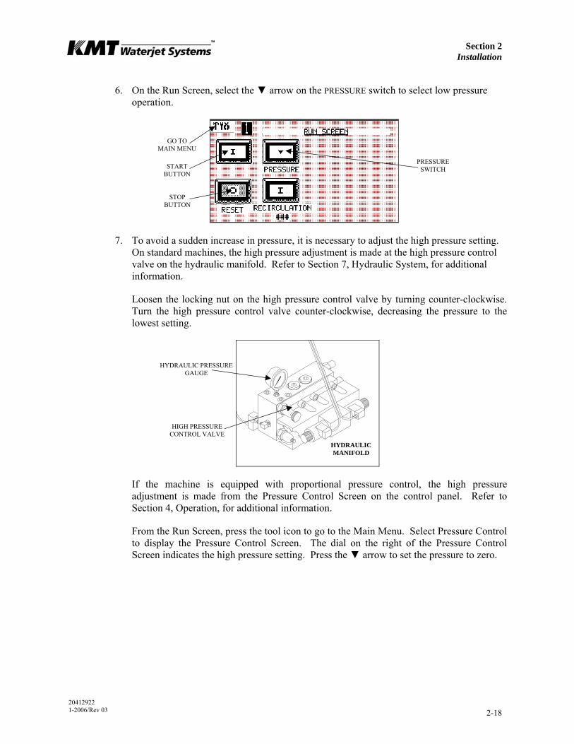
6. On the Run Screen, select the ▼ arrow on the PRESSURE switch to select low pressure operation.
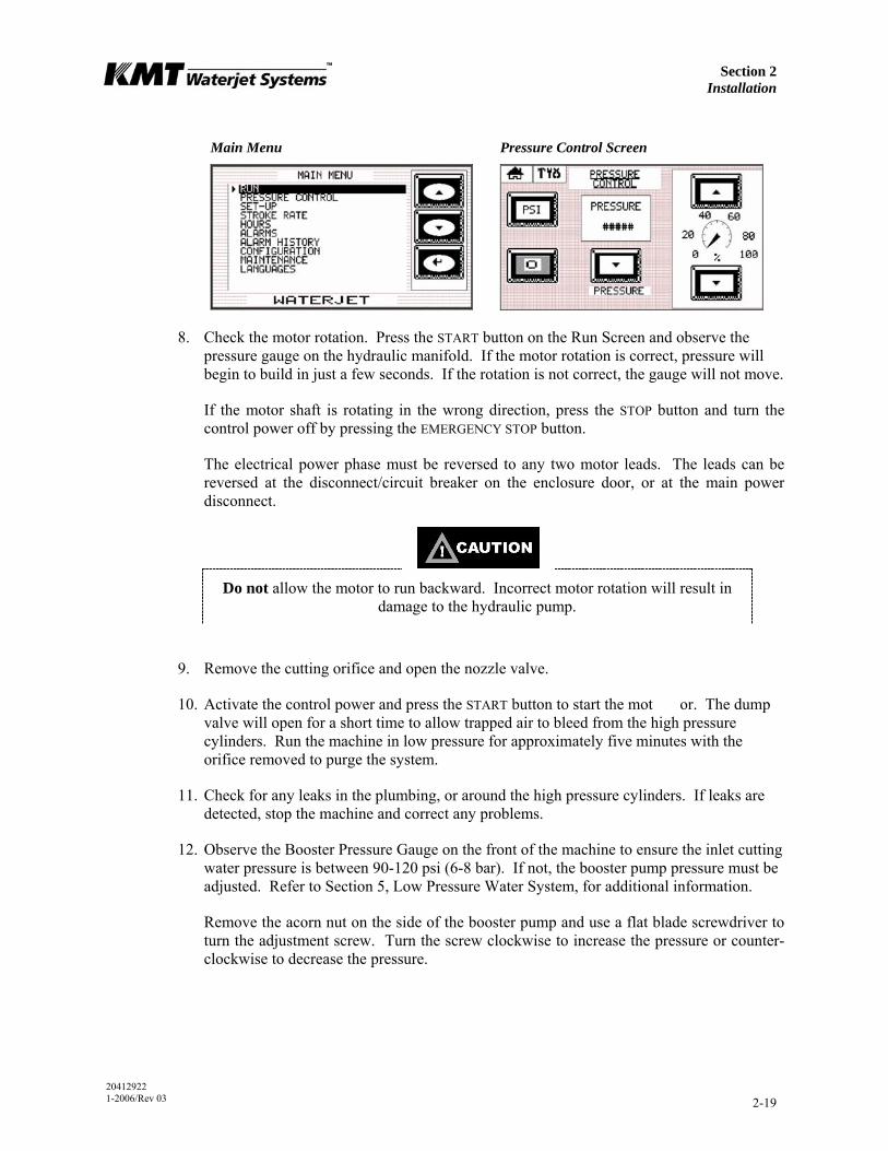
7. To avoid a sudden increase in pressure, it is necessary to adjust the high pressure setting. On standard machines, the high pressure adjustment is made at the high pressure control valve on the hydraulic manifold. Refer to Section 7, Hydraulic System, for additional information.
Loosen the locking nut on the high pressure control valve by turning counter-clockwise. Turn the high pressure control valve counter-clockwise, decreasing the pressure to the lowest setting.
If the machine is equipped with proportional pressure control, the high pressure adjustment is made from the Pressure Control Screen on the control panel. Refer to Section 4, Operation, for additional information.
From the Run Screen, press the tool icon to go to the Main Menu. Select Pressure Control to display the Pressure Control Screen. The dial on the right of the Pressure Control Screen indicates the high pressure setting. Press the ▼ arrow to set the pressure to zero.
PRESSURE SWITCH
STOP BUTTON
START BUTTON
GO TO MAIN MENU
HIGH PRESSURE CONTROL VALVE
HYDRAULIC MANIFOLD
HYDRAULIC PRESSURE GAUGE
Section 2 Installation
20412922 1-2006/Rev 03 2-19
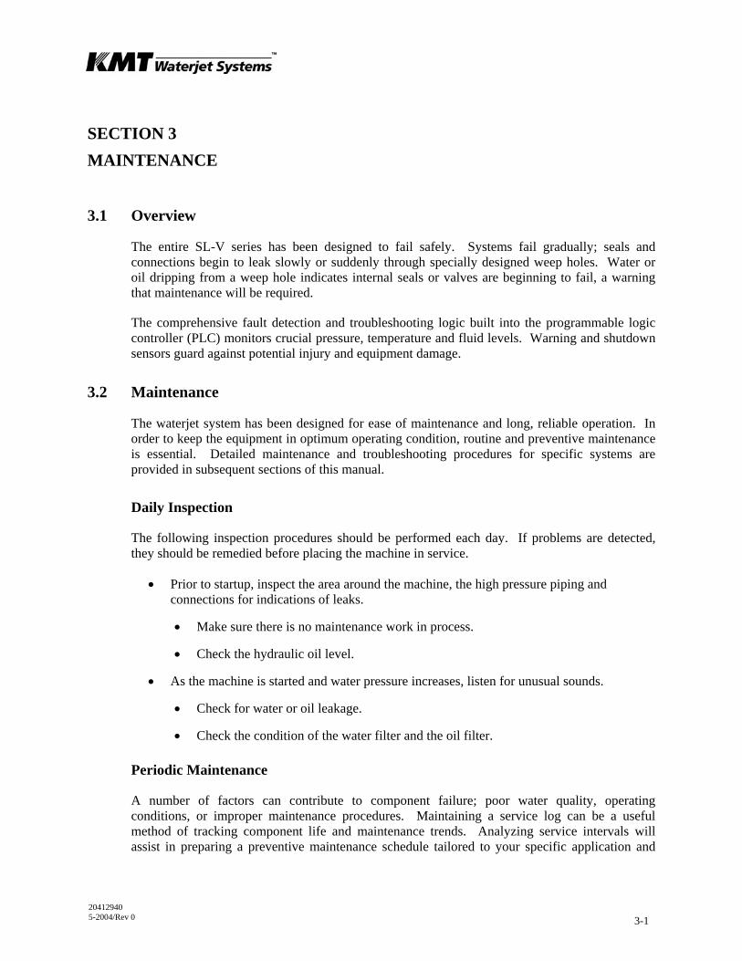
Main Menu Pressure Control Screen
8. Check the motor rotation. Press the START button on the Run Screen and observe the pressure gauge on the hydraulic manifold. If the motor rotation is correct, pressure will begin to build in just a few seconds. If the rotation is not correct, the gauge will not move.
If the motor shaft is rotating in the wrong direction, press the STOP button and turn the control power off by pressing the EMERGENCY STOP button.
The electrical power phase must be reversed to any two motor leads. The leads can be reversed at the disconnect/circuit breaker on the enclosure door, or at the main power disconnect.
Do not allow the motor to run backward. Incorrect motor rotation will result in damage to the hydraulic pump.
9. Remove the cutting orifice and open the nozzle valve.
10. Activate the control power and press the START button to start the mot or. The dump valve will open for a short time to allow trapped air to bleed from the high pressure cylinders. Run the machine in low pressure for approximately five minutes with the orifice removed to purge the system.
11. Check for any leaks in the plumbing, or around the high pressure cylinders. If leaks are detected, stop the machine and correct any problems.
12. Observe the Booster Pressure Gauge on the front of the machine to ensure the inlet cutting water pressure is between 90-120 psi (6-8 bar). If not, the booster pump pressure must be adjusted. Refer to Section 5, Low Pressure Water System, for additional information.
Remove the acorn nut on the side of the booster pump and use a flat blade screwdriver to turn the adjustment screw. Turn the screw clockwise to increase the pressure or counter-clockwise to decrease the pressure.

Section 2 Installation
20412922 1-2006/Rev 03 2-20
13. Check the safety circuits by pushing the EMERGENCY STOP button in and verifying that the power goes off and high pressure water is drained from the system. If applicable, check all remote start and emergency stop functions.
14. Install a large, inexpensive orifice and start the machine.
15. On the Run Screen, select the ▲ arrow on the PRESSURE switch to select high pressure operation. Increase the high pressure setting in gradual increments, checking for leaks at each interval. Continue increasing the pressure until the operating pressure is reached.
The high pressure setting is increased by turning the high pressure control valve on the hydraulic manifold clockwise, or by pressing the ▲ arrow on the Pressure Control Screen.
NOTE
It is strongly recommended that the high pressure plumbing be purged under high pressure operating conditions, using a large, inexpensive orifice. Contamination can be released when the tubing expands under pressure. Early orifice failures
could be experienced if the piping is not adequately purged.
2.10 Decommissioning
All local regulations must be adhered to when the intensifier is decommissioned and taken out of service for any reason.
ACORN NUT
BOOSTER PUMP
20412940 5-2004/Rev 0 3-1
SECTION 3 MAINTENANCE
3.1 Overview
The entire SL-V series has been designed to fail safely. Systems fail gradually; seals and connections begin to leak slowly or suddenly through specially designed weep holes. Water or oil dripping from a weep hole indicates internal seals or valves are beginning to fail, a warning that maintenance will be required.
The comprehensive fault detection and troubleshooting logic built into the programmable logic controller (PLC) monitors crucial pressure, temperature and fluid levels. Warning and shutdown sensors guard against potential injury and equipment damage.
3.2 Maintenance
The waterjet system has been designed for ease of maintenance and long, reliable operation. In order to keep the equipment in optimum operating condition, routine and preventive maintenance is essential. Detailed maintenance and troubleshooting procedures for specific systems are provided in subsequent sections of this manual.
Daily Inspection
The following inspection procedures should be performed each day. If problems are detected, they should be remedied before placing the machine in service.
• Prior to startup, inspect the area around the machine, the high pressure piping and connections for indications of leaks.
• Make sure there is no maintenance work in process.
• Check the hydraulic oil level.
• As the machine is started and water pressure increases, listen for unusual sounds.
• Check for water or oil leakage.
• Check the condition of the water filter and the oil filter.
Periodic Maintenance
A number of factors can contribute to component failure; poor water quality, operating conditions, or improper maintenance procedures. Maintaining a service log can be a useful method of tracking component life and maintenance trends. Analyzing service intervals will assist in preparing a preventive maintenance schedule tailored to your specific application and

Section 3 Maintenance
20412940 5-2004/Rev 0 3-2
production requirements. Periodic maintenance, at regularly scheduled intervals, will minimize unscheduled downtime and premature component failure.
Improper assembly can lead to the premature failure of components. Maintenance procedures must be followed carefully; components must be properly cleaned prior to assembly and tightened to the correct torque specifications.
• Maintain a clean, dust and dirt free work area for maintenance.
• Use only clean, dry air and clean, filtered solvent when flushing parts.
• Use lint free cloths for cleaning.
• Use extreme care when aligning close tolerance parts for assembly. Do not force the parts together. If parts bind during assembly, they must be disassembled and re-aligned.
• Use only original KMT Waterjet replacement parts for consistent performance and reliability; and to protect equipment warranty.
To avoid unsafe conditions and the risk of equipment damage, operating personnel and service technicians must carefully read and follow the procedures in this manual.
High Pressure System Maintenance
The high pressure system is conveniently mounted on a drip pan. All service components are readily accessible, and can be removed from the unit easily for maintenance and service.
• High pressure fittings, valves and tubing must be rated for 60,000 psi (4,137 bar). Failure to use properly rated components may result in component failure, equipment damage and personal injury.
• Do not over-torque fittings to stop leakage.
• Ensure all components are clean, free of burrs, metal particles, dirt and dust prior to assembly.
After servicing high pressure components the high pressure water system must be thoroughly flushed to remove any debris or contaminates.
1. Operate the intensifier for a short period with the nozzle valve open and the orifice removed.
2. Turn the intensifier off and install an orifice.
3. Turn the machine on and increase the operating pressure in gradual increments. Check all high pressure connections for leaks.
Section 3 Maintenance
20412940 5-2004/Rev 0 3-3
Many components are lubricated prior to assembly. Table 3-1 lists the recommended lubricants and their applications. Substitutions are not recommended.
Table 3-1 Lubrication Specifications
Description Application Part Number
Pure Goop Stainless steel threads 10084440
FML-2 Grease O-rings, backup rings, bearing rings, seal components
10087385
JL-M Grease Non-stainless steel threads 49832199
3.3 Maintenance Precautions
Make sure all safety devices are operational. Each device should be checked on a specified schedule. If the device does not function, it must be replaced before operating the machine.
Check the EMERGENCY STOP button. The normal operating position is pulled out. Turn the power on and activate the emergency stop button by pushing it in to verify the power goes off and the safety dump valve opens to bleed the high pressure from the system.
Before performing any maintenance on the equipment, take the system out of service and make sure the controls are properly locked and marked. Never perform any maintenance on the equipment without making sure the main control power is locked out in the OFF position.
• Never service or maintain the equipment while it is operating.
• Steam or fog inside the top cover is an indication of a high pressure leak. All high pressure leaks must be repaired immediately. Press the EMERGENCY STOP button to turn the control power off and bleed off the high pressure water from the intensifier before lifting the cover.
• Never service or maintain any high pressure component, or loosen any high pressure fitting when it is pressurized. Press the EMERGENCY STOP button to turn the control power off and bleed off the high pressure water from the intensifier before servicing.
• If leakage occurs at a sealing surface, high pressure water is released through weep holes. If a pressurized fitting is loosened, a jet of high pressure water will exit the nearest weep hole with possible hazardous results.
20412948 12-2004/Rev 01 4-1
SECTION 4 OPERATION
4.1 Overview
The SL-V series utilizes a programmable logic controller (PLC) to provide comprehensive fault detection and troubleshooting logic. The operator functions and warnings offer a comprehensive view of operating conditions, impending faults, shutdown faults and suggested remedies.
Remote monitoring of the PLC is available as an option. A modem interface allows KMT Waterjet to access to the machine’s PLC program. The KMT Customer Service Department can perform real time diagnostics, remote troubleshooting, data analysis and software updates.
The operator interface is through a touch sensitive control display where operating parameters are set and monitored. Optional proportional pressure control allows the operator to select or vary the operating pressure from the control display or from a remote console. When the machine is equipped with an optional pressure transducer the operating pressure can be viewed from the display. Analog modules for the PLC are required to operate both of these options.
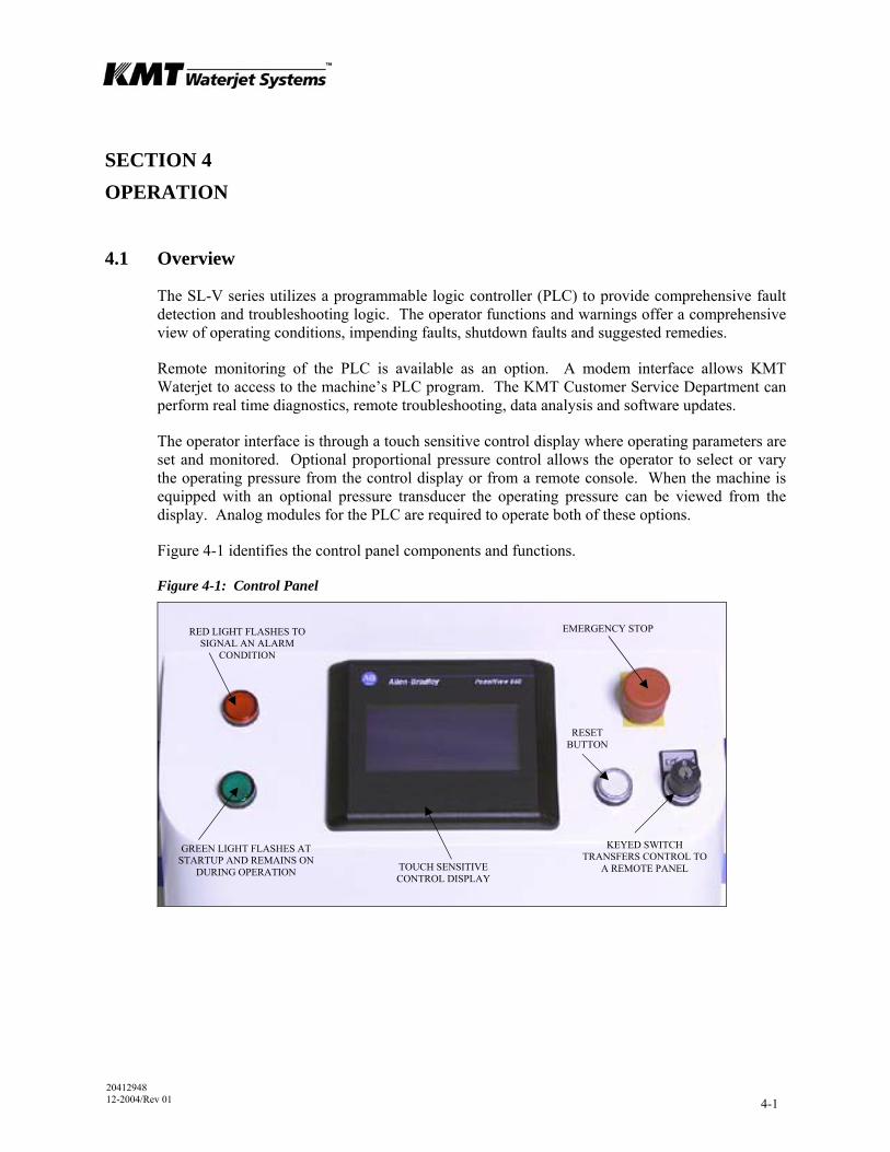
Figure 4-1 identifies the control panel components and functions.
Figure 4-1: Control Panel
RED LIGHT FLASHES TO SIGNAL AN ALARM
CONDITION
RESET BUTTON
KEYED SWITCH TRANSFERS CONTROL TO
A REMOTE PANEL
EMERGENCY STOP
GREEN LIGHT FLASHES AT STARTUP AND REMAINS ON
DURING OPERATION TOUCH SENSITIVE CONTROL DISPLAY
Section 4 Operation
20412948 12-2004/Rev 01 4-2
4.2 Startup Sequence
The startup sequence varies depending on the previous stop condition, and whether the machine is equipped with the optional pressure transducer.
Startup after Motor Stop After a normal motor stop the safety dump valve will be closed and high pressure will be present in the intensifier. Press the START button on the Run Screen to start the motor. The machine will be held in low pressure for 5-60 seconds as determined by the operator, it then goes to high pressure or remains in low pressure, depending on the previous pressure setting on the Run Screen.
If the machine is equipped with a pressure transducer and pressure is not allowed to bleed, the startup sequence is the same as above.
If the machine is equipped with a pressure transducer and pressure is allowed to bleed through the orifice to below 1,000 psi (69 bar), the dump valve will open. In this case, the startup sequence is as described below.
Startup after Emergency Stop After an emergency stop the safety dump valve will be open and high pressure released in the intensifier. The dump valve will close three seconds after the intensifier begins to stroke.
Pull the E-STOP button out and push the RESET button to activate the control display. Press the START button on the Run Screen to start the motor. The machine will be held in low pressure for for 5-60 seconds as determined by the operator, to allow trapped air to bleed from the high pressure cylinders. It then goes to high pressure or remains in low pressure, depending on the previous pressure setting on the Run Screen.
Section 4 Operation
20412948 12-2004/Rev 01 4-3
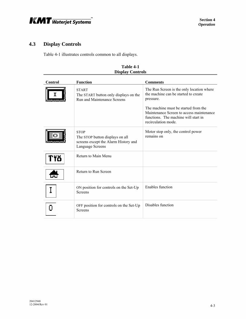
4.3 Display Controls
Table 4-1 illustrates controls common to all displays.
Table 4-1 Display Controls
Control Function Comments
START The START button only displays on the Run and Maintenance Screens
The Run Screen is the only location where the machine can be started to create pressure.
The machine must be started from the Maintenance Screen to access maintenance functions. The machine will start in recirculation mode.
STOP The STOP button displays on all screens except the Alarm History and Language Screens
Motor stop only, the control power remains on
Return to Main Menu
Return to Run Screen
ON position for controls on the Set-Up Screens
Enables function
OFF position for controls on the Set-Up Screens
Disables function
Section 4 Operation
20412948 12-2004/Rev 01 4-4
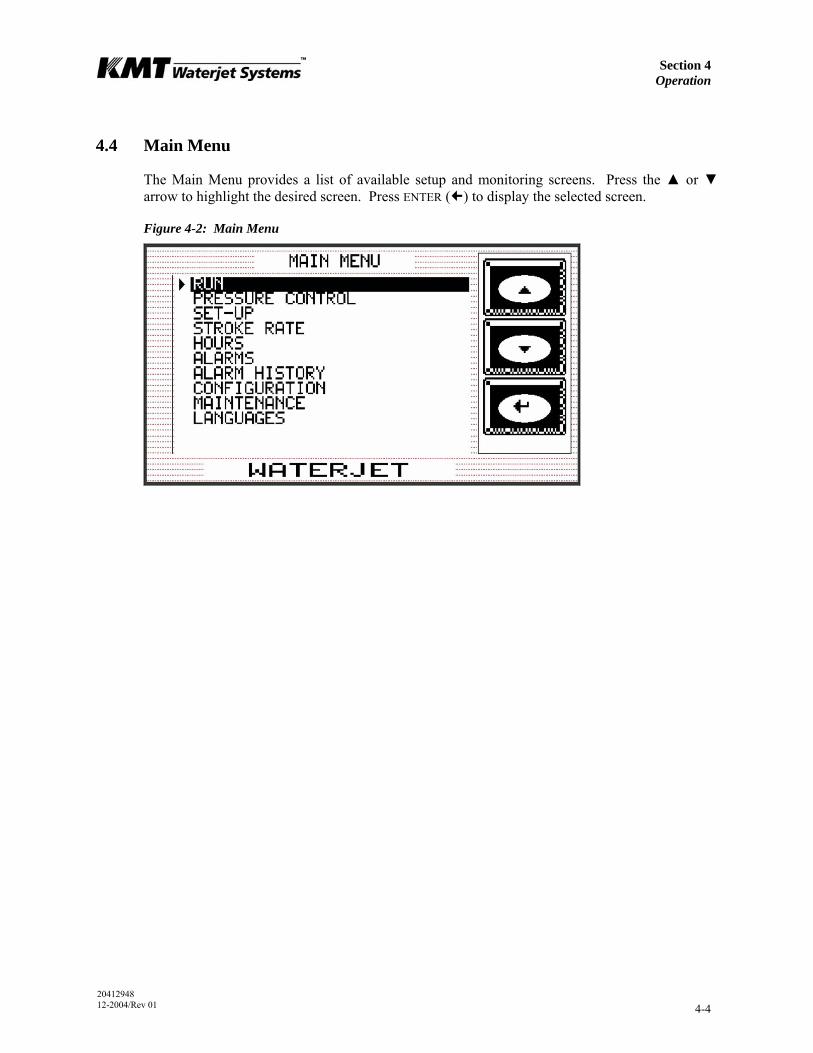
4.4 Main Menu
The Main Menu provides a list of available setup and monitoring screens. Press the ▲ or ▼ arrow to highlight the desired screen. Press ENTER ( ) to display the selected screen.
Figure 4-2: Main Menu
Section 4 Operation
20412948 12-2004/Rev 01 4-5
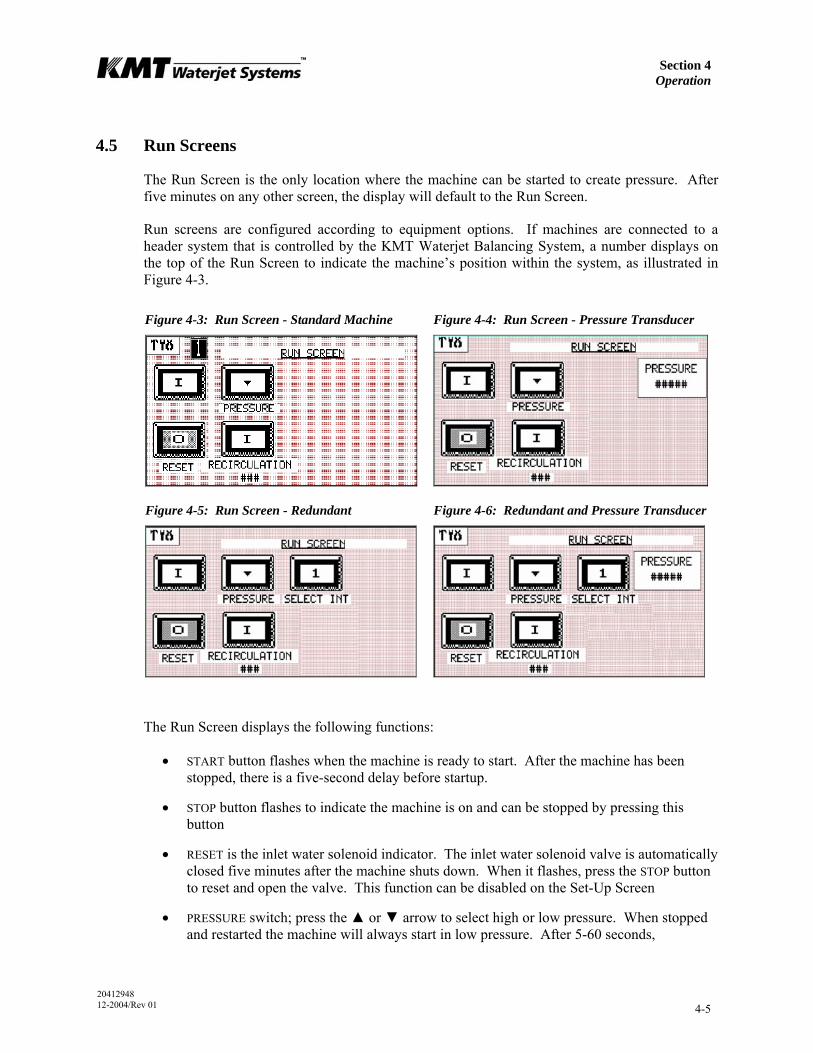
4.5 Run Screens
The Run Screen is the only location where the machine can be started to create pressure. After five minutes on any other screen, the display will default to the Run Screen.
Run screens are configured according to equipment options. If machines are connected to a header system that is controlled by the KMT Waterjet Balancing System, a number displays on the top of the Run Screen to indicate the machine’s position within the system, as illustrated in Figure 4-3.
Figure 4-3: Run Screen - Standard Machine Figure 4-4: Run Screen - Pressure Transducer
Figure 4-5: Run Screen - Redundant Figure 4-6: Redundant and Pressure Transducer
The Run Screen displays the following functions:
• START button flashes when the machine is ready to start. After the machine has been stopped, there is a five-second delay before startup.
• STOP button flashes to indicate the machine is on and can be stopped by pressing this button
• RESET is the inlet water solenoid indicator. The inlet water solenoid valve is automatically closed five minutes after the machine shuts down. When it flashes, press the STOP button to reset and open the valve. This function can be disabled on the Set-Up Screen
• PRESSURE switch; press the ▲ or ▼ arrow to select high or low pressure. When stopped and restarted the machine will always start in low pressure. After 5-60 seconds,
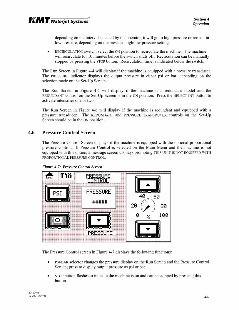
Section 4 Operation
20412948 12-2004/Rev 01 4-6
depending on the interval selected by the operator, it will go to high pressure or remain in low pressure, depending on the previous high/low pressure setting.
• RECIRCULATION switch; select the ON position to recirculate the machine. The machine will recirculate for 10 minutes before the switch shuts off. Recirculation can be manually stopped by pressing the STOP button. Recirculation time is indicated below the switch.
The Run Screen in Figure 4-4 will display if the machine is equipped with a pressure transducer. The PRESSURE indicator displays the output pressure in either psi or bar, depending on the selection made on the Set-Up Screen.
The Run Screen in Figure 4-5 will display if the machine is a redundant model and the REDUNDANT control on the Set-Up Screen is in the ON position. Press the SELECT INT button to activate intensifier one or two.
The Run Screen in Figure 4-6 will display if the machine is redundant and equipped with a pressure transducer. The REDUNDANT and PRESSURE TRANSDUCER controls on the Set-Up Screen should be in the ON position.
4.6 Pressure Control Screen
The Pressure Control Screen displays if the machine is equipped with the optional proportional pressure control. If Pressure Control is selected on the Main Menu and the machine is not equipped with this option, a message screen displays prompting THIS UNIT IS NOT EQUIPPED WITH PROPORTIONAL PRESSURE CONTROL.
Figure 4-7: Pressure Control Screen
The Pressure Control screen in Figure 4-7 displays the following functions:
• PSI/BAR selector changes the pressure display on the Run Screen and the Pressure Control Screen; press to display output pressure as psi or bar
• STOP button flashes to indicate the machine is on and can be stopped by pressing this button
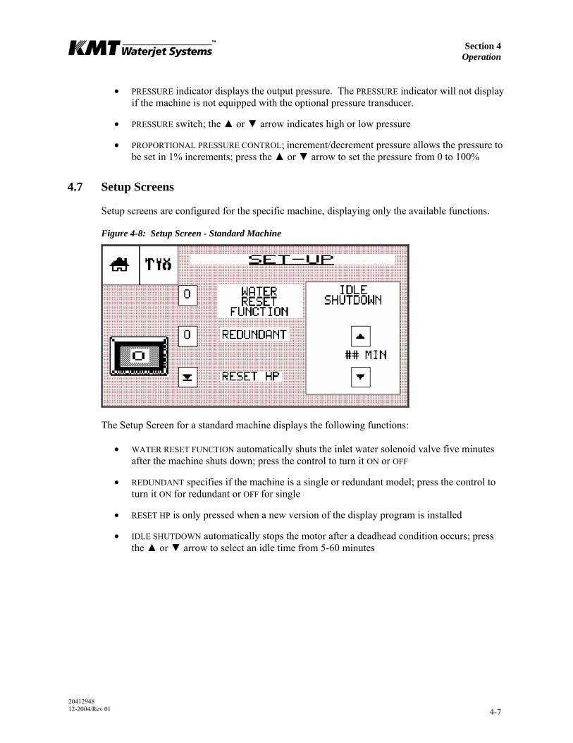
Section 4 Operation
20412948 12-2004/Rev 01 4-7
• PRESSURE indicator displays the output pressure. The PRESSURE indicator will not display if the machine is not equipped with the optional pressure transducer.
• PRESSURE switch; the ▲ or ▼ arrow indicates high or low pressure
• PROPORTIONAL PRESSURE CONTROL; increment/decrement pressure allows the pressure to be set in 1% increments; press the ▲ or ▼ arrow to set the pressure from 0 to 100%
4.7 Setup Screens
Setup screens are configured for the specific machine, displaying only the available functions.
Figure 4-8: Setup Screen - Standard Machine
The Setup Screen for a standard machine displays the following functions:
• WATER RESET FUNCTION automatically shuts the inlet water solenoid valve five minutes after the machine shuts down; press the control to turn it ON or OFF
• REDUNDANT specifies if the machine is a single or redundant model; press the control to turn it ON for redundant or OFF for single
• RESET HP is only pressed when a new version of the display program is installed
• IDLE SHUTDOWN automatically stops the motor after a deadhead condition occurs; press the ▲ or ▼ arrow to select an idle time from 5-60 minutes
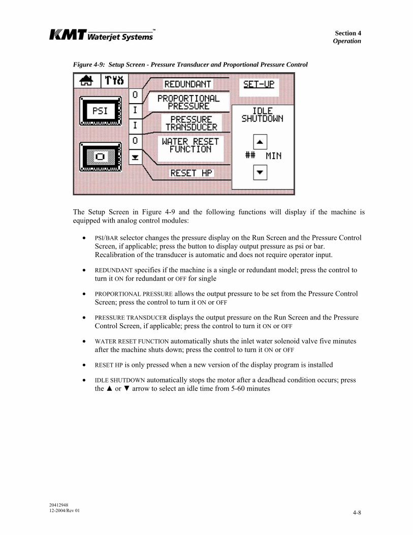
Section 4 Operation
20412948 12-2004/Rev 01 4-8
Figure 4-9: Setup Screen - Pressure Transducer and Proportional Pressure Control
The Setup Screen in Figure 4-9 and the following functions will display if the machine is equipped with analog control modules:
• PSI/BAR selector changes the pressure display on the Run Screen and the Pressure Control Screen, if applicable; press the button to display output pressure as psi or bar. Recalibration of the transducer is automatic and does not require operator input.
• REDUNDANT specifies if the machine is a single or redundant model; press the control to turn it ON for redundant or OFF for single
• PROPORTIONAL PRESSURE allows the output pressure to be set from the Pressure Control Screen; press the control to turn it ON or OFF
• PRESSURE TRANSDUCER displays the output pressure on the Run Screen and the Pressure Control Screen, if applicable; press the control to turn it ON or OFF
• WATER RESET FUNCTION automatically shuts the inlet water solenoid valve five minutes after the machine shuts down; press the control to turn it ON or OFF
• RESET HP is only pressed when a new version of the display program is installed
• IDLE SHUTDOWN automatically stops the motor after a deadhead condition occurs; press the ▲ or ▼ arrow to select an idle time from 5-60 minutes
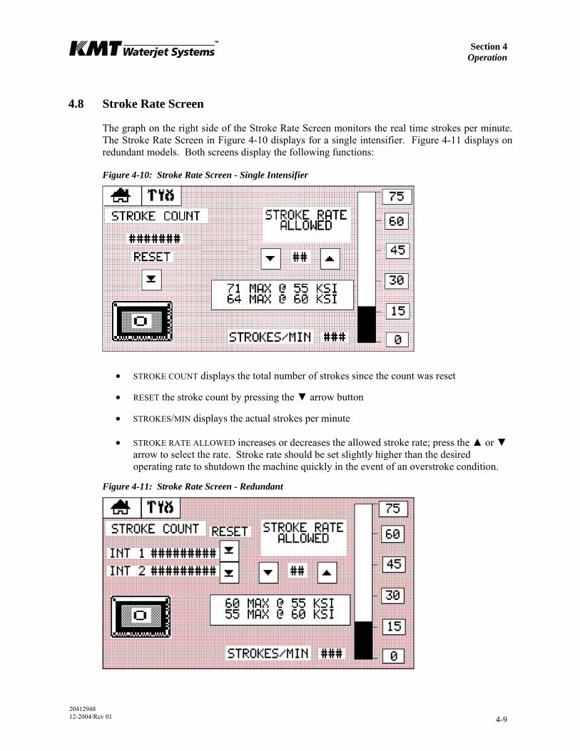
Section 4 Operation
20412948 12-2004/Rev 01 4-9
4.8 Stroke Rate Screen
The graph on the right side of the Stroke Rate Screen monitors the real time strokes per minute. The Stroke Rate Screen in Figure 4-10 displays for a single intensifier. Figure 4-11 displays on redundant models. Both screens display the following functions:
Figure 4-10: Stroke Rate Screen - Single Intensifier
• STROKE COUNT displays the total number of strokes since the count was reset
• RESET the stroke count by pressing the ▼ arrow button
• STROKES/MIN displays the actual strokes per minute
• STROKE RATE ALLOWED increases or decreases the allowed stroke rate; press the ▲ or ▼ arrow to select the rate. Stroke rate should be set slightly higher than the desired operating rate to shutdown the machine quickly in the event of an overstroke condition.
Figure 4-11: Stroke Rate Screen - Redundant
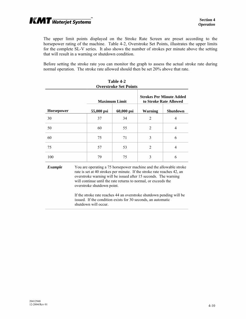
Section 4 Operation
20412948 12-2004/Rev 01 4-10
The upper limit points displayed on the Stroke Rate Screen are preset according to the horsepower rating of the machine. Table 4-2, Overstroke Set Points, illustrates the upper limits for the complete SL-V series. It also shows the number of strokes per minute above the setting that will result in a warning or shutdown condition.
Before setting the stroke rate you can monitor the graph to assess the actual stroke rate during normal operation. The stroke rate allowed should then be set 20% above that rate.
Table 4-2 Overstroke Set Points
Maximum Limit
Strokes Per Minute Added to Stroke Rate Allowed
Horsepower 55,000 psi 60,000 psi Warning Shutdown
30 37 34 2 4
50 60 55 2 4
60 75 71 3 6
75 57 53 2 4
100 79 75 3 6
Example You are operating a 75 horsepower machine and the allowable stroke rate is set at 40 strokes per minute. If the stroke rate reaches 42, an overstroke warning will be issued after 15 seconds. The warning will continue until the rate returns to normal, or exceeds the overstroke shutdown point.
If the stroke rate reaches 44 an overstroke shutdown pending will be issued. If the condition exists for 30 seconds, an automatic shutdown will occur.
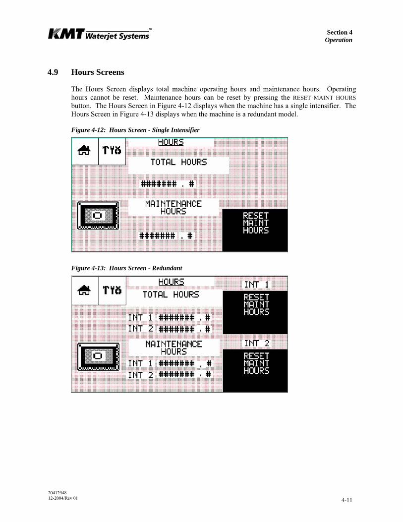
Section 4 Operation
20412948 12-2004/Rev 01 4-11
4.9 Hours Screens
The Hours Screen displays total machine operating hours and maintenance hours. Operating hours cannot be reset. Maintenance hours can be reset by pressing the RESET MAINT HOURS button. The Hours Screen in Figure 4-12 displays when the machine has a single intensifier. The Hours Screen in Figure 4-13 displays when the machine is a redundant model.
Figure 4-12: Hours Screen - Single Intensifier
Figure 4-13: Hours Screen - Redundant

Section 4 Operation
20412948 12-2004/Rev 01 4-12
4.10 Run Screen Alarms
In an alarm state, the last alarm sensed by the machine will be displayed on the Run Screen. If multiple alarm conditions have occurred they can be viewed on the Alarms Screen. Run Screen alarms are listed in Table 4-3.
Figure 4-14: Run Screen Alarm
Table 4-3 Run Screen Alarms
Alarm Indication Comments
Bleed High Pressure Lines
Intensifier is shut down, high pressure is present in the discharge plumbing and should be bled off to avoid possible injury
Applies only when equipped with optional pressure transducer
Booster Temperature High
Booster pump water temperature is high, in excess of 128° F (53° C).
Shutdown will occur if condition persists.
High Oil Temperature
High hydraulic oil temperature, in excess of 144° F (62° C)
Shutdown will occur if condition persists.
High Pressure Warning
Output pressure is above 64,000 psi (4,413 bar)
Applies only when equipped with optional pressure transducer

Section 4 Operation
20412948 12-2004/Rev 01 4-13
Table 4-3 Run Screen Alarms
Alarm Indication Comments
Left/Right/Intensifier Overstroke
Abnormally high stroke rate caused by an external or internal leak. Shutdown will occur if condition persists.
Overstroke warnings, pending shutdowns and shutdowns are issued as left, right or intensifier. An intensifier warning or shutdown indicates the intensifier is shifting too fast in both directions. If the machine is running near full capacity it is possible an intensifier shutdown is actually caused by a left or right fault. This can be diagnosed further by reducing the operating pressure and monitoring all alarm occurrences on the Alarms Screen.
If the machine is equipped with a pressure transducer, another level of overstroke protection is obtained by shutting down at the warning level if the pressure is less than 3,000 psi (207 bar).
Low Battery Battery is low. After the alarm occurs, the battery will last for approximately seven days.
Replace with backup/replacement battery.
Low Booster Pressure
Booster pump output pressure is inadequate for proper machine operation, less than 60 psi (4 bar). Shutdown is pending.
Seven seconds after the machine is started, the booster pump output pressure switch is monitored. If the switch opens, a warning is issued. If the condition persists, shutdown will occur after 30 seconds.
Low Inlet Water Pressure
Cutting supply water pressure is inadequate to permit proper machine operation, less than 30 psi (2 bar).
If the inlet cutting watering pressure switch is not closed the machine will not start and a warning is issued. If the switch opens after the machine is started a warning is issued. If the condition persists shutdown occurs after five consecutive seconds.
Reset Inlet Water Inlet water solenoid valve must be reset. RESET will flash and can be reset by pressing the STOP button
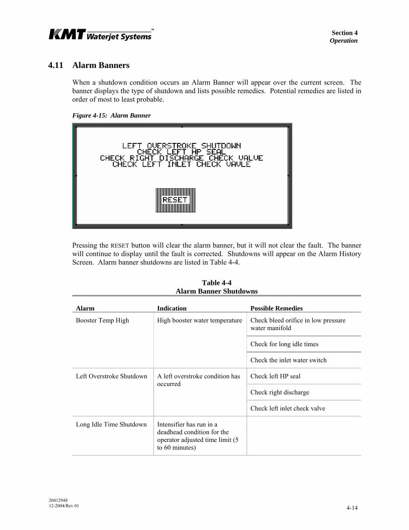
Section 4 Operation
20412948 12-2004/Rev 01 4-14
4.11 Alarm Banners
When a shutdown condition occurs an Alarm Banner will appear over the current screen. The banner displays the type of shutdown and lists possible remedies. Potential remedies are listed in order of most to least probable.
Figure 4-15: Alarm Banner
Pressing the RESET button will clear the alarm banner, but it will not clear the fault. The banner will continue to display until the fault is corrected. Shutdowns will appear on the Alarm History Screen. Alarm banner shutdowns are listed in Table 4-4.
Table 4-4 Alarm Banner Shutdowns
Alarm Indication Possible Remedies
Check bleed orifice in low pressure water manifold
Check for long idle times
Booster Temp High High booster water temperature
Check the inlet water switch
Check left HP seal
Check right discharge
Left Overstroke Shutdown A left overstroke condition has occurred
Check left inlet check valve
Long Idle Time Shutdown Intensifier has run in a deadhead condition for the operator adjusted time limit (5 to 60 minutes)
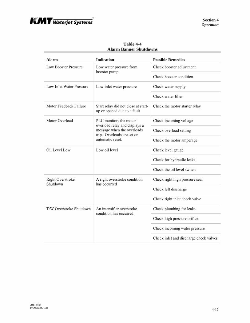
Section 4 Operation
20412948 12-2004/Rev 01 4-15
Table 4-4 Alarm Banner Shutdowns
Alarm Indication Possible Remedies
Check booster adjustment Low Booster Pressure Low water pressure from booster pump
Check booster condition
Check water supply Low Inlet Water Pressure Low inlet water pressure
Check water filter
Motor Feedback Failure Start relay did not close at start-up or opened due to a fault
Check the motor starter relay
Check incoming voltage
Check overload setting
Motor Overload PLC monitors the motor overload relay and displays a message when the overloads trip. Overloads are set on automatic reset. Check the motor amperage
Check level gauge
Check for hydraulic leaks
Oil Level Low Low oil level
Check the oil level switch
Check right high pressure seal
Check left discharge
Right Overstroke Shutdown
A right overstroke condition has occurred
Check right inlet check valve
Check plumbing for leaks
Check high pressure orifice
Check incoming water pressure
T/W Overstroke Shutdown An intensifier overstroke condition has occurred
Check inlet and discharge check valves
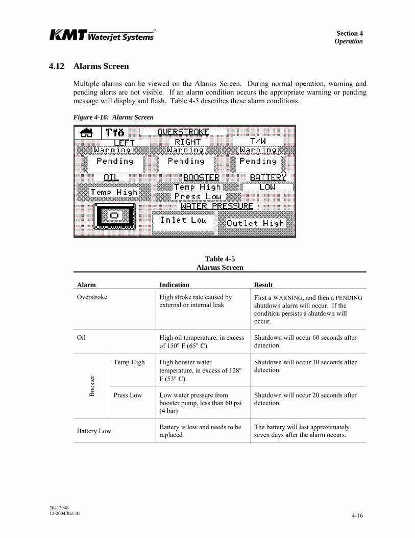
Section 4 Operation
20412948 12-2004/Rev 01 4-16
4.12 Alarms Screen
Multiple alarms can be viewed on the Alarms Screen. During normal operation, warning and pending alerts are not visible. If an alarm condition occurs the appropriate warning or pending message will display and flash. Table 4-5 describes these alarm conditions.
Figure 4-16: Alarms Screen
Table 4-5 Alarms Screen
Alarm Indication Result
Overstroke High stroke rate caused by external or internal leak
First a WARNING, and then a PENDING shutdown alarm will occur. If the condition persists a shutdown will occur.
Oil High oil temperature, in excess of 150° F (65° C)
Shutdown will occur 60 seconds after detection.
Temp High High booster water temperature, in excess of 128° F (53° C)
Shutdown will occur 30 seconds after detection.
Boo
ster
Press Low Low water pressure from booster pump, less than 60 psi (4 bar)
Shutdown will occur 20 seconds after detection.
Battery Low Battery is low and needs to be replaced
The battery will last approximately seven days after the alarm occurs.
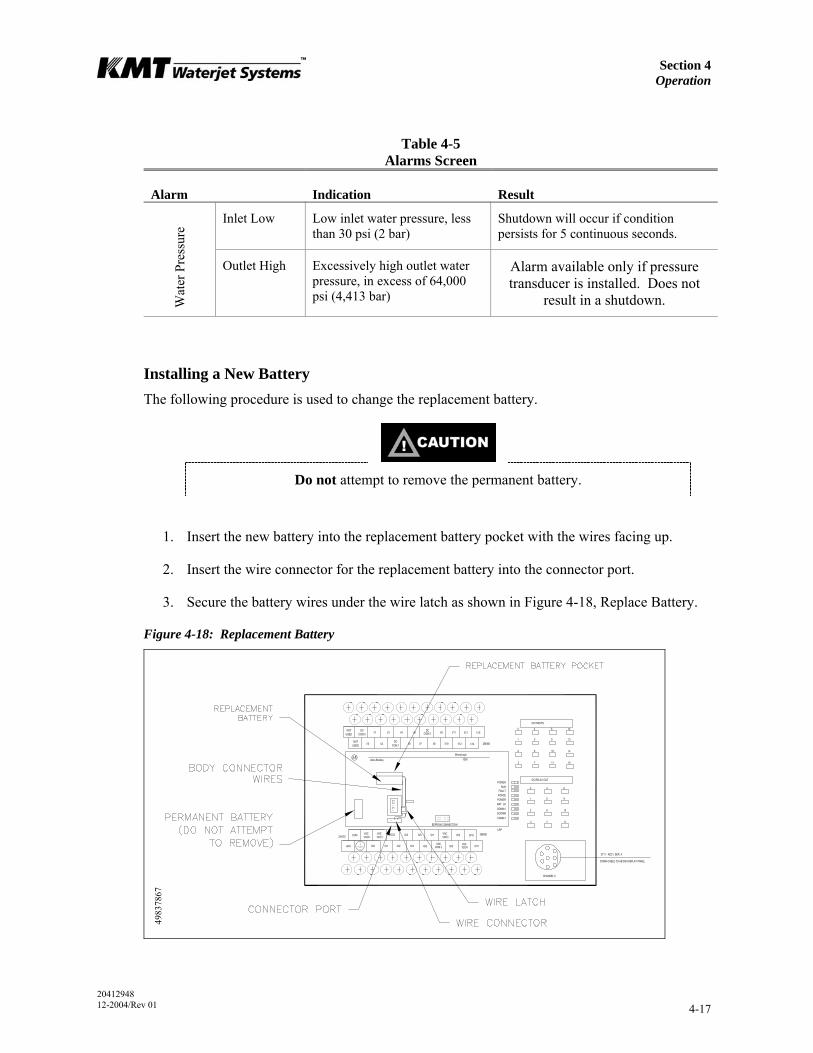
Section 4 Operation
20412948 12-2004/Rev 01 4-17
Table 4-5 Alarms Screen
Alarm Indication Result
Inlet Low Low inlet water pressure, less than 30 psi (2 bar)
Shutdown will occur if condition persists for 5 continuous seconds.
Wat
er P
ress
ure
Outlet High Excessively high outlet water pressure, in excess of 64,000 psi (4,413 bar)
Alarm available only if pressure transducer is installed. Does not
result in a shutdown.
Installing a New Battery The following procedure is used to change the replacement battery.
Do not attempt to remove the permanent battery.
1. Insert the new battery into the replacement battery pocket with the wires facing up.
2. Insert the wire connector for the replacement battery into the connector port.
3. Secure the battery wires under the wire latch as shown in Figure 4-18, Replace Battery.
Figure 4-18: Replacement Battery
4983
7867
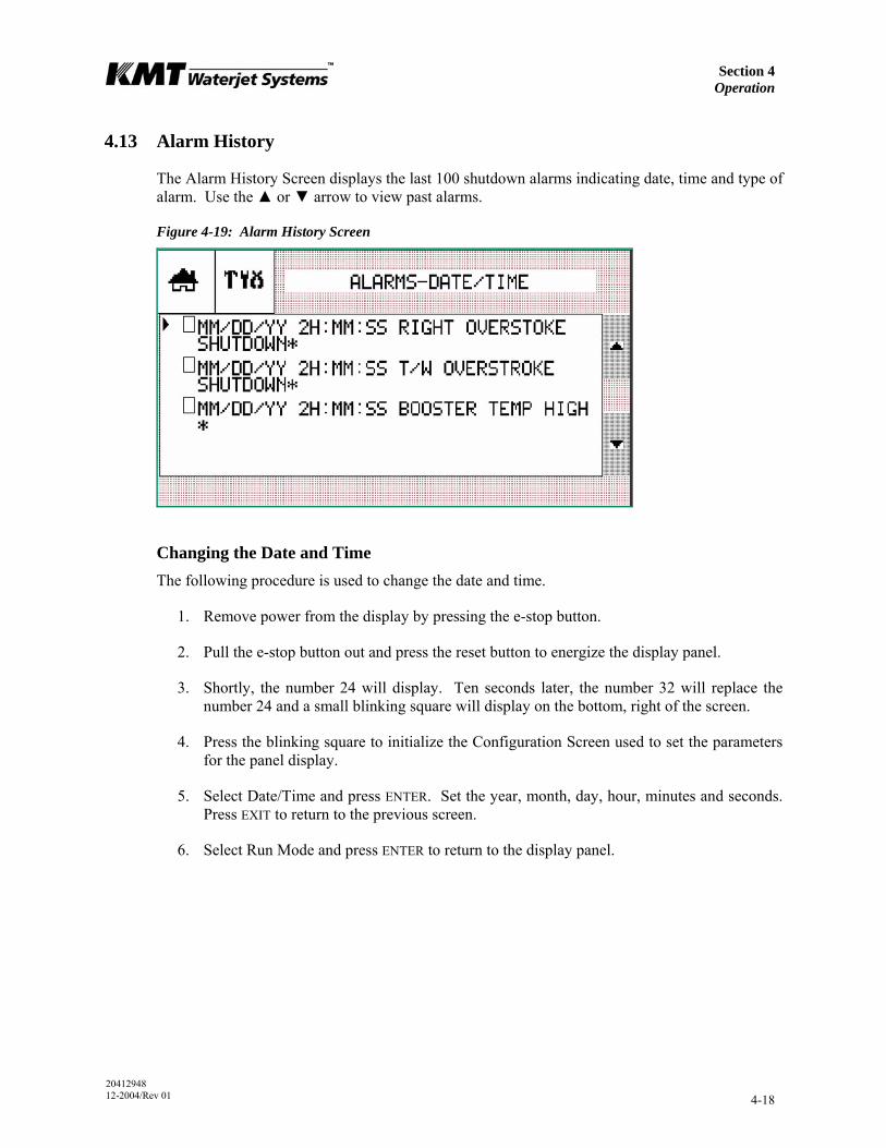
Section 4 Operation
20412948 12-2004/Rev 01 4-18
4.13 Alarm History
The Alarm History Screen displays the last 100 shutdown alarms indicating date, time and type of alarm. Use the ▲ or ▼ arrow to view past alarms.
Figure 4-19: Alarm History Screen
Changing the Date and Time The following procedure is used to change the date and time.
1. Remove power from the display by pressing the e-stop button.
2. Pull the e-stop button out and press the reset button to energize the display panel.
3. Shortly, the number 24 will display. Ten seconds later, the number 32 will replace the number 24 and a small blinking square will display on the bottom, right of the screen.
4. Press the blinking square to initialize the Configuration Screen used to set the parameters for the panel display.
5. Select Date/Time and press ENTER. Set the year, month, day, hour, minutes and seconds. Press EXIT to return to the previous screen.
6. Select Run Mode and press ENTER to return to the display panel.

Section 4 Operation
20412948 12-2004/Rev 01 4-19
4.14 Configuration Screen
The Configuration Screen is a password protected screen, used only at initial start up to set the horsepower. If a new version of the display program is installed you must press the RESET HP button on the Setup Screen to update the displays.
4.15 Maintenance Screen
The Maintenance Screen is used to facilitate maintenance procedures and provides the PLC and display logic part number and revision number. When started from the Maintenance Screen, the machine starts in recirculation mode.
Figure 4-20: Maintenance Screen
The machine must be started from the Maintenance Screen to access the following functions:
• START button will start the machine in recirculation mode and open the dump valve
• STOP button will stop the machine
• RESET is the inlet water solenoid indicator. The inlet water solenoid valve is automatically closed five minutes after the machine shuts down. When it flashes, press the STOP button to reset and open the valve.
• STARTUP PRESSURE TIMER; press the ▲ or ▼ arrow to select a startup time from 5-60 seconds. This will determine the startup time between low and high pressure operation.
• RIGHT arrow will open the dump valve and extend the piston to the right, allowing full exposure to the right plunger when the unit is disassembled. The unit must be completely assembled to use this jog function.
• LEFT arrow will open the dump valve and extend the piston to the left, allowing full exposure to the left plunger when the unit is disassembled. The unit must be completely assembled to use this jog function.

Section 4 Operation
20412948 12-2004/Rev 01 4-20
• CENTER symbol will open the dump valve and position the piston in the center of the hydraulic cylinder. To center the piston, first press the RIGHT arrow to extend the plunger to the right, then press the CENTER symbol to center the piston. The unit must be completely assembled to use this jog function.
4.16 Language Screen
The Language Screen lists the available display languages. Press the ▲ or ▼ arrow to highlight the desired language. Press ENTER ( ) to select.
Figure 4-21: Language Screen

20412955 1-2006/Rev 03 5-1
SECTION 5 LOW PRESSURE WATER SYSTEM
5.1 Overview
The SL-V series utilizes two low pressure circuits: cutting water supply and cooling water supply. This section will discuss the cutting water supply circuit. See Section 6, Recirculation System, for a detailed explanation of the cooling water supply circuit.
The cutting water supply circuit supplies the intensifier with the required cutting water flow and pressure. System components include the inlet water solenoid valve, strainer, booster pump, and the low pressure filter assembly. Pressure and temperature switches, connected to the PLC, monitor out of tolerance conditions in the cutting water circuit and provide automatic shutdown protection.
Figure 5-1: Cutting Water Supply Circuit
TO BOOSTER PRESSURE GAUGE
TO CUTTING WATER SUPPLY GAUGE
CUTTING WATER IN
DRAIN
FILTER ASSEMBLY
RELIEF VALVE
BOOSTER PUMP
60 PSI PRESSURE
SWITCH
30 PSI PRESSURE
SWITCH TEMPERATURE
SWITCH
AIR BLEED VALVE
SEALING HEADS
RELIEF VALVE
CHECK VALVE
ORIFICE
INLET WATER SOLENOID VALVE
4983
5622
STRAINER
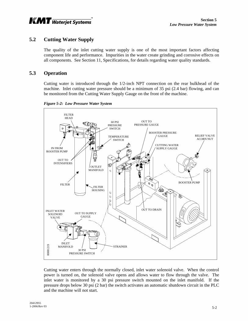
Section 5 Low Pressure Water System
20412955 1-2006/Rev 03 5-2
5.2 Cutting Water Supply
The quality of the inlet cutting water supply is one of the most important factors affecting component life and performance. Impurities in the water create grinding and corrosive effects on all components. See Section 11, Specifications, for details regarding water quality standards.
5.3 Operation
Cutting water is introduced through the 1/2-inch NPT connection on the rear bulkhead of the machine. Inlet cutting water pressure should be a minimum of 35 psi (2.4 bar) flowing, and can be monitored from the Cutting Water Supply Gauge on the front of the machine.
Figure 5-2: Low Pressure Water System
Cutting water enters through the normally closed, inlet water solenoid valve. When the control power is turned on, the solenoid valve opens and allows water to flow through the valve. The inlet water is monitored by a 30 psi pressure switch mounted on the inlet manifold. If the pressure drops below 30 psi (2 bar) the switch activates an automatic shutdown circuit in the PLC and the machine will not start.
INLET WATER SOLENOID
VALVE
FILTER HEAD
BOOSTER PUMPFILTER
HOUSING
FILTER
60 PSI PRESSURE
SWITCHBOOSTER PRESSURE
GAUGE
CUTTING WATER SUPPLY GAUGE
RELIEF VALVE ACORN NUT
30 PSI PRESSURE SWITCH
TEMPERATURE SWITCH
OUT TO INTENSIFIERS
OUT TO SUPPLY GAUGE
OUT TO PRESSURE GAUGE
OUT TO DRAIN
IN FROM BOOSTER PUMP
8008
1219
STRAINER INLET
MANIFOLD
OUTLET MANIFOLD
Section 5 Low Pressure Water System
20412955 1-2006/Rev 03 5-3
NOTE
The machine will not start if inlet cutting water pressure is below 30 psi (2 bar).
If a shutdown occurs due to an overstroke condition, the inlet solenoid valve automatically closes to prevent water waste due to an external leak. Additionally, the valve automatically closes at the idle shutdown interval selected by the operator.
Cutting water then passes through a strainer to remove debris before the water enters the booster pump. The booster pump increases the pressure to the relief valve setting, up to a maximum of 120 psi (8 bar) to ensure proper supply to the intensifier assembly.
Pressurized water passes through the filter assembly where debris is removed to prevent contaminants from damaging the check valves and seals in the intensifier. The filter assembly consists of a filter head, housing and a 10 micron absolute filter. A bleed valve on the top of the filter head is used to release pressure or air inside the housing.
As the water enters the outlet manifold, the discharge pressure is monitored by a 60 psi pressure switch. An automatic shutdown will occur if the pressure is below 60 psi (4 bar).
If the booster pump pressure exceeds 125 psi (8.6 bar) a relief valve opens allowing water to exit through the 1/2-inch drain connection on the rear bulkhead. It is still possible to operate the machine; however, excess water will continue to be released through the drain.
Discharge pressure is displayed on the Booster Pressure Gauge on the front of the machine. The gauge should read approximately 120 psi (8 bar) while the machine is idling. When it strokes, the pressure drop should be no greater than 30 psi (2 bar). The water pressure range should remain between 90-120 psi (6-8 bar) during operation.
NOTE
While the intensifier assembly reverses direction, the boosted pressure will fluctuate slightly above and below the normal setting.
A relief valve built into the booster pump prevents excessive discharge pressure and typically operates when the machine is in a deadhead condition. The booster pump is factory set to deliver 120 psi (8 bar) with an inlet pressure of 58 psi (4 bar). The pump may require adjustment to satisfy system requirements.
A temperature switch, mounted on the outlet manifold, monitors the discharge temperature. If the temperature exceeds 128° F (53° C), the switch activates an automatic shutdown circuit in the PLC that stops the main motor. The temperature switch prevents booster pump overheating due to lack of water or long deadhead conditions. To reduce overheating during a deadhead condition, water is re-circulated through the orifice and check valve, and routed back through the strainer to the booster pump inlet.
Section 5 Low Pressure Water System
20412955 1-2006/Rev 03 5-4
From the outlet manifold, cutting water is routed to the inlet check valves in the sealing heads on each end of the intensifier. If the machine is equipped with redundant intensifiers, the cutting water supply lines are manually connected to the active intensifier and manual hydraulic valves are opened or closed to direct the hydraulic flow to the active intensifier. Control is switched from one intensifier to the other from the control panel.
If the machine is equipped with dual intensifiers, cutting water and hydraulic fluid are routed to both intensifiers.
5.4 Operating Specifications
Table 5-1 lists the operating specifications for the low pressure cutting water supply system.
Table 5-1 Operating Specifications
Low Pressure Cutting Water Supply System
30 HP 50 HP 60 HP 75 HP 100 HP 100D
Maximum consumption gpm (L/min)
2.5 (9.5) 4.0 (15.1) 4.5 (17.0) 6.0 (22.7) 8.0 (30.0) 8.0 (30.0)
Minimum inlet water pressure 35 psi (2.4 bar) flowing
Maximum inlet water pressure 100 psi (6.9 bar)
Maximum outlet water pressure 120 psi (8.3 bar)
Booster pump factory set inlet pressure 58 psi (4 bar)
Booster pump factory set outlet pressure 120 psi (8.3 bar)
Optimum inlet water temperature 65° F (18° C)
Low inlet water pressure 30 psi (2 bar)
Low booster pressure 60 psi (4 bar)
Booster pump overheat 128° F (53° C)
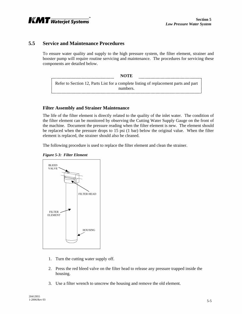
Section 5 Low Pressure Water System
20412955 1-2006/Rev 03 5-5
5.5 Service and Maintenance Procedures
To ensure water quality and supply to the high pressure system, the filter element, strainer and booster pump will require routine servicing and maintenance. The procedures for servicing these components are detailed below.
NOTE
Refer to Section 12, Parts List for a complete listing of replacement parts and part numbers.
Filter Assembly and Strainer Maintenance The life of the filter element is directly related to the quality of the inlet water. The condition of the filter element can be monitored by observing the Cutting Water Supply Gauge on the front of the machine. Document the pressure reading when the filter element is new. The element should be replaced when the pressure drops to 15 psi (1 bar) below the original value. When the filter element is replaced, the strainer should also be cleaned.
The following procedure is used to replace the filter element and clean the strainer.
Figure 5-3: Filter Element
1. Turn the cutting water supply off.
2. Press the red bleed valve on the filter head to release any pressure trapped inside the housing.
3. Use a filter wrench to unscrew the housing and remove the old element.
FILTER ELEMENT
HOUSING
FILTER HEAD
BLEED VALVE
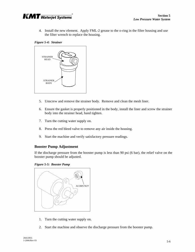
Section 5 Low Pressure Water System
20412955 1-2006/Rev 03 5-6
4. Install the new element. Apply FML-2 grease to the o-ring in the filter housing and use the filter wrench to replace the housing.
Figure 5-4: Strainer
5. Unscrew and remove the strainer body. Remove and clean the mesh liner.
6. Ensure the gasket is properly positioned in the body, install the liner and screw the strainer body into the strainer head, hand tighten.
7. Turn the cutting water supply on.
8. Press the red bleed valve to remove any air inside the housing.
9. Start the machine and verify satisfactory pressure readings.
Booster Pump Adjustment If the discharge pressure from the booster pump is less than 90 psi (6 bar), the relief valve on the booster pump should be adjusted.
Figure 5-5: Booster Pump
1. Turn the cutting water supply on.
2. Start the machine and observe the discharge pressure from the booster pump.
ACORN NUT
STRAINER HEAD
STRAINER BODY

Section 5 Low Pressure Water System
20412955 1-2006/Rev 03 5-7
3. Remove the acorn nut on the side of the pump to access the adjustment screw. It is normal for water to leak out when the acorn nut is removed.
4. Use a flat screwdriver and turn the adjustment screw clockwise to increase the discharge pressure or counter-clockwise to decrease the pressure. Adjust the pressure to the highest desired pressure, within normal booster pump range.
If the adjustment screw is turned too far out (counter-clockwise) an internal spring and relief will fall down inside the pump. If this occurs, the pump must be
removed and the parts must be reinstalled to avoid component damage.
5. Replace the acorn nut and resume normal operation.
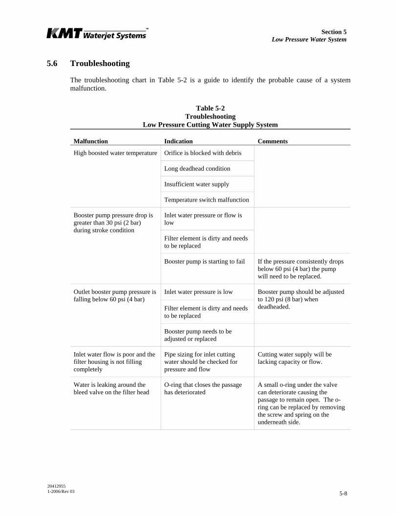
Section 5 Low Pressure Water System
20412955 1-2006/Rev 03 5-8
5.6 Troubleshooting
The troubleshooting chart in Table 5-2 is a guide to identify the probable cause of a system malfunction.
Table 5-2 Troubleshooting
Low Pressure Cutting Water Supply System
Malfunction Indication Comments
Orifice is blocked with debris
Long deadhead condition
Insufficient water supply
High boosted water temperature
Temperature switch malfunction
Inlet water pressure or flow is low
Filter element is dirty and needs to be replaced
Booster pump pressure drop is greater than 30 psi (2 bar) during stroke condition
Booster pump is starting to fail If the pressure consistently drops below 60 psi (4 bar) the pump will need to be replaced.
Inlet water pressure is low
Filter element is dirty and needs to be replaced
Booster pump should be adjusted to 120 psi (8 bar) when deadheaded.
Outlet booster pump pressure is falling below 60 psi (4 bar)
Booster pump needs to be adjusted or replaced
Inlet water flow is poor and the filter housing is not filling completely
Pipe sizing for inlet cutting water should be checked for pressure and flow
Cutting water supply will be lacking capacity or flow.
Water is leaking around the bleed valve on the filter head
O-ring that closes the passage has deteriorated
A small o-ring under the valve can deteriorate causing the passage to remain open. The o-ring can be replaced by removing the screw and spring on the underneath side.
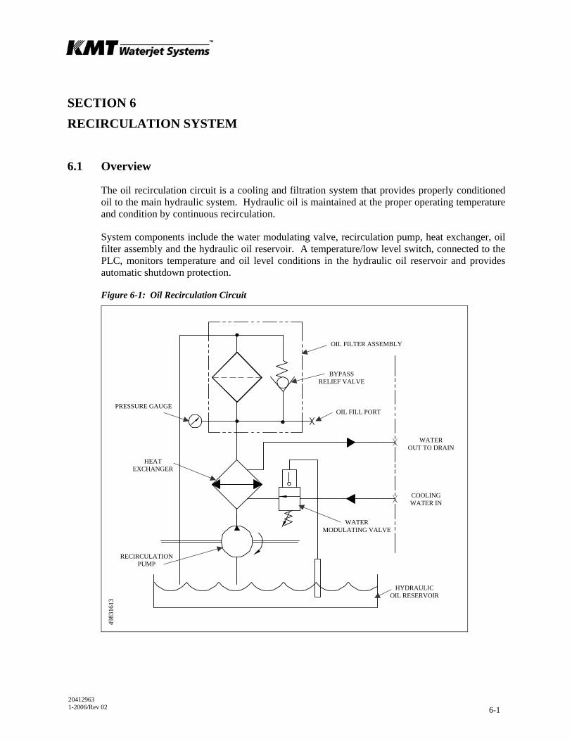
20412963 1-2006/Rev 02 6-1
SECTION 6 RECIRCULATION SYSTEM
6.1 Overview
The oil recirculation circuit is a cooling and filtration system that provides properly conditioned oil to the main hydraulic system. Hydraulic oil is maintained at the proper operating temperature and condition by continuous recirculation.
System components include the water modulating valve, recirculation pump, heat exchanger, oil filter assembly and the hydraulic oil reservoir. A temperature/low level switch, connected to the PLC, monitors temperature and oil level conditions in the hydraulic oil reservoir and provides automatic shutdown protection.
Figure 6-1: Oil Recirculation Circuit
BYPASS RELIEF VALVE
OIL FILL PORT
OIL FILTER ASSEMBLY
PRESSURE GAUGE
HEAT EXCHANGER
WATER MODULATING VALVE
HYDRAULIC OIL RESERVOIR
RECIRCULATION PUMP
WATER OUT TO DRAIN
COOLING WATER IN
4983
1613

Section 6 Recirculation System
20412963 1-2006/Rev 02 6-2
6.2 Operation
Cooling water is introduced through the 1/2-inch NPT connection on the rear bulkhead of the machine where the water modulating valve regulates the cooling flow to the heat exchanger. The valve is factory set, but may require adjustment to maintain the operating oil temperature at 115° F (46° C). Oil temperature can be visually monitored from a dual scale level/temperature sight gauge on the side of the hydraulic oil reservoir.
Figure 6-2: Recirculation System Components
The recirculation pump pulls oil from the reservoir and sends it to the heat exchanger. The oil-to-water heat exchanger controls heat build-up in the hydraulic oil. The plate style design allows cooling water and oil to flow side by side through alternating plates.
The cooled oil then passes through the filter element and returns to the reservoir. The cooling water either is discharged to the 1/2-inch NPT drain on the rear bulkhead or is routed to a customer supplied water chiller.
The hydraulic oil filter assembly consists of the filter head, a filter element, pressure gauge or indicator, bypass relief valve and the oil fill port. All 30 and 50 horsepower machines are equipped with a numeric pressure gauge that indicates inlet pressure. The filter element should be changed when the gauge reads 40 psi (2.8 bar) at normal operating temperature. The 60, 75
RECIRCULATION PUMP
CASE DRAIN WATER MODULATING VALVE
OIL FILL PORT
PRESSURE GAUGE/INDICATOR
FILTER HEAD
HYDRAULIC OIL RESERVOIR
HEAT EXCHANGER
FILTER ELEMENT
TEMPERATURE/LOW LEVEL SWITCH
AIR BREATHER
LEVEL/TEMPERATURE SIGHT GAUGE
8008
1250

Section 6 Recirculation System
20412963 1-2006/Rev 02 6-3
and 100 horsepower machines utilize a differential pressure indicator. The filter element on these machines should be changed when the indicator enters the red zone at normal operating temperature.
If the element is not replaced, and fills with debris, the bypass relief in the filter head will open to prevent over pressurization. The relief valve opens at 50 psi (3.4 bar) on 30 and 50 horsepower models, 25 psi (1.7 bar) on 60, 75 and 100 horsepower models. When the valve opens, the oil bypasses the filter and unfiltered oil is allowed to return to the reservoir.
The temperature/low level switch monitors the oil temperature and level in the reservoir. An automatic shutdown will occur if the operating oil temperature exceeds 144° F (62° C). An automatic shutdown will also occur if the oil level on a 30 or 50 horsepower machine falls below 21 gal (80 L). Low oil level shutdown occurs at 37 gal (140 L) on a 60, 75 or 100 horsepower machine.
NOTE
To conserve water usage it is recommended that the cooling water be shut off at the end of the day. A sensor bulb from the modulating valve is submerged in the
reservoir. Even when the control power is off, the valve will remain open, allowing water to flow until the oil is cooled.
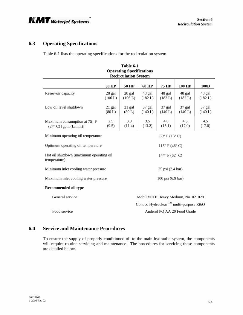
Section 6 Recirculation System
20412963 1-2006/Rev 02 6-4
6.3 Operating Specifications
Table 6-1 lists the operating specifications for the recirculation system.
Table 6-1 Operating Specifications
Recirculation System
30 HP 50 HP 60 HP 75 HP 100 HP 100D
Reservoir capacity 28 gal (106 L)
28 gal (106 L)
48 gal (182 L)
48 gal (182 L)
48 gal (182 L)
48 gal (182 L)
Low oil level shutdown 21 gal (80 L)
21 gal (80 L)
37 gal (140 L)
37 gal (140 L)
37 gal (140 L)
37 gal (140 L)
Maximum consumption at 75° F (24° C) [gpm (L/min)]
2.5 (9.5)
3.0 (11.4)
3.5 (13.2)
4.0 (15.1)
4.5 (17.0)
4.5 (17.0)
Minimum operating oil temperature 60° F (15° C)
Optimum operating oil temperature 115° F (46° C)
Hot oil shutdown (maximum operating oil temperature)
144° F (62° C)
Minimum inlet cooling water pressure 35 psi (2.4 bar)
Maximum inlet cooling water pressure 100 psi (6.9 bar)
Recommended oil type
General service Mobil #DTE Heavy Medium, No. 021029
Conoco Hydroclear TM multi-purpose R&O
Food service Anderol PQ AA 20 Food Grade
6.4 Service and Maintenance Procedures
To ensure the supply of properly conditioned oil to the main hydraulic system, the components will require routine servicing and maintenance. The procedures for servicing these components are detailed below.
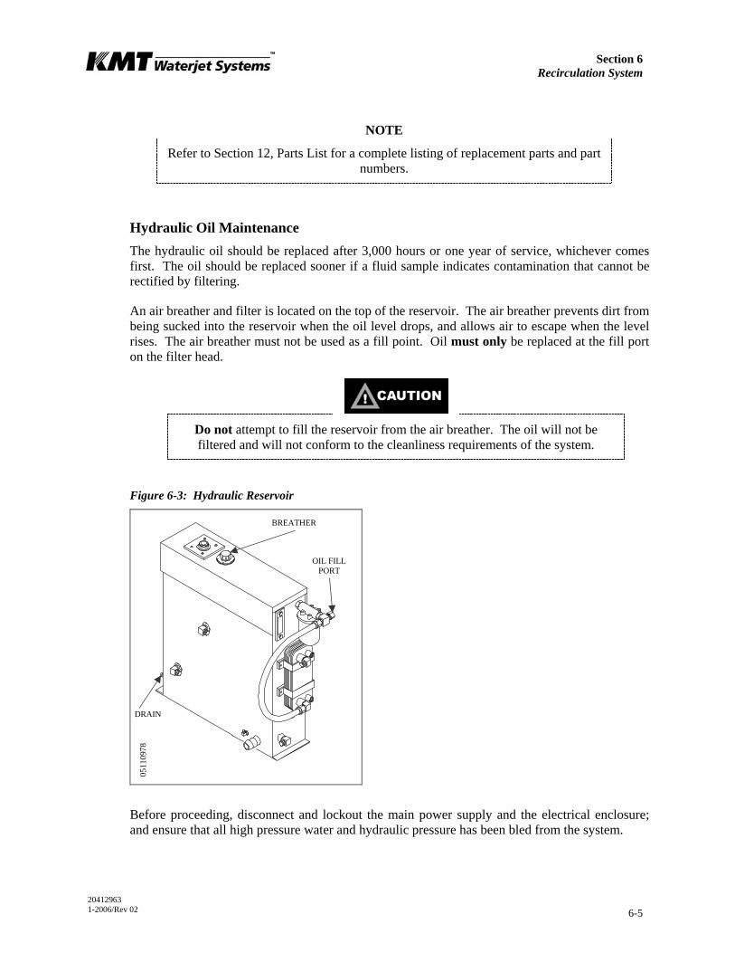
Section 6 Recirculation System
20412963 1-2006/Rev 02 6-5
NOTE
Refer to Section 12, Parts List for a complete listing of replacement parts and part numbers.
Hydraulic Oil Maintenance The hydraulic oil should be replaced after 3,000 hours or one year of service, whichever comes first. The oil should be replaced sooner if a fluid sample indicates contamination that cannot be rectified by filtering.
An air breather and filter is located on the top of the reservoir. The air breather prevents dirt from being sucked into the reservoir when the oil level drops, and allows air to escape when the level rises. The air breather must not be used as a fill point. Oil must only be replaced at the fill port on the filter head.
Do not attempt to fill the reservoir from the air breather. The oil will not be filtered and will not conform to the cleanliness requirements of the system.
Figure 6-3: Hydraulic Reservoir
Before proceeding, disconnect and lockout the main power supply and the electrical enclosure; and ensure that all high pressure water and hydraulic pressure has been bled from the system.
0511
0978
OIL FILL PORT
DRAIN
BREATHER

Section 6 Recirculation System
20412963 1-2006/Rev 02 6-6
Severe injury can result if the machine is not properly locked out. Observe electrical Lockout/Tagout procedures before performing maintenance.
Ensure all pressure is relieved or blocked from the hydraulic and high pressure circuits before performing maintenance.
1. Drain the oil reservoir by connecting the inlet hose from an oil transfer pump to the drain valve on the reservoir.
2. Open the shut off valve on the drain and pump the used oil out to a container.
3. Close the shut off valve and remove the inlet hose from the drain valve.
NOTE
Oil from a new drum does not meet the cleanliness requirements of the hydraulic system. For this reason, it is important to use an oil transfer pump that will force
oil through the return filter into the reservoir.
4. Remove the cap from the fill port on the oil filter.
To ensure cleanliness, the oil fill port must be used to pump oil into the reservoir. Filling at this point guarantees the hydraulic oil will pass through the oil filter
before entering the reservoir.
5. Connect the discharge hose from the oil transfer pump to the fill port and pump the fresh oil into the reservoir.
NOTE
If 3/4-inch BSPP threads are required, install the adapter located on the inside of the frame. When filling is complete, remove the adapter and install the fill port
cap.
6. Check the oil sight gauge on the reservoir to ensure proper fill level.
7. Remove the hose from the case drain on the main hydraulic pump to make sure the pump case fills with oil. With the hose removed, head pressure from the reservoir will force oil into the pump case.

Section 6 Recirculation System
20412963 1-2006/Rev 02 6-7
Oil in the pump case provides internal lubrication for the main hydraulic pump. Failure to the fill the pump case with oil will allow air to become trapped inside,
damaging the pump.
8. Disconnect the discharge hose from the fill port and replace the fill port cap.
9. Follow the initial start up sequence in Section 4, Operation, to ensure the system is filled with oil.
10. Check the sight gauge again and follow the same procedure to add additional oil if necessary.
Oil Filter Maintenance If the filter element is not properly serviced and fills with debris, the oil will be forced through the relief valve, bypassing the filter. The bypass relief valve on 30 and 50 horsepower models opens at 50 psi (3.4 bar), it opens at 25 psi (1.7 bar) on 60, 75 and 100 horsepower models. The filter element must be replaced when the pressure gauge or indicator meets the criteria listed in Table 6-2.
Table 6-2 Hydraulic Oil Filter Change Criteria
Horsepower Indicator Criteria
30 50 Numeric pressure gauge
Replace filter element when the pressure reading is 40 psi (2.8 bar) or greater during normal operating conditions.
60 75
100 Differential pressure indicator
Replace filter element when the indicator is in the yellow zone or entering the red zone during normal operating conditions.
Note Normal operating conditions indicate the machine is running and the oil temperature has reached 115° F (46° C).
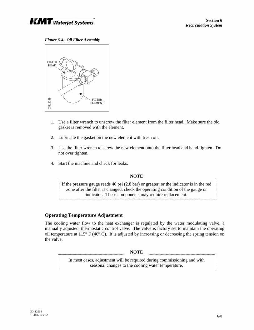
Section 6 Recirculation System
20412963 1-2006/Rev 02 6-8
Figure 6-4: Oil Filter Assembly
1. Use a filter wrench to unscrew the filter element from the filter head. Make sure the old gasket is removed with the element.
2. Lubricate the gasket on the new element with fresh oil.
3. Use the filter wrench to screw the new element onto the filter head and hand-tighten. Do not over tighten.
4. Start the machine and check for leaks.
NOTE
If the pressure gauge reads 40 psi (2.8 bar) or greater, or the indicator is in the red zone after the filter is changed, check the operating condition of the gauge or
indicator. These components may require replacement.
Operating Temperature Adjustment The cooling water flow to the heat exchanger is regulated by the water modulating valve, a manually adjusted, thermostatic control valve. The valve is factory set to maintain the operating oil temperature at 115° F (46° C). It is adjusted by increasing or decreasing the spring tension on the valve.
NOTE
In most cases, adjustment will be required during commissioning and with seasonal changes to the cooling water temperature.
0511
8229
FILTER HEAD
FILTER ELEMENT
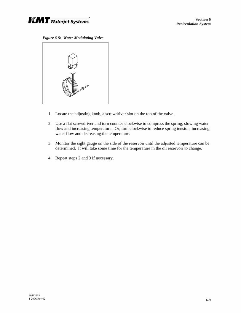
Section 6 Recirculation System
20412963 1-2006/Rev 02 6-9
Figure 6-5: Water Modulating Valve
1. Locate the adjusting knob, a screwdriver slot on the top of the valve.
2. Use a flat screwdriver and turn counter-clockwise to compress the spring, slowing water flow and increasing temperature. Or; turn clockwise to reduce spring tension, increasing water flow and decreasing the temperature.
3. Monitor the sight gauge on the side of the reservoir until the adjusted temperature can be determined. It will take some time for the temperature in the oil reservoir to change.
4. Repeat steps 2 and 3 if necessary.
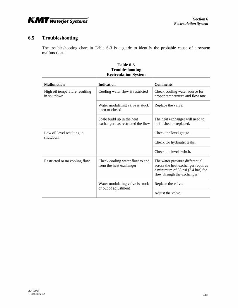
Section 6 Recirculation System
20412963 1-2006/Rev 02 6-10
6.5 Troubleshooting
The troubleshooting chart in Table 6-3 is a guide to identify the probable cause of a system malfunction.
Table 6-3 Troubleshooting
Recirculation System
Malfunction Indication Comments
Cooling water flow is restricted Check cooling water source for proper temperature and flow rate.
Water modulating valve is stuck open or closed
Replace the valve.
High oil temperature resulting in shutdown
Scale build up in the heat exchanger has restricted the flow
The heat exchanger will need to be flushed or replaced.
Check the level gauge.
Check for hydraulic leaks.
Low oil level resulting in shutdown
Check the level switch.
Restricted or no cooling flow Check cooling water flow to and from the heat exchanger
The water pressure differential across the heat exchanger requires a minimum of 35 psi (2.4 bar) for flow through the exchanger.
Replace the valve. Water modulating valve is stuck or out of adjustment
Adjust the valve.
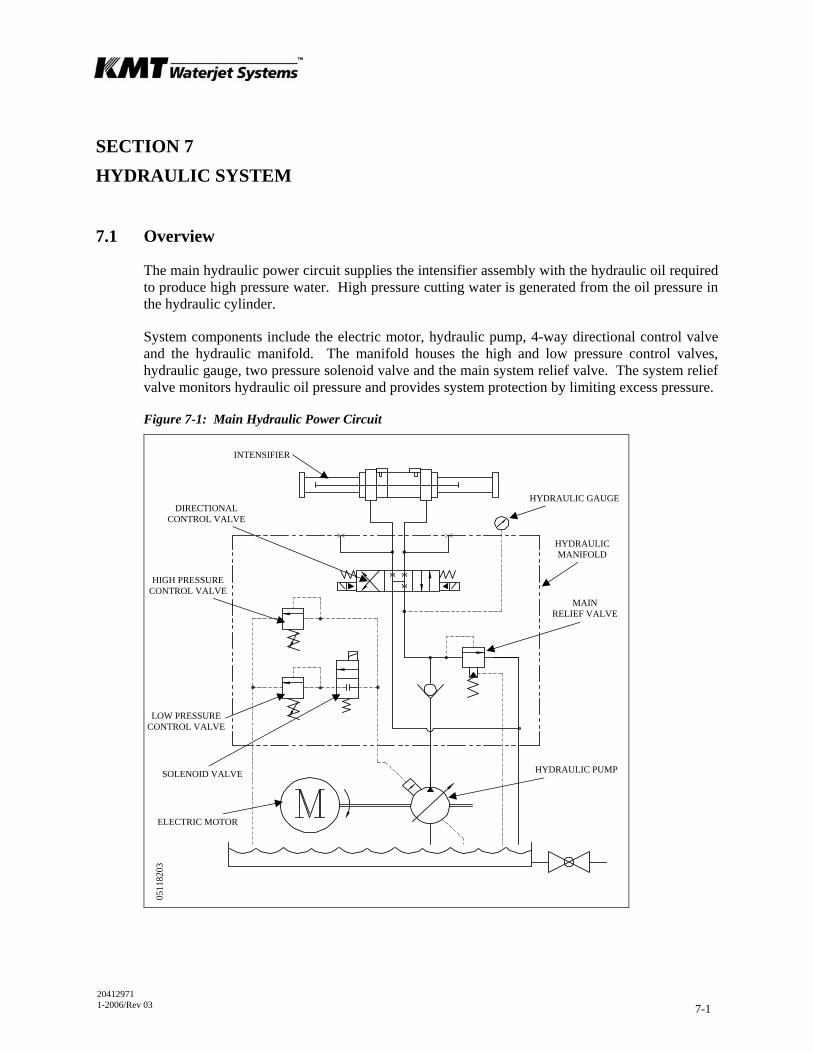
20412971 1-2006/Rev 03 7-1
SECTION 7 HYDRAULIC SYSTEM
7.1 Overview
The main hydraulic power circuit supplies the intensifier assembly with the hydraulic oil required to produce high pressure water. High pressure cutting water is generated from the oil pressure in the hydraulic cylinder.
System components include the electric motor, hydraulic pump, 4-way directional control valve and the hydraulic manifold. The manifold houses the high and low pressure control valves, hydraulic gauge, two pressure solenoid valve and the main system relief valve. The system relief valve monitors hydraulic oil pressure and provides system protection by limiting excess pressure.
Figure 7-1: Main Hydraulic Power Circuit
HYDRAULIC GAUGE
HYDRAULIC MANIFOLD
MAIN RELIEF VALVE
INTENSIFIER
HYDRAULIC PUMP SOLENOID VALVE
LOW PRESSURE CONTROL VALVE
HIGH PRESSURE CONTROL VALVE
DIRECTIONAL CONTROL VALVE
ELECTRIC MOTOR
0511
8203
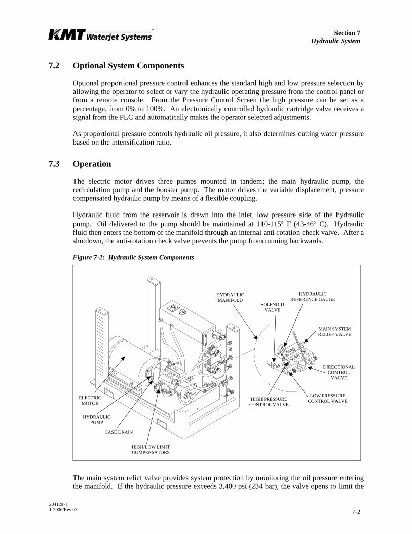
Section 7 Hydraulic System
20412971 1-2006/Rev 03 7-2
7.2 Optional System Components
Optional proportional pressure control enhances the standard high and low pressure selection by allowing the operator to select or vary the hydraulic operating pressure from the control panel or from a remote console. From the Pressure Control Screen the high pressure can be set as a percentage, from 0% to 100%. An electronically controlled hydraulic cartridge valve receives a signal from the PLC and automatically makes the operator selected adjustments.
As proportional pressure controls hydraulic oil pressure, it also determines cutting water pressure based on the intensification ratio.
7.3 Operation
The electric motor drives three pumps mounted in tandem; the main hydraulic pump, the recirculation pump and the booster pump. The motor drives the variable displacement, pressure compensated hydraulic pump by means of a flexible coupling.
Hydraulic fluid from the reservoir is drawn into the inlet, low pressure side of the hydraulic pump. Oil delivered to the pump should be maintained at 110-115° F (43-46° C). Hydraulic fluid then enters the bottom of the manifold through an internal anti-rotation check valve. After a shutdown, the anti-rotation check valve prevents the pump from running backwards.
Figure 7-2: Hydraulic System Components
The main system relief valve provides system protection by monitoring the oil pressure entering the manifold. If the hydraulic pressure exceeds 3,400 psi (234 bar), the valve opens to limit the
ELECTRIC MOTOR
HYDRAULIC PUMP
MAIN SYSTEM RELIEF VALVE
CASE DRAIN
HIGH/LOW LIMIT COMPENSATORS
HIGH PRESSURE CONTROL VALVE
LOW PRESSURE CONTROL VALVE
HYDRAULIC REFERENCE GAUGE
DIRECTIONAL CONTROL
VALVE
HYDRAULIC MANIFOLD
SOLENOID VALVE
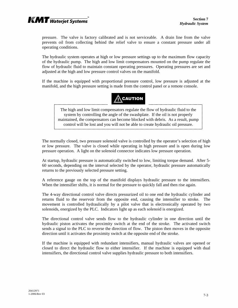
Section 7 Hydraulic System
20412971 1-2006/Rev 03 7-3
pressure. The valve is factory calibrated and is not serviceable. A drain line from the valve prevents oil from collecting behind the relief valve to ensure a constant pressure under all operating conditions.
The hydraulic system operates at high or low pressure settings up to the maximum flow capacity of the hydraulic pump. The high and low limit compensators mounted on the pump regulate the flow of hydraulic fluid to maintain constant operating pressures. Operating pressures are set and adjusted at the high and low pressure control valves on the manifold.
If the machine is equipped with proportional pressure control, low pressure is adjusted at the manifold, and the high pressure setting is made from the control panel or a remote console.
The high and low limit compensators regulate the flow of hydraulic fluid to the system by controlling the angle of the swashplate. If the oil is not properly
maintained, the compensators can become blocked with debris. As a result, pump control will be lost and you will not be able to create hydraulic oil pressure.
The normally closed, two pressure solenoid valve is controlled by the operator’s selection of high or low pressure. The valve is closed while operating in high pressure and is open during low pressure operation. A light on the solenoid connector indicates low pressure operation.
At startup, hydraulic pressure is automatically switched to low, limiting torque demand. After 5-60 seconds, depending on the interval selected by the operator, hydraulic pressure automatically returns to the previously selected pressure setting.
A reference gauge on the top of the manifold displays hydraulic pressure to the intensifiers. When the intensifier shifts, it is normal for the pressure to quickly fall and then rise again.
The 4-way directional control valve directs pressurized oil to one end the hydraulic cylinder and returns fluid to the reservoir from the opposite end, causing the intensifier to stroke. The movement is controlled hydraulically by a pilot valve that is electronically operated by two solenoids, energized by the PLC. Indicators light up as each solenoid is energized.
The directional control valve sends flow to the hydraulic cylinder in one direction until the hydraulic piston activates the proximity switch at the end of the stroke. The activated switch sends a signal to the PLC to reverse the direction of flow. The piston then moves in the opposite direction until it activates the proximity switch at the opposite end of the stroke.
If the machine is equipped with redundant intensifiers, manual hydraulic valves are opened or closed to direct the hydraulic flow to either intensifier. If the machine is equipped with dual intensifiers, the directional control valve supplies hydraulic pressure to both intensifiers.

Section 7 Hydraulic System
20412971 1-2006/Rev 03 7-4
7.4 Operating Specifications
Table 7-1 lists the operating specifications for the hydraulic system.
Table 7-1 Operating Specifications
Hydraulic System
Main system relief valve 3,400 psi (234 bar)
Maximum operating pressure 3,000 psi (207 bar)
7.5 Service and Maintenance Procedures
The extreme duty cycles demanded of the hydraulic system make routine inspection and maintenance acutely important. Leaks must be detected and remedied as soon as possible.
The operating pressure settings must be checked daily, and the electric motor must be inspected at regular intervals. It is also possible for the flexible coupling to fail and require replacement. The procedures for servicing these components are detailed below.
NOTE
Refer to Section 12, Parts List for a complete listing of replacement parts and part numbers.
Hydraulic Operating Pressure
Hydraulic operating pressure settings should be checked daily and adjusted as necessary. High and low operating pressure on standard machines is adjusted at the high and low pressure control valves per the specifications in Table 7-2.
For machines equipped with proportional pressure control, high pressure adjustments are made from the Pressure Control Screen on the control panel. The following specifications and the Low Pressure Adjustment procedure are used for low pressure adjustments.
NOTE
The PRESSURE switch on the control panel must be set to high pressure to enable the PROPORTIONAL PRESSURE control.
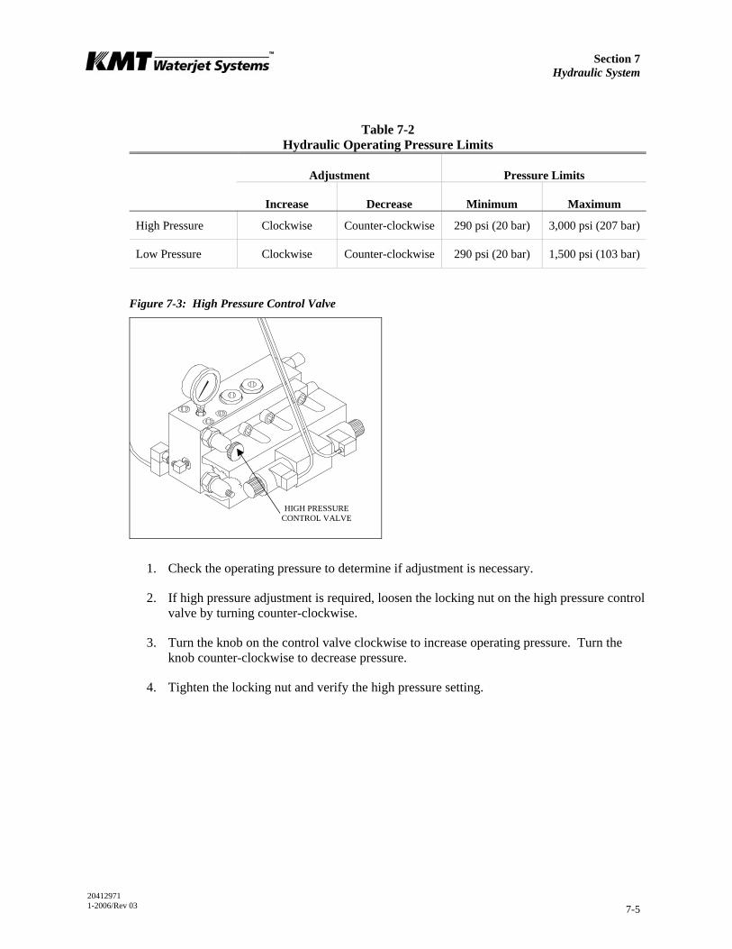
Section 7 Hydraulic System
20412971 1-2006/Rev 03 7-5
Table 7-2 Hydraulic Operating Pressure Limits
Adjustment Pressure Limits
Increase Decrease Minimum Maximum
High Pressure Clockwise Counter-clockwise 290 psi (20 bar) 3,000 psi (207 bar)
Low Pressure Clockwise Counter-clockwise 290 psi (20 bar) 1,500 psi (103 bar)
Figure 7-3: High Pressure Control Valve
1. Check the operating pressure to determine if adjustment is necessary.
2. If high pressure adjustment is required, loosen the locking nut on the high pressure control valve by turning counter-clockwise.
3. Turn the knob on the control valve clockwise to increase operating pressure. Turn the knob counter-clockwise to decrease pressure.
4. Tighten the locking nut and verify the high pressure setting.
HIGH PRESSURE CONTROL VALVE

Section 7 Hydraulic System
20412971 1-2006/Rev 03 7-6
Figure 7-4: Low Pressure Control Valve
1. Check the operating pressure to determine if adjustment is necessary.
2. If low pressure adjustment is required, loosen the locking nut on the low pressure control valve by turning counter-clockwise.
3. Turn the hex clockwise to increase operating pressure. Turn the hex counter-clockwise to decrease pressure.
4. Tighten the locking nut and verify the low pressure setting.
LOW PRESSURE CONTROL VALVE
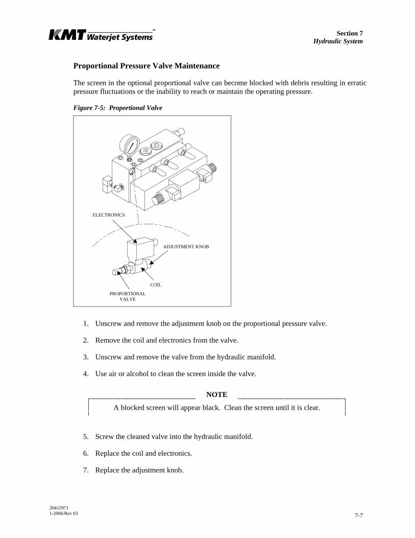
Section 7 Hydraulic System
20412971 1-2006/Rev 03 7-7
Proportional Pressure Valve Maintenance
The screen in the optional proportional valve can become blocked with debris resulting in erratic pressure fluctuations or the inability to reach or maintain the operating pressure.
Figure 7-5: Proportional Valve
1. Unscrew and remove the adjustment knob on the proportional pressure valve.
2. Remove the coil and electronics from the valve.
3. Unscrew and remove the valve from the hydraulic manifold.
4. Use air or alcohol to clean the screen inside the valve.
NOTE
A blocked screen will appear black. Clean the screen until it is clear.
5. Screw the cleaned valve into the hydraulic manifold.
6. Replace the coil and electronics.
7. Replace the adjustment knob.
ELECTRONICS
COIL
ADJUSTMENT KNOB
PROPORTIONAL VALVE

Section 7 Hydraulic System
20412971 1-2006/Rev 03 7-8
Motor Maintenance
The motor should be inspected at regular intervals, approximately every 500 hours of operation or every three months, whichever occurs first. Keep the motor clean and the ventilation openings clear.
Flexible Coupling Replacement
When the flexible coupling fails, the pump shaft will not turn and pressure will not be created. Typically, failure will be sudden, without any warning signs.
The electric motor and hydraulic pump are mounted in tandem on all SL-V models. Although the configuration is the same, the motor, pump, mountings, connections and components vary slightly according to horsepower. The procedure for replacing the flexible coupling is the same for all models.
Figure 7-6: Flexible Coupling Replacement
Severe injury can result if the machine is not properly locked out. Observe electrical Lockout/Tagout procedures before performing maintenance on the
system components.
Ensure all pressure is relieved or blocked from the hydraulic and high pressure circuits before performing maintenance.
VIBRATION ISOLATION MOUNT
COUPLING HALF
FLEXIBLE COUPLING
MOTOR COUPLING HALF
FLANGE

Section 7 Hydraulic System
20412971 1-2006/Rev 03 7-9
1. Remove the bolts attaching the motor vibration mounts to the frame base plate.
2. Use wooden blocks to support the hydraulic pump and manifold assembly. Leave all hose connections intact.
NOTE
A forklift can also be used by trained, experienced personnel to support the pump and manifold assembly.
3. Remove the bolts attaching the hydraulic pump to the electric motor.
4. Slide the motor away from the pump and manifold assembly to expose the flexible coupling.
NOTE
If additional clearance is required to separate the motor and pump, the electrical panel can be removed from the end of the frame. Remove the hex nuts from the
studs holding the electrical panel. Move the panel 4-8 inches away from the frame.
It should not be necessary to disconnect the motor lead wires. However, the wire ties holding the electrical control harness to the top pan will need to be removed in
order to move the electrical panel.
5. Remove the failed flexible coupling.
6. Wipe any residue, dirt or oil from the coupling halves on both the motor shaft, and the pump shaft. Avoid damaging the shaft seal on the pump.
NOTE
Additional clearance and access to the motor and pump coupling can be achieved by moving the pump and manifold assembly to the right. The pump suction hose
will limit movement to approximately one inch. It should not be necessary to disconnect any hydraulic hoses.
7. Inspect the metal splines on the coupling halves for damage. If damage is detected, replace the coupling half.
8. Inspect the shaft cavity of the hydraulic pump for the presence of hydraulic oil or evidence of hydraulic leaks. If a hydraulic leak is detected, the shaft seal must be replaced.
9. Install the new flexible coupling over the coupling half on the motor shaft, aligning the splines, and push the flexible coupling on as far as it will go. The internal ring or snap ring keeps the coupling centered between the motor and pump shafts.
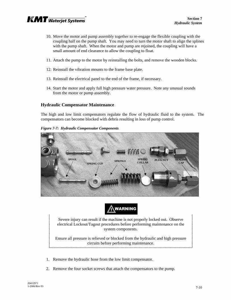
Section 7 Hydraulic System
20412971 1-2006/Rev 03 7-10
10. Move the motor and pump assembly together to re-engage the flexible coupling with the coupling half on the pump shaft. You may need to turn the motor shaft to align the splines with the pump shaft. When the motor and pump are rejoined, the coupling will have a small amount of end clearance to allow the coupling to float.
11. Attach the pump to the motor by reinstalling the bolts, and remove the wooden blocks.
12. Reinstall the vibration mounts to the frame base plate.
13. Reinstall the electrical panel to the end of the frame, if necessary.
14. Start the motor and apply full high pressure water pressure. Note any unusual sounds from the motor or pump assembly.
Hydraulic Compensator Maintenance
The high and low limit compensators regulate the flow of hydraulic fluid to the system. The compensators can become blocked with debris resulting in loss of pump control.
Figure 7-7: Hydraulic Compensator Components
Severe injury can result if the machine is not properly locked out. Observe electrical Lockout/Tagout procedures before performing maintenance on the
system components.
Ensure all pressure is relieved or blocked from the hydraulic and high pressure circuits before performing maintenance.
1. Remove the hydraulic hose from the low limit compensator.
2. Remove the four socket screws that attach the compensators to the pump.
SPOOL SPRING CUP
SPRINGS SPRING COLLAR
PLUG NUT SEALING CAP

Section 7 Hydraulic System
20412971 1-2006/Rev 03 7-11
3. Remove the compensators and then remove the three plugs and o-rings on the back of the housing.
4. Disassemble the compensators one at a time by first removing the hexagon sealing cap.
5. Loosen the lock nut, and then remove the plug nut.
6. Disassemble the plug by removing the spring collar, springs, spring cup and spool.
7. Clean the housing and all components with clean fluid and carefully dry with air.
8. Check and clean the small internal passages in the spools.
9. Check and clean the orifices in both spools.
10. Assemble in the reverse order, ensuring that the screw slot on the orifice is aligned with the long axis of the body.
When the compensators are removed, the machine loses adjustment. The compensators must be reset before operation can begin.
11. Start the machine and select the low pressure operating mode on the display panel.
12. Deadhead the machine.
PLUG
HIGH LIMIT COMPENSATOR
ORIFICE
O-RING
LOW LIMIT COMPENSATOR
O-RING
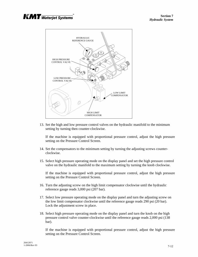
Section 7 Hydraulic System
20412971 1-2006/Rev 03 7-12
13. Set the high and low pressure control valves on the hydraulic manifold to the minimum setting by turning then counter-clockwise.
If the machine is equipped with proportional pressure control, adjust the high pressure setting on the Pressure Control Screen.
14. Set the compensators to the minimum setting by turning the adjusting screws counter-clockwise.
15. Select high pressure operating mode on the display panel and set the high pressure control valve on the hydraulic manifold to the maximum setting by turning the knob clockwise.
If the machine is equipped with proportional pressure control, adjust the high pressure setting on the Pressure Control Screen.
16. Turn the adjusting screw on the high limit compensator clockwise until the hydraulic reference gauge reads 3,000 psi (207 bar).
17. Select low pressure operating mode on the display panel and turn the adjusting screw on the low limit compensator clockwise until the reference gauge reads 290 psi (20 bar). Lock the adjustment screw in place.
18. Select high pressure operating mode on the display panel and turn the knob on the high pressure control valve counter-clockwise until the reference gauge reads 2,000 psi (138 bar).
If the machine is equipped with proportional pressure control, adjust the high pressure setting on the Pressure Control Screen.
LOW PRESSURE CONTROL VALVE
HYDRAULIC REFERENCE GAUGE
HIGH PRESSURE CONTROL VALVE
HIGH LIMIT COMPENSATOR
LOW LIMIT COMPENSATOR
Section 7 Hydraulic System
20412971 1-2006/Rev 03 7-13
19. Open the high pressure water control valve, allowing water to flow. Set the desired high operating pressure by adjusting the high pressure control valve.
If the machine is equipped with proportional pressure control, select the high operating pressure on the Pressure Control Screen.
20. While the machine is running and high pressure water is flowing, select low pressure operating mode. Set the desired low operating pressure by adjusting the low pressure control valve.
Hydraulic Pump or Electric Motor Replacement
The following procedures are used to replace the hydraulic pump or the electric motor.
Hydraulic Pump Replacement
1. Turn the machine off and observe the appropriate Lockout/Tagout procedures.
Severe injury can result if the machine is not properly locked out. Observe electrical Lockout/Tagout procedures before proceeding.
Ensure all pressure is relieved or blocked from the hydraulic and high pressure circuits before proceeding.
2. Loosen the hold down screws on the proximity switches to allow the hydraulic oil in the cylinders and hoses to drain back to the reservoir. It will take approximately five minutes for the oil to drain.
3. Drain the oil reservoir by connecting the inlet hose from an oil transfer pump to the drain valve on the reservoir. Open the shut off valve on the drain and pump the used oil out to a container. Close the shut off valve and remove the inlet hose from the drain valve.
The removed oil should not be reused. It is recommended that the empty reservoir be flushed with a few gallons of clean oil to remove settled debris from the bottom
of the reservoir.
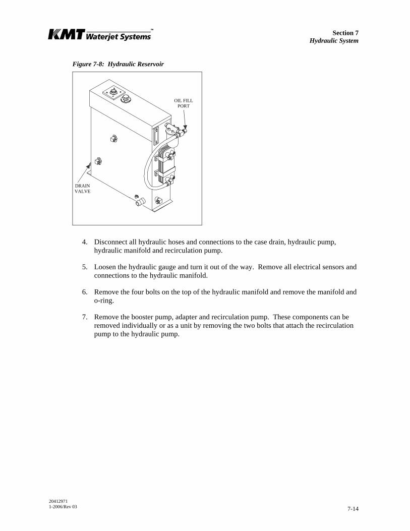
Section 7 Hydraulic System
20412971 1-2006/Rev 03 7-14
Figure 7-8: Hydraulic Reservoir
4. Disconnect all hydraulic hoses and connections to the case drain, hydraulic pump, hydraulic manifold and recirculation pump.
5. Loosen the hydraulic gauge and turn it out of the way. Remove all electrical sensors and connections to the hydraulic manifold.
6. Remove the four bolts on the top of the hydraulic manifold and remove the manifold and o-ring.
7. Remove the booster pump, adapter and recirculation pump. These components can be removed individually or as a unit by removing the two bolts that attach the recirculation pump to the hydraulic pump.
OIL FILL PORT
DRAIN VALVE
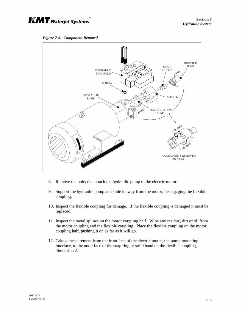
Section 7 Hydraulic System
20412971 1-2006/Rev 03 7-15
Figure 7-9: Component Removal
8. Remove the bolts that attach the hydraulic pump to the electric motor.
9. Support the hydraulic pump and slide it away from the motor, disengaging the flexible coupling.
10. Inspect the flexible coupling for damage. If the flexible coupling is damaged it must be replaced.
11. Inspect the metal splines on the motor coupling half. Wipe any residue, dirt or oil from the motor coupling and the flexible coupling. Place the flexible coupling on the motor coupling half, pushing it on as far as it will go.
12. Take a measurement from the front face of the electric motor, the pump mounting interface, to the outer face of the snap ring or solid band on the flexible coupling, dimension A.
ADAPTER
O-RING
SHAFT COUPLING
BOOSTER PUMP
HYDRAULIC MANIFOLD
COMPONENTS REMOVED AS A UNIT
RECIRCULATION PUMP
HYDRAULIC PUMP

Section 7 Hydraulic System
20412971 1-2006/Rev 03 7-16
Figure 7-10: Pump Coupling Dimension
From dimension A, subtract 5/16 inch for 30, 50 and 60 horsepower motors, and 1/4 inch for 75 and 100 horsepower motors.
13. Loosen the pinch bolt in the pump coupling half on the old pump and remove the coupling half. Inspect the metal splines for damage. If the coupling half is not damaged it can be reused on the new pump.
14. Wipe any residue, dirt or oil from the pump coupling half. Slide the existing coupling half, or a new coupling half if necessary, onto the splined shaft of the new pump.
Set the position of the pump coupling half by measuring from the pump mounting face to the outer face of the coupling teeth, dimension B. On 30, 50 and 60 horsepower models, B = (A - 0.313), on 75 and 100 horsepower models B = (A - 0.250).
15. Tighten the pinch bolt and torque to 36 ft-lbs (49 Nm) for 30 horsepower models, 63 ft-lbs (86 Nm) for 50 and 60 horsepower models, and 218 ft-lbs (295 Nm) for 75 and 100 horsepower models.
16. Place the hydraulic pump on the motor, ensuring the coupling teeth mesh into the flexible coupling. Force should not be required.
17. Verify that the mating surfaces of the motor and pump meet without resistance from the coupling.
18. Replace the pump mounting bolts and torque to the specifications in Table 7-3, Torque Specifications.
19. Install the recirculation pump, adapter and booster pump.
20. Install the hydraulic manifold ensuring that the o-ring is properly positioned. Torque the mounting bolts to the specifications in Table 7-3.
MOTOR SHAFT
HYDRAULIC PUMP
FLEXIBLE COUPLING
MOTOR COUPLING HALF PUMP COUPLING
HALF
FLANGE
PUMP SHAFT
PINCH BOLT
Section 7 Hydraulic System
20412971 1-2006/Rev 03 7-17
21. Reconnect all hydraulic hoses, connections and electrical sensors.
22. Tighten the hold down screws on the proximity switches and torque to 140-160 in-lbs (16-18 Nm).
Ensure that the proximity switches are properly installed and secured prior to starting the motor. Failure to tighten the two hold down screws on each switch
will result in the spray of hydraulic oil.
23. Refill the hydraulic reservoir following the procedure, Hydraulic Oil Replacement.
24. Start the motor and apply full high pressure water pressure. Inspect for hydraulic leaks and note any unusual sounds from the motor or pump assembly.
Table 7-3 Torque Specifications
30 HP 50 and 60 HP 75 and 100 HP
Pump mounting bolts 55 ft-lb (75 Nm) 110 ft-lb (149 Nm) 200 ft-lb (271 Nm)
Manifold mounting bolts 35 ft-lb (47 Nm) 35 ft-lb (47 Nm) 45 ft-lb (61 Nm)
Motor coupling half bolts 36 ft-lb (49 Nm) 36 ft-lb (49 Nm) 85 ft-lb (115 Nm)
Electric Motor Replacement
1. Complete Steps 1-10 in the previous procedure.
2. Open the junction box on the motor and remove all electrical leads. Loosen the lock nut, disconnect and remove the flexible electrical cable from the junction box.
3. Remove the bolts attaching the motor to the vibration isolation mounts and remove the old motor from the frame.
4. Stand the new motor on the fan cowl with the shaft pointing upward.
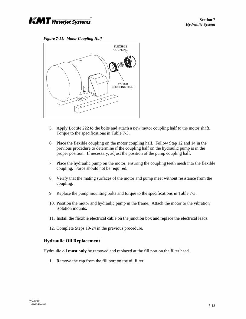
Section 7 Hydraulic System
20412971 1-2006/Rev 03 7-18
Figure 7-11: Motor Coupling Half
5. Apply Loctite 222 to the bolts and attach a new motor coupling half to the motor shaft. Torque to the specifications in Table 7-3.
6. Place the flexible coupling on the motor coupling half. Follow Step 12 and 14 in the previous procedure to determine if the coupling half on the hydraulic pump is in the proper position. If necessary, adjust the position of the pump coupling half.
7. Place the hydraulic pump on the motor, ensuring the coupling teeth mesh into the flexible coupling. Force should not be required.
8. Verify that the mating surfaces of the motor and pump meet without resistance from the coupling.
9. Replace the pump mounting bolts and torque to the specifications in Table 7-3.
10. Position the motor and hydraulic pump in the frame. Attach the motor to the vibration isolation mounts.
11. Install the flexible electrical cable on the junction box and replace the electrical leads.
12. Complete Steps 19-24 in the previous procedure.
Hydraulic Oil Replacement
Hydraulic oil must only be removed and replaced at the fill port on the filter head.
1. Remove the cap from the fill port on the oil filter.
FLEXIBLE COUPLING
MOTOR COUPLING HALF
Section 7 Hydraulic System
20412971 1-2006/Rev 03 7-19
To ensure cleanliness, the oil fill port must be used to pump oil into the reservoir. Filling at this point guarantees the hydraulic oil will pass through the oil filter
before entering the reservoir.
2. Connect the discharge hose from an oil transfer pump to the fill port and pump the fresh oil into the reservoir.
NOTE
Oil from a new drum does not meet the cleanliness requirements of the hydraulic system. For this reason, it is important to use an oil transfer pump that will force
oil through the return filter into the reservoir.
3. Check the oil sight gauge on the reservoir to ensure proper fill level.
4. Remove the hose from the case drain on the main hydraulic pump to make sure the pump case fills with oil. With the hose removed, head pressure from the reservoir will force oil into the pump case.
Oil in the pump case provides internal lubrication for the main hydraulic pump. Failure to the fill the pump case with oil will allow air to become trapped inside,
damaging the pump.
5. Disconnect the discharge hose from the fill port and replace the fill port cap.
6. Follow the initial startup sequence in Section 4, Operation, to ensure the system fills with oil.
7. Check the sight gauge again and follow the same procedure to add additional oil if necessary.
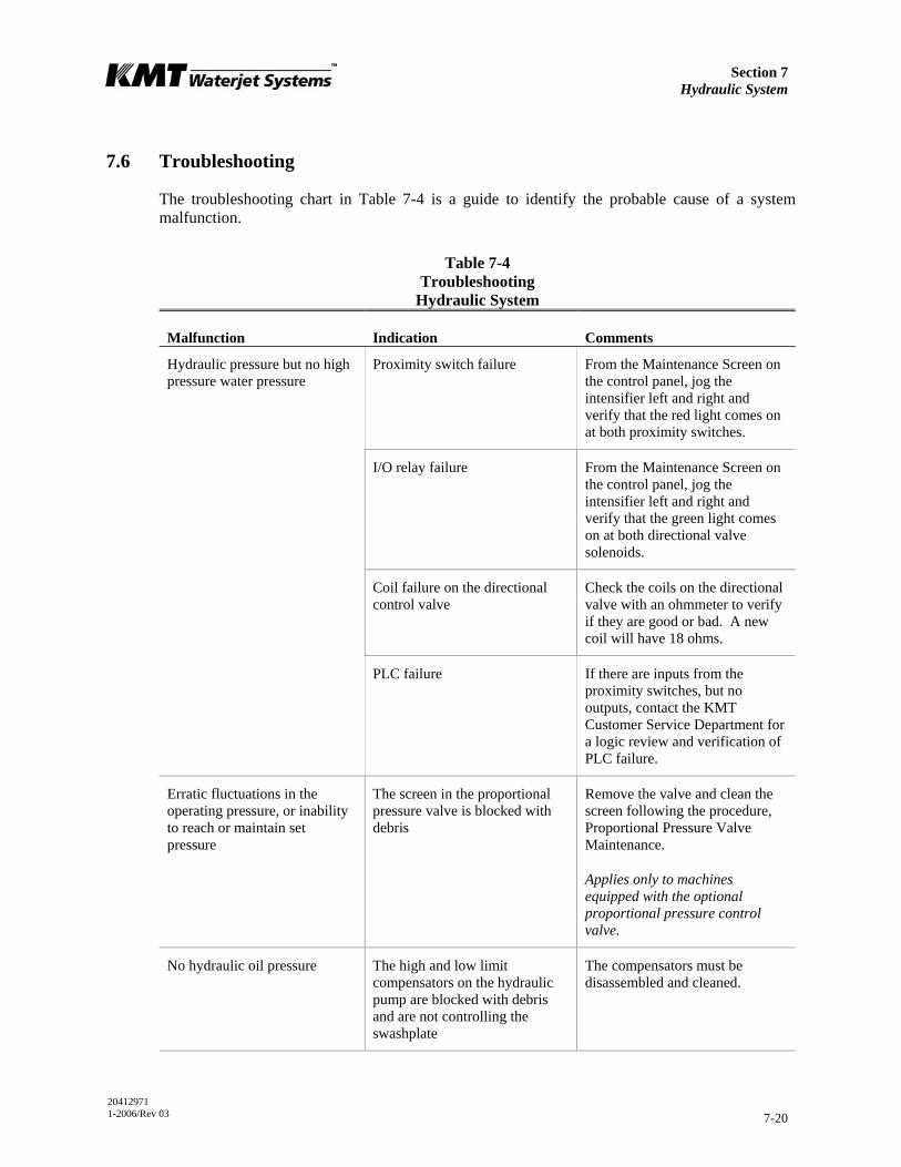
Section 7 Hydraulic System
20412971 1-2006/Rev 03 7-20
7.6 Troubleshooting
The troubleshooting chart in Table 7-4 is a guide to identify the probable cause of a system malfunction.
Table 7-4 Troubleshooting
Hydraulic System
Malfunction Indication Comments
Proximity switch failure From the Maintenance Screen on the control panel, jog the intensifier left and right and verify that the red light comes on at both proximity switches.
I/O relay failure From the Maintenance Screen on the control panel, jog the intensifier left and right and verify that the green light comes on at both directional valve solenoids.
Coil failure on the directional control valve
Check the coils on the directional valve with an ohmmeter to verify if they are good or bad. A new coil will have 18 ohms.
Hydraulic pressure but no high pressure water pressure
PLC failure If there are inputs from the proximity switches, but no outputs, contact the KMT Customer Service Department for a logic review and verification of PLC failure.
Erratic fluctuations in the operating pressure, or inability to reach or maintain set pressure
The screen in the proportional pressure valve is blocked with debris
Remove the valve and clean the screen following the procedure, Proportional Pressure Valve Maintenance.
Applies only to machines equipped with the optional proportional pressure control valve.
No hydraulic oil pressure The high and low limit compensators on the hydraulic pump are blocked with debris and are not controlling the swashplate
The compensators must be disassembled and cleaned.
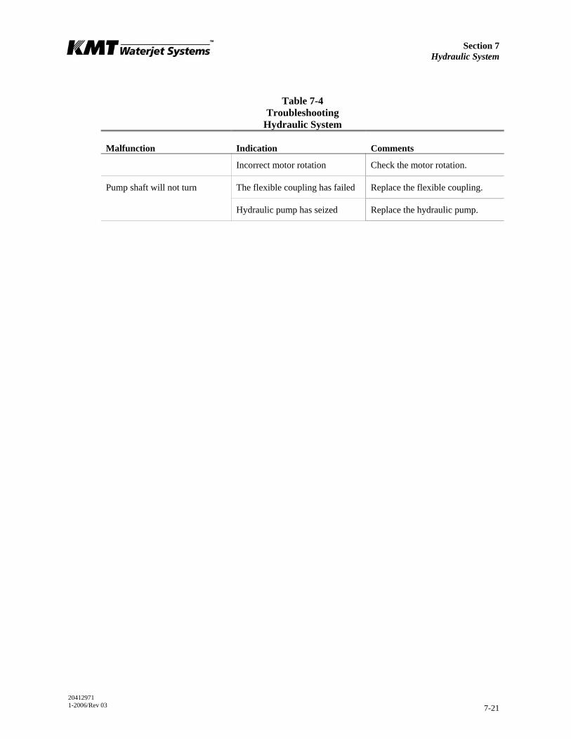
Section 7 Hydraulic System
20412971 1-2006/Rev 03 7-21
Table 7-4 Troubleshooting
Hydraulic System
Malfunction Indication Comments
Incorrect motor rotation Check the motor rotation.
The flexible coupling has failed Replace the flexible coupling. Pump shaft will not turn
Hydraulic pump has seized Replace the hydraulic pump.
20412989 1-2006/Rev 03 8-1
SECTION 8 ELECTRICAL SYSTEM
8.1 Overview
All SL-V Plus models are equipped with integral motor starter and control circuitry, enclosed in the electrical panel. The operator controls the machine primarily through a touch-screen control panel that communicates with the programmable logic controller (PLC). A series of sensors provide automatic shutdown logic and diagnostics.
Major system components include the electric motor, control panel, high voltage and control components, and the wiring harness that connects the sensors and solenoid valves to the PLC.
8.2 Optional System Components
The following system options are available at the time of purchase, or as upgrade kits for existing equipment.
• A pressure transducer allows the operating pressure to be viewed from the display panel.
• Proportional pressure control allows the operator to select or vary the hydraulic operating pressure from the control panel or from a remote console.
• A modem option permits remote monitoring for troubleshooting and software updates.
• A 37-pin amphenol connector, mounted in the side of the electrical enclosure, is available for all remote connections.
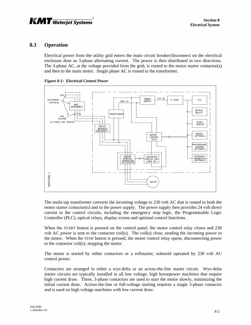
Section 8 Electrical System
20412989 1-2006/Rev 03 8-2
8.3 Operation
Electrical power from the utility grid enters the main circuit breaker/disconnect on the electrical enclosure door as 3-phase alternating current. The power is then distributed in two directions. The 3-phase AC, at the voltage provided from the grid, is routed to the motor starter contactor(s) and then to the main motor. Single phase AC is routed to the transformer.
Figure 8-1: Electrical Control Power
The multi-tap transformer converts the incoming voltage to 230 volt AC that is routed to both the motor starter contactor(s) and to the power supply. The power supply then provides 24 volt direct current to the control circuits, including the emergency stop logic, the Programmable Logic Controller (PLC), optical relays, display screen and optional control functions.
When the START button is pressed on the control panel, the motor control relay closes and 230 volt AC power is sent to the contactor coil(s). The coil(s) close, sending the incoming power to the motor. When the STOP button is pressed, the motor control relay opens, disconnecting power to the contactor coil(s), stopping the motor.
The motor is started by either contactors or a softstarter, solenoid operated by 230 volt AC control power.
Contactors are arranged in either a wye-delta or an across-the-line starter circuit. Wye-delta starter circuits are typically installed in all low voltage, high horsepower machines that require high current draw. Three, 3-phase contactors are used to start the motor slowly, minimizing the initial current draw. Across-the-line or full-voltage starting requires a single 3-phase contactor and is used on high voltage machines with low current draw.
8007
9189
_1
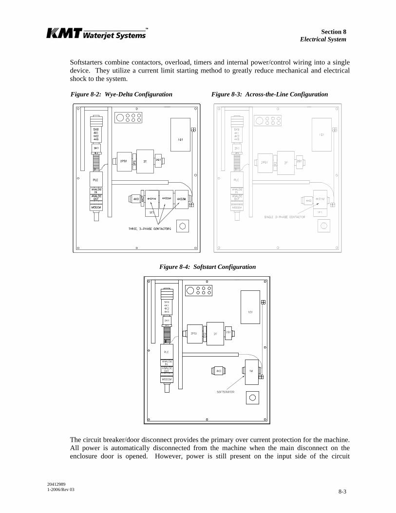
Section 8 Electrical System
20412989 1-2006/Rev 03 8-3
Softstarters combine contactors, overload, timers and internal power/control wiring into a single device. They utilize a current limit starting method to greatly reduce mechanical and electrical shock to the system.
Figure 8-2: Wye-Delta Configuration Figure 8-3: Across-the-Line Configuration
Figure 8-4: Softstart Configuration
The circuit breaker/door disconnect provides the primary over current protection for the machine. All power is automatically disconnected from the machine when the main disconnect on the enclosure door is opened. However, power is still present on the input side of the circuit
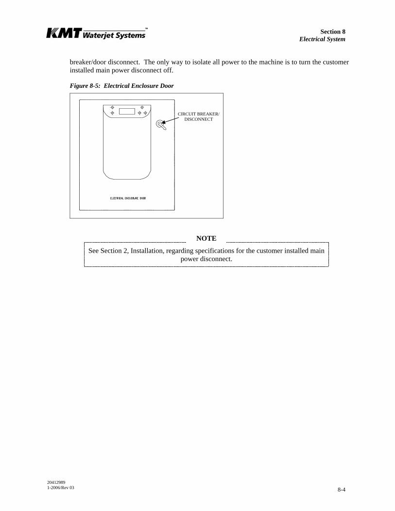
Section 8 Electrical System
20412989 1-2006/Rev 03 8-4
breaker/door disconnect. The only way to isolate all power to the machine is to turn the customer installed main power disconnect off.
Figure 8-5: Electrical Enclosure Door
NOTE
See Section 2, Installation, regarding specifications for the customer installed main power disconnect.
CIRCUIT BREAKER/ DISCONNECT
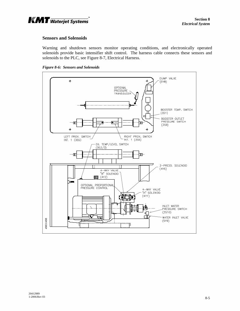
Section 8 Electrical System
20412989 1-2006/Rev 03 8-5
Sensors and Solenoids
Warning and shutdown sensors monitor operating conditions, and electronically operated solenoids provide basic intensifier shift control. The harness cable connects these sensors and solenoids to the PLC, see Figure 8-7, Electrical Harness.
Figure 8-6: Sensors and Solenoids
4983
1498
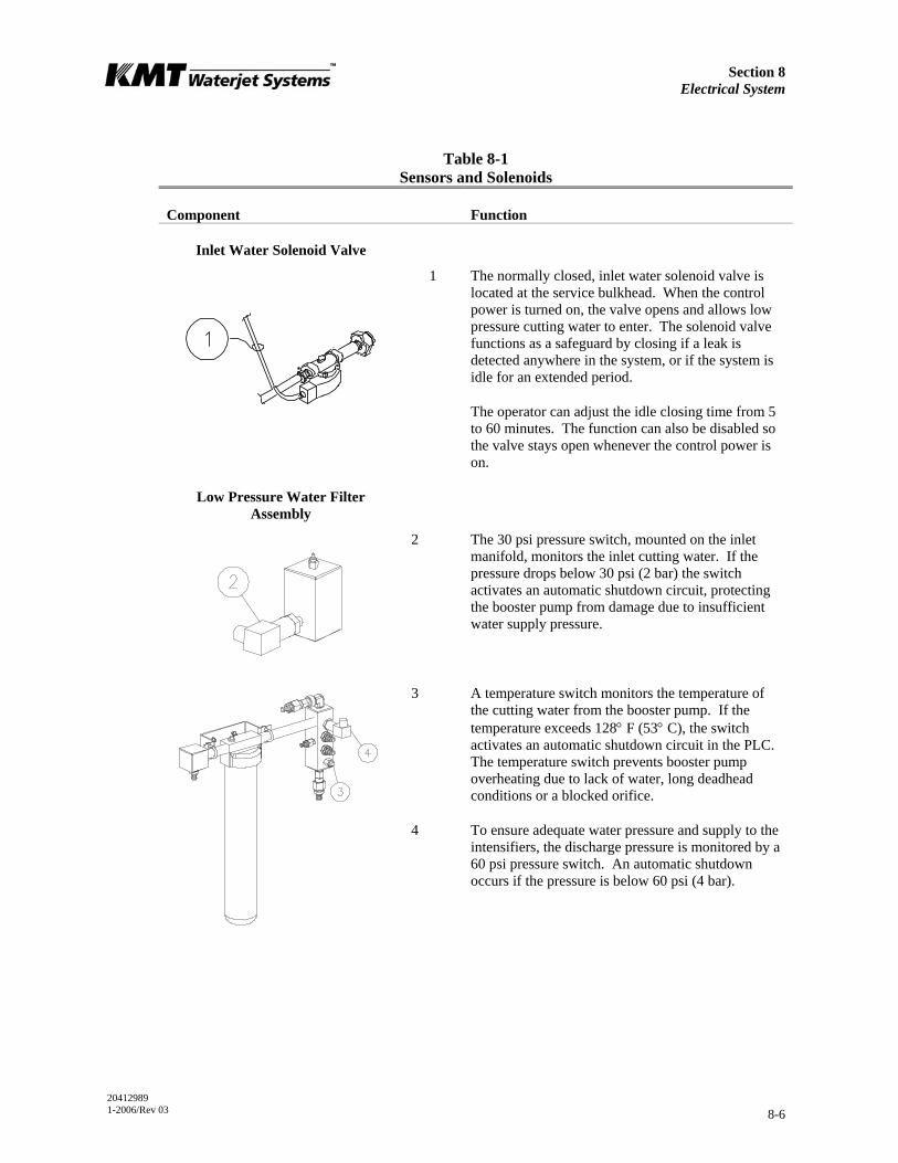
Section 8 Electrical System
20412989 1-2006/Rev 03 8-6
Table 8-1 Sensors and Solenoids
Component Function
Inlet Water Solenoid Valve
1 The normally closed, inlet water solenoid valve is located at the service bulkhead. When the control power is turned on, the valve opens and allows low pressure cutting water to enter. The solenoid valve functions as a safeguard by closing if a leak is detected anywhere in the system, or if the system is idle for an extended period.
The operator can adjust the idle closing time from 5 to 60 minutes. The function can also be disabled so the valve stays open whenever the control power is on.
Low Pressure Water Filter Assembly
2 The 30 psi pressure switch, mounted on the inlet manifold, monitors the inlet cutting water. If the pressure drops below 30 psi (2 bar) the switch activates an automatic shutdown circuit, protecting the booster pump from damage due to insufficient water supply pressure.
3 A temperature switch monitors the temperature of the cutting water from the booster pump. If the temperature exceeds 128° F (53° C), the switch activates an automatic shutdown circuit in the PLC. The temperature switch prevents booster pump overheating due to lack of water, long deadhead conditions or a blocked orifice.
4 To ensure adequate water pressure and supply to the intensifiers, the discharge pressure is monitored by a 60 psi pressure switch. An automatic shutdown occurs if the pressure is below 60 psi (4 bar).
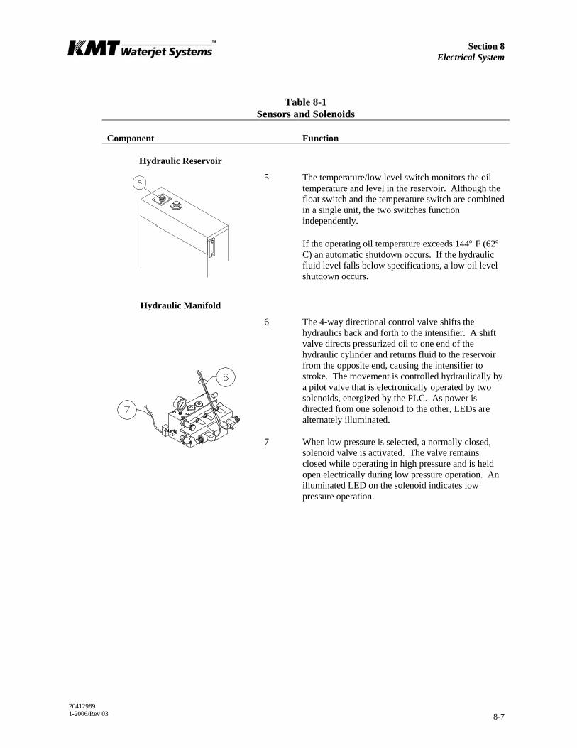
Section 8 Electrical System
20412989 1-2006/Rev 03 8-7
Table 8-1 Sensors and Solenoids
Component Function
Hydraulic Reservoir
5 The temperature/low level switch monitors the oil temperature and level in the reservoir. Although the float switch and the temperature switch are combined in a single unit, the two switches function independently.
If the operating oil temperature exceeds 144° F (62° C) an automatic shutdown occurs. If the hydraulic fluid level falls below specifications, a low oil level shutdown occurs.
Hydraulic Manifold
6 The 4-way directional control valve shifts the hydraulics back and forth to the intensifier. A shift valve directs pressurized oil to one end of the hydraulic cylinder and returns fluid to the reservoir from the opposite end, causing the intensifier to stroke. The movement is controlled hydraulically by a pilot valve that is electronically operated by two solenoids, energized by the PLC. As power is directed from one solenoid to the other, LEDs are alternately illuminated.
7 When low pressure is selected, a normally closed, solenoid valve is activated. The valve remains closed while operating in high pressure and is held open electrically during low pressure operation. An illuminated LED on the solenoid indicates low pressure operation.
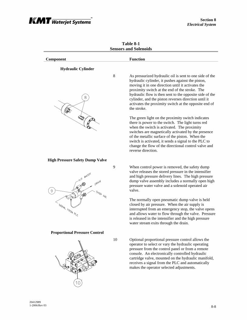
Section 8 Electrical System
20412989 1-2006/Rev 03 8-8
Table 8-1 Sensors and Solenoids
Component Function
Hydraulic Cylinder
8 As pressurized hydraulic oil is sent to one side of the hydraulic cylinder, it pushes against the piston, moving it in one direction until it activates the proximity switch at the end of the stroke. The hydraulic flow is then sent to the opposite side of the cylinder, and the piston reverses direction until it activates the proximity switch at the opposite end of the stroke.
The green light on the proximity switch indicates there is power to the switch. The light turns red when the switch is activated. The proximity switches are magnetically activated by the presence of the metallic surface of the piston. When the switch is activated, it sends a signal to the PLC to change the flow of the directional control valve and reverse direction.
High Pressure Safety Dump Valve
9 When control power is removed, the safety dump valve releases the stored pressure in the intensifier and high pressure delivery lines. The high pressure dump valve assembly includes a normally open high pressure water valve and a solenoid operated air valve.
The normally open pneumatic dump valve is held closed by air pressure. When the air supply is interrupted from an emergency stop, the valve opens and allows water to flow through the valve. Pressure is released in the intensifier and the high pressure water stream exits through the drain.
Proportional Pressure Control
10 Optional proportional pressure control allows the operator to select or vary the hydraulic operating pressure from the control panel or from a remote console. An electronically controlled hydraulic cartridge valve, mounted on the hydraulic manifold, receives a signal from the PLC and automatically makes the operator selected adjustments.
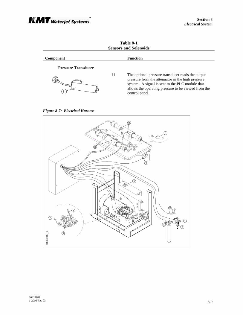
Section 8 Electrical System
20412989 1-2006/Rev 03 8-9
Table 8-1 Sensors and Solenoids
Component Function
Pressure Transducer
11 The optional pressure transducer reads the output pressure from the attenuator in the high pressure system. A signal is sent to the PLC module that allows the operating pressure to be viewed from the control panel.
Figure 8-7: Electrical Harness
8008
0500
_1

Section 8 Electrical System
20412989 1-2006/Rev 03 8-10
Softstarter
The softstarter is a reduced voltage starter that minimizes system mechanical and electrical stress by reducing current surges. A RUN/FAULT LED display relays device status information and fault diagnostics. A flashing red LED indicates a fault, either internal to the softstarter, or with the incoming power or motor. The number of flashes in sequence, indicates the fault, see Table 8-4, Troubleshooting.
NOTE
The blue arrow selector above the LED display is the setting for flow load amps. The arrow must be set at the FLA for the motor.
DIP Switch Settings
DIP switches are used to set the start/stop profile, overload trip class and auxiliary contact characteristics.Open the tab on the top, right of the softstarter to access the eight DIP switches. Table 8-2 illustrates the switch settings, starting from the left.
Table 8-2 DIP Switch Settings
Number Setting Position
1 Start time (5 seconds) Up
2 Start time (5 seconds) Down
3 Current limit above Full Load Amps (350%) Up
4 Current limit above Full Load Amps (350%) Up
5 Trip class (10) Up
6 Trip class (10) Down
7 Overload reset (Auto) Up
8 Optional auxiliary (Normal) Down

Section 8 Electrical System
20412989 1-2006/Rev 03 8-11
8.4 Service and Maintenance Procedures
Electrical components require minimal service. The proximity switches on the hydraulic cylinder and the optical relay switches in the controls subassembly may require replacement.
NOTE
Refer to Section 12, Parts List for a complete listing of replacement parts and part numbers.
Proximity Switch Maintenance
A proximity switch has failed and needs to be replaced if the LEDs do not change state, indicating they are not sensing the piston, if an LED flashes continuously, or if the appropriate input is not noted on the PLC processor annunciator light panel in the electrical enclosure.
Figure 8-8: Proximity Switch
1. Turn the machine off and observe the appropriate Lockout/Tagout procedures.
Severe injury can result if the machine is not properly locked out. Observe electrical Lockout/Tagout procedures before performing maintenance on the
system components.
Ensure all pressure is relieved or blocked from the hydraulic and high pressure circuits before performing maintenance.
2. Remove the electrical cable from the failed proximity switch.
3. Remove the two socket head screws, the failed switch and the o-ring spacer.
O-RING SPACER
PROXIMITY SWITCH

Section 8 Electrical System
20412989 1-2006/Rev 03 8-12
4. Install a new proximity switch by positioning the o-ring spacer and the switch. Ensure the o-rings are correctly oriented.
5. Apply JL-M grease to the threads on the screws and tighten to 140-160 in-lbs (16-18 Nm).
Ensure that the proximity switch is properly installed and secured prior to starting the machine. Failure to tighten the two hold down screws on each switch will
result in the spray of hydraulic oil.
Optical Relay Maintenance
The four optical relays identified in Table 8-3 change the state of the associated solenoid valves. If the relay or the fuse for the relay fails, the state will not change. For example, if the relay controlling the two-pressure solenoid valve fails, the machine will not switch between low and high pressure operation.
Table 8-3 Optical Relays
Label Component Function
4K1 Directional Control Valve, Solenoid A Switches the direction of the hydraulic flow
4K2 Directional Control Valve, Solenoid B Switches the direction of the hydraulic flow
4K5 Two Pressure Solenoid Valve Switches to low or high pressure operation
5K9 Water Supply Valve Opens and closes the inlet water solenoid valve
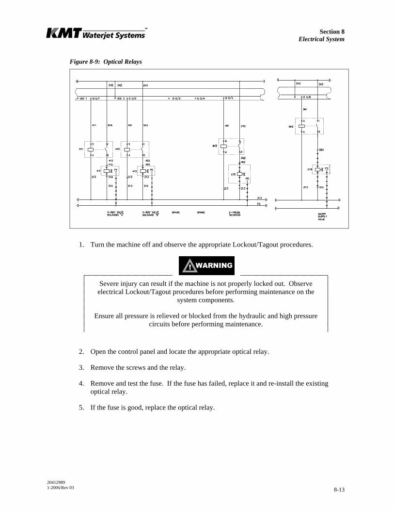
Section 8 Electrical System
20412989 1-2006/Rev 03 8-13
Figure 8-9: Optical Relays
1. Turn the machine off and observe the appropriate Lockout/Tagout procedures.
Severe injury can result if the machine is not properly locked out. Observe electrical Lockout/Tagout procedures before performing maintenance on the
system components.
Ensure all pressure is relieved or blocked from the hydraulic and high pressure circuits before performing maintenance.
2. Open the control panel and locate the appropriate optical relay.
3. Remove the screws and the relay.
4. Remove and test the fuse. If the fuse has failed, replace it and re-install the existing optical relay.
5. If the fuse is good, replace the optical relay.
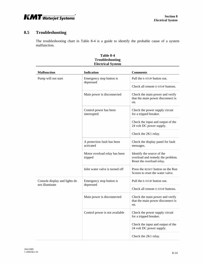
Section 8 Electrical System
20412989 1-2006/Rev 03 8-14
8.5 Troubleshooting
The troubleshooting chart in Table 8-4 is a guide to identify the probable cause of a system malfunction.
Table 8-4 Troubleshooting Electrical System
Malfunction Indication Comments
Pull the E-STOP button out. Emergency stop button is depressed
Check all remote E-STOP buttons.
Main power is disconnected Check the main power and verify that the main power disconnect is on.
Check the power supply circuit for a tripped breaker.
Check the input and output of the 24 volt DC power supply.
Control power has been interrupted
Check the 2K1 relay.
Pump will not start
A protection fault has been activated
Check the display panel for fault messages.
Motor overload relay has been tripped
Identify the source of the overload and remedy the problem. Reset the overload relay.
Inlet water valve is turned off Press the RESET button on the Run Screen to reset the water valve.
Pull the E-STOP button out. Emergency stop button is depressed
Check all remote E-STOP buttons.
Main power is disconnected Check the main power and verify that the main power disconnect is on.
Check the power supply circuit for a tripped breaker.
Check the input and output of the 24 volt DC power supply.
Console display and lights do not illuminate
Control power is not available
Check the 2K1 relay.
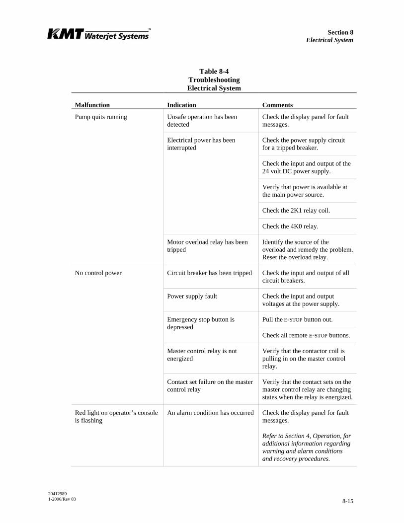
Section 8 Electrical System
20412989 1-2006/Rev 03 8-15
Table 8-4 Troubleshooting Electrical System
Malfunction Indication Comments
Pump quits running Unsafe operation has been detected
Check the display panel for fault messages.
Check the power supply circuit for a tripped breaker.
Check the input and output of the 24 volt DC power supply.
Verify that power is available at the main power source.
Check the 2K1 relay coil.
Electrical power has been interrupted
Check the 4K0 relay.
Motor overload relay has been tripped
Identify the source of the overload and remedy the problem. Reset the overload relay.
No control power Circuit breaker has been tripped Check the input and output of all circuit breakers.
Power supply fault Check the input and output voltages at the power supply.
Pull the E-STOP button out. Emergency stop button is depressed
Check all remote E-STOP buttons.
Master control relay is not energized
Verify that the contactor coil is pulling in on the master control relay.
Contact set failure on the master control relay
Verify that the contact sets on the master control relay are changing states when the relay is energized.
Red light on operator’s console is flashing
An alarm condition has occurred Check the display panel for fault messages.
Refer to Section 4, Operation, for additional information regarding warning and alarm conditions and recovery procedures.
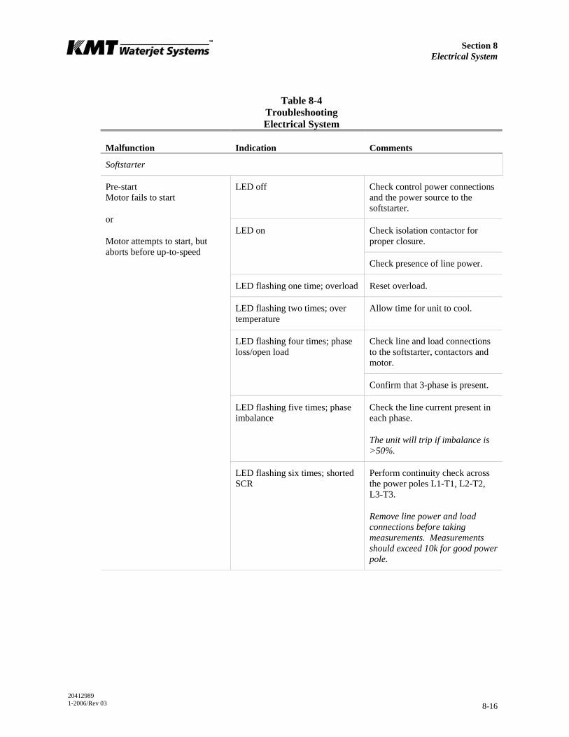
Section 8 Electrical System
20412989 1-2006/Rev 03 8-16
Table 8-4 Troubleshooting Electrical System
Malfunction Indication Comments
Softstarter
LED off Check control power connections and the power source to the softstarter.
LED on Check isolation contactor for proper closure.
Check presence of line power.
LED flashing one time; overload Reset overload.
LED flashing two times; over temperature
Allow time for unit to cool.
LED flashing four times; phase loss/open load
Check line and load connections to the softstarter, contactors and motor.
Confirm that 3-phase is present.
LED flashing five times; phase imbalance
Check the line current present in each phase.
The unit will trip if imbalance is >50%.
Pre-start Motor fails to start
or
Motor attempts to start, but aborts before up-to-speed
LED flashing six times; shorted SCR
Perform continuity check across the power poles L1-T1, L2-T2, L3-T3.
Remove line power and load connections before taking measurements. Measurements should exceed 10k for good power pole.
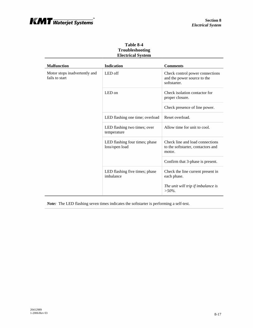
Section 8 Electrical System
20412989 1-2006/Rev 03 8-17
Table 8-4 Troubleshooting Electrical System
Malfunction Indication Comments
LED off Check control power connections and the power source to the softstarter.
LED on Check isolation contactor for proper closure.
Check presence of line power.
LED flashing one time; overload Reset overload.
LED flashing two times; over temperature
Allow time for unit to cool.
LED flashing four times; phase loss/open load
Check line and load connections to the softstarter, contactors and motor.
Confirm that 3-phase is present.
Motor stops inadvertently and fails to start
LED flashing five times; phase imbalance
Check the line current present in each phase.
The unit will trip if imbalance is >50%.
Note: The LED flashing seven times indicates the softstarter is performing a self-test.
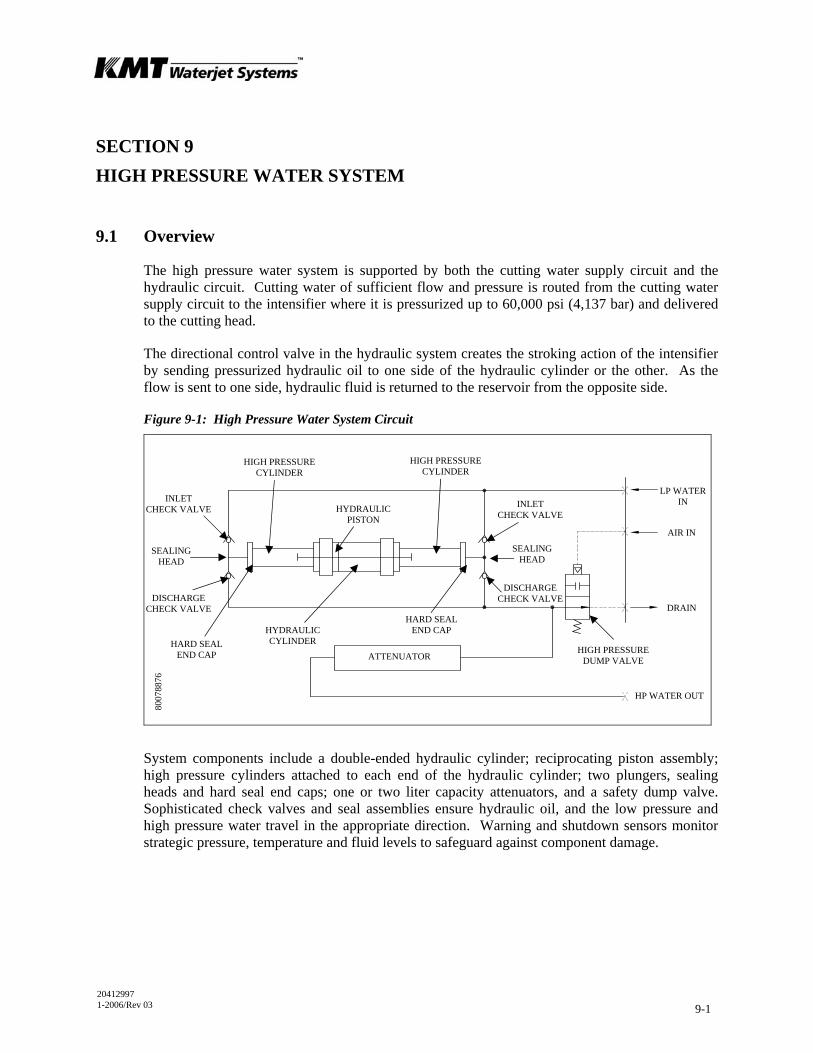
20412997 1-2006/Rev 03 9-1
SECTION 9 HIGH PRESSURE WATER SYSTEM
9.1 Overview
The high pressure water system is supported by both the cutting water supply circuit and the hydraulic circuit. Cutting water of sufficient flow and pressure is routed from the cutting water supply circuit to the intensifier where it is pressurized up to 60,000 psi (4,137 bar) and delivered to the cutting head.
The directional control valve in the hydraulic system creates the stroking action of the intensifier by sending pressurized hydraulic oil to one side of the hydraulic cylinder or the other. As the flow is sent to one side, hydraulic fluid is returned to the reservoir from the opposite side.
Figure 9-1: High Pressure Water System Circuit
System components include a double-ended hydraulic cylinder; reciprocating piston assembly; high pressure cylinders attached to each end of the hydraulic cylinder; two plungers, sealing heads and hard seal end caps; one or two liter capacity attenuators, and a safety dump valve. Sophisticated check valves and seal assemblies ensure hydraulic oil, and the low pressure and high pressure water travel in the appropriate direction. Warning and shutdown sensors monitor strategic pressure, temperature and fluid levels to safeguard against component damage.
ATTENUATOR HIGH PRESSURE
DUMP VALVE
DISCHARGE CHECK VALVE
INLET CHECK VALVE
HIGH PRESSURE CYLINDER
SEALING HEAD
SEALING HEAD
INLET CHECK VALVE
DISCHARGE CHECK VALVE
LP WATERIN
AIR IN
DRAIN
HP WATER OUT
HYDRAULIC CYLINDER
HYDRAULICPISTON
HARD SEAL END CAP
HIGH PRESSURECYLINDER
HARD SEALEND CAP
8007
8876
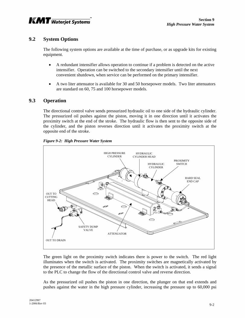
Section 9 High Pressure Water System
20412997 1-2006/Rev 03 9-2
9.2 System Options
The following system options are available at the time of purchase, or as upgrade kits for existing equipment.
• A redundant intensifier allows operation to continue if a problem is detected on the active intensifier. Operation can be switched to the secondary intensifier until the next convenient shutdown, when service can be performed on the primary intensifier.
• A two liter attenuator is available for 30 and 50 horsepower models. Two liter attenuators are standard on 60, 75 and 100 horsepower models.
9.3 Operation
The directional control valve sends pressurized hydraulic oil to one side of the hydraulic cylinder. The pressurized oil pushes against the piston, moving it in one direction until it activates the proximity switch at the end of the stroke. The hydraulic flow is then sent to the opposite side of the cylinder, and the piston reverses direction until it activates the proximity switch at the opposite end of the stroke.
Figure 9-2: High Pressure Water System
The green light on the proximity switch indicates there is power to the switch. The red light illuminates when the switch is activated. The proximity switches are magnetically activated by the presence of the metallic surface of the piston. When the switch is activated, it sends a signal to the PLC to change the flow of the directional control valve and reverse direction.
As the pressurized oil pushes the piston in one direction, the plunger on that end extends and pushes against the water in the high pressure cylinder, increasing the pressure up to 60,000 psi
HARD SEAL END CAP
HYDRAULIC CYLINDER
OUT TO CUTTING
HEAD
OUT TO DRAIN
HIGH PRESSURE CYLINDER
SAFETY DUMP VALVE
ATTENUATOR
HYDRAULIC CYLINDER HEAD
PROXIMITY SWITCH
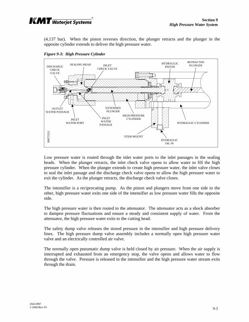
Section 9 High Pressure Water System
20412997 1-2006/Rev 03 9-3
(4,137 bar). When the piston reverses direction, the plunger retracts and the plunger in the opposite cylinder extends to deliver the high pressure water.
Figure 9-3: High Pressure Cylinder
Low pressure water is routed through the inlet water ports to the inlet passages in the sealing heads. When the plunger retracts, the inlet check valve opens to allow water to fill the high pressure cylinder. When the plunger extends to create high pressure water, the inlet valve closes to seal the inlet passage and the discharge check valve opens to allow the high pressure water to exit the cylinder. As the plunger retracts, the discharge check valve closes.
The intensifier is a reciprocating pump. As the piston and plungers move from one side to the other, high pressure water exits one side of the intensifier as low pressure water fills the opposite side.
The high pressure water is then routed to the attenuator. The attenuator acts as a shock absorber to dampen pressure fluctuations and ensure a steady and consistent supply of water. From the attenuator, the high pressure water exits to the cutting head.
The safety dump valve releases the stored pressure in the intensifier and high pressure delivery lines. The high pressure dump valve assembly includes a normally open high pressure water valve and an electrically controlled air valve.
The normally open pneumatic dump valve is held closed by air pressure. When the air supply is interrupted and exhausted from an emergency stop, the valve opens and allows water to flow through the valve. Pressure is released in the intensifier and the high pressure water stream exits through the drain.
INLET WATER
PASSAGE
DISCHARGE CHECK VALVE
INLET CHECK VALVE
SEALING HEAD
INLET WATER PORT
OUTLET WATER PASSAGE
HYDRAULIC OIL IN
EXTENDED PLUNGER
HYDRAULIC PISTON
RETRACTED PLUNGER
HIGH PRESSURE CYLINDER
HYDRAULIC CYLINDER
STEM MOUNT
8007
2333

Section 9 High Pressure Water System
20412997 1-2006/Rev 03 9-4
Redundant Intensifiers
If the machine is equipped with redundant intensifiers, the cutting water supply lines are manually connected to the inlet water ports on the active intensifier. Manual hydraulic valves are opened or closed to direct the hydraulic flow to the active intensifier. Manual high pressure water valves are also opened or closed to direct the high pressure water flow from the active intensifier. Control is switched from one intensifier to the other from the Run Screen on the control panel.
When a machine is equipped with redundant intensifiers, operation can continue on the secondary unit if the primary unit requires maintenance. However, maintenance must not be performed while the machine is in operation.
Maintenance must never be performed on any high pressure components while the machine is operating. All pressure must be relieved or blocked from the hydraulic
and high pressure circuits and the electrical panel must be locked out before performing maintenance.
The following example describes the procedure for changing from one intensifier to the other. In this example, intensifier 2 will become the active intensifier and intensifier 1 will become inactive.
1. Turn the machine off and make sure the EMERGENCY STOP button is depressed.
2. Turn the cutting water supply off.
3. Disconnect the low pressure water supply lines from intensifier 1 and connect them to intensifier 2.
4. Remove the side cover to gain access to the hydraulic hand valves and close the two hydraulic shutoff valves to intensifier 1.
5. Close the high pressure water shutoff valve to intensifier 1.
6. Open the two hydraulic shutoff valves, and the high pressure water shutoff valve to intensifier 2.
7. Select intensifier 2 from the Run Screen on the control display.
8. Turn the cutting water supply on and ensure all cooling water, water supply and cutting water valves are open.
9. Ensure all hydraulic and high pressure fittings, and the proximity switches are properly tightened on intensifier 2.
10. Start the machine in low pressure mode and inspect the hydraulic, high pressure fittings, valves and hoses for leaks.

Section 9 High Pressure Water System
20412997 1-2006/Rev 03 9-5
Dual Intensifiers
If the machine is equipped with dual intensifiers, cutting water supply lines are connected to the inlet water ports on both intensifiers, and the directional control valve supplies hydraulic pressure to both intensifiers.
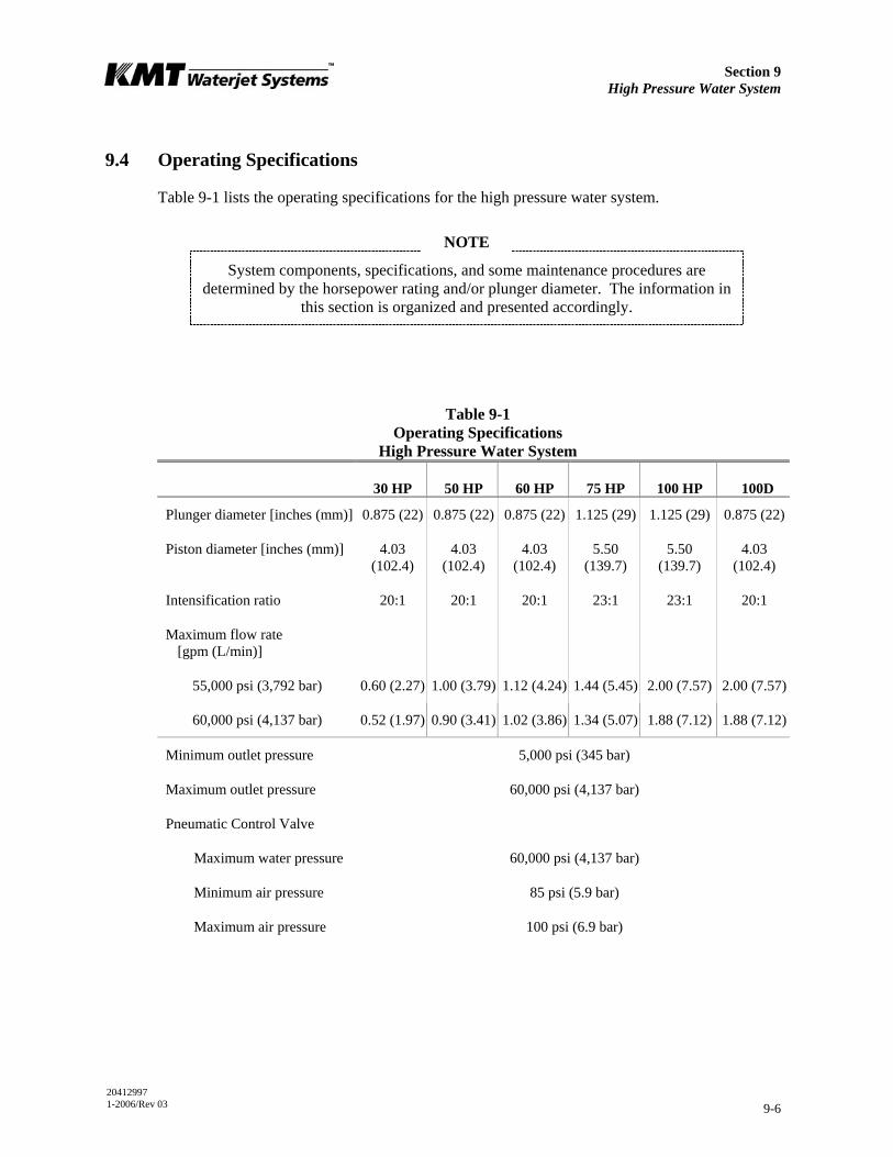
Section 9 High Pressure Water System
20412997 1-2006/Rev 03 9-6
9.4 Operating Specifications
Table 9-1 lists the operating specifications for the high pressure water system.
NOTE
System components, specifications, and some maintenance procedures are determined by the horsepower rating and/or plunger diameter. The information in
this section is organized and presented accordingly.
Table 9-1 Operating Specifications
High Pressure Water System
30 HP 50 HP 60 HP 75 HP 100 HP 100D
Plunger diameter [inches (mm)] 0.875 (22) 0.875 (22) 0.875 (22) 1.125 (29) 1.125 (29) 0.875 (22)
Piston diameter [inches (mm)] 4.03 (102.4)
4.03 (102.4)
4.03 (102.4)
5.50 (139.7)
5.50 (139.7)
4.03 (102.4)
Intensification ratio 20:1 20:1 20:1 23:1 23:1 20:1
Maximum flow rate [gpm (L/min)]
55,000 psi (3,792 bar) 0.60 (2.27) 1.00 (3.79) 1.12 (4.24) 1.44 (5.45) 2.00 (7.57) 2.00 (7.57)
60,000 psi (4,137 bar) 0.52 (1.97) 0.90 (3.41) 1.02 (3.86) 1.34 (5.07) 1.88 (7.12) 1.88 (7.12)
Minimum outlet pressure 5,000 psi (345 bar)
Maximum outlet pressure 60,000 psi (4,137 bar)
Pneumatic Control Valve
Maximum water pressure 60,000 psi (4,137 bar)
Minimum air pressure 85 psi (5.9 bar)
Maximum air pressure 100 psi (6.9 bar)
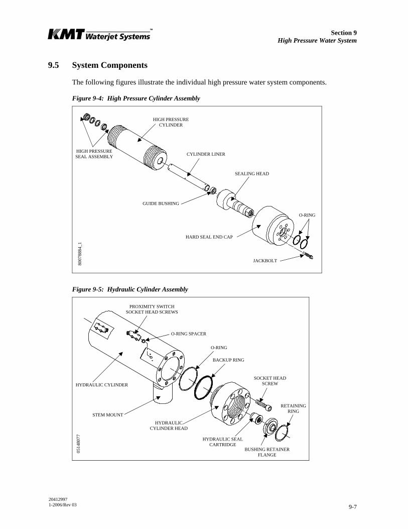
Section 9 High Pressure Water System
20412997 1-2006/Rev 03 9-7
9.5 System Components
The following figures illustrate the individual high pressure water system components.
Figure 9-4: High Pressure Cylinder Assembly
Figure 9-5: Hydraulic Cylinder Assembly
JACKBOLT
O-RING
HARD SEAL END CAP
SEALING HEAD
GUIDE BUSHING
CYLINDER LINER
HIGH PRESSURE CYLINDER
HIGH PRESSURE SEAL ASSEMBLY
8007
8884
_1
RETAINING RING
BACKUP RING
O-RING
O-RING SPACER
PROXIMITY SWITCH SOCKET HEAD SCREWS
STEM MOUNT
HYDRAULIC CYLINDER
BUSHING RETAINER FLANGE
SOCKET HEAD SCREW
HYDRAULIC SEAL CARTRIDGE
HYDRAULIC CYLINDER HEAD
0514
8077
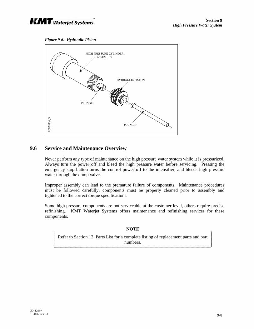
Section 9 High Pressure Water System
20412997 1-2006/Rev 03 9-8
Figure 9-6: Hydraulic Piston
9.6 Service and Maintenance Overview
Never perform any type of maintenance on the high pressure water system while it is pressurized. Always turn the power off and bleed the high pressure water before servicing. Pressing the emergency stop button turns the control power off to the intensifier, and bleeds high pressure water through the dump valve.
Improper assembly can lead to the premature failure of components. Maintenance procedures must be followed carefully; components must be properly cleaned prior to assembly and tightened to the correct torque specifications.
Some high pressure components are not serviceable at the customer level, others require precise refinishing. KMT Waterjet Systems offers maintenance and refinishing services for these components.
NOTE
Refer to Section 12, Parts List for a complete listing of replacement parts and part numbers.
HIGH PRESSURE CYLINDER ASSEMBLY
PLUNGER
PLUNGER
HYDRAULIC PISTON
8007
8884
_3
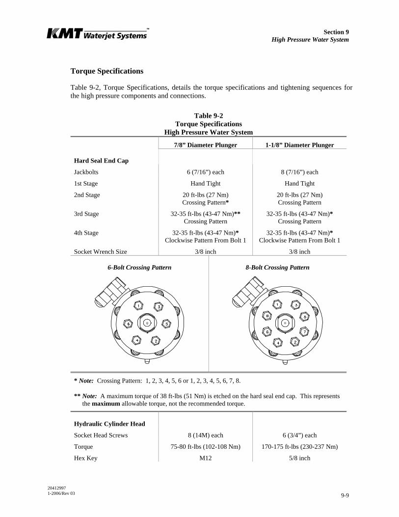
Section 9 High Pressure Water System
20412997 1-2006/Rev 03 9-9
Torque Specifications
Table 9-2, Torque Specifications, details the torque specifications and tightening sequences for the high pressure components and connections.
Table 9-2 Torque Specifications
High Pressure Water System
7/8” Diameter Plunger 1-1/8” Diameter Plunger
Hard Seal End Cap
Jackbolts 6 (7/16”) each 8 (7/16”) each
1st Stage Hand Tight Hand Tight
2nd Stage 20 ft-lbs (27 Nm) Crossing Pattern*
20 ft-lbs (27 Nm) Crossing Pattern
3rd Stage 32-35 ft-lbs (43-47 Nm)** Crossing Pattern
32-35 ft-lbs (43-47 Nm)* Crossing Pattern
4th Stage 32-35 ft-lbs (43-47 Nm)* Clockwise Pattern From Bolt 1
32-35 ft-lbs (43-47 Nm)* Clockwise Pattern From Bolt 1
Socket Wrench Size 3/8 inch 3/8 inch
6-Bolt Crossing Pattern 8-Bolt Crossing Pattern
* Note: Crossing Pattern: 1, 2, 3, 4, 5, 6 or 1, 2, 3, 4, 5, 6, 7, 8.
** Note: A maximum torque of 38 ft-lbs (51 Nm) is etched on the hard seal end cap. This represents the maximum allowable torque, not the recommended torque.
Hydraulic Cylinder Head
Socket Head Screws 8 (14M) each 6 (3/4”) each
Torque 75-80 ft-lbs (102-108 Nm) 170-175 ft-lbs (230-237 Nm)
Hex Key M12 5/8 inch

Section 9 High Pressure Water System
20412997 1-2006/Rev 03 9-10
Table 9-2 Torque Specifications
High Pressure Water System
7/8” Diameter Plunger 1-1/8” Diameter Plunger
Proximity Switch
Socket Head Screws 2 (M6) each 2 (1/4”) each
Torque 140-160 in-lbs (16-18 Nm) 140-160 in-lbs (16-18 Nm)
Hex Key M5 3/16 inch
Stem Mount
Socket Head Screws 4 (M10) each 4 (3/8”) each
Torque 60-65 ft-lbs (80-88 Nm) 35-40 ft-lbs (47-54 Nm)
Hex Key M8 5/16 inch
Sealing Head
Discharge Gland Nut 130 ft-lbs (176 Nm) 200 ft-lbs (271 Nm)
Poppet Retainer 25-30 in-lbs (2.8-3.4 Nm) 25-30 in-lbs (2.8-3.4 Nm)
Pneumatic Control Valve
3/8” HP Inlet Gland Nut 50 ft-lbs (68 Nm) 50 ft-lbs (68 Nm)
1/4” Outlet to Drain 25 ft-lbs (34 Nm) 25 ft-lbs (34 Nm)
Pneumatic Actuator 5 ft-lbs (7 Nm) 5 ft-lbs (7 Nm)
9/16”-1/4” HP Adapter 50 ft-lbs (68 Nm) 50 ft-lbs (68 Nm)
High Pressure Fittings
1/4” HP Gland Nut 25 ft-lbs (34 Nm) 25 ft-lbs (34 Nm)
3/8” HP Gland Nut 50 ft-lbs (68 Nm) 50 ft-lbs (68 Nm)
9/16” HP Gland Nut 110 ft-lbs (149 Nm) 110 ft-lbs (149 Nm)
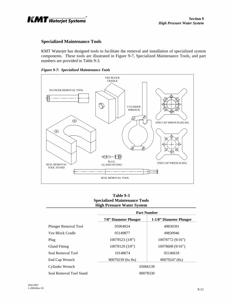
Section 9 High Pressure Water System
20412997 1-2006/Rev 03 9-11
Specialized Maintenance Tools
KMT Waterjet has designed tools to facilitate the removal and installation of specialized system components. These tools are illustrated in Figure 9-7, Specialized Maintenance Tools, and part numbers are provided in Table 9-3.
Figure 9-7: Specialized Maintenance Tools
Table 9-3 Specialized Maintenance Tools High Pressure Water System
Part Number
7/8” Diameter Plunger 1-1/8” Diameter Plunger
Plunger Removal Tool 05004924 49830391
Vee Block Cradle 05149877 49830946
Plug 10079523 (3/8”) 10078772 (9/16”)
Gland Fitting 10078129 (3/8”) 10078608 (9/16”)
Seal Removal Tool 10148674 05146618
End Cap Wrench 80079239 (6x 8x) 80079247 (8x)
Cylinder Wrench 05066139
Seal Removal Tool Stand 80078330
SEAL REMOVAL TOOL STAND
PLUG GLAND FITTING
CYLINDER WRENCH
SEAL REMOVAL TOOL
END CAP WRENCH (6X 8X)
VEE BLOCK CRADLE
PLUNGER REMOVAL TOOL
END CAP WRENCH (8X)
Section 9 High Pressure Water System
20412997 1-2006/Rev 03 9-12
9.7 High and Low Pressure Water Piping
Before performing any maintenance on the high pressure components, it is necessary to remove the high and low pressure water piping. The following procedure should be used to remove and install the piping.
Severe injury can result if the machine is not properly locked out. Observe electrical Lockout/Tagout procedures before performing maintenance on the high
pressure system components.
Ensure all pressure is relieved or blocked from the hydraulic and high pressure circuits before performing maintenance.
1. Turn the cutting water supply off.
2. Loosen and remove the high pressure gland fitting connected to the discharge high pressure check valve. Move the tubing to clear the work area.
3. Loosen and remove the low pressure piping connected to the inlet water port on the hard seal end cap.
4. When the required maintenance has been completed and the components reassembled, connect the low pressure water piping to the inlet water port on the hard seal end cap.
5. Apply Pure Goop to the threads on the high pressure gland fitting. Before installing the high pressure fitting, ensure proper collar position, 1-1/2 to 2-1/2 threads should be exposed. Install and tighten the fitting to the torque specifications in Table 9-2.
6. Turn the cutting water supply on and check for low pressure leaks.
7. Remove the cutting orifice and start the machine. Operate in low pressure mode to flush the high pressure passages.
8. Install the orifice and operate at high pressure to check for leaks.
9.8 High Pressure Cylinder Assembly
KMT Waterjet recommends removing the high pressure cylinder, sealing head and end cap as an assembly for servicing the plunger, high pressure seals, hydraulic piston and seal cartridge. Removing the jackbolts in the hard seal end cap is not recommended except to service the inlet check valve and cone seat on the sealing head.

Section 9 High Pressure Water System
20412997 1-2006/Rev 03 9-13
High Pressure Cylinder Assembly Removal
Prior to removing electrical power or any high or low pressure piping, start the machine from the Maintenance Screen on the control panel. The machine will start in recirculation mode, the dump valve will open and relieve the high pressure in the system.
Press the RIGHT or LEFT arrow to extend the plunger on the end to be serviced. The plunger will extend in the selected direction, allowing full exposure when the unit is disassembled.
1. Turn the machine off and observe the appropriate Lockout/Tagout procedures.
Severe injury can result if the machine is not properly locked out. Observe electrical Lockout/Tagout procedures before proceeding.
Ensure all pressure is relieved or blocked from the hydraulic and high pressure circuits before proceeding.
2. Disconnect the high and low pressure water piping, following the procedure, High and Low Pressure Water Piping.
Due to the weight of the cylinder assembly, adequate support must be provided to prevent damage to the plunger or seals during removal and installation. See Figure 9-7, Specialized Maintenance Tools for tools available to support the high pressure
assembly for this procedure.
3. Position the vee block cradle tool under the cylinder assembly. Unthread and remove the assembly from the hydraulic cylinder head and plunger. The assembly can be rotated with the cylinder wrench or by hand.
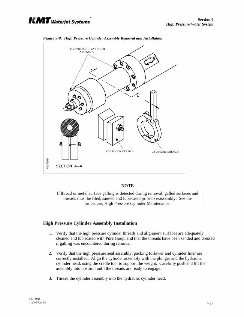
Section 9 High Pressure Water System
20412997 1-2006/Rev 03 9-14
Figure 9-8: High Pressure Cylinder Assembly Removal and Installation
NOTE
If thread or metal surface galling is detected during removal, galled surfaces and threads must be filed, sanded and lubricated prior to reassembly. See the
procedure, High Pressure Cylinder Maintenance.
High Pressure Cylinder Assembly Installation
1. Verify that the high pressure cylinder threads and alignment surfaces are adequately cleaned and lubricated with Pure Goop, and that the threads have been sanded and dressed if galling was encountered during removal.
2. Verify that the high pressure seal assembly, packing follower and cylinder liner are correctly installed. Align the cylinder assembly with the plunger and the hydraulic cylinder head, using the cradle tool to support the weight. Carefully push and lift the assembly into position until the threads are ready to engage.
3. Thread the cylinder assembly into the hydraulic cylinder head.
CYLINDER WRENCH VEE BLOCK CRADLE
HIGH PRESSURE CYLINDER ASSEMBLY
8007
8934
Section 9 High Pressure Water System
20412997 1-2006/Rev 03 9-15
NOTE
If galling occurs during threading, remove the high pressure cylinder assembly and inspect the mating surfaces and threads. Repair surfaces, thoroughly clean, lubricate and thread the cylinder assembly into the hydraulic cylinder head.
4. Connect the high and low pressure water piping, following the procedure, High and Low Pressure Water Piping.
5. Start the machine in low pressure mode to flush air from the high pressure components and to check for obvious leaks. After 5-10 strokes, switch to high pressure operation and check for leaks.
If leaks are detected, turn the machine off and remedy the problem. When the problem has been remedied, repeat the start up procedure, moving from low to high pressure soon after the intensifier starts pumping water. There is no further need to flush air from the system.
High Pressure Cylinder Maintenance
The plunger seal area in the high pressure cylinder bore should be inspected and cleaned each time the high pressure seal assembly is replaced.
1. Clean the sealing area on the inside diameter of the high pressure cylinder and inspect the bore for rings, scratches, pits, residue or other potential leak paths.
Seal material or residue can build up, forming a ring. Running a fingernail across the buildup will cause it to appear as a surface flaw. Grooves or ridges are typically seal debris buildup rather than marks on the inside diameter wall of the cylinder.
2. Polish the inside diameter of the cylinder where the seal will locate with 600-grit wet/dry sandpaper. Hold the sandpaper on the end of your finger and move in a cylindrical wiping motion. Polish in a circumferential motion only. Do not polish or drag the sandpaper along the length of the cylinder.
3. Clean the residue from the inside diameter of the cylinder and re-inspect for surface defects.
Section 9 High Pressure Water System
20412997 1-2006/Rev 03 9-16
NOTE
The high pressure cylinders on some models in the SL-V series are manufactured with an inner and an outer cylinder. The inner cylinder has a spiral groove cut into it and is press-fit inside the outer cylinder. This manufacturing process increases
the fatigue strength and extends the life of the cylinder.
The ends of the high pressure cylinder often show a ‘step’ where the inner sleeve extends slightly beyond the outer sleeve, and the spiral groove could appear to be a
crack on either end of the cylinder. These characteristics are normal and do not indicate a flaw in the cylinder.
9.9 Hard Seal End Caps
KMT Waterjet recommends loosening the jackbolts and removing the hard seal end caps (HSEC) only to service the inlet check valve and the cone seat on the sealing head.
Hard Seal End Cap Removal
Prior to removing electrical power or any high or low pressure piping, start the machine from the Maintenance Screen on the control panel. The machine will start in recirculation mode, the dump valve will open and relieve the high pressure in the system.
Press the RIGHT or LEFT arrow to retract the plunger on the opposite end to be serviced. The plunger will extend in the selected direction, allowing full exposure when the unit is disassembled.
1. Turn the machine off and observe the appropriate Lockout/Tagout procedures.
Severe injury can result if the machine is not properly locked out. Observe electrical Lockout/Tagout procedures before proceeding.
Ensure all pressure is relieved or blocked from the hydraulic and high pressure circuits before proceeding.
2. Disconnect the high and low pressure water piping, following the procedure, High and Low Pressure Water Piping.
3. Loosen the jackbolts in the hard seal end cap.
4. Unscrew and remove the HSEC from the high pressure cylinder.

Section 9 High Pressure Water System
20412997 1-2006/Rev 03 9-17
5. Remove the sealing head. The sealing head may be removed with the HSEC or after the end cap has been removed.
6. Verify the removal of the white plastic guide bushing used to position the sealing head relative to the high pressure cylinder. The bushing may come out with the sealing head. If not, the bushing must be removed from the cylinder bore prior to reinstalling the sealing head to avoid pushing it farther into the bore.
Figure 9-9: Hard Seal End Cap
Hard Seal End Cap Installation
1. Apply FML-2 grease to the two o-rings and verify they are properly installed in the inside diameter grooves of the HSEC. Check the high pressure cylinder bore to verify the presence of the cylinder liner and to ensure the old guide bushing has been removed from the bore.
2. Apply FML-2 grease to the inside and outside diameter of the guide bushing and position the bushing on the inlet end of the sealing head.
3. Place the sealing head and the guide bushing in the end of the high pressure cylinder and press the sealing head into the cylinder by hand.
4. Apply JL-M grease to the threads on the jackbolts. Ensure the jackbolts are slightly less than flush with the inner face of the end cap.
5. Slide the end cap over the sealing head until it makes contact with the sealing head. Fully engage the threads on the end cap with the high pressure cylinder. The cone seal on the sealing head should be in contact with the cylinder.
SEALING HEAD
CYLINDER LINER
O-RINGS
JACKBOLT
GUIDE BUSHING
HARD SEAL END CAP
Section 9 High Pressure Water System
20412997 1-2006/Rev 03 9-18
6. Unscrew the HSEC until the inlet water port is properly oriented to facilitate the low pressure water connection. Do not unscrew the HSEC more than one full turn.
7. Hand-tighten the jackbolts until they make contact with the sealing head.
8. Tighten the jackbolts following the tightening sequence and torque specifications in Table 9-2.
9. Connect the high and low pressure water piping and turn the low pressure water supply on.
10. Start the machine in low pressure mode to flush air from the high pressure components and to check for obvious leaks. After 5-10 strokes, switch to high pressure operation and check for leaks.
If leaks are detected, turn the machine off and remedy the problem. When the problem has been remedied, repeat the start up procedure.
9.10 Sealing Head
The sealing head is sealed to the outboard end of the high pressure cylinder by a 45-degree metal-to-metal compression seal. The pre-loading jackbolts in the hard seal end cap hold the sealing head against the end of the cylinder.
The inlet and discharge check valves in the sealing head ensure the low pressure and high pressure water only travels in the appropriate direction.
If normal operating pressure will not exceed 50,000 psi (3,447 bar), the alternate inlet poppet valves on 30, 50, 60 and 100D models must be installed before
proceeding. Follow the procedure Low Pressure Inlet Check Valve. Refer to Table 12-4, Section 12, Parts List.

Section 9 High Pressure Water System
20412997 1-2006/Rev 03 9-19
Figure 9-10: Sealing Head
High Pressure Discharge Check Valve
The high pressure discharge check valves should be serviced on a regular, preventive maintenance schedule. Service is recommended every 1,500 hours. The discharge check valve can be serviced with the sealing head either installed or removed from the high pressure cylinder.
1. Turn the machine off and observe the appropriate Lockout/Tagout procedures.
Severe injury can result if the machine is not properly locked out. Observe electrical Lockout/Tagout procedures before proceeding.
Ensure all pressure is relieved or blocked from the hydraulic and high pressure circuits before proceeding.
2. Disconnect the high pressure water piping, following the procedure, High and Low Pressure Water Piping.
3. Use two wrenches to remove the gland nut. The poppet pin, spring and poppet check valve will normally remain in the gland nut when it is removed. Remove the components from the gland nut.
4. Use a magnet to remove the seat from the sealing head.
5. Inspect the poppet pin for wear and replace the pin if worn.
6. Inspect both faces of the seat for damage or cracking. A cracked or damaged seat must be replaced. The seat can be installed with either face toward the poppet valve. If one face is
DISCHARGE CHECK VALVE
INLET CHECK VALVE
SEALING HEAD
HIGH PRESSURE CYLINDER
JACKBOLT
HARD SEAL END CAP

Section 9 High Pressure Water System
20412997 1-2006/Rev 03 9-20
worn, but the opposite is not, the seat can be reversed, placing the new surface toward the poppet valve. A slight burr at the hole edge identifies the used side of the seat. If both faces are worn, the seat must be replaced.
NOTE
The seat, spring and poppet valve should be replaced as a set. If one component requires replacement, replace all components.
Figure 9-11: High Pressure Discharge Check Valve
7. Apply a thin film of Pure Goop to the face of the seat opposite the poppet check valve and install the seat into the sealing head. If the existing seat is reused, install the seat with the new surface facing the poppet valve.
8. Install the poppet pin and the spring, with the larger end of the spring facing the poppet valve, and then install the poppet valve into the gland nut.
9. Apply Pure Goop to the sealing face and the threads on the gland nut and thread the gland nut into the sealing head. Hand tighten until there is a 0.20 inch (5 mm) gap between the gland nut and the sealing head. No threads should show. If the gap exceeds 0.20 inch (5 mm), the poppet or seat has slipped out of position. The parts must be removed, inspected and re-assembled.
10. Use a crowfoot/torque wrench combination and tighten the gland nut to the torque specifications in Table 9-2.
SEALING HEAD CONE RING
SEAT
POPPET VALVE
COMPRESSION SPRING
POPPET PIN
GLAND NUT
8007
2349
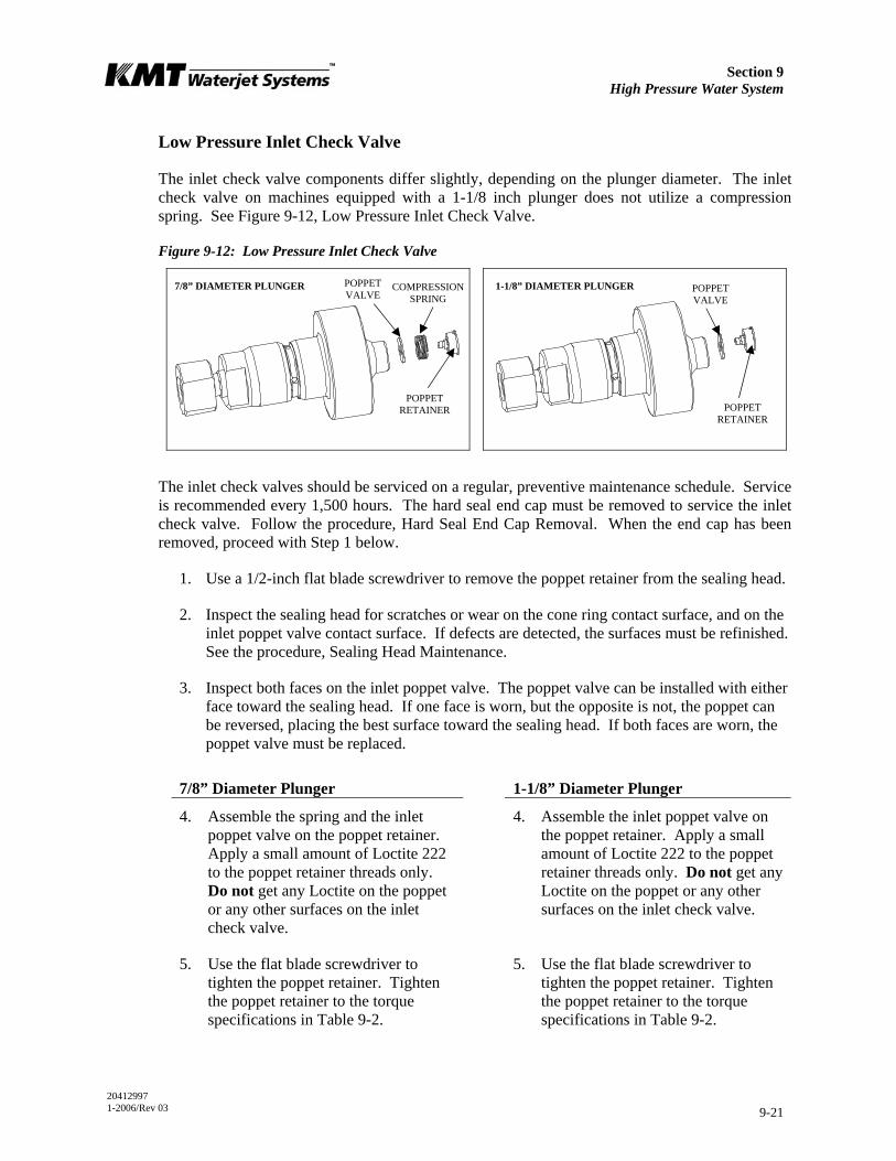
Section 9 High Pressure Water System
20412997 1-2006/Rev 03 9-21
Low Pressure Inlet Check Valve
The inlet check valve components differ slightly, depending on the plunger diameter. The inlet check valve on machines equipped with a 1-1/8 inch plunger does not utilize a compression spring. See Figure 9-12, Low Pressure Inlet Check Valve.
Figure 9-12: Low Pressure Inlet Check Valve
The inlet check valves should be serviced on a regular, preventive maintenance schedule. Service is recommended every 1,500 hours. The hard seal end cap must be removed to service the inlet check valve. Follow the procedure, Hard Seal End Cap Removal. When the end cap has been removed, proceed with Step 1 below.
1. Use a 1/2-inch flat blade screwdriver to remove the poppet retainer from the sealing head.
2. Inspect the sealing head for scratches or wear on the cone ring contact surface, and on the inlet poppet valve contact surface. If defects are detected, the surfaces must be refinished. See the procedure, Sealing Head Maintenance.
3. Inspect both faces on the inlet poppet valve. The poppet valve can be installed with either face toward the sealing head. If one face is worn, but the opposite is not, the poppet can be reversed, placing the best surface toward the sealing head. If both faces are worn, the poppet valve must be replaced.
7/8” Diameter Plunger 1-1/8” Diameter Plunger
4. Assemble the spring and the inlet poppet valve on the poppet retainer. Apply a small amount of Loctite 222 to the poppet retainer threads only. Do not get any Loctite on the poppet or any other surfaces on the inlet check valve.
4. Assemble the inlet poppet valve on the poppet retainer. Apply a small amount of Loctite 222 to the poppet retainer threads only. Do not get any Loctite on the poppet or any other surfaces on the inlet check valve.
5. Use the flat blade screwdriver to tighten the poppet retainer. Tighten the poppet retainer to the torque specifications in Table 9-2.
5. Use the flat blade screwdriver to tighten the poppet retainer. Tighten the poppet retainer to the torque specifications in Table 9-2.
POPPET VALVE
POPPET VALVE
POPPET RETAINER
POPPET RETAINER
COMPRESSION SPRING
7/8” DIAMETER PLUNGER 1-1/8” DIAMETER PLUNGER
Section 9 High Pressure Water System
20412997 1-2006/Rev 03 9-22
6. Inspect the assembled unit to ensure:
• The poppet moves freely
• The spring is fully guided on the poppet retainer
• The spring end is 90 degrees from the screwdriver slot on the retainer
• The poppet retainer is seated against the sealing head
6. Inspect the assembled unit to ensure:
• The poppet moves freely
• The poppet retainer is seated against the sealing head
Sealing Head Maintenance
The sealing head should be inspected for scratches, excessive sealing damage or erosion marking on the cone ring contact surface, and on the inlet poppet valve contact surface. If defects are detected, the surfaces must be refinished. The sealing head can be returned to KMT Waterjet for refinishing.
1. Clean the 45-degree surface on the cone ring with 600-grit wet/dry sandpaper, using a radial motion. It will not be possible to fully remove the main sealing marks.
2. Inspect the inlet poppet valve sealing surface for pits, scratches or jetting erosion. If necessary, refinish the surface.
Place a piece of 1/4-1/2” thick plate glass, not window glass, on a sturdy table to provide an absolutely flat surface. Place a piece of 400-grit wet/dry sandpaper on the glass. Use even, deliberate strokes, rotating the sealing head approximately 10-15 degrees after each stroke. Polish the sealing head until it is flat and smooth. Be careful not to cause additional damage by tilting or tipping the part while polishing.
3. When the sealing head is flat and smooth, perform a final polish with 600-grit wet/dry sandpaper.
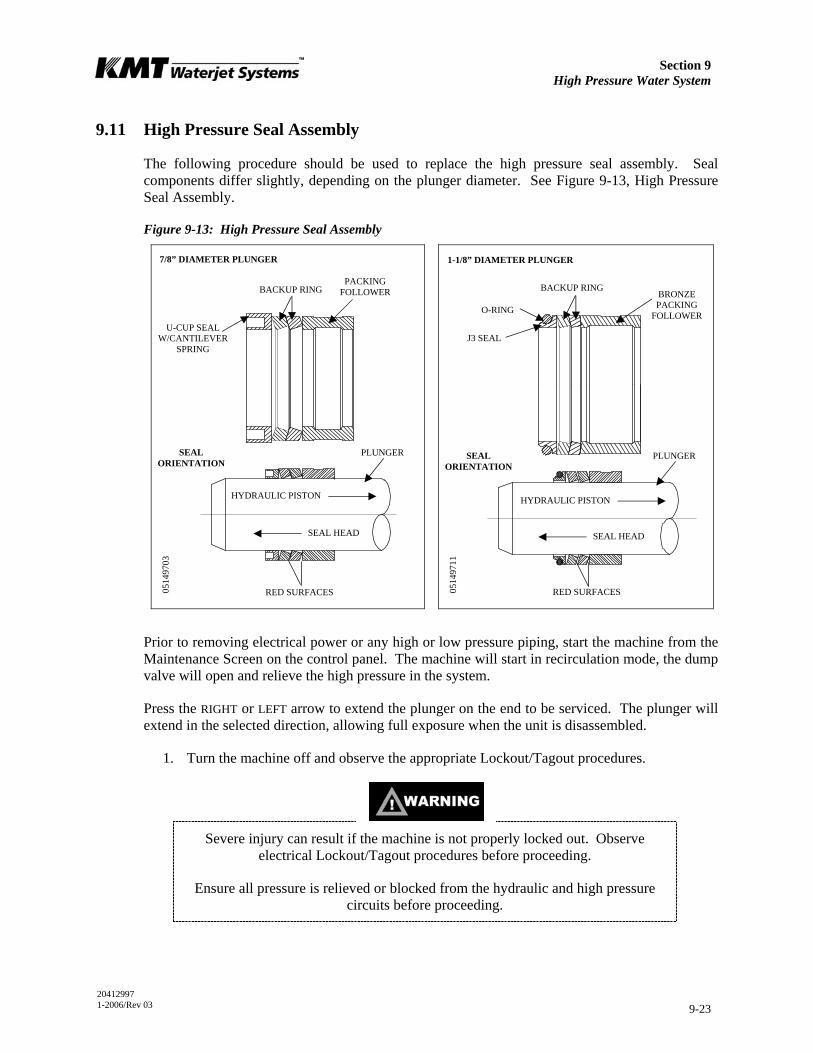
Section 9 High Pressure Water System
20412997 1-2006/Rev 03 9-23
9.11 High Pressure Seal Assembly
The following procedure should be used to replace the high pressure seal assembly. Seal components differ slightly, depending on the plunger diameter. See Figure 9-13, High Pressure Seal Assembly.
Figure 9-13: High Pressure Seal Assembly
Prior to removing electrical power or any high or low pressure piping, start the machine from the Maintenance Screen on the control panel. The machine will start in recirculation mode, the dump valve will open and relieve the high pressure in the system.
Press the RIGHT or LEFT arrow to extend the plunger on the end to be serviced. The plunger will extend in the selected direction, allowing full exposure when the unit is disassembled.
1. Turn the machine off and observe the appropriate Lockout/Tagout procedures.
Severe injury can result if the machine is not properly locked out. Observe electrical Lockout/Tagout procedures before proceeding.
Ensure all pressure is relieved or blocked from the hydraulic and high pressure circuits before proceeding.
SEAL HEAD
HYDRAULIC PISTON
PLUNGER
RED SURFACES
PACKING FOLLOWER BACKUP RING
U-CUP SEAL W/CANTILEVER
SPRING
7/8” DIAMETER PLUNGER
SEAL ORIENTATION
1-1/8” DIAMETER PLUNGER
BACKUP RING BRONZE PACKING
FOLLOWER
RED SURFACES
HYDRAULIC PISTON
SEAL HEAD
PLUNGER SEAL ORIENTATION
O-RING
J3 SEAL
0514
9703
0514
9711
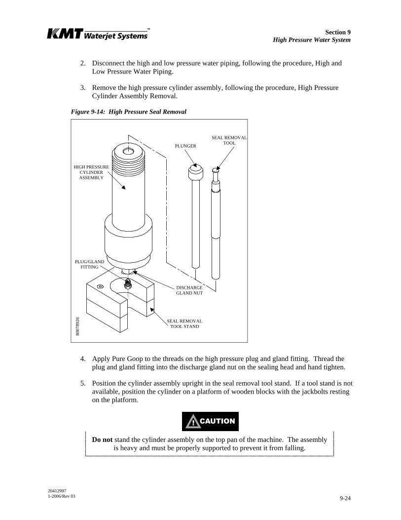
Section 9 High Pressure Water System
20412997 1-2006/Rev 03 9-24
2. Disconnect the high and low pressure water piping, following the procedure, High and Low Pressure Water Piping.
3. Remove the high pressure cylinder assembly, following the procedure, High Pressure Cylinder Assembly Removal.
Figure 9-14: High Pressure Seal Removal
4. Apply Pure Goop to the threads on the high pressure plug and gland fitting. Thread the plug and gland fitting into the discharge gland nut on the sealing head and hand tighten.
5. Position the cylinder assembly upright in the seal removal tool stand. If a tool stand is not available, position the cylinder on a platform of wooden blocks with the jackbolts resting on the platform.
Do not stand the cylinder assembly on the top pan of the machine. The assembly is heavy and must be properly supported to prevent it from falling.
HIGH PRESSURE CYLINDER ASSEMBLY
PLUG/GLAND FITTING
SEAL REMOVAL TOOL STAND
PLUNGER
SEAL REMOVAL TOOL
DISCHARGE GLAND NUT
8007
8926

Section 9 High Pressure Water System
20412997 1-2006/Rev 03 9-25
6. Fill the cylinder with water and slide the seal removal tool or a used plunger into the bronze packing follower to ensure a good seal for the removal of the seal assembly.
7. Place a shop towel around the plunger or seal removal tool to avoid splash back. Use a dead blow hammer to drive the removal tool or plunger into the cylinder until the seal components move up and out of the cylinder.
8. Remove the cylinder liner from the bore and inspect for possible heat or wear damage, or for debris. If cracks or brittleness are detected on the tabs on the ends of the liner, the liner must be replaced.
9. Feel approximately one inch into the cylinder bore for obvious ridges or grooves. If seal debris is present, follow the procedure, High Pressure Cylinder Maintenance.
10. Inspect the plunger surface for flaws. Rotate the plunger 360 degrees by hand while viewing light reflection on the surface to detect any dullness, streaks, pits or other defects. Run a fingernail perpendicular to the direction of the suspected flaws to determine the severity of defects. Depending on the seal life achieved with the removed seal assembly, make a judgment regarding plunger and/or cylinder replacement. If seal debris is present on the plunger, polish with 600-grit wet/dry sandpaper, using a radial motion.
11. Lightly coat the new seal components with FML-2 grease and install the new components on the plunger. Ensure the proper orientation of the backup rings as illustrated in Figure 9-14, High Pressure Seal Assembly.
If applicable, the cantilever spring inside the u-cup seal for the 7/8-inch plunger can easily be distorted. Verify that the spring, lips and cavity appear uniform prior to installation.
12. Slide the cylinder liner over the plunger.
13. Install the high pressure cylinder assembly into the hydraulic cylinder head, following the procedure, High Pressure Cylinder Assembly Installation.
14. Reconnect the high and low pressure water piping and turn the low pressure water supply on.
9.12 Hydraulic Cartridge Seal and Plunger Removal
The following procedure is used to remove the hydraulic cartridge seal and the plunger.
Prior to removing electrical power or any high or low pressure piping, start the machine from the Maintenance Screen on the control panel. The machine will start in recirculation mode, the dump valve will open and relieve the high pressure in the system.
Press the RIGHT or LEFT arrow to extend the plunger on the end to be serviced. The plunger will extend in the selected direction, allowing full exposure when the unit is disassembled.
1. Turn the machine off and observe the appropriate Lockout/Tagout procedures.
Section 9 High Pressure Water System
20412997 1-2006/Rev 03 9-26
Severe injury can result if the machine is not properly locked out. Observe electrical Lockout/Tagout procedures before proceeding.
Ensure all pressure is relieved or blocked from the hydraulic and high pressure circuits before proceeding.
2. Disconnect the high and low pressure water piping, following the procedure, High and Low Pressure Water Piping.
3. Remove the proximity switch on the end of the hydraulic cylinder to be serviced. This will allow the hydraulic oil to drain back to the reservoir, minimizing oil spillage. It will take approximately five minutes for the oil to drain.
4. Remove the high pressure cylinder assembly, following the procedure, High Pressure Cylinder Assembly Removal.
5. Use a flat screwdriver to remove the retaining ring from the hydraulic cylinder head.
6. Remove the bushing retainer flange and clean the surfaces, weep holes and grooves. Check the retainer flange for cracks.
7. Replace the proximity switch by positioning the o-ring spacer and the switch. Apply JL-M grease to the threads on the socket head screws and tighten, following the torque specifications in Table 9-2.
It is recommended that the proximity switch be reinstalled as soon as practical. Removal of the switch presents the potential of an oil spray hazard.
Ensure that the proximity switch is properly installed and secured prior to starting the machine. Failure to tighten the two hold down screws on each switch will
result in the spray of hydraulic oil.
8. Thread the large end of the plunger removal tool onto the hydraulic cartridge seal and pull the cartridge out, over the plunger.
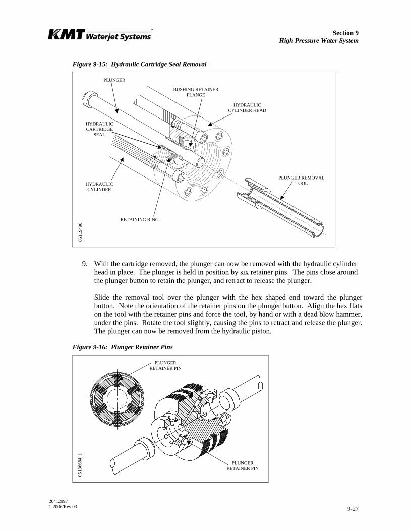
Section 9 High Pressure Water System
20412997 1-2006/Rev 03 9-27
Figure 9-15: Hydraulic Cartridge Seal Removal
9. With the cartridge removed, the plunger can now be removed with the hydraulic cylinder head in place. The plunger is held in position by six retainer pins. The pins close around the plunger button to retain the plunger, and retract to release the plunger.
Slide the removal tool over the plunger with the hex shaped end toward the plunger button. Note the orientation of the retainer pins on the plunger button. Align the hex flats on the tool with the retainer pins and force the tool, by hand or with a dead blow hammer, under the pins. Rotate the tool slightly, causing the pins to retract and release the plunger. The plunger can now be removed from the hydraulic piston.
Figure 9-16: Plunger Retainer Pins
PLUNGER REMOVAL TOOL HYDRAULIC
CYLINDER
HYDRAULIC CYLINDER HEAD
BUSHING RETAINER FLANGE
PLUNGER
RETAINING RING
HYDRAULIC CARTRIDGE
SEAL
0511
9490
PLUNGER RETAINER PIN
PLUNGER RETAINER PIN
0513
6684
_1
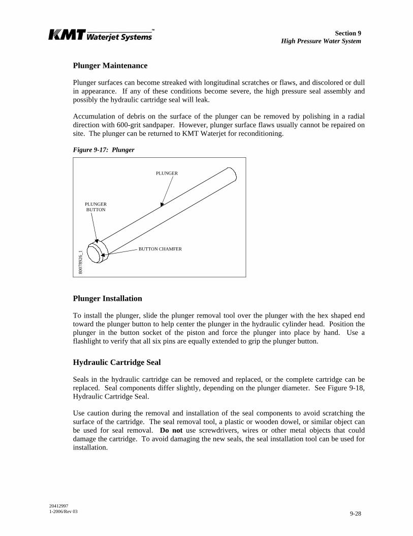
Section 9 High Pressure Water System
20412997 1-2006/Rev 03 9-28
Plunger Maintenance
Plunger surfaces can become streaked with longitudinal scratches or flaws, and discolored or dull in appearance. If any of these conditions become severe, the high pressure seal assembly and possibly the hydraulic cartridge seal will leak.
Accumulation of debris on the surface of the plunger can be removed by polishing in a radial direction with 600-grit sandpaper. However, plunger surface flaws usually cannot be repaired on site. The plunger can be returned to KMT Waterjet for reconditioning.
Figure 9-17: Plunger
Plunger Installation
To install the plunger, slide the plunger removal tool over the plunger with the hex shaped end toward the plunger button to help center the plunger in the hydraulic cylinder head. Position the plunger in the button socket of the piston and force the plunger into place by hand. Use a flashlight to verify that all six pins are equally extended to grip the plunger button.
Hydraulic Cartridge Seal
Seals in the hydraulic cartridge can be removed and replaced, or the complete cartridge can be replaced. Seal components differ slightly, depending on the plunger diameter. See Figure 9-18, Hydraulic Cartridge Seal.
Use caution during the removal and installation of the seal components to avoid scratching the surface of the cartridge. The seal removal tool, a plastic or wooden dowel, or similar object can be used for seal removal. Do not use screwdrivers, wires or other metal objects that could damage the cartridge. To avoid damaging the new seals, the seal installation tool can be used for installation.
PLUNGER
BUTTON CHAMFER
PLUNGER BUTTON
8007
8926
_1
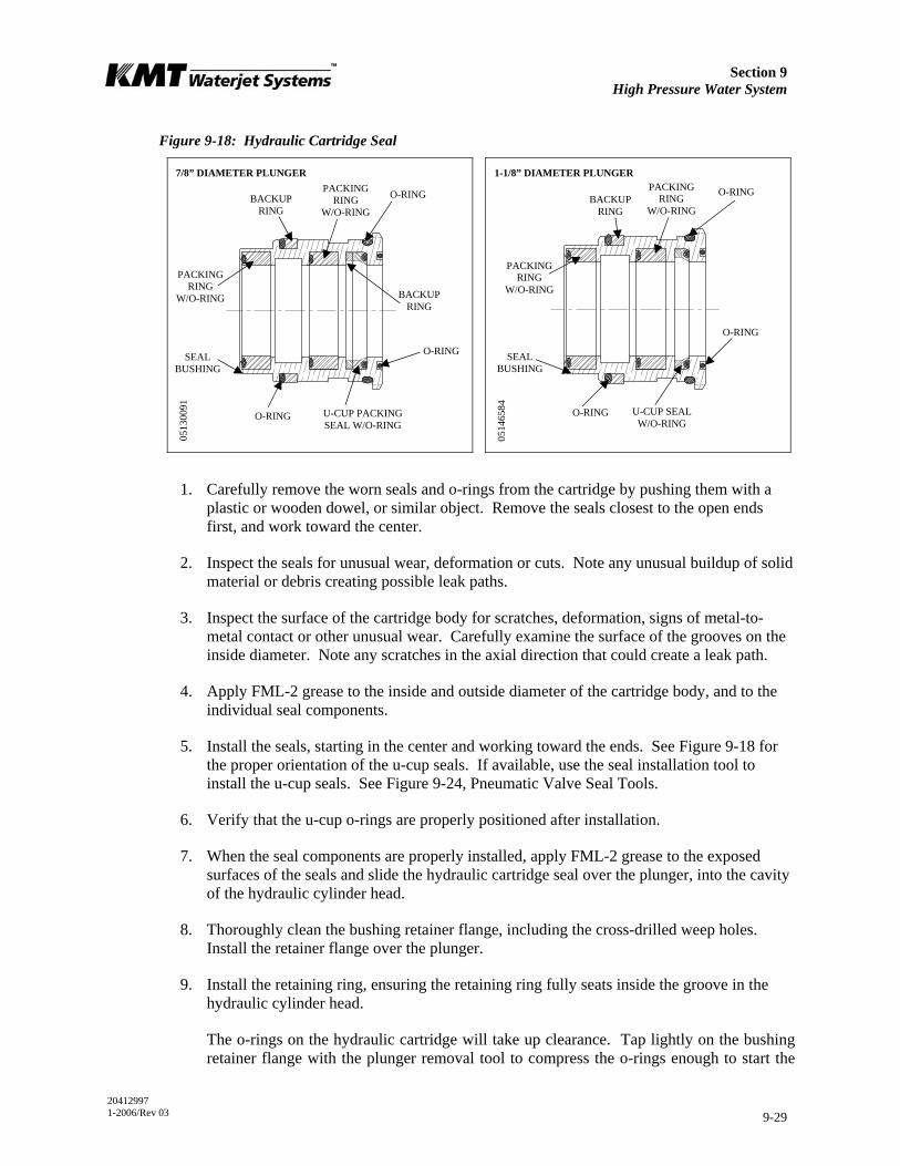
Section 9 High Pressure Water System
20412997 1-2006/Rev 03 9-29
Figure 9-18: Hydraulic Cartridge Seal
1. Carefully remove the worn seals and o-rings from the cartridge by pushing them with a plastic or wooden dowel, or similar object. Remove the seals closest to the open ends first, and work toward the center.
2. Inspect the seals for unusual wear, deformation or cuts. Note any unusual buildup of solid material or debris creating possible leak paths.
3. Inspect the surface of the cartridge body for scratches, deformation, signs of metal-to-metal contact or other unusual wear. Carefully examine the surface of the grooves on the inside diameter. Note any scratches in the axial direction that could create a leak path.
4. Apply FML-2 grease to the inside and outside diameter of the cartridge body, and to the individual seal components.
5. Install the seals, starting in the center and working toward the ends. See Figure 9-18 for the proper orientation of the u-cup seals. If available, use the seal installation tool to install the u-cup seals. See Figure 9-24, Pneumatic Valve Seal Tools.
6. Verify that the u-cup o-rings are properly positioned after installation.
7. When the seal components are properly installed, apply FML-2 grease to the exposed surfaces of the seals and slide the hydraulic cartridge seal over the plunger, into the cavity of the hydraulic cylinder head.
8. Thoroughly clean the bushing retainer flange, including the cross-drilled weep holes. Install the retainer flange over the plunger.
9. Install the retaining ring, ensuring the retaining ring fully seats inside the groove in the hydraulic cylinder head.
The o-rings on the hydraulic cartridge will take up clearance. Tap lightly on the bushing retainer flange with the plunger removal tool to compress the o-rings enough to start the
U-CUP PACKINGSEAL W/O-RING
O-RING
PACKING RING
W/O-RING
PACKINGRING
W/O-RING
SEAL BUSHING
BACKUP RING
O-RING
O-RING PACKING RING
W/O-RING
BACKUPRING
O-RING PACKING RING
W/O-RING BACKUP
RING
SEAL BUSHING
O-RING
O-RING
U-CUP SEAL W/O-RING
7/8” DIAMETER PLUNGER 1-1/8” DIAMETER PLUNGER 05
1300
91
0514
6584

Section 9 High Pressure Water System
20412997 1-2006/Rev 03 9-30
retaining ring in the groove. Use a flat blade screwdriver to push on the outer edge of the retainer flange while working one end of the retaining ring into the groove. The retainer flange should tilt or tip enough to allow the retaining ring to move into the groove. Continue working the ring into the groove while tilting the retainer flange until the ring is fully seated.
10. Install the high pressure cylinder assembly into the hydraulic cylinder head, following the procedure, High Pressure Cylinder Assembly Installation.
11. Connect the high and low pressure water piping and turn the low pressure water supply on.

Section 9 High Pressure Water System
20412997 1-2006/Rev 03 9-31
9.13 Hydraulic Piston
Two bearing rings provide wear contact between the piston and the inside diameter of the hydraulic cylinder. On each end of the piston, six retainer pins hold the plunger in position. The plunger retainer pins are held in place by a flat snap ring. Two internal check valves vent unwanted hydraulic pressure from one side of the piston to the other, preventing pressure from building behind the plunger button.
Figure 9-19: Hydraulic Piston Components
Hydraulic Piston Removal
The following procedure is used to remove the hydraulic piston.
1. Turn the machine off and observe the appropriate Lockout/Tagout procedures.
SET SCREW
O-RING CHECK VALVE
PLUNGER RETAINER PIN
PISTON SEAL ASSEMBLY
BEARING RING FLAT SNAP RING
PISTON
O-RING
BACKUP RING
PLUNGER RETAINER PIN
BEARING RING
0513
6684
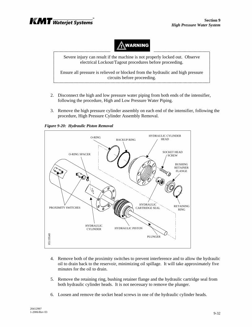
Section 9 High Pressure Water System
20412997 1-2006/Rev 03 9-32
Severe injury can result if the machine is not properly locked out. Observe electrical Lockout/Tagout procedures before proceeding.
Ensure all pressure is relieved or blocked from the hydraulic and high pressure circuits before proceeding.
2. Disconnect the high and low pressure water piping from both ends of the intensifier, following the procedure, High and Low Pressure Water Piping.
3. Remove the high pressure cylinder assembly on each end of the intensifier, following the procedure, High Pressure Cylinder Assembly Removal.
Figure 9-20: Hydraulic Piston Removal
4. Remove both of the proximity switches to prevent interference and to allow the hydraulic oil to drain back to the reservoir, minimizing oil spillage. It will take approximately five minutes for the oil to drain.
5. Remove the retaining ring, bushing retainer flange and the hydraulic cartridge seal from both hydraulic cylinder heads. It is not necessary to remove the plunger.
6. Loosen and remove the socket head screws in one of the hydraulic cylinder heads.
HYDRAULIC CARTRIDGE SEAL
SOCKET HEAD SCREW
HYDRAULIC CYLINDER HEAD O-RING
BACKUP RING
O-RING SPACER
HYDRAULIC CYLINDER
PROXIMITY SWITCHES
BUSHING RETAINER FLANGE
RETAINING RING
HYDRAULIC PISTON
PLUNGER
0511
9540

Section 9 High Pressure Water System
20412997 1-2006/Rev 03 9-33
7. Remove the hydraulic cylinder head with the o-ring and backup ring. The mounting flat for the proximity switch provides a small lip for loosening the cylinder head.
8. Grasp the plunger firmly and pull the piston out of the hydraulic cylinder.
Bearing Rings and Seal Assembly
1. Remove the plungers.
2. Use a smooth, dull-edged blade made from brass or similar soft metal material to remove the two bearing rings and the seal assembly.
NOTE
Do not scratch the surfaces of the piston seal groove. Scratches on the sides or bottom of the groove can result in hydraulic leaks.
3. Inspect the bottom of the seal grooves for marks, scratches and residue buildup. Clean and/or repair the groove surfaces as required.
4. Apply FML-2 grease to the new bearing rings and install the rings.
5. The piston seal assembly consists of an inner and an outer seal ring. Apply FML-2 grease to both rings. Use the smooth, dull-edged blade to install the inner ring, ensuring the ring is not twisted after installation. Slide the outer seal ring over the metal edges and ease it into position over the inner ring.
Figure 9-21: Hydraulic Piston
PLUNGER RETAINER PIN
FLAT SNAP RING
OUTER SEAL RING INNER SEAL RING
SET SCREW
CHECK VALVE
O-RING
BEARING RING
PLUNGER BUTTON O-RING
PLUNGER BUTTON BACKUP RING
0513
2253
_1
Section 9 High Pressure Water System
20412997 1-2006/Rev 03 9-34
Plunger Button Sockets, Seals and Retainer Pins
1. Remove the flat snap rings and plunger retainer pins on both ends of the piston.
2. Inspect the snap rings and the pins for unusual wear or deformation. Clean and inspect the pin holes for unusual wear, deformation or hole enlargement.
3. Remove the plunger button o-ring and backup ring from each plunger socket. Take care not to scratch or damage the seal groove surfaces.
4. Clean and inspect the seal grooves for residue buildup or surface marks that could cause seal leaks.
5. Inspect the plunger button sockets for unusual wear.
NOTE
Due to the high contact force between the piston and the plunger, the plunger may make an impression in the bottom of the socket. This compression mark or
indentation is normal.
6. Apply FML-2 grease to new plunger button backup rings and o-rings. Install the rings in the internal groove in the plunger socket. If the backup ring is not installed the plunger can be forced out of the plunger socket.
7. Install the retainer pins, verifying that each pin moves freely without excess side play in the pin holes.
8. Install the flat snap ring over the pins.
9. Install the plungers and check the snap-in feature of the plunger attachment. Use the plunger removal tool to ensure the pins retract to release the plunger, and close to retain the plunger in a uniform manner.
Internal Check Valves
It is not necessary to service the internal check valves unless a problem is suspected. If the check valves or the internal passages in the piston require service, plunger button, seal and pin servicing is also recommended. See Figure 9-21, Hydraulic Piston.
1. Loosen the set screw and remove the check valves and o-rings. Clean the internal passages.
2. Apply FML-2 grease to a new o-ring and install the new o-ring in the check valve passage. Use a blunt, pencil-like instrument to position it in the bottom of the passage.
3. Clean and install a new check valve with the chamfered end toward the o-ring.
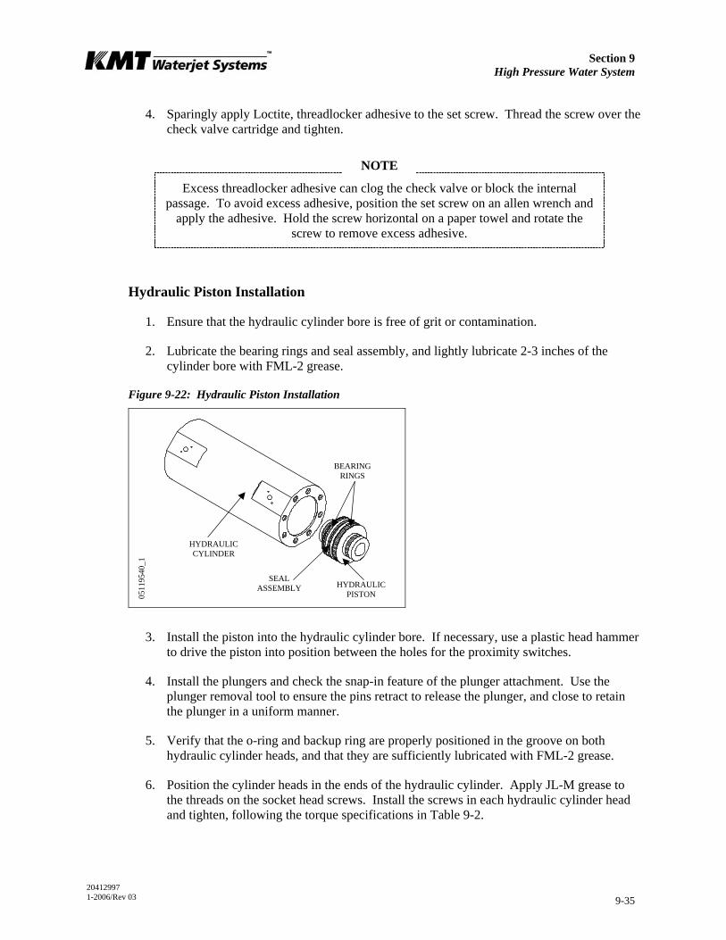
Section 9 High Pressure Water System
20412997 1-2006/Rev 03 9-35
4. Sparingly apply Loctite, threadlocker adhesive to the set screw. Thread the screw over the check valve cartridge and tighten.
NOTE
Excess threadlocker adhesive can clog the check valve or block the internal passage. To avoid excess adhesive, position the set screw on an allen wrench and
apply the adhesive. Hold the screw horizontal on a paper towel and rotate the screw to remove excess adhesive.
Hydraulic Piston Installation
1. Ensure that the hydraulic cylinder bore is free of grit or contamination.
2. Lubricate the bearing rings and seal assembly, and lightly lubricate 2-3 inches of the cylinder bore with FML-2 grease.
Figure 9-22: Hydraulic Piston Installation
3. Install the piston into the hydraulic cylinder bore. If necessary, use a plastic head hammer to drive the piston into position between the holes for the proximity switches.
4. Install the plungers and check the snap-in feature of the plunger attachment. Use the plunger removal tool to ensure the pins retract to release the plunger, and close to retain the plunger in a uniform manner.
5. Verify that the o-ring and backup ring are properly positioned in the groove on both hydraulic cylinder heads, and that they are sufficiently lubricated with FML-2 grease.
6. Position the cylinder heads in the ends of the hydraulic cylinder. Apply JL-M grease to the threads on the socket head screws. Install the screws in each hydraulic cylinder head and tighten, following the torque specifications in Table 9-2.
HYDRAULIC PISTON
HYDRAULIC CYLINDER
0511
9540
_1
BEARING RINGS
SEAL ASSEMBLY
Section 9 High Pressure Water System
20412997 1-2006/Rev 03 9-36
7. Replace the hydraulic cartridge seal, bushing retainer flange and retaining ring in both hydraulic cylinder heads.
8. Replace the proximity switches by positioning the o-ring spacers and the switches. Apply JL-M grease to the threads on the socket head screws and tighten, following the torque specifications in Table 9-2.
Ensure that the proximity switches are properly installed and secured prior to starting the motor. Failure to tighten the two hold down screws on each switch
will result in the spray of hydraulic oil.
9. Install the high pressure cylinder assemblies into the hydraulic cylinder heads, following the procedure, High Pressure Cylinder Assembly Installation.
10. Connect the high and low pressure water piping. And turn the low pressure water supply on.
9.14 Hydraulic Cylinder Maintenance
The inside diameter surface of the hydraulic cylinder should be inspected for wear grooves and surface finish whenever the hydraulic cylinder heads are removed. Excessive grooving is indicative of piston seal wear.
9.15 High Pressure Attenuator
The high pressure attenuator is not serviceable at the customer level. KMT Waterjet Systems tests the seals in the attenuator at pressures exceeding normal operating pressure, making disassembly difficult. If the attenuator develops a high pressure water leak, it should be replaced.
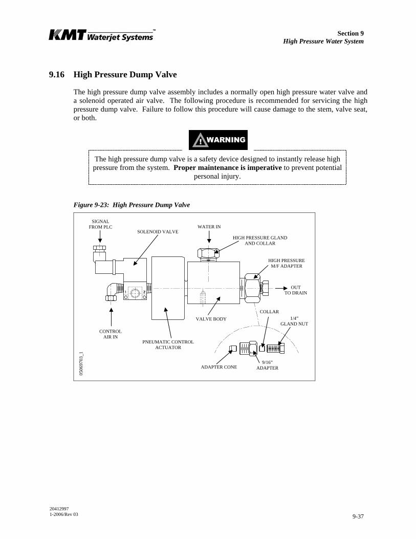
Section 9 High Pressure Water System
20412997 1-2006/Rev 03 9-37
9.16 High Pressure Dump Valve
The high pressure dump valve assembly includes a normally open high pressure water valve and a solenoid operated air valve. The following procedure is recommended for servicing the high pressure dump valve. Failure to follow this procedure will cause damage to the stem, valve seat, or both.
The high pressure dump valve is a safety device designed to instantly release high pressure from the system. Proper maintenance is imperative to prevent potential
personal injury.
Figure 9-23: High Pressure Dump Valve
ADAPTER CONE
WATER IN
HIGH PRESSURE GLAND AND COLLAR
SIGNAL FROM PLC
SOLENOID VALVE
PNEUMATIC CONTROL ACTUATOR
CONTROL AIR IN
1/4” GLAND NUT
9/16” ADAPTER
OUT TO DRAIN
HIGH PRESSURE M/F ADAPTER
VALVE BODY COLLAR
0506
9703
_1
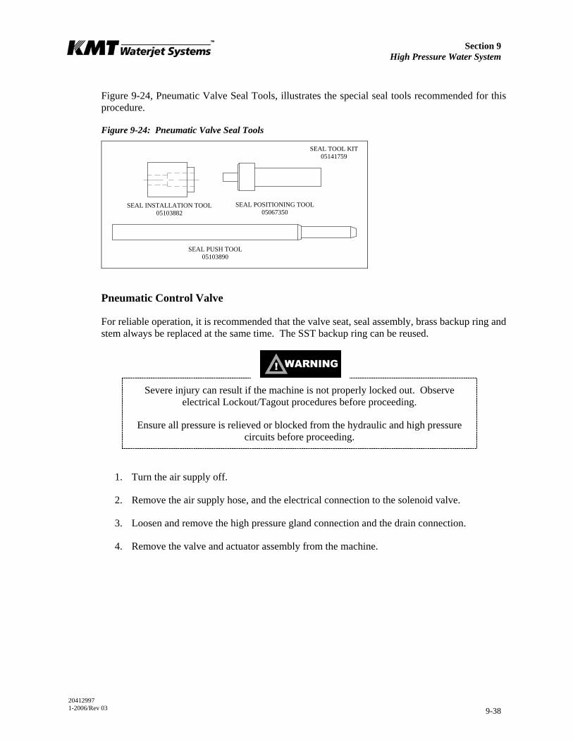
Section 9 High Pressure Water System
20412997 1-2006/Rev 03 9-38
Figure 9-24, Pneumatic Valve Seal Tools, illustrates the special seal tools recommended for this procedure.
Figure 9-24: Pneumatic Valve Seal Tools
Pneumatic Control Valve
For reliable operation, it is recommended that the valve seat, seal assembly, brass backup ring and stem always be replaced at the same time. The SST backup ring can be reused.
Severe injury can result if the machine is not properly locked out. Observe electrical Lockout/Tagout procedures before proceeding.
Ensure all pressure is relieved or blocked from the hydraulic and high pressure circuits before proceeding.
1. Turn the air supply off.
2. Remove the air supply hose, and the electrical connection to the solenoid valve.
3. Loosen and remove the high pressure gland connection and the drain connection.
4. Remove the valve and actuator assembly from the machine.
SEAL INSTALLATION TOOL 05103882
SEAL PUSH TOOL 05103890
SEAL POSITIONING TOOL 05067350
SEAL TOOL KIT 05141759
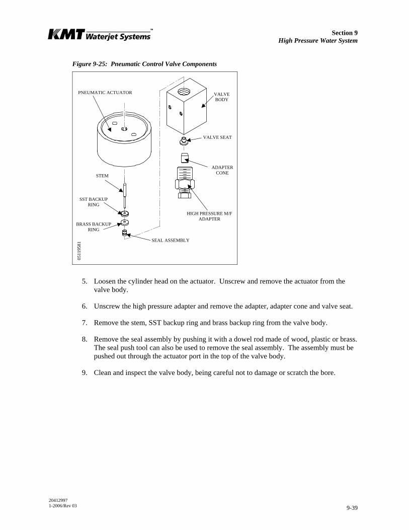
Section 9 High Pressure Water System
20412997 1-2006/Rev 03 9-39
Figure 9-25: Pneumatic Control Valve Components
5. Loosen the cylinder head on the actuator. Unscrew and remove the actuator from the valve body.
6. Unscrew the high pressure adapter and remove the adapter, adapter cone and valve seat.
7. Remove the stem, SST backup ring and brass backup ring from the valve body.
8. Remove the seal assembly by pushing it with a dowel rod made of wood, plastic or brass. The seal push tool can also be used to remove the seal assembly. The assembly must be pushed out through the actuator port in the top of the valve body.
9. Clean and inspect the valve body, being careful not to damage or scratch the bore.
STEM
HIGH PRESSURE M/F ADAPTER
ADAPTER CONE
VALVE SEAT
VALVE BODY
PNEUMATIC ACTUATOR
SST BACKUP RING
BRASS BACKUP RING
SEAL ASSEMBLY
0511
9581
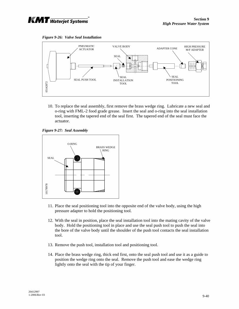
Section 9 High Pressure Water System
20412997 1-2006/Rev 03 9-40
Figure 9-26: Valve Seal Installation
10. To replace the seal assembly, first remove the brass wedge ring. Lubricate a new seal and o-ring with FML-2 food grade grease. Insert the seal and o-ring into the seal installation tool, inserting the tapered end of the seal first. The tapered end of the seal must face the actuator.
Figure 9-27: Seal Assembly
11. Place the seal positioning tool into the opposite end of the valve body, using the high pressure adapter to hold the positioning tool.
12. With the seal in position, place the seal installation tool into the mating cavity of the valve body. Hold the positioning tool in place and use the seal push tool to push the seal into the bore of the valve body until the shoulder of the push tool contacts the seal installation tool.
13. Remove the push tool, installation tool and positioning tool.
14. Place the brass wedge ring, thick end first, onto the seal push tool and use it as a guide to position the wedge ring onto the seal. Remove the push tool and ease the wedge ring lightly onto the seal with the tip of your finger.
VALVE BODY
SEAL INSTALLATION
TOOL
PNEUMATIC ACTUATOR
SEAL PUSH TOOL
HIGH PRESSURE M/F ADAPTER ADAPTER CONE
SEAL POSITIONING
TOOL
SEAL
0514
2872
O-RING BRASS WEDGE
RING
SEAL
1017
8978
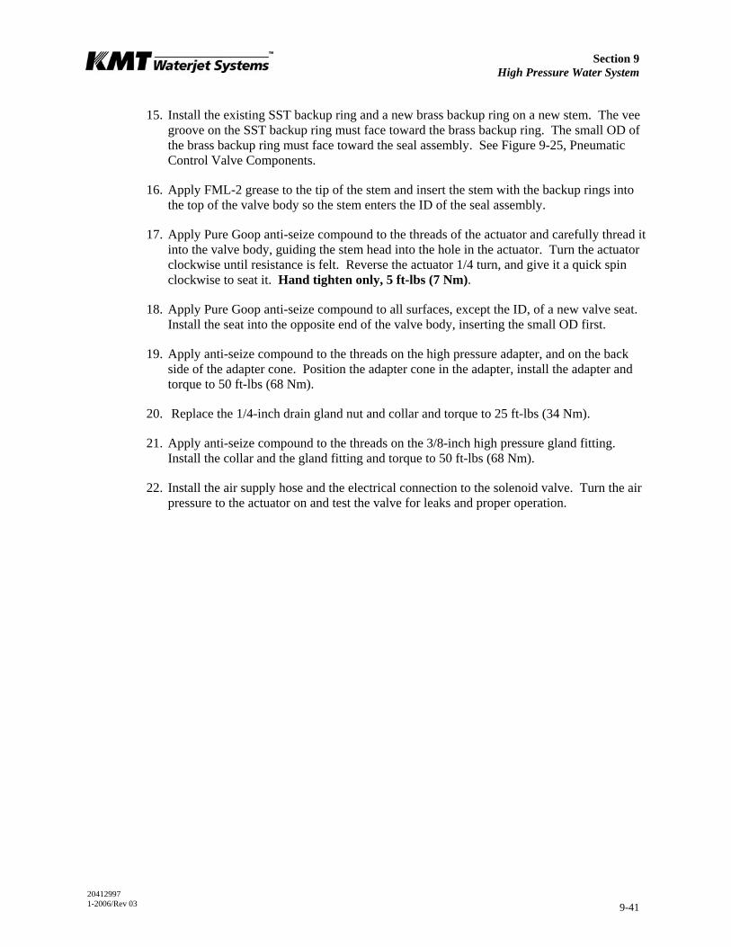
Section 9 High Pressure Water System
20412997 1-2006/Rev 03 9-41
15. Install the existing SST backup ring and a new brass backup ring on a new stem. The vee groove on the SST backup ring must face toward the brass backup ring. The small OD of the brass backup ring must face toward the seal assembly. See Figure 9-25, Pneumatic Control Valve Components.
16. Apply FML-2 grease to the tip of the stem and insert the stem with the backup rings into the top of the valve body so the stem enters the ID of the seal assembly.
17. Apply Pure Goop anti-seize compound to the threads of the actuator and carefully thread it into the valve body, guiding the stem head into the hole in the actuator. Turn the actuator clockwise until resistance is felt. Reverse the actuator 1/4 turn, and give it a quick spin clockwise to seat it. Hand tighten only, 5 ft-lbs (7 Nm).
18. Apply Pure Goop anti-seize compound to all surfaces, except the ID, of a new valve seat. Install the seat into the opposite end of the valve body, inserting the small OD first.
19. Apply anti-seize compound to the threads on the high pressure adapter, and on the back side of the adapter cone. Position the adapter cone in the adapter, install the adapter and torque to 50 ft-lbs (68 Nm).
20. Replace the 1/4-inch drain gland nut and collar and torque to 25 ft-lbs (34 Nm).
21. Apply anti-seize compound to the threads on the 3/8-inch high pressure gland fitting. Install the collar and the gland fitting and torque to 50 ft-lbs (68 Nm).
22. Install the air supply hose and the electrical connection to the solenoid valve. Turn the air pressure to the actuator on and test the valve for leaks and proper operation.
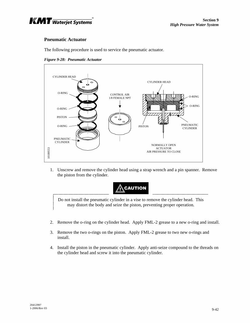
Section 9 High Pressure Water System
20412997 1-2006/Rev 03 9-42
Pneumatic Actuator
The following procedure is used to service the pneumatic actuator.
Figure 9-28: Pneumatic Actuator
1. Unscrew and remove the cylinder head using a strap wrench and a pin spanner. Remove the piston from the cylinder.
Do not install the pneumatic cylinder in a vise to remove the cylinder head. This may distort the body and seize the piston, preventing proper operation.
2. Remove the o-ring on the cylinder head. Apply FML-2 grease to a new o-ring and install.
3. Remove the two o-rings on the piston. Apply FML-2 grease to two new o-rings and install.
4. Install the piston in the pneumatic cylinder. Apply anti-seize compound to the threads on the cylinder head and screw it into the pneumatic cylinder.
NORMALLY OPEN ACTUATOR
AIR PRESSURE TO CLOSE
CONTROL AIR 1/8 FEMALE NPT
CYLINDER HEAD
PISTON
O-RING
PNEUMATIC CYLINDER
O-RING
O-RING
O-RING
O-RING
PNEUMATIC CYLINDER
PISTON
CYLINDER HEAD
1018
9553

Section 9 High Pressure Water System
20412997 1-2006/Rev 03 9-43
9.17 Weep Holes
High pressure seals and connections fail gradually and begin leaking slowly. Weep holes are located at every threaded high pressure connection to provide a vent for internal leaks. Water or oil dripping from a weep hole indicates one or more internal components are beginning to fail.
Table 9-4 lists the location of the weep hole, the possible source of the leak and the corrective action required.
Table 9-4 Weep Holes
High Pressure Water System
Location Indication Comments
Hydraulic Cylinder Head
Hydraulic oil leaking from the weep hole in the hydraulic cylinder head
Failed hydraulic cartridge seal Replace the cartridge seal. If the leak persists, check the plunger for linear scratches or scoring.
Failed high pressure seal assembly
Replace the high pressure seal assembly.
Damaged plunger Check the plunger for longitudinal scratches or flaws. If detected, replace the plunger or return to KMT for evaluation.
Seal material buildup on plunger Polish the plunger surface following the procedure, Plunger Maintenance.
Check for scratches, grooves or material buildup on the inside diameter of the cylinder. If detected, polish the bore following the procedure, High Pressure Cylinder Maintenance.
Water leaking from the weep hole on the hydraulic cylinder head flange
Damaged high pressure cylinder
Check the inside diameter of the cylinder for expansion where the high pressure seal assembly is located. If detected, replace the cylinder.
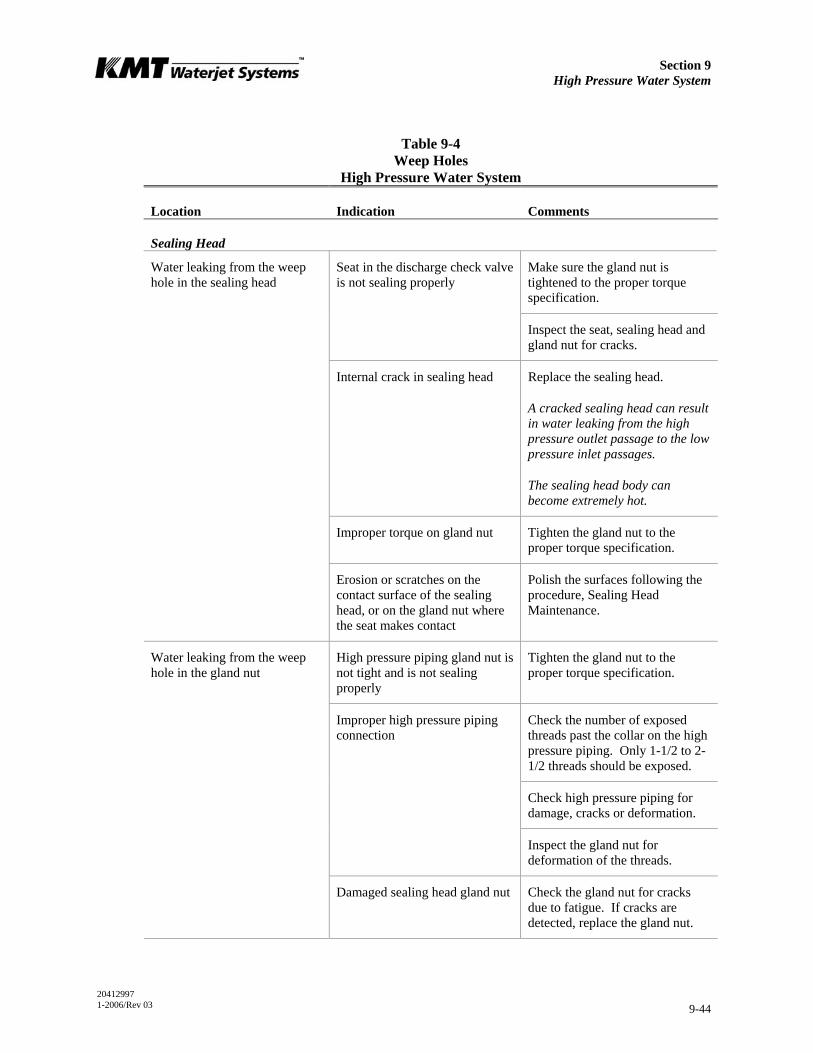
Section 9 High Pressure Water System
20412997 1-2006/Rev 03 9-44
Table 9-4 Weep Holes
High Pressure Water System
Location Indication Comments
Sealing Head
Make sure the gland nut is tightened to the proper torque specification.
Seat in the discharge check valve is not sealing properly
Inspect the seat, sealing head and gland nut for cracks.
Internal crack in sealing head Replace the sealing head.
A cracked sealing head can result in water leaking from the high pressure outlet passage to the low pressure inlet passages.
The sealing head body can become extremely hot.
Improper torque on gland nut Tighten the gland nut to the proper torque specification.
Water leaking from the weep hole in the sealing head
Erosion or scratches on the contact surface of the sealing head, or on the gland nut where the seat makes contact
Polish the surfaces following the procedure, Sealing Head Maintenance.
High pressure piping gland nut is not tight and is not sealing properly
Tighten the gland nut to the proper torque specification.
Check the number of exposed threads past the collar on the high pressure piping. Only 1-1/2 to 2-1/2 threads should be exposed.
Check high pressure piping for damage, cracks or deformation.
Improper high pressure piping connection
Inspect the gland nut for deformation of the threads.
Water leaking from the weep hole in the gland nut
Damaged sealing head gland nut Check the gland nut for cracks due to fatigue. If cracks are detected, replace the gland nut.
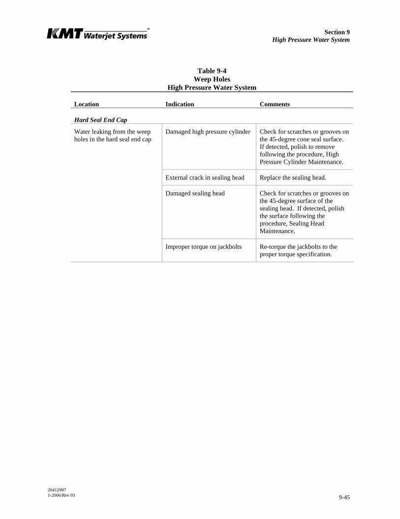
Section 9 High Pressure Water System
20412997 1-2006/Rev 03 9-45
Table 9-4 Weep Holes
High Pressure Water System
Location Indication Comments
Hard Seal End Cap
Damaged high pressure cylinder Check for scratches or grooves on the 45-degree cone seal surface. If detected, polish to remove following the procedure, High Pressure Cylinder Maintenance.
External crack in sealing head Replace the sealing head.
Damaged sealing head Check for scratches or grooves on the 45-degree surface of the sealing head. If detected, polish the surface following the procedure, Sealing Head Maintenance.
Water leaking from the weep holes in the hard seal end cap
Improper torque on jackbolts Re-torque the jackbolts to the proper torque specification.
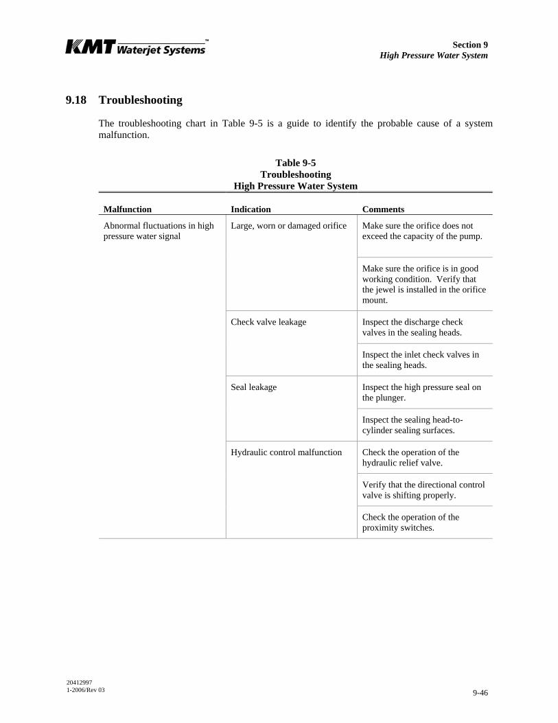
Section 9 High Pressure Water System
20412997 1-2006/Rev 03 9-46
9.18 Troubleshooting
The troubleshooting chart in Table 9-5 is a guide to identify the probable cause of a system malfunction.
Table 9-5 Troubleshooting
High Pressure Water System
Malfunction Indication Comments
Make sure the orifice does not exceed the capacity of the pump.
Large, worn or damaged orifice
Make sure the orifice is in good working condition. Verify that the jewel is installed in the orifice mount.
Inspect the discharge check valves in the sealing heads.
Check valve leakage
Inspect the inlet check valves in the sealing heads.
Inspect the high pressure seal on the plunger.
Seal leakage
Inspect the sealing head-to-cylinder sealing surfaces.
Check the operation of the hydraulic relief valve.
Verify that the directional control valve is shifting properly.
Abnormal fluctuations in high pressure water signal
Hydraulic control malfunction
Check the operation of the proximity switches.

Section 9 High Pressure Water System
20412997 1-2006/Rev 03 9-47
Table 9-5 Troubleshooting
High Pressure Water System
Malfunction Indication Comments
Leaking discharge check valve Inspect the condition of the seat, poppet valve, spring, poppet pin and sealing head surface on the discharge end of the sealing heads.
Leaking inlet check valve Inspect the condition of the poppet valve, poppet retainer and the spring, if applicable, on the inlet end of the sealing heads.
Damaged sealing head Check the cone flange surface of the sealing head for scratches or mechanical damage and replace if necessary.
Hot surfaces on the high pressure cylinder components
Damaged high pressure cylinder Check the high pressure cylinder for cracks.
Restricted water supply Check cutting water supply flow and pressure.
Clogged water filter Check the condition of the low pressure water filter and replace the filter element if necessary.
Low cutting water supply pressure
Trapped air Bleed the air from the cutting water plumbing.
If operating in low pressure, switch to high pressure operation and check the hydraulic pressure setting.
Not applicable when the machine is equipped with the optional proportional pressure control.
Clean the high pressure adjustment valve.
Low hydraulic pressure setting
Clean the compensators on the hydraulic pump.
Low cutting water pressure
Collapsed element in the high pressure line filter
Check the element in the high pressure line filter.
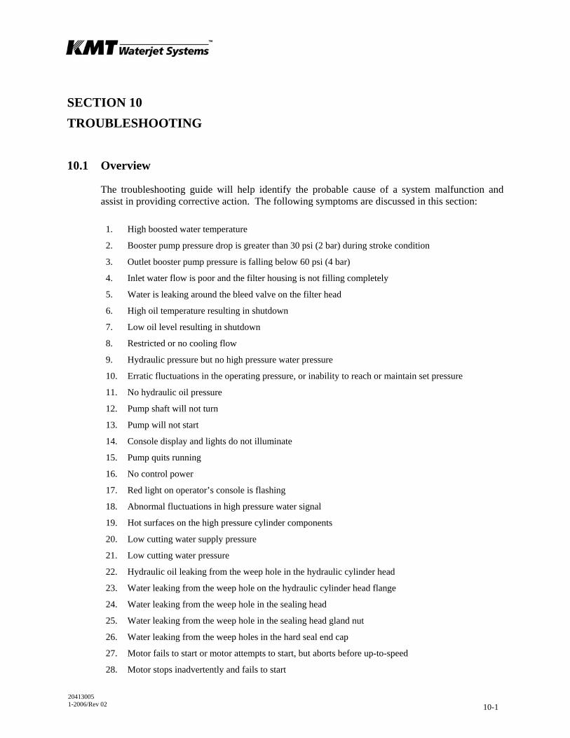
20413005 1-2006/Rev 02 10-1
SECTION 10 TROUBLESHOOTING
10.1 Overview
The troubleshooting guide will help identify the probable cause of a system malfunction and assist in providing corrective action. The following symptoms are discussed in this section:
1. High boosted water temperature
2. Booster pump pressure drop is greater than 30 psi (2 bar) during stroke condition
3. Outlet booster pump pressure is falling below 60 psi (4 bar)
4. Inlet water flow is poor and the filter housing is not filling completely
5. Water is leaking around the bleed valve on the filter head
6. High oil temperature resulting in shutdown
7. Low oil level resulting in shutdown
8. Restricted or no cooling flow
9. Hydraulic pressure but no high pressure water pressure
10. Erratic fluctuations in the operating pressure, or inability to reach or maintain set pressure
11. No hydraulic oil pressure
12. Pump shaft will not turn
13. Pump will not start
14. Console display and lights do not illuminate
15. Pump quits running
16. No control power
17. Red light on operator’s console is flashing
18. Abnormal fluctuations in high pressure water signal
19. Hot surfaces on the high pressure cylinder components
20. Low cutting water supply pressure
21. Low cutting water pressure
22. Hydraulic oil leaking from the weep hole in the hydraulic cylinder head
23. Water leaking from the weep hole on the hydraulic cylinder head flange
24. Water leaking from the weep hole in the sealing head
25. Water leaking from the weep hole in the sealing head gland nut
26. Water leaking from the weep holes in the hard seal end cap
27. Motor fails to start or motor attempts to start, but aborts before up-to-speed
28. Motor stops inadvertently and fails to start
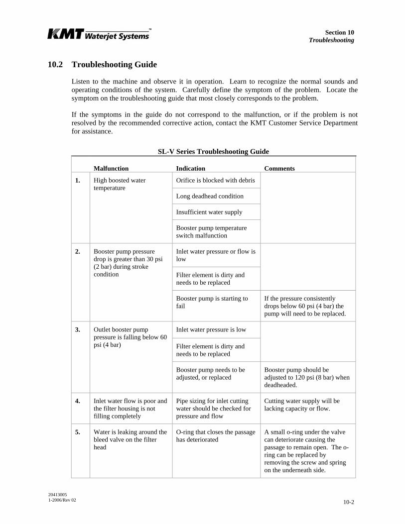
Section 10 Troubleshooting
20413005 1-2006/Rev 02 10-2
10.2 Troubleshooting Guide
Listen to the machine and observe it in operation. Learn to recognize the normal sounds and operating conditions of the system. Carefully define the symptom of the problem. Locate the symptom on the troubleshooting guide that most closely corresponds to the problem.
If the symptoms in the guide do not correspond to the malfunction, or if the problem is not resolved by the recommended corrective action, contact the KMT Customer Service Department for assistance.
SL-V Series Troubleshooting Guide
Malfunction Indication Comments
Orifice is blocked with debris
Long deadhead condition
Insufficient water supply
1. High boosted water temperature
Booster pump temperature switch malfunction
Inlet water pressure or flow is low
Filter element is dirty and needs to be replaced
2. Booster pump pressure drop is greater than 30 psi (2 bar) during stroke condition
Booster pump is starting to fail
If the pressure consistently drops below 60 psi (4 bar) the pump will need to be replaced.
Inlet water pressure is low
Filter element is dirty and needs to be replaced
3. Outlet booster pump pressure is falling below 60 psi (4 bar)
Booster pump needs to be adjusted, or replaced
Booster pump should be adjusted to 120 psi (8 bar) when deadheaded.
4. Inlet water flow is poor and the filter housing is not filling completely
Pipe sizing for inlet cutting water should be checked for pressure and flow
Cutting water supply will be lacking capacity or flow.
5. Water is leaking around the bleed valve on the filter head
O-ring that closes the passage has deteriorated
A small o-ring under the valve can deteriorate causing the passage to remain open. The o-ring can be replaced by removing the screw and spring on the underneath side.

Section 10 Troubleshooting
20413005 1-2006/Rev 02 10-3
SL-V Series Troubleshooting Guide
Malfunction Indication Comments
Cooling water flow is restricted
Check cooling water source for proper temperature and flow rate.
Water modulating valve is stuck open or closed
Replace the valve.
6. High oil temperature resulting in shutdown
Scale build up in the heat exchanger has restricted the flow
The heat exchanger will need to be flushed or replaced.
Check the level gauge.
Check for hydraulic leaks.
7. Low oil level resulting in shutdown
Check the level switch.
8. Restricted or no cooling flow
Check cooling water flow to and from the heat exchanger
The water pressure differential across the heat exchanger requires a minimum of 35 psi (2.4 bar) for flow through the exchanger.
Replace the valve. Water modulating valve is stuck or out of adjustment
Adjust the valve.
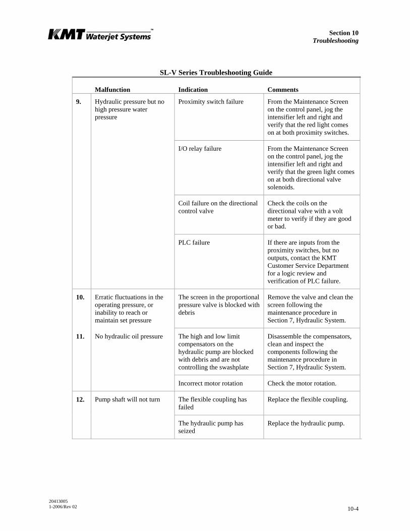
Section 10 Troubleshooting
20413005 1-2006/Rev 02 10-4
SL-V Series Troubleshooting Guide
Malfunction Indication Comments
Proximity switch failure From the Maintenance Screen on the control panel, jog the intensifier left and right and verify that the red light comes on at both proximity switches.
I/O relay failure From the Maintenance Screen on the control panel, jog the intensifier left and right and verify that the green light comes on at both directional valve solenoids.
Coil failure on the directional control valve
Check the coils on the directional valve with a volt meter to verify if they are good or bad.
9. Hydraulic pressure but no high pressure water pressure
PLC failure If there are inputs from the proximity switches, but no outputs, contact the KMT Customer Service Department for a logic review and verification of PLC failure.
10. Erratic fluctuations in the operating pressure, or inability to reach or maintain set pressure
The screen in the proportional pressure valve is blocked with debris
Remove the valve and clean the screen following the maintenance procedure in Section 7, Hydraulic System.
The high and low limit compensators on the hydraulic pump are blocked with debris and are not controlling the swashplate
Disassemble the compensators, clean and inspect the components following the maintenance procedure in Section 7, Hydraulic System.
11. No hydraulic oil pressure
Incorrect motor rotation Check the motor rotation.
12. Pump shaft will not turn The flexible coupling has failed
Replace the flexible coupling.
The hydraulic pump has seized
Replace the hydraulic pump.
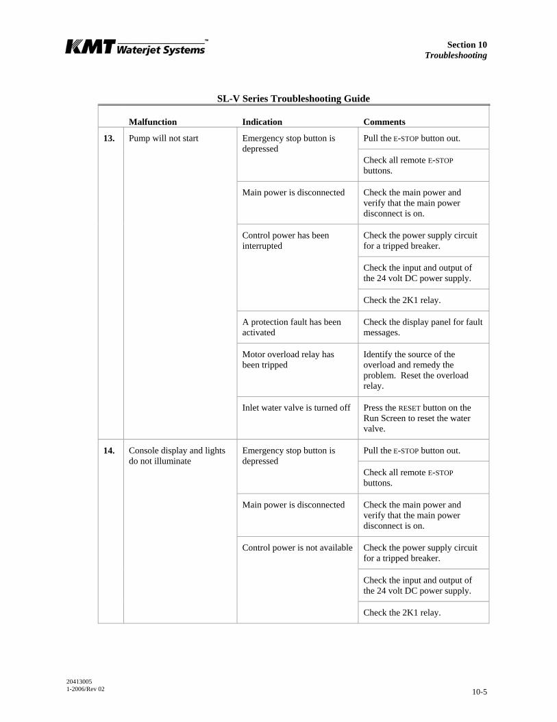
Section 10 Troubleshooting
20413005 1-2006/Rev 02 10-5
SL-V Series Troubleshooting Guide
Malfunction Indication Comments
Pull the E-STOP button out. Emergency stop button is depressed
Check all remote E-STOP buttons.
Main power is disconnected Check the main power and verify that the main power disconnect is on.
Check the power supply circuit for a tripped breaker.
Check the input and output of the 24 volt DC power supply.
Control power has been interrupted
Check the 2K1 relay.
A protection fault has been activated
Check the display panel for fault messages.
Motor overload relay has been tripped
Identify the source of the overload and remedy the problem. Reset the overload relay.
13. Pump will not start
Inlet water valve is turned off Press the RESET button on the Run Screen to reset the water valve.
Pull the E-STOP button out. Emergency stop button is depressed
Check all remote E-STOP buttons.
Main power is disconnected Check the main power and verify that the main power disconnect is on.
Check the power supply circuit for a tripped breaker.
Check the input and output of the 24 volt DC power supply.
14. Console display and lights do not illuminate
Control power is not available
Check the 2K1 relay.

Section 10 Troubleshooting
20413005 1-2006/Rev 02 10-6
SL-V Series Troubleshooting Guide
Malfunction Indication Comments
Unsafe operation has been detected
Check the display panel for fault messages.
Check the power supply circuit for a tripped breaker.
Check the input and output of the 24 volt DC power supply.
Verify that power is available at the main power source.
Check the 2K1 relay coil.
Electrical power has been interrupted
Check the 4K0 relay.
15. Pump quits running
Motor overload relay has been tripped
Identify the source of the overload and remedy the problem. Reset the overload relay.
Circuit breaker has been tripped
Check the input and output of all circuit breakers.
Power supply fault Check the input and output voltages at the power supply.
Pull the E-STOP button out. Emergency stop button is depressed
Check all remote E-STOP buttons.
Master control relay is not energized
Verify that the contactor coil is pulling in on the master control relay.
16. No control power
Contact set failure on the master control relay
Verify that the contact sets on the master control relay are changing states when the relay is energized.
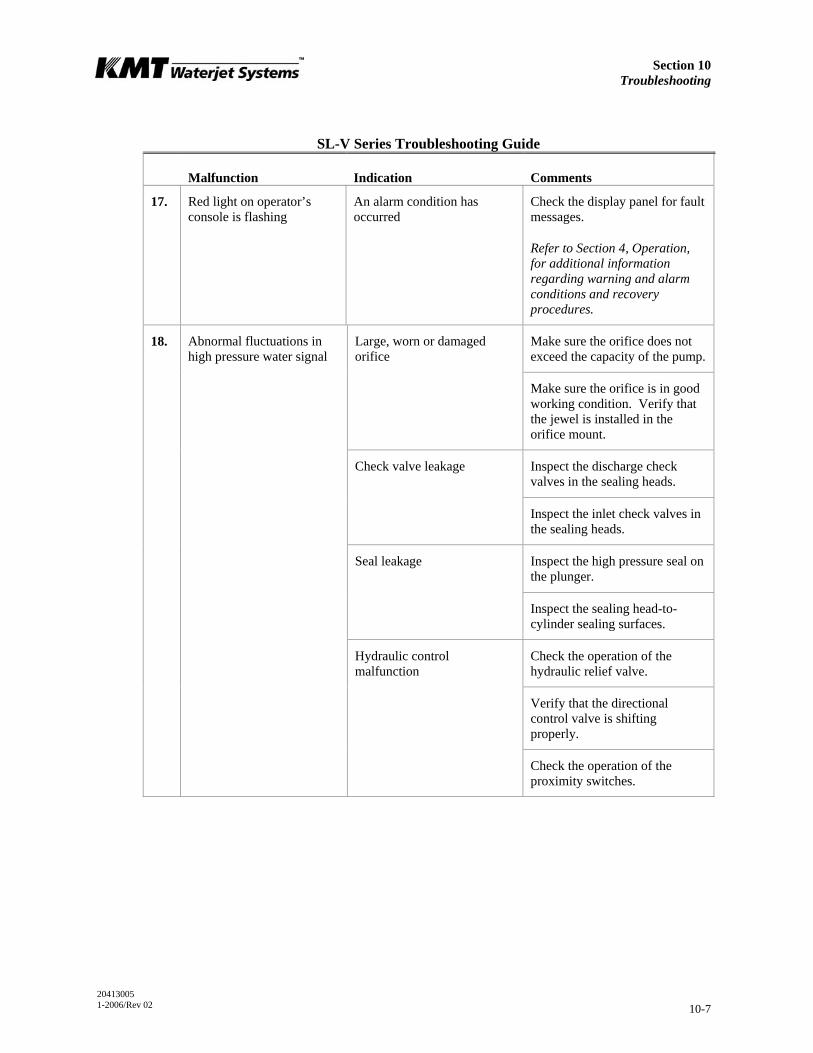
Section 10 Troubleshooting
20413005 1-2006/Rev 02 10-7
SL-V Series Troubleshooting Guide
Malfunction Indication Comments
17. Red light on operator’s console is flashing
An alarm condition has occurred
Check the display panel for fault messages.
Refer to Section 4, Operation, for additional information regarding warning and alarm conditions and recovery procedures.
Make sure the orifice does not exceed the capacity of the pump.
Large, worn or damaged orifice
Make sure the orifice is in good working condition. Verify that the jewel is installed in the orifice mount.
Inspect the discharge check valves in the sealing heads.
Check valve leakage
Inspect the inlet check valves in the sealing heads.
Inspect the high pressure seal on the plunger.
Seal leakage
Inspect the sealing head-to-cylinder sealing surfaces.
Check the operation of the hydraulic relief valve.
Verify that the directional control valve is shifting properly.
18. Abnormal fluctuations in high pressure water signal
Hydraulic control malfunction
Check the operation of the proximity switches.
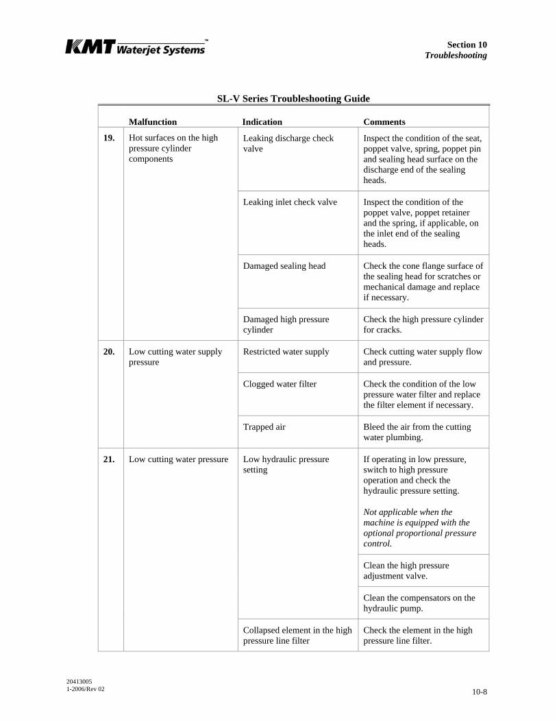
Section 10 Troubleshooting
20413005 1-2006/Rev 02 10-8
SL-V Series Troubleshooting Guide
Malfunction Indication Comments
Leaking discharge check valve
Inspect the condition of the seat, poppet valve, spring, poppet pin and sealing head surface on the discharge end of the sealing heads.
Leaking inlet check valve Inspect the condition of the poppet valve, poppet retainer and the spring, if applicable, on the inlet end of the sealing heads.
Damaged sealing head Check the cone flange surface of the sealing head for scratches or mechanical damage and replace if necessary.
19. Hot surfaces on the high pressure cylinder components
Damaged high pressure cylinder
Check the high pressure cylinder for cracks.
Restricted water supply Check cutting water supply flow and pressure.
Clogged water filter Check the condition of the low pressure water filter and replace the filter element if necessary.
20. Low cutting water supply pressure
Trapped air Bleed the air from the cutting water plumbing.
If operating in low pressure, switch to high pressure operation and check the hydraulic pressure setting.
Not applicable when the machine is equipped with the optional proportional pressure control.
Clean the high pressure adjustment valve.
Low hydraulic pressure setting
Clean the compensators on the hydraulic pump.
21. Low cutting water pressure
Collapsed element in the high pressure line filter
Check the element in the high pressure line filter.
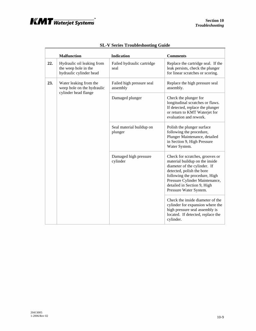
Section 10 Troubleshooting
20413005 1-2006/Rev 02 10-9
SL-V Series Troubleshooting Guide
Malfunction Indication Comments
22. Hydraulic oil leaking from the weep hole in the hydraulic cylinder head
Failed hydraulic cartridge seal
Replace the cartridge seal. If the leak persists, check the plunger for linear scratches or scoring.
Failed high pressure seal assembly
Replace the high pressure seal assembly.
Damaged plunger Check the plunger for longitudinal scratches or flaws. If detected, replace the plunger or return to KMT Waterjet for evaluation and rework.
Seal material buildup on plunger
Polish the plunger surface following the procedure, Plunger Maintenance, detailed in Section 9, High Pressure Water System.
Check for scratches, grooves or material buildup on the inside diameter of the cylinder. If detected, polish the bore following the procedure, High Pressure Cylinder Maintenance, detailed in Section 9, High Pressure Water System.
23. Water leaking from the weep hole on the hydraulic cylinder head flange
Damaged high pressure cylinder
Check the inside diameter of the cylinder for expansion where the high pressure seal assembly is located. If detected, replace the cylinder.
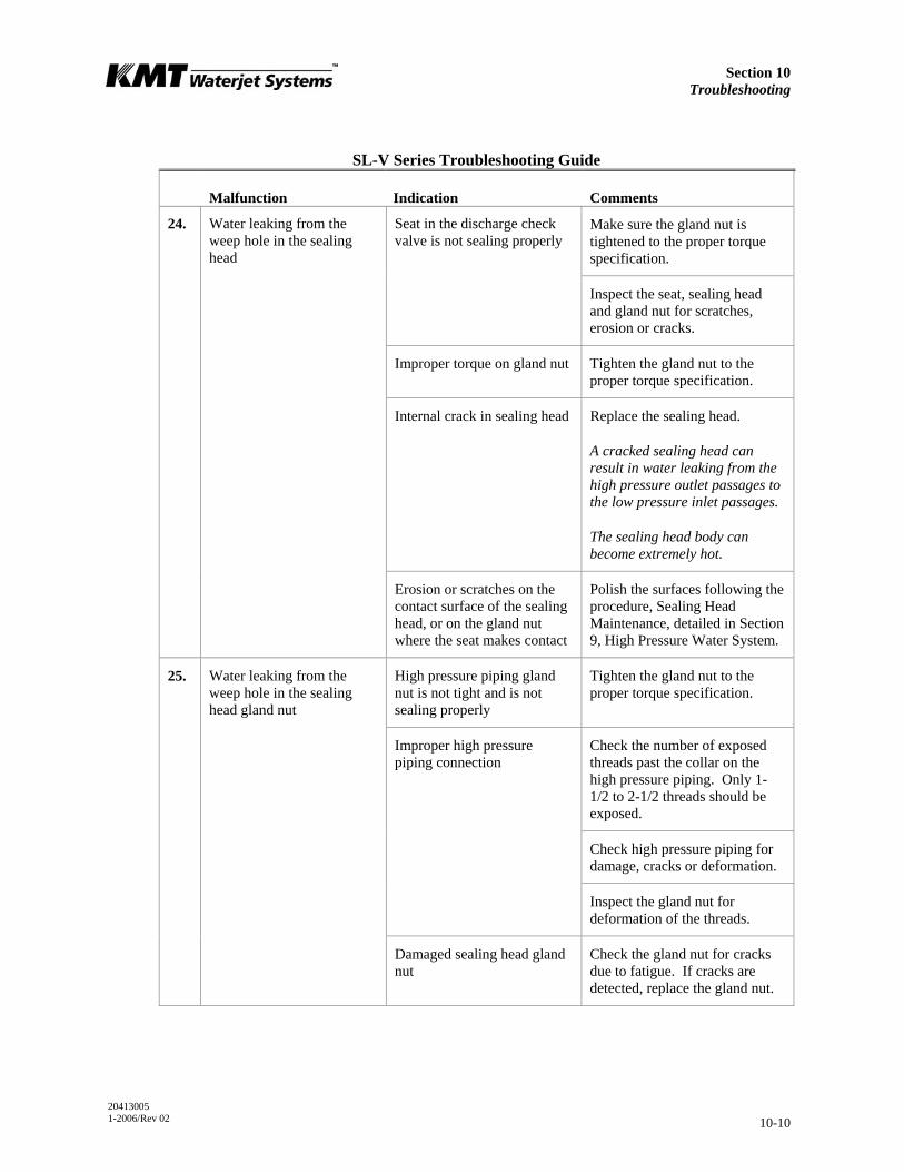
Section 10 Troubleshooting
20413005 1-2006/Rev 02 10-10
SL-V Series Troubleshooting Guide
Malfunction Indication Comments
Make sure the gland nut is tightened to the proper torque specification.
Seat in the discharge check valve is not sealing properly
Inspect the seat, sealing head and gland nut for scratches, erosion or cracks.
Improper torque on gland nut Tighten the gland nut to the proper torque specification.
Internal crack in sealing head Replace the sealing head.
A cracked sealing head can result in water leaking from the high pressure outlet passages to the low pressure inlet passages.
The sealing head body can become extremely hot.
24. Water leaking from the weep hole in the sealing head
Erosion or scratches on the contact surface of the sealing head, or on the gland nut where the seat makes contact
Polish the surfaces following the procedure, Sealing Head Maintenance, detailed in Section 9, High Pressure Water System.
High pressure piping gland nut is not tight and is not sealing properly
Tighten the gland nut to the proper torque specification.
Check the number of exposed threads past the collar on the high pressure piping. Only 1-1/2 to 2-1/2 threads should be exposed.
Check high pressure piping for damage, cracks or deformation.
Improper high pressure piping connection
Inspect the gland nut for deformation of the threads.
25. Water leaking from the weep hole in the sealing head gland nut
Damaged sealing head gland nut
Check the gland nut for cracks due to fatigue. If cracks are detected, replace the gland nut.

Section 10 Troubleshooting
20413005 1-2006/Rev 02 10-11
SL-V Series Troubleshooting Guide
Malfunction Indication Comments
Check for scratches or grooves on the 45-degree cone seal surface. If detected, polish to remove following the procedure, High Pressure Cylinder Maintenance, detailed in Section 9, High Pressure Water System.
Damaged high pressure cylinder
Replace the high pressure cylinder.
External crack in sealing head Replace the sealing head.
Damaged sealing head Check for scratches or grooves on the 45-degree surface of the sealing head. If detected, polish the surface following the procedure, Sealing Head Maintenance, detailed in Section 9, High Pressure Water System.
26. Water leaking from the weep holes in the hard seal end cap
Improper torque on jackbolts Re-torque the jackbolts to the proper torque specification.
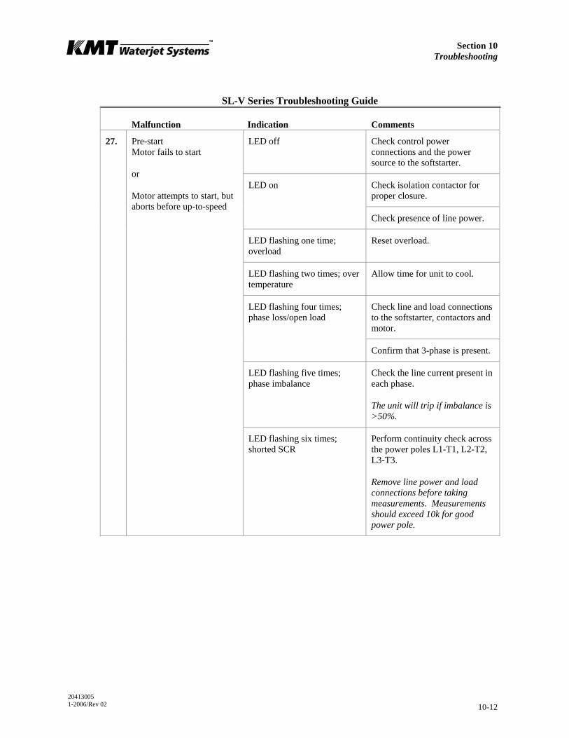
Section 10 Troubleshooting
20413005 1-2006/Rev 02 10-12
SL-V Series Troubleshooting Guide
Malfunction Indication Comments
LED off Check control power connections and the power source to the softstarter.
Check isolation contactor for proper closure.
LED on
Check presence of line power.
LED flashing one time; overload
Reset overload.
LED flashing two times; over temperature
Allow time for unit to cool.
Check line and load connections to the softstarter, contactors and motor.
LED flashing four times; phase loss/open load
Confirm that 3-phase is present.
LED flashing five times; phase imbalance
Check the line current present in each phase.
The unit will trip if imbalance is >50%.
27. Pre-start Motor fails to start
or
Motor attempts to start, but aborts before up-to-speed
LED flashing six times; shorted SCR
Perform continuity check across the power poles L1-T1, L2-T2, L3-T3.
Remove line power and load connections before taking measurements. Measurements should exceed 10k for good power pole.
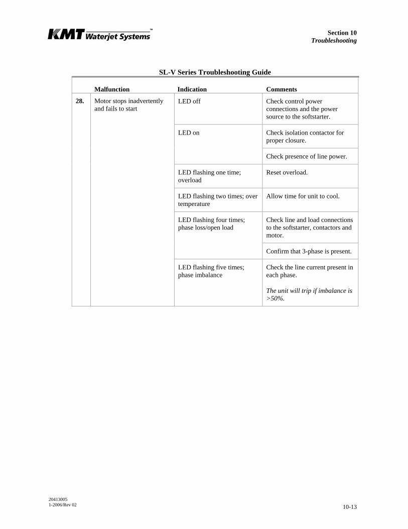
Section 10 Troubleshooting
20413005 1-2006/Rev 02 10-13
SL-V Series Troubleshooting Guide
Malfunction Indication Comments
LED off Check control power connections and the power source to the softstarter.
Check isolation contactor for proper closure.
LED on
Check presence of line power.
LED flashing one time; overload
Reset overload.
LED flashing two times; over temperature
Allow time for unit to cool.
Check line and load connections to the softstarter, contactors and motor.
LED flashing four times; phase loss/open load
Confirm that 3-phase is present.
28. Motor stops inadvertently and fails to start
LED flashing five times; phase imbalance
Check the line current present in each phase.
The unit will trip if imbalance is >50%.

20413013 1-2006/Rev 02 11-1
SECTION 11 SPECIFICATIONS
11.1 Overview
A comprehensive listing of specifications for the SL-V Plus models listed in Table 11-1 are provided in this section.
Table 11-1 SL-V Plus Models
Motor Horsepower Rating
Model HP Kw
SL-V 30 30 22
SL-V 50 50 37
SL-V 60 60 45
SL-V 75 75 56
SL-V 100 100 75
SL-V 100D 100 75
11.2 Installation Specifications
Environment
Installation location Indoors
Air borne dust/contaminants Minimal
Ambient temperature
Minimum storage 36° F (2° C)
Minimum operating 40° F (5° C)
Maximum operating 104° F (40° C)
Maximum relative humidity* (at maximum operating temperature)
95%
*Note: When the relative humidity is above 50%, the oil in the reservoir should be checked frequently for water content.
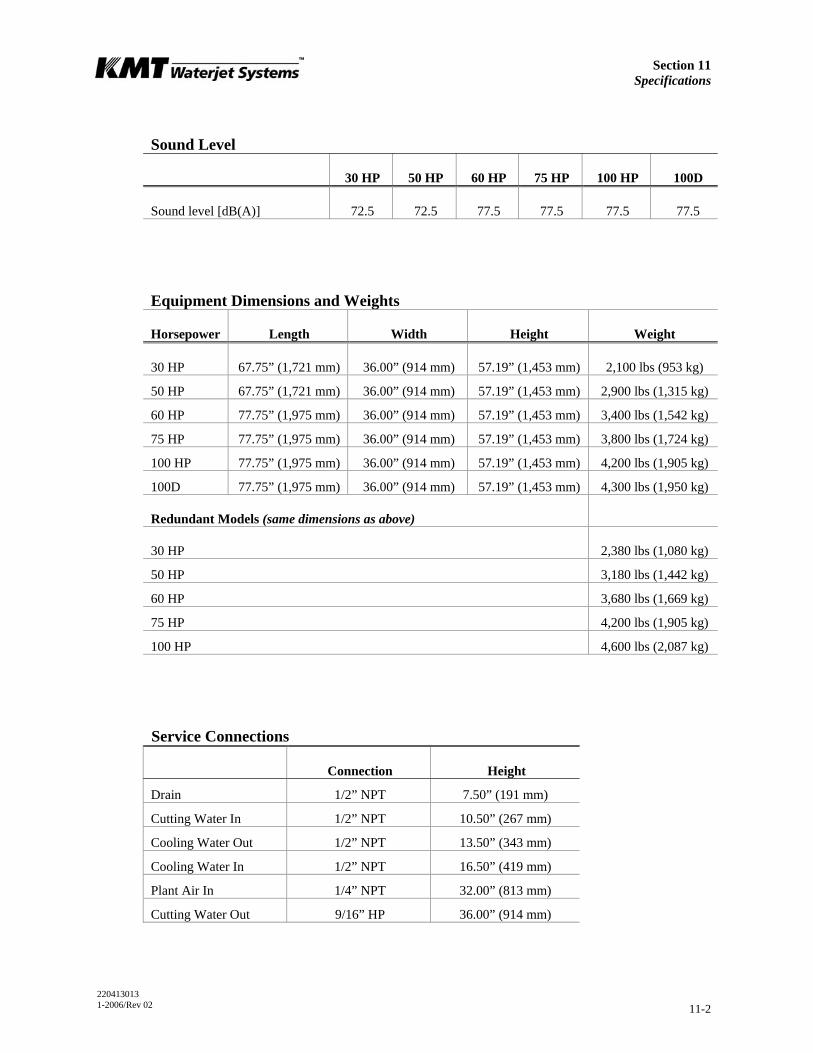
Section 11 Specifications
220413013 1-2006/Rev 02 11-2
Sound Level
30 HP 50 HP 60 HP 75 HP 100 HP 100D
Sound level [dB(A)] 72.5 72.5 77.5 77.5 77.5 77.5
Equipment Dimensions and Weights
Horsepower Length Width Height Weight
30 HP 67.75” (1,721 mm) 36.00” (914 mm) 57.19” (1,453 mm) 2,100 lbs (953 kg)
50 HP 67.75” (1,721 mm) 36.00” (914 mm) 57.19” (1,453 mm) 2,900 lbs (1,315 kg)
60 HP 77.75” (1,975 mm) 36.00” (914 mm) 57.19” (1,453 mm) 3,400 lbs (1,542 kg)
75 HP 77.75” (1,975 mm) 36.00” (914 mm) 57.19” (1,453 mm) 3,800 lbs (1,724 kg)
100 HP 77.75” (1,975 mm) 36.00” (914 mm) 57.19” (1,453 mm) 4,200 lbs (1,905 kg)
100D 77.75” (1,975 mm) 36.00” (914 mm) 57.19” (1,453 mm) 4,300 lbs (1,950 kg)
Redundant Models (same dimensions as above)
30 HP 2,380 lbs (1,080 kg)
50 HP 3,180 lbs (1,442 kg)
60 HP 3,680 lbs (1,669 kg)
75 HP 4,200 lbs (1,905 kg)
100 HP 4,600 lbs (2,087 kg)
Service Connections
Connection Height
Drain 1/2” NPT 7.50” (191 mm)
Cutting Water In 1/2” NPT 10.50” (267 mm)
Cooling Water Out 1/2” NPT 13.50” (343 mm)
Cooling Water In 1/2” NPT 16.50” (419 mm)
Plant Air In 1/4” NPT 32.00” (813 mm)
Cutting Water Out 9/16” HP 36.00” (914 mm)
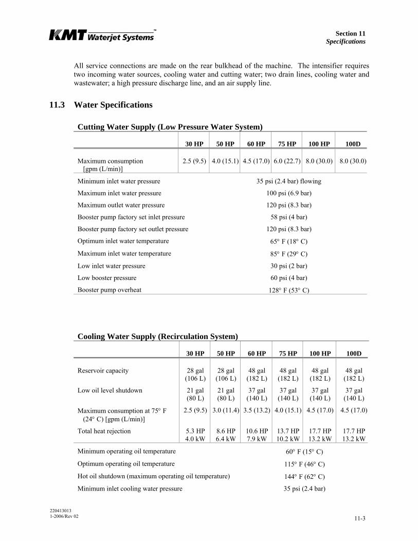
Section 11 Specifications
220413013 1-2006/Rev 02 11-3
All service connections are made on the rear bulkhead of the machine. The intensifier requires two incoming water sources, cooling water and cutting water; two drain lines, cooling water and wastewater; a high pressure discharge line, and an air supply line.
11.3 Water Specifications
Cutting Water Supply (Low Pressure Water System)
30 HP 50 HP 60 HP 75 HP 100 HP 100D
Maximum consumption [gpm (L/min)]
2.5 (9.5) 4.0 (15.1) 4.5 (17.0) 6.0 (22.7) 8.0 (30.0) 8.0 (30.0)
Minimum inlet water pressure 35 psi (2.4 bar) flowing
Maximum inlet water pressure 100 psi (6.9 bar)
Maximum outlet water pressure 120 psi (8.3 bar)
Booster pump factory set inlet pressure 58 psi (4 bar)
Booster pump factory set outlet pressure 120 psi (8.3 bar)
Optimum inlet water temperature 65° F (18° C)
Maximum inlet water temperature 85° F (29° C)
Low inlet water pressure 30 psi (2 bar)
Low booster pressure 60 psi (4 bar)
Booster pump overheat 128° F (53° C)
Cooling Water Supply (Recirculation System)
30 HP 50 HP 60 HP 75 HP 100 HP 100D
Reservoir capacity 28 gal (106 L)
28 gal(106 L)
48 gal (182 L)
48 gal (182 L)
48 gal (182 L)
48 gal(182 L)
Low oil level shutdown 21 gal (80 L)
21 gal(80 L)
37 gal (140 L)
37 gal (140 L)
37 gal (140 L)
37 gal(140 L)
Maximum consumption at 75° F (24° C) [gpm (L/min)]
2.5 (9.5) 3.0 (11.4) 3.5 (13.2) 4.0 (15.1) 4.5 (17.0) 4.5 (17.0)
Total heat rejection 5.3 HP4.0 kW
8.6 HP6.4 kW
10.6 HP7.9 kW
13.7 HP 10.2 kW
17.7 HP 13.2 kW
17.7 HP13.2 kW
Minimum operating oil temperature 60° F (15° C)
Optimum operating oil temperature 115° F (46° C)
Hot oil shutdown (maximum operating oil temperature) 144° F (62° C)
Minimum inlet cooling water pressure 35 psi (2.4 bar)

Section 11 Specifications
220413013 1-2006/Rev 02 11-4
Cooling Water Supply (Recirculation System) Maximum inlet cooling water pressure 100 psi (6.9 bar)
Oil filtration rating (Beta filtration rating) β10≥100*
Fluid cleanliness rating (ISO fluid cleanliness rating)) 17/14**
Nominal recirculation pressure 30 psi (2 bar)
Recommended oil type
General service Mobil #DTE Heavy Medium, No. 021029
Conoco Hydroclear TM multi-purpose R&O
Food service Anderol PQ AA 20 Food Grade
* Note: For each particle per milliliter downstream of the filer greater than 10 microns, there are 100 particles per milliliter larger than 10 microns upstream of the filter.
**Note: Indicates ISO 4406 range numbers for maximum permissible number of particles per milliliter, greater than 5 and 15 microns.
17 <1,300 particles per milliliter, >5 microns
14 <160 particles per milliliter, >15 microns
Water Quality Standards
The quality of the inlet cutting water supply is one of the most important factors affecting component life and performance. Water treatment requirements can be determined by a water analysis.
The cutting water supply must meet the following standards. A high concentration of dissolved solids, especially calcium, silica and chlorides will affect high pressure component life.
Table 11-2 Water Quality Standards
Constituent (mg/l)
Minimum Requirement
Better
Best
Alkalinity 50 25 10
Calcium 25 5 0.5
Carbon Dioxide 0 0 0
Chloride 100 15 1
Free Chlorine 1 1 0.05
Iron 0.2 0.1 0.01
Magnesium as Mg 0.5 0.1 0.1
Manganese as Mn 0.1 0.1 0.1
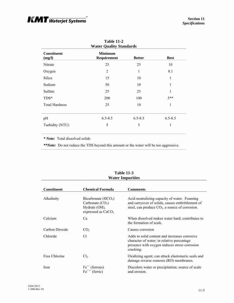
Section 11 Specifications
220413013 1-2006/Rev 02 11-5
Table 11-2 Water Quality Standards
Constituent (mg/l)
Minimum Requirement
Better
Best
Nitrate 25 25 10
Oxygen 2 1 0.1
Silica 15 10 1
Sodium 50 10 1
Sulfate 25 25 1
TDS* 200 100 5**
Total Hardness 25 10 1
pH 6.5-8.5 6.5-8.5 6.5-8.5
Turbidity (NTU) 5 5 1
* Note: Total dissolved solids
**Note: Do not reduce the TDS beyond this amount or the water will be too aggressive.
Table 11-3 Water Impurities
Constituent
Chemical Formula
Comments
Alkalinity Bicarbonate (HCO3) Carbonate (CO3) Hydrate (OH), expressed as CaCO3
Acid neutralizing capacity of water. Foaming and carryover of solids, causes embrittlement of steel, can produce CO2, a source of corrosion.
Calcium Ca When dissolved makes water hard; contributes to the formation of scale.
Carbon Dioxide CO2 Causes corrosion
Chloride Cl Adds to solid content and increases corrosive character of water; in relative percentage presence with oxygen induces stress corrosion cracking.
Free Chlorine Cl2 Oxidizing agent; can attack elastomeric seals and damage reverse osmosis (RO) membranes.
Iron Fe++ (ferrous) Fe+++ (ferric)
Discolors water or precipitation; source of scale and erosion.
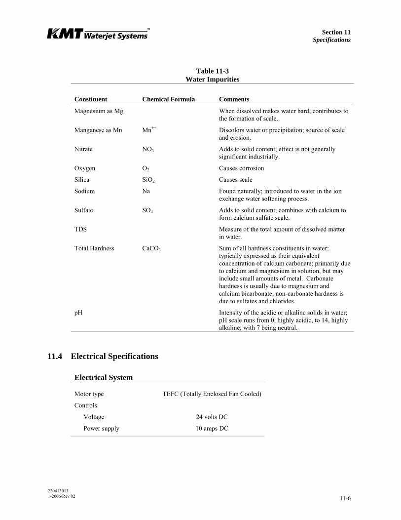
Section 11 Specifications
220413013 1-2006/Rev 02 11-6
Table 11-3 Water Impurities
Constituent
Chemical Formula
Comments
Magnesium as Mg When dissolved makes water hard; contributes to the formation of scale.
Manganese as Mn Mn++ Discolors water or precipitation; source of scale and erosion.
Nitrate NO3 Adds to solid content; effect is not generally significant industrially.
Oxygen O2 Causes corrosion
Silica SiO2 Causes scale
Sodium Na Found naturally; introduced to water in the ion exchange water softening process.
Sulfate SO4 Adds to solid content; combines with calcium to form calcium sulfate scale.
TDS Measure of the total amount of dissolved matter in water.
Total Hardness CaCO3 Sum of all hardness constituents in water; typically expressed as their equivalent concentration of calcium carbonate; primarily due to calcium and magnesium in solution, but may include small amounts of metal. Carbonate hardness is usually due to magnesium and calcium bicarbonate; non-carbonate hardness is due to sulfates and chlorides.
pH Intensity of the acidic or alkaline solids in water; pH scale runs from 0, highly acidic, to 14, highly alkaline; with 7 being neutral.
11.4 Electrical Specifications
Electrical System
Motor type TEFC (Totally Enclosed Fan Cooled)
Controls
Voltage 24 volts DC
Power supply 10 amps DC
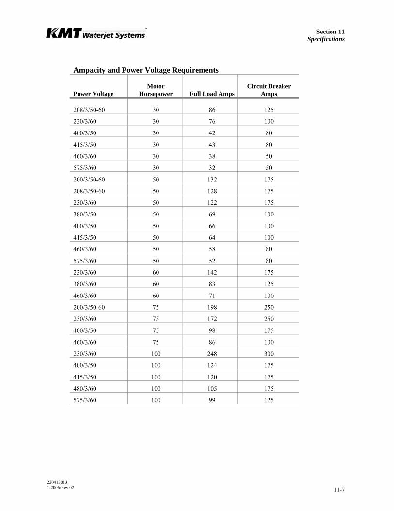
Section 11 Specifications
220413013 1-2006/Rev 02 11-7
Ampacity and Power Voltage Requirements
Power Voltage
Motor Horsepower
Full Load Amps
Circuit Breaker Amps
208/3/50-60 30 86 125
230/3/60 30 76 100
400/3/50 30 42 80
415/3/50 30 43 80
460/3/60 30 38 50
575/3/60 30 32 50
200/3/50-60 50 132 175
208/3/50-60 50 128 175
230/3/60 50 122 175
380/3/50 50 69 100
400/3/50 50 66 100
415/3/50 50 64 100
460/3/60 50 58 80
575/3/60 50 52 80
230/3/60 60 142 175
380/3/60 60 83 125
460/3/60 60 71 100
200/3/50-60 75 198 250
230/3/60 75 172 250
400/3/50 75 98 175
460/3/60 75 86 100
230/3/60 100 248 300
400/3/50 100 124 175
415/3/50 100 120 175
480/3/60 100 105 175
575/3/60 100 99 125

Section 11 Specifications
220413013 1-2006/Rev 02 11-8
11.5 Hydraulic and High Pressure Water System Specifications
Hydraulic System
30 HP 50 HP 60 HP 75 HP 100 HP 100D
Maximum operating pressure 3,000 psi (207 bar) 2,600 psi (179 bar)
Main system relief valve 3,400 psi (234 bar)
High Pressure Water System
30 HP 50 HP 60 HP 75 HP 100 HP 100D
Plunger diameter [inches (mm)] 0.875 (22)
0.875 (22)
0.875 (22)
1.125 (29)
1.125 (29)
0.875 (22)
Piston diameter [inches (mm)] 4.03 (102.4)
4.03 (102.4)
4.03 (102.4)
5.50 (139.7)
5.50 (139.7)
4.03 (102.4)
Intensification ratio 20:1 20:1 20:1 23:1 23:1 20:1
Maximum flow rate
55,000 psi (3,792 bar) [gpm (L/min)]
0.60 (2.27)
1.00 (3.79)
1.12 (4.24)
1.44 (5.45)
2.00 (7.57)
2.00 (7.57)
60,000 psi (4,137 bar) [gpm (L/min)]
0.52 (1.97)
0.90 (3.41)
1.02 (3.86)
1.34 (5.07)
1.88 (7.12)
1.88 (7.12)
Minimum outlet pressure 5,000 psi (345 bar)
Maximum outlet pressure 60,000 psi (4,137 bar)
Pneumatic Control Valve
Maximum water pressure 60,000 psi (4,137 bar)
Minimum air pressure 85 psi (5.9 bar)
Maximum air pressure 100 psi (6.9 bar)
Maximum flow rate 1.0 cfm (0.028) m3/min
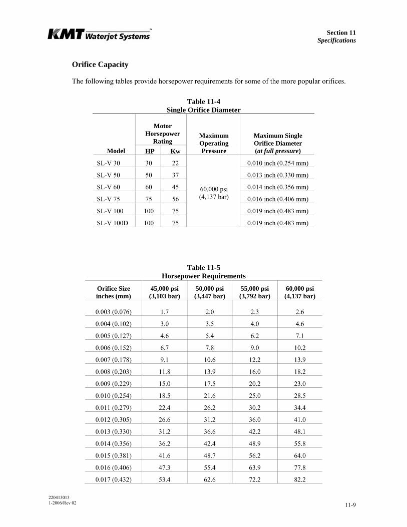
Section 11 Specifications
220413013 1-2006/Rev 02 11-9
Orifice Capacity
The following tables provide horsepower requirements for some of the more popular orifices.
Table 11-4 Single Orifice Diameter
Motor Horsepower
Rating
Model HP Kw
Maximum Operating Pressure
Maximum Single Orifice Diameter (at full pressure)
SL-V 30 30 22 0.010 inch (0.254 mm)
SL-V 50 50 37 0.013 inch (0.330 mm)
SL-V 60 60 45 0.014 inch (0.356 mm)
SL-V 75 75 56 0.016 inch (0.406 mm)
SL-V 100 100 75 0.019 inch (0.483 mm)
SL-V 100D 100 75
60,000 psi (4,137 bar)
0.019 inch (0.483 mm)
Table 11-5 Horsepower Requirements
Orifice Size inches (mm)
45,000 psi (3,103 bar)
50,000 psi (3,447 bar)
55,000 psi (3,792 bar)
60,000 psi (4,137 bar)
0.003 (0.076) 1.7 2.0 2.3 2.6
0.004 (0.102) 3.0 3.5 4.0 4.6
0.005 (0.127) 4.6 5.4 6.2 7.1
0.006 (0.152) 6.7 7.8 9.0 10.2
0.007 (0.178) 9.1 10.6 12.2 13.9
0.008 (0.203) 11.8 13.9 16.0 18.2
0.009 (0.229) 15.0 17.5 20.2 23.0
0.010 (0.254) 18.5 21.6 25.0 28.5
0.011 (0.279) 22.4 26.2 30.2 34.4
0.012 (0.305) 26.6 31.2 36.0 41.0
0.013 (0.330) 31.2 36.6 42.2 48.1
0.014 (0.356) 36.2 42.4 48.9 55.8
0.015 (0.381) 41.6 48.7 56.2 64.0
0.016 (0.406) 47.3 55.4 63.9 77.8
0.017 (0.432) 53.4 62.6 72.2 82.2

Section 11 Specifications
220413013 1-2006/Rev 02 11-10
Table 11-5 Horsepower Requirements
Orifice Size inches (mm)
45,000 psi (3,103 bar)
50,000 psi (3,447 bar)
55,000 psi (3,792 bar)
60,000 psi (4,137 bar)
0.018 (0.457) 59.9 70.1 80.9 92.2
0.019 (0.483) 66.7 78.1 90.1 102.7
0.020 (0.508) 73.9 86.6 99.9 113.8
0.021 (0.533) 81.5 95.4 110.1 125.5
0.022 (0.559) 89.4 104.8 120.9 137.7
0.023 (0.584) 97.8 114.5 132.1 150.5
The horsepower requirements for operating multiple orifices are determined by adding the requirements in Table 11-5 for each orifice. Examples are shown below.
Orifice Size inches (mm)
Number of Orifices
Operating Pressure
Calculation
Total Horsepower
0.009 (0.229) 3 55,000 3 x 20.2 60.6
0.015 (0.381) 0.010 (0.254)
1 1 50,000 48.7 + 21.6 70.3
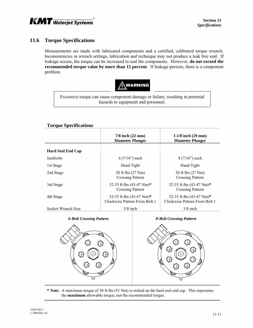
Section 11 Specifications
220413013 1-2006/Rev 02 11-11
11.6 Torque Specifications
Measurements are made with lubricated components and a certified, calibrated torque wrench. Inconsistencies in wrench settings, lubrication and technique may not produce a leak free seal. If leakage occurs, the torque can be increased to seal the components. However, do not exceed the recommended torque value by more than 15 percent. If leakage persists, there is a component problem.
Excessive torque can cause component damage or failure, resulting in potential hazards to equipment and personnel.
Torque Specifications
7/8 inch (22 mm) Diameter Plunger
1-1/8 inch (29 mm) Diameter Plunger
Hard Seal End Cap
Jackbolts 6 (7/16”) each 8 (7/16”) each
1st Stage Hand Tight Hand Tight
2nd Stage 20 ft-lbs (27 Nm) Crossing Pattern
20 ft-lbs (27 Nm) Crossing Pattern
3rd Stage 32-35 ft-lbs (43-47 Nm)* Crossing Pattern
32-35 ft-lbs (43-47 Nm)* Crossing Pattern
4th Stage 32-35 ft-lbs (43-47 Nm)* Clockwise Pattern From Bolt 1
32-35 ft-lbs (43-47 Nm)* Clockwise Pattern From Bolt 1
Socket Wrench Size 3/8 inch 3/8 inch
6-Bolt Crossing Pattern 8-Bolt Crossing Pattern
* Note: A maximum torque of 38 ft-lbs (51 Nm) is etched on the hard seal end cap. This represents the maximum allowable torque, not the recommended torque.

Section 11 Specifications
220413013 1-2006/Rev 02 11-12
Torque Specifications
7/8 inch (22 mm) Diameter Plunger
1-1/8 inch (29 mm) Diameter Plunger
Hydraulic Cylinder Head
Socket Head Screws 8 (14M) each 6 (3/4”) each
Torque 75-80 ft-lbs (102-108 Nm) 170-175 ft-lbs (230-237 Nm)
Hex Key M12 5/8 inch
Proximity Switch
Socket Head Screws 2 (M6) each 2 (1/4”) each
Torque 140-160 in-lbs (16-18 Nm) 140-160 in-lbs (16-18 Nm)
Hex Key M5 3/16 inch
Stem Mount
Socket Head Screws 4 (M10) each 4 (3/8”) each
Torque 60-65 ft-lbs (80-88 Nm) 35-40 ft-lbs (47-54 Nm)
Hex Key M8 5/16 inch
Sealing Head
Discharge Gland Nut 130 ft-lbs (176 Nm) 200 ft-lbs (271 Nm)
Poppet Retainer 25-30 in-lbs (2.8-3.4 Nm) 25-30 in-lbs (2.8-3.4 Nm)
Pneumatic Control Valve
3/8-inch HP Inlet Gland Nut 50 ft-lbs (68 Nm)
1/4-inch Outlet to Drain 25 ft-lbs (34 Nm)
Pneumatic Actuator 5 ft-lbs (7 Nm)
9/16”-1/4” HP Adapter 50 ft-lbs (68 Nm)
High Pressure Fittings
1/4-inch Gland Nut 25 ft-lb (34 Nm)
3/8-inch Gland Nut 50 ft-lb (68 Nm)
9/16-inch Gland Nut 110 ft-lb (149 Nm)
20413054 1-2006/Rev 04 12-1
SECTION 12 PARTS LIST
12.1 Overview
This section contains a comprehensive list of all standard and optional parts for the 50 horsepower SL-V Plus, maintenance tools, installation and equipment accessories. To facilitate the ordering of replacement parts, item numbers in each table correspond to the identifying numbers in the accompanying figures.
Use the following information to contact the Spare Parts Department at KMT Waterjet Systems.
USA Europe
Parts Department KMT Waterjet Systems Production Equipment Group 635 West 12th Street Baxter Springs, KS 66713-0231
Spare Parts Manager KMT Waterjet Systems GmbH Wasserstrahl Schneidetechnik Auf der Laukert 11 D-61231 Bad Nauheim Germany
Phone Fax Email
(800) 826-9274 (620) 856-5050 [email protected]
PhoneFax Email
+49-6032-997-119 +49-6032-997-271 [email protected]
Section 12 Parts List
20413054 1-2006/Rev 04 12-2
12.2 Part Nomenclature
The following list explains the abbreviations and numerical sizes used in the following part descriptions.
Abbreviations and Nominal Size Guide
Item
Description
1/4, 9/16, 3/4 Nominal sizes in fractions of an inch
D Degree
HP or LP High pressure or low pressure
ID or OD Inside diameter or outside diameter
JIC 37-degree flared, threaded hydraulic fitting
NO or NC Normally open or normally closed
NPT National Pipe Thread, pipe thread and pressure vessel standard
psi or ksi Pounds per square inch or thousands of pounds per square inch
SAE O-Ring O-ring threaded port style, Society of Automotive Engineers (SAE) standard
TUV German pressure vessel code and inspection agency
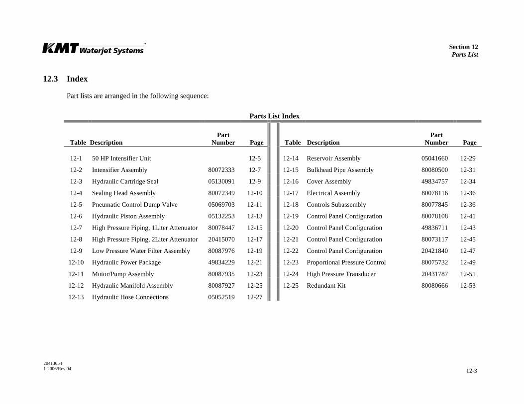
Section 12 Parts List
20413054 1-2006/Rev 04 12-3
12.3 Index
Part lists are arranged in the following sequence:
Parts List Index
Table
Description
Part Number
Page
Table
Description
Part Number
Page
12-1 50 HP Intensifier Unit 12-5 12-14 Reservoir Assembly 05041660 12-29
12-2 Intensifier Assembly 80072333 12-7 12-15 Bulkhead Pipe Assembly 80080500 12-31
12-3 Hydraulic Cartridge Seal 05130091 12-9 12-16 Cover Assembly 49834757 12-34
12-4 Sealing Head Assembly 80072349 12-10 12-17 Electrical Assembly 80078116 12-36
12-5 Pneumatic Control Dump Valve 05069703 12-11 12-18 Controls Subassembly 80077845 12-36
12-6 Hydraulic Piston Assembly 05132253 12-13 12-19 Control Panel Configuration 80078108 12-41
12-7 High Pressure Piping, 1Liter Attenuator 80078447 12-15 12-20 Control Panel Configuration 49836711 12-43
12-8 High Pressure Piping, 2Liter Attenuator 20415070 12-17 12-21 Control Panel Configuration 80073117 12-45
12-9 Low Pressure Water Filter Assembly 80087976 12-19 12-22 Control Panel Configuration 20421840 12-47
12-10 Hydraulic Power Package 49834229 12-21 12-23 Proportional Pressure Control 80075732 12-49
12-11 Motor/Pump Assembly 80087935 12-23 12-24 High Pressure Transducer 20431787 12-51
12-12 Hydraulic Manifold Assembly 80087927 12-25 12-25 Redundant Kit 80080666 12-53
12-13 Hydraulic Hose Connections 05052519 12-27
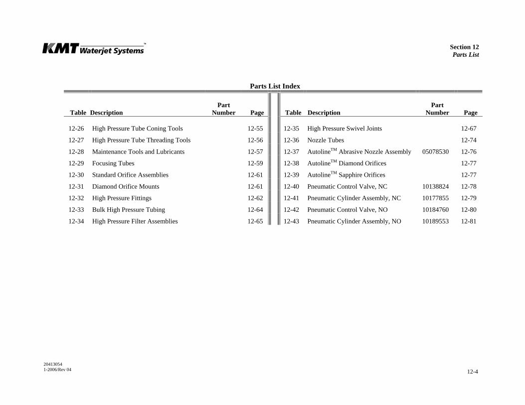
Section 12 Parts List
20413054 1-2006/Rev 04 12-4
Parts List Index
Table
Description
Part Number
Page
Table
Description
Part Number
Page
12-26 High Pressure Tube Coning Tools 12-55 12-35 High Pressure Swivel Joints 12-67
12-27 High Pressure Tube Threading Tools 12-56 12-36 Nozzle Tubes 12-74
12-28 Maintenance Tools and Lubricants 12-57 12-37 AutolineTM Abrasive Nozzle Assembly 05078530 12-76
12-29 Focusing Tubes 12-59 12-38 AutolineTM Diamond Orifices 12-77
12-30 Standard Orifice Assemblies 12-61 12-39 AutolineTM Sapphire Orifices 12-77
12-31 Diamond Orifice Mounts 12-61 12-40 Pneumatic Control Valve, NC 10138824 12-78
12-32 High Pressure Fittings 12-62 12-41 Pneumatic Cylinder Assembly, NC 10177855 12-79
12-33 Bulk High Pressure Tubing 12-64 12-42 Pneumatic Control Valve, NO 10184760 12-80
12-34 High Pressure Filter Assemblies 12-65 12-43 Pneumatic Cylinder Assembly, NO 10189553 12-81

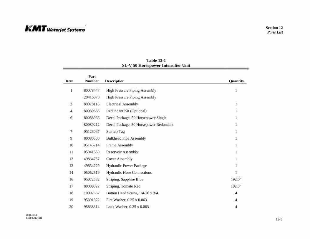
Section 12 Parts List
20413054 1-2006/Rev 04 12-5
Table 12-1 SL-V 50 Horsepower Intensifier Unit
Item
Part Number
Description
Quantity
1 80078447 High Pressure Piping Assembly 1
20415070 High Pressure Piping Assembly
2 80078116 Electrical Assembly 1
4 80080666 Redundant Kit (Optional) 1
6 80088966 Decal Package, 50 Horsepower Single 1
80089212 Decal Package, 50 Horsepower Redundant 1
7 05128087 Startup Tag 1
9 80080500 Bulkhead Pipe Assembly 1
10 05143714 Frame Assembly 1
11 05041660 Reservoir Assembly 1
12 49834757 Cover Assembly 1
13 49834229 Hydraulic Power Package 1
14 05052519 Hydraulic Hose Connections 1
16 05072582 Striping, Sapphire Blue 192.0”
17 80089022 Striping, Tomato Red 192.0”
18 10097657 Button Head Screw, 1/4-20 x 3/4 4
19 95391322 Flat Washer, 0.25 x 0.063 4
20 95838314 Lock Washer, 0.25 x 0.063 4
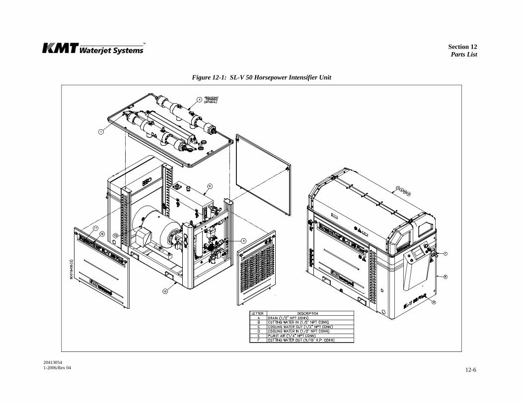
Section 12 Parts List
20413054 1-2006/Rev 04 12-6
Figure 12-1: SL-V 50 Horsepower Intensifier Unit
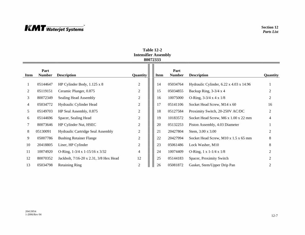
Section 12 Parts List
20413054 1-2006/Rev 04 12-7
Table 12-2 Intensifier Assembly
80072333
Item
Part Number
Description
Quantity
Item
Part Number
Description
Quantity
1 05144647 HP Cylinder Body, 1.125 x 8 2 14 05034764 Hydraulic Cylinder, 6.22 x 4.03 x 14.96 1
2 05119151 Ceramic Plunger, 0.875 2 15 05034855 Backup Ring, 3-3/4 x 4 2
3 80072349 Sealing Head Assembly 2 16 10075000 O-Ring, 3-3/4 x 4 x 1/8 2
4 05034772 Hydraulic Cylinder Head 2 17 05141106 Socket Head Screw, M14 x 60 16
5 05149703 HP Seal Assembly, 0.875 2 18 05127584 Proximity Switch, 20-250V AC/DC 2
6 05144696 Spacer, Sealing Head 2 19 10183572 Socket Head Screw, M6 x 1.00 x 22 mm 4
7 80073646 HP Cylinder Nut, HSEC 2 20 05132253 Piston Assembly, 4.03 Diameter 1
8 05130091 Hydraulic Cartridge Seal Assembly 2 21 20427804 Stem, 3.00 x 3.00 2
9 05007786 Bushing Retainer Flange 2 22 20427994 Socket Head Screw, M10 x 1.5 x 65 mm 8
10 20418805 Liner, HP Cylinder 2 23 05061486 Lock Washer, M10 8
11 10074920 O-Ring, 1-3/4 x 1-15/16 x 3/32 4 24 10074409 O-Ring, 1 x 1-1/4 x 1/8 2
12 80070352 Jackbolt, 7/16-20 x 2.31, 3/8 Hex Head 12 25 05144183 Spacer, Proximity Switch 2
13 05034798 Retaining Ring 2 26 05081872 Gasket, Stem/Upper Drip Pan 2
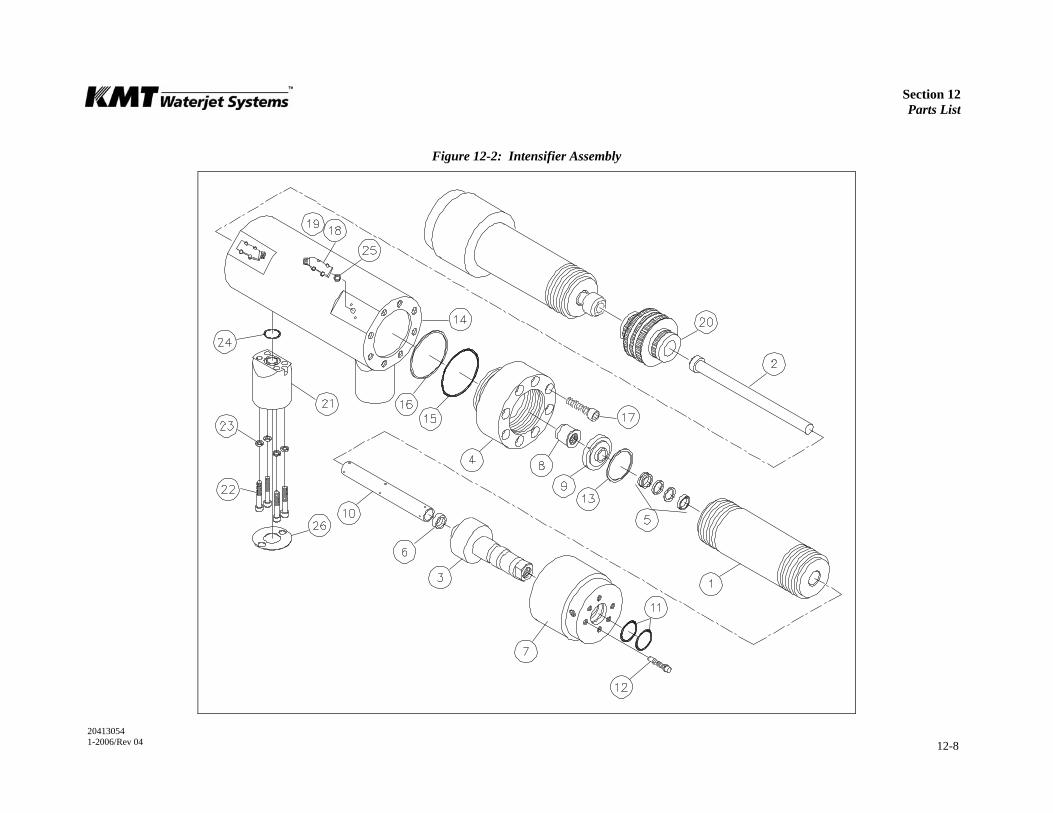
Section 12 Parts List
20413054 1-2006/Rev 04 12-8
Figure 12-2: Intensifier Assembly
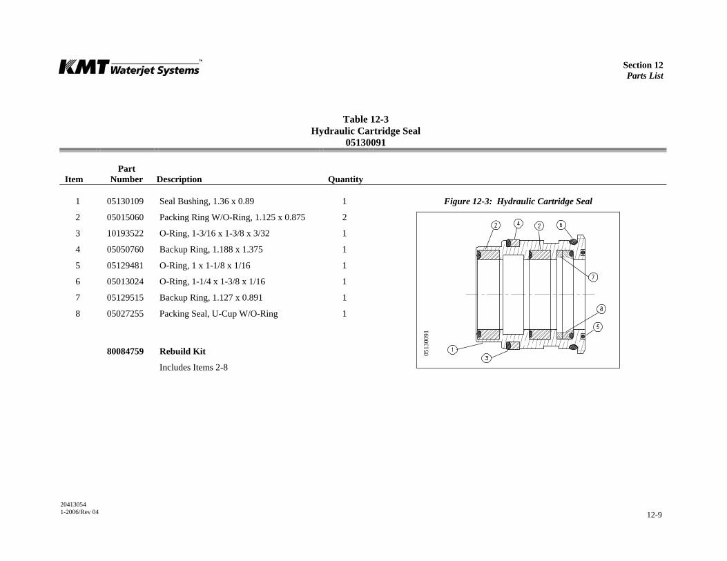
Section 12 Parts List
20413054 1-2006/Rev 04 12-9
Table 12-3 Hydraulic Cartridge Seal
05130091
Item
Part Number
Description
Quantity
1 05130109 Seal Bushing, 1.36 x 0.89 1 Figure 12-3: Hydraulic Cartridge Seal
2 05015060 Packing Ring W/O-Ring, 1.125 x 0.875 2
3 10193522 O-Ring, 1-3/16 x 1-3/8 x 3/32 1
4 05050760 Backup Ring, 1.188 x 1.375 1
5 05129481 O-Ring, 1 x 1-1/8 x 1/16 1
6 05013024 O-Ring, 1-1/4 x 1-3/8 x 1/16 1
7 05129515 Backup Ring, 1.127 x 0.891 1
8 05027255 Packing Seal, U-Cup W/O-Ring 1
80084759 Rebuild Kit
Includes Items 2-8
0513
0091
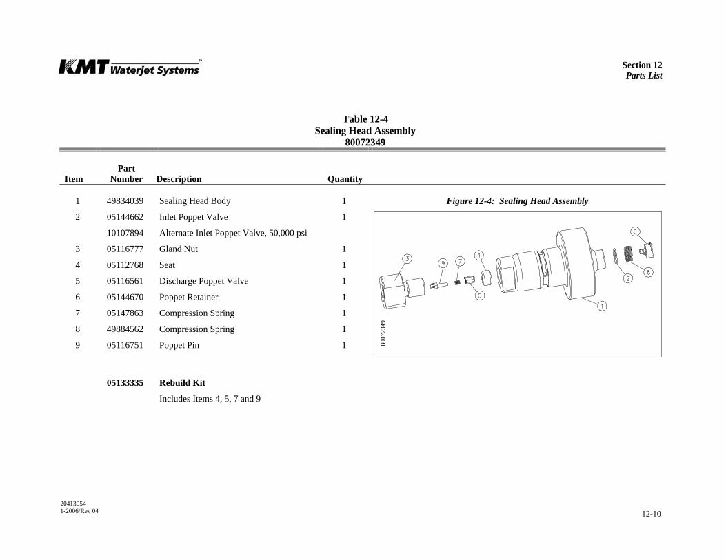
Section 12 Parts List
20413054 1-2006/Rev 04 12-10
Table 12-4 Sealing Head Assembly
80072349
Item
Part Number
Description
Quantity
1 49834039 Sealing Head Body 1 Figure 12-4: Sealing Head Assembly
2 05144662 Inlet Poppet Valve 1
10107894 Alternate Inlet Poppet Valve, 50,000 psi
3 05116777 Gland Nut 1
4 05112768 Seat 1
5 05116561 Discharge Poppet Valve 1
6 05144670 Poppet Retainer 1
7 05147863 Compression Spring 1
8 49884562 Compression Spring 1
9 05116751 Poppet Pin 1
05133335 Rebuild Kit
Includes Items 4, 5, 7 and 9
8007
2349
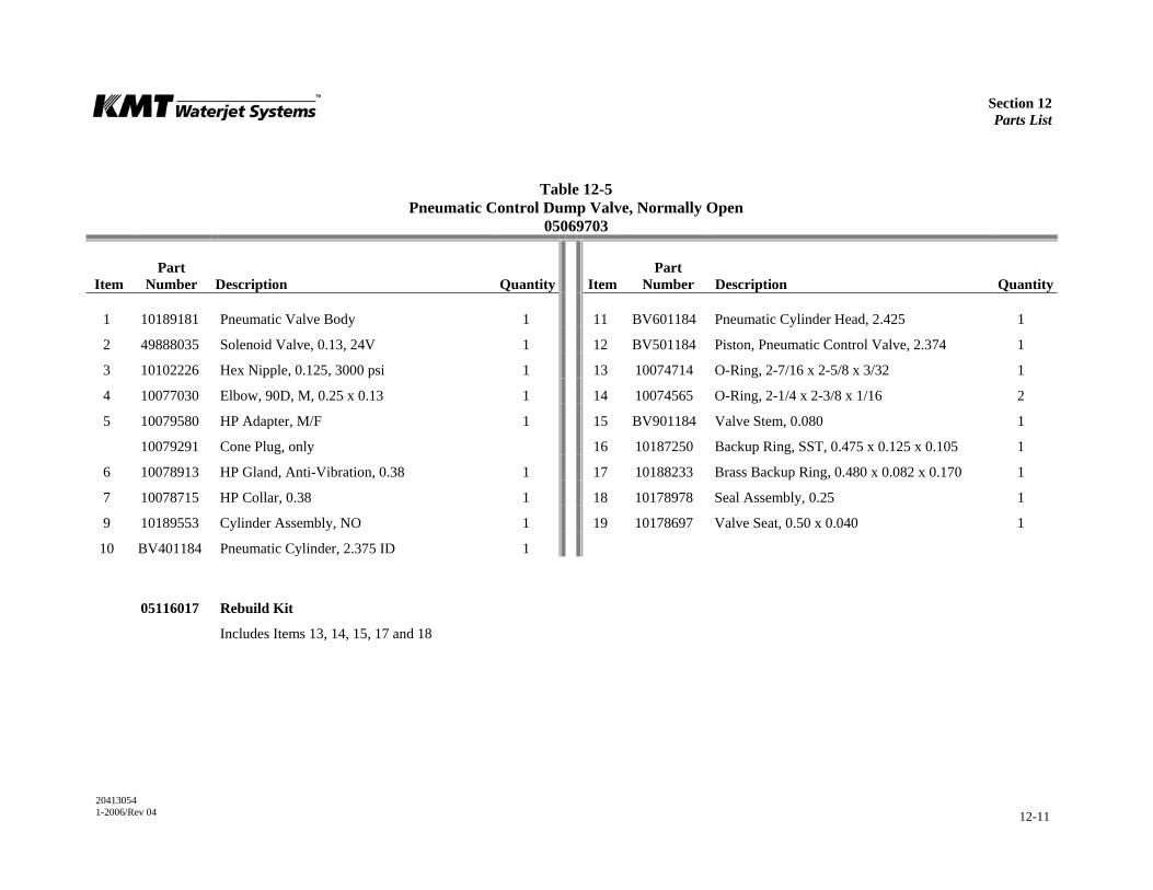
Section 12 Parts List
20413054 1-2006/Rev 04 12-11
Table 12-5 Pneumatic Control Dump Valve, Normally Open
05069703
Item
Part Number
Description
Quantity
Item
Part Number
Description
Quantity
1 10189181 Pneumatic Valve Body 1 11 BV601184 Pneumatic Cylinder Head, 2.425 1
2 49888035 Solenoid Valve, 0.13, 24V 1 12 BV501184 Piston, Pneumatic Control Valve, 2.374 1
3 10102226 Hex Nipple, 0.125, 3000 psi 1 13 10074714 O-Ring, 2-7/16 x 2-5/8 x 3/32 1
4 10077030 Elbow, 90D, M, 0.25 x 0.13 1 14 10074565 O-Ring, 2-1/4 x 2-3/8 x 1/16 2
5 10079580 HP Adapter, M/F 1 15 BV901184 Valve Stem, 0.080 1
10079291 Cone Plug, only 16 10187250 Backup Ring, SST, 0.475 x 0.125 x 0.105 1
6 10078913 HP Gland, Anti-Vibration, 0.38 1 17 10188233 Brass Backup Ring, 0.480 x 0.082 x 0.170 1
7 10078715 HP Collar, 0.38 1 18 10178978 Seal Assembly, 0.25 1
9 10189553 Cylinder Assembly, NO 1 19 10178697 Valve Seat, 0.50 x 0.040 1
10 BV401184 Pneumatic Cylinder, 2.375 ID 1
05116017 Rebuild Kit
Includes Items 13, 14, 15, 17 and 18

Section 12 Parts List
20413054 1-2006/Rev 04 12-12
Figure 12-5: Pneumatic Control Dump Valve
0506
9703
_1
0511
9581

Section 12 Parts List
20413054 1-2006/Rev 04 12-13
Table 12-6 Hydraulic Piston Assembly
05132253
Item
Part Number
Description
Quantity
1 05132261 Hydraulic Ram Piston, 4.03 1
2 05074380 Plunger Retainer Pin, Clevis, 0.25 x 0.43 12
3 05049887 Set Screw, Socket, 3/8-16 x 3/8 2
4 10148757 Check Valve Cartridge W/O-Ring 2
5 49877509 Adhesive, Thread Locker --
6 05088364 Flat Snap Ring, 0.032 x 0.375 x 2.010 2
7 05049994 Backup Ring, 1.50 x 1.25 2
8 05087713 O-Ring, 1-1/4 x 1-1/2 x 1/8 2
9 05117965 Seal Assembly, Hydraulic Piston 1
10 05117940 Bearing Ring, Hydraulic Piston 2
05115951 Rebuild Kit
Includes Items 4, 6, 7, 8,9 and 10
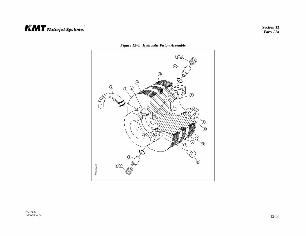
Section 12 Parts List
20413054 1-2006/Rev 04 12-14
Figure 12-6: Hydraulic Piston Assembly
0513
2253
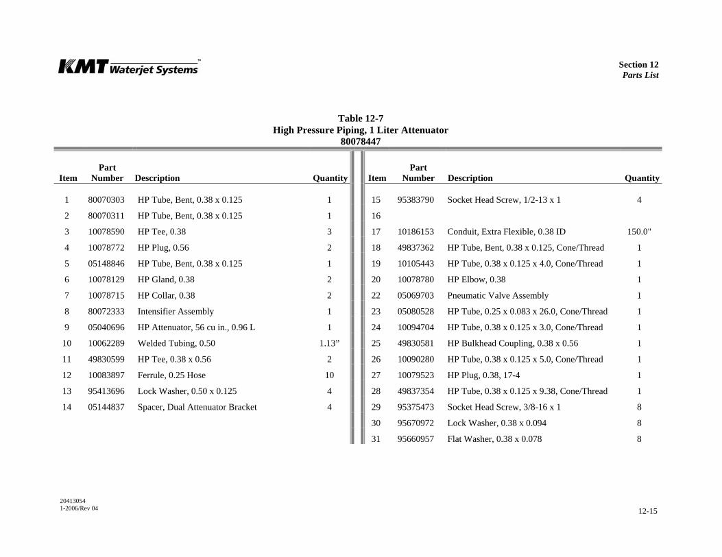
Section 12 Parts List
20413054 1-2006/Rev 04 12-15
Table 12-7 High Pressure Piping, 1 Liter Attenuator
80078447
Item
Part Number
Description
Quantity
Item
Part Number
Description
Quantity
1 80070303 HP Tube, Bent, 0.38 x 0.125 1 15 95383790 Socket Head Screw, 1/2-13 x 1 4
2 80070311 HP Tube, Bent, 0.38 x 0.125 1 16
3 10078590 HP Tee, 0.38 3 17 10186153 Conduit, Extra Flexible, 0.38 ID 150.0"
4 10078772 HP Plug, 0.56 2 18 49837362 HP Tube, Bent, 0.38 x 0.125, Cone/Thread 1
5 05148846 HP Tube, Bent, 0.38 x 0.125 1 19 10105443 HP Tube, 0.38 x 0.125 x 4.0, Cone/Thread 1
6 10078129 HP Gland, 0.38 2 20 10078780 HP Elbow, 0.38 1
7 10078715 HP Collar, 0.38 2 22 05069703 Pneumatic Valve Assembly 1
8 80072333 Intensifier Assembly 1 23 05080528 HP Tube, 0.25 x 0.083 x 26.0, Cone/Thread 1
9 05040696 HP Attenuator, 56 cu in., 0.96 L 1 24 10094704 HP Tube, 0.38 x 0.125 x 3.0, Cone/Thread 1
10 10062289 Welded Tubing, 0.50 1.13” 25 49830581 HP Bulkhead Coupling, 0.38 x 0.56 1
11 49830599 HP Tee, 0.38 x 0.56 2 26 10090280 HP Tube, 0.38 x 0.125 x 5.0, Cone/Thread 1
12 10083897 Ferrule, 0.25 Hose 10 27 10079523 HP Plug, 0.38, 17-4 1
13 95413696 Lock Washer, 0.50 x 0.125 4 28 49837354 HP Tube, 0.38 x 0.125 x 9.38, Cone/Thread 1
14 05144837 Spacer, Dual Attenuator Bracket 4 29 95375473 Socket Head Screw, 3/8-16 x 1 8
30 95670972 Lock Washer, 0.38 x 0.094 8
31 95660957 Flat Washer, 0.38 x 0.078 8
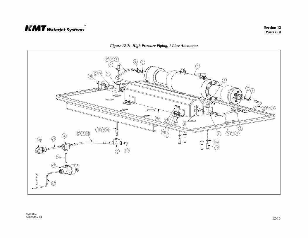
Section 12 Parts List
20413054 1-2006/Rev 04 12-16
Figure 12-7: High Pressure Piping, 1 Liter Attenuator
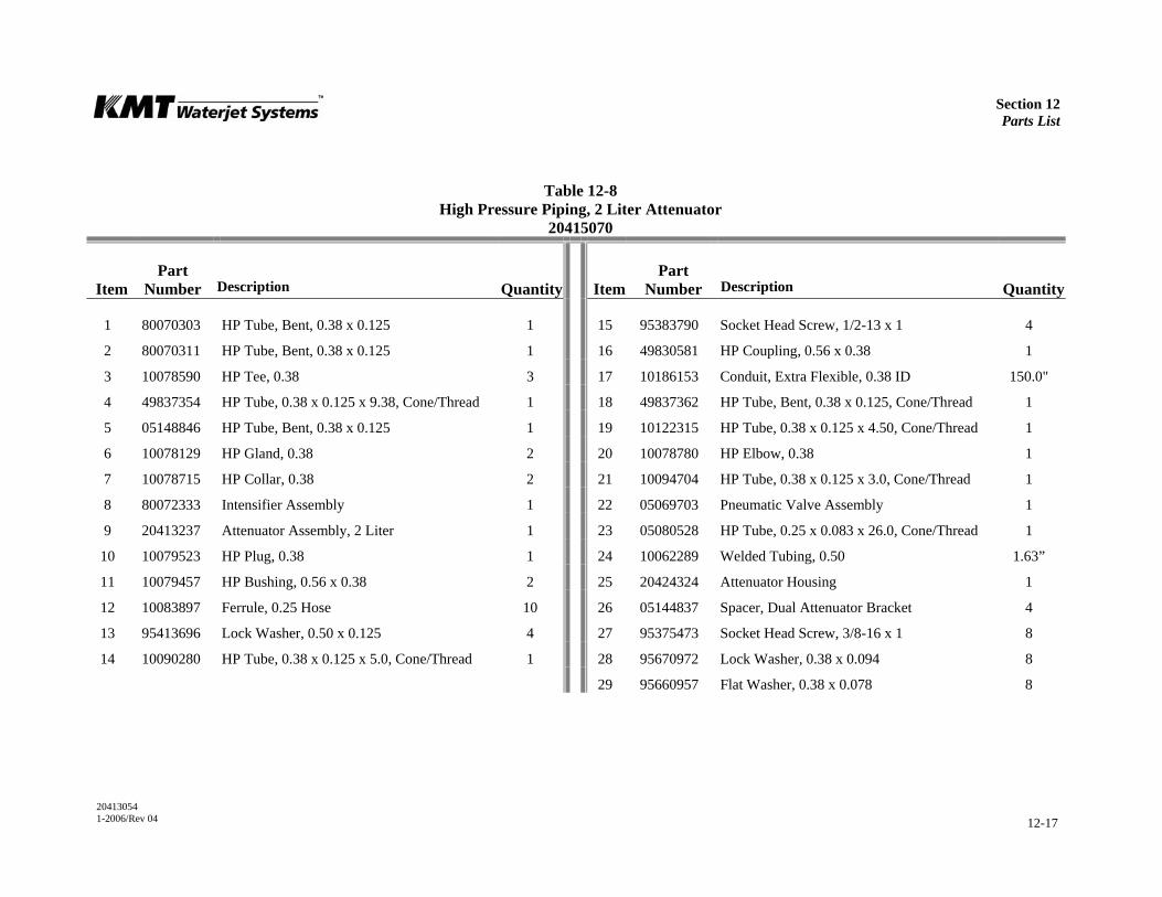
Section 12 Parts List
20413054 1-2006/Rev 04 12-17
Table 12-8 High Pressure Piping, 2 Liter Attenuator
20415070
Item
Part Number
Description
Quantity
Item
Part Number
Description
Quantity
1 80070303 HP Tube, Bent, 0.38 x 0.125 1 15 95383790 Socket Head Screw, 1/2-13 x 1 4
2 80070311 HP Tube, Bent, 0.38 x 0.125 1 16 49830581 HP Coupling, 0.56 x 0.38 1
3 10078590 HP Tee, 0.38 3 17 10186153 Conduit, Extra Flexible, 0.38 ID 150.0"
4 49837354 HP Tube, 0.38 x 0.125 x 9.38, Cone/Thread 1 18 49837362 HP Tube, Bent, 0.38 x 0.125, Cone/Thread 1
5 05148846 HP Tube, Bent, 0.38 x 0.125 1 19 10122315 HP Tube, 0.38 x 0.125 x 4.50, Cone/Thread 1
6 10078129 HP Gland, 0.38 2 20 10078780 HP Elbow, 0.38 1
7 10078715 HP Collar, 0.38 2 21 10094704 HP Tube, 0.38 x 0.125 x 3.0, Cone/Thread 1
8 80072333 Intensifier Assembly 1 22 05069703 Pneumatic Valve Assembly 1
9 20413237 Attenuator Assembly, 2 Liter 1 23 05080528 HP Tube, 0.25 x 0.083 x 26.0, Cone/Thread 1
10 10079523 HP Plug, 0.38 1 24 10062289 Welded Tubing, 0.50 1.63”
11 10079457 HP Bushing, 0.56 x 0.38 2 25 20424324 Attenuator Housing 1
12 10083897 Ferrule, 0.25 Hose 10 26 05144837 Spacer, Dual Attenuator Bracket 4
13 95413696 Lock Washer, 0.50 x 0.125 4 27 95375473 Socket Head Screw, 3/8-16 x 1 8
14 10090280 HP Tube, 0.38 x 0.125 x 5.0, Cone/Thread 1 28 95670972 Lock Washer, 0.38 x 0.094 8
29 95660957 Flat Washer, 0.38 x 0.078 8

Section 12 Parts List
20413054 1-2006/Rev 04 12-18
Figure 12-8: High Pressure Piping, 2 Liter Attenuator
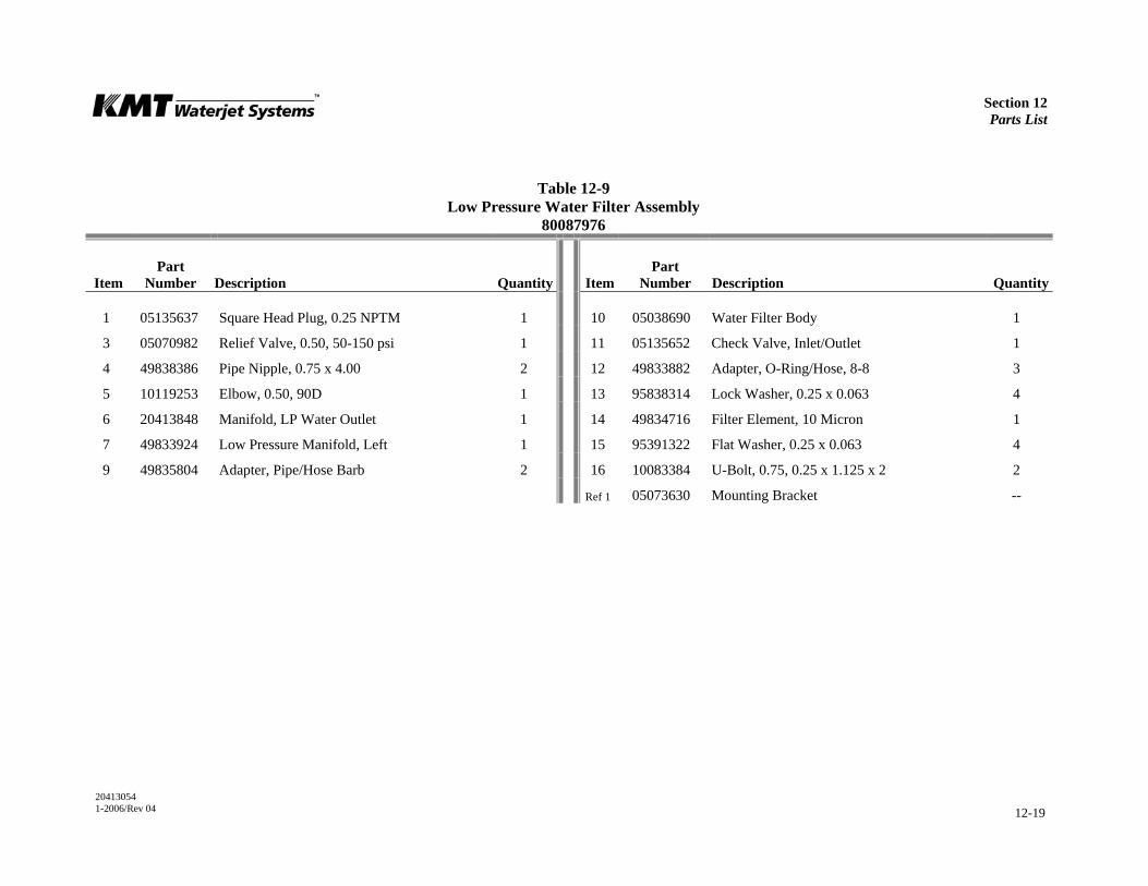
Section 12 Parts List
20413054 1-2006/Rev 04 12-19
Table 12-9 Low Pressure Water Filter Assembly
80087976
Item
Part Number
Description
Quantity
Item
Part Number
Description
Quantity
1 05135637 Square Head Plug, 0.25 NPTM 1 10 05038690 Water Filter Body 1
3 05070982 Relief Valve, 0.50, 50-150 psi 1 11 05135652 Check Valve, Inlet/Outlet 1
4 49838386 Pipe Nipple, 0.75 x 4.00 2 12 49833882 Adapter, O-Ring/Hose, 8-8 3
5 10119253 Elbow, 0.50, 90D 1 13 95838314 Lock Washer, 0.25 x 0.063 4
6 20413848 Manifold, LP Water Outlet 1 14 49834716 Filter Element, 10 Micron 1
7 49833924 Low Pressure Manifold, Left 1 15 95391322 Flat Washer, 0.25 x 0.063 4
9 49835804 Adapter, Pipe/Hose Barb 2 16 10083384 U-Bolt, 0.75, 0.25 x 1.125 x 2 2
Ref 1 05073630 Mounting Bracket --

Section 12 Parts List
20413054 1-2006/Rev 04 12-20
Figure 12-9: Low Pressure Water Filter Assembly

Section 12 Parts List
20413054 1-2006/Rev 04 12-21
Table 12-10 Hydraulic Power Package
49834229
Item
Part Number
Description
Quantity
1 80087935 Motor/Pump Assembly, 50 HP 1
2 05049168 Adapter, Water Pump 1
3 95572897 Hex Head Screw, 1/4-20 x 5/8 3
4 95838314 Lock Washer, 0.25 x 0.063 3
5 49887094 Water Pump, Vane, 200 psi 1
6 10092302 Shaft Coupling, 0.63 1
7 10116952 Cap Plug, 1.04 x 0.855 2
8 95750394 Lock Washer, 0.38 x 0.094 2
9 95416319 Hex Head Screw, 3/8-16 x 1 2
10 10091510 Arrow Decal 1
11 05092523 Directional Control Valve 1
12 95055026 Socket Head Screw, 1/2-13 x 1-3/4 6
13 95688750 Lock Washer, 0.50 x 0.172 6
14 10069714 Flat Washer, 0.38 x 0.078 2
15 05071717 Relief Valve, 235 Bar 1
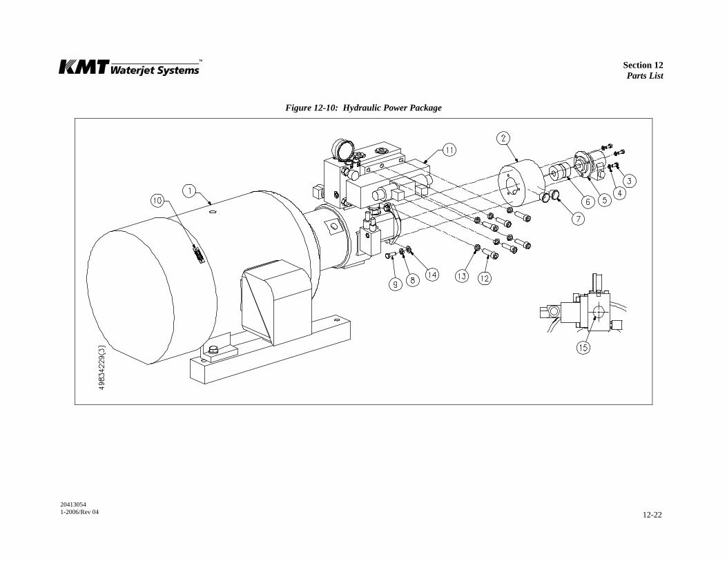
Section 12 Parts List
20413054 1-2006/Rev 04 12-22
Figure 12-10: Hydraulic Power Package
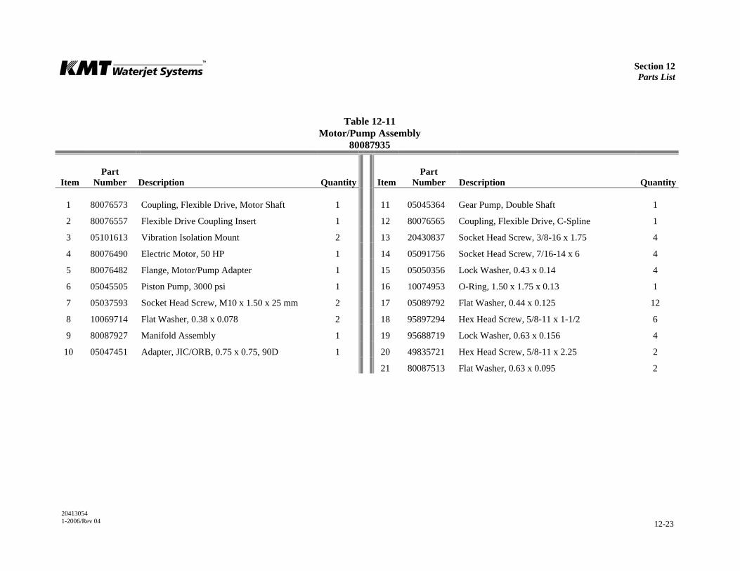
Section 12 Parts List
20413054 1-2006/Rev 04 12-23
Table 12-11 Motor/Pump Assembly
80087935
Item
Part Number
Description
Quantity
Item
Part Number
Description
Quantity
1 80076573 Coupling, Flexible Drive, Motor Shaft 1 11 05045364 Gear Pump, Double Shaft 1
2 80076557 Flexible Drive Coupling Insert 1 12 80076565 Coupling, Flexible Drive, C-Spline 1
3 05101613 Vibration Isolation Mount 2 13 20430837 Socket Head Screw, 3/8-16 x 1.75 4
4 80076490 Electric Motor, 50 HP 1 14 05091756 Socket Head Screw, 7/16-14 x 6 4
5 80076482 Flange, Motor/Pump Adapter 1 15 05050356 Lock Washer, 0.43 x 0.14 4
6 05045505 Piston Pump, 3000 psi 1 16 10074953 O-Ring, 1.50 x 1.75 x 0.13 1
7 05037593 Socket Head Screw, M10 x 1.50 x 25 mm 2 17 05089792 Flat Washer, 0.44 x 0.125 12
8 10069714 Flat Washer, 0.38 x 0.078 2 18 95897294 Hex Head Screw, 5/8-11 x 1-1/2 6
9 80087927 Manifold Assembly 1 19 95688719 Lock Washer, 0.63 x 0.156 4
10 05047451 Adapter, JIC/ORB, 0.75 x 0.75, 90D 1 20 49835721 Hex Head Screw, 5/8-11 x 2.25 2
21 80087513 Flat Washer, 0.63 x 0.095 2
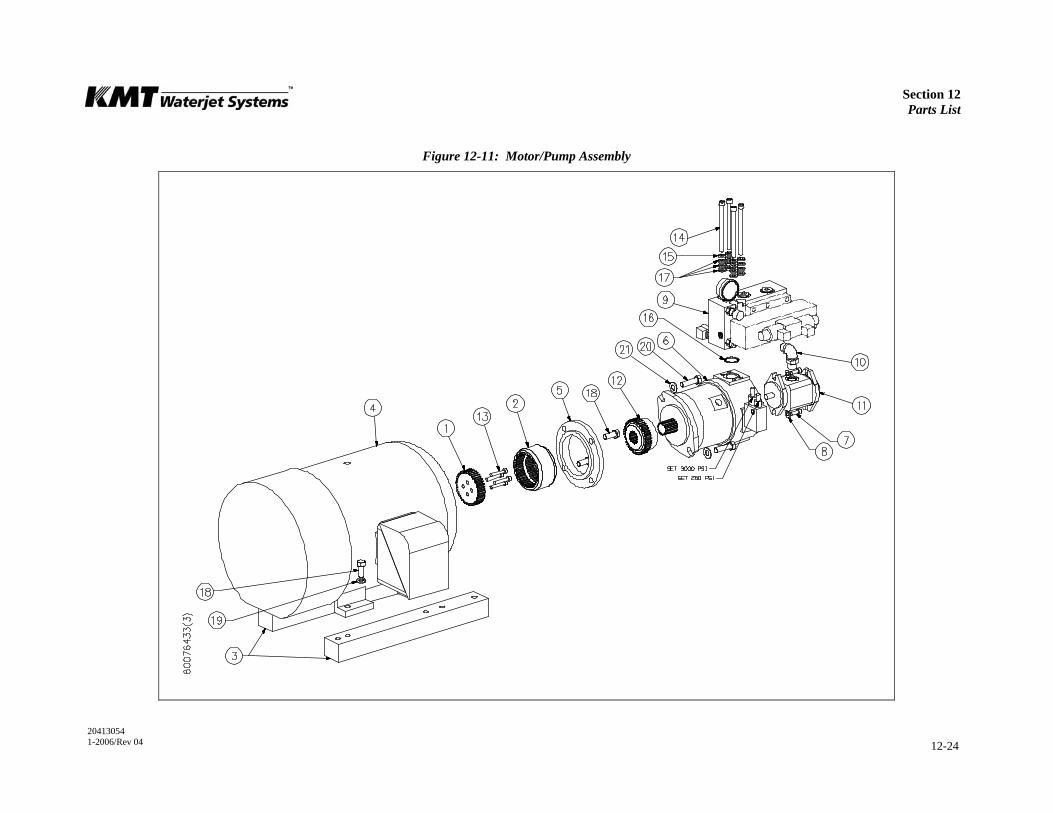
Section 12 Parts List
20413054 1-2006/Rev 04 12-24
Figure 12-11: Motor/Pump Assembly
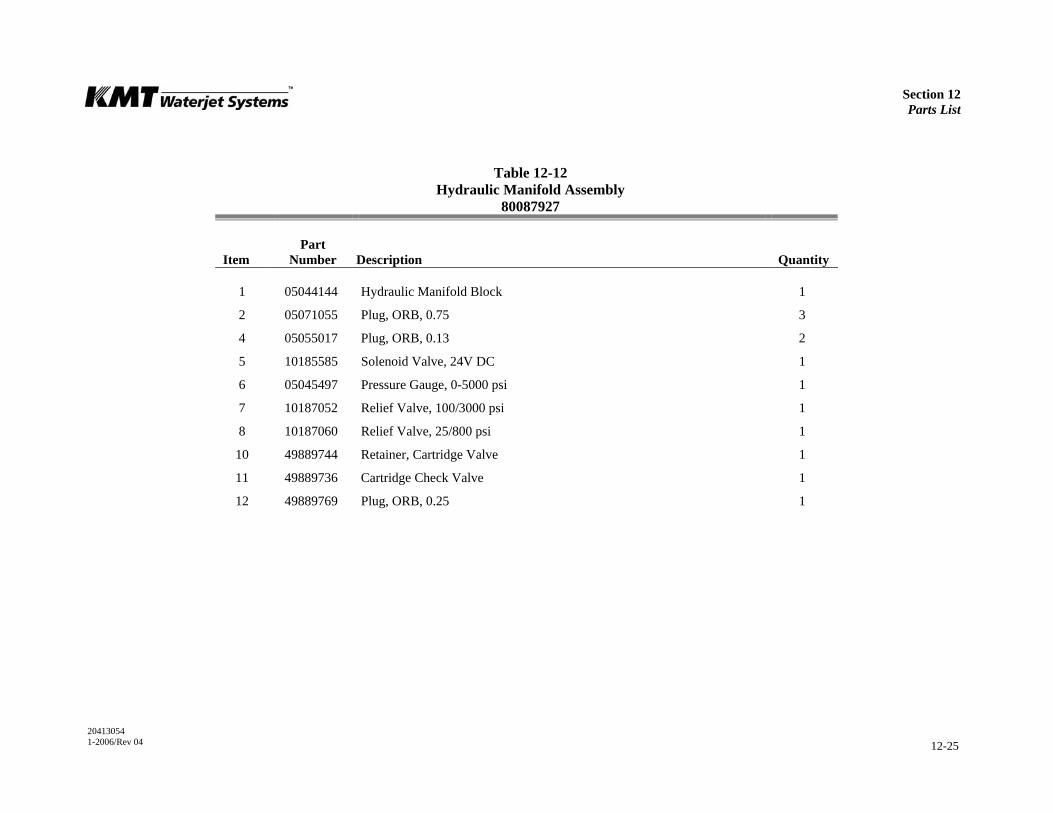
Section 12 Parts List
20413054 1-2006/Rev 04 12-25
Table 12-12 Hydraulic Manifold Assembly
80087927
Item
Part Number
Description
Quantity
1 05044144 Hydraulic Manifold Block 1
2 05071055 Plug, ORB, 0.75 3
4 05055017 Plug, ORB, 0.13 2
5 10185585 Solenoid Valve, 24V DC 1
6 05045497 Pressure Gauge, 0-5000 psi 1
7 10187052 Relief Valve, 100/3000 psi 1
8 10187060 Relief Valve, 25/800 psi 1
10 49889744 Retainer, Cartridge Valve 1
11 49889736 Cartridge Check Valve 1
12 49889769 Plug, ORB, 0.25 1

Section 12 Parts List
20413054 1-2006/Rev 04 12-26
Figure 12-12: Hydraulic Manifold Assembly

Section 12 Parts List
20413054 1-2006/Rev 04 12-27
Table 12-13 Hydraulic Hose Connections
05052519
Item
Part Number
Description
Quantity
Item
Part Number
Description
Quantity
1 05060744 Hydraulic Hose Assembly, 0.75, 0.75F JIC 1 11 05071105 Hydraulic Hose Assembly, 0.75, 0.75, JIC 2
2 05049705 Hydraulic Hose Assembly, 0.75, 0.75F, JIC 1 12 05071121 Hydraulic Hose Assembly, 0.25, 0.25F, JIC 1
3 05049739 Hydraulic Hose Assembly, 0.75, 0.75F, JIC 1 13 05052493 Adapter, JIC/ORB, 0.75 x 0.63, 45D 2
4 10083517 Hose Clamp, 1.81-2.75 2 14 95702619 Adapter, JIC/ORB, 0.75 x 0.75 2
5 10179018 Radiator Hose, 2.0" 6.31" 15 10142644 Adapter, JIC/ORB, 0.25 x 0.25, 90D 3
6 05048780 Split Flange Kit, 2.0" 1 16 10144749 Adapter, JIC/ORB, 0.25 x 0.25, -Ring, 45D 1
7 05048806 Adapter, Hose/Flange, 2.0 x 2.0 1 17 05071113 Adapter, JIC/ORB, 0.75 x 0.75 1
8 05051214 Hydraulic Hose Assembly, 0.25, 0.25F, JIC 1 18 05050331 Adapter, JIC/ORB, 0.75 x 0.63, 90D 1
9 05060751 Hydraulic Hose Assembly, 0.25, 0.25F, JIC 1 19 10142594 Adapter, JIC/ORB, 1.0 x 0.75 1
10 05049713 Hydraulic Hose Assembly, 0.75, 0.75F, JIC 2 20 05060777 Elbow, JIC, 0.75 x 0.75, 45D 1
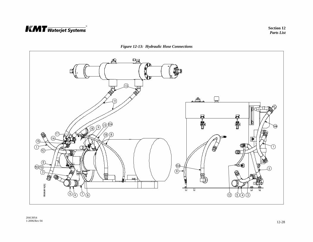
Section 12 Parts List
20413054 1-2006/Rev 04 12-28
Figure 12-13: Hydraulic Hose Connections
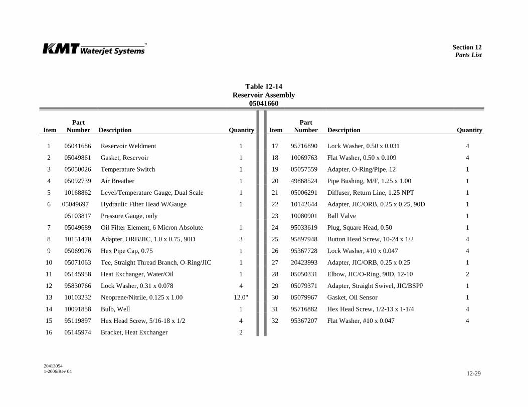
Section 12 Parts List
20413054 1-2006/Rev 04 12-29
Table 12-14 Reservoir Assembly
05041660
Item
Part Number
Description
Quantity
Item
Part Number
Description
Quantity
1 05041686 Reservoir Weldment 1 17 95716890 Lock Washer, 0.50 x 0.031 4
2 05049861 Gasket, Reservoir 1 18 10069763 Flat Washer, 0.50 x 0.109 4
3 05050026 Temperature Switch 1 19 05057559 Adapter, O-Ring/Pipe, 12 1
4 05092739 Air Breather 1 20 49868524 Pipe Bushing, M/F, 1.25 x 1.00 1
5 10168862 Level/Temperature Gauge, Dual Scale 1 21 05006291 Diffuser, Return Line, 1.25 NPT 1
6 05049697 Hydraulic Filter Head W/Gauge 1 22 10142644 Adapter, JIC/ORB, 0.25 x 0.25, 90D 1
05103817 Pressure Gauge, only 23 10080901 Ball Valve 1
7 05049689 Oil Filter Element, 6 Micron Absolute 1 24 95033619 Plug, Square Head, 0.50 1
8 10151470 Adapter, ORB/JIC, 1.0 x 0.75, 90D 3 25 95897948 Button Head Screw, 10-24 x 1/2 4
9 05069976 Hex Pipe Cap, 0.75 1 26 95367728 Lock Washer, #10 x 0.047 4
10 05071063 Tee, Straight Thread Branch, O-Ring/JIC 1 27 20423993 Adapter, JIC/ORB, 0.25 x 0.25 1
11 05145958 Heat Exchanger, Water/Oil 1 28 05050331 Elbow, JIC/O-Ring, 90D, 12-10 2
12 95830766 Lock Washer, 0.31 x 0.078 4 29 05079371 Adapter, Straight Swivel, JIC/BSPP 1
13 10103232 Neoprene/Nitrile, 0.125 x 1.00 12.0" 30 05079967 Gasket, Oil Sensor 1
14 10091858 Bulb, Well 1 31 95716882 Hex Head Screw, 1/2-13 x 1-1/4 4
15 95119897 Hex Head Screw, 5/16-18 x 1/2 4 32 95367207 Flat Washer, #10 x 0.047 4
16 05145974 Bracket, Heat Exchanger 2
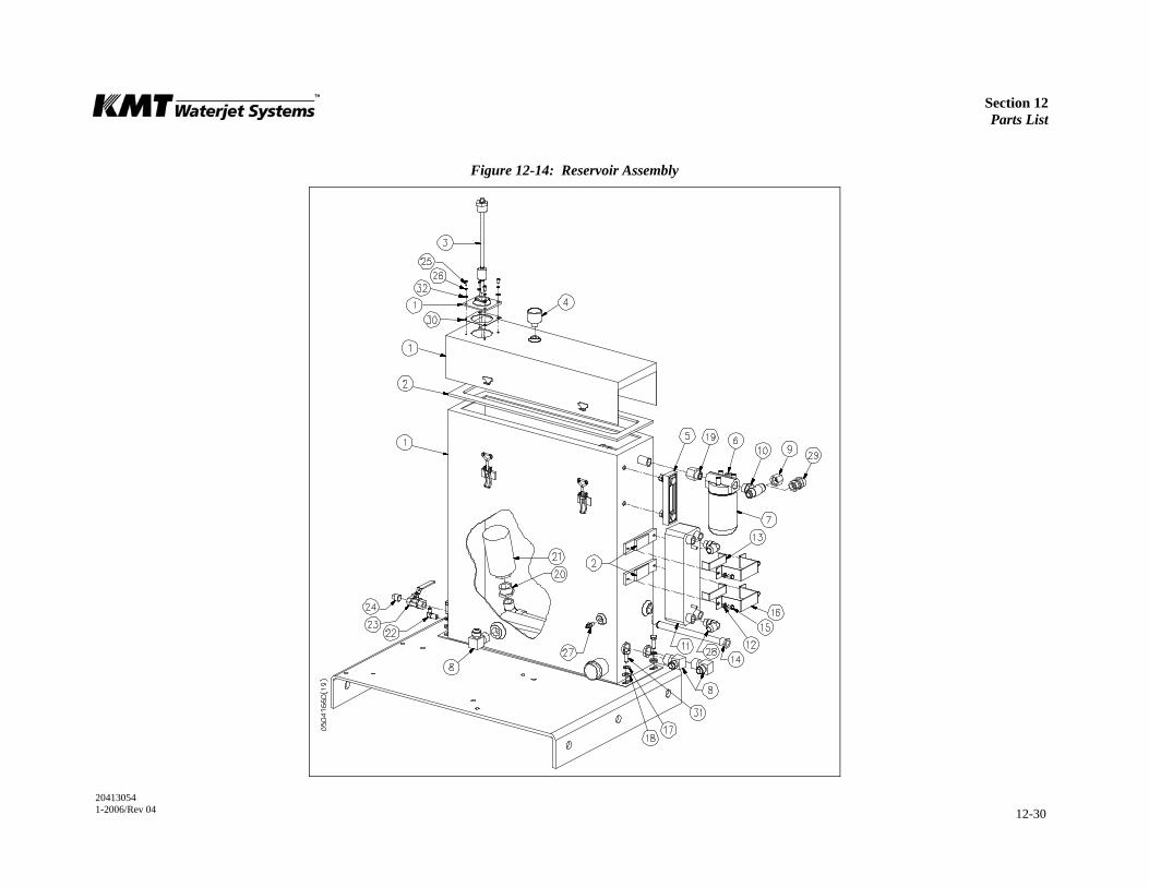
Section 12 Parts List
20413054 1-2006/Rev 04 12-30
Figure 12-14: Reservoir Assembly
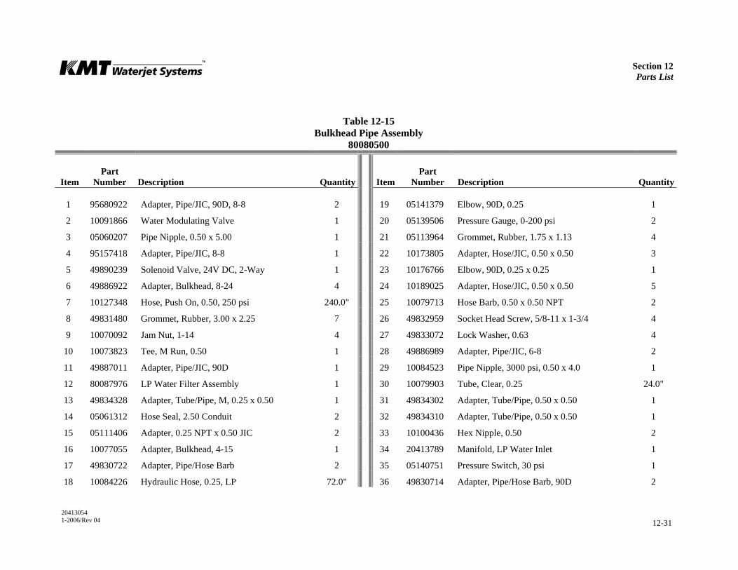
Section 12 Parts List
20413054 1-2006/Rev 04 12-31
Table 12-15 Bulkhead Pipe Assembly
80080500
Item
Part Number
Description
Quantity
Item
Part Number
Description
Quantity
1 95680922 Adapter, Pipe/JIC, 90D, 8-8 2 19 05141379 Elbow, 90D, 0.25 1
2 10091866 Water Modulating Valve 1 20 05139506 Pressure Gauge, 0-200 psi 2
3 05060207 Pipe Nipple, 0.50 x 5.00 1 21 05113964 Grommet, Rubber, 1.75 x 1.13 4
4 95157418 Adapter, Pipe/JIC, 8-8 1 22 10173805 Adapter, Hose/JIC, 0.50 x 0.50 3
5 49890239 Solenoid Valve, 24V DC, 2-Way 1 23 10176766 Elbow, 90D, 0.25 x 0.25 1
6 49886922 Adapter, Bulkhead, 8-24 4 24 10189025 Adapter, Hose/JIC, 0.50 x 0.50 5
7 10127348 Hose, Push On, 0.50, 250 psi 240.0" 25 10079713 Hose Barb, 0.50 x 0.50 NPT 2
8 49831480 Grommet, Rubber, 3.00 x 2.25 7 26 49832959 Socket Head Screw, 5/8-11 x 1-3/4 4
9 10070092 Jam Nut, 1-14 4 27 49833072 Lock Washer, 0.63 4
10 10073823 Tee, M Run, 0.50 1 28 49886989 Adapter, Pipe/JIC, 6-8 2
11 49887011 Adapter, Pipe/JIC, 90D 1 29 10084523 Pipe Nipple, 3000 psi, 0.50 x 4.0 1
12 80087976 LP Water Filter Assembly 1 30 10079903 Tube, Clear, 0.25 24.0"
13 49834328 Adapter, Tube/Pipe, M, 0.25 x 0.50 1 31 49834302 Adapter, Tube/Pipe, 0.50 x 0.50 1
14 05061312 Hose Seal, 2.50 Conduit 2 32 49834310 Adapter, Tube/Pipe, 0.50 x 0.50 1
15 05111406 Adapter, 0.25 NPT x 0.50 JIC 2 33 10100436 Hex Nipple, 0.50 2
16 10077055 Adapter, Bulkhead, 4-15 1 34 20413789 Manifold, LP Water Inlet 1
17 49830722 Adapter, Pipe/Hose Barb 2 35 05140751 Pressure Switch, 30 psi 1
18 10084226 Hydraulic Hose, 0.25, LP 72.0" 36 49830714 Adapter, Pipe/Hose Barb, 90D 2
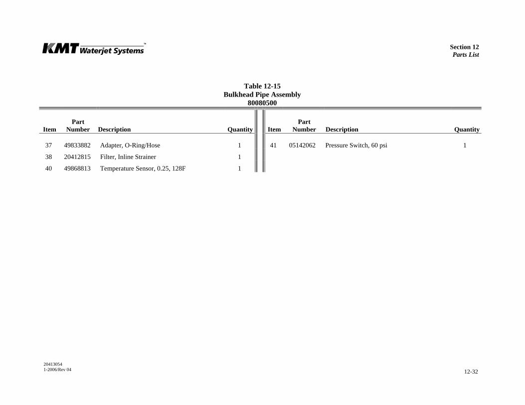
Section 12 Parts List
20413054 1-2006/Rev 04 12-32
Table 12-15 Bulkhead Pipe Assembly
80080500
Item
Part Number
Description
Quantity
Item
Part Number
Description
Quantity
37 49833882 Adapter, O-Ring/Hose 1 41 05142062 Pressure Switch, 60 psi 1
38 20412815 Filter, Inline Strainer 1
40 49868813 Temperature Sensor, 0.25, 128F 1
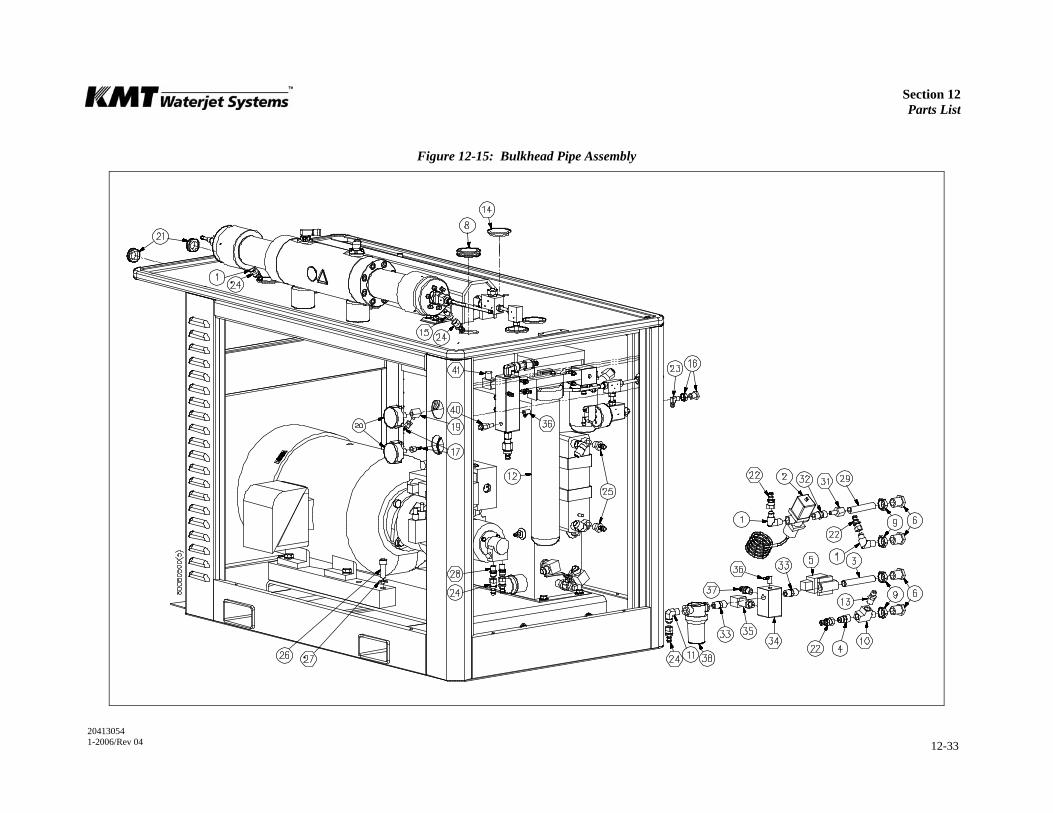
Section 12 Parts List
20413054 1-2006/Rev 04 12-33
Figure 12-15: Bulkhead Pipe Assembly


Section 12 Parts List
20413054 1-2006/Rev 04 12-34
Table 12-16 Cover Assembly
49834757
Item
Part Number
Description
Quantity
1 49834799 Support Assembly 1
2 49834773 Multi-Pin Hinge 1
3 49834724 Cover, Top 2
4 49834708 Cover, Left End 2
5 49834690 Cover, Right End 2
7 49837511 Mounting Bracket 4
8 49837529 Mounting Bracket 4
9 49837503 Spring, Gas 4
10 49837743 Flange Head Screw, Button Head, 3/8-16 x 1.0 32
11 05091988 Flange Nut, 3/8-16 32
12 95897948 Button Head Screw, 10-24 x 1/2 24
13 49832181 Flange Nut, #10-24 24
14 49837768 Gasket, Not Shown 1
15 95670972 Lock Washer, 0.38 x 0.094 6
16 05091954 Button Head Screw, 3/8-16 x 1.00 6
17 80076748 Cable, Lanyard, 18.75 4
18 49837826 Handle, Pocket Pull, Flush 4
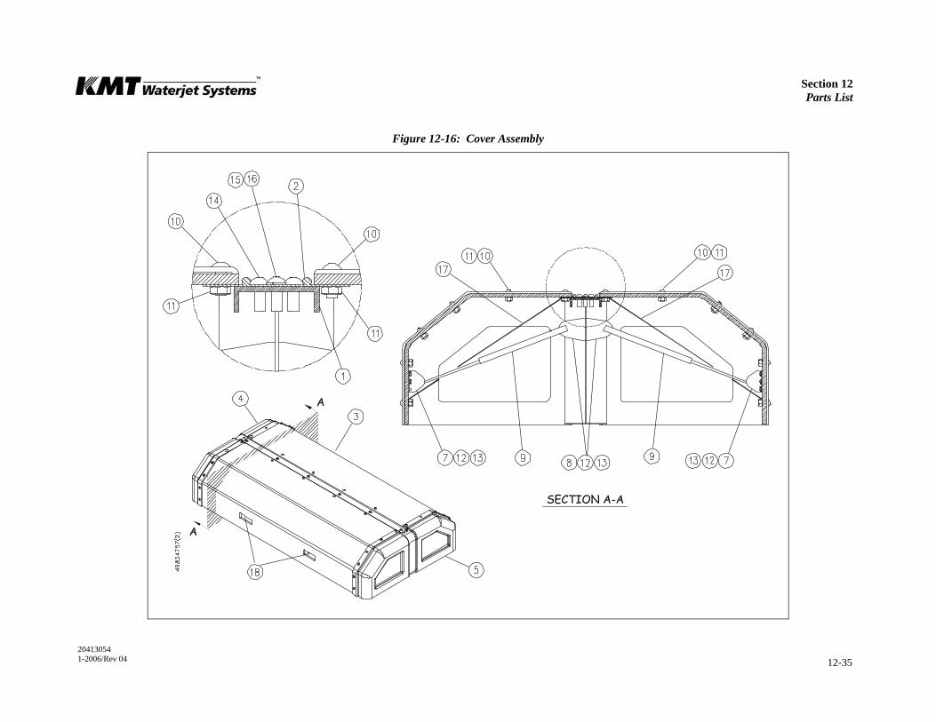
Section 12 Parts List
20413054 1-2006/Rev 04 12-35
Figure 12-16: Cover Assembly
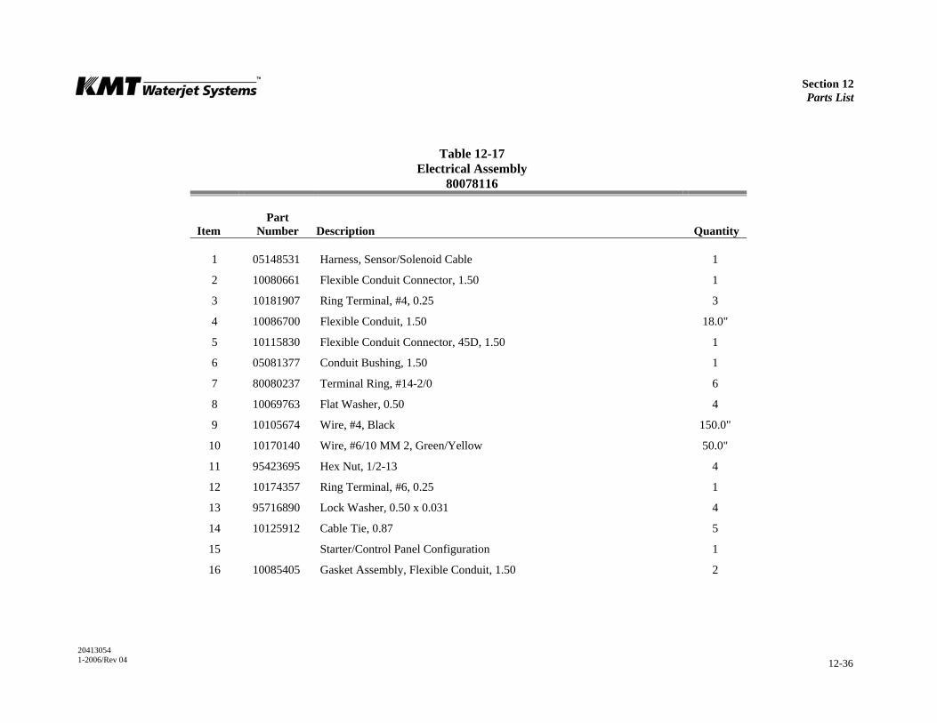
Section 12 Parts List
20413054 1-2006/Rev 04 12-36
Table 12-17 Electrical Assembly
80078116
Item
Part Number
Description
Quantity
1 05148531 Harness, Sensor/Solenoid Cable 1
2 10080661 Flexible Conduit Connector, 1.50 1
3 10181907 Ring Terminal, #4, 0.25 3
4 10086700 Flexible Conduit, 1.50 18.0"
5 10115830 Flexible Conduit Connector, 45D, 1.50 1
6 05081377 Conduit Bushing, 1.50 1
7 80080237 Terminal Ring, #14-2/0 6
8 10069763 Flat Washer, 0.50 4
9 10105674 Wire, #4, Black 150.0"
10 10170140 Wire, #6/10 MM 2, Green/Yellow 50.0"
11 95423695 Hex Nut, 1/2-13 4
12 10174357 Ring Terminal, #6, 0.25 1
13 95716890 Lock Washer, 0.50 x 0.031 4
14 10125912 Cable Tie, 0.87 5
15 Starter/Control Panel Configuration 1
16 10085405 Gasket Assembly, Flexible Conduit, 1.50 2
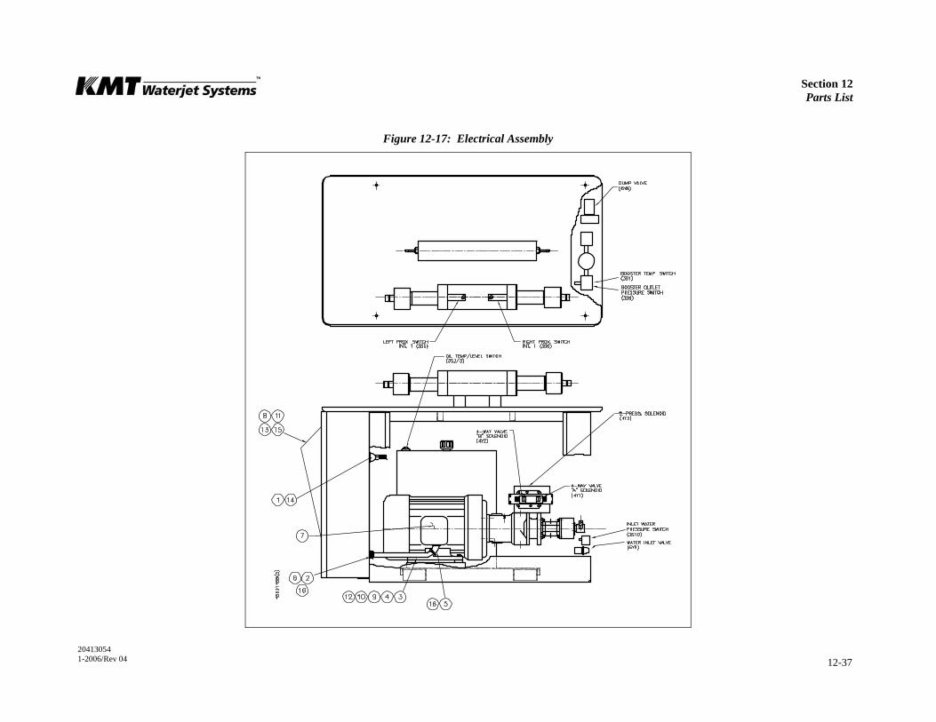
Section 12 Parts List
20413054 1-2006/Rev 04 12-37
Figure 12-17: Electrical Assembly
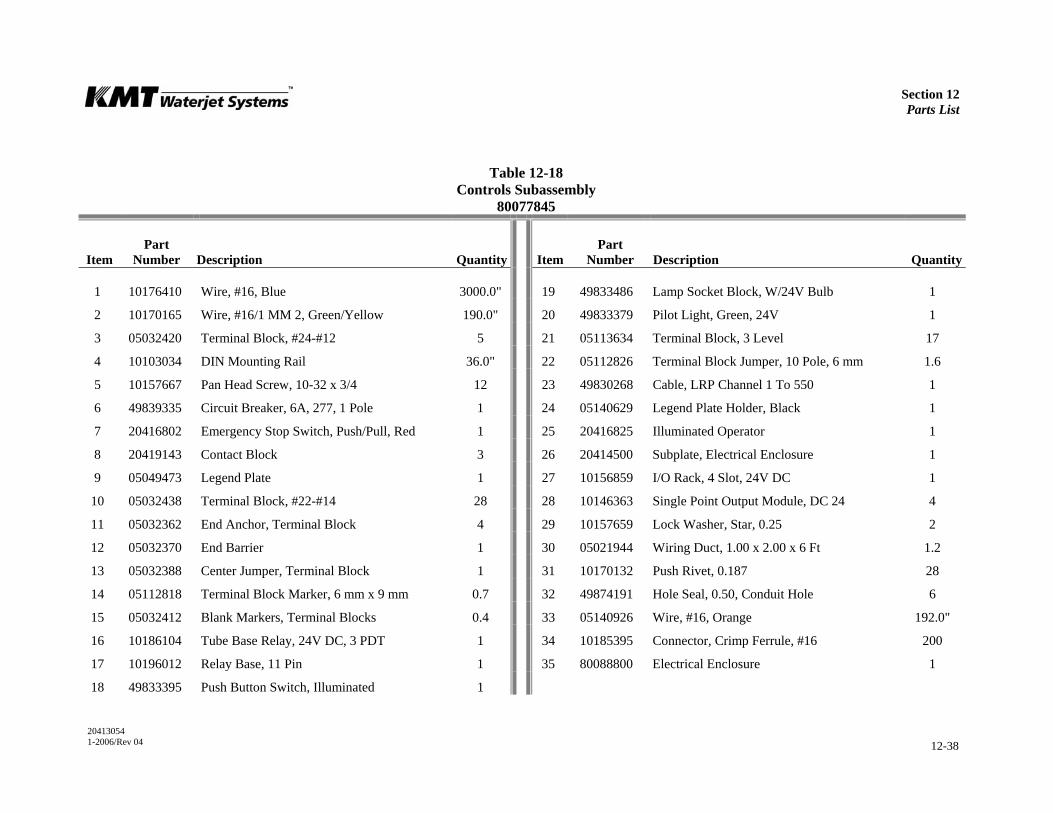
Section 12 Parts List
20413054 1-2006/Rev 04 12-38
Table 12-18 Controls Subassembly
80077845
Item
Part Number
Description
Quantity
Item
Part Number
Description
Quantity
1 10176410 Wire, #16, Blue 3000.0" 19 49833486 Lamp Socket Block, W/24V Bulb 1
2 10170165 Wire, #16/1 MM 2, Green/Yellow 190.0" 20 49833379 Pilot Light, Green, 24V 1
3 05032420 Terminal Block, #24-#12 5 21 05113634 Terminal Block, 3 Level 17
4 10103034 DIN Mounting Rail 36.0" 22 05112826 Terminal Block Jumper, 10 Pole, 6 mm 1.6
5 10157667 Pan Head Screw, 10-32 x 3/4 12 23 49830268 Cable, LRP Channel 1 To 550 1
6 49839335 Circuit Breaker, 6A, 277, 1 Pole 1 24 05140629 Legend Plate Holder, Black 1
7 20416802 Emergency Stop Switch, Push/Pull, Red 1 25 20416825 Illuminated Operator 1
8 20419143 Contact Block 3 26 20414500 Subplate, Electrical Enclosure 1
9 05049473 Legend Plate 1 27 10156859 I/O Rack, 4 Slot, 24V DC 1
10 05032438 Terminal Block, #22-#14 28 28 10146363 Single Point Output Module, DC 24 4
11 05032362 End Anchor, Terminal Block 4 29 10157659 Lock Washer, Star, 0.25 2
12 05032370 End Barrier 1 30 05021944 Wiring Duct, 1.00 x 2.00 x 6 Ft 1.2
13 05032388 Center Jumper, Terminal Block 1 31 10170132 Push Rivet, 0.187 28
14 05112818 Terminal Block Marker, 6 mm x 9 mm 0.7 32 49874191 Hole Seal, 0.50, Conduit Hole 6
15 05032412 Blank Markers, Terminal Blocks 0.4 33 05140926 Wire, #16, Orange 192.0"
16 10186104 Tube Base Relay, 24V DC, 3 PDT 1 34 10185395 Connector, Crimp Ferrule, #16 200
17 10196012 Relay Base, 11 Pin 1 35 80088800 Electrical Enclosure 1
18 49833395 Push Button Switch, Illuminated 1
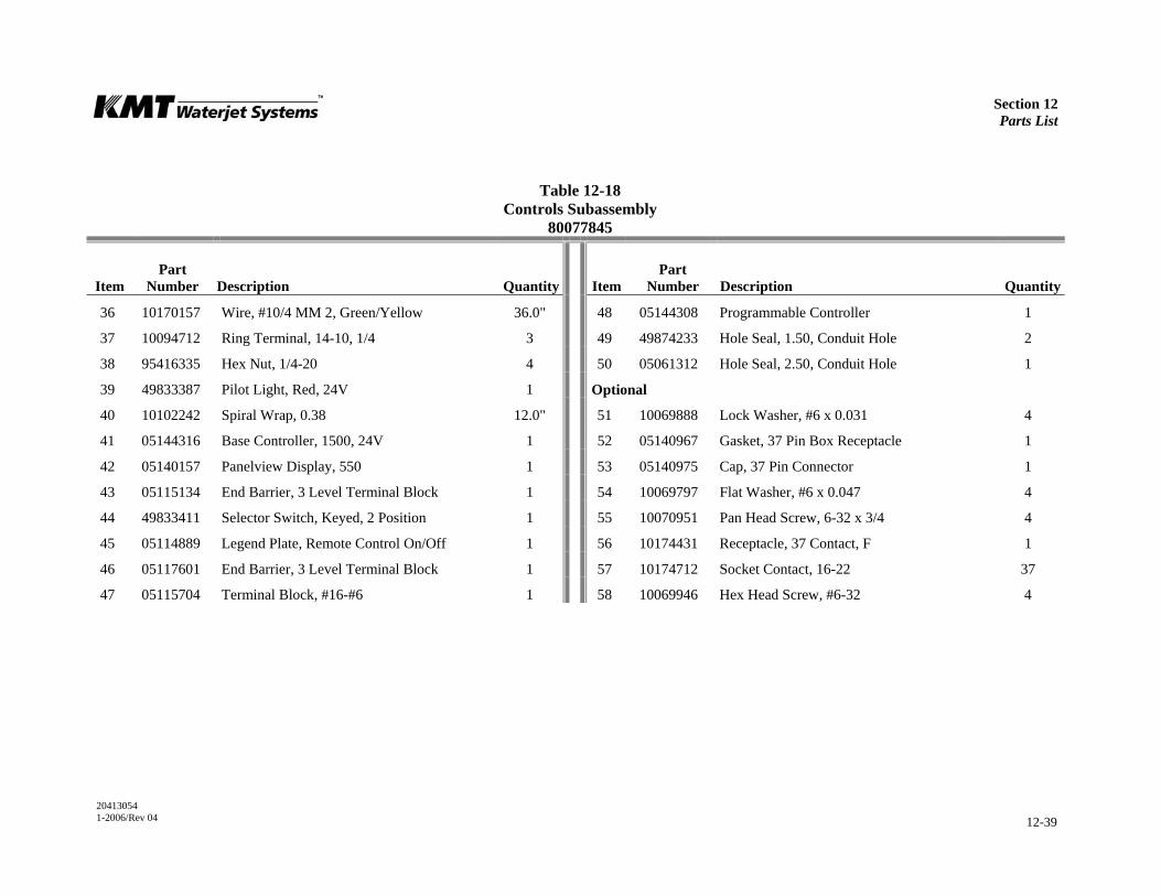
Section 12 Parts List
20413054 1-2006/Rev 04 12-39
Table 12-18 Controls Subassembly
80077845
Item
Part Number
Description
Quantity
Item
Part Number
Description
Quantity
36 10170157 Wire, #10/4 MM 2, Green/Yellow 36.0" 48 05144308 Programmable Controller 1
37 10094712 Ring Terminal, 14-10, 1/4 3 49 49874233 Hole Seal, 1.50, Conduit Hole 2
38 95416335 Hex Nut, 1/4-20 4 50 05061312 Hole Seal, 2.50, Conduit Hole 1
39 49833387 Pilot Light, Red, 24V 1 Optional
40 10102242 Spiral Wrap, 0.38 12.0" 51 10069888 Lock Washer, #6 x 0.031 4
41 05144316 Base Controller, 1500, 24V 1 52 05140967 Gasket, 37 Pin Box Receptacle 1
42 05140157 Panelview Display, 550 1 53 05140975 Cap, 37 Pin Connector 1
43 05115134 End Barrier, 3 Level Terminal Block 1 54 10069797 Flat Washer, #6 x 0.047 4
44 49833411 Selector Switch, Keyed, 2 Position 1 55 10070951 Pan Head Screw, 6-32 x 3/4 4
45 05114889 Legend Plate, Remote Control On/Off 1 56 10174431 Receptacle, 37 Contact, F 1
46 05117601 End Barrier, 3 Level Terminal Block 1 57 10174712 Socket Contact, 16-22 37
47 05115704 Terminal Block, #16-#6 1 58 10069946 Hex Head Screw, #6-32 4

Section 12 Parts List
20413054 1-2006/Rev 04 12-40
Figure 12-18: Controls Subassembly

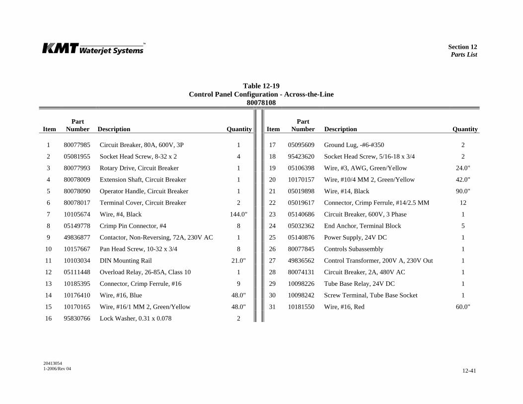
Section 12 Parts List
20413054 1-2006/Rev 04 12-41
Table 12-19 Control Panel Configuration - Across-the-Line
80078108
Item
Part Number
Description
Quantity
Item
Part Number
Description
Quantity
1 80077985 Circuit Breaker, 80A, 600V, 3P 1 17 05095609 Ground Lug, -#6-#350 2
2 05081955 Socket Head Screw, 8-32 x 2 4 18 95423620 Socket Head Screw, 5/16-18 x 3/4 2
3 80077993 Rotary Drive, Circuit Breaker 1 19 05106398 Wire, #3, AWG, Green/Yellow 24.0"
4 80078009 Extension Shaft, Circuit Breaker 1 20 10170157 Wire, #10/4 MM 2, Green/Yellow 42.0"
5 80078090 Operator Handle, Circuit Breaker 1 21 05019898 Wire, #14, Black 90.0"
6 80078017 Terminal Cover, Circuit Breaker 2 22 05019617 Connector, Crimp Ferrule, #14/2.5 MM 12
7 10105674 Wire, #4, Black 144.0" 23 05140686 Circuit Breaker, 600V, 3 Phase 1
8 05149778 Crimp Pin Connector, #4 8 24 05032362 End Anchor, Terminal Block 5
9 49836877 Contactor, Non-Reversing, 72A, 230V AC 1 25 05140876 Power Supply, 24V DC 1
10 10157667 Pan Head Screw, 10-32 x 3/4 8 26 80077845 Controls Subassembly 1
11 10103034 DIN Mounting Rail 21.0" 27 49836562 Control Transformer, 200V A, 230V Out 1
12 05111448 Overload Relay, 26-85A, Class 10 1 28 80074131 Circuit Breaker, 2A, 480V AC 1
13 10185395 Connector, Crimp Ferrule, #16 9 29 10098226 Tube Base Relay, 24V DC 1
14 10176410 Wire, #16, Blue 48.0" 30 10098242 Screw Terminal, Tube Base Socket 1
15 10170165 Wire, #16/1 MM 2, Green/Yellow 48.0" 31 10181550 Wire, #16, Red 60.0"
16 95830766 Lock Washer, 0.31 x 0.078 2
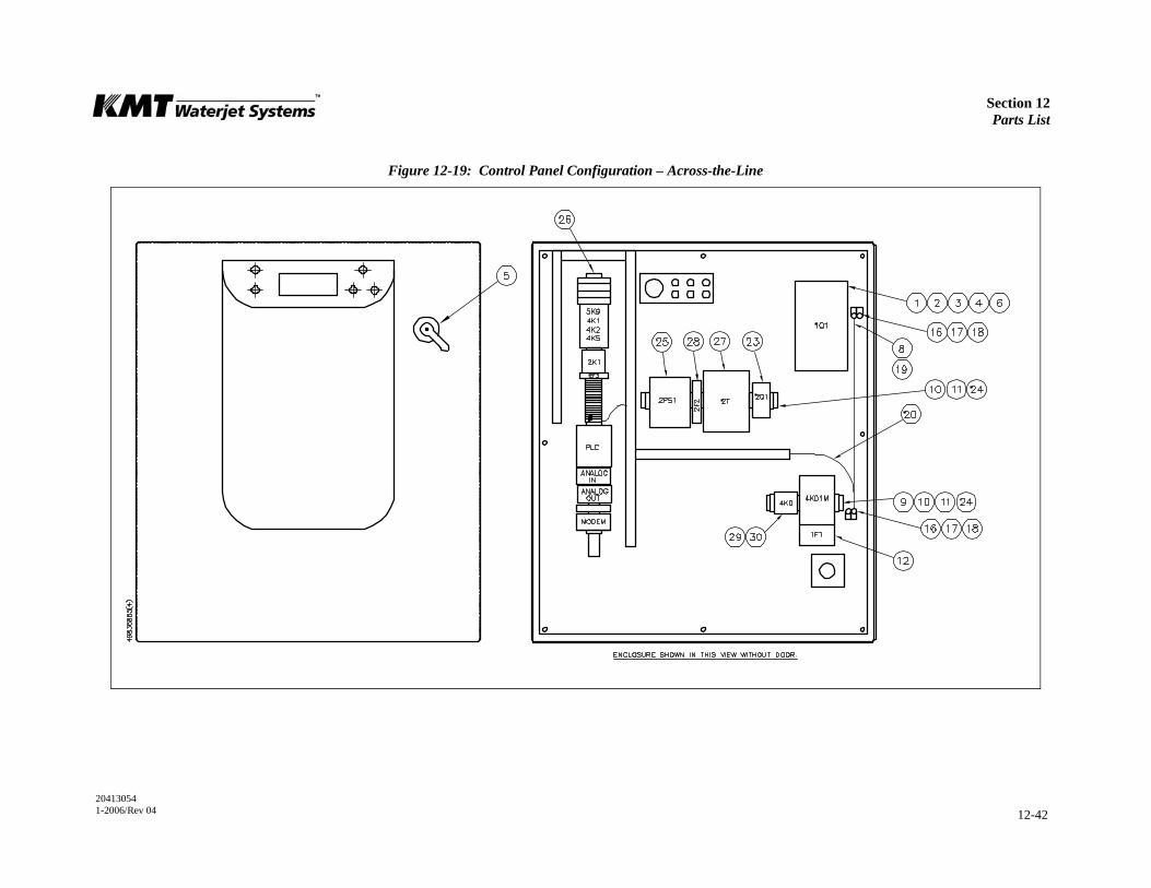
Section 12 Parts List
20413054 1-2006/Rev 04 12-42
Figure 12-19: Control Panel Configuration – Across-the-Line
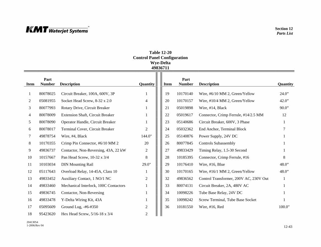
Section 12 Parts List
20413054 1-2006/Rev 04 12-43
Table 12-20 Control Panel Configuration
Wye-Delta 49836711
Item
Part Number
Description
Quantity
Item
Part Number
Description
Quantity
1 80078025 Circuit Breaker, 100A, 600V, 3P 1 19 10170140 Wire, #6/10 MM 2, Green/Yellow 24.0”
2 05081955 Socket Head Screw, 8-32 x 2.0 4 20 10170157 Wire, #10/4 MM 2, Green/Yellow 42.0”
3 80077993 Rotary Drive, Circuit Breaker 1 21 05019898 Wire, #14, Black 90.0”
4 80078009 Extension Shaft, Circuit Breaker 1 22 05019617 Connector, Crimp Ferrule, #14/2.5 MM 12
5 80078090 Operator Handle, Circuit Breaker 1 23 05140686 Circuit Breaker, 600V, 3 Phase 1
6 80078017 Terminal Cover, Circuit Breaker 2 24 05032362 End Anchor, Terminal Block 7
7 49878754 Wire, #4, Black 144.0" 25 05140876 Power Supply, 24V DC 1
8 10170355 Crimp Pin Connector, #6/10 MM 2 20 26 80077845 Controls Subassembly 1
9 49836737 Contactor, Non-Reversing, 43A, 22 kW 2 27 49833429 Timing Relay, 1.5-30 Second 1
10 10157667 Pan Head Screw, 10-32 x 3/4 8 28 10185395 Connector, Crimp Ferrule, #16 8
11 10103034 DIN Mounting Rail 29.0" 29 10176410 Wire, #16, Blue 48.0”
12 05117643 Overload Relay, 14-45A, Class 10 1 30 10170165 Wire, #16/1 MM 2, Green/Yellow 48.0”
13 49833452 Auxiliary Contact, 1 NO/1 NC 2 32 49836562 Control Transformer, 200V AC, 230V Out 1
14 49833460 Mechanical Interlock, 100C Contactors 1 33 80074131 Circuit Breaker, 2A, 480V AC 1
15 49836745 Contactor, Non-Reversing 1 34 10098226 Tube Base Relay, 24V DC 1
16 49833478 Y-Delta Wiring Kit, 43A 1 35 10098242 Screw Terminal, Tube Base Socket 1
17 05095609 Ground Lug, -#6-#350 2 36 10181550 Wire, #16, Red 100.0"
18 95423620 Hex Head Screw, 5/16-18 x 3/4 2
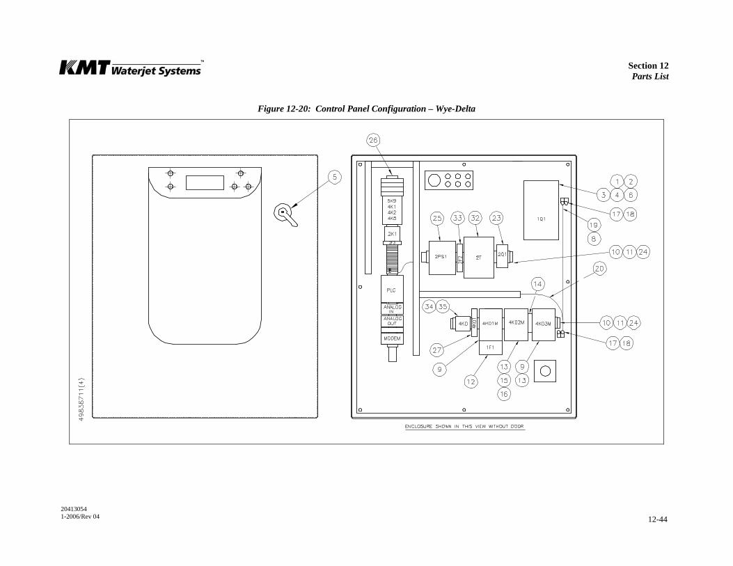
Section 12 Parts List
20413054 1-2006/Rev 04 12-44
Figure 12-20: Control Panel Configuration – Wye-Delta

Section 12 Parts List
20413054 1-2006/Rev 04 12-45
Table 12-21 Control Panel Configuration
230V, Wye-Delta 80073117
Item
Part Number
Description
Quantity
Item
Part Number
Description
Quantity
1 80077894 Circuit Breaker, 175A, 600V 1 19 10170140 Wire, #6/10 MM 2, Green/Yellow 24.0"
2 05081955 Socket Head Screw, 8-32 x 2 4 20 10170157 Wire, #10/4 MM 2, Green/Yellow 42.0"
5 80080377 Rotary Drive, Circuit Breaker 1 21 05019898 Wire, #14, Black 90.0"
6 80080385 Terminal Cover, Circuit Breaker 2 22 05019617 Connector, Crimp Ferrule, #14/2.5 MM 12
7 10121648 Wire, #4, Black 144.0" 23 05140686 Circuit Breaker, 600V, 3 Phase 1
8 05149778 Crimp Pin Connector, #4 8 24 05032362 End Anchor, Terminal Block 9
9 80080567 Contactor, Non-Reversing, 85A, 230 Coil 2 26 49836620 Controls Subassembly, 230V 1
10 10157667 Pan Head Screw, 10-32 x 3/4 12 27 49833429 Timing Relay, 1.5-30 Second 1
11 10103034 DIN Mounting Rail 15.0" 28 10185395 Connector, Crimp Ferrule, #16 8
12 05111448 Overload Relay, 26-85A, Class 10 1 29 10176410 Wire, #16, Blue 48.0”
13 49833452 Auxiliary Contact, 1 NO/1 NC 2 30 10170165 Wire, #16/1 MM 2, Green/Yellow 48.0”
14 49833460 Mechanical Interlock, 100C Contactors 1 32 05140876 Power Supply, 24V DC, 5A Out, 1 Phase In 1
15 49836984 Contactor, Non-Reversing, 60A, 230V AC 1 34 10098226 Tube Base Relay, 24V DC 1
16 49830367 Y-Delta Wiring Kit, 85A 1 35 10098242 Screw Terminal, Tube Base Socket 1
17 05095609 Ground Lug, -#6-#350 2 36 10181550 Wire, #16, Red 100.0"
18 95423620 Hex Head Screw, 5/16-18 x 3/4 2
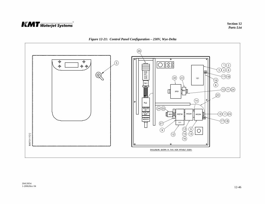
Section 12 Parts List
20413054 1-2006/Rev 04 12-46
Figure 12-21: Control Panel Configuration – 230V, Wye-Delta
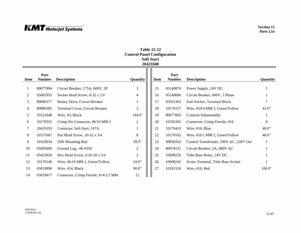
Section 12 Parts List
20413054 1-2006/Rev 04 12-47
Table 12-22 Control Panel Configuration
Soft Start 20421840
Item
Part Number
Description
Quantity
Item
Part Number
Description
Quantity
1 80077894 Circuit Breaker, 175A, 600V, 3P 1 15 05140876 Power Supply, 24V DC 1
2 05081955 Socket Head Screw, 8-32 x 2.0 4 16 05140686 Circuit Breaker, 600V, 3 Phase 1
3 80080377 Rotary Drive, Circuit Breaker 1 17 05032362 End Anchor, Terminal Block 7
4 80080385 Terminal Cover, Circuit Breaker 2 18 10170157 Wire, #10/4 MM 2, Green/Yellow 42.0”
5 10121648 Wire, #3, Black 144.0" 19 80077845 Controls Subassembly 1
6 10170355 Crimp Pin Connector, #6/10 MM 2 2 20 10185395 Connector, Crimp Ferrule, #16 8
7 20419193 Contactor, Soft Start, 147A 1 21 10176410 Wire, #16, Blue 48.0”
8 10157667 Pan Head Screw, 10-32 x 3/4 8 22 10170165 Wire, #16/1 MM 2, Green/Yellow 48.0”
9 10103034 DIN Mounting Rail 29.0" 23 49836562 Control Transformer, 200V AC, 230V Out 1
10 05095609 Ground Lug, -#6-#350 2 24 80074131 Circuit Breaker, 2A, 480V AC 1
11 95423620 Hex Head Screw, 5/16-18 x 3/4 2 25 10098226 Tube Base Relay, 24V DC 1
12 10170140 Wire, #6/10 MM 2, Green/Yellow 24.0” 26 10098242 Screw Terminal, Tube Base Socket 1
13 05019898 Wire, #14, Black 90.0” 27 10181550 Wire, #16, Red 100.0"
14 05019617 Connector, Crimp Ferrule, #14/2.5 MM 12
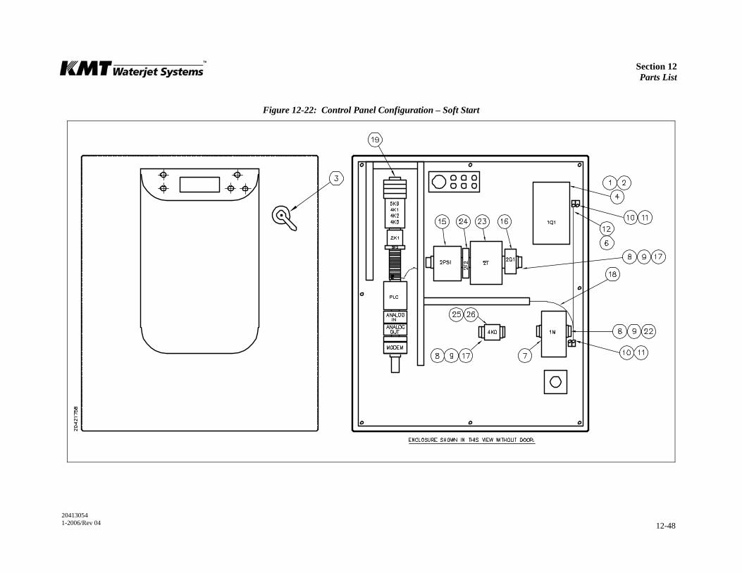
Section 12 Parts List
20413054 1-2006/Rev 04 12-48
Figure 12-22: Control Panel Configuration – Soft Start
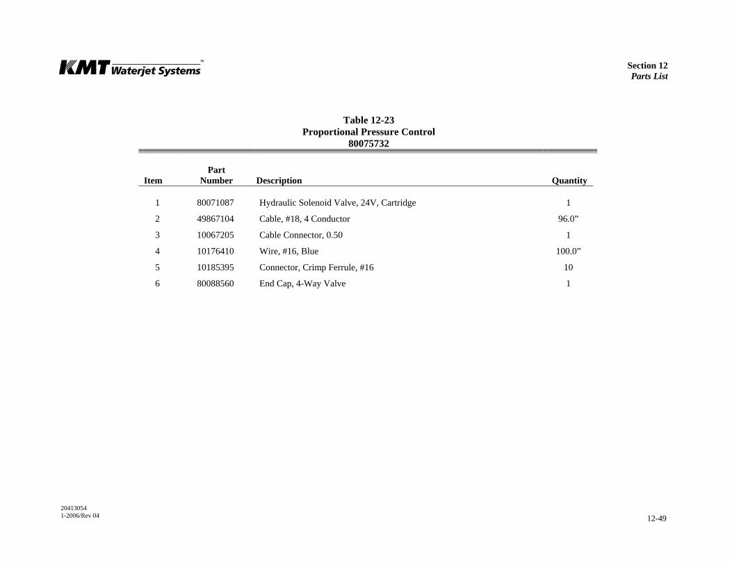
Section 12 Parts List
20413054 1-2006/Rev 04 12-49
Table 12-23 Proportional Pressure Control
80075732
Item
Part Number
Description
Quantity
1 80071087 Hydraulic Solenoid Valve, 24V, Cartridge 1
2 49867104 Cable, #18, 4 Conductor 96.0”
3 10067205 Cable Connector, 0.50 1
4 10176410 Wire, #16, Blue 100.0”
5 10185395 Connector, Crimp Ferrule, #16 10
6 80088560 End Cap, 4-Way Valve 1
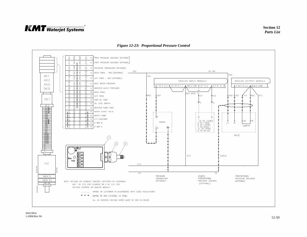
Section 12 Parts List
20413054 1-2006/Rev 04 12-50
Figure 12-23: Proportional Pressure Control
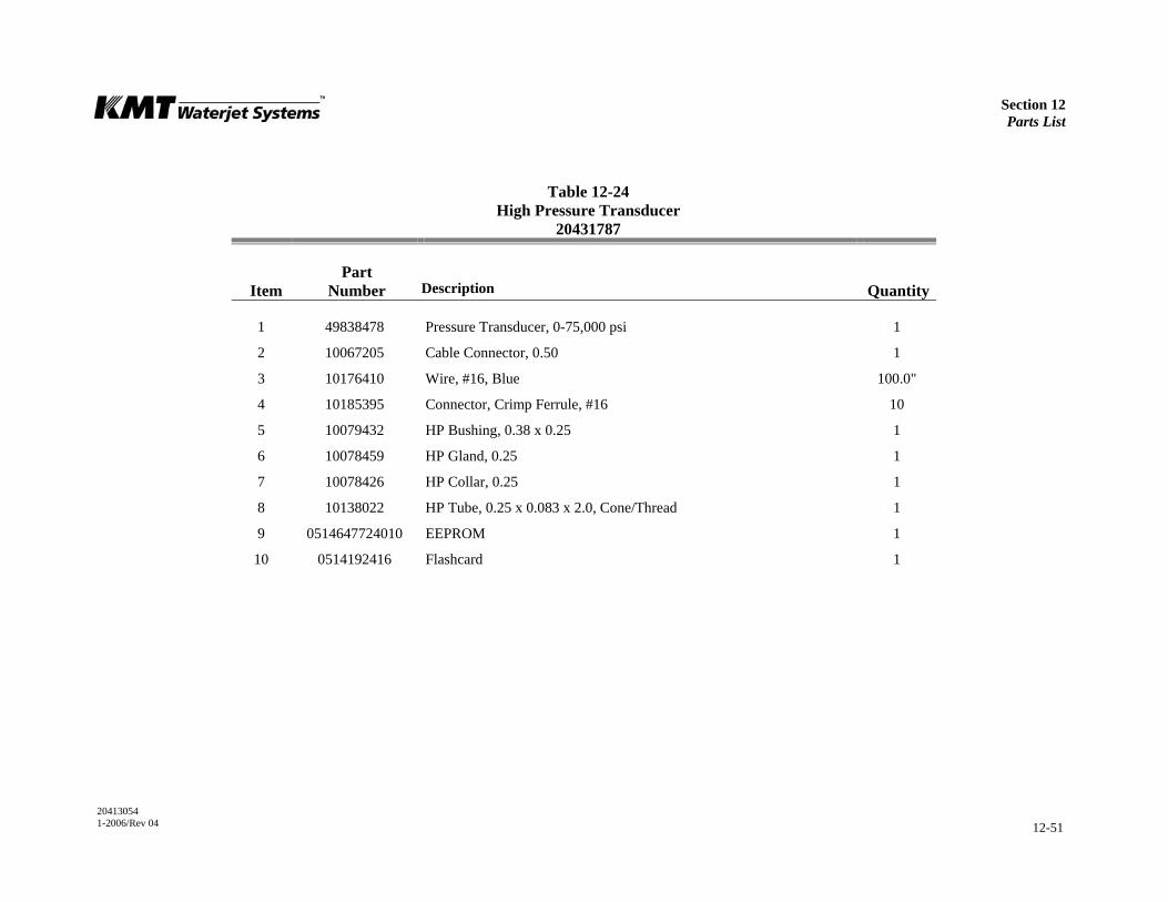
Section 12 Parts List
20413054 1-2006/Rev 04 12-51
Table 12-24 High Pressure Transducer
20431787
Item
Part Number
Description
Quantity
1 49838478 Pressure Transducer, 0-75,000 psi 1
2 10067205 Cable Connector, 0.50 1
3 10176410 Wire, #16, Blue 100.0"
4 10185395 Connector, Crimp Ferrule, #16 10
5 10079432 HP Bushing, 0.38 x 0.25 1
6 10078459 HP Gland, 0.25 1
7 10078426 HP Collar, 0.25 1
8 10138022 HP Tube, 0.25 x 0.083 x 2.0, Cone/Thread 1
9 0514647724010 EEPROM 1
10 0514192416 Flashcard 1

Section 12 Parts List
20413054 1-2006/Rev 04 12-52
Figure 12-24: High Pressure Transducer
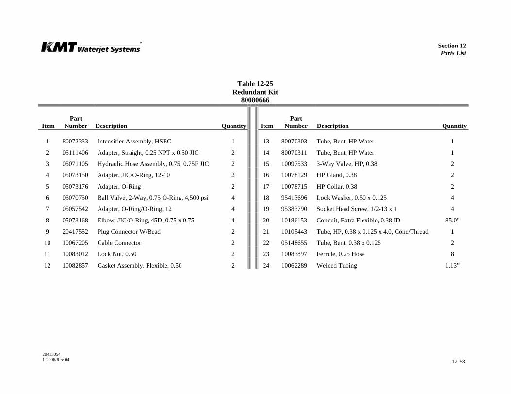
Section 12 Parts List
20413054 1-2006/Rev 04 12-53
Table 12-25 Redundant Kit
80080666
Item
Part Number
Description
Quantity
Item
Part Number
Description
Quantity
1 80072333 Intensifier Assembly, HSEC 1 13 80070303 Tube, Bent, HP Water 1
2 05111406 Adapter, Straight, 0.25 NPT x 0.50 JIC 2 14 80070311 Tube, Bent, HP Water 1
3 05071105 Hydraulic Hose Assembly, 0.75, 0.75F JIC 2 15 10097533 3-Way Valve, HP, 0.38 2
4 05073150 Adapter, JIC/O-Ring, 12-10 2 16 10078129 HP Gland, 0.38 2
5 05073176 Adapter, O-Ring 2 17 10078715 HP Collar, 0.38 2
6 05070750 Ball Valve, 2-Way, 0.75 O-Ring, 4,500 psi 4 18 95413696 Lock Washer, 0.50 x 0.125 4
7 05057542 Adapter, O-Ring/O-Ring, 12 4 19 95383790 Socket Head Screw, 1/2-13 x 1 4
8 05073168 Elbow, JIC/O-Ring, 45D, 0.75 x 0.75 4 20 10186153 Conduit, Extra Flexible, 0.38 ID 85.0"
9 20417552 Plug Connector W/Bead 2 21 10105443 Tube, HP, 0.38 x 0.125 x 4.0, Cone/Thread 1
10 10067205 Cable Connector 2 22 05148655 Tube, Bent, 0.38 x 0.125 2
11 10083012 Lock Nut, 0.50 2 23 10083897 Ferrule, 0.25 Hose 8
12 10082857 Gasket Assembly, Flexible, 0.50 2 24 10062289 Welded Tubing 1.13”
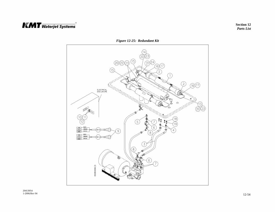
Section 12 Parts List
20413054 1-2006/Rev 04 12-54
Figure 12-25: Redundant Kit
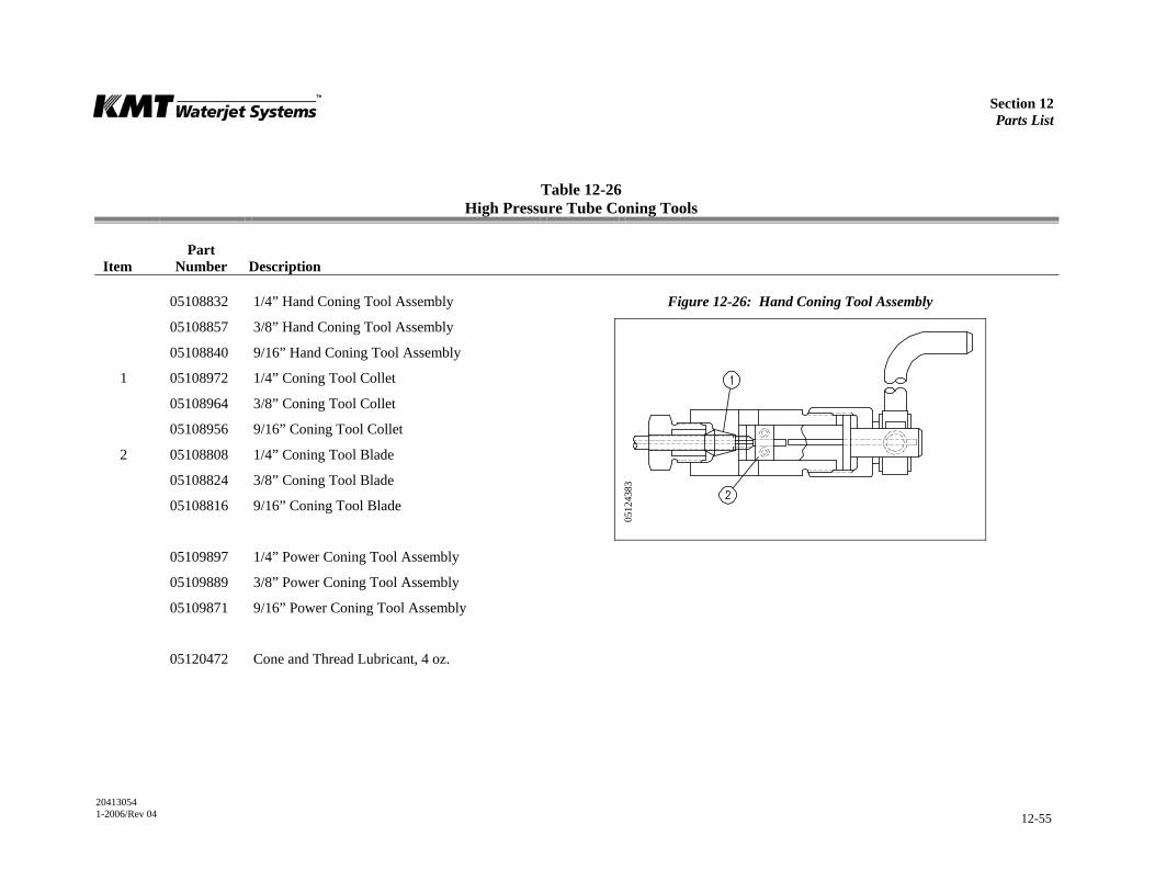
Section 12 Parts List
20413054 1-2006/Rev 04 12-55
Table 12-26 High Pressure Tube Coning Tools
Item
Part Number
Description
05108832 1/4” Hand Coning Tool Assembly Figure 12-26: Hand Coning Tool Assembly
05108857 3/8” Hand Coning Tool Assembly
05108840 9/16” Hand Coning Tool Assembly
1 05108972 1/4” Coning Tool Collet
05108964 3/8” Coning Tool Collet
05108956 9/16” Coning Tool Collet
2 05108808 1/4” Coning Tool Blade
05108824 3/8” Coning Tool Blade
05108816 9/16” Coning Tool Blade
05109897 1/4” Power Coning Tool Assembly
05109889 3/8” Power Coning Tool Assembly
05109871 9/16” Power Coning Tool Assembly
05120472 Cone and Thread Lubricant, 4 oz.
0512
4383
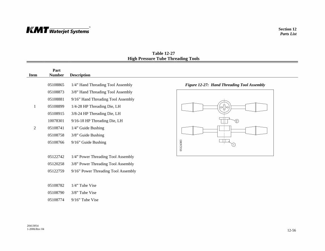
Section 12 Parts List
20413054 1-2006/Rev 04 12-56
Table 12-27 High Pressure Tube Threading Tools
Item
Part Number
Description
05108865 1/4” Hand Threading Tool Assembly Figure 12-27: Hand Threading Tool Assembly
05108873 3/8” Hand Threading Tool Assembly
05108881 9/16” Hand Threading Tool Assembly
1 05108899 1/4-28 HP Threading Die, LH
05108915 3/8-24 HP Threading Die, LH
10078301 9/16-18 HP Threading Die, LH
2 05108741 1/4” Guide Bushing
05108758 3/8” Guide Bushing
05108766 9/16” Guide Bushing
05122742 1/4” Power Threading Tool Assembly
05120258 3/8” Power Threading Tool Assembly
05122759 9/16” Power Threading Tool Assembly
05108782 1/4” Tube Vise
05108790 3/8” Tube Vise
05108774 9/16” Tube Vise
0512
4383
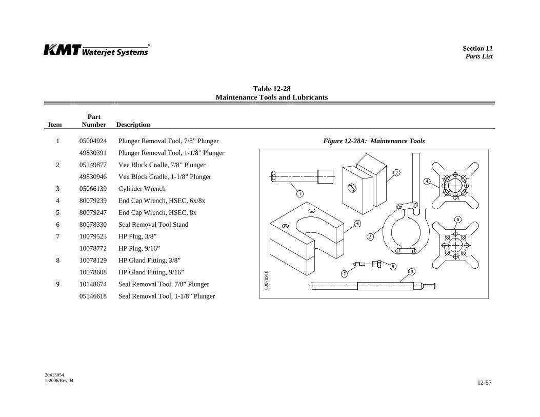
Section 12 Parts List
20413054 1-2006/Rev 04 12-57
Table 12-28 Maintenance Tools and Lubricants
Item
Part Number
Description
1 05004924 Plunger Removal Tool, 7/8” Plunger Figure 12-28A: Maintenance Tools
49830391 Plunger Removal Tool, 1-1/8” Plunger
2 05149877 Vee Block Cradle, 7/8” Plunger
49830946 Vee Block Cradle, 1-1/8” Plunger
3 05066139 Cylinder Wrench
4 80079239 End Cap Wrench, HSEC, 6x/8x
5 80079247 End Cap Wrench, HSEC, 8x
6 80078330 Seal Removal Tool Stand
7 10079523 HP Plug, 3/8”
10078772 HP Plug, 9/16”
8 10078129 HP Gland Fitting, 3/8”
10078608 HP Gland Fitting, 9/16”
9 10148674 Seal Removal Tool, 7/8” Plunger
05146618 Seal Removal Tool, 1-1/8” Plunger
8007
8918
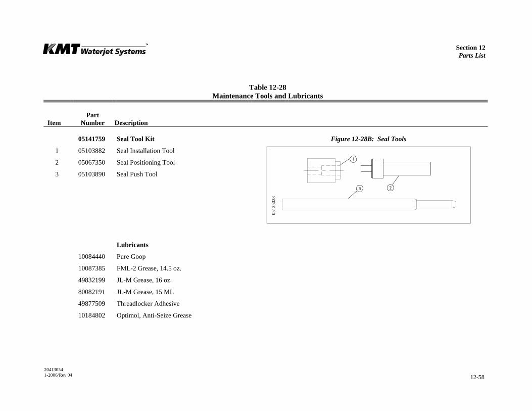
Section 12 Parts List
20413054 1-2006/Rev 04 12-58
Table 12-28 Maintenance Tools and Lubricants
Item
Part Number
Description
05141759 Seal Tool Kit Figure 12-28B: Seal Tools
1 05103882 Seal Installation Tool
2 05067350 Seal Positioning Tool
3 05103890 Seal Push Tool
Lubricants
10084440 Pure Goop
10087385 FML-2 Grease, 14.5 oz.
49832199 JL-M Grease, 16 oz.
80082191 JL-M Grease, 15 ML
49877509 Threadlocker Adhesive
10184802 Optimol, Anti-Seize Grease
0513
5033
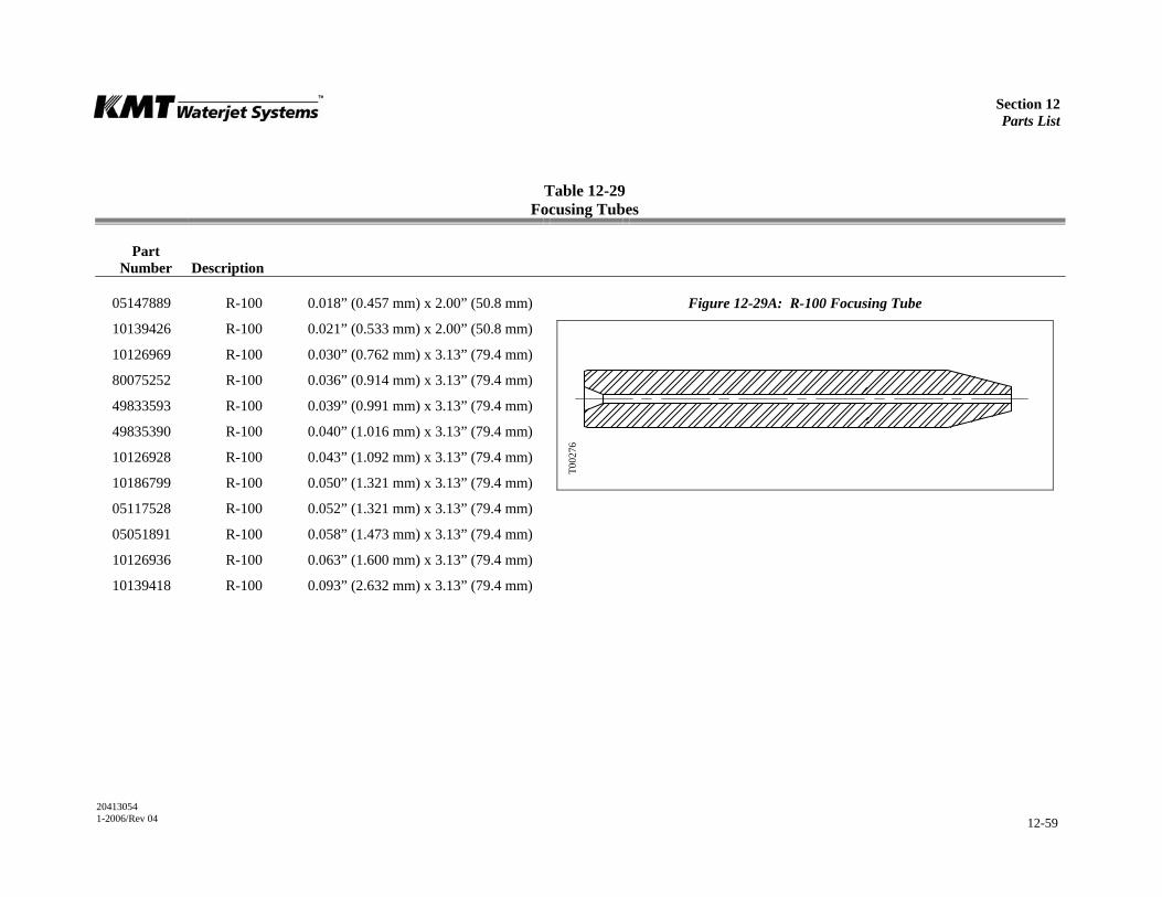
Section 12 Parts List
20413054 1-2006/Rev 04 12-59
Table 12-29 Focusing Tubes
Part Number
Description
05147889 R-100 0.018” (0.457 mm) x 2.00” (50.8 mm) Figure 12-29A: R-100 Focusing Tube
10139426 R-100 0.021” (0.533 mm) x 2.00” (50.8 mm)
10126969 R-100 0.030” (0.762 mm) x 3.13” (79.4 mm)
80075252 R-100 0.036” (0.914 mm) x 3.13” (79.4 mm)
49833593 R-100 0.039” (0.991 mm) x 3.13” (79.4 mm)
49835390 R-100 0.040” (1.016 mm) x 3.13” (79.4 mm)
10126928 R-100 0.043” (1.092 mm) x 3.13” (79.4 mm)
10186799 R-100 0.050” (1.321 mm) x 3.13” (79.4 mm)
05117528 R-100 0.052” (1.321 mm) x 3.13” (79.4 mm)
05051891 R-100 0.058” (1.473 mm) x 3.13” (79.4 mm)
10126936 R-100 0.063” (1.600 mm) x 3.13” (79.4 mm)
10139418 R-100 0.093” (2.632 mm) x 3.13” (79.4 mm)
T002
76
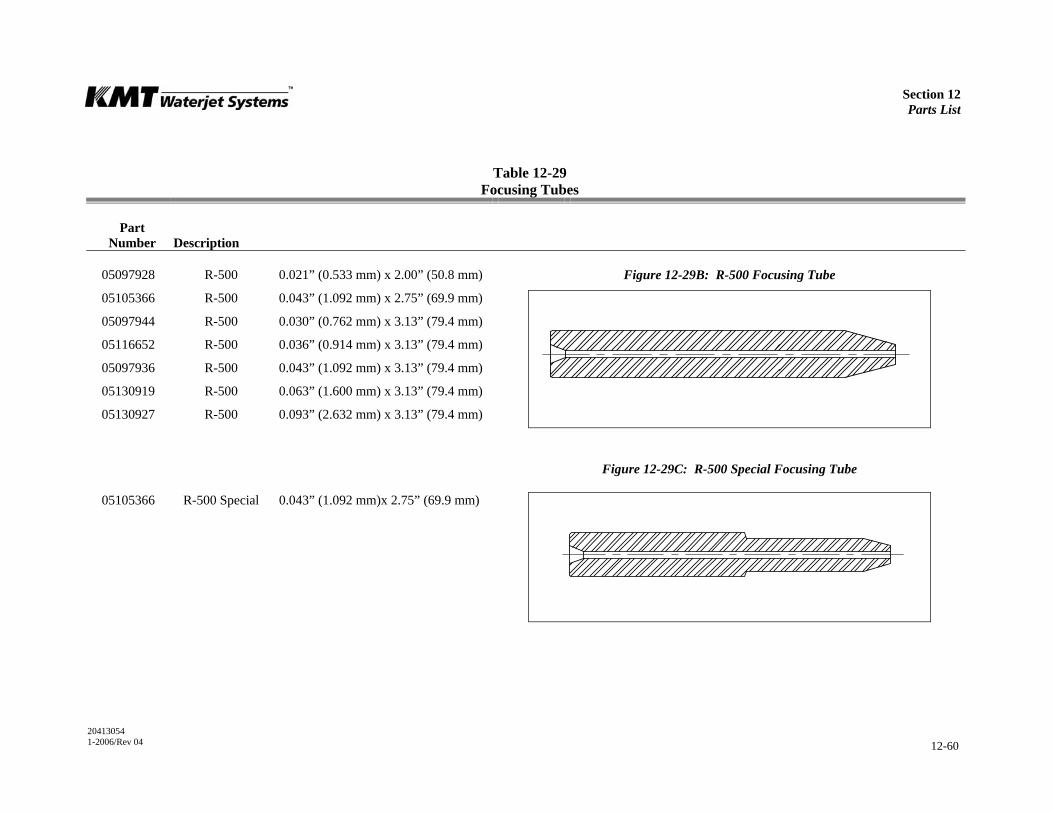
Section 12 Parts List
20413054 1-2006/Rev 04 12-60
Table 12-29 Focusing Tubes
Part Number
Description
05097928 R-500 0.021” (0.533 mm) x 2.00” (50.8 mm) Figure 12-29B: R-500 Focusing Tube
05105366 R-500 0.043” (1.092 mm) x 2.75” (69.9 mm)
05097944 R-500 0.030” (0.762 mm) x 3.13” (79.4 mm)
05116652 R-500 0.036” (0.914 mm) x 3.13” (79.4 mm)
05097936 R-500 0.043” (1.092 mm) x 3.13” (79.4 mm)
05130919 R-500 0.063” (1.600 mm) x 3.13” (79.4 mm)
05130927 R-500 0.093” (2.632 mm) x 3.13” (79.4 mm)
Figure 12-29C: R-500 Special Focusing Tube
05105366 R-500 Special 0.043” (1.092 mm)x 2.75” (69.9 mm)
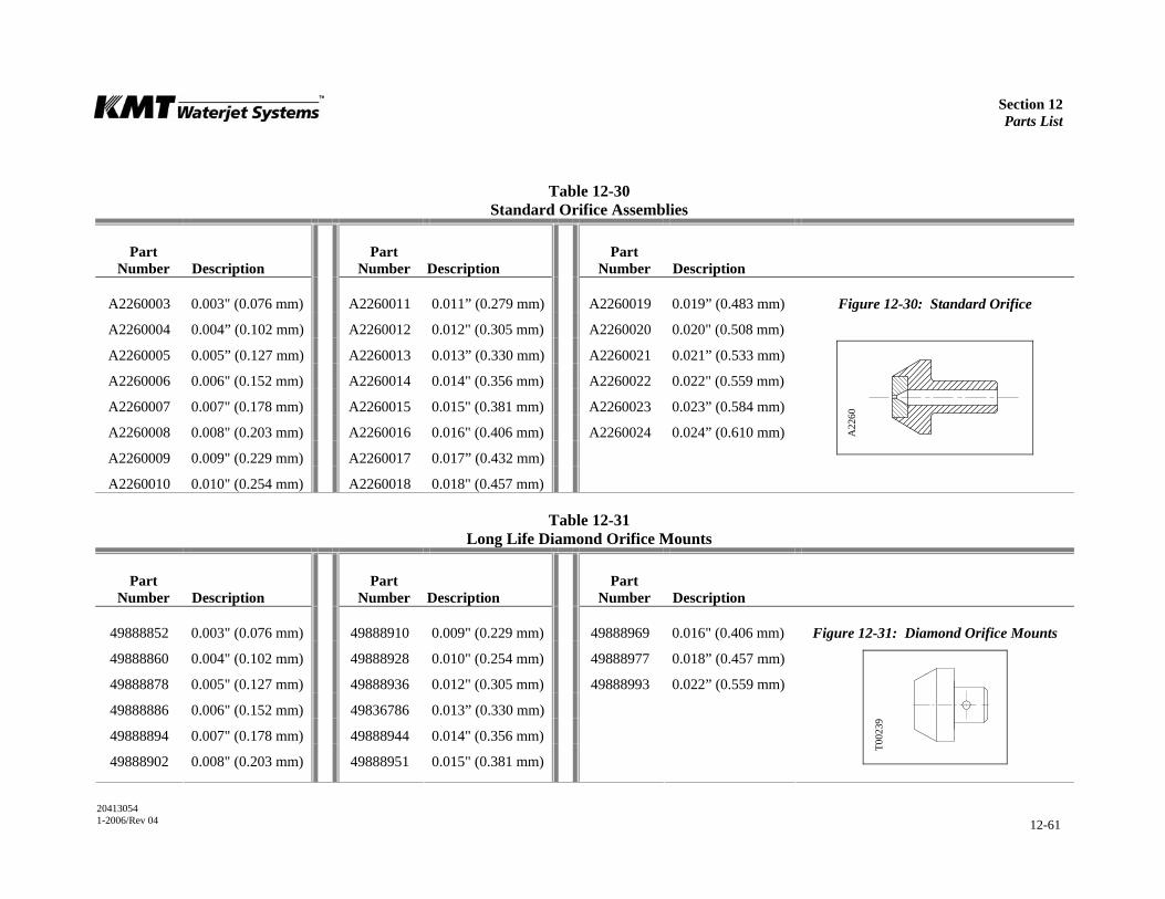
Section 12 Parts List
20413054 1-2006/Rev 04 12-61
Table 12-30 Standard Orifice Assemblies
Part Number
Description
Part Number
Description
Part Number
Description
A2260003 0.003" (0.076 mm) A2260011 0.011” (0.279 mm) A2260019 0.019” (0.483 mm) Figure 12-30: Standard Orifice
A2260004 0.004” (0.102 mm) A2260012 0.012" (0.305 mm) A2260020 0.020" (0.508 mm)
A2260005 0.005” (0.127 mm) A2260013 0.013” (0.330 mm) A2260021 0.021” (0.533 mm)
A2260006 0.006" (0.152 mm) A2260014 0.014" (0.356 mm) A2260022 0.022" (0.559 mm)
A2260007 0.007" (0.178 mm) A2260015 0.015" (0.381 mm) A2260023 0.023” (0.584 mm)
A2260008 0.008" (0.203 mm) A2260016 0.016" (0.406 mm) A2260024 0.024” (0.610 mm)
A2260009 0.009" (0.229 mm) A2260017 0.017” (0.432 mm)
A2260010 0.010" (0.254 mm) A2260018 0.018" (0.457 mm)
Table 12-31 Long Life Diamond Orifice Mounts
Part Number
Description
Part Number
Description
Part Number
Description
49888852 0.003" (0.076 mm) 49888910 0.009" (0.229 mm) 49888969 0.016" (0.406 mm) Figure 12-31: Diamond Orifice Mounts
49888860 0.004" (0.102 mm) 49888928 0.010" (0.254 mm) 49888977 0.018” (0.457 mm)
49888878 0.005" (0.127 mm) 49888936 0.012" (0.305 mm) 49888993 0.022” (0.559 mm)
49888886 0.006" (0.152 mm) 49836786 0.013” (0.330 mm)
49888894 0.007" (0.178 mm) 49888944 0.014" (0.356 mm)
49888902 0.008" (0.203 mm) 49888951 0.015" (0.381 mm)
A22
60
T002
39
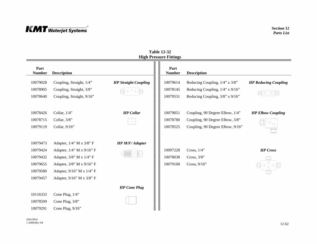
Section 12 Parts List
20413054 1-2006/Rev 04 12-62
Table 12-32 High Pressure Fittings
Part Number
Description
Part Number
Description
10079028 Coupling, Straight, 1/4” HP Straight Coupling 10079614 Reducing Coupling, 1/4” x 3/8” HP Reducing Coupling
10078905 Coupling, Straight, 3/8” 10078145 Reducing Coupling, 1/4” x 9/16”
10078640 Coupling, Straight, 9/16” 10079531 Reducing Coupling, 3/8” x 9/16”
10078426 Collar, 1/4” HP Collar 10079051 Coupling, 90 Degree Elbow, 1/4” HP Elbow Coupling
10078715 Collar, 3/8” 10078780 Coupling, 90 Degree Elbow, 3/8”
10079119 Collar, 9/16” 10078525 Coupling, 90 Degree Elbow, 9/16”
10079473 Adapter, 1/4” M x 3/8” F HP M/F/ Adapter
10079424 Adapter, 1/4” M x 9/16” F 10097228 Cross, 1/4” HP Cross
10079432 Adapter, 3/8” M x 1/4” F 10078038 Cross, 3/8”
10079655 Adapter, 3/8” M x 9/16” F 10079168 Cross, 9/16”
10079580 Adapter, 9/16” M x 1/4” F
10079457 Adapter, 9/16” M x 3/8” F
HP Cone Plug
10116333 Cone Plug, 1/4”
10078509 Cone Plug, 3/8”
10079291 Cone Plug, 9/16”
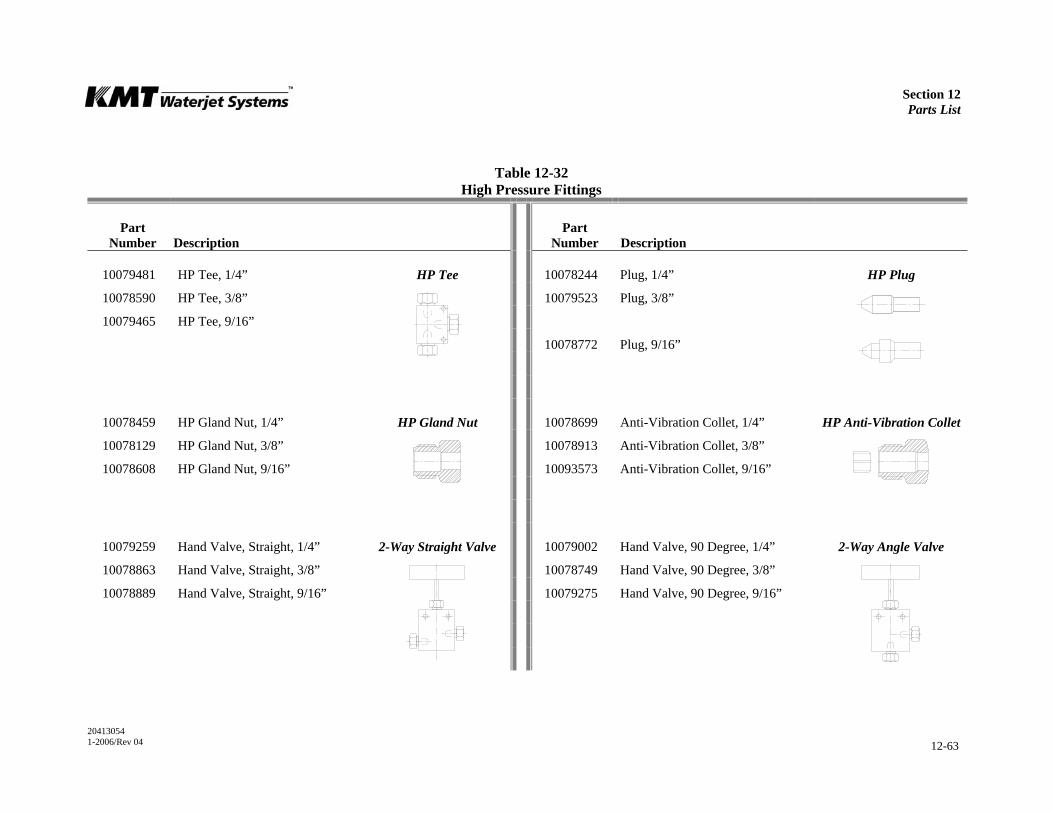
Section 12 Parts List
20413054 1-2006/Rev 04 12-63
Table 12-32 High Pressure Fittings
Part Number
Description
Part Number
Description
10079481 HP Tee, 1/4” HP Tee 10078244 Plug, 1/4” HP Plug
10078590 HP Tee, 3/8” 10079523 Plug, 3/8”
10079465 HP Tee, 9/16”
10078772 Plug, 9/16”
10078459 HP Gland Nut, 1/4” HP Gland Nut 10078699 Anti-Vibration Collet, 1/4” HP Anti-Vibration Collet
10078129 HP Gland Nut, 3/8” 10078913 Anti-Vibration Collet, 3/8”
10078608 HP Gland Nut, 9/16” 10093573 Anti-Vibration Collet, 9/16”
10079259 Hand Valve, Straight, 1/4” 2-Way Straight Valve 10079002 Hand Valve, 90 Degree, 1/4” 2-Way Angle Valve
10078863 Hand Valve, Straight, 3/8” 10078749 Hand Valve, 90 Degree, 3/8”
10078889 Hand Valve, Straight, 9/16” 10079275 Hand Valve, 90 Degree, 9/16”
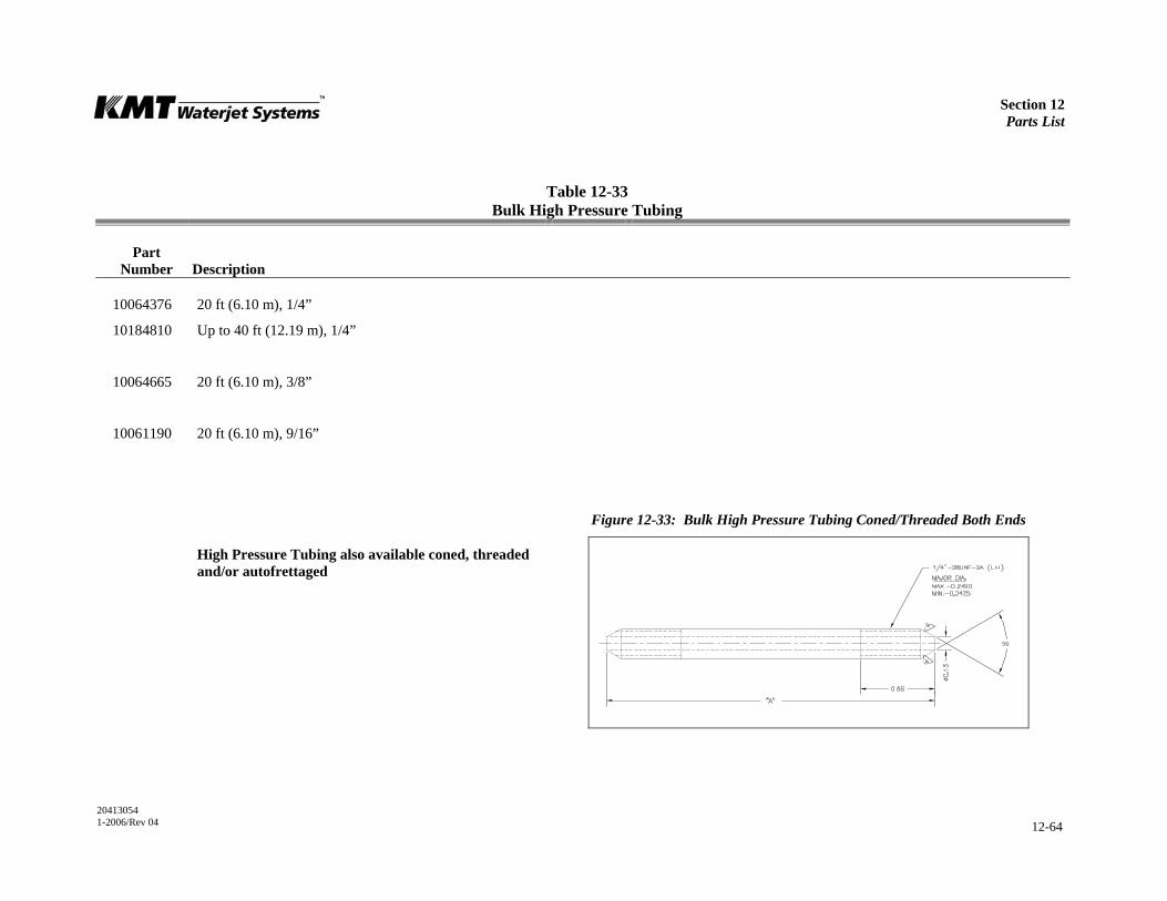
Section 12 Parts List
20413054 1-2006/Rev 04 12-64
Table 12-33 Bulk High Pressure Tubing
Part Number
Description
10064376 20 ft (6.10 m), 1/4”
10184810 Up to 40 ft (12.19 m), 1/4”
10064665 20 ft (6.10 m), 3/8”
10061190 20 ft (6.10 m), 9/16”
Figure 12-33: Bulk High Pressure Tubing Coned/Threaded Both Ends
High Pressure Tubing also available coned, threaded and/or autofrettaged
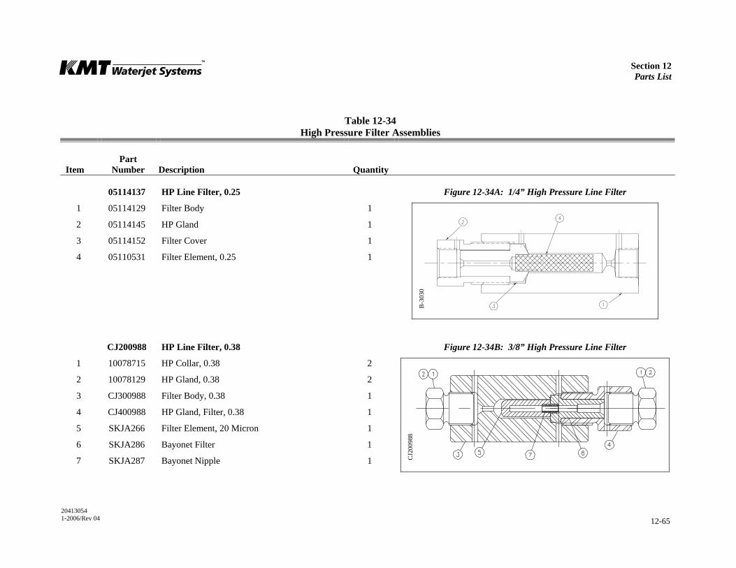
Section 12 Parts List
20413054 1-2006/Rev 04 12-65
Table 12-34 High Pressure Filter Assemblies
Item
Part Number
Description
Quantity
05114137 HP Line Filter, 0.25 Figure 12-34A: 1/4” High Pressure Line Filter
1 05114129 Filter Body 1
2 05114145 HP Gland 1
3 05114152 Filter Cover 1
4 05110531 Filter Element, 0.25 1
CJ200988 HP Line Filter, 0.38 Figure 12-34B: 3/8” High Pressure Line Filter
1 10078715 HP Collar, 0.38 2
2 10078129 HP Gland, 0.38 2
3 CJ300988 Filter Body, 0.38 1
4 CJ400988 HP Gland, Filter, 0.38 1
5 SKJA266 Filter Element, 20 Micron 1
6 SKJA286 Bayonet Filter 1
7 SKJA287 Bayonet Nipple 1
B-3
030
CJ2
0098
8

Section 12 Parts List
20413054 1-2006/Rev 04 12-66
Table 12-34 High Pressure Filter Assemblies
Item
Part Number
Description
Quantity
BF103473 HP Line Filter, 0.56 Figure 12-34C: 9/16” High Pressure Line Filter
1 AF413972 HP Gland, 0.562 1
2 AF303473 Seal Head, 0.56, Outlet 1
3 AF503473 Filter Element, 20 Micron 1
4 BF203473 Filter Body, 0.5625 Connection 1
5 AF913972 HP Gland, 0.656 1
6 10074599 O-Ring, 3/8 x 1/2 x 1/16 1
7 AF403473 Seal Head, 0.56, Inlet 1
BF1
0347
3
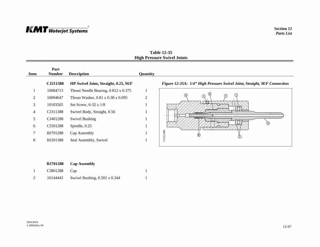
Section 12 Parts List
20413054 1-2006/Rev 04 12-67
Table 12-35 High Pressure Swivel Joints
Item
Part Number
Description
Quantity
CJ211388 HP Swivel Joint, Straight, 0.25, M/F Figure 12-35A: 1/4” High Pressure Swivel Joint, Straight, M/F Connection
1 10084713 Thrust Needle Bearing, 0.812 x 0.375 1
2 10094647 Thrust Washer, 0.81 x 0.38 x 0.095 2
3 10103505 Set Screw, 6-32 x 1/8 1
4 CJ311388 Swivel Body, Straight, 0.56 1
5 CJ401288 Swivel Bushing 1
6 CJ501288 Spindle, 0.25 1
7 BJ701288 Cap Assembly 1
8 BJ201388 Seal Assembly, Swivel 1
BJ701288 Cap Assembly
1 CJ801288 Cap 1
2 10144442 Swivel Bushing, 0.502 x 0.344 1
CJ2
1138
8

Section 12 Parts List
20413054 1-2006/Rev 04 12-68
Table 12-35 High Pressure Swivel Joints
Item
Part Number
Description
Quantity
CJ211388 HP Swivel Joint, Straight, 0.25, M/F Figure 12-35B: 1/4” High Pressure Swivel Joint, Straight, M/F Connection
1 10084713 Thrust Needle Bearing, 0.812 x 0.375 1
2 10094647 Thrust Washer, 0.81 x 0.38 x 0.095 2
3 10103505 Set Screw, 6-32 x 1/8 1
4 CJ311388 Swivel Body, Straight, 0.56 1
5 CJ401288 Swivel Bushing, 90D 1
6 CJ501288 Spindle, 0.25 1
7 BJ701288 Cap Assembly 1
8 BJ201388 Seal Assembly, Swivel 1
CJ2
1138
8
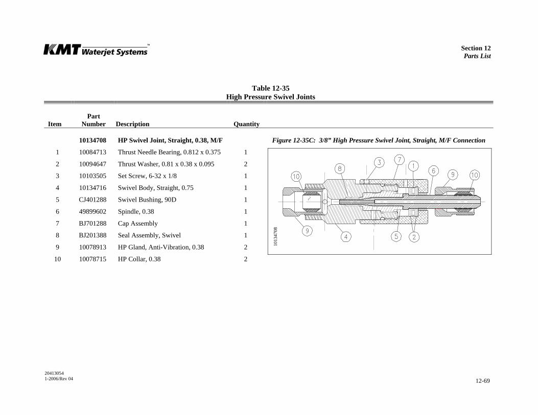
Section 12 Parts List
20413054 1-2006/Rev 04 12-69
Table 12-35 High Pressure Swivel Joints
Item
Part Number
Description
Quantity
10134708 HP Swivel Joint, Straight, 0.38, M/F Figure 12-35C: 3/8” High Pressure Swivel Joint, Straight, M/F Connection
1 10084713 Thrust Needle Bearing, 0.812 x 0.375 1
2 10094647 Thrust Washer, 0.81 x 0.38 x 0.095 2
3 10103505 Set Screw, 6-32 x 1/8 1
4 10134716 Swivel Body, Straight, 0.75 1
5 CJ401288 Swivel Bushing, 90D 1
6 49899602 Spindle, 0.38 1
7 BJ701288 Cap Assembly 1
8 BJ201388 Seal Assembly, Swivel 1
9 10078913 HP Gland, Anti-Vibration, 0.38 2
10 10078715 HP Collar, 0.38 2
1013
4708
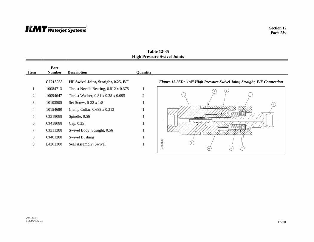
Section 12 Parts List
20413054 1-2006/Rev 04 12-70
Table 12-35 High Pressure Swivel Joints
Item
Part Number
Description
Quantity
CJ218088 HP Swivel Joint, Straight, 0.25, F/F Figure 12-35D: 1/4” High Pressure Swivel Joint, Straight, F/F Connection
1 10084713 Thrust Needle Bearing, 0.812 x 0.375 1
2 10094647 Thrust Washer, 0.81 x 0.38 x 0.095 2
3 10103505 Set Screw, 6-32 x 1/8 1
4 10154680 Clamp Collar, 0.688 x 0.313 1
5 CJ318088 Spindle, 0.56 1
6 CJ418088 Cap, 0.25 1
7 CJ311388 Swivel Body, Straight, 0.56 1
8 CJ401288 Swivel Bushing 1
9 BJ201388 Seal Assembly, Swivel 1
CJ2
1808
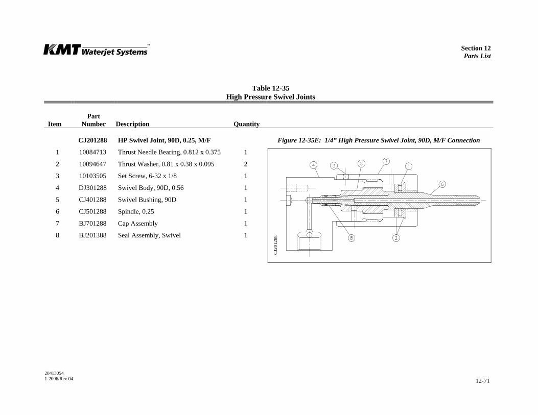
Section 12 Parts List
20413054 1-2006/Rev 04 12-71
Table 12-35 High Pressure Swivel Joints
Item
Part Number
Description
Quantity
CJ201288 HP Swivel Joint, 90D, 0.25, M/F Figure 12-35E: 1/4” High Pressure Swivel Joint, 90D, M/F Connection
1 10084713 Thrust Needle Bearing, 0.812 x 0.375 1
2 10094647 Thrust Washer, 0.81 x 0.38 x 0.095 2
3 10103505 Set Screw, 6-32 x 1/8 1
4 DJ301288 Swivel Body, 90D, 0.56 1
5 CJ401288 Swivel Bushing, 90D 1
6 CJ501288 Spindle, 0.25 1
7 BJ701288 Cap Assembly 1
8 BJ201388 Seal Assembly, Swivel 1
CJ2
0128
8

Section 12 Parts List
20413054 1-2006/Rev 04 12-72
Table 12-35 High Pressure Swivel Joints
Item
Part Number
Description
Quantity
10134682 HP Swivel Joint, 90D, 0.38, M/F Figure 12-35F: 3/8” High Pressure Swivel Joint, 90D, M/F Connection
1 10084713 Thrust Needle Bearing, 0.812 x 0.375 1
2 10094647 Thrust Washer, 0.81 x 0.38 x 0.095 2
3 10103505 Set Screw, 6-32 x 1/8 1
4 10134690 Swivel Body, 90D, 0.75 1
5 CJ401288 Swivel Bushing, 90D 1
6 49899602 Spindle, 0.38 1
7 BJ701288 Cap Assembly 1
8 BJ201388 Seal Assembly, Swivel 1
9 10078913 HP Gland, Anti-Vibration, 0.38 2
10 10078715 HP Collar, 0.38 2
1013
468

Section 12 Parts List
20413054 1-2006/Rev 04 12-73
Table 12-35 High Pressure Swivel Joints
Item
Part Number
Description
Quantity
10134682 HP Swivel Joint, 90D, 0.25, F/F Figure 12-35G: 1/4” High Pressure Swivel Joint, 90D, F/F Connection
1 10084713 Thrust Needle Bearing, 0.812 x 0.375 1
2 10094647 Thrust Washer, 0.81 x 0.38 x 0.095 2
3 10103505 Set Screw, 6-32 x 1/8 1
4 10154680 Clamp Collar, 0.688 x 0.313 1
5 CJ318088 Spindle, 0.56 1
6 CJ418088 Cap, 0.25 1
7 DJ301288 Swivel Body, 90D, 0.56 1
8 CJ401288 Swivel Bushing, 90D 1
9 BJ201388 Seal Assembly, Swivel 1
CJ2
1818
8
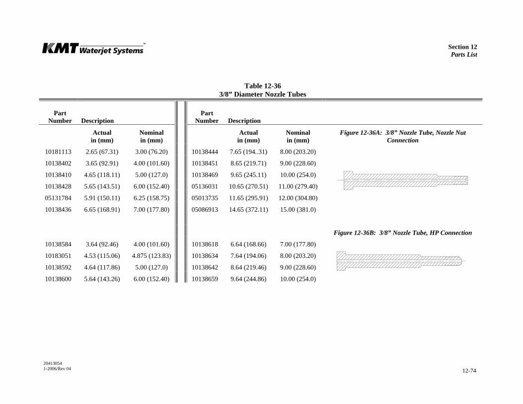
Section 12 Parts List
20413054 1-2006/Rev 04 12-74
Table 12-36 3/8” Diameter Nozzle Tubes
Part Number
Description
Part Number
Description
Actual in (mm)
Nominal in (mm)
Actual in (mm)
Nominal in (mm)
Figure 12-36A: 3/8” Nozzle Tube, Nozzle Nut Connection
10181113 2.65 (67.31) 3.00 (76.20) 10138444 7.65 (194..31) 8.00 (203.20)
10138402 3.65 (92.91) 4.00 (101.60) 10138451 8.65 (219.71) 9.00 (228.60)
10138410 4.65 (118.11) 5.00 (127.0) 10138469 9.65 (245.11) 10.00 (254.0)
10138428 5.65 (143.51) 6.00 (152.40) 05136031 10.65 (270.51) 11.00 (279.40)
05131784 5.91 (150.11) 6.25 (158.75) 05013735 11.65 (295.91) 12.00 (304.80)
10138436 6.65 (168.91) 7.00 (177.80) 05086913 14.65 (372.11) 15.00 (381.0)
Figure 12-36B: 3/8” Nozzle Tube, HP Connection
10138584 3.64 (92.46) 4.00 (101.60) 10138618 6.64 (168.66) 7.00 (177.80)
10183051 4.53 (115.06) 4.875 (123.83) 10138634 7.64 (194.06) 8.00 (203.20)
10138592 4.64 (117.86) 5.00 (127.0) 10138642 8.64 (219.46) 9.00 (228.60)
10138600 5.64 (143.26) 6.00 (152.40) 10138659 9.64 (244.86) 10.00 (254.0)
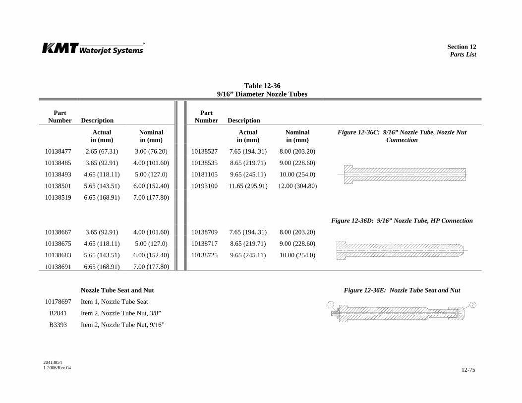
Section 12 Parts List
20413054 1-2006/Rev 04 12-75
Table 12-36 9/16” Diameter Nozzle Tubes
Part Number
Description
Part Number
Description
Actual in (mm)
Nominal in (mm)
Actual in (mm)
Nominal in (mm)
Figure 12-36C: 9/16” Nozzle Tube, Nozzle Nut Connection
10138477 2.65 (67.31) 3.00 (76.20) 10138527 7.65 (194..31) 8.00 (203.20)
10138485 3.65 (92.91) 4.00 (101.60) 10138535 8.65 (219.71) 9.00 (228.60)
10138493 4.65 (118.11) 5.00 (127.0) 10181105 9.65 (245.11) 10.00 (254.0)
10138501 5.65 (143.51) 6.00 (152.40) 10193100 11.65 (295.91) 12.00 (304.80)
10138519 6.65 (168.91) 7.00 (177.80)
Figure 12-36D: 9/16” Nozzle Tube, HP Connection
10138667 3.65 (92.91) 4.00 (101.60) 10138709 7.65 (194..31) 8.00 (203.20)
10138675 4.65 (118.11) 5.00 (127.0) 10138717 8.65 (219.71) 9.00 (228.60)
10138683 5.65 (143.51) 6.00 (152.40) 10138725 9.65 (245.11) 10.00 (254.0)
10138691 6.65 (168.91) 7.00 (177.80)
Nozzle Tube Seat and Nut Figure 12-36E: Nozzle Tube Seat and Nut
10178697 Item 1, Nozzle Tube Seat
B2841 Item 2, Nozzle Tube Nut, 3/8”
B3393 Item 2, Nozzle Tube Nut, 9/16”
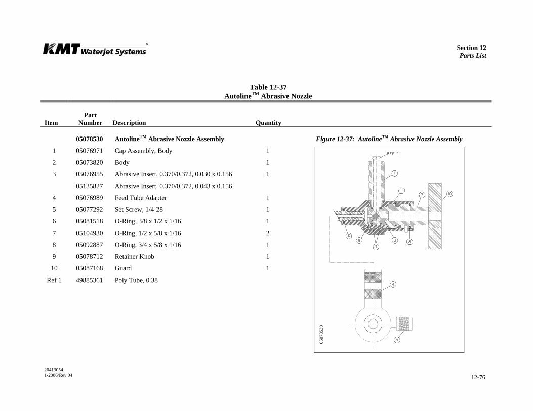
Section 12 Parts List
20413054 1-2006/Rev 04 12-76
Table 12-37 AutolineTM Abrasive Nozzle
Item
Part Number
Description
Quantity
05078530 AutolineTM Abrasive Nozzle Assembly Figure 12-37: AutolineTM Abrasive Nozzle Assembly
1 05076971 Cap Assembly, Body 1
2 05073820 Body 1
3 05076955 Abrasive Insert, 0.370/0.372, 0.030 x 0.156 1
05135827 Abrasive Insert, 0.370/0.372, 0.043 x 0.156
4 05076989 Feed Tube Adapter 1
5 05077292 Set Screw, 1/4-28 1
6 05081518 O-Ring, 3/8 x 1/2 x 1/16 1
7 05104930 O-Ring, 1/2 x 5/8 x 1/16 2
8 05092887 O-Ring, 3/4 x 5/8 x 1/16 1
9 05078712 Retainer Knob 1
10 05087168 Guard 1
Ref 1 49885361 Poly Tube, 0.38
0507
8530
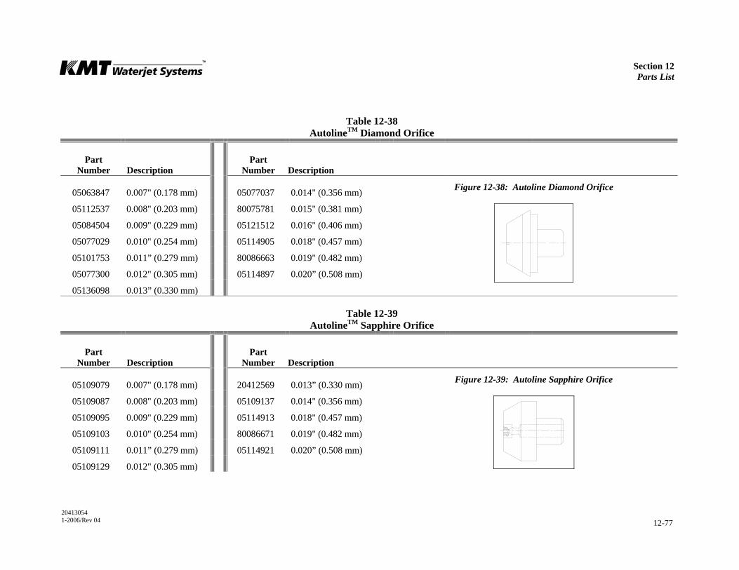
Section 12 Parts List
20413054 1-2006/Rev 04 12-77
Table 12-38 AutolineTM Diamond Orifice
Part Number
Description
Part Number
Description
05063847 0.007" (0.178 mm) 05077037 0.014" (0.356 mm) Figure 12-38: Autoline Diamond Orifice
05112537 0.008" (0.203 mm) 80075781 0.015" (0.381 mm)
05084504 0.009" (0.229 mm) 05121512 0.016" (0.406 mm)
05077029 0.010" (0.254 mm) 05114905 0.018" (0.457 mm)
05101753 0.011” (0.279 mm) 80086663 0.019" (0.482 mm)
05077300 0.012" (0.305 mm) 05114897 0.020” (0.508 mm)
05136098 0.013” (0.330 mm)
Table 12-39 AutolineTM Sapphire Orifice
Part Number
Description
Part Number
Description
05109079 0.007" (0.178 mm) 20412569 0.013” (0.330 mm) Figure 12-39: Autoline Sapphire Orifice
05109087 0.008" (0.203 mm) 05109137 0.014" (0.356 mm)
05109095 0.009" (0.229 mm) 05114913 0.018" (0.457 mm)
05109103 0.010" (0.254 mm) 80086671 0.019" (0.482 mm)
05109111 0.011” (0.279 mm) 05114921 0.020” (0.508 mm)
05109129 0.012" (0.305 mm)
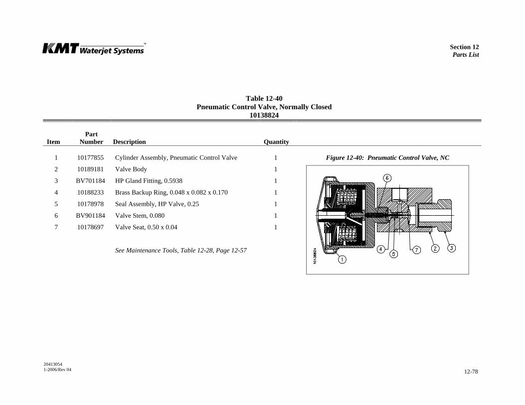
Section 12 Parts List
20413054 1-2006/Rev 04 12-78
Table 12-40 Pneumatic Control Valve, Normally Closed
10138824
Item
Part Number
Description
Quantity
1 10177855 Cylinder Assembly, Pneumatic Control Valve 1 Figure 12-40: Pneumatic Control Valve, NC
2 10189181 Valve Body 1
3 BV701184 HP Gland Fitting, 0.5938 1
4 10188233 Brass Backup Ring, 0.048 x 0.082 x 0.170 1
5 10178978 Seal Assembly, HP Valve, 0.25 1
6 BV901184 Valve Stem, 0.080 1
7 10178697 Valve Seat, 0.50 x 0.04 1
See Maintenance Tools, Table 12-28, Page 12-57
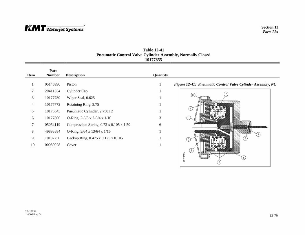
Section 12 Parts List
20413054 1-2006/Rev 04 12-79
Table 12-41 Pneumatic Control Valve Cylinder Assembly, Normally Closed
10177855
Item
Part Number
Description
Quantity
1 05145990 Piston 1 Figure 12-41: Pneumatic Control Valve Cylinder Assembly, NC
2 20411554 Cylinder Cap 1
3 10177780 Wiper Seal, 0.625 1
4 10177772 Retaining Ring, 2.75 1
5 10176543 Pneumatic Cylinder, 2.750 ID 1
6 10177806 O-Ring, 2-5/8 x 2-3/4 x 1/16 3
7 05054119 Compression Spring, 0.72 x 0.105 x 1.50 6
8 49895584 O-Ring, 5/64 x 13/64 x 1/16 1
9 10187250 Backup Ring, 0.475 x 0.125 x 0.105 1
10 00080028 Cover 1
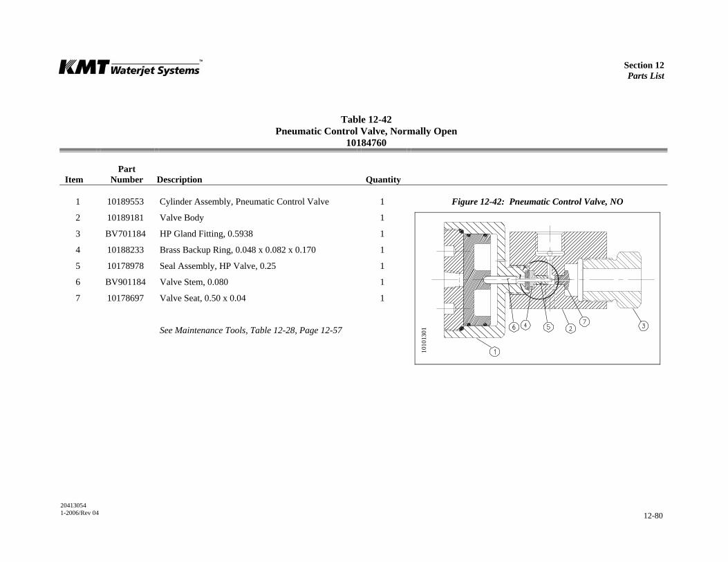
Section 12 Parts List
20413054 1-2006/Rev 04 12-80
Table 12-42 Pneumatic Control Valve, Normally Open
10184760
Item
Part Number
Description
Quantity
1 10189553 Cylinder Assembly, Pneumatic Control Valve 1 Figure 12-42: Pneumatic Control Valve, NO
2 10189181 Valve Body 1
3 BV701184 HP Gland Fitting, 0.5938 1
4 10188233 Brass Backup Ring, 0.048 x 0.082 x 0.170 1
5 10178978 Seal Assembly, HP Valve, 0.25 1
6 BV901184 Valve Stem, 0.080 1
7 10178697 Valve Seat, 0.50 x 0.04 1
See Maintenance Tools, Table 12-28, Page 12-57
1010
1301
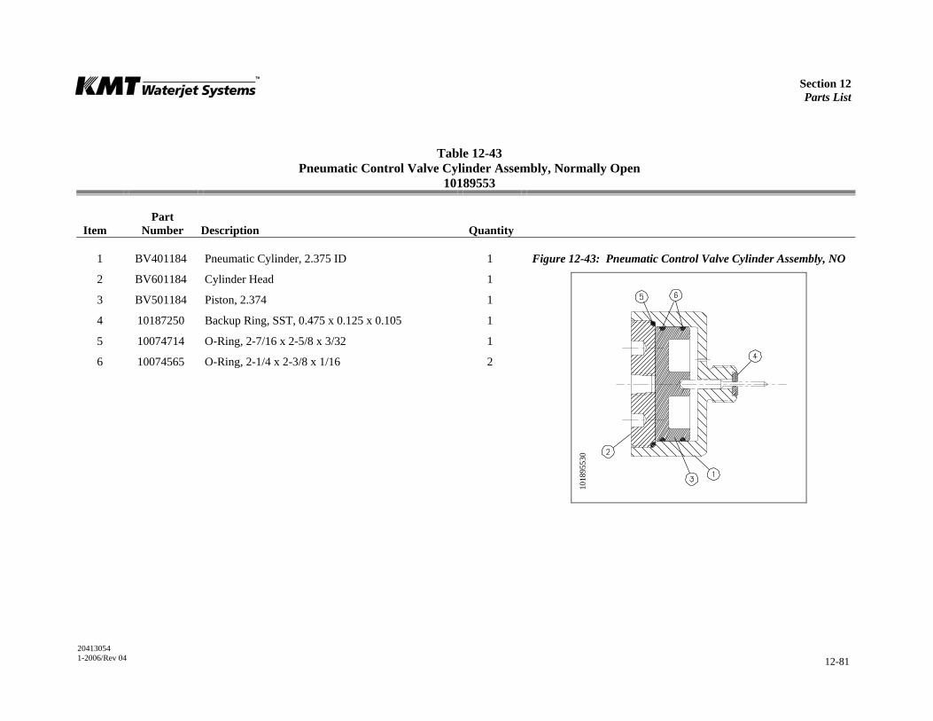
Section 12 Parts List
20413054 1-2006/Rev 04 12-81
Table 12-43 Pneumatic Control Valve Cylinder Assembly, Normally Open
10189553
Item
Part Number
Description
Quantity
1 BV401184 Pneumatic Cylinder, 2.375 ID 1 Figure 12-43: Pneumatic Control Valve Cylinder Assembly, NO
2 BV601184 Cylinder Head 1
3 BV501184 Piston, 2.374 1
4 10187250 Backup Ring, SST, 0.475 x 0.125 x 0.105 1
5 10074714 O-Ring, 2-7/16 x 2-5/8 x 3/32 1
6 10074565 O-Ring, 2-1/4 x 2-3/8 x 1/16 2
1018
9553
0

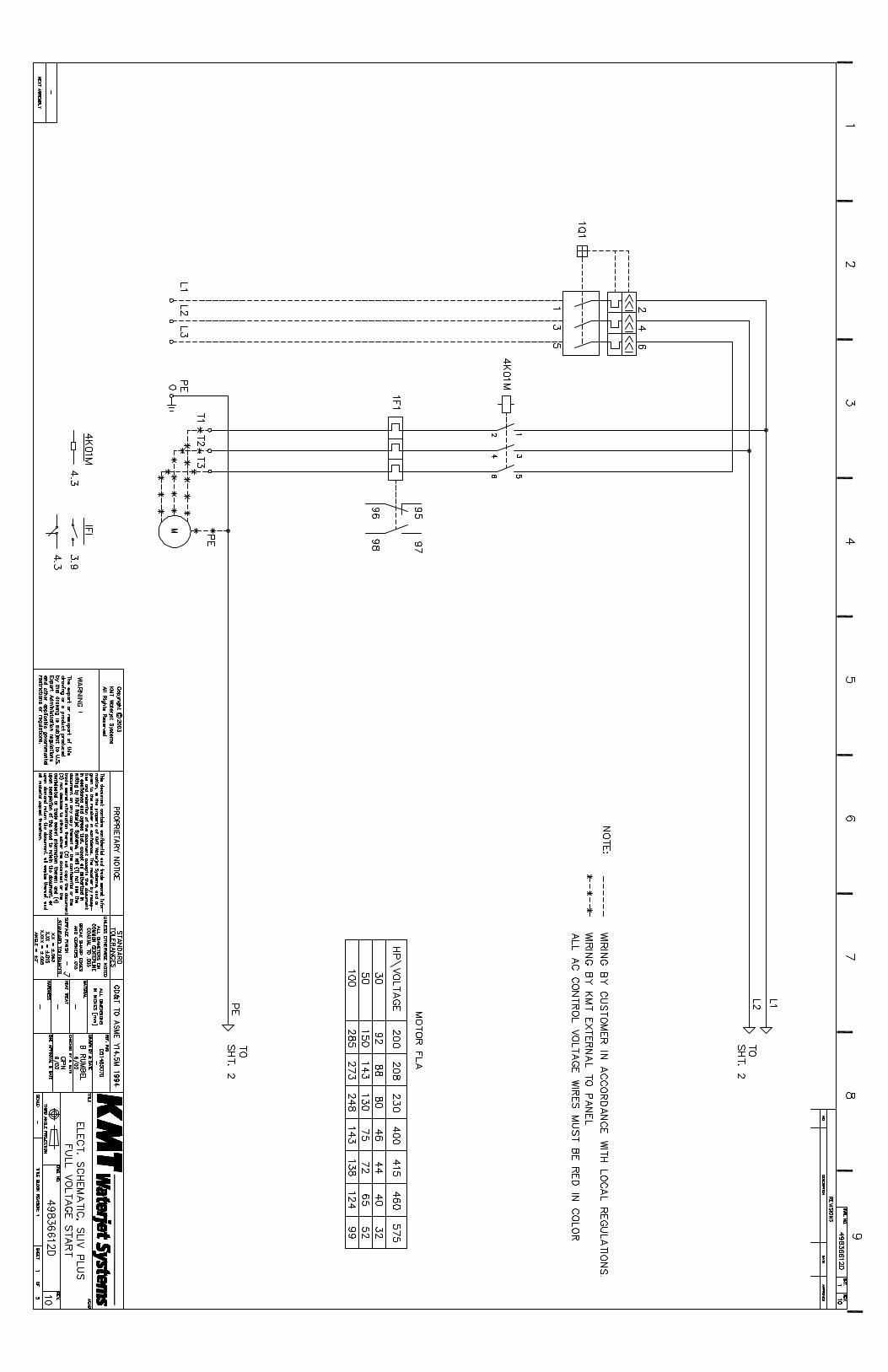
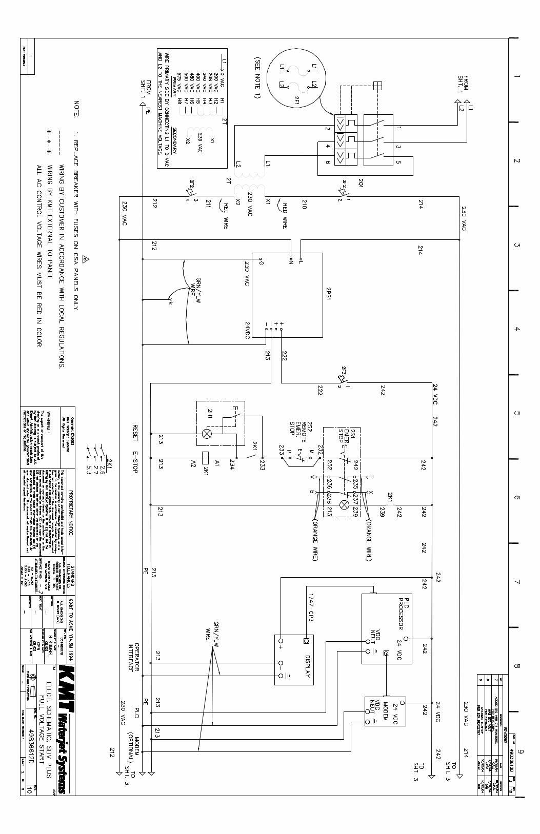
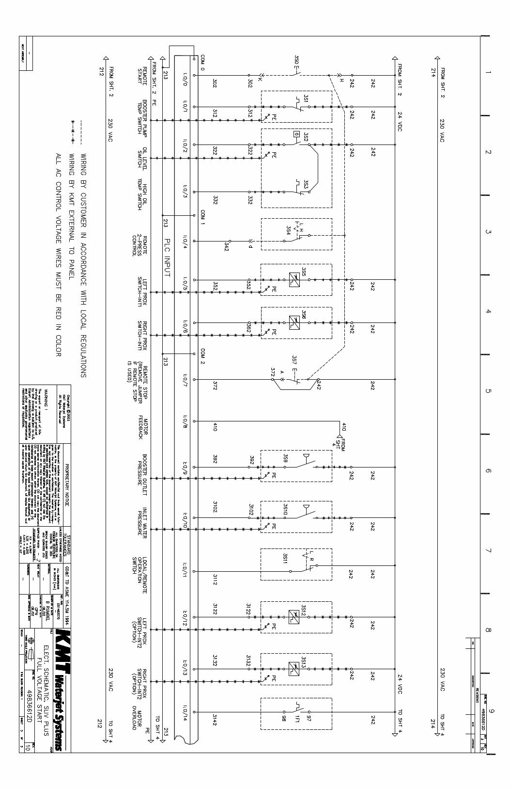
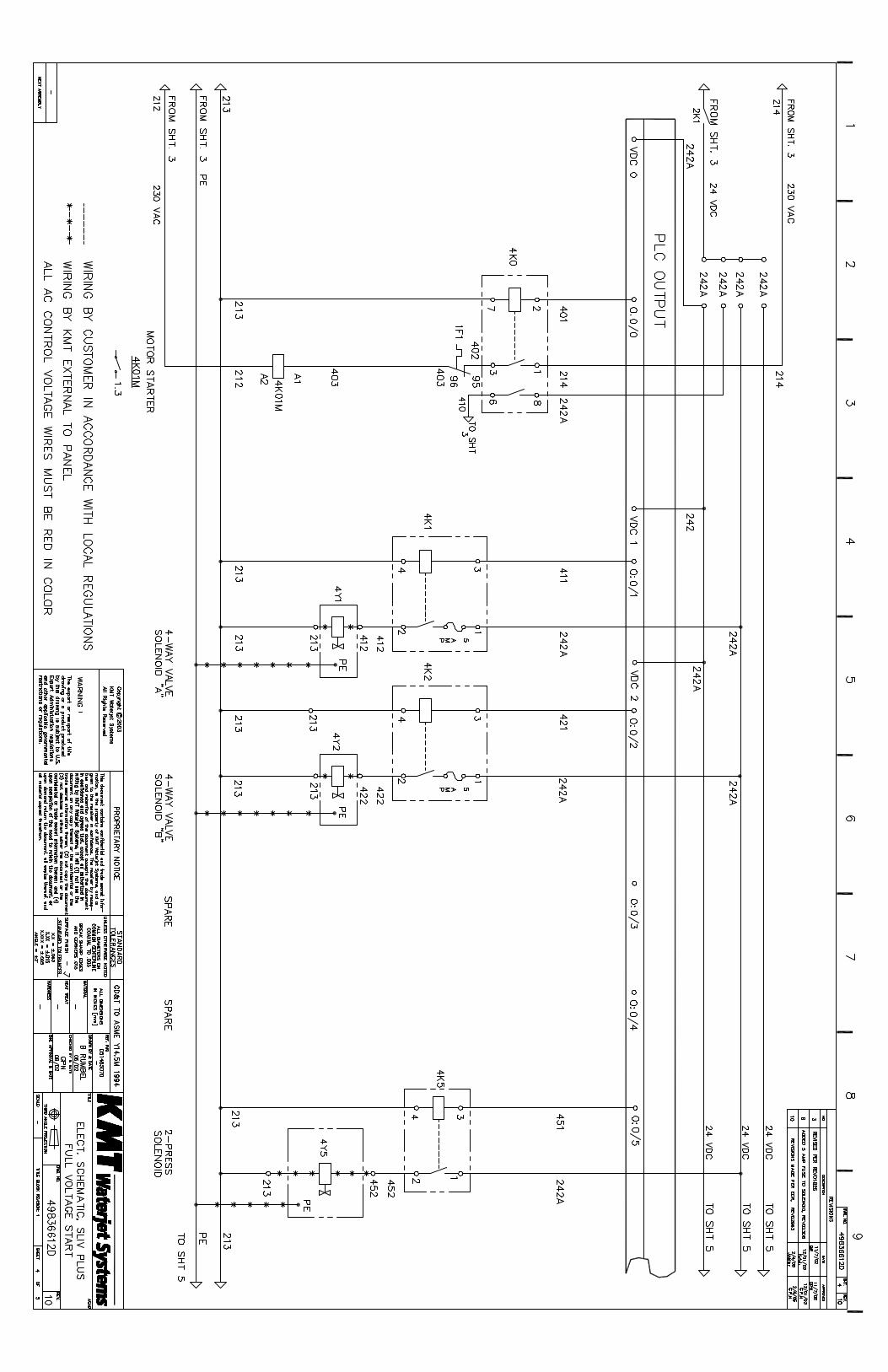
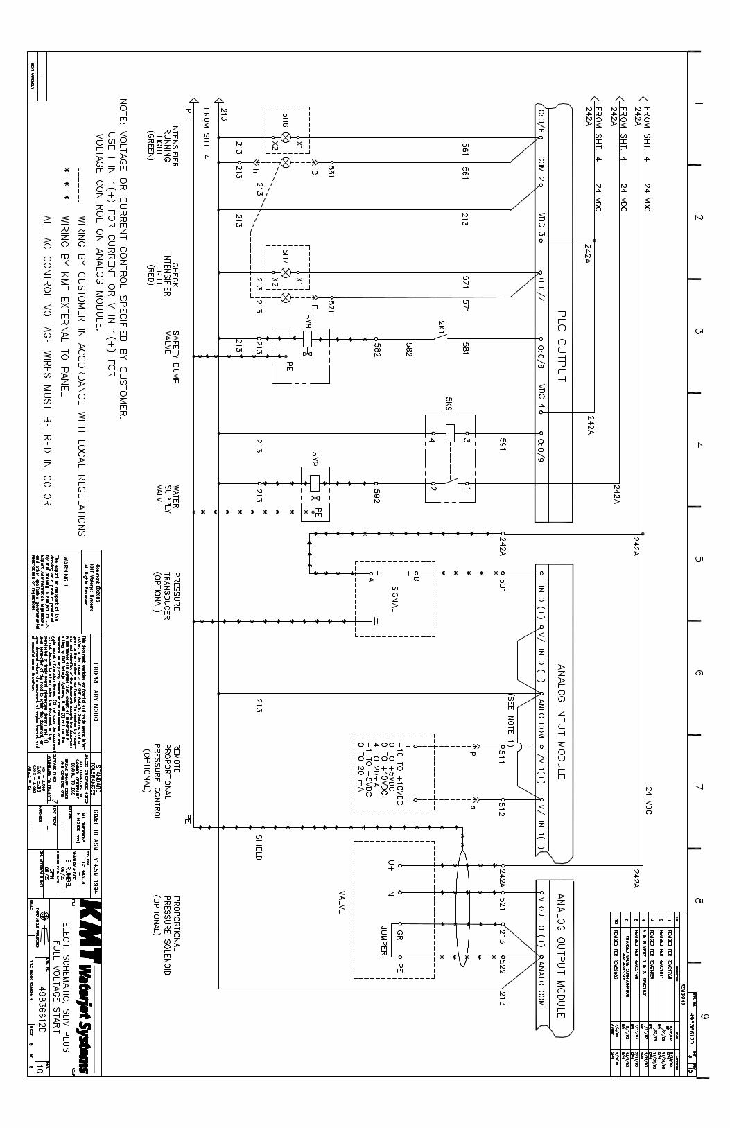
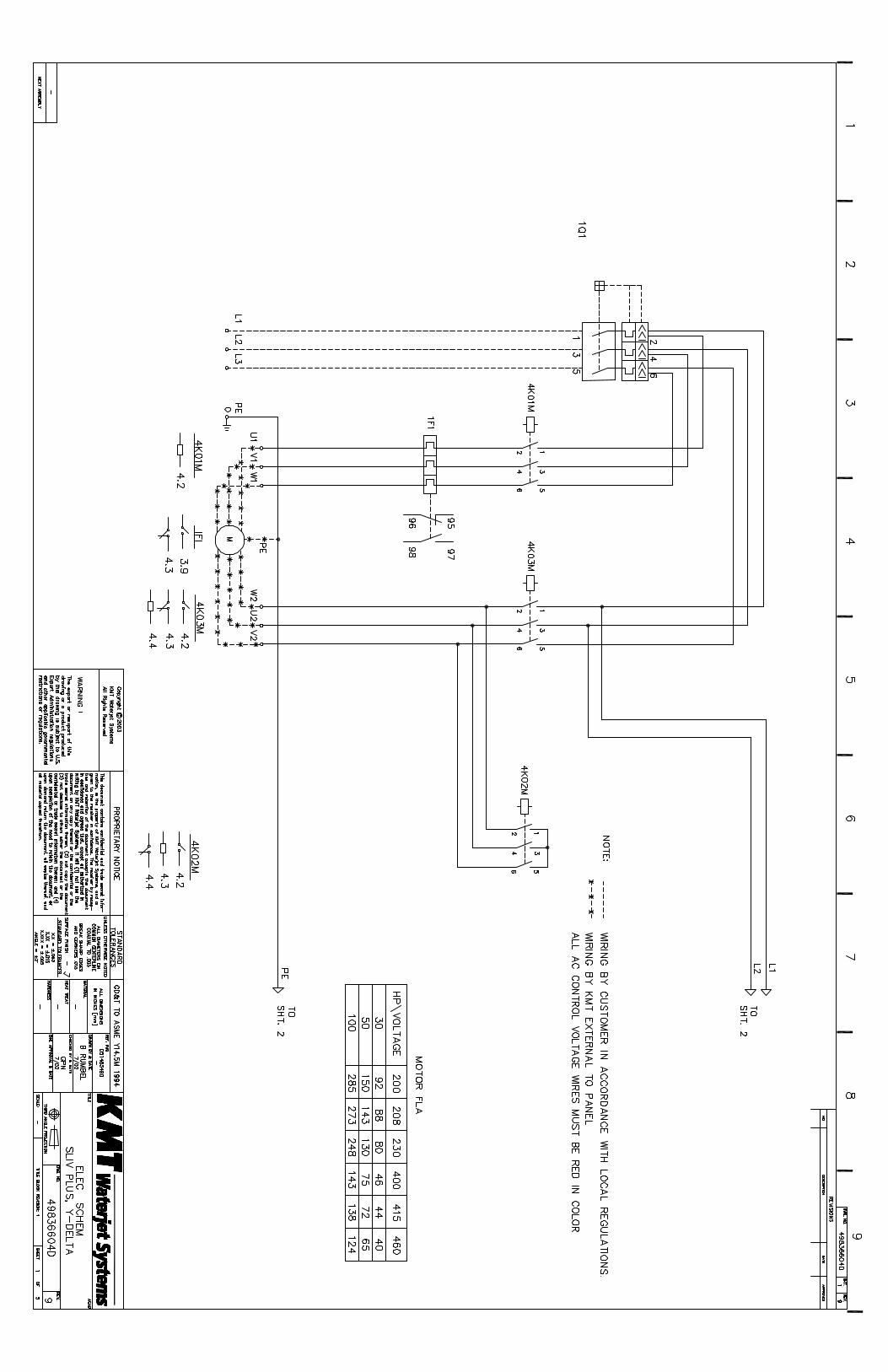
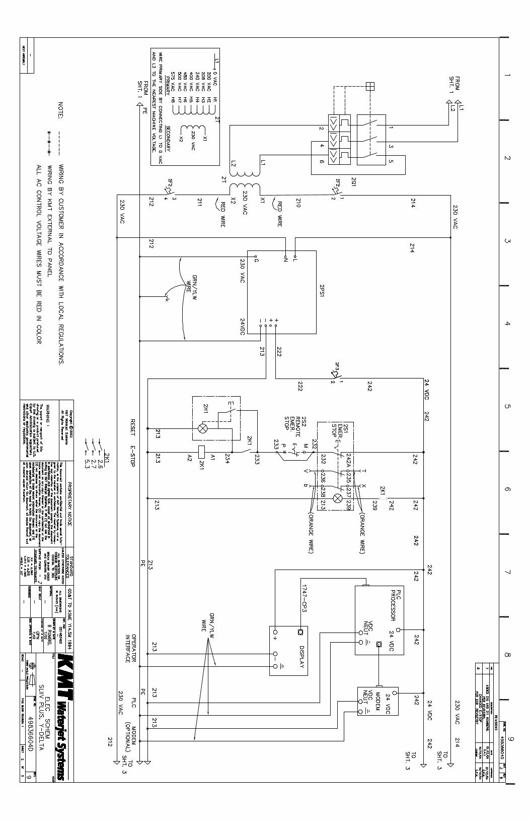
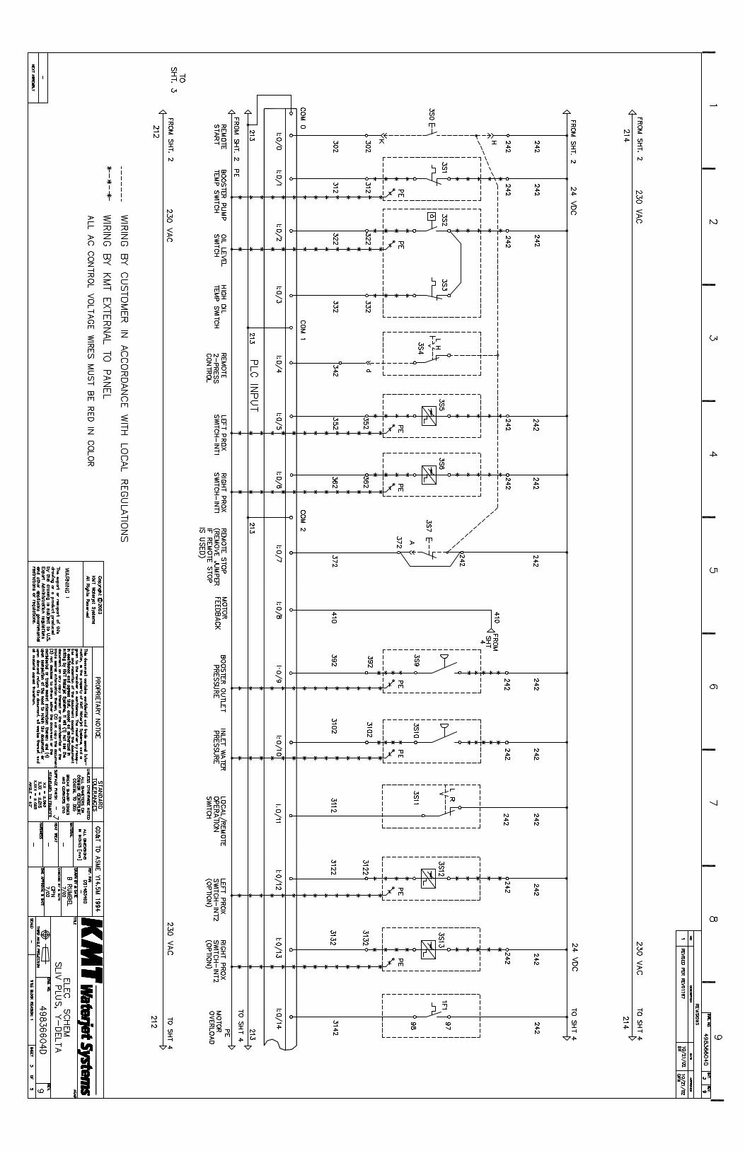
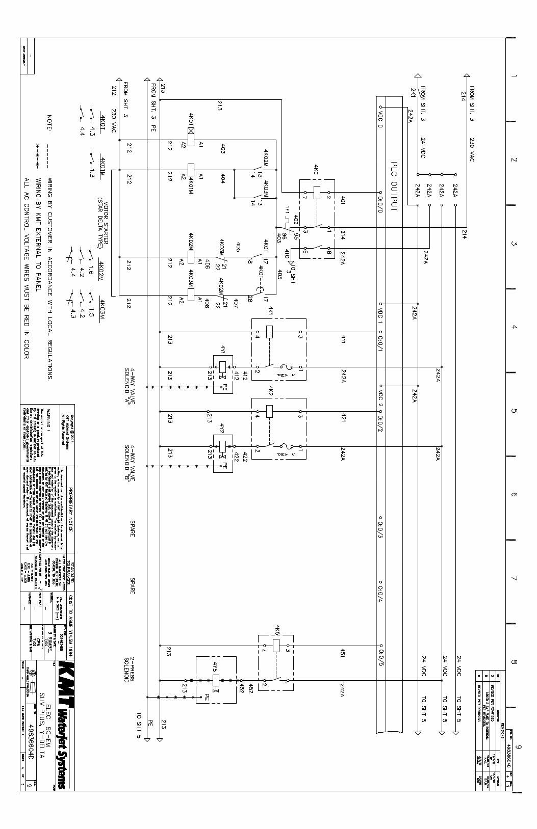
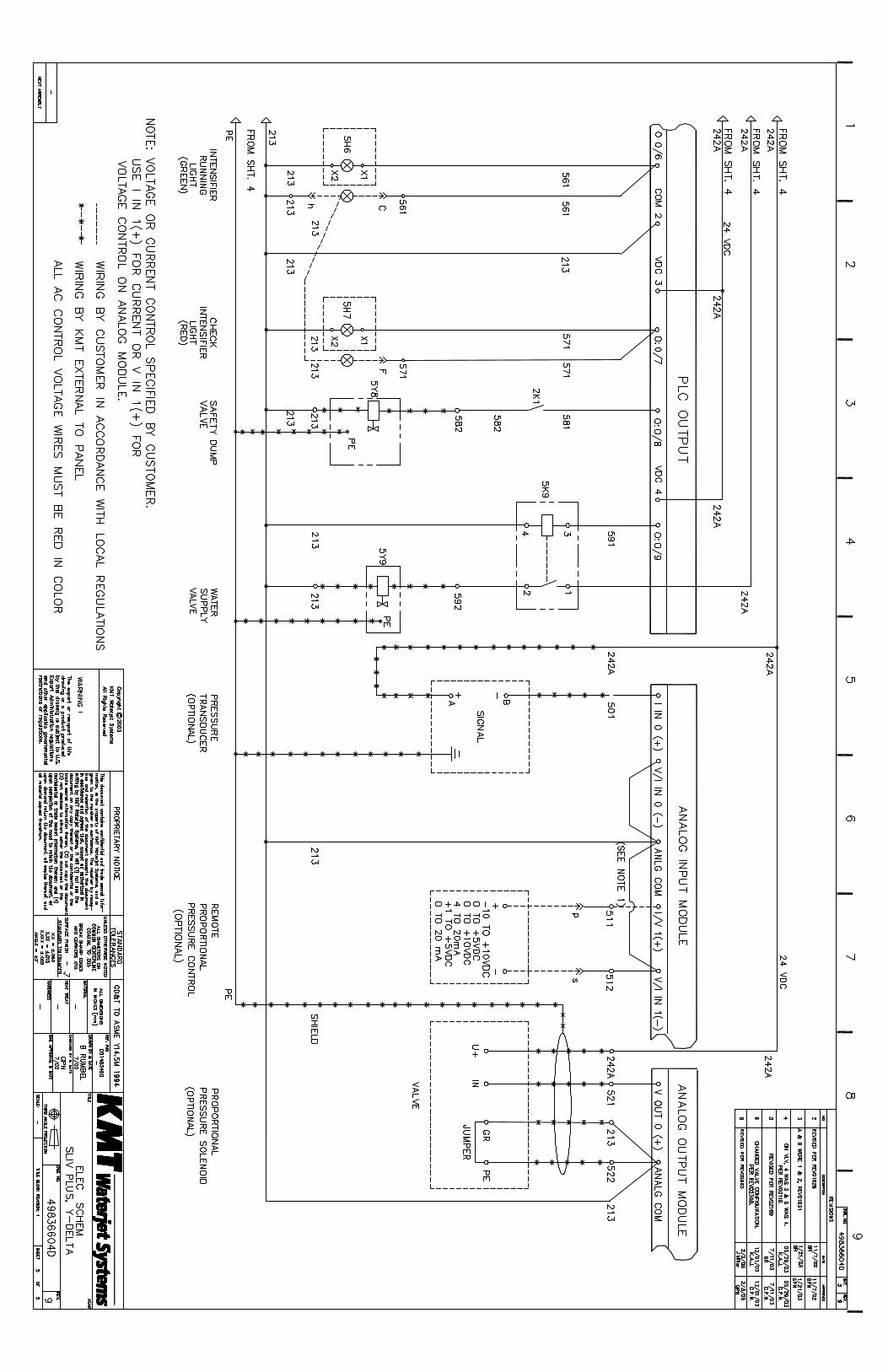


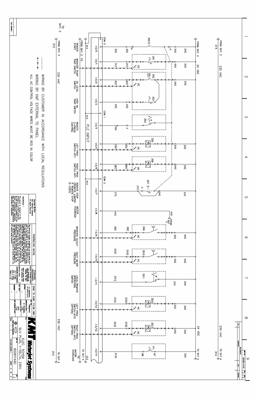
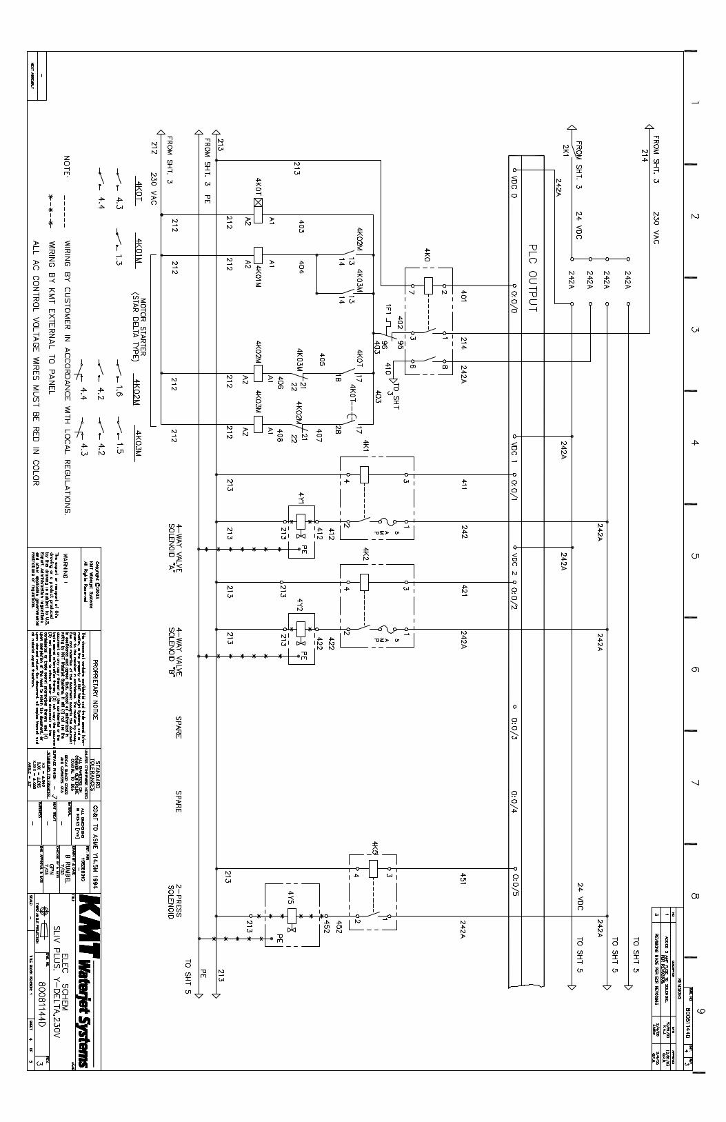

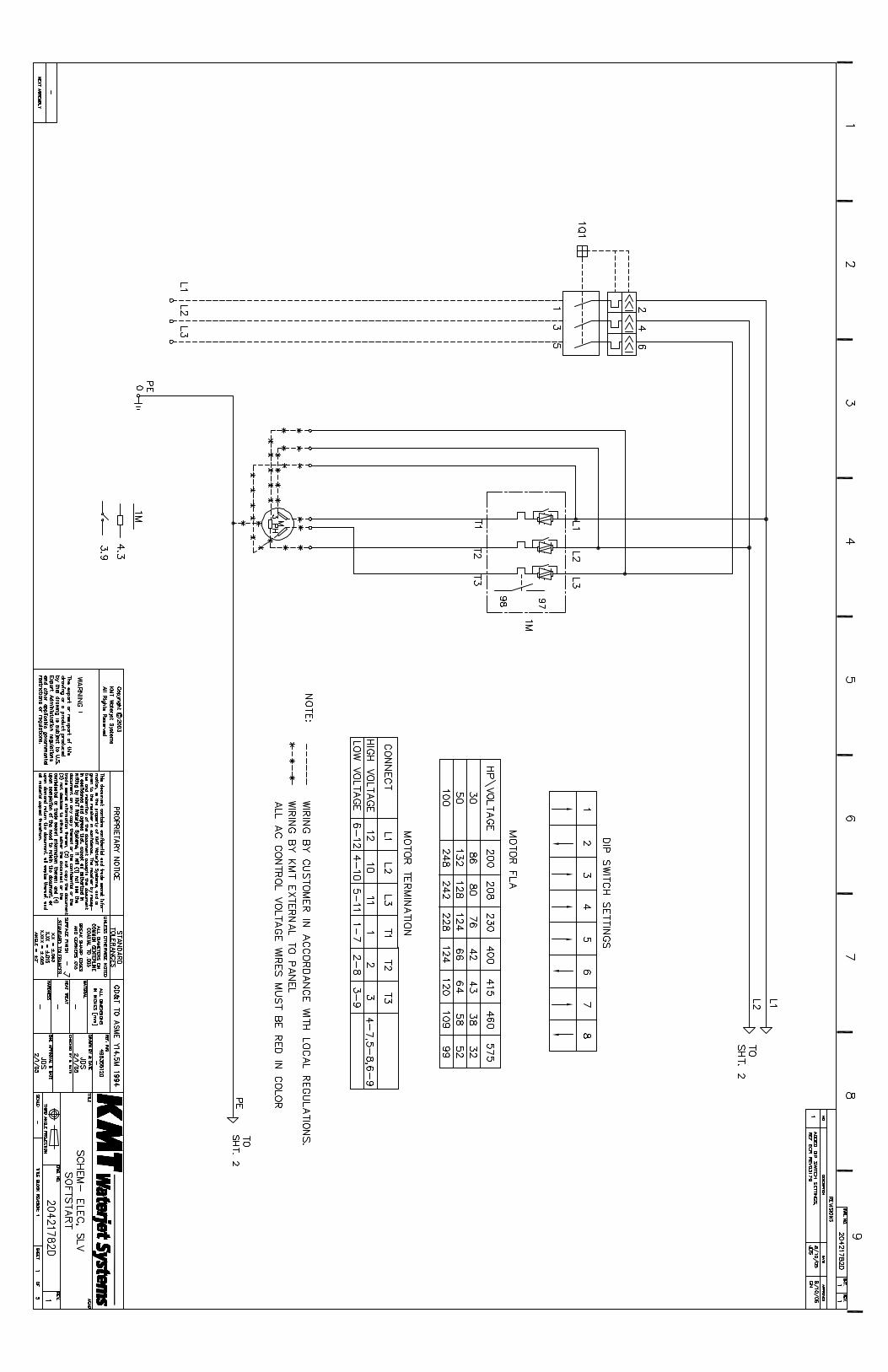
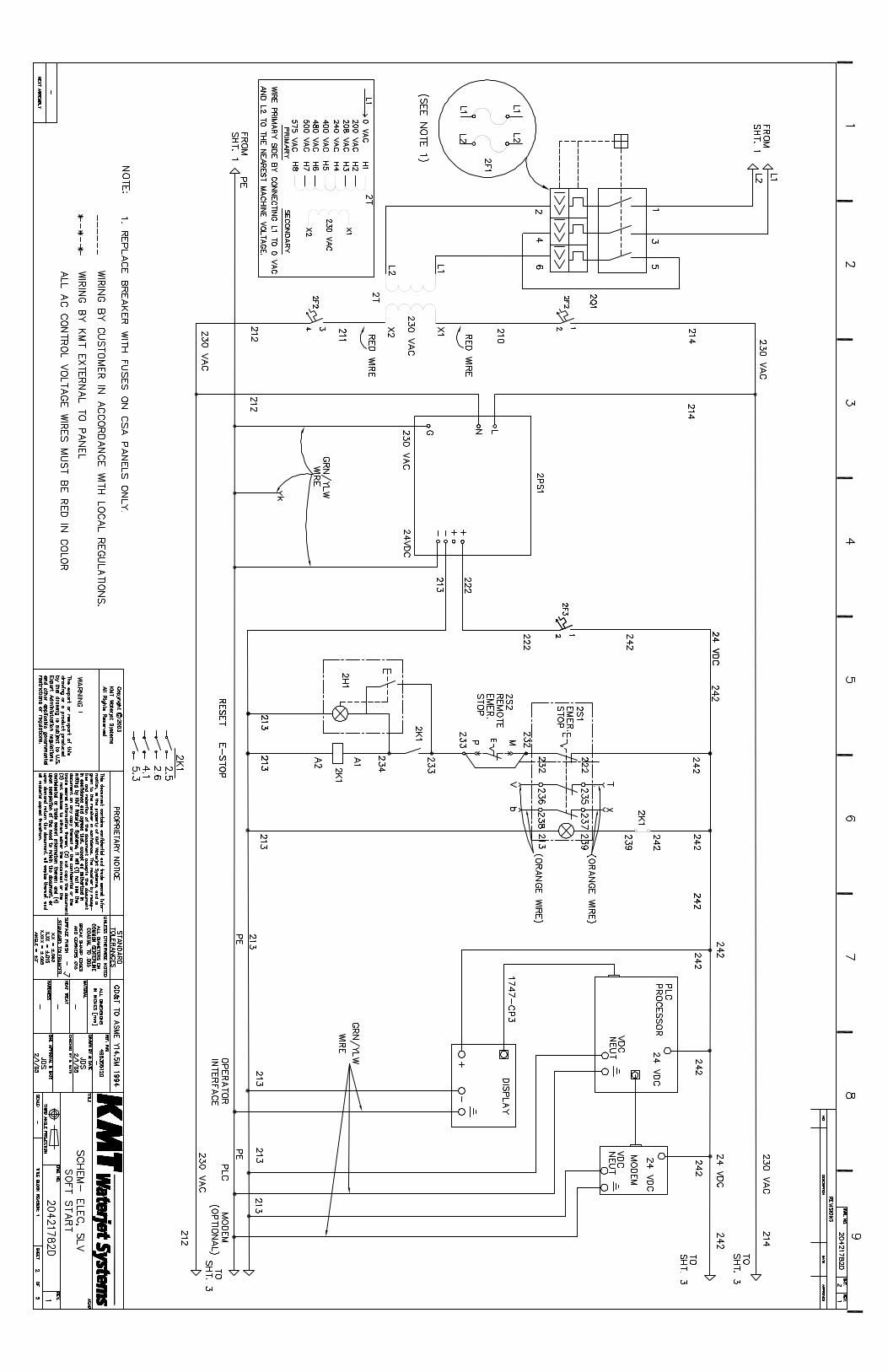


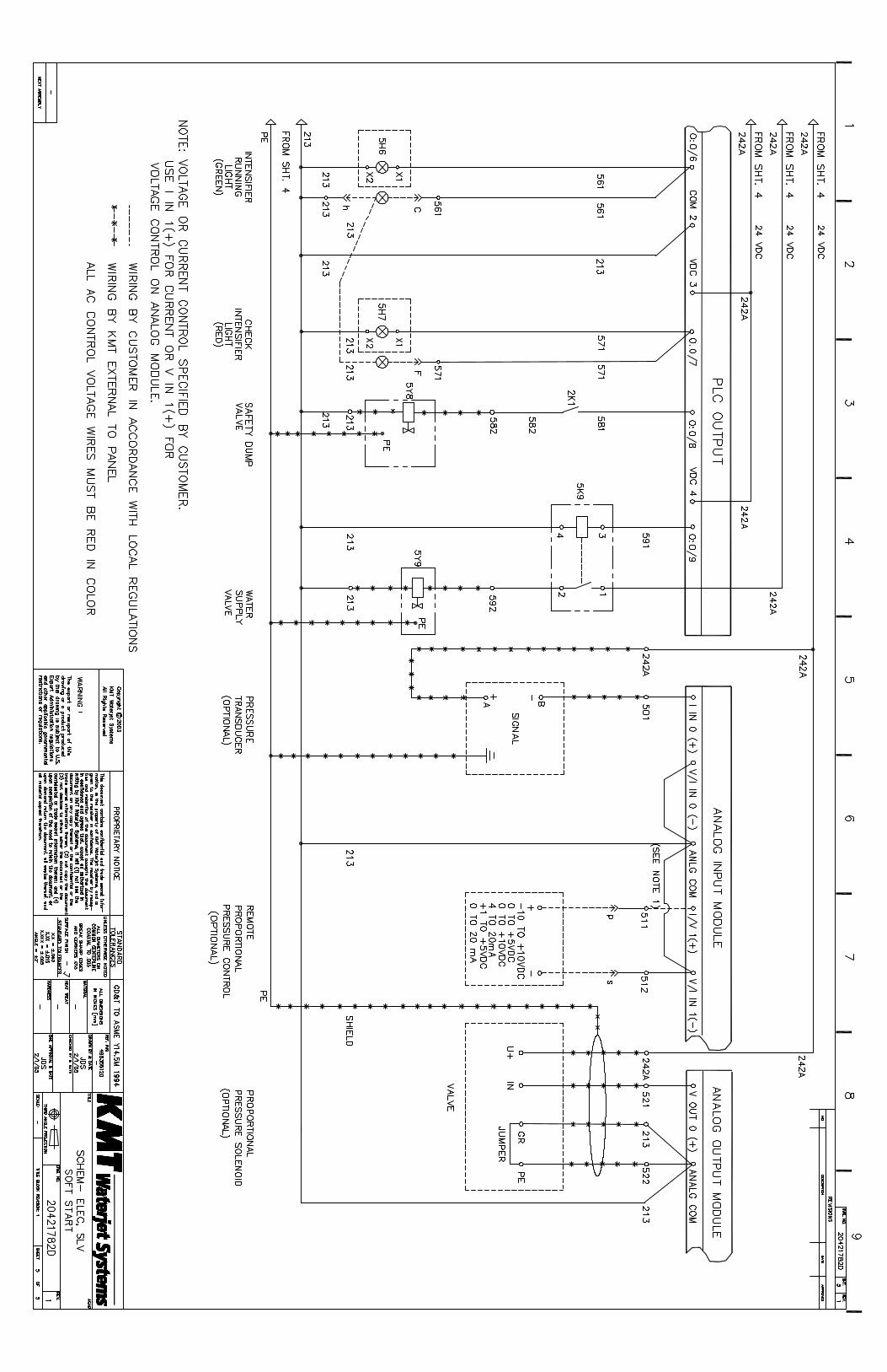
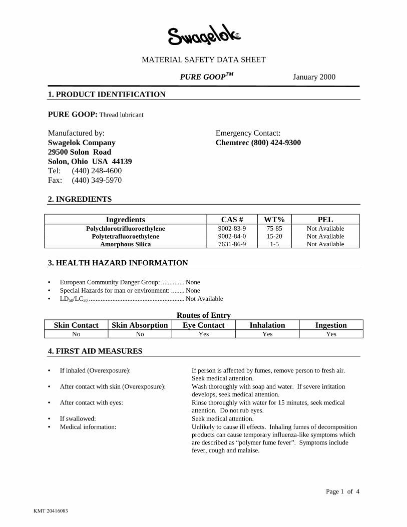
MATERIAL SAFETY DATA SHEET
PURE GOOPTM January 2000
Page 1 of 4
1. PRODUCT IDENTIFICATION
PURE GOOP: Thread lubricant
Manufactured by: Emergency Contact:Swagelok Company Chemtrec (800) 424-930029500 Solon RoadSolon, Ohio USA 44139Tel: (440) 248-4600Fax: (440) 349-5970
2. INGREDIENTS
Ingredients CAS # WT% PELPolychlorotrifluoroethylene 9002-83-9 75-85 Not Available
Polytetrafluoroethylene 9002-84-0 15-20 Not AvailableAmorphous Silica 7631-86-9 1-5 Not Available
3. HEALTH HAZARD INFORMATION
• European Community Danger Group: .............. None• Special Hazards for man or environment: ........ None• LD50/LC50 ......................................................... Not Available
Routes of EntrySkin Contact Skin Absorption Eye Contact Inhalation Ingestion
No No Yes Yes Yes
4. FIRST AID MEASURES
• If inhaled (Overexposure): If person is affected by fumes, remove person to fresh air.Seek medical attention.
• After contact with skin (Overexposure): Wash thoroughly with soap and water. If severe irritationdevelops, seek medical attention.
• After contact with eyes: Rinse thoroughly with water for 15 minutes, seek medicalattention. Do not rub eyes.
• If swallowed: Seek medical attention.• Medical information: Unlikely to cause ill effects. Inhaling fumes of decomposition
products can cause temporary influenza-like symptoms whichare described as “polymer fume fever”. Symptoms includefever, cough and malaise.
KMT 20416083

MATERIAL SAFETY DATA SHEET
PURE GOOPTM January 2000
Page 2 of 4
5. FIRE FIGHTING MEASURES
• Suitable extinguishing agents: Carbon dioxide, foam, agent suitable for environment.• Not suitable for safety reasons: None known.
• Special dangers caused by substance May decompose above 500°°°°F/260°°°°C to produce organo-chlorinepreparation itself, by combustion compounds, organo-fluorine compounds, hydrogen fluoride, andproducts or gases formed: chlorine gas.
• Additional information: None.
Autoignition UEL LEL SensitivitiesNot Applicable Not Available Not Available Not Available
6. ACCIDENTAL RELEASE MEASURES
• Measures for protection of people: Put on necessary protective equipment. Eye and hand protection asneeded.
• Measures for protection of theenvironment: None required.
• Cleaning measures: Use absorbent material and suitable cleaner.• Additional information: None.
7. HANDLING AND STORAGE
• Safety information: None.• Information on protection from fire May decompose above 500°°°°F/260°°°°C to produce organo-chlorine
or explosion: compounds, organo-fluorine compounds, hydrogen fluoride, andchlorine gas.
• Additional information: Store in a cool, dry place for optimal product performance.
8. EXPOSURE CONTROLS AND PERSONAL PROTECTION
• Precautionary measures to protectemployees: None required.
• Respiratory protection: None required.• Hand protection: Rubber gloves are recommended to minimize exposure.• Eye protection: Safety glasses or goggles are recommended to minimize exposure.• Skin protection: Wash hands after use.
KMT 20416083
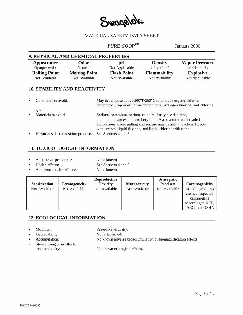
MATERIAL SAFETY DATA SHEET
PURE GOOPTM January 2000
Page 3 of 4
9. PHYSICAL AND CHEMICAL PROPERTIESAppearance Odor pH Density Vapor PressureOpaque-white Neutral Not Applicable 2.1 gm/cm3 <0.01mm Hg
Boiling Point Melting Point Flash Point Flammability ExplosiveNot Available Not Available Not Available Not Available Not Applicable
10. STABILITY AND REACTIVITY
• Conditions to avoid: May decompose above 500°°°°F/260°°°°C to produce organo-chlorinecompounds, organo-fluorine compounds, hydrogen fluoride, and chlorine
gas.• Materials to avoid: Sodium, potassium, barium, calcium, finely divided zinc,
aluminum, magnesium, and beryllium. Avoid aluminum threadedconnections where galling and seizure may initiate a reaction. Reactswith amines, liquid fluorine, and liquid chlorine trifluoride.
• Hazardous decomposition products: See Sections 4 and 5.
11. TOXICOLOGICAL INFORMATION
• Acute toxic properties: None known.• Health effects: See Sections 4 and 5.• Additional health effects: None known.
Sensitization TeratogenicityReproductive
Toxicity MutagenicitySynergisticProducts Carcinogenicity
Not Available Not Available Not Available Not Available Not Available Listed ingredientsare not suspected
carcinogensaccording to NTP,IARC, and OSHA
12. ECOLOGICAL INFORMATION
• Mobility: Paste-like viscosity.• Degradability: Not established.• Accumulation: No known adverse bioaccumulation or biomagnification effects.• Short / Long term effects
on ecotoxicity: No known ecological effects.
KMT 20416083

MATERIAL SAFETY DATA SHEET
PURE GOOPTM January 2000
Page 4 of 4
13. DISPOSAL CONSIDERATIONS
• Appropriate methods of disposal: Unused product not considered a hazardous waste in the United States.Dispose of in a responsible manner.
• European Community(EC)considerations: Use appropriate waste codes based on ingredients.
14. TRANSPORT INFORMATION
• Transport precautions: Consult applicable regulations when transporting this product.• Additional information: None.
15. REGULATORY INFORMATION
• EC regulations: This product has been classified under CHIP-96 guidelines based onchemical content.
• US/Canadian regulation listings: SARA 313 - NO, TSCA - YES, Canada’s Controlled Products - NO• EC Relevant risk: None.• EC Relevant safety: S: 37/39 - Wear suitable gloves and eye/face protection.
S:20 - When using do not eat or drink.• Additional information: Consult country codes for specific requirements.
16. OTHER INFORMATION
• Further information contact: Your Swagelok Distributor or the contacts listed in Section 1 of this sheet.• Sources of information used Properties of individual ingredients were used to compile this document.
to compile document: This Material Safety Data Sheet was designed to give the distributorsand users of PURE GOOP information to handle and use the product ina responsible manner.
Preparation DataEnvironmental and Safety Department (440) 349-5955 January 2000
KMT 20416083

LOCTITE CANADA INC. 01/15/02 MISSISSAUGA, ONTARIO L5N 7P2 TELEPHONE: (905) 814-6511 FAX: (905) 814-5391
CANADIAN WORKPLACE HAZARDOUS MATERIALS INFORMATION SYSTEM Page 01 of 04
Loctite(R) 222 Threadlocker Low Strength 21464
I. PRODUCT IDENTIFICATION
Product Name: Loctite(R) 222 Threadlocker Low Strength Item No.: 21464 Product Use: Adhesive/Sealant Formula No.: LI-256
II. HAZARDOUS INGREDIENTS
Ingredients % by Weight CAS No.
Polyglycol dimethacrylate 45-50 25852-47-5 Polyglycol oleate 35-40 9004-96-0 Saccharin 3-5 81-07-2 Silica, amorphous, treated 3-5 68909-20-6 CUMENE HYDROPEROXIDE 1-3 80-15-9 Propylene glycol 1-3 57-55-6 N,N-Dialkyltoluidines 0.1-1 613-48-9 TITANIUM DIOXIDE 0.1-1 13463-67-7
III. PHYSICAL DATA
Physical State/Appearance: Purple liquid Odour & Odour Threshold: Mild Specific Gravity: 1.08 at 68°F Vapour Pressure: Less than 5mm at 80°F Vapour Density: Not Available Evaporation Rate: (Ether = 1) Not Available Boiling Point: Greater than 300°F Freezing Point: Not Available Volatile Organic Compound (EPA Method 24) 11.8%; 127 grams per liter pH: Not Applicable Coefficient of water/oil distribution: Not Available
IV. FIRE OR EXPLOSIVE HAZARD
Conditions of Flammability: None Means of Extinction: Carbon Dioxide, Foam, Dry Chemical Flashpoint (Method): Greater than 200°F Method: Tag Closed Cup Upper Flammable Limit: Methanol: 36% Lower Flammable Limit: Methanol: 6% Auto-Ignition Temperature: Not Available
KMT 20416099

LOCTITE CANADA INC. 01/15/02 MISSISSAUGA, ONTARIO L5N 7P2 TELEPHONE: (905) 814-6511 FAX: (905) 814-5391
CANADIAN WORKPLACE HAZARDOUS MATERIALS INFORMATION SYSTEM Page 02 of 04
Product Name: Loctite(R) 222 Threadlocker Low Strength Item No.: 21464
IV. FIRE OR EXPLOSIVE HAZARD (continued)
Hazardous Combustion Products: Irritating organic vapors. Explosion Data - Sensiti- vity to Static Discharge: Not Applicable
V. REACTIVITY DATA
Conditions causing Chemical Instability: None Substances with which the Product is Unstable: None Conditions of Reactivity: None Hazardous Decomposition Products: None
VI. TOXICOLOGICAL PRODUCTS
Route(s) of Entry: None Known Existing Conditions Aggravated by Exposure: None Known Toxicity Information: (See Effects of Acute Exposure to Product) Effects of Acute Exposure to Product: Mild eye irritant. Estimated oral LD50 more than 5000 mg/kg. Estimated dermal LD50 more than 2000 mg/kg. Effects of Chronic Exposure to Product:
Literature Referenced Carcinogen Ingredients Target Organ and Other Health Effects NTP IARC OSHA
Polyglycol dimethacrylate ALG IRR NO NO NO Polyglycol oleate IRR NO NO NO Saccharin NTO NO N/A NO Silica, amorphous, treated NTO NO NO NO CUMENE HYDROPEROXIDE ALG CNS COR IRR MUT NO NO NO Propylene glycol IRR NO NO NO N,N-Dialkyltoluidines NTO NO NO NO TITANIUM DIOXIDE IRR RES NO NO NO -------------------------------------------------------------------------------
Abbreviations
N/A Not Applicable ALG Allergen CNS Central nervous system COR Corrosive IRR Irritant MUT Mutagen NTO No Target Organs RES Respiratory
KMT 20416099
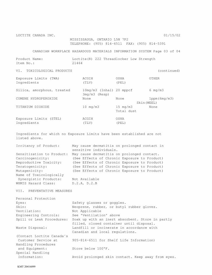
LOCTITE CANADA INC. 01/15/02 MISSISSAUGA, ONTARIO L5N 7P2 TELEPHONE: (905) 814-6511 FAX: (905) 814-5391
CANADIAN WORKPLACE HAZARDOUS MATERIALS INFORMATION SYSTEM Page 03 of 04
Product Name: Loctite(R) 222 Threadlocker Low Strength Item No.: 21464
VI. TOXICOLOGICAL PRODUCTS (continued)
Exposure Limits (TWA) ACGIH OSHA OTHER Ingredients (TLV) (PEL)
Silica, amorphous, treated 10mg/m3 (Inhal) 20 mppcf 6 mg/m3 3mg/m3 (Resp) CUMENE HYDROPEROXIDE None None 1ppm(6mg/m3) Skin(WEEL) TITANIUM DIOXIDE 10 mg/m3 15 mg/m3 None Total dust
Exposure Limits (STEL) ACGIH OSHA Ingredients (TLV) (PEL)
Ingredients for which no Exposure Limits have been established are not listed above.
Irritancy of Product: May cause dermatitis on prolonged contact in sensitive individuals. Sensitization to Product: May cause dermatitis on prolonged contact. Carcinogenicity: (See Effects of Chronic Exposure to Product) Reproductive Toxicity: (See Effects of Chronic Exposure to Product) Teratogenicity: (See Effects of Chronic Exposure to Product) Mutagenicity: (See Effects of Chronic Exposure to Product) Name of Toxicologically Synergistic Products: Not Available WHMIS Hazard Class: D.2.A, D.2.B
VII. PREVENTATIVE MEASURES
Personal Protection Eyes: Safety glasses or goggles. Skin: Neoprene, rubber, or butyl rubber gloves. Ventilation: Not Applicable Engineering Controls: See "Ventilation" above Spill or Leak Procedures: Soak up with an inert absorbent. Store in partly filled, closed container until disposal. Waste Disposal: Landfill or incinerate in accordance with Canadian and local regulations. (Contact Loctite Canada's Customer Service at 905-814-6511 for Shelf Life Information) Handling Procedures and Equipment: Store below 100°F. Special Handling Information: Avoid prolonged skin contact. Keep away from eyes.
KMT 20416099

LOCTITE CANADA INC. 01/15/02 MISSISSAUGA, ONTARIO L5N 7P2 TELEPHONE: (905) 814-6511 FAX: (905) 814-5391
CANADIAN WORKPLACE HAZARDOUS MATERIALS INFORMATION SYSTEM Page 04 of 04
Product Name: Loctite(R) 222 Threadlocker Low Strength Item No.: 21464
VIII. FIRST AID MEASURES
Ingestion: Do not induce vomiting. Keep individual calm. Obtain medical attention. Inhalation: Not Applicable Skin Contact: Wash with soap and water. Eye Contact: Flush at least 15 minutes with water. Obtain medical attention.
IX. SHIPPING INFORMATION
Canadian Transportation of Dangerous Goods: Shipping Name NOT REGULATED Classification NOT REGULATED Product ID Number NONE ICAO/IATA: Proper Shipping Name Unrestricted Class or Division Unrestricted UN or ID Number None
X. PREPARATION INFORMATION
Prepared By: Stephen Repetto Title: Research Chemist, Environmental Health & Safety Emergency Phone Number: (860) 571-5100 Revision Date: December 15, 2001 Revision: 0004
KMT 20416099
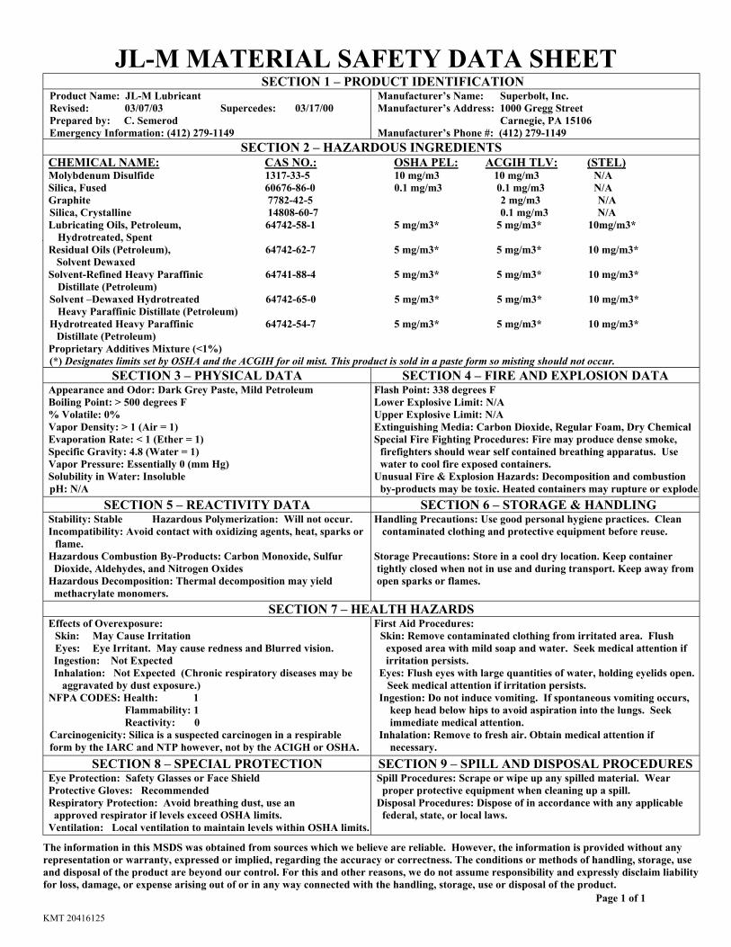
JL-M MATERIAL SAFETY DATA SHEET
Page 1 of 1
SECTION 1 – PRODUCT IDENTIFICATION Product Name: JL-M Lubricant Revised: 03/07/03 Supercedes: 03/17/00 Prepared by: C. Semerod Emergency Information: (412) 279-1149
Manufacturer’s Name: Superbolt, Inc. Manufacturer’s Address: 1000 Gregg Street Carnegie, PA 15106 Manufacturer’s Phone #: (412) 279-1149
SECTION 2 – HAZARDOUS INGREDIENTS CHEMICAL NAME: CAS NO.: OSHA PEL: ACGIH TLV: (STEL) Molybdenum Disulfide 1317-33-5 10 mg/m3 10 mg/m3 N/A Silica, Fused 60676-86-0 0.1 mg/m3 0.1 mg/m3 N/A Graphite 7782-42-5 2 mg/m3 N/A Silica, Crystalline 14808-60-7 0.1 mg/m3 N/A Lubricating Oils, Petroleum, 64742-58-1 5 mg/m3* 5 mg/m3* 10mg/m3* Hydrotreated, Spent Residual Oils (Petroleum), 64742-62-7 5 mg/m3* 5 mg/m3* 10 mg/m3* Solvent Dewaxed Solvent-Refined Heavy Paraffinic 64741-88-4 5 mg/m3* 5 mg/m3* 10 mg/m3* Distillate (Petroleum) Solvent –Dewaxed Hydrotreated 64742-65-0 5 mg/m3* 5 mg/m3* 10 mg/m3* Heavy Paraffinic Distillate (Petroleum) Hydrotreated Heavy Paraffinic 64742-54-7 5 mg/m3* 5 mg/m3* 10 mg/m3* Distillate (Petroleum) Proprietary Additives Mixture (<1%) (*) Designates limits set by OSHA and the ACGIH for oil mist. This product is sold in a paste form so misting should not occur.
SECTION 3 – PHYSICAL DATA SECTION 4 – FIRE AND EXPLOSION DATA Appearance and Odor: Dark Grey Paste, Mild Petroleum Boiling Point: > 500 degrees F % Volatile: 0% Vapor Density: > 1 (Air = 1) Evaporation Rate: < 1 (Ether = 1) Specific Gravity: 4.8 (Water = 1) Vapor Pressure: Essentially 0 (mm Hg) Solubility in Water: Insoluble pH: N/A
Flash Point: 338 degrees F Lower Explosive Limit: N/A Upper Explosive Limit: N/A Extinguishing Media: Carbon Dioxide, Regular Foam, Dry Chemical Special Fire Fighting Procedures: Fire may produce dense smoke,
firefighters should wear self contained breathing apparatus. Use water to cool fire exposed containers.
Unusual Fire & Explosion Hazards: Decomposition and combustion by-products may be toxic. Heated containers may rupture or explode.
SECTION 5 – REACTIVITY DATA SECTION 6 – STORAGE & HANDLING Stability: Stable Hazardous Polymerization: Will not occur. Incompatibility: Avoid contact with oxidizing agents, heat, sparks or flame. Hazardous Combustion By-Products: Carbon Monoxide, Sulfur Dioxide, Aldehydes, and Nitrogen Oxides Hazardous Decomposition: Thermal decomposition may yield methacrylate monomers.
Handling Precautions: Use good personal hygiene practices. Clean contaminated clothing and protective equipment before reuse.
Storage Precautions: Store in a cool dry location. Keep container tightly closed when not in use and during transport. Keep away from open sparks or flames.
SECTION 7 – HEALTH HAZARDS
Effects of Overexposure: Skin: May Cause Irritation Eyes: Eye Irritant. May cause redness and Blurred vision. Ingestion: Not Expected Inhalation: Not Expected (Chronic respiratory diseases may be aggravated by dust exposure.) NFPA CODES: Health: 1 Flammability: 1 Reactivity: 0 Carcinogenicity: Silica is a suspected carcinogen in a respirable form by the IARC and NTP however, not by the ACIGH or OSHA.
First Aid Procedures: Skin: Remove contaminated clothing from irritated area. Flush exposed area with mild soap and water. Seek medical attention if irritation persists. Eyes: Flush eyes with large quantities of water, holding eyelids open. Seek medical attention if irritation persists. Ingestion: Do not induce vomiting. If spontaneous vomiting occurs, keep head below hips to avoid aspiration into the lungs. Seek immediate medical attention. Inhalation: Remove to fresh air. Obtain medical attention if necessary.
SECTION 8 – SPECIAL PROTECTION SECTION 9 – SPILL AND DISPOSAL PROCEDURES Eye Protection: Safety Glasses or Face Shield Protective Gloves: Recommended Respiratory Protection: Avoid breathing dust, use an approved respirator if levels exceed OSHA limits. Ventilation: Local ventilation to maintain levels within OSHA limits.
Spill Procedures: Scrape or wipe up any spilled material. Wear proper protective equipment when cleaning up a spill. Disposal Procedures: Dispose of in accordance with any applicable federal, state, or local laws.
The information in this MSDS was obtained from sources which we believe are reliable. However, the information is provided without any representation or warranty, expressed or implied, regarding the accuracy or correctness. The conditions or methods of handling, storage, use and disposal of the product are beyond our control. For this and other reasons, we do not assume responsibility and expressly disclaim liability for loss, damage, or expense arising out of or in any way connected with the handling, storage, use or disposal of the product.
KMT 20416125

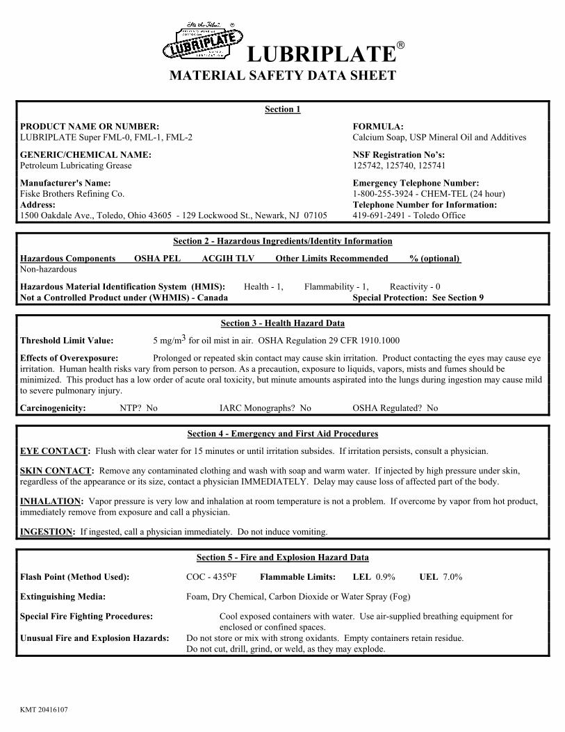
LUBRIPLATE
MATERIAL SAFETY DATA SHEET
Section 1
PRODUCT NAME OR NUMBER: FORMULA: LUBRIPLATE Super FML-0, FML-1, FML-2 Calcium Soap, USP Mineral Oil and Additives
GENERIC/CHEMICAL NAME: NSF Registration No’s: Petroleum Lubricating Grease 125742, 125740, 125741
Manufacturer's Name: Emergency Telephone Number: Fiske Brothers Refining Co. 1-800-255-3924 - CHEM-TEL (24 hour) Address: Telephone Number for Information: 1500 Oakdale Ave., Toledo, Ohio 43605 - 129 Lockwood St., Newark, NJ 07105 419-691-2491 - Toledo Office
Section 2 - Hazardous Ingredients/Identity Information
Hazardous Components OSHA PEL ACGIH TLV Other Limits Recommended % (optional) Non-hazardous
Hazardous Material Identification System (HMIS): Health - 1, Flammability - 1, Reactivity - 0 Not a Controlled Product under (WHMIS) - Canada Special Protection: See Section 9
Section 3 - Health Hazard Data
Threshold Limit Value: 5 mg/m3 for oil mist in air. OSHA Regulation 29 CFR 1910.1000
Effects of Overexposure: Prolonged or repeated skin contact may cause skin irritation. Product contacting the eyes may cause eye irritation. Human health risks vary from person to person. As a precaution, exposure to liquids, vapors, mists and fumes should be minimized. This product has a low order of acute oral toxicity, but minute amounts aspirated into the lungs during ingestion may cause mild to severe pulmonary injury.
Carcinogenicity: NTP? No IARC Monographs? No OSHA Regulated? No
Section 4 - Emergency and First Aid Procedures
EYE CONTACT: Flush with clear water for 15 minutes or until irritation subsides. If irritation persists, consult a physician. SKIN CONTACT: Remove any contaminated clothing and wash with soap and warm water. If injected by high pressure under skin, regardless of the appearance or its size, contact a physician IMMEDIATELY. Delay may cause loss of affected part of the body. INHALATION: Vapor pressure is very low and inhalation at room temperature is not a problem. If overcome by vapor from hot product, immediately remove from exposure and call a physician. INGESTION: If ingested, call a physician immediately. Do not induce vomiting.
Section 5 - Fire and Explosion Hazard Data Flash Point (Method Used): COC - 435oF Flammable Limits: LEL 0.9% UEL 7.0% Extinguishing Media: Foam, Dry Chemical, Carbon Dioxide or Water Spray (Fog) Special Fire Fighting Procedures: Cool exposed containers with water. Use air-supplied breathing equipment for enclosed or confined spaces. Unusual Fire and Explosion Hazards: Do not store or mix with strong oxidants. Empty containers retain residue. Do not cut, drill, grind, or weld, as they may explode.
KMT 20416107
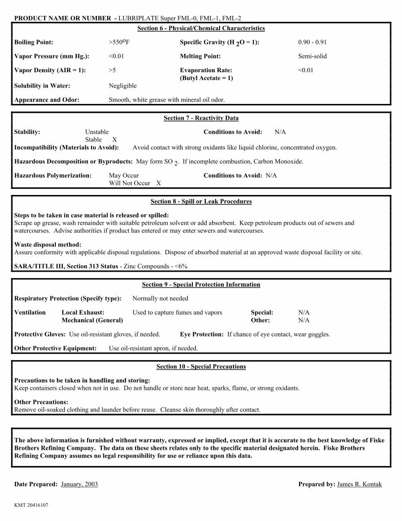
PRODUCT NAME OR NUMBER - LUBRIPLATE Super FML-0, FML-1, FML-2
Section 6 - Physical/Chemical Characteristics Boiling Point: >550oF Specific Gravity (H 2O = 1): 0.90 - 0.91 Vapor Pressure (mm Hg.): <0.01 Melting Point: Semi-solid Vapor Density (AIR = 1): >5 Evaporation Rate: <0.01 (Butyl Acetate = 1) Solubility in Water: Negligible Appearance and Odor: Smooth, white grease with mineral oil odor.
Section 7 - Reactivity Data
Stability: Unstable Conditions to Avoid: N/A Stable X Incompatibility (Materials to Avoid): Avoid contact with strong oxidants like liquid chlorine, concentrated oxygen. Hazardous Decomposition or Byproducts: May form SO 2. If incomplete combustion, Carbon Monoxide. Hazardous Polymerization: May Occur Conditions to Avoid: N/A Will Not Occur X
Section 8 - Spill or Leak Procedures Steps to be taken in case material is released or spilled: Scrape up grease, wash remainder with suitable petroleum solvent or add absorbent. Keep petroleum products out of sewers and watercourses. Advise authorities if product has entered or may enter sewers and watercourses. Waste disposal method: Assure conformity with applicable disposal regulations. Dispose of absorbed material at an approved waste disposal facility or site. SARA/TITLE III, Section 313 Status - Zinc Compounds - <6%
Section 9 - Special Protection Information Respiratory Protection (Specify type): Normally not needed Ventilation Local Exhaust: Used to capture fumes and vapors Special: N/A Mechanical (General) Other: N/A Protective Gloves: Use oil-resistant gloves, if needed. Eye Protection: If chance of eye contact, wear goggles. Other Protective Equipment: Use oil-resistant apron, if needed.
Section 10 - Special Precautions Precautions to be taken in handling and storing: Keep containers closed when not in use. Do not handle or store near heat, sparks, flame, or strong oxidants. Other Precautions: Remove oil-soaked clothing and launder before reuse. Cleanse skin thoroughly after contact. The above information is furnished without warranty, expressed or implied, except that it is accurate to the best knowledge of Fiske Brothers Refining Company. The data on these sheets relates only to the specific material designated herein. Fiske Brothers Refining Company assumes no legal responsibility for use or reliance upon this data. Date Prepared: January, 2003 Prepared by: James R. Kontak
KMT 20416107
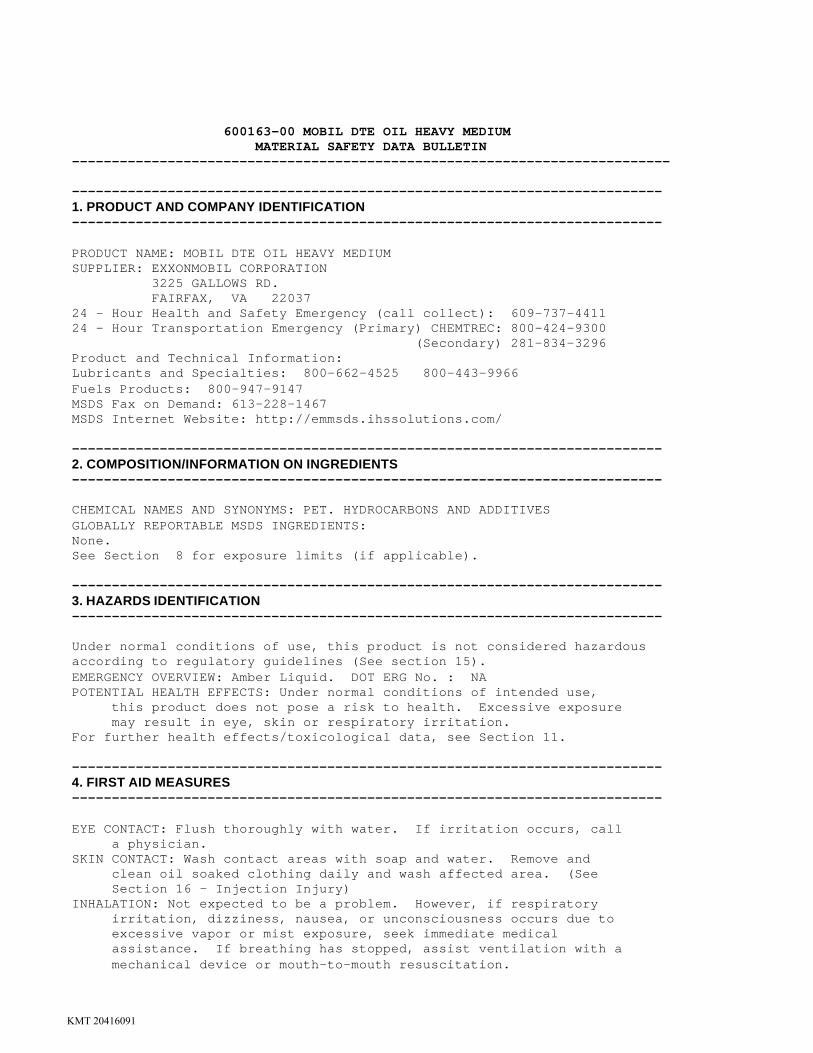
600163-00 MOBIL DTE OIL HEAVY MEDIUM MATERIAL SAFETY DATA BULLETIN --------------------------------------------------------------------------- -------------------------------------------------------------------------- 1. PRODUCT AND COMPANY IDENTIFICATION -------------------------------------------------------------------------- PRODUCT NAME: MOBIL DTE OIL HEAVY MEDIUM SUPPLIER: EXXONMOBIL CORPORATION 3225 GALLOWS RD. FAIRFAX, VA 22037 24 - Hour Health and Safety Emergency (call collect): 609-737-4411 24 - Hour Transportation Emergency (Primary) CHEMTREC: 800-424-9300 (Secondary) 281-834-3296 Product and Technical Information: Lubricants and Specialties: 800-662-4525 800-443-9966 Fuels Products: 800-947-9147 MSDS Fax on Demand: 613-228-1467 MSDS Internet Website: http://emmsds.ihssolutions.com/ -------------------------------------------------------------------------- 2. COMPOSITION/INFORMATION ON INGREDIENTS -------------------------------------------------------------------------- CHEMICAL NAMES AND SYNONYMS: PET. HYDROCARBONS AND ADDITIVES GLOBALLY REPORTABLE MSDS INGREDIENTS: None. See Section 8 for exposure limits (if applicable). -------------------------------------------------------------------------- 3. HAZARDS IDENTIFICATION -------------------------------------------------------------------------- Under normal conditions of use, this product is not considered hazardous according to regulatory guidelines (See section 15). EMERGENCY OVERVIEW: Amber Liquid. DOT ERG No. : NA POTENTIAL HEALTH EFFECTS: Under normal conditions of intended use, this product does not pose a risk to health. Excessive exposure may result in eye, skin or respiratory irritation. For further health effects/toxicological data, see Section 11. -------------------------------------------------------------------------- 4. FIRST AID MEASURES -------------------------------------------------------------------------- EYE CONTACT: Flush thoroughly with water. If irritation occurs, call a physician. SKIN CONTACT: Wash contact areas with soap and water. Remove and clean oil soaked clothing daily and wash affected area. (See Section 16 - Injection Injury) INHALATION: Not expected to be a problem. However, if respiratory irritation, dizziness, nausea, or unconsciousness occurs due to excessive vapor or mist exposure, seek immediate medical assistance. If breathing has stopped, assist ventilation with a mechanical device or mouth-to-mouth resuscitation.
KMT 20416091

INGESTION: Not expected to be a problem. Seek medical attention if discomfort occurs. Do not induce vomiting. -------------------------------------------------------------------------- 5. FIRE-FIGHTING MEASURES -------------------------------------------------------------------------- EXTINGUISHING MEDIA: Carbon dioxide, foam, dry chemical and water fog. SPECIAL FIRE FIGHTING PROCEDURES: Water or foam may cause frothing. Use water to keep fire exposed containers cool. Water spray may be used to flush spills away from exposure. Prevent runoff from fire control or dilution from entering streams, sewers, or drinking water supply. SPECIAL PROTECTIVE EQUIPMENT: For fires in enclosed areas, fire fighters must use self-contained breathing apparatus. UNUSUAL FIRE AND EXPLOSION HAZARDS: None. COMBUSTION PRODUCTS: Fumes, smoke, carbon monoxide, sulfur oxides, aldehydes and other decomposition products, in the case of incomplete combustion. Flash Point C(F): > 204(400) (ASTM D-93). Flammable Limits (approx.% vol.in air) - LEL: 0.9%, UEL: 7.0% NFPA HAZARD ID: Health: 0, Flammability: 1, Reactivity: 0 -------------------------------------------------------------------------- 6. ACCIDENTAL RELEASE MEASURES -------------------------------------------------------------------------- NOTIFICATION PROCEDURES: Report spills/releases as required to appropriate authorities. U.S. Coast Guard and EPA regulations require immediate reporting of spills/releases that could reach any waterway including intermittent dry creeks. Report spill/release to Coast Guard National Response Center toll free number (800)424-8802. In case of accident or road spill notify CHEMTREC (800) 424-9300. PROCEDURES IF MATERIAL IS RELEASED OR SPILLED: LAND SPILL: Shut off source taking normal safety precautions. Take measures to minimize the effects on ground water. Recover by pumping or contain spilled material with sand or other suitable absorbent and remove mechanically into containers. If necessary, dispose of adsorbed residues as directed in Section 13. WATER SPILL: Confine the spill immediately with booms. Warn other ships in the vicinity. Notify port and other relevant authorities. Remove from the surface by skimming or with suitable absorbents. If permitted by regulatory authorities the use of suitable dispersants should be considered where recommended in local oil spill procedures. ENVIRONMENTAL PRECAUTIONS: Prevent material from entering sewers, water sources or low lying areas; advise the relevant authorities if it has, or if it contaminates soil/vegetation. PERSONAL PRECAUTIONS: See Section 8 -------------------------------------------------------------------------- 7. HANDLING AND STORAGE -------------------------------------------------------------------------- HANDLING: No special precautions are necessary beyond normal good hygiene practices. See Section 8 for additional personal protection advice when handling this product. STORAGE: Keep containers closed when not in use. Do not store in open or unlabelled containers. Store away from strong oxidizing
KMT 20416091
agents and combustible materials. Do not store near heat, sparks, flame or strong oxidants. SPECIAL PRECAUTIONS: Prevent small spills and leakages to avoid slip hazard. EMPTY CONTAINER WARNING: Empty containers retain residue (liquid and/or vapor) and can be dangerous. DO NOT PRESSURIZE, CUT, WELD, BRAZE, SOLDER, DRILL, GRIND OR EXPOSE SUCH CONTAINERS TO HEAT, FLAME, SPARKS, STATIC ELECTRICITY, OR OTHER SOURCES OF IGNITION; THEY MAY EXPLODE AND CAUSE INJURY OR DEATH. Do not attempt to refill or clean container since residue is difficult to remove. Empty drums should be completely drained, properly bunged and promptly returned to a drum reconditioner. All containers should be disposed of in an environmentally safe manner and in accordance with governmental regulations. -------------------------------------------------------------------------- 8. EXPOSURE CONTROLS/PERSONAL PROTECTION -------------------------------------------------------------------------- OCCUPATIONAL EXPOSURE LIMITS: When mists/aerosols can occur, the following are recommended: 5 mg/m3 (as oil mist)- ACGIH Threshold Limit Value (TLV), 10 mg/m3 (as oil mist) - ACGIH Short Term Exposure Limit (STEL), 5 mg/m3 (as oil mist) - OSHA Permissible Exposure Limit (PEL) VENTILATION: If mists are generated, use adequate ventilation, local exhaust or enclosures to control below exposure limits. RESPIRATORY PROTECTION: If mists are generated, and/or when ventilation is not adequate, wear approved respirator. EYE PROTECTION: If eye contact is likely, safety glasses with side shields or chemical type goggles should be worn. SKIN PROTECTION: Not normally required. When splashing or liquid contact can occur frequently, wear oil resistant gloves and/or other protective clothing. Good personal hygiene practices should always be followed. -------------------------------------------------------------------------- 9. PHYSICAL AND CHEMICAL PROPERTIES -------------------------------------------------------------------------- Typical physical properties are given below. Consult Product Data Sheet for specific details. APPEARANCE: Liquid COLOR: Amber ODOR: Mild ODOR THRESHOLD-ppm: NE pH: NA BOILING POINT C(F): > 316(600) MELTING POINT C(F): NA FLASH POINT C(F): > 204(400) (ASTM D-93) FLAMMABILITY (solids): NE AUTO FLAMMABILITY C(F): NA EXPLOSIVE PROPERTIES: NA OXIDIZING PROPERTIES: NA VAPOR PRESSURE-mmHg 20 C: < 0.1 VAPOR DENSITY: > 2.0 EVAPORATION RATE: NE RELATIVE DENSITY, 15/4 C: 0.875 SOLUBILITY IN WATER: Negligible PARTITION COEFFICIENT: > 3.5 VISCOSITY AT 40 C, cSt: 68.0
KMT 20416091
VISCOSITY AT 100 C, cSt: 8.7 POUR POINT C(F): < -6(22) FREEZING POINT C(F): NE VOLATILE ORGANIC COMPOUND: NE DMSO EXTRACT, IP-346 (WT.%): <3, for mineral oil only NA=NOT APPLICABLE NE=NOT ESTABLISHED D=DECOMPOSES FOR FURTHER TECHNICAL INFORMATION, CONTACT YOUR MARKETING REPRESENTATIVE -------------------------------------------------------------------------- 10. STABILITY AND REACTIVITY -------------------------------------------------------------------------- STABILITY (THERMAL, LIGHT, ETC.): Stable. CONDITIONS TO AVOID: Extreme heat and high energy sources of ignition. INCOMPATIBILITY (MATERIALS TO AVOID): Strong oxidizers. HAZARDOUS DECOMPOSITION PRODUCTS: Product does not decompose at ambient temperatures. HAZARDOUS POLYMERIZATION: Will not occur. -------------------------------------------------------------------------- 11. TOXICOLOGICAL DATA -------------------------------------------------------------------------- ---ACUTE TOXICOLOGY--- ORAL TOXICITY (RATS): Practically non-toxic (LD50: greater than 2000 mg/kg). ---Based on testing of similar products and/or the components. DERMAL TOXICITY (RABBITS): Practically non-toxic (LD50: greater than 2000 mg/kg). ---Based on testing of similar products and/or the components. INHALATION TOXICITY (RATS): Practically non-toxic (LC50: greater than 5 mg/l). ---Based on testing of similar products and/or the components. EYE IRRITATION (RABBITS): Practically non-irritating. (Draize score: greater than 6 but 15 or less). ---Based on testing of similar products and/or the components. SKIN IRRITATION (RABBITS): Practically non-irritating. (Primary Irritation Index: greater than 0.5 but less than 3). ---Based on testing of similar products and/or the components. OTHER ACUTE TOXICITY DATA: Although an acute inhalation study was not performed with this product, a variety of mineral and synthetic oils, such as those in this product, have been tested. These samples had virtually no effect other than a nonspecific inflammatory response in the lung to the aerosolized mineral oil. The presence of additives in other tested formulations (in approximately the same amounts as in the present formulation) did not alter the observed effects. ---SUBCHRONIC TOXICOLOGY (SUMMARY)--- No significant adverse effects were found in studies using repeated dermal applications of similar formulations to the skin of laboratory animals for 13 weeks at doses significantly higher than those expected during normal industrial exposure. The animals were evaluated extensively for effects of exposure (hematology, serum chemistry, urinalysis, organ weights, microscopic examination of tissues etc.). ---REPRODUCTIVE TOXICOLOGY (SUMMARY)--- No teratogenic effects would be expected from dermal exposure, based on laboratory developmental toxicity studies of major components in this formulation and/or materials of similar composition. ---CHRONIC TOXICOLOGY (SUMMARY)---
KMT 20416091
Repeated and/or prolonged exposure may cause irritation to the skin, eyes or respiratory tract. Overexposure to oil mist may result in oil droplet deposition and/or granuloma formation. For mineral base oils: Base oils in this product are severely solvent refined and/or severely hydrotreated. Chronic mouse skin painting studies of severely treated oils showed no evidence of carcinogenic effects. These results are confirmed on a continuing basis using various screening methods such as Modified Ames Test, IP-346, and/or other analytical methods. For synthetic base oils: The base oils in this product have been tested in the Ames assay and other tests of mutagenicity with negative results. These base oils are not expected to be carcinogenic with chronic dermal exposures. ---SENSITIZATION (SUMMARY)--- Not expected to be sensitizing based on tests of this product, components, or similar products. -------------------------------------------------------------------------- 12. ECOLOGICAL INFORMATION -------------------------------------------------------------------------- ENVIRONMENTAL FATE AND EFFECTS: In the absence of specific environmental data for this product, this assessment is based on information for representative products. ECOTOXICITY: Available ectoxicity data (LL50 >1000 mg/L) indicates that adverse effects to aquatic organisms are not expected from this product. MOBILITY: When released into the environment, adsorption to sediment and soil will be the predominant behavior. PERSISTENCE AND DEGRADABILITY: This product is expected to be inherently biodegradable. BIOACCUMULATIVE POTENTIAL: Bioaccumulation is unlikely due to the very low water solubility of this product, therefore bioavailability to aquatic organisms is minimal. -------------------------------------------------------------------------- 13. DISPOSAL CONSIDERATIONS -------------------------------------------------------------------------- WASTE DISPOSAL: Product is suitable for burning in an enclosed, controlled burner for fuel value. Such burning may be limited pursuant to the Resource Conservation and Recovery Act. In addition, the product is suitable for processing by an approved recycling facility or can be disposed of at an appropriate government waste disposal facility. Use of these methods is subject to user compliance with applicable laws and regulations and consideration of product characteristics at time of disposal. RCRA INFORMATION: The unused product, in our opinion, is not specifically listed by the EPA as a hazardous waste (40 CFR, Part 261D), nor is it formulated to contain materials which are listed hazardous wastes. It does not exhibit the hazardous characteristics of ignitability, corrosivity, or reactivity. The unused product is not formulated with substances covered by the Toxicity Characteristic Leaching Procedure (TCLP). However, used product may be regulated. -------------------------------------------------------------------------- 14. TRANSPORT INFORMATION --------------------------------------------------------------------------
KMT 20416091

USA DOT: NOT REGULATED BY USA DOT. RID/ADR: NOT REGULATED BY RID/ADR. IMO: NOT REGULATED BY IMO. IATA: NOT REGULATED BY IATA. STATIC ACCUMULATOR (50 picosiemens or less): YES -------------------------------------------------------------------------- 15. REGULATORY INFORMATION -------------------------------------------------------------------------- US OSHA HAZARD COMMUNICATION STANDARD: When used for its intended purposes, this product is not classified as hazardous in accordance with OSHA 29 CFR 1910.1200. EU Labeling: Product is not dangerous as defined by the European Union Dangerous Substances/Preparations Directives. EU labeling not required. Governmental Inventory Status: All components comply with TSCA, EINECS/ELINCS, AICS, and DSL. U.S. Superfund Amendments and Reauthorization Act (SARA) Title III: This product contains no "EXTREMELY HAZARDOUS SUBSTANCES". SARA (311/312) REPORTABLE HAZARD CATEGORIES: None. This product contains no chemicals subject to the supplier notification requirements of SARA (313) toxic release program. THIS PRODUCT HAS BEEN AUTHORIZED BY USDA FOR USE UNDER THE FOLLOWING CATEGORY: This product is acceptable as a lubricant where there is no possibility of food contact (complies with earlier USDA guidelines for H-2 lubricant use). The following product ingredients are cited on the lists below: CHEMICAL NAME CAS NUMBER LIST CITATIONS ------------- ---------- -------------- ZINC (ELEMENTAL ANALYSIS) (<0.01%) 7440-66-6 22 PHOSPHORODITHOIC ACID, O,O-DI 68649-42-3 22 C1-14-ALKYL ESTERS, ZINC SALTS (2: 1) (ZDDP) (0.09%) --- REGULATORY LISTS SEARCHED --- 1=ACGIH ALL 6=IARC 1 11=TSCA 4 16=CA P65 CARC 21=LA RTK 2=ACGIH A1 7=IARC 2A 12=TSCA 5a2 17=CA P65 REPRO 22=MI 293 3=ACGIH A2 8=IARC 2B 13=TSCA 5e 18=CA RTK 23=MN RTK 4=NTP CARC 9=OSHA CARC 14=TSCA 6 19=FL RTK 24=NJ RTK 5=NTP SUS 10=OSHA Z 15=TSCA 12b 20=IL RTK 25=PA RTK 26=RI RTK Code key: CARC=Carcinogen; SUS=Suspected Carcinogen; REPRO=Reproductive -------------------------------------------------------------------------- 16. OTHER INFORMATION -------------------------------------------------------------------------- USE: STEAM TURBINE OIL NOTE: PRODUCTS OF EXXON MOBIL CORPORATION AND ITS AFFILIATED COMPANIES ARE NOT FORMULATED TO CONTAIN PCBS. Health studies have shown that many hydrocarbons pose potential human health risks which may vary from person to person. Information provided on this MSDS reflects intended use. This product should not be used for other applications. In any case, the following advice should be considered: INJECTION INJURY WARNING: If product is injected into or under the skin, or into any part of the body, regardless of the appearance of the wound or its size, the individual should be evaluated immediately by a physician as a surgical emergency. Even though initial symptoms from high pressure injection may be minimal or absent, early surgical
KMT 20416091

treatment within the first few hours may significantly reduce the ultimate extent of injury. INDUSTRIAL LABEL Under normal conditions of intended use, this product does not pose a risk to health. Excessive exposure may result in eye, skin or respiratory irritation. Always observe good hygiene measures. First Aid: Wash skin with soap and water. Flush eyes with water. If overcome by fumes or vapor, remove to fresh air. If ingested do not induce vomiting. If symptoms persist seek medical assistance. Read and understand the MSDS before using this product. ************************************************************************* For Internal Use Only: MHC: 1* 1* 1* 1* 1*, MPPEC: A, TRN: 600163-00, ELIS: 400304, CMCS97: 970172, REQ: US - MARKETING, SAFE USE: L EHS Approval Date: 21AUG2001 ************************************************************************* ************************************************************************* Legally required information is given in accordance with applicable Information given herein is offered in good faith as accurate, but without guarantee. Conditions of use and suitability of the product for particular uses are beyond our control; all risks of use of the product are therefore assumed by the user and WE EXPRESSLY DISCLAIM ALL WARRANTIES OF EVERY KIND AND NATURE, INCLUDING WARRANTIES OF MERCHANTABILITY AND FITNESS FOR A PARTICULAR PURPOSE IN RESPECT TO THE USE OR SUITABILITY OF THE PRODUCT. Nothing is intended as a recommendation for uses which infringe valid patents or as extending any license under valid patents. Appropiate warnings and safe handling procedures should be providedto handlers and users. Use or re- transmission of the information contained herein in any other format than the format as presented is strictly prohibited. ExxonMobil neither represents nor warrants that the format, content or product formulas contained in this document comply with the laws of any other country except the United States of America. ************************************************************************* Copyright 2001 Exxon Mobil Corporation, All rights reserved
KMT 20416091

Material Safety Data Sheet
HYDROCLEAR MULTIPURPOSE R&O OIL 32, 46, 68, 100, 150, 220, 320, 460
---------------------------------------------------------------------------��# 1. CHEMICAL PRODUCT/COMPANY IDENTIFICATION��---------------------------------------------------------------------------���� HYDROCLEAR(R) MULTIPURPOSE R&O OIL �� �� MSDS Code: HYDC0009 Revised: 29-July-2002 ���� "HYDROCLEAR" is a registered trademark of Conoco. �� �� ISO Grades: 32, 46, 68 100, 150, 220, 320, 460 �� Product Use: Industrial Oil ���� MANUFACTURER/DISTRIBUTOR �� Conoco Inc. �� PO Box 2197 �� Houston, TX 77252 �� �� PHONE NUMBERS �� Product Information: 1-281-293-5550 �� Transport Emergency: CHEMTREC 1-800-424-9300 or�� 1-703-527-3887 (call collect)�� Medical Emergency: 1-800-342-5119 or 1-281-293-5119�� WEB SITE: www.conoco.com��---------------------------------------------------------------------------��# 2. COMPOSITION/INFORMATION ON INGREDIENTS ��---------------------------------------------------------------------------�� COMPONENTS CAS NUMBER % �� Highly refined base oils 64742-54-7 0-99.5�� 64742-01-4 0-99.5 �� Proprietary additives <5 �� �� If oil mist is generated, exposure limits apply. See Section 8.��---------------------------------------------------------------------------��# 3. HAZARDS IDENTIFICATION ��---------------------------------------------------------------------------�� �� --- EMERGENCY OVERVIEW ---�� APPEARANCE / ODOR�� Clear and bright liquid / mild petroleum hydrocarbon odor.���� OSHA REGULATORY STATUS�� This material is classified as non-hazardous under OSHA Regulations.���� HMIS RATING Health: 1; Flammability: 1; Physical Hazard: 0.�� NFPA RATING Health: 1; Flammability: 1; Instability: 0.�� ___________________________________���� Potential Health Effects �� Primary Route of Entry: Skin �� �
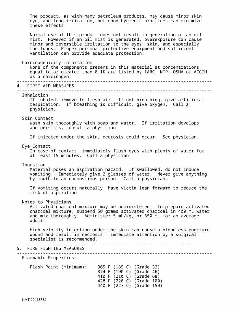
� The product, as with many petroleum products, may cause minor skin, �� eye, and lung irritation, but good hygienic practices can minimize �� these effects. �� �� Normal use of this product does not result in generation of an oil �� mist. However if an oil mist is generated, overexposure can cause �� minor and reversible irritation to the eyes, skin, and especially �� the lungs. Proper personal protective equipment and sufficient �� ventilation can provide adequate protection. �� �� Carcinogenicity Information �� None of the components present in this material at concentrations �� equal to or greater than 0.1% are listed by IARC, NTP, OSHA or ACGIH �� as a carcinogen. ��---------------------------------------------------------------------------��4. FIRST AID MEASURES ��---------------------------------------------------------------------------�� Inhalation �� If inhaled, remove to fresh air. If not breathing, give artificial �� respiration. If breathing is difficult, give oxygen. Call a �� physician. �� �� Skin Contact �� Wash skin thoroughly with soap and water. If irritation develops �� and persists, consult a physician. �� �� If injected under the skin, necrosis could occur. See physician. �� �� Eye Contact �� In case of contact, immediately flush eyes with plenty of water for �� at least 15 minutes. Call a physician. �� �� Ingestion �� Material poses an aspiration hazard. If swallowed, do not induce �� vomiting. Immediately give 2 glasses of water. Never give anything �� by mouth to an unconscious person. Call a physician. �� �� If vomiting occurs naturally, have victim lean forward to reduce the �� risk of aspiration. �� �� Notes to Physicians �� Activated charcoal mixture may be administered. To prepare activated �� charcoal mixture, suspend 50 grams activated charcoal in 400 mL water �� and mix thoroughly. Administer 5 mL/kg, or 350 mL for an average �� adult. �� �� High velocity injection under the skin can cause a bloodless puncture �� wound and result in necrosis. Immediate attention by a surgical �� specialist is recommended. ��---------------------------------------------------------------------------��5. FIRE FIGHTING MEASURES ��---------------------------------------------------------------------------�� Flammable Properties �� �� Flash Point (minimum): 365 F (185 C) (Grade 32) �� 374 F (190 C) (Grade 46) �� 410 F (210 C) (Grade 68) �� 428 F (220 C) (Grade 100) �� 440 F (227 C) (Grade 150) �

� 460 F (238 C) (Grade 220) �� 490 F (254 C) (Grade 320) �� 509 F (265 C) (Grade 460) �� �� Flash Point (typical): 450 F (232 C) (Grade 32) �� 460 F (238 C) (Grade 46) �� 470 F (243 C) (Grade 68) �� 515 F (268 C) (Grade 100) �� 530 F (277 C) (Grade 150) �� 545 F (285 C) (Grade 220) �� 580 F (304 C) (Grade 320) �� 585 F (307 C) (Grade 460) �� �� Method: COC �� Autoignition: Not Available �� Flammable limits in Air, % by Volume �� LEL: Undetermined �� UEL: Undetermined �� �� Extinguishing Media �� Water Spray, Foam, Dry Chemical, CO2. �� �� Fire Fighting Instructions �� Water or foam may cause frothing. Use water to keep fire-exposed �� containers cool. Water may be used to flush spills away from �� exposures. �� �� Products of combustion may contain carbon monoxide, carbon dioxide, �� and other toxic materials. Do not enter enclosed or confined space �� without proper protective equipment including respiratory protection. ��---------------------------------------------------------------------------��6. ACCIDENTAL RELEASE MEASURES ��---------------------------------------------------------------------------�� Safeguards (Personnel) �� NOTE: Review FIRE FIGHTING MEASURES and HANDLING (PERSONNEL) sections �� before proceeding with clean-up. Use appropriate PERSONAL PROTECTIVE �� EQUIPMENT during clean-up. �� �� Remove source of heat, sparks, and flame. �� �� Initial Containment �� Dike spill. Prevent material from entering sewers, waterways, or �� low areas. �� �� Spill Clean Up �� Recover free liquid for reuse or reclamation. Soak up with sawdust, �� sand, oil dry or other absorbent material. ��---------------------------------------------------------------------------��7. HANDLING AND STORAGE ��---------------------------------------------------------------------------��Handling (Personnel) �� Avoid breathing vapors or mist. Avoid contact with eyes. Avoid �� prolonged or repeated contact with skin. Wash thoroughly after �� handling. Wash contaminated clothing prior to reuse. �� �� Handling (Physical Aspects) �� Close container after each use. Do not pressurize, cut, weld, braze, �� solder, grind, or drill on or near full or empty container. Empty �� container retains residue (liquid and/or vapor) and may explode in �
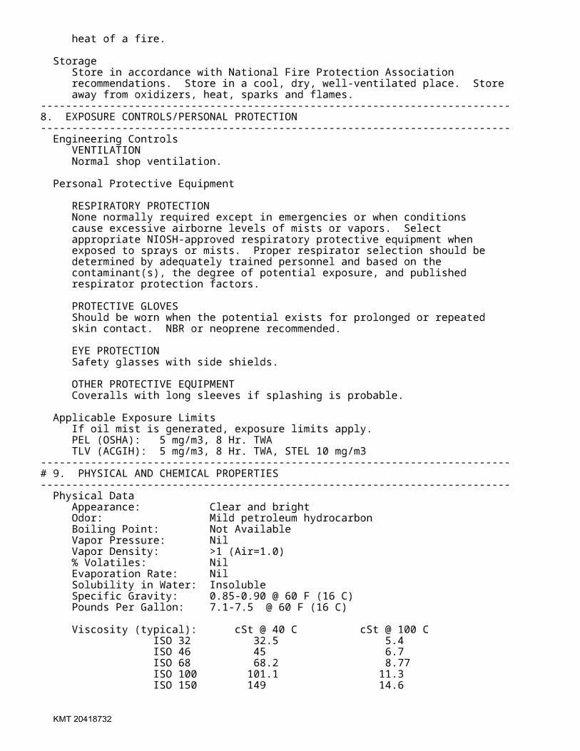
� heat of a fire. �� �� Storage �� Store in accordance with National Fire Protection Association �� recommendations. Store in a cool, dry, well-ventilated place. Store �� away from oxidizers, heat, sparks and flames. ��---------------------------------------------------------------------------��8. EXPOSURE CONTROLS/PERSONAL PROTECTION ��---------------------------------------------------------------------------�� Engineering Controls �� VENTILATION �� Normal shop ventilation. �� �� Personal Protective Equipment �� �� RESPIRATORY PROTECTION �� None normally required except in emergencies or when conditions �� cause excessive airborne levels of mists or vapors. Select �� appropriate NIOSH-approved respiratory protective equipment when �� exposed to sprays or mists. Proper respirator selection should be �� determined by adequately trained personnel and based on the �� contaminant(s), the degree of potential exposure, and published �� respirator protection factors. �� �� PROTECTIVE GLOVES �� Should be worn when the potential exists for prolonged or repeated �� skin contact. NBR or neoprene recommended. �� �� EYE PROTECTION �� Safety glasses with side shields. �� �� OTHER PROTECTIVE EQUIPMENT �� Coveralls with long sleeves if splashing is probable. ���� Applicable Exposure Limits �� If oil mist is generated, exposure limits apply. �� PEL (OSHA): 5 mg/m3, 8 Hr. TWA �� TLV (ACGIH): 5 mg/m3, 8 Hr. TWA, STEL 10 mg/m3 ��---------------------------------------------------------------------------��# 9. PHYSICAL AND CHEMICAL PROPERTIES ��---------------------------------------------------------------------------�� Physical Data �� Appearance: Clear and bright�� Odor: Mild petroleum hydrocarbon�� Boiling Point: Not Available �� Vapor Pressure: Nil �� Vapor Density: >1 (Air=1.0) �� % Volatiles: Nil �� Evaporation Rate: Nil �� Solubility in Water: Insoluble �� Specific Gravity: 0.85-0.90 @ 60 F (16 C) �� Pounds Per Gallon: 7.1-7.5 @ 60 F (16 C) ���� Viscosity (typical): cSt @ 40 C cSt @ 100 C �� ISO 32 32.5 5.4�� ISO 46 45 6.7�� ISO 68 68.2 8.77�� ISO 100 101.1 11.3 �� ISO 150 149 14.6�

� ISO 320 318 23.9�� ISO 460 464 30.6��---------------------------------------------------------------------------��10. STABILITY AND REACTIVITY ��---------------------------------------------------------------------------�� Chemical Stability �� Stable at normal temperatures and storage conditions. �� �� Conditions to Avoid �� Heat, sparks, and flames. �� �� Incompatibility with Other Materials �� Incompatible or can react with strong oxidizers. �� �� Decomposition �� Normal combustion forms carbon dioxide; incomplete combustion may �� produce carbon monoxide. �� �� Polymerization �� Polymerization will not occur. ��---------------------------------------------------------------------------��11. TOXICOLOGICAL INFORMATION ��---------------------------------------------------------------------------�� Animal Data �� Mouse skin painting studies have shown that highly refined petroleum �� lube base oils similar to ingredients in this product have not caused �� skin tumors. ��---------------------------------------------------------------------------��12. ECOLOGICAL INFORMATION ��---------------------------------------------------------------------------�� Ecotoxicological Information �� No specific aquatic data available for this product. ��---------------------------------------------------------------------------��13. DISPOSAL CONSIDERATIONS ��---------------------------------------------------------------------------�� Waste Disposal �� Treatment, storage, transportation, and disposal must be in �� accordance with applicable Federal, State/Provincial, and Local �� regulations. Do not flush to surface water or sanitary sewer system. �� �� Container Disposal �� Empty drums should be completely drained, properly bunged, and �� promptly shipped to the supplier or a drum reconditioner. All other �� containers should be disposed of in an environmentally safe manner. ��---------------------------------------------------------------------------��14. TRANSPORTATION INFORMATION ��---------------------------------------------------------------------------�� Shipping Information �� DOT: Not regulated. �� IATA/IMDG: Not restricted. �� �� Canada: Not regulated. ��---------------------------------------------------------------------------��15. REGULATORY INFORMATION ��---------------------------------------------------------------------------�� U.S. Federal Regulations �� OSHA HAZARD DETERMINATION �� This material is not known to be hazardous as defined by OSHA's �� Hazard Communication Standard, 29 CFR 1910.1200. �
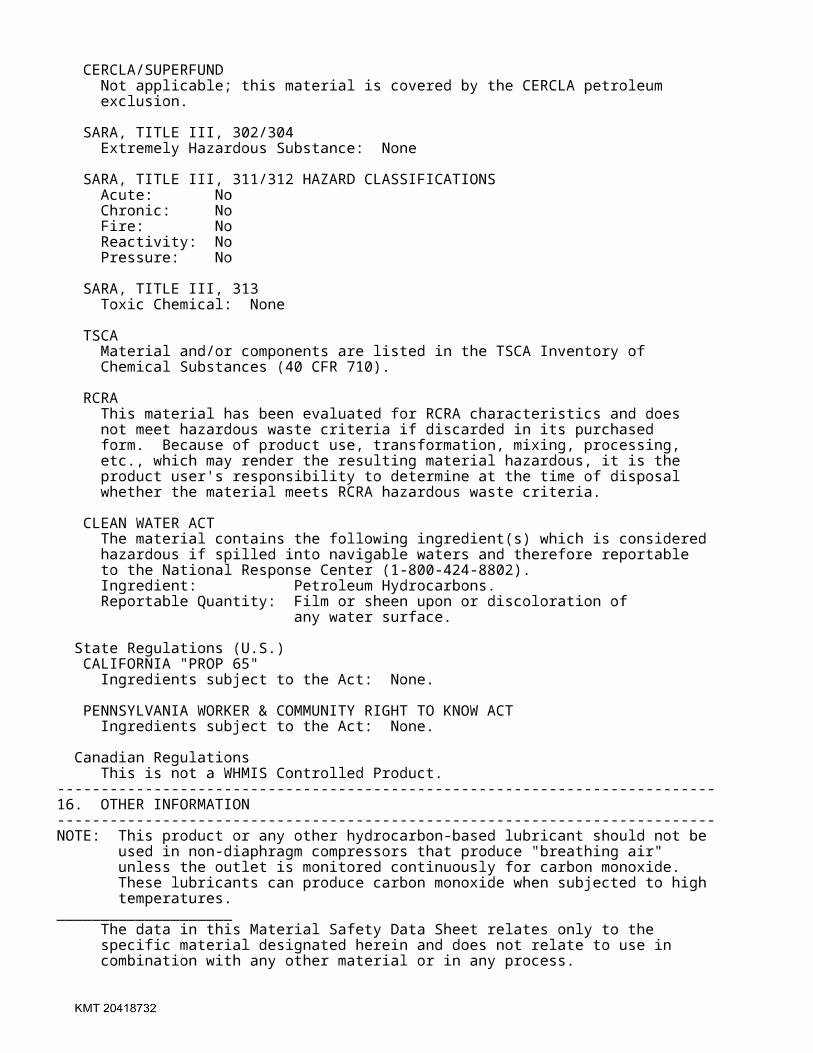
� �� CERCLA/SUPERFUND �� Not applicable; this material is covered by the CERCLA petroleum �� exclusion. �� �� SARA, TITLE III, 302/304 �� Extremely Hazardous Substance: None �� �� SARA, TITLE III, 311/312 HAZARD CLASSIFICATIONS �� Acute: No �� Chronic: No �� Fire: No �� Reactivity: No �� Pressure: No �� �� SARA, TITLE III, 313 �� Toxic Chemical: None �� �� TSCA �� Material and/or components are listed in the TSCA Inventory of �� Chemical Substances (40 CFR 710). �� �� RCRA �� This material has been evaluated for RCRA characteristics and does �� not meet hazardous waste criteria if discarded in its purchased �� form. Because of product use, transformation, mixing, processing, �� etc., which may render the resulting material hazardous, it is the �� product user's responsibility to determine at the time of disposal �� whether the material meets RCRA hazardous waste criteria. �� �� CLEAN WATER ACT �� The material contains the following ingredient(s) which is considered �� hazardous if spilled into navigable waters and therefore reportable �� to the National Response Center (1-800-424-8802). �� Ingredient: Petroleum Hydrocarbons. �� Reportable Quantity: Film or sheen upon or discoloration of �� any water surface. �� �� State Regulations (U.S.) �� CALIFORNIA "PROP 65" �� Ingredients subject to the Act: None. �� �� PENNSYLVANIA WORKER & COMMUNITY RIGHT TO KNOW ACT �� Ingredients subject to the Act: None. �� �� Canadian Regulations �� This is not a WHMIS Controlled Product. ��---------------------------------------------------------------------------��16. OTHER INFORMATION ��---------------------------------------------------------------------------��NOTE: This product or any other hydrocarbon-based lubricant should not be�� used in non-diaphragm compressors that produce "breathing air" �� unless the outlet is monitored continuously for carbon monoxide. �� These lubricants can produce carbon monoxide when subjected to high �� temperatures.��____________________�� The data in this Material Safety Data Sheet relates only to the �� specific material designated herein and does not relate to use in �� combination with any other material or in any process. �
� �� Responsibility for MSDS: DNA - SHE �� Address: Conoco Inc. �� PO Box 2197 �� Houston, TX 77252 �� Telephone: 1-281-293-5550 �� Web Site: www.conoco.com�� �� # Indicates updated section. �� End of MSDS �����