km front page - maintenance manual
TRANSCRIPT

EM 2000Multibeam echo sounder
Maintenance Manual

852-164378
EM 2000Multibeam echo sounder
Maintenance manual

About this document
Rev Date Written by Checked by Approved by
D 26.01.06 ASM IHRS GFS
General update: Technical specifications, cable layout, Operator stationand Processing unit. Datagram formats are removed, see own document.
© 2006 Kongsberg Maritime AS. All rights reserved.No part of this work covered by the copyright hereon may be reproduced or otherwisecopied without prior permission from Kongsberg Maritime AS.The information contained in this document is subject to change without prior notice.Kongsberg Maritime AS shall not be liable for errors contained herein, or for incidentalor consequential damages in connection with the furnishing, performance, or use of thisdocument.
Strandpromenaden 50P.O.Box 111N-3191 Horten,Norway
Maintenance manual
I852-164378 / D
Remarks
ReferencesFurther information about the EM 2000 system supplied to Base version may be foundin the following manuals:• EM 2000 Operator Manual• EM 2000 Installation Manual
The readerThis maintenance manual is intended to be used by a trained maintenance technician orengineer, with experience of electronic and digital circuitry, computers andelectromechanical design. The level of information is based on the maintenancephilosophy of Kongsberg Maritime: The onboard technical personnel shall, with thehelp of the documentation and the system’s built-in test functions, be able to identifymalfunctions, locate the fault, and replace major parts, modules and components on the“Line Replaceable Unit” (LRU) level. He/she will however not attempt to repair theLRUs.
EM 2000 / Base version
II 852-164378 / D
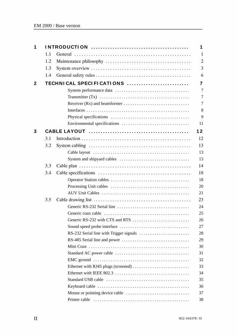
1 INTRODUCTION 1. . . . . . . . . . . . . . . . . . . . . . . . . . . . . . . . . . . . . . . . .1.1 General 1. . . . . . . . . . . . . . . . . . . . . . . . . . . . . . . . . . . . . . . . . . . . . . . . .
1.2 Maintenance philosophy 2. . . . . . . . . . . . . . . . . . . . . . . . . . . . . . . . . . . .
1.3 System overview 3. . . . . . . . . . . . . . . . . . . . . . . . . . . . . . . . . . . . . . . . . .
1.4 General safety rules 6. . . . . . . . . . . . . . . . . . . . . . . . . . . . . . . . . . . . . . . .
2 TECHNICAL SPECIFICATIONS 7. . . . . . . . . . . . . . . . . . . . . . . . . .System performance data 7. . . . . . . . . . . . . . . . . . . . . . . . . . . . . . . . . .Transmitter (Tx) 7. . . . . . . . . . . . . . . . . . . . . . . . . . . . . . . . . . . . . . . . .Receiver (Rx) and beamformer 7. . . . . . . . . . . . . . . . . . . . . . . . . . . . . .Interfaces 8. . . . . . . . . . . . . . . . . . . . . . . . . . . . . . . . . . . . . . . . . . . . . . .Physical specifications 9. . . . . . . . . . . . . . . . . . . . . . . . . . . . . . . . . . . .Environmental specifications 11. . . . . . . . . . . . . . . . . . . . . . . . . . . . . . .
3 CABLE LAYOUT 12. . . . . . . . . . . . . . . . . . . . . . . . . . . . . . . . . . . . . . . . . .3.1 Introduction 12. . . . . . . . . . . . . . . . . . . . . . . . . . . . . . . . . . . . . . . . . . . . . .
3.2 System cabling 13. . . . . . . . . . . . . . . . . . . . . . . . . . . . . . . . . . . . . . . . . . .
Cable layout 13. . . . . . . . . . . . . . . . . . . . . . . . . . . . . . . . . . . . . . . . . . . .System and shipyard cables 13. . . . . . . . . . . . . . . . . . . . . . . . . . . . . . . .
3.3 Cable plan 14. . . . . . . . . . . . . . . . . . . . . . . . . . . . . . . . . . . . . . . . . . . . . . .
3.4 Cable specifications 18. . . . . . . . . . . . . . . . . . . . . . . . . . . . . . . . . . . . . . .
Operator Station cables 18. . . . . . . . . . . . . . . . . . . . . . . . . . . . . . . . . . . .Processing Unit cables 20. . . . . . . . . . . . . . . . . . . . . . . . . . . . . . . . . . . .AUV Unit Cables 21. . . . . . . . . . . . . . . . . . . . . . . . . . . . . . . . . . . . . . . .
3.5 Cable drawing list 23. . . . . . . . . . . . . . . . . . . . . . . . . . . . . . . . . . . . . . . . .
Generic RS-232 Serial line 24. . . . . . . . . . . . . . . . . . . . . . . . . . . . . . . . .Generic coax cable 25. . . . . . . . . . . . . . . . . . . . . . . . . . . . . . . . . . . . . . .Generic RS-232 with CTS and RTS 26. . . . . . . . . . . . . . . . . . . . . . . . . .Sound speed probe interface 27. . . . . . . . . . . . . . . . . . . . . . . . . . . . . . . .RS-232 Serial line with Trigger signals 28. . . . . . . . . . . . . . . . . . . . . . .RS-485 Serial line and power 29. . . . . . . . . . . . . . . . . . . . . . . . . . . . . . .Mini Coax 30. . . . . . . . . . . . . . . . . . . . . . . . . . . . . . . . . . . . . . . . . . . . . .Standard AC power cable 31. . . . . . . . . . . . . . . . . . . . . . . . . . . . . . . . . .EMC ground 32. . . . . . . . . . . . . . . . . . . . . . . . . . . . . . . . . . . . . . . . . . . .Ethernet with RJ45 plugs (screened) 33. . . . . . . . . . . . . . . . . . . . . . . . . .Ethernet with IEEE 802.3 34. . . . . . . . . . . . . . . . . . . . . . . . . . . . . . . . . .Standard USB cable 35. . . . . . . . . . . . . . . . . . . . . . . . . . . . . . . . . . . . . .Keyboard cable 36. . . . . . . . . . . . . . . . . . . . . . . . . . . . . . . . . . . . . . . . . .Mouse or pointing device cable 37. . . . . . . . . . . . . . . . . . . . . . . . . . . . .Printer cable 38. . . . . . . . . . . . . . . . . . . . . . . . . . . . . . . . . . . . . . . . . . . .

Maintenance manual
III852-164378 / D
Digital Video Interface (DVI) display cable 39. . . . . . . . . . . . . . . . . . . .W600 - Remote synchronization 40. . . . . . . . . . . . . . . . . . . . . . . . . . . . .W807 - Sonar Head cable 41. . . . . . . . . . . . . . . . . . . . . . . . . . . . . . . . . .
3.6 Sonar Head cable drawings 42. . . . . . . . . . . . . . . . . . . . . . . . . . . . . . . . . .Standard Sonar Head cable 43. . . . . . . . . . . . . . . . . . . . . . . . . . . . . . . . .AUV Sonar Head cable 44. . . . . . . . . . . . . . . . . . . . . . . . . . . . . . . . . . . .
3.7 Sonar Head Connection 45. . . . . . . . . . . . . . . . . . . . . . . . . . . . . . . . . . . .Sonar Head cable 45. . . . . . . . . . . . . . . . . . . . . . . . . . . . . . . . . . . . . . . . .Internal wiring inside the bottle 45. . . . . . . . . . . . . . . . . . . . . . . . . . . . .
3.8 Basic cabling requirements 46. . . . . . . . . . . . . . . . . . . . . . . . . . . . . . . . . .
4 OPERATOR STATION 49. . . . . . . . . . . . . . . . . . . . . . . . . . . . . . . . . . . .4.1 Description and main functions 49. . . . . . . . . . . . . . . . . . . . . . . . . . . . . .
Introduction 49. . . . . . . . . . . . . . . . . . . . . . . . . . . . . . . . . . . . . . . . . . . . .4.2 Theory 51. . . . . . . . . . . . . . . . . . . . . . . . . . . . . . . . . . . . . . . . . . . . . . . . . .
Overview 51. . . . . . . . . . . . . . . . . . . . . . . . . . . . . . . . . . . . . . . . . . . . . . .Software 51. . . . . . . . . . . . . . . . . . . . . . . . . . . . . . . . . . . . . . . . . . . . . . .Data storage 51. . . . . . . . . . . . . . . . . . . . . . . . . . . . . . . . . . . . . . . . . . . . .
4.3 Installation 52. . . . . . . . . . . . . . . . . . . . . . . . . . . . . . . . . . . . . . . . . . . . . . .
5 PROCESSING UNIT 53. . . . . . . . . . . . . . . . . . . . . . . . . . . . . . . . . . . . . .5.1 Introduction 53. . . . . . . . . . . . . . . . . . . . . . . . . . . . . . . . . . . . . . . . . . . . . .
5.2 Standard Processing Unit drawing 54. . . . . . . . . . . . . . . . . . . . . . . . . . . .
5.3 AUV Processing Unit drawing 55. . . . . . . . . . . . . . . . . . . . . . . . . . . . . . .Circuit boards and modules 56. . . . . . . . . . . . . . . . . . . . . . . . . . . . . . . . .AUV Processing UnitCircuit boards and modules 57. . . . . . . . . . . . . . . . . . . . . . . . . . . . . . . . .
5.4 Theory of operation 59. . . . . . . . . . . . . . . . . . . . . . . . . . . . . . . . . . . . . . .Overview 59. . . . . . . . . . . . . . . . . . . . . . . . . . . . . . . . . . . . . . . . . . . . . . .Simplified block diagram 59. . . . . . . . . . . . . . . . . . . . . . . . . . . . . . . . . .Control functions 59. . . . . . . . . . . . . . . . . . . . . . . . . . . . . . . . . . . . . . . . .
5.5 Standard Processing Unit details 63. . . . . . . . . . . . . . . . . . . . . . . . . . . . .Circuit boards and modules 63. . . . . . . . . . . . . . . . . . . . . . . . . . . . . . . . .
5.6 AUV Processing Unit details 64. . . . . . . . . . . . . . . . . . . . . . . . . . . . . . . .
5.7 Circuit board descriptions 65. . . . . . . . . . . . . . . . . . . . . . . . . . . . . . . . . . .Overview 65. . . . . . . . . . . . . . . . . . . . . . . . . . . . . . . . . . . . . . . . . . . . . . .Serial Line Board (CI-104JS) 66. . . . . . . . . . . . . . . . . . . . . . . . . . . . . . .4-Ports Serial Line Board (C114P) 68. . . . . . . . . . . . . . . . . . . . . . . . . . .VIPer 629 Control Processor Board 70. . . . . . . . . . . . . . . . . . . . . . . . . .Cool Monster C3/400 Control Processor Board for AUV 71. . . . . . . . .Beamformer & Signal Processor (BSP) 73. . . . . . . . . . . . . . . . . . . . . . .
EM 2000 / Base version
IV 852-164378 / D
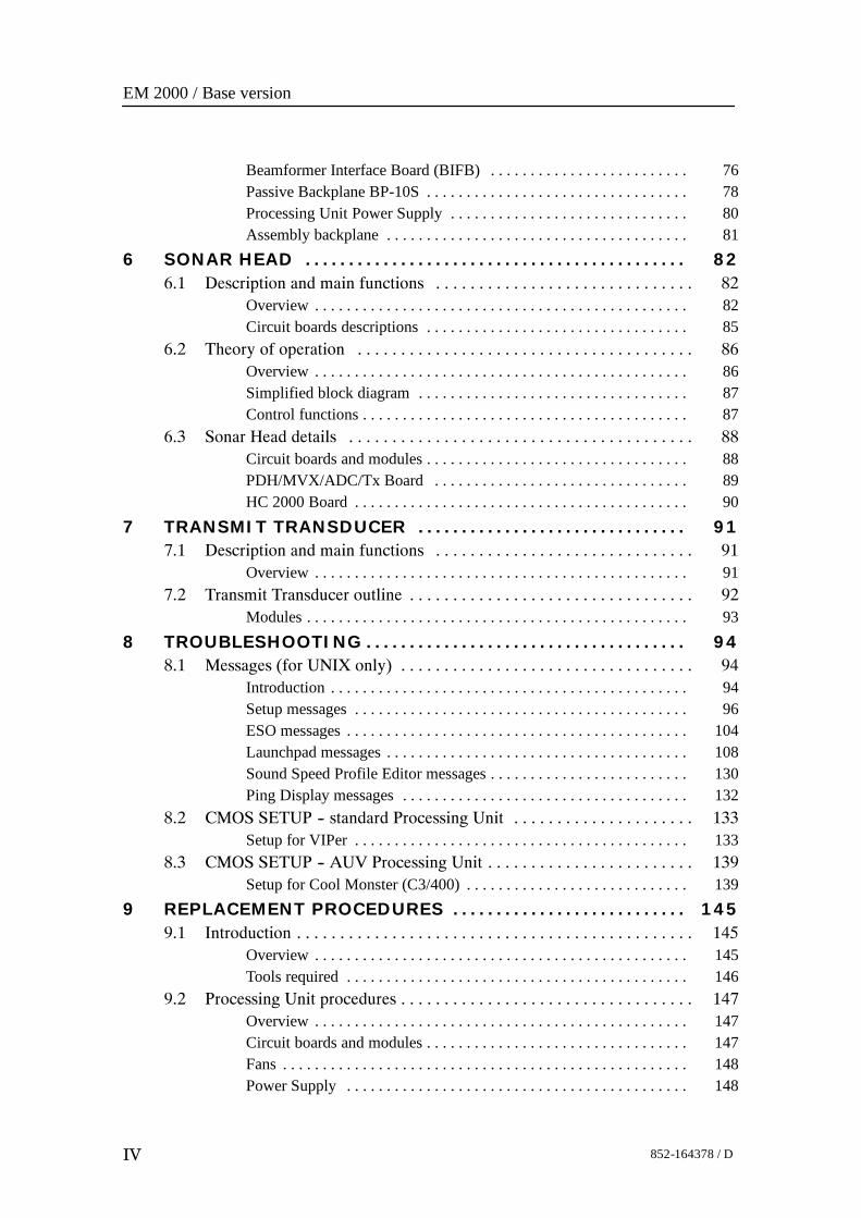
Beamformer Interface Board (BIFB) 76. . . . . . . . . . . . . . . . . . . . . . . . .Passive Backplane BP-10S 78. . . . . . . . . . . . . . . . . . . . . . . . . . . . . . . . .Processing Unit Power Supply 80. . . . . . . . . . . . . . . . . . . . . . . . . . . . . .Assembly backplane 81. . . . . . . . . . . . . . . . . . . . . . . . . . . . . . . . . . . . . .
6 SONAR HEAD 82. . . . . . . . . . . . . . . . . . . . . . . . . . . . . . . . . . . . . . . . . . . .6.1 Description and main functions 82. . . . . . . . . . . . . . . . . . . . . . . . . . . . . .
Overview 82. . . . . . . . . . . . . . . . . . . . . . . . . . . . . . . . . . . . . . . . . . . . . . .Circuit boards descriptions 85. . . . . . . . . . . . . . . . . . . . . . . . . . . . . . . . .
6.2 Theory of operation 86. . . . . . . . . . . . . . . . . . . . . . . . . . . . . . . . . . . . . . .Overview 86. . . . . . . . . . . . . . . . . . . . . . . . . . . . . . . . . . . . . . . . . . . . . . .Simplified block diagram 87. . . . . . . . . . . . . . . . . . . . . . . . . . . . . . . . . .Control functions 87. . . . . . . . . . . . . . . . . . . . . . . . . . . . . . . . . . . . . . . . .
6.3 Sonar Head details 88. . . . . . . . . . . . . . . . . . . . . . . . . . . . . . . . . . . . . . . .Circuit boards and modules 88. . . . . . . . . . . . . . . . . . . . . . . . . . . . . . . . .PDH/MVX/ADC/Tx Board 89. . . . . . . . . . . . . . . . . . . . . . . . . . . . . . . .HC 2000 Board 90. . . . . . . . . . . . . . . . . . . . . . . . . . . . . . . . . . . . . . . . . .
7 TRANSMIT TRANSDUCER 91. . . . . . . . . . . . . . . . . . . . . . . . . . . . . . .7.1 Description and main functions 91. . . . . . . . . . . . . . . . . . . . . . . . . . . . . .
Overview 91. . . . . . . . . . . . . . . . . . . . . . . . . . . . . . . . . . . . . . . . . . . . . . .7.2 Transmit Transducer outline 92. . . . . . . . . . . . . . . . . . . . . . . . . . . . . . . . .
Modules 93. . . . . . . . . . . . . . . . . . . . . . . . . . . . . . . . . . . . . . . . . . . . . . . .8 TROUBLESHOOTING 94. . . . . . . . . . . . . . . . . . . . . . . . . . . . . . . . . . . . .
8.1 Messages (for UNIX only) 94. . . . . . . . . . . . . . . . . . . . . . . . . . . . . . . . . .Introduction 94. . . . . . . . . . . . . . . . . . . . . . . . . . . . . . . . . . . . . . . . . . . . .Setup messages 96. . . . . . . . . . . . . . . . . . . . . . . . . . . . . . . . . . . . . . . . . .ESO messages 104. . . . . . . . . . . . . . . . . . . . . . . . . . . . . . . . . . . . . . . . . . .Launchpad messages 108. . . . . . . . . . . . . . . . . . . . . . . . . . . . . . . . . . . . . .Sound Speed Profile Editor messages 130. . . . . . . . . . . . . . . . . . . . . . . . .Ping Display messages 132. . . . . . . . . . . . . . . . . . . . . . . . . . . . . . . . . . . .
8.2 CMOS SETUP -- standard Processing Unit 133. . . . . . . . . . . . . . . . . . . . .Setup for VIPer 133. . . . . . . . . . . . . . . . . . . . . . . . . . . . . . . . . . . . . . . . . .
8.3 CMOS SETUP -- AUV Processing Unit 139. . . . . . . . . . . . . . . . . . . . . . . .Setup for Cool Monster (C3/400) 139. . . . . . . . . . . . . . . . . . . . . . . . . . . .
9 REPLACEMENT PROCEDURES 145. . . . . . . . . . . . . . . . . . . . . . . . . . .9.1 Introduction 145. . . . . . . . . . . . . . . . . . . . . . . . . . . . . . . . . . . . . . . . . . . . . .
Overview 145. . . . . . . . . . . . . . . . . . . . . . . . . . . . . . . . . . . . . . . . . . . . . . .Tools required 146. . . . . . . . . . . . . . . . . . . . . . . . . . . . . . . . . . . . . . . . . . .
9.2 Processing Unit procedures 147. . . . . . . . . . . . . . . . . . . . . . . . . . . . . . . . . .Overview 147. . . . . . . . . . . . . . . . . . . . . . . . . . . . . . . . . . . . . . . . . . . . . . .Circuit boards and modules 147. . . . . . . . . . . . . . . . . . . . . . . . . . . . . . . . .Fans 148. . . . . . . . . . . . . . . . . . . . . . . . . . . . . . . . . . . . . . . . . . . . . . . . . . .Power Supply 148. . . . . . . . . . . . . . . . . . . . . . . . . . . . . . . . . . . . . . . . . . .
Maintenance manual
V852-164378 / D
10 EM DATAGRAM FORMATS 149. . . . . . . . . . . . . . . . . . . . . . . . . . . . . . .
11 SYSTEM ADMINISTRATION (UNIX) 150. . . . . . . . . . . . . . . . . . . .11.1 Introduction 150. . . . . . . . . . . . . . . . . . . . . . . . . . . . . . . . . . . . . . . . . . . . . .
11.2 Passwords 151. . . . . . . . . . . . . . . . . . . . . . . . . . . . . . . . . . . . . . . . . . . . . . .
EM 2000 Installation setup 151. . . . . . . . . . . . . . . . . . . . . . . . . . . . . . . . .11.3 EM 2000 File system 152. . . . . . . . . . . . . . . . . . . . . . . . . . . . . . . . . . . . . .
Introduction 152. . . . . . . . . . . . . . . . . . . . . . . . . . . . . . . . . . . . . . . . . . . . .Survey files 152. . . . . . . . . . . . . . . . . . . . . . . . . . . . . . . . . . . . . . . . . . . . .Sound speed profiles 152. . . . . . . . . . . . . . . . . . . . . . . . . . . . . . . . . . . . . .Absorption coefficient file 153. . . . . . . . . . . . . . . . . . . . . . . . . . . . . . . . .Workstation I/O 153. . . . . . . . . . . . . . . . . . . . . . . . . . . . . . . . . . . . . . . . . .Echo sounder parameters 153. . . . . . . . . . . . . . . . . . . . . . . . . . . . . . . . . .BIST files 154. . . . . . . . . . . . . . . . . . . . . . . . . . . . . . . . . . . . . . . . . . . . . .Logfiles 155. . . . . . . . . . . . . . . . . . . . . . . . . . . . . . . . . . . . . . . . . . . . . . . .Operator configuration files 155. . . . . . . . . . . . . . . . . . . . . . . . . . . . . . . .Survey jobs 156. . . . . . . . . . . . . . . . . . . . . . . . . . . . . . . . . . . . . . . . . . . . .TOC files 156. . . . . . . . . . . . . . . . . . . . . . . . . . . . . . . . . . . . . . . . . . . . . . .
11.4 File formats 157. . . . . . . . . . . . . . . . . . . . . . . . . . . . . . . . . . . . . . . . . . . . . .
Introduction 157. . . . . . . . . . . . . . . . . . . . . . . . . . . . . . . . . . . . . . . . . . . . .Survey format and I/O library 157. . . . . . . . . . . . . . . . . . . . . . . . . . . . . . .The survey format 157. . . . . . . . . . . . . . . . . . . . . . . . . . . . . . . . . . . . . . . .
11.5 Survey Predefined Files 174. . . . . . . . . . . . . . . . . . . . . . . . . . . . . . . . . . . .
Introduction 174. . . . . . . . . . . . . . . . . . . . . . . . . . . . . . . . . . . . . . . . . . . . .File locations 174. . . . . . . . . . . . . . . . . . . . . . . . . . . . . . . . . . . . . . . . . . . .Using the Survey Predefined Files 174. . . . . . . . . . . . . . . . . . . . . . . . . . .Scope and purpose 175. . . . . . . . . . . . . . . . . . . . . . . . . . . . . . . . . . . . . . . .Projection overview 175. . . . . . . . . . . . . . . . . . . . . . . . . . . . . . . . . . . . . .Projection protocol 175. . . . . . . . . . . . . . . . . . . . . . . . . . . . . . . . . . . . . . .Notes 177. . . . . . . . . . . . . . . . . . . . . . . . . . . . . . . . . . . . . . . . . . . . . . . . . .
11.6 Dynamic Projection Library 178. . . . . . . . . . . . . . . . . . . . . . . . . . . . . . . . .
Introduction 178. . . . . . . . . . . . . . . . . . . . . . . . . . . . . . . . . . . . . . . . . . . . .Overview 178. . . . . . . . . . . . . . . . . . . . . . . . . . . . . . . . . . . . . . . . . . . . . . .Dynamic projection library definitions 178. . . . . . . . . . . . . . . . . . . . . . . .Dynamic projection library protocol 178. . . . . . . . . . . . . . . . . . . . . . . . . .Example 179. . . . . . . . . . . . . . . . . . . . . . . . . . . . . . . . . . . . . . . . . . . . . . . .Notes 184. . . . . . . . . . . . . . . . . . . . . . . . . . . . . . . . . . . . . . . . . . . . . . . . . .
EM 2000 / Base version
VI 852-164378 / D
12 SPARE PARTS 185. . . . . . . . . . . . . . . . . . . . . . . . . . . . . . . . . . . . . . . . . . . .12.1 Overview 185. . . . . . . . . . . . . . . . . . . . . . . . . . . . . . . . . . . . . . . . . . . . . . . .
12.2 Spares data presentation 185. . . . . . . . . . . . . . . . . . . . . . . . . . . . . . . . . . . .
Spares table 185. . . . . . . . . . . . . . . . . . . . . . . . . . . . . . . . . . . . . . . . . . . . .Parts list codes 186. . . . . . . . . . . . . . . . . . . . . . . . . . . . . . . . . . . . . . . . . . .
12.3 Operator Station (HWS 10) spare parts 187. . . . . . . . . . . . . . . . . . . . . . . .
12.4 Processing Unit spare parts 188. . . . . . . . . . . . . . . . . . . . . . . . . . . . . . . . . .
Standard Processing Unit spare parts 189. . . . . . . . . . . . . . . . . . . . . . . . .AUV Processing Unit spare parts 190. . . . . . . . . . . . . . . . . . . . . . . . . . . .
12.5 Sonar Head spare parts 192. . . . . . . . . . . . . . . . . . . . . . . . . . . . . . . . . . . . .

Maintenance manual
VII852-164378 / D
High voltage safety warning
Precautionary measuresThe voltages used to power this equipmentare potentially lethal. Even 110 volts can kill.Whenever possible, the followingprecautionary measures must be taken beforeany work is carried out inside the equipment:S Switch off all high-voltage power supplies.S Check the operation of any door interlocks
and any other safety devices.S Completely discharge all high-voltage
capacitors.It should be noted that interlocks and safetydevices are normally located only at regularaccess points, and high voltages may beexposed during dismantling.Never work alone on high-voltageequipment!
First aid in the event ofelectric shockNormally, even a high voltage electric shockwill not kill instantly. The victim can still berevived even when his breathing andheart-beat have ceased.Could YOU save someone’s life?In the event of electric shock, the correctactions, performed quickly may well save thevictim’s life. Make sure you know what todo!
Immediate action
While shouting for help, remove the source ofpower from the victim. Switch off the supplyif possible, or using a dry, non-conductivematerial (rubber gloves, broom handle etc.) toinsulate yourself, separate the victim from thesource. If the voltage exceeds 1000 volts,switch off the supply and be ready to catchthe victim. Take care- do not become a victimyourself.Commence first aid on the spot. Continue toshout for assistance till someone arrives.1 Lay the victim flat on his back and loosen
any tight clothing (collar, tie, belt etc.).
2 Open his mouth and check for and removeany false teeth, chewing gum etc.
3 Check if the victim is breathing. If not,check if his heart is beating. The pulse isnormally easily found in the main arteriesof the neck, either side of the throat, upunder the chin.
If his heart is beating but he is not breathing,commence artificial respiration. If thevictim’s heart is not beating, commenceexternal cardiac massage (ECM). Continue toshout for assistance till someone arrives.
External cardiac massage1 Kneel beside the victim. Place the heel of
one hand in the centre of his chest, at aposition half way between the notchbetween the collar-bones at the top of hischest, and the dip in the breast-bone at thebase of his rib cage. Place the other handon top of the first.
2 Keeping the arms straight and using yourentire weight, press down rapidly so thatthe breast bone is depressed four- five cm,then release the pressure. Repeatrhythmically at a rate of one cycle persecond. This will be hard work, but keepgoing. His life depends on YOU. Do notworry about breaking his ribs - these willheal if he survives.
EM 2000 / Base version
VIII 852-164378 / D
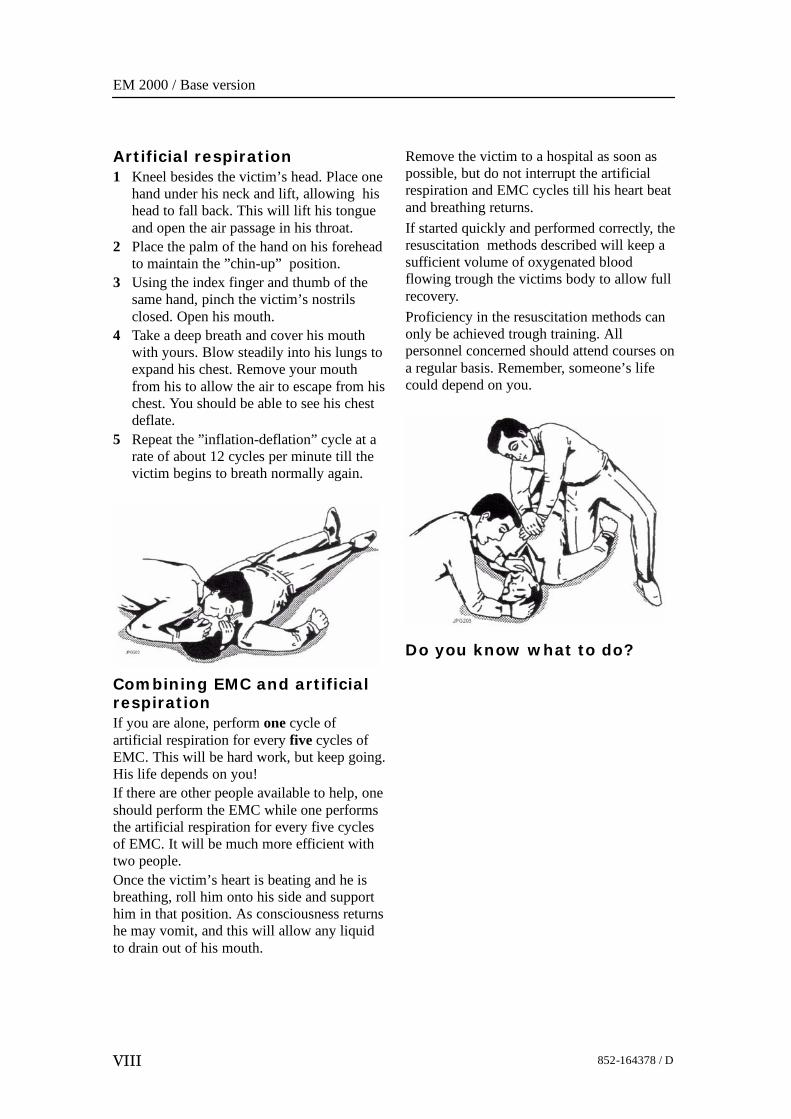
Artificial respiration1 Kneel besides the victim’s head. Place one
hand under his neck and lift, allowing hishead to fall back. This will lift his tongueand open the air passage in his throat.
2 Place the palm of the hand on his foreheadto maintain the ”chin-up” position.
3 Using the index finger and thumb of thesame hand, pinch the victim’s nostrilsclosed. Open his mouth.
4 Take a deep breath and cover his mouthwith yours. Blow steadily into his lungs toexpand his chest. Remove your mouthfrom his to allow the air to escape from hischest. You should be able to see his chestdeflate.
5 Repeat the ”inflation-deflation” cycle at arate of about 12 cycles per minute till thevictim begins to breath normally again.
Combining EMC and artificialrespirationIf you are alone, perform one cycle ofartificial respiration for every five cycles ofEMC. This will be hard work, but keep going.His life depends on you!If there are other people available to help, oneshould perform the EMC while one performsthe artificial respiration for every five cyclesof EMC. It will be much more efficient withtwo people.Once the victim’s heart is beating and he isbreathing, roll him onto his side and supporthim in that position. As consciousness returnshe may vomit, and this will allow any liquidto drain out of his mouth.
Remove the victim to a hospital as soon aspossible, but do not interrupt the artificialrespiration and EMC cycles till his heart beatand breathing returns.If started quickly and performed correctly, theresuscitation methods described will keep asufficient volume of oxygenated bloodflowing trough the victims body to allow fullrecovery.Proficiency in the resuscitation methods canonly be achieved trough training. Allpersonnel concerned should attend courses ona regular basis. Remember, someone’s lifecould depend on you.
Do you know what to do?
Introduction
1852-164378 / D
1 INTRODUCTION
1.1 GeneralThis is the maintenance manual for the EM 2000 multibeamecho sounder system.
Note This manual is common for the AUV Processing Unit and theStandard Processing Unit.
The manual contains detailed descriptions of each of the units inthe system. Each circuit board and mechanical assembly isdescribed. The manual also describes the troubleshootingprocess based on the Built-In Self test (BIST) software, and itincludes procedures for disassembly and reassembly of thereplaceable items.This manual does not describe the maintenance of the OperatorStation and the peripheral devices (printers, plotters andsensors). For information about these items, refer to theapplicable manufacturer’s documentation.
Topics
→ Maintenance philosophy, page 2→ System overview, page 3→ System drawing, page 4 and 5→ General sefety rules, page 6
EM 2000 / Base version
2 852-164378 / D
1.2 Maintenance philosophyKongsberg Maritime AS defines three levels for maintenancemanuals:Organizational - You will only perform limited preventive andcorrective maintenance on the system. There is no need fortechnical education or training, and no need for any instruments.Typical tasks are exterior cleaning, or changing fuses.Intermediate - You will perform overall preventive andcorrective maintenance on the system. It is recommended thatyou are an educated engineer with experience fromcomputerized design and mechanical systems. It is furtherexpected that you can use standard electronic instruments, suchas an oscilloscope. You should be trained by KongsbergMaritime to perform maintenance on the system. Typical tasksmay include troubleshooting, testing and circuit boardreplacement.Depot - You will perform detailed maintenance on the systemand on the circuit boards and modules. You must be an educatedengineer with experience of computerized design andmechanical systems. It is further expected that you can usestandard electronic instruments, such as an oscilloscope. Youshould be trained by Kongsberg Maritime to performmaintenance on the system. Typical tasks are circuit boardrepair.
Note This maintenance manual is prepared for the intermediate level.
Introduction
3852-164378 / D
1.3 System overviewThe EM 2000 multibeam echo sounder is a shallow watermapping and inspection system with very high accuracy andresolution.The minimum operating depth is from less than 2.5 m below itstransducers, and in typical sea water conditions the systemoperates to 350 to 400 m depth (less in warm water and more infresh water). Small dimensions and low weight makes thesystem portable and easy to install allowing use both on surveylaunches and subsea vehicles to 6000 m water depth.The EM 2000 system has a high ping rate of up to 10 Hz. Itoperates with 111 roll stabilised beams per ping with 1.5°beamwidth along and 1.5° acrosstrack dependent upon sonarhead model. With the narrowest acrosstrack beamwidth thesystem has an angular coverage of more than 120 degrees, andwith the widest the angular coverage is more than 150 degrees.The achievable coverage may be more than to 300 m. The beamspacing is operator adjustable to be either equiangle, equidistantor in-between. Angular coverage is also operator adjustable,always retaining the full number of beams within the definedcoverage sector.The system sonar frequency is 200 kHz, allowing smalldimensions, good range capability and high tolerance to turbidwaters.Integrated seabed acoustical imaging capability (sidescan) isincluded as standard. A combination of phase and amplitudedetection is used, resulting in a measurement accuracy of 8 cmRMS being achievable practically independent of beam pointingangle.The EM 2000 is a complete system with all necessary sensorinterfaces, real-time compensation for vessel motion andray-bending, data displays for quality control including sensorcalibration, and data logging included as standard.
Postprocessing software for the EM 2000 is available from bothKongsberg Maritime and third-party suppliers. A world-widemarketing and service organization having many years ofmultibeam experience is available for supporting the EM 2000.
EM 2000 / Base version
4 852-164378 / D
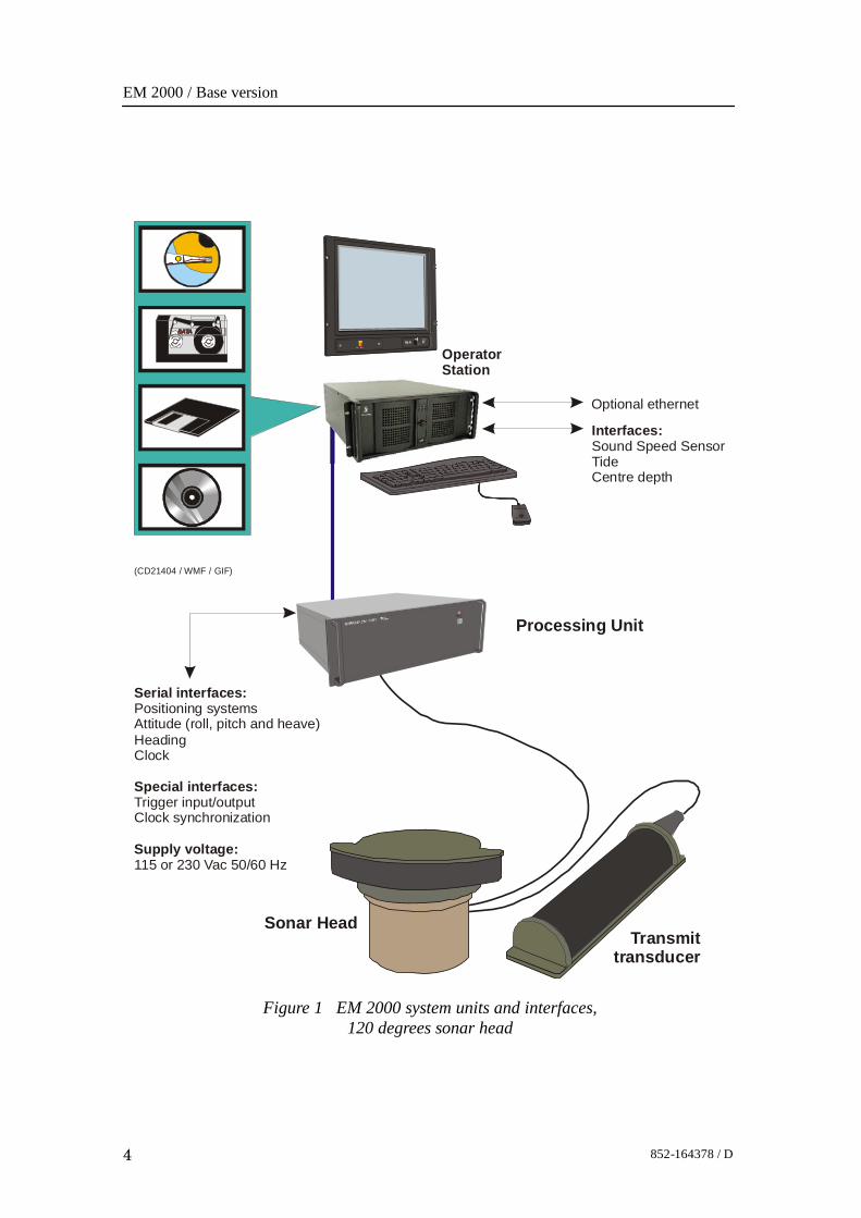
Figure 1 EM 2000 system units and interfaces,120 degrees sonar head
(CD21404 / WMF / GIF)
Processing Unit
Sonar HeadTransmit
transducer
Serial interfaces:
Special interfaces:
Supply voltage:
Positioning systemsAttitude (roll, pitch and heave)HeadingClock
Trigger input/outputClock synchronization
115 or 230 Vac 50/60 Hz
Interfaces:Sound Speed SensorTideCentre depth
Optional ethernet
OperatorStation
Introduction
5852-164378 / D
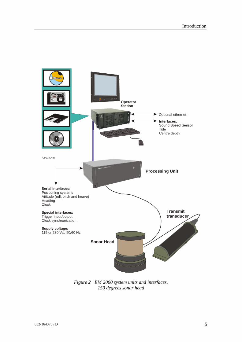
Figure 2 EM 2000 system units and interfaces,150 degrees sonar head
(CD21404B)
Processing Unit
Sonar Head
Transmittransducer
Interfaces:Sound Speed SensorTideCentre depth
Optional ethernet
Serial interfaces:
Special interfaces:
Supply voltage:
Positioning systemsAttitude (roll, pitch and heave)HeadingClock
Trigger input/outputClock synchronization
115 or 230 Vac 50/60 Hz
OperatorStation
EM 2000 / Base version
6 852-164378 / D
1.4 General safety rulesThe system operates on 115 and/or 230 Vac, 50/60 Hz withoutany need for wiring changes.
Warning This voltage can be lethal.
The following safety precautions must be followed at all timesduring installation and maintenance work:• Always switch off all power before installation or
maintenance. Use the main circuit breaker, and label thebreaker with a warning sign that informs others thatmaintenance or installation work is being carried out on thesystem.
• For safety reasons during troubleshooting on the equipmentwith power ON, two persons should always be present.
• Whenever maintenance is carried out, it is essential that afirst aid kit is available, and that the maintenance personnelare familiar with the first aid instructions for electrical shock.
• The various parts of the system are heavy. Make sure that theappropriate tools and certified lifting equipment areavailable, and that the personnel are trained in installationand maintenance work.
Technical specification
7852-164378 / D
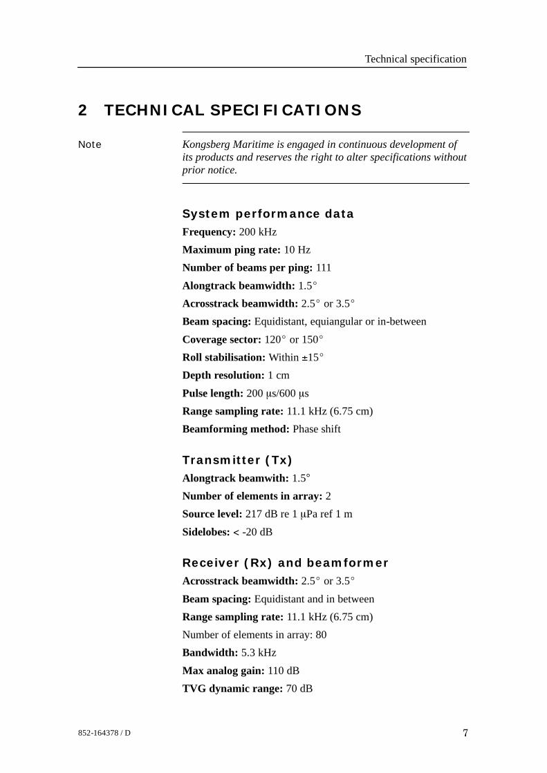
2 TECHNICAL SPECIFICATIONS
Note Kongsberg Maritime is engaged in continuous development ofits products and reserves the right to alter specifications withoutprior notice.
System performance dataFrequency: 200 kHzMaximum ping rate: 10 HzNumber of beams per ping: 111Alongtrack beamwidth: 1.5_Acrosstrack beamwidth: 2.5_ or 3.5_Beam spacing: Equidistant, equiangular or in-betweenCoverage sector: 120_ or 150_Roll stabilisation: Within ±15_Depth resolution: 1 cmPulse length: 200 ms/600 msRange sampling rate: 11.1 kHz (6.75 cm)Beamforming method: Phase shift
Transmitter (Tx)Alongtrack beamwith: 1.5°Number of elements in array: 2Source level: 217 dB re 1 mPa ref 1 mSidelobes: < -20 dB
Receiver (Rx) and beamformerAcrosstrack beamwidth: 2.5_ or 3.5_Beam spacing: Equidistant and in betweenRange sampling rate: 11.1 kHz (6.75 cm)Number of elements in array: 80Bandwidth: 5.3 kHzMax analog gain: 110 dBTVG dynamic range: 70 dB
EM 2000 / Base version
8 852-164378 / D
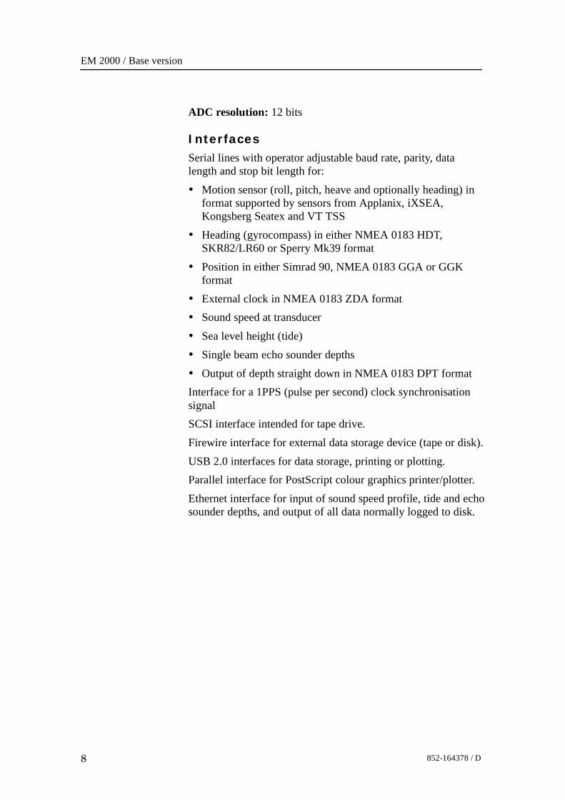
ADC resolution: 12 bits
InterfacesSerial lines with operator adjustable baud rate, parity, datalength and stop bit length for:• Motion sensor (roll, pitch, heave and optionally heading) in
format supported by sensors from Applanix, iXSEA,Kongsberg Seatex and VT TSS
• Heading (gyrocompass) in either NMEA 0183 HDT,SKR82/LR60 or Sperry Mk39 format
• Position in either Simrad 90, NMEA 0183 GGA or GGKformat
• External clock in NMEA 0183 ZDA format• Sound speed at transducer• Sea level height (tide)• Single beam echo sounder depths• Output of depth straight down in NMEA 0183 DPT formatInterface for a 1PPS (pulse per second) clock synchronisationsignalSCSI interface intended for tape drive.Firewire interface for external data storage device (tape or disk).USB 2.0 interfaces for data storage, printing or plotting.Parallel interface for PostScript colour graphics printer/plotter.
Ethernet interface for input of sound speed profile, tide and echosounder depths, and output of all data normally logged to disk.
Technical specification
9852-164378 / D
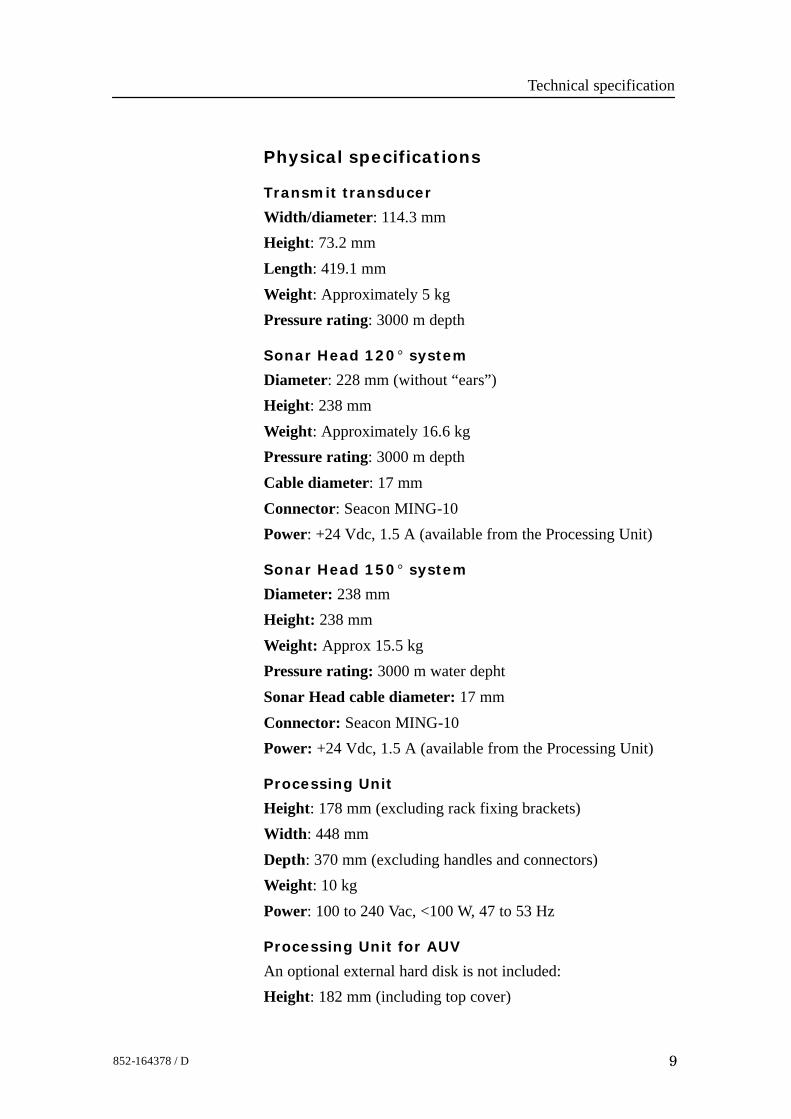
Physical specifications
Transmit transducer
Width/diameter: 114.3 mmHeight: 73.2 mmLength: 419.1 mmWeight: Approximately 5 kgPressure rating: 3000 m depth
Sonar Head 120_ system
Diameter: 228 mm (without “ears”)Height: 238 mmWeight: Approximately 16.6 kgPressure rating: 3000 m depthCable diameter: 17 mmConnector: Seacon MING-10Power: +24 Vdc, 1.5 A (available from the Processing Unit)
Sonar Head 150_ system
Diameter: 238 mmHeight: 238 mmWeight: Approx 15.5 kgPressure rating: 3000 m water dephtSonar Head cable diameter: 17 mmConnector: Seacon MING-10Power: +24 Vdc, 1.5 A (available from the Processing Unit)
Processing Unit
Height: 178 mm (excluding rack fixing brackets)Width: 448 mmDepth: 370 mm (excluding handles and connectors)Weight: 10 kgPower: 100 to 240 Vac, <100 W, 47 to 53 Hz
Processing Unit for AUV
An optional external hard disk is not included:Height: 182 mm (including top cover)
EM 2000 / Base version
10 852-164378 / D
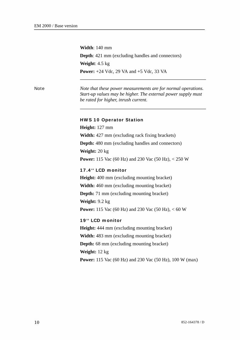
Width: 140 mmDepth: 421 mm (excluding handles and connectors)Weight: 4.5 kgPower: +24 Vdc, 29 VA and +5 Vdc, 33 VA
Note Note that these power measurements are for normal operations.Start-up values may be higher. The external power supply mustbe rated for higher, inrush current.
HWS 10 Operator Station
Height: 127 mmWidth: 427 mm (excluding rack fixing brackets)Depth: 480 mm (excluding handles and connectors)Weight: 20 kgPower: 115 Vac (60 Hz) and 230 Vac (50 Hz), < 250 W
17.4‘‘ LCD monitor
Height: 400 mm (excluding mounting bracket)Width: 460 mm (excluding mounting bracket)Depth: 71 mm (excluding mounting bracket)Weight: 9.2 kgPower: 115 Vac (60 Hz) and 230 Vac (50 Hz), < 60 W
19‘‘ LCD monitor
Height: 444 mm (excluding mounting bracket)Width: 483 mm (excluding mounting bracket)Depth: 68 mm (excluding mounting bracket)Weight: 12 kgPower: 115 Vac (60 Hz) and 230 Vac (50 Hz), 100 W (max)
Technical specification
11852-164378 / D
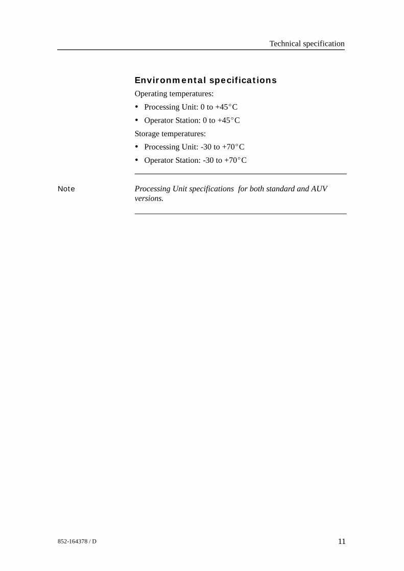
Environmental specificationsOperating temperatures:• Processing Unit: 0 to +45_C• Operator Station: 0 to +45_CStorage temperatures:• Processing Unit: -30 to +70_C• Operator Station: -30 to +70_C
Note Processing Unit specifications for both standard and AUVversions.

EM 2000 / Base version
12 852-164378 / D
3 CABLE LAYOUT
3.1 IntroductionThis chapter describes the standard cables used between the EM2000 system units and between the units and their externaldevices.
Note All electronic installations and corresponding wiring must be inaccordance with the vessel’s national registry andcorresponding maritime authority end/or classification society.
If no such guidelines exist, Kongsberg Maritime ASrecommends that Det norske Veritas (DNV) Report No. 80-P008«Guidelines for Installation and Proposal for Test ofEquipment» be used as a guide.Contact information:DNVCorporate HeadquartersVeritasveien 11322 HøvikNorwayhttp://www.dnv.com
Topics
→ System cabling, page13→ Cable plan - Operator Station, page14→ Cable plan -Processing Unit, page 15→ Cable plan - AUV Processing Unit, page 16→ EM 2000 AUV Processing Unit cabling details, page 17→ Cable specifications, page 18→ Sonar Head Connections, page 45→ Cable drawing list, page 23→ Cable drawings, page 24→ Basic cabling requirements, page 46
Cable layout and interconnections
13852-164378 / D
3.2 System cabling
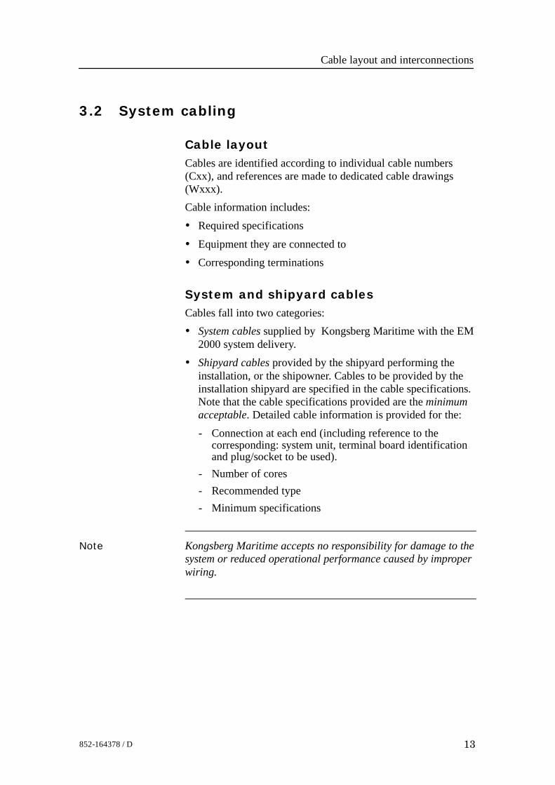
Cable layoutCables are identified according to individual cable numbers(Cxx), and references are made to dedicated cable drawings(Wxxx).Cable information includes:• Required specifications
• Equipment they are connected to• Corresponding terminations
System and shipyard cablesCables fall into two categories:• System cables supplied by Kongsberg Maritime with the EM
2000 system delivery.• Shipyard cables provided by the shipyard performing the
installation, or the shipowner. Cables to be provided by theinstallation shipyard are specified in the cable specifications.Note that the cable specifications provided are the minimumacceptable. Detailed cable information is provided for the:- Connection at each end (including reference to the
corresponding: system unit, terminal board identificationand plug/socket to be used).
- Number of cores- Recommended type- Minimum specifications
Note Kongsberg Maritime accepts no responsibility for damage to thesystem or reduced operational performance caused by improperwiring.
EM 2000 / Base version
14 852-164378 / D
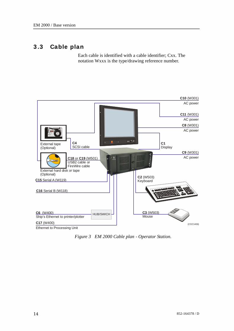
3.3 Cable planEach cable is identified with a cable identifier; Cxx. Thenotation Wxxx is the type/drawing reference number.
Figure 3 EM 2000 Cable plan - Operator Station.
External tape(Optional)
(CD21406)
C4SCSI cable
C3Mouse
(W503)
C1Display
C2 5 3Keyboard
(W 0 )
C8 (W301)AC power
C10 (W301)AC power
C9 AC power
(W301)
C11 AC power
(W301)
C17 (W400)Ethernet to Processing Unit
C6 400Ship’s Ethernet to printer/plotter
(W )
C16 Serial B (W118)
C15 Serial A (W119)
External hard disk or tape(Optional)
C18 C19 or (W501)USB2 cable or FireWire cable
HUB/SWICH
Cable layout and interconnections
15852-164378 / D
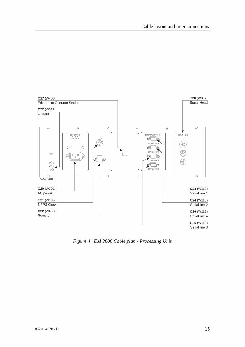
Figure 4 EM 2000 Cable plan - Processing Unit
SERIAL PORT 1
SERIAL PORT 2
SERIAL PORT 3
SERIAL PORT 4
1 PPS
Remote
(CD21405B)
C23 (W118)Serial line 1
C28 (W807)Sonar Head
C24 (W118)Serial line 2
C25 (W118)Serial line 3
C26 (W118)Serial line 4
C20 (W301)AC power
C21 (W105)1 PPS Clock
C27 (W311)Ground
C17 (W400)Ethernet to Operator Station
EXTERNAL SENSORS SONAR HEAD100 - 240 VAC50 - 60 HzMax 6 Amp
C22 (W600)Remote
EM 2000 / Base version
16 852-164378 / D
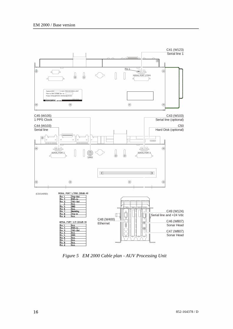
Figure 5 EM 2000 Cable plan - AUV Processing Unit
SERIAL PORT 1/TRIG
Pin 1
System:EM / AUV PROCESSING UNIT
Part no 299-215988 Ser. no Power:33Vac@5VDC 29VA22@24VDC
M a de in Nor way
C41Serial line 1
(W123)
C49 (W124)Serial line and +24 Vdc
C44 (W103)Serial line
C47Sonar Head
(W807)
(CD21405D)
C43 (W103)Serial line (optional)
C46 (W807)Sonar Head
C45 (W105)1 PPS Clock
C50Hard Disk (optional)
C48 (W400)Ethernet
1PPS
SERIAL PORT 2 SERIAL PORT 3
Cable layout and interconnections
17852-164378 / D
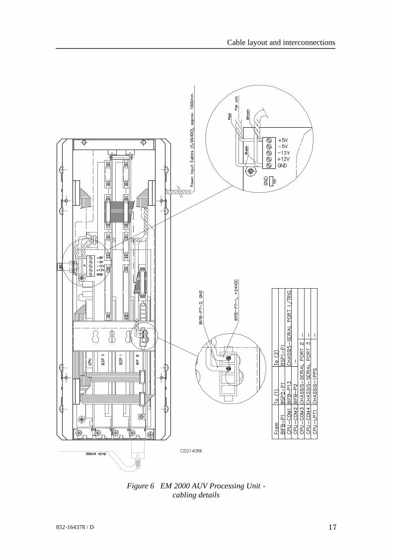
Figure 6 EM 2000 AUV Processing Unit -cabling details
CD21408B
EM 2000 / Base version
18 852-164378 / D
3.4 Cable specificationsEach cable is identified with a cable identifier; Cxx.The termination of all the cables into plugs or terminal blocksare shown on the referenced pages.
Operator Station cables
C1 Display monitor (video signal)
This is a standard display cable provided with the display Thephysical properties of the cable is not specified in thisdocumentation.→ Cable details on page 39
C2 Keyboard
This is a standard keyboard cable provided with the keyboard.The physical properties of the cable is not specified in thisdocumentation.→ Cable details on page 36
C3 Mouse
This is a standard mouse cable provided with the mouse. Thephysical properties of the cable is not specified in thisdocumentation.→ Cable details on page 37
C4 SCSI external harddisk storage (optional)
This is a standard SCSI cable that can be provided with theOperator Station. The physical properties of the cable is notspecified in this documentation.
C6 Printer/Plotter (optional)
This is a standard CAT-5 ethernet cable, and must be providedby the installation shipyard.→ Cable details on page 33
C8 AC power display
This is a standard AC power cable. The physical properties ofthe cable is not specified in this documentation.→ Cable details on page 31
Cable layout and interconnections
19852-164378 / D
C9 AC power operator station
This is a standard AC power cable. The physical properties ofthe cable is not specified in this documentation.→ Cable details on page 31
C10 AC power external tape storage
This is a standard AC power cable. The physical properties ofthe cable is not specified in this documentation.→ Cable details on page 31
C11 power external harddisk storage
This is a standard AC power cable. The physical properties ofthe cable is not specified in this documentation.→ Cable details on page 31
C15 Sound speed sensor
Sound speed probe interface→ Cable details on page 27
C16 Depth/tide
Generic RS-232 Serial line.→ Cable details on page 26
C17 Ethernet to Processing Unit
This is a standard CAT-5 ethernet cable, and must be providedby the installation shipyard.→ Cable details on page 33
C5, 7, 12,13,14,18 and 19 not in use.
Note These are standard computer cables provided with the OperatorStation. The physical properties of these cables are not specifiedin this documentation.
Note W400 is a fixed length ethernet cable supplied with the system.If required, the cable can be extended.
Note A synchronization system may be used when more than one echosounder or sonar system are used simultaneously.
EM 2000 / Base version
20 852-164378 / D
Processing Unit cables
C17 Ethernet to Operator Station
This is a standard CAT-5 ethernet cable, and must be providedby the installation shipyard.→ Cable details on page 33
C20 AC power
This is a standard AC power cable. The physical properties ofthe cable is not specified in this dokumentation.→ Cable details on page 31
C21 1 PPS Clock
Generic coax cable.→ Cable details on page 25
C22 Remote
Remote synchronization.40→ Cable details on page 40
C23 Serial line 1
Generic RS-232 with CTS and RTS→ Cable details on page 26
C24 Serial line 2
Generic RS-232 with CTS and RTS→ Cable details on page 26
C25 Serial line 3
Generic RS-232 with CTS and RTS→ Cable details on page 26
C26 Serial line 4
Generic RS-232 with CTS and RTS→ Cable details on page 26
C27 Ground
The physical properites of the cable is not specified in thisdokumentation.→ Cable details on page 32
C28 Sonar Head→ Cable details on page 41
C29 ... C40 not in use.
Cable layout and interconnections
21852-164378 / D
AUV Unit Cables
C41 / C43 / C44 - Serial lines
The AUV Processing Unit is equipped with three RS-232 seriallines. All connectors are 9-pin male D-connectors.
Cable C41 is a serial line with trigger input.
→ Cable details (C41) on page 28.
→ Cable details (C43, C44) on page 24.
Some sensors may require RTS and CTS.
→ Refer to the cable description on page 26.
The cables must be provided by the installation shipyard.
C45 - 1PPS
This is a timing signal terminated in a coax connector.
→ Cable details on page 25.
The cable must be provided by the installation shipyard.
C46 / C47 - Transducer cable to Sonar Head
The standard Sonar Head cable delivered by KongsbergMaritime has three plugs for connection to the standardProcessing Unit. These plugs must be substituted by oneunderwater plug with minimum 10 pins.
A 4 meter cable without connectors in the “Processing Unitend” is available from Kongsberg Maritime.
This can be ordered on registration number:
• 380 - 212985.
Internal wiring inside the bottle
Cabling from the underwater plug to the AUV Processing UnitBIFB board:
• Two mini coax cables must be used for the TAXI high speedup-link.
• A multi wire cable must be used to connect 24 V, RS-485serial line.
Plug and cable specifications (not supplied by KongsbergMaritime):
• 2 mini coax connectors to plug into the BIFB board.
EM 2000 / Base version
22 852-164378 / D
• 2 mini coax cable for the TAXI link.→ Cable details on page 30.
C48 - AUV Processing Unit RJ-45 interface
Refer to the Operator Station cabling.
C49 - Serial line and power
The AUV Processing Unit is equipped with one RS-485 serialline with +24 Vdc power input. The connector is a 9-pin maleD-connector.:• Plug for power and serial link for connection to the BIFB
board: standard 9 pins delta plug.- Minimums cable dimensions: 0.5 mm2.
→ Cable details on page 29.
C50 - Hard disk (optional)
This is a standard hard disk cable. The physical properties ofthese cables are not specified in this documentation.
Power cables
The AUV Processing Unit uses +5 Vdc and +24 Vdc for theSonar Head. These cables are delivered without connectors.100 cm cables are supplied by Kongsberg Maritime. Theyshould be shortened as much as possible to minimize voltagedrop.
The power cables are brown for +5 V and red for +24 V. Bothuse black as ground.The 5 V ground and the 24 V ground must be connectedtogether externally.Power requirements: 24 Vdc, 29 VA and 5Vdc, 33 VA.
Note The 5 V power measured at the motherboard terminals shouldbe minimum 5.0 Vdc. The 5 V power should be rated forminimum 12 A and 24 V power should be rated for minimum1.5 A.
Cable layout and interconnections
23852-164378 / D
3.5 Cable drawing list→ W103 - Generic RS-232 Serial line, page 24→ W105 - Generic coax cable, page 25→ W118 - Generic RS-232 with CTS and RTS, page 26→ W119 - Sound speed probe interface, page 27→ W123 - RS-232 Serial line with Trigger signals, page 28→ W124 - RS-485 Serial line and power, page 29→ W125 - Mini Coax, page 30→ W301 - Standard AC power cable, page 31→ W311 - EMC ground, page 32→ W400 - Ethernet with RJ45 plugs (screened), page 33→ W404- Ethernet with IEEE 802.3, page 34→ W501 - Standard USB cable, page 35→ W503 - Keyboard cable, page 36→ W504 - Mouse or pointing device cable, page 37→ W505 - Printer cable, page 38→ W508 - Digital Video Interface (DVI) display cable, page 39→ W600 - Remote synchronization, page 40→ W807 - Sonar Head cable, page 41→ Sonar Head cable drawings, page 42
EM 2000 / Base version
24 852-164378 / D
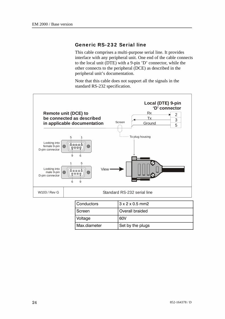
Generic RS-232 Serial lineThis cable comprises a multi-purpose serial line. It providesinterface with any peripheral unit. One end of the cable connectsto the local unit (DTE) with a 9-pin ’D’ connector, while theother connects to the peripheral (DCE) as described in theperipheral unit’s documentation.Note that this cable does not support all the signals in thestandard RS-232 specification.
W103 / Rev G Standard RS-232 serial line
235
RxTx
Ground
View
Local (DTE) 9-pin‘D’ connector
Remote unit (DCE) tobe connected as describedin applicable documentation
Looking intofemale 9-pin
D-pin connector
5 1
69
Looking intomale 9-pin
D-pin connector
1 5
96
Screen
To plug housing
Conductors 3 x 2 x 0.5 mm2
Screen Overall braided
Voltage 60V
Max.diameter Set by the plugs
Cable layout and interconnections
25852-164378 / D
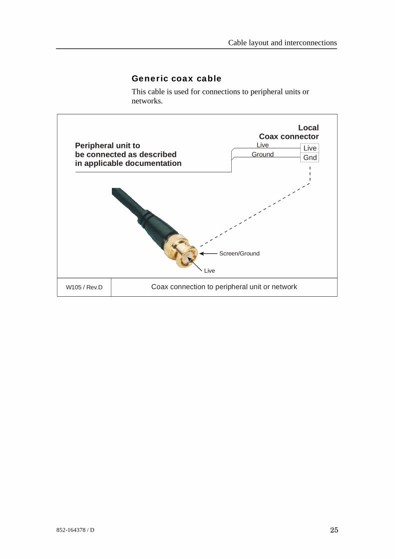
Generic coax cableThis cable is used for connections to peripheral units ornetworks.
W105 / Rev.D Coax connection to peripheral unit or network
LiveGnd
LiveGround
LocalCoax connector
Peripheral unit tobe connected as describedin applicable documentation
Live
Screen/Ground
EM 2000 / Base version
26 852-164378 / D
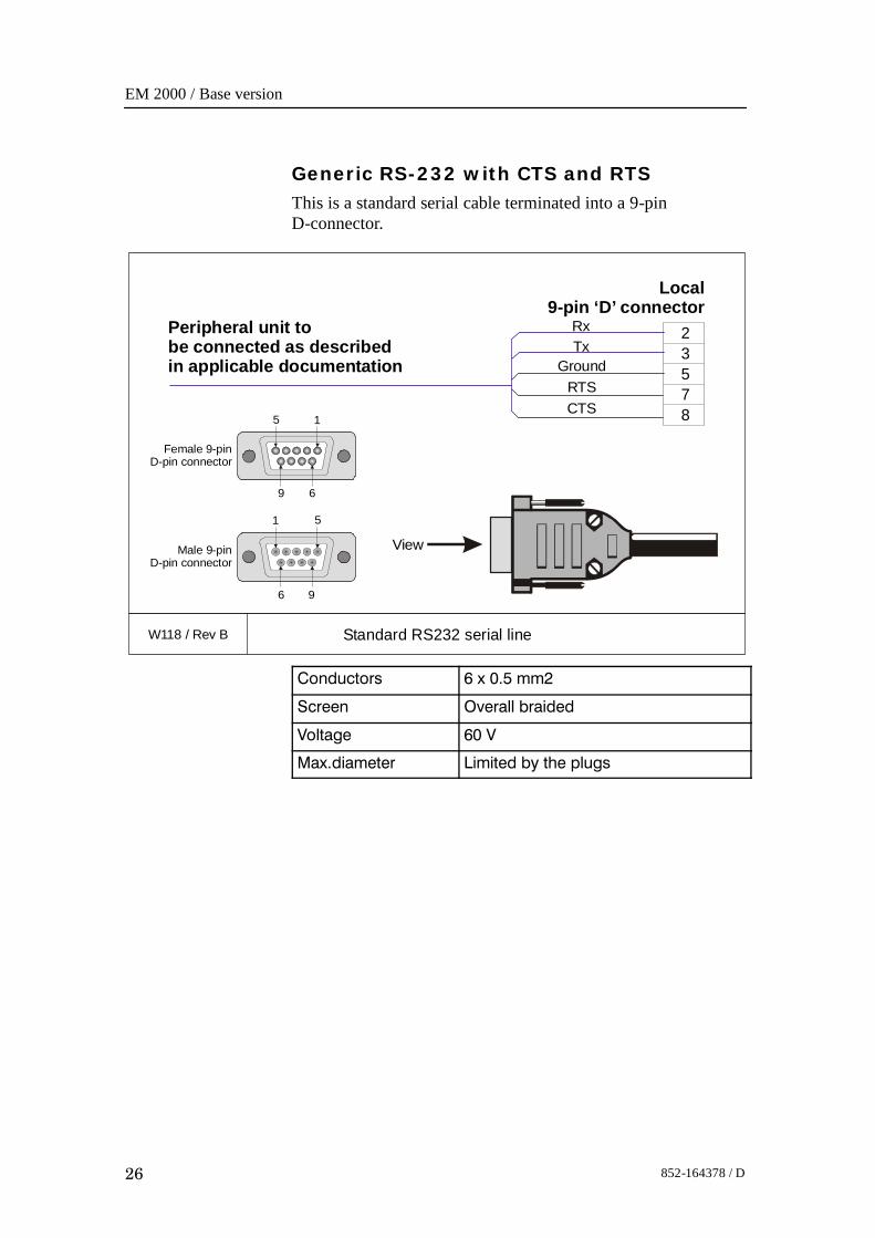
Generic RS-232 with CTS and RTSThis is a standard serial cable terminated into a 9-pinD-connector.
W118 / Rev B Standard RS232 serial line
2
7
3
8
5
RxTx
GroundRTSCTS
View
Local9-pin ‘D’ connector
Peripheral unit tobe connected as describedin applicable documentation
9 6
Female 9-pinD-pin connector
15
Male 9-pinD-pin connector
51
6 9
Conductors 6 x 0.5 mm2
Screen Overall braided
Voltage 60 V
Max.diameter Limited by the plugs
Cable layout and interconnections
27852-164378 / D
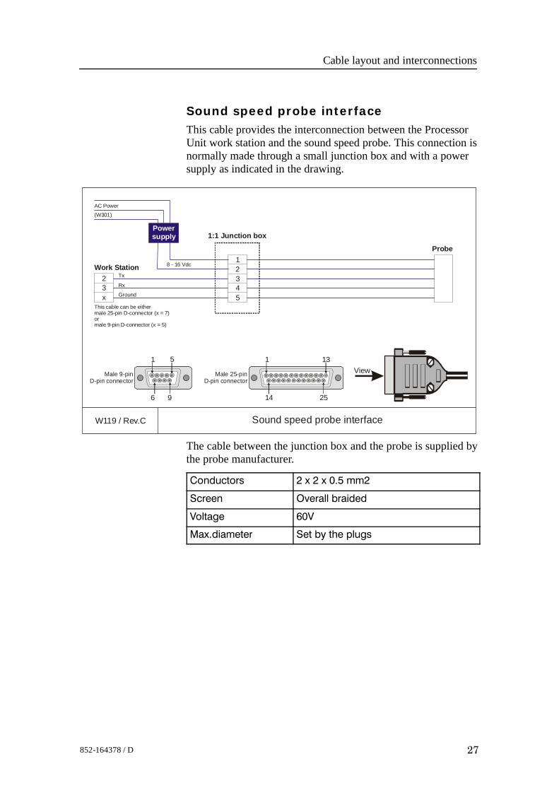
Sound speed probe interfaceThis cable provides the interconnection between the ProcessorUnit work station and the sound speed probe. This connection isnormally made through a small junction box and with a powersupply as indicated in the drawing.
W119 / Rev.C Sound speed probe interface
This cable can be either male 25-pin D-connector (x = 7) ormale 9-pin D-connector (x = 5)
8 - 16 Vdc
AC Power
(W301)
Tx
Rx
Ground
2
1
5432
3x
Male 25-pinD-pin connector
14 25
131
1:1 Junction box
Probe
Work Station
Powersupply
ViewMale 9-pinD-pin connector
6 9
51
The cable between the junction box and the probe is supplied bythe probe manufacturer.
Conductors 2 x 2 x 0.5 mm2
Screen Overall braided
Voltage 60V
Max.diameter Set by the plugs
EM 2000 / Base version
28 852-164378 / D
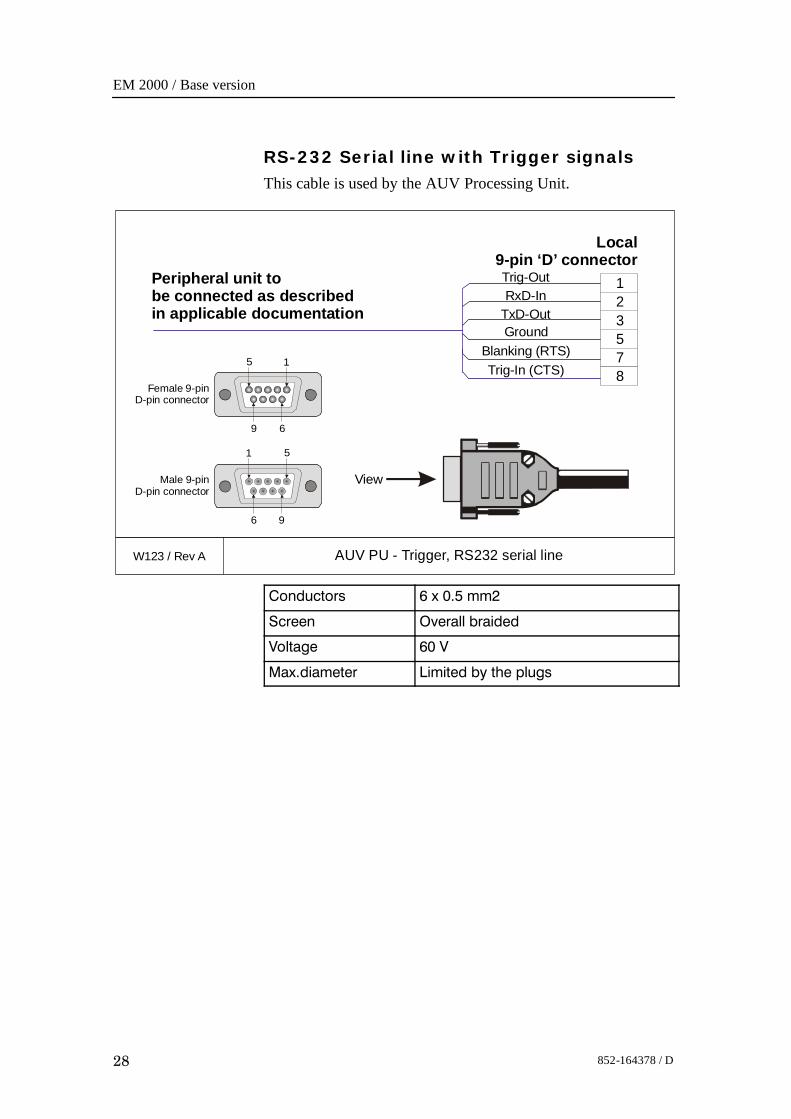
RS-232 Serial line with Trigger signalsThis cable is used by the AUV Processing Unit.
W123 / Rev A AUV PU - Trigger, RS232 serial line
2
7
3
8
5
RxD-InTxD-OutGround
Blanking (RTS)Trig-In (CTS)
View
Local9-pin ‘D’ connector
Peripheral unit tobe connected as describedin applicable documentation
9 6
Female 9-pinD-pin connector
15
Male 9-pinD-pin connector
51
6 9
1Trig-Out
Conductors 6 x 0.5 mm2
Screen Overall braided
Voltage 60 V
Max.diameter Limited by the plugs
Cable layout and interconnections
29852-164378 / D
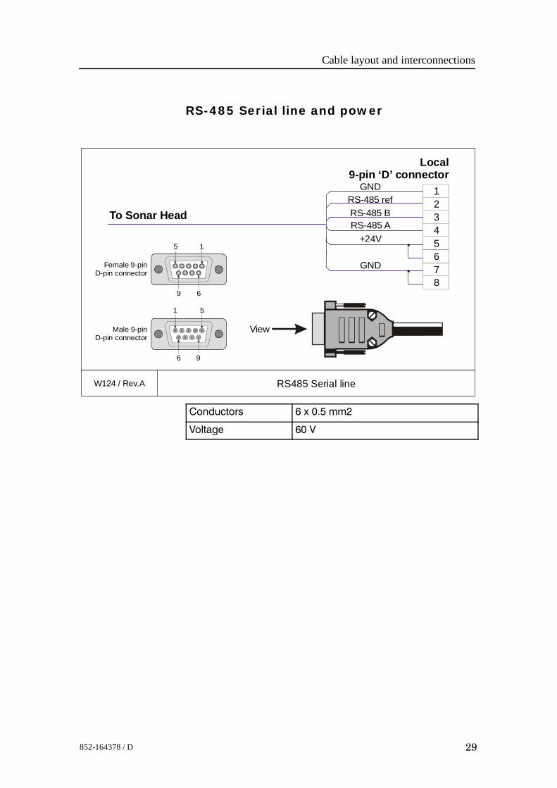
RS-485 Serial line and power
W124 / Rev.A RS485 Serial line
2
7
3
8
4
RS-485 refRS-485 BRS-485 A
+24V
GND
View
Local9-pin ‘D’ connector
To Sonar Head
9 6
Female 9-pinD-pin connector
15
Male 9-pinD-pin connector
51
6 9
1GND
56
Conductors 6 x 0.5 mm2
Voltage 60 V
EM 2000 / Base version
30 852-164378 / D
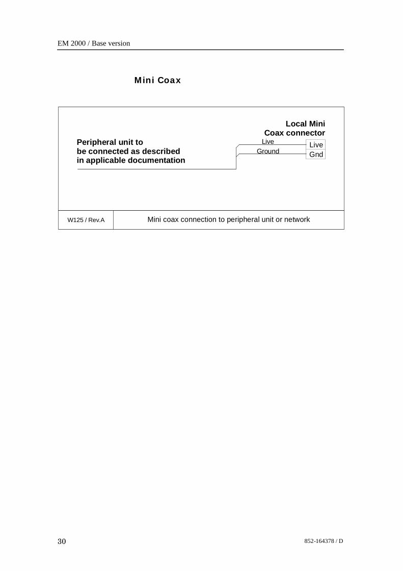
Mini Coax
W125 / Rev.A Mini coax connection to peripheral unit or network
LiveGnd
LiveGround
Local MiniCoax connector
Peripheral unit tobe connected as describedin applicable documentation
Cable layout and interconnections
31852-164378 / D
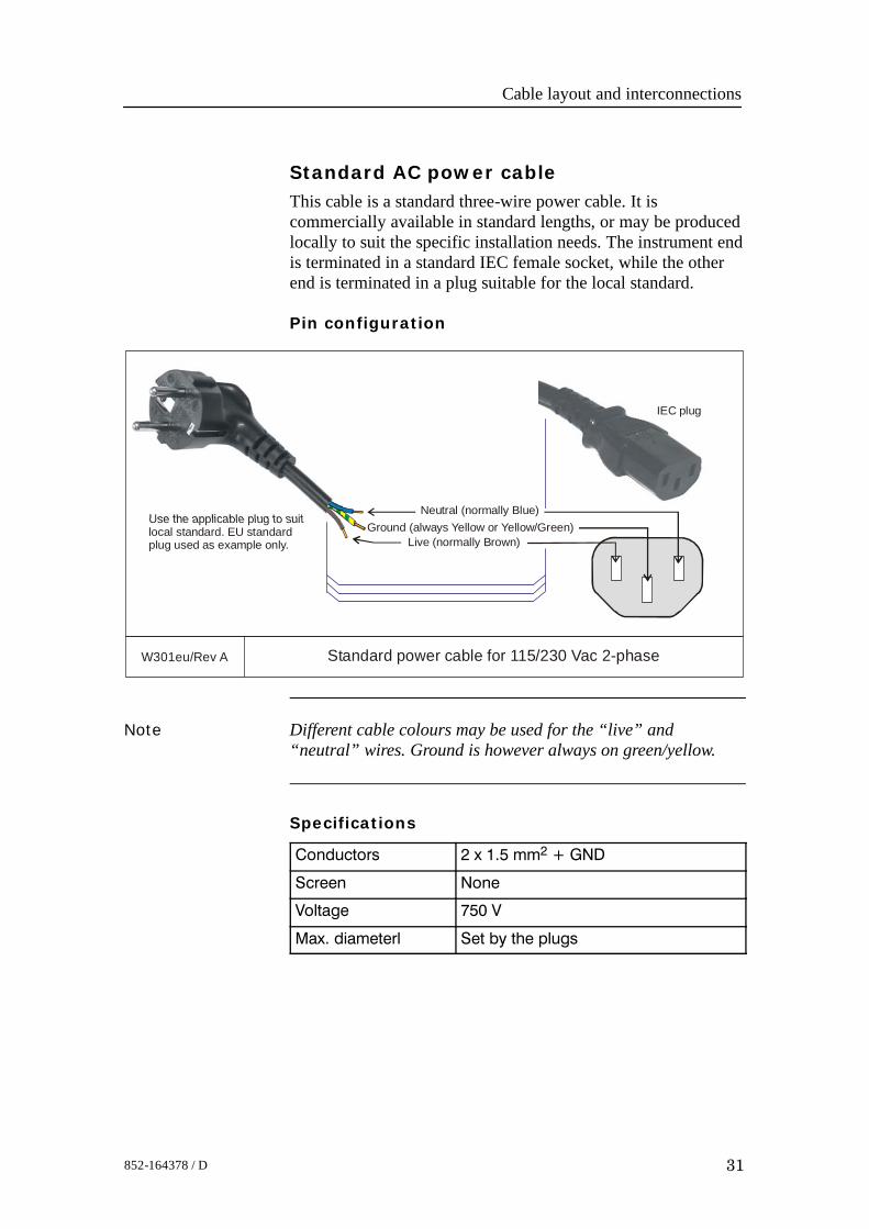
Standard AC power cableThis cable is a standard three-wire power cable. It iscommercially available in standard lengths, or may be producedlocally to suit the specific installation needs. The instrument endis terminated in a standard IEC female socket, while the otherend is terminated in a plug suitable for the local standard.
Pin configuration
W301eu/Rev A Standard power cable for 115/230 Vac 2-phase
Live (normally Brown)
Neutral (normally Blue)Use the applicable plug to suitlocal standard. EU standardplug used as example only.
Ground (always Yellow or Yellow/Green)
IEC plug
Note Different cable colours may be used for the “live” and“neutral” wires. Ground is however always on green/yellow.
Specifications
Conductors 2 x 1.5 mm2 + GND
Screen None
Voltage 750 V
Max. diameterl Set by the plugs
EM 2000 / Base version
32 852-164378 / D
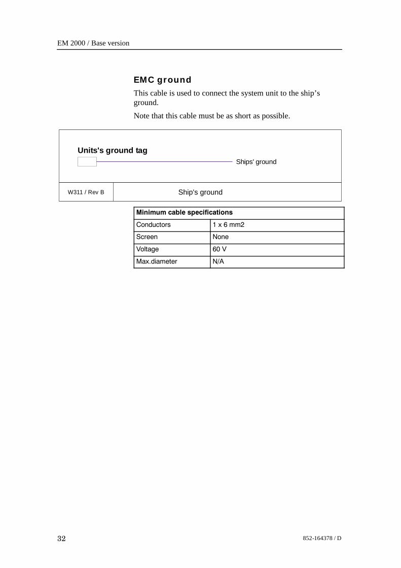
EMC groundThis cable is used to connect the system unit to the ship’sground.Note that this cable must be as short as possible.
W311 / Rev B Ship's ground
Units's ground tagShips' ground
Minimum cable specifications
Conductors 1 x 6 mm2
Screen None
Voltage 60 V
Max.diameter N/A
Cable layout and interconnections
33852-164378 / D
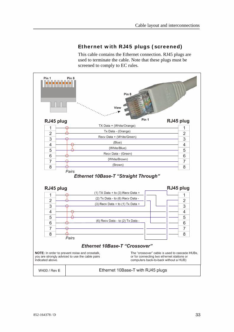
Ethernet with RJ45 plugs (screened)This cable contains the Ethernet connection. RJ45 plugs areused to terminate the cable. Note that these plugs must bescreened to comply to EC rules.
EM 2000 / Base version
34 852-164378 / D
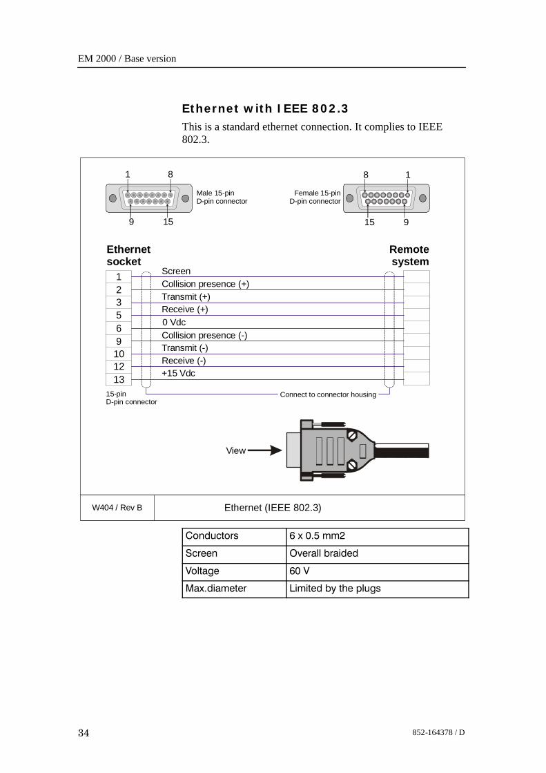
Ethernet with IEEE 802.3This is a standard ethernet connection. It complies to IEEE802.3.
W404 / Rev B Ethernet (IEEE 802.3)
123569101213
Ethernetsocket
Remotesystem
Collision presence (-)
Transmit (+)
Transmit (-)
Screen
Receive (+)
Receive (-)+15 Vdc
Collision presence (+)
0 Vdc
Connect to connector housing15-pinD-pin connector
Female 15-pinD-pin connector
Male 15-pinD-pin connector
1 8
159
8 1
915
View
Conductors 6 x 0.5 mm2
Screen Overall braided
Voltage 60 V
Max.diameter Limited by the plugs
Cable layout and interconnections
35852-164378 / D
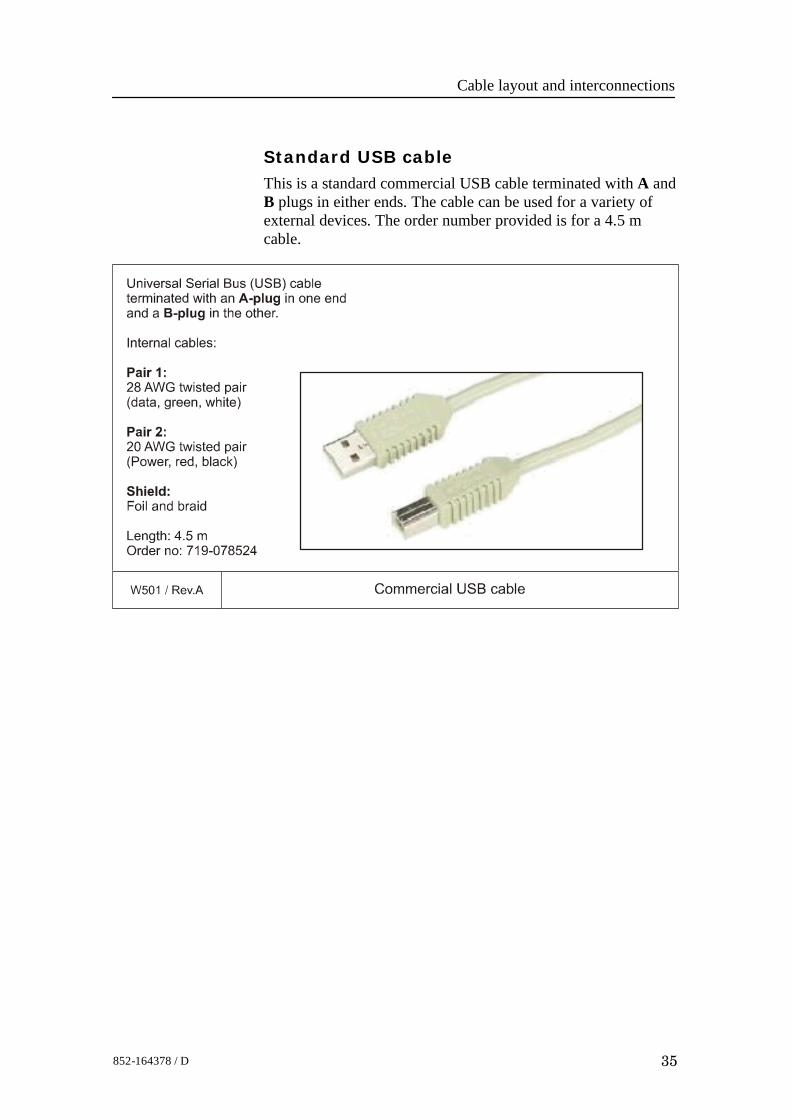
Standard USB cableThis is a standard commercial USB cable terminated with A andB plugs in either ends. The cable can be used for a variety ofexternal devices. The order number provided is for a 4.5 mcable.
EM 2000 / Base version
36 852-164378 / D
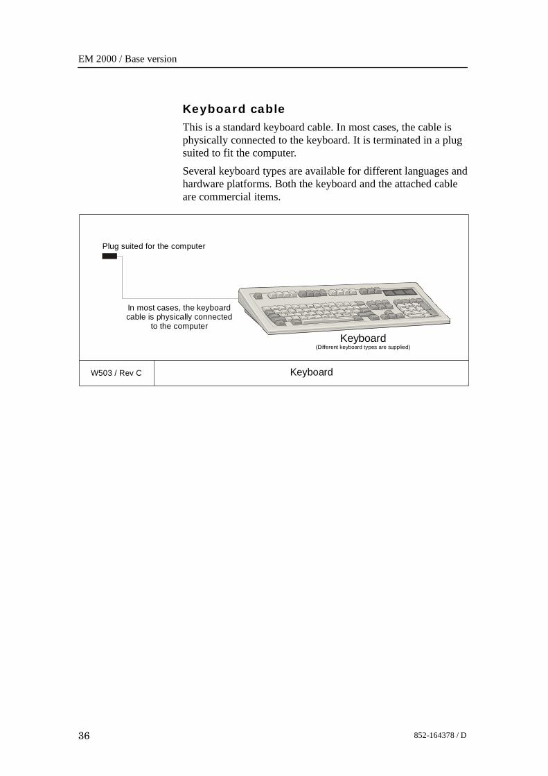
Keyboard cableThis is a standard keyboard cable. In most cases, the cable isphysically connected to the keyboard. It is terminated in a plugsuited to fit the computer.Several keyboard types are available for different languages andhardware platforms. Both the keyboard and the attached cableare commercial items.
W503 / Rev C Keyboard
Keyboard(Different keyboard types are supplied)
In most cases, the keyboardcable is physically connected
to the computer
Plug suited for the computer
Cable layout and interconnections
37852-164378 / D
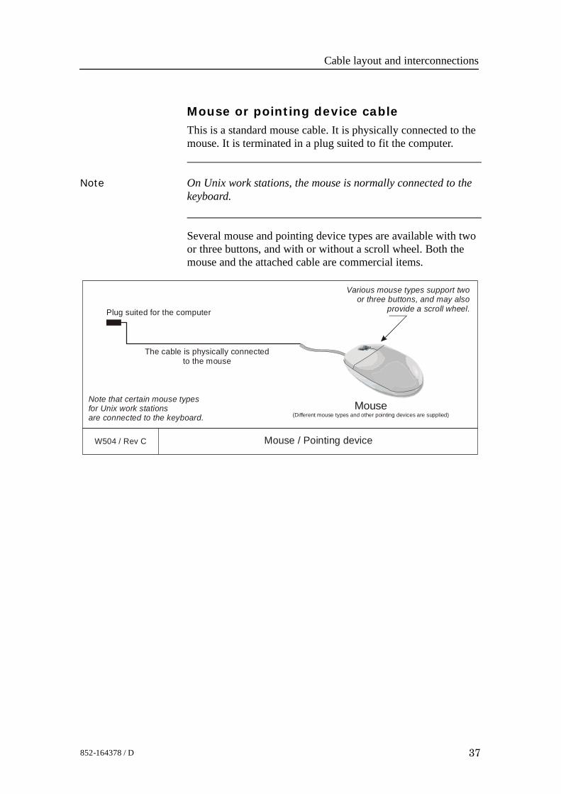
Mouse or pointing device cableThis is a standard mouse cable. It is physically connected to themouse. It is terminated in a plug suited to fit the computer.
Note On Unix work stations, the mouse is normally connected to thekeyboard.
Several mouse and pointing device types are available with twoor three buttons, and with or without a scroll wheel. Both themouse and the attached cable are commercial items.
W504 / Rev C Mouse / Pointing device
Mouse(Different mouse types and other pointing devices are supplied)
The cable is physically connectedto the mouse
Plug suited for the computer
Note that certain mouse typesfor Unix work stationsare connected to the keyboard.
Various mouse types support twoor three buttons, and may also
provide a scroll wheel.
EM 2000 / Base version
38 852-164378 / D
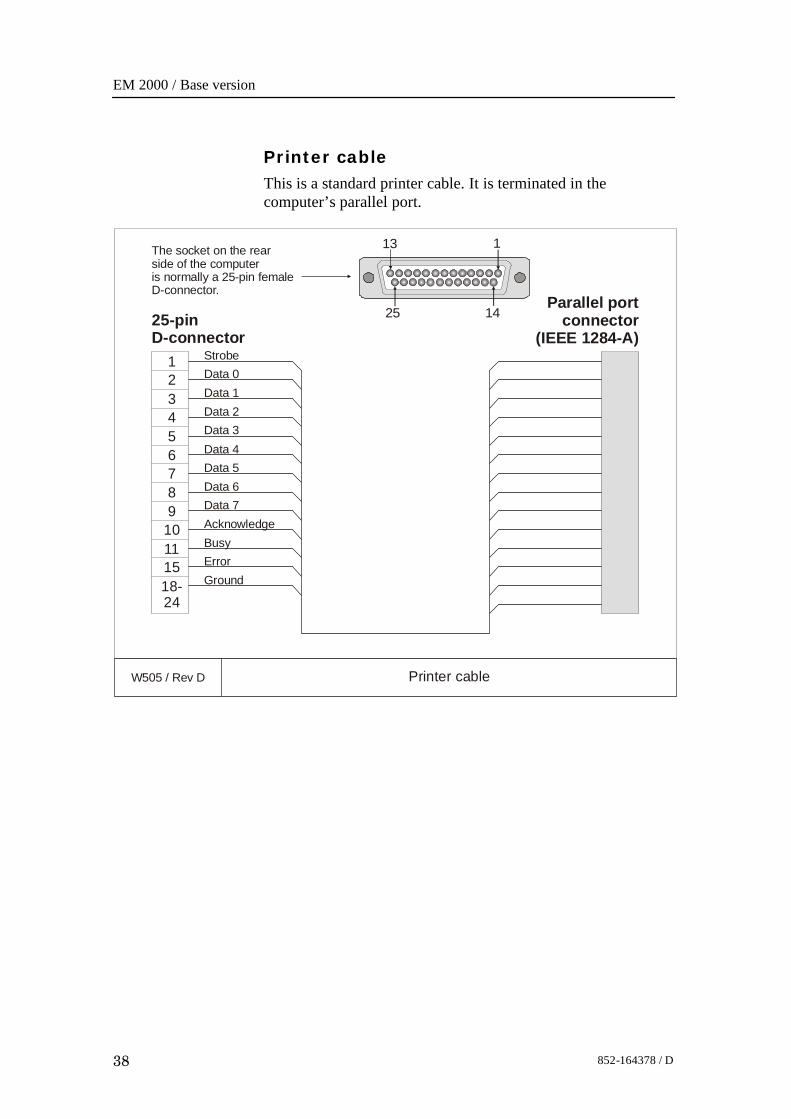
Printer cableThis is a standard printer cable. It is terminated in thecomputer’s parallel port.
W505 / Rev D Printer cable
1
32
45
76
89
1110
1518-24
StrobeData 0Data 1Data 2Data 3Data 4Data 5Data 6Data 7AcknowledgeBusyErrorGround
Parallel portconnector
(IEEE 1284-A)25-pinD-connector
25 14
113The socket on the rearside of the computeris normally a 25-pin femaleD-connector.
Cable layout and interconnections
39852-164378 / D
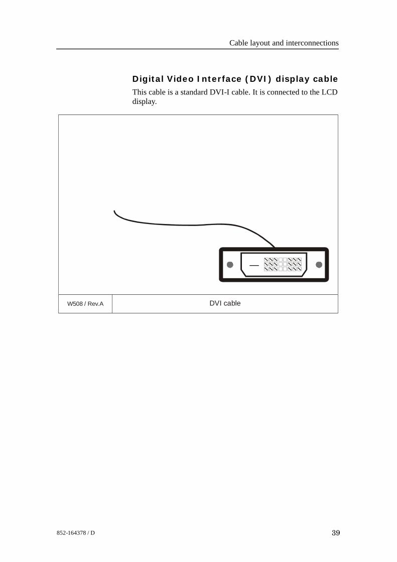
Digital Video Interface (DVI) display cableThis cable is a standard DVI-I cable. It is connected to the LCDdisplay.
W508 / Rev.A DVI cable
EM 2000 / Base version
40 852-164378 / D
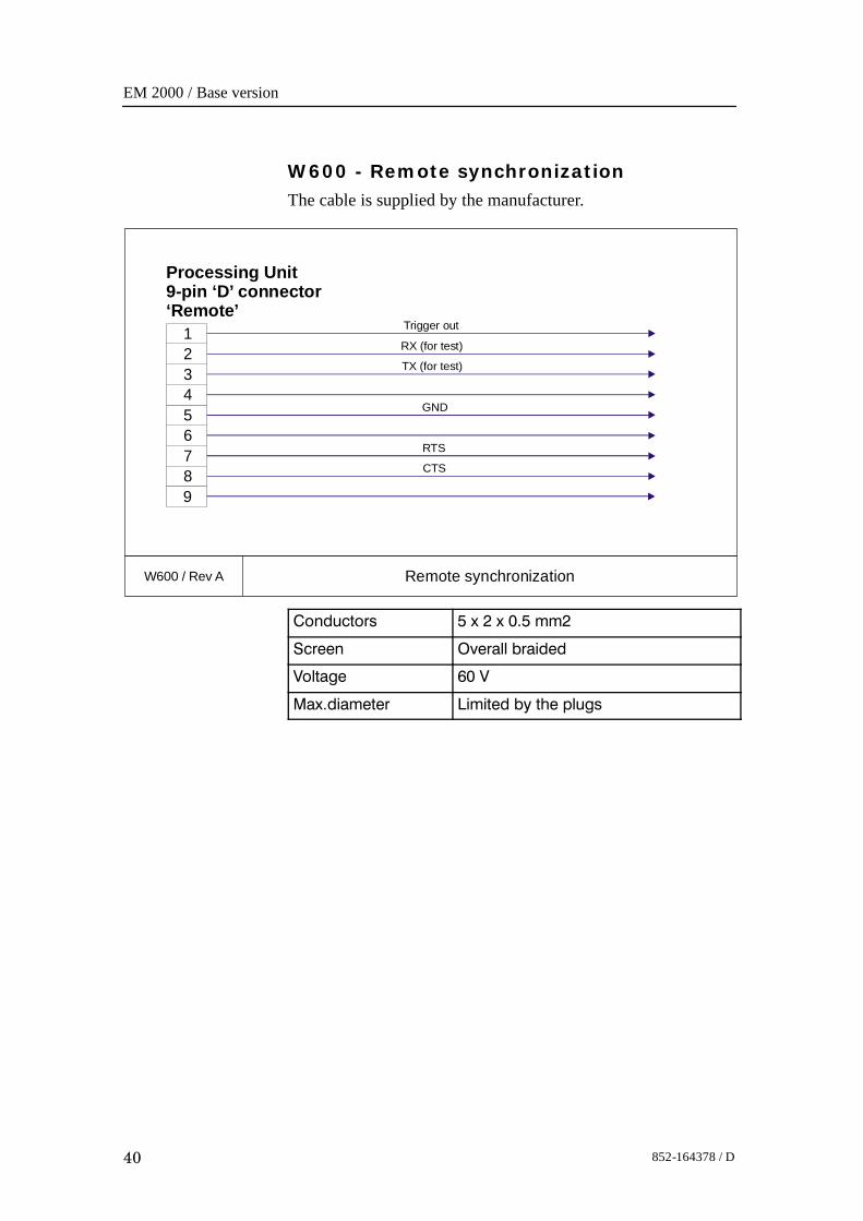
W600 - Remote synchronizationThe cable is supplied by the manufacturer.
W600 / Rev A Remote synchronization
9
1
32
45
76
8
Trigger out
RX (for test)
TX (for test)
RTS
CTS
GND
Processing Unit9-pin ‘D’ connector‘Remote’
Conductors 5 x 2 x 0.5 mm2
Screen Overall braided
Voltage 60 V
Max.diameter Limited by the plugs

Cable layout and interconnections
41852-164378 / D
W807 - Sonar Head cableThis is the cable from the EM 2000 Processing Unit to theSonar Head. The cable is supplied by the manufacturer.
W807 / Rev E Sonar Head
5
4
3
2
1
6
1
1
1 4
2
2
2 5
3
8
5
3
9
4
2
7
6
6
1
P2 - Green socket
Taxi (+)Taxi (-)
+24 VdcGND
GNDRef
Serial linkSerial link
P3
P1 - Red socket
Processing UnitP1 / P2 / P3
Sonar HeadWatertight connector
View: Seen into the plug.
10
810
3 1

EM 2000 / Base version
42 852-164378 / D
3.6 Sonar Head cable drawings
Figure 7 Sonar Head cable, assembly drawing
Approx 550 mm
Approx 60 mm
7 m
m
7 m
m
Plug FFA.1S.250CTAC52Z-COMP(370-086959)
Plug 6-pin EGG.2B.306CNAD99-COMP
(370-086957)
1
2
3
4
5
6
In-line UV plug
UV cable12-6621 Pur orange(642-086803)
Length15 m
Heat-shrinkable sleeve
Heat-shrinkable sleeve
CableRCOP60V4x(2x0.5)
Protection capGMA.1B.045.DV379-086961
Protection capGMA.1B.045.DR379-086962
Dismantling the coax cables
(CD
2141
3)
350 mm 350 mm
300 mm
View:Seen from solder side.
Cable layout and interconnections
43852-164378 / D
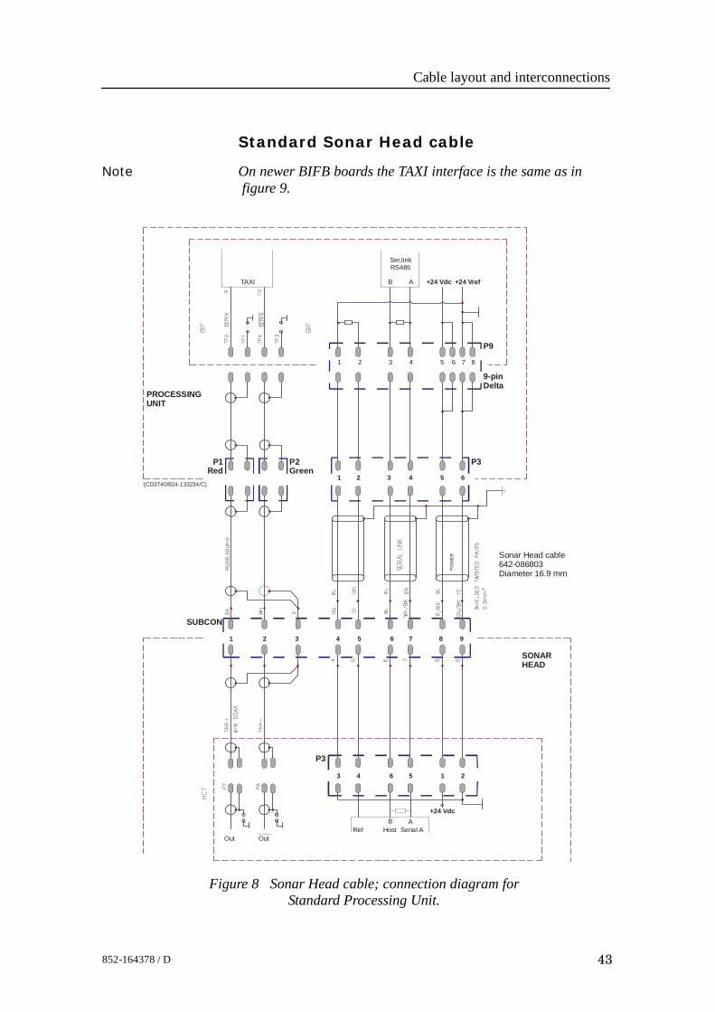
Standard Sonar Head cable
Note On newer BIFB boards the TAXI interface is the same as infigure 9.
Figure 8 Sonar Head cable; connection diagram forStandard Processing Unit.
TAXI B A +24 Vdc
+24 Vdc
+24 Vref
Ser.linkRS485
1
1
1
6
2
2
2
5
3
3
3
3
4
4
4
4
5
5
5
6
6
6
7 8
P3P2Green
P1Red
7 8 9
21
SONARHEAD
PROCESSINGUNIT
Sonar Head cable642-086803Diameter 16.9 mm
(CD3740/824-133234/C)
P9
9-pinDelta
SUBCON
P3
POW
ER
OutHost Serial A
B ARef
Out
EM 2000 / Base version
44 852-164378 / D
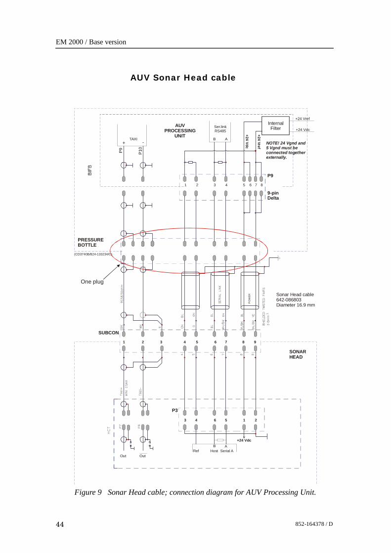
AUV Sonar Head cable
Figure 9 Sonar Head cable; connection diagram for AUV Processing Unit.
TAXI B A
+24 Vdc
Ser.linkRS485
1
1
6
2
2
5
3
3
3
4
4
4
5
5
6
6
7 8
7 8 9
21
SONARHEAD
AUVPROCESSING
UNIT
Sonar Head cable642-086803Diameter 16.9 mm
(CD3740B/824-133234/C)
P9
9-pinDelta
SUBCON
P3
PO
WE
R
OutHost Serial A
B ARef
Out
One plug
PRESSURE BOTTLE
+24 Vdc
+24 Vref
InternalFilter +24 Vdc
+24 Vref
NOTE! 24 Vgnd and 5 Vgnd must be connected togetherexternally.
+ -
P9 P10
Cable layout and interconnections
45852-164378 / D
3.7 Sonar Head Connection
Sonar Head cableThe standard Sonar Head cable delivered by KongsbergMaritime has three plugs for connection to the standardProcessing Unit. These plugs must be substituted by oneunderwater plug with minimum 10 pins.A 4 meter cable without connectors in the “Processing Unitend” is available from Kongsberg Maritime.This can be ordered on registration number:• 380-212985.
Internal wiring inside the bottleCabling from the underwater plug to the AUV Processing UnitBIFB board:• Two mini coax cables must be used for the TAXI high speed
up-link.• A multi wire cable must be used to connect 24 V, RS485
serial line.Plug and cable specifications (not supplied by KongsbergMaritime):• 2 mini coax connectors to plug into the BIFB board.• 2 mini coax cable for the TAXI link.• Plug for power and serial link for connection to the BIFB
board: standard 9 pins delta plug.
- Minimums cable dimensions: 0.5 mm2.→ For more details, refer to drawing on page NO TAG.
EM 2000 / Base version
46 852-164378 / D
3.8 Basic cabling requirements
Cable trays
All permanently installed cables associated with the systemmust be supported and protected along their entire lengths usingconduits and/or cable trays. The only exception to this rule isover the final short distance (max. 0.5 metre) as the cables runinto the cabinets/units to which they are connected. These shortservice loops are to allow the cabinets to move on their shockmounts, and to allow maintenance and repair.
• Wherever possible, cable trays must be straight, accessibleand placed so as to avoid possible contamination bycondensation and dripping liquids (oil, etc.). They must beinstalled away from sources of heat, and must be protectedagainst physical damage. Suitable shields must be providedwhere cables are installed in the vicinity of heat sources.
• Unless it is absolutely unavoidable, cables should not beinstalled across the vessel’s expansion joints. If the situationis unavoidable, a loop of cable having a length proportionalto the possible expansion of the joint must be provided. Theminimum internal radius of the loop must be at least twelvetimes the external diameter of the cable.
• Where a service requires duplicate supply lines, the cablesmust follow separate paths through the vessel wheneverpossible.
• Signal cables must not be installed in the same cable tray orconduit as high-power cables.
• Cables containing insulation materials with differentmaximum-rated conductor temperatures should not bebunched together (that is, in a common clip, gland, conduit orduct). When this is impractical, the cables must be carefullyarranged such that the maximum temperature expected in anycable in the group is within the specifications of thelowest-rated cable.
• Cables with protective coverings which may damage othercables should not be grouped with other cables.
• Cables having a copper sheath or braiding must be installedin such a way that galvanic corrosion by contact with othermetals is prevented.
• To allow for future expansion of the system, all cables shouldbe allocated spare conductor pairs. Also, space within thevessel should be set aside for the installation of extra cables.
Cable layout and interconnections
47852-164378 / D
Radio Frequency interference
All cables that are to be permanently installed within 9 m(30 ft) of any source of Radio Frequency (RF) interference suchas a transmitter aerial system or radio transmitters, must, unlessshielded by a metal deck or bulkhead, be adequately screened bysheathing, braiding or other suitable material. In such a situationflexible cables should be screened wherever possible.
It is important that cables, other than those supplying services tothe equipment installed in a radio room, are not installedthrough a radio room, high power switch gear or other potentialsources of interference. Cables which must pass through a radioroom must be screened by a continuous metal conduit ortrunking which must be bonded to the screening of the radioroom at its points of entry and exit.
Physical protection
Cables exposed to the risk of physical damage must be enclosedin a steel conduit or protected by a metal casing unless thecable’s covering (e.g. armour or sheath) is sufficient to protect itfrom the damage risk.
Cables exposed to an exceptional risk of mechanical damage(for example in holds, storage-spaces and cargo-spaces) must beprotected by a suitable casing or conduit, even when armoured,if the cable covering does not guarantee sufficient protection forthe cables.
Metallic materials used for the physical protection of cablesmust be suitably protected against corrosion.
Grounding
All metallic cable coverings (armour, metallic sheathing etc.)must be electrically connected to the vessel’s hull at both endsexcept in the case of final sub-circuits where they should beconnected at the supply end only.
Grounding connections should be made using a conductor whichhas a cross-sectional area appropriate for the current rating ofthe cable, or with a metal clamp which grips the metalliccovering of the cable and is bonded to the hull of the vessel.These cable coverings may also be grounded by means of glandsspecially intended for this purpose and designed to ensure agood ground connection. The glands used must be firmlyattached to, and in good electrical contact with, a metal structuregrounded in accordance with these recommendations.
EM 2000 / Base version
48 852-164378 / D
Electrical continuity must be ensured along the entire length ofall cable coverings, particularly at joints and splices. In no caseshould the shielding of cables be used as the only means ofgrounding cables or units.Metallic casings, pipes and conduits must be grounded, andwhen fitted with joints these must be mechanically andelectrically grounded locally.
Cable connections
All cable connections are shown on the applicable cable planand interconnection diagrams.Where the cable plan shows cable connections outside anequipment box outline, the connections are to be made to a plugor socket which matches the plug or socket on that particularitem of equipment.Where two cables are connected in series via a junction box orterminal block, the screens of both cables must be connectedtogether but not grounded.
Cable terminations
Care must be taken to ensure that the correct terminations areused for all cable conductors, especially those that are to beconnected to terminal blocks. In this case, crimpedsleeve-terminations must be fitted to prevent the conductor corefrom fraying and making a bad connection with the terminalblock. It is also of the utmost importance that where crimpedterminations are used, the correct size of crimp and crimpingtool are used. In addition, each cable conductor must have aminimum of 15 cm slack (service loop) left before itstermination is fitted.
Cable identification
Cable identification codes corresponding to the cable numbershown in the cable plan must be attached to each of the externalcables. These identification codes should be positioned on thecable in such a way that they are readily visible after all panelshave been fitted. In addition, each cable conductor should bemarked with the terminal board number or socket to which it isconnected.
Operator Station
49852-164378 / D
4 OPERATOR STATION
4.1 Description and main functions
IntroductionThe HWS 10 Hydrographic Work Station is the Operator Stationnormally used by the EM 2000.
Topic
→ HWS 10 outline drawing, page 50→ Theory of operation, page 51→ Installation, page 52
EM 2000 / Base version
50 852-164378 / D
-Rev.A
Page 1 of 1(CD25000)
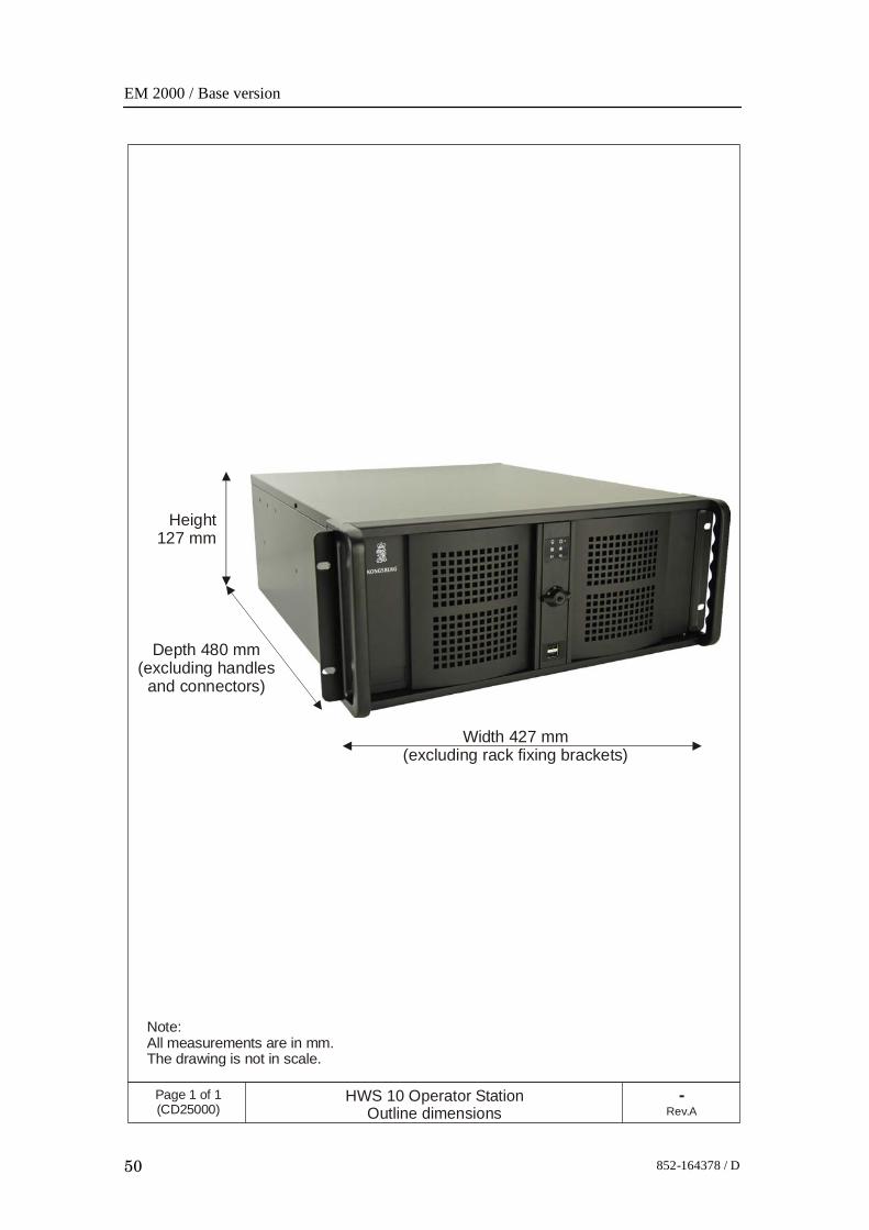
HWS 10 Operator StationOutline dimensions
Note:All measurements are in mm.The drawing is not in scale.
Width 427 mm (excluding rack fixing brackets)
Height 127 mm
Depth 480 mm (excluding handles
and connectors)
Operator Station
51852-164378 / D
4.2 Theory
OverviewThe HWS 10 is equipped to handle the heavy processingrequirements and high-speed, largevolume data storage demandsof today’s hydrographic systems. It has been specificallydesigned as the optimal platform for running the SeafloorInformation System (SIS) real-time operating software used onthe Kongsberg EM multibeam echo sounders. Special featuresof SIS include real-time:• Gridding of sounding data.• Filtering of sounding data.• 3-D visualization of sounding data.• Storage and visualization of high resolution backscatter data
from the seabed and the water column.
SoftwareThe partitioned system disk is dual bootable with Linux® andMicrosoft Windows XP® respectively. SIS software is factoryinstalled and tested on both operating systems.
Data storageThe primary task of the HWS 10 is to safeguard the collecteddata and to visualize it for quality control. All data is initiallystored on a pair of high performance SerialATA disks. Thesedisks are run in a RAID1 configuration, thus ensuring againstloss of data even if one disk should fail. They are mounted inhot swappable enclosures, so that the collected data may betransported on the disk. A DVD recorder is the standard meansfor permanent archiving of the collected data. For users havingpreferences for other storage devices or media, the HWS 10includes USB 2.0, Firewire (IEEE 1394) and SCSI interfaces.Gigabit Ethernet is available for transfer of the data to anothernetwork computer. For temporary storage data may also bebacked up to the system drive.
EM 2000 / Base version
52 852-164378 / D
4.3 InstallationThe HWS 10 is prepared for mounting in a 19” rack. Thesystem’s 17.4” Industrial LCD monitor is also rack mountable,and a universal bracket is supplied for tabletop, overhead orbulkhead mounting. Both the workstation and the monitor areIP22 rated. A spill-proof US keyboard and a standard opticalmouse is included, but a small IP65 keyboard with integratedtrack stick is optionally available. A 5.25” externally accessibledrive bay is available for customer use. The system supports theuse of a second LCD monitor, this may be a 15” unit for use as ahelmsman display.
Note The IP22 rating requires that the two front USB ports (of a totalof six) are covered. If the IP22 rating is not required, and thetwo front USB ports are needed, this cover may be removed.
Processing Unit
53852-164378 / D
5 PROCESSING UNIT
5.1 IntroductionThe EM 2000 Processing Unit performs the data acquisition,signal processing and function control.
Topics
→ Standard Processing Unit drawing, page 54.→ AUV Processing Unit drawing, page 55.→ Circuit boards and modules, page 56.→ AUV Processing Unit Circuit boards and modules, page 57.→ Theory of operation, page 59.→ Standard Processing Unit details, page 63.→ AUV Processing Units details, page 64.→ Circuit board descriptions, page 65.→ Serial Line board (CI-104JS), page 66.→ 4-Ports Serial Line Board (C114P), page 68.→ Cool Monster C/400 Control Processor Board, page 71.→ VIPer 629 Control Processor Board, page 70.→ Beamformer and Signal Processor (BSP), page 73.→ Beamformer Interface Board (BIFB), page 76.→ Passive Backplane BP-10S, page 78.→ Processing Unit Power Supply, page 80.→ Assambly backplane, page 81.
EM 2000 / Base version
54 852-164378 / D
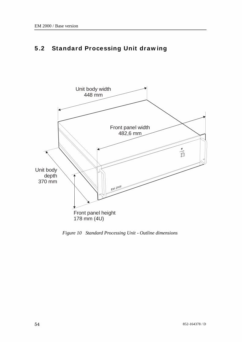
5.2 Standard Processing Unit drawing
Figure 10 Standard Processing Unit - Outline dimensions
Unit body width448 mm
Unit bodydepth
370 mm
Front panel width482,6 mm
Front panel height178 mm (4U)

Processing Unit
55852-164378 / D
5.3 AUV Processing Unit drawing
Figure 11 AUV Processing Unit - Outline dimensions(shown with Fan Unit and cover).
50.8 50.8192.4
FanU
nit
421
SERIAL PORT 3
1PPS
SERIAL PORT 2
139.7124
Chassis shown with top cover, mounted in tube.
~170
182
ø235
Min.ø220
(CD
6429
b/83
4-21
6073
a)
EM 2000 / Base version
56 852-164378 / D
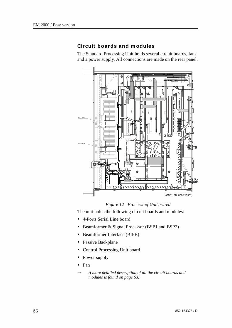
Circuit boards and modulesThe Standard Processing Unit holds several circuit boards, fansand a power supply. All connections are made on the rear panel.
Figure 12 Processing Unit, wired
HULL NO 17
HULL NO 28BI
F
BSP
I
BSP
II
SON AR HEAD
SO
NA
R
HE
AD
1
1
2
2
(CD6113B /860-213901)
CPU
Dis
k O
n M
odul
e
1 2 3 41 2 3 4
3
3
RAM
The unit holds the following circuit boards and modules:• 4-Ports Serial Line board• Beamformer & Signal Processor (BSP1 and BSP2)• Beamformer Interface (BIFB)• Passive Backplane• Control Processing Unit board• Power supply• Fan→ A more detailed description of all the circuit boards and
modules is found on page 63.
Processing Unit
57852-164378 / D
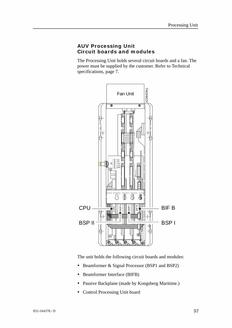
AUV Processing UnitCircuit boards and modules
The Processing Unit holds several circuit boards and a fan. Thepower must be supplied by the customer. Refer to Technicalspecifications, page 7.
CPU
BSP
II
BSP
I
BIF
B
Fan Unit
+5V
J5 -5V-12V+12VGND
CPU
BSP IBSP II
BIF B
(CD
6429
c)
The unit holds the following circuit boards and modules:
• Beamformer & Signal Processor (BSP1 and BSP2)
• Beamformer Interface (BIFB)
• Passive Backplane (made by Kongsberg Maritime.)
• Control Processing Unit board

EM 2000 / Base version
58 852-164378 / D
Optional:• External harddiskPower for external hard disk must be supplied by the customer.The fan is supplied internally by 5 Vdc.The fan is suppliedinternally by 5Vdc.
Processing Unit
59852-164378 / D
5.4 Theory of operation
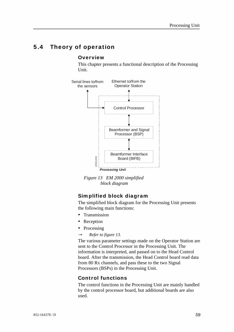
OverviewThis chapter presents a functional description of the ProcessingUnit.
Figure 13 EM 2000 simplifiedblock diagram
Control Processor
Beamformer and SignalProcessor (BSP)
Serial lines to/fromthe sensors
Ethernet to/from theOperator Station
Processing Unit
(CD
2141
0)
Beamformer InterfaceBoard (BIFB)
Simplified block diagramThe simplified block diagram for the Processing Unit presentsthe following main functions:• Transmission• Reception• Processing→ Refer to figure 13.The various parameter settings made on the Operator Station aresent to the Control Processor in the Processing Unit. Theinformation is interpreted, and passed on to the Head Controlboard. After the transmission, the Head Control board read datafrom 80 Rx channels, and pass these to the two SignalProcessors (BSPs) in the Processing Unit.
Control functionsThe control functions in the Processing Unit are mainly handledby the control processor board, but additional boards are alsoused.
EM 2000 / Base version
60 852-164378 / D
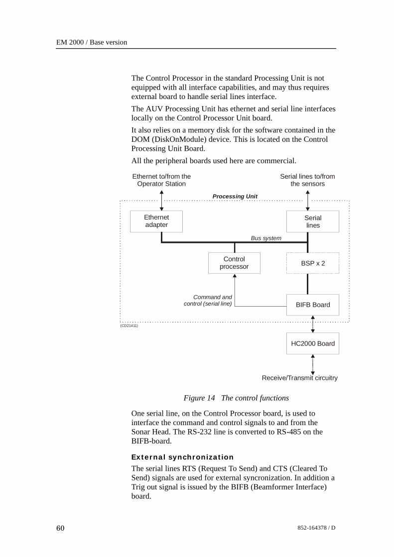
The Control Processor in the standard Processing Unit is notequipped with all interface capabilities, and may thus requiresexternal board to handle serial lines interface.The AUV Processing Unit has ethernet and serial line interfaceslocally on the Control Processor Unit board.It also relies on a memory disk for the software contained in theDOM (DiskOnModule) device. This is located on the ControlProcessing Unit Board.All the peripheral boards used here are commercial.
Figure 14 The control functions
Seriallines
Controlprocessor
Ethernetadapter
BSP x 2
Serial lines to/fromthe sensors
Ethernet to/from theOperator Station
Command andcontrol (serial line)
Processing Unit
Bus system
(CD21411)
HC2000 Board
Receive/Transmit circuitry
BIFB Board
One serial line, on the Control Processor board, is used tointerface the command and control signals to and from theSonar Head. The RS-232 line is converted to RS-485 on theBIFB-board.
External synchronization
The serial lines RTS (Request To Send) and CTS (Cleared ToSend) signals are used for external syncronization. In addition aTrig out signal is issued by the BIFB (Beamformer Interface)board.
Processing Unit
61852-164378 / D
Levels
RTS, CTS = high +3 to +15 V
RTS, CTS = low --3 to --15 V
Trig out TTL level
Outputs from PU
Trig out = 1 TX is off (high TTL level)
Trig out = 0 TX is active (low TTL level)
RTS = high PU is ready for a new ping
RTS = low PU is not ready
RTS is pin 7
Inputs to PU
CTS = high Ping command
CTS = low Wait
CTS is pin 8 The CTS pulse length must be minimum30 milliseconds
GND (ground) is pin 5
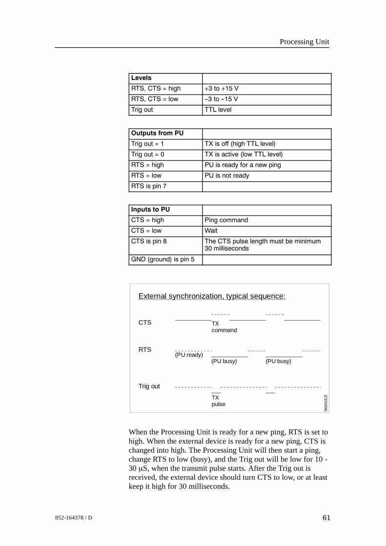
External synchronization, typical sequence:
CTS TXcommand
RTS
Trig out
(PU ready)(PU busy)
TXpulse
(PU busy)
(CD
5958)
When the Processing Unit is ready for a new ping, RTS is set tohigh. When the external device is ready for a new ping, CTS ischanged into high. The Processing Unit will then start a ping,change RTS to low (busy), and the Trig out will be low for 10 -30 μS, when the transmit pulse starts. After the Trig out isreceived, the external device should turn CTS to low, or at leastkeep it high for 30 milliseconds.
EM 2000 / Base version
62 852-164378 / D
When the received period is finished and the Processing Unit isready for a new ping, the RTS will be changed to high, and theProcessing Unit will wait for a new trigger (a high level onCTS).If CTS is high at all times, or if external synchronization in theinstallation menu is switched off, the Processing Unit will pingat its maximum rate.
1PPS
The 1PPS input signal is normally “resting” at a high level.Each second, a pulse (100μS-1000μS) adjusts the secondcounter in the Processing Unit. Since 1PPS is a TTL-signal, ahigh level at the input connector must be higher than 2,7 Vdc(margin is 0.3 Vdc) and a low level (during the pulse) must notexeed 0.6 Vdc (margin is 0.2 Vdc).
Processing Unit
63852-164378 / D
5.5 Standard Processing Unit detailsThe Processing Unit holds several circuit boards, fans and apower supply.
Circuit boards and modules
4-ports Serial Line Board
This is a commercial circuit board. It provides the ProcessingUnit with four serial lines.→ The interface board, CI-104JS, is explained on page 66.→ The interface board, C114P, is explained on page 68.
Note Some of the systems delivered use the board C114P, while othersuse the board CI-104JS.
Beamformer & Signal Processor 1,2 (BSP1 andBSP2)
These are the main processing boards in the Processing Unit.→ The circuit board is explained on page 73.
Beamformer Interface (BIFB)
This is a Kongsberg Maritime made circuit board. It containsinterfaces for the sonar head. It is a single slot half-length ISAboard.→ The circuit board is explained on page 76.
Control Processor Unit Board (CPU), Viper
This processor board acts as a function controller. It holds aDiskOnModule flash disk and a ethernet adapter.→ The circuit board is explained on page 70.
Passive Backplane
This is a commercial backplane. It has a 10-slot ISA bus.→ The circuit board is explained on page 78
Power supply
The Processing Unit contains a commercial switch-mode powersupply located behind the circuit board.→ Refer to page 80
Fans
Two of the fans are located at the bottom of the Processing Unit.One is located next to the power supply.
EM 2000 / Base version
64 852-164378 / D
5.6 AUV Processing Unit details
Control Processor Unit Board (CPU), CoolMonster
This processor board acts as a function controller. It holds aDiskOnModule flash disk and a ethernet adapter and serial lines.→ The circuit board is explained on page 71
Beamformer & Signal Processor 1,2 (BSP1 andBSP2)
These are the main processing boards in the Processing Unit.→ The circuit board is explained on page 73.
Beamformer Interface (BIFB)
This is a Kongsberg Maritime made circuit board. It containsinterfaces for the sonar head. It is a single slot half-length ISAboard.→ The circuit board is explained on page 76.
Passive Backplane
This is manufactured by Kongsberg Maritime. It has a 4-slotPISA bus.
Fans
The fan is located at the end of the Processing Unit.
Power
5Vdc and 24Vdc, must be supplied by the customer.
Processing Unit
65852-164378 / D
5.7 Circuit board descriptions
OverviewThis chapter describes all the circuit boards and modules in theEM 2000 Processing Unit. A functional description with a blockdiagram is provided, as well as the facilities provided formaintenance.
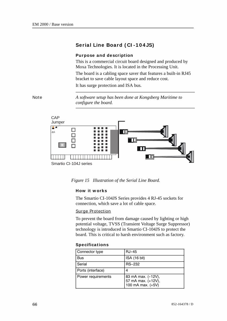
EM 2000 / Base version
66 852-164378 / D
Serial Line Board (CI-104JS)
Purpose and descriptionThis is a commercial circuit board designed and produced byMoxa Technologies. It is located in the Processing Unit.The board is a cabling space saver that features a built-in RJ45bracket to save cable layout space and reduce cost.It has surge protection and ISA bus.
Note A software setup has been done at Kongsberg Maritime toconfigure the board.
CAPJumper
Smartio CI-104J series
Jp1
Figure 15 Illustration of the Serial Line Board.
How it works
The Smartio CI-104JS Series provides 4 RJ-45 sockets forconnection, which save a lot of cable space.
Surge Protection
To prevent the board from damage caused by lighting or highpotential voltage, TVSS (Transient Voltage Surge Suppressor)technology is introduced in Smartio CI-104JS to protect theboard. This is critical to harsh environment such as factory.
Specifications
Connector type RJ--45
Bus ISA (16 bit)
Serial RS--232
Ports (interface) 4
Power requirements 83 mA max. (--12V),57 mA max. (+12V),100 mA max. (+5V)

Processing Unit
67852-164378 / D
Operating temperature 0_ -- 55_C
Dimensions 157 x 83 mm (width x depth)
Surge protection 25 KV ESD, 2 KV EFT
FacilitiesNo switches.
ReferencesFor more information, refer to webpage www.moxa.com.

EM 2000 / Base version
68 852-164378 / D
4-Ports Serial Line Board (C114P)
Purpose and descriptionThis is a commercial circuit board designed and produced byMoxa Technologies. This is identified as C114P, and is locatedin the Processing Unit.
P1
JP1 JP3 JP5 JP7
JP2 JP4 JP6 JP8
JP9
JP10
JP11
JP12
COM1
COM2
COM3
COM4
(CD5561)
Figure 16 The C114P layout
How it worksEach of the 4 ports can be configured to RS-232, RS-422, orRS-485 interface individually, but only RS-232 will work on theEM 2000 system.
Facilities
LEDsNone.JumpersThe C114 is set up with IRQ 11 on the jumpers JP9, JP10, JP11and JP12.Links
Note The following settings are only valid for new boards (version2). For elder boards (version 1) the settings will be inverted. Inthe table below, the settings that are OFF will be ON and viceversa.
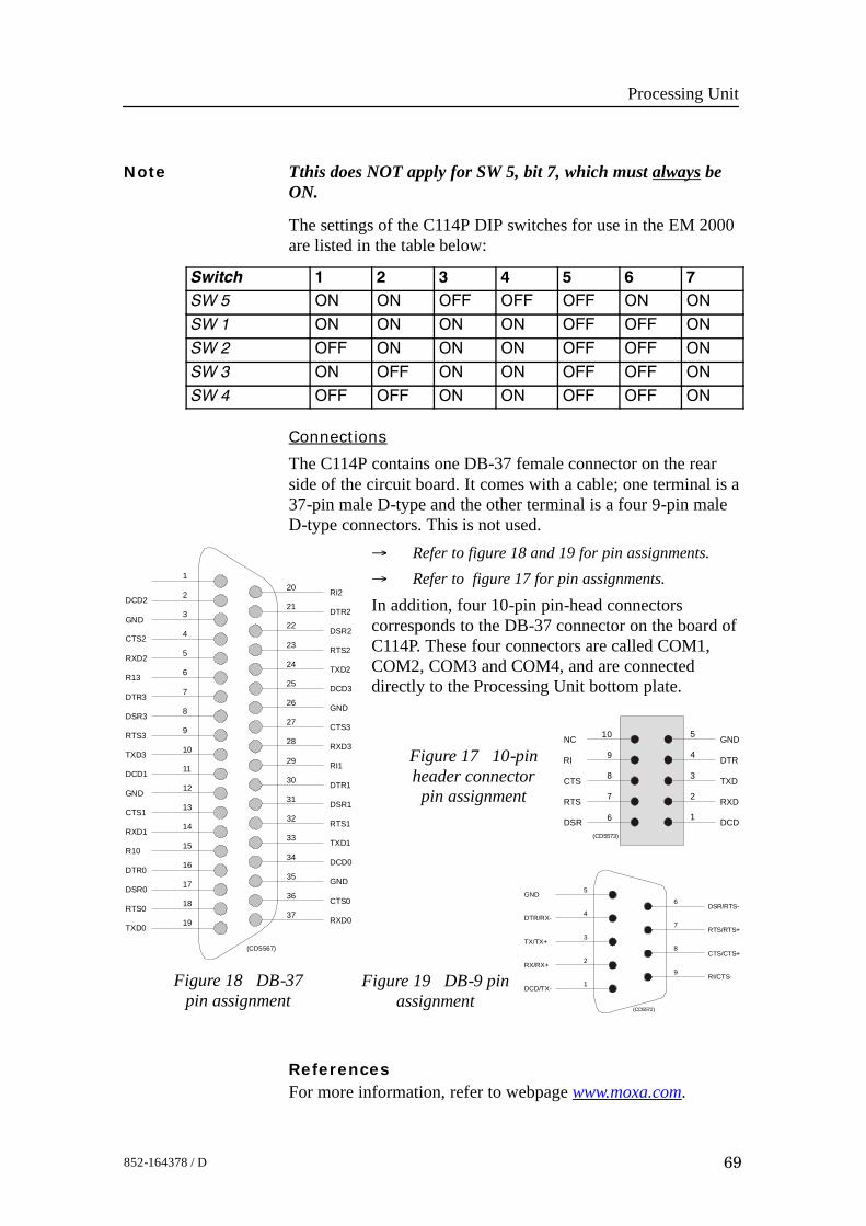
Processing Unit
69852-164378 / D
Note Tthis does NOT apply for SW 5, bit 7, which must always beON.
The settings of the C114P DIP switches for use in the EM 2000are listed in the table below:
Switch 1 2 3 4 5 6 7SW 5 ON ON OFF OFF OFF ON ON
SW 1 ON ON ON ON OFF OFF ON
SW 2 OFF ON ON ON OFF OFF ON
SW 3 ON OFF ON ON OFF OFF ON
SW 4 OFF OFF ON ON OFF OFF ON
Connections
The C114P contains one DB-37 female connector on the rearside of the circuit board. It comes with a cable; one terminal is a37-pin male D-type and the other terminal is a four 9-pin maleD-type connectors. This is not used.
→ Refer to figure 18 and 19 for pin assignments.→ Refer to figure 17 for pin assignments.
In addition, four 10-pin pin-head connectorscorresponds to the DB-37 connector on the board ofC114P. These four connectors are called COM1,COM2, COM3 and COM4, and are connecteddirectly to the Processing Unit bottom plate.
10
9
8
7
6
5
4
3
2
1
NC
RI
CTS
RTS
DSR
GND
DTR
TXD
RXD
DCD(CD5573)
Figure 17 10-pinheader connectorpin assignment
ReferencesFor more information, refer to webpage www.moxa.com.
1
2
3
4
5
6
7
8
9
10
11
12
13
14
15
16
17
18
19
20
21
22
23
24
25
26
27
28
29
30
31
32
33
34
35
36
37
DCD2
GND
CTS2
RXD2
R13
DTR3
DSR3
RTS3
TXD3
DCD1
GND
CTS1
RXD1
R10
DTR0
DSR0
RTS0
TXD0
RI2
DTR2
DSR2
RTS2
TXD2
DCD3
GND
CTS3
RXD3
RI1
DTR1
DSR1
RTS1
TXD1
DCD0
GND
CTS0
RXD0
(CD5567)
Figure 18 DB-37pin assignment
5
4
3
2
1
6
7
8
9
GND
DTR/RX-
TX/TX+
RX/RX+
DCD/TX-
DSR/RTS-
RTS/RTS+
CTS/CTS+
RI/CTS-
(CD5572)
Figure 19 DB-9 pinassignment
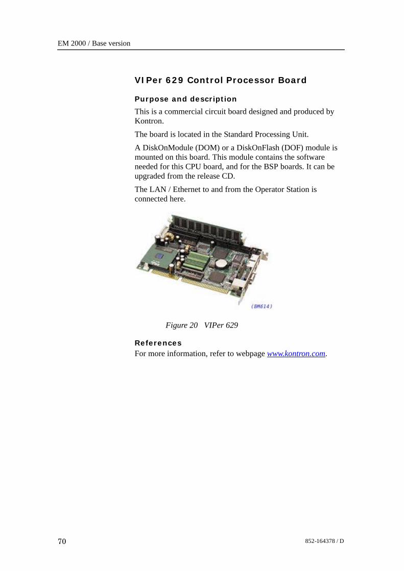
EM 2000 / Base version
70 852-164378 / D
VIPer 629 Control Processor Board
Purpose and description
This is a commercial circuit board designed and produced byKontron.The board is located in the Standard Processing Unit.A DiskOnModule (DOM) or a DiskOnFlash (DOF) module ismounted on this board. This module contains the softwareneeded for this CPU board, and for the BSP boards. It can beupgraded from the release CD.The LAN / Ethernet to and from the Operator Station isconnected here.
Figure 20 VIPer 629
ReferencesFor more information, refer to webpage www.kontron.com.
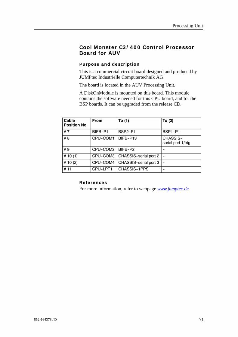
Processing Unit
71852-164378 / D
Cool Monster C3/400 Control ProcessorBoard for AUV
Purpose and description
This is a commercial circuit board designed and produced byJUMPtec Industrielle Computertechnik AG.The board is located in the AUV Processing Unit.A DiskOnModule is mounted on this board. This modulecontains the software needed for this CPU board, and for theBSP boards. It can be upgraded from the release CD.
CablePosition No.
From To (1) To (2)
# 7 BIFB--P1 BSP2--P1 BSP1--P1
# 8 CPU--COM1 BIFB--P13 CHASSIS--serial port 1/trig
# 9 CPU--COM2 BIFB--P2 --
# 10 (1) CPU--COM3 CHASSIS--serial port 2 --
# 10 (2) CPU--COM4 CHASSIS--serial port 3 --
# 11 CPU--LPT1 CHASSIS--1PPS --
ReferencesFor more information, refer to webpage www.jumptec.de.
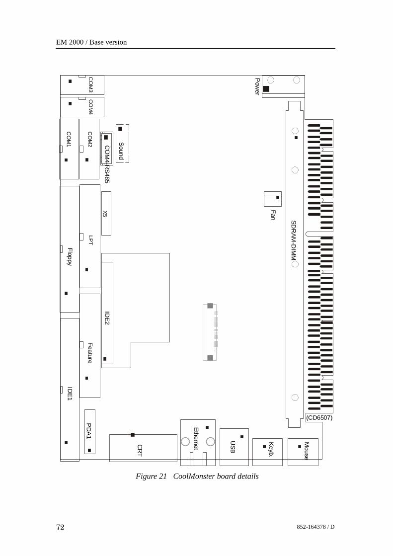
EM 2000 / Base version
72 852-164378 / D
Figure 21 CoolMonster board details
CO
M3
CO
M4
CO
M1
CO
M2 Sound
CO
M4-R
S485
Floppy
LPT
X5
Feature
IDE
1
IDE2
PD
A1
CR
T
USB
Ethernet
Keyb.
Mouse
Pow
er
Fan SDR
AM-D
IMM
(CD6507)

Processing Unit
73852-164378 / D
Beamformer & Signal Processor (BSP)
Purpose and description
The Beamforming & Signal Processing (BSP) board is a multidigital signal processor (DSP) board. It is designed to performthe beamforming and signal processing in sonars and multibeamecho sounders. It is controlled from a host processor.
The processing power in the Beamforming & Signal Processing(BSP) board is based on eight Texas TMS320C50 fixed pointdigital signal processors working in parallel while beamformingthe data. Next, there are four Texas TMS320C44 floating pointdigital signal processors interconnected to use both parallel andsequential processing of the beamformed data from the fixedpoint processors.
The Beamforming & Signal Processing (BSP) board is a singleslot full length standard ISA format circuit board made to fitinto a personal computer.
How it works
The Beamforming & Signal Processing (BSP) board containsfour main sections:
• Sonar Input Data
• Beamforming
• Signal Processing
• Host Interface
The Sonar Input Data interfaces an 18-bit wide and 1k deepInput FIFO (First-In-First-Out) register. This input FIFO holdsthe data received from the transducer array through the receiverprocessing circuitry. A dedicated digital signal processor readsthe input FIFO.
There are two identical Beamforming digital signal processingbranches. Each consists of four digital signal processors and a16-bit wide and 8k deep dual port memory (DPRAM). The twobranches are exchanging data by means of this DPRAM.
The Signal Processing section comprises three digital signalprocessors dedicated to do further processing of thebeamformed data.
The Host Interface function is maintained by the masterprocessor on the Beamforming & Signal Processing (BSP)board. It exchanges data with the host processor via a 16-bitwide and 8k deep dual port memory (DPRAM) on the ISA bus.

EM 2000 / Base version
74 852-164378 / D
Facilities
LEDs
D1 (LED): C44 D
Test points
There is one test point for each C50 digital signal processor(eight total). These testpoints are all connected to the XF/ signalwhich is active while that particular C50 access the sharedDPRAM.There is also one test point for each C44 digital signal processor(four total). These test points are connected to the IIOF2/ signal,which is a general purpose I/O port bit that can be controlled bythe software.The C44-D testpoint is also connected to a light emitting diode(D1) for visual observation. The LED will be activated duringeach ping.
TP1 C50 E0
TP2 C50 E1
TP3 C50 E2
TP4 C50 E3
TP5 C50 F0
TP6 C50 F1
TP7 C50 F2
TP8 C50 F3
TP11 C44 A
TP12 C44 B
TP13 C44 C
TP14 (& D1) C44 D
The testpoints will be active when the corresponding processoris working.
Links
A number of links are implemented on the board to allow forseveral different applications. Links LK1, LK2 and LK3 areused to identify the board as one out of maximum eight boardsin one system.
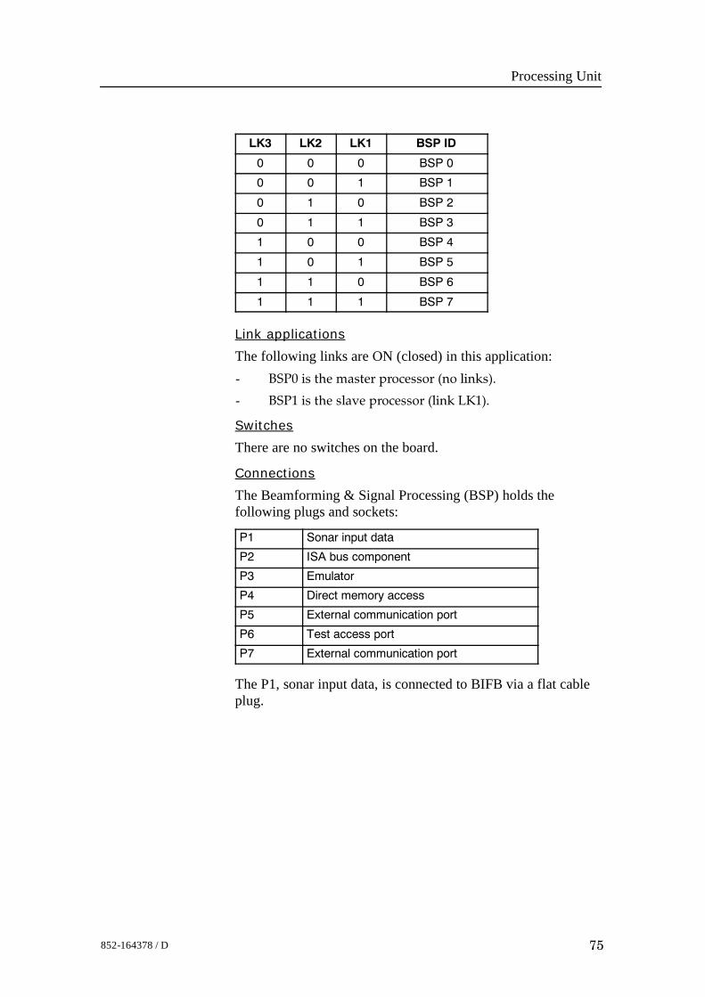
Processing Unit
75852-164378 / D
LK3 LK2 LK1 BSP ID
0 0 0 BSP 0
0 0 1 BSP 1
0 1 0 BSP 2
0 1 1 BSP 3
1 0 0 BSP 4
1 0 1 BSP 5
1 1 0 BSP 6
1 1 1 BSP 7
Link applications
The following links are ON (closed) in this application:- BSP0 is the master processor (no links).
- BSP1 is the slave processor (link LK1).
Switches
There are no switches on the board.
Connections
The Beamforming & Signal Processing (BSP) holds thefollowing plugs and sockets:
P1 Sonar input data
P2 ISA bus component
P3 Emulator
P4 Direct memory access
P5 External communication port
P6 Test access port
P7 External communication port
The P1, sonar input data, is connected to BIFB via a flat cableplug.
EM 2000 / Base version
76 852-164378 / D
Beamformer Interface Board(BIFB)Purpose and description
The Beamformer Interface Board (BIFB) is an interface boardbetween the BSP (Beamformer and Signal Processing) board inthe Processing Unit (a PC), and a EM 2000 transducer head withhigh-speed serial data sent on TAXI line. The BIFB boardreceives data, decode and write them into a FIFO (First In, FirstOut), located on the BSP board. A converter between theRS232, from the Processing Unit, and RS485, to the transducerhead, is implemented. RS232 data is received through a 10-pinconnector (P2). The direction on RS485 (P9) is controlled byRS232 signal RTS.The BIFB board is a single slot half-length ISA board made tofit into a personal computer.
How it works
The BIFB board contains 4 main sections:• Serial to parallel conversion
BIFB board receives data on high-speed serial line (Taxiline) and write it into a FIFO located on the BSP board.All data and all commands other than SYNC are written tothe BSP board.
• Power to transducer head24Vdc is sent down to the transducer head, on connectorP9 from the Processing Unit internal power supply
• Commands to transducer headAll commands to the transducer head are sent on astandard RS485, half duplex on connector P9. RS232signals from the CPU (in the Processing Unit) areconverted to RS485 and the direction is controlled by theRS232 signal RTS (Request To Send).
• Trig out during transmitDuring transmit time, a Trig out is sent out on theminicoax connector P14 and a signal on the connectorP13. This is to synchronise other systems.
Facilities
LEDs
There are two LEDs used on the BIFB board. LED1 is used asthe ”MASTER”, programmed by the CPU. LED4 is the ”pingactivity” LED.
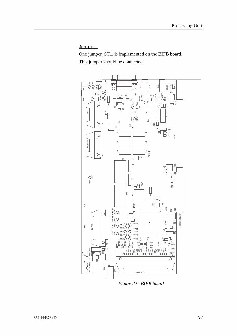
Processing Unit
77852-164378 / D
Jumpers
One jumper, ST1, is implemented on the BIFB board.This jumper should be connected.
Figure 22 BIFB board
C
29
R22 R24
R
38 R26
R
39
R
40
R
42
R
41
R
44
R
46
R
45
R
43
P12 TP37
TP35
TP36
R
16
U
6
R15
C30
C
27
U
5
C
23
C25
C18
C24
C
26
C
19
1
C
18
R
20
R
19
TP15 TP14
C16 A3
1C
1
C15
TP12
R
28
R
30
R
31
R
29
R
33
R
35
R
34
R
37
R
36
R
32
ST1
TESTPLUG
R
27
P16
P3
C32
C
31
D3
P16-
1 : V
CC
TP2
0
D1
IN
OU
T: BIF
1: B
IF2
SYSC
LKTA
XIO
SCIO
RIO
W T
P18
C
28
R23 R25 C
STR
B R21
TP30
TP26
TP28
TP24
TP29
TP3
3
TP3
4
VLTN T
P32
D
STR
B
TP27
TP25
TP23
TP1
9
C21
TP22
C22
C
20
TP1
6
TP21
TP1
7
BIF
B
P1
R17
TO B
SP
S.N
O.
U
4
C
17
R14
F4
P8
F3
C14
L7
P7
L6
R
7
C
11
TP
10
P15
R13 R12
ST2 C
13
R
11
C
12
C
5
L1
A1
C7
C
4
CO
AX 4
C6
SER
-
C
3
P11
R
9
R
10
R
8
P10
D4
SER
+
C10
L5
L3
L4
L2
C9
U
2
+24V
TP1
1
R
6 -2
4V
C
2
TP
7
TP
8
U
3
U
1
R5
R18
C
1
C
8
TP3
TP
6
DIRD2
CO
AX 2
TP
9
P9
R4 R3 R2
TP
4
TP
5 TX
R
1
RX
TP
1
A B
TP2
LED
TP13
+5V
CPU
ser
ial
TRIG
P2P1
3
TR
IGP1
4
IWR
(CD
5865
/211
725)
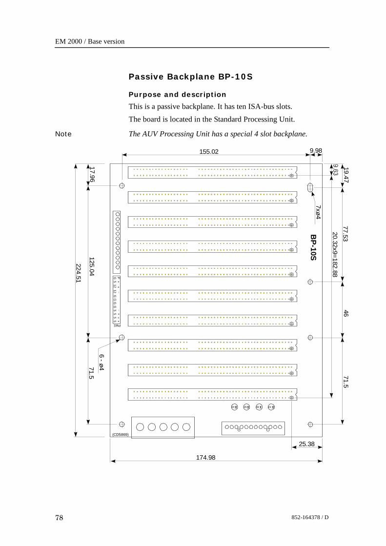
EM 2000 / Base version
78 852-164378 / D
Passive Backplane BP-10S
Purpose and description
This is a passive backplane. It has ten ISA-bus slots.The board is located in the Standard Processing Unit.
Note The AUV Processing Unit has a special 4 slot backplane.
9.98
PG
PW2
GG
GG
55
55
512
12+
++
++
174.98
17.96125.04
224.51
6 - ø471.5
19.47
155.02
7xø4
77.5320.32x9=182.88
BP-10S
4671.5
25.38(CD5869)
Processing Unit
79852-164378 / D
How it works
There are no active components on this backplane.
Facilities
LEDs
The LEDs are used as power supply indicators. There are fiveLEDs on the backplane:• + 5V• - 5V• + 12V• - 12V- 5V is not used and therefore not lit. The three other LEDsshould be lit at all times.
Test points
None
Links
None
Connections
+ 5V, + 12V and - 12Vdc.
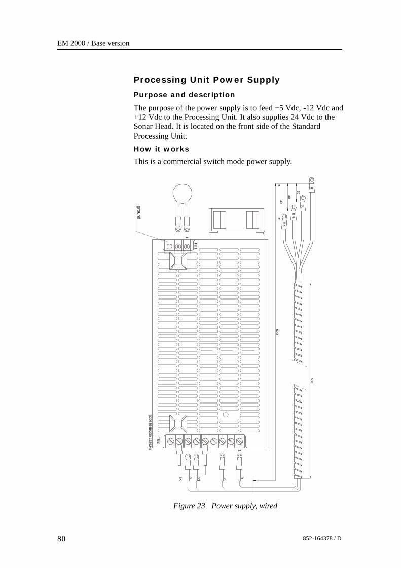
EM 2000 / Base version
80 852-164378 / D
Processing Unit Power Supply
Purpose and description
The purpose of the power supply is to feed +5 Vdc, -12 Vdc and+12 Vdc to the Processing Unit. It also supplies 24 Vdc to theSonar Head. It is located on the front side of the StandardProcessing Unit.How it works
This is a commercial switch mode power supply.
TB1
TB2
1
1
ground
R
BL
BN
BK
RBL
BN
BK
BK
550
620
20
30
40
(CD
5854B/290-133924)
Figure 23 Power supply, wired
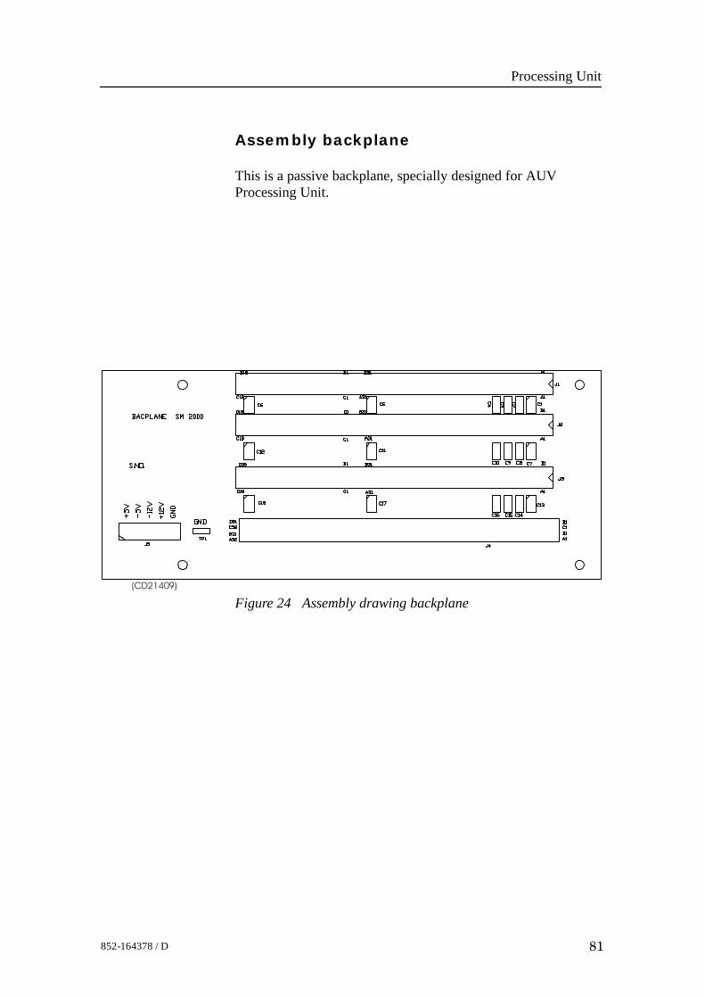
Processing Unit
81852-164378 / D
Assembly backplane
This is a passive backplane, specially designed for AUVProcessing Unit.
(CD21409)
Figure 24 Assembly drawing backplane
EM 2000 / Base version
82 852-164378 / D
6 SONAR HEAD
6.1 Description and main functions
OverviewThe EM 2000 Sonar Head consist of:• Transducer array• Transformer / preamplifier PCB’s which incorporates the
transducer matching band pass filter.s, and low noise gainamplifiers for 80 channels.
• Two PDH/MVX/ADC/Tx PCB’s. Each consist of 40channels and a transmitter driver.
• The HC2000 PCB, that includes a TMS32eC51processor, aserial line and a TAXI link interface.
• A power supply PCB, that includes DC/DC converters and acapacitor bank.
A single cable with an underwater plug, connects the SonarHead to the EM 2000 Processing Unit.
Topics
→ Sonar Head 150_ outline, page 83.→ Sonar Head 120_ outline, page 84→ Circuit boards description, page 85→ Theory of operation, page 85→ Theory of operation, page 86.→ Sonar Head, details, page 88.
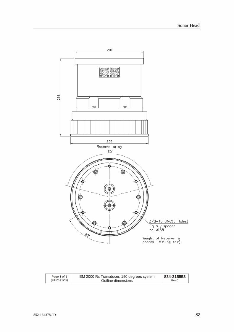
Sonar Head
83852-164378 / D
834-215553Rev.C
Page 1 of 1(CD21412C)
EM 2000 Rx Transducer, 150 degrees systemOutline dimensions
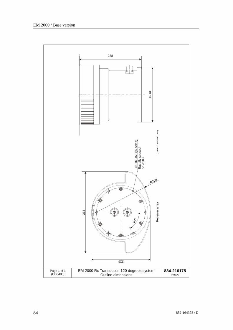
EM 2000 / Base version
84 852-164378 / D
314
~R209
Rec
eive
r arra
y
228
3/8-
16 U
NC
(6 h
oles
)E
qual
ly s
pace
don
ø18
8
60
238
ø210
(CD
6400
/ 83
4-21
6175
aa)
834-216175Rev.A
Page 1 of 1(CD6400)
EM 2000 Rx Transducer, 120 degrees systemOutline dimensions
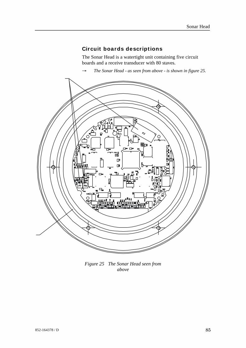
Sonar Head
85852-164378 / D
Circuit boards descriptionsThe Sonar Head is a watertight unit containing five circuitboards and a receive transducer with 80 staves.→ The Sonar Head - as seen from above - is shown in figure 25.
Figure 25 The Sonar Head seen fromabove
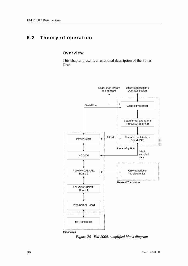
EM 2000 / Base version
86 852-164378 / D
6.2 Theory of operation
Overview
This chapter presents a functional description of the SonarHead.
Figure 26 EM 2000, simplified block diagram
Control Processor
Beamformer and SignalProcessor (BSPx2)
Serial lines to/fromthe sensors
Ethernet to/from theOperator Station
Processing Unit
(CD
5965
B)Beamformer Interface
Board (BIF)
Sonar Head
Transmit Transducer
Power Board
HC 2000
PDH/MVX/ADC/TxBoard 2
PDH/MVX/ADC/TxBoard 1
Preamplifier Board
Rx Transducer
Serial line
Only transducerNo electronics!
16-bitsampleddata
24 Vdc
Sonar Head
87852-164378 / D
Simplified block diagramThe simplified block diagram for the Sonar Head presents thefollowing main functions:• Reception• Processing→ Refer to figure 86.
Control functionsThe control functions in the Sonar Head are handled by theHC2000 board.
EM 2000 / Base version
88 852-164378 / D
6.3 Sonar Head details
Circuit boards and modules
PDH Receiver Board (PDH / MVX / ADC / Tx)
Each PDH board has a 40 channel receiver.→ The board is described on page 89.
HC 2000 Board
The HC 2000 receive commands from the host computer.→ The board is described on page 90.
Sonar Head
89852-164378 / D
PDH/MVX/ADC/Tx Board
Purpose and description
Each PDH board has 40 receiver channels and has the followingfunctions:• ten 4 channel TVG amplifier and demodulator hybrids
(DPH)• five 16 channel MVXs• five 12 bit A/D converters (real and imaginary samples)• bus interface circuits• one transmit driver (one half of Tx transducer)All digital control signals and the TVG control voltage aresupplied by the HC2000 board.
How it works
The signals from the preamlifier board are amplified in theVCA (Voltage Controlled Amplifier). This is located on thePDH hybrid. The signals are then filtered in a low-Q bandpassfilter, and fed through a second amplifer before being applied tothe quadrature demodulator.The quadrature demodulator consist of two parallel channels.Each channel has a mixer, a programmable amplifer (0-30 dB in6 dB steps), a switched capacitor lowpass filter andsimultaneous sample/hold amplifiers.

EM 2000 / Base version
90 852-164378 / D
HC 2000 Board
Purpose and description
The Head Control (HC 2000) Board receives commands fromthe host computer, on a half duplex RS-485 serial line. It sendssampled data out on a high speed serial line (TAXI link).Its purpose is to read data from 40 channels onPDH/MVX/ADC/Tx boards. The HC 2000 also controls thetransmitters.The HC 2000 board is connected to the PDH boards, powerboard and the Processing Unit through separate connectors.
Transmit Transducer
91852-164378 / D
7 TRANSMIT TRANSDUCER
7.1 Description and main functions
OverviewThe EM 2000 Transmit transducer contains no electronics. It iscontrolled by the Sonar Head. It needs to be submerged in waterand it is usually mounted close to the Sonar Head.A single cable with an underwater plug connects the Transmittransducer to the EM 2000 Sonar Head.
Topics
→ Transmit transducer outline, page 92.→ Modules, page 93
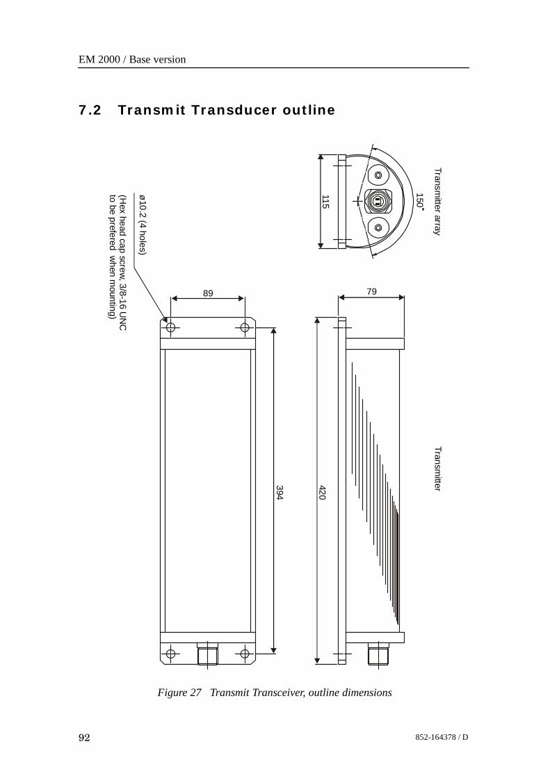
EM 2000 / Base version
92 852-164378 / D
7.2 Transmit Transducer outline
Figure 27 Transmit Transceiver, outline dimensions
89
394
79
420
Transmitter
Transmitter array
150
ø10.2 (4 holes)
(Hex head cap screw, 3/8-16 U
NC
to be prefered when m
ounting)
115

Transmit Transducer
93852-164378 / D
ModulesThe Transmit transducer is a watertight unit containing atransmit transducer with 2 elements.
EM 2000 / Base version
94 852-164378 / D
8 TROUBLESHOOTING
8.1 Messages (for UNIX only)
IntroductionThe EM 2000 provides numerous messages to inform you ofmajor and minor hardware and software errors.The messages, if they occur, will be displayed in the StatusDisplay in the Message field.The different utilities operating on the EM 2000 OperatorStation each issue several messages. These messages can besorted in four categories:• Display warnings• Display errors• Warnings• ErrorsThe messages presented as display warnings and warningsmerely point out small inaccuracies, and must be regarded asguidelines to the normal operation of the system.The display errors and operational errors reflect major andminor hardware and software errors, some of which must beacted upon to ensure the normal operational capability.The following chapters present all the possible messages, andbriefly explain the proper action to be taken.The information is provided as follows:<Nxxx>: -- <Message text>
Necessary action with applicable references.<Nxxx> is the message identifier. The number will allow you tofind the message easier in this document, and it tells you whichutility issued it.N - module/utility identifier.xxx - message identifierIn the list below you will find one letter representing eachmodule. Each module is described in its own chapter. Thenumber xxx is only an identifier.
S: setup messagesW: ESO/workstation messages
Troubleshooting
95852-164378 / D
L: launchpad messagesE: sound speed profile editor messagesP: Ping Display messages
The Hardware and CPU CMOS setup messages are presentedwith the exact same layout. The Hardware messages also startwith a message identifier <Nxxx>, and have a followingmessage text.The message text contains an error code which has to bedecoded to get the exact error condition.Most display errors are equipped with a help-textfunction,giving additional help on the errors. This text will, in mostcases, be identical to the action text found in this manual.
Topics
→ Setup messages, page 96.→ ESO messages, page 104.→ Launchpad messages, page 108.→ Sound Speed Profile Editor message, page 130.→ Ping Display messages, page 132.→ CMOS SETUP - standard Processing Unit, page 133.→ CMOS SETUP - AUV Processing Unit, page, page 139.
EM 2000 / Base version
96 852-164378 / D
Setup messagesThe following messages are presented by the Setup utility.Display WarningS10: -- Remember to set correct Gain parameters when using Manualbottom detection!Normal mode should be Range And Gain, which uses Automatic bottomdetection!
This mode should only be usedwhen automatic bottomdetection doesn’t work. Make sure that the Depth ToNormal Incidence depth indicator has a sensible value -it should have a value fairly close to the expected depth.
Display ErrorS15: -- Unable to write BIST output buffer to printfile <filename>.
An attemptwasmade to open the printfile in the systemdefaults directory for writing, but the operation failed.You should have full read and write access to thedirectory and all files in the directory.
Display ErrorS17: -- Unable to write BIST output buffer to file <filename>.
An attempt was made to open the savefile in the systemdefaults directory for writing, but the operation failed.You should have full read and write access to thedirectory and all files in the directory.
Display ErrorS18: -- No reply to the current BIST test!
Eachof theBuilt In SelfTest (BIST)commands is requiredto give a response within a fixed period of time. Thelength of this period varies with the type of test. TheProcessing Units has sub-units that may not respond intime, but this should be reported back to the operator aspart of the reply to the current BIST test.If the Processing Unit does not respond within theallocated time period, you should try one of the othertests to see if this is a general problem. If this is the case,or if the problem persists, you should try rebooting theProcessing Unit.
Display WarningS21: -- The profile is not deep enough, and should be extended. Whenyou select the OK button, the profile will be sent to the profile editor forautomatic extension.
All profiles used by the system require a maximumdepth of 12000 meters. Profiles less deep will beextended by the system, starting from the originalmaximum depth. The extension is based on standardtable values, with two points interpolated between lastvalue pair in profile and first table value pair.
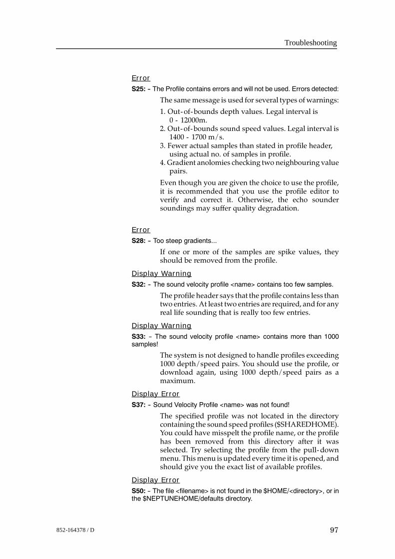
Troubleshooting
97852-164378 / D
ErrorS25: -- The Profile contains errors and will not be used. Errors detected:
The samemessage is used for several types ofwarnings:
1. Out-of-bounds depth values. Legal interval is0 - 12000m.
2. Out-of-bounds sound speed values. Legal interval is1400 - 1700 m/s.
3. Fewer actual samples than stated in profile header,using actual no. of samples in profile.
4. Gradient anolomies checking two neighbouring valuepairs.
Even though you are given the choice to use the profile,it is recommended that you use the profile editor toverify and correct it. Otherwise, the echo soundersoundings may suffer quality degradation.
ErrorS28: -- Too steep gradients...
If one or more of the samples are spike values, theyshould be removed from the profile.
Display WarningS32: -- The sound velocity profile <name> contains too few samples.
The profile header says that the profile contains less thantwo entries. At least two entries are required, and for anyreal life sounding that is really too few entries.
Display WarningS33: -- The sound velocity profile <name> contains more than 1000samples!
The system is not designed to handle profiles exceeding1000 depth/speed pairs. You should use the profile, ordownload again, using 1000 depth/speed pairs as amaximum.
Display ErrorS37: -- Sound Velocity Profile <name> was not found!
The specified profile was not located in the directorycontaining the soundspeedprofiles ($SHAREDHOME).You could have misspelt the profile name, or the profilehas been removed from this directory after it wasselected. Try selecting the profile from the pull-downmenu. Thismenu is updated every time it is opened, andshould give you the exact list of available profiles.
Display ErrorS50: -- The file <filename> is not found in the $HOME/<directory>, or inthe $NEPTUNEHOME/defaults directory.
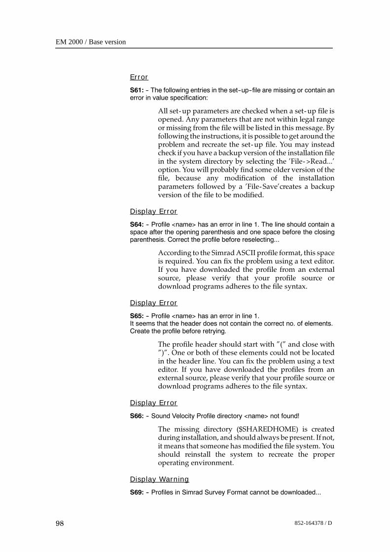
EM 2000 / Base version
98 852-164378 / D
Error
S61: -- The following entries in the set--up--file are missing or contain anerror in value specification:
All set-up parameters are checked when a set-up file isopened. Any parameters that are not within legal rangeormissing from the file will be listed in this message. Byfollowing the instructions, it is possible toget around theproblem and recreate the set-up file. You may insteadcheck if you have a backup version of the installation filein the system directory by selecting the ’File->Read...’option. You will probably find some older version of thefile, because any modification of the installationparameters followed by a ’File-Save’creates a backupversion of the file to be modified.
Display Error
S64: -- Profile <name> has an error in line 1. The line should contain aspace after the opening parenthesis and one space before the closingparenthesis. Correct the profile before reselecting...
According to the SimradASCII profile format, this spaceis required. You can fix the problem using a text editor.If you have downloaded the profile from an externalsource, please verify that your profile source ordownload programs adheres to the file syntax.
Display Error
S65: -- Profile <name> has an error in line 1.It seems that the header does not contain the correct no. of elements.Create the profile before retrying.
The profile header should start with ”(” and close with”)”. One or both of these elements could not be locatedin the header line. You can fix the problem using a texteditor. If you have downloaded the profiles from anexternal source, please verify that your profile source ordownload programs adheres to the file syntax.
Display Error
S66: -- Sound Velocity Profile directory <name> not found!
The missing directory ($SHAREDHOME) is createdduring installation, and shouldalways bepresent. If not,it means that someone has modified the file system. Youshould reinstall the system to recreate the properoperating environment.
Display Warning
S69: -- Profiles in Simrad Survey Format cannot be downloaded...
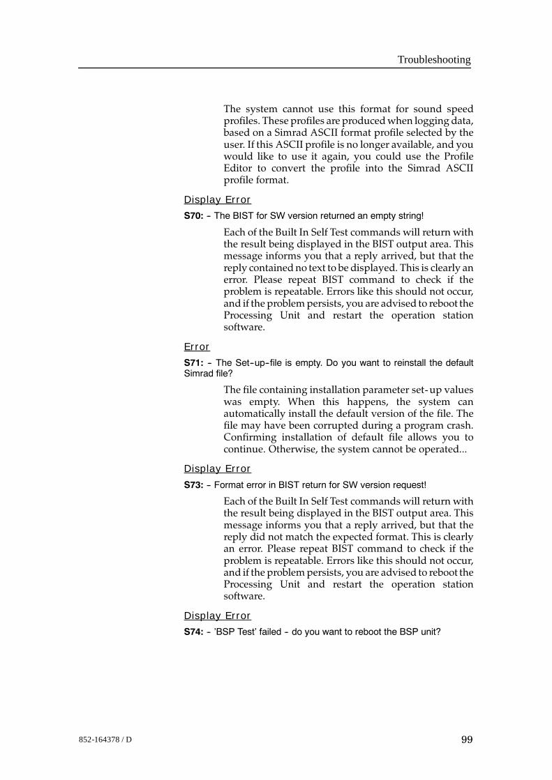
Troubleshooting
99852-164378 / D
The system cannot use this format for sound speedprofiles. These profiles are producedwhen logging data,based on a Simrad ASCII format profile selected by theuser. If this ASCII profile is no longer available, and youwould like to use it again, you could use the ProfileEditor to convert the profile into the Simrad ASCIIprofile format.
Display Error
S70: -- The BIST for SW version returned an empty string!
Each of the Built In Self Test commands will return withthe result being displayed in the BIST output area. Thismessage informs you that a reply arrived, but that thereply contained no text to be displayed. This is clearly anerror. Please repeat BIST command to check if theproblem is repeatable. Errors like this should not occur,and if the problempersists, you are advised to reboot theProcessing Unit and restart the operation stationsoftware.
Error
S71: -- The Set--up--file is empty. Do you want to reinstall the defaultSimrad file?
The file containing installation parameter set-up valueswas empty. When this happens, the system canautomatically install the default version of the file. Thefile may have been corrupted during a program crash.Confirming installation of default file allows you tocontinue. Otherwise, the system cannot be operated...
Display Error
S73: -- Format error in BIST return for SW version request!
Each of the Built In Self Test commands will return withthe result being displayed in the BIST output area. Thismessage informs you that a reply arrived, but that thereply did not match the expected format. This is clearlyan error. Please repeat BIST command to check if theproblem is repeatable. Errors like this should not occur,and if the problempersists, you are advised to reboot theProcessing Unit and restart the operation stationsoftware.
Display Error
S74: -- ’BSP Test’ failed -- do you want to reboot the BSP unit?
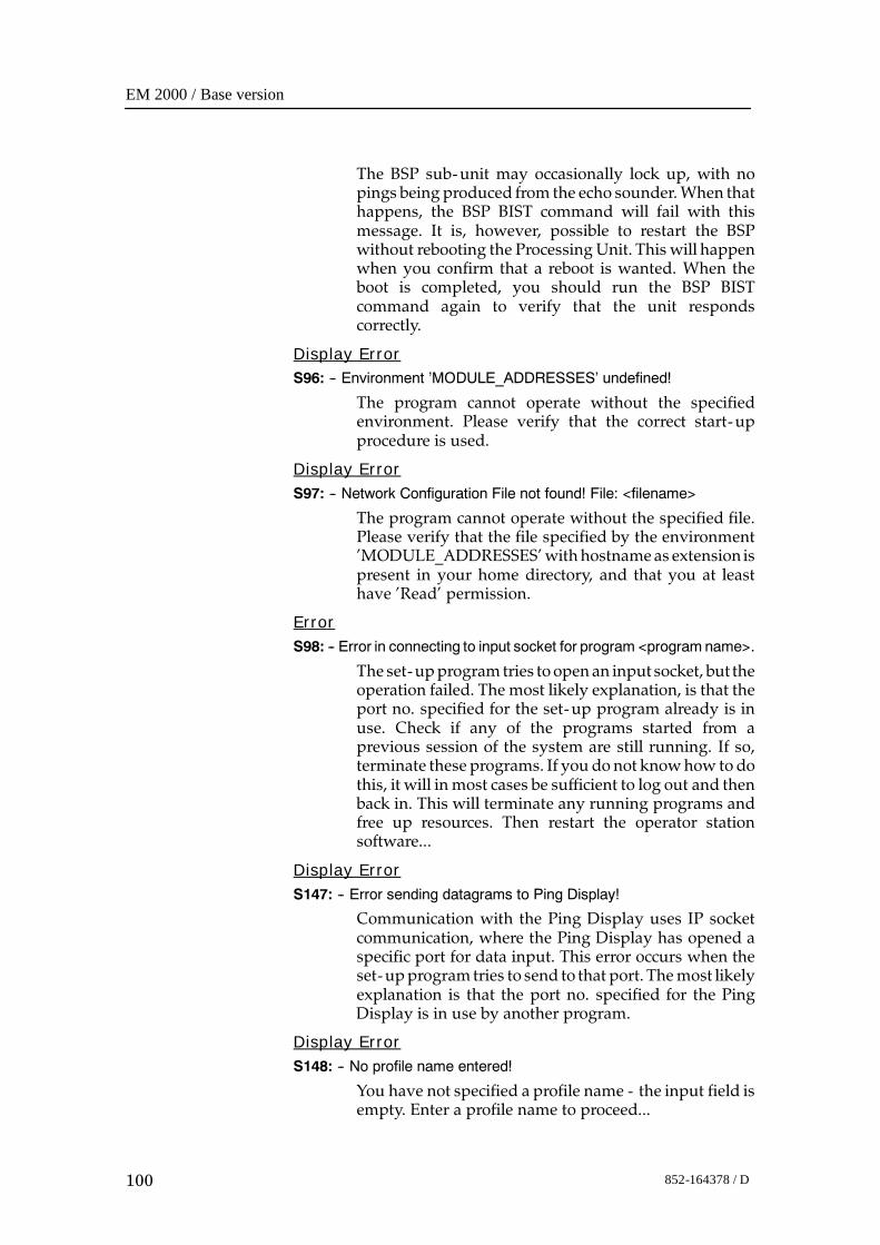
EM 2000 / Base version
100 852-164378 / D
The BSP sub-unit may occasionally lock up, with nopings being produced from the echo sounder.When thathappens, the BSP BIST command will fail with thismessage. It is, however, possible to restart the BSPwithout rebooting the Processing Unit. This will happenwhen you confirm that a reboot is wanted. When theboot is completed, you should run the BSP BISTcommand again to verify that the unit respondscorrectly.
Display ErrorS96: -- Environment ’MODULE_ADDRESSES’ undefined!
The program cannot operate without the specifiedenvironment. Please verify that the correct start-upprocedure is used.
Display ErrorS97: -- Network Configuration File not found! File: <filename>
The program cannot operate without the specified file.Please verify that the file specified by the environment’MODULE_ADDRESSES’withhostnameas extension ispresent in your home directory, and that you at leasthave ’Read’ permission.
ErrorS98: -- Error in connecting to input socket for program <program name>.
The set-upprogram tries toopen an inputsocket, but theoperation failed. The most likely explanation, is that theport no. specified for the set-up program already is inuse. Check if any of the programs started from aprevious session of the system are still running. If so,terminate these programs. If you donot knowhow todothis, it will in most cases be sufficient to log out and thenback in. This will terminate any running programs andfree up resources. Then restart the operator stationsoftware...
Display ErrorS147: -- Error sending datagrams to Ping Display!
Communication with the Ping Display uses IP socketcommunication, where the Ping Display has opened aspecific port for data input. This error occurs when theset-upprogram tries to send to that port. Themost likelyexplanation is that the port no. specified for the PingDisplay is in use by another program.
Display ErrorS148: -- No profile name entered!
You have not specified a profile name - the input field isempty. Enter a profile name to proceed...
Troubleshooting
101852-164378 / D
Display WarningS150: -- The file <filename> was empty, and factory defaults was read.Please verify all settings and save all settings using the ’File-->Save’menu option.
The specified file containing set-up parameters(runtime or installation)was empty.When this happens,the system automatically installs the default version ofthe file. The file may have been corrupted during aprogram crash.
Display ErrorS151: -- The file <filename> is not found in the $HOME directory, or inthe $NEPTUNEHOME/defaults directory. After verifying the settings,you may create the file by using the ’File-->Save’ menu option. Theprogram terminates when you select the OK button.
The specified file containing set-up parameters(runtime or installation) is missing from the systemdirectory, and was not located in any of the predefinedlocations for the file. The error indicates that the systemsomehow has been corrupted, possible due to manualoperations in the file system. It is advisable to reinstallthe system to re-establish system integrity.
Display ErrorS152: -- Not able to copy the file <filename> to $HOME/<filename>.The program terminates when you select the OK button.
The specified file containing set-up parameters(runtime or installation) was missing from the systemdirectory, and could not be copied to this directory. Duetoproblemswith thedirectory access. The error indicatesthat the system somehow has been corrupted, possibledue to manual operations in the file system. It isadvisable to reinstall the system to re-establish systemintegrity.
Display ErrorS206: -- Min. Depth must be less than Max. Depth!
It should be fairly easy to fix - just enter a minimumvalue less than the maximum value...
Display Error
S207: -- Max. Depth must be greater than Min. Depth!
It should be fairly easy to fix - just enter a maximumvalue greater than the minimum value...
Display ErrorS208: -- Legal interval: [<value>, <value>]
The input value is outside the specified interval -re-enter value to proceed...
EM 2000 / Base version
102 852-164378 / D
Display ErrorS211: -- Couldn’t locate Workspace of Main Program!
If this error occurs, it means that certain workspacefunctions will be disabled, but that the overallfunctionality will be present. It has been observed thatrestarting theOperator Station softwaremay remove theproblem.
Display ErrorS212: -- Couldn’t connect to SMS Server!
Occurs when the program is started independent of therest of the system, orwhen the operating environment isinsufficiently defined. It means that none of thefunctionality based on running an integrated systemwill be present, thereby rendering the systeminoperable. If restarting the system does not remove theproblem, it is likely, that the easiest way to fix it is toreinstall the software.
Display ErrorS213: -- Illegal Window Configuration Command received: <command>
An unknown workspace or window command wasreceived. Should not affect the main functionality of theprogram.
Display ErrorS214: -- Couldn’t send status to SMS Server!
This is a serious error, which should not occur. It reflectsinternal corruption in the communication link with therest of the system. Itmeans that none of the functionalitybased on running an integrated system will be present,thereby rendering the system inoperable. If restartingthe system does not remove the problem, it is likely, thatthe easiest way to fix it is to reinstall the software.
Display ErrorS215: -- Server Connection Broken!
This is a serious error, which should not occur. It reflectsinternal corruption in the communication link with therest of the system. Itmeans that none of the functionalitybased on running an integrated system will be present,thereby rendering the system inoperable. If restartingthe system does not remove the problem, it is likely, thatthe easiest way to fix it is to reinstall the software.
Display WarningS237: -- No profile downloaded...
The system has not received any download profiles.When downloading takes place, the set-up program isnotified of the profile name. So far, it seems that nothinghas arrived.
Troubleshooting
103852-164378 / D
Display Warning
S238: -- Profile not located in profile directory!
When downloading takes place, the set-up program isnotified of the profile name. The system has received adownload profile, but it could not be located in thedirectory used for sound speed profiles.
Display Error
S239: -- Sensor Offset + current sound speed exceeds maximum speedof 1700.0 m/s.
The system does not recognise sound speeds in waterexceeding 1700 m/s. To correct, enter an offset value,which keeps the sum of sound speed and offset valuebelow or equal to 1700 m/s.
EM 2000 / Base version
104 852-164378 / D
ESO messagesThe following messages are presented by the ESO utility.
Display error
W5: -- Serial Set--up--file <filename> missing. Install Default file?
The specified file is either removed or renamed.However, the default file provided will enable allfunctions on a system not extended with a serial portexpansion card.
Display error
W9: -- No Serial input device is open! Select the ’Smart Probe ProfileInputs’ as the current serial I/O function in the ’Workstation I/OInterfaces’ menu.
The serial port specified for this function could not beopened as expected probably due to error in read/writepermission, or that a non-existing device is specified inthe set-up- file.
Display error
W12: -- Unable to open temporary file <filename>!
The error occurs because of inaccurate read/writepermissions to the system directory. This is either aninstallation error, or an error introduced afterinstallation.
Display error
W17: -- Input Error. To enable new input, you must reselect the currentinput function.
The input format was not recognised. Reading from theserial portwas disabled to avoid further input, andmustbe reactivated by reselecting the input function.
Display warning
W22: -- No probe samples logged!
The sampling of probe values was terminated, but novalues were actually received. Check probe connectionsand serial port set-up.
Display warning
W26: -- The file <name> was empty. Factory Defaults was used instead.Please verify settings and use the ’File --> Save’ command to makesettings permanent.
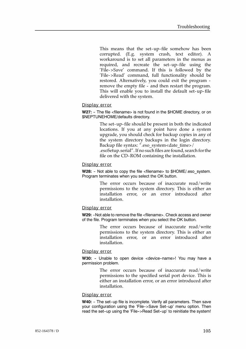
Troubleshooting
105852-164378 / D
This means that the set-up- file somehow has beencorrupted. (E.g. system crash, text editor). Aworkaround is to set all parameters in the menus asrequired, and recreate the set-up- file using the’File->Save’ command. If this is followed by the’File->Read’ command, full functionality should berestored. Alternatively, you could exit the program -remove the empty file - and then restart the program.This will enable you to install the default set-up- filedelivered with the system.
Display error
W27: -- The file <filename> is not found in the $HOME directory, or on$NEPTUNEHOME/defaults directory.
The set-up- file should be present in both the indicatedlocations. If you at any point have done a systemupgrade, you should check for backup copies in any ofthe system directory backups in the login directory.Backup file syntax: ”.eso_system<date_time>/.esoSetup.serial”. If no such files are found, search for thefile on the CD-ROM containing the installation.
Display errorW28: -- Not able to copy the file <filename> to $HOME/.eso_system.Program terminates when you select the OK button.
The error occurs because of inaccurate read/writepermissions to the system directory. This is either aninstallation error, or an error introduced afterinstallation.
Display error
W29: --Not able to remove the file <filename>. Check access and ownerof the file. Program terminates when you select the OK button.
The error occurs because of inaccurate read/writepermissions to the system directory. This is either aninstallation error, or an error introduced afterinstallation.
Display errorW30: -- Unable to open device <device--name>! You may have apermission problem.
The error occurs because of inaccurate read/writepermissions to the specified serial port device. This iseither an installation error, or an error introduced afterinstallation.
Display error
W40: -- The set--up file is incomplete. Verify all parameters. Then saveyour configuration using the ’File-->Save Set--up’ menu option. Thenread the set--up using the ’File-->Read Set--up’ to reinitiate the system!
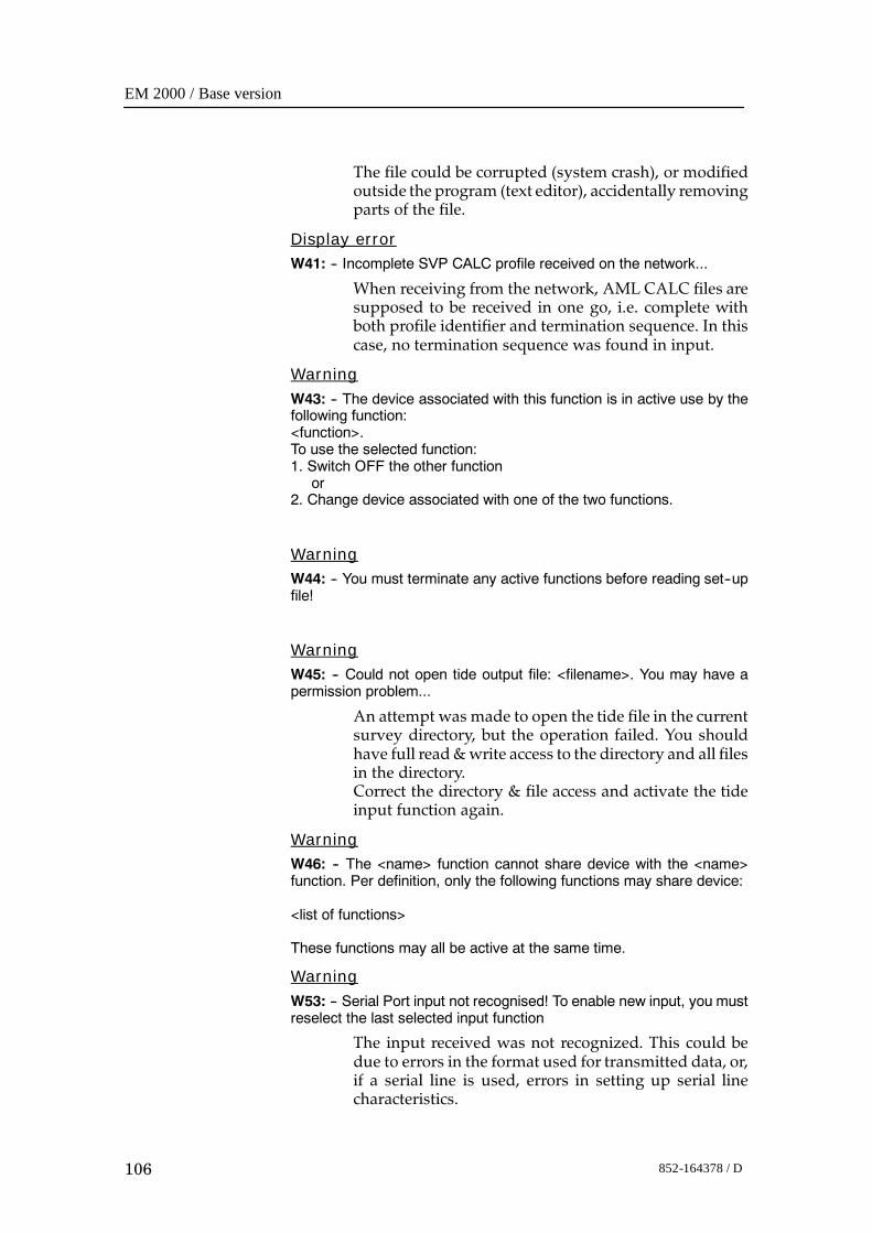
EM 2000 / Base version
106 852-164378 / D
The file could be corrupted (system crash), or modifiedoutside the program (text editor), accidentally removingparts of the file.
Display errorW41: -- Incomplete SVP CALC profile received on the network...
When receiving from the network, AML CALC files aresupposed to be received in one go, i.e. complete withboth profile identifier and termination sequence. In thiscase, no termination sequence was found in input.
WarningW43: -- The device associated with this function is in active use by thefollowing function:<function>.To use the selected function:1. Switch OFF the other function
or2. Change device associated with one of the two functions.
WarningW44: -- You must terminate any active functions before reading set--upfile!
WarningW45: -- Could not open tide output file: <filename>. You may have apermission problem...
An attempt was made to open the tide file in the currentsurvey directory, but the operation failed. You shouldhave full read&write access to the directory and all filesin the directory.Correct the directory & file access and activate the tideinput function again.
WarningW46: -- The <name> function cannot share device with the <name>function. Per definition, only the following functions may share device:
<list of functions>
These functions may all be active at the same time.
WarningW53: -- Serial Port input not recognised! To enable new input, you mustreselect the last selected input function
The input received was not recognized. This could bedue to errors in the format used for transmitted data, or,if a serial line is used, errors in setting up serial linecharacteristics.
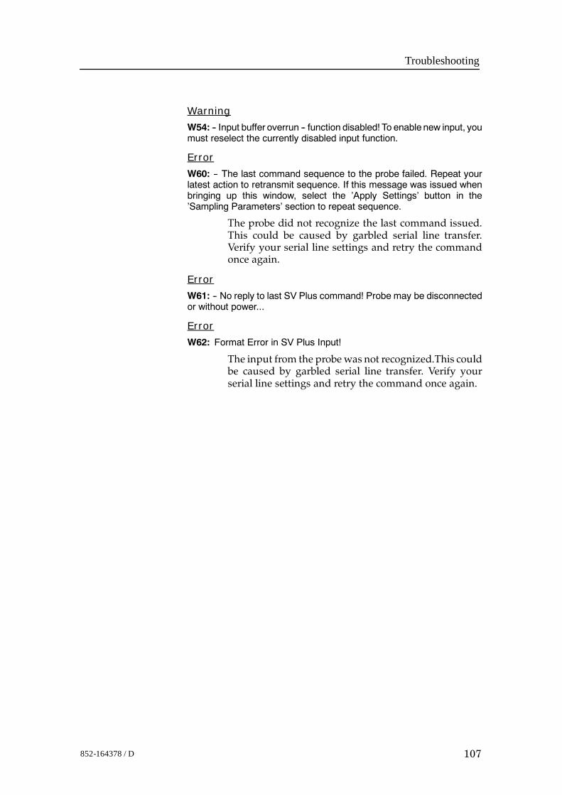
Troubleshooting
107852-164378 / D
Warning
W54: -- Input buffer overrun -- function disabled! To enable new input, youmust reselect the currently disabled input function.
Error
W60: -- The last command sequence to the probe failed. Repeat yourlatest action to retransmit sequence. If this message was issued whenbringing up this window, select the ’Apply Settings’ button in the’Sampling Parameters’ section to repeat sequence.
The probe did not recognize the last command issued.This could be caused by garbled serial line transfer.Verify your serial line settings and retry the commandonce again.
Error
W61: -- No reply to last SV Plus command! Probe may be disconnectedor without power...
Error
W62: Format Error in SV Plus Input!
The input from the probewas not recognized.This couldbe caused by garbled serial line transfer. Verify yourserial line settings and retry the command once again.
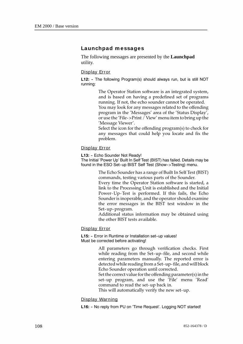
EM 2000 / Base version
108 852-164378 / D
Launchpad messages
The following messages are presented by the Launchpadutility.
Display Error
L12: -- The following Program(s) should always run, but is still NOTrunning:
The Operator Station software is an integrated system,and is based on having a predefined set of programsrunning. If not, the echo sounder cannot be operated.You may look for any messages related to the offendingprogram in the ’Messages’ area of the ’Status Display’,or use the ’File->Print /View’menu item tobring up the’Message Viewer’.Select the icon for the offending program(s) to check forany messages that could help you locate and fix theproblem.
Display Error
L13: -- Echo Sounder Not Ready!The Initial ’Power Up’ Built In Self Test (BIST) has failed. Details may befound in the ESO Set--up BIST Self Test (Show-->Testing) menu.
The Echo Sounder has a range of Built In Self Test (BIST)commands, testing various parts of the Sounder.Every time the Operator Station software is started, alink to the Processing Unit is established and the InitialPower-Up-Test is performed. If this fails, the EchoSounder is inoperable, and the operator should examinethe error messages in the BIST test window in theSet-up-program.Additional status information may be obtained usingthe other BIST tests available.
Display Error
L15: -- Error in Runtime or Installation set--up values!Must be corrected before activating!
All parameters go through verification checks. Firstwhile reading from the Set-up- file, and second whileentering parameters manually. The reported error isdetectedwhile reading froma Set-up- file, andwill blockEcho Sounder operation until corrected.Set the correct value for the offendingparameter(s) in theset-up program, and use the ’File’ menu ’Read’command to read the set-up back in.This will automatically verify the new set-up.
Display Warning
L16: -- No reply from PU on ’Time Request’. Logging NOT started!
Troubleshooting
109852-164378 / D
When activating logging of data, the system timestampssome of the datagrams used in the process.The time to usewas requested from the ProcessingUnit,but the reply did not arrivewithin a fixed period of time.This may be due to a Processing Unit running at fullcapacity, or - if the situation continues, while having anormal load on the system - that youmay have networkproblems.
Display Warning
L39: -- The <program name> program has not yet registered.Do you still want to wait for the program to come up?
When starting one of the programs used by the system,it will try to hook up to enable the necessarycommunication and supervision. If a program does notsucceed with this initial registration or hook up, it mayhave problems in the initial phase of starting up.Please refer to the ’Status Display, Messages Section’ forpossible error messages that may help sorting out theproblems.
Display Error
L40: -- The following Program(s) has not yet registered:
All programs started and supervised by the Launchpadestablishes a communication link with the systemwhenthey are launched. The listed program(s)did not succeedin establishing this link. It could be that the program (s)crashed before the linkup was attempted. If so, theprogram(s) has no possibility to communicate with therest of the system. You may try a manual start of thesystem in a window, to see if you can find any usefulmessages written in the window.
Warning
L45: -- Error reading input datagram...
Reading from the communication input socket failed.This is a low- level error, and should not occur if thesystemmanaged to start properly. If the error persist, tryterminating the system and restart the software again.
Display Error
L47: -- The Initial Power Up Self Test failed.Do you want to repeat the test?
Please refer to the testmenus in theEchoSounderSet-upprogram for details.
Warning
L52: -- Sound Speed At Transducer deviates more than X m/s from thecorresponding value defined by the current Sound Speed Profile!
EM 2000 / Base version
110 852-164378 / D
The sound speed at transducer depth received from theprobe exceeded the selected alarm offset 5 times in a row.You should verify that you are using the correct soundspeed profile, and also verify the size of the alarm offset.
Warning
L54: -- Current Center Depth exceeds original maximum depth from thecurrent Sound Speed Profile!
Center Beam Depth = <depth>Profile Max. Depth = <depth>.
The original profile had a maximum depth before theautomaticprofile extension extended theprofiledownto12000m. The depth you now are registering exceeds thisdepth. This could mean that your original profile isn’tdeep enough for this area.
Display Error
L59: -- Echo Sounder Not Ready!Error in Sound Speed Profile!
There are no samples in the current Sound SpeedProfile!Verify& correct current profile, or select anewone!Afterdoing this, you should run the Power Up Built In SelfTest (BIST) to enable the system.
Display Error
L60: -- Echo Sounder Not Ready!Error in echo sounder set--up parameters!
All parameters go through verification checks. Firstwhile reading from set-up- file and second whenentering parameters manually. The reported error isdetectedwhile reading from the set-up- file, andmust becorrected before continuing! After doing this, youshould run the Power Up Built In Self Test (BIST) toenable the system.
Display Error
L62: -- No Processing Unit has been detected while scanning theNetwork.Do you want to terminate the Launchpad?
The Operator Station is not receiving broadcastdatagrams from the Processing Unit. The continuingflow of broadcast datagrams tells the rest of the systemthat the PU is still alive. To prevent gaps in the line andpossible data corruption, logging was stopped. Possiblereasons for loss of contact:. Processing Unit is not Powered On. Network Cable Problems. Configuration Errors. Processing Unit Hardware / Software malfunction
Troubleshooting
111852-164378 / D
Error
L64: -- Connection timeout -- Logging switched Off!
The Operator Station stopped receiving broadcastdatagrams from the Processing Unit. The continuingflow of broadcasts datagrams tells the rest of the systemthat the PU is still alive. To prevent gaps in the line andpossible data corruption, logging was stopped. Possiblereasons for loss of contact:
.Processing Unit is not Powered On
.Network Cable Problems
.Configuration Errors
.Processing Unit Hardware / Software malfunction
Error
L65: -- Connection timeout -- Pinging switched Off!
The Operator Station stopped receiving broadcastdatagrams from the Processing Unit. The continuingflow of broadcast datagrams tells the rest of the systemthat the PU is still alive. The system status was set to NoPinging. Possible reasons for loss of contact:
.Processing Unit is not Powered On
.Network Cable Problems
.Configuration Errors
.Processing Unit Hardware / Software malfunction
Error
L66: -- Timeout in Processing Unit <--> Launchpad Connection!
TheOperator Station stopped receiving broadcasts fromthe Processing Unit. The continuing flow of broadcaststells the rest of the system that the PU is still alive.Possible reasons for loss of contact:
.Processing Unit is not Powered On
.Network Cable Problems
.Configuration Errors
.Processing Unit Hardware / Software malfunction
Display Error
L67: -- Format Error in Processing Unit Broadcast!
The Processing Units broadcast their presence on theNetwork. Such a broadcast message was received, butdid not meet the format specification.
Display Error
L76: -- No reply to the Initial Power--Up BIST.Do you want to Retry?
EM 2000 / Base version
112 852-164378 / D
The network connection is OK, but the Processing Unitis not responding. Cancel the current attempt. Power theProcessing Unit ’Off’ and then ’On’ again. Then tryrestarting the operating software.
Display ErrorL83: -- Could not create Config--file!
An attempt was made to store the current layoutconfiguration onto the system defaults directory, but theoperation failed. You should have full read & writeaccess to this directory.
Display ErrorL84: -- Error in retrieving ’All Workspaces’ info!
This is an internal error in the Launchpad, and shouldnever happen. If it does occur, it will be during saving ofthe layout configuration to file. You should then restartthe Operator Station software, and try the samecommand once again. This error may indicate internalproblems for the Launchpad program, and should bereported.
Display ErrorL85: -- Program <name> contains an error in the configuration--filestart--string!
This is a serious error. An attempt was made to updatethe main configuration file from data in memory. Theattempt failed because the internal information did notadhere to the syntax for this type of information. Youshould exit and restart the system to avoid loss ofoperational control.
Display ErrorL89: -- Could not create Log--file Backup!
An attempt was made to open the log- file in the systemdefaults directory, but the operation failed. You shouldhave full read & write access to this directory.
Display ErrorL99: -- Not able to change to Raw Data Directory <name> whengenerating Survey Parameters file.
An attempt was made to change the internal workingdirectory to the one used for raw data($RAWDATAHOME), but the operation failed. Pleaseverify that you have full read, write & execute access tothis directory.
Display WarningL111: -- Tape Operation Aborted!Reason:

Troubleshooting
113852-164378 / D
The reason for an aborted tape operationmay vary.Withthe exception of a user- triggered abort, the reason statedin the message body originates from the operatingsystem, but should be fairly easy to understand.Examples of this could be amessage stating that the tapedrive is offline or that no data cartridge is loaded.
Display WarningL112: -- You cannot delete the current survey!
The current survey could be active, meaning that theassociated directories and files are in use for data storageand processing. Removal of the current survey istherefore prohibited.
Display WarningL113: -- The Log--file is quite large: size X Mb -- reset recommended!
The messages in the log- file may be viewed using the’File->Print / View’ command. If the file contains toomany messages, it may be prove too ’crowded’ forpracticalpurposes. It is recommended that youpayheedto the suggestions of reset offered by the system. Use the’File->Reset Log- file’ option. If you are afraid of loosinguseful information, please note that any errors reportedwhile logging data, is logged in a separate log- file alongwith the survey data. Also remember, that you areoffered the option of backing up your log- file beforeresetting.
Display WarningL114: -- You cannot alter logging set--up while logging is Active!
Due to the programmed functionality of the system,some parameters (logging set-up & installationparameters) may not be modified, because that woulddisrupt proper functionality and data integrity.
Display WarningL117: -- The root partition of this system now has less than 2Mb spaceleft...
If the disk space on the root partition falls to zero, youmay experience various types of problems whileoperating the system. It is advisable to increase thisspace to a minimum of 10 - 20 Mb.
Display ErrorL120: -- Themain configuration file <filename> was not found. Since thisis a vital file for the system, the Launchpadwill terminatewhen you selectthe OK button...
This file contains the overall configuration of theoperator station software. The system can’t operatewithout this file. The file was copied to the systemdirectory during installation, and may have beenaccidentally removed.
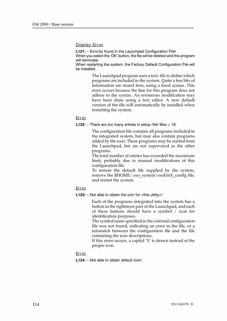
EM 2000 / Base version
114 852-164378 / D
Display Error
L121: -- Error(s) found in the Launchpad Configuration File!When you select the ’OK’ button, the file will be deleted and this programwill terminate.When restarting the system, the Factory Default Configuration File willbe installed.
The Launchpadprogram uses a text- file to definewhichprograms are included in the system. Quite a few bits ofinformation are stored here, using a fixed syntax. Thiserror occurs because the line for this program does notadhere to the syntax. An erroneous modification mayhave been done using a text editor. A new defaultversion of the file will automatically be installed whenrestarting the system.
Error
L122: -- There are too many entries in setup--file! Max = 18.
The configuration file contains all programs included inthe integrated system, but may also contain programsadded by the user. These programs may be started fromthe Launchpad, but are not supervised as the otherprograms.The total number of entries has exceeded the maximumlimit, probably due to manual modifications of thisconfiguration file.To restore the default file supplied by the system,remove the $HOME/.eso_system/esoEmX_config file,and restart the system.
Error
L123: -- Not able to obtain the icon for <this utility>!
Each of the programs integrated into the system has abutton in the rightmost part of the Launchpad, and eachof these buttons should have a symbol / icon foridentification purposes.The symbol name specified in the external configurationfile was not found, indicating an error in the file, or amismatch between the configuration file and the filecontaining the icon descriptions.If this error occurs, a capital ’X’ is drawn instead of theproper icon.
Error
L124: -- Not able to obtain default icon!
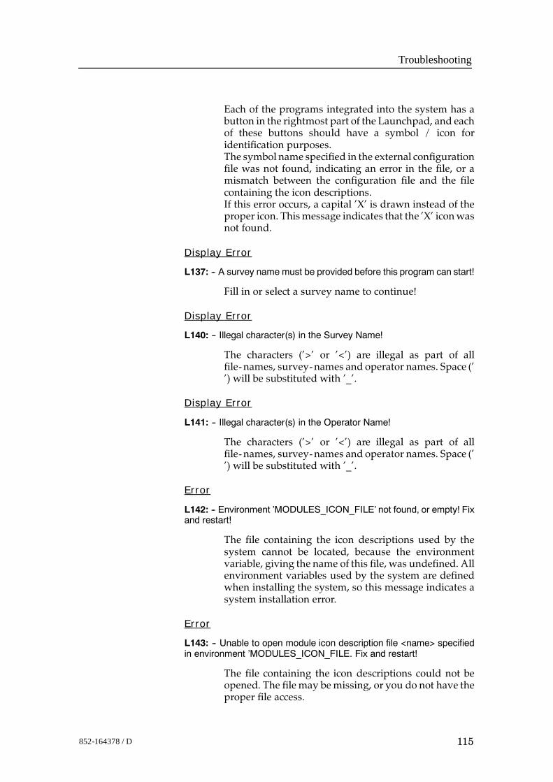
Troubleshooting
115852-164378 / D
Each of the programs integrated into the system has abutton in the rightmost part of the Launchpad, and eachof these buttons should have a symbol / icon foridentification purposes.The symbol name specified in the external configurationfile was not found, indicating an error in the file, or amismatch between the configuration file and the filecontaining the icon descriptions.If this error occurs, a capital ’X’ is drawn instead of theproper icon. Thismessage indicates that the ’X’ iconwasnot found.
Display Error
L137: -- A survey name must be provided before this program can start!
Fill in or select a survey name to continue!
Display Error
L140: -- Illegal character(s) in the Survey Name!
The characters (’>’ or ’<’) are illegal as part of allfile-names, survey-names and operator names. Space (’’) will be substituted with ’_’.
Display Error
L141: -- Illegal character(s) in the Operator Name!
The characters (’>’ or ’<’) are illegal as part of allfile-names, survey-names and operator names. Space (’’) will be substituted with ’_’.
Error
L142: -- Environment ’MODULES_ICON_FILE’ not found, or empty! Fixand restart!
The file containing the icon descriptions used by thesystem cannot be located, because the environmentvariable, giving the name of this file, was undefined. Allenvironment variables used by the system are definedwhen installing the system, so this message indicates asystem installation error.
Error
L143: -- Unable to open module icon description file <name> specifiedin environment ’MODULES_ICON_FILE. Fix and restart!
The file containing the icon descriptions could not beopened. The file may bemissing, or you do not have theproper file access.
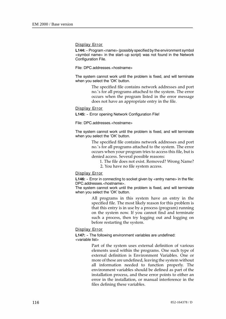
EM 2000 / Base version
116 852-164378 / D
Display ErrorL144: -- Program<name> (possibly specified by theenvironment symbol<symbol name> in the start--up script) was not found in the NetworkConfiguration File.
File: DPC.addresses.<hostname>
The system cannot work until the problem is fixed, and will terminatewhen you select the ’OK’ button.
The specified file contains network addresses and portno.’s for all programs attached to the system. The erroroccurs when the program listed in the error messagedoes not have an appropriate entry in the file.
Display ErrorL145: -- Error opening Network Configuration File!
File: DPC.addresses.<hostname>
The system cannot work until the problem is fixed, and will terminatewhen you select the ’OK’ button.
The specified file contains network addresses and portno.’s for all programs attached to the system. The erroroccurs when your program tries to access this file, but isdenied access. Several possible reasons:
1. The file does not exist. Removed? Wrong Name?2. You have no file system access.
Display ErrorL146: -- Error in connecting to socket given by <entry name> in the file:DPC.addresses.<hostname>.The system cannot work until the problem is fixed, and will terminatewhen you select the ’OK’ button.
All programs in this system have an entry in thespecified file. The most likely reason for this problem isthat this entry is in use by a process (program) runningon the system now. If you cannot find and terminatesuch a process, then try logging out and logging onbefore restarting the system.
Display ErrorL147: -- The following environment variables are undefined:<variable list>
Part of the system uses external definition of variouselements used within the programs. One such type ofexternal definition is Environment Variables. One ormore of these are undefined, leaving the systemwithoutall information needed to function properly. Theenvironment variables should be defined as part of theinstallation process, and these error points to either anerror in the installation, or manual interference in thefiles defining these variables.
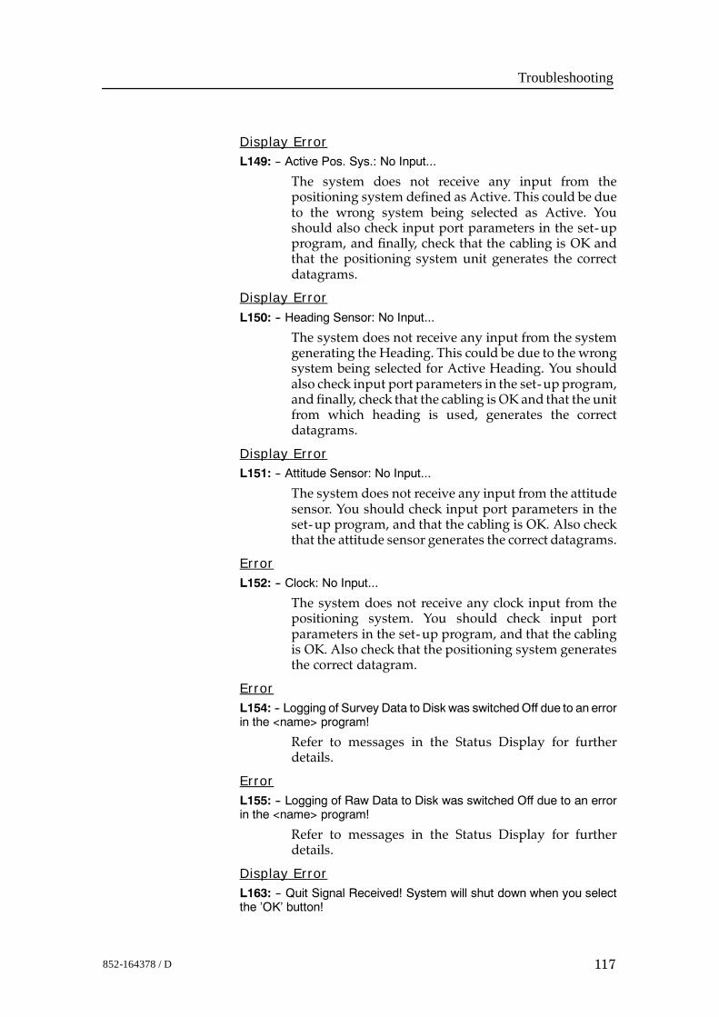
Troubleshooting
117852-164378 / D
Display ErrorL149: -- Active Pos. Sys.: No Input...
The system does not receive any input from thepositioning system defined as Active. This could be dueto the wrong system being selected as Active. Youshould also check input port parameters in the set-upprogram, and finally, check that the cabling is OK andthat the positioning system unit generates the correctdatagrams.
Display ErrorL150: -- Heading Sensor: No Input...
The system does not receive any input from the systemgenerating the Heading. This could be due to thewrongsystem being selected for Active Heading. You shouldalso check input port parameters in the set-up program,and finally, check that the cabling is OK and that the unitfrom which heading is used, generates the correctdatagrams.
Display ErrorL151: -- Attitude Sensor: No Input...
The system does not receive any input from the attitudesensor. You should check input port parameters in theset-up program, and that the cabling is OK. Also checkthat the attitude sensor generates the correct datagrams.
ErrorL152: -- Clock: No Input...
The system does not receive any clock input from thepositioning system. You should check input portparameters in the set-up program, and that the cablingis OK. Also check that the positioning system generatesthe correct datagram.
ErrorL154: -- Logging of Survey Data to Disk was switchedOff due to an errorin the <name> program!
Refer to messages in the Status Display for furtherdetails.
ErrorL155: -- Logging of Raw Data to Disk was switched Off due to an errorin the <name> program!
Refer to messages in the Status Display for furtherdetails.
Display ErrorL163: -- Quit Signal Received! System will shut down when you selectthe ’OK’ button!
EM 2000 / Base version
118 852-164378 / D
The system uses built- in mechanisms to handle signals(interrupts) originating both internally and externally.The typeof signal is described in themessage.All, exceptthe external Terminate Signal, is caused by errors in theprogram.
Display ErrorL164: -- Floating Point Exeption! System will shut down when you selectthe ’OK’ button!
The system uses built- in mechanisms to handle signals(interrupts) originating both internally and externally.The typeof signal is described in themessage.All, exceptthe external Terminate Signal, is caused by errors in theprogram.
Display ErrorL165: -- Bus Error! System will shut down when you select the ’OK’button!
The system uses built- in mechanisms to handle signals(interrupts) originating both internally and externally.The typeof signal is described in themessage.All, exceptthe external Terminate Signal, is caused by errors in theprogram.
Display ErrorL166: -- Segmentation Violation! System will shut down when you selectthe ’OK’ button!
The system uses built- in mechanisms to handle signals(interrupts) originating both internally and externally.The typeof signal is described in themessage.All, exceptthe external Terminate Signal, is caused by errors in theprogram.
Display ErrorL167: -- Terminate Signal Received! System will shut down when youselect the ’OK’ button!
The system uses built- in mechanisms to handle signals(interrupts) originating both internally and externally.The type of signal is described in themessage. All exceptthe external Terminate Signal, is caused by errors in theprogram.
Display ErrorL168: -- Illegal Instruction Signal Received! System will shut down whenyou select the ’OK’ button!
The system uses built- in mechanisms to handle signals(interrupts) originating both internally and externally.The typeof signal is described in themessage.All, exceptthe external Terminate Signal is caused by errors in theprogram.
Troubleshooting
119852-164378 / D
Display ErrorL169: -- SIGNAL <signal no.> received! Systemwill shut downwhen youselect the ’OK’ button!
The system uses built- in mechanisms to handle signals(interrupts) originating both internally and externally.The typeof signal is described in themessage.All, exceptthe external Terminate Signal, is caused by errors in theprogram.
ErrorL170: -- Unable to create Process List!
An attempt was made to open the process id log- file inthe systemdirectory forwriting, but theoperation failed.You should have full read&write access to the specifiedfile and directory.
ErrorL171: -- Unable to open Process List!
An attempt was made to open the process id log- file inthe system directory for reading, but the operationfailed. You should have full read & write access to thespecified file and directory.
Display ErrorL172: -- The following Programsare still running, andmust be terminatedbefore continuing:
The operating software uses several programs in anintegrated system. Each runningprogram is representedinternally as aprocess. It has beenobserved,mostly aftera crash, that these processes may continue to be activewhen they should not have been. The system detectsthese processes when it is restarted, and will, on usersconfirmation, issue termination commands before thesystem continues initialisation. But on rare occasions,the termination signal sent to these processes fails, andmanual intervention is requiredas instructed in the errormessage.
Display ErrorL173: -- The following Programs could not be terminated:
The operating software uses several programs in anintegrated system. Each runningprogram is representedinternally as aprocess. It has beenobserved,mostly aftera crash, that these processes continue to be active whenthey should not have been. The system detects theseprocesses when it is restarted, and will, on userconfirmation, issue termination commands before thesystem continues initialisation. But on rare occasions,the termination signal sent to these processes fails, andmanual intervention is requiredas instructed in the errormessage.
EM 2000 / Base version
120 852-164378 / D
Display Error
L176: -- The following Program(s) should always run, but is still NOTrunning:
All programs started and supervised by the Launchpadestablishes a communication link with the systemwhenthey are launched. The listed program(s)did not succeedin establishing this link. It could be that the program (s)crashed before the linkup was attempted. In that case,the program(s) has no possibility to communicate withthe rest of the system. You may try to start the systemmanually in a window, to see if you can find any usefulmessages written in thewindow. These programs are socalled system programs, and it will be impossible to runthe system when they are not running as intended.
Display Error
L177: -- Could not read Raw Data directory for survey <name>.
You do not have the correct access to the specifieddirectory. Correct ownership of directories and files aredefined when the system is installed, so this problemcould be the result of a manual operation in the filesystem. Pleaseverify that youhave read,write&executeaccess to the storage directories for raw data($RAWDATAHOME).
Display Error
L178: -- Not able to change to Survey Directory <name> when fetchingLine Statistics file!
The system could not perform an internal change ofdirectory to the specified directory due to error indirectory access. You should have read, write & executeaccess to all directories and files in the data storagelocations. Please verify and correct.
Display Error
L179: -- Not able to change to Home Directory when fetching LineStatistics file!
The system could not perform an internal change ofdirectory back to your login directory due to error indirectory access. You should have read, write & executeaccess to all directories and files in the data storagelocations. Please verify and correct.
Troubleshooting
121852-164378 / D
Display ErrorL181: -- Not able to copy the file <filename> to $HOME/<filename>.Program terminates when you select the OK button!
This is the file setting up the configuration of the statusfiled in the Launchpad. An attempt was made to copythis file from the system defaults directory, but failed.You should have read & write access to all files in thesystem directory and to the directory itself. Please verifyand correct.
Display ErrorL182: -- Could not open Operators File!
Open a terminal window, and go to the$HOME/.eso_system directory. Verify that you haveboth Read and Write access to the file’esoSetup.operators’.
Display ErrorL183: -- Not able to copy the Status Config file to <directory name>.Using default values...
This is the file setting up the configuration of the statusfields in the Launchpad. An attempt was made to copythe file from the system defaults directory, but failed.You should have read & write access to all files in thesystem directory and to the directory itself. Please verifyand correct.
Display ErrorL184: -- Status Config file not found.Using default values...
This is the file setting up the configuration of the statusfields in the Launchpad. It was not located in any of thepredefined locations. This is an error by itself - but thesystemuses adefault set-up, andwill be operable. If youdefine a new status set-up, remember to save the set-upfor later use.
Display ErrorL186: -- Could not init log--file!
It was not possible to create the file due to error inpermissions. You should have read & write access to allfiles in the system directory and to the directory itself.Please verify and correct.
Display ErrorL187: -- Could not open log--file for append!
It was not possible to open the file for append due toerror in file access. You should have read & write accessto all files in the system directory. Please verify andcorrect.
EM 2000 / Base version
122 852-164378 / D
Display Error
L189: -- Line Statistics File could not be opened!
Survey: <survey name>File: <line name>.linestat
The line statistics file for the specified line exists, but itcould not be opened due to error in file access. Youshould have read,write& execute access to all files in thedata storage directories. Please verify and correct.
Display Error
L190: -- Statistics File for Survey <survey name>, line <line name> isempty!
The line statistics file for the specified line exists, but itwas empty. It is difficult to state the reason for this,because all lines, no matter how small, should havesomething in this type of file. The file should beremoved.
Display Error
L193: -- Raw Data Parameters File for Survey <survey name> could notbe opened!
The line parameters file for the specified line exists, butit could not be opened due to error in file access. Youshould have read, write and execute access to all datastorage files and directories. Please verify and correct.
Display Error
L194: -- Survey Parameters File for Survey <survey name>, line <linename> is empty!
The line parameters file for the specified line exists, butit was empty. It is difficult to state the reason for this,because all lines, no matter how small, should havesomething in this type of file. The file should beremoved.
Display Error
L198: -- Not able to change to Survey Directory <directory name> whenfetching Line Statistics file!
There can be several reasons for this error, the mostprobable is that you don’t have the correct access to thespecified survey directory. Please verify that you haveread, write & execute access to all directories in the$PROCHOME location. ’$PROCHOME’ is anenvironment variable defining the top location of yourstorage area for processed data (not raw data).
Display Error
L209: -- You do not have WRITE access to file <name>.
Troubleshooting
123852-164378 / D
You do not have the correct access to the specified file.Correct ownership of directories and files are definedwhen the system is installed, so this problem could bethe result of amanual operation in the file system. Pleaseverify that you have read, write & execute access to theshared system directory ($SHAREDHOME) and all filesand subdirectories.
Display Error
L212: -- Operation cancelled!Echo Sounder not ready!
The system was interrupted while performing a PowerUp test. One of themain criteria for initiating the systemis that the Power Up test is completed without error.When this test is cancelled, the system is defined to beinoperable. It will remain so until the test is completedsuccessfully.
Display Error
L222: -- Line Statistics File not found.
Survey: <survey name>File: <line name>.linestat
The specified Line Statistics File does not exist. Whenterminating logging to a line, such a file is producedautomatically. This error indicates that the file systemhas been manually modified.
Display Error
L228: -- The file <filename> is not found on $HOME/<name> directory,or on $NEPTUNEHOME/defaults directory.Since this is a vital file for the system, the Launchpadwill terminate whenyou select the OK button...
The main configuration file is not located in any of thepredefined locations. The system cannot be operatedwithout this file. You should check if you have anybackups of the system directory - one is made duringevery upgrade / reinstall of the system. If that fails,reinstall the system.
Display Error
L229: -- The file <filename> is not found on $HOME/<name> directory,or on $NEPTUNEHOME/defaults directory.Using default set--up...
The main configuration file is not located in any of thepredefined locations. The system cannot be operatedwithout this file. You should check if you have anybackups of the system directory - one is made duringevery upgrade / reinstall of the system. If that fails,reinstall the system.
EM 2000 / Base version
124 852-164378 / D
Display WarningL230: -- Operator <name> has no Config--file...
Use the ’Update Operator’s ’Config- file’ popup menuoption on the ’All Programs’ icon in the ’Programs’sectionof theLaunchpad. Thiswill generate adefault filefor the current operator.
Display ErrorL231: -- The file <filename> is not found on $HOME/<name> directory,or on $NEPTUNEHOME/defaults directory.
The specified file is not located in any of the predefinedlocations. The system cannot be operated without thisfile. You should check if you have any backups of thesystem directory - there is made one during everyupgrade / reinstall of the system. If that fails, reinstallthe system.
Display ErrorL232: -- Not able to remove the file <file name>.
Check access andowner of the file. Program terminateswhen you selectthe OK button.
You do not have the correct access to the specified file.Correct ownership of directories and files are definedwhen the system is installed, so this problem could bethe result of amanual operation in the file system. Pleaseverify that you have read, write & execute access to thesystem directory and all files in this directory($HOME/.eso_system).
Display ErrorL233: -- Unable to open Table Of Contents!
You do not have the correct access to the selected file.Correct ownership of directories and files are definedwhen the system is installed, so this problem could bethe result of amanual operation in the file system. Pleaseverify that you have read, write & execute access to thesystem directory and all files in this directory($HOME/.eso_system).
Display ErrorL234: -- Unable to open temporary copy of the log--file!
It was not possible to open the file, due to an error in fileaccess. You should have read&write access to all files inthe system directory ($HOME/.eso_system). Pleaseverify and correct.
Display ErrorL235: -- Cannot allocate enough memory for viewing the log--file. Youshould reset the file using the ’File-->Reset Log--file’ option.
Troubleshooting
125852-164378 / D
The log- file was too big for the available memoryresources. If it is important to view the log- file, youcould try terminating as many of the programs aspossible before retrying. If the problem persists, youshould reset the log- file. When resetting, it is possible totake a backup copy of the log- file.
Display ErrorL297: -- Raw Data Parameters File forSurvey <survey name>Line <line name>could not be opened!
The parameter file for the specified survey exists, but itcould not be opened due to error in file access. Youshould have read, write and execute access to all datastorage files and directories. Please verify and correct.Due to the sequence of events producing this file, thiserror is not likely to occur.
Display ErrorL298: -- Survey Parameters File for Survey <name> does not exist!
The survey parameter file is based on the parameters foreach line, andpresents information regarding changes inline parameter set-up. For some reason, this file couldnot be produced. It may be, that there are no lines in thesurvey, or that the logged lines are corrupted.
Display ErrorL299: -- Raw Data Parameters File forSurvey <survey name>Line <line name>does not exist!
The file contains the parameter set-up being usedwhenlogging the line. For some reason, this file could not beproduced. It may be that the logged line is corrupted.
Display ErrorL300: -- Environment variable forNetwork ConfigurationFile not defined!
Some of the information required to have the systemrunning properly, is set outside of the actual programs,using environment variables. The specified variable isnot defined, andprobablymeans an installation error, ormanual modification in the definition of variables.
Display ErrorL301: -- Could not open Network Configuration File!File: <filename>
It was not possible to open the file due to error in fileaccess. You should have read&write access to all files inthe system directory. Please verify and correct.
EM 2000 / Base version
126 852-164378 / D
Display ErrorL302: -- Unable to open Serial Datagram Set--up--file
It was not possible to open the file due to error in fileaccess. You should have read&write access to all files inthe system directory. Please verify and correct.
Display ErrorL303: -- Unable to open Datagram Set--up--file!File: <filename>
This file contains the datagrams available forsubscription. It will not be possible to use thesubscription facility without this file. You should haveread & write access to all files in the system directory.Please verify and correct.
Display ErrorL304: -- Format error on input from Datagram Set--up--file!File: <filename>
Datagrams available for user-defined distribution aredefined using a fixed format. One or more of the entriesin this file does not fit this format. The safest way to fixthe problem is to remove the file, and restart the system.The filewill then be copied to the systemdirectory, usingthe default version supplied with the installation.
Display ErrorL318: -- Illegal format on IP address!
Format: ddd.ddd.ddd.ddd, where ’d’ is a digit.Leading zeros may be omitted.
The networking addresses used by the system mustfollow the specified syntax. Normally, if you havesubscribers running on the same computer as theoperating software, you should use the IP address of thiscomputer.
Display WarningL321: --This is the system’s broadcast IP address, and cannot bedeleted. If you were thinking of defining a new broadcast address, thisone will be automatically adjusted whenever the system’s IP address ismodified.
When removing an IP address, all programs having theselected address will be modified. Since the selectedaddress is of vital importance for the system, deletion ormodification is not allowed. The address is used toestablish and maintain the connection with the echosounder.
Display WarningL325: -- You cannot change the datagram set--up of the system’sreserved programs!
Troubleshooting
127852-164378 / D
Currently, only user-defined datagram subscriptionsmay be modified. Allowing the user to modify the flowof datagrams needed for proper operation of the systemcould result in operational problems.
Display Warning
L326: -- You cannot modify the IP address of the system’s reservedprograms!
Currently, only user-defined datagram subscriptionset-up may be modified. Allowing the user to modifythe networking set-up, needed for proper operation ofthe system, could result in operational problems.
Display Warning
L327: -- The specified IP Port no. is outside bounds!Legal interval: [2000, 6000]
The interval is limited to avoid interfering with theinternal port no. usage of the system. Using port no.’salready in use will give operational problems, both forthe system programs and for user programs.
Display Warning
L328: -- IPPort no. <port no.> is already in use by the <subscriber name>subscriber!Legal IP Port interval: [2000, 6000]
Opening and using the same port no. for reading is notallowed. You may send datagrams to the same port no.from several programs, but since you are definingdatagram distribution, you cannot use the same port asanother program.
Display Warning
L333: -- Logging cannot be started when Edit Mode is enabled in theSet--up menu!
The reason for this restriction is that when logging to aline is started, all current values of the installationparameters are loggedwith the data. And since only onesuch representation is possible per line, editing of theseparameters is prohibited when already logging.
Display Error
L334: -- PPS not received!
The system does not receive any input from the systemgenerating the 1PPS. This could be due to the wrongsystem being selected for 1PPS. You should also checkinput port parameters in the set-up program, andfinally, check that the cabling is OK and that the unitfrom which heading is used, generates the correctdatagrams.
EM 2000 / Base version
128 852-164378 / D
Display Warning
L335: -- Initial Power--Up Test was interrupted!Echo Sounder Not Ready!
The initial power-up test was interrupted by the user.And since it is an absolute requirement that this test issuccessfully completed, this test should be performed(with no errors reported).
Display Warning
L336: -- No Sound Speed Probe values received!
The system is supposed to receive Sound Speed Probevalues, bot does not receive any. Verify probeconnections, set-up and power.
Display Error
L337: -- Depth/Height Sensor: No Input...
The system is supposed to receive sensor input, butdoesnot receive any. Verify sensor connections, set-up andpower.
Warning
L355: -- Unknown NMEA Telegram received...
The datagram receivedwere not uniquely recognised. Itseems to be a NMEA datagram, but one not supportedby the system. The datagram may also contain formaterrors. Please refer to separate documentation ondatagram definitions.
Error
L356: -- Format Error in Remote Control Telegram!
The datagram received was recognised as a RemoteControl datagram, but the content does not adhere to thedatagram syntax. Please refer to separatedocumentation on datagram definitions.
Display Warning
L357: -- Datagram subscriber ’remoteLogging’ not defined!Use ’Options-->DatagramSubscriptions...’to enter ’remoteLogging’ as asubscriber. Remember to supply IP address and port.no. to receivedatagrams on!
The system has received a Remote Control datagram,but vital information is missing from the datagramdistribution set-up. Without this, none of the remotecontrol functionality will be available. The rest of thesounder will operate as normal.
Troubleshooting
129852-164378 / D
Display Warning
L358: -- No datagrams are selected for the ’remoteLogging’ subscriber!Use ’Options-->DatagramSubscriptions...’ and select datagrams forsubscription for the ’remoteLogging’ subscriber.
When using the Remote Control functionality, youmustdefine a selection of datagrams that you wantdistributed to the ’remoteLogging’ subscriber.Otherwise, nothing will flow to this subscriber, eventhough it is properlydefinedwith an IP address andportnumber.
Display Error
L364: -- The system is currently configured NOT to launch the SurveyDisplay automatically. Changing this mode requires changing theconfiguration file...
Some installations have their own Survey Controlsoftware. The message indicates that the currentconfiguration of the system has disabled this particularfeature. Please refer to the documentation forinformation on how to enable this software.
Display Warning
L372: -- Could not verify incoming profile!
The Profile Editor is already running, and profileverification is currently suspended. Terminating thecurrent editor session will automatically bring up thereceived profile for verification.
Display Error
L400: -- Could not open print tmp--file.
You do not have the correct access to awork- file in yourown home directory. Correct ownership of directoriesand files are definedwhen the system is installed, so thisproblem could be the result of a manual operation in thefile system. Please verify that you have read, write &execute access to your login directory and the files in thisdirectory.
Display Error
L401: -- Error in Launchpad Message Server Initialize!
Some system resources could not be allocated, becausesome other program is holding these resources. Check ifany of the programs started from a previous session ofthe system are still running. If so, terminate theseprograms. If you do not know how to do this, it will inmost cases be sufficient to log out and then back in. Thiswill terminate any running programs and free upresources. Then restart the operator station software...
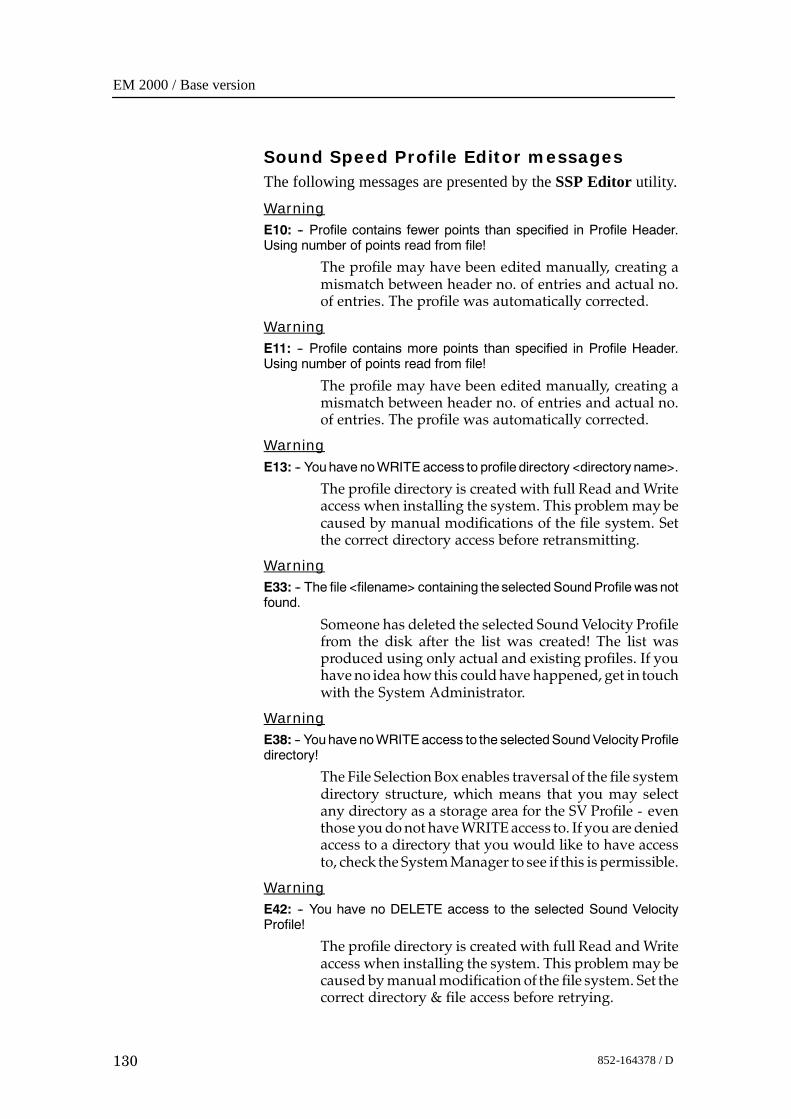
EM 2000 / Base version
130 852-164378 / D
Sound Speed Profile Editor messagesThe following messages are presented by the SSP Editor utility.
WarningE10: -- Profile contains fewer points than specified in Profile Header.Using number of points read from file!
The profile may have been edited manually, creating amismatch between header no. of entries and actual no.of entries. The profile was automatically corrected.
WarningE11: -- Profile contains more points than specified in Profile Header.Using number of points read from file!
The profile may have been edited manually, creating amismatch between header no. of entries and actual no.of entries. The profile was automatically corrected.
WarningE13: -- Youhave noWRITE access to profile directory <directory name>.
The profile directory is created with full Read andWriteaccess when installing the system. This problemmay becaused by manual modifications of the file system. Setthe correct directory access before retransmitting.
WarningE33: -- The file <filename> containing the selected SoundProfile was notfound.
Someone has deleted the selected SoundVelocity Profilefrom the disk after the list was created! The list wasproduced using only actual and existing profiles. If youhaveno idea howthis couldhave happened, get in touchwith the System Administrator.
WarningE38: -- YouhavenoWRITEaccess to the selectedSoundVelocity Profiledirectory!
The File Selection Box enables traversal of the file systemdirectory structure, which means that you may selectany directory as a storage area for the SV Profile - eventhoseyoudonothaveWRITEaccess to. If you aredeniedaccess to a directory that you would like to have accessto, check theSystemManager to see if this is permissible.
WarningE42: -- You have no DELETE access to the selected Sound VelocityProfile!
The profile directory is created with full Read andWriteaccess when installing the system. This problemmay becaused bymanualmodification of the file system. Set thecorrect directory & file access before retrying.
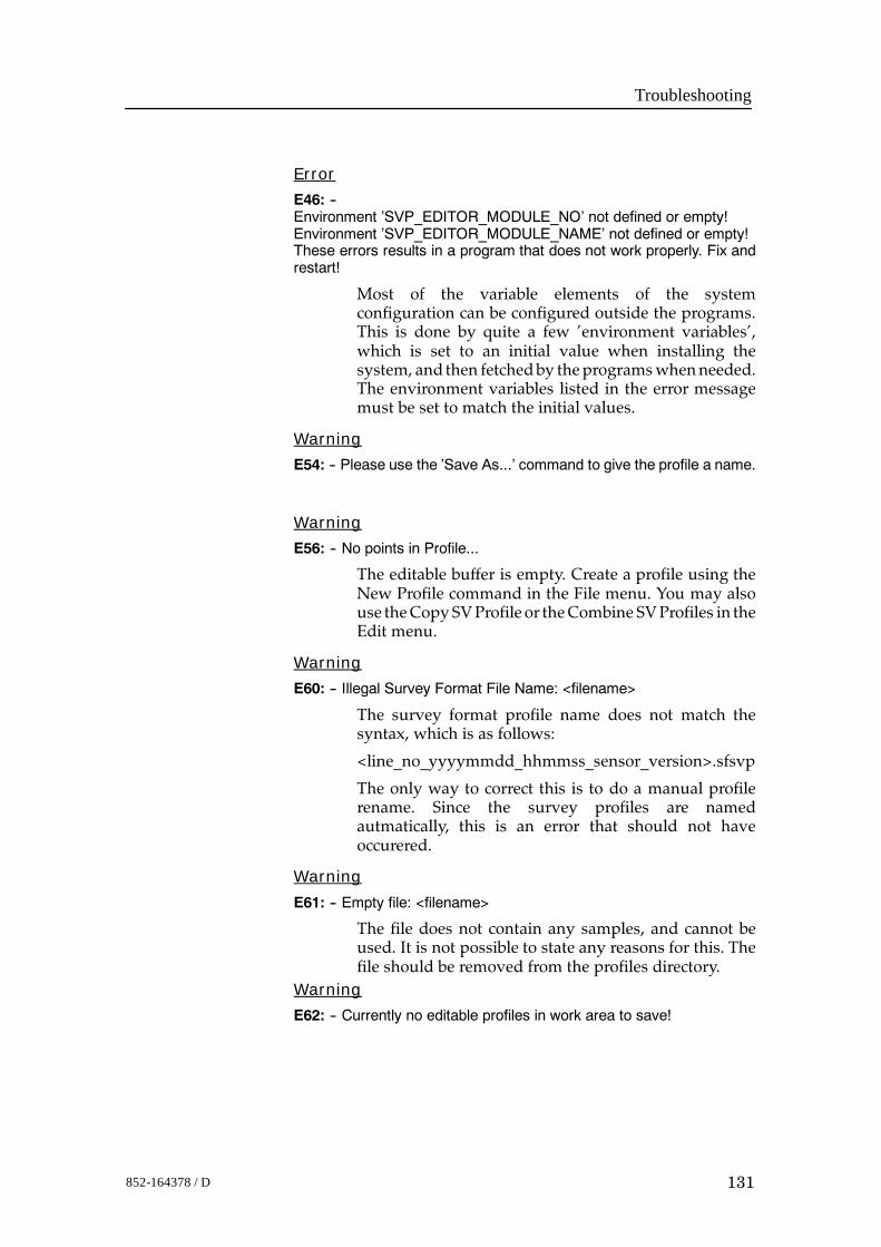
Troubleshooting
131852-164378 / D
Error
E46: --Environment ’SVP_EDITOR_MODULE_NO’ not defined or empty!Environment ’SVP_EDITOR_MODULE_NAME’ not defined or empty!These errors results in a program that does not work properly. Fix andrestart!
Most of the variable elements of the systemconfiguration can be configured outside the programs.This is done by quite a few ’environment variables’,which is set to an initial value when installing thesystem, and then fetchedby theprogramswhenneeded.The environment variables listed in the error messagemust be set to match the initial values.
Warning
E54: -- Please use the ’Save As...’ command to give the profile a name.
Warning
E56: -- No points in Profile...
The editable buffer is empty. Create a profile using theNew Profile command in the File menu. You may alsouse theCopySVProfile or theCombine SVProfiles in theEdit menu.
Warning
E60: -- Illegal Survey Format File Name: <filename>
The survey format profile name does not match thesyntax, which is as follows:
<line_no_yyyymmdd_hhmmss_sensor_version>.sfsvp
The only way to correct this is to do a manual profilerename. Since the survey profiles are namedautmatically, this is an error that should not haveoccurered.
Warning
E61: -- Empty file: <filename>
The file does not contain any samples, and cannot beused. It is not possible to state any reasons for this. Thefile should be removed from the profiles directory.
Warning
E62: -- Currently no editable profiles in work area to save!
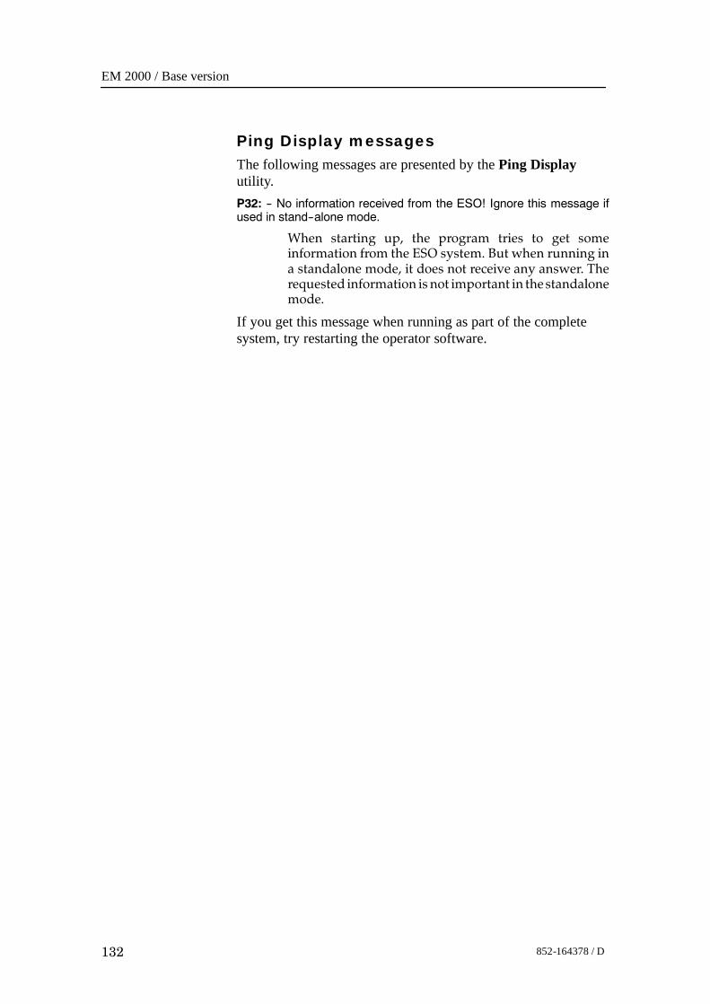
EM 2000 / Base version
132 852-164378 / D
Ping Display messagesThe following messages are presented by the Ping Displayutility.P32: -- No information received from the ESO! Ignore this message ifused in stand--alone mode.
When starting up, the program tries to get someinformation from the ESO system. But when running ina standalone mode, it does not receive any answer. Therequested information is not important in thestandalonemode.
If you get this message when running as part of the completesystem, try restarting the operator software.
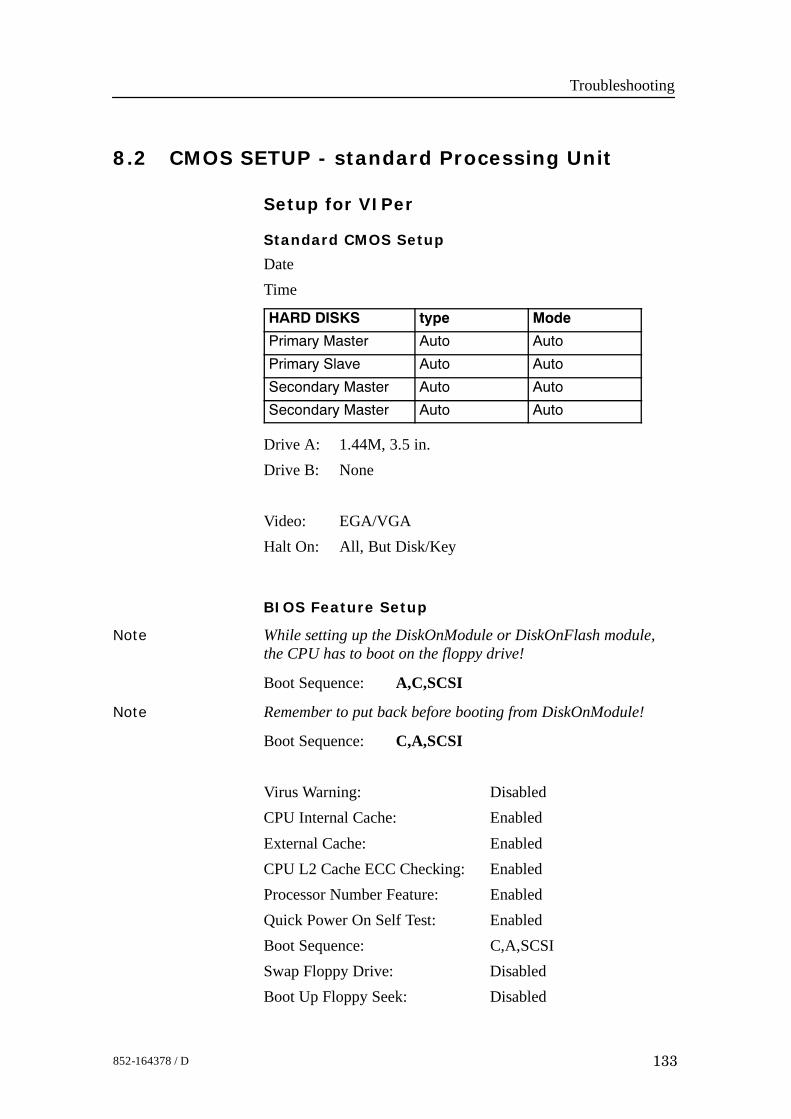
Troubleshooting
133852-164378 / D
8.2 CMOS SETUP - standard Processing Unit
Setup for VIPer
Standard CMOS Setup
DateTime
HARD DISKS type Mode
Primary Master Auto Auto
Primary Slave Auto Auto
Secondary Master Auto Auto
Secondary Master Auto Auto
Drive A: 1.44M, 3.5 in.Drive B: None
Video: EGA/VGAHalt On: All, But Disk/Key
BIOS Feature Setup
Note While setting up the DiskOnModule or DiskOnFlash module,the CPU has to boot on the floppy drive!
Boot Sequence: A,C,SCSI
Note Remember to put back before booting from DiskOnModule!
Boot Sequence: C,A,SCSI
Virus Warning: DisabledCPU Internal Cache: EnabledExternal Cache: EnabledCPU L2 Cache ECC Checking: EnabledProcessor Number Feature: EnabledQuick Power On Self Test: EnabledBoot Sequence: C,A,SCSISwap Floppy Drive: DisabledBoot Up Floppy Seek: Disabled
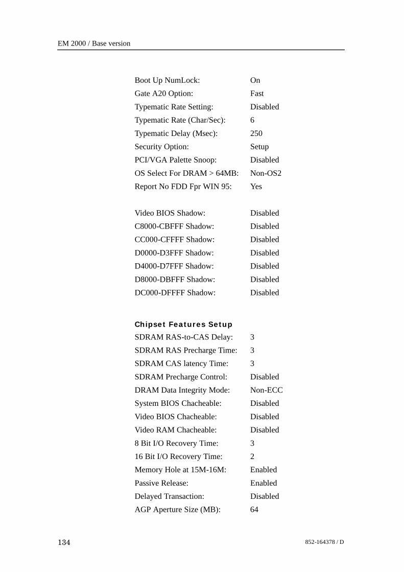
EM 2000 / Base version
134 852-164378 / D
Boot Up NumLock: OnGate A20 Option: FastTypematic Rate Setting: DisabledTypematic Rate (Char/Sec): 6Typematic Delay (Msec): 250Security Option: SetupPCI/VGA Palette Snoop: DisabledOS Select For DRAM > 64MB: Non-OS2Report No FDD Fpr WIN 95: Yes
Video BIOS Shadow: DisabledC8000-CBFFF Shadow: DisabledCC000-CFFFF Shadow: DisabledD0000-D3FFF Shadow: DisabledD4000-D7FFF Shadow: DisabledD8000-DBFFF Shadow: DisabledDC000-DFFFF Shadow: Disabled
Chipset Features Setup
SDRAM RAS-to-CAS Delay: 3SDRAM RAS Precharge Time: 3SDRAM CAS latency Time: 3
SDRAM Precharge Control: DisabledDRAM Data Integrity Mode: Non-ECCSystem BIOS Chacheable: DisabledVideo BIOS Chacheable: DisabledVideo RAM Chacheable: Disabled8 Bit I/O Recovery Time: 316 Bit I/O Recovery Time: 2Memory Hole at 15M-16M: Enabled
Passive Release: EnabledDelayed Transaction: DisabledAGP Aperture Size (MB): 64
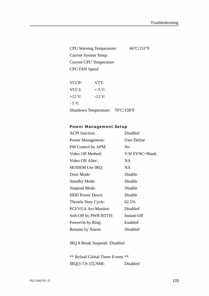
Troubleshooting
135852-164378 / D
CPU Warning Temperature: 66°C/151°FCurrent System Temp:Current CPU TemperatureCPU FAN Speed
VCCP: VTT:VCC3: + 5 V:+12 V: -12 V:- 5 V:Shutdown Temperature: 70°C/158°F
Power Management Setup
ACPI function: DisabledPower Management: User DefinePM Control by APM: NoVideo Off Method: V/H SYNC+BlankVideo Off After: NAMODEM Use IRQ: NADoze Mode: DisableStandby Mode: DisableSuspend Mode: Disable
HDD Power Down: DisableThrottle Duty Cycle: 62.5%PCI/VGA Act-Monitor: DisabledSoft-Off by PWR-BTTN: Instant-OffPowerOn by Ring: EnabledResume by Alarm: Disabled
IRQ 8 Break Suspend: Disabled
** Reload Global Timer Events **IRQ[3-7,9-15],NMI: Disabled
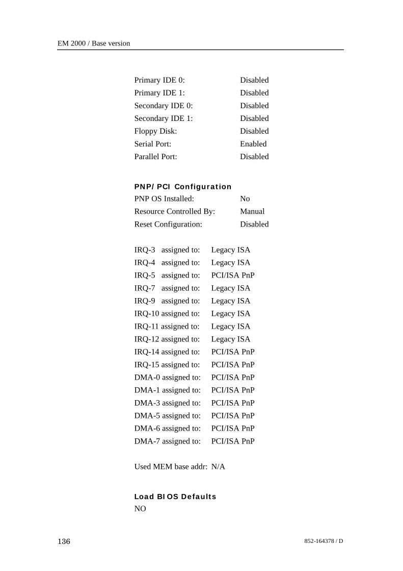
EM 2000 / Base version
136 852-164378 / D
Primary IDE 0: DisabledPrimary IDE 1: DisabledSecondary IDE 0: DisabledSecondary IDE 1: DisabledFloppy Disk: DisabledSerial Port: EnabledParallel Port: Disabled
PNP/PCI Configuration
PNP OS Installed: NoResource Controlled By: ManualReset Configuration: Disabled
IRQ-3 assigned to: Legacy ISAIRQ-4 assigned to: Legacy ISAIRQ-5 assigned to: PCI/ISA PnPIRQ-7 assigned to: Legacy ISAIRQ-9 assigned to: Legacy ISAIRQ-10 assigned to: Legacy ISAIRQ-11 assigned to: Legacy ISAIRQ-12 assigned to: Legacy ISAIRQ-14 assigned to: PCI/ISA PnPIRQ-15 assigned to: PCI/ISA PnPDMA-0 assigned to: PCI/ISA PnPDMA-1 assigned to: PCI/ISA PnPDMA-3 assigned to: PCI/ISA PnPDMA-5 assigned to: PCI/ISA PnPDMA-6 assigned to: PCI/ISA PnPDMA-7 assigned to: PCI/ISA PnP
Used MEM base addr: N/A
Load BIOS Defaults
NO

Troubleshooting
137852-164378 / D
Load Setup Defaults
NO
Integrated peripherals
IDE HDD Block Mode: EnabledIDE Primary Master PIO: AutoIDE Primary Slave PIO: AutoIDE Secondary Master PIO: AutoIDE Secondary Slave PIO: AutoIDE Primary Master UDMA: AutoIDE Primary Slave UDMA: AutoIDE Secondary Master UDMA: AutoIDE Secondary Slave UDMA: AutoOn-Chip Primary PCI IDE: EnabledOn-Chip Secondary PCI IDE: EnabledUSB Keyboard Support: DisabledInit Display first: PCI Slot
KBC input clock: 8 MHzOnboard FDC Controller: EnabledOnboard Serial Port 1: 3F8/IRQ4Onboard Serial Port 2: 2F8/IRQ3UART Mode Select: Normal
Onboard Parallel Port: 378/IRQ7Parallel Port Mode: SPP
Supervisor password
PASSWORD DISABLED
User password
PASSWORD DISABLED
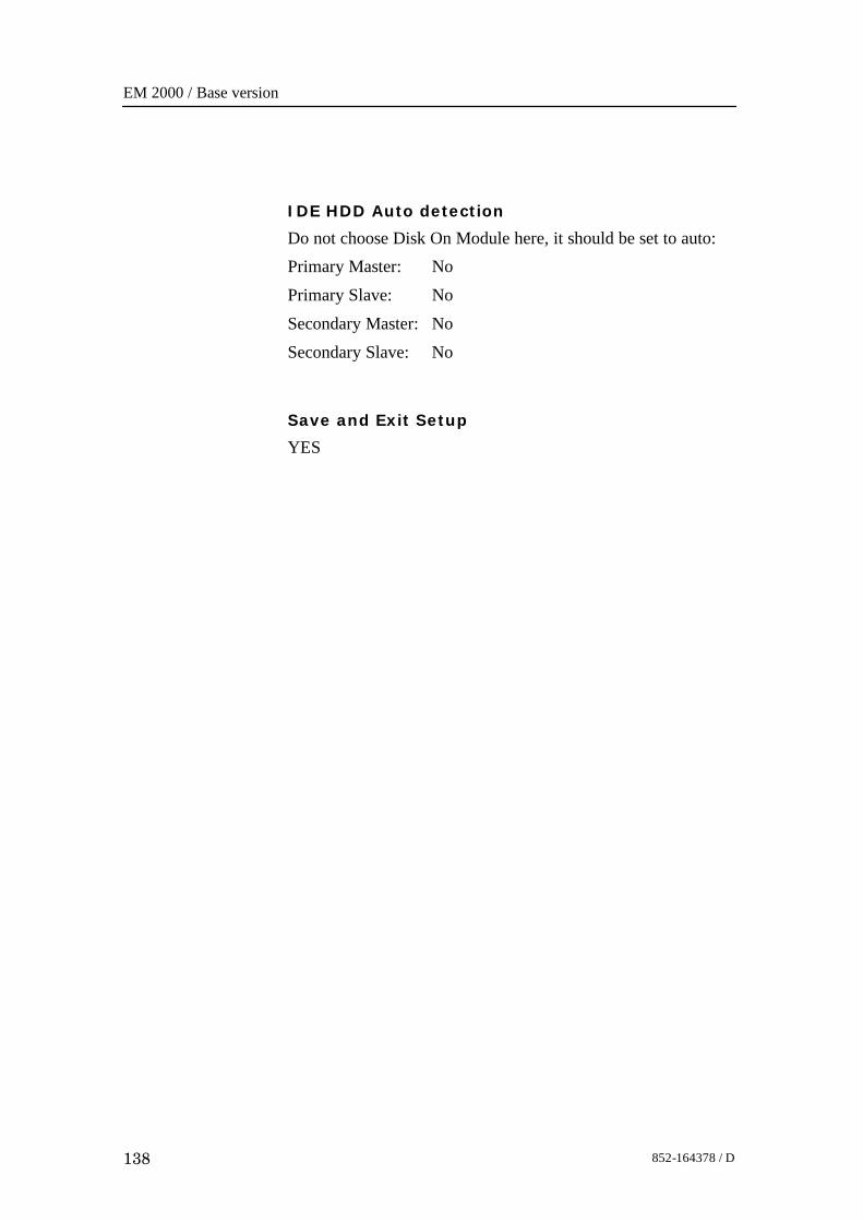
EM 2000 / Base version
138 852-164378 / D
IDE HDD Auto detection
Do not choose Disk On Module here, it should be set to auto:Primary Master: NoPrimary Slave: NoSecondary Master: NoSecondary Slave: No
Save and Exit Setup
YES
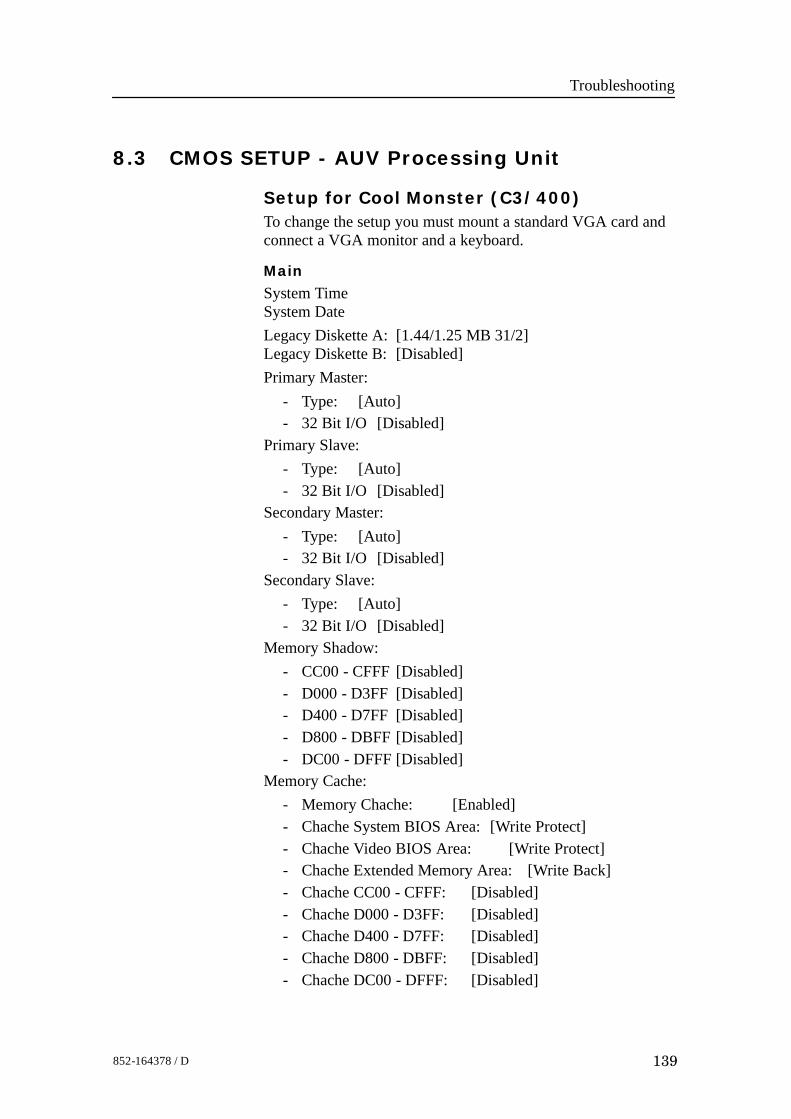
Troubleshooting
139852-164378 / D
8.3 CMOS SETUP - AUV Processing Unit
Setup for Cool Monster (C3/400)To change the setup you must mount a standard VGA card andconnect a VGA monitor and a keyboard.
Main
System TimeSystem DateLegacy Diskette A: [1.44/1.25 MB 31/2]Legacy Diskette B: [Disabled]Primary Master:
- Type: [Auto]- 32 Bit I/O [Disabled]
Primary Slave:- Type: [Auto]- 32 Bit I/O [Disabled]
Secondary Master:- Type: [Auto]- 32 Bit I/O [Disabled]
Secondary Slave:- Type: [Auto]- 32 Bit I/O [Disabled]
Memory Shadow:- CC00 - CFFF [Disabled]- D000 - D3FF [Disabled]- D400 - D7FF [Disabled]- D800 - DBFF [Disabled]- DC00 - DFFF [Disabled]
Memory Cache:- Memory Chache: [Enabled]- Chache System BIOS Area: [Write Protect]- Chache Video BIOS Area: [Write Protect]- Chache Extended Memory Area: [Write Back]- Chache CC00 - CFFF: [Disabled]- Chache D000 - D3FF: [Disabled]- Chache D400 - D7FF: [Disabled]- Chache D800 - DBFF: [Disabled]- Chache DC00 - DFFF: [Disabled]
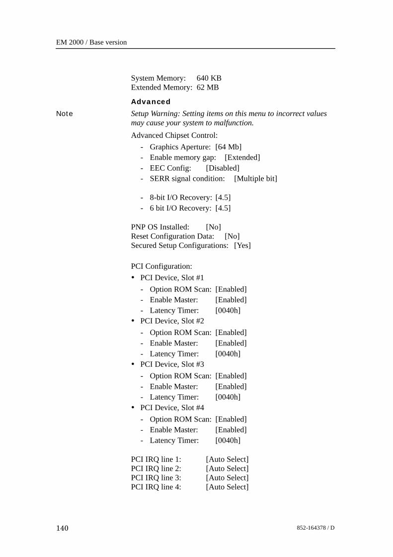
EM 2000 / Base version
140 852-164378 / D
System Memory: 640 KBExtended Memory: 62 MB
Advanced
Note Setup Warning: Setting items on this menu to incorrect valuesmay cause your system to malfunction.Advanced Chipset Control:
- Graphics Aperture: [64 Mb]- Enable memory gap: [Extended]- EEC Config: [Disabled]- SERR signal condition: [Multiple bit]
- 8-bit I/O Recovery: [4.5]- 6 bit I/O Recovery: [4.5]
PNP OS Installed: [No]Reset Configuration Data: [No]Secured Setup Configurations: [Yes]
PCI Configuration:• PCI Device, Slot #1
- Option ROM Scan: [Enabled]- Enable Master: [Enabled]- Latency Timer: [0040h]
• PCI Device, Slot #2- Option ROM Scan: [Enabled]- Enable Master: [Enabled]- Latency Timer: [0040h]
• PCI Device, Slot #3- Option ROM Scan: [Enabled]- Enable Master: [Enabled]- Latency Timer: [0040h]
• PCI Device, Slot #4- Option ROM Scan: [Enabled]- Enable Master: [Enabled]- Latency Timer: [0040h]
PCI IRQ line 1: [Auto Select]PCI IRQ line 2: [Auto Select]PCI IRQ line 3: [Auto Select]PCI IRQ line 4: [Auto Select]
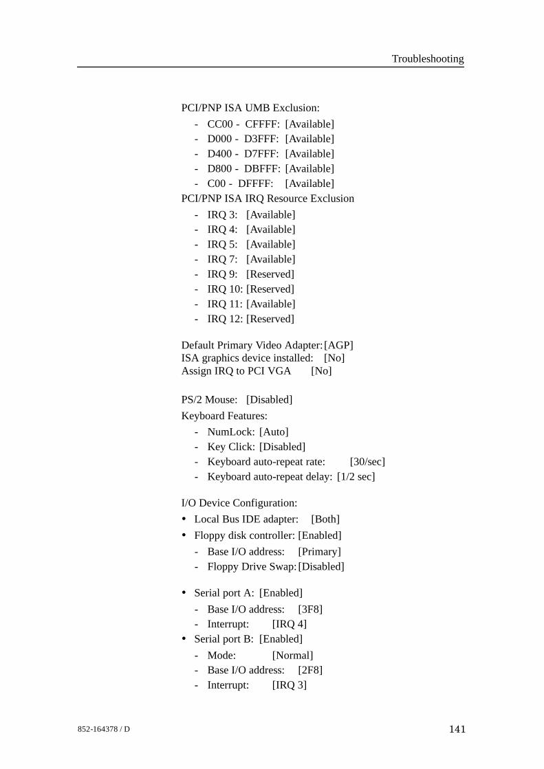
Troubleshooting
141852-164378 / D
PCI/PNP ISA UMB Exclusion:- CC00 - CFFFF: [Available]- D000 - D3FFF: [Available]- D400 - D7FFF: [Available]- D800 - DBFFF: [Available]- C00 - DFFFF: [Available]
PCI/PNP ISA IRQ Resource Exclusion- IRQ 3: [Available]- IRQ 4: [Available]- IRQ 5: [Available]- IRQ 7: [Available]- IRQ 9: [Reserved]- IRQ 10: [Reserved]- IRQ 11: [Available]- IRQ 12: [Reserved]
Default Primary Video Adapter: [AGP]ISA graphics device installed: [No]Assign IRQ to PCI VGA [No]
PS/2 Mouse: [Disabled]Keyboard Features:
- NumLock: [Auto]- Key Click: [Disabled]- Keyboard auto-repeat rate: [30/sec]- Keyboard auto-repeat delay: [1/2 sec]
I/O Device Configuration:• Local Bus IDE adapter: [Both]• Floppy disk controller: [Enabled]
- Base I/O address: [Primary]- Floppy Drive Swap: [Disabled]
• Serial port A: [Enabled]- Base I/O address: [3F8]- Interrupt: [IRQ 4]
• Serial port B: [Enabled]- Mode: [Normal]- Base I/O address: [2F8]- Interrupt: [IRQ 3]
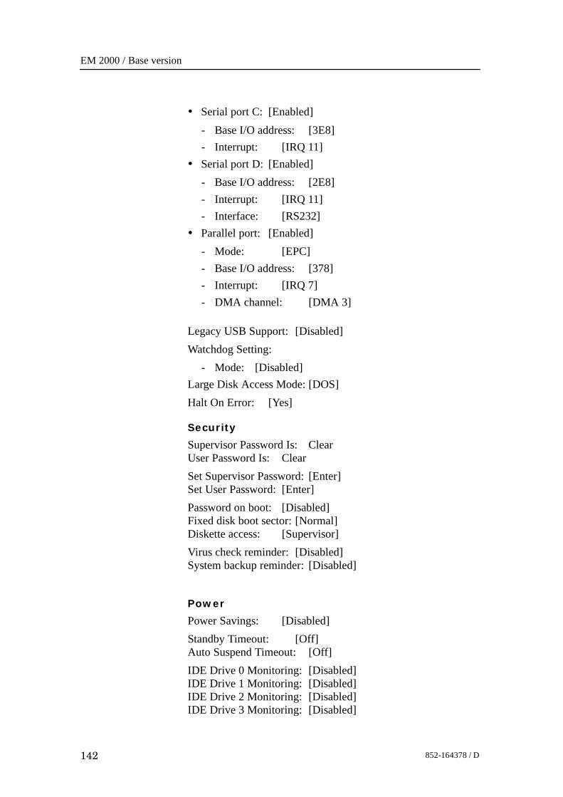
EM 2000 / Base version
142 852-164378 / D
• Serial port C: [Enabled]- Base I/O address: [3E8]- Interrupt: [IRQ 11]
• Serial port D: [Enabled]- Base I/O address: [2E8]- Interrupt: [IRQ 11]- Interface: [RS232]
• Parallel port: [Enabled]- Mode: [EPC]- Base I/O address: [378]- Interrupt: [IRQ 7]- DMA channel: [DMA 3]
Legacy USB Support: [Disabled]Watchdog Setting:
- Mode: [Disabled]Large Disk Access Mode: [DOS]Halt On Error: [Yes]
Security
Supervisor Password Is: ClearUser Password Is: ClearSet Supervisor Password: [Enter]Set User Password: [Enter]Password on boot: [Disabled]Fixed disk boot sector: [Normal]Diskette access: [Supervisor]Virus check reminder: [Disabled]System backup reminder: [Disabled]
Power
Power Savings: [Disabled]Standby Timeout: [Off]Auto Suspend Timeout: [Off]IDE Drive 0 Monitoring: [Disabled]IDE Drive 1 Monitoring: [Disabled]IDE Drive 2 Monitoring: [Disabled]IDE Drive 3 Monitoring: [Disabled]
Troubleshooting
143852-164378 / D
PCI Bus Monitoring: [Disabled]
Boot
Floppy check: [Disabled]Summary screen: [Disabled]QuickBoot Mode: [Disabled]Dark Boot: [Disabled]
Boot Device Priority
Hard Drive:
- SanDisk
- Primary Master
- Bootable Add-in Cards
Removable Devices
- Legacy Floppy Drives
ATAPI CD-ROM Drive
Network Boot
Onboard LAN RPL ROM [Disabled]
Format the Boot drive for SM 2000
• Format the Boot drive for SM 2000 to be a system drive. Theflash disk is mounted as D:
- format D: /s
• Copy the DOS boot files and VXWorks boot files for this SM2000 system
- The DOS files:
- copy AUTOEXEC.BAT D:
- copy COMMAND.COM D:
- copy CONFIG.SYS D:
- The VXWorks files
- copy VXLOAD.COM D:
- copy VXWORKS.ST D:
• Make the directory for DOS commands.
- mkdir c:\dos
EM 2000 / Base version
144 852-164378 / D
• Copy the DOS files that are needed.
- copy COUNTRY.SYS- copy DISPLAY.SYS- copy EDIT.COM- copy EGA.CPI- copy FDISK.EXE- copy FORMAT.COM- copy HIMEM.SYS- copy KEYB.COM- copy KEYBOARD.SYS- copy MODE.COM- copy QBASIC.EXE- copy SETVER.EXE- copy XCOPY.EXE
• Make the directory for BSP programs- mkdir c:\BSP_2000
• Copy the files for the BSP cards.
- copy BBOT.OUT- copy C44A.OUT- copy C44D.OUT- copy C44X.OUT- copy C50.OUT- copy HC.OUT- copy HCT_MON.OUT- copy CALIB.TXT
Replacement procedures
145852-164378 / D
9 REPLACEMENT PROCEDURES
9.1 Introduction
OverviewThis chapter presents the basic procedures for disassembly andreassembly of the replaceable parts in the EM 2000 system.
Caution The Sonar Head should not be opened by unauthorizedpersonnel. We recommend that you contact yournearest Kongsberg Maritime office. When you open theSonar Head, your insurance will no longer be regardedas valid!
EM 2000 / Base version
146 852-164378 / D
Tools requiredA standard tool set is required to perform the removal andreplacement of the modules. This tool set should contain thefollowing tools:• Cabinet key• Standard screwdrivers in different widths and lengths• Standard cross-slot screwdrivers in different widths and
lengths• Allen keys in metric sizes• Philips screwdrivers in different sizes• Pozidrive screwdrivers in different sizes• Flat nosed pliers• Lap jointed pliers• Wire cutters• Soldering iron• Open ended and ring spanners in metric sizes• Adjustable spanners• Socket setThe following expendables are recommended:• Solder• Wire straps in different sizes
Replacement procedures
147852-164378 / D
9.2 Processing Unit procedures
OverviewThe Line Replaceable Units (LRUs) in the EM 2000 ProcessingUnit are:• 4-Ports Serial Line board• Control Processor board (CPU)• Beamformer & Signal Processor (BSP)• Beamformer Interface (BIF)• Fan• MotherboardOther devices:• AC mains fuse and filters• Fuses• Fan drawersThe replacement procedures for these parts are described in thefollowing disassembly and reassembly procedures.The modules that are accessible, are described in this chapter.
Circuit boards and modules
Introduction
The system must be switched off prior to disassembly. Access isgained by opening the top and/or side panel(s) of the ProcessingUnit. How to open the Processing Unit is described under theDisassembly procedure.
Disassembly procedure
1 Remove the mounted cables from the applicable circuitboards.
2 Release the thumb-screws if required.3 Pull the board/unit carefully out.
Reassembly procedure
1 Check links and switches on the new board and compareto the old board.
2 Insert new circuit boards and modules in reverse order.Mount the removed cables and the front covers.
3 Check that the circuit boards and modules have beeninstalled in their correct locations! (Refer to the applicablepictures and drawings).
EM 2000 / Base version
148 852-164378 / D
Fans
Introduction
Two of the fans are mounted on the bottom plate in theProcessing Unit. One is mounted next to the Power Supply.Remember to switch off the system.The system must be switched off prior to disassembly. Access isgained to the wired rack by opening the top panel of theProcessing Unit. How to open the Processing Unit is describedunder Disassembly procedures of the Circuit boards andmodules.
Disassembly procedure
1 When you have reached access to the fan, unscrew it, andremove the cable connected.
2 Replace the fan with a new one.
Reassembly procedure
1 Mount the screws, and put the cables back to their originalplace.
Power Supply
Introduction
How to open the Processing Unit is described under theDisassembly procedures of the Circuit boards and modules.
Disassembly procedure
1 Switch off the circuit breaker.2 Unbolt the unit. It is mounted with four captive-bolts so
they cannot fall out. The nuts and spring washers areaccessible.
Reassembly procedure
The new power supply is replaced by reversing the aboveprocedure.

Datagram formats
149852-164378 / D
10 EM DATAGRAM FORMATSFor information on this topic see own document (160962 EMSeries Datagrams).

EM 2000 / Base version
150 852-164378 / D
11 SYSTEM ADMINISTRATION (UNIX)
Note If you have a SIS operator station please refer to the SISOperator Manual.
11.1 IntroductionThis chapter provides basic reference information useful for theEM 2000 system supervisor. In order to make the most of theinformation provided, you may need some basic knowledge ofthe Unix operating system.
System administration
151852-164378 / D
11.2 Passwords
EM 2000 Installation setupIn order to change the installation parameters on the EM 2000system, you need to enter a password. This password is commonfor all the operators of the EM 2000 system. You willautomatically be prompted to enter the password once you selectEdit enable in the Edit menu.If a password has not been identified, the first attempt to modifythe installation parameters will prompt you to enter a newpassword.If the password is lost, the current password can be deleted bydeleting the following file:$HOME/.eso_system/.esoEM 2000_protection
No special privileges are required to delete this file. Once it isgone, the system will prompt you for a new password next timeyou choose Edit enable.
EM 2000 / Base version
152 852-164378 / D
11.3 EM 2000 File system
IntroductionThe EM 2000 requires a large number of individual files. Someare used for data storage, others for system setup, while someare used to store operator and system configurations. Thischapter lists the various file types and provides briefexplanations.The notation $<name> is an “environment variable”, usuallyspecifying a filsystem directory.
Survey filesDuring a survey, the EM 2000 system will record and store thefollowing file types:• Raw data• Survey dataThe information is stored on the Operator Station harddisk ondedicated data formats defined by Kongsberg Maritime..
Survey data
These are the data files generated by the system. Note that fileswill only be stored if the Survey Format To Disk option ischecked in the window opened by Options -> Logging.These files are used by the post-processing software, and by theSurvey Display program.
Note Unless this data is stored, the Survey Display application willnot work.
Raw data
These are the files containing the raw data retrieved during thesurvey. These files are the most important files collected duringa survey. If you accidentally loose your survey data format files(required by the post-processing software), you can recreatethese files based on the raw data files. Care should be taken tobackup raw data files on a regular basis, using the backupfacilities supplied as an integral part of the system.
Sound speed profilesAll the sound speed profiles are stored as separate files indirectory specified by the environment variable.
System administration
153852-164378 / D
$SHAREDHOMEThe files have extension *.asvp
Absorption coefficient fileThe absorption coefficient file contains number pairs ofabsorption coefficients and corresponding depths. Thecoefficients are integrated during loading to the echo sounderand the integrated value is used. The file is namedabsorption.coef and is stored in directory:$SHAREDHOME
Workstation I/OWhen you define the use of the Operator Station’s serial lines,the setup information is stored in the following file:$HOME/.eso_system/esoSetup.serial
Echo sounder parametersThese are the files determining how the current echo soundersystem is set up. The system uses separate files for runtime andinstallation parameters.
Installation setup
The installation setup information is saved in the following file:Every time you save this file, a backup file is generatedautomatically. This file is named:where:
yyyy=yearmm=monthdd=dayhh=hourmm=minute.
You can also save the setup files with other names you chooseyourself. You can then pick any name, but you must keep theextension as “.installation”. The extension is addedautomatically if you only specify the file name.
Runtime setup
The runtime setup information is saved in the following file:
esoEM2000Setup.runtime
EM 2000 / Base version
154 852-164378 / D
Every time you save this file, a backup file is generatedautomatically. This file is named:where:
yyyy=yearmm=monthdd=dayhh=hourmm=minute.
You can also save the runtime files with other names you chooseyourself. You can then pick any name, but you must keep theextension as “.runtime”. The extension is added automatically ifyou only specify the file name.
Echo sounder status
The information in the Status Field in the Launchpad is stored inthe following file:$HOME/.eso_system/esoSetup.status
IP addresses, ports and datagrams
The IP addresses for the various items in the system, the portsused for the various applications, and the datagram distributionare collected in the following file:$HOME/DPC.addresses.<host>where <host> is the name of the Operator Station.You may modify the contents of this file by using the Options-> Datagram subscriptions choices on the Launchpad.The datagrams available are listed in the following file:$HOME/.eso_system/esoSetup.datagramsThis is a static file, and will only be used by the system.
NMEA 0183
The information for the NMEA 0183 depth serial line is storedin the following file:$HOME/.eso_system/esoSetup.serial
BIST filesWhen you run the built-in test applications, the results displayedin the output area in the BIST window may be saved to disk.The file is created with the following location and file name:$HOME/.eso_system/BISToutput
System administration
155852-164378 / D
Every time you save the information, the old file will bereplaced. The information is stored in ASCII format.
LogfilesEach application in the EM 2000 system issues report and errormessages when required. These messages are collected inlogfiles.The size of the current logfile is monitored by the system. If itexceeds 8Mb, a warning dialogue pops up recommending a resetof the file. The actual reset is done using the File->ResetLogfile option, as instructed in the popup dialogue.When you reset the logfile using the File -> Reset logfilecommand on the Launchpad, you may create a backup copy ofthe logfile. The backup is named:$HOME/.eso_system/esoLogfile.yyyy_mmdd_hhmmwhere:
yyyy=yearmm=monthdd=dayhh=hourmm=minute.
In most cases you do not need to create backup copies of thelogfile, since errors and warnings are logged to the surveylogfiles during active surveying.In addition to this logfile, the errors and warnings issued duringa survey are saved on a separate file for the active survey. Thisfile is only created while logging takes place. The file is:$PROCHOM/<survey>/esoLogfilewhere <survey> is the chosen name for the active survey.
Operator configuration filesThese are the individual files containing the operator specifiedwindow layouts and desktop workspaces for the programssupervised by the EM 2000 Launchpad.
Default window layout
Each operator can define a preferred window and workspacelayout, and then use the Window Layout -> Save Operator’sLayout command on the launchpad’s main menu to save thisinformation. The name of the file will be:
EM 2000 / Base version
156 852-164378 / D
$HOME/.eso_system/esoEmX_config.<operator>where <operator> is the current operator of the system, asdefined in the Launchpad’s Survey field (below the programicons).The default window layout is:$HOME/.eso_system/esoEmX_config
List of known operators
The list of the operators known to the system is stored in thefollowing file:$HOME/.eso_system/esoSetup.operators
User preferences
All the preferences you define during the survey are stored in aseparate file.$HOME/.eso_system/esoSetup.launchpadThis file is created using the Options -> User preferencescommand on the Launchpad’s main menu.
Survey jobsThese are the files generated by the Survey Display’s Planningmodule. All these plans are located in the following directory:$SHAREDHOME/<job name>.asciiplan
TOC filesThe TOC (Table of Contents) files are created automaticallywhen you select the Generate Tape TOC operation in the FileAdmin window.Each TOC file contains a list of oll the files on the tape. This isnormally all the files used for a specific survey, but in general itcan be any file types recognized by the File Admin utility.The TOC files can be named manually, or they can be assigneda name automatically. This name is then defined based on thecurernt date and time with extension *.TOC.The files are stored in the following directory:$HOME/.eso_system/
System administration
157852-164378 / D
11.4 File formats
IntroductionThe main files are described in this chapter, but the header filesthat follow the system are only referred to and must be inspectedby listing the header file of current interest or by checking thecomputer display.
Survey format and I/O libraryThe Survey Format (SF) files are the key files of theKongsberg Maritime workstation systems. The files are locatedin the $PROCHOME directory. An I/O library fromKongsberg Maritime is supplied to the users who wish to accessthe data themselves. You can then install the I/O librarywhereever it fits for your development. Header files andlibraries are available.The SF is a Kongsberg Maritime defined format that fits for allKongsberg multibeam echo sounder data, and for the EA 500and EK 500 single beam echo sounders. The data is converteddirectly to this format if a Kongsberg Maritime logging systemis used. As the lines are run, the raw data is fed into thehandleMessage or handleEmX filter and stored correctly onthe $PROCHOME/<SurveyName> directory, while thesurvey.lines file on the same directory is updated withinformation about the same line.
The survey format
Introduction
This is the Kongsberg Maritime workstation processing formatthat applies to all multibeam echo sounders and also to somesingle beam echo sounders. The format is used in otherworkstation products in addition to Neptune, such as Merlin,Poseidon and Triton.The format is based on indexed files. For each line there is anindex file which holds some common index data for each ping.The files handled by the index file are:1 Depth file2 Sonar Image file3 Classification fileThe following files have been defined as system administrationfiles:
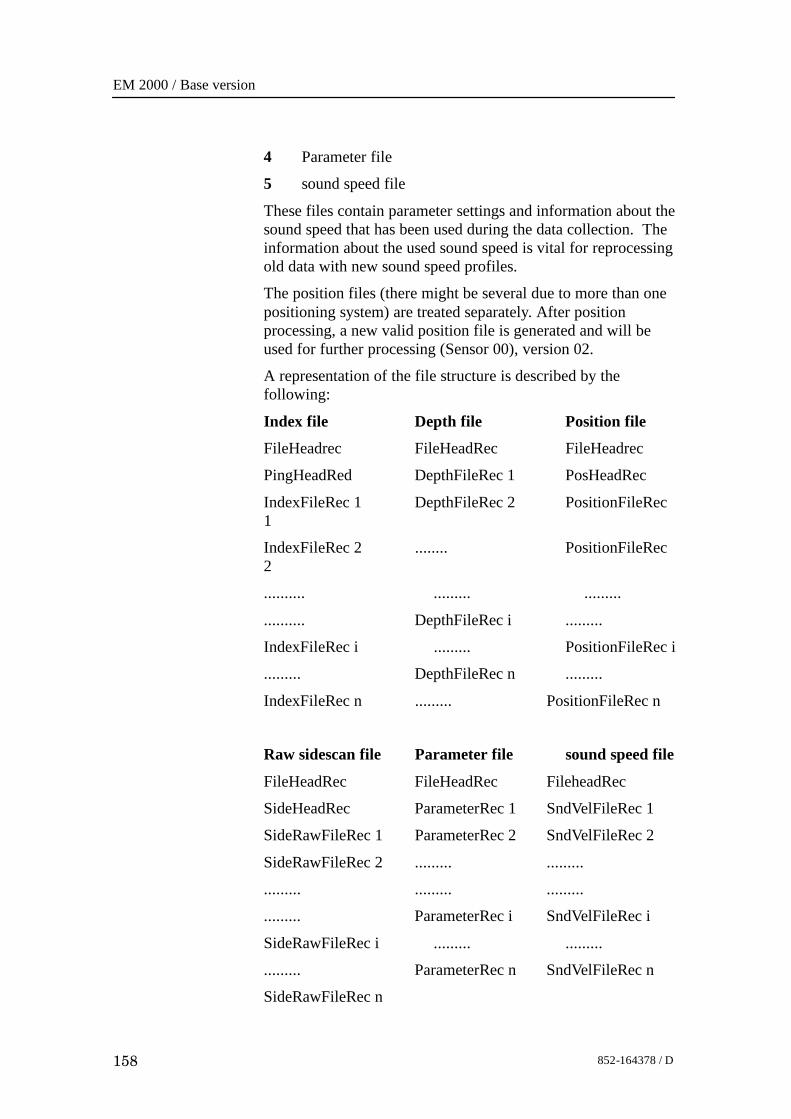
EM 2000 / Base version
158 852-164378 / D
4 Parameter file
5 sound speed file
These files contain parameter settings and information about thesound speed that has been used during the data collection. Theinformation about the used sound speed is vital for reprocessingold data with new sound speed profiles.
The position files (there might be several due to more than onepositioning system) are treated separately. After positionprocessing, a new valid position file is generated and will beused for further processing (Sensor 00), version 02.
A representation of the file structure is described by thefollowing:
Index file Depth file Position file
FileHeadrec FileHeadRec FileHeadrec
PingHeadRed DepthFileRec 1 PosHeadRec
IndexFileRec 1 DepthFileRec 2 PositionFileRec1
IndexFileRec 2 ........ PositionFileRec2
.......... ......... .........
.......... DepthFileRec i .........
IndexFileRec i ......... PositionFileRec i
......... DepthFileRec n .........
IndexFileRec n ......... PositionFileRec n
Raw sidescan file Parameter file sound speed file
FileHeadRec FileHeadRec FileheadRec
SideHeadRec ParameterRec 1 SndVelFileRec 1
SideRawFileRec 1 ParameterRec 2 SndVelFileRec 2
SideRawFileRec 2 ......... .........
......... ......... .........
......... ParameterRec i SndVelFileRec i
SideRawFileRec i ......... .........
......... ParameterRec n SndVelFileRec n
SideRawFileRec n
System administration
159852-164378 / D
Survey format I/O library
The I/O sub-routine library can be used by a company orinstitution who have bought a license for a Kongsberg Maritimeworkstation product. It can also be distributed by the KongsbergMaritime customer to others after agreement betweenKongsberg Maritime and the institution or company.Maintenance and help with the library and files are given tothose who have maintenance contract with Kongsberg Maritime.
The Survey format coordinate system
The coordinate system of the vessel has an x-axis along theships keel pointing forwards from the origin of the ship. They-axis points to starboard, and the z-axis points straight downgiving the depths as positive values increasing with depth.This generates the right-hand coordinate system on board theship. Positive rotation around the axis is defined by theright-hand rule, giving a positive rotation of angles in thehorizontal plane in the same way as the gyro rotates positively(Clockwise as seen from above the ship).The data that is logged on files is in latitude/longitudecoordinates. The data is represented by a 4-byte integer that hasthe following resolutions:Latitude :
2*10E7 decimal degrees per number unit (+90 to -90degrees).
Longitude:1*10E7 decimal degrees per number unit (+180 to -180degrees).
Depths are treated with centimetre resolution in the EM 2000system, and represented in this resolution on the XYZ files.
Use of the Kongsberg Maritime I/O library
Introduction
The Kongsberg Maritime I/O library consists of two differentparts. One part is intended to be used by those who want to fittheir own data into Kongsberg Maritime’s Survey Format (SF)file format. The modules supported for this use are msgSim andhandleMessage. The handleMessage takes its input data fromthe logging program (Mermaid/Merlin) or from msgSim. Theother part is intended to be used by those who want to useSurvey Format data. This part of the library is called RWlib(Read and Write library). All routines in the library return aninteger as return parameter. This parameter is negative ifsomething went wrong or the data returned are not valid.
EM 2000 / Base version
160 852-164378 / D
Message simulator
The message simulator (msgSim) simulates messages from thelogging system by reading one or more raw data files, puttingthe message length in front of each message and writing it tostdout. If the messages are separated on different data files, thefiles containing the depth data message must end with .dpt,position data with .pos, sidescan data with .rss andstart/stop/parameter data with .inf. The module also handles thesituation when all messages are collected in one file. All ofthese data files must only contain valid, complete messages andnothing else.
Message handling
Messages from Mermaid/Merlin or msgSim may be ’piped’ intohandleMessage. This module reads the messages from stdin,decodes them into survey format and writes them to file. Thefiles written are:• position files (.pos)• depth files (.depth)• sidescan files (.sidescan)• parameter files (.para)• sound speed files (.svel)• index files (.ind).The name of the new file starts with the line number, anunderscore, the date of the start telegram, an underscore, thetime, an underscore, sensor number, an underscore, versionnumber and the extension.Example:0183_19921031_155630_00_01.depthThe module starts decoding and writing when a start telegramarrives and stops when a stop telegram arrives. If sidescan datais to be handled, depth data must be present, and if the data is tobe used with ”near real time” visualization (i.e. Merlin), positiondata must also be present. For information on how to runhandleMessage, see the section ”Command references”.
Library calls
Introduction
The library is written in the ANSI “C” programming language.The definition and prototyping is done in the *.h files:• readWriteFile.h
System administration
161852-164378 / D
• SurveyLines.h
• newFormat.hThe return structures that you need to know about are found inthe newFormat.h file. This file is documented internally in thefile, while the other *.h files not are intended to be read, justincluded to supply you with the structures required for some ofthe calls. These calls are described here, and the prototyping isfound in the above listed header files.
Writing new files
For writing new files in SF the library libRW is supported. Withthis library you can open, write and close new files in SF.Before a file (of any type) can be written, it must be opened bythe appropriate open routine for this file type. The inputparameters for these routines are:• file directory,• generic file name,
• sensor number (set to 0->zero)• type specific header,• a comment and a description of the process which created the
file.In addition file handler newFilePnt must be supported for eachfile (except for opening the index file) and one common writehandler. E.g. this write handler is used for writing indices tofiles. To write new records to file, a set of writing routines aresupported. All those writing routines have their specific recordformat, their file handler (except for writing pings) and thecommon write handler as parameters. When depth data orsidescan data is written, it must be specified which sounder (portor starboard for dual system or single for single system) the datacomes from. To close the file (except the index file which isclosed with a specific routine) the routine closeNewFile is calledwith the file handler as input.
EM 2000 / Base version
162 852-164378 / D
All data are written to file in the native format (little or bigEndian) in which the program is running. The index file (withping data) is written every time the ping number changes. Thisis done automatically in writeDepth or writePing, which meansthat these routines must be called in order to let the index andping records be written (ping number must be supplied andproperly changed if not present in the raw datagram). Date andtime must also be supplied for each record (ping and position)so that it will be possible to index a ping from position throughdata and time. When the index file is written, all indices arewritten including those for sidescan and position. As sidescandata only are accessible through the index file, all calls to eitherwriteDepth or writePing must be made. Position data, on theother hand, may either be accessed via index (for ”near realtime”) or via time. But in order to make indices for the positiondata correct, all data must be written in time sequence. Thepositions are also filtered for coarse jumps (i.e. more than onedegree) and flagged accordingly before they are written.Available routines are described in the following paragraphs.
Open files
newIndexFile: Open and init index file
(IN: writeHandler, directory, fileName, sensor,pingHeader, comment, process)
newPosFile: Open and init position file
(IN: fileHandler, writeHandler, directory, fileName,sensor, posHeader, comment, process)
newDepthFile: Open and init depth file
(IN: fileHandler, writeHandler, directory, fileName,sensor, comment, process)
newSideFile: Open and init sidescan file
(IN: fileHandler, writeHandler, directory, fileName,sensor, sideHeader, comment, process)
newSvelFile: Open sound speed file
(IN: fileHandler, writeHandler, directory, fileName,sensor, comment, process)
newParaFile: Open parameter (start/stop/parameter) file
(IN: fileHandler, writeHandler, directory, fileName,sensor, comment, process)
Write files
writePos:-- Write position data to file
(IN: fileHandler, writeHandler, positionRecord)
System administration
163852-164378 / D
writeDepth: Write depth data to file (and possible also index and ping)
(IN: fileHandler, writeHandler, sounder, depthRecord)writeSidescan: Write sidescan data to file
(IN: fileHandler, writeHandler, sounder, sidescanRecord)writePing: Set current ping data, write ping and index data to file
(IN: writeHandler, sounder, pingRecord)writeSvel: Write sound speed data to file
(IN: fileHandler, writeHandler, soundVelRecord)writePara: Write parameter data to file
(IN: fileHandler, writeHandler, parameterRecord)Close filescloseNewFile: Close a file
(IN: fileHandler)closeIndexFile: Write last index/ping to file (if necessary), close index
file
(IN: writeHandler)
Reading and updating survey data
For those who only want to read or update data on SF, thelibrary libRW is supplied. With this library you can open, read,copy, update and close the files containing SF data.Before anything can be done with a file, it must be opened bythe appropriate opening routine. These routines have theparameters:1 file mode (r or r+)2 directory3 file name4 sensor number (set to 0)5 file version number as inputIn addition a file handler must be supported for each file. Forthe index file an index handler must also be supported. It isthrough this index handler that depth, sidescan and (for ”nearreal time”) position data are accessible. The different openingroutines then return some type specific data (e.g. a file headerand number of record). To open a file for reading, set file modeto r and for updating set file mode to r+.If the data is written on a machine with little Endian and read ona machine with big Endian format (or vice versa), it isautomatically swapped when read, or updated. If the file iscopied, then it is always copied to the native format of themachine the program is running on.
EM 2000 / Base version
164 852-164378 / D
Note Compressed data can not be transferred between little Endianand big Endian machines.
Compressed data can not be transferred between little Endianand big Endian machines.
The data can be accessed in several different ways. Ping data,position data, sound speed data and parameter data are accessedvia an index number which starts at 0 (zero) and goes up to thenumber of records (minus one) for each file. Depth data andsidescan data are accessed via the file index. This index is setwith the setFileIndexno routine. If the depth and sidescan datawere produced by a dual echo sounder system, the port andstarboard can be accessed via the port and stb parameters; forsingle echo sounder system, the sing parameter is used.
To get an interpolated position for a ping, one must first call theroutine initPosInter. This routine incudes an index to the firstposition and number of positions as input parameters. This isbecause all indexing on a file within a region is based on theindices from the position file. The routine uses a handlerposSearchPnt and returns the first valid ping index and numberof indices within the positions. These parameters should then beused in the loop to access the ping, depth and sidescan data.
To get a ping with its position the routine getPingPos is used.This uses the parameter indexHandler set by setFileIndexno.You may also specify the maximum legal difference in time andin distance from the ping to the two nearest positions. If youonly want ping data at a specific delta distance, this may also beset. If the routine returns with a negative number, no validposition exists for this ping. When finished, freePosInter iscalled.
To update a file, the file must be opened with file mode = r+.Then all the update routines can be used. Access through theindex handler to depth and sidescan files must still be used.When the updating is finished, updateHeader must be called toset the right time and process for file updated. If you want tochange other data in the files than flags, the file should becopied (with copyFile) before it is updated. The routinecopyFile has as input parameter the file handler and the newdirectory, and it returns the new file version number.
To make a new position file from several position files(combine), the general file header must be copied withcopyHeader. Then the copied file (header) must be openedwith openPosFileAppend and position can be written (insequence) with updatePostion.
System administration
165852-164378 / D
There are also some convenience routines to update flags forposition, ping and depth data. These routines read the data,check if some flags are changed and if so, write the changeddata back. Modules that keep original survey data structures inmemory, should use the ordinary update routines instead. It ishowever strongly recommended that you keep track of whatflags (e.g. one variable that tells whether some of the depth flagsfor a ping are changed) that are changed, in order to minimizeinput/output. When depth flags are updated only those flagswhich are not equal NaN (Not a Number) are updated.The module does also (for the time being) contain some routinesto transform across- and along-data for each beam to eitherlatitude and longitude or to UTM and to calculate the distancebetween two positions. Supplied routines are described in thefollowing paragraphs.
Open files
openIndexFile Open index file
IN: fileHandler, indexHandler, fileMode, directory,fileName, sensor, versionNumber,OUT: pingHeader, sounderSystem, numbOfPing
openPosFile Open position file
IN: fileHandler, fileMode, directory, fileName, sensor,versionNumber,OUT: posHeader, numbOfPos
openDepthFile Open depth file
IN: fileHandler, fileMode, directory, fileName, sensor,versionNumber
openSideFile Open sidescan file
IN: fileHandler, fileMode, directory, fileName, sensor,versionNumber,OUT: sideHeader
openSvelFile Open sound speed file
IN: fileHandler, fileMode, directory, fileName, sensor,versionNumber,OUT: numbOfSvel
openParaFile Open parameter file
IN: fileHandler, fileMode, directory, fileName, sensor,versionNumber,OUT: numbOfPara
EM 2000 / Base version
166 852-164378 / D
openPosFileAppend Open position file for append
IN: fileHandler, directory, fileName, sensor,versionNumber, posHeader)
Reading data
setFileIndexno Set index and get ping data
IN: fileHandler, indexHandler, pingIndex,OUT: pingRecord
getDepth Get depth data
IN: fileHandler, indexHandler,OUT: singDepthRecord, stbDepthRecord,portDepthRecord
getSidescan Get sidescan data
IN: fileHandler, indexHandler,OUT: singSidescanRecord, stbSidescanRecord, portSide-scanRecord
getPosition Get position data
IN: fileHandler, posIndex,OUT: positionRecord
getManyPos Convenience routine to get manypositions
IN: fileHandler, fromPosIndex, numbOfPos,OUT: positionRecords
getSvel Get sound speed data
IN: fileHandler, svelIndex,OUT: soundVelRecord
getPara Get parameter data
IN: fileHandler, paraIndex,OUT: parameterRecord
getPosIndDateTime Get position indexes from date and time
IN: fileHandler, totNumbOfPos, fromDate, fromTime,toDate, toTimeOUT: fromPosIndex, numbOfPos
initPosInter Initiate for accessing interpolatedpositions for ping
IN: positionFileHandler, indexFileHandler, posSearchPnt,posHeader, fromPosIndex, numbOfPos, totalNumbofPing,
System administration
167852-164378 / D
OUT: fromPingIndex, numbOfPinggetPingPos Get ping with interpolated position
IN: indexFileHandler, indexHandler, posSearchPnt,pingIndex, deltaDistance, maximumDistance, maximumTimeDifference,OUT: pingRecord, positionRecord
freePosInter Free data for position interpolation
IN: posSearchPntgetManyIndex- Get noPing pings from fromPing
IN: indexFileHandler, fromPing, noPing,OUT: indexes
getNoPing- Get number of ping in file
IN: indexFileHandler,OUT: noPing
getInterPos Interpolate position from time and date
IN: positionFileHandler, indexFileHandler, posHead,maxDist, maxTimeDiff,OUT: newPos
getPosList Get position data into position list
IN: positionFileHandler, posHead, fromPos, noPos,deltaDist, maxDist,OUT: pingPosList
getPingList Get position data into ping list
IN: pingHead, posSearch, fromPing, noPing, deltaDist,maxDist, maxTimeDiff,OUT: pingPosList
getFromNoOfPing Get fromping and no of pings for pingsthat are between two valid positions
IN: positionFileHandler, indexFileHandler, fromPos,noPos, totPing,OUT: fromPing, noPing
flagPosJump Mark all position with pos_jump_flagwhich are outside a given range from themedian of the surrounding positions
IN: posHead, noPos, pos, medianFilterType, maxDist
Copy file
copyFile Copy file
IN: fileHandler, directory,
EM 2000 / Base version
168 852-164378 / D
OUT: versionNumbercopyHeader Copy general file header
IN: fileHandler, directory,OUT: versionNumber
Update fileupdatePing Update ping data and set index
IN: fileHandler, indexhandler, pingIndex, pingRecordupdateDepth Update depth data
IN: fileHandler, indexHandler, singDepthRecord,stbDepthRecord, portDepthRecord
updateSidescan Update sidescan data
IN: fileHandler, indexHandler, singSidescanRecord, stbSidescanRecord, portSidescanRecord
updatePosition Update position
IN: fileHandler, posIndex, positionRecordupdateHeader Update file header after updating file
IN: fileHandler, process, comment
Update flags
updatePosFlag Update position flag
IN: fileHandler, posIndex, positionFlagupdatePingFlag Update ping flag and set index
IN: fileHandler, indexHandler, pingIndex, pingFlagupdateDepthFlag Update depth flag for current index
IN: fileHandler, indexHandler, singDepthFlagList,stbDepthFlagList, portDepthFlagList
Close filecloseFile Close a file
IN: fileHandler
Convenience routines
Some routines has been developed to make life easier for theprogrammers. These functions are listed below.
TransformtoLL Transform each beam to latitude and
longitude
IN: positionRecord, posHeader, gyroHeading,depthRecord,OUT: latLongPositions
System administration
169852-164378 / D
toUTM Transform each beam to UTM
IN: utmSone, positionRecord, posHeader, gyroHeading,depthRecord,OUT: utmPositions
getDiffDist Calculate distance between to positions(in centimetres)
IN: fromPositionRecord, toPositionRecord, posHeaderOUT: distance
calcDirection Calculate the direction from one positionto another (in milli-degrees)
IN: fromPositionRecord, toPositionRecord, posHeaderOUT: direction
Header filesFor each file there is a description on what it contains. Thedocumentation is on the header file itself, and the user shouldconsult this file. It is found in the IO library distribution.For each file there is a description on what it contains. Thedocumentation is on the header file itself, and the user shouldconsult this file. It is found in the IO library distribution.readWriteFile.h Handlers and prototypes for
readWriteFile.cnewFormat.h Definition of survey format.process.h Process id. descriptiondatum.h List of datumscdefine.h Definitions of some C programming
definitions used in the programs.general.h Definition of some general structures that
are used several places in the code.
SurveyLines libraryThis file is important for all the processing. It includes all thelines of the survey, and identifies which versions are the mostrecent. The file is binary and is located on the$PROCHOME/<SurveyName> directory.The file survey.lines is an index of all existing SF data files oncurrent directory. The file current.line identifies the linecurrently being processed. These two files must be updated bythe modules writing or updating SF files. All modules readingSF files get a list of existing survey format files by reading thesurvey.lines file. The sensors that exists for the different linesare also listed on a specific file. This is the line.sensors file. Inaddition a file called adm.data contains the sensors of thesurvey with their name and their id numbers.
EM 2000 / Base version
170 852-164378 / D
Writing and updating
The following routines are supplied:
int SlAdd (s110FileType ioFileType /* IN: SL_SURVEY_L or SL_CURRENT_L */
char *dir, /* IN: Directory name */char *prefix, /* IN: File name prefix */SlsurveyFileType survFileType /* IN: SL_POS, SL_INDEX, SL_DEPTH,or
SL_SIDESCAN */int version, /* IN: File version */ProDescType lastProc /* IN: Process identification */)
This function adds a new record to the survey.lines file. If arecord for the directory/file name prefix combination of currentinterest already exists, this record is updated and no new recordis added. For current.line SlAdd has the same functionality asfor survey.lines, except that when a new record is added, theprevious record is deleted.
int SlUpdate (SlIoFileType ioFileType, /* IN: SL_SURVEY_L or SL_CURRENT_L */char *dir, /* IN: Directory name */char *prefix, /* IN: File name prefix */SlSurveyFileType survFileType /* IN: SL_POS, SL_INDEX, SL_DEPTH,or
SL_SIDESCAN */int version, /* IN: File version */ProDescType lastProc /* IN: Process identification */)
This function is equal to the SlAdd function, except that thecurrent directory/file name prefix combination must exist. Ifthe new version number is lower than the version number on thesurvey.lines file, then the datafiles (.pos, .ind, .depth, or.sidescan) with version number higher than the new versionnumber will be deleted.
int SlDelete(
System administration
171852-164378 / D
SlIoFileType ioFileType, /* IN: SL_SURVEY_L or SL_CURRENT_L */
char *dir, /* IN: Directory name */
char *prefix, /* IN: File name prefix */
SlSurveyFileType survFileType, /* IN: SL_POS,SL_INDEX,SL_DEPTH, orSL_SIDESCAN */
ProDescType lastPro /* IN: Process identification */
)
Delete a survey format file by setting the version equal to 0.The record is deleted in the survey.lines file. The datafile (.pos,.ind, .depth, or .sidescan) will be deleted.
int SlDeleteLine(
SlIoFileType ioFileType, /* IN: SL_SURVEY_L or SL_CURRENT_L */
char *dir, /* IN: Directory name */
char *prefix, /* IN: File name prefix */
ProDescType lastPro /* IN: Process identification */
)
Deletes all survey format files for a line by setting the versionsequal to 0. The datafiles (.pos, .ind, .depth, and .sidescan) willbe deleted and the file [<dir>/]<prefix>_00_01.para will bedeleted
Reading
The following functions return information in a SlList structure(See the SurveyLines.h file for information about the structure).The following routines are supplied:
SlList *SlCreateList (
SlIoFileType ioFileType, /* IN: SL_SURVEY_L or SL_CURRENT_L */
)
Function for reading survey.lines and current.line. SlCreateListreturns a SlList structure.
EM 2000 / Base version
172 852-164378 / D
int SlUpdateList (SlIoFileType ioFileType, /* IN: SL_SURVEY_L or SL_CURRENT_L */SlList *ioList /* IN: Pointer to structure from the
SlCreateList function */)
SlUpdateList updates an existing SlList structure. UseSlCreateList once to create the list. Then call SlUpdateListrepeatedly to get information on changes made to thesurvey.lines or current.line.
Header files
This is where the programmers can find the definitions of thestructures of this library. The actual header files are:SurveyLines.h Survey line and current line structures.
lineSensors.h Structures and routines for theline.sensors file.
Administration file I/O
File format
The adm.data file contains the names of the different sensors.The file is an ASCII file named where for each sensor thefollowing data are written:sensor <sensorType1> <N1> <name1>sensor <sensorType2> <N2> <name2>sensor <sensorType1> <N3> <name3>where Nx is the sensor number on the Survey Format files, andnamex is the name of the sensor. The sensorTypex is positionor depth. This is when more than the usual EM sensor exists.The Merlin logging system will build this file and thesurvey.lines file automatically, and the default EM sensor isgiven by:sensor position 0 undefined
Reading
To read the file, the following routine is called:AdReadAdm ( EvHandler *evHand )And to fetch the sensors read:AdGetSensors ( int *noSensors, SensorPnt *snrPnt )

System administration
173852-164378 / D
Structures and files
The structures are defined in the adm.h file.
EM 2000 / Base version
174 852-164378 / D
11.5 Survey Predefined Files
IntroductionWhen you define and run a survey, you will always needinformation describing basic data or set-up, such as:• projection data• user defined colours• user defined show/hide settings• coastline contours• course deviationThe Survey Predefined Files function allows you to build a setof templates to hold this kind of information.
File locationsThe Survey Predefined Files are located in the$SHAREDHOME directory. In this directory, you can createsubdirectories defining specific survey types, where the type canbe defined by your own choice. You can for example create setsof files to match specific bottom conditions or geographicallocations.The result may be (for example):$SHAREDHOME/Oslofjord/*.*$SHAREDHOME/Mercator_30_degrees/*.*In order to create the file structure, and to copy in the files youwish to use, you need to open a terminal window on yourOperator Station and use the standard Unix commands.→ Refer to the applicable instruction manual(s) for a description
of the terminal window and the Unix commands.
Using the Survey Predefined FilesWhen you define a new survey using the options on the EM2000 launchpad, you are asked which of the Survey PredefinedFiles you will use. When you select any of the templates on thelist, the files in that directory are copied over to the surveydirectory on $PROCHOME.
System administration
175852-164378 / D
Scope and purposeThis document defines the interfaces and use of the componentProjection. The purpose with the document is to describe howthe component interfaces with other components, and how thecomponent is to be used.
Projection overviewEach and every survey should have a well defined projection.The Kongsberg Maritime Software will use the definedprojection in all geographic displays and in many otherprograms where a projection is needed.There are three major different ways to define a projection inthe Kongsberg Maritime Software:1 You have full access to the library PROJ.4 from USGS.2 You can give Kongsberg Maritime the source code (in
“C”) to his preferred projection, and make that projectiona permanent part of all Kongsberg Maritime Software.
3 You can program your own projections into the sharedlibrary (libsharedProj.so) which is used in all KongsbergMaritime Software. A template of the source code issupplied by Kongsberg Maritime.
It should be noted that Kongsberg Maritime knows nothingabout what goes on inside your projection routines. Some ofthese routines may contain datum transformations which shouldbe known to the system operator.
Projection protocolYou should for each and every survey define your preferredprojection. The projection used in a survey is defined in the file$PROCHOME/<survey>/projection.dataThe first word in the first line defines which projection to use.The file may look like this:1 If the first word is “RijksDriehoksnet”, the preferred
projection for the Netherlands is used.2 If the first word is “utm”, a UTM-projection is used.
Setting the UTM zone is however a little tricky:utm0 30 3If the file looks like the above, UTM zone 31 is selected.The number 3 is the longitude.

EM 2000 / Base version
176 852-164378 / D
3 If the first word is “sharedlib”, the projection from theshared library libsharedProj.so is used
4 If the first word is “user_defined”, a user definedprojection from the USGS PROJ.4 library is used.The file $PROCHOME/<survey>/projection.data maythen look like this:user_defined defaultProjections:proj1This means that the user defined projection using PROJ.4is found in the file $PROJ_LIB/defaultsProjections andthat the setup for the projection is taken from <proj1>.The file $PROJ_LIB/defaultsProjections may look likethis:(which is standard PROJ.4, ref. [1], [2] and [3]):<proj1>proj=sterex_0=155000y_0=463000k=0.9996lat_0=52.156160556lon_o=5.387638889<proj2>proj=utmzone=31
5 If the first word is “GK_AUSTRIA”, the preferredprojection for Austria is selected. There are 16 parameterswhich controls this projection and they are all kept in thesame file. These 16 parameters must be in the specifiedorder in the file, the rest of the file is comments. As wecan see this projection performs a datum transformationfrom WGS 84 to Bessel (Europe) prior to the projection.The projection itself is a Gauss-Krüger.$PROCHOME/<survey>/projection.data may look likethis:GK_AUSTRIA-563.9-82.3-463.44.474.851.884.466377397.155299.15281285
System administration
177852-164378 / D
16.3333333333336378137.0298.2572235630-5000000500! Line1: GK_AUSTRIA tells Simrad Software! to use Gauss-Kruger for Austria.! Transformationsparameter! für die Umwandlung von WGS84-Koordinaten! nach Gauss-Krüger-Koordinaten bezogen! auf das Datum MGI! Zeile 1: Translation in x [m]! Zeile 2: Translation in y [m]! Zeile 3: Translation in z [m]! Zeile 4: Maßstab! Zeile 5: Rotation in x [”]! Zeile 6: Rotation in y [”]! Zeile 7: Rotation in z [”]! Zeile 8: große Halbachse [m]! Nutzersystem (z.B. Bessel)! Zeile 9: Abplattung Nutzersystem! (z.B. Bessel)! Zeile 10: Zentralmeridian Nutzersystem! (z.B. Bessel)! Zeile 11: große Halbachse [m] WGS84! Zeile 12: Abplattung WGS84! Zeile 13: Zuschlag Rechtswert! Zeile 14: Zuschlag Hochwert! Last line: Fixed height used in! projections.
NotesThe setup of the projection is quite important to do right whichmeans that this should be done by qualified persons only. In theNeptune/Survey Display system it is possible to set up defaultsurveys that you can use as templates for new surveys. Thesedefault surveys can then be set up with the correct projectionsand given names which makes it easy for the operator to choosea default survey of the correct type.There is already a file $PROJ_LIB/defaultsProjections which isin use if some of the standard default surveys are used.
EM 2000 / Base version
178 852-164378 / D
11.6 Dynamic Projection Library
IntroductionThe purpose is to describe how the component interfaces withother components and how the component is to be used.
OverviewThere need to be defined a shared library where the customercan implement his own projection routines to use withKongsberg Maritime’s Graphic System. This shared library willthen be a permanent part of all graphic windows.
Dynamic projection library definitionsIn the graphic system today you can set projection and someprojection parameters in the file$PROCHOME/<survey>/projection.data.This file will also be used when you specify that projectionsshall be taken from the shared library libsharedProj.so. Theshared library for customer defined projections,libsharedProj.so, must be put somewhere where the loaderwill find it at startup, /usr/lib/libsharedProj.so.
Dynamic projection library protocolWhen you wish to use a projection defined in the shared library,the first line in the file$PROCHOME/<survey>/projection.data must look like this:
sharedlib 5The number (here: 5) is defined by you.When the program (i.e. Survey, Merlin, GridDisplay) starts, itwill look for the file$PROCHOME/<survey>/projection.data. When it finds theword sharedlib as the first word in the file, the next word isread as an integer which identifies which projection will beused.
The initUserProjection routine is then called with this numberas a parameter. This enables you to do additional initialisation tothe projection. Since only the first line in $PROCHOME/<survey>/projection.data is used by the system, you canfreely use the rest of this file for additional parameters to beread at startup time.
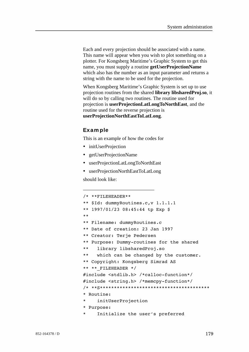
System administration
179852-164378 / D
Each and every projection should be associated with a name.This name will appear when you wish to plot something on aplotter. For Kongsberg Maritime’s Graphic System to get thisname, you must supply a routine getUserProjectionNamewhich also has the number as an input parameter and returns astring with the name to be used for the projection.When Kongsberg Maritime’s Graphic System is set up to useprojection routines from the shared library libsharedProj.so, itwill do so by calling two routines. The routine used forprojection is userProjectionLatLongToNorthEast, and theroutine used for the reverse projection isuserProjectionNorthEastToLatLong.
ExampleThis is an example of how the codes for• initUserProjection• getUserProjectionName• userProjectionLatLongToNorthEast• userProjectionNorthEastToLatLongshould look like:
/* **FILEHEADER**
** $Id: dummyRoutines.c,v 1.1.1.1
** 1997/01/23 08:45:44 tp Exp $
**
** Filename: dummyRoutines.c
** Date of creation: 23 Jan 1997
** Creator: Terje Pedersen
** Purpose: Dummy-routines for the shared
** library libsharedProj.so
** which can be changed by the customer.
** Copyright: Kongsberg Simrad AS
** **_FILEHEADER */
#include <stdlib.h> /*calloc-function*/
#include <string.h> /*memcpy-function*/
/* **S***************************************
* Routine:
* initUserProjection
* Purpose:
* Initialize the user’s preferred
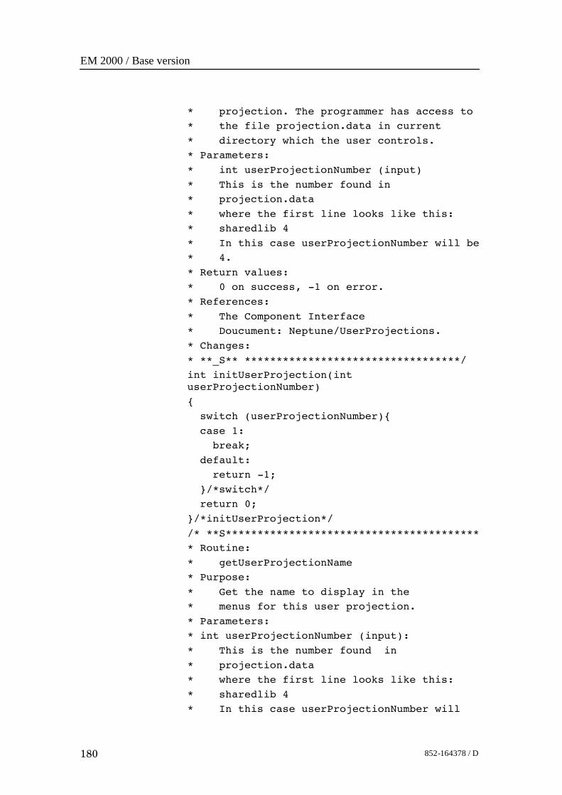
EM 2000 / Base version
180 852-164378 / D
* projection. The programmer has access to
* the file projection.data in current
* directory which the user controls.
* Parameters:
* int userProjectionNumber (input)
* This is the number found in
* projection.data
* where the first line looks like this:
* sharedlib 4
* In this case userProjectionNumber will be
* 4.
* Return values:
* 0 on success, -1 on error.
* References:
* The Component Interface
* Doucument: Neptune/UserProjections.
* Changes:
* **_S** **********************************/
int initUserProjection(intuserProjectionNumber)
{
switch (userProjectionNumber){
case 1:
break;
default:
return -1;
}/*switch*/
return 0;
}/*initUserProjection*/
/* **S****************************************
* Routine:
* getUserProjectionName
* Purpose:
* Get the name to display in the
* menus for this user projection.
* Parameters:
* int userProjectionNumber (input):
* This is the number found in
* projection.data
* where the first line looks like this:
* sharedlib 4
* In this case userProjectionNumber will
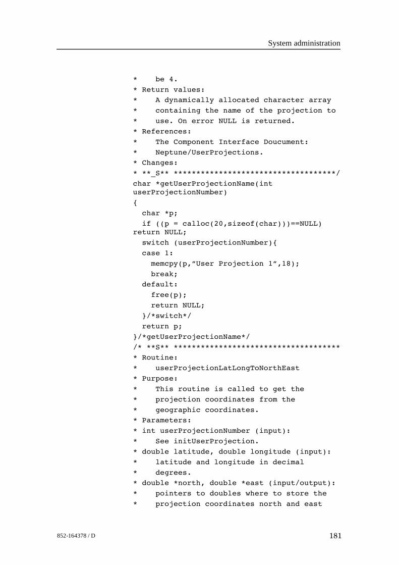
System administration
181852-164378 / D
* be 4.
* Return values:
* A dynamically allocated character array
* containing the name of the projection to
* use. On error NULL is returned.
* References:
* The Component Interface Doucument:
* Neptune/UserProjections.
* Changes:
* **_S** ************************************/
char *getUserProjectionName(intuserProjectionNumber)
{
char *p;
if ((p = calloc(20,sizeof(char)))==NULL)return NULL;
switch (userProjectionNumber){
case 1:
memcpy(p,”User Projection 1”,18);
break;
default:
free(p);
return NULL;
}/*switch*/
return p;
}/*getUserProjectionName*/
/* **S** *************************************
* Routine:
* userProjectionLatLongToNorthEast
* Purpose:
* This routine is called to get the
* projection coordinates from the
* geographic coordinates.
* Parameters:
* int userProjectionNumber (input):
* See initUserProjection.
* double latitude, double longitude (input):
* latitude and longitude in decimal
* degrees.
* double *north, double *east (input/output):
* pointers to doubles where to store the
* projection coordinates north and east
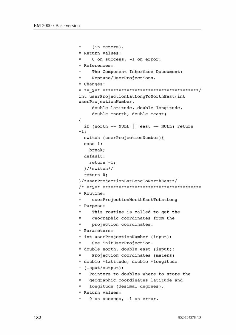
EM 2000 / Base version
182 852-164378 / D
* (in meters).
* Return values:
* 0 on success, -1 on error.
* References:
* The Component Interface Doucument:
* Neptune/UserProjections.
* Changes:
* **_S** ************************************/
int userProjectionLatLongToNorthEast(intuserProjectionNumber,
double latitude, double longitude,
double *north, double *east)
{
if (north == NULL || east == NULL) return-1;
switch (userProjectionNumber){
case 1:
break;
default:
return -1;
}/*switch*/
return 0;
}/*userProjectionLatLongToNorthEast*/
/* **S** *************************************
* Routine:
* userProjectionNorthEastToLatLong
* Purpose:
* This routine is called to get the
* geographic coordinates from the
* projection coordinates.
* Parameters:
* int userProjectionNumber (input):
* See initUserProjection.
* double north, double east (input):
* Projection coordinates (meters)
* double *latitude, double *longitude
* (input/output):
* Pointers to doubles where to store the
* geographic coordinates latitude and
* longitude (desimal degrees).
* Return values:
* 0 on success, -1 on error.
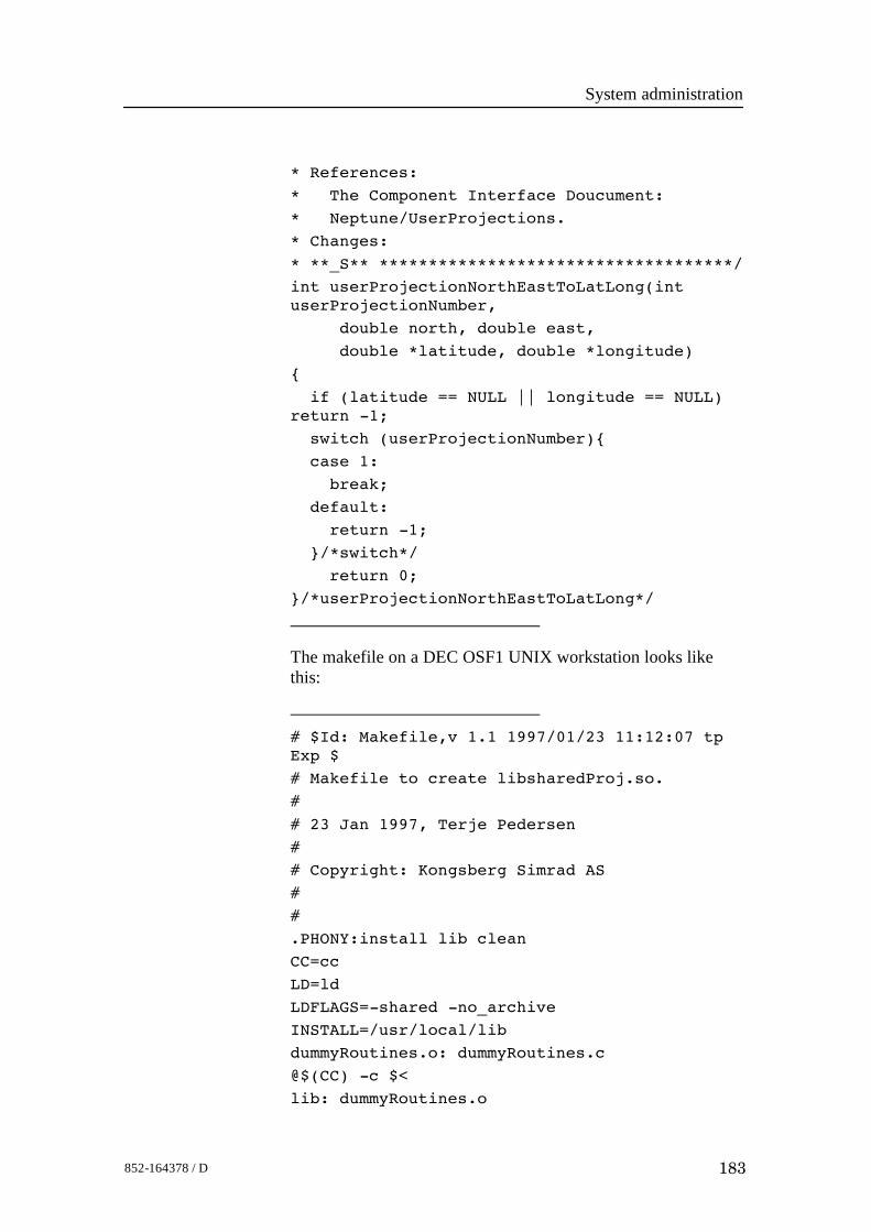
System administration
183852-164378 / D
* References:
* The Component Interface Doucument:
* Neptune/UserProjections.
* Changes:
* **_S** ************************************/
int userProjectionNorthEastToLatLong(intuserProjectionNumber,
double north, double east,
double *latitude, double *longitude)
{
if (latitude == NULL || longitude == NULL)return -1;
switch (userProjectionNumber){
case 1:
break;
default:
return -1;
}/*switch*/
return 0;
}/*userProjectionNorthEastToLatLong*/
The makefile on a DEC OSF1 UNIX workstation looks likethis:
# $Id: Makefile,v 1.1 1997/01/23 11:12:07 tpExp $
# Makefile to create libsharedProj.so.
#
# 23 Jan 1997, Terje Pedersen
#
# Copyright: Kongsberg Simrad AS
#
#
.PHONY:install lib clean
CC=cc
LD=ld
LDFLAGS=-shared -no_archive
INSTALL=/usr/local/lib
dummyRoutines.o: dummyRoutines.c
@$(CC) -c $<
lib: dummyRoutines.o
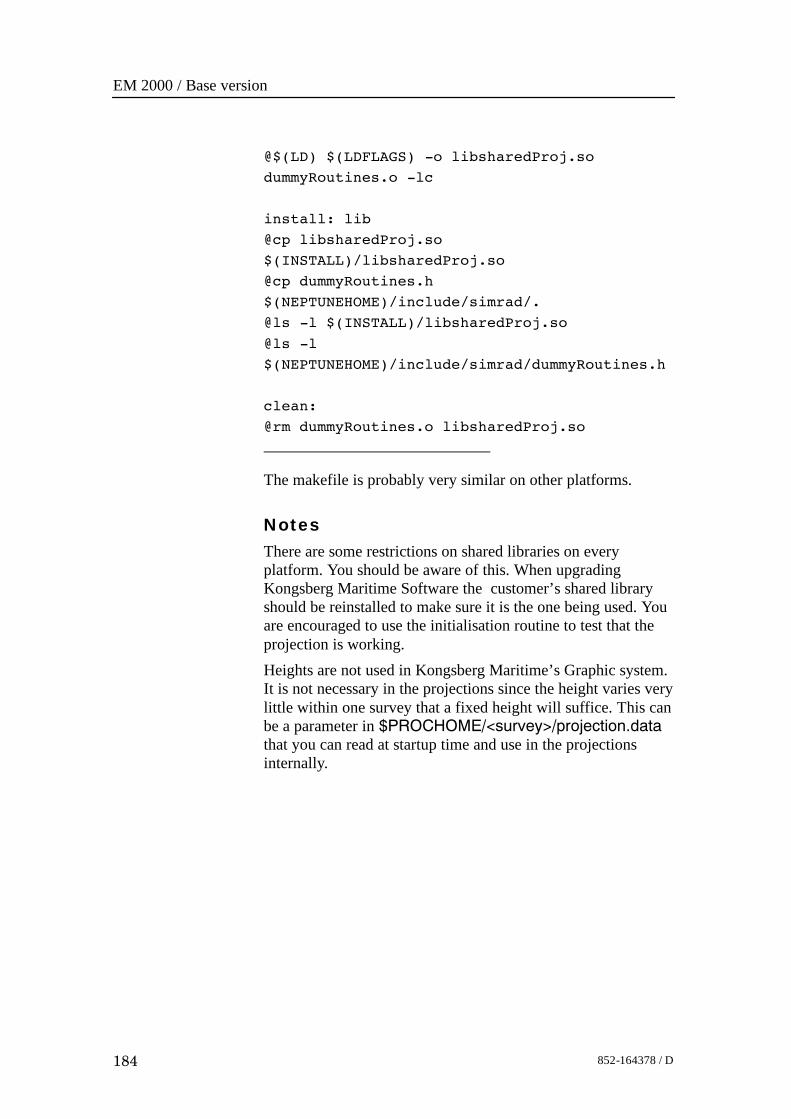
EM 2000 / Base version
184 852-164378 / D
@$(LD) $(LDFLAGS) -o libsharedProj.so
dummyRoutines.o -lc
install: lib
@cp libsharedProj.so
$(INSTALL)/libsharedProj.so
@cp dummyRoutines.h
$(NEPTUNEHOME)/include/simrad/.
@ls -l $(INSTALL)/libsharedProj.so
@ls -l
$(NEPTUNEHOME)/include/simrad/dummyRoutines.h
clean:
@rm dummyRoutines.o libsharedProj.so
The makefile is probably very similar on other platforms.
NotesThere are some restrictions on shared libraries on everyplatform. You should be aware of this. When upgradingKongsberg Maritime Software the customer’s shared libraryshould be reinstalled to make sure it is the one being used. Youare encouraged to use the initialisation routine to test that theprojection is working.Heights are not used in Kongsberg Maritime’s Graphic system.It is not necessary in the projections since the height varies verylittle within one survey that a fixed height will suffice. This canbe a parameter in $PROCHOME/<survey>/projection.datathat you can read at startup time and use in the projectionsinternally.
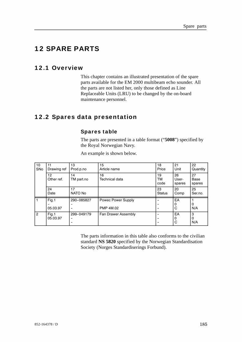
Spare parts
185852-164378 / D
12 SPARE PARTS
12.1 OverviewThis chapter contains an illustrated presentation of the spareparts available for the EM 2000 multibeam echo sounder. Allthe parts are not listed her, only those defined as LineReplaceable Units (LRU) to be changed by the on-boardmaintenance personnel.
12.2 Spares data presentation
Spares tableThe parts are presented in a table format (“5008”) specified bythe Royal Norwegian Navy.An example is shown below.
10SNo
11Drawing ref
13Prod.p.no
15Article name
18Price
21Unit
22Quantity
12Other ref.
14TM part.no
16Technical data
19TMcode
26User-spares
27Basespares
24Date
17NATO No
23Status
20Comp
25Ser.no.
1 Fig.1--05.03.97
290--085827----
Powec Power Supply
PMP 4M.02
------
EA0C
10N/A
2 Fig.105.03.97
299--049179----
Fan Drawer Assembly ------
EA0C
30N/A
The parts information in this table also conforms to the civilianstandard NS 5820 specified by the Norwegian StandardisationSociety (Norges Standardiserings Forbund).
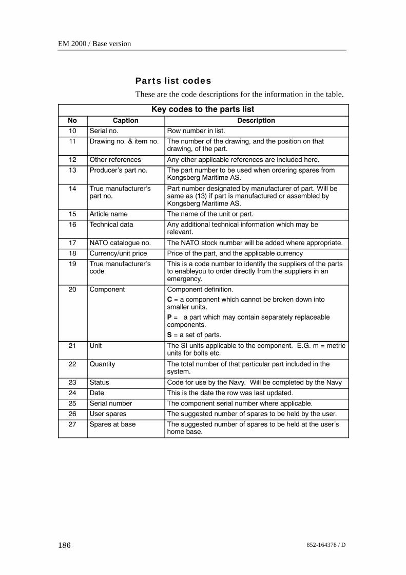
EM 2000 / Base version
186 852-164378 / D
Parts list codesThese are the code descriptions for the information in the table.
Key codes to the parts listNo Caption Description
10 Serial no. Row number in list.
11 Drawing no. & item no. The number of the drawing, and the position on thatdrawing, of the part.
12 Other references Any other applicable references are included here.
13 Producer’s part no. The part number to be used when ordering spares fromKongsberg Maritime AS.
14 True manufacturer’spart no.
Part number designated by manufacturer of part. Will besame as (13) if part is manufactured or assembled byKongsberg Maritime AS.
15 Article name The name of the unit or part.
16 Technical data Any additional technical information which may berelevant.
17 NATO catalogue no. The NATO stock number will be added where appropriate.
18 Currency/unit price Price of the part, and the applicable currency
19 True manufacturer’scode
This is a code number to identify the suppliers of the partsto enableyou to order directly from the suppliers in anemergency.
20 Component Component definition.
C = a component which cannot be broken down intosmaller units.
P = a part which may contain separately replaceablecomponents.
S = a set of parts.
21 Unit The SI units applicable to the component. E.G. m = metricunits for bolts etc.
22 Quantity The total number of that particular part included in thesystem.
23 Status Code for use by the Navy. Will be completed by the Navy
24 Date This is the date the row was last updated.
25 Serial number The component serial number where applicable.
26 User spares The suggested number of spares to be held by the user.
27 Spares at base The suggested number of spares to be held at the user’shome base.
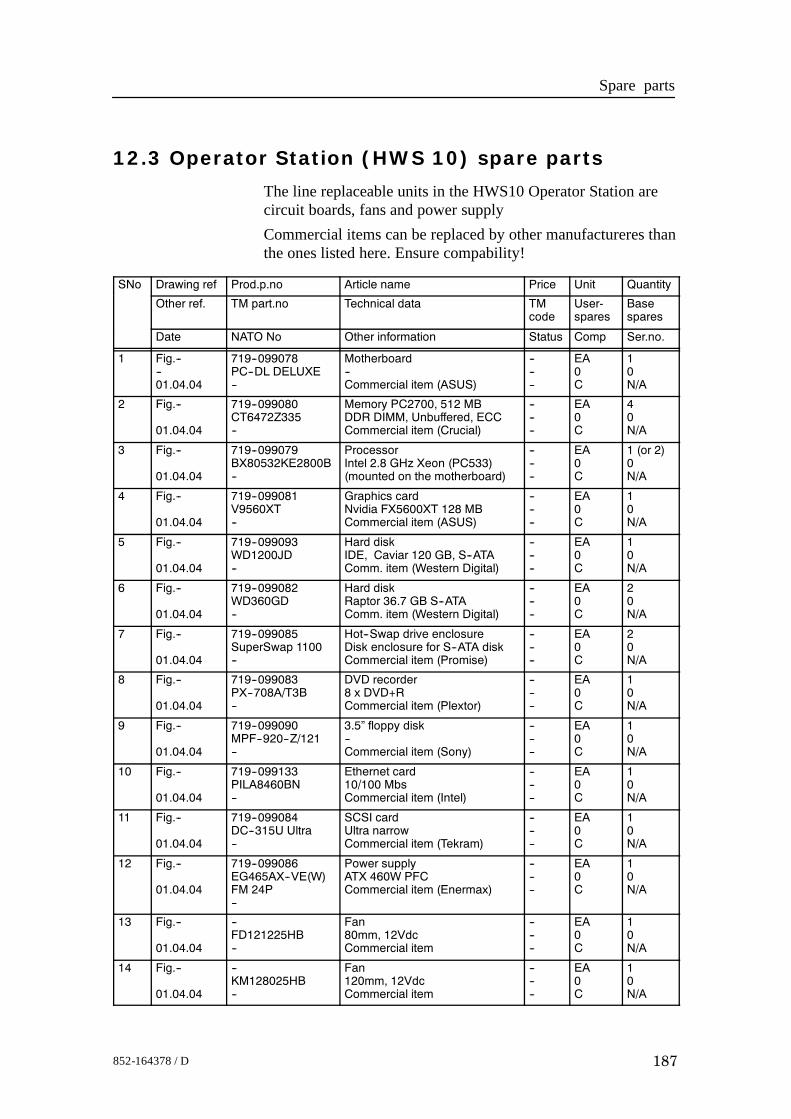
Spare parts
187852-164378 / D
12.3 Operator Station (HWS 10) spare parts
The line replaceable units in the HWS10 Operator Station arecircuit boards, fans and power supplyCommercial items can be replaced by other manufactureres thanthe ones listed here. Ensure compability!
SNo Drawing ref Prod.p.no Article name Price Unit Quantity
Other ref. TM part.no Technical data TMcode
User-spares
Basespares
Date NATO No Other information Status Comp Ser.no.
1 Fig.----01.04.04
719--099078PC--DL DELUXE--
Motherboard--Commercial item (ASUS)
------
EA0C
10N/A
2 Fig.--
01.04.04
719--099080CT6472Z335--
Memory PC2700, 512 MBDDR DIMM, Unbuffered, ECCCommercial item (Crucial)
------
EA0C
40N/A
3 Fig.--
01.04.04
719--099079BX80532KE2800B--
ProcessorIntel 2.8 GHz Xeon (PC533)(mounted on the motherboard)
------
EA0C
1 (or 2)0N/A
4 Fig.--
01.04.04
719--099081V9560XT--
Graphics cardNvidia FX5600XT 128 MBCommercial item (ASUS)
------
EA0C
10N/A
5 Fig.--
01.04.04
719--099093WD1200JD--
Hard diskIDE, Caviar 120 GB, S--ATAComm. item (Western Digital)
------
EA0C
10N/A
6 Fig.--
01.04.04
719--099082WD360GD--
Hard diskRaptor 36.7 GB S--ATAComm. item (Western Digital)
------
EA0C
20N/A
7 Fig.--
01.04.04
719--099085SuperSwap 1100--
Hot--Swap drive enclosureDisk enclosure for S--ATA diskCommercial item (Promise)
------
EA0C
20N/A
8 Fig.--
01.04.04
719--099083PX--708A/T3B--
DVD recorder8 x DVD+RCommercial item (Plextor)
------
EA0C
10N/A
9 Fig.--
01.04.04
719--099090MPF--920--Z/121--
3.5” floppy disk--Commercial item (Sony)
------
EA0C
10N/A
10 Fig.--
01.04.04
719--099133PILA8460BN--
Ethernet card10/100 MbsCommercial item (Intel)
------
EA0C
10N/A
11 Fig.--
01.04.04
719--099084DC--315U Ultra--
SCSI cardUltra narrowCommercial item (Tekram)
------
EA0C
10N/A
12 Fig.--
01.04.04
719--099086EG465AX--VE(W)FM 24P--
Power supplyATX 460W PFCCommercial item (Enermax)
------
EA0C
10N/A
13 Fig.--
01.04.04
--FD121225HB--
Fan80mm, 12VdcCommercial item
------
EA0C
10N/A
14 Fig.--
01.04.04
--KM128025HB--
Fan120mm, 12VdcCommercial item
------
EA0C
10N/A
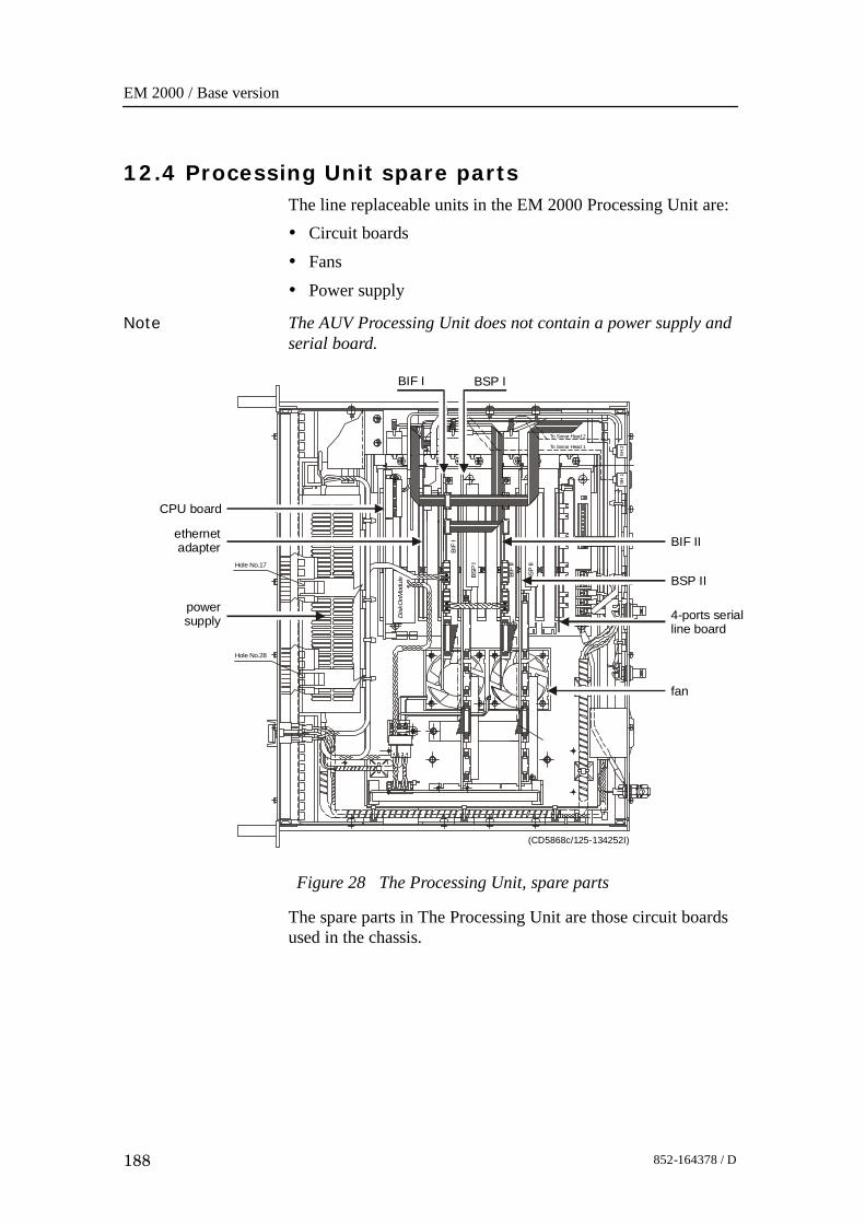
EM 2000 / Base version
188 852-164378 / D
12.4 Processing Unit spare partsThe line replaceable units in the EM 2000 Processing Unit are:• Circuit boards• Fans• Power supply
Note The AUV Processing Unit does not contain a power supply andserial board.
Figure 28 The Processing Unit, spare parts
Hole No.17
Hole No.28
Dis
kOnM
odul
e
BIF
I
BIF
II
BSP
I
BSP
II
To Sonar Head 1
To Sonar Head 2
SH 2
SH 1
(CD5868c/125-134252I)
CPU board
power supply
ethernet adapter
BIF I
BSP II
BSP I
BIF II
4-ports serial line board
fan
The spare parts in The Processing Unit are those circuit boardsused in the chassis.
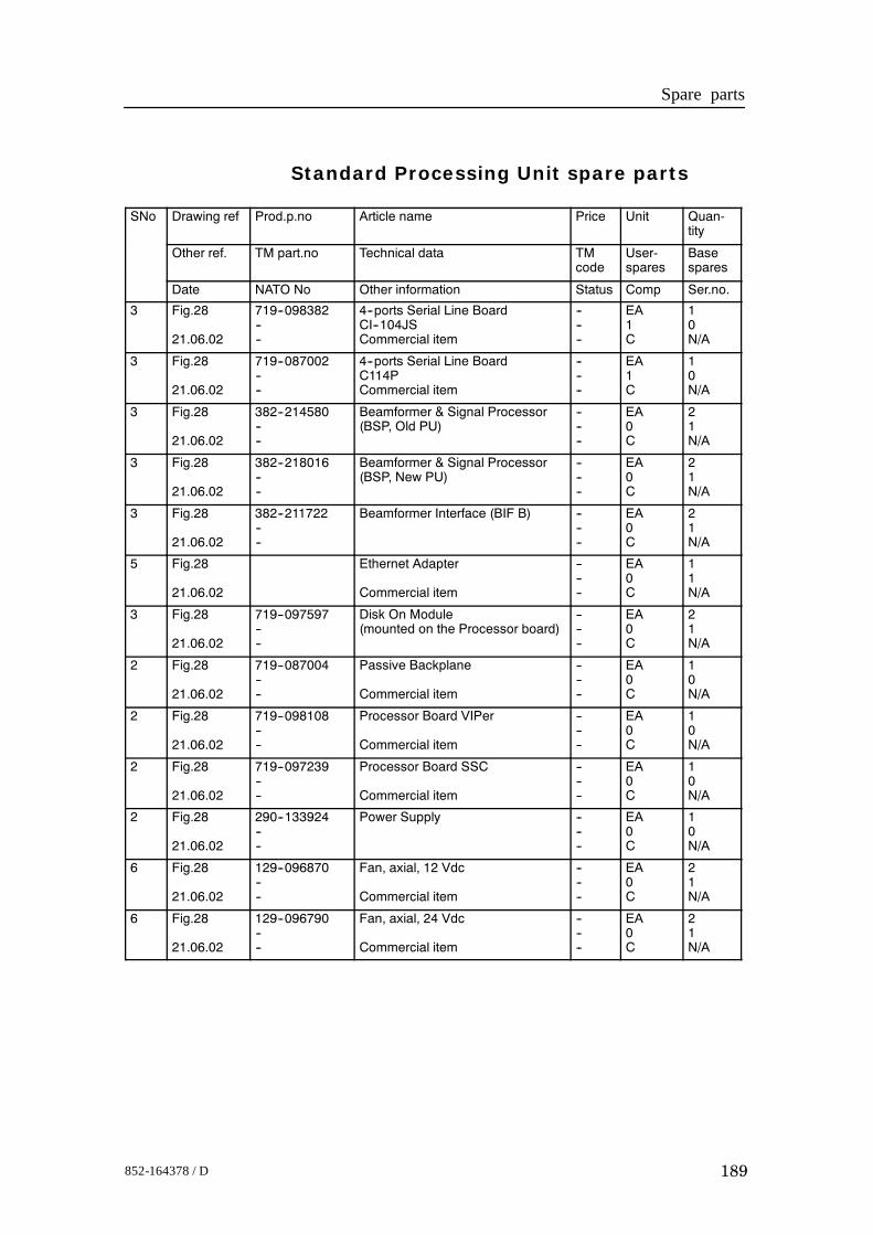
Spare parts
189852-164378 / D
Standard Processing Unit spare parts
SNo Drawing ref Prod.p.no Article name Price Unit Quan-tity
Other ref. TM part.no Technical data TMcode
User-spares
Basespares
Date NATO No Other information Status Comp Ser.no.
3 Fig.28
21.06.02
719--098382----
4--ports Serial Line BoardCI--104JSCommercial item
------
EA1C
10N/A
3 Fig.28
21.06.02
719--087002----
4--ports Serial Line BoardC114PCommercial item
------
EA1C
10N/A
3 Fig.28
21.06.02
382--214580----
Beamformer & Signal Processor(BSP, Old PU)
------
EA0C
21N/A
3 Fig.28
21.06.02
382--218016----
Beamformer & Signal Processor(BSP, New PU)
------
EA0C
21N/A
3 Fig.28
21.06.02
382--211722----
Beamformer Interface (BIF B) ------
EA0C
21N/A
5 Fig.28
21.06.02
Ethernet Adapter
Commercial item
------
EA0C
11N/A
3 Fig.28
21.06.02
719--097597----
Disk On Module(mounted on the Processor board)
------
EA0C
21N/A
2 Fig.28
21.06.02
719--087004----
Passive Backplane
Commercial item
------
EA0C
10N/A
2 Fig.28
21.06.02
719--098108----
Processor Board VIPer
Commercial item
------
EA0C
10N/A
2 Fig.28
21.06.02
719--097239----
Processor Board SSC
Commercial item
------
EA0C
10N/A
2 Fig.28
21.06.02
290--133924----
Power Supply ------
EA0C
10N/A
6 Fig.28
21.06.02
129--096870----
Fan, axial, 12 Vdc
Commercial item
------
EA0C
21N/A
6 Fig.28
21.06.02
129--096790----
Fan, axial, 24 Vdc
Commercial item
------
EA0C
21N/A
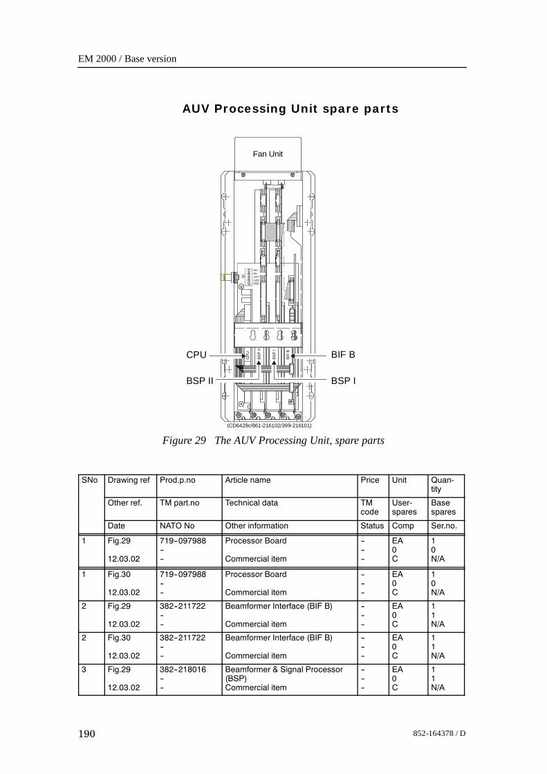
EM 2000 / Base version
190 852-164378 / D
AUV Processing Unit spare parts
Figure 29 The AUV Processing Unit, spare parts
CPU
BSP
II
BSP
I
BIF
B
Fan Unit
+5V
J5 -5V-12V+12VGND
CPU
BSP IBSP II
BIF B
(CD6429c/861-216102/399-216101)
SNo Drawing ref Prod.p.no Article name Price Unit Quan-tity
Other ref. TM part.no Technical data TMcode
User-spares
Basespares
Date NATO No Other information Status Comp Ser.no.
1 Fig.29
12.03.02
719--097988----
Processor Board
Commercial item
------
EA0C
10N/A
1 Fig.30
12.03.02
719--097988----
Processor Board
Commercial item
------
EA0C
10N/A
2 Fig.29
12.03.02
382--211722----
Beamformer Interface (BIF B)
Commercial item
------
EA0C
11N/A
2 Fig.30
12.03.02
382--211722----
Beamformer Interface (BIF B)
Commercial item
------
EA0C
11N/A
3 Fig.29
12.03.02
382--218016----
Beamformer & Signal Processor(BSP)Commercial item
------
EA0C
11N/A

Spare parts
191852-164378 / D
Figure 30 The AUV Processing Unit, spare parts
CPU
BSP
I
BIF
B
Fan Unit
+5V
J5 -5V-12V+12VGND
CPU
BSP I
BIF B
(Cd6429d/860-218015aa)
3 Fig.30
12.03.02
382--218016----
Beamformer & Signal Processor(BSP)Commercial item
------
EA0C
11N/A
4 Fig.29
12.03.02
382--215857----
Passive Backplane ------
EA0C
10N/A
4 Fig.30
12.03.02
382--215857----
Passive Backplane ------
EA0C
10N/A
5 Fig.29
12.03.02
719--097987----
Disk On Module(mounted on the Processor board)
------
EA0C
1N/A
5 Fig.30
12.03.02
719--097987----
Disk On Module(mounted on the Processor board)
------
EA0C
1N/A
6 Fig.29
21.06.02
129--098158----
Fan, axial, 5 Vdc
Commercial item
------
EA0C
1N/A
6 Fig.30
21.06.02
129--098158----
Fan, axial, 5 Vdc
Commercial item
------
EA0C
1N/A
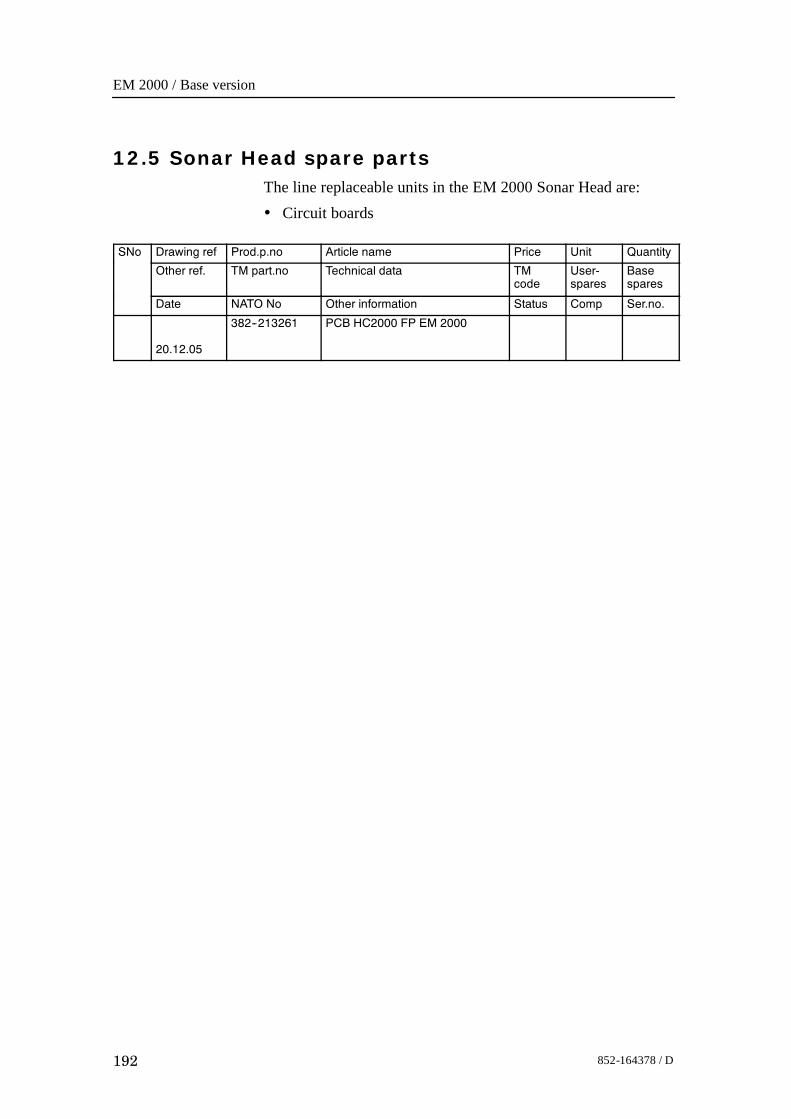
EM 2000 / Base version
192 852-164378 / D
12.5 Sonar Head spare partsThe line replaceable units in the EM 2000 Sonar Head are:• Circuit boards
SNo Drawing ref Prod.p.no Article name Price Unit Quantity
Other ref. TM part.no Technical data TMcode
User-spares
Basespares
Date NATO No Other information Status Comp Ser.no.
20.12.05
382--213261 PCB HC2000 FP EM 2000

Maintenance manual
193852-164378 / D

Maintenance manual
1852-164378 / D
E 2006 Kongsberg Maritime

EM2000
Maintenance
manual/Baseversion
EM2000
Maintenance
manual/Baseversion
EM2000
Maintenance
manual/Baseversion
EM2000
Maintenance
manual/Baseversion