km c554e-20150703094712 - universidade do minho wall is 10 ft high and its cross-section consists of...
TRANSCRIPT

1049
ESTlMATION OF TEMPERATURE ANO CREEP STRESSES IN COMPOSITE MASONRY WALLS
SUBHASH C. ANAND and AYUBUR M. RAHMAN Department of Civil Engineering
Clemson University Clemson, South Carolina, 29634-0911, USA
ABSTRACT
The results of a computational procedure based on the principal of superposition to estimate creep strains in composite masonry walls are presented in this paper. Stresses in the collar joints of composite walls due to differential temperatures on the inside and outside wythe faces are also presented. It is shown that although substantial additional strains occur due to creep and temperature changes, their effect on the corresponding stresses is minimal in a composite wall.
INTRODUCTION
Composite action in a masonry wall is obtained when the two independent wythes are connected together by metal ties and the cavity between the two wythes is grouted as shown in Fig. 1. As reported in the literature [6, 7,9), strains and stresses in masonry due to temperature variations may not be insignificant. In composite ma~onry walls, in particular, the effects of temperature variations may even be more important. In addition, if only the interior block wythe is subjected to externaI loads, these are transferred partially to the exterior brick wythe, thus causing stresses and strains in the wythes and collar joint. These different sustained stresses tend to produce different creep strains, thereby, producing additional shear stresses in the collar joint. This process of stress redistribution continues for a substantial period of time until most of the creep deformation has taken place. As in the case of temperature strains, creep strains could substantially alter the stress condition in a composite wall.
It is therefore, important that the effects of temperature and creep strains be included in the analysis and design of composite masonry walls. In this paper, a two dimensional finite element model for plane strain condition is utilized to study the above mentioned effects. Theory and development necessary to determine equivalent nodal loads for thermal and creep strains as well as the details of the computational technique have previously been presented by the authors elsewhere [3). Analyses are presented to show the significance of temperature and creep strains on stress redistribution in composite masonry walls.

Briek Wyfhe Collor Joinf
Fig. 1 Composite Masonry Wall
120
'iõ -'" 100 .... ., 2 c 80 .~
êii 60
Q. O> ., U 40
~ '2 20 Q.
Cf)
O
1050
Block Mosonry
40 80 120 160 200 240 280 320 360
Time (Days)
Fig. 3 Creep Curves f o r Brick and Block Masonry
o (\J
p= 0.21 ksi
" . k I- ' 11 '1' 4 Bne a" Bloek --Y L2 "collor Joinf
Fig. 2 Finit e Element Mesh
T 2 T(x)=(-;--il 6TTT2
!;:j ITI
1 -x T
!;:j
Tlr I~
Bloek F'::·;::: ('.i;: .• ' Briek
::::~<~::.:: i .., w - I
Fig. 4 Temperature Profile Across Wall Thickness
•
-

--
1051
EXAMPLE PROBLEM
In order to estimate the effects of creep as welL as thermal strains on stresses and strains in the collar joint, a long composite waLl shown in Fig. 2 is analyzed. The wall is 10 ft high and its cross-section consists of an 8 in concrete block wythe that is connected to a 4 in brick wythe through a 2 in thick grouted collar joint. It is assumed that the dead weight Df the slab and live loads act only on the concrete block wythe at the top. It is further assumed that the diaphragm action of the floor slab provides a lateral support at the top of the wall.
It is known from working with the previous models [1-3] that most of the load transfer from the loaded wythe to the unloaded wythe occurs near the top. Consequently, a relatively fine finite element mesh is provided near the top Df the wall as shown in Fig. 2. The total number of quadrilateral elements and nodal points used in the analysis are 350 and 290, respectively. The block wythe is subjected to a load of 20 kips per foot that le~ds to uniform pressure of 0.21 ksi which i5 equal to 20% of the concrete block strength measured in the laboratory. This is the maximum permissible load on masonry as prescribed by BIA [11]. The material properties for various constituents Df the composite wall are computed as a prescribed in Ref. [11] and are based on their laboratory compressive strengths. The values for the elastic moduli and Poisson's ratios for the block wythe, brick wythe and grouted collar joint are calculated as 1,040 ksi, 2,000 ksi and 1,600 ksi, and 0.25, 0.25 and 0.20, respectively.
Creep Analysis The creep behavior of the individual wythes has been taken from the available literature [7,91, 10] and is shown in Fig. 3. In addition, the creep behavior of the grouted collar joint i5 a5sumed to follow that Df the concrete block wythe. Numerical values corresponding to the creep curves shown in Fig. 3 where provided as data at every 10 day interval in the computer programo As the wall is very long, it is in a state of plane strain and thus only a unit length of the cross section can be analyzed.
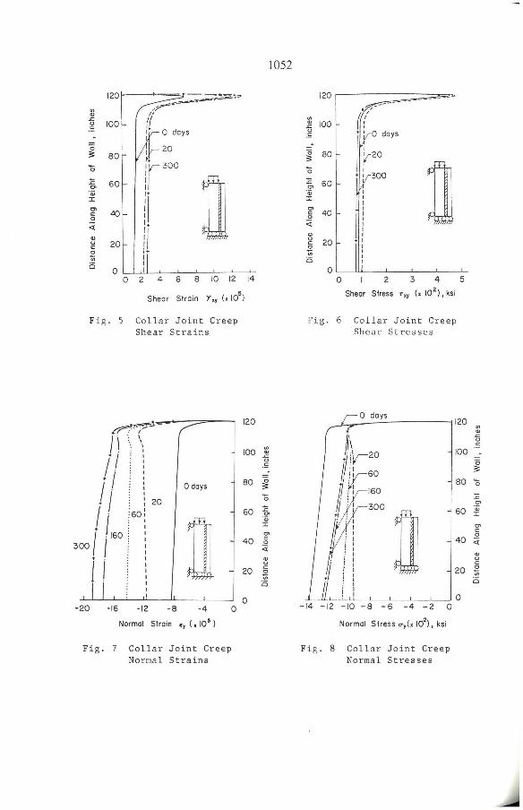
The wall is initially analyzed for the instantaneously applied loads, after which the effect of creep in the wall due to the sustained loads is examined for up to 300 days at which time most of the creep should have occurred as is obvious from figo 3. Starting from zero days, this total time is discretized into 10 intervals of five days each, seven intervals of 10 days each, and nine intervals of 20 days each to yield a total of 26 time steps to obtain the complete solution. Some typical results for stresses and strains in the collar joint adjacent to the block wythe are plotted in Figs. 5 through 8, in which the results for the elastic analysis are labeled as zero days, whereas those for the creep analysis are indicated by the respective number of days after the load application.
figure 5 shows the shear strain in the collar join. As materiaIs creep with time, the shear strain in the collar joint also increases and its magnitude at 300 days is approximately twice as much as at the time of load application. The rate of strain increase is larger in the beginning and slows down appreciably with time. However, the shape of shear strain diagram remains essentially the same. As far as the shear stress variations are concerned, Fig. 6 shows no substantial changes due to creep. A slight increase in stress during the early period of creep and its
1052
120~---;~~~ ~"f'''''''''
'" ,r~
'" /-.<::
100 r( " c .- ~ O days o I I 20 ;;: 80 • - ir 300 o
:c
ru OI 60
'Qj
li I
OI c 40 o
I. <{
I1 '" " 20 c o I.
'" I
i5 I
o o 2 4 6 8 10 12 14
Shear Strain Y,y (,105
)
Fig. 5 Collar Joint Creep Shear Strains
+~7j.--
/I ~: \ . I I· . I I . o days
i I : : 20
300 i 1',," I . . I n
-20 -16 -12 -8 -4 o Normal Strain " (, 10' )
Fig. 7 Collar Joint Creep Normal Strains
120
100 11 " .S
80 ~ õ
60 t "o; I
OI
40 g <t
'" " 20 g -:;; i5
o
120
'" ~ 100 " I iI V- 0 days .S
Õ ;;: 80
õ I r
n :c • I 300 OI
"r 'Qj I
'" 40 c o <t
'" " 20 c
~ i5
o O 2 3 4 5
Shear Stress t',y (x 102). ksi
Fig . 6 Collar Joint Creep Shear Stresses
I o days 1120
'" '" .<::
h tliV-20
11 :1
1!y-60
!t160
tf4!; 300
} ! I
+ i: : I i I • I
j ! : I : I
~
100 " .S
~ 80 Õ
:c OI
60 ª OI C o
40 <t
'" " c 20 E
.'!! o
I Il, : I -14 -12 ~IO -8 _ I I lO 6 -4 -2 O
Normal Stress CTy(X 102). ksi
Fig. 8 Collar Joint Creep Normal Stresses

1053
eventual deerease during the later time period is due to the different ereep behavior of the eonerete bloek and briek wythes as shown in Fig. 3.
Normal vertical strains in the eollar joint are shown in Fig. 7. With time, these normal strains inerease due to creep and beeome approximately twiee their elastie values. The normal stresses in the eollar joint, on the other hand, are similar to the normal strains only at the time of the instantaneous load applieation [Fig. 8]. Due to the different ereep displacements in the wythes at different times, the normal stresses in the collar joint deerease by approximately 30% during the first 20 days; however, most of this stress decrease is regained during the next 280 days. The final normal stresses are slightly smaller than those at time t = O, indicating that there is some stress relief in the eollar joint due to ereep. This is also substantiated in Fig. 6 where the shea r stress in the eollar joint at 300 days is smaller than that at zero days.
Analysis due to Thermal Strains A wide range of vaIues for the coeffieient of thermal expansion of bloek, grout and briek is quoted in the literature [5-7]. Based upon this information, coeffieients of thermal expansion for the bIoek and briek masonry, and grout have been ehosen as 5.0xlO- 6 in./in.-deg.F, 3.2xlO- 6 in./in.-deg.F, and 6.0xlO- 6 in./in-deg.F, respeetively, in this st udy
The temperatures at the inner face of the bloek wythe and outer face of the briek wythe of a wall may be taken as the room tempe rature and outside ambient temperature, respeetively. To find the temperature at any point within the wall, one needs a temperature profile aeross the eross seetion thr ou gh the three different materiaIs, namely, eonerete bloek, grout and eIay briek. Literature gives very littIe information about the above men ti oned temperature profile. On the basis of heat flow anaIysis under steady state eonditions for interseeting walls, Rahman and Suter [8] used a parabolie temperature profile across the masonry wall interseetion. Based upon their researeh, a parabolie temperature profile, as shown in Fig. 4, has been assumed aeross the thiekness of the wall in this study. This temperature profile may be expressed as
where I TIl > I T21 , w is the wall thiekness wall interior where temperature = TI' parabolie temperature profile may be given
(1)
and x is the distanee from the SimiIarly, if I T21 > I TIl, the by
Using the above temperature profiles, the temperatures at various points aeross of the wall thiekness can be obtained for different eombinations of interior and exterior temperatures.
It is assumed in the analysis thatthe stress-free temperature at the time of eonstruetion of the composite wall is 60°F. Three different sets of inside-outside temperatures are eonsidered. These are 80°F, 80°F for a unifo rm temperature inerease of both wythes, 80°f, 110°F for a 30 degree higher temperature on the outside than inside, and 70°F, -10°F representing a heated inside environment on a eold winter day. The temperatures at the eentroids of various elements across the width of the

1054
wall are obtained by using one of the appropriate Eqs. or 2. Subtraction of the stress-free temperature of 60"F from the element temperatures yields the temperature changes which are utilized in the thermal analysis.
The resulting shear strains and shear stresses in the collar joint due to the three temperature combinations are shown in Figs. 9 through 12 in which the corresponding values are also plotted for the externai loads. It is evident from Fig. 9 that the shear strain distribution due to externaI loads is different than that due to the temperature changes. This is quite obvious as the externaI loads are applied only on the block wythe whereas the temperature changes lead to equivalent loads that are applied on both wythes in the horizontal and vertical directions . It can also be noted that the shear strains in the collar joint due to temperature changes can be either positive or negative depending upon the temperature increase or decrease in the two wythes. The collar joint shear stress distributions are shown in Figs. Ii and 12.
One can see in Fig. li that the largest value of shear stress due to the temperature change alone is equal to -20 psi which occurs at the top of the wall for a temperature combination of 70"F,-10"F. The maximum shear stress in the collar joint due to the externai Ioads aIone, on the other hand, is equal to 46 psi and it occurs at approximately 2 in from the top of the wall. The maximum shear stress due to the combined eEfects of the externaI loads and temperature changes occurs for a temperature combination of 80"F, 100"F at about 2 in from the top and has a value of 50 psi. This indicates that the increase in shear stress in the collar joint due to the specified temperature changes is only 4 psi which is approximately 8% of the stress due to the externai loads.
The normal vertical strain in the collar joint due to the externai loads and temperature changes are shown in Figs. 13 and 14. It is seen that the vertical strains are compressive due to the externai loads as well as due to 70"F,-10"F temperature combination. The temperature strains are of the order of one to two times larger than those due to the externai loads.
The normal stresses in the collar joint due to the externai loads and temperature changes are plotted in Figs. 15 and 16. The normal stress is zero at the top of the wall both due to the externai loads and thermal strains. As the load transfer occurs from the loaded wythe to the unloaded wythe in the top 5 to 6 in length of the wall, the normal stress in the collar joint becomes uniform from this height downwards. The maximum normal stress due to the externai loads is equal to 150 psi compressive. Due to an increase in temperature combination to 80"F,110"F, the total compressive stress in the collar joint increases to 270 psi whereas a temperature combination of 70"F,-10"F together with the externai loads produces a tensile stress in the collar joint of approximately 135 psi.
The grout in the collar joint is a tension-weak material and, thus, it should be of interest to compute the maximum tension in the collar joint by considering the action of only the dead loads and temperature ehanges. It is estimated that half of the externai loads always aet as dead loads, and yield a eompressive stress in the eollar joint of 75 psi. Combining this with a temperature eombination of 70"F,-10"F, which produces a tensile stress of 285 psi due to the temperature change alone,

Individual Effect
(Externai Laad ar Temp.)
120 r '"
.r. I OI I '
~ , <> 100 I .5 I ! ti I Ambient 60~60OF ~ 80
I Externai Laad - I o I 80~80°F E I o> 60 I 70~ -10°F '0; J: I o> I 80~IIOOF c::
I n o 40 ti I OI <> c:: o 20 ... i5
O -2 O 2 4 6
Shear Stroin r" (xIO')
Fig. 9 Collar Joint Shear Strains due to Loads or Temperature
120
'" .fi 100 ,5
-o
'" c: o o OI <> c: 2 '" i5
80
60
40
20
Individual Effect
(Externai Load ar Temp,)
- --~-=~/""-----=::>
Ambient 60~60OF
Externai Laad
80~ 80°F
70~ -10°F
ao, "O" n 0_2 4
Shear Stress T" (xI0 2), ksi
Fig. 11 Collar Joint Shear Stresses due to Loads or Temperature
1055
Cambined Eftect (Externai Laod ar Temp.)
- - gOT----=::=::::====',=
:(l100 ~ <> ,5
o 80 60~ 60°F
~ 80~ 80°F -o
1: o> 60 'o; J: o> c::
n o o 40 .. <> c:: o ~
20 Cl
o o 4 6
Sheor Stroin Y (xIO') "
Fig. 10 Collar Joint Shear Strains due to Loads and Temperature
Combined E ffect (Externai Lood ond Temp,)
8
- - -,20i----====::::::::;::::;;;::O'::> /~
'" ( .. 100 ~ ( u ,5 I 60°,60OF
o ~ 80 I 800,80OF
- I o 700,-100 F :i:: I o>
60 'o; I :I:
o> c: I
D o o 40 .. I <> c: I o ... i5 20 I
I O
-2 -I O 2 3 4
Shear Stress T,,(XIO'), ksi
Fig. 12 Collar Joint Shear Stresses due to Loads
and Temperature
5

.. cu
.<:
" .S
c ~
Õ
1: '" '<;
::t:
g' .9 c cu " c ~ .. o
.. cu
.<:
" .S
Õ ~
Õ 1:' '" '<; ::t: co c o õ cu u § .!!! c
Individual Effecl
(Exlernal Load or Temp.)
120 ;- -" ,
\ I 1
100 I 1
1
n\ I 80
I 60 ~ . o
I ." <D c . .3 o
40 I <D ~.
i~_ õ .. bl E 'E o ·
cu <Xl ' cu 15 . -' 20 [~ ;; E o: ' 0
w « <Xl . 1<Xl o r--I
O -40 -30 -20 -10 O 10 20
Normal Slrain " (x lO')
Fi g . 13 eollar Joint Normal Stra i ns due t o Loads or Temperature
120
100
80
60
40
20
Individual Effecl (Externai Load or Temp.)
. !f ; ----- .......
I I .. .
O
.....
<D
~I .-
D O <D
o i~ :It. ,. c 'O ;co cu
. .. :0 " :c I~ g E
" «
1
-10 O 10 20
Normal Slress (/", (X 102 ), ksi
\ \ \ \ I I I I \ I I I I I~ \2 I '_ lo Ir--I \ I 30
F ig . 15 e ollar Jo i nt Normal Stre sses due to Loads or Temperature
1056
120
.. cu
~ 100
õ ~
80 õ 1: .~ 60 ::t:
co
Combined Ettecl
(Exlernal Load and Temp.)
,.. / \
i \ I I
i I I I I I I I : l .. 1 ...
~
::- 1 ;~I~ ·0
n ~ 40 !?I <D :00 ·6 : <Xl I <Xl
cu ·01 <D " ""1 c
o I
I -:;;
20 o I I
O L-.J. -40 -20 O 20
, (x 105 ) Normal Slram "
F i g . 14 eollar Joint Normal Strains due t o Loads a nd Tempera ture
120 ,-
.. .fi 100 .S
~ 80 Õ
1: co '<; 60
Combined Ettecl (Exlernal Load and Temp.)
,...-' ..... . ~.
'" ! :' '\
I , I
i I I
I I I
i I 1
i I ::t: b'n I ... .. Ot I&. o . . § Q . o : O -I õ 40 =1 <Xl, <D
~I , 4J o o: "ô ~ <XlI <Xl:
<D ,...,
o 20 . I 1 I
O~ - 30 -20 -10 O 10 20
Normal Slress (/", (x 102), ksi
Fi g. 16 eollar Jo i nt Normal Stresses due to Loads and Temp e rature

1057
leads to a maximum tensile stress in the collar joint of 210 psi gecause of the combined effects of the dead loads and temperature changes. The average laboratory compressive strength of the grout used in the test specimens was 2,625 psi. Therefore, the maximum tensile stress of grout at failure can be assumed as 260 psi, which is larger than the maximum tensile stress in the collar joint computed above.
CONCLUSIONS
The results of the analysis indicate that alI strains do increase substantial ly due to creep during the first 300 days, most of the se during the first mon th after the load application. On the other hand, the shear »tresses in the collar joint remain almost constant with time. Normal stresses in the collar joint reduce between 10% and 30%. The magnitude of the maximum shear stress in the collar joint due to the assumed externa1 loads and creep is approximately 50 psi which is less than the max~num average shear stress of 60 psi observed at failure in the laboratory te» ts.
The shea, stresses and strains in the collar joint do not undergo any subs tantial changes due to the realistic temperature variations assumed in the analysis. Particularly, th e maximum value of the collar joint shear stress changes ooly from 46 to 50 psi, which is we1l within the fai lure range. The normal stresses in the collar joint, on the other hand, can change from a compressive value of 150 psi for the external loads alone to a tensile value of 210 psi for the dead loads and assumed temperature changes . Although, this stress is smaller than the tensile fai1ure limit stress of the grouted collar joint, the value is quite large to give the desired factor of safety against a tension failure. Accordingly, vertical tension steel must be provided in the collar joint to inhibit a tension failure.
One additiona l comment which must be made here concerns the shear stress distribution in the collar joint. It can be seen in Fig. 12 that the maximum value of shear stress, which occurs near the very top, is equal to 50 psi whereas the average value in the major portion of the wall is only 12 psi. The average fai1ure shear stress in the collar joint obtained experimentally, on the other hand, is approximately 60 psi, however, its distribution is unknown. tt is impossible, therefore, to predict a factor of safety against shear failure unless detailed shear stress distributions within the collar joint can be estimated fram the measured strains. Efforts are currently underway at Clemson University to do just that.
ACKNOWLEDGMENTS
The research reported in this paper was supported by Grant No. ECE-8410081 from the National Science Foundation. Computations were carried out on a VAX-11/780 at the Computational Laboratory of the College of Engineering at Clemson University. The financiaI support of NSF and the cooperation of the Col1ege of Engineering are gratefully acknowledged.
1058
REFERENCES
1. Anand, S.C. Dandawate, E., and Brown, R.H., "A Finite Element Model for Creep in Composite Masonry," Department of Civil Engineering Clemson University, Clemson, S.C. Report No. 20S-84, 1984.
2. Anand, S.C., and Rahman, M.A., "Creep Modelling for Masonry Under Plane Strain," Proceeding, Ninth Conference on Electronic Computation, University of Alabama at Birmingham, Alabama, February 23-26, 1986, pp. 629-643.
3. Anand, S.C., and Rahman, A.M., "Temperature and Creep Stresses in Composite Masonry Walls," in 'Advances in Analysis of Structural Masonry,' proceedings, ASCE, Structures Congress, ed. S.C. Anand, New Orleans, LA, Sept. 15-18, 1986, pp. 111-132.
4. Bazant, Z.P. , "Mathematical Models for Creep and Shrinkage of Concrete," in Creep and Shrinkage of Concrete Structures, ed., Bazant, Z.P., and Wittman, F.H., John Wiley and Sons, 1982, pp. 312-315.
5. Grimm, C.T., "Thermal Strain in Brick Masonry," proceedings of the Second North American Masonry Conference, University of Maryland, College Park, Maryland, August 9-11,1982, pp. 34.1-34.21.
6. Grimm, C.T. and Fowler, D.W., "Differential Movement in Composite Load-Bearing Masonry Walls," Journal of the Structural Division, ASCE, VoI. 105, No. ST7, July 1979, pp. 1277-1288.
7. Lenczner, D., and Salahuddin T., "Creep and Moisture Movements in Masonry Piers and Walls," Proceedings, 1st Canadian Masonry Symposium, University of Calgary, Calgary, 1976, pp. 72-86.
8. Rahman, A.H., and Suter, G.T., "Thermal Stresses in Intersecting Masonry Walls," proceedings, Third North American Masonry Conference, University of Texas at Arlington, Texas, June 1985, pp. 37.1-37.14.
9. Shrive, N.G., and England, G.L., "Elastic, Creep and Shrinkage Behavior of Masonry," International Journal of Masonry Construction, VoI. 1, No. 3, 1981, pp. 103-109.
10. Warren, D., Distribution Second North College Park,
and Lenczner, D., "Measurement of the Creep Strain in an Axia1ly Loaded Brickwork Wall," proceedings, American Masonry Conference, University of Maryland,
MD, August 9-11, 1982, pp. 5.1-5.19.
11. "Rec omme nded Prac t ice for Enginee red Brick Masonry," Brick Ins t i tute of America, McLean, VA, 1975.