klima floorheating mat+cable 2009 final · installation instructions k l i m a electric underfloor...
TRANSCRIPT
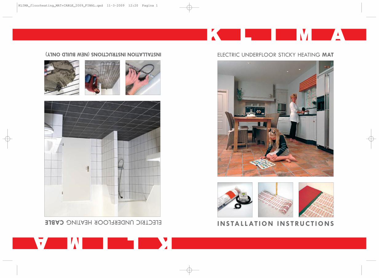
INSTALLAT ION INSTRUCT IONS
KK LL II MM AAELECTRIC UNDERFLOOR STICKY HEATING MAT
KKLLIIMMAA
INSTALLATION INSTRUCTIONS (NEW BUILD ONLY)
ELECTRIC UNDERFLOOR HEATING CABLE
KLIMA_floorheating_MAT+CABLE_2009_FINAL.qxd 11-3-2009 12:20 Pagina 1

2
Dear Client,
Congratulations on the purchase of this KLIMA product. The KLIMA MAT is manufacturedfrom high quality, durable materials. To guarantee that your product functions optimallythere are a few points of attention which are described in the Installation Instructions. Wecan only offer you the full guarantee if the KLIMA MAT is correctly installed in accor-dance with the Installation Instructions. Carefully read the instructions prior to installation,do not forget the red centre page when doing so, and ensure that you have the correcttools and materials. The electrical installation must be carried out by a qualified electri-cian in accordance with IEE Regulations.If you have any questions or require more information then you can:
contact the Support Line Monday to Friday from 9 am to 5 pm:
0871 321 0411
or visit our website for more information and other products at:
WWW.KLIMA.CO.UK
© 04-2008 Klima Underfloor Heating Ltd, P.O. Box 2009, Aberfeldy, Perthshire, PH15 2WB
KLIMA MAT INSTALLATION INSTRUCTIONS
Dear Client,
Congratulations on the purchase ofthis KLIMA product.The KLIMA CABLE is manufacturedfrom high quality,durable materials.To guarantee that your product functions optimallythere are a few points ofattention which are described in the Installation Instructions.Wecan only offer you the full guarantee ifthe KLIMA CABLE is correctly installed in accor-dance with the Installation Instructions.Carefully read the instructions prior to installation,do not forget the red centre page when doing so,and ensure that you have the correcttools and materials.The electrical installation must be carried out by a qualified electri-cian in accordance with IEE Regulations.Ifyou have any questions or require more information then you can:
contact the Support Line Monday to Friday from 9 am to 5 pm:
0871 321 0411
or visit our website for more information and other products at:
WWW.KLIMA.CO.UK
© 04-2008 Klima Underfloor Heating Ltd,P.O.Box 2009,Aberfeldy,Perthshire,PH15 2WB
KLIMA CABLEINSTALLATION INSTRUCTIONS
2
KLIMA_floorheating_MAT+CABLE_2009_FINAL.qxd 11-3-2009 12:20 Pagina 2

3
1. CHECK:
Check the contents of the box beforestarting. A complete set consists of:
1. A heating mat with adhesive backing and connecting wire
2. Inspection card3. A digital clock or Manual thermostat
including floor sensor (Order as separate item)
4. A flexible sensor pipe5. Installation Manual
2. TECHNICAL DETAILS:
Type : FHM_TWIN_ALU_150 With : 0,5 meterPower : 150 W/m²Voltage : 230 Volt~Connection Wire : 1x 3,5 meterMax. temp. : 115 oC
Type(m2) Wattage Amps Ohm1 150W 0,7 3531,5 225W 1,0 2352 300W 1,3 1762,5 375W 1,6 1414 600W 2,6 885 750W 3,3 717 1050W 4,6 50
10 1500W 6,5 35
1 2 3
4 5
1.CHECK:
Check the contents ofthe box before starting.A complete set consists of:
- A heating cable with connecting wire - Inspection card- A digital clock or Manual thermostat including floor sensor (Order as separate item)- A flexible sensor pipe- Spacer Strip pack- Expansion Foam- Installation Manual- Installation video download available on www.klima.co.uk
2.TECHNICAL DETAILS:
TYPE WATTAGE AMPÉREOHM METER LENGTH
Set 500500Watt2,1109 30mSet 10001000Watt4,35359mSet 1700 1700Watt7,431100m
Heating cable:XLPE insulated solid resistance cable,Tinned copper earthing conductor,Aluminum screen,PVC outer jacket
Type cable:Two conductor / series resistanceDiameter:7,5mmPower:230VoltWattage pro mtr/l:17 Watt/mtr./ 230VoltElements values:500 to 1700 WattBending radius:min.37,5 mmMax.cable temperature:65°C outer jacket temperatureconnection wire:2.25 mtr.length
3
KLIMA_floorheating_MAT+CABLE_2009_FINAL.qxd 11-3-2009 12:20 Pagina 3

4
3. POINTS OF ATTENTION:
The KLIMA MAT electrical floor heater consists of a heating cable of 11.5 Watts permeter Linear that is equally distributed and connected to a glass fibre net with an inter-loop distance of approximately 7cm.The KLIMA MAT is fully earthed.
Check before hand if the heating mat is the right size for the floor area to be heatedand that there is sufficient electrical capacity (Amps.) available. The mat may not be posi-tioned over expansion joints. Each mat is tested at the factory and has a unique inspectioncard. Every mat is tested at 4000 volt. Before installing the mat, the resistance readingshould be taken and noted down on the inspection card and on page 8 (Note 8). Thereading should be taken during the installation and on final completion. These readingsshould be as per the technical information (see note 2). Take measurements both betweenthe resistance wires and between the resistance wire and the earth shield.
This heating mat may only be installed in combination with the following types of thermo-stats: FHT-Control, S-Control or ME-Control.
The red heating cable, attached to the white adhesive glass fibre net, CANNOT be cut.The mats CANNOT be laid over each other and the heating cables may NEVER crosseach other! The cable junction (SPLICE), the transition of the resistance cable (heating sec-tion of the mat) to the power cable (cold connection) is just within the heating mat and ismarked with a black shrink tube (Splice). This splice MUST be covered with the TileAdhesive or Self Levelling Compound.
A distance from the wall of 10 to 20 cm should generally be adhered to. The KLIMA MATmay never be installed under fixed objects like wall units, kitchen units, baths, or showersand must be able to give off its heat unimpeded.
The KLIMA MAT may only be incorporated into the free floor areas. As bathrooms consistmostly of a small free floor area the mat can only be installed as supplementary heating.Please contact the Support Line for information about use as main heating.
All installations must be wired through a suitably rated MCB or RCCD when applicable. TheRCD has a rated residual operating current not exceeding 30 mA. All installations in wetareas must be wired through a dedicated RCCD in line with the thermostat. All connectionsmust be made by an approved electrician in accordance with current IEE regulations.
The heating mat is 3 to 4 mm thick and must be covered by a 2 part flexible adhesive orself leveller compatable that is compatable with underfloor heating systems. Check theadhesive manufacturers data.
The KLIMA MAT has 1 connecting cable 4 meters in length (Twin Conductor) and has anend seal (loop) at the end of the mat. The end seal CANNOT be broken and must becovered with the Tile Adhesive or Self Levelling Compound.
3.POINTS OF ATTENTION:
The cable is insulated and watertight and can be installed on Foil finished insulation(Kingspan or Celotex) or existing concrete bases.The construction ofthe cable also allowsinstallation in wet spaces.The heating cable may never be installed under fixed objectslike wall units,kitchen units,baths,or showers and must be able to give offits warmthunimpeded.
The power supply must be disconnected during installation.All installations must be wiredthrough a suitably rated MCB or RCCD when applicable.All installations in wet areasmust be wired through a dedicated RCCD in line with the thermostat.All connections mustbe made by an approved Electrician in accordance with current IEE regulations.The electrical heating cable is patented worldwide and fully conforms to the EuropeanIEC 800 standards.
The cables capacity is 17W per meter at 230V.The invisible transition ofthe resistancecable (heating section ofthe cable) to the power cable (cold connection part ofthecable) is indicated by the word "SPLICE" between two arrows.The 2 meter power cablemarked with stars:******,may be extended.
THE HEATING CABLE CANNOT BE SHORTENED!!!! THE END SEAL CANNOT BE BROKEN!
This Klima Cable is a twin conductor (built in return cable) and has an extra aluminiumearth cladding to neutralise magnetic fields.
Ifmultiple cables are installed in a space,they must be wired in parallel and a suitablyrated junction box may be incorporated so that only one power cable runs to the thermo-stat.Maximum capacity ofthe thermostat is 16 Amperes.Iffitting more than one cableset and the combined area length exceeds 3400 watts,a suitably rated Contactor willhave to be fitted.The thermostat may only be installed by a qualified electrician.
The Klima Cable can be used under various floor finishes - Tile,Marble,Slate,Wood,Laminate,Vinyl and Carpet.(Tog rate ofcarpet and underlay should not exceed 2.5).Ifusing underneath a wooden floor or carpet please contact your flooring supplier.
4
KLIMA_floorheating_MAT+CABLE_2009_FINAL.qxd 11-3-2009 12:20 Pagina 4

5
The connector cable cannot be shortened by more than 2 meters, there must thereforealways be at least 2 meters of connecting wire left. The power supply must never be con-nected during installation.
If multiple mats are installed in a space, they must be wired in parallel and a suitablyrated junction box may be incorporated so that only one power cable runs to the thermo-stat. Maximum capacity of the thermostat is 16 Amperes. If combined area exceeds23m², a Contactor will have to be fitted. The thermostat may only be installed by a qual-ified electrician.
The sensor must be installed in the middle of a cable loop for optimal temperature regis-tration. Ensure that the sensor is installed well clear (min. 50 cm) of radiators and hiddenhot water pipes, drains and electrical wiring.
The sensor must always remain IN the sensor conduit. Fit cap to end of the sensor conduit.If the sensor ever needs to be replaced it can then easily be removed.
The minimal thickness of covering materials on the KLIMA Mat is 5mm.
Avoid damaging during installation, such as dropping sharp object or stepping on theKlima mat, or careless pouring of concrete.
The KLIMA Mat has to be separated from other heat sources such as luminaires and chimneys.Do not instal the KLIMA Mat under 5oC.
The check-controlcard must be filled in and must contain a scedule or picture of the instal-lation. Keep this check control card in the meter cupboard in a visible place!
THE KLIMA MAT IS PRIMARILY DESIGNED FOR INSTALLATION ON CONCRETEFLOORS. IF LAYING KLIMA MAT ON A WOODEN FLOOR, ALL FLOORS MUST BESHEETED WITH OUR THERMAL BOARD KIT OR SIMILAR CEMENT COVERED BOARDWHICH IS COMPATIBLE WITH HEATED FLOOR SYSTEMS OR SHEET THE FLOOR WITH15MM WBP OR MARINE PLYWOOD, FIX WITH SCREWS AT 200MM CENTRES ANDTHEN PRIME THE FLOOR USING A SUITABLE FLOOR PRIMER AND ALLOW TO DRY,THEN PROCEED AS PER INSTALLTION INSTRUCTIONS.
4. GUARANTEE:
The electro technical part of the floor heating is guaranteed for 10 years. The thermostatis guaranteed for 2 years. The guarantee does not apply to damage caused by externalfactors and/or incorrect installation.
4.GUARANTEE:
The electro technical part ofthe floor heating is guaranteed for 10 years.The thermostatis guaranteed for 2 years.The guarantee does not apply to damage caused by externalfactors and/or incorrect installation.
5.NECESSARY MATERIALS:
- Standard junction box (min 35mm deep,preferably 50mm) for the thermostat.- Mounting material:Tie wraps,Spacerstrips or smooth Weld Mesh.- Electrical conduit for the connecting cable for the thermostat.- A multimeter to test the mat after each installation activity.
6.PREPARATIONS:
- Check that the cable length/wattage is correct for the area offree floor surface that must be heated.
- Check the available electrical connection and mains voltage in the space for installation.- Test the cable with a multimeter and check ifthe resistance (Ohms) coincide with the test
data in Section 2.Measure both between the resistance wires themselves and between the resistance wire and the earth cladding,whereby the latter should give a reading of0 and not swing.
- 1 or 2 grooves must be cut/ground in the wall for electrical conduits,1 for the power cable and 1 for the floor sensor.Do not run the power cable and sensor cable through the same pipe.TAKE CARE: DO NOT PLACE THE SENSOR IN THE VICINITY OF A (HIDDEN) RADIATOR OR WATER PIPE!
- Ensure that the base floor is clean and level.- Always apply insulation to the base floor ifpossible.Uninsulated floors will have
downward heatloss.- Place expansion strips around the perimeter ofthe area (for coping with the contraction
and expansion ofthe floor).
5
KLIMA_floorheating_MAT+CABLE_2009_FINAL.qxd 11-3-2009 12:20 Pagina 5
6
5. NECESSARY MATERIALS:
- A KLIMA MAT System.- Thermostat- Flexible tile adhesive or Self levelling compound and flexible grout suitable for floor
heating.- Flexible cement and cement gun for expansion joints along the walls.- A suitable floor primer MUST be used on the sub floor before adhering the mat.- approx. 2 m flexible electrical conduit (16mm)- (Plastic) adhesive comb with approx. 6 mm teeth.- Electrical back box (min 35mm deep, preferably 50mm).- Earthed power outlet.- A multimeter to test the mat after each installation activity.- various tools.
6. PREPARATION:
Determine where the thermostat must be placed, place a standard electrical back boxwith a minimum depth of 35mm, preferably at a height of 1.40 m for ease of operation.Grind/cut the necessary grooves and mount the back box and electrical conduit.2 conduits to be installed, one for the sensor and the other for the power cable from mat.Do not run the power cable and sensor cable through the same conduit.Cut a groove in the floor for the floor sensor pipe (1 cm deep).
TAKE CARE:- NEVER PLACE THE SENSOR IN THE VICINITY OF A (HIDDEN) RADIATOR PIPE!- NEVER INSTALL IT PASSING UNDER A HEATING CABLE!
Ensure that the surface where the mat is worked on is flat, clean, and free of dust andgrease. In larger spaces, expansion joints along the wall may have to be used.
7.CALCULATIONS FOR HEAT REQUIREMENTS:
150 + watts/m² for prime heating ofnormal rooms cable spacing 100 mm
100/125 Watt sq.m for comfort heating ofnormal rooms cable spacing 125/150 mm
Example:for a Kitchen of20 sq.m floor surface multiply the total floor surface with theabove mentioned capacities (20 x 150 Watt = 3000 Watt) Choose 2 x 1700 watt.Cable can be sized (or checked) by measuring the linear length i.e.Heat required 150watts/m².
Room size 4mx2.5m = 10m² Cable spacing = 100mm Therefore 4mx25 = 100 linear mts.Use 1700 Watt set (100 linear mts).
Ifthere is any excess cable left after installation,you can space a few runs at 50mm atthe window & door areas ofthe room to lose it in the floor.Please contact the KLIMA Technical Department (0871 321 0411) ifyou require assis-tance on the spacing ofthe cable.
NEVER SHORTERN THE KLIMA CABLE!
8.RESISTANCE READINGS:
Please make a note ofyour resistance readings in the table below.This forms your guar-antee.Readings to be taken with an ordinary Multimeter.Please also make note oftheresistance readings on your inspection card.
* Should always read open circuit.Ifnot:STOP immediately and call the technical helpline!
Cable type:................WInitialCable LaidCompletionLive & NeutralΩΩΩΩΩΩLive & Earth*ΩΩΩΩΩΩ
Neutral &Earth*ΩΩΩΩΩΩ
6
KLIMA_floorheating_MAT+CABLE_2009_FINAL.qxd 11-3-2009 12:20 Pagina 6

7
NECESSARY MATERIALS:
PREPARATION:
PREPARATIONS:
INSTALLING SENSOR:
RESISTANCE READINGS:
7
KLIMA_floorheating_MAT+CABLE_2009_FINAL.qxd 11-3-2009 12:20 Pagina 7

8
7. INSTALLATION INSTRUCTIONS:
Unroll the KLIMA MAT with the heating cable facing upwards.Determine how the mattingmust be laid. The glass fibre netting can be cut between the cable loops and folded over.Avoid damaging the cable! There are many possible variations when installing. KlimaUnderfloor Heating Ltd can provide installation drawings if required - please contact uson 0871 321 0411.
8. RESISTANCE READINGS:
Please make a note of your resistance readings in the table below. This forms your guar-antee. Readings to be taken with an ordinary Multimeter. Please also make note of theresistance readings on your inspection card.
* Should always read open circuit. If not: STOP immediately and call the technical helpline.
9. MEASURING OUT THE HEATING MAT:
Allow for a distance from the wall of 20 to 30 cm when rolling out the matting in largerareas. This does not apply to glazed walls where extra heating is required. If the KLIMAMAT is too long, the mat can be cut into a long length and laid round the periphery ofthe mat. The distance between the cables must not be less than 4cm. They may not touchor cross each other. Retest the mat when it has been laid.
Mat type: M2 Initial Mat Laid CompletionLive & Neutral ΩΩ ΩΩ ΩΩLive & Earth* ΩΩ ΩΩ ΩΩ
Neutral &Earth* ΩΩ ΩΩ ΩΩ
9.FITTING THE CABLE TO THE FLOOR:
Feed the cable end (marked with *******) through the electrical pipe to the back box forthe thermostat.The word "splice" must stay visible.Splice must be covered by screed.Fix the spacer strips at 500 - 600 mm centres with masonary or Hilti nails.Attach thecable in a zigzag fashion with a distance between the cable as required.Ifreinforcing is used (*Smooth Weld mesh at 100mm square) plastic tie wraps can beused for attaching the cable directly to the reinforcing.
Extend the 2nd electrical pipe to about 50 cm from the wall and have it end in the mid-dle ofa cable loop.Pull the sensor cable to the back box and ensure that the sensor is inthe conduit.Ensure the cap is placed on the end ofthe conduit so that replacing the sen-sor is always possible.Please contact the KLIMA Technical Department (0871 321 0411) ifyou require assis-tance on the spacing ofthe cable.
*Refer to centre pages.
10.APPLYING THE MORTAR:
10 A:APPLIED DIRECTLY TO A CONCRETE SUBFLOOR:
1.Lay the spacer strips at 500 -600mm centres.Attach the cable at the desired/specified spacing.
2.Ensure a good bond by brushing the subfloor with cement powder or PVC glue.3.Then apply a layer ofsand/cement screed (5/6:1) of3.5 to 5.0 cm.Allow it to cure
before the tiles can be laid or other types offloor coverings applied.4.This method ofapplication is also suitable for applying pourable liquid screeds in
thicknesses ofbetween 3 and at most 6 cm.5.Protect the cables when bringing in the cement or grout by using duckboards.Never
use wheelbarrows with unprotected footrests.NB:For large spaces it is necessary to create or observe expansion joints in multiples ofapprox.40/50 m2.The cables may not cross the expansion joints to avoid damaging the cables.
6.Remember to take the resistance readings throughout this installation process.
8
KLIMA_floorheating_MAT+CABLE_2009_FINAL.qxd 11-3-2009 12:20 Pagina 8

9
TILE CEMENT METHOD:
RESISTANCE READINGS:
SPLICE!
FITTING THE CABLE
APPLYING THE MORTAR:
9
KLIMA_floorheating_MAT+CABLE_2009_FINAL.qxd 11-3-2009 12:21 Pagina 9

10
10. TILE CEMENT METHOD:- Pull the end of the connecting cable through the electrical conduit to the thermostat.- Prime the sub floor using a suitable primer and allow to dry.- Unroll the Klima mat with the heating cable facing upwards.- Adhere the underside of the mat to the subfloor.- Take the resistance readings of the mat again.- Apply a layer of Flexible Two part tile adhesive over the mat ensuring that the wholemat (INCLUDING END SPLICE AND CONNECTION SPLICE) is covered by the adhesivetaking care to avoid air bubbles and use a plastic tile cement comb to avoid damagingthe KLIMA MAT. (DO NOT SPOT TILE).- Either leave this layer of adhesive to dry and then apply another layer of tile adhesivethen press down the tile with a light sliding motion. Or directly lay the tiles into the adhe-sive ensuring sufficient depth of tile cement to cover the cable (minimum 5mm) and pressdown the tile with a light sliding motion.- Take the resistance readings of the mat again.
11. SELF-LEVELLING METHOD:
Position the mat as described in Point 6. Attach the mat to the floor through the adhesivebackside.Test the mat again with a multimeter and write down the readings on the test card. Takemeasurements both between the resistance wires and between the resistance wire and theearth cladding.First read the instructions of the self-levelling mortar, check that the product is suitable forfloor heating and follow the instructions of the manufacturer to the letter.The self-levelling effect must usually be assisted somewhat using a squeegee. Observe thedrying time and then apply the floor covering, i.e. tiles as in part 10.TAKE CARE:DO NOT APPLY MORE THAN 1 SELF LEVELLING LAYER!PLEASE FOLLOW MANUFACTURERS INSTRUCTIONS!
12. USING THE SYSTEM FOR THE FIRST TIME:
Depending on the drying time specified for the Flexible adhesive or self-levelling com-pound, however not sooner than 14 days after installation due to the natural expulsion ofmoisture from the floor. Turning on the system sooner can damage the floor. 10 B:APPLIED DIRECTLY ON TOP OF INSULATION:
When laying the KLIMA CABLE onto the insulation the KLIMA CABLE must be laid andsecured onto a steel mesh.Do not install the cable directly onto the insulation.The cableis laid on to a smooth reinforcing mesh (approximately 100mm square),and secured withtie wraps.When using insulation,the top surface ofthe insulation must be aluminium cov-ered and coated appropriately to resist reaction with screed.Kingspan and Celotex man-ufacture insulation boards for the sole purpose ofunderfloor heating.The cable must notcome into contact with the insulation.Contact the insulation manufacturer for compatibilitywith cable floor heating systems and fitting instructions.The minimum depth ofscreed is 75mm.It is very important that the bedding is appliedfree ofair bubbles.Air bubbles form insulating,non-conductive areas where the cablecannot release its heat and a danger ofoverheating arises which can cause damage tothe cable.To avoid this first ofall wetter screed must initially be used to enclose thecable in the screed.Following this drier cement can be used for levelling the final bed-ding.In this case a pourable liquid screed is also a good option.Protect the cables whenbringing in the cement or grout by using duckboards.Never use wheelbarrows with unpro-tected footrests.Remember to take the resistance readings throughout this installationprocess and mark opposite.
10 C:ON DOVETAILED SHEETING:
Always allow for expansion.Dovetailed subfloors offer very poor insulation.It is recom-mended the dovetailed sheeting is insulated from below.Then fill in the grooves with mor-tar before installing the cables.Then install as indicated in Chapter 10A.In the latter casepourable liquid screed method can also be applied.Protect the cables when bringing inthe cement or grout by using duckboards.Never use wheelbarrows with unprotectedfootrests.
11.USING THE SYSTEM FOR THE FIRST TIME:
Depending on the drying time specified for the cement or grout,however not sooner than30 days after installation due to the natural expulsion ofmoisture from the floor.Turningon the system sooner can damage the floor.
10
KLIMA_floorheating_MAT+CABLE_2009_FINAL.qxd 11-3-2009 12:21 Pagina 10

1111
PLEASE NOTE THAT WHERE THERE IS NO MATTINGINSTALLED THE FLOOR WILL NOT BE HEATED!
SELF-LEVELLING COMPOUND METHOD:
SPLICE!
SPLICE!FITTING DIRECTLY ON TOP OF INSULATION:
FITTING ON DOVETAILED SHEETING:
KLIMA_floorheating_MAT+CABLE_2009_FINAL.qxd 11-3-2009 12:21 Pagina 11

1212
CONNECTING THE FHT/S-CONTROL:
During installation/de-installation of the thermostat the electricity should always be turnedoff at the mains. Installation must be carried out by a qualified electrician in accordancewith the IEE Regulations. The FHT-Control thermostat is equipped with an intelligent guidefunction that leads the user through the programme and is extremely user friendly. Stillcarefully read this manual nevertheless and keep it with your other guarantees.
INSTRUCTIONS FOR THE ELECTRICIAN:
Check that the electricity is turned off. Remove the display housing by inserting a BLUNT,suitable instrument, e.g point of a ballpoint pen (DO NOT PRESS TOO HARD OR THESCREEN WILL BE DAMAGED) carefully into the square hole at the top of the thermostatand exerting a light pressure. Both the display housing and the cover plate can then beremoved.
WIRING DIAGRAM:
Installation is done as follows:- 1, 4 and 5 (earth) are used for the connection wires from the heating cable.- 2 (Neutral), 3 (Live) and 6 (Earth) are for the power supply.- 7 and 8 (earth) are for connecting the sensor.
INSTALLATION:
Position the thermostat and mount and secure it in the back box with two screws. Replacethe cover plate and position the display housing back in place and softly press it intoposition. When the power is turned on the first question will be displayed on the start upmenu. Follow the start up menu carefully.
CONNECTING THE FHT/S-CONTROL:
During installation/de-installation ofthe thermostat the electricity should always be turnedoffat the mains.Installation must be carried out by a qualified electrician in accordancewith the IEE Regulations.The FHT-Control thermostat is equipped with an intelligent guidefunction that leads the user through the programme and is extremely user friendly.Stillcarefully read this manual nevertheless and keep it with your other guarantees.
INSTRUCTIONS FOR THE ELECTRICIAN:
Check that the electricity is turned off.Remove the display housing by inserting a blunt,suitable instrument,e.g.a coin or point ofa ballpoint carefully into the square hole at thetop ofthe thermostat and exerting a light pressure.Both the display housing and thecover plate can then be removed.
WIRING DIAGRAM:
Installation is done as follows:- 1,4 and 5 (earth) are used for the connection wires from the heating cable.- 2 (Neutral),3 (Live) and 6 (Earth) are for the power supply.- 7 and 8 (earth) are for connecting the sensor.
INSTALLATION:
Position the thermostat and mount and secure it in the back box with two screws.Replacethe cover plate and position the display housing back in place and softly press it intoposition.When the power is turned on the first question will be displayed on the start upmenu.Follow the start up menu carefully.
KLIMA_floorheating_MAT+CABLE_2009_FINAL.qxd 11-3-2009 12:21 Pagina 12

1313
Please notethat wherethere is nomatting orcable instal-led the floorwill not beheated!
The Mat orCable may neverbe installedunder fixedobjects like wallunits, kitchenunits, baths, orshowers and mustbe able to giveoff its warmthunimpeded.
The sensor must beinstalled in the middleof a cable loop foroptimal temperatureregistration. Ensurethat the sensor isinstalled well clear(min. 50 cm) of (hid-den) radiator andwater pipes, drainsand electrical wiring.
If the mat is toolong the cable canbe cut loose fromthe fibre netting andinstalled in loosestrips. Loose cablesmust be looped atleast 4 cm fromeach other. Theymay not touch orcross each other.
Please note
that where
there is no
cable
installed the
floor will not
be heated!
The Cable may
never be instal-
led under fixed
objects like wall
units,kitchen
units,baths,or
showers and must
be able to give
offits warmth
unimpeded.
The sensor must be
installed in the middle
ofa cable loop for
optimal temperature
registration.Ensure
that the sensor is
installed well clear
(min.50 cm) of(hid-
den) radiator and
water pipes,drains
and electrical wiring.
Ifthe cable is too
long it must be
looped at least 4
cm from each other.
They may not touch
or cross each other!
KLIMA_floorheating_MAT+CABLE_2009_FINAL.qxd 11-3-2009 12:21 Pagina 13

PLEA
SE R
EAD
CA
REF
ULL
Y:IM
PORT
AN
T PO
INTS
OF
ATT
ENTI
ON
FRO
M T
HE
GEN
ERA
L IN
STA
LLA
TIO
N IN
STRU
CTI
ON
S
ALL
FLO
OR
S SH
OU
LD B
E IN
SULA
TED
BEF
OR
E U
ND
ERFL
OO
R H
EATI
NG
INST
ALL
ATI
ON
.
INST
ALL
ING
FLO
OR
HEA
TIN
G:
KLIM
A C
ABL
E:Th
e co
nnec
ting
cabl
e C
AN
NO
T be
sho
rten
ed.T
he p
art o
fth
e ca
ble
with
the
wor
d **
SPLI
CE*
** m
ust b
ein
stal
led
in th
e flo
or s
cree
d.
Shor
teni
ng th
e co
nnec
ting
cabl
e fo
r th
e KL
IMA
MAT
:The
con
nect
ing
cabl
e m
ay b
e sh
orte
ned
AT M
OST
by
3 m
eter
s (n
ole
ss th
an 2
met
ers)
.All
cabl
es th
at a
re a
ttach
ed to
the
mat
mus
t be
inst
alle
d in
the
floor
.
Exte
ndin
g co
nnec
ting
cabl
es:T
he c
onne
ctin
g ca
bles
can
be
exte
nded
as
requ
ired.
Take
how
ever
the
capa
city
(Am
ps) o
fth
e flo
or h
eatin
g in
to a
ccou
nt a
nd a
djus
t the
cap
acity
of
the
exte
nsio
n ca
bles
acc
ordi
ngly
.
FLO
OR
SEN
SOR
INST
ALL
ATI
ON
:
Ensu
re th
at th
e se
nsor
is in
stal
led
wel
l cle
ar (m
in.5
0 cm
) of
cent
ral h
eatin
g pi
pes,
wat
er p
ipes
,dra
ins
and
elec
tric
alw
iring
.Ins
tall
the
sens
or a
s cl
osel
y as
pos
sible
in th
e m
iddl
e of
2 lo
ops.
Ensu
re th
at th
e he
atin
g ca
bles
do
not m
ake
dire
ctco
ntac
t with
the
cond
uit i
n w
hich
the
floor
sen
sor
is m
ount
ed.T
he e
nd o
fth
e se
nsor
pip
e m
ust b
e cl
osed
.Che
ck th
at th
ese
nsor
cab
le is
fre
e to
mov
e to
the
end
ofth
e pi
pe.
Exte
ndin
g th
e flo
or s
enso
r:Th
e flo
or s
enso
r m
ay b
e ex
tend
ed a
s re
quire
d up
to a
max
imum
of
10 m
eter
s.U
se a
sig
nal
cabl
e fo
r ex
tend
ing
the
sens
or.E
nsur
e th
at th
e se
nsor
can
alw
ays
be r
epla
ced
in c
ase
it fa
ils.T
he s
impl
est w
ay o
fdo
ing
so is
inst
allin
g a
hidd
en ju
nctio
n bo
x in
whi
ch th
e sig
nal c
able
is c
onne
cted
to th
e se
nsor
.
INST
ALL
ING
KLI
MA
CA
BLE
ON
WEL
D M
ESH
:
Ifus
ing
a po
rous
flo
or f
inish
suc
h as
lim
esto
ne e
tc.o
n to
p of
the
scre
ed,w
e re
com
men
d th
at th
e w
eld
mes
h is
galv
anise
dot
herw
ise th
e ru
st o
ffth
e m
esh
can
rise
to th
e to
p of
your
fin
ished
flo
or s
urfa
ce d
urin
g tim
e.
USI
NG
TH
E FL
OO
R H
EATI
NG
FO
R T
HE
FIR
ST T
IME:
Allo
w th
e flo
or s
uffic
ient
dry
ing
time
befo
re y
ou tu
rn o
n th
e flo
or h
eatin
g.Fo
r til
ed f
loor
s a
dryi
ng ti
me
of3/
4 w
eeks
afte
r in
stal
latio
n sh
ould
gen
eral
ly b
e ob
serv
ed.C
onsu
lt th
e su
pplie
r/m
anuf
actu
rer
rega
rdin
g th
e ap
plic
able
dry
ing
time
for
the
prod
uct.
For
sand
/cem
ent s
cree
d flo
ors
a dr
ying
tim
e of
1 w
eek
per
appl
ied
cm w
ith a
min
imum
of
4-5
wee
ks is
gene
rally
obs
erve
d.on
sult
the
supp
lier/
man
ufac
ture
r re
gard
ing
the
appl
icab
le d
ryin
g tim
e fo
r yo
ur s
ituat
ion.
AD
JUST
ING
TH
E TH
ERM
OST
AT:
Tim
er f
unct
ion:
Ifyo
u ha
ve a
ther
mos
tat w
ith a
tim
er f
unct
ion
and
wan
t to
use
it to
set
the
floor
dry
ing
time
mak
e su
re y
ouse
t a lo
w c
omfo
rt te
mpe
ratu
re.(
15°C
for
exa
mpl
e).W
hen
the
ther
mos
tat a
utom
atic
ally
goe
s on
(aft
er th
e re
quire
d dr
y-in
g tim
e) th
en th
e co
mfo
rt te
mpe
ratu
re m
ay b
e slo
wly
rai
sed
(1°C
per
day
) unt
il th
e de
sired
com
fort
tem
pera
ture
isre
ache
d.
Oth
er th
erm
osta
t / s
ettin
gs:I
fyo
u ha
ve a
diff
eren
t the
rmos
tat o
r if
you
do n
ot w
ant t
o us
e th
e tim
er f
unct
ion
ensu
re th
atyo
u th
en s
et th
e co
mfo
rt te
mpe
ratu
re lo
w (1
5°C
for
exa
mpl
e).A
fter
taki
ng th
e re
quire
d dr
ying
tim
e in
to a
ccou
nt y
ou c
anth
en m
anua
lly r
aise
the
floor
tem
pera
ture
with
app
rox.
1°C
per
day
unt
il th
e de
sired
com
fort
tem
pera
ture
is r
each
ed.
KLIMA_floorheating_MAT+CABLE_2009_FINAL.qxd 11-3-2009 12:21 Pagina 14