kl 6306 forearm technique - zimmer · pdf file · 2008-10-14forearm nail surgical...
TRANSCRIPT

S.S.T.® Small Bone Locking Nail
Surgical Technique
ForearmNail

S.S.T.® Small Bone Locking Nail
IntroductionThe S.S.T.® (Stainless Steel Taper) Small Bone LockingNail is the first fully cannulated internal locking systemfor small bones. The S.S.T. nail’s small diameter – 3.5mm,allows for rigid fixation to maintain axial and rotationalalignment and preserves musculoskeletal function.
• May be used in reamed or unreamed applications.
• Readily treats the most complex fractures, non-unions, or osteoporotic bone.
• Fully cannulated nails and screws simplify insertion.
• Forearm nail interlocks via unique optional fixator.
• One set of user-friendly instruments is used.
• Closed technique reduces operative time, blood loss and minimizes tissue trauma.
S.S.T. is a registered trademark of Biomet, Inc.
The S.S.T. Small Bone Locking Nail was designed by J. Dean Cole, M.D., Orlando, Florida.
This brochure is presented to demonstrate the surgical technique utilizedby J. Dean Cole, M.D. Dr. Cole is not an agent or employee of Biometand, as such, the surgical preferences and opinions stated herein are notnecessarily those of Biomet. Biomet, as the manufacturer of this device,does not practice medicine and does not recommend this or any othersurgical technique for use on a patient. The surgeon who performs anyimplant procedure is responsible for determining and utilizing theappropriate techniques for implanting the prosthesis in each individualpatient. Biomet is not responsible for selection of the appropriate surgicaltechnique to be used for an individual patient.
10mm
20mm
3.5mm Diameter
Fixator Locking Range 38mm
16mm
25mmOptimal Location for Fixation Placement
3.5mm Screws
Lengths 18–26cm
5.5mm
®

One
ForearmNail
Surgical Technique
ForearmNail
Rationale
Closed intramedullary nailing techniques have largelyreplaced the use of plates and screws in the treatment oflong bone fractures. The Biomet S.S.T. Small BoneLocking Nail is a new intramedullary device, whichcombines the proven advantages of a closed operativetechnique with true locking capabilities and one simpleprecise set of instruments.
SizingThe S.S.T. Small Bone Locking Nail System is fabricatedfrom 316 LVM Stainless Steel. The self-tapping screwsare cannulated to allow easy insertion over a .045"diameter K-wire. The 3.5mm diameter forearm nailsare available in lengths of 18 to 26cm. The optional fix-ator securely locks the nail in place to ensure anatomicalignment and promote rapid healing.
for Forearm
The S.S.T. Small Bone Locking Forearm Nail is indicatedfor all types of shaft fractures: transverse, oblique, but-terflies, and segmental. The S.S.T. forearm nail can beused in closed or open fractures, and can be used withsegmentally comminuted fractures or in osteoporoticbone. The S.S.T. forearm nail is also indicated for the treat-ment of montaggia fractures.
Design
Case History Pre-op X-ray of a 16-year-old male patient who sustained a mas-sive open fracture as a result of a motor boat propeller accident.
The limits of the S.S.T. Small BoneLocking Forearm Nail are demonstratedin the various post-op views. A custom2.5mm diameter S.S.T. nail was initiallyutilized due to canal diameter in con-junction with bone grafts.
Indications
Exchange nailing was performed to thestandard 3.5mm diameter S.S.T. nail.

S.S.T.® Small Bone Locking Nail
Two
PatientPlanning
X-rays are required to select the correct nail length. Thefracture location and canal diameters are reviewed forsuitability, and bone length is determined. Warning: Allcanals are not suitable for intramedullary nailing.3.5 to 4.0mm inner canal shaft diameters are ideal.Radiographs of the unaffected forearm may be requiredto assist in adequately determining nail length. If thecanal diameter cannot be adequately reamed to acceptthe 3.5mm diameter nail, a custom implant should beconsidered.
Shaft fractures of the ulna must have 25mm of boneintact both proximally and distally. The radius must have40mm of bone intact distally and 25mm proximally.
Positioning
Forearm fracture fixation may be performed with eithera closed or open technique depending on the surgeon’spreference. An open reduction through a limitedapproach is the method that is routinely used by theauthor. This has the advantage of not limiting the forearmto a single position, allowing the surgeon to manipulateand rotate as needed. Closed reduction in most forearmfractures will require use of a traction device or an externalfixator to allow for adequate distraction of the fracturefragments. The patient can be positioned supine if aradiolucent extremity table is used, or lateral over aradiolucent support and traction device (Figure 1). Atourniquet at mid-arm level is recommended.
25mm
Ulna
25mm
Radius
25mm40mm
Fig. 1
Preoperative

Three Surgical Technique
For ulnar fixation, a stab wound approximately 1.0cmlong is made horizontally over the proximal aspect ofthe ulna at the olecranon tip. Dissection is carrieddown sharply through skin and subcutaneous tissues
and the triceps fascia (Figures 2 and 3). Care should betaken not to dissect medial to the olecranon in theregion of the ulnar nerve to avoid injury.
Surgical Approach for Ulna
UlnaForearm
Nail
Fig. 3
Fig. 2

S.S.T.® Small Bone Locking Nail
Four
Entry Site
The entry site should be on the radial side of the ole-cranon tip in line with the longitudinal axis of theulnar shaft (Figure 4). A 3/32" guide pin is placed intothis position. If the guide pin advances down the canalfreely then you know you are in the correct planes. Ifthe guide pin meets resistance then your placementneeds to be verified with image.
Preparation
The 5.5mm Cannulated drill is placed over the 3/32" x 9"guide pin. Ream the first 2 to 2.5cm to accept the largerdiameter proximal end of the nail (Figure 5).
To aid in rod insertion, one may wish to insert a reamerinto the isthmus of the ulna. T-handle reamers 3 to 5mm(.5mm increments) are provided (Figure 6). Ream thecanal .5mm greater than the diameter of the nail. Thiswill assist in the passage of a .045" diameter x 50cm longguidewire to aid in reduction (Figure 7). Guidewire place-ment should be confirmed with image intensification.A second .045" diameter guidewire of equal length isused to measure for nail length.
Fig. 4 Fig. 5 Fig. 6 Fig. 7
Canal Canal
Ulnar Entry Site
Five
UlnaNail
Surgical Technique
Assembly
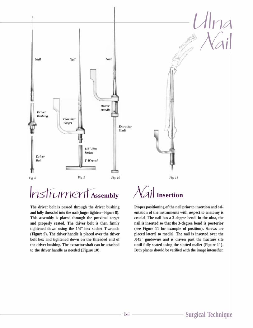
The driver bolt is passed through the driver bushingand fully threaded into the nail (finger tighten – Figure 8).This assembly is placed through the proximal targetand properly seated. The driver bolt is then firmlytightened down using the 1/4" hex socket T-wrench(Figure 9). The driver handle is placed over the driverbolt hex and tightened down on the threaded end ofthe driver bushing. The extractor shaft can be attachedto the driver handle as needed (Figure 10).
Insertion
Proper positioning of the nail prior to insertion and ori-entation of the instruments with respect to anatomy iscrucial. The nail has a 3-degree bend. In the ulna, thenail is inserted so that the 3-degree bend is posterior(see Figure 11 for example of position). Screws areplaced lateral to medial. The nail is inserted over the.045" guidewire and is driven past the fracture siteuntil fully seated using the slotted mallet (Figure 11).Both planes should be verified with the image intensifier.
Fig. 9Fig. 8
Instrument Nail
ProximalTarget
1/4" HexSocket
T-Wrench
Nail
Fig. 11Fig. 10
DriverBolt
DriverBushing
Nail
ExtractorShaft
DriverHandle
Nail

S.S.T.® Small Bone Locking Nail
Six
Fig. 12
IndicationsWhen there is an exaggerated bow of the nail and goodfill of the canal the nail fixator may not be needed.Placing the arm through the range of motion with thedriver attached will give the surgeon a good feel forwhether or not more fixation is needed.
Fixation InsertionFor fixation, the S.S.T. utilizes a unique locking devicethat surrounds the nail. The nail fixator is locked ontothe nail by a set screw (Figure 12).
With the nail and guidewire centered on the fluoro-scopic image, a separate .045" diameter x 6" guidewireis placed over the distal ulna to help locate the incisionsite for the fixator (Figure 13). Ideally, it should bepositioned 25mm from the tip of the nail. For distal
interlocking of the ulna, the ulnar nail is passed to thedistal aspect of the ulna. Care should be taken to ensureproper alignment of the coracoid process, 180-degreesto the ulna styloid. Once transverse plane alignment isobtained, the nail is located utilizing the image intensifier.A second .045" x 6" guidewire is then placed againstthe skin. An incision is made through the skin and sub-cutaneous tissues are spread to expose the ulnar cortex.
Fluoroscopic image should be utilized to confirm thelocation of the nail tip. With the nail fully seated, thedistal fixator should intersect the nail approximately25mm from the nail tip. After the entry point for the fix-ator is determined, a .045" x 6" guidewire is then passedacross the near cortex until it hits the nail (Figure 14).
Nail Fixator Insertion
Nail
SetScrew
Fixator
.045" DiameterGuide Wire
Fig. 13 Fig. 14 Fig. 15

Seven Surgical Technique
The nail and guidewire are backed up approximately4cm so the the .045" x 6" guidewire can be insertedacross the shaft and centered with the nail. Palpate theguidewire to ensure it is centered in the canal. A 2.7mmcannulated drill is placed over the guidewire to drill bothcortices in the central aspect of the shaft (Figure 15).
The .045" x 6" guidewire is removed. The near cortexonly must be enlarged by using the 3/16" pilot drill withstop (Figure 16).
Fixator location can be verified by advancing the nailand guidewire so that they are seen to pass by theenlarged near cortex. The nail and guidewire are pulledback prior to inserting the fixator. The 3.5mm tap isused to tap the far cortex.
The nail fixator is assembled onto the fixator T-wrench,using the stabilizer rod (Figure 17). The nail fixator isthreaded into the far cortex with the fixator T-wrench.The handle of the fixator T-wrench must be parallelwith the intramedullary nail for the opening in the distalfixator to align properly with the nail (Figure 18).
After the fixator is seated, the .045" x 50cm nail guidewireis passed through the opening in the fixator (Figure 19).Rotation of the fixator 45-degrees in both directions willverify that the guidewire has passed through the fixator.
UlnaNail
Fig. 17 Fig. 18 Fig. 19Fig. 16

S.S.T.® Small Bone Locking Nail
Eight
The intramedullary nail is advanced over the guidewireand through the fixator (Figure 20). Slight rotation ofthe fixator may be required. The fixator T-wrench andstabilizer rod is now removed. The set screw with nylonholder is started into the fixator by hand. The .050" hexdrive screwdriver then passes through the holder toadvance the set screw into final position in the fixator(Figure 21). Tightening is continued until the set screwis fully seated against the nail (Figure 22).
The guide bushing is placed into the guide tube and is in-serted through the hole in the proximal target (Figure 23).Using the guide tube for alignment, a stab incision ismade through the skin. In the ulna, the locking screwsare inserted at the proximal aspect of the ulna directedfrom lateral to medial. This decreases the risk of ulnarnerve injury. Using the guide tube for alignment, anincision is made at the tip of the guide and soft tissuesare spread until the cortex of the ulna is exposed. A.045" x 6" guidewire is then passed across both cortices(Figure 24).
The screw depth gauge is used to measure to proper screwlength (Figure 25). Note: guide bushing must rest againstthe bone for an accurate reading. A second .045" x 6"guidewire can be used to verify screw length.
Interlocking Screw Insertion
Fig. 20 Fig. 21 Fig. 22
Fig. 23
Fig. 24

Nine
UlnaNail
Surgical Technique
The end-cap is inserted with the cannulated 2.5mmhex drive screwdriver into the proximal end of the nail.The end cap and screwdriver are cannulated to go overa .045" diameter guidewire if so desired (Figure 28).
End-cap Placement
Fig. 25
Fig. 27
Fig. 26 Fig. 28
The guide bushing is removed. With the guidewire inplace, the 2.7mm cannulated drill is used to tap-drillfor the 3.5mm bone screw (Figure 26). The cannulated3.5mm bone screw is placed over the guidewire usingthe cannulated hex drive screwdriver (2.5mm hex)(Figure 27). The second locking screw is placed in asimilar fashion. Screw placements should be verified byimage before removing instruments. If necessary, a3.5mm cannulated tap is available to pre-tap for thebone screw.

S.S.T.® Small Bone Locking Nail
Ten
End Ulna Surgical Approach.See page 19 for Postoperative Care and Nail Removal.
Monteggia’s Dislocation Fracture
DefinitionMonteggia’s dislocation fracture is a fracture of theproximal 1/3 of the ulna, in association with an anterioror posterior dislocation of the radial head.
DiscussionThe S.S.T. Forearm Nail is an ideal choice for this type offracture. Proximal screw geometry in conjunction with theminimally invasive technique allows for an excellent result.
ObjectivesThe key to management of this fracture is to obtainlength and anatomical alignment of the ulna. Reductionof the radius first may help with alignment andreduction of the ulna.
Surgical TechniqueThe only variation from the normal ulnar technique isthat the entrance site is crucial to the alignment of theulna. The exact entry site is at the radial side of theolecranon, in line with the axis of the proximal ulnarfragment. The 3/32" guide pin is inserted further thannormal (2 to 4cm), this will act as a check to ensurethat the proper entry site has been obtained. If resistanceis met, then the guide pin is in the wrong plane. C-armpositioning is crucial in helping to determine theproper canal entry site. True laterals and A/Ps must beobtained in order to ensure proper guide pin placement.

Eleven Surgical Technique
Surgical Approach for Radius
For radial fixation, prior to incision a guidewire isplaced over the area of the distal wrist to ensure properposition of the entrance site in the longitudinal axis ofthe radius. A 1.5 to 2.5cm longitudinal incision is madeover the radial styloid. Subcutaneous tissues aredissected bluntly to avoid injury to the superficial
branches of the radial nerve. Soft tissues are retractedand the radial styloid entry site can now be identified(Figure 29). Caution should be taken with an entry sitetoo far distally as damage to the cartilage can occur.
Fig. 29
RadiusForearm
NailRadial Entry Site
S.S.T.® Small Bone Locking Nail
Twelve
Entry Point
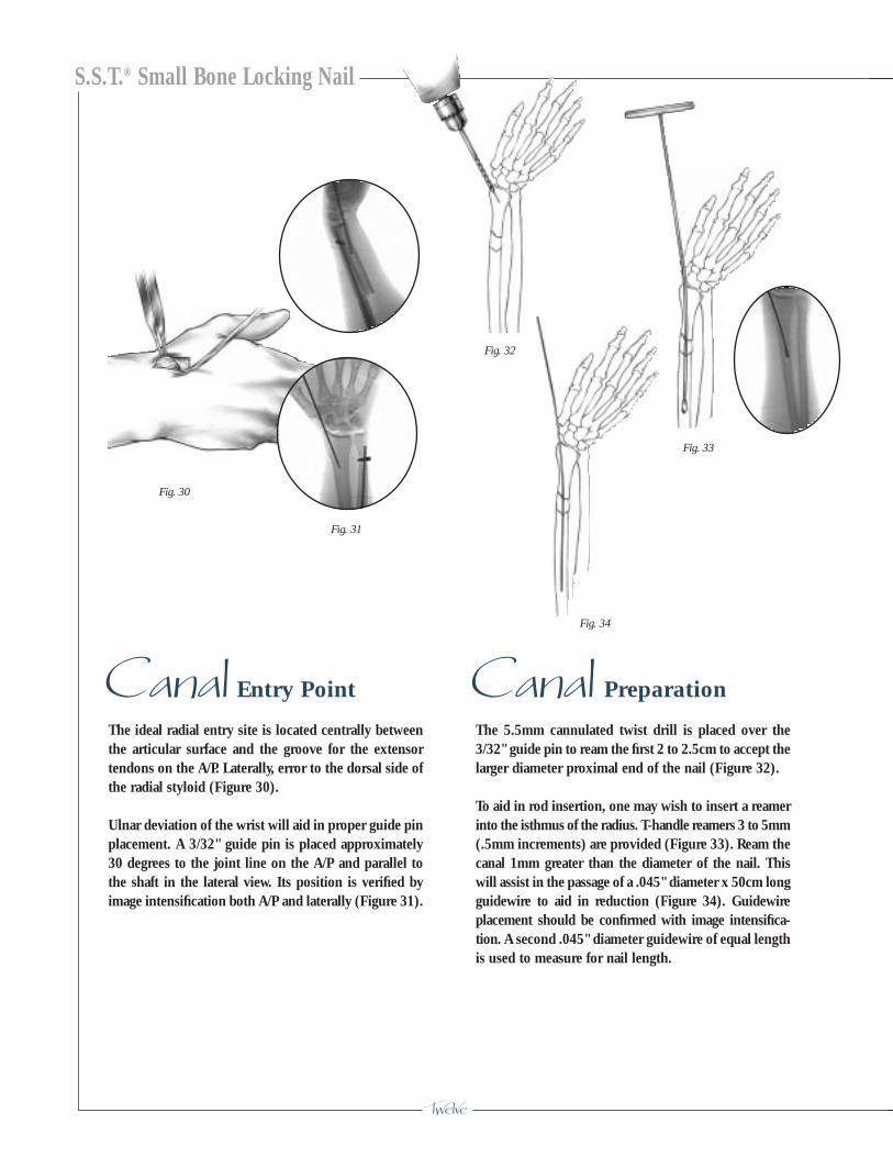
The ideal radial entry site is located centrally betweenthe articular surface and the groove for the extensortendons on the A/P. Laterally, error to the dorsal side ofthe radial styloid (Figure 30).
Ulnar deviation of the wrist will aid in proper guide pinplacement. A 3/32" guide pin is placed approximately30 degrees to the joint line on the A/P and parallel tothe shaft in the lateral view. Its position is verified byimage intensification both A/P and laterally (Figure 31).
Preparation
The 5.5mm cannulated twist drill is placed over the3/32" guide pin to ream the first 2 to 2.5cm to accept thelarger diameter proximal end of the nail (Figure 32).
To aid in rod insertion, one may wish to insert a reamerinto the isthmus of the radius. T-handle reamers 3 to 5mm(.5mm increments) are provided (Figure 33). Ream thecanal 1mm greater than the diameter of the nail. Thiswill assist in the passage of a .045" diameter x 50cm longguidewire to aid in reduction (Figure 34). Guidewireplacement should be confirmed with image intensifica-tion. A second .045" diameter guidewire of equal lengthis used to measure for nail length.
Canal Canal
Fig. 30
Fig. 33
Fig. 31
Fig. 32
Fig. 34

Thirteen Surgical Technique
Assembly
After nail length is determined, the driver bolt is passedthrough the driver bushing and fully threaded into thenail (finger tighten – Figure 35). This assembly isplaced through the proximal target and properly seated.The driver bolt is then firmly tightened down using the1/4" hex socket T-wrench (Figure 36). The driver handleis placed over the driver bolt hex and tightened downon the threaded end of the driver bushing (Figure 37).The extractor shaft can be attached to the driver handleas needed.
Note: Gentle bending of the radial nail may help thepassage of the nail within the intramedullary canal(Figure 38).
Insertion
Proper positioning of the nail prior to insertion andorientation of the instruments with respect to anatomyis crucial. The nail has a 3-degree bend and the nail isinserted so that the bend is facing laterally (toward thethumb). Screw orientation is from dorsal to palmer. Thenail is inserted over the proper guidewire and is drivenpast the fracture site until fully seated using the handpressure. If necessary, gently tap the nail until seated.Both planes should be verified using the image intensi-fier (Figure 39). Note: Do not use excessive force whendriving the nail, as it may cause the nail to deform.
Instrument Nail
Nail Nail
Fig. 35 Fig.36 Fig. 37Fig. 39
Fig. 38
RadiusNail
DriverBolt
DriverBushing
Nail
ProximalTarget
1/4" HexSocket
T-Wrench
ExtractorShaft
DriverHandle
S.S.T.® Small Bone Locking Nail
Fourteen
Fixator Insertion
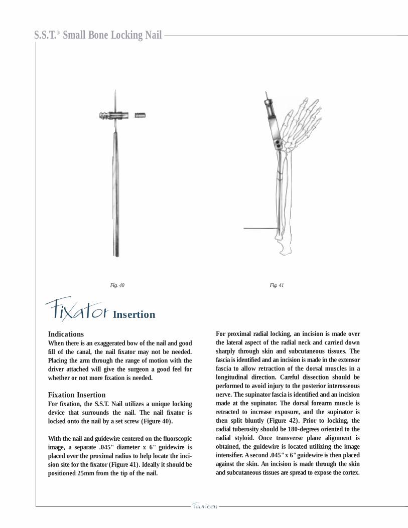
IndicationsWhen there is an exaggerated bow of the nail and goodfill of the canal, the nail fixator may not be needed.Placing the arm through the range of motion with thedriver attached will give the surgeon a good feel forwhether or not more fixation is needed.
Fixation InsertionFor fixation, the S.S.T. Nail utilizes a unique lockingdevice that surrounds the nail. The nail fixator islocked onto the nail by a set screw (Figure 40).
With the nail and guidewire centered on the fluorscopicimage, a separate .045" diameter x 6" guidewire isplaced over the proximal radius to help locate the inci-sion site for the fixator (Figure 41). Ideally it should bepositioned 25mm from the tip of the nail.
For proximal radial locking, an incision is made overthe lateral aspect of the radial neck and carried downsharply through skin and subcutaneous tissues. Thefascia is identified and an incision is made in the extensorfascia to allow retraction of the dorsal muscles in alongitudinal direction. Careful dissection should beperformed to avoid injury to the posterior interosseousnerve. The supinator fascia is identified and an incisionmade at the supinator. The dorsal forearm muscle isretracted to increase exposure, and the supinator isthen split bluntly (Figure 42). Prior to locking, theradial tuberosity should be 180-degrees oriented to theradial styloid. Once transverse plane alignment isobtained, the guidewire is located utilizing the imageintensifier. A second .045" x 6" guidewire is then placedagainst the skin. An incision is made through the skinand subcutaneous tissues are spread to expose the cortex.
Fig. 40 Fig. 41

Fifteen
RadiusNail
Surgical Technique
A fluoroscopic image should be utilized to confirm thelocation of the nail tip. With the nail fully seated, thenail fixator should intersect the nail approximately25mm from the nail tip. After the entry point for thefixator is determined, the nail and guidewire are backedup approximately 4cm so that a .045" x 6" guidewire
can be inserted across the shaft and centered with thenail. Palpate the guidewire to ensure it is centered inthe canal. A 2.7mm cannulated drill is placed over the.045" x 6" guidewire to drill both cortices in the centralaspect of the shaft (Figure 43).
Fig. 42 Fig. 43

S.S.T.® Small Bone Locking Nail
Sixteen
The .045" x 6" guidewire is removed. The near cortexonly must be enlarged by using the 3/16" pilot drill withstop (Figure 44).
Fixator location can be verified by advancing the nailand guidewire so that they are seen to pass by theenlarged near cortex. The nail and guidewire are pulledback prior to inserting the fixator. The 3.5mm tap isused to tap the far cortex.
The fixator is assembled onto the fixator T-wrench,using the stabilizer rod (Figure 45). The fixator isthreaded into the far cortex with the fixator T-wrench.The handle of the fixator T-wrench must be parallelwith the intramedullary nail for the opening in the fixatorto align properly with the nail (Figure 46).
After the fixator is seated, the .045" x 50cm nailguidewire is passed through the opening in the fixator(Figure 47). Rotation of the fixator 45-degrees in bothdirections will verify that the guidewire has passedthrough the fixator.
Fig. 44 Fig. 45
Fig. 46
Fig. 47
Seventeen
RadiusNail
Surgical Technique
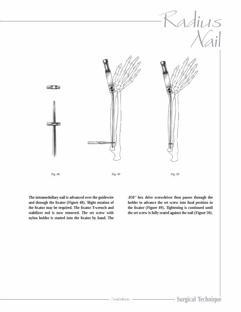
The intramedullary nail is advanced over the guidewireand through the fixator (Figure 48). Slight rotation ofthe fixator may be required. The fixator T-wrench andstabilizer rod is now removed. The set screw withnylon holder is started into the fixator by hand. The
.050" hex drive screwdriver then passes through theholder to advance the set screw into final position inthe fixator (Figure 49). Tightening is continued untilthe set screw is fully seated against the nail (Figure 50).
Fig. 48 Fig. 49 Fig. 50

S.S.T.® Small Bone Locking Nail
Eighteen
The guide bushing is placed into the guide tube and isinserted through a hole in the proximal target (Figure 51).Using the guide tube for alignment, a stab incision ismade through the skin. The subcutaneous tissues areretracted, and blunt dissection is carried out to the nearradial cortex. Under fluoroscopic control, a .045" x 6"guidewire is placed through the guide. It should passthrough the nail into the far cortex (Figure 52).
The screw depth gauge is used to measure the properscrew length (Figure 53). Note: The guide bushing mustrest against the bone for an accurate reading. A second.045" x 6" guidewire can be used to verify screw length.
The guide bushing is removed. With the guidewire inplace, the 2.7mm cannulated drill is used to tap-drillfor the 3.5mm bone screw (Figures 54). The cannulated3.5mm bone screw is placed over the guidewire usingthe cannulated 2.5mm hex drive screwdriver (Figure 55).
The second locking screw is placed in a similar fashion.Screw placements should be verified by image beforeremoving instruments. If necessary, a 3.5mm cannulatedtap is available to pre-tap for the bone screw.
Interlocking Screw Insertion
Fig. 51
Fig. 52
Fig. 55
Fig. 53
Fig. 54
Nineteen
RadiusNail
Surgical Technique
End-cap Placement
Fig. 56
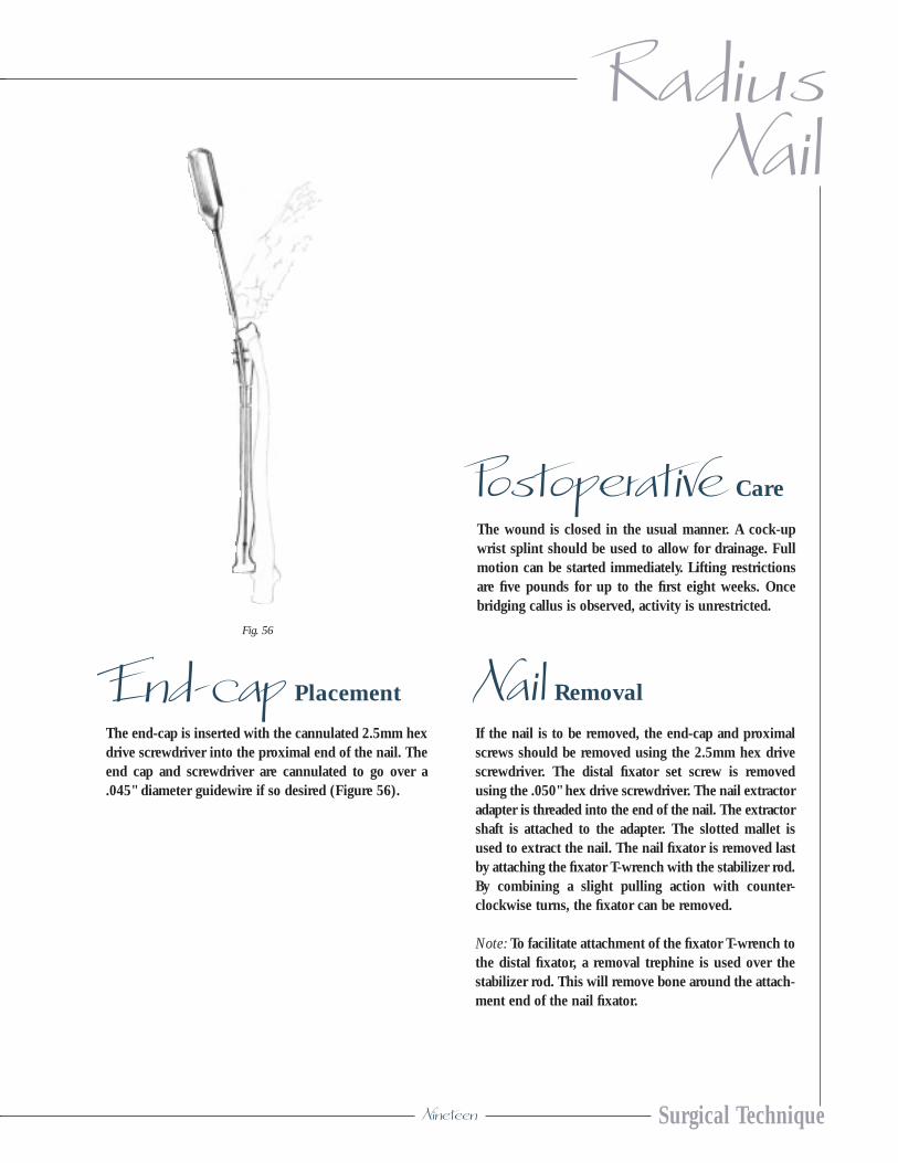
The end-cap is inserted with the cannulated 2.5mm hexdrive screwdriver into the proximal end of the nail. Theend cap and screwdriver are cannulated to go over a.045" diameter guidewire if so desired (Figure 56).
Care
The wound is closed in the usual manner. A cock-upwrist splint should be used to allow for drainage. Fullmotion can be started immediately. Lifting restrictionsare five pounds for up to the first eight weeks. Oncebridging callus is observed, activity is unrestricted.
Postoperative
Nail Removal
If the nail is to be removed, the end-cap and proximalscrews should be removed using the 2.5mm hex drivescrewdriver. The distal fixator set screw is removedusing the .050" hex drive screwdriver. The nail extractoradapter is threaded into the end of the nail. The extractorshaft is attached to the adapter. The slotted mallet isused to extract the nail. The nail fixator is removed lastby attaching the fixator T-wrench with the stabilizer rod.By combining a slight pulling action with counter-clockwise turns, the fixator can be removed.
Note: To facilitate attachment of the fixator T-wrench tothe distal fixator, a removal trephine is used over thestabilizer rod. This will remove bone around the attach-ment end of the nail fixator.

S.S.T.® Small Bone Locking Nail
Twenty
Proximal Target471314
T-Wrench 1/4" Hex Socket471316
Driver Handle471318
Guide Tube471320
Guide Bushing (.045" K-wire)471322
K-wire .045" x 6" Trocar Point Round Shank - Pk-626-351344
Cannulated Twist Drill 2.7mm x 127mm (5")471324
Part No. Description
244550 S.S.T.® End Cap
Part No. SS Cannulated Cortical Screws
244710 SS Cannulated 3.5 x 10mm244712 SS Cannulated 3.5 x 12mm244714 SS Cannulated 3.5 x 14mm244716 SS Cannulated 3.5 x 16mm244718 SS Cannulated 3.5 x 18mm244720 SS Cannulated 3.5 x 20mm244722 SS Cannulated 3.5 x 22mm244724 SS Cannulated 3.5 x 24mm244726 SS Cannulated 3.5 x 26mm244728 SS Cannulated 3.5 x 28mm244730 SS Cannulated 3.5 x 30mm244732 SS Cannulated 3.5 x 32mm244734 SS Cannulated 3.5 x 34mm
Ordering Information
Driver Bushing471310
Driver Bolt471312
S S T
InstrumentationNail Implants
Part No. S.S.T.® Nail Locking Device
244540 Forearm Distal Fixator244542 Set Screw with Holder
Part No. S.S.T.® Forearm Nails
244518 3.5mm x 18cm244520 3.5mm x 20cm244522 3.5mm x 22cm244524 3.5mm x 24cm244526 3.5mm x 26cm

Pilot Drill w/Stop 4/16” (4.8mm)7/64” (2.7mm) Pilot471352
Cannulated Tap 3.5mm471354
T-wrench for Fixator471356
Stabilizer Rod471358
Removal Trephine–Fixator471359
Hex Drive Screwdriver .050” Hex471360
Pin Placement Guide 3/32" Pin471362
Screw Depth Gage471364
Steinmann Pin 3/32" x 9" Trocar PointRound Shank27-361278 Pk.-6 non-sterile25-361278 Pk.-5 sterile
S.S.T. Instrument Case592026
Templates471305
ForearmNail
Surgical Technique
Cannulated Hex Drive Screwdriver 2.5mm471326
Cannulated Twist Drill 5.5mm x 178mm (7")471328
T-Handle Reamer 471330 3.0mm471332 3.5mm471334 4.0mm471336 4.5mm471338 5.0mm
Guidewire .045" x 19.6" (50cm) - Pk-6471340
Curved Awl471342
Extractor Shaft471344
Slotted Mallet471346
Nail Extractor Adaptor471348
Fracture Reduction Lever471350
32 28 24 20 16 12
30 26 22 18 14 10
Instrumentation cont’d

S.S.T.® Small Bone Locking Nail
P.O. Box 587, Warsaw, Indiana 46581-0587 • 219.267.6639 • ©1998 Biomet, Inc. All Rights Reserved web site: http://www.biomet.com • eMail: [email protected]
Form No. Y-BMT-565/093098/K