king county conveyance system...
TRANSCRIPT

KING COUNTY CONVEYANCE SYSTEM IMPROVEMENT PROJECT
TASK 260
SOUTH SAMMAMISH BASIN
TASK SUMMARY
October 2003


TABLE OF CONTENTS
South Sammamish Basin Background Information Summary .........................................1
Basin Topography and Land Use.............................................................................................1
Basin Population Forecasts ......................................................................................................3
Planning Area Issues and Problems .........................................................................................4
Wastewater Conveyance Facility Review ............................................................................4
Sammamish Plateau WSD Facilities........................................................................................5
Issaquah Wastewater Facilities ................................................................................................5
Bellevue Wastewater Facilities ................................................................................................6
King County Wastewater Treatment Division Facilities .........................................................6 Issaquah Creek Interceptor .............................................................................................6 Issaquah Interceptor........................................................................................................6 Sunset Pump Station and Force Main ............................................................................7 Heathfield Pump Station and Force Main ......................................................................7 Eastgate Trunk................................................................................................................7 Lake Hills Boulevard Siphon .........................................................................................8 Lake Hills Interceptor.....................................................................................................8
Conveyance System Improvement Alternatives..................................................................8
South Sammamish Basin Conveyance System Capacities ......................................................9
Development of Conveyance System Improvement Alternatives .........................................11 Alternative A: Diverting a Portion of the Sammamish Plateau WSD Flow Northward to the NE Sammamish Interceptor .............................................................11 Alternative B: Diverting Wastewater Away from the Sunset Pump Station Force Main, North to the Lake Hills Trunk..................................................................11 Alternative C: Using Storage Tanks or Tunnels to Attenuate Peak Flow...................12 Alternative D: Divert Flow Along the I-90 Right-of-Way to the Eastside Interceptor ......................................................................................................12 Alternative E: Construct a Land-Based Sewer to Bypass the Issaquah Interceptor Section 1 .......................................................................................................................12 Alternative F: Increase capacity of Sunset and Heathfield Pump Stations and Eastgate Trunk..............................................................................................................13
Page i p:\17226 king co., csi\wp\south sammamish\southsammtsk260_final(2).doc
King County Conveyance System Improvements
Alternative G: I/I Control Under the County’s Regional I/I Program........................ 13 Alternative H: Reclaimed Water Production and Discharge in the Basin .................. 13 Alternative I: Diverting the Issaquah Highlands Away from the Issaquah Creek Interceptor .................................................................................................................... 14
Packaging Alternatives for a Complete Solution .................................................................. 15 Package 1 ..................................................................................................................... 15 Package 2 ..................................................................................................................... 16
Selecting a Working Alternative ........................................................................................... 16
Refining the Working Alternative ......................................................................................... 18
Analysis of Components of the Working Alternative ........................................................... 20 Northward Diversion of Some Sammamish Plateau Flow .......................................... 20 Issaquah Highlands Relief Sewer ................................................................................ 23 Peak Flow Storage in Issaquah and Sammamish Plateau............................................ 26 Minor Upgrades to the Sunset PS and Heathfield PS .................................................. 26
Responding to Workshop Issues ........................................................................................... 26 Impacts of Peak Wastewater Flow that Vary from Current Projections...................... 27 Operation and Maintenance Assumptions ................................................................... 29 Possibility of Increasing Storage to Eliminate the Northern Diversion....................... 30
Implementing the Working Alternative ............................................................................ 31
Preliminary Cost Estimates for Working Alternative Key Components............................... 31
Implementation Schedule ...................................................................................................... 33
Issues for Predesign Team..................................................................................................... 35
Page ii p:\17226 king co., csi\wp\south sammamish\southsammtsk260_final(2).doc
King County Conveyance System Improvements
LIST OF TABLES
Table 1. August 2000 PSRC/KCWTD South Sammamish Basin Forecasts ..........................3
Table 2. CSI Alternatives for the South Sammamish Basin .................................................15
Table 3. Future Capacity Shortfalls for Existing Facilities...................................................19
Table 4. Flow Reduction or Capacity Increase via the Working Alternative .......................19
Table 5. Northward Diversion Gravity Pipe Section Profile and Diameter..........................23
Table 6. Issaquah Highlands Relief Sewer Piping Summary ...............................................25
Table 7. Future Growth and Flow Scenarios for Issaqyuah and Sammamish Plateau .........28
Table 8. Schedule of Facilities Reaching Capacity...............................................................29
Table 9. Storage Facility O&M Cost Estimate Inputs ...........................................................30
Table 10. Updated Construction Cost for Northern Diversion and Issaquah Highlands Relief Sewer..........................................................................32
Table 11. Working Alternative Project Costs .......................................................................32
Page iii p:\17226 king co., csi\wp\south sammamish\southsammtsk260_final(2).doc
King County Conveyance System Improvements
LIST OF FIGURES
Figure 1. South Sammamish Basin Boundaries ..................................................................... 2
Figure 2. Summary of Flow Projections for the South Sammamish Basin............................ 9
Figure 3. Summary of Capacity Overview for South Sammamish Basin Facilities ............ 10
Figure 4. Working Alternative Component Conveyance Upgrades..................................... 17
Figure 5. Point of Northward Diversion of Sammamish Plateau WSD Flow...................... 21
Figure 6. Ground Surface Profile for Alternative A Routes................................................. 21
Figure 7. Possible Routes for an Issaquah Highlands Relief Sewer..................................... 24
Figure 8. Ground Surface and Pipeline Profiles for Issaquah Highlands Relief Sewer ....... 25
Figure 9. Range of Flows in South Sammamish Basin ........................................................ 28
Figure 2. Working Alternative System Capacity: Issaquah Interceptor Section 1.............. 34
Figure 3. Working Alternative System Capacity: Sunset and Heathfield P.S..................... 34
Page iv p:\17226 king co., csi\wp\south sammamish\southsammtsk260_final(2).doc

SOUTH SAMMAMISH BASIN TASK SUMMARY
The Conveyance System Improvement Project’s Task 200 series of reports on the South Sammamish Basin investigates the regional wastewater service needs for the five King County sewer basins located near the south end of Lake Sammamish. The first three tasks, Tasks 210, 220, and 230, assembled background information on existing wastewater service, wastewater facilities, and the natural environment within the basin. The Task 240 report proposed a set of alternatives to help meet the wastewater capacity needs in the basin throughout the planning window, which extends to 2050. Following the County’s selection of a Working Alternative at a task workshop, the project team refined that Working Alternative package of improvements and developed cost estimates and implementation schedules for the Working Alternative components in Task 250. This Task 260 report summarizes all of the work Task 210 through 250.
SOUTH SAMMAMISH BASIN BACKGROUND INFORMATION SUMMARY
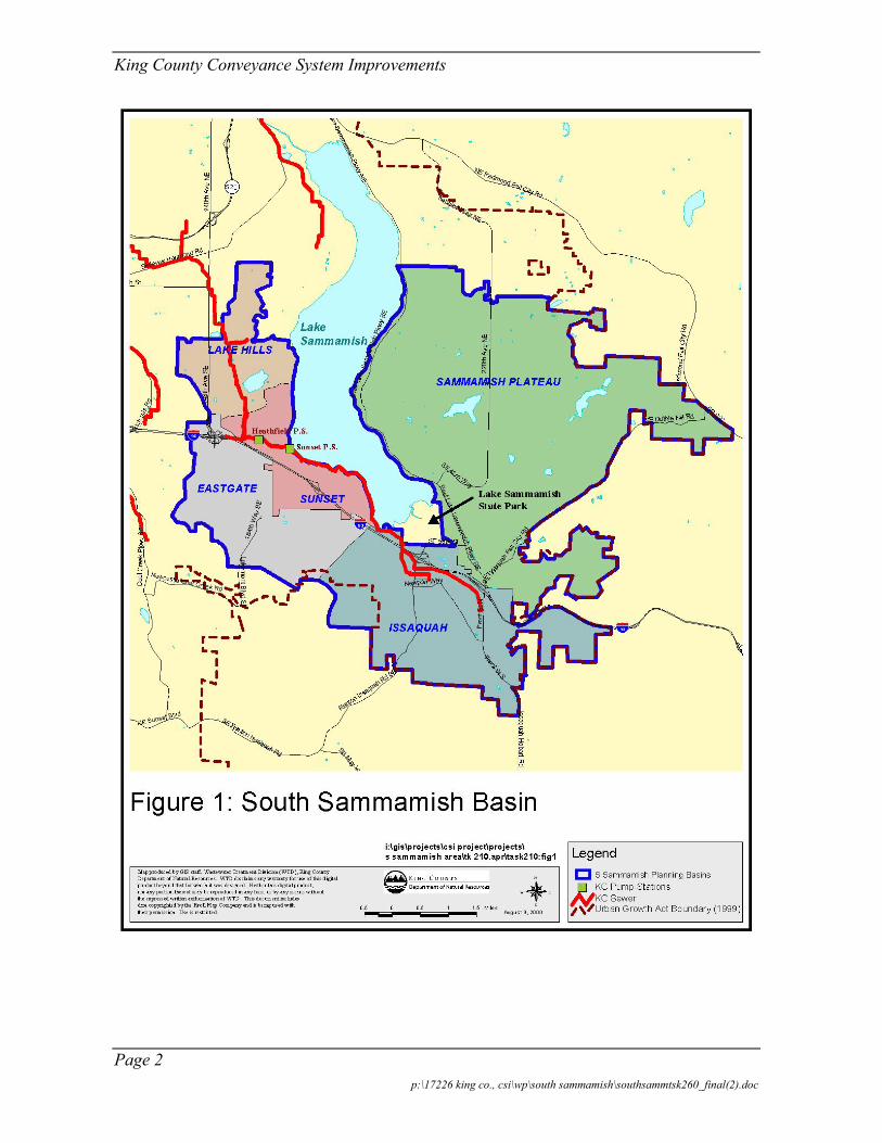
The South Sammamish Basin is located in east King County around the southern half of Lake Sammamish. The basin covers nearly 48 square miles. Figure 1 shows the geographical extent of the basin, which includes parts of three incorporated cities (Bellevue, Issaquah, and Sammamish) and unincorporated King County, and covers five King County drainage basins: Lake Hills, Eastgate, Sunset, Issaquah, and Sammamish Plateau.
King County Wastewater Treatment Division (KC WTD) facilities in the basin collect flows from the Sammamish Plateau Water and Sewer District (Sammamish Plateau WSD) on the east side of Lake Sammamish, the City of Issaquah at the south end of the lake, and parts of the City of Bellevue to the west of Lake Sammamish. KC WTD wastewater basins and local agency boundaries are also shown on Figure 1.
Basin Topography and Land Use
Much of the Lake Sammamish basin is relatively flat, but steep slopes (from 20 to 40 percent) predominate at the south end of the lake, near Issaquah and Eastgate. The basin elevation varies from over 1,900 feet (at the top of Squak Mountain in Issaquah) to 26 feet along the Lake Sammamish shoreline. The topography of the basin directly influences the pattern of development. Steep slopes preclude development in parts of the basin, forcing that development to the flatter areas along the lake, along stream valleys, and on upland plateaus.
Page 1 p:\17226 king co., csi\wp\south sammamish\southsammtsk260_final(2).doc
King County Conveyance System Improvements
Page 2 p:\17226 king co., csi\wp\south sammamish\southsammtsk260_final(2).doc

King County Conveyance System Improvements
The basin is currently predominantly zoned for residential development, but substantial commercial areas exist in downtown Issaquah, near the Eastgate interchange in Bellevue, and along 228th Street in Sammamish. Most of Bellevue lying within the South Sammamish Basin has been developed for some time, and the rapid growth that Bellevue experienced in the 1970s and 1980s has slowed. Growth rates in Issaquah and Sammamish are among the highest in King County. The Sammamish Plateau is expected to develop to the extent of developable land. Two large developments underway in Issaquah, but no further large scale developments are planned there.
Basin Population Forecasts
The Puget Sound Regional Council (PSRC) prepares population and employment forecasts for use by local governments in King County. The forecasts are developed using the agency’s Growth management Forecasting Model. Table 1 below summarizes the August 2000 PSRC/KCWTD forecasts for the South Sammamish Basin.
Table 1. August 2000 PSRC/KCWTD South Sammamish Basin Forecasts
Estimates for Year 2000
Planning Sub-Basin Sub-Basin Area1
(acres) Residential Population
Commercial Employees
Industrial Employees
Lake Hills 1,910 13,471 7,217 409 Eastgate 3,045 14,139 3,413 308 Sunset 1,571 9,287 3,239 2,440 Issaquah 6,170 9,432 7,130 1,011 Sammamish Plateau 10,816 28,123 6,353 204 Totals 23,512 74,452 27,352 4,372
Forecasts for Year 2050
Sub-Basin Area1
(acres) Residential Population
Commercial Employees
Industrial Employees
Lake Hills 1,910 13,940 9,848 453 Eastgate 3,045 19,652 4,925 305 Sunset 1,571 10,953 4,230 2,405 Issaquah 6,170 14,096 12,231 1,331 Sammamish Plateau 10,816 41,894 10,978 617 Totals 23,512 100,535 42,212 5,111
1 Sub-Basin Area includes only those portions of the basin inside the Urban Growth Area Boundary.
Local sewerage agencies who serve the South Sammamish Basin must plan to meet their own immediate and long-term agency needs. Those agencies have developed forecasts for their own jurisdictions. The King County forecasts for Bellevue compare favorably with the growth expectations of Bellevue utilities’ personnel. Sewer planning studies recently completed or currently underway by Issaquah and Sammamish Plateau WSD suggest that
Page 3 p:\17226 king co., csi\wp\south sammamish\southsammtsk260_final(2).doc

King County Conveyance System Improvements
the current PSRC/KCWTD forecasts do not fully reflect the rapid growth taking place in their parts of the South Sammamish Basin. These local agencies ultimately expect more residents in the basin, and they expect them there sooner than PSRC/KCWTD forecasts indicate. However, because conveyance facilities are sized for peak rather than average flows, and because wet weather infiltration and inflow are the primary components of those peak flows, differences in forecasted population will have a relatively minor impact on peak flows and the facilities needed to convey them.
Planning Area Issues and Problems
The following list briefly summarizes areas of concern in the South Sammamish Basin:
1. Development and population growth will cause wastewater flows from the South Sammamish Basin to exceed system capacity within the next 20 years or less. Capacity in the Issaquah Creek Interceptor could be exceeded by or before 2010.
2. In addition to population growth, I/I is likely increasing within the basin. Issaquah and Bellevue staff indicate that many of their sewers are old and show signs of deterioration. Also, during wet weather periods, much of the sewer systems in the Bellevue lakeside sub-basins and in downtown Issaquah experience excessive inflow. I/I removal projects have the potential to reduce peak flows, but renovation of trunk sewers might not solve Issaquah’s I/I problem because much of the I/I comes from leaking private lateral sewers upstream of the trunk sewers. Issaquah has undertaken I/I removal projects (e.g., sliplining city trunk sewers in downtown), but because Issaquah has performed no post-rehabilitation flow monitoring, the effectiveness of such projects is uncertain. It seems likely that flows will have to be diverted out of the basin, or additional conveyance will have to be provided if sanitary sewer overflows (SSOs) are to be avoided following major storm events in the coming decades.
WASTEWATER CONVEYANCE FACILITY REVIEW
The wastewater conveyance system serving the South Sammamish Basin generally drains from east to west. The Sammamish Plateau WSD, and the Cities of Issaquah and Bellevue collect sanitary sewage from their local sewer systems and transport that sewage to King County WTD facilities. The Task 220 report provides summary descriptions of the South Sammamish WSD, Issaquah, and Bellevue wastewater facilities that drain to King County facilities. The Task 220 report also describes the major King County wastewater facilities serving the South Sammamish Basin, including (from upstream to down) the Issaquah Creek Interceptor, Issaquah Interceptor, the Sunset and Heathfield Pump Stations, the Eastgate Trunk, the Lake Hills Boulevard Siphon, and the Lake Hills Interceptor. Wastewater from the basin eventually flows to the Eastside Interceptor, which conveys those flows to the King County WTD South Treatment Plant at Renton for treatment and discharge.
Page 4 p:\17226 king co., csi\wp\south sammamish\southsammtsk260_final(2).doc
King County Conveyance System Improvements
Sammamish Plateau WSD Facilities
The Sammamish Plateau WSD service area extends from the eastern edge of Lake Sammamish eastward beyond the Urban Growth Area (UGA) boundary. All wastewater collected within the district presently flows south, toward the Issaquah Interceptor.
The Sammamish Plateau WSD includes about 110 miles of pipeline. Local sewers range in diameter from 8 inches to 12 inches, although some sewer mains are as large as 36 inches in diameter. According to available data, approximately 10 percent of the District’s sewers are larger than 12 inches in diameter. The sewer system is expanding as new development occurs on the plateau. The Sammamish Plateau WSD uses 16 lift stations to move wastewater to the larger mains.
Although sewer construction materials vary, most of newer sewer mains and laterals are constructed of PVC or HDPE. Because of the District’s rapid growth, most of pipes are relatively new. The oldest pipes in the District are approximately 25 years old, but most pipes are less than 15 years old. Because the pipes are so new, I/I contribution from the Sammamish Plateau WSD is relatively low.
Issaquah Wastewater Facilities
The City of Issaquah’s collection system consists of gravity sewers that drain to the northwest into either the Issaquah Interceptor or the Issaquah Creek Interceptor. Issaquah’s sewers range up to 18 inches in diameter, with most sewers measuring 8 inches in diameter. The City's sewer service area flows are divided roughly evenly between the two King County WTD interceptors. Generally, areas east of NW Newport Way flow to the Issaquah Creek Interceptor, while the remaining service area flows to the Issaquah Interceptor. One lift station and a 6-inch diameter force main connect two small sub-basins (the sites of the Holiday Inn and Pickering Place Retail Center) located north of I-90 to the Issaquah Interceptor. The City’s local gravity sewers connect to the King County WTD interceptors in a number of different locations.
The City of Issaquah has some of the oldest sewers in the South Sammamish Basin. Some of the downtown sewers are more than 60 years old, and sewer overflows during sever storms has occurred. In an effort to reduce the amount of infiltration and inflow (I/I) entering the sewer system, Issaquah lined all older sewer mains in-situ with an impregnated resin. The rehabilitation was limited to sewer mains.
Presently, there are two major residential developments planned for Issaquah: the East Village development and the Issaquah Highlands development. These two developments, together with small pockets of development elsewhere in the Issaquah service area, could cause the sewer service area population to double by 2010. By then, the service area will have reached the maximum development permitted under present zoning and long range plans. The two large, new developments will increase average flows, but the flows will be routed so as to limit impacts on existing local sewers, particularly the capacity limited
Page 5 p:\17226 king co., csi\wp\south sammamish\southsammtsk260_final(2).doc
King County Conveyance System Improvements
downtown sewers. Peak flow increases are expected to be modest as the pipe being installed to serve those developments should not admit significant I/I contributions.
Bellevue Wastewater Facilities
The City of Bellevue operates one of the largest sewage collection systems in King County, covering more than 40 square miles, of which more than 8 square miles (5,400 acres) lie within the downstream portion of the South Sammamish Basin. Most of Bellevue within the South Sammamish Basin has been fully developed, and population growth is not a concern in the fully-developed areas.
The 1,430 acre Cougar Mountain Sub-Basin, the largest of Bellevue’s sub-basins within the South Sammamish Basin planning area, is one of the last sub-basins within the Bellevue planning area to be developed. Build out of Cougar Mountain is expected within the next 10 years and will cause an increase in flows to the Sunset and Heathfield Pump Stations. Cougar Mountain build out will not impact flows in the Issaquah Interceptor, however.
King County Wastewater Treatment Division Facilities
King County owns and maintains a system of interceptor sewers, an inverted siphon, and pump stations in the South Sammamish Basin. The key characteristics of the sewers and pump stations, shown in Figure 2, are described in the following sections. The facilities are discussed in order from upstream to downstream locations.
Issaquah Creek Interceptor
The Issaquah Creek Interceptor, which serves the eastern half of the City of Issaquah, was constructed in 1982 to relieve sections of the Issaquah Interceptor that were flowing near capacity through the city during wet weather. The interceptor is 21 inches in diameter and extends for approximately two miles along NW Gilman Boulevard before discharging to the Issaquah Interceptor at manhole R17-37, which is located near I-90.
Issaquah Interceptor
The Issaquah Interceptor is the primary conveyance facility draining the southern and western parts of the South Sammamish Basin. The Issaquah Interceptor drains the western part of the City of Issaquah by numerous local connections and receives flow from the rest of the Issaquah system via discharge from the Issaquah Creek Interceptor approximately one mile from its upstream end. After receiving the Issaquah Creek Interceptor flows, the Issaquah Interceptor runs approximately one-half mile to Lake Sammamish and then three miles in Lake Sammamish to the Sunset Pump Station.
Page 6 p:\17226 king co., csi\wp\south sammamish\southsammtsk260_final(2).doc
King County Conveyance System Improvements
The Issaquah Interceptor was constructed in 1962 of reinforced concrete pipe. Upstream of the confluence with the Issaquah Creek Interceptor, the pipe diameter ranges from 21 to 24 inches. Downstream of that confluence, the pipe is 48 inches in diameter. The lake line portion of the interceptor has two flushing stations that allow the introduction of freshwater from Lake Sammamish during periods of low flow to reduce odor. The interceptor also has two emergency overflow lines to protect downstream equipment, including the Sunset Pump Station.
Sunset Pump Station and Force Main
At the downstream (northwest) end of the Issaquah Interceptor is the Sunset Pump Station. Originally constructed as an interim pump station in the 1960's pending completion of a planned 42 mgd Vasa Park Pump Station, the station was rebuilt in 1987 in lieu of construction of the Vasa Park station.
The Sunset Pump Station receives influent flows from the Issaquah interceptor and from a 10-inch diameter and a 14-inch diameter connection from the City of Bellevue’s Vasa Park and Sammamish Sub-Basins. Four variable-speed driven pumps (two 3.8 mgd capacity centrifugal screw pumps and two 10.8 mgd vertical non-clog centrifugal pumps) provide about 18 mgd of pumping capacity. Two 3,220-foot long ductile iron force mains (12-inches and 24-inches in diameter) carry wastewater from the Sunset Pump Station to the Heathfield Pump Station. The capacity of the Sunset Pump Station is sufficient to meet present wet weather flow demand. There have been no identified discharges in the past several years from the two overflow structures associated with the Sunset Pump Station.
Heathfield Pump Station and Force Main
The Heathfield pump station is located just north of Interstate 90 in Bellevue. The pump station receives all flow from the two Sunset force mains, as well as flows from a 10-inch diameter local sewer that drains a few blocks of Bellevue's Metro 56 basin.
The Heathfield pump station is similar to the Sunset pump station. Both were built in the 1960's and rebuilt in 1980's. Both stations were equipped with identical variable frequency-driven pumps, and both stations have identical pumping capacities (18 mgd). Like Sunset, the Heathfield pump station discharges via two force mains (one a 12-inch diameter pipe, the other 24 inches in diameter). The Heathfield force mains are 1,650 feet long and discharge to the Eastgate Trunk. In the absence of a power failure, the capacity of the Heathfield Pump Station is sufficient to convey current peak wet weather flows.
Eastgate Trunk
Wastewater through the much of the Bellevue section of the South Sammamish Basin is conveyed by the Eastgate Trunk. The first one-third mile of the trunk consists of 24-inch diameter pipe, constructed in 1964, that picks up relatively small flows from local Bellevue sewers. After the first one-third mile section, the capacity and flows in the Eastgate Trunk
Page 7 p:\17226 king co., csi\wp\south sammamish\southsammtsk260_final(2).doc
King County Conveyance System Improvements
increase substantially. The Eastgate Trunk conveys all wastewater from the Sammamish Plateau WSD, Issaquah, and Bellevue’s the Eastgate and Sunset Basins in parallel gravity sewers.
When the original sections of the Eastgate Trunk were built in 1964, the northward sections of the trunk ranged in diameter from 22 to 36 inches, with most sections using 24-inch diameter pipe. The Eastgate Trunk was paralleled in the 1980's to coincide with the expanded capacities of the rebuilt Sunset and Heathfield Pump Stations. The parallel sewer ranges in size from 24 to 48-inch diameter, with the majority of pipe sections measuring 36 inches in diameter. The parallel pipes extend between 1.5 and 2 miles before discharging to the Lake Hills Interceptor at manhole R03-49. The route of the trunk is congested, with three sewer pipes using the same right-of-way. In (a local Bellevue trunk parallels the Eastgate Trunk). Alternatives to expand system conveyance capacity in that area must consider the utility congestion along the Eastgate Trunk route.
Lake Hills Boulevard Siphon
The Lake Hills Boulevard Siphon consists of twin 10-inch diameter pipes that form a one-third mile long, inverted siphon to connect a local sewer line with the upstream end of the Lake Hills Interceptor. The forebay of the siphon is equipped with a slide gate structure to isolate flow to either siphon line. The low point in the siphon is connected to the surface by a cleanout/blowoff valve that is used to drain the siphon lines.
Lake Hills Interceptor
The Lake Hills Interceptor begins at the discharge of the Eastgate Interceptor and Lake Hills Boulevard Siphon and transports all South Sammamish Basin wastewater out of the basin. Within the South Sammamish Basin, the Lake Hills Interceptor consists of 2,100 feet of 48-inch diameter pipe. Downstream of the South Sammamish Basin, the Lake Hills Interceptor continues for another 3.5 miles before discharging to the Eastside Interceptor, which is the major influent sewer to King County's South Plant at Renton.
CONVEYANCE SYSTEM IMPROVEMENT ALTERNATIVES
Task 240 required the project team to develop and evaluate preliminary alternatives for solving the wastewater conveyance capacity problems in the South Sammamish Basin. Using geographical information systems (GIS) data and population forecasts, King County developed flow projections for the basin in future years. The project team then used the County flow projections to develop possible alternatives for a conveyance system that would be able to convey the 20-year peak flow.
Page 8 p:\17226 king co., csi\wp\south sammamish\southsammtsk260_final(2).doc
King County Conveyance System Improvements
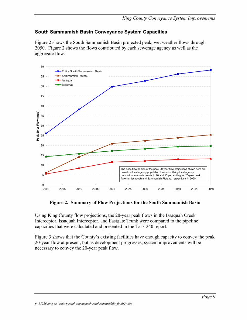
South Sammamish Basin Conveyance System Capacities
Figure 2 shows the South Sammamish Basin projected peak, wet weather flows through 2050. Figure 2 shows the flows contributed by each sewerage agency as well as the aggregate flow.
0
5
10
15
20
25
30
35
40
45
50
55
60
2000 2005 2010 2015 2020 2025 2030 2035 2040 2045 2050
Peak
20-
yr F
low
(mgd
)
Entire South Sammamish BasinSammamish PlateauIssaquahBellevue
The base flow portion of the peak 20-year flow projections shown here are based on local agency population forecasts. Using local agency population forecasts results in 10 and 15 percent higher 20-year peak flows for Issaquah and Sammamish Plateau, respectively in 2050.
Figure 2. Summary of Flow Projections for the South Sammamish Basin
Using King County flow projections, the 20-year peak flows in the Issaquah Creek Interceptor, Issaquah Interceptor, and Eastgate Trunk were compared to the pipeline capacities that were calculated and presented in the Task 240 report.
Figure 3 shows that the County’s existing facilities have enough capacity to convey the peak 20-year flow at present, but as development progresses, system improvements will be necessary to convey the 20-year peak flow.
Page 9 p:\17226 king co., csi\wp\south sammamish\southsammtsk260_final(2).doc
King County Conveyance System Improvements
Sunset PS
Heathfield PS
To Eastside InterceptorLake Hills Interceptor
Eastgate Trunk
Issaquah Int.Sec.1
IssaquahInt. Sec.2
IssaquahCreek Int.
Connection from Local SewerKC Sewer: Over Capacity 2010
SammamishPlateau
(to MH R17-36)
Issaquah 1Issaquah 2
Bellevue 1 includes Metro 57,Cougar Mountain, Sammamishand Vasa Park sub-basins
Bellevue 2 includes Eastgate,Leawood and Metro 56 sub-basins
Bellevue 3 includes South Larsen Lake,Lake Hills and Phantom Lake sub-basins Bellevue 1
Bellevue 2
Bellevue 3
Lake Hills Blvd. Siphon
To MH R17-56ATo MH R17-42 or 36
MH R17-28 to 03
MH R11-71
MH R11-54A or 47
KC Sewer: Over Capacity 2020KC Sewer: Capacity OK in 2050
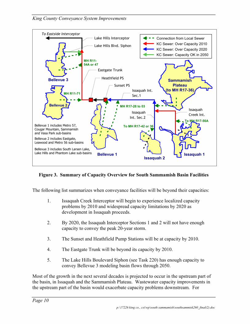
Figure 3. Summary of Capacity Overview for South Sammamish Basin Facilities
The following list summarizes when conveyance facilities will be beyond their capacities:
1. Issaquah Creek Interceptor will begin to experience localized capacity problems by 2010 and widespread capacity limitations by 2020 as development in Issaquah proceeds.
2. By 2020, the Issaquah Interceptor Sections 1 and 2 will not have enough capacity to convey the peak 20-year storm.
3. The Sunset and Heathfield Pump Stations will be at capacity by 2010.
4. The Eastgate Trunk will be beyond its capacity by 2010.
5. The Lake Hills Boulevard Siphon (see Task 220) has enough capacity to convey Bellevue 3 modeling basin flows through 2050.
Most of the growth in the next several decades is projected to occur in the upstream part of the basin, in Issaquah and the Sammamish Plateau. Wastewater capacity improvements in the upstream part of the basin would exacerbate capacity problems downstream. For
Page 10 p:\17226 king co., csi\wp\south sammamish\southsammtsk260_final(2).doc
King County Conveyance System Improvements
example, capacity upgrades to the Issaquah Creek and Issaquah Interceptors would increase capacity shortfalls at the Sunset and Heathfield Pump Stations. Upgrading the pump stations would require upgrades along the Eastgate Trunk. However, the sequential upsizing/paralleling of existing facilities could be minimized with a program that includes selected capacity upgrades, flow diversions, and demand management.
Development of Conveyance System Improvement Alternatives
The CSI project team developed several alternatives to help reduce conveyance system overflows to once per 20 years through 2050. These alternatives rely on increased conveyance capacity, flow management, and/or flow diversion to help manage flow demand. The individual alternatives would generally not by themselves solve all conveyance problems in the South Sammamish Basin. Instead, they would address specific problems, and by combining multiple alternatives into packages, a complete solution for the basin can be developed.
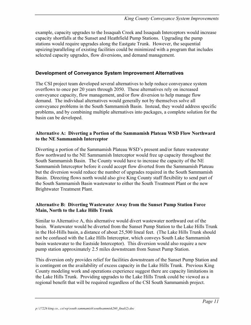
Alternative A: Diverting a Portion of the Sammamish Plateau WSD Flow Northward to the NE Sammamish Interceptor
Diverting a portion of the Sammamish Plateau WSD’s present and/or future wastewater flow northward to the NE Sammamish Interceptor would free up capacity throughout the South Sammamish Basin. The County would have to increase the capacity of the NE Sammamish Interceptor before it could accept flow diverted from the Sammamish Plateau but the diversion would reduce the number of upgrades required in the South Sammamish Basin. Directing flows north would also give King County staff flexibility to send part of the South Sammamish Basin wastewater to either the South Treatment Plant or the new Brightwater Treatment Plant.
Alternative B: Diverting Wastewater Away from the Sunset Pump Station Force Main, North to the Lake Hills Trunk
Similar to Alternative A, this alternative would divert wastewater northward out of the basin. Wastewater would be diverted from the Sunset Pump Station to the Lake Hills Trunk in the Hol-Hills basin, a distance of about 25,500 lineal feet. (The Lake Hills Trunk should not be confused with the Lake Hills Interceptor, which conveys South Lake Sammamish basin wastewater to the Eastside Interceptor). This diversion would also require a new pump station approximately 2.5 miles downstream from Sunset Pump Station.
This diversion only provides relief for facilities downstream of the Sunset Pump Station and is contingent on the availability of excess capacity in the Lake Hills Trunk. Previous King County modeling work and operations experience suggest there are capacity limitations in the Lake Hills Trunk. Providing upgrades to the Lake Hills Trunk could be viewed as a regional benefit that will be required regardless of the CSI South Sammamish project.
Page 11 p:\17226 king co., csi\wp\south sammamish\southsammtsk260_final(2).doc
King County Conveyance System Improvements
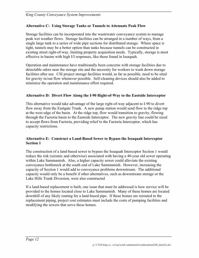
Alternative C: Using Storage Tanks or Tunnels to Attenuate Peak Flow
Storage facilities can be incorporated into the wastewater conveyance system to manage peak wet weather flows. Storage facilities can be arranged in a number of ways, from a single large tank to a series of wide pipe sections for distributed storage. Where space is tight, tunnels may be a better option than tanks because tunnels can be constructed in existing street right-of-way, limiting property acquisition needs. Typically, storage is most effective in basins with high I/I responses, like those found in Issaquah.
Operation and maintenance have traditionally been concerns with storage facilities due to detectable odors near the storage site and the necessity for workers to wash down storage facilities after use. CSI project storage facilities would, as far as possible, need to be sited for gravity in/out flow whenever possible. Self-cleaning devices should also be added to minimize the operation and maintenance effort required.
Alternative D: Divert Flow Along the I-90 Right-of-Way to the Eastside Interceptor
This alternative would take advantage of the large right-of-way adjacent to I-90 to divert flow away from the Eastgate Trunk. A new pump station would send flow to the ridge top at the west edge of the basin. At the ridge top, flow would transition to gravity, flowing through the Factoria basin to the Eastside Interceptor. The new gravity line could be sized to accept flows from Factoria, providing relief to the Factoria Interceptor, which has capacity restrictions.
Alternative E: Construct a Land-Based Sewer to Bypass the Issaquah Interceptor Section 1
The construction of a land-based sewer to bypass the Issaquah Interceptor Section 1 would reduce the risk (seismic and otherwise) associated with having a 40-year old sewer operating within Lake Sammamish. Also, a higher capacity sewer could alleviate the existing conveyance bottleneck at the south end of Lake Sammamish. However, increasing the capacity of Section 1 would add to conveyance problems downstream. The additional capacity would only be a benefit if other alternatives, such as downstream storage or the Lake Hills Trunk Diversion, were also constructed
If a land-based replacement is built, one issue that must be addressed is how service will be provided to the homes located close to Lake Sammamish. Many of these homes are located downhill of any likely routing for a land-based pipe. If these homes are rerouted to the replacement piping, project cost estimates must include the costs of pumping facilities and modifying the sewers that serve these homes.
Page 12 p:\17226 king co., csi\wp\south sammamish\southsammtsk260_final(2).doc

King County Conveyance System Improvements
Alternative F: Increase capacity of Sunset and Heathfield Pump Stations and Eastgate Trunk
Similar to Issaquah Interceptor Section 1, the Sunset and Heathfield Pump Stations and the Eastgate Trunk will be over-capacity in the coming decades unless a way is found to manage and reduce wet weather flows upstream. If upstream facilities continue to convey all flows to the two pump stations, more pumping capacity will be needed. This alternative would involve construction of two pump stations and force mains, and 10,000 lineal feet of sewer in the Eastgate Trunk right-of-way.
A major drawback to increasing conveyance of the Eastgate Trunk is the congested condition of existing utilities. Between manholes R11-58 and R11-48, there are three sewer pipes running in parallel. Additionally, adding sufficient capacity (up to 15 mgd extra) to the Sunset and Heathfield Pump Stations/Eastgate Trunk corridor could introduce capacity-related problems to the Lake Hills Interceptor, which begins at the outlet of the South Sammamish Basin.
Alternative G: I/I Control Under the County’s Regional I/I Program
Because the South Sammamish Basin is large and includes sections of older service mains and laterals, the impact on the conveyance system of I/I following rainstorms is substantial. Flow management through I/I control could reduce stresses on the conveyance system. Flow management through I/I control can take two forms in the South Sammamish Basin:
1. Targeted sewer rehabilitation. The Regional I/I Program will identify which areas in the basin have high I/I rates. One candidate for sewer rehabilitation is downtown Issaquah.
2. Enforcing construction standards and using programmatic collection system maintenance. Given the forecast of high growth for Issaquah and the Sammamish Plateau in the next two decades, King County could realize a system-wide benefit if local sewers are constructed to ensure low I/I rates. Flow monitoring conducted in 2000 showed that the Sammamish Plateau WSD sewers, which are mostly less than 10 years old, admit only a small amount of I/I.
I/I removal is most likely to be cost-effective in areas where a small reduction in flow could avoid a costly facility upgrade. The area tributary to the Issaquah Creek Interceptor may be one such area.
Alternative H: Reclaimed Water Production and Discharge in the Basin
A reclaimed water production facility could produce high-quality effluent for discharge within the basin, thus limiting flows to downstream facilities. In order for this alternative to be viable, it would have to be considered in conjunction with regional water supply issues. To be feasible, this project would have to include a summertime treatment component and
Page 13 p:\17226 king co., csi\wp\south sammamish\southsammtsk260_final(2).doc
King County Conveyance System Improvements
either reclaimed water sales opportunity or another regional environmental benefit. During the winter when there is no market for irrigation water or need for stream flow augmentation; effluent would be discharged into infiltration basins.
Before conducting a detailed evaluation of the costs and conveyance system benefits of reclaimed water production, the CSI project team should gauge the likely local perception of the project. Both Issaquah and the Sammamish Plateau use groundwater as their primary source of domestic water. Additionally, discharging treated wastewater in the Lake Washington/Lake Sammamish drainage is currently prohibited by statute. The County would have to obtain a waver or exemption before constructing a reclaimed water production facility.
Alternative I: Diverting the Issaquah Highlands Away from the Issaquah Creek Interceptor
The Issaquah Highlands currently drains through local sewers to the Issaquah Creek Interceptor. The flow projections and capacity analysis in Task 240 showed that the Issaquah Creek Interceptor will have over-capacity segments by 2010. By 2020, almost all of the interceptor will be beyond its capacity, due largely to projected development in the area. Rerouting the Issaquah Highlands would lower flow in the Issaquah Creek Interceptor enough to delay capacity upgrades until at least 2020. Based on currently available information, diverting the Issaquah Highlands and conducting an aggressive I/I removal program that reduces the peak 20-year I/I by 25 percent would control flows so that no capacity upgrades on the Issaquah Creek Interceptor would be necessary before 2050.
Table 2 below summarizes the various alternatives described above.
Page 14 p:\17226 king co., csi\wp\south sammamish\southsammtsk260_final(2).doc

King County Conveyance System Improvements
Table 2. CSI Alternatives for the South Sammamish Basin
Alt Category Alternative Description How it helps
A Diversion Diverting a portion of the Sammamish Plateau north to the NE Sammamish Interceptor
• Reduces flow to downstream facilities
B Diversion Diverting wastewater away from Sunset PS, north along the west side of Lake Sammamish to the Lake Hills Trunk
• Reduces flow to Sunset and Heathfield PS and Eastgate Trunk
C Flow Mgmt. Using storage tanks or tunnels to attenuate peak flows
• Reduces peak flow downstream of storage
D Diversion/ Capacity
Divert flow along the I-90 right-of-way to the Eastside Interceptor
• Reduces flow to Sunset and Heathfield PS and Eastgate Trunk
• Provides relief to Factoria Interceptor
E Diversion/ Capacity
Construct a land-based sewer to bypass Issaquah Interceptor Section 1 (lake line)
• Increases capacity between Issaquah and Sunset PS
• Reduces reliance on in-lake sewer line
F Capacity Increase capacity of Sunset and Heathfield Pump Stations and Eastgate Trunk
• Removes bottleneck in Bellevue part of basin
G Flow Mgmt. Targeted I/I reduction in coordination with the County’s regional I/I program
• Reduces flow to downstream facilities
H Flow Mgmt. Reclaimed water production and discharge in the basin
• Reduces flow to downstream facilities
I Diversion Reroute the Issaquah Highlands drainage away from the Issaquah Creek Interceptor
• Reduces flow to facility that would be beyond capacity in 2010 and is located in heavily commercial ROW
Packaging Alternatives for a Complete Solution
The alternatives listed above can be combined into packages to produce comprehensive wastewater management solutions for the South Sammamish Basin. Two such packages are described below.
Package 1
This combination of alternatives focuses on reducing the peak flow in the Issaquah Interceptor Section 1 (lake line) and downstream facilities. The reduction in peak flow is accomplished through a combination of flow diversion, peak flow storage, and I/I control. The following alternatives are included in Package 1:
Page 15 p:\17226 king co., csi\wp\south sammamish\southsammtsk260_final(2).doc
King County Conveyance System Improvements
• Alternative A: Diverting some Sammamish Plateau WSD flow to the NE Sammamish Interceptor.
• Alternative K: Divert Issaquah Highlands flow away from Issaquah Creek Interceptor.
• Alternative D: Store peak flows to attenuate flow.
• Alternative H: Reduce I/I in the Issaquah 1 and Issaquah 2 modeling basins.
Package 1 could be phased so that facilities are added or upgraded just in time meet the peak 20-year flow demands. By 2050, Package 1 would cost about $29.1, assuming no I/I reduction.
Package 2
Package 2 would bypass the future system bottleneck at Lake Sammamish by constructing a diversion pump station and sewer routed roughly parallel to I-90, connecting the Issaquah Interceptor Section 1 with the Eastside Interceptor Section 8. This alternative package also includes peak flow storage and I/I reduction. The specific diversion and flow management components are as follows:
• Alternative D: Divert flow along the I-90 corridor to the Eastside Interceptor.
• Alternative K: Divert Issaquah Highlands away from Issaquah Creek Interceptor.
• Alternative H: Reduce I/I in the Issaquah 1 and Issaquah 2 modeling basins.
• Alternative D: Store 0.7 MG of peak flow in Issaquah and Sammamish Plateau.
Similar to Package 1, this combination of alternatives would also be phased to meet the conveyance needs in the basin. The construction cost for the Package 2 facilities would be significantly higher than for Package 1, however, possibly exceeding $43.1 million, assuming no I/I reduction.
Selecting a Working Alternative
On February 11, 2002, the CSI project team reviewed the two packages with a collection of staff from King County and the Regional Infiltration/Inflow (I/I) program at a Decision Workshop. The purpose of the workshop was to review the South Sammamish basin conveyance planning effort and to arrive at a consensus on specific conveyance improvements (i.e., a “Working Alternative”) to recommend to the King County Capital Improvement Program (CIP) group.
Page 16 p:\17226 king co., csi\wp\south sammamish\southsammtsk260_final(2).doc
King County Conveyance System Improvements
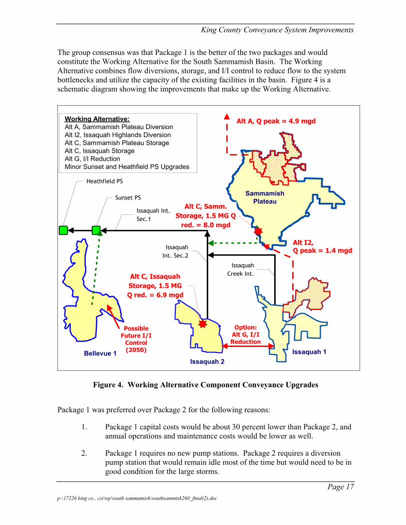
The group consensus was that Package 1 is the better of the two packages and would constitute the Working Alternative for the South Sammamish Basin. The Working Alternative combines flow diversions, storage, and I/I control to reduce flow to the system bottlenecks and utilize the capacity of the existing facilities in the basin. Figure 4 is a schematic diagram showing the improvements that make up the Working Alternative.
Sunset PS
Heathfield PS
Issaquah Int.Sec.1
IssaquahInt. Sec.2
IssaquahCreek Int.
Issaquah 1Issaquah 2
Bellevue 1
SammamishPlateau
Working Alternative:Alt A, Sammamish Plateau DiversionAlt I2, Issaquah Highlands DiversionAlt C, Sammamish Plateau StorageAlt C, Issaquah StorageAlt G, I/I ReductionMinor Sunset and Heathfield PS Upgrades
Alt I2,Q peak = 1.4 mgd
Alt A, Q peak = 4.9 mgd
Alt C, IssaquahStorage, 1.5 MGQ red. = 6.9 mgd
Alt C, Samm.Storage, 1.5 MG Q
red. = 8.0 mgd
Option:Alt G, I/IReduction
PossibleFuture I/I
Control(2050)
Figure 4. Working Alternative Component Conveyance Upgrades
Package 1 was preferred over Package 2 for the following reasons:
1. Package 1 capital costs would be about 30 percent lower than Package 2, and annual operations and maintenance costs would be lower as well.
2. Package 1 requires no new pump stations. Package 2 requires a diversion pump station that would remain idle most of the time but would need to be in good condition for the large storms.
Page 17 p:\17226 king co., csi\wp\south sammamish\southsammtsk260_final(2).doc

King County Conveyance System Improvements
3. Permitting for Package 1 would be easier because it does not involve the I-90 right-of-way.
While the group agreed the CSI project team should proceed with refining the Working Alternative, group members also raised specific issues concerning the Working Alternative and made recommendations for further analysis by the project team. Issues raised included:
1. Given the uncertainty associated with future growth forecasts and I/I projections, how would Package 1 be impacted if the future flows in the basin were higher/lower than forecasted in Task 240?
2. The operation and maintenance assumptions for storage systems and other conveyance facilities should be brought consistent with County practices, and the CSI team’s assumptions should be based on existing inspection, operation and maintenance cost data provided by the County.
3. Could the sewer that would divert wastewater northward from the Sammamish Plateau be eliminated by constructing more storage facilities in Issaquah and the Sammamish Plateau?
After the Decision Workshop, the CSI project team began gathering more information and refining the Working Alternative. In addition, the CSI project team addressed the specific questions raised in the Decision Workshop.
Refining the Working Alternative
The Working Alternative focuses on reducing the peak flow in the Issaquah Interceptor Section 1 (lake line) and downstream facilities. The reduction in peak flow is accomplished through a combination of flow diversion, peak flow storage, and I/I control. In addition, the Working Alternative was amended to include minor improvements to the Sunset and Heathfield Pump Stations to increase the maximum pumping capacity to 21 million gallons per day (mgd) at each station.
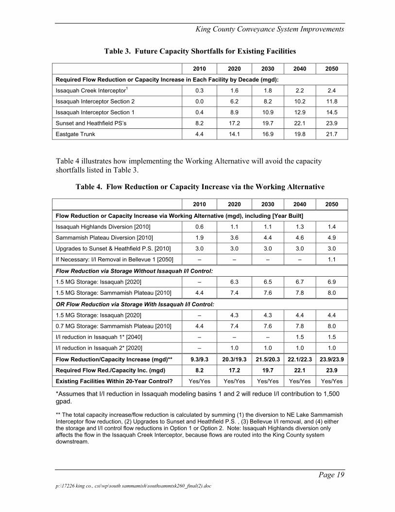
The Working Alternative would be implemented in a phased approach, so facilities are added or upgraded in time meet the basins’ peak 20-year flow but not before hand and so facility sizes can be adjusted as flow projections are updated. Phasing the improvements allows for more capital budget flexibility and also allows King County to assess and incorporate the Regional I/I program results. Table 3 quantifies the future capacity shortfalls by decade. Table 4 summarizes the timing of capacity additions and/or flow reductions making up the Working Alternative.
Page 18 p:\17226 king co., csi\wp\south sammamish\southsammtsk260_final(2).doc
King County Conveyance System Improvements
Table 3. Future Capacity Shortfalls for Existing Facilities
2010 2020 2030 2040 2050
Required Flow Reduction or Capacity Increase in Each Facility by Decade (mgd):
Issaquah Creek Interceptor1 0.3 1.6 1.8 2.2 2.4
Issaquah Interceptor Section 2 0.0 6.2 8.2 10.2 11.8
Issaquah Interceptor Section 1 0.4 8.9 10.9 12.9 14.5
Sunset and Heathfield PS’s 8.2 17.2 19.7 22.1 23.9
Eastgate Trunk 4.4 14.1 16.9 19.8 21.7
Table 4 illustrates how implementing the Working Alternative will avoid the capacity shortfalls listed in Table 3.
Table 4. Flow Reduction or Capacity Increase via the Working Alternative
2010 2020 2030 2040 2050
Flow Reduction or Capacity Increase via Working Alternative (mgd), including [Year Built]
Issaquah Highlands Diversion [2010] 0.6 1.1 1.1 1.3 1.4
Sammamish Plateau Diversion [2010] 1.9 3.6 4.4 4.6 4.9
Upgrades to Sunset & Heathfield P.S. [2010] 3.0 3.0 3.0 3.0 3.0
If Necessary: I/I Removal in Bellevue 1 [2050] – – – – 1.1
Flow Reduction via Storage Without Issaquah I/I Control:
1.5 MG Storage: Issaquah [2020] – 6.3 6.5 6.7 6.9
1.5 MG Storage: Sammamish Plateau [2010] 4.4 7.4 7.6 7.8 8.0
OR Flow Reduction via Storage With Issaquah I/I Control:
1.5 MG Storage: Issaquah [2020] – 4.3 4.3 4.4 4.4
0.7 MG Storage: Sammamish Plateau [2010] 4.4 7.4 7.6 7.8 8.0
I/I reduction in Issaquah 1* [2040] – – – 1.5 1.5
I/I reduction in Issaquah 2* [2020] – 1.0 1.0 1.0 1.0
Flow Reduction/Capacity Increase (mgd)** 9.3/9.3 20.3/19.3 21.5/20.3 22.1/22.3 23.9/23.9
Required Flow Red./Capacity Inc. (mgd) 8.2 17.2 19.7 22.1 23.9
Existing Facilities Within 20-Year Control? Yes/Yes Yes/Yes Yes/Yes Yes/Yes Yes/Yes
*Assumes that I/I reduction in Issaquah modeling basins 1 and 2 will reduce I/I contribution to 1,500 gpad.
** The total capacity increase/flow reduction is calculated by summing (1) the diversion to NE Lake Sammamish Interceptor flow reduction, (2) Upgrades to Sunset and Heathfield P.S. , (3) Bellevue I/I removal, and (4) either the storage and I/I control flow reductions in Option 1 or Option 2. Note: Issaquah Highlands diversion only affects the flow in the Issaquah Creek Interceptor, because flows are routed into the King County system downstream.
Page 19 p:\17226 king co., csi\wp\south sammamish\southsammtsk260_final(2).doc

King County Conveyance System Improvements
Implementation of the Working Alternative will bring all of the facilities in the South Sammamish Basin to King County’s peak 20-year conveyance standard throughout the planning period.
Analysis of Components of the Working Alternative
The following sections provide a more detailed analysis each of the major components of the Working Alternative.
Northward Diversion of Some Sammamish Plateau Flow
Diverting flow from the northern part of the Sammamish Plateau northward to the NE Lake Sammamish Interceptor would reduce demand in Section 1 of the Issaquah Interceptor. There is enough excess capacity in the NE Lake Sammamish Interceptor to accept flow from the northern part of the Sammamish Plateau and still accommodate the forecasted growth in its own drainage area.
Diversion Point for Northward Diversion
The CSI project team considered the need for conveying high flows and low flows when refining the route for the diversion from the northern part of the Sammamish Plateau to the NE Lake Sammamish Interceptor. Designing a pipeline to convey near-term, low flow at solids-carrying velocities (i.e., at 2 feet per second (fps)) and future peak flows without surcharge proved challenging because of the wide range of flow and the flat topography near Lake Sammamish. Future flows are projected to range from a 2010 base flow of 0.6 mgd to a 2050 peak 20-year flow of 4.9 mgd.
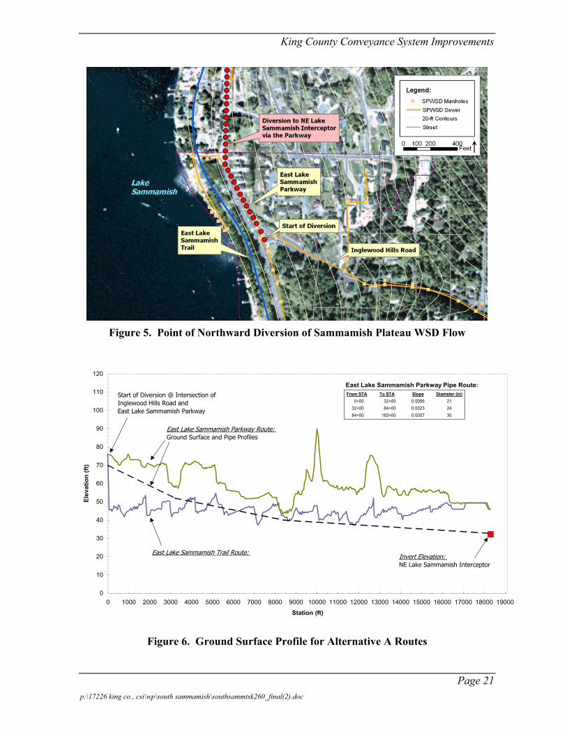
After examining three different diversion points, the CSI project team recommended a diversion starting at Inglewood Hills Road (see Figure 4). Starting from Inglewood Hills Road diverts more flow per capital dollar spent than the other two diversion points evaluated, and it does not require a pump station to send flow north.
Alternative Pipeline Alignments
When Alternative A was formulated in Task 240, the CSI project team focused on the alignment along East Lake Sammamish Parkway because it was not known if the East Lake Sammamish Trail would be developed and available to the County as an alignment. With the dismissal of a lawsuit that attempted to block construction of the trail, a trail alignment should be examined.
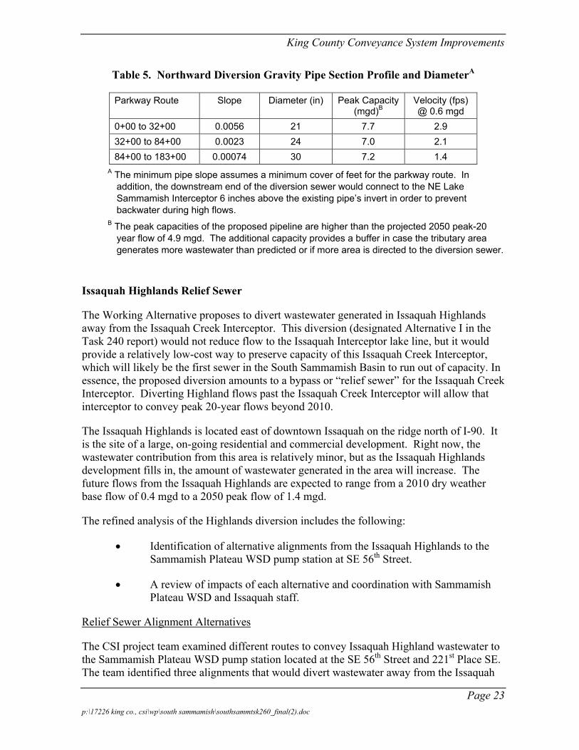
Figure 5 shows ground surface profiles of alignments along East Lake Sammamish Parkway and the East Lake Sammamish Trail, both developed with a digital elevation model (DEM) from U.S.G.S. map sources. The profiles clearly show the dramatic decrease in elevation as the alignment moves from roadway to the shoreline.
Page 20 p:\17226 king co., csi\wp\south sammamish\southsammtsk260_final(2).doc
King County Conveyance System Improvements
Figure 5. Point of Northward Diversion of Sammamish Plateau WSD Flow
0
10
20
30
40
50
60
70
80
90
100
110
120
0 1000 2000 3000 4000 5000 6000 7000 8000 9000 10000 11000 12000 13000 14000 15000 16000 17000 18000 19000
Station (ft)
Elev
atio
n (ft
)
Start of Diversion @ Intersection ofInglewood Hills Road and East Lake Sammamish Parkway
East Lake Sammamish Parkway Route: Ground Surface and Pipe Profiles
East Lake Sammamish Trail Route: Invert Elevation: NE Lake Sammamish Interceptor
East Lake Sammamish Parkway Pipe Route: From STA To STA Slope Diameter (in)
0+00 32+00 0.0056 21 32+00 84+00 0.0023 24 84+00 183+00 0.0007 30
Figure 6. Ground Surface Profile for Alternative A Routes
Page 21 p:\17226 king co., csi\wp\south sammamish\southsammtsk260_final(2).doc

King County Conveyance System Improvements
The area near Lake Sammamish, where most of the trail and parkway routes are located, is mostly flat, and the grade that is available for a gravity sewer is limited. The East Lake Sammamish Trail route has little, if any, drop over the final 18,000 lineal feet. The East Lake Sammamish Parkway route drops only 25 feet over 18,000 feet and has intermediate high spots. Gravity flow along the parkway route could be maintained by running a tight-line sewer for most of the route, allowing surcharging during large storms or by running a larger diameter pipe to maintain open channel flow at peak flows. It appears that a gravity pipeline of either type along the full length of the trail route may not be feasible, but a final determination cannot be made from the available planning data. While the parkway route is more hydraulically workable than the trail route, the predesign team should study the trail route further, because the route would have advantages over the parkway alignment. Specifically, the trail route alleviates several serious construction challenges that would be faced constructing a pipeline along East Lake Sammamish Parkway. The trail route reduces the level of effort for traffic control, mitigating impacts to sensitive areas, avoiding or moving existing utilities, and other constraints. As a result, the trail route should entail a lower construction costs and fewer impacts to the public during construction than East Lake Sammamish Parkway alignment. However, the lack of grade differential along the trail route would likely preclude a full-length gravity pipeline.
Pipe Diameter and Flow Velocity Range
The predesign team should give careful attention to the flow velocities, particularly in the near-term while the northern part of the Sammamish Plateau has large, undeveloped pockets. In the Task 240 report, the projected average dry weather flow will be about 0.6 mgd in 2010. At such a low flow rate through a pipe with a mostly flat profile, maintaining velocities greater than 2 fps at low flow may not be feasible. However, a velocity of 2 fps at full pipe flow is possible.
Table 5 lists the required pipe diameter needed for a gravity sewer along a NE Lake Sammamish Parkway alignment, given the available slope for the parkway. Given limited grade and low velocities, the County should consider open-channel flow so the inspection and maintenance group can access and clean the sewer if necessary. The pipe profiles assume a minimum cover of 4 feet for the parkway route, and the downstream connection would be 6 inches above the invert at the beginning of the NE Sammamish Interceptor
While some kind of pipeline along either of the proposed routes is technically feasible, selection of the trail route would likely require a pump station to move the flows. However, a hybrid route, following the parkway along the upper sections of pipeline and then moving along the trail for the lower sections may be also feasible. The predesign team should also conduct additional field work to determine if a modification to the trail route could produce increases slope in the pipeline. As this project moves forward, City of Sammamish officials should be consulted to see if there are any additional construction opportunities along East Lake Sammamish Parkway, as the City has preliminary plans for widening the East Lake Sammamish Parkway.
Page 22 p:\17226 king co., csi\wp\south sammamish\southsammtsk260_final(2).doc
King County Conveyance System Improvements
Table 5. Northward Diversion Gravity Pipe Section Profile and DiameterA
Parkway Route Slope Diameter (in) Peak Capacity (mgd)B
Velocity (fps) @ 0.6 mgd
0+00 to 32+00 0.0056 21 7.7 2.9 32+00 to 84+00 0.0023 24 7.0 2.1 84+00 to 183+00 0.00074 30 7.2 1.4
A The minimum pipe slope assumes a minimum cover of feet for the parkway route. In addition, the downstream end of the diversion sewer would connect to the NE Lake Sammamish Interceptor 6 inches above the existing pipe’s invert in order to prevent backwater during high flows.
B The peak capacities of the proposed pipeline are higher than the projected 2050 peak-20 year flow of 4.9 mgd. The additional capacity provides a buffer in case the tributary area generates more wastewater than predicted or if more area is directed to the diversion sewer.
Issaquah Highlands Relief Sewer
The Working Alternative proposes to divert wastewater generated in Issaquah Highlands away from the Issaquah Creek Interceptor. This diversion (designated Alternative I in the Task 240 report) would not reduce flow to the Issaquah Interceptor lake line, but it would provide a relatively low-cost way to preserve capacity of this Issaquah Creek Interceptor, which will likely be the first sewer in the South Sammamish Basin to run out of capacity. In essence, the proposed diversion amounts to a bypass or “relief sewer” for the Issaquah Creek Interceptor. Diverting Highland flows past the Issaquah Creek Interceptor will allow that interceptor to convey peak 20-year flows beyond 2010.
The Issaquah Highlands is located east of downtown Issaquah on the ridge north of I-90. It is the site of a large, on-going residential and commercial development. Right now, the wastewater contribution from this area is relatively minor, but as the Issaquah Highlands development fills in, the amount of wastewater generated in the area will increase. The future flows from the Issaquah Highlands are expected to range from a 2010 dry weather base flow of 0.4 mgd to a 2050 peak flow of 1.4 mgd.
The refined analysis of the Highlands diversion includes the following:
• Identification of alternative alignments from the Issaquah Highlands to the Sammamish Plateau WSD pump station at SE 56th Street.
• A review of impacts of each alternative and coordination with Sammamish Plateau WSD and Issaquah staff.
Relief Sewer Alignment Alternatives
The CSI project team examined different routes to convey Issaquah Highland wastewater to the Sammamish Plateau WSD pump station located at the SE 56th Street and 221st Place SE. The team identified three alignments that would divert wastewater away from the Issaquah
Page 23 p:\17226 king co., csi\wp\south sammamish\southsammtsk260_final(2).doc
King County Conveyance System Improvements
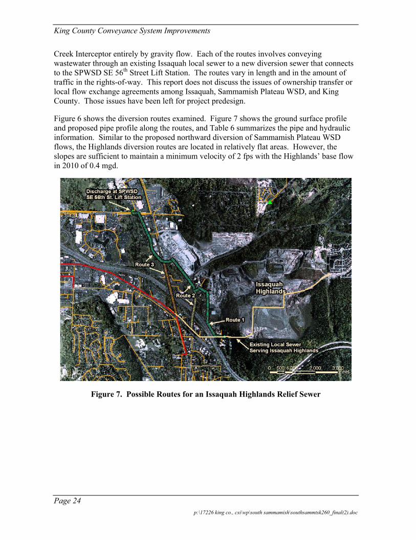
Creek Interceptor entirely by gravity flow. Each of the routes involves conveying wastewater through an existing Issaquah local sewer to a new diversion sewer that connects to the SPWSD SE 56th Street Lift Station. The routes vary in length and in the amount of traffic in the rights-of-way. This report does not discuss the issues of ownership transfer or local flow exchange agreements among Issaquah, Sammamish Plateau WSD, and King County. Those issues have been left for project predesign.
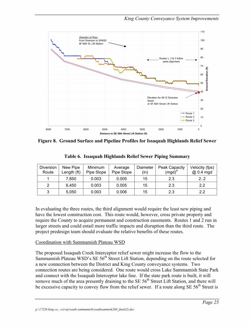
Figure 6 shows the diversion routes examined. Figure 7 shows the ground surface profile and proposed pipe profile along the routes, and Table 6 summarizes the pipe and hydraulic information. Similar to the proposed northward diversion of Sammamish Plateau WSD flows, the Highlands diversion routes are located in relatively flat areas. However, the slopes are sufficient to maintain a minimum velocity of 2 fps with the Highlands’ base flow in 2010 of 0.4 mgd.
Figure 7. Possible Routes for an Issaquah Highlands Relief Sewer
Page 24 p:\17226 king co., csi\wp\south sammamish\southsammtsk260_final(2).doc
King County Conveyance System Improvements
0
10
20
30
40
50
60
70
80
90
100
110
010002000300040005000600070008000
Distance to SE 56th Street Lift Station (ft)
Gro
und
Elev
atio
n (ft
)
Route 1Route 2Route 3
Elevation for Alt I2 Diversion Sewer at SE 56th Street Lift Station
Direction of Flow: From Diversion to SPWSDSE 56th St. Lift Station
Routes 1, 2 & 3 followsame alignment
Figure 8. Ground Surface and Pipeline Profiles for Issaquah Highlands Relief Sewer
Table 6. Issaquah Highlands Relief Sewer Piping Summary
Diversion Route
New Pipe Length (ft)
Minimum Pipe Slope
Average Pipe Slope
Diameter (in)
Peak Capacity (mgd)A
Velocity (fps) @ 0.4 mgd
1 7,850 0.003 0.005 15 2.3 2..2 2 6,450 0.003 0.005 15 2.3 2.2 3 5,050 0.003 0.006 15 2.3 2.2
In evaluating the three routes, the third alignment would require the least new piping and have the lowest construction cost. This route would, however, cross private property and require the County to acquire permanent and construction easements. Routes 1 and 2 run in larger streets and could entail more traffic impacts and disruption than the third route. The project predesign team should evaluate the relative benefits of these routes.
Coordination with Sammamish Plateau WSD
The proposed Issaquah Creek Interceptor relief sewer might increase the flow to the Sammamish Plateau WSD’s SE 56th Street Lift Station, depending on the route selected for a new connection between the District and King County conveyance systems. Two connection routes are being considered. One route would cross Lake Sammamish State Park and connect with the Issaquah Interceptor lake line. If the state park route is built, it will remove much of the area presently draining to the SE 56th Street Lift Station, and there will be excessive capacity to convey flow from the relief sewer. If a route along SE 56th Street is
Page 25 p:\17226 king co., csi\wp\south sammamish\southsammtsk260_final(2).doc
King County Conveyance System Improvements
selected, the SE 56th Street Lift Station will have to be rebuilt, and its capacity can be increased to accommodate the Issaquah Highlands flow.
Peak Flow Storage in Issaquah and Sammamish Plateau
The CSI project team conducted a field visit to Issaquah and Sammamish Plateau to evaluate the potential for siting storage systems in these areas. When evaluating storage areas, the team tried to eliminate areas with high groundwater that could affect construction or operation of a tank and looked for areas where the elevation was suitable for facility filling and draining by gravity.
Two storage configurations could be designed for simple operation, minimal maintenance (self-cleaning), and minimal impact (odor control) on surrounding land uses. The two configurations–cast-in-place, concrete tanks and tunneled conduits–differ primarily in their construction techniques. The selection of configuration will depend on site constraints and overall costs.
Near downtown Issaquah, there are several locations for building storage tanks and staging areas for building a tunnel. The CSI project team found few suitable locations in the lower portion of the Sammamish Plateau WSD service area for peak flow storage. One possible site is the District’s control structure property located on SE 43rd Way, on the hillside above East Lake Sammamish Parkway. A storage facility capable of storing 1 million gallons (MG) could be constructed on that site if the storage unit is 35 feet deep. If the facility spans onto adjacent undeveloped property, the total storage can be increased. Because the site is on a hillside, the design could incorporate self-cleaning features that would greatly reduce maintenance requirements.
Minor Upgrades to the Sunset PS and Heathfield PS
In discussion with King County staff, the CSI project team learned the Sunset and Heathfield Pump Stations maximum pumping capacity is currently estimated to be 18 mgd. The CSI project team noted that increasing the capacity a small amount, to about 21 mgd, would allow the station to convey the peak 20-year flow once the Working Alternative is implemented. At the February Decision Workshop, King County staff indicated the peak capacity could be increased through minor upgrades.
Responding to Workshop Issues
At the Decision Workshop in February 2002, three key issues were raised that required further investigation and analysis consideration by the CSI project team. The results of the project teams analysis are described below.
Page 26 p:\17226 king co., csi\wp\south sammamish\southsammtsk260_final(2).doc
King County Conveyance System Improvements
Impacts of Peak Wastewater Flow that Vary from Current Projections
The Working Alternative describes a plan for staging conveyance improvements over two decades. The timing and the sizing of conveyance upgrades is linked to the County’s wet weather peak flow projections. These projections are themselves based on model calibration to collected flow data, assumptions about future I/I rates, assumptions about sewer degradation, and growth forecasts. By continuing to monitor flows and refining the flow and sewered population projections, the County will be able to reduce the uncertainty about the timing and size of future conveyance facilities.
The alternative packages presented at the South Sammamish Basin Decision Workshop attempted to balance the short-term need for increased conveyance capacity and the long-term uncertainty regarding population growth and peak wet weather flow. In developing the alternative packages, one goal was a solution that would remain viable if future flows are different from the projections. The facility upgrades early in the program will be necessary and are appropriately sized, even if future flows are higher or lower than projected. The size of the facilities constructed later in the program can be adjusted to meet future demand. In response to workshop comments, the project team conducted a sensitivity analysis to determine whether the Working Alternative could me adapted to population and flow scenarios that differ from those used in Task 240.
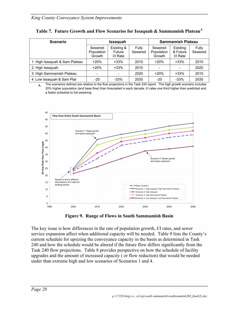
Most of the uncertainty in the future flow predictions derives from the amount of unsewered land in Issaquah and the Sammamish Plateau. The future “to-be-sewered” areas generate uncertainty over when the sewers will come online and how much I/I will these new systems admit. Four scenarios were developed to gauge the impact of development on future wet weather flows and the South Sammamish Basin Working Alternative (Table 7). The scenarios each represent higher or lower growth and I/I generation rates, and together they represent the likely range of future development and flow conditions in the upstream portions of the South Sammamish Basin.
Figures 9 shows how projected basin flows vary with variations in the rate of future growth. Through a combination of rapid growth, sewer expansion, and higher I/I rates, Scenario 1 predicts as much as 13 mgd more than the Task 240 flow projections in 20101 for the peak 20-year flow. Scenario 4, which reflects reduced and delayed development, predicts as much as 10 mgd less than the baseline flow projection for the peak 20-year flow in 2020.
1 The Task 240 projections were based on PSRC population forecasts and are considered the “base condition” in Figure 9.
Page 27 p:\17226 king co., csi\wp\south sammamish\southsammtsk260_final(2).doc
King County Conveyance System Improvements
Table 7. Future Growth and Flow Scenarios for Issaquah & Sammamish PlateauA
Scenario Issaquah Sammamish Plateau Sewered
Population Growth
Existing & Future I/I Rate
Fully Sewered
Sewered Population
Growth
Existing & Future I/I Rate
Fully Sewered
1. High Issaquah & Sam Plateau +20% +33% 2010 +20% +33% 2010 2. High Issaquah +20% +33% 2010 - - 2020 3. High Sammamish Plateau - - 2020 +20% +33% 2010 4. Low Issaquah & Sam Plat -20 -33% 2030 -20 -33% 2030
A. The scenarios defined are relative to the flow projections in the Task 240 report. The high growth scenario includes 20% higher population (and base flow) than forecasted in each decade, I/I rates one third higher than predicted and a faster schedule to full sewering.
0
5
10
15
20
25
30
35
40
45
50
55
60
65
1990 2000 2010 2020 2030 2040 2050
20-Y
ear P
eak
Hou
r Flo
w (m
gd)
Base Condition
Scenario 1: High Issaquah; High Sammamish Plateau
Scenario 2: High Issaquah
Scenario 3: High Sammamish Plateau
Scenario 4: Low Issaquah; Low Sammamish Plateau
Flow from Entire South Sammamish Basin
Spread is due to different assumptions of I/I rates for existing sewers
Scenario 1: Rapid growth and sewer expansion
Scenario 4: Slower growth and sewer expansion
Figure 9. Range of Flows in South Sammamish Basin
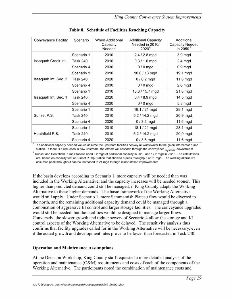
The key issue is how differences in the rate of population growth, I/I rates, and sewer service expansion affect when additional capacity will be needed. Table 9 lists the County’s current schedule for upsizing the conveyance capacity in the basin as determined in Task 240 and how the schedule would be altered if the future flow differs significantly from the Task 240 flow projections. Table 8 provides perspective on how the schedule of facility upgrades and the amount of increased capacity ( or flow reduction) that would be needed under than extreme high and low scenarios of Scenarios 1 and 4.
Page 28 p:\17226 king co., csi\wp\south sammamish\southsammtsk260_final(2).doc
King County Conveyance System Improvements
Table 8. Schedule of Facilities Reaching Capacity
Conveyance Facility Scenario When Additional Capacity Needed
Additional Capacity Needed in 2010/
2020A
Additional Capacity Needed
in 2050 A Scenario 1 2010 2.4 / 2.8 mgd 3.9 mgd Task 240 2010 0.3 / 1.6 mgd 2.4 mgd Issaquah Creek Int. Scenario 4 2030 0 / 0 mgd 0.9 mgd Scenario 1 2010 10.6 / 13 mgd 19.1 mgd Task 240 2020 0 / 6.2 mgd 11.8 mgd Issaquah Int. Sec. 2 Scenario 4 2030 0 / 0 mgd 2.6 mgd Scenario 1 2010 13.3 / 15.7 mgd 21.8 mgd Task 240 2020 0.4 / 8.9 mgd 14.5 mgd Issaquah Int. Sec. 1 Scenario 4 2030 0 / 0 mgd 5.3 mgd Scenario 1 2010 18.1 / 21 mgd 28.1 mgd Task 240 2010 5.2 / 14.2 mgd 20.9 mgd Sunset P.S. Scenario 4 2020 0 / 3.6 mgd 11.6 mgd Scenario 1 2010 18.1 / 21 mgd 28.1 mgd Task 240 2010 5.2 / 14.2 mgd 20.9 mgd Heathfield P.S. Scenario 4 2020 0 / 3.6 mgd 11.6 mgd
A The additional capacity needed values assume the upstream facilities convey all wastewater to the given interceptor pump station. If there is a reduction in flow upstream, the effects will cascade through the conveyance system. downstream
B Sunset and Heathfield Pump Stations need 8.2 mgd of additional capacity in 2010 and 17.2 mgd in 2020. The calculations are based on capacity test at Sunset Pump Station that showed a peak throughput of 21 mgd. The working alternative assumes peak throughput can be increased to 21 mgd through minor station improvements.
If the basin develops according to Scenario 1, more capacity will be needed than was included in the Working Alternative, and the capacity increases will be needed sooner. This higher than predicted demand could still be managed, if King County adapts the Working Alternative to these higher demands. The basic framework of the Working Alternative would still apply. Under Scenario 1, more Sammamish Plateau flow would be diverted to the north, and the remaining additional capacity demand could be managed through a combination of aggressive I/I control and larger storage facilities. The conveyance upgrades would still be needed, but the facilities would be designed to manage larger flows. Conversely, the slower growth and tighter sewers of Scenario 4 allow the storage and I/I control aspects of the Working Alternative to be delayed. The sensitivity analysis thus confirms that facility upgrades called for in the Working Alternative will be necessary, even if the actual growth and development rates prove to be lower than forecasted in Task 240.
Operation and Maintenance Assumptions
At the Decision Workshop, King County staff requested a more detailed analysis of the operation and maintenance (O&M) requirements and costs of each of the components of the Working Alternative. The participants noted the combination of maintenance costs and
Page 29 p:\17226 king co., csi\wp\south sammamish\southsammtsk260_final(2).doc

King County Conveyance System Improvements
staffing requirements could be a determining factor in the selection of proposed wastewater facilities.
The County has years of pipeline maintenance cost data on which to base O&M cost estimates for pipelines, but County has less experience with storage facilities. The annual pipe maintenance costs ($1 per foot per year) are based on the 2000 budget report from the County’s Sewer Inspection, Cleaning, and Repair Program. Storage facility O&M requirements were discussed with King County staff, and the storage facility O&M cost estimates are based on those discussions and on O&M costs for storage facilities as estimated in the Combined Sewer Overflow Control Project 1995 Update (1995 CSO Update).
For the operation and maintenance cost estimates, the CSI project team assumed storage facilities could be designed for simple operation, minimal maintenance (self-cleaning). Table 9 summarizes the inputs used to generate the O&M cost estimate for a hypothetical 1.5 MG tunnel and 26,000-foot long pipeline. In this example, it is assumed that the storage tunnel will be used once per year.
Table 9. Storage Facility O&M Cost Estimate Inputs
O&M Cost Component Annual CostA 1.5 MG Storage Tunnel (used once per year)
Off-Line Storage Pipes Maintenance Cost $2,300 per year Off-Line Storage Pipes Inspection Cost $800 per year
Total Storage O&M Cost: $3,100 per year Gravity Sewer:
Inspection, Cleaning, Repair $1 per ft per yr Total Gravity Sewer O&M Cost: $26,000 per year Total O&M for Working Alternative $32,200 per year
A. Note that bold values are changed from the 1995 CSO Update spreadsheet; all other values are unchanged.
Possibility of Increasing Storage to Eliminate the Northern Diversion
During the Decision Workshop, King County staff asked if the diversion of Sammamish Plateau flows to the NE Lake Sammamish Interceptor could be avoided by adding larger amounts of storage in the Sammamish Plateau WSD service area. The northward diversion cannot be eliminated by increased storage for the following reasons:
1. The Sammamish Plateau WSD system has a relatively small amount of I/I. This generates a rainfall-runoff response in the area characterized by wider hydrographs rather than narrow, high-peaked hydrographs typical for areas with direct inflow connections. In other words, a tighter system generally has a higher total-volume-to-peak-flow ratio than a leaky system. Thus, reducing the peak flow by a given percentage in a relatively tight system requires more
Page 30 p:\17226 king co., csi\wp\south sammamish\southsammtsk260_final(2).doc
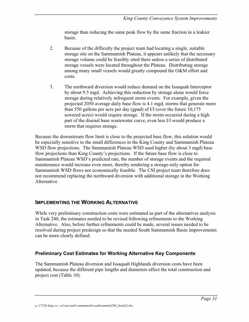
King County Conveyance System Improvements
storage than reducing the same peak flow by the same fraction in a leakier basin.
2. Because of the difficulty the project team had locating a single, suitable storage site on the Sammamish Plateau, it appears unlikely that the necessary storage volume could be feasibly sited there unless a series of distributed storage vessels were located throughout the Plateau. Distributing storage among many small vessels would greatly compound the O&M effort and costs.
3. The northward diversion would reduce demand on the Issaquah Interceptor by about 9.5 mgd. Achieving this reduction by storage alone would force storage during relatively infrequent storm events. For example, given the projected 2050 average daily base flow is 4.1 mgd, storms that generate more than 550 gallons per acre per day (gpad) of I/I (over the future 10,175 sewered acres) would require storage. If the storm occurred during a high part of the diurnal base wastewater curve, even less I/I would produce a storm that requires storage.
Because the downstream flow limit is close to the projected base flow, this solution would be especially sensitive to the small differences in the King County and Sammamish Plateau WSD flow projections. The Sammamish Plateau WSD used higher (by about 3 mgd) base flow projections than King County’s projections. If the future base flow is close to Sammamish Plateau WSD’s predicted rate, the number of storage events and the required maintenance would increase even more, thereby rendering a storage-only option for Sammamish WSD flows not economically feasible. The CSI project team therefore does not recommend replacing the northward diversion with additional storage in the Working Alternative.
IMPLEMENTING THE WORKING ALTERNATIVE
While very preliminary construction costs were estimated as part of the alternatives analysis in Task 240, the estimates needed to be revised following refinements to the Working Alternative. Also, before further refinements could be made, several issues needed to be resolved during project predesign so that the needed South Sammamish Basin improvements can be more clearly defined.
Preliminary Cost Estimates for Working Alternative Key Components
The Sammamish Plateau diversion and Issaquah Highlands diversion costs have been updated, because the different pipe lengths and diameters affect the total construction and project cost (Table 10).
Page 31 p:\17226 king co., csi\wp\south sammamish\southsammtsk260_final(2).doc
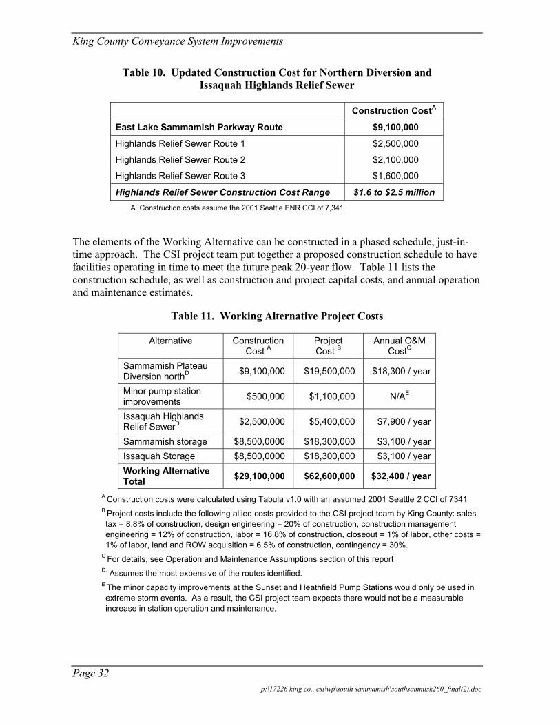
King County Conveyance System Improvements
Table 10. Updated Construction Cost for Northern Diversion and Issaquah Highlands Relief Sewer
Construction CostA
East Lake Sammamish Parkway Route $9,100,000
Highlands Relief Sewer Route 1 $2,500,000
Highlands Relief Sewer Route 2 $2,100,000
Highlands Relief Sewer Route 3 $1,600,000
Highlands Relief Sewer Construction Cost Range $1.6 to $2.5 million A. Construction costs assume the 2001 Seattle ENR CCI of 7,341.
The elements of the Working Alternative can be constructed in a phased schedule, just-in-time approach. The CSI project team put together a proposed construction schedule to have facilities operating in time to meet the future peak 20-year flow. Table 11 lists the construction schedule, as well as construction and project capital costs, and annual operation and maintenance estimates.
Table 11. Working Alternative Project Costs
Alternative Construction Cost A
Project Cost B
Annual O&M CostC
Sammamish Plateau Diversion northD $9,100,000 $19,500,000 $18,300 / year
Minor pump station improvements $500,000 $1,100,000 N/AE
Issaquah Highlands Relief SewerD $2,500,000 $5,400,000 $7,900 / year
Sammamish storage $8,500,0000 $18,300,000 $3,100 / year Issaquah Storage $8,500,0000 $18,300,000 $3,100 / year Working Alternative Total $29,100,000 $62,600,000 $32,400 / year
A Construction costs were calculated using Tabula v1.0 with an assumed 2001 Seattle 2 CCI of 7341 B Project costs include the following allied costs provided to the CSI project team by King County: sales tax = 8.8% of construction, design engineering = 20% of construction, construction management engineering = 12% of construction, labor = 16.8% of construction, closeout = 1% of labor, other costs = 1% of labor, land and ROW acquisition = 6.5% of construction, contingency = 30%.
C For details, see Operation and Maintenance Assumptions section of this report D. Assumes the most expensive of the routes identified. E The minor capacity improvements at the Sunset and Heathfield Pump Stations would only be used in extreme storm events. As a result, the CSI project team expects there would not be a measurable increase in station operation and maintenance.
Page 32 p:\17226 king co., csi\wp\south sammamish\southsammtsk260_final(2).doc
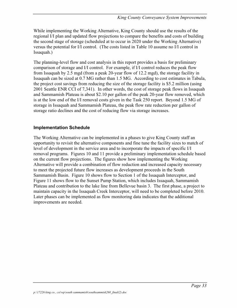
King County Conveyance System Improvements
While implementing the Working Alternative, King County should use the results of the regional I/I plan and updated flow projections to compare the benefits and costs of building the second stage of storage (scheduled at to occur in 2020 under the Working Alternative) versus the potential for I/I control. (The costs listed in Table 10 assume no I/I control in Issaquah.)
The planning-level flow and cost analysis in this report provides a basis for preliminary comparison of storage and I/I control. For example, if I/I control reduces the peak flow from Issaquah by 2.5 mgd (from a peak 20-year flow of 12.2 mgd), the storage facility in Issaquah can be sized at 0.7 MG rather than 1.5 MG. According to cost estimates in Tabula, the project cost savings from reducing the size of the storage facility is $5.2 million (using 2001 Seattle ENR CCI of 7,341). In other words, the cost of storage peak flows in Issaquah and Sammamish Plateau is about $2.10 per gallon of the peak 20-year flow removed, which is at the low end of the I/I removal costs given in the Task 250 report. Beyond 1.5 MG of storage in Issaquah and Sammamish Plateau, the peak flow rate reduction per gallon of storage ratio declines and the cost of reducing flow via storage increases.
Implementation Schedule
The Working Alternative can be implemented in a phases to give King County staff an opportunity to revisit the alternative components and fine tune the facility sizes to match of level of development in the service area and to incorporate the impacts of specific I/I removal programs. Figures 10 and 11 provide a preliminary implementation schedule based on the current flow projections. The figures show how implementing the Working Alternative will provide a combination of flow reduction and increased capacity necessary to meet the projected future flow increases as development proceeds in the South Sammamish Basin. Figure 10 shows flow to Section 1 of the Issaquah Interceptor, and Figure 11 shows flow to the Sunset Pump Station, which includes Issaquah, Sammamish Plateau and contribution to the lake line from Bellevue basin 3. The first phase, a project to maintain capacity in the Issaquah Creek Interceptor, will need to be completed before 2010. Later phases can be implemented as flow monitoring data indicates that the additional improvements are needed.
Page 33 p:\17226 king co., csi\wp\south sammamish\southsammtsk260_final(2).doc
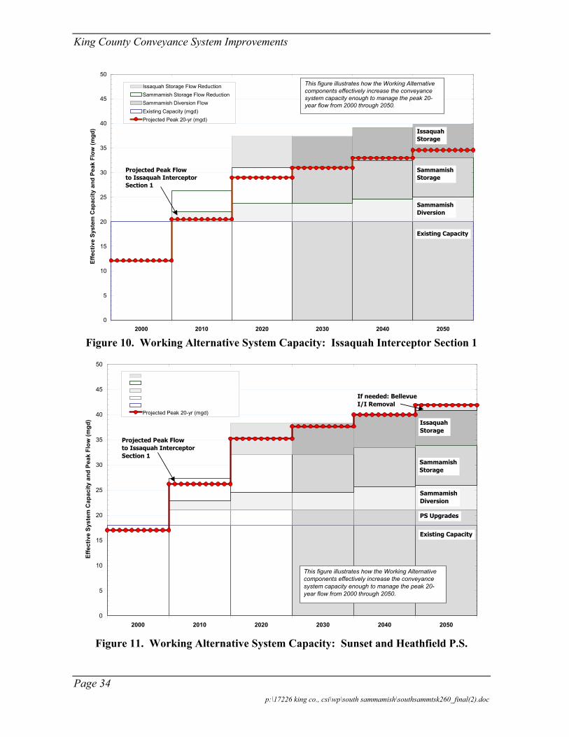
King County Conveyance System Improvements
0
5
10
15
20
25
30
35
40
45
50
2000 2010 2020 2030 2040 2050
Effe
ctiv
e Sy
stem
Cap
acity
and
Pea
k Fl
ow (m
gd)
Projected Peak 20-yr (mgd)
Existing Capacity
Sammamish Diversion
Sammamish Storage
Issaquah Storage
Projected Peak Flow to Issaquah Interceptor Section 1
This figure illustrates how the Working Alternative components effectively increase the conveyance system capacity enough to manage the peak 20-year flow from 2000 through 2050.
Issaquah Storage Flow ReductionSammamish Storage Flow ReductionSammamish Diversion FlowExisting Capacity (mgd)
Issaquah Storage Flow ReductionSammamish Storage Flow ReductionSammamish Diversion FlowMinor Pump Station UpgradesExisting Capacity (mgd)
Figure 10. Working Alternative System Capacity: Issaquah Interceptor Section 1
0
5
10
15
20
25
30
35
40
45
50
2000 2010 2020 2030 2040 2050
Effe
ctiv
e Sy
stem
Cap
acity
and
Pea
k Fl
ow (m
gd)
Projected Peak 20-yr (mgd)
Existing Capacity
Sammamish Diversion
Sammamish Storage
Issaquah Storage
Projected Peak Flow to Issaquah Interceptor Section 1
This figure illustrates how the Working Alternative components effectively increase the conveyance system capacity enough to manage the peak 20-year flow from 2000 through 2050.
PS Upgrades
If needed: Bellevue I/I Removal
Figure 11. Working Alternative System Capacity: Sunset and Heathfield P.S.
Page 34 p:\17226 king co., csi\wp\south sammamish\southsammtsk260_final(2).doc
King County Conveyance System Improvements
Page 35 p:\17226 king co., csi\wp\south sammamish\southsammtsk260_final(2).doc
Issues for Predesign Team
While the components of the Working Alternative are described in enough detail to transfer to King County’s CIP group, the following will be required during project predesign:
1. Review the two alignments described here to transfer flow north from the Sammamish Plateau (Alternative A) and develop a final route
2. Examine the three routes proposed for the Highlands relief sewer and develop a final route. Also, coordinate with the Sammamish Plateau WSD as its comprehensive plan is adopted so the impacts of the Highlands relief sewer are mitigated.
3. Finalize the siting of the Issaquah storage facilities. Investigate whether all of the Sammamish Plateau storage can be sited at the SE 43rd Way Sammamish Plateau WSD control structure property.
4. Consult the environmental review of the Working Alternative (see Appendix F) for sensitive areas and permitting requirements.