kinematic design and commutation of a spherical stepper
TRANSCRIPT
342 IEEE/ASME TRANSACTIONS ON MECHATRONICS, VOL. 4, NO. 4, DECEMBER 1999
Kinematic Design and Commutationof a Spherical Stepper Motor
Gregory S. Chirikjian,Member, IEEE, and David Stein,Student Member, IEEE
Abstract—This paper addresses the design and commutation ofa novel kind of spherical stepper motor in which the poles of thestator are electromagnets and the poles of the rotor (rotating ball)are permanent magnets. Due to the fact that points on a spherecan only be arranged with equal spacing in a limited number ofcases (corresponding to the Platonic solids), design of sphericalstepper motors with fine rotational increments is fundamentallygeometrical in nature. We address this problem and the relatedproblem of how rotor and stator poles should be arranged inorder to interact to cause motion. The resulting design has a muchwider range of unhindered motion than other spherical steppermotor designs in the literature. We also address the problem ofcommutation, i.e., we determine the sequence of stator polaritiesin time that approximate a desired spherical motion.
Index Terms—Circle packing, rotation group, spherical motor.
I. INTRODUCTION
T HIS paper addresses the design and coordination of spher-ical motors with a large range of motion. Applications of
spherical motors are numerous. They include the following: 1)camera actuators for computer vision [1], as in Fig. 1(a); 2)robotic wrist, elbow, and shoulder actuators, as in Fig. 1(b)(allowing six or nine degrees of freedom to be designedcompactly into a small space); 3) omnidirectional wheels formobile robots, as in Fig. 1(c); and 4) actuator arrays capableof transporting objects in any direction [2], [3], as in Fig. 1(d).
Of course, the concept of a spherical motor is not new. Ourwork builds on the accomplishments of a number of notableworks. The basic operating principles of spherical dc inductionmotors have been known for quite some time, see, e.g., [4]and [5]. Kanekoet al. [6] developed a spherical dc servomotor. The design and implementation of spherical variable-reluctance motors has been studied by Leeet al. for a numberof years [7]–[10]. Toyamaet al. have developed sphericalultrasonic motors [11], [12]. In the literature, one even findsactuators with a full six degrees of freedom, e.g., [13]. A goodintroduction to the principles behind traditional permanent-magnet motors can be found in [14]. These principles are verymuch the same for the spherical case, although the geometricalaspects in the design are quite different.
In the following sections, we address kinematic issues inthe design and commutation of a new spherical stepper motor.
Manuscript received January 8, 1999; revised August 9, 1999. Recom-mended by Guest Editor B. Ravani. This work was supported by the NationalScience Foundation under Grant IIS-9731720 from the Robotics and HumanAugmentation Program.
The authors are with the Department of Mechanical Engineering, The JohnsHopkins University, Baltimore, MD 21218 USA.
Publisher Item Identifier S 1083-4435(99)09955-X.
In our design, the rotor poles are permanent magnets, andthe stator poles are electromagnets. The key issues addressedhere are how to arrange the stator and rotor poles so as toachieve relatively finely discretized motion. In contrast to theother spherical motor designs referenced above, we seek toplace more poles than the numbers dictated by the regular(Platonic) solids. To this end, Section II examines how rotorand stator poles can be placed “semiregularly” in a recursivefashion with a high degree of symmetry. Section III thenexamines how to commutate any of a variety of possiblemotor designs generated using the techniques of Section II.Section IV discusses the design and implementation of aparticular stepper motor and provides a detailed example ofa commutation sequence.
II. THE KINEMATIC DESIGN PROBLEM: ROTOR
AND STATOR POLE PLACEMENT
Central to the design of spherical motors is the selection ofcompatible rotor and stator geometries. In the same way thatstandard cylindrical motors must not have the same number ofrotor and stator poles in order to operate, the symmetries ofspherical rotors and stators must not be the same. The questionthen becomes one of finding which combination of stator androtor arrangements is the most appropriate. Since there is avery limited number of regular arrangements of points onthe sphere (there are only five corresponding to the Platonicsolids), and since these are far too coarsely distributed foruse in a discrete-state motor capable of the applications dis-cussed earlier, the question becomes one of finding compatible“semiregular” rotor and stator arrangements.
It has been known for thousands of years that only fiveconvex three-dimensional polyhedra exist which have polygo-nal faces that are both congruent and regular. These so-calledperfect solids are the tetrahedron (4 triangular faces), cube (6square faces), octahedron (8 triangular faces), dodecahedron(12 pentagonal faces), and icosahedron (20 triangular faces).By projecting faces of any of these polyhedra onto a spherefrom the common center of the sphere and polyhedron, thesphere is divided into regions of equal area and shape. Regularcircle packings on the sphere are generated by inscribingcircles in each of these regions (which is the same as firstinscribing circles in each polygonal face of a perfect solid andthen projecting onto the sphere).
The focus of this section is the generation of “semiregular”circle packings on the sphere. These are generated by observ-ing the duality of the perfect solids (i.e., connecting the centersof all adjacent faces of any perfect solid results in another
1083–4435/99$10.00 1999 IEEE

CHIRIKJIAN AND STEIN: SPHERICAL STEPPER MOTOR 343
(a) (b)
(c) (d)
Fig. 1. Applications of spherical motors.
perfect solid). In particular, the tetrahedron is dual to itself,the cube is dual to the octahedron, the dodecahedron is dual tothe icosahedron. A finite group of rotational symmetries existsfor each pair of dual perfect solids. By subdividing the sphereinto units formed by overlaying the projections of dual perfectsolids on the sphere, and observing the symmetries of theseunits, it is shown below how 16 packings of congruent circleson the sphere are generated in addition to the regular packings.It is then shown how one can pack an arbitrary numberof “almost congruent” circles on the sphere by recursivelysubdividing these units and inscribing circles in each resultingsubdivision. In either case, these semiregular packings ofcongruent circles inherit the symmetry group of their dualparent polyhedra.
Of the 21 regular and semiregular circle packings, twoare redundant. The remaining 19 circle packings possessthree desirable properties: 1) all circles “kiss” their nearestneighbors; 2) uncovered areas of the sphere surrounded by
congruent circles posses discrete rotational symmetry; and 3)uncovered areas surrounded by circles of different size arealways enclosed by exactly three circles. These properties formthe starting point for a recursion that allows one to pack anarbitrarily large number of incongruent circles on the sphere,the centers of each circle corresponding to the center of arotor pole. These packings allow one to achieve very highpacking ratios, and retain the tetrahedral, cubo–octahedral, oricosa–dodecahedral rotational symmetries of the base semireg-ular packings of congruent circles.
A. Mathematical Preliminaries
Positions on the unit sphere are parametrized usingspherical coordinates

344 IEEE/ASME TRANSACTIONS ON MECHATRONICS, VOL. 4, NO. 4, DECEMBER 1999
and are called the polar and azimuthal angles, respec-tively.1
The distance between two points as measuredalong the shorter segment of the great arc connecting the pointsis calculated as
(1)
where, in the context of the current discussion, takesvalues in the range In this way, the length of the shorterof the two great arcs connecting and is automaticallychosen.
For example, the distance between the north poleand any arbitrary point is
A regular placement of points on the unit sphere is onefor which the distance between each point and its nearestneighbors is the same for all points considered. It has beenwell known since the time of the ancient Greeks that theonly regular placements of points correspond to the verticesof the so-called Platonic solids: tetrahedron, octahedron, cube,icosahedron, and dodecahedron with 4, 6, 8, 12, and20, respectively. Fig. 2 shows the icosahedral and octahedraltessellations of the sphere.
As an interesting aside, we note that the simplest sphericallyshaped viruses encode just enough genetic information toexpress a single kind of protein unit. A number of theseunits then self-assemble to form a protein shell. These shellshave icosahedral symmetry because this is the regular packingwhich best approximates a sphere [16], [17]. More sophisti-cated viruses encode more than one kind of protein which selfassemble to form semiregular polyhedral shells. We also notethat a number of spherical circle packings in nature can befound in other contexts [18].
Since it is desirable to place rotor and stator poles at finerincrements than the vertices of the Platonic solids to achievefiner discretization of rotation, one must consider alternativesto these regular placements.
One approach is to consider the desirable number of statorand rotor poles and pack this number of same-sized circleson the sphere. The centers of these circles then indicatethe placement of the centers of the poles. In fact, a widevariety of packings have already been studied in the literaturein the context of several different applications (see, e.g.,[19]–[21]) An extensive list of spherical circle packings, withup to thousands of circles, is available on the Internet athttp://www.research.att.com/˜njas.
However, as a rule, such packings do not posses the degreeof symmetry that the regular packings do. This is quiteimportant in the context of a spherical stepper, where therotor and stator poles must have some compatibility in orderto be able commutate. Our approach is, therefore, to userecursive semiregularpackings of almost-equal-sized circleson the sphere. Our search will begin with the vertices of thePlatonic solids, and recursively place new points until thedesired number is approximated. Then, evaluations of howwell disbursed the points are, and how compatible the choice
1Often in the engineering literature, the meanings of the symbols� and� are reversed from our notation (see, e.g., [15]), whereas our notation isconsistent with the mathematics and physics literature.
(a)
(b)
Fig. 2. (a) Octahedral and (b) icosahedral discretization of the sphere.
for rotor and stator is, will be performed. In order to do this, wemust first develop some mathematical tools to do geometricalconstructions on the sphere. Fig. 3 is helpful in this regard.
The plane which intersects the sphere resulting in the greatcircle containing points and has a unit normal
The plane containing the great circle which, in turn, containsand is described by
where is the vector of Cartesian coordinates of anarbitrary point.
Given a point on the sphere, one can determine theshortest distance measured on the sphere betweenand thegreat circle defined by by first constructing a plane passingthrough the origin and the point which is orthogonal to the

CHIRIKJIAN AND STEIN: SPHERICAL STEPPER MOTOR 345
Fig. 3. Distance between a point and great arc.
plane defined by Since and must lie in this new plane,it is defined by the normal
The great arc defined by contains and intersects at a rightangle the great arc containingand This means the shortestdistance between and the great arc defined byis measuredalong the great arc defined by
The intersection of the two planes, written as the simulta-neous equations
define a line that intersects the sphere at the points
Thus, the distance betweenand the arc defined by is
where simply means minimization with respect to thechoice of
Observing that, for
and
one obtains the simple answer
We will use this simple result in the next section to inscribea spherical cap inside an arbitrary spherical triangle.
Fig. 4. Inscribing circles within existing geometric structures.
B. Recursive Generation of Circle Packings
To begin, the coordinates of the vertices of the Platonicsolids are required. These are calculated as follows, whereeach solid is centered at the origin, and the vertices all lie onthe surface of the unit sphere
Tetrahedron:The spherical coordinates of the first vertexcan be taken as (the north pole). Theremaining three vertices have spherical coordinates
and The polar angle is determinedby the equality
Octahedron: The vertices lie at
Cube: The vertices lie at
Icosahedron: It is clear from its symmetry thatThen, there are two sets
of five points with coordinates as follows. The first sethas coordinates and
The second set is rotated about theaxis byrelative to the first, and is as distant from the south
pole as the other set is from the north pole:and
The angle is determined by
or
Dodecahedron:The vertices are determined by taking allsets of three most proximal vertices of the icosahedron,adding them, and normalizing so that the result is a unitvector.
1) Inscribing Circles in Triangular Regions on the Sphere:Any three points define the vertices of a sphericaltriangle. Therefore, they define the spherical triangle. In thissection, we solve the following: given these points, find afourth point that is simultaneously equidistant from the threeedges of the spherical triangle and, hence, defines the centerof an inscribed circular cap (see Fig. 4).
This can be stated as the solution of the set ofequations
where and
346 IEEE/ASME TRANSACTIONS ON MECHATRONICS, VOL. 4, NO. 4, DECEMBER 1999
This problem can be restated as the three equations
Clearly, satisfies the first two equations when it is a scalarmultiple of the cross product of and The lastequation is satisfied by normalizing this result. Hence,
The two choices correspond to the same circle in butdifferent circular caps with antipodal centers and radiiand
That is, for every spherical circular cap, there is anotherwhich is its complement in the sphere. We choose the value of
for which the radius as measured on the sphere is smaller.Using this general result, one can inscribe circles in thespherical triangles that result from subdividing the sphericalpolygons generated by connecting the vertices listed in theprevious section.
2) Inscribing Spherical Circles in the Space Between Ex-isting Spherical Circles:Suppose one is given three kissingcircles on the surface of the sphere, with centers andradii and as measured on the surface of the sphere.Then, to find the center of a circle inscribed in the spacebetween the three circles, one solves the system of equations
(2)
for where is the unknown position of the center ofthe desired circle, and is its radius. This system of equationsis solvable in closed form as follows.
First, take the cosine of (2) for each value ofand expandthe right side using trigonometric rules. The result is writtenin matrix form as
(3)
where
and
Hence, once is known, can be found by a simple matrixinversion. is found by isolating in (3), and writing the dotproduct
Making the standard substitutions
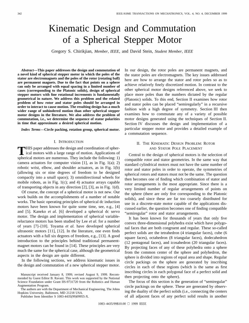
Fig. 5. Enumeration of semiregular circle packings.
and
the equation reduces to a quadratic equation inwith two roots for The smallest positive real root is thenchosen, and backsubstitution yields
The problem of finding the inscribed circle within fourtouching circles, the problem of inscribing a circle in a spher-ical quadrilateral with symmetry, and the problem of findingthe circle inscribed in the space between a spherical triangleand an already-existing inscribed circle follow similarly.
3) Enumeration of Semiregular Spherical Circle Packings:Once the sphere is tessellated into congruent regular sphericaltriangles, there are seven ways to inscribe circles within andbetween these triangles. These are depicted in Fig. 5. Using thetechniques outlined previously, and knowing the coordinatesof all the vertices, the positions of the centers of these circles(which we refer to asprimary circles) and their radii are easilycalculated.
Doing the enumeration explicitly, one finds that two setsof semiregular circle packings are shared between those withoctahedral and tetrahedral symmetry. Hence, the number ofdistinct semiregular packings is 19 (5 Platonic14 others).
These semiregular packings form the starting point for arecursive procedure in which circles can be inscribed withincollections of kissing circles to fill the remaining emptyspaces. Particularly promising semiregular packings are: 1)the one with icosahedral symmetry with six half circles pertriangle, and two other sized circles inscribed in the centerand at the vertices and 2) the one with octahedral symmetryand six primary circles inscribed per triangle, with smallerones inscribed around them. In this way, the primary circlesfrom both packings are almost the same size and, since thesymmetry groups of the packings are not the same, there willnever be a state from which the motor is unable to escape. Itwould seem that choosing any two of the 19 distinct packingsfrom different symmetry categories is a prerequisite for rotorand stator compatibility. It is also important that a sufficientnumber of rotor and stator poles line up to generate narrowpotential wells corresponding to stepper states. Our choicesatisfies this requirement as well.

CHIRIKJIAN AND STEIN: SPHERICAL STEPPER MOTOR 347
III. M ATHEMATICAL FORMULATIONS
OF THE COMMUTATION PROBLEM
In this section, the commutation problem is addressed.In the two subsequent sections, the problem is addressed
using two different perspectives. In Section III-A, a purelygeometrical approach based on spherical distances between thecenters of rotor and stator poles is examined. In Section III-B, a functional-analytic approach in which a simplified modelof the interference between rotor and stator magnetic fields isused to determine the best matching to implement a desiredmotion.
A. Geometric Approach
We discretize any given rotational trajectory intosegments corresponding to points The values
can be taken as the even discretization of time oras the solution generated from a motion interpolation proce-dure imposing the requirement that the “rotational distance”between adjacent rotations be equal for some measure ofdistance between rotations
Such interpolation procedures are described in [23]–[25] and[27] for a variety of different distance (metric) functions.
The distance function for rotations introduced to the me-chanical design community by Park [24] is particularly phys-ically meaningful and easy to calculate, as explained below.
A general rotation is written as
ROT
ROT
where is the skew symmetric matrix satisfyingfor all vect is the unit vector specifying theaxis of rotation, and is the angle of rotation. is the 3 3identity matrix. The rotations about the natural basis vectorsare denoted and is any rotation matrix whoseth column is the vector The functions [26]
and
vect
can be thought of as those which extract the angleand axisfrom the rotation matrix ROT Park’s metric is then
Regardless of how the values and, hence, the matricesare generated, the problem reduces at each value
of to find an optimal match between at least two statorand rotor poles that are attainable given the current actualorientation 2
2Fixing only two points on the surface of the sphere (which do not lie onthe same axis through its center) is required to fix the orientation of the spherewhose origin is already fixed.
Since the motor has discrete states, in general,but is minimal under the constraints of the motordesign and motion history dictated by the desired trajectory.
Given the set of stator poles and the set of rotorpoles one can sort the distances
for each desired rotation to find candidates for thematching that would best implement the desired rotation.In general, none of these matchings will yield the desiredrotation but rather a set of approximations for
The one matching that is chosen fromthis set is then denoted as In order to arrive at this choice,the list of candidates is reduced based on two criteria.
• All candidates for which the distanceare too large to achieve for the given
motor design are excluded.• Even if the transition from to is within the reach
of a single step, it is desirable to have the axis of therelative rotation point as much as possiblealong the direction of the axis of Hence, theremaining candidates are reduced to a single candidateby finding the one which minimizes the cost function
If the motor is properly designed, at each step there will bea nonempty set of possible moves. If more than one choiceexists, it is possible for the sequence for tonot be uniquely specified by the sequence of desired rotations
The drawback of this approach is that it is a purely kinemati-cal model, and does not take into account the electromechanicsof the stator–rotor interaction. For instance, if two statorcoils are activated and they do not exactly line up with therotor poles, then an equilibrium orientation will be establishedwhich is governed by the minimum of a potential energyfunction. In the next section, we present an approach whichapproximates the effects of magnetic field strength with apurely phenomenological potential energy function.
B. Planning Using Potential Functions
The approach to the commutation problem presented in theprevious section does not explicitly account for the spatialvariability of the magnetic field strength of the electromagnetsin the stator assembly and permanent magnets in the rotorpoles. Here, we do not explicitly solve the electromagneticsfrom Maxwell’s laws. This is an involved problem requiringsimplifying assumptions, as pointed out in [10]. One suchassumption in the context of the design in [10] is that thereluctance force (the force which aligns rotor and stator poles)is proportional to the area of overlap between the poles.Within this model, the area on the sphere correspondingto the th stator can be thought of as a window function,
on the sphere which is constant on thespherical circle of radius centered at and zero otherwise.Likewise, the function corresponds to theth rotor pole of radius Then, the overlapping area can be
calculated as the integral over the sphere of the absolute valueof the difference of these functions, or equivalently in the

348 IEEE/ASME TRANSACTIONS ON MECHATRONICS, VOL. 4, NO. 4, DECEMBER 1999
(a)
(b)
Fig. 6. (a) Actual and model force relation and (b) potential function.
context of this example, the square root of the integral of thesquare of the difference of these functions.
More generally, we approximate the interaction of themagnetic fields of one rotor pole and one stator pole as apotential function
(4)
The potential for multiple poles follows in a similar way.The functions need not be piecewise constant. Based onforce measurements of the interaction between electromagnetsused in the stators and permanent magnets used in the rotor,one can choose an “ansatz” for and fit parameters so that
matches the data. We note that this model is purelyphenomenological and was chosen because it has the correctqualitative performance.
Fig. 6 graphs the actual measured force, and an analyticalapproximation of force with the best fourth-order polynomialfit. The approximate potential function is then found analyti-cally from the force–displacement curve. The experiment wasperformed by translating a rotor magnet in the plane whosenormal is the axis of the stator, since this is a convenient mea-surement to take. Small rotations of the rotor are approximatedwell as translations [27], and so we use this translational dataas the starting point for fitting our ansatz.
In the subsequent two sections, we present the mathematicsrequired to approximate these functions on the sphere usingspherical harmonics, and write the rotated versions of thesefunctions in an analytically tractable way. In Section III-B-3,we show how these techniques are applied to the problem athand.
1) Orthonormal Expansions on the Sphere:The sphericalharmonics that are used to expand functions on the sphereare given as [32]3
(5)
These are called harmonics, because they are eigenfunctions ofthe Laplacian operator, i.e., they are solutions to the equation
where and the Laplacian for the sphere isdefined as [15]
As a general rule, the eigenfunctions of the Laplacian on anycompact-oriented Riemannian manifold, forms a completeorthonormal series with which to approximate any member ofthe set of square-integrable functions on the manifold,Hence, as a special case, any function in can beexpanded in a(spherical) Fourier seriesas
where
(6)
Here, we use the notation
The collection of coefficients is called the(spherical)Fourier transform (or spectrum) of The Plancherel(Parseval) equality holds as
Both the Plancherel and reconstruction formulas follow easilyfrom the orthonormality of the spherical harmonics
and their completeness.
3Note that spherical harmonics are often defined as~Ym
l= (�1)mY
m
l:

CHIRIKJIAN AND STEIN: SPHERICAL STEPPER MOTOR 349
It is interesting to note that, while the Abelian fast Fouriertransform (FFT), which dates back to the time of Gauss, andwas rediscovered by Cooley and Tukey [28], is quite old andwell known, an FFT and inversion formula for the spheredeveloped by Driscoll and Healy is quite modern [29].
2) Orthogonal Expansions on the Rotation Group:Functions on the rotation group can be expanded inharmonics in a similar way to functions on the sphere. When
Euler angles are used
where ROT In this parameterization, theLaplacian on is given as
cot
(7)
The eigenfunctions which satisfy
can be found using separation of variables.4 They are writtenas for and andagain solve the problem for These harmonicscan be viewed as the matrix elements of the
dimensional matrices called the irreducible unitaryrepresentations of [31]–[33]. These matrix elementsare given by
(8)
In the literature, a range of equivalent formulas for these eigen-functions are provided. For instance, it is often convenient toconsider the representations of parametrized in waysother than Euler angles. When Euler angles areused
and so
Hence, when one evaluates the matrix elements (8), one finds
(9)4Note that the Laplacian forSO(3) degenerates to that onS2 if u has no
dependence on� (or ):
since the factor cancels with thein (8). The matrix elements in (9) are often referred to in thephysics literature as theWigner D-functions[32].
The functions are generalizations of the as-sociated Legendre functions, and are given by the Rodriguesformula [32]
(10)
These functions satisfy certain symmetry relations, includ-ing
(11)
(12)
They also satisfy certain recurrence relations, including thoseshown at the bottom of the page [31]–[33],5 where
Note that The aboverecurrence relations are key in the efficient calculation of theFFT on the rotation group [30].
Furthermore, they can be related to functions of classicalphysics such as the Legendre polynomials
and the associate Legendre polynomials
where for and forIt is easy to see that given the orthogonality and complete-
ness properties of the functions (which follow becausethey are eigenfunctions of the Laplacian) that
5Our notation is consistent with Vilenkin and Klimyk [32]. The functionsthat Gel’fandet al. [31] call P lmn differ from ours by a factor ofim�n;which results in slightly different looking recurrence relations. Varshalovichet al. useZY Z Euler angles. Their relations are different from ours by afactor of (�1)m�n:
350 IEEE/ASME TRANSACTIONS ON MECHATRONICS, VOL. 4, NO. 4, DECEMBER 1999
In Euler angles
The factor is the normalization such thatHence, we expand functions in
in a Fourier series as
(13)
where
(14)
We state without proof that the homomorphism propertyholds, and that for
is a complete set of irreducible unitary rep-resentations for Taking these facts for granted, thePlancherel equality
and convolution theorem
hold as special cases of the general theory, where isthe Hilbert–Schmidt norm, and convolution is defined in thegroup theoretical context as
See [33] and [34] for details.When Euler angles are used, the matrix
elements are related to the spherical harmonics as
and
It follows from the homomorphism property that
This means
(15)
where and are the transformed spherical coordinates suchthat
Using the notation and conjugatingboth sides of (15), one writes
Substitution of for and using the unitarity of therepresentations gives
(16)
In summary, the harmonics provide a tool to expressthe rotated version of a function on the sphere expanded interms of spherical harmonics. The harmonics also areused to expand functions on and, when such functionsare constant on isotropy subgroups isomorphic to theyreduce down to functions on which arescalar multiples of the spherical harmonics.
3) Applications to Our Model:A stator pole can be takenas the north pole. As the rotor rotates, the potential becomes afunction of rotation. For a scalar-valued function of -valued argument like in (4), one has
Hence, approximating and in the ansatz potential (4)using spherical harmonics and using (16) allows for a neat wayof writing the potential Without using this technique tosimplify the form of the integrands in the potential function,the integration in (4) would have to be evaluated for each
. With the tools of Section III-B-2, the integration can beperformed independent of .
IV. I MPLEMENTATION OF THE PROTOTYPE
The implementation of our spherical stepper motor wasachieved by placing cylindrical rare-earth permanent magnetsalong the inside surface of a hollow plastic sphere (withmagnetic poles aligned with axes of the sphere) to form therotor.
The stator consists of off-the-shelf wrapped soft iron coresplaced on the outside of a spherical cap which are polarized toform electromagnetic fields. Due to the fact that the symmetryof the rotor pole arrangement is different than that of the statorpoles, the fields created by energizing stator coils provide atorque that changes the orientation of the rotor.
A key feature of our design that is different than othersfound in the literature is that the stator does not envelop therotor. In fact, it covers less than a hemisphere. As a result, ourdesign is able to achieve a very wide range of motion.

CHIRIKJIAN AND STEIN: SPHERICAL STEPPER MOTOR 351
Fig. 7. Stator assembly.
A. Construction
A 12-in-diameter plastic sphere is used as the rotor. It isvery rigid and splits into two pieces, making it easy to alterthe packing of the permanent magnets. The stator structuresupports this rotor. An adjustable magnet saddle holds thestator magnets. The saddle has two functions. It positionsand orients the stator magnets and provides internal structurefor the pedestal. The saddle geometry involves many differentangles and intersections that would make it very difficult tomachine using classic tools with any accuracy. Inaccuracy inthe stator packing would propagate throughout the structure.The saddle was build by first converting CAD drawings of thesaddle pieces into G-Code. The pieces were then machinedusing a wire EDM machine. This assures us very high accuracyon the position of the stator magnets. By making differentsaddles, the stator packing can be changed. The saddle canslide up and down in the pedestal to adjust the gap betweenthe rotor and stator. The stator electromagnets chosen are 2-in diameter by 1.625-in high and mount to the saddle by a1/4-20 bolt that passes through the saddle rail and threads intoa threaded hole in the magnet. A ring housing machined outof garolite and eight miniature ball castors support the rotor.The ring is press fit into the top of the motor pedestal andpositions the castors to be perpendicular to the ball at thecontact points. This ring levitates the rotor above the statormagnets and allows the rotor to move relatively friction free.Any inaccuracies in the ring would cause only some of thecastors to contact the ball, which would lead to binding. Fiveremovable posts with ball castors at the terminal ends are alsoused to support the rotor from inside the stator assembly.
Fig. 7 shows the actual stator packing and the castor ring.The rotor was assembled by fixing permanent magnets to theinside of the sphere. Locating points on an actual sphere isa difficult process. We actually drew the Platonic projectionon the surface of the sphere, along with the lines required toperform geometric constructions. This enabled us to positionthe permanent magnets accurately. One-half of the actual
Fig. 8. Inside of the rotor.
Fig. 9. Assembled motor.
rotor packed with magnets is shown in Fig. 8. It is crucialthat the magnets be positioned with high accuracy. The ballshould have no internal torques. For this to be possible, theprincipal moments of inertia of the rotor have to be equal
Since semiregular packings are used,the rotor, in theory, is balanced, but if the magnets are notpositioned accurately, a heavy region will develop, resultingin an internal torque. The gap between the rotor and the facesof the stator magnets is adjusted to be approximately 0.005 in.The final assembly is shown in Fig. 9.
B. Control of the Motor
Printed circuit (PC) relay boards control the states of thestator electromagnets. The boards chosen are Arbor PCI-7250
352 IEEE/ASME TRANSACTIONS ON MECHATRONICS, VOL. 4, NO. 4, DECEMBER 1999
Fig. 10. Example of commutation.
and piggyback boards PCI-7251. Each board contains eightrelays. Up to three PCI-7251’s can be piggybacked to the PCI-7250, which would allow us to control stator packings up to32 magnets. A C-language program switches the states of therelays. This enables us to make changes to the motor functionand commutation very easily. Power for the electromagnets issupplied by a standard 24-V magnet supply rated up to a 100W of power.
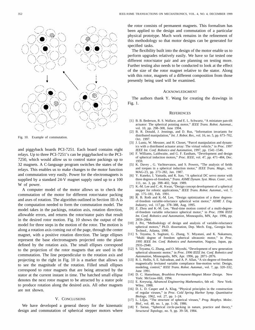
A computer model of the motor allows us to check thecommutation of the motor for different rotor/stator packingand axes of rotation. The algorithm outlined in Section III-A isthe computation needed to form the commutation model. Themodel takes in the packings, rotation axis, rotation direction,allowable errors, and returns the rotor/stator pairs that resultin the desired rotor motion. Fig. 10 shows the output of themodel for three steps in the motion of the rotor. The motion isalong a rotation axis coming out of the page, through the centermagnet, with a positive rotation direction. The large ellipsesrepresent the base electromagnets projected onto the planedefined by the rotation axis. The small ellipses correspondto the projection of the rotor magnets that are used in thecommutation. The line perpendicular to the rotation axis andprojecting to the right in Fig. 10 is a marker that allows usto see the magnitude of the rotation. Filled small ellipsescorrespond to rotor magnets that are being attracted by thestator at the current instant in time. The hatched small ellipsedenotes the next rotor magnet to be attracted by a stator poleto produce rotation along the desired axis. All other magnetsare not shown.
V. CONCLUSIONS
We have developed a general theory for the kinematicdesign and commutation of spherical stepper motors where
the rotor consists of permanent magnets. This formalism hasbeen applied to the design and commutation of a particularphysical prototype. Much work remains in the refinement ofthis methodology so that motor designs can be generated forspecified tasks.
The flexibility built into the design of the motor enable us toperform upgrades relatively easily. We have so far tested onedifferent rotor/stator pair and are planning on testing more.Further testing also needs to be conducted to look at the effectof the size of the rotor magnet relative to the stator. Alongwith this rotor, magnets of a different composition from thosepresently being used will be examined.
ACKNOWLEDGMENT
The authors thank Y. Wang for creating the drawings inFig. 1.
REFERENCES
[1] B. B. Bederson, R. S. Wallace, and E. L. Schwartz, “A miniature pan-tiltactuator: The spherical pointing motor,”IEEE Trans. Robot. Automat.,vol. 10, pp. 298–308, June 1994.
[2] B. R. Donald, J. Jennings, and D. Rus, “Information invariants fordistributed manipulation,”Int. J. Robot. Res., vol. 16, no. 5, pp. 673–702,Oct. 1997.
[3] J. Luntz, W. Messner, and H. Choset, “Parcel manipulation and dynam-ics with a distributed actuator array: The virtual vehicle,” inProc. 1997IEEE Int. Conf. Robotics and Automation, 1997, pp. 1541–1546.
[4] F. Williams, Laithwaite, and G. F. Eastham, “Development and designof spherical induction motors,”Proc. IEEE, vol. 47, pp. 471–484, Dec.1959.
[5] K. Davey , G. Vachtsevanos, and S. Powers, “The analysis of fieldsand torques in a spherical induction motor,”IEEE Trans. Magn., vol.MAG-23, pp. 273–282, Jan. 1987.
[6] Y. Kaneko, I. Yamada, and K. Itao, “A spherical DC servo motor withthree degrees-of-freedom,”Trans. ASME Dynam. Syst. Meas. Contr., vol.111, no. 3, pp. 398–402, Sept. 1989.
[7] K.-M. Lee and C.-K. Kwan, “Design concept development of a sphericalstepper for robotic applications,”IEEE Trans. Robot. Automat., vol. 7,pp. 175–181, Feb. 1991.
[8] R. B. Roth and K.-M. Lee, “Design optimization of a three degrees-of-freedom variable-reluctance spherical wrist motor,”ASME J. Eng.Industry, vol. 117,pp. 378–388, Aug. 1995.
[9] Z. Zhou and K.-M. Lee, “Real-time motion control of a multi-degree-of-freedom variable reluctance spherical motor,” inProc. 1996 IEEEInt. Conf. Robotics and Automation, Minneapolis, MN, Apr. 1996, pp.2859–2864.
[10] J. Pei, “Methodology of design and analysis of variable-reluctancespherical motors,” Ph.D. dissertation, Dep. Mech. Eng., Georgia Inst.Technol., Atlanta, 1990.
[11] S. Toyama, S. Sugitani, G. Zhang, Y. Miyatani, and K. Nakamura,“Multi degree of freedom spherical ultrasonic motor,” inProc.1995 IEEE Int. Conf. Robotics and Automation, Nagoya, Japan, pp.2935–2940.
[12] S. Toyama, G. Zhang, and O. Miyoshi, “Development of new generationspherical ultrasonic motor,” inProc. 1996 IEEE Int. Conf. Robotics andAutomation, Minneapolis, MN, Apr. 1996, pp. 2871–2876.
[13] R. L. Hollis, S. E. Salcudean, and A. P. Allan, “A six-degree-of-freedommagnetically levitated variable compliance fine-motion wrist: Design,modeling, control,”IEEE Trans. Robot. Automat., vol. 7, pp. 320–332,June 1991.
[14] D. C. Hanselman,Brushless Permanent-Magnet Motor Design. NewYork: McGraw-Hill, 1994.
[15] E. Kreyszig,Advanced Engineering Mathematics, 6th ed. New York:Wiley, 1988.
[16] D. L. D. Casper and A. Klug, “Physical principles in the constructionof regular viruses,” inProc. Cold Spring Harbor Symp. QuantitativeBiology, 1962, vol. 27, pp. 1–24.
[17] L. Liljas, “The structure of spherical viruses,”Prog. Biophys. Molec.Biol., vol. 48, no. 1, pp. 1–36, 1986.
[18] T. Tarnai, “Spherical circle-packing in nature, practice and theory,”Structural Topology, no. 9, pp. 39–58, 1984.

CHIRIKJIAN AND STEIN: SPHERICAL STEPPER MOTOR 353
[19] B. W. Clare and D. L. Kepert, “The optimal packing of circles on asphere,”J. Math. Chem., vol. 6, no. 4, pp. 325–349, May 1991.
[20] D. A. Kottwitz, “The densest packing of equal circles on a sphere,”ActaCrystallogr. A, vol. 47, pt. 3, pp. 158–165, May 1991.
[21] L. Fejes-Toth, “Stable packing of circles on the sphere,”StructuralTopology, no. 11, pp. 9–14, 1985.
[22] J. R. Baumgardner and P. O. Frederickson, “Icosahedral discretization ofthe two-sphere,”SIAM J. Numer. Anal., vol. 22, no. 6, pp. 1107–1115,Dec. 1985.
[23] G. S. Chirikjian and S. Zhou, “Metrics on motion and deformation ofsolid models,”ASME J. Mech. Des., vol. 120, no. 2, pp. 252–261, June1998.
[24] F. C. Park, “Distance metrics on the rigid-body motions with applica-tions to mechanism design,”Trans. ASME, J. Mech. Des., vol. 117, pp.48–54, Mar. 1995.
[25] F. C. Park and B. Ravani, “B́ezier curves on Riemannian manifolds andLie groups with kinematics applications,”Trans. ASME, J. Mech. Des.,vol. 117, pp. 36–40, Mar. 1995.
[26] J. M. McCarthy,Introduction to Theoretical Kinematics. Cambridge,MA: MIT Press, 1990.
[27] K. R. Etzel and J. M. McCarthy, “Spatial motion interpolation inan image space of SO(4),” inProc. 1996 ASME Design EngineeringTechnical Conf. and Computers in Engineering Conf., Irvine, CA, Aug.18–22, 1996.
[28] J. W. Cooley and J. Tukey, “An algorithm for the machine calculationof complex Fourier series,”Math. Comput., vol. 19, pp. 297–301, Apr.1965.
[29] J. R. Driscoll and D. Healy, “Computing Fourier transforms andconvolutions on the 2-sphere,”Adv. Appl. Math., vol. 15, no. 2, pp.202–250, June 1994.
[30] D. K. Maslen and D. N. Rockmore, “Generalized FFTs—A survey ofsome recent results,” inDIMACS Series in Discrete Mathematics andTheoretical Computer Science, vol. 28. Providence, RI: AMS, 1997,pp. 183–237.
[31] I. M. Gel’fand, R. A. Minlos, and Z. Ya. Shapiro,Representations ofthe Rotation and Lorentz Groups and Their Applications. New York:Macmillan, 1963.
[32] D. A. Varshalovich, A. N. Moskalev, and V. K. Khersonskii,QuantumTheory of Angular Momentum. Singapore: World Scientific, 1988.
[33] N. J. Vilenkin and A. U. Klimyk, Representation of Lie Groups andSpecial Functions, vols. 1–3. Dordrecht, The Netherlands, Kluwer,1991.
[34] G. S. Chirikjian and A. B. Kyatkin,Engineering Applications of Non-commutative Harmonic Analysis. Boca Raton, FL: CRC Press, to bepublished.
Gregory S. Chirikjian (M’93) was born in NewBrunswick, NJ, in 1966. He received the B.S.E.degree in engineering mechanics, the M.S.E. degreein mechanical engineering, and the B.A. degree inmathematics from The Johns Hopkins University,Baltimore, MD, in 1988 and the Ph.D. degree fromCalifornia Institute of Technology, Pasadena, in1992.
Since the summer of 1992, he has been with theDepartment of Mechanical Engineering, The JohnsHopkins University, where he is currently an Asso-
ciate Professor. His research interests include the kinematic analysis, motionplanning, design, and implementation of “hyper-redundant,” “metamorphic,”and “binary” manipulators. In recent years, he has expanded the scope of hisresearch to include applications of group theory in a variety of engineeringdisciplines.
Dr. Chirikjian was a 1993 National Science Foundation Young Investigator,a 1994 Presidential Faculty Fellow, and a 1996 recipient of the AmericanSociety of Mechanical Engineers Pi Tau Sigma Gold Medal.
David Stein (S’99) was born in Brooklyn, NY,in 1974. He received B.S.E. degrees in biomedicalengineering and in engineering mechanics in 1997and the M.S.E degree in mechanical engineering in1999 from The Johns Hopkins University, Balti-more, MD, where he is currently working towardthe Ph.D. degree in mechanical engineering.
His research interests are in discrete-state me-chanical systems.