kinematic constraints and offline programming in …
TRANSCRIPT
P. Kržič et al. Kinematička ograničenja i izvanmrežno programiranje kod robotskih obradnih programa
Tehnički vjesnik 20, 1(2013), 117-124 117
ISSN 1330-3651 (Print), ISSN 1848-6339 (Online) UDC/UDK 621.865.8:004.896
KINEMATIC CONSTRAINTS AND OFFLINE PROGRAMMING IN ROBOTIC MACHINING APPLICATIONS Primož Kržič, Franci Pušavec, Janez Kopač
Original scientific paper Robotic machining applications are becoming more and more frequent in the world of industrial robots. However, their kinematic complexity still offers many challenges. This work presents an overview of kinematic constraints, which are important for the offline programming of industrial robots for the use in machining applications. The three possible solutions for overcoming kinematic constraints (end-effector rotation, part translation, and part rotation) are presented. The computer algorithm for avoiding such constraints was developed, programmed and tested with a case study. Results show that kinematic constraints can be automatically avoided by implementation of developed avoidance algorithm into the offline programming software for robotic machining. Keywords: constraint, industrial robot, kinematic, machining, offline programming
Kinematička ograničenja i izvanmrežno programiranje kod robotskih obradnih programa
Izvorni znanstveni članak Robotski obradni programi postaju sve učestaliji u svijetu industrijskih robota. Međutim, njihova kinematička složenost još uvijek nudi mnogo izazova. Ovaj rad daje pregled kinematičkih ograničenja, koja su važna za izvanmrežno programiranje industrijskih robota za uporabu kod obradnih programa. Prikazana su tri moguća rješenja za prevladavanje kinematičkih ograničenja (end-effector rotacija, djelomična translacija i djelomična rotacija). Razvijen je računalni algoritam za izbjegavanje takvih ograničenja, programiran i testirani analizom slučaja. Rezultati pokazuju da kinematička ograničenja mogu biti automatski izbjegnuta primjenom razvijenog algoritma izbjegavanja kod izvanmrežnog programiranja softvera za robotsku obradu odvajanjem čestica. Ključne riječi: industrijski robot, izvanmrežno programiranje, kinematički, ograničenje, strojna obrada
1 Introduction
IFR Statistical Department [1] reports that there are
more than 1 million industrial 6-Degree-Of-Freedom (6-DOF) robot manipulators used worldwide. By rapid expansion of industrial 6-DOF robots they are not used exclusively for pick-and-place operations any more. Robotic machining is one field where they are becoming more and more present. Even robot manufacturers have noticed the change in perception of industrial robots and they have already started to offer models intended for specific usage in machining applications. There are many reasons for the expansion of industrial robots into the CNC world [2]. Two main reasons that should be exposed
are the greater flexibility of industrial robots compared to conventional CNC machines and the lower price of robotic machining cells compared to conventional CNC machines with similar work envelope. When comparing the programming solutions between pick-and-place operations and robotic machining, one difference becomes evident among others: complexity of tool trajectories. Trajectories for robotic machining can be much more complex and many times contain thousands of toolpath points. In [3] Pan and Zhang and in [4] authors have already recognized that this complexity means that the only practical way to generate such programs would be offline programming using CAD/CAM software modules. Kinematic constraints of the 6-DOF robot manipulator are one of the main drawbacks for the further expansion of robot machining. As previously published by Pan [5] Computer Aided Manufacturing (CAM) systems, currently used for programming CNC machines, do not yet include algorithms that would enable the automatic avoidance of these constraints. The lack of adequate tools to automatically avoid kinematic
constraints, when preparing a program for the robotic machining means that the programmer has to solve them mainly by trial-and-error method. This method is time-demanding and sometimes does not allow finding optimal solution in a given timeframe. The work is organized as follows. An overview of kinematic constraints and related work is shown in Section 2. Section 3 addresses different methods to avoid kinematic constraints. The algorithm for finding, visualizing and avoiding kinematic constraints is covered in Section 4. Application and experimental results are presented in Section 5 and finally, the conclusion follows in Section 6. 2 Robotic machining via offline programming and
kinematic constraints Offline programming is the technique of generating a
robot program without using a real machine. As reported by Carvalho in [6] it presents several advantages over the online method, some of which are described below: - NC programs are prepared without interruptions of
robot operation, resulting in reduction of robot down time.
- Programmer is removed from potentially dangerous environment, as most of the program development is executed away from the robot.
- Because offline methods include a simulation of the process there is a greater possibility for optimization of the workspace layout and the planning of robot tasks.
- New programs can include previously developed routines.
- Program changes can be done quickly by substituting only the necessary part of the program.
Kinematic constraints and offline programming in robotic machining applications P. Kržič et al.
118 Technical Gazette 20, 1(2013), 117-124
- Information from the environment (i.e. computer integrated manufacturing system; CAD/CAM systems) can be incorporated into programs which can increase the accuracy of the process. When using offline programming to create complex
trajectories that are intended for machining with industrial robots we come across constraints that are much more evident with 6-DOF industrial robots than with conventional CNC machine tools. As stated by [7] these constraints are a direct result of industrial robots kinematic structure with 6 rotational joints. The main issue with such kinematic structure from the CNC programming standpoint is that moving of these joints during movement along toolpath cannot be easily predicted without using precise simulation of robot movements. There are three main kinematic constraints of industrial robots that can greatly complicate the programming of toolpath trajectories: joint limits, singularities and workspace limits.
Joint limits induced kinematical constraints are the consequence of mechanical construction of robot joints, where the working limit for each of these joints rarely exceeds -/+ 360 degrees. Chen and Sheng [8] have recognized that the main reason for this limitation is the construction of the end-effector and its electrical power and/or compressed air supply rather than the mechanical construction of the joint. Electrical cables for end-effectors power supply and pipes for compressed air or coolant supply are most often mounted on the outside of the manipulator arm and they do not allow joint rotations that are larger than -/+ 360 degrees.
Singularity position is a position of the robot end-effector in the robot workspace, where the mobility of the robot is reduced and the inverse kinematics may show infinite solutions. Small end-effectors velocities may cause very large joint velocities [9]. As shown by Hayes and Husty [10], there are generally 3 types of singularity positions: elbow, shoulder and wrist singularity.
Working space limitation is another important factor in offline programming for robotic machining. The main issue regarding the workspace is the fact that the shape of working space for the 6-DOF industrial robot is not in the shape of a block compared to conventional CNC machines. Reachability constraint becomes important when a robot arm cannot reach the point that is out of the working envelope of the robot.
In order to successfully finish the robotic machining the trajectory must be free of all three previously described kinematic constraints.
3 Overview of methods to avoid kinematic constraints in
robotic machining When dealing with kinematic constraints of industrial
robots used in machining operations, we limited possible solutions to only those that did not require changing position or orientation of a tool in a part coordinate system for any toolpath points that were previously calculated by the CAM software. This means that the toolpath trajectory cannot be changed in order to overcome kinematic constraints. The proposed solutions have also been used by several authors [11, 12, 13].
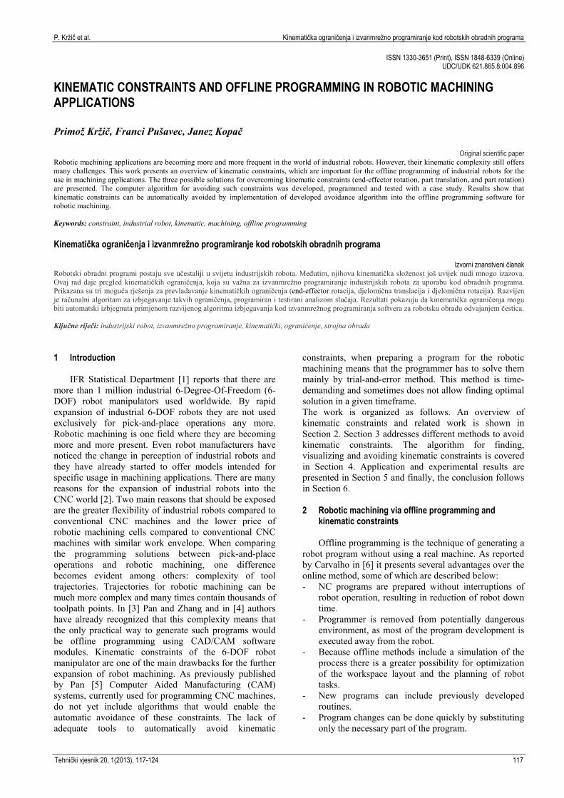
3.1 End-effector rotation The first method is the rotation of the end-effector
around the tool symmetry axis. The motion of the end-effector usually required by a task is the full 6-DOF. However, many robotic industrial tasks, including robotic machining, require less than 6-DOF, because of the presence of a tool symmetry axis. Huo and Baron [12] proved that the general task of machining requires 3-DOF for the displacement of the end-point of the tool, but only 2 additional DOF for its orientation. The rotation of the end-effector around the tool axis is clearly irrelevant to the view of the task to be accomplished. By rotating the end-effector around the tool symmetry axis we can change the position of all six joints of the robot arm and at the same time do not change the position and orientation of the tool according to the part. This solution can greatly improve the possibility to successfully finish the toolpath that was previously unachievable due to kinematic constraints.
Figure 1 Method for solving kinematic constraints by rotating end-
effector around tools symmetry axis
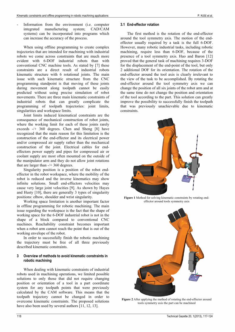
Figure 2 After applying the method of rotating the end-effector around
tools symmetry axis the part can be machined

P. Kržič et al. Kinematička ograničenja i izvanmrežno programiranje kod robotskih obradnih programa
Tehnički vjesnik 20, 1(2013), 117-124 119
Fig. 1 shows a part which is placed at such a position in a robot workspace that machining is not possible due to the robots joint limits. By rotating the end-effector around the tool symmetry axis (Fig. 2) the same part at the same position becomes reachable and can now be machined. 3.2 Part translation
The second method for resolving kinematic
constraints is the change of the part position in the robot workspace. Fig. 3 shows that at the beginning the part is being positioned too close to the robot base and is therefore unreachable to its end-effector. By repositioning of the part away from the robot base it becomes reachable to the end-effector and can be machined (Fig. 4).
Figure 3 Method for solving kinematic constraints by repositioning the
part
Figure 4 After applying the method of repositioning the part can be
machined
3.3 Part rotation The third valid method to solve kinematic constraints
is the part rotation. This solution is presented in Fig. 5, where a part is positioned too close to a robot base in
order to be successfully reached and machined. By changing its orientation the robot can successfully finish the toolpath (Fig. 6).
Figure 5 Method for solving kinematic constraints by reorienting the
part
Figure 6 After applying the method of reorienting the part can be
machined
4 Algorithm for avoiding kinematic constraints The intention of this algorithm is to implement
previously described methods for avoiding kinematic constraints in order to successfully complete the programmed trajectory for machining a part. Kamrani [13] has stated that the toolpath is admissible if the end-effector of the robot can reach all the points on the toolpath in the predefined configuration. The main methods we used in the developed algorithm were discretization and solution method ordering. 4.1 Discretization
As previously described by Zacharias [14] the
theoretically possible workspace of the robot arm can be

Kinematic constraints and offline programming in robotic machining applications P. Kržič et al.
120 Technical Gazette 20, 1(2013), 117-124
encapsulated by a cube with a side length of two arm lengths centered at the robot arm base (Fig. 7). The work of Kamrani [13] and Zacharias [14] has shown that the best practice to calculate the admissibility of the toolpath when it is placed at different positions in the robot workspace is to discretize the encapsulated cube into smaller blocks. The calculation then checks the admissibility of the given toolpath placed at each corner of the sub block. Similarly, we also use discretization of the robot end-effectors rotation around tool axis and part rotation around global X-, Y- and Z-axis.
Figure 7 Robot workspace is overestimated and subdivided
4.2 Ordering of the solution methods
Our work aims to address the issue of finding the
machining configurations (orientation of the end-effector, part location, part orientation) where the machining is possible. We propose to use the specially ordered combination of all previously mentioned solutions which will be further explained in the following paragraph.
The main reason for this approach is the need to minimize the calculation time and to maximize the number of possible configurations which are checked for admissibility. To minimize the calculation time we decided to order possible combinations by the number of DOF that each solution takes. In robotic machining applications it is preferred that the part predefined position and orientation changes as little as possible from the predefined position. Every additional DOF the proposed solution uses means that the change in position and/or orientation complicates the clamping of the part. For instance, the solution with the end-effector rotation does not necessarily require movement of the clamped part. It therefore requires 0 DOF. Part reposition can require one, two or three DOF which in real world requires re-clamping of the part. If the part must be reoriented this solution can take up to 6 DOF what in reality often means that a new clamping device must be constructed. The first solution method with rotation of the end-effector around its axis is therefore more preferred than the repositioning or reorienting the part. After taking these characteristics of the possible solutions into consideration we have prepared Tab. 1 that recognizes the most important types of kinematic constraints and the
order of each solution taken into consideration for solving these constraints.
Table 1 Proposed methods to avoid kinematic constraints and their
proposed order
Method Method description 1 Rotate end-effector around tool axis 2 Reposition the part 3 Rotate the part
By using this matrix in a developed algorithm we
predicted that each level of solution methods would be used after a previous level method was found to be unsuccessful. If the previous level solution returned an admissible configuration all higher level solutions would be discarded from the calculation process. 4.3 Description of the developed algorithm
The flow of the developed algorithm is depicted in
Fig. 8. The algorithm first imports the CL (Cutter Location) data which have been previously calculated by a CAM (Computer Aided Manufacturing) program. At the same time the Machining Configurations Settings window (Fig. 9) is shown. In this window user can set additional limitation parameters. Tab. 2 shows all the additional parameters that can be specified in order to set the discretization parameters of algorithm. We also have an option to minimize the calculation time by omitting the inverse kinematics calculation at some of the configurations. For instance if it is predicted that the part will be clamped on the working table we can input the parameters in such a way that only configurations with parts Z-coordinate at the top of the clamping table are used and calculated.
After the parameters are input and confirmed the algorithm calculates the reverse kinematics for the toolpath at the initial part position (Fig. 8). The role of the inverse kinematic calculation is to check each point in the toolpath for possible kinematic constraints [15]. If all the points in the toolpath can be reached without any reported kinematic constraints the toolpath at the current configuration is marked as admissible (valid).
Figure 8 User interface window for entering additional parameters

P. Kržič et al. Kinematička ograničenja i izvanmrežno programiranje kod robotskih obradnih programa
Tehnički vjesnik 20, 1(2013), 117-124 121
Figure 9 Flowchart diagram of the algorithm
Table 2 The user interface input parameters overview
Part repositioning discretization parameters Minimum part position values Min X / mm Min Y / mm Min Z / mm Maximum part position values Max X / mm Max Y / mm Max Z / mm Subdivision block size Delta X / mm Delta Y / mm Delta Z / mm End-effector rotation discretization parameters Minimum end-effector rotation value T Min RZ / mm Maximum end-effector rotation value T Max RZ / mm End-effector rotation step T Delta RZ / mm Part rotation discretization parameters Minimum part rotation values P Min RX / mm P Min RY / mm P Min RZ / mm Maximum part rotation values P Max RX / mm P Max RY / mm P Max RZ / mm Part rotation step P Delta RX / mm P Delta RY / mm P Delta RZ / mm
Kinematic constraints and offline programming in robotic machining applications P. Kržič et al.
122 Technical Gazette 20, 1(2013), 117-124
If this calculation returns an invalid solution the algorithm continues the iteration process and checks all the configurations with rotated end-effector. If this additional iteration through all the preset end-effector rotation configurations still returns no admissible solution the algorithm continues with iterating through all the preset part orientation configurations. After the completion of the iteration the inverse kinematics solution is recorded into the database for later use. If the valid solution is found at any of the previously described steps the algorithm increments the parts position and starts iteration process for all the predefined configurations at the new part position.
When all the configurations at each of the predefined part positions have been checked the process is stopped and the visualization module is run. This module reads the data from previously saved database and presents the results on the screen. 4.4 Results visualization
Visualization was used to clearly represent the
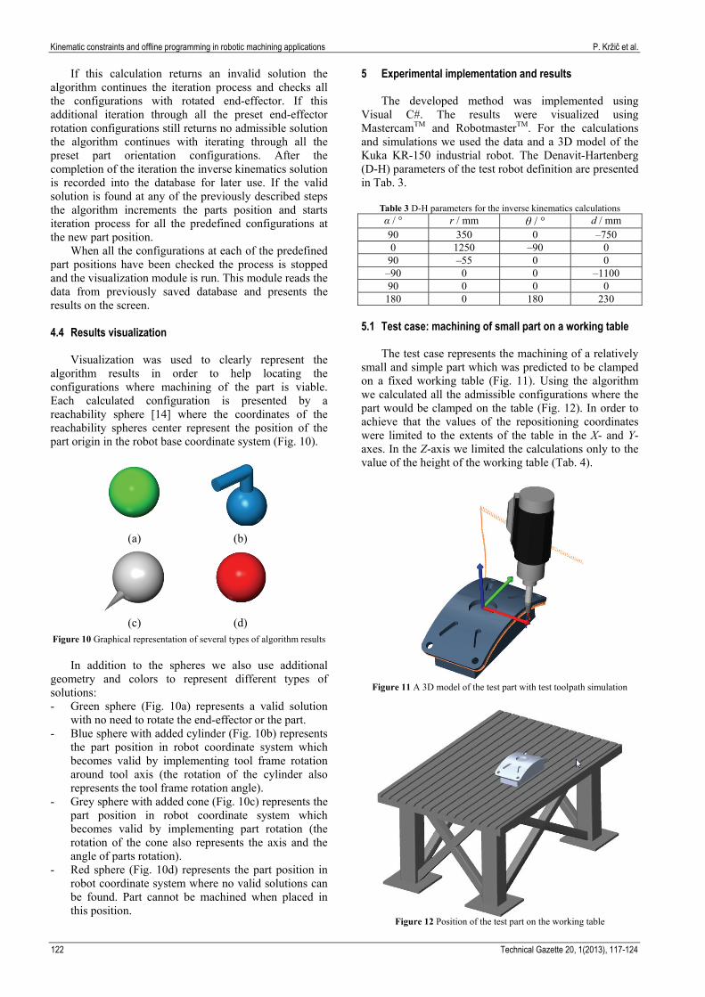
algorithm results in order to help locating the configurations where machining of the part is viable. Each calculated configuration is presented by a reachability sphere [14] where the coordinates of the reachability spheres center represent the position of the part origin in the robot base coordinate system (Fig. 10).
(a) (b)
(c) (d) Figure 10 Graphical representation of several types of algorithm results
In addition to the spheres we also use additional
geometry and colors to represent different types of solutions: - Green sphere (Fig. 10a) represents a valid solution
with no need to rotate the end-effector or the part. - Blue sphere with added cylinder (Fig. 10b) represents
the part position in robot coordinate system which becomes valid by implementing tool frame rotation around tool axis (the rotation of the cylinder also represents the tool frame rotation angle).
- Grey sphere with added cone (Fig. 10c) represents the part position in robot coordinate system which becomes valid by implementing part rotation (the rotation of the cone also represents the axis and the angle of parts rotation).
- Red sphere (Fig. 10d) represents the part position in robot coordinate system where no valid solutions can be found. Part cannot be machined when placed in this position.
5 Experimental implementation and results The developed method was implemented using
Visual C#. The results were visualized using MastercamTM and RobotmasterTM. For the calculations and simulations we used the data and a 3D model of the Kuka KR-150 industrial robot. The Denavit-Hartenberg (D-H) parameters of the test robot definition are presented in Tab. 3.
Table 3 D-H parameters for the inverse kinematics calculations α / ° r / mm θ / ° d / mm 90 350 0 –750 0 1250 –90 0
90 –55 0 0 –90 0 0 –1100 90 0 0 0 180 0 180 230
5.1 Test case: machining of small part on a working table
The test case represents the machining of a relatively
small and simple part which was predicted to be clamped on a fixed working table (Fig. 11). Using the algorithm we calculated all the admissible configurations where the part would be clamped on the table (Fig. 12). In order to achieve that the values of the repositioning coordinates were limited to the extents of the table in the X- and Y-axes. In the Z-axis we limited the calculations only to the value of the height of the working table (Tab. 4).
Figure 11 A 3D model of the test part with test toolpath simulation
Figure 12 Position of the test part on the working table
P. Kržič et al. Kinematička ograničenja i izvanmrežno programiranje kod robotskih obradnih programa
Tehnički vjesnik 20, 1(2013), 117-124 123
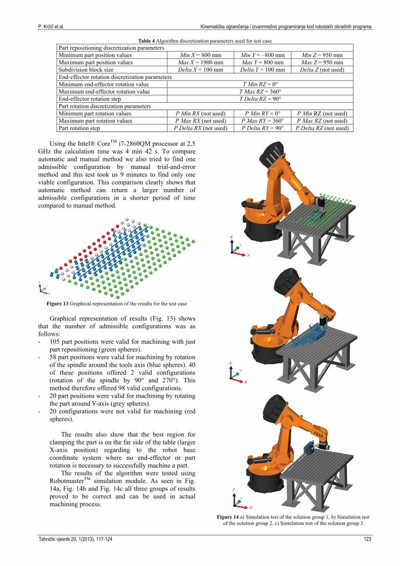
Table 4 Algorithm discretization parameters used for test case Part repositioning discretization parameters Minimum part position values Min X = 800 mm Min Y = –800 mm Min Z = 950 mm Maximum part position values Max X = 1900 mm Max Y = 800 mm Max Z = 950 mm Subdivision block size Delta X = 100 mm Delta Y = 100 mm Delta Z (not used) End-effector rotation discretization parameters Minimum end-effector rotation value T Min RZ = 0° Maximum end-effector rotation value T Max RZ = 360° End-effector rotation step T Delta RZ = 90° Part rotation discretization parameters Minimum part rotation values P Min RX (not used) P Min RY = 0° P Min RZ (not used) Maximum part rotation values P Max RX (not used) P Max RY = 360° P Max RZ (not used) Part rotation step P Delta RX (not used) P Delta RY = 90° P Delta RZ (not used)
Using the Intel® CoreTM i7-2860QM processor at 2,5
GHz the calculation time was 4 min 42 s. To compare automatic and manual method we also tried to find one admissible configuration by manual trial-and-error method and this test took us 9 minutes to find only one viable configuration. This comparison clearly shows that automatic method can return a larger number of admissible configurations in a shorter period of time compared to manual method.
Figure 13 Graphical representation of the results for the test case
Graphical representation of results (Fig. 13) shows
that the number of admissible configurations was as follows: - 105 part positions were valid for machining with just
part repositioning (green spheres). - 58 part positions were valid for machining by rotation
of the spindle around the tools axis (blue spheres). 40 of these positions offered 2 valid configurations (rotation of the spindle by 90° and 270°). This method therefore offered 98 valid configurations.
- 20 part positions were valid for machining by rotating the part around Y-axis (grey spheres).
- 20 configurations were not valid for machining (red spheres).
The results also show that the best region for clamping the part is on the far side of the table (larger X-axis position) regarding to the robot base coordinate system where no end-effector or part rotation is necessary to successfully machine a part.
The results of the algorithm were tested using RobotmasterTM simulation module. As seen in Fig. 14a, Fig. 14b and Fig. 14c all three groups of results proved to be correct and can be used in actual machining process.
Figure 14 a) Simulation test of the solution group 1, b) Simulation test
of the solution group 2, c) Simulation test of the solution group 3

Kinematic constraints and offline programming in robotic machining applications P. Kržič et al.
124 Technical Gazette 20, 1(2013), 117-124
6 Conclusions The presented research shows that kinematic
constraints of industrial robot for machining applications can be avoided by implementing end-effector rotation around tool axis, part repositioning and/or part reorientation. The algorithm for calculating valid configurations using these solutions was developed and programmed using Visual C++. It was successfully tested on an industrial case and the results were confirmed by the RobotmasterTM robot simulation software. The main advantage of the proposed method compared to the state-of-the art in the offline programming, is synergetic implementation of three separate methods into one algorithm. By combining all three methods kinematic constraints can be resolved reliably and much faster. The main advantage lies in the fact that all three methods are considered synchronal. Additionally, the developed visualization helps the user to better recognize positions of critical zones and by this the final solution can be significantly closer to the optimal part position. Implemented algorithm (Fig. 9) also allows the user to set the input parameters in such a way that only a part of the robot workspace is being checked. This enables further shortening of the calculation times, while the inverse kinematics does not have to be calculated over the whole robot workspace.
The proposed method has been tested on the case study. Results of the test show that the algorithm can significantly improve the speed and quality of calculating the valid configurations/tool path for robotic machining compared to manual trial-and-error method.
7 References [1] Sakakibara, S. The continuing success story of industrial
robots. International Federation of Robotics IFR. 2011. URL: http://www.worldrobotics.org/index.php?id=home &news_id=264. (20-1-2013).
[2] Milutinovic, D.; Glavonjic, M.; Slavkovic, N.; Dimic, Z.; Zivanovic, S.; Kokotovic, B.; Tanovic, L. Reconfigurable robotic machining system controlled and programmed in a machine tool manner // The International Journal of Advanced Manufacturing Technology. 53, 9-12 (2010), pp. 1217-1229.
[3] Pan, Z.; Zhang, H. Robotic machining from programming to process control: a complete solution by force control // Industrial Robot: An International Journal. 35, 5 (2008), pp. 400-409.
[4] Ficko, M.; Balic, J.; Pahole, I.; Senveter, J.; Brezovnik, S.; Klancnik, S. Expectations of automatic programming of CNC machine tools // Advances in Production Engineering and Management. 5, 3 (2010), pp. 193-199.
[5] Pan, Z.; Polden, J.; Larkin, N.; Van Duin, S.; Norrish, J. Recent progress on programming methods for industrial robots // Robotics and Computer-Integrated Manufacturing. 28, 2 (2012), pp. 87-94.
[6] Carvalho, G. C.; Siqueira, M. L.; Absi-Alfaro, S. C. Off-line programming of flexible welding manufacturing cells // Journal of Materials Processing Technology. 78, 1-3 (1998), pp. 24-28.
[7] Gotlih, K.; Kovac, D.; Vuherer, T.; Brezovnik, S.; Brezocnik, M.; Zver, A. Velocity anisotropy of an industrial robot // Robotics and Computer-Integrated Manufacturing. 27, 1 (2011), pp. 205-211.
[8] Chen, H.; Sheng, W. Transformative CAD based industrial robot program generation // Robotics and Computer-Integrated Manufacturing. 27, 5 (2011), pp. 942-948.
[9] Pires, J. N. Industrial Robots Programming: Building Applications for the Factories of the Future. Springer, 2006.
[10] Hayes, M. J. D.; Husty, M. L. Singular Configurations of Wrist-Partitioned 6R Serial Robots : a Geometric Perspective for Users // Transactions of the Canadian Society for Mechanical Engineering. 26, 1 (2002), pp. 41-55.
[11] Vosniakos, G.-C.; Matsas, E. Improving feasibility of robotic milling through robot placement optimisation // Robotics and Computer-Integrated Manufacturing. 26, 5 (2010), pp. 517-525.
[12] Huo, L.; Baron, L. Kinematic Inversion of Functionally-Redundant Serial Manipulators: Application to Arc-Welding // Transactions of the Canadian Society for Mechanical Engineering. 29, 4 (2005), pp. 679-690.
[13] Kamrani, B.; Berbyuk, V.; Wäppling, D.; Stickelmann, U.; Feng, X. Optimal robot placement using response surface method // The International Journal of Advanced Manufacturing Technology. 44, 1-2 (2008), pp. 201-210.
[14] Zacharias, F.; Borst, C.; Hirzinger, G. Capturing robot workspace structure: representing robot capabilities. // Proceedings of the IEEE/RSJ International Conference on Intelligent Robots and Systems / USA, CA, 2007, pp. 3229-3236.
[15] Craig, J. J. Introduction to Robotics: Mechanics and Control. Prentice Hall, New Jersey, USA, 2004.
Authors’ addresses: Primož Kržič, uni.dipl.ing. University of Ljubljana Faculty of Mechanical Engineering Aškerčeva 6, 1000 Ljubljana, Slovenia E-mail: [email protected] Franci Pušavec, assist.prof.dr. University of Ljubljana Faculty of Mechanical Engineering Aškerčeva 6, 1000 Ljubljana, Slovenia E-mail: [email protected] Janez Kopač, prof.dr. University of Ljubljana Faculty of Mechanical Engineering Aškerčeva 6, 1000 Ljubljana, Slovenia E-mail: [email protected]