kinematic analysis of robotic complex within the
TRANSCRIPT
Kinematic analysis of robotic complex within the SOLIDWORKS Motion system
Sergey Igorevich Anciferov Belgorod State Technological University named after
V.G. Shukhov Belgorod, Russia
308012, Kostukov St., 46 [email protected]
Elena Vladimirovna Gaponenko Belgorod State Technological University named after
V.G. Shukhov Belgorod, Russia
308012, Kostukov St., 46 [email protected]
Leonid Sergeevich Kulakov Belgorod State Technological University named after V.G. Shukhov
Belgorod, Russia 308012, Kostukov St., 46 [email protected]
Abstract—The paper presents the kinematic analysis regarding the motion of a robotic complex with relative handling modules via the SolidWorks Motion system based on the designed 3D model. The analysis considered such motion elements as motion restriction, material properties, weight, speeds and contacts of components. The results of motion modeling of the module for installation of the tool and the module for installation of the processed workpiece on the basis of tripods are given. In the course of modeling the real motion rods were replaced with interface units of the SolidWorks Motion application. The analysis resulted in the definition of the maximum movement of links. Besides, the adequacy of developed mobile parts and lack of conflicting links is defined. The motion trajectories of the output links of robotic complex are obtained. The analysis allows drawing conclusions on the motion trajectory fidelity of modules to perform processing of tools of various complexity. The obtained results may be used in the design of robotic complex with relative handling modules.
Keywords—robotic complex, relative handling mechanism, SolidWorks Motion, kinematic analysis, trajectory.
I. INTRODUCTION The creation of new types of high-performance
innovative equipment for various applications (machining, cutting, welding, assembling, painting) may cause problems related to the development of new design and technical solutions of their arrangement ensuring complex types of an output link motion in space and high positioning accuracy. One of the possible solutions to this problem is the use of parallel structure mechanisms for relative handling [1].
At present, the industry has achieved a considerable progress in the study of parallel mechanisms [2-8].
One of the key tasks in the design of parallel robots is the analysis of links motion and the definition of working
area of output links that ensure the required trajectory of the motion, which makes it possible to avoid inaccuracies and failures of production and assembly of a full-scale prototype. CAD systems are used for this purpose, which allow obtaining the exact electronic model of a product within a relatively short time and to prepare it for kinematic analysis or for further study in mathematical packages [9, 10].
II. K INEMATIC ANALYSIS OF A ROBOTIC COMPLEX
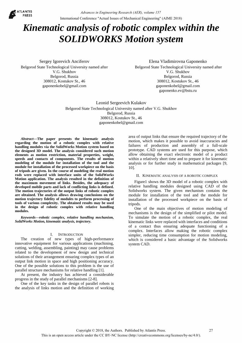
Figure1 shows the 3D model of a robotic complex with relative handling modules designed using CAD of the Solidworks system. The given mechanism contains the module for installation of the tool and the module for installation of the processed workpiece on the basis of tripods.
One of the main objectives of motion modeling of mechanisms is the design of the simplified or pilot model. To simulate the motion of a robotic complex, the real kinematic links were replaced with interfaces and conditions of a contact thus ensuring adequate functioning of a complex. Interfaces allow making the robotic complex simpler, reducing time consumption for motion modeling, which is considered a basic advantage of the Solidworks system CAD.
27Copyright © 2018, the Authors. Published by Atlantis Press. This is an open access article under the CC BY-NC license (http://creativecommons.org/licenses/by-nc/4.0/).
International Conference "Actual Issues of Mechanical Engineering" (AIME 2018)Advances in Engineering Research (AER), volume 157
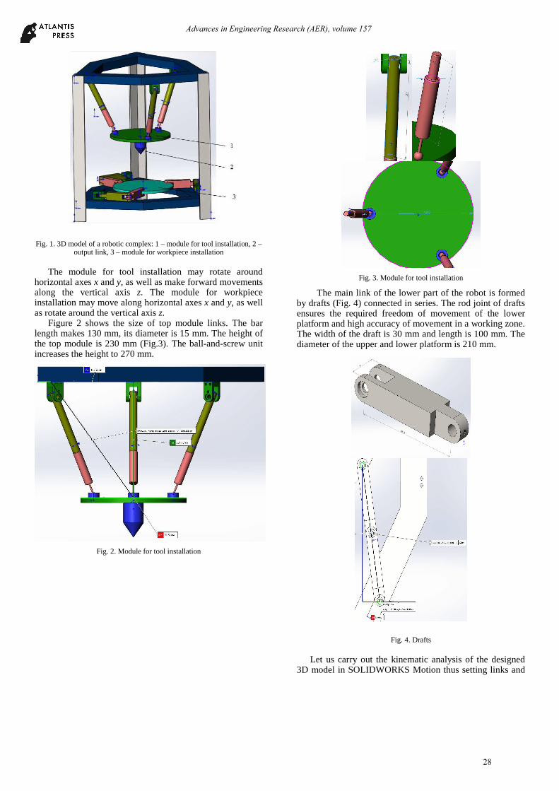
Fig. 1. 3D model of a robotic complex: 1 – module for tool installation, 2 –
output link, 3 – module for workpiece installation The module for tool installation may rotate around
horizontal axes x and y, as well as make forward movements along the vertical axis z. The module for workpiece installation may move along horizontal axes x and y, as well as rotate around the vertical axis z.
Figure 2 shows the size of top module links. The bar length makes 130 mm, its diameter is 15 mm. The height of the top module is 230 mm (Fig.3). The ball-and-screw unit increases the height to 270 mm.
Fig. 2. Module for tool installation
Fig. 3. Module for tool installation
The main link of the lower part of the robot is formed by drafts (Fig. 4) connected in series. The rod joint of drafts ensures the required freedom of movement of the lower platform and high accuracy of movement in a working zone. The width of the draft is 30 mm and length is 100 mm. The diameter of the upper and lower platform is 210 mm.
Fig. 4. Drafts Let us carry out the kinematic analysis of the designed
3D model in SOLIDWORKS Motion thus setting links and
28
Advances in Engineering Research (AER), volume 157
conditions for mobile elements that are close to real service conditions. The procedure of the motion analysis allows considering the physics of the assembly movement.
The motion study includes the analysis of such elements and parameters as motion restriction, material properties, weight, speeds and contacts of components.
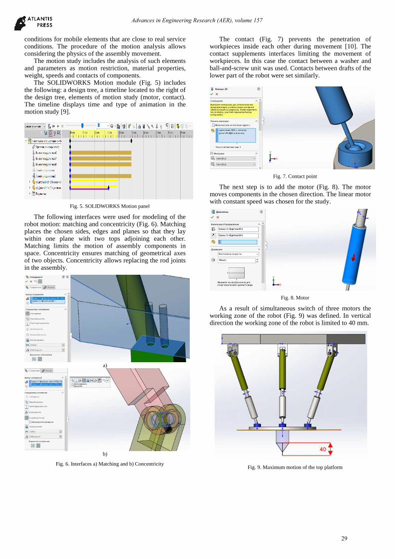
The SOLIDWORKS Motion module (Fig. 5) includes the following: a design tree, a timeline located to the right of the design tree, elements of motion study (motor, contact). The timeline displays time and type of animation in the motion study [9].
Fig. 5. SOLIDWORKS Motion panel
The following interfaces were used for modeling of the robot motion: matching and concentricity (Fig. 6). Matching places the chosen sides, edges and planes so that they lay within one plane with two tops adjoining each other. Matching limits the motion of assembly components in space. Concentricity ensures matching of geometrical axes of two objects. Concentricity allows replacing the rod joints in the assembly.
a)
b)
Fig. 6. Interfaces a) Matching and b) Concentricity
The contact (Fig. 7) prevents the penetration of workpieces inside each other during movement [10]. The contact supplements interfaces limiting the movement of workpieces. In this case the contact between a washer and ball-and-screw unit was used. Contacts between drafts of the lower part of the robot were set similarly.
Fig. 7. Contact point
The next step is to add the motor (Fig. 8). The motor moves components in the chosen direction. The linear motor with constant speed was chosen for the study.
Fig. 8. Motor
As a result of simultaneous switch of three motors the working zone of the robot (Fig. 9) was defined. In vertical direction the working zone of the robot is limited to 40 mm.
Fig. 9. Maximum motion of the top platform
29
Advances in Engineering Research (AER), volume 157
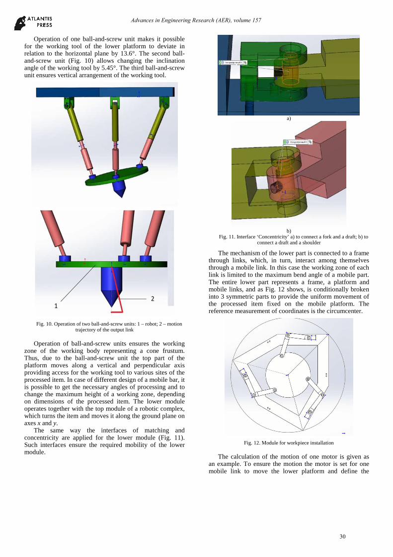
Operation of one ball-and-screw unit makes it possible for the working tool of the lower platform to deviate in relation to the horizontal plane by 13.6°. The second ball-and-screw unit (Fig. 10) allows changing the inclination angle of the working tool by 5.45°. The third ball-and-screw unit ensures vertical arrangement of the working tool.
Fig. 10. Operation of two ball-and-screw units: 1 – robot; 2 – motion
trajectory of the output link Operation of ball-and-screw units ensures the working
zone of the working body representing a cone frustum. Thus, due to the ball-and-screw unit the top part of the platform moves along a vertical and perpendicular axis providing access for the working tool to various sites of the processed item. In case of different design of a mobile bar, it is possible to get the necessary angles of processing and to change the maximum height of a working zone, depending on dimensions of the processed item. The lower module operates together with the top module of a robotic complex, which turns the item and moves it along the ground plane on axes x and y.
The same way the interfaces of matching and concentricity are applied for the lower module (Fig. 11). Such interfaces ensure the required mobility of the lower module.
a)
b)
Fig. 11. Interface ‘Concentricity’ a) to connect a fork and a draft; b) to connect a draft and a shoulder
The mechanism of the lower part is connected to a frame through links, which, in turn, interact among themselves through a mobile link. In this case the working zone of each link is limited to the maximum bend angle of a mobile part. The entire lower part represents a frame, a platform and mobile links, and as Fig. 12 shows, is conditionally broken into 3 symmetric parts to provide the uniform movement of the processed item fixed on the mobile platform. The reference measurement of coordinates is the circumcenter.
Fig. 12. Module for workpiece installation
The calculation of the motion of one motor is given as
an example. To ensure the motion the motor is set for one mobile link to move the lower platform and define the
30
Advances in Engineering Research (AER), volume 157
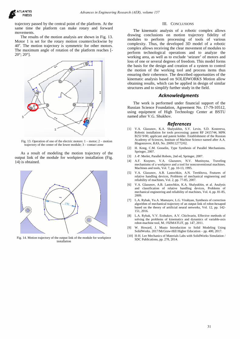
trajectory passed by the central point of the platform. At the same time the platform can make rotary and forward movements.
The results of the motion analysis are shown in Fig. 13. Motor 1 is set for the rotary motion counterclockwise by 40о. The motion trajectory is symmetric for other motors. The maximum angle of rotation of the platform reaches [-20°; 20°].
Fig. 13. Operation of one of the electric motors: 1 – motor; 2 – motion
trajectory of the center of the lower module; 3 – contact zone As a result of modeling the motion trajectory of the
output link of the module for workpiece installation (Fig. 14) is obtained.
Fig. 14. Motion trajectory of the output link of the module for workpiece installation
III. CONCLUSIONS
The kinematic analysis of a robotic complex allows drawing conclusions on motion trajectory fidelity of modules to perform processing of tools of various complexity. Thus, the developed 3D model of a robotic complex allows receiving the clear movement of modules to perform technological operations and to analyze the working area, as well as to exclude ‘seizure’ of motors and loss of one or several degrees of freedom. This model forms the basis for the design and creation of a system to control the motion of the working tool and process items thus ensuring their coherence. The described opportunities of the kinematic analysis based on SOLIDWORKS Motion allow obtaining results, which can be applied in design of similar structures and to simplify further study in the field.
Acknowledgments
The work is performed under financial support of the Russian Science Foundation, Agreement No. 17-79-10512, using equipment of High Technology Center at BSTU named after V.G. Shukhov.
References [1] V.A. Glazunov, K.A. Shalyukhin, S.V. Levin, S.D. Kostereva,
Robotic installation for tools processing: patent RF 2415744, MPK B25J 9/00; applicant and patent holder. Establishment of the Russian Academy of Sciences, Institute of Machine Science named after A.A. Blagonravov, RAS, No. 2009112772/02.
[2] H. Kong, C.M. Gosselin, Type Synthesis of Parallel Mechanisms. Springer, 2007.
[3] J.-P. Merlet, Parallel Robots, 2nd ed, Springer, 2007.
[4] A.F. Kraynev, V.A. Glazunov, N.V. Munitsyna, Traveling mechanisms of a workpiece and a tool for nonconventional machines. Machines and tools, Vol. 7, pp. 10-13, 1995.
[5] V.A. Glazunov, A.B. Lastochkin, A.N. Terekhova, Features of relative handling devices, Problems of mechanical engineering and reliability of machines, Vol. 2, pp. 77-85, 2007.
[6] V.A. Glazunov, A.B. Lastochkin, K.A. Shalyukhin, et al. Analysis and classification of relative handling devices, Problems of mechanical engineering and reliability of machines, Vol. 4, pp. 81-85, 2009.
[7] L.A. Rybak, Yu.A. Mamayev, L.G. Virabyan, Synthesis of correction algorithm of mechanical trajectory of an output link of robot-hexapod based on the theory of artificial neural networks, Vol. 12, pp. 142-151, 2016.
[8] L.A. Rybak, V.V. Erzhukov, A.V. Chichvarin, Effective methods of solving the problems of kinematics and dynamics of variable-axis robot-machine tool, M.: FIZMATLIT, pp. 147, 2011.
[9] W. Howard, J. Musto Introduction to Solid Modeling Using SolidWorks. 2017/McGraw-Hill Higher Education – pp. 400, 2017.
[10] H-H. Lee Mechanics of Materials Labs with SolidWorks Simulation / SDC Publications, pp. 278, 2014.
31
Advances in Engineering Research (AER), volume 157