keywords enthalpy wheel; dehumidification; silica gel
TRANSCRIPT

Enthalpy Wheel and its Application in Air Conditioning
Sathyanath M1, Sourav R2 1Student, Dept of Mechanical Engineering, North Malabar Institute of Technology, Kanhangad, Kerela, India 2Student, Dept of Mechanical Engineering, North Malabar Institute of Technology, Kanhangad, Kerela, India
Abstract: This paper presents about the enthalpy wheel and its application in air conditioning. Enthalpy wheels have two major applications-air dehumidification and enthalpy recovery. Control of relative humidity is an essential aspect of maintaining indoor air quality in an air-conditioned space. The enthalpy wheel dehumidifies and heats the supply air. The regeneration of desiccant is accomplished by the return air, which gets cooled and humidified. Since the operating conditions are different, heat and mass transfer behaviors in the wheels are quite different.
Keywords: Enthalpy wheel; Dehumidification; Silica gel; Humidity control; Air conditioning.
Introduction
An enthalpy wheel is very similar to a thermal wheel, but with a coating applied (desiccants) for the sole purpose of dehumidifying, or “drying”, the air stream. The desiccant is normally silica gel. As the wheel turns, the desiccant passes alternately through the incoming air, where the moisture is adsorbed and through a “regenerating” zone where the desiccant is dried and the moisture expelled. The wheel continues to rotate, and the adsorbent process is repeated. Regeneration is normally carried out by the use of a heating coil such as a water or steam coil, or a direct-fired gas burner [1]. Thermal wheels and enthalpy wheels are often used in series configuration to provide the required dehumidification as well as recovering the heat from the regeneration cycle[1]. Normally the water vapour content of atmospheric air is small, some tens of grams per kilo of air. Nevertheless, due to the very high heat of vaporization, the latent heat content in air-conditioning is of the same order of the sensible one. The relative importance of latent load increases with the ventilation rates to buildings. Higher ventilation rates are dictated both by better comfort requirement and by the ASHRAE standards 62/1999 [2].
Air-conditioning consumes large amount of electrical energy, especially in hot and humid climate areas. The cooling load of a building is the sum of the sensible and latent heat loads. While the former is due to the difference between indoor and outdoor temperatures, the latter is caused by the difference between indoor and outdoor humidity contents. Both these types of loads may also be generated within the building. Normally dehumidification
of air is achieved by bringing the temperature below the dew point in the cooling coil to condense water vapor and then reheating it to the required temperature.
For human comfort, the relative humidity must be within a specified range. Applications like library, museum, computer room, tapes/books/photo archives, etc. require not only low temperature but also low humidity. It is estimated that when room dry bulb temperature is lowered by 5.5 K, the life of the paper will double. A low relative humidity of 35–45% and temperature of 20–24 degree Celsius have been recommended for library and museum considering both human comfort and shelf life of the objects. Humidity control, though with certain limitations, can be achieved by air bypass control, variable speed fans and capacity control of compressor. Reheat and enthalpy based systems including hybrid systems can be used to lower the humidity. Energy efficiency ratio of enthalpy wheel enhanced air conditioner is more than other systems at low sensible heat ratios [3]. In desiccant cooling processes; fresh air is dehumidified and then sensibly cooled (evaporation) before being sent to space. Since this technique works without conventional refrigerants, such as fluorocarbons etc. and it allows the use of low-temperature heat (low-temperature industrial waste heat or solar energy) to drive the cooling cycle, is robust and energy efficient. Enthalpy wheel remove moisture from the surrounding air until they reach equilibrium with desiccant material. This moisture can be removed from the enthalpy wheel by heating it to temperatures around 60–90 degree Celsius and exposing it to a regenerative air stream. The enthalpy wheel is then
International Journal of Scientific & Engineering Research Volume 9, Issue 7, July-2018 ISSN 2229-5518
69
IJSER © 2018 http://www.ijser.org
IJSER

cooled so that it can adsorb moisture again. Desiccant cooling cycles are particularly useful if they are used in humid regions. The major advantage of desiccant cooling is significant potential for energy savings and reduced consumption of fossil fuels. The electrical energy requirement can be very low comparing with conventional refrigeration systems. The source of thermal energy can be diverse (i.e., solar, waste heat, natural gas). Having low coefficient of performance (COP) can be considered as the main disadvantage for enthalpy cooling systems. COP values of 0.8–1 are commonly predicted for this cycle. COP or coefficient of performance is defined as the space cooling load divided by thermal energy required to regenerate the enthalpy wheel [4]
Enthalpy Wheel
An enthalpy wheel exchanges heat and humidity from one air-stream into another. Rather than discard used air building an enthalpy wheel salvages useful energy and transfers it into incoming, fresh air. This saves energy by reducing the need for cooling in the summer and heating in the winter [5].
The primary use of enthalpy wheel is in HVAC systems that operate on the principle of heat and moisture transfer between outside air and building’s exhaust air. These devices have the ability to lower peak energy demand and total energy consumption. Their design meets current green building requirements and ASHRAE standards.
An enthalpy wheel operates between two air supplies and serves as an intermediary device. Using a rotating mechanism, it can absorb or transfer sensible and latent heat. Sensible heat is the type of heat that is easily felt and measured on a thermometer. Latent heat or moisture is transferred using desiccant coating which is applied on the wheel’s surface. This ability to control humidity is equally important in heating and cooling seasons. With latent heat recovery the capacity and the unit size of the system can be significantly reduced because it allows preconditioning of the outside air.
Fig.1. Flow cycle of enthalpy wheel
The enthalpy wheel has a large, turning disc made out of an aluminum honeycomb material that is coated by desiccant material (QU, 2006). It contains numerous small air passages called flutes. They can have triangular or semicircular cross-section. The honeycomb structure is created with flat and high layers of a heat conductive material. The components of an enthalpy wheel are; exhaust and supply air sections, filters for sections, air blower, heat transfer section, motor section and cooling section (DRI, 2007) [8].
Desiccant Materials
The enthalpy wheel results depend highly on the
type of a desiccant that is chosen. One of the most commonly used desiccants is silica gel. It has excellent water absorbance characteristics and can perform well in acidic environments. Stainless steel, aluminium, ceramic, and synthetic materials can be used too. Aluminium, for example, expands when it is heated, and carries that energy around with it as the wheel rotates. When it hits a cooler airstream, the aluminium contracts and the heat energy is released into the air.
Enthalpy wheels with the familiar honeycomb matrix were introduced in US in the mid-1960s.The medium was asbestos paper impregnated with lithium chloride (LiCl). However, because of inherent absorption properties of asbestos and LiCl, these rotors had short lives. Because of environmental concerns, Kraft paper replaced asbestos paper as the matrix in the late 1970s.
In the mid-1970s, two new enthalpy wheel designs were introduced; one an oxidized aluminum wheel and the other is a silica gel wheel on an aluminum matrix. Oxidized aluminum wheels are made of corrugated aluminum foil wound on a mandrel. By dipping this assembly into a bromide solution, a layer of oxidized aluminum, a known enthalpy, is formed. However, they are weak structurally and suffer from enthalpy migration problems. The other enthalpy wheel design introduced in the 1970s uses silica gel bonded to an aluminum matrix substrate. This enthalpy wheel is still widely used. From the 1980s, considerable advances have been being made in the fabrication of silica and other compounds for the semiconductor industry. A derivative of these innovations was the development of molecular sieves—synthetic zeolite desiccant that could be designed at the molecular level [7].
At the same time, manufacturing processes developed permitting the bonding of a breathable layer of enthalpy to metal or plastic surfaces. These technologies made molecular sieve enthalpy wheels, currently a very common type, possible.
International Journal of Scientific & Engineering Research Volume 9, Issue 7, July-2018 ISSN 2229-5518
70
IJSER © 2018 http://www.ijser.org
IJSER

Silica Gel
Silica gel is a highly porous solid adsorbent material that structurally resembles a rigid sponge. It has a very large internal surface composed of myriad microscopic cavities and a vast system of capillary channels that provide pathways connecting the internal microscopic cavities to the outside surface of the sponge. Silica gel enthalpy wheels transfer water by rotating between two air streams of different vapour pressures. The vapour pressure differential drives water molecules into or from these cavities to transfer moisture from the more humid air stream to the drier air stream.
Adsorption: Silica Gel vs. Molecular Sieve
The following figure shows the characteristic curve for adsorption of water on silica gel. It shows the percentage of weight adsorbed versus relative humidity of the air stream in contact with the silica gel. The amount of water adsorbed rises linearly with increasing relative humidity until R.H. reaches near 60%. It then plateaus at above 40% adsorbed as relative humidity approaches 100%. For contrast, the curve for molecular sieves rises rapidly to plateau at about 20% adsorbed at 20% R.H.
Fig. 2.water vapour absorbed equilibrium capacity vs relative humidity curve
The graph explains the following application considerations.
Molecular sieves are preferred for regenerated application such as enthalpy cooling and dehumidification systems that must reduce processed air streams to very low relative humidity.
Silica gel has superior characteristics for recovering space conditioning energy from exhaust air and handling high relative humidity outside conditions. Another key point is that the transfer of water by sorption
or desorption is not dependent on temperature. Thus, the silica gel enthalpy wheel works to reduce latent load at difficult part-load conditions [9].
Working
Basically in the summer when the outdoor air is hot the enthalpy wheel will cool the supply air so that the inside of a building will be cool. The retuning cooler air will flow through the wheel and hotter exhaust air will be pushed out by the enthalpy wheel. This process is vice versa for winter time conditions. The cooler outdoor air will be heated by the heat transferred from the enthalpy wheel. The warmer air flow will be pushed into the indoor air supply for the building and once that air rises to a certain temperature, it will be pushed out as return air. The return air will then go back through the enthalpy wheel and the heat will be recaptured in the enthalpy wheel, sending cooler air back out through the exhaust air supply section [8]
.
Fig 3. Working of enthalpy wheel during summer and
winter conditions
Enthalpy wheels have been widely used for air humidity treatment: dehumidification and enthalpy recovery. In the first case, process air is dried after it flows through the wheel, which rotates continuously between the process air and a hot regenerative air stream. The dried air can either be used directly or be employed to make cooling following further psychometric processes, which are called desiccant cooling. In the latter case, the enthalpy wheel rotates between the outside fresh air (process air) and the exhaust air from room. Heat and humidity would be recovered from the exhaust in winter and excess heat and moisture would be transferred to the
International Journal of Scientific & Engineering Research Volume 9, Issue 7, July-2018 ISSN 2229-5518
71
IJSER © 2018 http://www.ijser.org
IJSER

exhaust to cool and dehumidify the process air in the summer. However, due to different operating conditions, heat and moisture transfer behaves quite differently in the wheels [2].
Fig.4. Desiccant wheel The enthalpy wheel’s ability to exchange of
humidity depends upon vapor pressure from the wheel. This vapor pressure changes because of the difference in temperature and moisture contents of the incoming and returning air. The enthalpy material absorbs moisture with the flow of warm air, after the wheel enters the cold air stream the water starts to evaporate. As a result of this procedure the cooler air becomes more humid and the warmer air loses humidity.
While the wheel exchanges heat and humidity, it shouldn’t be able to exchange anything else, like toxins or contaminants, from the exhaust air into the incoming air. Seals maintain a boundary between the ducts where they meet the enthalpy wheel. To increase effectiveness, the incoming air is at a higher pressure than the outgoing air. So if air does flow between the ducts, the fresh air will want to flow into the exhaust air-steam than the other way around. Purge sector as filters Enthalpy wheel also remove contaminants from the air. A purge sector, a small area that the wheel rotates Into between the incoming and outgoing ducts, blows any exhaust air from the wheel media before it rotates into the supply air duct. Purge sectors have helped lower cross- contamination from 4-6% to 0.04 %, and have made enthalpy wheels suitable for sensitive environments such as chemical laboratories and hospitals [7].
Fig. 5. Purge Sector
Enthalpy wheel integrated air conditioning
When moist air (return air) is cooled at constant pressure to a temperature below its dew point, some of the water vapor condenses. This technique is used for cooling and dehumidification of supply air in a conventional air conditioner. Moist return air enters at State 1 and flows across the cooling coil through which the refrigerant (HCFC22) circulates. Some of the water vapor initially present in the return air condenses. The cooled and dehumidified supply air exits from the cooling coil at State 2.
Fig. 6 shows the schematic of conventional air conditioning apparatus and its process.
Return air enters the regeneration section of the enthalpy wheel. The wheel acts as pre-cooler and humidifier for the return air. The cooled and humidified air (2) from the regeneration section is cooled and dehumidified to State 3 in the cooling coil. The processing section acts as re-heater and dehumidifier for this air. Thus the supply air gets reheated and further dehumidified to State 4.
Fig. 7 shows a schematic of an air-conditioner coupled with an enthalpy wheel [2].
International Journal of Scientific & Engineering Research Volume 9, Issue 7, July-2018 ISSN 2229-5518
72
IJSER © 2018 http://www.ijser.org
IJSER
Enthalpy wheel transfers moisture from supply air to return air. Due to this, supply air gets dehumidified and heated, thereby also providing the effect of reheat. The equivalent sensible heat transfer is given by Reheat AC systems can be used to control humidity. For the maintenance of low humidity are heat coil, with steam or hot water or electrical supply as the energy source, is needed to obtain the appropriate supply air condition necessary to maintain the low humidity.
Performance with specifications
The moisture removal capacity of systems increases with the air flow rate due to increased driving potential for mass transfer. Further, moisture removal capacity of the enthalpy assisted system is higher than that of the conventional system at all flow rates. This is because the enthalpy wheel pre-cools and humidifies the return air from room, resulting in decreased sensible load and increased latent load on the cooling coil. In other words, the potential for sensible heat transfer is reduced, while the potential for moisture transfer is increased. It is observed that moisture removal capacity of the enthalpy assisted system is higher by about 15–30% compared to that of the conventional system, which enables to maintain low humidity in the space.
Fig.8 Variation of moisture removal capacity with air flow rate.
The dew point temperature increases with airflow rate for all the three systems, which is attributed to a small residence time. In the case of enthalpy wheel integrated system the enthalpy wheel further dehumidifies the air, the dew point temperature is lower by about 2 degree Celsius compared to that of conventional and reheat systems signifying the effectiveness of the former for low humidity air-conditioning.
Fig. 9 Variation of dew point temperature of supply air with air flow rate.
The supply air temperature of the enthalpy system is more than that of conventional system but less than that of reheat system throughout the range of airflow rate. The enthalpy wheel basically converts the latent load to sensible load by absorbing moisture and releasing heat to air. Hence its supply air temperature is always more by about 5 degree Celsius throughout the range. However, it is less by about 2 degree Celsius compared to that of the reheat system. Thus the enthalpy system is far better than the reheat system in providing low humidity, while the conventional system cannot provide low humidity at all [3].
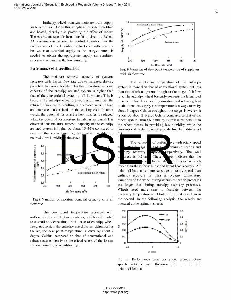
The variations of performance with rotary speed are plotted in Figs. 10 and 11 for dehumidification and enthalpy recovery purposes, respectively. The wall thickness is 0.2 mm. These figures indicate that the optimum rotary speed for air dehumidification is much lower than those for sensible and latent heat recovery. Air dehumidification is more sensitive to rotary speed than enthalpy recovery is. This is because temperature variations of the wheel during dehumidification processes are larger than during enthalpy recovery processes. Wheels need more time to fluctuate between the necessary temperature amplitude in the first case than in the second. In the following analysis, the wheels are operated at the optimum speeds.
Fig 10; Performance variations under various rotary speeds with a wall thickness 0.2 mm, for air dehumidification.
International Journal of Scientific & Engineering Research Volume 9, Issue 7, July-2018 ISSN 2229-5518
73
IJSER © 2018 http://www.ijser.org
IJSER

Fig.11 .Performance variations under various rotary speeds with a wall thickness 0.2 mm, for enthalpy recover
There exists an optimum rotary speed at which the efficiency reaches the climax. When a desiccant wheel rotates much faster than the optimum speed, the adsorption and regeneration processes are too short, which results in poor performance. On the other hand, when the rotary speed is lower than the optimum, the adsorption and regenerative processes are too long and wasting more energy in sensible heating/cooling rather than in sorption processes, and therefore are less effective [2].
Conclusion
An enthalpy wheel or desiccant wheel integrated air-conditioning system is studied. The desiccant wheel enhances the dehumidification of supply air thereby increasing scope for low humidity air-conditioning. The dew-point temperature of the supply air is lowered by about 2 degree Celsius and the COP is marginally lowered by about 5% compared to the conventional system. However, the system COP of enthalpy wheel based system is nearly double that of the reheat system.
Acknowledgement
We have taken efforts in this preparing paper. However, it would not have been possible without the kind support and help of Almighty God. We would like to extend our sincere thanks to many individuals. Special thanks to our Tutor Rajeesh Sir who provided all support and necessary information. Special thanks to Arjun Sir for his valuable support during preparation of the paper.
We are highly indebted to our college North Malabar Institute of Technology for their guidance and constant supervision as well as for providing necessary information regarding the subject and also for their support in completing the paper presentation. We would
like to express my gratitude towards my parents and my friends for their prayers and support.
Reference
[1.] L.Z. Zhang, J.L. Niu, Performance comparisons of desiccant wheels for air dehumidification and enthalpy recovery, Applied Thermal Engineering 22 (12)(2002) 1347–1367.
[2.] N. Subramanyam, M.P. Maiya, S. Srinivasa Murthy, Application of desiccant wheel to control humidity in air-conditioning systems, Applied Thermal Engineering 24 (2004) pp2777–2788.
[3.] FE Nia, D Van Paassen, M H Saidi Modeling and simulation of desiccant wheel for air conditioning Energy and buildings, 2006 – Elsevier
[4.] Enthalpy Wheel-Live Building livebuilding.queensu.ca/green features/enthalpy wheel.
[5.] Jim Shiminski, energy recovery wheels | what is an enthalpy wheel- 2012.
[6.] Jae-Weon Jeong, Stanley A. Mumma Practical
thermal performance correlations for molecular sieve and silica gel loaded enthalpy wheels; Applied Thermal Engineering 25 (2005) 719–740.
[7.] Mirela Radov ,Malali Mohammad, Jessica,Vasquez Alan Li, Brandon Lin – San Jose State University.
[8.] The Enthalpy Wheel vsgc.odu.edu/ACRPDesign Competition/.../2009/2009Environmental_thirdplace.pdf- 8 December 2008
[9.] Application & Design of Energy Recovery Wheels – Airxchange, Inc www.airxchange.com/resource-center-applicationdesign.htm
International Journal of Scientific & Engineering Research Volume 9, Issue 7, July-2018 ISSN 2229-5518
74
IJSER © 2018 http://www.ijser.org
IJSER

International Journal of Scientific & Engineering Research Volume 9, Issue 7, July-2018 ISSN 2229-5518
75
IJSER © 2018 http://www.ijser.org
IJSER