keyway splice box - meadow burkemeadowburke.com/elit/keyway spice box.pdf · astm a615 grade 60 and...
TRANSCRIPT

MeadowBurke®
A Concrete Reinforcement
Continuity System
Keyway Splice Box

2
MeadowBurke®Keyway Splice Box
www.MeadowBurke.com
ReinfoRCing Continuity SyStemS
The use of reinforcement continuity strip systems or ‘pull-out bar’ systems has
been widespread in European markets for over 30 years. It is becoming a very
common method of ensuring continuity of reinforcement across construction
joints in concrete. The system design includes lapping reinforcement to provide
a splice and connection.
Meadow Burke has been involved in manufacturing of the Keyway Splice Box
since it’s original introduction to the US market in 1992. The Keyway Splice Box
system is a safe and cost effective reinforcement method that also provides
time and labor savings in many applications. The system is custom made to
meet each engineers reinforcement detail, eliminating unnecessary labor on site.
The Keyway Splice Box system consists of unique, high yield reinforcing steel,
housed in a galvanized steel carrier unit. The unit ends are sealed to prevent
leakage. The reinforcement used is available in #4, #5 or #6 and is equal to
ASTM A615 Grade 60 and meets ACI 318-11. The system is assembled in a
controlled factory environment in order to provide the quality demanded from
a harsh construction environment.
The units are used on site by nailing to the formwork or wire tied to the main
reinforcement, prior to a concrete pour. After concrete is poured and the form-
work is removed the lid is easily removed to expose ready to use lap splice bars.
The bars are bent out the case to provide an easy lap splice to the main
reinforcing steel and subsequent concrete pours.
The case design offers an efficient key and requires no further joint preparation.
The dovetail shaped casing ensures the product remains embedded in the
structure when removing the formwork. The case remains in the joint and is
filled with concrete on the subsequent concrete pour.
Applications:Keyway Splice Box Systems may be used in most concrete construction joints.
The systems are being utilized in high rise residential , hotels, office towers,
hospitals, prisons, solar energy, wind towers, water treatment, concrete
pavement, bridge construction, and many other types of projects. Typical joint
applications include.
• floor slabs • walls
• stairwells • beams
• corbels • diaphragm walls
• jump forms • brick support ledges
• precast elements • tilt-up panels
• bridge decks • concrete paving/slab on grade

3
MeadowBurke®Keyway Splice Box
www.MeadowBurke.com
the BenefitS of ouR Solution
Use of the Keyway Splice Box system offers many benefits over conventional joint construction. This contributes to the acceleration of the construction process.Some of the advantages of using the Keyway Splice Box Systems:
SPEED SAFETY QUALITY COSTKeyway Splice Box units are easyto use and quickly nailed to form-work or tied to the main reinforce-ment.
Eliminates the need to drill form-work for rebar.
Formwork designs can be simpli-fied and complicated constructionjoint designs reduced.
Climbing formwork systems canbe easily used.
Easy to use, the system requireslittle onsite training in order tocarry out installation.
The Reinforcing Bars are housedin a steel case until ready for use.
The Keyway Splice Box eliminatesprotruding bars that potentiallycause injury and improves avail-able work space.
Prepositioned bars ensure precisealignment, assures full load trans-fer, increases joint strength andlimits the concrete shrinkagebetween concrete placements.
A perforated casing allows freeairflow, assisting removal of en-trapped air, especially where highpour heights are being achieved.
Fabricated in a controlled manu-facturing environment to ensurethe highest quality and dimen-sional integrity.
The reinforcement bars remain pro-tected and clean from damageuntil required for use.
Formwork systems do not need tobe drilled, damaged or repairedwhen using the Keyway Splice Boxsystem, thus improving the life ofcycle formwork.
The Keyway Splice Box is extremelyeasy to use and can be installedwithout specialized training.
Simplifies formwork designs andallows larger concrete pour.
Eases rebar and formwork place-ment, improving your productivity.

4
MeadowBurke®Keyway Splice Box
www.MeadowBurke.com
SyStem ComponentS
Keyway Splice Boxes are available with either a single or double row
of dowel bars, straight dowels, hooks, stirrups and lap splices. They
are custom fabricated to meet exact specifications and job design
requirements.
STEEL CASE The Keyway Splice Box cases are manufactured from galvanized mild
steel rolled to precise dimensions. The cases are perforated on the
larger face to provide an excellent bond to the first concrete pour and
provide an efficient key for the subsequent pour. A wide range of case
sizes are available to suit the rebar detail requirement.
STEEL LID The Keyway Splice Box system is fitted with a rigid metal lid that
allows easy removal once required.
END CAP SEAL Keyway Splice Box cases are fitted with two easily removed poly-
styrene end caps that prohibit concrete from entering the casing. End
cap seals are suitable for recycling once removed.
Keyway Splice Box Systems feature the exclusive use of the dovetail
steel keyway. This keyway produces a locked joint which results in
increased full out strength and a much greater resistance to shear
at the joint.
COMMON BOX DESIGN TYPESBox designs have been simplified to meet a wide array of reinforce-
ment variations. Common Casing Types are:
• 60S/100S
• 160D
• 160DD
Box TypeStandardWidth
StandardDepth
StandardLength
MinimumLength
MaximmumLength
60S
100S
160D
160DD
2.5"
3.5"
6"
6"
1.5"
1.5"
1.5"
1.5"
48"
48"
48"
48"
24"
24"
24"
24"
96"
96"
96"
96"
Each project has its own unique requirements. The dimensions provided areeasily adjusted to suit specific needs.
Type 160DD
Type 160D
Type 60S & 100S
End Cap Seal
Steel Lid
Steel Case
5
MeadowBurke®Keyway Splice Box
www.MeadowBurke.com
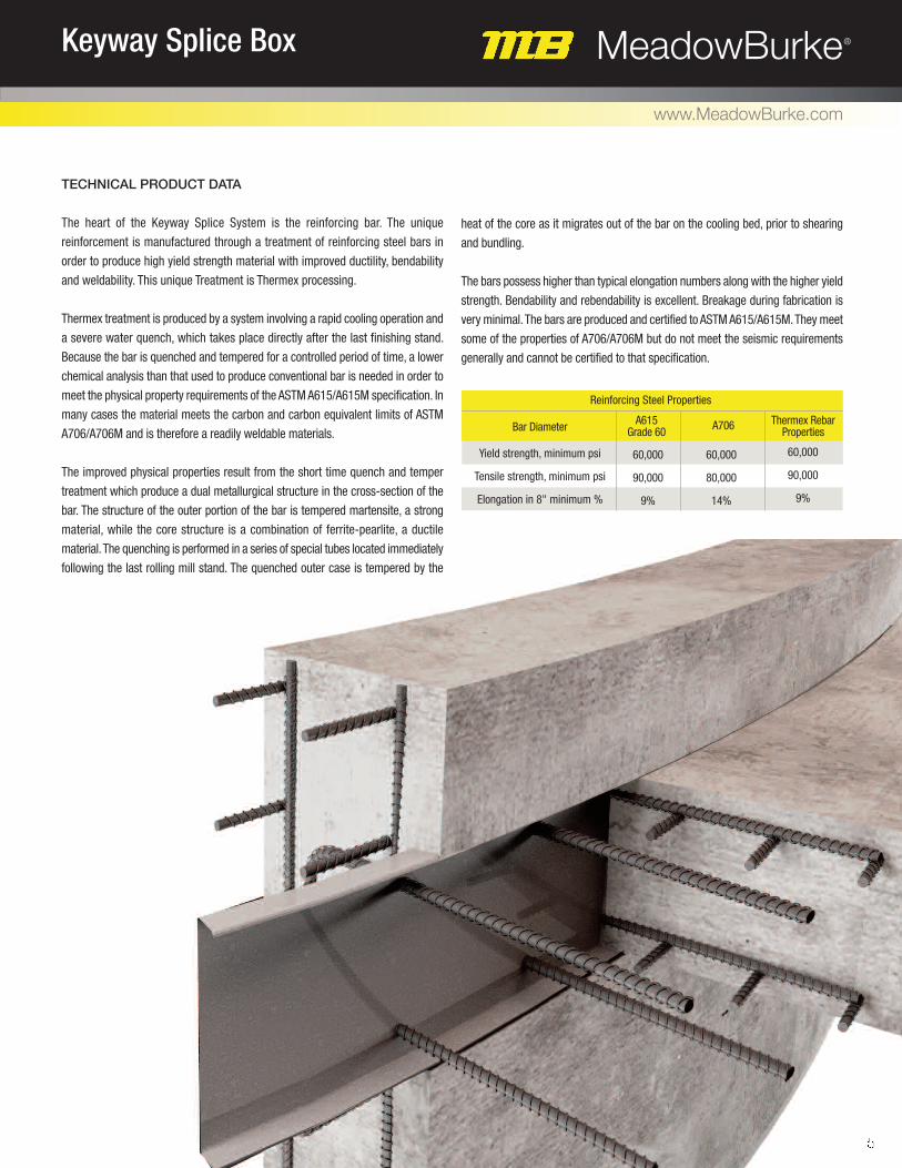
teChniCAl pRoduCt dAtA
The heart of the Keyway Splice System is the reinforcing bar. The unique
reinforcement is manufactured through a treatment of reinforcing steel bars in
order to produce high yield strength material with improved ductility, bendability
and weldability. This unique Treatment is Thermex processing.
Thermex treatment is produced by a system involving a rapid cooling operation and
a severe water quench, which takes place directly after the last finishing stand.
Because the bar is quenched and tempered for a controlled period of time, a lower
chemical analysis than that used to produce conventional bar is needed in order to
meet the physical property requirements of the ASTM A615/A615M specification. In
many cases the material meets the carbon and carbon equivalent limits of ASTM
A706/A706M and is therefore a readily weldable materials.
The improved physical properties result from the short time quench and temper
treatment which produce a dual metallurgical structure in the cross-section of the
bar. The structure of the outer portion of the bar is tempered martensite, a strong
material, while the core structure is a combination of ferrite-pearlite, a ductile
material. The quenching is performed in a series of special tubes located immediately
following the last rolling mill stand. The quenched outer case is tempered by the
heat of the core as it migrates out of the bar on the cooling bed, prior to shearing
and bundling.
The bars possess higher than typical elongation numbers along with the higher yield
strength. Bendability and rebendability is excellent. Breakage during fabrication is
very minimal. The bars are produced and certified to ASTM A615/A615M. They meet
some of the properties of A706/A706M but do not meet the seismic requirements
generally and cannot be certified to that specification.
Bar Diameter A615 Grade 60 A706 Thermex Rebar
Properties
Reinforcing Steel Properties
Yield strength, minimum psi
Tensile strength, minimum psi
Elongation in 8" minimum %
60,000
90,000
9%
60,000
80,000
14%
60,000
90,000
9%
6
MeadowBurke®Keyway Splice Box
www.MeadowBurke.com
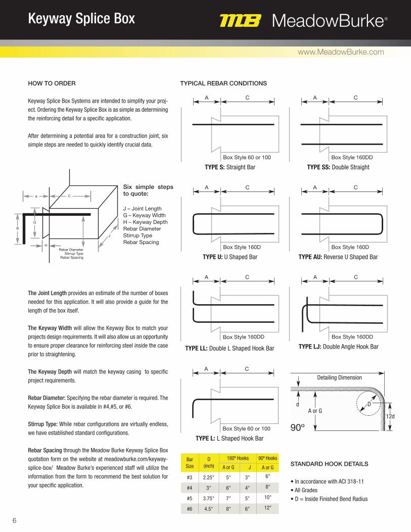
A C
Box Style 60 or 100
TYPE S: Straight Bar TYPE SS: Double Straight
A C
Box Style 160DD
A C
Box Style 60 or 100
TYPE L: L Shaped Hook Bar
A C
Box Style 160DD
TYPE LJ: Double Angle Hook BarTYPE LL: Double L Shaped Hook Bar
A C
Box Style 160DD
A C
Box Style 160D
TYPE U: U Shaped Bar TYPE AU: Reverse U Shaped Bar
A C
Box Style 160D
typiCAl ReBAR ConditionS
StAndARd hook detAilS
• In accordance with ACI 318-11
• All Grades
• D = Inside Finished Bend Radius
Bar Size
D(inch) A or G J A or G
180º Hooks 90º Hooks
#3
#4
#5
#6
2.25"
3"
3.75"
4.5"
5"
6"
7"
8"
3"
4"
5"
6"
6"
8"
10"
12"
dA or G
Detailing Dimension
D
12d
90º
how to oRdeR
Keyway Splice Box Systems are intended to simplify your proj-
ect. Ordering the Keyway Splice Box is as simple as determining
the reinforcing detail for a specific application.
After determining a potential area for a construction joint, six
simple steps are needed to quickly identify crucial data.
The Joint Length provides an estimate of the number of boxes
needed for this application. It will also provide a guide for the
length of the box itself.
The Keyway Width will allow the Keyway Box to match your
projects design requirements. It will also allow us an opportunity
to ensure proper clearance for reinforcing steel inside the case
prior to straightening.
The Keyway Depth will match the keyway casing to specific
project requirements.
Rebar Diameter: Specifying the rebar diameter is required. The
Keyway Splice Box is available in #4,#5, or #6.
Stirrup Type: While rebar configurations are virtually endless,
we have established standard configurations.
Rebar Spacing through the Meadow Burke Keyway Splice Box
quotation form on the website at meadowburke.com/keyway-
splice-box/ Meadow Burke’s experienced staff will utilize the
information from the form to recommend the best solution for
your specific application.
Rebar DiameterStirrup Type
Rebar Spacing
H
G
B
CA
J
Six simple stepsto quote:
J – Joint LengthG – Keyway WidthH – Keyway DepthRebar DiameterStirrup TypeRebar Spacing

7
MeadowBurke®Keyway Splice Box
www.MeadowBurke.com
ReBAR StRAightening pRoCeduRe
1. After the disposable cover is removed, the bars are to be easily pulled out by
hand at a maximum of 20º from the Keyway box.
2. A hickey bar (cheater bar) of a diameter just large enough to slide over the
pre-bent bar is to be used to finish the procedure.
3. Slide the hickey bar as far up the bar as possible and rebend the bar
approximately another 25º–30º. Repeat this procedure 2 – 3 times more
until the bar is exactly straight. DO NOT REBEND the pre-bent bars in
one motion.
4. Do not heat the bars for rebending. We also do not recommend rebending the
bars in the field more than once.
inStAllAtion
The Keyway is easily installed in the field by nailing it directly to the form face, this will ensure linearity and proper dowel bar spacing, which reduces
installation and job site labor costs.
Attach the Keyway Box by nailing through the casing
to the formwork or securely tie the projecting rein-
forcing bars to existing reinforcement. The Box should
be firmly secured and tight against the formwork to
avoid displacement during concrete placement.
Once the formwork is removed, the steel cover will
be exposed. Remove the steel cover to expose the
pre-bent reinforcing steel.
Straighten the bars using a hickey bar (cheater bar)
that is slightly larger than the rebar being straight-
ened. The bars should be straightened only once ac-
cording to the procedure highlighted below. Care
should be taken to avoid damage to adjacent con-
crete, See ‘Rebar Straightening’ below for additional
information.
2 31
MeadowBurke®
tAmpA
2835 Overpass Rd.Tampa, FL 33619(877) 518-7665
engineeRing
(866) 730-2904
ARizonA
phoenix
501 N. 37th Dr.Suite 106-109Phoenix, AZ 85009(602) 455-0717(800) 817-9698FAX: (602) 455-0719
CAlifoRniA
AnAheim
3611 East La Palma Ave.Suite A Anaheim, CA 92806 (714) 632-6651 (800) 804-6565 FAX: (714) 632-9412
floRidA
tAmpA
2835 Overpass Rd.Tampa, FL 33619(813) 248-1945(800) 282-7213FAX: (877) 568-8296
geoRgiA
AtlAntA
3080 N. Lanier ParkwayDecatur, GA 30034(404) 378-3175(800) 241-5662FAX: (404) 373-1804
new JeRSey
pAliSAdeS pARk
269 Commercial Ave.Palisades Park, NJ 07650(201) 242-8989(800) 207-7778FAX: (201) 242-8860
noRth CARolinA
ChARlotte
3401-A Woodpark Blvd.Charlotte NC 28206(704) 376-9192(800) 376-9192FAX: (704) 376-6939
ohio
CinCinnAti
513) 942-0268
(866) 773-0536
fAx: (877) 311-0452
oRegon
poRtlAnd
155 SE Hazel Dell WayCanby, OR 97013(888) 232-9991FAX: (503) 266-8934
texAS
SAn Antonio
8521 FM 1976Converse TX 78109(210) 658-4671(800) 323-6896FAX: (210) 658-8312
texAS
ft. woRth
7000 Will Rogers Blvd. Ft. Worth, TX 76140(817) 293-9641(800) 993-9641FAX: (817) 293-8081
viRginiA
wAShington, dC
11001 Houser Dr., Unit 25Fredericksburg, VA 22408(540) 376-3287(800) 550-0060FAX: (540) 898-5209
wAShington
AuBuRn
3416 B Street, Suite BAuburn, WA 98001(877) 289-2113FAX: (877) 439-1965
SeRviCe & diStRiBution CenteRS CoRpoRAte
MB0416
Innovating Concrete Constructionwww.MeadowBurke.com