keystone architecture multicore navigator (rev. h) · keystone architecture multicore navigator...
TRANSCRIPT

KeyStone ArchitectureMulticore Navigator
User's Guide
Literature Number: SPRUGR9HNovember 2010–Revised April 2015
Contents
Preface....................................................................................................................................... 111 Introduction ....................................................................................................................... 13
1.1 Terminology Used in This Document .................................................................................... 141.2 KeyStone I Features ....................................................................................................... 141.3 KeyStone I Functional Block Diagram ................................................................................... 151.4 KeyStone II Changes to QMSS .......................................................................................... 161.5 KeyStone II QMSS Modes of Use ....................................................................................... 16
1.5.1 Shared Mode....................................................................................................... 171.5.2 Split Mode .......................................................................................................... 17
1.6 Overview..................................................................................................................... 181.7 Queue Manager ............................................................................................................ 181.8 Packet DMA (PKTDMA) ................................................................................................... 181.9 Navigator Cloud ............................................................................................................ 181.10 Virtualization ................................................................................................................ 191.11 ARM-DSP Shared Use .................................................................................................... 191.12 PDSP Firmware ............................................................................................................ 19
2 Operational Concepts ......................................................................................................... 212.1 Packets ...................................................................................................................... 222.2 Queues ...................................................................................................................... 22
2.2.1 Packet Queuing.................................................................................................... 222.2.2 Packet De-queuing................................................................................................ 222.2.3 Queue Proxy ....................................................................................................... 22
2.3 Queue Types................................................................................................................ 222.3.1 Transmit Queues .................................................................................................. 222.3.2 Transmit Completion Queues.................................................................................... 232.3.3 Receive Queues................................................................................................... 232.3.4 Free Descriptor Queues (FDQ).................................................................................. 23
2.3.4.1 Host Packet Free Descriptors ............................................................................. 232.3.4.2 Monolithic Free Descriptors................................................................................ 23
2.3.5 Queue Pend Queues ............................................................................................. 232.4 Descriptors .................................................................................................................. 23
2.4.1 Host Packet ........................................................................................................ 232.4.2 Host Buffer ......................................................................................................... 242.4.3 Monolithic Packet.................................................................................................. 24
2.5 Packet DMA................................................................................................................. 252.5.1 Channels ........................................................................................................... 252.5.2 RX Flows ........................................................................................................... 25
2.6 Packet Transmission Overview........................................................................................... 252.7 Packet Reception Overview............................................................................................... 262.8 ARM Endianess ............................................................................................................ 28
3 Descriptor Layouts ............................................................................................................. 303.1 Host Packet Descriptor .................................................................................................... 313.2 Host Buffer Descriptor ..................................................................................................... 353.3 Monolithic Descriptor....................................................................................................... 37
2 Contents SPRUGR9H–November 2010–Revised April 2015Submit Documentation Feedback
Copyright © 2010–2015, Texas Instruments Incorporated

www.ti.com
4 Registers........................................................................................................................... 424.1 Queue Manager ............................................................................................................ 43
4.1.1 Queue Configuration Region .................................................................................... 434.1.1.1 Revision Register (0x00000000) .......................................................................... 434.1.1.2 Queue Diversion Register (0x00000008) ................................................................ 444.1.1.3 Linking RAM Region 0 Base Address Register (0x0000000C) ....................................... 454.1.1.4 Linking RAM Region 0 Size Register (0x00000010) ................................................... 464.1.1.5 Linking RAM Region 1 Base Address Register (0x00000014) ....................................... 474.1.1.6 Free Descriptor/Buffer Starvation Count Register N (0x00000020 + N×4).......................... 48
4.1.2 Queue Status RAM ............................................................................................... 494.1.3 Descriptor Memory Setup Region............................................................................... 50
4.1.3.1 Memory Region R Base Address Register (0x00000000 + 16×R) ................................... 504.1.3.2 Memory Region R Start Index Register (0x00000004 + 16×R)....................................... 514.1.3.3 Memory Region R Descriptor Setup Register (0x00000008 + 16×R)................................ 52
4.1.4 Queue Management/Queue Proxy Regions ................................................................... 534.1.4.1 Queue N Register A (0x00000000 + 16×N) ............................................................. 544.1.4.2 Queue N Register B (0x00000004 + 16×N) ............................................................. 554.1.4.3 Queue N Register C (0x00000008 + 16×N) ............................................................. 564.1.4.4 Queue N Register D (0x0000000C + 16×N) ............................................................ 57
4.1.5 Queue Peek Region .............................................................................................. 584.1.5.1 Queue N Status and Configuration Register A (0x00000000 + 16×N) .............................. 584.1.5.2 Queue N Status and Configuration Register B (0x00000004 + 16×N) .............................. 594.1.5.3 Queue N Status and Configuration Register C (0x00000008 + 16×N) .............................. 604.1.5.4 Queue N Status and Configuration Register D (0x0000000C + 16×N).............................. 61
4.2 Packet DMA................................................................................................................. 624.2.1 Global Control Registers Region ................................................................................ 62
4.2.1.1 Revision Register (0x00) ................................................................................... 624.2.1.2 Performance Control Register (0x04) .................................................................... 634.2.1.3 Emulation Control Register (0x08)........................................................................ 644.2.1.4 Priority Control Register (0x0C) ........................................................................... 654.2.1.5 QMn Base Address Register (0x10, 0x14, 0x18, 0x1c)................................................ 66
4.2.2 TX DMA Channel Configuration Region ....................................................................... 674.2.2.1 TX Channel N Global Configuration Register A (0x000 + 32×N)..................................... 684.2.2.2 TX Channel N Global Configuration Register B (0x004 + 32×N)..................................... 69
4.2.3 RX DMA Channel Configuration Region ....................................................................... 704.2.3.1 RX Channel N Global Configuration Register A (0x000 + 32×N)..................................... 70
4.2.4 RX DMA Flow Configuration Region............................................................................ 714.2.4.1 RX Flow N Configuration Register A (0x000 + 32×N) ................................................. 724.2.4.2 RX Flow N Configuration Register B (0x004 + 32×N) ................................................. 744.2.4.3 RX Flow N Configuration Register C (0x008 + 32×N) ................................................. 754.2.4.4 RX Flow N Configuration Register D (0x00C + 32×N) ................................................. 774.2.4.5 RX Flow N Configuration Register E (0x010 + 32×N) ................................................. 784.2.4.6 RX Flow N Configuration Register F (0x014 + 32×N).................................................. 794.2.4.7 RX Flow N Configuration Register G (0x018 + 32×N) ................................................. 804.2.4.8 RX Flow N Configuration Register H (0x01C + 32×N) ................................................. 81
4.2.5 TX Scheduler Configuration Region ............................................................................ 824.2.5.1 TX Channel N Scheduler Configuration Register (0x000 + 4×N)..................................... 82
4.3 QMSS PDSPs .............................................................................................................. 834.3.1 Descriptor Accumulation Firmware ............................................................................. 84
4.3.1.1 Command Buffer Interface................................................................................. 844.3.1.2 Global Timer Command Interface ........................................................................ 864.3.1.3 Reclamation Queue Command Interface ................................................................ 874.3.1.4 Queue Diversion Command Interface.................................................................... 87
3SPRUGR9H–November 2010–Revised April 2015 ContentsSubmit Documentation Feedback
Copyright © 2010–2015, Texas Instruments Incorporated
www.ti.com
4.3.2 Quality of Service Firmware ..................................................................................... 874.3.2.1 QoS Algorithms ............................................................................................. 884.3.2.2 Command Buffer Interface................................................................................. 914.3.2.3 QoS Firmware Commands ................................................................................ 924.3.2.4 QoS Queue Record......................................................................................... 924.3.2.5 QoS Cluster Record ........................................................................................ 934.3.2.6 RR-Mode QoS Cluster Record ............................................................................ 944.3.2.7 SRIO Queue Monitoring ................................................................................... 95
4.3.3 Open Event Machine Firmware ................................................................................. 964.3.4 Interrupt Operation ................................................................................................ 96
4.3.4.1 Interrupt Handshaking ...................................................................................... 964.3.4.2 Interrupt Processing ........................................................................................ 974.3.4.3 Interrupt Generation ........................................................................................ 974.3.4.4 Stall Avoidance .............................................................................................. 98
4.3.5 QMSS PDSP Registers .......................................................................................... 994.3.5.1 Control Register (0x00000000) .......................................................................... 1004.3.5.2 Status Register (0x00000004) ........................................................................... 1014.3.5.3 Cycle Count Register (0x0000000C) ................................................................... 1024.3.5.4 Stall Count Register (0x00000010) ..................................................................... 103
4.4 QMSS Interrupt Distributor .............................................................................................. 1044.4.1 INTD Register Region........................................................................................... 104
4.4.1.1 Revision Register (0x00000000) ........................................................................ 1054.4.1.2 End Of Interrupt (EOI) Register (0x00000010) ........................................................ 1064.4.1.3 Status Register 0 (0x00000200)......................................................................... 1074.4.1.4 Status Register 1 (0x00000204)......................................................................... 1084.4.1.5 Status Register 2(0x00000208).......................................................................... 1094.4.1.6 Status Register 3(0x0000020c).......................................................................... 1104.4.1.7 Status Register 4 (0x00000210)......................................................................... 1114.4.1.8 Status Clear Register 0 (0x00000280) ................................................................. 1124.4.1.9 Status Clear Register 1 (0x00000284) ................................................................. 1134.4.1.10 Status Clear Register 4 (0x00000290) ................................................................. 1144.4.1.11 Interrupt N Count Register (0x00000300 + 4xN) ...................................................... 115
5 Mapping Information ......................................................................................................... 1175.1 Queue Maps............................................................................................................... 1185.2 Interrupt Maps ............................................................................................................. 120
5.2.1 KeyStone I TCI661x, C6670, C665x devices ................................................................ 1205.2.2 KeyStone I TCI660x, C667x devices.......................................................................... 1215.2.3 KeyStone II devices ............................................................................................. 122
5.3 Memory Maps ............................................................................................................. 1235.3.1 QMSS Register Memory Map .................................................................................. 1235.3.2 KeyStone I PKTDMA Register Memory Map................................................................. 1245.3.3 KeyStone II PKTDMA Register Memory Map................................................................ 124
5.4 Packet DMA Channel Map .............................................................................................. 125
6 Programming Information .................................................................................................. 1276.1 Programming Considerations ........................................................................................... 128
6.1.1 System Planning ................................................................................................. 1286.1.2 Notification of Completed Work ................................................................................ 129
6.2 Example Code............................................................................................................. 1296.2.1 QMSS Initialization .............................................................................................. 1306.2.2 PKTDMA Initialization ........................................................................................... 1326.2.3 Normal Infrastructure DMA with Accumulation .............................................................. 1336.2.4 Bypass Infrastructure notification with Accumulation ....................................................... 1346.2.5 Channel Teardown .............................................................................................. 135
4 Contents SPRUGR9H–November 2010–Revised April 2015Submit Documentation Feedback
Copyright © 2010–2015, Texas Instruments Incorporated

www.ti.com
6.3 Programming Overrides.................................................................................................. 1356.4 Programming Errors ...................................................................................................... 1356.5 Questions and Answers.................................................................................................. 137
A Example Code Utility Functions.......................................................................................... 142B Example Code Types ........................................................................................................ 153C Example Code Addresses .................................................................................................. 159
C.1 KeyStone I Addresses:................................................................................................... 159C.2 KeyStone II Addresses: .................................................................................................. 161
Revision History ........................................................................................................................ 164Revision History ........................................................................................................................ 164
5SPRUGR9H–November 2010–Revised April 2015 ContentsSubmit Documentation Feedback
Copyright © 2010–2015, Texas Instruments Incorporated

www.ti.com
List of Figures1-1. Multicore Navigator Block Diagram (KeyStone I) ...................................................................... 151-2. Queue Manager Sub System for KeyStone II .......................................................................... 161-3. Queue Manager Linking RAM — Shared Mode for KeyStone II..................................................... 171-4. Queue Manager Linking RAM — Split Mode for KeyStone II ........................................................ 172-1. Packet Queuing Data Structure Diagram ............................................................................... 242-2. Packet Transmit Operation................................................................................................ 262-3. Packet Receive Operation ............................................................................................... 274-1. Revision Register (0x00000000) ......................................................................................... 434-2. Queue Diversion Register (0x00000008) ............................................................................... 444-3. Linking RAM Region 0 Base Address Register (0x0000000C) ...................................................... 454-4. Linking RAM Region 0 Size Register (0x00000010) .................................................................. 464-5. Linking RAM Region 1 Base Address Register (0x00000014)....................................................... 474-6. Free Descriptor/Buffer Starvation Count Register N (0x00000020 + N×4) ......................................... 484-7. Queue Threshold Status Word N (0x00000000 - 0x000003FC) ..................................................... 494-8. Memory Region R Base Address Register (0x00000000 + 16×R) .................................................. 504-9. Memory Region R Start Index Register (0x00000004 + 16×R) ...................................................... 514-10. Memory Region R Descriptor Setup Register (0x00000008 + 16×R) ............................................... 524-11. Queue N Register A (0x00000000 + 16×N) ............................................................................ 544-12. Queue N Register B (0x00000004 + 16×N) ............................................................................ 554-13. Queue N Register C (0x00000008 + 16×N) ............................................................................ 564-14. Queue N Register D (0x0000000C + 16×N)............................................................................ 574-15. Queue N Status and Configuration Register A (0x00000000 + 16×N).............................................. 584-16. Queue N Status and Configuration Register B (0x00000004 + 16×N).............................................. 594-17. Queue N Status and Configuration Register C (0x00000008 + 16×N).............................................. 604-18. Queue N Status and Configuration Register D (0x0000000C + 16×N) ............................................. 614-19. Revision Register (0x00) .................................................................................................. 624-20. Performance Control Register (0x04).................................................................................... 634-21. Emulation Control Register (0x08) ....................................................................................... 644-22. Priority Control Register (0x0C) .......................................................................................... 654-23. QMn Base Address Register (0x04) ..................................................................................... 664-24. TX Channel N Global Configuration Register A (0x000 + 32×N) .................................................... 684-25. TX Channel N Global Configuration Register B (0x004 + 32×N) .................................................... 694-26. RX Channel N Global Configuration Register A (0x000 + 32×N).................................................... 704-27. RX Flow N Configuration Register A (0x000 + 32×N)................................................................. 724-28. RX Flow N Configuration Register B (0x004 + 32×N) ................................................................ 744-29. RX Flow N Configuration Register C (0x008 + 32×N)................................................................. 754-30. RX Flow N Configuration Register D (0x00C + 32×N) ............................................................... 774-31. RX Flow N Configuration Register E (0x010 + 32×N) ................................................................ 784-32. RX Flow N Configuration Register F (0x014 + 32×N) ................................................................. 794-33. RX Flow N Configuration Register G (0x018 + 32×N) ................................................................ 804-34. RX Flow N Configuration Register H (0x01C + 32×N) ................................................................ 814-35. TX Channel N Scheduler Configuration Register (0x000 + 4×N) .................................................... 824-36. Handshaking During Processing of Descriptor Lists................................................................... 974-37. Control Register (0x00000000) ......................................................................................... 1004-38. Status Register (0x00000004) .......................................................................................... 1014-39. Cycle Count Register (0x0000000c) ................................................................................... 1024-40. Stall Count Register (0x00000010)..................................................................................... 103
6 List of Figures SPRUGR9H–November 2010–Revised April 2015Submit Documentation Feedback
Copyright © 2010–2015, Texas Instruments Incorporated
www.ti.com
4-41. Revision Register (0x00000000)........................................................................................ 1054-42. EOI Register (0x00000010) ............................................................................................. 1064-43. Status Register 0 (0x00000200) ........................................................................................ 1074-44. Status Register 1 (0x00000204) ........................................................................................ 1084-45. Status Register 2 (0x00000208) ........................................................................................ 1094-46. Status Register 3 (0x0000020c) ........................................................................................ 1104-47. Status Register 4 (0x00000210) ........................................................................................ 1114-48. Status Clear Register 0 (0x00000280)................................................................................. 1124-49. Status Clear Register 1 (0x00000284)................................................................................. 1134-50. Status Clear Register 4 (0x00000290)................................................................................. 1144-51. Int N Count Register (0x00000300 + 4xN) ............................................................................ 115
7SPRUGR9H–November 2010–Revised April 2015 List of FiguresSubmit Documentation Feedback
Copyright © 2010–2015, Texas Instruments Incorporated
www.ti.com
List of Tables1-1. Terminology ................................................................................................................ 143-1. Host Packet Descriptor Layout ........................................................................................... 313-2. Host Packet Descriptor Packet Information Word 0 (PD Word 0) .................................................. 323-3. Host Packet Descriptor Packet Information Word 1 (PD Word 1) .................................................. 323-4. Host Packet Descriptor Packet Information Word 2 (PD Word 2) .................................................. 323-5. Host Packet Descriptor Buffer 0 Info Word 0 (PD Word 3) .......................................................... 333-6. Host Packet Descriptor Buffer 0 Info Word 1 (PD Word 4) .......................................................... 333-7. Host Packet Descriptor Linking Word (PD Word 5) ................................................................... 333-8. Host Packet Descriptor Original Buffer Info Word 0 (PD Word 6) .................................................. 343-9. Host Packet Descriptor Original Buffer Info Word 1 (PD Word 7) .................................................. 343-10. Host Packet Descriptor Extended Packet Info Block Word 0 (Optional) ........................................... 343-11. Host Packet Descriptor Extended Packet Info Block Word 1 (Optional) ........................................... 343-12. Host Packet Descriptor Extended Packet Info Block Word 2 (Optional) ........................................... 343-13. Host Packet Descriptor Extended Packet Info Block Word 3 (Optional) ........................................... 353-14. Host Packet Descriptor Protocol Specific Word N (Optional) ........................................................ 353-15. Host Buffer Descriptor Layout ............................................................................................ 353-16. Host Buffer Descriptor Reserved Word 0 (BD Word 0) .............................................................. 363-17. Host Buffer Descriptor Reserved Word 1 (BD Word 1) .............................................................. 363-18. Host Buffer Descriptor Buffer Reclamation Info (BD Word 2) ....................................................... 363-19. Host Buffer Descriptor Buffer N Info Word 0 (BD Word 3)............................................................ 363-20. Host Buffer Descriptor Buffer N Info Word 1 (BD Word 4) ........................................................... 363-21. Host Buffer Descriptor Linking Word (BD Word 5) .................................................................... 363-22. Host Buffer Descriptor Original Buffer Info Word 0 (BD Word 6) ................................................... 373-23. Host Buffer Descriptor Original Buffer Info Word 1 (BD Word 7) ................................................... 373-24. Monolithic Packet Descriptor Layout..................................................................................... 383-25. Monolithic Packet Descriptor Word 0 ................................................................................... 383-26. Monolithic Packet Descriptor Word 1 ................................................................................... 393-27. Monolithic Packet Descriptor Word 2 ................................................................................... 393-28. Monolithic Extended Packet NULL Word (Optional) .................................................................. 393-29. Monolithic Extended Packet Info Word 0 (Optional) .................................................................. 403-30. Monolithic Extended Packet Info Word 1 (Optional) .................................................................. 403-31. Monolithic Extended Packet Info Word 2 (Optional) .................................................................. 403-32. Monolithic Extended Packet Info Word 3 (Optional) .................................................................. 403-33. Monolithic Packet Descriptor Protocol Specific Word M (Optional) ................................................. 403-34. Monolithic Packet Descriptor Payload Data Words 0-N .............................................................. 404-1. Queue Configuration Region Registers ................................................................................. 434-2. Revision Register Field Descriptions ................................................................................... 434-3. Queue Diversion Register Field Descriptions .......................................................................... 444-4. Linking RAM Region 0 Base Address Register Field Descriptions ................................................. 454-5. Linking RAM Region 0 Size Register Field Descriptions ............................................................. 464-6. Linking RAM Region 1 Base Address Register Field Descriptions ................................................. 474-7. Free Descriptor/Buffer Starvation Count Register N Field Descriptions ........................................... 484-8. Queue Threshold Status Word N Field Descriptions ................................................................. 494-9. Descriptor Memory Setup Region Registers............................................................................ 504-10. Memory Region R Base Address Register Field Descriptions ...................................................... 504-11. Memory Region R Start Index Register Field Descriptions .......................................................... 514-12. Memory Region R Descriptor Setup Register Field Descriptions ................................................... 52
8 List of Tables SPRUGR9H–November 2010–Revised April 2015Submit Documentation Feedback
Copyright © 2010–2015, Texas Instruments Incorporated
www.ti.com
4-13. Queue Management/Proxy Region Registers .......................................................................... 534-14. Queue N Register A Field Descriptions ................................................................................ 544-15. Queue N Register B Field Descriptions ................................................................................ 554-16. Queue N Register C Field Descriptions ................................................................................ 564-17. Queue N Register D Field Descriptions ................................................................................ 574-18. Queue Peek Region Registers ........................................................................................... 584-19. Queue N Status and Configuration Register A Field Descriptions .................................................. 584-20. Queue N Status and Configuration Register B Field Descriptions .................................................. 594-21. Queue N Status and Configuration Register C Field Descriptions .................................................. 604-22. Queue N Status and Configuration Register D Field Descriptions .................................................. 614-23. PKTDMA Global Control Region Registers ............................................................................. 624-24. Revision Register Field Descriptions ................................................................................... 624-25. Performance Control Register Field Descriptions ..................................................................... 634-26. Emulation Control Register Field Descriptions ........................................................................ 644-27. Priority Control Register Field Descriptions ............................................................................ 654-28. Qmn Base Address Register Field Descriptions ...................................................................... 664-29. TX DMA Channel Config Region Registers ............................................................................ 674-30. TX Channel N Global Configuration Register A Field Descriptions ................................................. 684-31. TX Channel N Global Configuration Register B Field Descriptions ................................................. 694-32. RX DMA Channel Config Region Registers ............................................................................ 704-33. RX Channel N Global Configuration Register A Field Descriptions ................................................ 704-34. RX DMA Flow Config Region Registers................................................................................. 714-35. RX Flow N Configuration Register A Field Descriptions ............................................................. 724-36. RX Flow N Configuration Register B Field Descriptions ............................................................. 744-37. RX Flow N Configuration Register C Field Descriptions ............................................................. 754-38. RX Flow N Configuration Register D Field Descriptions ............................................................. 774-39. RX Flow N Configuration Register E Field Descriptions ............................................................. 784-40. RX Flow N Configuration Register F Field Descriptions ............................................................. 794-41. RX Flow N Configuration Register G Field Descriptions ............................................................. 804-42. RX Flow N Configuration Register H Field Descriptions ............................................................. 814-43. TX DMA Scheduler Configuration Region Registers .................................................................. 824-44. TX Channel N Scheduler Configuration Register Field Descriptions ............................................... 824-45. Possible PDSP Firmware Loading ....................................................................................... 834-46. Recommended PDSP Firmware Loading ............................................................................... 834-47. Command Buffer Format ................................................................................................. 844-48. Command Buffer Field Descriptions .................................................................................... 854-49. Configuration Byte Subfields ............................................................................................. 864-50. Global Timer Command Format ......................................................................................... 864-51. Reclamation Queue Command Format ................................................................................ 874-52. Queue Diversion Command Format .................................................................................... 874-53. QoS Firmware Memory Organization.................................................................................... 884-54. Destination Congestion and Credit Scaling ............................................................................ 904-55. Command Buffer Interface ............................................................................................... 914-56. Command Buffer Field Descriptions .................................................................................... 914-57. QoS Queue Record ....................................................................................................... 924-58. QoS Queue Field Descriptions .......................................................................................... 924-59. QoS Cluster Record ....................................................................................................... 934-60. QoS Cluster Field Descriptions .......................................................................................... 934-61. QoS Cluster Record 7 .................................................................................................... 94
9SPRUGR9H–November 2010–Revised April 2015 List of TablesSubmit Documentation Feedback
Copyright © 2010–2015, Texas Instruments Incorporated
www.ti.com
4-62. QoS SRIO Queue Monitoring Usage .................................................................................... 954-63. QoS SRIO Queue Monitoring Record .................................................................................. 954-64. QoS Queue Field Descriptions .......................................................................................... 964-65. PDSP Region Registers ................................................................................................... 994-66. Control Register Field Descriptions .................................................................................... 1004-67. Status Register Field Descriptions ..................................................................................... 1014-68. Cycle Count Register Field Descriptions .............................................................................. 1024-69. Stall Count Register Field Descriptions ............................................................................... 1034-70. INTD Region Registers .................................................................................................. 1044-71. Revision Register Field Descriptions .................................................................................. 1054-72. EOI Register Field Descriptions ........................................................................................ 1064-73. Status Register 0 Field Descriptions .................................................................................. 1074-74. Status Register 1 Field Descriptions .................................................................................. 1084-75. Status Register 2 Field Descriptions .................................................................................. 1094-76. Status Register 1 Field Descriptions .................................................................................. 1104-77. Status Register 4 Field Descriptions .................................................................................. 1114-78. Status Clear Register 0 Field Descriptions ........................................................................... 1124-79. Status Clear Register 1 Field Descriptions ........................................................................... 1134-80. Status Clear Register 4 Field Descriptions ........................................................................... 1144-81. Int N Count Register Field Descriptions ............................................................................... 1155-1. Queue Map for KeyStone I ............................................................................................. 1185-2. Queue Map for KeyStone II ............................................................................................. 1195-3. High Priority Queue Mapping (TCI661x, C6670 C665x) ............................................................ 1205-4. High Priority Queue Mapping (C665x part 2) ........................................................................ 1205-5. Low Priority Queue Mapping ........................................................................................... 1215-6. CPINTC Queue Mapping (TCI661x and C6670) .................................................................... 1215-7. High Priority Queue Mapping (TCI660x and C667x) ................................................................ 1215-8. CPINTC Queue Mapping (TCI660x and C667x) ..................................................................... 1225-9. High Priority Queue Mapping (K2K, K2H) ............................................................................ 1225-10. High Priority Queue Mapping (K2L, K2E) ............................................................................. 1235-11. Low Priority Queue Mapping (K2K, K2H).............................................................................. 1235-12. Low Priority Queue Mapping (K2L, K2E) .............................................................................. 1235-13. QMSS Register Memory Map .......................................................................................... 1245-14. PKTDMA Register Memory Map, KeyStone I......................................................................... 1245-15. PKTDMA Register Memory Map, K2K and K2H, part 1 ............................................................. 1245-16. PKTDMA Register Memory Map, K2L, part 1......................................................................... 1255-17. PKTDMA Register Memory Map, K2K, K2H and K2L, part 2....................................................... 1255-18. PKTDMA Register Memory Map, K2E ................................................................................. 1255-19. PKTDMA Channel Map ................................................................................................. 1256-1. Queues Used in Infrastructure Example............................................................................... 129
10 List of Tables SPRUGR9H–November 2010–Revised April 2015Submit Documentation Feedback
Copyright © 2010–2015, Texas Instruments Incorporated

Read This FirstSPRUGR9H–November 2010–Revised April 2015
Preface
About This ManualThis document describes the functionality, operational details, and programming information for thePKTDMA and the components of the QMSS in KeyStone architecture devices.
Notational ConventionsThis document uses the following conventions:• Commands and keywords are in boldface font.• Arguments for which you supply values are in italic font.• Terminal sessions and information the system displays are in screen font.• Information you must enter is in boldface screen font.• Elements in square brackets ([ ]) are optional.
Notes use the following conventions:
NOTE: Means reader take note. Notes contain helpful suggestions or references to material notcovered in the publication.
The information in a caution or a warning is provided for your protection. Please read each caution andwarning carefully.
CAUTIONIndicates the possibility of service interruption if precautions are not taken.
WARNINGIndicates the possibility of damage to equipment if precautions arenot taken.
Related Documentation from Texas Instruments
Antenna Interface 2 (AIF2) for KeyStone Devices User Guide SPRUGV7Fast Fourier Transform Coprocessor (FFTC) for KeyStone Devices User Guide SPRUGS2Memory Protection Unit (MPU) for KeyStone Devices User Guide SPRUGW5Packet Accelerator (PA) for KeyStone Devices User Guide SPRUGS4Serial RapidIO (SRIO) for KeyStone Devices User Guide SPRUGW1
All trademarks are the property of their respective owners.
11SPRUGR9H–November 2010–Revised April 2015 PrefaceSubmit Documentation Feedback
Copyright © 2010–2015, Texas Instruments Incorporated

About This Manual www.ti.com
12 Preface SPRUGR9H–November 2010–Revised April 2015Submit Documentation Feedback
Copyright © 2010–2015, Texas Instruments Incorporated

Chapter 1SPRUGR9H–November 2010–Revised April 2015
Introduction
The Multicore Navigator uses a Queue Manager Subsystem (QMSS) and a Packet DMA (PKTDMA) tocontrol and implement high-speed data packet movement within the device. This reduces the traditionalinternal communications load on the device DSPs significantly, increasing overall system performance.
Topic ........................................................................................................................... Page
1.1 Terminology Used in This Document .................................................................... 141.2 KeyStone I Features ........................................................................................... 141.3 KeyStone I Functional Block Diagram................................................................... 151.4 KeyStone II Changes to QMSS ............................................................................. 161.5 KeyStone II QMSS Modes of Use.......................................................................... 161.6 Overview ........................................................................................................... 181.7 Queue Manager.................................................................................................. 181.8 Packet DMA (PKTDMA) ....................................................................................... 181.9 Navigator Cloud ................................................................................................. 181.10 Virtualization ..................................................................................................... 191.11 ARM-DSP Shared Use......................................................................................... 191.12 PDSP Firmware .................................................................................................. 19
13SPRUGR9H–November 2010–Revised April 2015 IntroductionSubmit Documentation Feedback
Copyright © 2010–2015, Texas Instruments Incorporated

Terminology Used in This Document www.ti.com
1.1 Terminology Used in This DocumentTable 1-1 defines the important acronyms used in this document.
Table 1-1. Terminology
Acronym DefinitionAIF2 Antenna interface subsystemBCP Bit coprocessorCPPI Communications port programming interface (Multicore Navigator)EOP End of packetFFTC FFT coprocessor subsystemFDQ Free descriptor queueMOP Middle of packetNETCP Network Coprocessor (new name for Packet Accelerator)OEM Open event machinePA, PASS Packet accelerator subsystemPDSP Packed data structure processorPKTDMA Packet DMA, consisting of two independent halves: RX DMA and TX DMA (previously was CDMA for
CPPI DMA -- this is obsolete)PS Protocol specificQM, QMSS Hardware queue manager; queue manager sub-systemQoS Quality of service (PDSP firmware)RX DMA RX half of the PKTDMASOP Start of packetSRIO Serial rapid I/O subsystemTX DMA TX half of the PKTDMA
1.2 KeyStone I FeaturesMulticore Navigator provides the following features in KeyStone I devices:• One hardware queue manager, including:
– 8192 queues (some dedicated for specific use)– 20 descriptor memory regions– 2 linking RAMs (one internal to QMSS, supporting 16K descriptors)
• Several PKTDMAs, located in the following subsystems:– QMSS (infrastructure, or core-to-core PKTDMA)– AIF2– BCP– FFTC (A, B, C)– NETCP (PA)– SRIO
• Multi-core host notification via interrupt generation (accumulator functionality)
14 Introduction SPRUGR9H–November 2010–Revised April 2015Submit Documentation Feedback
Copyright © 2010–2015, Texas Instruments Incorporated
L2 or DDR
Queue
Manager
Hardware Block
que
pend
PKTDMA
Tx Streaming I /FRx Streaming I /F
Tx Scheduling I /F
(AIF2 only)
Tx Scheduling
Control
Tx Channel
Ctrl / Fifos
Rx Channel
Ctrl / Fifos
Tx CoreRx Core
QMSS
Config RAM
Link RAM
Descriptor RAMs
Register I /F
Config RAM
Register I /F
PKTDMA Control
Buffer Memory
Que Man register I /F
Input
(ingress)
Output
(egress)
VBUS
Host
(App SW)
Rx Coh
Unit
PKTDMA(internal)
Timer
PKTDMA register I /F
Que Interrupts
APDSP(Accum)
APDSP(Monitor)
que pend
Accumulator command I /F
Que Interrupts
Timer
Accumulation Memory
Tx DMA
Scheduler
Link RAM(internal)
Interrupt Distributor
www.ti.com KeyStone I Functional Block Diagram
Multicore Navigator was developed based on the design goals while incorporating ideas from leading-edge architectures for Ethernet, ATM, HDLC, IEEE1394, 802.11, and USB communications modules.
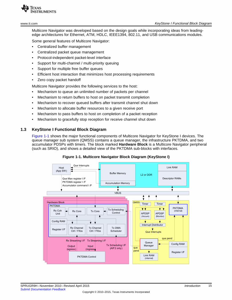
Some general features of Multicore Navigator:• Centralized buffer management• Centralized packet queue management• Protocol-independent packet-level interface• Support for multi-channel / multi-priority queuing• Support for multiple free buffer queues• Efficient host interaction that minimizes host processing requirements• Zero copy packet handoff
Multicore Navigator provides the following services to the host:• Mechanism to queue an unlimited number of packets per channel• Mechanism to return buffers to host on packet transmit completion• Mechanism to recover queued buffers after transmit channel shut down• Mechanism to allocate buffer resources to a given receive port• Mechanism to pass buffers to host on completion of a packet reception• Mechanism to gracefully stop reception for receive channel shut down
1.3 KeyStone I Functional Block DiagramFigure 1-1 shows the major functional components of Multicore Navigator for KeyStone I devices. Thequeue manager sub system (QMSS) contains a queue manager, the infrastructure PKTDMA, and twoaccumulator PDSPs with timers. The block marked Hardware Block is a Multicore Navigator peripheral(such as SRIO), and shows a detailed view of the PKTDMA sub-blocks with interfaces.
Figure 1-1. Multicore Navigator Block Diagram (KeyStone I)
15SPRUGR9H–November 2010–Revised April 2015 IntroductionSubmit Documentation Feedback
Copyright © 2010–2015, Texas Instruments Incorporated

Queue Manager Sub System(Keystone 2)
QM 1
(queues
0..8191)
QM 2
(queues
8192..16383)
Link RAM
(32K
entries)
PDSP
1
PDSP
2
Timer Timer
PDSP
3
PDSP
4
Timer Timer
PDSP
5
PDSP
6
Timer Timer
PDSP
7
PDSP
8
Timer Timer
PktDMA 2
que_pend que_pend
Link ram cfg
Desc mem cfg
Link ram cfg
Desc mem cfg
PktDMA 1
que_pend
INTD 1 INTD 2 INTD 1 INTD 2
Que interrupts
KeyStone II Changes to QMSS www.ti.com
1.4 KeyStone II Changes to QMSSFor KeyStone II devices, the following changes were made to the Queue Manager Sub System:• K2K, K2H only: Two hardware queue managers (QM1, QM2), including:
– 8192 queues per queue manager– 64 descriptor memory regions per queue manager– 3 linking RAMs (one internal to QMSS, supporting 32K descriptors)
• K2K, K2H only: Two infrastructure PKTDMAs (PKTDMA1 driven by QM1, PKTDMA2 driven by QM2)• Eight packed-data structure processors (PDSP1 to PDSP8), each with its own dedicated Timer module• Two interrupt distributors (INTD1, INTD2), which service two pairs of PDSPs.
These changes are shown in Figure 1-2. K2L and K2E devices do not contain QM2, PKTDMA2 and havea 16K entry Linking RAM.
Figure 1-2. Queue Manager Sub System for KeyStone II
1.5 KeyStone II QMSS Modes of UseAs described in the previous section, the KeyStone II QMSS is roughly a doubling of the modules in theKeyStone I QMSS. One component that was doubled in size, but not in number, is the internal linkingRAM. Both QM1 and QM2 share this component. The programming of each QM’s linking RAM anddescriptor memory region registers determines if the linking RAM is used cooperatively (Shared Mode) orindependently (Split Mode).
16 Introduction SPRUGR9H–November 2010–Revised April 2015Submit Documentation Feedback
Copyright © 2010–2015, Texas Instruments Incorporated
0
QMSS Link RAM
(split mode use )
16K-1(indexes) 016K-1
QM 1 program:
Region0 base addr = 0x00100000
Region0 size = 0x00003FFF
QM 2 program:
Region0 base addr = 0x00120000
Region0 size = 0x00003FFF
0
QMSS Link RAM
(shared mode use )
32K-1(indexes)
QM 1 program:
Region0 base addr = 0x00100000
Region0 size = 0x00007FFF
QM 2 program:
Region0 base addr = 0x00100000
Region0 size = 0x00007FFF
www.ti.com KeyStone II QMSS Modes of Use
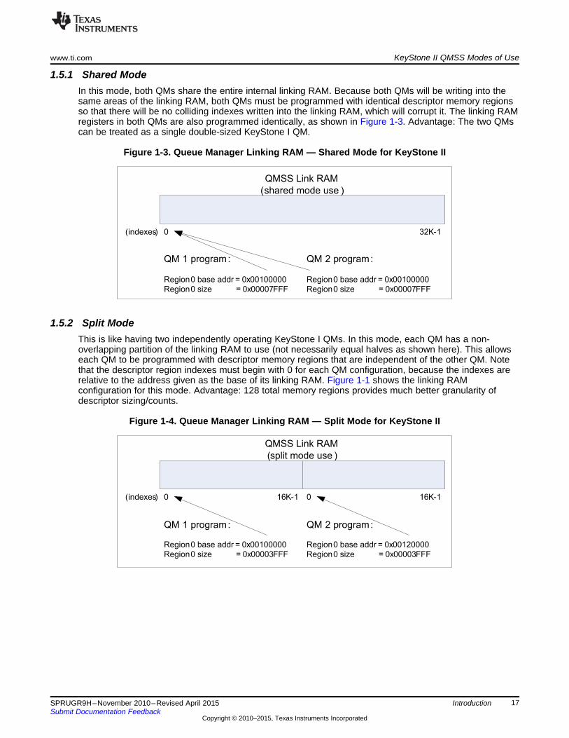
1.5.1 Shared ModeIn this mode, both QMs share the entire internal linking RAM. Because both QMs will be writing into thesame areas of the linking RAM, both QMs must be programmed with identical descriptor memory regionsso that there will be no colliding indexes written into the linking RAM, which will corrupt it. The linking RAMregisters in both QMs are also programmed identically, as shown in Figure 1-3. Advantage: The two QMscan be treated as a single double-sized KeyStone I QM.
Figure 1-3. Queue Manager Linking RAM — Shared Mode for KeyStone II
1.5.2 Split ModeThis is like having two independently operating KeyStone I QMs. In this mode, each QM has a non-overlapping partition of the linking RAM to use (not necessarily equal halves as shown here). This allowseach QM to be programmed with descriptor memory regions that are independent of the other QM. Notethat the descriptor region indexes must begin with 0 for each QM configuration, because the indexes arerelative to the address given as the base of its linking RAM. Figure 1-1 shows the linking RAMconfiguration for this mode. Advantage: 128 total memory regions provides much better granularity ofdescriptor sizing/counts.
Figure 1-4. Queue Manager Linking RAM — Split Mode for KeyStone II
17SPRUGR9H–November 2010–Revised April 2015 IntroductionSubmit Documentation Feedback
Copyright © 2010–2015, Texas Instruments Incorporated

Overview www.ti.com
1.6 OverviewMulticore Navigator specifies the data structures used by Texas Instruments standard communicationsmodules to facilitate direct memory access (DMA) and to provide a consistent application programminginterface (API) to the host software in multi-core devices. The data structures and the API used tomanipulate them will be jointly referred to as Multicore Navigator.
Frequent tasks are commonly offloaded from the host processor (DSP core) to peripheral hardware toincrease system performance. Significant performance gains may result from careful design of the hostsoftware and communication module interface. In networking systems, packet transmission and receptionare critical tasks. Texas Instruments has developed the Multicore Navigator standard, which is aimed atmaximizing the efficiency of interaction between the host software and communications modules.
The design goals for Multicore Navigator are as follows:• Minimize host interaction• Maximize memory use efficiency• Maximize bus burst efficiency• Maximize symmetry between transmit/receive operations• Maximize scalability for number of connections / buffer sizes / queue sizes / protocols supported• Minimize protocol specific features• Minimize complexity
1.7 Queue ManagerThe queue manager is a hardware module that is responsible for accelerating management of the packetqueues. Packets are added to a packet queue by writing the 32-bit descriptor address to a particularmemory mapped location in the queue manager module. Packets are de-queued by reading the samelocation for that particular queue. Multicore Navigator queue manager modules are capable of queuingonly descriptors that have been allocated from the descriptor regions of the associated queue manager.
1.8 Packet DMA (PKTDMA)The Packet DMA is a DMA in which data destination is determined by a destination and free descriptorqueue index, not an absolute memory address. In receive mode, the PKTDMA fetches a free descriptor,traverses the descriptor to find the buffer, PKTDMA transfers the payload into the buffer, and puts thedescriptor into the destination queue. In transmit mode, the PKTDMA pops the descriptor from the TXqueue, traverses the descriptor, reads the payload from the buffer, and DMA transfers the payload to thetransmit port.
1.9 Navigator CloudA Navigator Cloud is a set of PKTDMAs and descriptors. Neither PKTDMAs nor descriptors address thephysical Queue Manager(s) directly, but instead use a queue_manager:queue_number (qmgr:qnum)notation and registers to create a logical mapping into the physical Queue Manager(s). All PKTDMAs withthe same logical mapping are said to be part of the same Navigator Cloud. A descriptor can be sent toany PKTDMA in the same cloud, but may or may not transfer correctly through PKTDMAs in differentclouds. A non-compatible logical qmgr:qnum mapping will cause descriptors to arrive in unexpectedqueues, potentially causing a memory leak.
It is possible to send a descriptor from one cloud to another, but each qmgr:qnum reference must point tothe same physical queue for the PKTDMAs in both clouds. Another way to say this is by example: LetPKTDMA 1 and 2 have the same base addresses programmed for logical QM0 and QM1 in theirrespective QMn Base Address registers, but their QM2 and QM3 base addresses are different (so bydefinition they represent different clouds). Any descriptor traveling between them must reference onlyQM0 and/or QM1 in every descriptor and RX Flow qmgr:qnum fields. This is especially true if the RX(output) queue for the first PKTDMA is the same physical queue as the TX (input) queue for the secondPKTDMA.
18 Introduction SPRUGR9H–November 2010–Revised April 2015Submit Documentation Feedback
Copyright © 2010–2015, Texas Instruments Incorporated

www.ti.com Virtualization
1.10 VirtualizationPhysical memory addresses can be virtualized by using the MPAX units inside the MSMC controller andC66x CorePacs. It is important to understand how Navigator uses virtualized addresses in a system whereboth physical and virtual addresses may be used by various components, or when different mappings mayaddress the same physical memory. Here is the summary:• The Queue Manager does not understand memory translations. It simply converts QM pushed
addresses to linking RAM indexes based on the programming of QMSS Memory Regions (seeSection 4.1.3). Virtual addresses can be used, but they must be programmed into the QMSS MemoryRegions and used for every push and descriptor reference. Using a physical address when virtualaddresses have been programmed into QMSS will result in erroneous behavior.
• The PKTDMA also does not understand memory translations. It simply makes VBUS transactionsusing popped descriptor addresses and the memory references inside descriptors. A virtual addressused by the PKTDMA will be translated by MPAX to a physical address. Because the PKTDMA usespopped addresses, addresses embedded in descriptors, and Rx Flow configurations (containingqmgr:qnum mappings), these must all present a unified view of memory or the result of transfers willbe unexpected.
1.11 ARM-DSP Shared UseMost of the time, an ARM’s memory virtualization will be different than that of the DSPs. Both ARMs andDSPs should define their own Navigator Cloud(s). This is an easy and efficient way to keep resourcesseparated. However, most ARM-DSP applications require transferring data between them. There are atleast two ways to do this: 1) either use a PKTDMA to transfer data from one cloud to another, or 2) createa common shared area to be used by both. The common shared area is the preferred approach, becausePKTDMA loading may be reduced, and because configuring two clouds to communicate can sometimesbe difficult.
In the common shared area approach, one or more Navigator Clouds are defined specifically for ARM-DSP data transfers. This means that memory virtualization is the same (ARM, DSP and QMSS use thesame address regions whether virtual or physical), they use common descriptor memory regions, and alldescriptor references point to memory and queues containing descriptors from one of the commondescriptor memory regions.
In this approach, either the ARM or DSP writes data to the common shared area and the recipient isnotified. This is done without the PKTDMA because no data transfer is necessary, and notification isaccomplished using the QM by itself. Notification occurs with either a queue pend queue and an interrupton the recipient core, or the recipient core polling on the receive queue.
1.12 PDSP FirmwareWithin the QMSS are two or eight PDSPs, each capable of running firmware that performs QMSS-relatedfunctions, such as accumulation, QoS, or event management (job load balancing). The accumulatorfirmware’s job is to poll a select number of queues looking for descriptors that have been pushed intothem. Descriptors are popped from the queue and placed in a buffer provided by the host. When the listbecomes full or a programmed time period expires, the accumulator triggers an interrupt to the host toread the buffer for descriptor information.
The accumulation firmware also provides a reclamation feature that automatically recycles descriptors toqueues exactly as if the descriptor had been processed by the TX PKTDMA.
The QoS firmware’s responsibility is to ensure that peripherals and the host CPU are not overwhelmedwith packets. This is also known as traffic shaping, and is managed through the configuration of ingressand egress queues.
The timer periods for polling queues and for host interrupt triggering are programmable. Specific interruptand queue assignments are listed later in this document.
Event management is handled by the Open Event Manager (OEM) software, which is a combination ofPDSP firmware (scheduler) and CorePac software (dispatcher). Complete details are available in the OEMuser’s guide (available in the release zips).
19SPRUGR9H–November 2010–Revised April 2015 IntroductionSubmit Documentation Feedback
Copyright © 2010–2015, Texas Instruments Incorporated

PDSP Firmware www.ti.com
20 Introduction SPRUGR9H–November 2010–Revised April 2015Submit Documentation Feedback
Copyright © 2010–2015, Texas Instruments Incorporated

Chapter 2SPRUGR9H–November 2010–Revised April 2015
Operational Concepts
This chapter introduces the data movement concepts and data structures used by Multicore Navigator.Thorough understanding of these concepts is necessary for effective programming of the device. Low-level (bit field) descriptions are provided in later chapters.
Topic ........................................................................................................................... Page
2.1 Packets ............................................................................................................. 222.2 Queues ............................................................................................................. 222.3 Queue Types ..................................................................................................... 222.4 Descriptors........................................................................................................ 232.5 Packet DMA ....................................................................................................... 252.6 Packet Transmission Overview ............................................................................ 252.7 Packet Reception Overview ................................................................................. 262.8 ARM Endianess.................................................................................................. 28
21SPRUGR9H–November 2010–Revised April 2015 Operational ConceptsSubmit Documentation Feedback
Copyright © 2010–2015, Texas Instruments Incorporated

Packets www.ti.com
2.1 PacketsA packet is the logical grouping of a descriptor and the payload data attached to it. The payload data maybe referred to as packet data or a data buffer, and depending on the descriptor type, may be contiguouswith the descriptor fields, or may somewhere else in memory with a pointer stored in the descriptor.
2.2 QueuesQueues are used to hold pointers to packets while they are being passed between the host and / or any ofthe ports in the system. Queues are maintained within the queue manager module.
2.2.1 Packet QueuingQueuing of packets onto a packet queue is accomplished by writing a pointer to the descriptor (and insome cases the length of the packet) into a specific set of addresses within the queue manager module.Packets may be queued either onto the head or the tail of the queue and this is selected based on a bit inthe Queue Register C for the queue. By default, packets will be added to the tail of a queue if the QueueRegister C has not been written. The queue manager provides a unique set of addresses for addingpackets for each queue that it manages. The host accesses the queue management registers via a queueproxy, which ensures that all pushes are atomic, eliminating the need for locking mechanisms in thedevice.
2.2.2 Packet De-queuingDe-queuing of packets from a packet queue is accomplished by reading the head packet pointer from thecorresponding address in the queue manager. After the head pointer has been read, the queue managerwill invalidate the head pointer and will replace it with the next packet pointer in the queue. Thisfunctionality, which is implemented in the queue manager, prevents the ports from needing to traverselinked lists and allows for certain optimizations to be performed within the queue manager.
2.2.3 Queue ProxyThe Queue Proxy is a module that provides atomic queue pushes across the cores in KeyStonearchitecture devices. The purpose of the proxy is to accept a Que N Reg C write followed by a Que N RegD write without allowing another core to inject its own push. The method of pushing to the Queue Proxy isidentical to writing to the Que N Reg C and D registers contained in the Queue Management Region,except at a different address (the same offset within the Queue Proxy Region). Each core is connected tothe proxy and the proxy identifies it using its VBUS master ID. Simultaneous writes by two or more coresare arbitrated by round-robin. Queue pushes using only Reg D do not need to use the proxy and maywrite to the Queue Management Region. All registers in the Queue Proxy Region are write only, and readswill return 0 (so there is no queue popping from this region). Because Que N Reg A and B are read only,they are not supported in the Queue Proxy.
Another important consideration is use of the Queue Proxy in a multitasking environment. The proxycannot differentiate writes having different sources within the same core (such as multiple threads). If anapplication pushes to queues using Reg C and D, and multiple threads may push to the same queue, theapplication must protect these pushes using a resource management method such as critical sections,semaphore, etc.
2.3 Queue TypesThis section describes the various types of queues that are used for transmitting and receiving packetsthrough Multicore Navigator.
2.3.1 Transmit QueuesEach PKTDMA transmit (Tx) channel is attached to a single queue via a dedicated que_pend signal (seeFigure 1-1, and Figure 1-2). These special queues are called transmit queues (the mappings aredescribed in Section 5.2). This queue stores all the packets waiting to be transmitted on this Tx channel,allowing transmit queues to provide input (incoming) data to the PKTDMA. When the Tx channel isenabled, the que_pend signal automatically notifies the PKTDMA that packets are waiting.
22 Operational Concepts SPRUGR9H–November 2010–Revised April 2015Submit Documentation Feedback
Copyright © 2010–2015, Texas Instruments Incorporated
www.ti.com Queue Types
2.3.2 Transmit Completion QueuesFollowing packet transmission, the PKTDMA automatically recycles descriptors to a specified queue sothat the application can use the descriptor again for another packet. This queue is known as a transmitcompletion queue, or Tx FDQ (free descriptor queue). These queues are chosen by the application, andare specified in the descriptor header itself. Normally, the application pre-loads this queue withdescriptors, then pops one at a time and pushes to a transmit queue.
2.3.3 Receive QueuesFor packets flowing out of the PKTDMA to a memory endpoint, the PKTDMA uses a receive queue as adestination queue for the packet. This is an application-selected queue that doesn’t necessarily havespecial hardware such as a que_pend signal, though for certain use-cases, the selected receive queuemay also be a transmit queue for another PKTDMA, or a queue pend queue that triggers otherfunctionality such as EDMA. The application selects the receive queue using specific fields in the Rx Flow(see Section 4.2.4).
2.3.4 Free Descriptor Queues (FDQ)A free descriptor queue (FDQ) is a queue pre-loaded with descriptors to be used during runtime. ForPKTDMA receive processing, the PKTDMA uses up to four Rx FDQs to provide memory addresses for thepacket destination. In this case, the PKTDMA pops from these Rx FDQs and pushes the completedpacket to the indicated receive queue. It is also common practice to push all descriptors defined bydescriptor memory regions (see Section 4.1.3) to “global” FDQs to be distributed out to other FDQs asneeded.
2.3.4.1 Host Packet Free DescriptorsHost packets queued to a FDQ must have a buffer linked to them, and the buffer size set appropriately.The RX DMA will pop the host packets as required, filling them up to their indicated buffer size, and, ifneeded, will pop additional host packet descriptors and link them as host buffers to the initial host packet.The RX DMA will not look for host buffers pre-linked to host packets as is done by the TX DMA.
2.3.4.2 Monolithic Free DescriptorsThe RX DMA does not read any values from a monolithic FD. It is assumed by the PKTDMA that the sizeof the descriptor is large enough to hold all the packet data. Data exceeding the descriptor’s size willcause an overwrite of the next descriptor, which may cause undefined results. This calls for careful systeminitialization.
2.3.5 Queue Pend QueuesA queue pend queue is a queue with a dedicated que_pend signal (see Figure 1-1, and Figure 1-2) thatconnects the queue to one or more interrupt controllers. These mappings are described in Section 5.2.When the number of descriptors pushed to the queue match the threshold set in Queue N Status andConfiguration Register D (see Section 4.1.5.4), the signal becomes active, triggering the input event in thecontrollers.
2.4 DescriptorsDescriptors are small memory areas that describe the packet of data to be transferred through the system.
Descriptor types are discussed and shown in bit-level detail in the Chapter 3 chapter, but briefly, thedescriptor types are:
2.4.1 Host PacketHost packet descriptors have a fixed size information (or description) area that contains a pointer to a databuffer, and optionally, a pointer to link one or more host buffer descriptors. Host packets are linked in TXby the host application, and by the RX DMA in RX (host packets should not be prelinked when creating anRX FDQ during initialization).
23SPRUGR9H–November 2010–Revised April 2015 Operational ConceptsSubmit Documentation Feedback
Copyright © 2010–2015, Texas Instruments Incorporated
Queue Manager(N = 0 to 8191)
Queue Packet
De-queue Packet
HostPacket
Descriptor(SOP)
Queue NHead
Pointer
Link
Link
Link
HostPacket
Descriptor(SOP)
NULL
Pointer
Queue
Link
NULL
Packet 1MOP Data
Buffer
Packet 1MOP Data
Buffer
Packet 2DataBuffer
Packet 1SOP Data
Buffer
Packet 3SOP Data
Buffer
Packet 1EOP Data
Buffer
NULL
HostBuffer
Descriptor(MOP)
HostBuffer
Descriptor(MOP)
HostBuffer
Descriptor(EOP)
MonolithicPacket
Descriptor
Descriptors www.ti.com
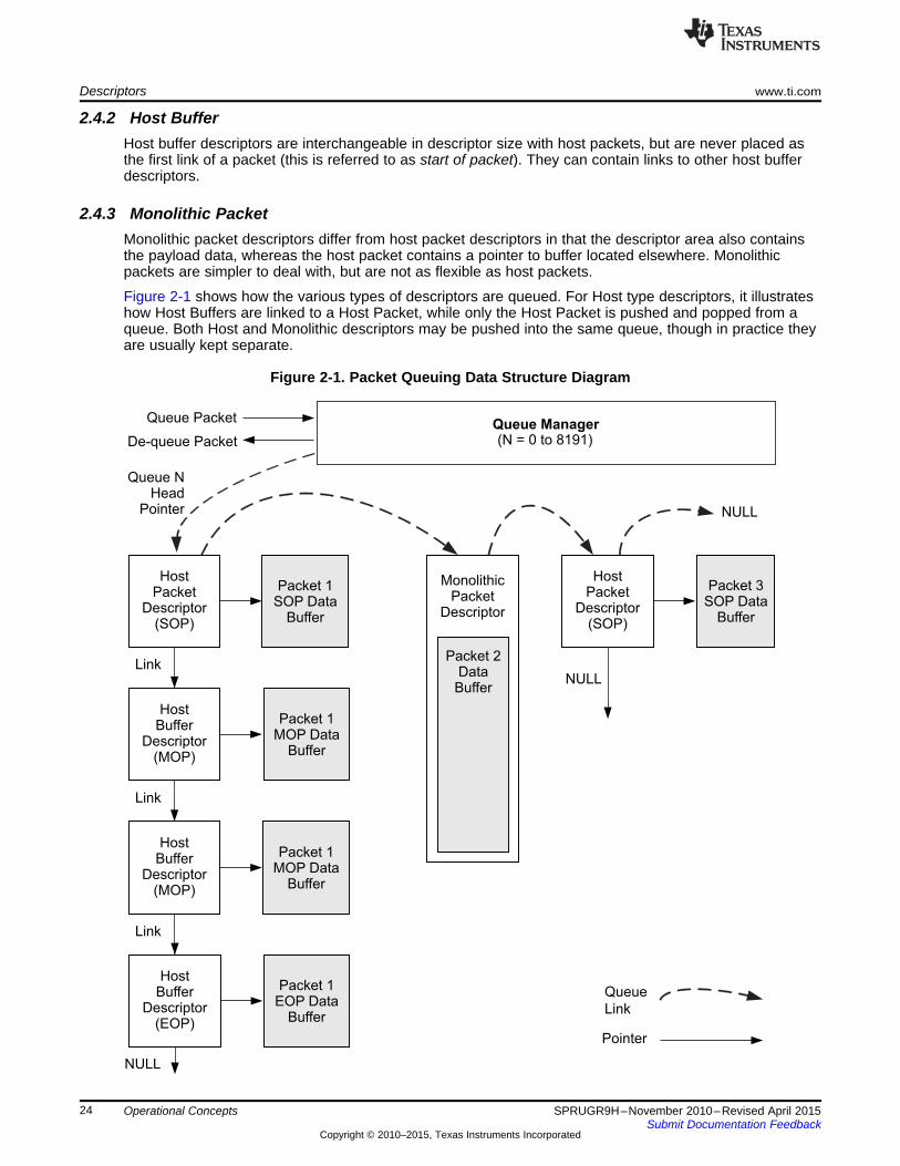
2.4.2 Host BufferHost buffer descriptors are interchangeable in descriptor size with host packets, but are never placed asthe first link of a packet (this is referred to as start of packet). They can contain links to other host bufferdescriptors.
2.4.3 Monolithic PacketMonolithic packet descriptors differ from host packet descriptors in that the descriptor area also containsthe payload data, whereas the host packet contains a pointer to buffer located elsewhere. Monolithicpackets are simpler to deal with, but are not as flexible as host packets.
Figure 2-1 shows how the various types of descriptors are queued. For Host type descriptors, it illustrateshow Host Buffers are linked to a Host Packet, while only the Host Packet is pushed and popped from aqueue. Both Host and Monolithic descriptors may be pushed into the same queue, though in practice theyare usually kept separate.
Figure 2-1. Packet Queuing Data Structure Diagram
24 Operational Concepts SPRUGR9H–November 2010–Revised April 2015Submit Documentation Feedback
Copyright © 2010–2015, Texas Instruments Incorporated

www.ti.com Packet DMA
2.5 Packet DMAThe Packet DMA (or PKTDMA) used within Multicore Navigator is like most DMAs in that it is primarilyconcerned with moving data from point to point. It is unlike some DMAs in that it is unaware of the payloaddata’s structure. To the PKTDMA, all payloads are simple one-dimensional byte streams. Programmingthe PKTDMA is accomplished through correct initialization of descriptors, PKTDMA RX/TX channels, andRX flows.
2.5.1 ChannelsEach PKTDMA in the system is configured with a number of receive (RX) and transmit (TX) channels (seeSection 5.4 for details). A channel may be thought of a pathway through the PKTDMA. Once the PKTDMAhas started a packet on a channel, that channel cannot be used by any other packet until the currentpacket is completed. Because there are multiple channels for RX and TX, multiple packets may be in-flightsimultaneously, and in both directions, because each PKTDMA contains separate DMA engines for RXand TX.
2.5.2 RX FlowsFor transmit, the TX DMA engine uses the information found in the descriptor fields to determine how toprocess the TX packet. For receive, the RX DMA uses a flow. A flow is a set of instructions that tells theRX DMA how to process the RX packet. It is important to note that there is not a correspondence betweenRX channel and RX flow, but rather between RX packet and RX flow. For example, one peripheral maycreate a single RX flow for all packets across all channels, and another may create several flows for thepackets on each channel.
For loopback PKTDMA modes (i.e. infrastructure cases), the RX flow is specified in the TX descriptor, inthe SOURCE_TAG_LO field. The PKTDMA will pass this value to the streaming I/F as flow index. In non-loopback cases, the RX flow is specified in the packet info structure of the Streaming I/F. In the event noRX flow is specified, the RX DMA will use RX flow N for RX channel N.
2.6 Packet Transmission OverviewAfter a TX DMA channel has been initialized, it can begin to be used to transmit packets. Packettransmission involves the following steps:1. The host is made aware of one or more chunks of data in memory that need to be transmitted as a
packet. This may involve directly sourcing data from the host or it may involve data that has beenforwarded from another data source in the system.
2. The host allocates a descriptor, usually from a TX completion queue, and fills in the descriptor fieldsand payload data.
3. For host packet descriptors, the host allocates and populates host buffer descriptors as necessary topoint to any remaining chunks of data that belong to this packet.
4. The host writes the pointer to the packet descriptor into a specific memory mapped location inside thequeue manager that corresponds to one of the transmit queues for the desired DMA channel.Channels may provide more than one TX queue and may provide a particular prioritization policybetween the queues. This behavior is application-specific and is controlled by the DMA controller /scheduler implementation.
5. The queue manager provides a level sensitive status signal for the queue that indicates if any packetsare currently pending. This level-sensitive status line is sent to the hardware block that is responsiblefor scheduling DMA operations.
6. The DMA controller is eventually brought into context for the corresponding channel and begins toprocess the packet.
7. The DMA controller reads the packet descriptor pointer and descriptor size hint information from thequeue manager. This is the push value written to the Queue N Reg D registers.
8. The DMA controller reads the packet descriptor from memory.9. The DMA controller empties the buffer (or for linked host packets, each buffer in sequence specified by
the next descriptor pointer) by transmitting the contents in one or more block data moves. The size ofthese blocks is application-specific.
25SPRUGR9H–November 2010–Revised April 2015 Operational ConceptsSubmit Documentation Feedback
Copyright © 2010–2015, Texas Instruments Incorporated
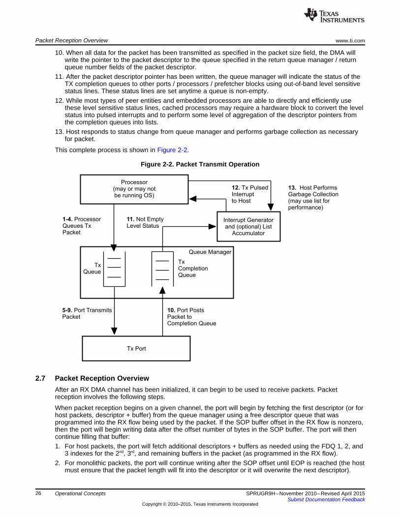
Processor(may or may notbe running OS)
Queue Manager
TxQueue
TxCompletionQueue
Tx Port
1-4. ProcessorQueues TxPacket
5-9. Port TransmitsPacket
10. Port PostsPacket toCompletion Queue
13. Host PerformsGarbage Collection(may use list forperformance)
12. Tx PulsedInterruptto Host
Interrupt Generatorand (optional) List
Accumulator
11. Not EmptyLevel Status
Packet Reception Overview www.ti.com
10. When all data for the packet has been transmitted as specified in the packet size field, the DMA willwrite the pointer to the packet descriptor to the queue specified in the return queue manager / returnqueue number fields of the packet descriptor.
11. After the packet descriptor pointer has been written, the queue manager will indicate the status of theTX completion queues to other ports / processors / prefetcher blocks using out-of-band level sensitivestatus lines. These status lines are set anytime a queue is non-empty.
12. While most types of peer entities and embedded processors are able to directly and efficiently usethese level sensitive status lines, cached processors may require a hardware block to convert the levelstatus into pulsed interrupts and to perform some level of aggregation of the descriptor pointers fromthe completion queues into lists.
13. Host responds to status change from queue manager and performs garbage collection as necessaryfor packet.
This complete process is shown in Figure 2-2.
Figure 2-2. Packet Transmit Operation
2.7 Packet Reception OverviewAfter an RX DMA channel has been initialized, it can begin to be used to receive packets. Packetreception involves the following steps.
When packet reception begins on a given channel, the port will begin by fetching the first descriptor (or forhost packets, descriptor + buffer) from the queue manager using a free descriptor queue that wasprogrammed into the RX flow being used by the packet. If the SOP buffer offset in the RX flow is nonzero,then the port will begin writing data after the offset number of bytes in the SOP buffer. The port will thencontinue filling that buffer:1. For host packets, the port will fetch additional descriptors + buffers as needed using the FDQ 1, 2, and
3 indexes for the 2nd, 3rd, and remaining buffers in the packet (as programmed in the RX flow).2. For monolithic packets, the port will continue writing after the SOP offset until EOP is reached (the host
must ensure that the packet length will fit into the descriptor or it will overwrite the next descriptor).
26 Operational Concepts SPRUGR9H–November 2010–Revised April 2015Submit Documentation Feedback
Copyright © 2010–2015, Texas Instruments Incorporated

Host Processor(running OS)
Queue Manager
Rx FreeDescriptor /
Buffer Queue
RxQueue
Rx Port
2. Port FetchesFree Descriptors +Buffers During Rx
3. Port PostsPacket toRx Queue
6. Host PerformsGarbage Collection(may use list forperformance)
5. Tx PulsedInterruptto Host
Interrupt Generatorand (optional)
List Accumulator
4. Not EmptyLevel Status
INIT: Host Allocates RxFree Descriptors andInits FDB Queue HostLinks OS Buffers toLocal CPPI Descriptors
www.ti.com Packet Reception Overview
The PKTDMA performs the following operations when the entire packet has been received:1. Writes the packet descriptor to memory. Most of the fields of the descriptor will be overwritten by the
RX DMA. See the RX Overwrite column of the descriptor layouts in Chapter 3 for field-specific detail.For monolithic packets, the DMA does not even read the descriptor until it is time to write to thedescriptor fields at EOP.
2. Writes the packet descriptor pointer to the appropriate RX queue. The absolute queue that eachpacket to be forwarded to on completion of reception will either be the queue that was specified in theRX_DEST_QMGR and RX_DEST_QNUM fields in the RX flow. The port is explicitly allowed tooverride this destination queue using application specific methods.
The queue manager is responsible for indicating the status of the receive queues to other ports /embedded processors using out-of-band level sensitive status lines. These status lines are set anytime aqueue is non-empty.
Figure 2-3 shows a diagram of the overall receive operation.
Figure 2-3. Packet Receive Operation
27SPRUGR9H–November 2010–Revised April 2015 Operational ConceptsSubmit Documentation Feedback
Copyright © 2010–2015, Texas Instruments Incorporated

ARM Endianess www.ti.com
2.8 ARM EndianessThis section pertains only to KeyStone devices containing an ARM processor.
Memory access between the ARM subsystem and the rest of the device is accomplished with theOCP2VBUSM bridge. This bridge performs endianess translations when the device is in big endian mode.The ARM always operates in little endian mode. For Navigator purposes, some data and data structuresrequire manipulation when accessed by a program running on the ARM:• Descriptors. The header portion needs to be byte-swapped prior to pushing and following popping.
Navigator uses a notion of descriptor ownership in that when the descriptor is pushed to a queue it isowned by the hardware, and owned by software when not pushed to a queue. Byte swapping followsthis nicely in that when a descriptor is popped from a queue it should be byte swapped prior to readingheader fields, then byte swapped again just before pushing it back to a queue. For linked Hostdescriptors, care must be taken to make sure that the next pointer has been byte swapped correctly forthe ARM.
• Payload data for IP. For TX data going into an IP (such as an FFTC), the data needs to be byteswapped prior to pushing the corresponding descriptors. Similarly, when consuming an RX descriptorfrom an IP, the payload also needs to be swapped.
• Accumulator lists. The list of descriptor addresses provided by the Accumulator firmware needs to bebyte swapped prior to consumption. Care must be taken due to the ping-pong nature of the lists; byte-swap only one side at a time - the side that is being consumed.
28 Operational Concepts SPRUGR9H–November 2010–Revised April 2015Submit Documentation Feedback
Copyright © 2010–2015, Texas Instruments Incorporated

www.ti.com ARM Endianess
29SPRUGR9H–November 2010–Revised April 2015 Operational ConceptsSubmit Documentation Feedback
Copyright © 2010–2015, Texas Instruments Incorporated

Chapter 3SPRUGR9H–November 2010–Revised April 2015
Descriptor Layouts
Descriptors are memory areas that describe the contents of a packet. This memory may be co-locatedwith the packet data, or may contain pointers to the data.
Topic ........................................................................................................................... Page
3.1 Host Packet Descriptor ....................................................................................... 313.2 Host Buffer Descriptor ........................................................................................ 353.3 Monolithic Descriptor ......................................................................................... 37
30 Descriptor Layouts SPRUGR9H–November 2010–Revised April 2015Submit Documentation Feedback
Copyright © 2010–2015, Texas Instruments Incorporated

www.ti.com Host Packet Descriptor
3.1 Host Packet DescriptorHost packet descriptors are designed to be used when the application requires support for true, unlimitedfragment count scatter / gather-type operations. The host packet descriptor contains the followinginformation:• Indicator that identifies the descriptor as a host packet descriptor• Source and destination tags• Packet type• Packet length• Protocol-specific region size• Protocol-specific control / status bits• Pointer to the first valid byte in the SOP data buffer• Length of the SOP data buffer• Pointer to the next buffer descriptor in the packet• Software-specific information
Host packet descriptors always contain 32 bytes of required information and may also contain optionalsoftware-specific information and protocol-specific information. How much optional information (andtherefore the allocated size of the descriptors) is required is application-dependent. The descriptor layoutis shown in Table 3-1.
Table 3-1. Host Packet Descriptor Layout
Packet info (12 bytes)Buffer info (8 bytes)Linking info (4 bytes)Original buffer info
(8 bytes)Extended packet info block (optional)
Includes timestamp and software data (16 bytes)Protocol-specific data (optional)
(0 to M bytes where M is a multiple of 4)Other SW data (optional and user defined)
Packet info(12 bytes)
Buffer info (8 bytes)Linking info
(4 bytes)Original buffer info
(8 bytes)Extended packet info block (optional)
Includes timestamp and software data (16 bytes)Protocol-specific data (optional)
(0 to M bytes where M is a multiple of 4)Other SW data (optional and user defined)
Host packet descriptors may be linked with zero or more additional host buffer descriptors in a singly-linked-list fashion to form packets. Each host packet consists of a single host packet descriptor followedby a chain of zero or more host buffer descriptors linked together using the next descriptor pointer fields inthe descriptors. The last descriptor in a host packet has a 0 next descriptor pointer.
The other SW data portion of the descriptor exists after all of the defined words and is reserved for use bythe host software to store completely private data. This region is not used in any way by the DMA orqueue manager modules in a Multicore Navigator system and these modules will not modify any byteswithin this region.
The contents of the host packet descriptor words are detailed in the following tables:
31SPRUGR9H–November 2010–Revised April 2015 Descriptor LayoutsSubmit Documentation Feedback
Copyright © 2010–2015, Texas Instruments Incorporated

Host Packet Descriptor www.ti.com
Table 3-2. Host Packet Descriptor Packet Information Word 0 (PD Word 0)
RXBits Name Description Overwrite31-30 Packet Id Host packet descriptor type identifier. Value is always 0 (0x0) for Host Packet descriptors. Yes29-25 Packet Type This field indicates the type of this packet and is encoded as follows: Yes
0-31 = To Be Assigned24-23 Reserved Unused Yes22 Protocol Specific This field indicates the location of the protocol-specific words: Yes
Region Location • 0 = PS words are located in the descriptor• 1 = PS words are located in the SOP Buffer immediately prior to the data.
21-0 Packet Length The length of the packet data in bytes. If the packet length is less than the sum of the Yesbuffer lengths, then the packet data will be truncated. A packet length greater than the sumof the buffers is an error. The valid range for the packet length is 0 to 4M-1 bytes. If thepacket length is set to 0, the port will not actually transmit any information. Instead, the portwill perform buffer / descriptor reclamation as instructed in the return information in word 2.
Table 3-3. Host Packet Descriptor Packet Information Word 1 (PD Word 1)
RXBits Name Description Overwrite31-24 Source Tag - Hi This field is application-specific. During packet reception, the DMA controller in the port will Configurable
overwrite this field as specified in the RX_SRC_TAG_HI_SEL field in the flow configurationtable entry.
23-16 Source Tag - Lo This field is application-specific. During packet reception, the DMA controller in the port will Configurableoverwrite this field as specified in the RX_SRC_TAG_LO_SEL field in the flow configurationtable entry. For TX, this value supplies the RX flow index to the Streaming I/F for infrastructureuse.
15-8 Dest Tag – Hi This field is application specific. During packet reception, the DMA controller in the port will Configurableoverwrite this field as specified in the RX_DEST_TAG_HI_SEL field in the flow configurationtable entry.
7-0 Dest Tag - Lo This field is application specific. During packet reception, the DMA controller in the port will Configurableoverwrite this field as specified in the RX_DEST_TAG_LO_SEL field in the flow configurationtable entry.
Table 3-4. Host Packet Descriptor Packet Information Word 2 (PD Word 2)
RXBits Name Description Overwrite31 Extended Packet Info Block This field indicates the presence of the extended packet info block in the descriptor. Yes
Present • 0 = EPIB is not present• 1 = 16 byte EPIB is present
30 Reserved Unused Yes29-24 Protocol Specific Valid This field indicates the valid # of 32-bit words in the protocol-specific region. This is Yes
Word Count encoded in increments of 4 bytes as follows:• 0 = 0 bytes• 1 = 4 bytes…• 16 = 64 bytes…32 = 128 bytes33-63 = Reserved
23-20 Error Flags This field contains error flags that can be assigned based on the packet type Yes19-16 Protocol Specific Flags This field contains protocol-specific flags / information that can be assigned based Yes
on the packet type.15 Return Policy No• This field indicates the return policy for this packet.
• 0 = Entire packet (still linked together) should be returned to queue specified inbits 13-0 below.
• 1 = Each buffer should be returned to queue specified in bits 13-0 of Word 2 intheir respective descriptors. The TX DMA will return each buffer in sequence.
32 Descriptor Layouts SPRUGR9H–November 2010–Revised April 2015Submit Documentation Feedback
Copyright © 2010–2015, Texas Instruments Incorporated

www.ti.com Host Packet Descriptor
Table 3-4. Host Packet Descriptor Packet Information Word 2 (PD Word 2) (continued)RX
Bits Name Description Overwrite14 Return Push Policy This field indicates how a transmit DMA should return the descriptor pointers to the No
free queues. This field is encoded as follows:• 0 = Descriptor must be returned to tail of queue• 1 = Descriptor must be returned to head of queueThis bit is used only when the Return Policy bit is set to 1.
13-12 Packet Return Queue Mgr This field indicates which of the four potential queue managers in the system the No# descriptor is to be returned to after transmission is complete. This field is not altered
by the DMA during transmission or reception and should be initialized by the host.11-0 Packet Return Queue # This field indicates the queue number within the selected queue manager that the No
descriptor is to be returned to after transmission is complete. The value 0xFFF isreserved.
Table 3-5. Host Packet Descriptor Buffer 0 Info Word 0 (PD Word 3)
RXBits Name Description Overwrite31-22 Reserved Unused Yes21-0 Buffer 0 Length The buffer length field indicates how many valid data bytes are in the buffer. Unused or Yes
protocol-specific bytes at the beginning of the buffer are not counted in the buffer lengthfield. This value will be overwritten during reception.
Table 3-6. Host Packet Descriptor Buffer 0 Info Word 1 (PD Word 4)
RXBits Name Description Overwrite31-0 Buffer 0 Pointer The buffer pointer is the byte-aligned memory address of the buffer associated with the Yes
buffer descriptor. This value will be written during reception. If the protocol-specific wordsare placed at the beginning of the SOP buffer, this pointer will point to the PS words. Theoffset to the data in that case must be calculated by the consumer using the protocol-specific valid word count from word 2. Usage note: For TX, it is a good practice toinitialize this field and the Original Ptr field in word 7 with the actual buffer address, butthis is the field that is used. For RX, this field may be left uninitialized, or set to 0.
Table 3-7. Host Packet Descriptor Linking Word (PD Word 5)
RXBits Name Description Overwrite31-0 Next Descriptor The 32-bit word-aligned memory address of the next buffer descriptor in the packet. If the Yes
Pointer value of this pointer is 0, then the current buffer is the last buffer in the packet. The hostsets the next descriptor pointer.
33SPRUGR9H–November 2010–Revised April 2015 Descriptor LayoutsSubmit Documentation Feedback
Copyright © 2010–2015, Texas Instruments Incorporated

Host Packet Descriptor www.ti.com
Table 3-8. Host Packet Descriptor Original Buffer Info Word 0 (PD Word 6)
RXBits Name Description Overwrite31-28 Original Buffer 0 Pool This field is used to identify which pool the attached buffer was originally allocated from. No
Index This is distinct from the descriptor pool/queue index because a single buffer may bereferenced by more that one descriptor. This is a software-only field that is not touched bythe hardware.
27-22 Original Buffer 0 This field is used to indicate how many references have been made to the attached buffer NoReference Count by different descriptors. Multiple buffer references are commonly used to implement
broadcast and multicast packet forwarding when zero packet data copies are desired.This is a software-only field that is not touched by the hardware.
21-0 Original Buffer 0 The buffer length field indicates the original size of the buffer in bytes. Data bytes are in NoLength the buffer. This value will not be overwritten during reception. This value is read by the RX
DMA to determine the actual buffer size as allocated by the host at initialization. Becausethe buffer length in Word 3 is overwritten by the RX port during reception, this field isnecessary to permanently store the buffer size information.Usage Note: It is good practice to always set this field during initialization.
Table 3-9. Host Packet Descriptor Original Buffer Info Word 1 (PD Word 7)
RXBits Name Description Overwrite31-0 Original Buffer 0 The buffer pointer is the byte-aligned memory address of the buffer associated with the No
Pointer buffer descriptor. This value will not be overwritten during reception. This value is read bythe RX DMA to determine the actual buffer location as allocated by the host atinitialization. Because the buffer pointer in word 4 is overwritten by the RX port duringreception, this field is necessary to permanently store the buffer pointer information.Usage Note: It is good practice to always set this field during initialization, but is usedonly in RX.
Table 3-10. Host Packet Descriptor Extended Packet Info Block Word 0 (Optional) (1)
RXBits Name Description Overwrite31-0 Timestamp Info This field contains an application-specific timestamp that can be used for traffic shaping in Configurable
a QoS enabled system.(1) This word is present only if the extended packet info block present bit is set in word 2.
Table 3-11. Host Packet Descriptor Extended Packet Info Block Word 1 (Optional) (1)
RXBits Name Description Overwrite31-0 Software Info 0 This field stores software-centric information that needs to travel with the packet through Configurable
the stack. This information will be copied from the source descriptor to the destinationdescriptor whenever a prefetch operation is performed or when transferring through aninfrastructure DMA node.
(1) This word is present only if the Extended Packet Info Block present bit is set in Word 2.
Table 3-12. Host Packet Descriptor Extended Packet Info Block Word 2 (Optional) (1)
RXBits Name Description Overwrite31-0 Software Info 1 This field stores software centric information that needs to travel with the packet through Configurable
the stack. This information will be copied from the source descriptor to the destinationdescriptor whenever a prefetch operation is performed or when transferring through aninfrastructure DMA node.
(1) This word is present only if the Extended Packet Info Block present bit is set in Word 2.
34 Descriptor Layouts SPRUGR9H–November 2010–Revised April 2015Submit Documentation Feedback
Copyright © 2010–2015, Texas Instruments Incorporated
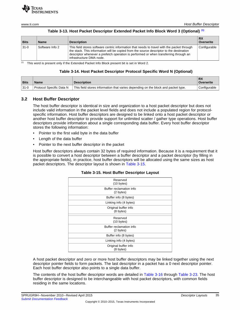
www.ti.com Host Buffer Descriptor
Table 3-13. Host Packet Descriptor Extended Packet Info Block Word 3 (Optional) (1)
RXBits Name Description Overwrite31-0 Software Info 2 This field stores software centric information that needs to travel with the packet through Configurable
the stack. This information will be copied from the source descriptor to the destinationdescriptor whenever a prefetch operation is performed or when transferring through aninfrastructure DMA node.
(1) This word is present only if the Extended Packet Info Block present bit is set in Word 2.
Table 3-14. Host Packet Descriptor Protocol Specific Word N (Optional)
RXBits Name Description Overwrite31-0 Protocol Specific Data N This field stores information that varies depending on the block and packet type. Configurable
3.2 Host Buffer DescriptorThe host buffer descriptor is identical in size and organization to a host packet descriptor but does notinclude valid information in the packet level fields and does not include a populated region for protocol-specific information. Host buffer descriptors are designed to be linked onto a host packet descriptor oranother host buffer descriptor to provide support for unlimited scatter / gather type operations. Host bufferdescriptors provide information about a single corresponding data buffer. Every host buffer descriptorstores the following information:• Pointer to the first valid byte in the data buffer• Length of the data buffer• Pointer to the next buffer descriptor in the packet
Host buffer descriptors always contain 32 bytes of required information. Because it is a requirement that itis possible to convert a host descriptor between a buffer descriptor and a packet descriptor (by filling inthe appropriate fields), in practice, host buffer descriptors will be allocated using the same sizes as hostpacket descriptors. The descriptor layout is shown in Table 3-15.
Table 3-15. Host Buffer Descriptor Layout
Reserved(10 bytes)
Buffer reclamation info(2 bytes)
Buffer info (8 bytes)Linking info (4 bytes)Original buffer info
(8 bytes)
Reserved(10 bytes)
Buffer reclamation info(2 bytes)
Buffer info (8 bytes)Linking info (4 bytes)Original buffer info
(8 bytes)
A host packet descriptor and zero or more host buffer descriptors may be linked together using the nextdescriptor pointer fields to form packets. The last descriptor in a packet has a 0 next descriptor pointer.Each host buffer descriptor also points to a single data buffer.
The contents of the host buffer descriptor words are detailed in Table 3-16 through Table 3-23. The hostbuffer descriptor is designed to be interchangeable with host packet descriptors, with common fieldsresiding in the same locations.
35SPRUGR9H–November 2010–Revised April 2015 Descriptor LayoutsSubmit Documentation Feedback
Copyright © 2010–2015, Texas Instruments Incorporated
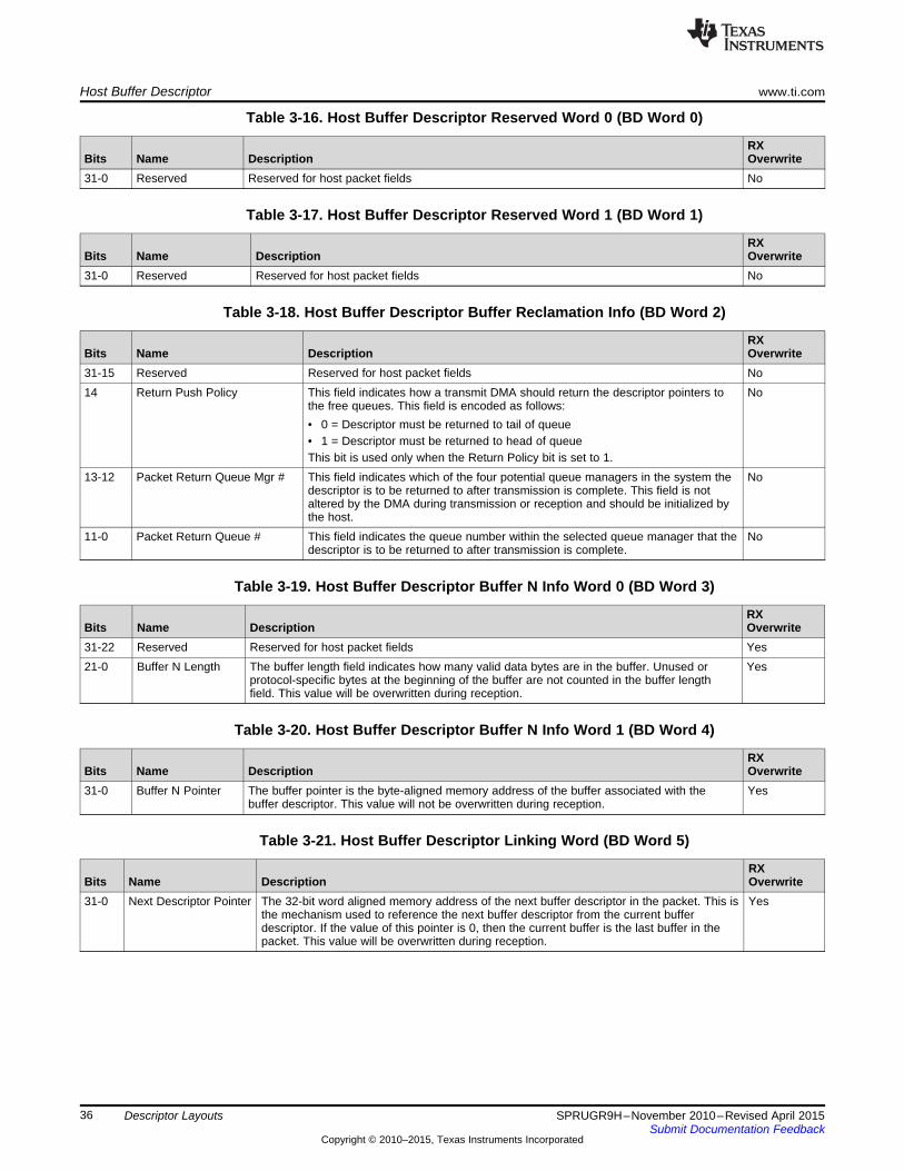
Host Buffer Descriptor www.ti.com
Table 3-16. Host Buffer Descriptor Reserved Word 0 (BD Word 0)
RXBits Name Description Overwrite31-0 Reserved Reserved for host packet fields No
Table 3-17. Host Buffer Descriptor Reserved Word 1 (BD Word 1)
RXBits Name Description Overwrite31-0 Reserved Reserved for host packet fields No
Table 3-18. Host Buffer Descriptor Buffer Reclamation Info (BD Word 2)
RXBits Name Description Overwrite31-15 Reserved Reserved for host packet fields No14 Return Push Policy This field indicates how a transmit DMA should return the descriptor pointers to No
the free queues. This field is encoded as follows:• 0 = Descriptor must be returned to tail of queue• 1 = Descriptor must be returned to head of queueThis bit is used only when the Return Policy bit is set to 1.
13-12 Packet Return Queue Mgr # This field indicates which of the four potential queue managers in the system the Nodescriptor is to be returned to after transmission is complete. This field is notaltered by the DMA during transmission or reception and should be initialized bythe host.
11-0 Packet Return Queue # This field indicates the queue number within the selected queue manager that the Nodescriptor is to be returned to after transmission is complete.
Table 3-19. Host Buffer Descriptor Buffer N Info Word 0 (BD Word 3)
RXBits Name Description Overwrite31-22 Reserved Reserved for host packet fields Yes21-0 Buffer N Length The buffer length field indicates how many valid data bytes are in the buffer. Unused or Yes
protocol-specific bytes at the beginning of the buffer are not counted in the buffer lengthfield. This value will be overwritten during reception.
Table 3-20. Host Buffer Descriptor Buffer N Info Word 1 (BD Word 4)
RXBits Name Description Overwrite31-0 Buffer N Pointer The buffer pointer is the byte-aligned memory address of the buffer associated with the Yes
buffer descriptor. This value will not be overwritten during reception.
Table 3-21. Host Buffer Descriptor Linking Word (BD Word 5)
RXBits Name Description Overwrite31-0 Next Descriptor Pointer The 32-bit word aligned memory address of the next buffer descriptor in the packet. This is Yes
the mechanism used to reference the next buffer descriptor from the current bufferdescriptor. If the value of this pointer is 0, then the current buffer is the last buffer in thepacket. This value will be overwritten during reception.
36 Descriptor Layouts SPRUGR9H–November 2010–Revised April 2015Submit Documentation Feedback
Copyright © 2010–2015, Texas Instruments Incorporated

www.ti.com Monolithic Descriptor
Table 3-22. Host Buffer Descriptor Original Buffer Info Word 0 (BD Word 6)
RXBits Name Description Overwrite31-28 Original Buffer 0 Pool This field is used to identify which pool the attached buffer was originally allocated from. No
Index This is distinct from the descriptor pool/queue index because a single buffer may bereferenced by more that one descriptor. This is a software-only field that is not touched bythe hardware.
27-22 Original Buffer 0 This field is used to indicate how many references have been made to the attached buffer NoReference Count by different descriptors. Multiple buffer references are commonly used to implement
broadcast and multicast packet forwarding when zero packet data copies are desired. Thisis a software-only field that is not touched by the hardware.
21-0 Original Buffer 0 The buffer length field indicates the original size of the buffer in bytes. Data bytes are in the NoLength buffer. This value will not be overwritten during reception. This value is read by the RX
DMA to determine the actual buffer size as allocated by the host at initialization. Becausethe buffer length in word 3 is overwritten by the RX port during reception, this field isnecessary to permanently store the buffer size information.
Table 3-23. Host Buffer Descriptor Original Buffer Info Word 1 (BD Word 7)
RXBits Name Description Overwrite31-0 Original Buffer 0 The buffer pointer is the byte-aligned memory address of the buffer associated with the No
Pointer buffer descriptor. This value will not be overwritten during reception. This value is read bythe RX DMA to determine the actual buffer location as allocated by the host at initialization.Because the buffer pointer in word 4 is overwritten by the RX port during reception, thisfield is necessary to permanently store the buffer pointer information.
3.3 Monolithic DescriptorThe monolithic packet descriptor contains the following information:• Indicator that identifies the descriptor as a monolithic packet descriptor• Source and destination tags• Packet type• Packet length• Packet error indicator• Packet return information• Protocol-specific region size• Protocol-specific region offset• Protocol-specific control / status bits• Packet data
The maximum size of a monolithic packet descriptor is 65535 bytes. Of this, monolithic packet descriptorsalways contain 12 bytes of required information and may also contain 16 bytes of software-specifictagging information and up to 128 bytes (indicated in 4-byte increments) of protocol-specific information.How much protocol-specific information (and therefore the allocated size of the descriptors) is applicationdependent. The descriptor layout is shown in Table 3-24.
37SPRUGR9H–November 2010–Revised April 2015 Descriptor LayoutsSubmit Documentation Feedback
Copyright © 2010–2015, Texas Instruments Incorporated
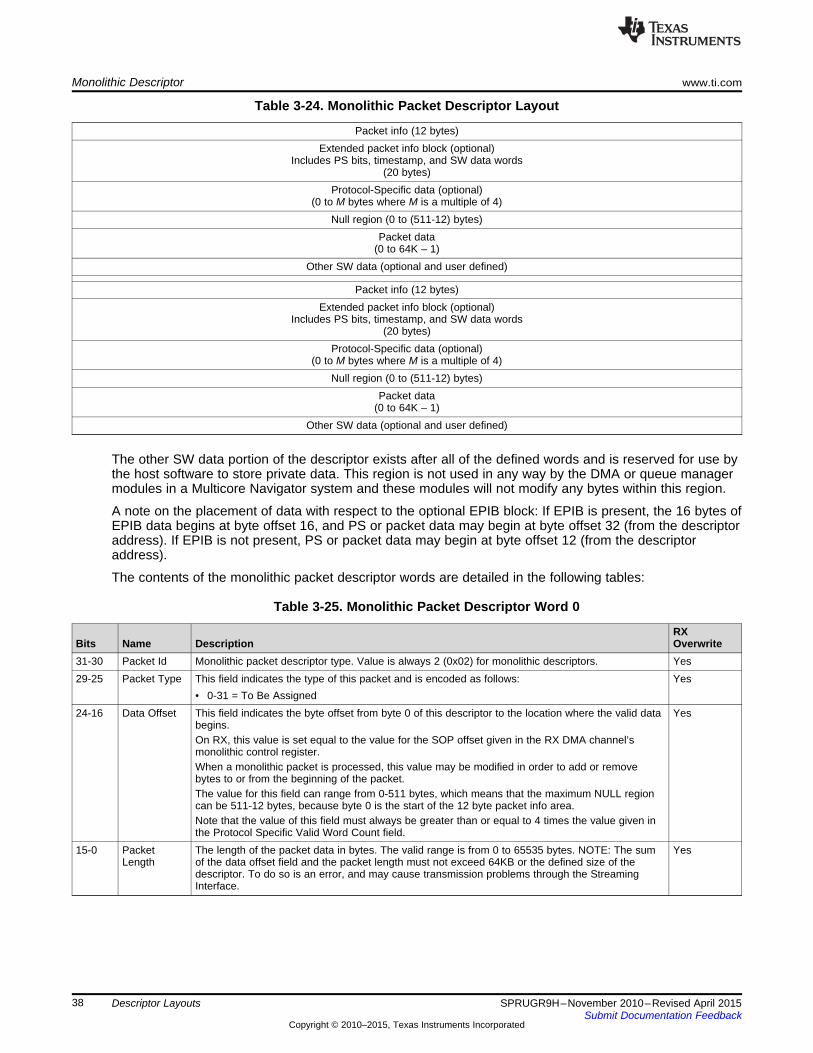
Monolithic Descriptor www.ti.com
Table 3-24. Monolithic Packet Descriptor Layout
Packet info (12 bytes)Extended packet info block (optional)
Includes PS bits, timestamp, and SW data words(20 bytes)
Protocol-Specific data (optional)(0 to M bytes where M is a multiple of 4)
Null region (0 to (511-12) bytes)Packet data
(0 to 64K – 1)Other SW data (optional and user defined)
Packet info (12 bytes)Extended packet info block (optional)
Includes PS bits, timestamp, and SW data words(20 bytes)
Protocol-Specific data (optional)(0 to M bytes where M is a multiple of 4)
Null region (0 to (511-12) bytes)Packet data
(0 to 64K – 1)Other SW data (optional and user defined)
The other SW data portion of the descriptor exists after all of the defined words and is reserved for use bythe host software to store private data. This region is not used in any way by the DMA or queue managermodules in a Multicore Navigator system and these modules will not modify any bytes within this region.
A note on the placement of data with respect to the optional EPIB block: If EPIB is present, the 16 bytes ofEPIB data begins at byte offset 16, and PS or packet data may begin at byte offset 32 (from the descriptoraddress). If EPIB is not present, PS or packet data may begin at byte offset 12 (from the descriptoraddress).
The contents of the monolithic packet descriptor words are detailed in the following tables:
Table 3-25. Monolithic Packet Descriptor Word 0
RXBits Name Description Overwrite31-30 Packet Id Monolithic packet descriptor type. Value is always 2 (0x02) for monolithic descriptors. Yes29-25 Packet Type This field indicates the type of this packet and is encoded as follows: Yes
• 0-31 = To Be Assigned24-16 Data Offset This field indicates the byte offset from byte 0 of this descriptor to the location where the valid data Yes
begins.On RX, this value is set equal to the value for the SOP offset given in the RX DMA channel’smonolithic control register.When a monolithic packet is processed, this value may be modified in order to add or removebytes to or from the beginning of the packet.The value for this field can range from 0-511 bytes, which means that the maximum NULL regioncan be 511-12 bytes, because byte 0 is the start of the 12 byte packet info area.Note that the value of this field must always be greater than or equal to 4 times the value given inthe Protocol Specific Valid Word Count field.
15-0 Packet The length of the packet data in bytes. The valid range is from 0 to 65535 bytes. NOTE: The sum YesLength of the data offset field and the packet length must not exceed 64KB or the defined size of the
descriptor. To do so is an error, and may cause transmission problems through the StreamingInterface.
38 Descriptor Layouts SPRUGR9H–November 2010–Revised April 2015Submit Documentation Feedback
Copyright © 2010–2015, Texas Instruments Incorporated

www.ti.com Monolithic Descriptor
Table 3-26. Monolithic Packet Descriptor Word 1
RXBits Name Description Overwrite31-24 Source Tag - Hi This field is application-specific. During packet reception, the DMA controller in the port will Configurable
overwrite this field as specified in the RX_SRC_TAG_HI_SEL field in the flow configurationtable entry.
23-16 Source Tag - Lo This field is application-specific. During packet reception, the DMA controller in the port will Configurableoverwrite this field as specified in the RX_SRC_TAG_LO_SEL field in the flow configurationtable entry. For TX, this value supplies the RX flow index to the streaming I/F forinfrastructure use.
15-8 Dest Tag – Hi This field is application-specific. During packet reception, the DMA controller in the port will Configurableoverwrite this field as specified in the RX_DEST_TAG_HI_SEL field in the flow configurationtable entry.
7-0 Dest Tag - Lo This field is application-specific. During packet reception, the DMA controller in the port will Configurableoverwrite this field as specified in the RX_DEST_TAG_LO_SEL field in the flow configurationtable entry.
Table 3-27. Monolithic Packet Descriptor Word 2
RXBits Name Description Overwrite31 Extended Packet This field indicates the presence of the extended packet info block in the descriptor. Yes
Info Block • 0 = EPIB is not presentPresent
• 1 = 16 byte EPIB is present30 Reserved Unused Yes29-24 Protocol Specific This field indicates the valid number of 32-bit words in the protocol-specific region. This is Yes
Valid Word Count encoded in increments of 4 bytes as follows:• 0 = 0 bytes• 1 = 4 bytes• …• 16 = 64 bytes• …• 32 = 128 bytes• 33-63 = Reserved
23-20 Error Flags This field contains error flags that can be assigned based on the packet type. Yes19-16 Protocol Specific This field contains protocol-specific flags / information that can be assigned based on the Yes
Flags packet type.15 Reserved Unused No14 Return Push This field indicates how a transmit DMA should return the descriptor pointers to the free No
Policy queues. This field is encoded as follows:• 0 = Descriptor must be returned to tail of queue• 1 = Descriptor must be returned to head of queue
13-12 Packet Return This field indicates which of the four potential queue managers in the system the descriptor is to NoQueue Mgr # be returned to after transmission is complete. This field is not altered by the DMA during
transmission or reception and should be initialized by the host.11-0 Packet Return This field indicates the queue number within the selected queue manager that the descriptor is No
Queue # to be returned to after transmission is complete.
Table 3-28. Monolithic Extended Packet NULL Word (Optional) (1)
RXBits Name Description Overwrite31-0 Reserved This field is present only to align the extended packet words to a 128-bit boundary in memory. No
This word can be used for host SW scratchpad because it will not be copied or overwritten by theDMA components.
(1) This word is present only if the Extended Packet Info Block present bit is set in word 2.
39SPRUGR9H–November 2010–Revised April 2015 Descriptor LayoutsSubmit Documentation Feedback
Copyright © 2010–2015, Texas Instruments Incorporated

Monolithic Descriptor www.ti.com
Table 3-29. Monolithic Extended Packet Info Word 0 (Optional) (1)
RXBits Name Description Overwrite31-0 Timestamp Info This field contains an application-specific timestamp that can be used for traffic shaping in a Configurable
QoS-enabled system.(1) This word is present only if the Extended Packet Info Block present bit is set in word 2.
Table 3-30. Monolithic Extended Packet Info Word 1 (Optional) (1)
RXBits Name Description Overwrite31-0 Software Info 0 This field stores software-centric information that needs to travel with the packet through the Configurable
stack. This information will be copied from the source descriptor to the destination descriptorwhenever a prefetch operation is performed or when transferring through an infrastructureDMA node.
(1) This word is present only if the Extended Packet Info Block present bit is set in word 2.
Table 3-31. Monolithic Extended Packet Info Word 2 (Optional) (1)
RXBits Name Description Overwrite31-0 Software Info 1 This field stores software-centric information that needs to travel with the packet through the Configurable
stack. This information will be copied from the source descriptor to the destination descriptorwhenever a prefetch operation is performed or when transferring through an infrastructureDMA node.
(1) This word is present only if the Extended Packet Info Block present bit is set in word 2.
Table 3-32. Monolithic Extended Packet Info Word 3 (Optional) (1)
RXBits Name Description Overwrite31-0 Software Info 2 This field stores software-centric information that needs to travel with the packet through Configurable
the stack. This information will be copied from the source descriptor to the destinationdescriptor whenever a prefetch operation is performed or when transferring through aninfrastructure DMA node.
(1) This word is present only if the Extended Packet Info Block present bit is set in word 2.
Table 3-33. Monolithic Packet Descriptor Protocol Specific Word M (Optional) (1)
RXBits Name Description Overwrite31-0 Protocol Specific Data N This field stores information that varies depending on the packet type. Configurable
(1) These words, if present, immediately follow the software data block information.
Table 3-34. Monolithic Packet Descriptor Payload Data Words 0-N (1) (2)
RXBits Name Description Overwrite31-0 Packet Data N These words store the packet payload data. Yes
(1) The payload data follows the protocol-specific words at an offset specified in the data offset field of word 0.(2) This field is endian-specific. In other words, this is the only field in the descriptor that changes based on the endianess of the system.
40 Descriptor Layouts SPRUGR9H–November 2010–Revised April 2015Submit Documentation Feedback
Copyright © 2010–2015, Texas Instruments Incorporated

www.ti.com Monolithic Descriptor
41SPRUGR9H–November 2010–Revised April 2015 Descriptor LayoutsSubmit Documentation Feedback
Copyright © 2010–2015, Texas Instruments Incorporated

Chapter 4SPRUGR9H–November 2010–Revised April 2015
Registers
The following sections describe the memory mapped registers within each region of the Queue ManagerSub-system and PKTDMA. All Multicore Navigator registers support 32-bit accesses only.
Topic ........................................................................................................................... Page
4.1 Queue Manager.................................................................................................. 434.2 Packet DMA ....................................................................................................... 624.3 QMSS PDSPs..................................................................................................... 834.4 QMSS Interrupt Distributor ................................................................................ 104
42 Registers SPRUGR9H–November 2010–Revised April 2015Submit Documentation Feedback
Copyright © 2010–2015, Texas Instruments Incorporated
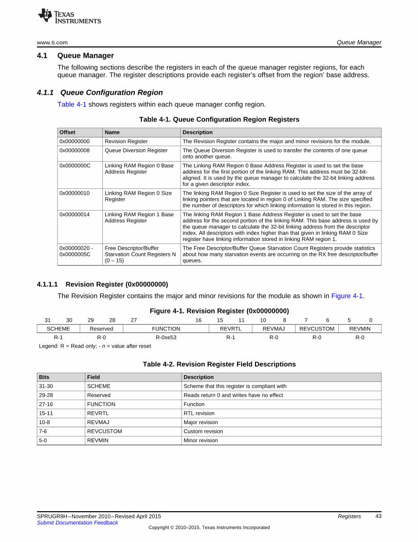
www.ti.com Queue Manager
4.1 Queue ManagerThe following sections describe the registers in each of the queue manager register regions, for eachqueue manager. The register descriptions provide each register’s offset from the region’ base address.
4.1.1 Queue Configuration RegionTable 4-1 shows registers within each queue manager config region.
Table 4-1. Queue Configuration Region Registers
Offset Name Description0x00000000 Revision Register The Revision Register contains the major and minor revisions for the module.0x00000008 Queue Diversion Register The Queue Diversion Register is used to transfer the contents of one queue
onto another queue.0x0000000C Linking RAM Region 0 Base The Linking RAM Region 0 Base Address Register is used to set the base
Address Register address for the first portion of the linking RAM. This address must be 32-bit-aligned. It is used by the queue manager to calculate the 32-bit linking addressfor a given descriptor index.
0x00000010 Linking RAM Region 0 Size The linking RAM Region 0 Size Register is used to set the size of the array ofRegister linking pointers that are located in region 0 of Linking RAM. The size specified
the number of descriptors for which linking information is stored in this region.0x00000014 Linking RAM Region 1 Base The linking RAM Region 1 Base Address Register is used to set the base
Address Register address for the second portion of the linking RAM. This base address is used bythe queue manager to calculate the 32-bit linking address from the descriptorindex. All descriptors with index higher than that given in linking RAM 0 Sizeregister have linking information stored in linking RAM region 1.
0x00000020 - Free Descriptor/Buffer The Free Descriptor/Buffer Queue Starvation Count Registers provide statistics0x0000005C Starvation Count Registers N about how many starvation events are occurring on the RX free descriptor/buffer
(0 – 15) queues.
4.1.1.1 Revision Register (0x00000000)The Revision Register contains the major and minor revisions for the module as shown in Figure 4-1.
Figure 4-1. Revision Register (0x00000000)31 30 29 28 27 16 15 11 10 8 7 6 5 0SCHEME Reserved FUNCTION REVRTL REVMAJ REVCUSTOM REVMIN
R-1 R-0 R-0xe53 R-1 R-0 R-0 R-0Legend: R = Read only; - n = value after reset
Table 4-2. Revision Register Field Descriptions
Bits Field Description31-30 SCHEME Scheme that this register is compliant with29-28 Reserved Reads return 0 and writes have no effect27-16 FUNCTION Function15-11 REVRTL RTL revision10-8 REVMAJ Major revision7-6 REVCUSTOM Custom revision5-0 REVMIN Minor revision
43SPRUGR9H–November 2010–Revised April 2015 RegistersSubmit Documentation Feedback
Copyright © 2010–2015, Texas Instruments Incorporated
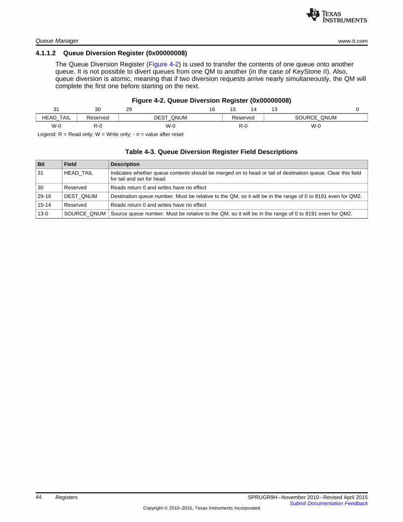
Queue Manager www.ti.com
4.1.1.2 Queue Diversion Register (0x00000008)The Queue Diversion Register (Figure 4-2) is used to transfer the contents of one queue onto anotherqueue. It is not possible to divert queues from one QM to another (in the case of KeyStone II). Also,queue diversion is atomic, meaning that if two diversion requests arrive nearly simultaneously, the QM willcomplete the first one before starting on the next.
Figure 4-2. Queue Diversion Register (0x00000008)31 30 29 16 15 14 13 0
HEAD_TAIL Reserved DEST_QNUM Reserved SOURCE_QNUMW-0 R-0 W-0 R-0 W-0
Legend: R = Read only; W = Write only; - n = value after reset
Table 4-3. Queue Diversion Register Field Descriptions
Bit Field Description31 HEAD_TAIL Indicates whether queue contents should be merged on to head or tail of destination queue. Clear this field
for tail and set for head.30 Reserved Reads return 0 and writes have no effect29-16 DEST_QNUM Destination queue number. Must be relative to the QM, so it will be in the range of 0 to 8191 even for QM2.15-14 Reserved Reads return 0 and writes have no effect13-0 SOURCE_QNUM Source queue number. Must be relative to the QM, so it will be in the range of 0 to 8191 even for QM2.
44 Registers SPRUGR9H–November 2010–Revised April 2015Submit Documentation Feedback
Copyright © 2010–2015, Texas Instruments Incorporated
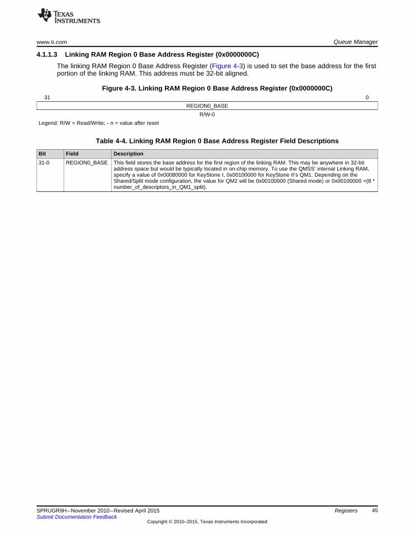
www.ti.com Queue Manager
4.1.1.3 Linking RAM Region 0 Base Address Register (0x0000000C)The linking RAM Region 0 Base Address Register (Figure 4-3) is used to set the base address for the firstportion of the linking RAM. This address must be 32-bit aligned.
Figure 4-3. Linking RAM Region 0 Base Address Register (0x0000000C)31 0
REGION0_BASER/W-0
Legend: R/W = Read/Write; - n = value after reset
Table 4-4. Linking RAM Region 0 Base Address Register Field Descriptions
Bit Field Description31-0 REGION0_BASE This field stores the base address for the first region of the linking RAM. This may be anywhere in 32-bit
address space but would be typically located in on-chip memory. To use the QMSS’ internal Linking RAM,specify a value of 0x00080000 for KeyStone I, 0x00100000 for KeyStone II’s QM1. Depending on theShared/Split mode configuration, the value for QM2 will be 0x00100000 (Shared mode) or 0x00100000 +(8 *number_of_descriptors_in_QM1_split).
45SPRUGR9H–November 2010–Revised April 2015 RegistersSubmit Documentation Feedback
Copyright © 2010–2015, Texas Instruments Incorporated
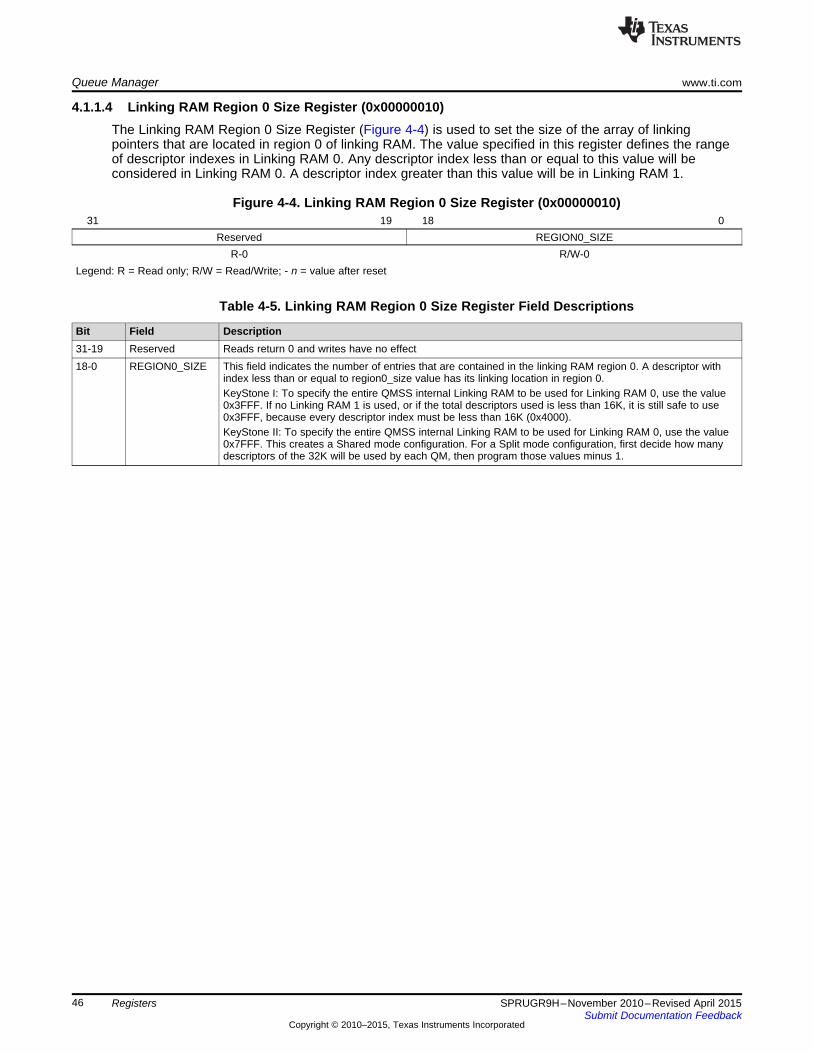
Queue Manager www.ti.com
4.1.1.4 Linking RAM Region 0 Size Register (0x00000010)The Linking RAM Region 0 Size Register (Figure 4-4) is used to set the size of the array of linkingpointers that are located in region 0 of linking RAM. The value specified in this register defines the rangeof descriptor indexes in Linking RAM 0. Any descriptor index less than or equal to this value will beconsidered in Linking RAM 0. A descriptor index greater than this value will be in Linking RAM 1.
Figure 4-4. Linking RAM Region 0 Size Register (0x00000010)31 19 18 0
Reserved REGION0_SIZER-0 R/W-0
Legend: R = Read only; R/W = Read/Write; - n = value after reset
Table 4-5. Linking RAM Region 0 Size Register Field Descriptions
Bit Field Description31-19 Reserved Reads return 0 and writes have no effect18-0 REGION0_SIZE This field indicates the number of entries that are contained in the linking RAM region 0. A descriptor with
index less than or equal to region0_size value has its linking location in region 0.KeyStone I: To specify the entire QMSS internal Linking RAM to be used for Linking RAM 0, use the value0x3FFF. If no Linking RAM 1 is used, or if the total descriptors used is less than 16K, it is still safe to use0x3FFF, because every descriptor index must be less than 16K (0x4000).KeyStone II: To specify the entire QMSS internal Linking RAM to be used for Linking RAM 0, use the value0x7FFF. This creates a Shared mode configuration. For a Split mode configuration, first decide how manydescriptors of the 32K will be used by each QM, then program those values minus 1.
46 Registers SPRUGR9H–November 2010–Revised April 2015Submit Documentation Feedback
Copyright © 2010–2015, Texas Instruments Incorporated
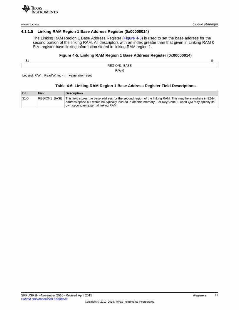
www.ti.com Queue Manager
4.1.1.5 Linking RAM Region 1 Base Address Register (0x00000014)The Linking RAM Region 1 Base Address Register (Figure 4-5) is used to set the base address for thesecond portion of the linking RAM. All descriptors with an index greater than that given in Linking RAM 0Size register have linking information stored in linking RAM region 1.
Figure 4-5. Linking RAM Region 1 Base Address Register (0x00000014)31 0
REGION1_BASER/W-0
Legend: R/W = Read/Write; - n = value after reset
Table 4-6. Linking RAM Region 1 Base Address Register Field Descriptions
Bit Field Description31-0 REGION1_BASE This field stores the base address for the second region of the linking RAM. This may be anywhere in 32-bit
address space but would be typically located in off-chip memory. For KeyStone II, each QM may specify itsown secondary external linking RAM.
47SPRUGR9H–November 2010–Revised April 2015 RegistersSubmit Documentation Feedback
Copyright © 2010–2015, Texas Instruments Incorporated
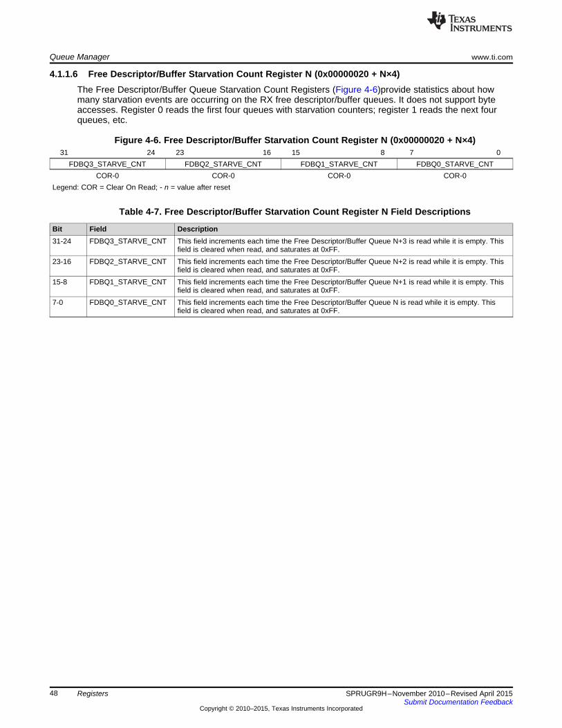
Queue Manager www.ti.com
4.1.1.6 Free Descriptor/Buffer Starvation Count Register N (0x00000020 + N×4)The Free Descriptor/Buffer Queue Starvation Count Registers (Figure 4-6)provide statistics about howmany starvation events are occurring on the RX free descriptor/buffer queues. It does not support byteaccesses. Register 0 reads the first four queues with starvation counters; register 1 reads the next fourqueues, etc.
Figure 4-6. Free Descriptor/Buffer Starvation Count Register N (0x00000020 + N×4)31 24 23 16 15 8 7 0
FDBQ3_STARVE_CNT FDBQ2_STARVE_CNT FDBQ1_STARVE_CNT FDBQ0_STARVE_CNTCOR-0 COR-0 COR-0 COR-0
Legend: COR = Clear On Read; - n = value after reset
Table 4-7. Free Descriptor/Buffer Starvation Count Register N Field Descriptions
Bit Field Description31-24 FDBQ3_STARVE_CNT This field increments each time the Free Descriptor/Buffer Queue N+3 is read while it is empty. This
field is cleared when read, and saturates at 0xFF.23-16 FDBQ2_STARVE_CNT This field increments each time the Free Descriptor/Buffer Queue N+2 is read while it is empty. This
field is cleared when read, and saturates at 0xFF.15-8 FDBQ1_STARVE_CNT This field increments each time the Free Descriptor/Buffer Queue N+1 is read while it is empty. This
field is cleared when read, and saturates at 0xFF.7-0 FDBQ0_STARVE_CNT This field increments each time the Free Descriptor/Buffer Queue N is read while it is empty. This
field is cleared when read, and saturates at 0xFF.
48 Registers SPRUGR9H–November 2010–Revised April 2015Submit Documentation Feedback
Copyright © 2010–2015, Texas Instruments Incorporated
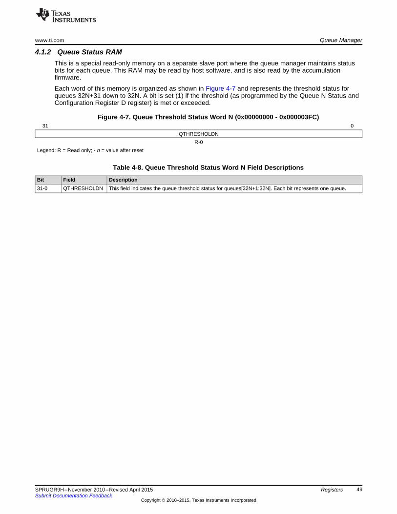
www.ti.com Queue Manager
4.1.2 Queue Status RAMThis is a special read-only memory on a separate slave port where the queue manager maintains statusbits for each queue. This RAM may be read by host software, and is also read by the accumulationfirmware.
Each word of this memory is organized as shown in Figure 4-7 and represents the threshold status forqueues 32N+31 down to 32N. A bit is set (1) if the threshold (as programmed by the Queue N Status andConfiguration Register D register) is met or exceeded.
Figure 4-7. Queue Threshold Status Word N (0x00000000 - 0x000003FC)31 0
QTHRESHOLDNR-0
Legend: R = Read only; - n = value after reset
Table 4-8. Queue Threshold Status Word N Field Descriptions
Bit Field Description31-0 QTHRESHOLDN This field indicates the queue threshold status for queues[32N+1:32N]. Each bit represents one queue.
49SPRUGR9H–November 2010–Revised April 2015 RegistersSubmit Documentation Feedback
Copyright © 2010–2015, Texas Instruments Incorporated

Queue Manager www.ti.com
4.1.3 Descriptor Memory Setup RegionThe registers in this region program one of the queue manager’s descriptor memory regions.
NOTE: Software must assure that all three Descriptor Memory Setup Region registers are initializedprior to pushing and popping descriptors addressed in the region. If modifying a single regionduring runtime, it is good practice to write a zero to the Memory Region R Base AddressRegister first when disabling the region, and last (with a valid global address) when enablingthe region.
Table 4-9. Descriptor Memory Setup Region Registers
Offset Name Description0x00000000 + Memory Region R Base The Memory Region R Base Address Register is written by the host to set
Address Register (0...19, or the base address of memory region R. This memory region will store a16 × R0...63 for KeyStone II) number of descriptors of a particular size as determined by the Memory
Region R Control Register.0x00000004 + Memory Region R Start Index The Memory Region R Start Index Register is written by the host to
Register (0...19, or 0...63 for configure index of the first descriptor in this memory region.16 × RKeyStone II)
0x00000008 + Memory Region R Descriptor The Memory Region R Descriptor Setup Register is written by the host toSetup Register (0...19, or configure various descriptor related parameters of this memory region.16 × R0...63 for KeyStone II)
NOTE: Memory regions and packet descriptors must be aligned to 16 byte boundaries. Forperformance reasons, it is preferable to align descriptors and data buffers to 64 byteboundaries if they are larger than 32 bytes. This allows data to flow through the chip with thefewest bus transactions.
4.1.3.1 Memory Region R Base Address Register (0x00000000 + 16×R)The Memory Region R Base Address Register (Figure 4-8) is written by the host to set the base addressof memory region R. This memory region will store a number of descriptors of a particular size asdetermined by the Memory Region R Control Register. Note: In KeyStone I, memory region baseaddresses must be set in ascending order, i.e. region 0 must be at a lower address than region 1, region 1must be at a lower address than region 2, etc. In KeyStone II, this restriction is removed, and memoryregions need not be programmed in order (i.e. you can program regions 1, 2, 3, 5, and not 4).
Figure 4-8. Memory Region R Base Address Register (0x00000000 + 16×R)31 0
REGR_BASR/W-0
Legend: R/W = Read/Write; - n = value after reset
Table 4-10. Memory Region R Base Address Register Field Descriptions
Bit Field Description31-0 REGR_BASE This field contains the base address of the memory region R.
50 Registers SPRUGR9H–November 2010–Revised April 2015Submit Documentation Feedback
Copyright © 2010–2015, Texas Instruments Incorporated
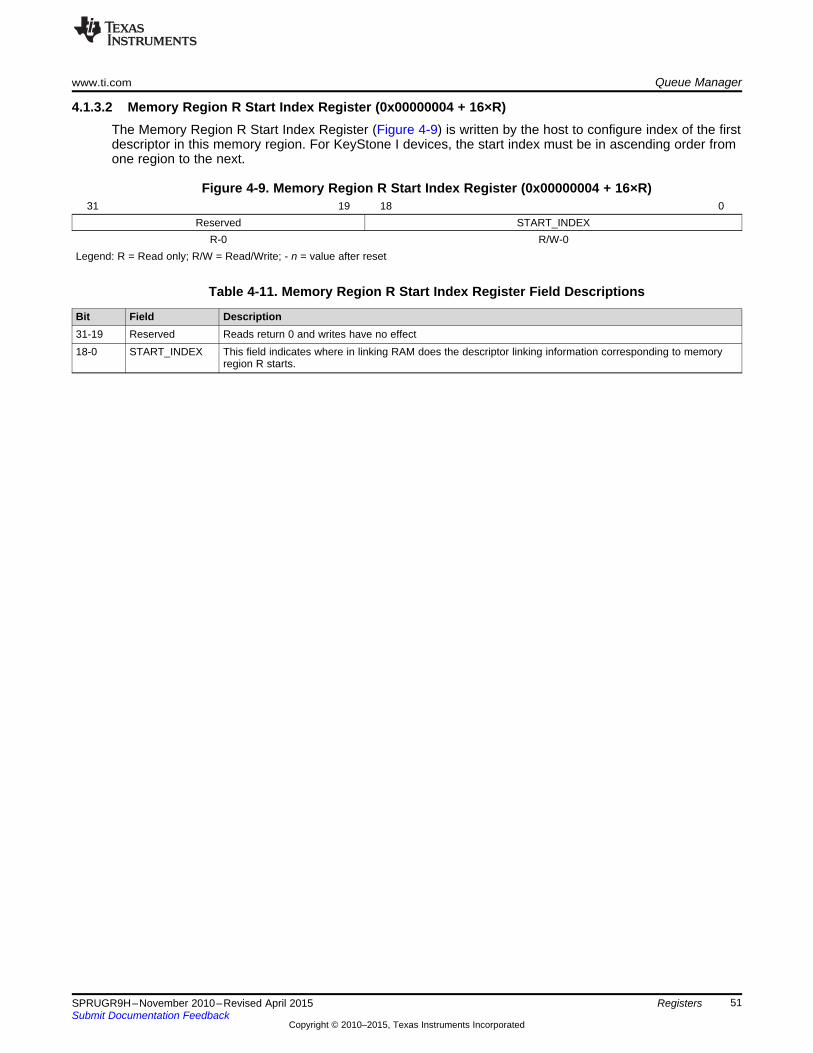
www.ti.com Queue Manager
4.1.3.2 Memory Region R Start Index Register (0x00000004 + 16×R)The Memory Region R Start Index Register (Figure 4-9) is written by the host to configure index of the firstdescriptor in this memory region. For KeyStone I devices, the start index must be in ascending order fromone region to the next.
Figure 4-9. Memory Region R Start Index Register (0x00000004 + 16×R)31 19 18 0
Reserved START_INDEXR-0 R/W-0
Legend: R = Read only; R/W = Read/Write; - n = value after reset
Table 4-11. Memory Region R Start Index Register Field Descriptions
Bit Field Description31-19 Reserved Reads return 0 and writes have no effect18-0 START_INDEX This field indicates where in linking RAM does the descriptor linking information corresponding to memory
region R starts.
51SPRUGR9H–November 2010–Revised April 2015 RegistersSubmit Documentation Feedback
Copyright © 2010–2015, Texas Instruments Incorporated
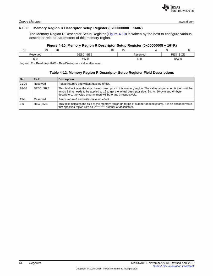
Queue Manager www.ti.com
4.1.3.3 Memory Region R Descriptor Setup Register (0x00000008 + 16×R)The Memory Region R Descriptor Setup Register (Figure 4-10) is written by the host to configure variousdescriptor-related parameters of this memory region.
Figure 4-10. Memory Region R Descriptor Setup Register (0x00000008 + 16×R)31 29 28 16 15 4 3 0
Reserved DESC_SIZE Reserved REG_SIZER-0 R/W-0 R-0 R/W-0
Legend: R = Read only; R/W = Read/Write; - n = value after reset
Table 4-12. Memory Region R Descriptor Setup Register Field Descriptions
Bit Field Description31-29 Reserved Reads return 0 and writes have no effect.28-16 DESC_SIZE This field indicates the size of each descriptor in this memory region. The value programmed is the multiplier
minus 1 that needs to be applied to 16 to get the actual descriptor size. So, for 16-byte and 64-bytedescriptors, the value programmed will be 0 and 3 respectively.
15-4 Reserved Reads return 0 and writes have no effect.3-0 REG_SIZE This field indicates the size of the memory region (in terms of number of descriptors). It is an encoded value
that specifies region size as 2(5+reg_size) number of descriptors.
52 Registers SPRUGR9H–November 2010–Revised April 2015Submit Documentation Feedback
Copyright © 2010–2015, Texas Instruments Incorporated

www.ti.com Queue Manager
4.1.4 Queue Management/Queue Proxy RegionsThe registers in these regions are used to push descriptors into queues, to pop descriptors from queues,and to retrieve information from queues.
Table 4-13. Queue Management/Proxy Region Registers
Offset Name Description0x00000000 + 16×N Queue N Register A The Queue N Register A is an optional register that is implemented only for a queue
if the queue supports entry / byte count feature. The entry count feature provides a(0 – 8191)count of the number of entries that are currently valid in the queue.
0x00000004 + 16×N Queue N Register B The Queue N Register B is an optional register that is implemented only for a queueif the queue supports a total byte count feature. The total byte count feature provides(0 – 8191)a count of the total number of bytes in all of the packets that are currently valid in thequeue. This register must be read prior to reading Queue N Register D duringpacket pop operation if the total size information is desired.
0x00000008 + 16×N Queue N Register C The Queue N Register C is used to provide additional information about the packetthat is being pushed or popped from the queue. This register provides an option for(0 – 8191)the packet to be pushed onto either the tail of the queue (default) or the head of thequeue (override). This register must be written prior to writing the Queue N registerD during packet write operations. This register must be read prior to reading QueueN register D during pop operations if the packet size information is desired.
0x0000000C + 16×N Queue N Register D The Queue N Register D is written to add a packet to the queue and read to pop apacket off a queue. The packet is pushed or popped to/from the queue only when(0 – 8191)the Queue Register D is written.
NOTE: There are three sets of Registers A, B, C, and D (for all 8191 queues), one set in each of thefollowing QMSS regions: Queue Management, Queue Proxy and Queue Peek. Thefunctioning of these registers is different in each region. See Section 4.1.5 for details on theQueue Peek registers.
The following sections describe each of the four register locations that are present for each queue in theseregions. For reasons of implementation and area efficiency, these registers are not actually implementedas a huge array of flip flops but are instead implemented as a single set of mailbox registers that use theLSBs of the provided address as a queue index. Because of this implementation, all accesses to theseregisters need to be performed as a single burst write for each packet add or a single burst read for eachpacket pop operation. For host (user application) access, this requires writing to the Queue Proxy regionto ensure atomicity. The length of a burst to add or pop a packet will vary depending on the optionalfeatures that the queue supports, which may be 4, 8, 12, or 16 bytes. Queue N Register D must always bewritten / read in the burst, but the preceding words are optional depending on the required queuefunctionality.
NOTE: If a program reads or writes Registers A, B, or C in the Queue Management region or writesto the Queue Proxy region without also reading/writing Register D, the hardware assumes animplied read/write to Register D, and the queue will be popped/pushed. This can causeunpredictable results, because either the popped descriptor address will be lost, or anunknown value (or 0) may be pushed. The problem reduces to Registers C and D, becauseRegisters A and B are read-only and should almost always be read from the Queue Peekregion.
53SPRUGR9H–November 2010–Revised April 2015 RegistersSubmit Documentation Feedback
Copyright © 2010–2015, Texas Instruments Incorporated

Queue Manager www.ti.com
4.1.4.1 Queue N Register A (0x00000000 + 16×N)The Queue N Register A (Figure 4-11) provides an entry count feature, which is a count of the number ofdescriptors currently contained in the queue.
Figure 4-11. Queue N Register A (0x00000000 + 16×N)31 19 18 0
Reserved QUEUE_ENTRY_COUNTR-0 R-0
Legend: R = Read only; - n = value after reset
Table 4-14. Queue N Register A Field Descriptions
Bit Field Description31-19 Reserved Reads return 0 and writes have no effect.18-0 QUEUE_ENTRY_COUNT This field indicates how many packets (descriptors) are currently queued on the queue. This
count is incremented by 1 whenever a packet is added to the queue. This count is decrementedby 1 whenever a packet is popped from the queue. Do not read this register unless you alsointend on popping the queue with Reg D. To obtain the descriptor count without also poppingthe queue, use Queue N Status and Configuration Reg A in the Queue Peek region.
54 Registers SPRUGR9H–November 2010–Revised April 2015Submit Documentation Feedback
Copyright © 2010–2015, Texas Instruments Incorporated

www.ti.com Queue Manager
4.1.4.2 Queue N Register B (0x00000004 + 16×N)The Queue N Register B (Figure 4-12) provides a byte count feature, which is the sum of the Queue NRegister C PACKET_SIZE fields of all packets that are currently contained in the queue. This registermust be read prior to reading Queue N Register D during packet pop operation if the byte countinformation is desired. Note, this is a saturating 32-bit counter.
Figure 4-12. Queue N Register B (0x00000004 + 16×N)31 0
QUEUE_BYTE_COUNTR-0
Legend: R = Read only; - n = value after reset
Table 4-15. Queue N Register B Field Descriptions
Bit Field Description31-0 QUEUE_BYTE_COUNT This field indicates the sum of all PACKET_SIZE fields that are currently pushed to this queue. The
sum is increased with a push and decreased with a pop. Pushes MUST include writing to Queue NRegister C or this sum will remain zero. Do not read this register unless you also intend on poppingthe queue with Reg D. To obtain the byte count without also popping the queue, use Queue N Statusand Configuration Reg B in the Queue Peek region.
55SPRUGR9H–November 2010–Revised April 2015 RegistersSubmit Documentation Feedback
Copyright © 2010–2015, Texas Instruments Incorporated

Queue Manager www.ti.com
4.1.4.3 Queue N Register C (0x00000008 + 16×N)The Queue N Register C (Figure 4-13) is used to provide additional information about the packet that isbeing pushed or popped from the queue. This register provides an option for the packet to be pushed ontoeither the tail of the queue (the default) or the head of the queue. This register must be written prior towriting the Queue N Register D during packet write (push) operations. This register must be read prior toreading Queue N Register D during pop operations if the packet size information is desired.
NOTE: Do not read this register in the Queue Management region, and do not read/write thisregister without also reading/writing Register D, because in either case, an implied pop/pushwill result. Register C must be part of an atomic write to the queue. This can beaccomplished by writing to the Queue Proxy region or the VBUSM (DMA port) address rangeshown in Table 4-1. An atomic write to the DMA port requires a 64 bit type to be written toReg. C (the 64 bit variable contains both Reg C and Reg D values).
Figure 4-13. Queue N Register C (0x00000008 + 16×N)31 30 17 16 0
HEAD_TAIL Reserved PACKET_SIZEW-0 R-0 R/W-0
Legend: R = Read only; W = Write only; R/W = Read/Write; - n = value after reset
Table 4-16. Queue N Register C Field Descriptions
Bit Field Description31 HEAD_TAIL Head/tail push control. Set to 0 to push packet onto tail of queue and set to 1 to push packet onto head of
queue.30-17 Reserved Reads return 0 and writes have no effect.16-0 PACKET_SIZE This field indicates the packet size and is assumed to be zero unless a non-zero value is given. This field
can be the total packet size, just the payload size, or some other value if desired. The QM simply sumsthese values for each push, and reports the current sum when Queue N Register B is read.
56 Registers SPRUGR9H–November 2010–Revised April 2015Submit Documentation Feedback
Copyright © 2010–2015, Texas Instruments Incorporated

www.ti.com Queue Manager
4.1.4.4 Queue N Register D (0x0000000C + 16×N)The Queue N Register D (Figure 4-14) is written to add a packet to the queue and read to pop a packetoff a queue. The packet is pushed to or popped from the queue only when the Queue Register D iswritten.
NOTE: Remember that all accesses to Registers A, B, C and D are considered by the hardware anatomic access. If reading/writing Register C with this register, read the atomicity note in thesection for Register C. Reading Registers A and B are best done using the Queue Peekregion. Please see the above register descriptions for more information. Pushing to theVBUSM address is faster than the VBUSP address due to the deeper write buffer (and nostalls), but popping is faster via the VBUSP address to due the higher VBUSM SCR latencyfor pop operations.
Figure 4-14. Queue N Register D (0x0000000C + 16×N)31 4 3 0
DESC_PTR DESC_SIZER/W-0 R/W-0
Legend: R/W = Read/Write; - n = value after reset
Table 4-17. Queue N Register D Field Descriptions
Bit Field Description31-4 DESC_PTR Descriptor pointer. It will be read as 0 if the queue is empty. It will indicate a 16-byte-aligned address that
points to a descriptor when the queue is not empty. Writing a 0 will force queue empty, possibly losingqueued descriptors.
3-0 DESC_SIZE Descriptor hint size (PKTDMA pre-fetch size), encoded in 16-byte increments as follows:• 0 = 16 bytes• 1 = 32 bytes• 2 = 48 bytes• ...• 15 = 256 bytes.This field should be set to the smallest value that is greater than or equal to the size of the entire controlportion of the descriptor. This includes all descriptor information (including the protocol specific bytes) withthe exception of the data portion of the monolithic descriptor. If this value is smaller than the control portionsize of the descriptor, the PKTDMA will not fetch the remainder and will hang. For AIF Monolithic Mode, thisvalue should always be set to 3. If the queue is empty, this field will return a 0x0 when read.When the Packet DMA pushes descriptors to TX Return queues, this field will be 0. When it pushes to RXDestination queues, it will be set based on the constructed descriptor.
CAUTIONA race condition may occur whenever a program writes to two differing memoryendpoints, meaning that the memory writes are not guaranteed to land in theorder written. When the write to push to a PKTDMA Tx queue immediatelyfollows a write to another endpoint (such as a descriptor or payload data), thePKTDMA could start reading the data before it has actually landed. This can bemitigated by adding an MFENCE instruction prior to the push.
57SPRUGR9H–November 2010–Revised April 2015 RegistersSubmit Documentation Feedback
Copyright © 2010–2015, Texas Instruments Incorporated

Queue Manager www.ti.com
4.1.5 Queue Peek RegionThe registers in this region are used get the descriptor and byte counts of queues, and to set the queuethresholds for TX queues that drive select TX DMA channels in Multicore Navigator peripherals.
NOTE: This region may be write protected by MPU2 (a Memory Protection Unit) depending on theversion of boot used. For more information, see the Memory Protection Unit (MPU) forKeyStone Devices User Guide (SPRUGW5).
Table 4-18. Queue Peek Region Registers
Offset Name Description0x00000000 + 16×N Queue N Status and This is an optional register that is implemented only for a queue if the
Configuration Register A queue supports entry/byte count feature. The entry count feature providesa count of the number of entries that are currently valid in the queue.(0 – 8191)
0x00000004 + 16×N Queue N Status and This is an optional register that is implemented only for a queue if theConfiguration Register B queue supports a total byte count feature. The total byte count feature
provides a count of the total number of bytes in all of the packets that are(0 – 8191)currently valid in the queue.
0x00000008 + 16×N Queue N Status and This register specifies the packet size for the head element of a queue.Configuration Register C(0 – 8191)
0x0000000C + 16×N Queue N Status and This register is used to configure the queue threshold feature. WhenConfiguration Register D enabled, the queue threshold pin (for select TX queues) gets asserted
when the number of items in a queue is above or below a threshold value.(0 – 8191)This register is available for each queue.
4.1.5.1 Queue N Status and Configuration Register A (0x00000000 + 16×N)The Queue N Status and Configuration Register A (Figure 4-15) is an optional register that is implementedonly for a queue if the queue supports entry/byte count feature. The entry count feature provides a countof the number of entries that are currently valid in the queue.
Figure 4-15. Queue N Status and Configuration Register A (0x00000000 + 16×N)31 19 18 0
Reserved QUEUE_ENTRY_COUNTR-0 R-0
Legend: R = Read only; - n = value after reset
Table 4-19. Queue N Status and Configuration Register A Field Descriptions
Bit Field Description31-19 Reserved Reads return 0 and writes have no effect.18-0 QUEUE_ENTRY_COUNT This field indicates how many packets are currently queued on the queue.
58 Registers SPRUGR9H–November 2010–Revised April 2015Submit Documentation Feedback
Copyright © 2010–2015, Texas Instruments Incorporated

www.ti.com Queue Manager
4.1.5.2 Queue N Status and Configuration Register B (0x00000004 + 16×N)The Queue N Status and Configuration Register B (Figure 4-16) is an optional register that is implementedonly for a queue if the queue supports a total byte count feature. The total byte count feature provides acount of the total number of bytes in all of the packets that are currently valid in the queue.
Figure 4-16. Queue N Status and Configuration Register B (0x00000004 + 16×N)31 0
QUEUE_BYTE_COUNTR-0
Legend: R = Read only; - n = value after reset
Table 4-20. Queue N Status and Configuration Register B Field Descriptions
Bit Field Description31-0 QUEUE_BYTE_COUNT This field indicates how many bytes total are contained in all of the packets that are currently
queued on this queue.
59SPRUGR9H–November 2010–Revised April 2015 RegistersSubmit Documentation Feedback
Copyright © 2010–2015, Texas Instruments Incorporated

Queue Manager www.ti.com
4.1.5.3 Queue N Status and Configuration Register C (0x00000008 + 16×N)The Queue N Status and Configuration Register C (Figure 4-17) specifies the packet size for the headelement of a queue, if a value was written (via Queue N Register C) when the element was pushed. It is 0otherwise.
Figure 4-17. Queue N Status and Configuration Register C (0x00000008 + 16×N)31 17 16 0
Reserved PACKET_SIZER-0 R-0
Legend: R = Read only; - n = value after reset
Table 4-21. Queue N Status and Configuration Register C Field Descriptions
Bit Field Description31-17 Reserved Reads return 0 and writes have no effect.16-0 PACKET_SIZE This field indicates packet size of the head element of a queue.
60 Registers SPRUGR9H–November 2010–Revised April 2015Submit Documentation Feedback
Copyright © 2010–2015, Texas Instruments Incorporated

www.ti.com Queue Manager
4.1.5.4 Queue N Status and Configuration Register D (0x0000000C + 16×N)The Queue N Status and Configuration Register D (Figure 4-18) is used to configure the queue thresholdfeature. When enabled, the Queue Status RAM is updated with each push and pop. This register isavailable for all queues. Also, because the accumulation firmware reads the Queue Status RAM, theseregisters must be programmed for all queues used by the accumulator, with the value 0x81, which willcause the status bit to set on non-zero count, and clear on zero.
NOTE: This register is write protected by MPU2 (Memory Protection Unit). See the MemoryProtection Unit (MPU) for KeyStone Devices User Guide (SPRUGW5) for details on how togrant write access.
Figure 4-18. Queue N Status and Configuration Register D (0x0000000C + 16×N)31 8 7 6 4 3 0
Reserved THRESHOLD_HILO Reserved THRESHOLDR-0 R/W-1 R-0 R/W-1
Legend: R = Read only; R/W = Read/Write; - n = value after reset
Table 4-22. Queue N Status and Configuration Register D Field Descriptions
Bit Field Description31-8 Reserved Reads return 0 and writes have no effect.7 THRESHOLD_HILO This field indicates whether the number of items in a queue should be greater than, equal to, or less
than the threshold before the QUEUE_ECNT_STATUS[queue] bit is asserted. If this field is set, thenthe status bit is set (1) when the size of the queue is at least as big as the set threshold value. If thisbit is cleared, then the status bit is set (1) when the size of the queue is less than the set thresholdvalue.
6-4 Reserved Reads return 0 and writes have no effect.3-0 THRESHOLD This field indicates the threshold at which the queue threshold bit is set. This field is internally
represented as a ten bit number. The threshold is 0 when this field is 0. The threshold is 0x3FF whenit is 10 or higher. It is (2threshold - 1) in the internal representation for other values.
61SPRUGR9H–November 2010–Revised April 2015 RegistersSubmit Documentation Feedback
Copyright © 2010–2015, Texas Instruments Incorporated

Packet DMA www.ti.com
4.2 Packet DMAThe following sections describe the registers in each of the Packet DMA’s register regions.
Each PKTDMA supports a unique number of channels and flow configurations appropriate for its use (seeChapter 5 for details). The counts of channels and flows determine the addressable size of the registerregion.
4.2.1 Global Control Registers RegionThe PKTDMA Global Control Registers region, which configure items not related to channels or flows. Theaddress map for this region is shown in Table 4-23:
Table 4-23. PKTDMA Global Control Region Registers
Byte Address Name0x00 Revision Register0x04 Performance Control Register0x08 Emulation Control Register0x0C Priority Control Register0x10 QM0 Base Address Register0x14 QM1 Base Address Register0x18 QM2 Base Address Register0x1C QM3 Base Address Register
4.2.1.1 Revision Register (0x00)The Revision Register (Figure 4-19) contains the major and minor revisions for the module.
Figure 4-19. Revision Register (0x00)31 30 29 16 15 11 10 8 7 0Reserved MODID REVRTL REVMAJ REVMIN
R-0 R-0x4E5A R-1 R-0x1 R-0Legend: R = Read only; - n = value after reset;
Table 4-24. Revision Register Field Descriptions
Bit Field Description31-30 Reserved Reads return 0 and writes have no effect.29-16 MODID Module ID field15-11 REVRTL RTL revision. Will vary depending on release.10-8 REVMAJ Major revision.7-0 REVMIN Minor revision.
62 Registers SPRUGR9H–November 2010–Revised April 2015Submit Documentation Feedback
Copyright © 2010–2015, Texas Instruments Incorporated

www.ti.com Packet DMA
4.2.1.2 Performance Control Register (0x04)The Performance Control Register (Figure 4-20) is used to adjust the performance of the PKTDMA in thesystem.
Figure 4-20. Performance Control Register (0x04)31 22 21 16 15 0
Reserved WARB_FIFO_DEPTH TIMEOUTR-0 R/W-0x20 R/W-0
Legend: R = Read only; R/W = Read/Write; - n = value after reset
Table 4-25. Performance Control Register Field Descriptions
Bit Field Description31-22 Reserved Reads return 0 and writes have no effect.21-16 WARB_FIFO_DEPTH This field sets the depth of the write arbitration FIFO, which stores write transaction information
between the command arbiter and write data arbiters in the Bus Interface Unit. This value can beset to a range of 1 to 32. Setting this field to smaller values will prevent the PKTDMA from havingan excess of write transactions outstanding whose data is still waiting to be transferred. Systemperformance can suffer if write commands are allowed to be issued long before the correspondingwrite data will be transferred. This field allows the command count to be optimized based on systemdynamics.
15-0 TIMEOUT This field sets a timeout duration in clock cycles. It controls the minimum amount of time that an RXchannel will be required to wait when it encounters a buffer starvation condition and the RX errorhandling bit is set to 1 (packet is to be preserved - no discard). If the RX error handling bit in theflow table is cleared, this field will have no effect on the RX operation. When this field is set to 0, theRX engine will not force an RX channel to wait after encountering a starvation event (the feature isdisabled). When this field is set to a value other than 0, the RX engine will force any channel whoseassociated flow had the RX error handling bit asserted and which encounters starvation to wait forat least the specified # of clock cycles before coming into context again to retry the access to theQM. This is intended to control potentially debilitating effects on the QM performance that can becaused by the PKTDMA modules continually polling the QM. The exact number of clock cyclesbetween QM access attempts is not important and will not be exact. The number of cycles waitedwill be at least as large as TIMEOUT.
63SPRUGR9H–November 2010–Revised April 2015 RegistersSubmit Documentation Feedback
Copyright © 2010–2015, Texas Instruments Incorporated
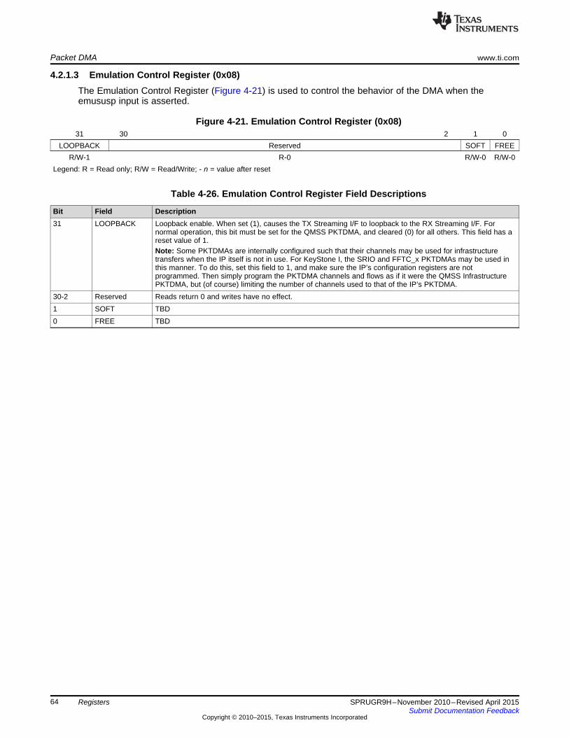
Packet DMA www.ti.com
4.2.1.3 Emulation Control Register (0x08)The Emulation Control Register (Figure 4-21) is used to control the behavior of the DMA when theemususp input is asserted.
Figure 4-21. Emulation Control Register (0x08)31 30 2 1 0
LOOPBACK Reserved SOFT FREER/W-1 R-0 R/W-0 R/W-0
Legend: R = Read only; R/W = Read/Write; - n = value after reset
Table 4-26. Emulation Control Register Field Descriptions
Bit Field Description31 LOOPBACK Loopback enable. When set (1), causes the TX Streaming I/F to loopback to the RX Streaming I/F. For
normal operation, this bit must be set for the QMSS PKTDMA, and cleared (0) for all others. This field has areset value of 1.Note: Some PKTDMAs are internally configured such that their channels may be used for infrastructuretransfers when the IP itself is not in use. For KeyStone I, the SRIO and FFTC_x PKTDMAs may be used inthis manner. To do this, set this field to 1, and make sure the IP’s configuration registers are notprogrammed. Then simply program the PKTDMA channels and flows as if it were the QMSS InfrastructurePKTDMA, but (of course) limiting the number of channels used to that of the IP’s PKTDMA.
30-2 Reserved Reads return 0 and writes have no effect.1 SOFT TBD0 FREE TBD
64 Registers SPRUGR9H–November 2010–Revised April 2015Submit Documentation Feedback
Copyright © 2010–2015, Texas Instruments Incorporated
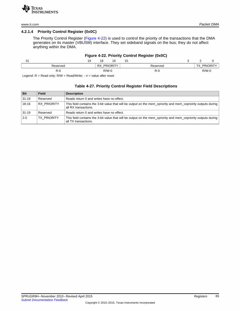
www.ti.com Packet DMA
4.2.1.4 Priority Control Register (0x0C)The Priority Control Register (Figure 4-22) is used to control the priority of the transactions that the DMAgenerates on its master (VBUSM) interface. They set sideband signals on the bus; they do not affectanything within the DMA.
Figure 4-22. Priority Control Register (0x0C)31 19 18 16 15 3 2 0
Reserved RX_PRIORITY Reserved TX_PRIORITYR-0 R/W-0 R-0 R/W-0
Legend: R = Read only; R/W = Read/Write; - n = value after reset
Table 4-27. Priority Control Register Field Descriptions
Bit Field Description31-19 Reserved Reads return 0 and writes have no effect.18-16 RX_PRIORITY This field contains the 3-bit value that will be output on the mem_cpriority and mem_cepriority outputs during
all RX transactions.31-19 Reserved Reads return 0 and writes have no effect.2-0 TX_PRIORITY This field contains the 3-bit value that will be output on the mem_cpriority and mem_cepriority outputs during
all TX transactions.
65SPRUGR9H–November 2010–Revised April 2015 RegistersSubmit Documentation Feedback
Copyright © 2010–2015, Texas Instruments Incorporated
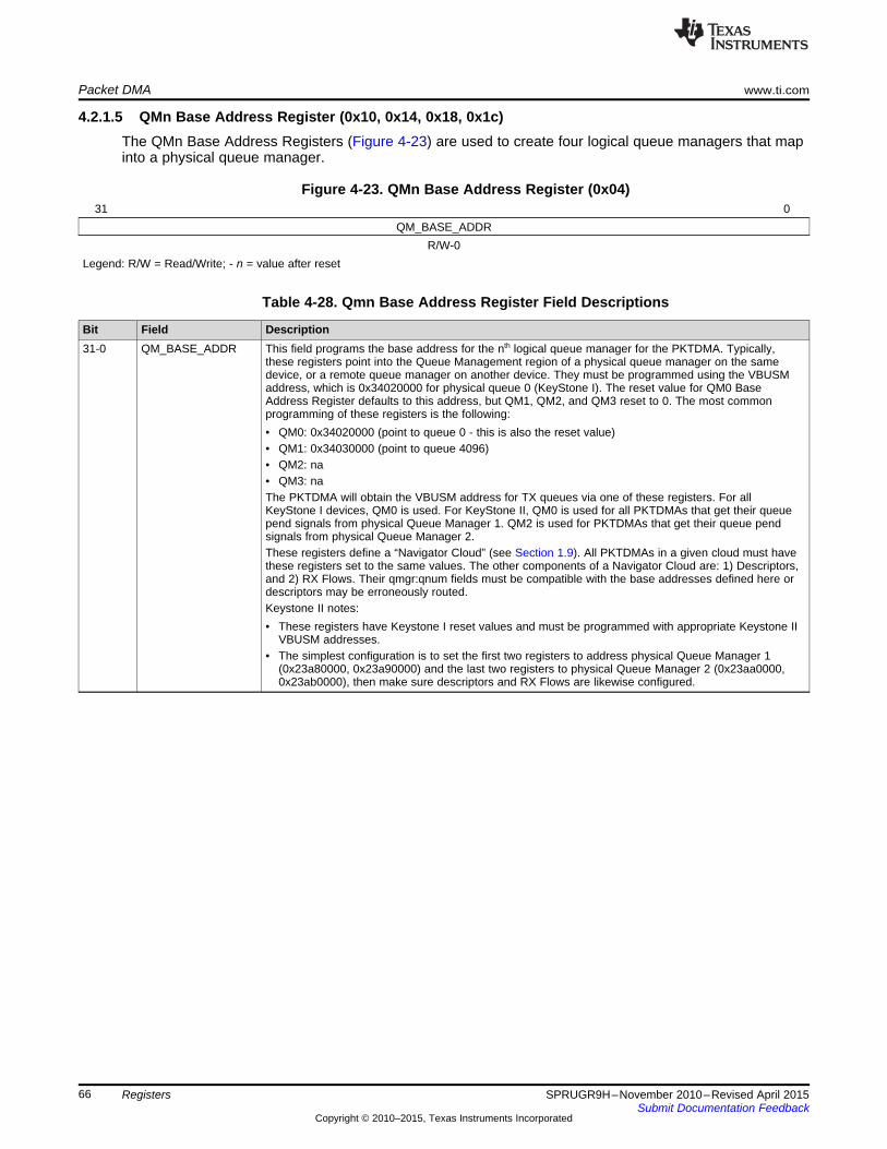
Packet DMA www.ti.com
4.2.1.5 QMn Base Address Register (0x10, 0x14, 0x18, 0x1c)The QMn Base Address Registers (Figure 4-23) are used to create four logical queue managers that mapinto a physical queue manager.
Figure 4-23. QMn Base Address Register (0x04)31 0
QM_BASE_ADDRR/W-0
Legend: R/W = Read/Write; - n = value after reset
Table 4-28. Qmn Base Address Register Field Descriptions
Bit Field Description31-0 QM_BASE_ADDR This field programs the base address for the nth logical queue manager for the PKTDMA. Typically,
these registers point into the Queue Management region of a physical queue manager on the samedevice, or a remote queue manager on another device. They must be programmed using the VBUSMaddress, which is 0x34020000 for physical queue 0 (KeyStone I). The reset value for QM0 BaseAddress Register defaults to this address, but QM1, QM2, and QM3 reset to 0. The most commonprogramming of these registers is the following:• QM0: 0x34020000 (point to queue 0 - this is also the reset value)• QM1: 0x34030000 (point to queue 4096)• QM2: na• QM3: naThe PKTDMA will obtain the VBUSM address for TX queues via one of these registers. For allKeyStone I devices, QM0 is used. For KeyStone II, QM0 is used for all PKTDMAs that get their queuepend signals from physical Queue Manager 1. QM2 is used for PKTDMAs that get their queue pendsignals from physical Queue Manager 2.These registers define a “Navigator Cloud” (see Section 1.9). All PKTDMAs in a given cloud must havethese registers set to the same values. The other components of a Navigator Cloud are: 1) Descriptors,and 2) RX Flows. Their qmgr:qnum fields must be compatible with the base addresses defined here ordescriptors may be erroneously routed.Keystone II notes:• These registers have Keystone I reset values and must be programmed with appropriate Keystone II
VBUSM addresses.• The simplest configuration is to set the first two registers to address physical Queue Manager 1
(0x23a80000, 0x23a90000) and the last two registers to physical Queue Manager 2 (0x23aa0000,0x23ab0000), then make sure descriptors and RX Flows are likewise configured.
66 Registers SPRUGR9H–November 2010–Revised April 2015Submit Documentation Feedback
Copyright © 2010–2015, Texas Instruments Incorporated

www.ti.com Packet DMA
4.2.2 TX DMA Channel Configuration RegionThis region is used to configure the TX DMA channels. The memory map for the TX DMA ChannelConfiguration Region is shown in Table 4-29:
Table 4-29. TX DMA Channel Config Region Registers
Address Register0x000 TX Channel 0 Global Configuration Register A0x004 TX Channel 0 Global Configuration Register B0x008 – 0x01F Reserved0x020 TX Channel 1 Global Configuration Register A0x024 TX Channel 1 Global Configuration Register B0x028 – 0x03F Reserved0x000 + N × 32 TX Channel N Global Configuration Register A0x004 + N × 32 TX Channel N Global Configuration Register B0x008 + N × 32 Reserved
67SPRUGR9H–November 2010–Revised April 2015 RegistersSubmit Documentation Feedback
Copyright © 2010–2015, Texas Instruments Incorporated
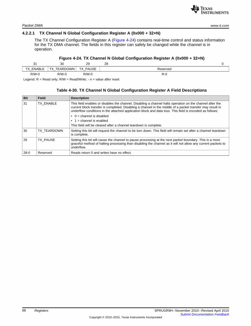
Packet DMA www.ti.com
4.2.2.1 TX Channel N Global Configuration Register A (0x000 + 32×N)The TX Channel Configuration Register A (Figure 4-24) contains real-time control and status informationfor the TX DMA channel. The fields in this register can safely be changed while the channel is inoperation.
Figure 4-24. TX Channel N Global Configuration Register A (0x000 + 32×N)31 30 29 28 0
TX_ENABLE TX_TEARDOWN TX_PAUSE ReservedR/W-0 R/W-0 R/W-0 R-0
Legend: R = Read only; R/W = Read/Write; - n = value after reset
Table 4-30. TX Channel N Global Configuration Register A Field Descriptions
Bit Field Description31 TX_ENABLE This field enables or disables the channel. Disabling a channel halts operation on the channel after the
current block transfer is completed. Disabling a channel in the middle of a packet transfer may result inunderflow conditions in the attached application block and data loss. This field is encoded as follows:• 0 = channel is disabled• 1 = channel is enabledThis field will be cleared after a channel teardown is complete.
30 TX_TEARDOWN Setting this bit will request the channel to be torn down. This field will remain set after a channel teardownis complete.
29 TX_PAUSE Setting this bit will cause the channel to pause processing at the next packet boundary. This is a moregraceful method of halting processing than disabling the channel as it will not allow any current packets tounderflow.
28-0 Reserved Reads return 0 and writes have no effect.
68 Registers SPRUGR9H–November 2010–Revised April 2015Submit Documentation Feedback
Copyright © 2010–2015, Texas Instruments Incorporated
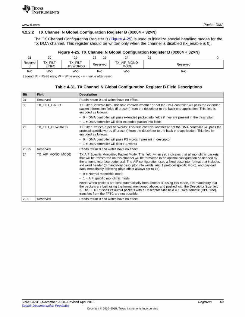
www.ti.com Packet DMA
4.2.2.2 TX Channel N Global Configuration Register B (0x004 + 32×N)The TX Channel Configuration Register B (Figure 4-25) is used to initialize special handling modes for theTX DMA channel. This register should be written only when the channel is disabled (tx_enable is 0).
Figure 4-25. TX Channel N Global Configuration Register B (0x004 + 32×N)31 30 29 28 25 24 23 0
Reserve TX_FILT TX_FILT TX_AIF_MONOReserved Reservedd _EINFO _PSWORDS _MODER-0 W-0 W-0 R-0 W-0 R-0
Legend: R = Read only; W = Write only; - n = value after reset
Table 4-31. TX Channel N Global Configuration Register B Field Descriptions
Bit Field Description31 Reserved Reads return 0 and writes have no effect.30 TX_FILT_EINFO TX Filter Software Info: This field controls whether or not the DMA controller will pass the extended
packet information fields (if present) from the descriptor to the back end application. This field isencoded as follows:• 0 = DMA controller will pass extended packet info fields if they are present in the descriptor• 1 = DMA controller will filter extended packet info fields
29 TX_FILT_PSWORDS TX Filter Protocol Specific Words: This field controls whether or not the DMA controller will pass theprotocol specific words (if present) from the descriptor to the back end application. This field isencoded as follows:• 0 = DMA controller will pass PS words if present in descriptor• 1 = DMA controller will filter PS words
28-25 Reserved Reads return 0 and writes have no effect.24 TX_AIF_MONO_MODE TX AIF Specific Monolithic Packet Mode: This field, when set, indicates that all monolithic packets
that will be transferred on this channel will be formatted in an optimal configuration as needed bythe antenna interface peripheral. The AIF configuration uses a fixed descriptor format that includesa 4 word header (3 mandatory descriptor info words, and 1 protocol specific word), and payloaddata immediately following (data offset always set to 16).• 0 = Normal monolithic mode• 1 = AIF specific monolithic modeNote: When packets are sent automatically from another IP using this mode, it is mandatory thatthe packets are built using the format mentioned above, and pushed with the Descriptor Size field =3. The FFTC pushes its output packets with a Descriptor Size field = 1, so automatic (CPU free)transfers from the FFTC are not possible.
23-0 Reserved Reads return 0 and writes have no effect.
69SPRUGR9H–November 2010–Revised April 2015 RegistersSubmit Documentation Feedback
Copyright © 2010–2015, Texas Instruments Incorporated

Packet DMA www.ti.com
4.2.3 RX DMA Channel Configuration RegionThis region is used to configure the RX DMA channels. The memory map for the RX DMA ChannelConfiguration Region is shown in Table 4-32:
Table 4-32. RX DMA Channel Config Region Registers
Address Register0x00 RX Channel 0 Global Configuration Register A0x04 – 0x1F Reserved0x20 RX Channel 1 Global Configuration Register A0x24 – 0x3F Reserved0x00 + N×32 RX Channel N Global Configuration Register A0x04 + N×32 Reserved
4.2.3.1 RX Channel N Global Configuration Register A (0x000 + 32×N)The RX Channel Configuration Register A (Figure 4-26) contains real-time control and status informationfor the RX DMA channel. The fields in this register can safely be changed while the channel is inoperation.
Figure 4-26. RX Channel N Global Configuration Register A (0x000 + 32×N)31 30 29 28 0
RX_ENABLE RX_TEARDOWN RX_PAUSE ReservedR/W-0 R/W-0 R/W-0 R-0
Legend: R = Read only; R/W = Read/Write; - n = value after reset
Table 4-33. RX Channel N Global Configuration Register A Field Descriptions
Bit Field Description31 RX_ENABLE This field enables or disables the channel. Disabling a channel halts operation on the channel after the
current block transfer is completed. Disabling a channel in the middle of a packet transfer may result inoverflow conditions in the attached application and data loss. This field is encoded as follows:• 0 = channel is disabled• 1 = channel is enabledThis field will be cleared after a channel teardown is complete. If the host is enabling a channel that is justbeing set up, the host must initialize all of the other channel configuration fields before setting this bit.
30 RX_TEARDOWN This field indicates whether or not an RX teardown operation is complete. This field should be cleared whena channel is initialized. This field will be set after a channel teardown is complete.
29 RX_PAUSE Setting this bit will cause the channel to pause processing at the next packet boundary. This is a moregraceful method of halting processing than disabling the channel as it will not allow any current packets tooverflow.
28-0 Reserved Reads return 0 and writes have no effect.
70 Registers SPRUGR9H–November 2010–Revised April 2015Submit Documentation Feedback
Copyright © 2010–2015, Texas Instruments Incorporated

www.ti.com Packet DMA
4.2.4 RX DMA Flow Configuration RegionThis region is used to configure RX Flows. The memory map for the RX Flow Configuration RegistersRegion is shown in Table 4-34:
Table 4-34. RX DMA Flow Config Region Registers
Address Register0x000 RX Flow 0 Configuration Register A0x004 RX Flow 0 Configuration Register B0x008 RX Flow 0 Configuration Register C0x00C RX Flow 0 Configuration Register D0x010 RX Flow 0 Configuration Register E0x014 RX Flow 0 Configuration Register F0x018 RX Flow 0 Configuration Register G0x01C RX Flow 0 Configuration Register H… …0x00 + N×32 RX Flow N Configuration Register A0x04 + N×32 RX Flow N Configuration Register B0x08 + N×32 RX Flow N Configuration Register C0x0C + N×32 RX Flow N Configuration Register D0x10 + N×32 RX Flow N Configuration Register E0x14 + N×32 RX Flow N Configuration Register F0x18 + N×32 RX Flow N Configuration Register G0x1C + N×32 RX Flow N Configuration Register H
NOTE: RX Flows are used with the global QMn Base Address Registers (Section 4.2.1.5) to definea Navigator Cloud. This means that the qmgr:qnum fields in the RX Flow registers must becompatible with the QMn Base Address Register values for the PKTDMAs in the given cloud.
71SPRUGR9H–November 2010–Revised April 2015 RegistersSubmit Documentation Feedback
Copyright © 2010–2015, Texas Instruments Incorporated

Packet DMA www.ti.com
4.2.4.1 RX Flow N Configuration Register A (0x000 + 32×N)The RX Flow N Configuration Register A contains static configuration information for the RX DMA flow.The fields in this register can be safely changed only when all of the DMA channels that use this flow havebeen disabled. The fields in this register are shown in Figure 4-27:
Figure 4-27. RX Flow N Configuration Register A (0x000 + 32×N)31 30 29 28 27 26 25
Reserved RX_EINFO_PRESENT RX_PSINFO RX_ERROR RX_DESC RX_PS_PRESENT _HANDLING _TYPE _LOCATION
W-0 W-0 W-0 W-0 W-0 W-024 16 15 14 13 12 11 0
RX_SOP_OFFSET Reserved RX_DEST RX_DEST_QNUM_QMGR
W-0 W-0 W-0 W-0Legend: W = Write only; - n = value after reset
Table 4-35. RX Flow N Configuration Register A Field Descriptions
Bit Field Description31 Reserved • Reads return 0 and writes have no effect.30 RX_EINFO_PRESENT RX Extended Packet Data Block Present: This bit controls whether or not the extended packet info
block (EPIB) will be present in the RX packet descriptor.• 0 = The port DMA will clear the EPIB Present bit in the PD and will drop any EPIB data words that
are presented from the back end application.• 1 = The port DMA will set the EPIB Present bit in the PD and will copy any EPIB data words that are
presented across the RX streaming interface into the EPIB words in the descriptor. If no EPIB wordsare presented from the back end application, the port DMA will overwrite the fields with 0s.
29 RX_PSINFO_PRESENT RX Protocol Specific Words Present: This bit controls whether or not the protocol specific words will bepresent in the RX packet descriptor.• 0 = The port DMA will set the PS word count to 0 in the PD and will drop any PS words that are
presented from the back end application.• 1 = The port DMA will set the PS word count to the value given by the back end application and will
copy the PS words from the back end application to the location specified by RX_PS_LOCATION.28 RX_ERROR_HANDLING RX Error Handling Mode: This bit controls the error handling mode for the flow and is used only when
channel errors (i.e. descriptor or buffer starvation) occurs:• 0 = Starvation errors result in dropping packet and reclaiming any used descriptor or buffer resources
back to the original queues/pools they were allocated to.• 1 = Starvation errors result in subsequent re-try of the descriptor allocation operation. In this mode,
the DMA will save its internal operational state back to the internal state RAM without issuing anadvance operation to its internal FIFO buffers. This results in the DMA re-initiating the data transfer atthe time specified in the TIMEOUT field of the Performance Control Register with the intention thatadditional free buffers and/or descriptors will be added.
27-26 RX_DESC_TYPE RX Descriptor Type: This field indicates the descriptor type to use:• 0 = Host• 1 = Reserved• 2 = Monolithic• 3 = Reserved
25 RX_PS_LOCATION RX Protocol Specific Location: This bit controls where the protocol-specific words will be placed in thehost mode data structure.• 0 = The DMA will clear the protocol specific region location bit in the PD and will place the protocol-
specific words at the end of the packet descriptor.• 1 = The DMA will set the protocol specific region location bit in the PD and will place the protocol
specific words at the beginning of the data buffer. When this mode is used, it is required that theresulting target data buffer pointer (which is calculated by adding the host_rx_sop_offset to theoriginal buffer pointer in the packet descriptor) is aligned to a 32-bit boundary to avoid unwantedbuffer truncation as the DMA will round up to the next 32-bit aligned boundary.
72 Registers SPRUGR9H–November 2010–Revised April 2015Submit Documentation Feedback
Copyright © 2010–2015, Texas Instruments Incorporated
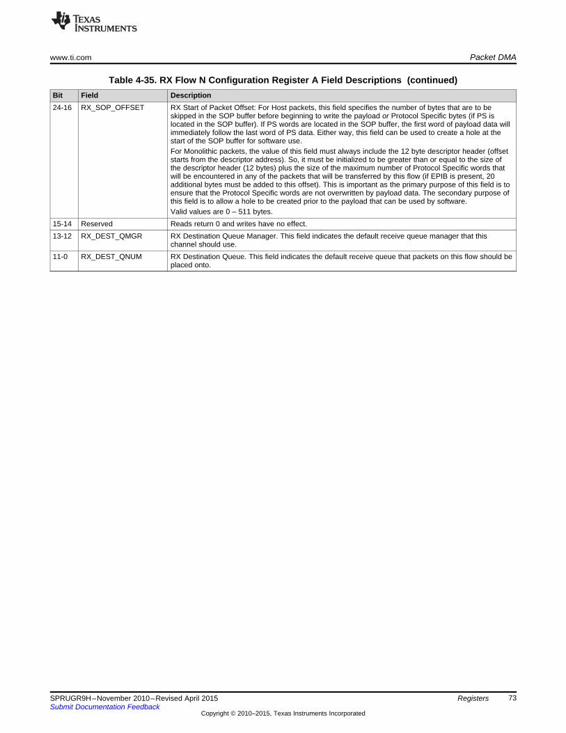
www.ti.com Packet DMA
Table 4-35. RX Flow N Configuration Register A Field Descriptions (continued)Bit Field Description24-16 RX_SOP_OFFSET RX Start of Packet Offset: For Host packets, this field specifies the number of bytes that are to be
skipped in the SOP buffer before beginning to write the payload or Protocol Specific bytes (if PS islocated in the SOP buffer). If PS words are located in the SOP buffer, the first word of payload data willimmediately follow the last word of PS data. Either way, this field can be used to create a hole at thestart of the SOP buffer for software use.For Monolithic packets, the value of this field must always include the 12 byte descriptor header (offsetstarts from the descriptor address). So, it must be initialized to be greater than or equal to the size ofthe descriptor header (12 bytes) plus the size of the maximum number of Protocol Specific words thatwill be encountered in any of the packets that will be transferred by this flow (if EPIB is present, 20additional bytes must be added to this offset). This is important as the primary purpose of this field is toensure that the Protocol Specific words are not overwritten by payload data. The secondary purpose ofthis field is to allow a hole to be created prior to the payload that can be used by software.Valid values are 0 – 511 bytes.
15-14 Reserved Reads return 0 and writes have no effect.13-12 RX_DEST_QMGR RX Destination Queue Manager. This field indicates the default receive queue manager that this
channel should use.11-0 RX_DEST_QNUM RX Destination Queue. This field indicates the default receive queue that packets on this flow should be
placed onto.
73SPRUGR9H–November 2010–Revised April 2015 RegistersSubmit Documentation Feedback
Copyright © 2010–2015, Texas Instruments Incorporated

Packet DMA www.ti.com
4.2.4.2 RX Flow N Configuration Register B (0x004 + 32×N)The RX Flow N Configuration Register B contains static configuration information for the RX DMA flow.The fields in this register can be safely changed only when all of the DMA channels that use this flow havebeen disabled. The fields in this register are shown in Figure 4-28:
Figure 4-28. RX Flow N Configuration Register B (0x004 + 32×N)31 24 23 16 15 8 7 0
RX_SRC_TAG_HI RX_SRC_TAG_LO RX_DEST_TAG_HI RX_DEST_TAG_LOW-0 W-0 W-0 W-0
Legend: W = Write only; - n = value after reset
Table 4-36. RX Flow N Configuration Register B Field Descriptions
Bit Field Description31-24 RX_SRC_TAG_HI RX Source Tag High Byte Constant Value: This is the value to insert into bits 15-8 of the source tag if the
RX_SRC_TAG_HI_SEL is set to 1.23-16 RX_SRC_TAG_LO RX Source Tag Low Byte Constant Value: This is the value to insert into bits 7-0 of the source tag if the
RX_SRC_TAG_LO_SEL is set to 1.15-8 RX_DEST_TAG_HI RX Destination Tag High Byte Constant Value: This is the value to insert into bits 15-8 of the destination
tag if the RX_DEST_TAG_HI_SEL is set to 1.7-0 RX_DEST_TAG_LO RX Destination Tag Low Byte Constant Value: This is the value to insert into bits 7-0 of the destination tag
if the RX_DEST_TAG_LO_SEL is set to 1.
74 Registers SPRUGR9H–November 2010–Revised April 2015Submit Documentation Feedback
Copyright © 2010–2015, Texas Instruments Incorporated

www.ti.com Packet DMA
4.2.4.3 RX Flow N Configuration Register C (0x008 + 32×N)The RX Flow N Configuration Register C contains static configuration information for the RX DMA flow.The fields in this register can be safely changed only when all of the DMA channels that use this flow havebeen disabled. The fields in this register are shown in Figure 4-29:
Figure 4-29. RX Flow N Configuration Register C (0x008 + 32×N)31 30 28 27 26 24 23 22 20
Reserved RX_SRC_TAG_HI_SEL Reserved RX_SRC_TAG_LO_SEL Reserved RX_DEST_TAG_HI_SELR-0 W-0 R-0 W-0 R-0 W-019 18 16 15 3 2 0
Reserved RX_DEST_TAG_LO_SEL Reserved RX_SIZE_THRESH_ENR-0 W-0 R-0 W-0
Legend: R = Read only; W = Write only; - n = value after reset
Table 4-37. RX Flow N Configuration Register C Field Descriptions
Bit Field Description31 Reserved Reads return 0 and writes have no effect.30-28 RX_SRC_TAG_HI_SEL RX source tag high byte selector. This field specifies the source for bits 31-24 of the source tag field
in the output packet descriptor. This field is encoded as follows:• 0 = Do not overwrite• 1 = Overwrite with value given in RX_SRC_TAG_HI• 2 = Overwrite with flow_id from back end application• 3 = Reserved• 4 = Overwrite with src_tag from back end application• 5 = Reserved• 6-7 = Reserved
27 Reserved Reads return 0 and writes have no effect.26-24 RX_SRC_TAG_LO_SEL RX source tag low byte selector. This field specifies the source for bits 23-16 of the source tag field
in the output packet descriptor. This field is encoded as follows:• 0 = Do not overwrite• 1 = Overwrite with value given in RX_SRC_TAG_LO• 2 = Overwrite with flow_id from back end application• 3 = Reserved• 4 = Overwrite with src_tag from back end application• 5 = Reserved• 6-7 = Reserved
23 Reserved Reads return 0 and writes have no effect.22-20 RX_DEST_TAG_HI_SEL RX destination tag high byte selector. This field specifies the source for bits 15-8 of the source tag
field in the word 1 of the output PD. This field is encoded as follows:• 0 = Do not overwrite• 1 = Overwrite with value given in RX_DEST_TAG_HI• 2 = Overwrite with flow_id from back end application• 3 = Reserved• 4 = Overwrite with dest_tag[7-0] from back end application• 5 = Overwrite with dest_tag[15-8] from back end application• 6-7 = Reserved
19 Reserved Reads return 0 and writes have no effect.
75SPRUGR9H–November 2010–Revised April 2015 RegistersSubmit Documentation Feedback
Copyright © 2010–2015, Texas Instruments Incorporated
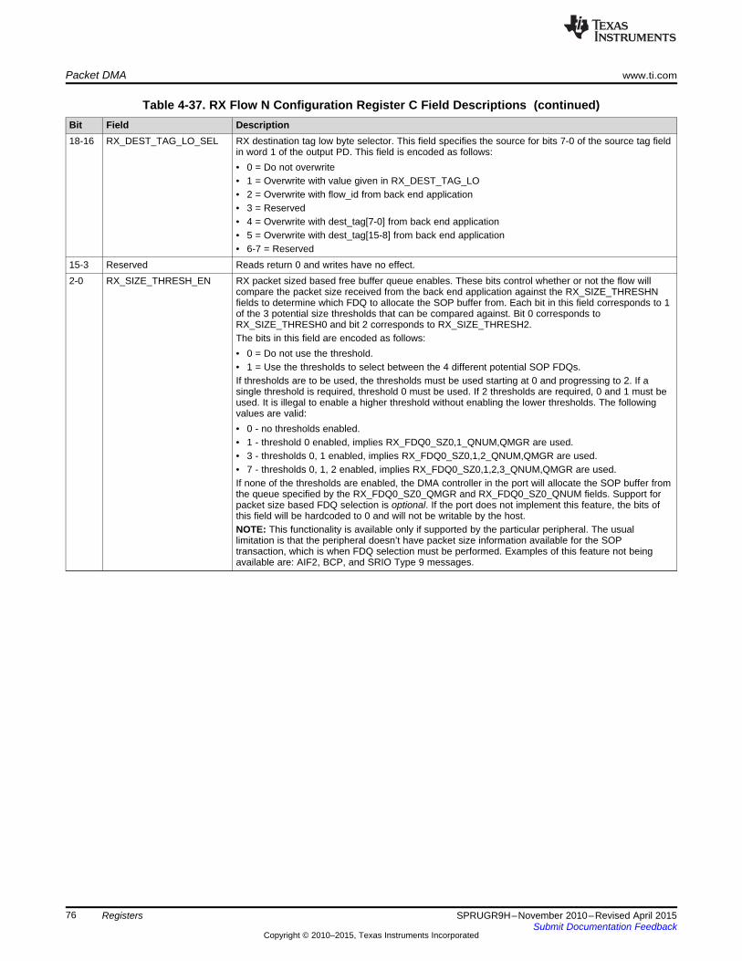
Packet DMA www.ti.com
Table 4-37. RX Flow N Configuration Register C Field Descriptions (continued)Bit Field Description18-16 RX_DEST_TAG_LO_SEL RX destination tag low byte selector. This field specifies the source for bits 7-0 of the source tag field
in word 1 of the output PD. This field is encoded as follows:• 0 = Do not overwrite• 1 = Overwrite with value given in RX_DEST_TAG_LO• 2 = Overwrite with flow_id from back end application• 3 = Reserved• 4 = Overwrite with dest_tag[7-0] from back end application• 5 = Overwrite with dest_tag[15-8] from back end application• 6-7 = Reserved
15-3 Reserved Reads return 0 and writes have no effect.2-0 RX_SIZE_THRESH_EN RX packet sized based free buffer queue enables. These bits control whether or not the flow will
compare the packet size received from the back end application against the RX_SIZE_THRESHNfields to determine which FDQ to allocate the SOP buffer from. Each bit in this field corresponds to 1of the 3 potential size thresholds that can be compared against. Bit 0 corresponds toRX_SIZE_THRESH0 and bit 2 corresponds to RX_SIZE_THRESH2.The bits in this field are encoded as follows:• 0 = Do not use the threshold.• 1 = Use the thresholds to select between the 4 different potential SOP FDQs.If thresholds are to be used, the thresholds must be used starting at 0 and progressing to 2. If asingle threshold is required, threshold 0 must be used. If 2 thresholds are required, 0 and 1 must beused. It is illegal to enable a higher threshold without enabling the lower thresholds. The followingvalues are valid:• 0 - no thresholds enabled.• 1 - threshold 0 enabled, implies RX_FDQ0_SZ0,1_QNUM,QMGR are used.• 3 - thresholds 0, 1 enabled, implies RX_FDQ0_SZ0,1,2_QNUM,QMGR are used.• 7 - thresholds 0, 1, 2 enabled, implies RX_FDQ0_SZ0,1,2,3_QNUM,QMGR are used.If none of the thresholds are enabled, the DMA controller in the port will allocate the SOP buffer fromthe queue specified by the RX_FDQ0_SZ0_QMGR and RX_FDQ0_SZ0_QNUM fields. Support forpacket size based FDQ selection is optional. If the port does not implement this feature, the bits ofthis field will be hardcoded to 0 and will not be writable by the host.NOTE: This functionality is available only if supported by the particular peripheral. The usuallimitation is that the peripheral doesn’t have packet size information available for the SOPtransaction, which is when FDQ selection must be performed. Examples of this feature not beingavailable are: AIF2, BCP, and SRIO Type 9 messages.
76 Registers SPRUGR9H–November 2010–Revised April 2015Submit Documentation Feedback
Copyright © 2010–2015, Texas Instruments Incorporated

www.ti.com Packet DMA
4.2.4.4 RX Flow N Configuration Register D (0x00C + 32×N)The RX Flow N Configuration Register D contains static configuration information for the RX DMA flow.The fields in this register can be safely changed only when all of the DMA channels that use this flow havebeen disabled. The fields in this register are shown in Figure 4-30:
Figure 4-30. RX Flow N Configuration Register D (0x00C + 32×N)31 30 29 28 27 16 15 14 13 12 11 0Reserved RX_FDQ0_SZ0_QMGR RX_FDQ0_SZ0_QNUM Reserved RX_FDQ1_QMGR RX_FDQ1_QNUM
R-0 W-0 W-0 R-0 W-0 W-0Legend: R = Read only; W = Write only; - n = value after reset
Table 4-38. RX Flow N Configuration Register D Field Descriptions
Bit Field Description31-30 Reserved Reads return 0 and writes have no effect.29-28 RX_FDQ0_SZ0_QMGR RX free descriptor 0 queue manager index – size 0. This field specifies which queue manager should
be used for the first RX buffer in a packet whose size is less than or equal to the rx_size0 value. Whenthe size thresholds are not enabled, this is the queue manager for the first RX buffer.
27-16 RX_FDQ0_SZ0_QNUM RX free descriptor 0 queue index – size 0. This field specifies which free descriptor queue should beused for the 1st RX buffer in a packet whose size is less than or equal to the rx_size0 value. When thesize thresholds are not enabled, this is the queue number for the first RX buffer.
15-14 Reserved Reads return 0 and writes have no effect.13-12 RX_FDQ1_QMGR RX free descriptor 1 queue manager index. This field specifies which queue manager should be used
for the 2nd RX buffer in a host type packet11-0 RX_FDQ1_QNUM RX free descriptor 1 queue index. This field specifies which free descriptor queue should be used for
the 2nd RX buffer in a host type packet
77SPRUGR9H–November 2010–Revised April 2015 RegistersSubmit Documentation Feedback
Copyright © 2010–2015, Texas Instruments Incorporated

Packet DMA www.ti.com
4.2.4.5 RX Flow N Configuration Register E (0x010 + 32×N)The RX Flow N Configuration Register E contains static configuration information for the RX DMA flow.The fields in this register can be safely changed only when all of the DMA channels that use this flow havebeen disabled. The fields in this register are shown in Figure 4-31:
Figure 4-31. RX Flow N Configuration Register E (0x010 + 32×N)31 30 29 28 27 16 15 14 13 12 11 0Reserved RX_FDQ2_QMGR RX_FDQ2_QNUM Reserved RX_FDQ3_QMGR RX_FDQ3_QNUM
R-0 W-0 W-0 R-0 W-0 W-0Legend: R = Read only; W = Write only; - n = value after reset
Table 4-39. RX Flow N Configuration Register E Field Descriptions
Bit Field Description31-30 Reserved Reads return 0 and writes have no effect.29-28 RX_FDQ2_QMGR RX free descriptor 2 queue manager index. This field specifies which queue manager should be used for the
3rd RX buffer in a host type packet27-16 RX_FDQ2_QNUM RX free descriptor 2 queue index. This field specifies which free descriptor queue should be used for the 3rd
RX buffer in a host type packet15-14 Reserved Reads return 0 and writes have no effect.13-12 RX_FDQ3_QMGR RX free descriptor 3 queue manager index. This field specifies which queue manager should be used for the
4th or later RX buffers in a host type packet11-0 RX_FDQ3_QNUM RX free descriptor 3 queue index. This field specifies which free descriptor queue should be used for the 4th
or later RX buffers in a host type packet
78 Registers SPRUGR9H–November 2010–Revised April 2015Submit Documentation Feedback
Copyright © 2010–2015, Texas Instruments Incorporated

www.ti.com Packet DMA
4.2.4.6 RX Flow N Configuration Register F (0x014 + 32×N)The RX Flow N Configuration Register F contains static configuration information for the RX DMA flow.The fields in this register can be safely changed only when all of the DMA channels that use this flow havebeen disabled. This register is optional. The fields in this register are shown in Figure 4-32:
Figure 4-32. RX Flow N Configuration Register F (0x014 + 32×N)31 16 15 0
RX_SIZE_THRESH0 RX_SIZE_THRESH1W-0 W-0
Legend: W = Write only; - n = value after reset
Table 4-40. RX Flow N Configuration Register F Field Descriptions
Bit Field Description31- RX_SIZE_THRESH0 RX packet size threshold 0. This value is left-shifted by 5 bits and compared against the packet size16 to determine which free descriptor queue should be used for the SOP buffer in the packet. If the
packet size is less than or equal to the value given in this threshold, the DMA controller in the portwill allocate the SOP buffer from the queue given by the RX_FDQ0_SZ0_QMGR andRX_FDQ0_SZ0_QNUM fields.This field is optional.
15-0 RX_SIZE_THRESH1 RX packet size threshold 1. This value is left-shifted by 5 bits and compared against the packet sizeto determine which free descriptor queue should be used for the SOP buffer in the packet. If thepacket size is greater than the RX_SIZE_THRESH0 but is less than or equal to the value given inthis threshold, the DMA controller in the port will allocate the SOP buffer from the queue given by theRX_FDQ0_SZ1_QMGR and RX_FDQ0_SZ1_QNUM fields. If enabled, this value must be greaterthan the value given in the RX_SIZE_THRESH0 field.This field is optional.
79SPRUGR9H–November 2010–Revised April 2015 RegistersSubmit Documentation Feedback
Copyright © 2010–2015, Texas Instruments Incorporated
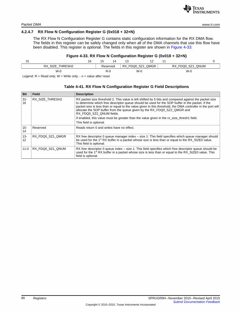
Packet DMA www.ti.com
4.2.4.7 RX Flow N Configuration Register G (0x018 + 32×N)The RX Flow N Configuration Register G contains static configuration information for the RX DMA flow.The fields in this register can be safely changed only when all of the DMA channels that use this flow havebeen disabled. This register is optional. The fields in this register are shown in Figure 4-33:
Figure 4-33. RX Flow N Configuration Register G (0x018 + 32×N)31 16 15 14 13 12 11 0
RX_SIZE_THRESH2 Reserved RX_FDQ0_SZ1_QMGR RX_FDQ0_SZ1_QNUMW-0 R-0 W-0 W-0
Legend: R = Read only; W = Write only; - n = value after reset
Table 4-41. RX Flow N Configuration Register G Field Descriptions
Bit Field Description31- RX_SIZE_THRESH2 RX packet size threshold 2. This value is left shifted by 5 bits and compared against the packet size16 to determine which free descriptor queue should be used for the SOP buffer in the packet. If the
packet size is less than or equal to the value given in this threshold, the DMA controller in the port willallocate the SOP buffer from the queue given by the RX_FDQ0_SZ2_QMGR andRX_FDQ0_SZ2_QNUM fields.If enabled, this value must be greater than the value given in the rx_size_thresh1 field.This field is optional.
15- Reserved Reads return 0 and writes have no effect.1413- RX_FDQ0_SZ1_QMGR RX free descriptor 0 queue manager index – size 1: This field specifies which queue manager should12 be used for the 1st RX buffer in a packet whose size is less than or equal to the RX_SIZE0 value.
This field is optional.11-0 RX_FDQ0_SZ1_QNUM RX free descriptor 0 queue index – size 1: This field specifies which free descriptor queue should be
used for the 1st RX buffer in a packet whose size is less than or equal to the RX_SIZE0 value. Thisfield is optional.
80 Registers SPRUGR9H–November 2010–Revised April 2015Submit Documentation Feedback
Copyright © 2010–2015, Texas Instruments Incorporated

www.ti.com Packet DMA
4.2.4.8 RX Flow N Configuration Register H (0x01C + 32×N)The RX Flow N Configuration Register H contains static configuration information for the RX DMA flow.The fields in this register can be safely changed only when all of the DMA channels that use this flow havebeen disabled. This register is optional. The fields in this register are shown in Figure 4-34:
Figure 4-34. RX Flow N Configuration Register H (0x01C + 32×N)31 30 29 28 27 16 15 14 13 12 11 0Reserved RX_FDQ0_SZ2_QMGR RX_FDQ0_SZ2_QNUM Reserved RX_FDQ0_SZ3_QMGR RX_FDQ0_SZ3_QNUM
R-0 W-0 W-0 R-0 W-0 W-0Legend: R = Read only; W = Write only; - n = value after reset
Table 4-42. RX Flow N Configuration Register H Field Descriptions
Bit Field Description31-30 Reserved Reads return 0 and writes have no effect.29-28 RX_FDQ0_SZ2_QMGR RX free descriptor 0 queue manager index – size 2. This field specifies which queue manager should be
used for the first RX buffer in a packet whose size is less than or equal to the rx_size2 value. This fieldis optional.
27-16 RX_FDQ0_SZ2_QNUM RX Free descriptor 0 queue index – size 2. This field specifies which Free Descriptor Queue should beused for the first RX buffer in a packet whose size is less than or equal to the rx_size2 value. This fieldis optional.
15-14 Reserved Reads return 0 and writes have no effect.13-12 RX_FDQ0_SZ3_QMGR RX free descriptor 0 queue manager index – size 3. This field specifies which queue manager should be
used for the first RX buffer in a packet whose size was not less than or equal to the rx_size3 value. Thisfield is optional. This queue manager is selected if the packet length does not match any enabled sizethreshold.
11-0 RX_FDQ0_SZ3_QNUM RX free descriptor 0 queue index – size 3. This field specifies which free descriptor queue should beused for the first RX buffer in a packet whose size is less than or equal to the rx_size3 value. This fieldis optional. This queue number is selected if the packet length does not match any enabled sizethreshold.
81SPRUGR9H–November 2010–Revised April 2015 RegistersSubmit Documentation Feedback
Copyright © 2010–2015, Texas Instruments Incorporated
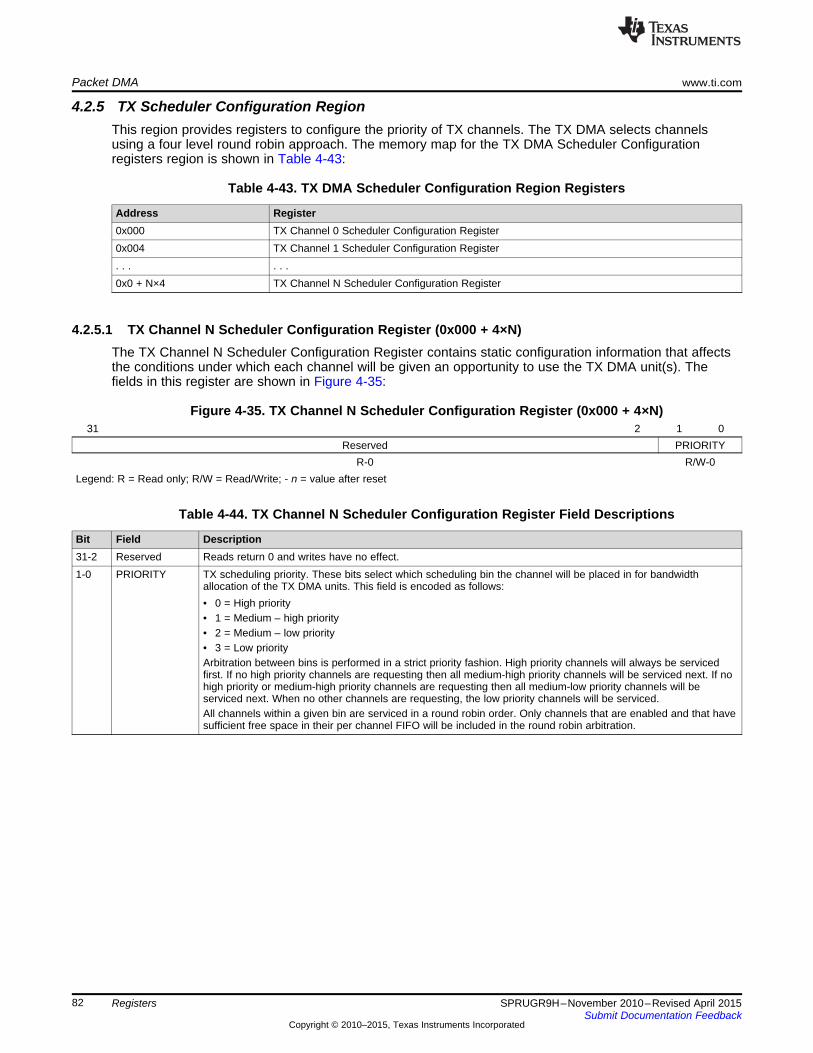
Packet DMA www.ti.com
4.2.5 TX Scheduler Configuration RegionThis region provides registers to configure the priority of TX channels. The TX DMA selects channelsusing a four level round robin approach. The memory map for the TX DMA Scheduler Configurationregisters region is shown in Table 4-43:
Table 4-43. TX DMA Scheduler Configuration Region Registers
Address Register0x000 TX Channel 0 Scheduler Configuration Register0x004 TX Channel 1 Scheduler Configuration Register. . . . . .0x0 + N×4 TX Channel N Scheduler Configuration Register
4.2.5.1 TX Channel N Scheduler Configuration Register (0x000 + 4×N)The TX Channel N Scheduler Configuration Register contains static configuration information that affectsthe conditions under which each channel will be given an opportunity to use the TX DMA unit(s). Thefields in this register are shown in Figure 4-35:
Figure 4-35. TX Channel N Scheduler Configuration Register (0x000 + 4×N)31 2 1 0
Reserved PRIORITYR-0 R/W-0
Legend: R = Read only; R/W = Read/Write; - n = value after reset
Table 4-44. TX Channel N Scheduler Configuration Register Field Descriptions
Bit Field Description31-2 Reserved Reads return 0 and writes have no effect.1-0 PRIORITY TX scheduling priority. These bits select which scheduling bin the channel will be placed in for bandwidth
allocation of the TX DMA units. This field is encoded as follows:• 0 = High priority• 1 = Medium – high priority• 2 = Medium – low priority• 3 = Low priorityArbitration between bins is performed in a strict priority fashion. High priority channels will always be servicedfirst. If no high priority channels are requesting then all medium-high priority channels will be serviced next. If nohigh priority or medium-high priority channels are requesting then all medium-low priority channels will beserviced next. When no other channels are requesting, the low priority channels will be serviced.All channels within a given bin are serviced in a round robin order. Only channels that are enabled and that havesufficient free space in their per channel FIFO will be included in the round robin arbitration.
82 Registers SPRUGR9H–November 2010–Revised April 2015Submit Documentation Feedback
Copyright © 2010–2015, Texas Instruments Incorporated

www.ti.com QMSS PDSPs
4.3 QMSS PDSPsThe queue manager sub system contains two or eight packed data structure processors (PDSP) andassociated hardware that allow autonomous QMSS-related tasks with interrupt notification. PDSPs arenormally loaded with firmware during configuration, then programmed with firmware-specific commands.Because the interrupt distributors service pairs of PDSPs, most firmware images can be loaded on evenor odd PDSPs, with restrictions usually due to conflicts with interrupt usage. For example, using Acc48 onPDSP1 and PDSP5 would cause both instances to drive the same interrupts on INTD1. If Acc48 is loadedon PDSP1, it can also be loaded on PDSP3 or PDSP7.
The firmware builds provided in the PDK come in several varieties in both big- and little-endian formats.Three types of firmware are provided:• Descriptor accumulator firmware that monitors programmed queues, pops descriptors found there and
interrupts the host with a list of descriptor addresses (this firmware comes in 16, 32, and 48 channelbuilds)
• Quality of service firmware that monitors all packet flows in the system, and verifies that neither theperipherals nor the host CPU are overwhelmed with packets
• Open Event Manager firmware that provides dynamic load balancing of CorePacs.
Table 4-45 shows which PDSP may be used for each firmware type, though several combinations will notwork due to conflicts. Table 4-46 lists several configurations that avoid conflicts.
Table 4-45. Possible PDSP Firmware Loading
PDSP 1 PDSP 2 PDSP 3 PDSP 4 PDSP 5 PDSP 6 PDSP 7 PDSP 8INTD 1 INTD 2 INTD 1 INTD 2
Acc 48 Acc 48 Acc 48 Acc 48QoS QoS QoS QoS
Acc 32 Acc 32 Acc 32 Acc 32Acc 16 Acc 16 Acc 16 Acc 16
OEM1 OEM2 OEM1 OEM2 OEM1 OEM2 OEM1 OEM2
Table 4-46. Recommended PDSP Firmware Loading
PDSP 1 PDSP 2 PDSP 3 PDSP 4 PDSP 5 PDSP 6 PDSP 7 PDSP 8INTD 1 INTD 2 INTD 1 INTD 2
Acc 48 Acc 48 OEM1 QoS OEM1 QoSAcc 48 QoS Acc 48 OEM1 QoSAcc 48 QoS Acc 32 Acc 16 OEM1 OEM2 OEM1 OEM2Acc 48 QoS OEM1 OEM2 OEM1 OEM2 OEM1 OEM2Acc 32 Acc 16 Acc 32 Acc 16 OEM1 QoS OEM1 QoSAcc 32 Acc 16 Acc 32 Acc 16 OEM1 QoSAcc 32 Acc 16 Acc 32 Acc 16 OEM1 OEM2 OEM1 OEM2Acc 32 Acc 16 OEM1 OEM2 OEM1 OEM2 OEM1 OEM2OEM1 OEM2 OEM1 OEM2 OEM1 OEM2 OEM1 OEM2
83SPRUGR9H–November 2010–Revised April 2015 RegistersSubmit Documentation Feedback
Copyright © 2010–2015, Texas Instruments Incorporated

QMSS PDSPs www.ti.com
4.3.1 Descriptor Accumulation FirmwareFor accumulation purposes, the firmware will read the queue status RAM to obtain status information onthe programmed queues. So the host software must program the Queue N Status and ConfigurationRegister D registers with the value 0x81 for every queue that is to be examined by the firmware. This willcause the status bit in the queue status RAM to be set while the queue is not empty, and clear whenempty.
The 32-channel version provides 32 high channels - i.e. channels 0 to 31 that are serviced once periteration through the channels. The 16-channel firmware provides 16 channels (0...15) that are alsoscanned as fast as possible (e.g. high), yet these trigger the low priority interrupts. In this way, the 16- and32-channel accumulators may be used together without interrupt interference. The 48-channel versionprovides channels 0 to 31 that are high, and channels 32 to 47 that are low — serviced one at a timethrough each iteration through channels 0 to 31. Note that any channel in any version of the firmware maybe configured to monitor 32 contiguous queues, not just the low priority channels.
The accumulator is programmed using a 20-byte shared memory command buffer. The command bufferconsists of a command word, followed by several parameters. The process of writing a command is tocheck to see if the command buffer is free, then write the command parameters, and finally write thecommand. Optionally, the calling program can wait for command completion.
The command buffer is free when the command field is set to 0x00.
When a command is written, the host CPU must write the word containing the command byte last. Thecommand byte is written with bit 7 set to signify a command to the PDSP. The command buffer is ininternal RAM and should not be marked as cacheable by the host CPU. If the RAM is cached on the hostCPU, then the host must perform two separate writes and cache flushes; the first for writing theparameters, and then a second independent write and cache flush for writing the command word. Allwrites should be performed as 32 bit quantities.
Once the command is written, the PDSP will clear the command field upon command completion. Thecommand results can then be read from the return code field. Note that the PDSP must be enabled beforethe firmware can be programmed.
4.3.1.1 Command Buffer InterfaceThe single queue channels are high priority channels that monitor a single queue. The format of thecommand is shown in Table 4-47:
Table 4-47. Command Buffer Format
FieldCommand BufferOffset Byte 3 Byte 2 Byte 1 Byte 00x00 Return code 0 Command Channel (0-47)0x04 Queue enable mask0x08 List buffer physical address0x0C Max page entries Queue number0x10 0 Configuration Timer load count
84 Registers SPRUGR9H–November 2010–Revised April 2015Submit Documentation Feedback
Copyright © 2010–2015, Texas Instruments Incorporated
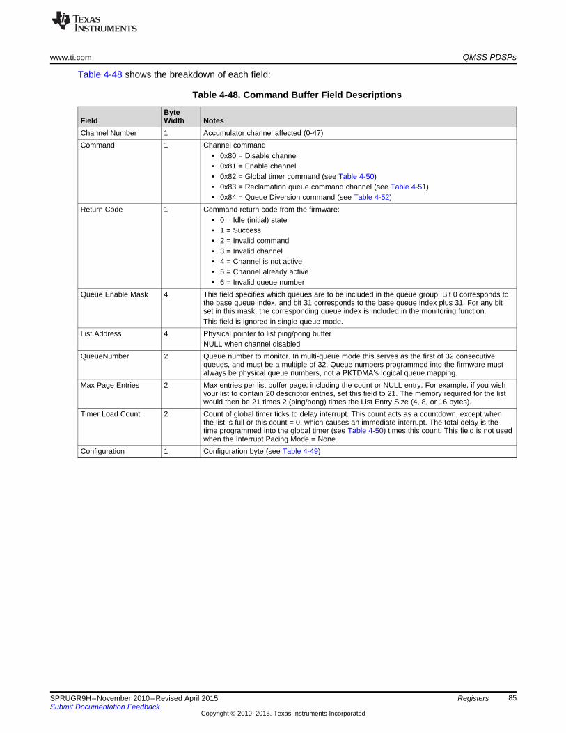
www.ti.com QMSS PDSPs
Table 4-48 shows the breakdown of each field:
Table 4-48. Command Buffer Field Descriptions
ByteField Width NotesChannel Number 1 Accumulator channel affected (0-47)Command 1 Channel command
• 0x80 = Disable channel• 0x81 = Enable channel• 0x82 = Global timer command (see Table 4-50)• 0x83 = Reclamation queue command channel (see Table 4-51)• 0x84 = Queue Diversion command (see Table 4-52)
Return Code 1 Command return code from the firmware:• 0 = Idle (initial) state• 1 = Success• 2 = Invalid command• 3 = Invalid channel• 4 = Channel is not active• 5 = Channel already active• 6 = Invalid queue number
Queue Enable Mask 4 This field specifies which queues are to be included in the queue group. Bit 0 corresponds tothe base queue index, and bit 31 corresponds to the base queue index plus 31. For any bitset in this mask, the corresponding queue index is included in the monitoring function.This field is ignored in single-queue mode.
List Address 4 Physical pointer to list ping/pong bufferNULL when channel disabled
QueueNumber 2 Queue number to monitor. In multi-queue mode this serves as the first of 32 consecutivequeues, and must be a multiple of 32. Queue numbers programmed into the firmware mustalways be physical queue numbers, not a PKTDMA’s logical queue mapping.
Max Page Entries 2 Max entries per list buffer page, including the count or NULL entry. For example, if you wishyour list to contain 20 descriptor entries, set this field to 21. The memory required for the listwould then be 21 times 2 (ping/pong) times the List Entry Size (4, 8, or 16 bytes).
Timer Load Count 2 Count of global timer ticks to delay interrupt. This count acts as a countdown, except whenthe list is full or this count = 0, which causes an immediate interrupt. The total delay is thetime programmed into the global timer (see Table 4-50) times this count. This field is not usedwhen the Interrupt Pacing Mode = None.
Configuration 1 Configuration byte (see Table 4-49)
85SPRUGR9H–November 2010–Revised April 2015 RegistersSubmit Documentation Feedback
Copyright © 2010–2015, Texas Instruments Incorporated

QMSS PDSPs www.ti.com
The configuration byte contains several sub-fields as detailed in Table 4-49:
Table 4-49. Configuration Byte Subfields
Bits Field Name Notes7-6 Reserved Reads return 0 and writes have no effect.5 Multi-Queue Mode • 0 = Single queue mode — the channel monitors a single queue.
• 1 = Multi-queue mode — the channel monitors up to 32 queues starting at the supplied base queueindex.
4 List Count Mode • 0 = NULL terminate mode — the last list entry is used to store a NULL pointer record (NULL terminator)to mark the end of list.
• 1 = Entry count mode — the first list entry is used to store the total list entry count (not including thelength entry).
3-2 List Entry Size • 0 = D register only (4 byte entries)• 1 = C, D registers (8 byte entries)• 2 = A, B, C, D registers (16 byte entries)Note: For Lo-Priority, when register C is extracted, the firmware will OR the index of the queue number intothe upper 16 bits. This is so the original queue can be identified. Example: If the base queue number is 32,a value of 0 (in the upper 16 bits) equals queue 32, 1 = 33, ... 31 = 63.
1-0 Interrupt Pacing Mode • 0 = None — interrupt on entry threshold count only (i.e. list full)• 1 = Time delay since last interrupt. This produces a periodic interrupt (as long as the list does not fill
early and descriptors continue arriving).• 2 = Time delay since first new packet. This starts the timer countdown with the first packet received
following a previous interrupt.• 3 = Time delay since last new packet. This restarts the timer countdown with each new packet.Note: When using a Lo-Priority channel in the 48 channel Accumulator, the channel (including the TimerLoad Count) are serviced at 1/16 the rate of the High Priority channels, and the Lo-Priority channels in the16 channel Accumulator. If not accounted for (i.e. reducing the Timer Load Count), the overall delay will be~16x larger than expected.
4.3.1.2 Global Timer Command InterfaceThe global timer value used by the PDSP may be programmed using the format shown in Table 4-50. Thistimer has a programmable count based on the sub-system clock. When this count expires, a local tick isregistered in the firmware. The tick is used when timing channel interrupts based on the Timer Load Countvalue supplied in the channel configuration.
Table 4-50. Global Timer Command Format
FieldCommand BufferOffset Byte 3 Byte 2 Byte 1 Byte 00x00 Return code 0 0x82 00x04 0 Timer Constant
The value of Timer Constant is the number of queue manager sub-system clocks divided by 2 thatcomprise a single tick in the accumulator firmware.
For example, if the sub-system clock is 350 MHz (the default), and the desired firmware tick is 20 µs, theproper timer constant for this command is calculated as follows:
Timer constant = (350,000,000 cycles/sec) × (0.000020 sec) / (2 cycles) = 3,500
The firmware initializes with a default timer constant value of 4375 (25 µs at 350Mhz) For devices withother sub-system clock rates, the default timer value will not be correct (at 400Mhz, 25 µs = (400,000,000× 0.000025) / 2 = 5,000).
86 Registers SPRUGR9H–November 2010–Revised April 2015Submit Documentation Feedback
Copyright © 2010–2015, Texas Instruments Incorporated
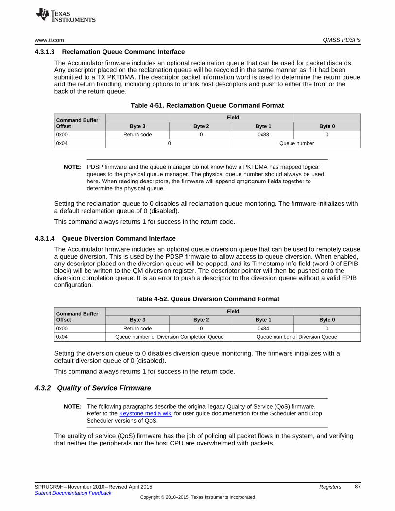
www.ti.com QMSS PDSPs
4.3.1.3 Reclamation Queue Command InterfaceThe Accumulator firmware includes an optional reclamation queue that can be used for packet discards.Any descriptor placed on the reclamation queue will be recycled in the same manner as if it had beensubmitted to a TX PKTDMA. The descriptor packet information word is used to determine the return queueand the return handling, including options to unlink host descriptors and push to either the front or theback of the return queue.
Table 4-51. Reclamation Queue Command Format
FieldCommand BufferOffset Byte 3 Byte 2 Byte 1 Byte 00x00 Return code 0 0x83 00x04 0 Queue number
NOTE: PDSP firmware and the queue manager do not know how a PKTDMA has mapped logicalqueues to the physical queue manager. The physical queue number should always be usedhere. When reading descriptors, the firmware will append qmgr:qnum fields together todetermine the physical queue.
Setting the reclamation queue to 0 disables all reclamation queue monitoring. The firmware initializes witha default reclamation queue of 0 (disabled).
This command always returns 1 for success in the return code.
4.3.1.4 Queue Diversion Command InterfaceThe Accumulator firmware includes an optional queue diversion queue that can be used to remotely causea queue diversion. This is used by the PDSP firmware to allow access to queue diversion. When enabled,any descriptor placed on the diversion queue will be popped, and its Timestamp Info field (word 0 of EPIBblock) will be written to the QM diversion register. The descriptor pointer will then be pushed onto thediversion completion queue. It is an error to push a descriptor to the diversion queue without a valid EPIBconfiguration.
Table 4-52. Queue Diversion Command Format
FieldCommand BufferOffset Byte 3 Byte 2 Byte 1 Byte 00x00 Return code 0 0x84 00x04 Queue number of Diversion Completion Queue Queue number of Diversion Queue
Setting the diversion queue to 0 disables diversion queue monitoring. The firmware initializes with adefault diversion queue of 0 (disabled).
This command always returns 1 for success in the return code.
4.3.2 Quality of Service Firmware
NOTE: The following paragraphs describe the original legacy Quality of Service (QoS) firmware.Refer to the Keystone media wiki for user guide documentation for the Scheduler and DropScheduler versions of QoS.
The quality of service (QoS) firmware has the job of policing all packet flows in the system, and verifyingthat neither the peripherals nor the host CPU are overwhelmed with packets.
87SPRUGR9H–November 2010–Revised April 2015 RegistersSubmit Documentation Feedback
Copyright © 2010–2015, Texas Instruments Incorporated
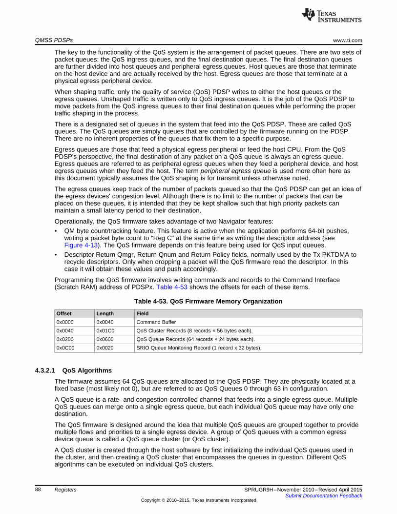
QMSS PDSPs www.ti.com
The key to the functionality of the QoS system is the arrangement of packet queues. There are two sets ofpacket queues: the QoS ingress queues, and the final destination queues. The final destination queuesare further divided into host queues and peripheral egress queues. Host queues are those that terminateon the host device and are actually received by the host. Egress queues are those that terminate at aphysical egress peripheral device.
When shaping traffic, only the quality of service (QoS) PDSP writes to either the host queues or theegress queues. Unshaped traffic is written only to QoS ingress queues. It is the job of the QoS PDSP tomove packets from the QoS ingress queues to their final destination queues while performing the propertraffic shaping in the process.
There is a designated set of queues in the system that feed into the QoS PDSP. These are called QoSqueues. The QoS queues are simply queues that are controlled by the firmware running on the PDSP.There are no inherent properties of the queues that fix them to a specific purpose.
Egress queues are those that feed a physical egress peripheral or feed the host CPU. From the QoSPDSP's perspective, the final destination of any packet on a QoS queue is always an egress queue.Egress queues are referred to as peripheral egress queues when they feed a peripheral device, and hostegress queues when they feed the host. The term peripheral egress queue is used more often here asthis document typically assumes the QoS shaping is for transmit unless otherwise noted.
The egress queues keep track of the number of packets queued so that the QoS PDSP can get an idea ofthe egress devices' congestion level. Although there is no limit to the number of packets that can beplaced on these queues, it is intended that they be kept shallow such that high priority packets canmaintain a small latency period to their destination.
Operationally, the QoS firmware takes advantage of two Navigator features:• QM byte count/tracking feature. This feature is active when the application performs 64-bit pushes,
writing a packet byte count to “Reg C” at the same time as writing the descriptor address (seeFigure 4-13). The QoS firmware depends on this feature being used for QoS input queues.
• Descriptor Return Qmgr, Return Qnum and Return Policy fields, normally used by the Tx PKTDMA torecycle descriptors. Only when dropping a packet will the QoS firmware read the descriptor. In thiscase it will obtain these values and push accordingly.
Programming the QoS firmware involves writing commands and records to the Command Interface(Scratch RAM) address of PDSPx. Table 4-53 shows the offsets for each of these items.
Table 4-53. QoS Firmware Memory Organization
Offset Length Field0x0000 0x0040 Command Buffer0x0040 0x01C0 QoS Cluster Records (8 records × 56 bytes each).0x0200 0x0600 QoS Queue Records (64 records × 24 bytes each).0x0C00 0x0020 SRIO Queue Monitoring Record (1 record x 32 bytes).
4.3.2.1 QoS AlgorithmsThe firmware assumes 64 QoS queues are allocated to the QoS PDSP. They are physically located at afixed base (most likely not 0), but are referred to as QoS Queues 0 through 63 in configuration.
A QoS queue is a rate- and congestion-controlled channel that feeds into a single egress queue. MultipleQoS queues can merge onto a single egress queue, but each individual QoS queue may have only onedestination.
The QoS firmware is designed around the idea that multiple QoS queues are grouped together to providemultiple flows and priorities to a single egress device. A group of QoS queues with a common egressdevice queue is called a QoS queue cluster (or QoS cluster).
A QoS cluster is created through the host software by first initializing the individual QoS queues used inthe cluster, and then creating a QoS cluster that encompasses the queues in question. Different QoSalgorithms can be executed on individual QoS clusters.
88 Registers SPRUGR9H–November 2010–Revised April 2015Submit Documentation Feedback
Copyright © 2010–2015, Texas Instruments Incorporated
www.ti.com QMSS PDSPs
4.3.2.1.1 Modified Token Bucket AlgorithmBasic OperationThe modified token bucket algorithm allows each queue in a cluster to be assigned a fixed rate in bytesper time iteration (typically 25 µs, but is configurable). This is called iteration credit. In addition, there is amaximum number of bytes that can be retained as credit against a future traffic burst. This retained creditis called total credit. The maximum limit is called maximum credit.
Iteration credit is added to a queue's total credit at the start of each sampling period. While total creditremains above 0, the packet waiting at the head of the QoS queue is examined for size. If the byte size ofthe packet is less than or equal to the queue's total credit, the packet is forwarded and the packet bytesize is deducted from the credit bytes. The queue's unused credit is carried over to the next iteration (heldin its total credit), up to the maximum amount allocated to the queue.
For example, if a flow is rated for 40Mb/s, but can burst up to 20,000 bytes at a time, the queue would beconfigured as follows on a system with a 25-µs iteration:• Iteration Credit = 125 bytes (40 Mb/s is 125 bytes every 25 µs)• Maximum Credit = 20,000 bytes
The sum total of iteration credit for all queues in the cluster should add up to the total expected data rateof the egress device. When configuring a cluster, it is important that this rule be followed.
Global Credit and BorrowingAfter all packets have been transmitted from a QoS queue, the queue's remaining total credit can notexceed the maximum credit allocated to that queue. Any credit bytes above the maximum credit limit areadded to a global credit sum, and the total credit is set to the maximum credit.
Any queue may borrow from the global credit pool when doing so allows the queue to transmit anadditional packet or is used to fill its allotted maximum credit level. This is done on a first come, firstserved basis. The global credit system allows queues that are allocated less credit than necessary tosaturate a device to make use of the additional bandwidth when it is not being used by the other QoSqueues in the cluster.
Thus in the example above, the queue was set to 40 Mb/s can use the entire bandwidth of the egressdevice when the other cluster queues are idle.
There is also a configurable maximum size on global credit. The limit on global credit is checked afterevery queue is processed. So for example, if the maximum global credit were set to 0, then the creditborrowing feature would be disabled.
Congestion and Packet DiscardA queue can become congested if the bandwidth of data arriving exceeds the bandwidth allocated oravailable. Each queue has a drop threshold expressed in bytes. Once the backlog in a QoS queuereaches its drop threshold, any packets that can not be transmitted are discarded until the backlog iscleared back below the threshold level.
For example, the 40-Mb/s flow with the 20,000-byte burst could be assumed to be congested if more thanone burst’s worth of data has accumulated on the QoS queue. In this case, the drop threshold would beset to 40,000 bytes.
Congestion and Credit ScalingThe destination queue for a QoS cluster may also be congested. For example, a cluster may configure100-Mb/s worth of data on an Ethernet device, but find that, for various reasons, the device is capable ofsending only 70 Mb/s. The cluster algorithm will automatically scale the credit assigned to each queueaccording to how congested the egress queue becomes.
Each QoS cluster is configured with four egress congestion threshold values. Iteration credit is assigned toeach queue in the cluster depending on the egress congestion, and the value of these four congestionthresholds. This is implemented as shown in Table 4-54.
89SPRUGR9H–November 2010–Revised April 2015 RegistersSubmit Documentation Feedback
Copyright © 2010–2015, Texas Instruments Incorporated

QMSS PDSPs www.ti.com
Table 4-54. Destination Congestion and Credit Scaling
Egress Queue Congestion (Backlog) Level QoS Queue Credit AssignedBacklog < Threshold 1 Double creditBacklog >= Threshold 1 and Backlog < Threshold 2 Normal creditBacklog >= Threshold 2 and Backlog < Threshold 3 Half creditBacklog >= Threshold 3 and Backlog < Threshold 4 Quarter creditBacklog >= Threshold 4 No credit
Note that the use of double credit for near idle situations is used to ensure that each queue's burstpotential be refilled as quickly as possible. It also allows the full bandwidth of a device to be used whenthe allocated bandwidth isn't quite enough to fill the device (for example allocating 98 Mb/s from a 100-Mb/s device).
If the egress queue for a cluster becomes congested due to external influences (like heavy load on thenetwork), the credit scaling will affect each QoS queue equally. There may be cases in which some flowsrequire hard real-time scheduling. In this case, the queue can be marked as real time and exempt fromcredit scaling.
For example, in a 100-Mb/s system that has two flows, a 40-Mb/s flow and everything else, the first queuein the cluster would be configured as 40-Mb/s real time, and the second queue can be configured as 60-Mb/s (without the real time setting). As the available bandwidth on the network drops, the 40-Mb/s flowwould remain unaffected, while the 60-Mb/s flow would be scaled down.
Fixed Priority ConfigurationThis algorithm can also be used to implement a fixed-priority method, in which each queue is serviced in afixed priority with the first queue in the cluster being the highest priority. This is done by assigning alliteration credit to the first queue in the cluster, and setting the maximum credit of each queue to themaximum packet size. This ensures that credit is passed only to subsequent queues when there are nopackets waiting on the current queue.
For example, assume there are three queues, A, B, and C. In a simple priority system, queue A wouldalways transmit packets when packets are available, while queue B transmits only when queue A is idle,and queue C transmits only when queue B is idle.
On a 100-Mb/s system, the queues could be configured as follows:• Queue A
– Iteration Credit = 313 (100 Mb/s is 312.5 bytes every 25 µs)– Max Credit = 1514
• Queue B– Iteration Credit = 0– Max Credit = 1514
• Queue C– Iteration Credit = 0– Max Credit = 1514
The way the algorithm works, queue A will get 313 bytes of credit at the start of each iteration. Becausequeue A can hold up to 1514 bytes as max credit, queue A will never pass credit onto queue B whilequeue A has a packet. (If queue A has more than 1514 bytes of credit, it can always forward a packet.)
Queue A must be idle for an entire packet time (1514 bytes of iteration credit) before any credit will startflowing into queue B. The same relationship holds between queue B and queue C. The only way queue Bsends a packet is after queue A is idle for a packet time, and the only way queue C can send a packet isafter queue B is idle for a packet time.
90 Registers SPRUGR9H–November 2010–Revised April 2015Submit Documentation Feedback
Copyright © 2010–2015, Texas Instruments Incorporated

www.ti.com QMSS PDSPs
4.3.2.2 Command Buffer InterfaceThe process of writing a command is to check to see if the command buffer is free, then write thecommand parameters, and finally write the command. Optionally, the caller can wait for commandcompletion.
The command buffer is free when the command field of the first work in the command buffer is set to0x00.
When a command is written, the host CPU must write the word containing the command byte last. Thecommand buffer is in internal RAM and should not be marked as cacheable by the host CPU. If the RAMis cached on the host CPU, then the host must perform two separate writes and cache flushes; the first forwriting the parameters, and then a second independent write and cache flush for writing the commandword. All writes should be performed as 32-bit quantities.
Note that the first word of the command buffer appears in a non-contiguous memory region as theremaining fields in the buffer.
After the command is written, the PDSP will clear the command field upon command completion. Thecommand results can then be read from the Return Code field.
The command buffer interface for the QoS firmware is shown in Table 4-55.
Table 4-55. Command Buffer Interface
FieldCommand BufferOffset Byte 3 Byte 2 Byte 1 Byte 00x00 Index Option Command0x04 Return Code
Table 4-56 shows the breakdown of each field.
Table 4-56. Command Buffer Field Descriptions
ByteField Width NotesIndex 2 Command Index (use varies with each firmware command)Option 1 Command Option (use varies with each firmware command)Command 1 QoS command:
• 0x80 = Get queue base• 0x81 = Set queue base• 0x82 = Global timer command (same as accumulation firmware; see Table 4-50)• 0x83 = Cluster enable• 0x84 = SRIO enable
Return Code 4 Used to return status to the caller:• QCMD_RETCODE_SUCCESS 0x01• QCMD_RETCODE_INVALID_COMMAND 0x02• QCMD_RETCODE_INVALID_INDEX 0x03• QCMD_RETCODE_INVALID_OPTION 0x04
91SPRUGR9H–November 2010–Revised April 2015 RegistersSubmit Documentation Feedback
Copyright © 2010–2015, Texas Instruments Incorporated
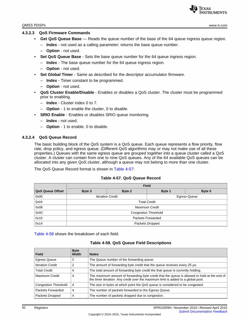
QMSS PDSPs www.ti.com
4.3.2.3 QoS Firmware Commands• Get QoS Queue Base — Reads the queue number of the base of the 64 queue ingress queue region.
– Index - not used as a calling parameter; returns the base queue number.– Option - not used.
• Set QoS Queue Base - Sets the base queue number for the 64 queue ingress region.– Index - The base queue number for the 64 queue ingress region.– Option - not used.
• Set Global Timer - Same as described for the descriptor accumulator firmware.– Index - Timer constant to be programmed.– Option - not used.
• QoS Cluster Enable/Disable - Enables or disables a QoS cluster. The cluster must be programmedprior to enabling.– Index - Cluster index 0 to 7.– Option - 1 to enable the cluster, 0 to disable.
• SRIO Enable - Enables or disables SRIO queue monitoring.– Index - not used.– Option - 1 to enable, 0 to disable.
4.3.2.4 QoS Queue RecordThe basic building block of the QoS system is a QoS queue. Each queue represents a flow priority, flowrate, drop policy, and egress queue. (Different QoS algorithms may or may not make use of all theseproperties.) Queues with the same egress queue are grouped together into a queue cluster called a QoScluster. A cluster can contain from one to nine QoS queues. Any of the 64 available QoS queues can beallocated into any given QoS cluster, although a queue may not belong to more than one cluster.
The QoS Queue Record format is shown in Table 4-57:
Table 4-57. QoS Queue Record
FieldQoS Queue Offset Byte 3 Byte 2 Byte 1 Byte 00x00 Iteration Credit Egress Queue0x04 Total Credit0x08 Maximum Credit0x0C Congestion Threshold0x10 Packets Forwarded0x14 Packets Dropped
Table 4-58 shows the breakdown of each field:
Table 4-58. QoS Queue Field Descriptions
ByteField Width NotesEgress Queue 2 The Queue number of the forwarding queue.Iteration Credit 2 The amount of forwarding byte credit that the queue receives every 25 µs.Total Credit 4 The total amount of forwarding byte credit the that queue is currently holding.Maximum Credit 4 The maximum amount of forwarding byte credit that the queue is allowed to hold at the end of
the timer iteration. Any credit over the maximum limit is added to a global pool.Congestion Threshold 4 The size in bytes at which point the QoS queue is considered to be congested.Packets Forwarded 4 The number of packets forwarded to the Egress Queue.Packets Dropped 4 The number of packets dropped due to congestion.
92 Registers SPRUGR9H–November 2010–Revised April 2015Submit Documentation Feedback
Copyright © 2010–2015, Texas Instruments Incorporated
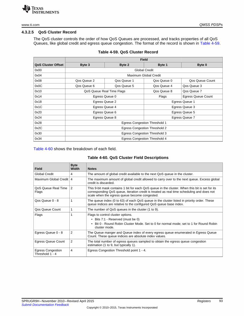
www.ti.com QMSS PDSPs
4.3.2.5 QoS Cluster RecordThe QoS cluster controls the order of how QoS Queues are processed, and tracks properties of all QoSQueues, like global credit and egress queue congestion. The format of the record is shown in Table 4-59.
Table 4-59. QoS Cluster Record
FieldQoS Cluster Offset Byte 3 Byte 2 Byte 1 Byte 00x00 Global Credit0x04 Maximum Global Credit0x08 Qos Queue 2 Qos Queue 1 Qos Queue 0 Qos Queue Count0x0C Qos Queue 6 Qos Queue 5 Qos Queue 4 Qos Queue 30x10 QoS Queue Real Time Flags Qos Queue 8 Qos Queue 70x14 Egress Queue 0 Flags Egress Queue Count0x18 Egress Queue 2 Egress Queue 10x1C Egress Queue 4 Egress Queue 30x20 Egress Queue 6 Egress Queue 50x24 Egress Queue 8 Egress Queue 70x28 Egress Congestion Threshold 10x2C Egress Congestion Threshold 20x30 Egress Congestion Threshold 30x34 Egress Congestion Threshold 4
Table 4-60 shows the breakdown of each field.
Table 4-60. QoS Cluster Field Descriptions
ByteField Width NotesGlobal Credit 4 The amount of global credit available to the next QoS queue in the cluster.Maximum Global Credit 4 The maximum amount of global credit allowed to carry over to the next queue. Excess global
credit is discarded.QoS Queue Real Time 2 This 9-bit mask contains 1 bit for each QoS queue in the cluster. When this bit is set for itsFlags corresponding QoS queue, iteration credit is treated as real time scheduling and does not
scale when the egress queue become congested.Qos Queue 0 - 8 1 The queue index (0 to 63) of each QoS queue in the cluster listed in priority order. These
queue indices are relative to the configured QoS queue base index.Qos Queue Count 1 The number of QoS queues in the cluster (1 to 9).Flags 1 Flags to control cluster options.
• Bits 7:1 - Reserved (must be 0)• Bit 0 - Round Robin Cluster Mode. Set to 0 for normal mode; set to 1 for Round Robin
cluster mode.Egress Queue 0 - 8 2 The Queue manger and Queue index of every egress queue enumerated in Egress Queue
Count. These queue indices are absolute index values.Egress Queue Count 2 The total number of egress queues sampled to obtain the egress queue congestion
estimation (1 to 9, but typically 1).Egress Congestion 4 Egress Congestion Threshold point 1 - 4.Threshold 1 - 4
93SPRUGR9H–November 2010–Revised April 2015 RegistersSubmit Documentation Feedback
Copyright © 2010–2015, Texas Instruments Incorporated
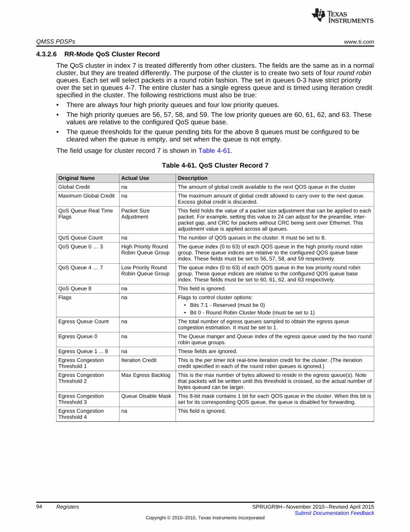
QMSS PDSPs www.ti.com
4.3.2.6 RR-Mode QoS Cluster RecordThe QoS cluster in index 7 is treated differently from other clusters. The fields are the same as in a normalcluster, but they are treated differently. The purpose of the cluster is to create two sets of four round robinqueues. Each set will select packets in a round robin fashion. The set in queues 0-3 have strict priorityover the set in queues 4-7. The entire cluster has a single egress queue and is timed using iteration creditspecified in the cluster. The following restrictions must also be true:• There are always four high priority queues and four low priority queues.• The high priority queues are 56, 57, 58, and 59. The low priority queues are 60, 61, 62, and 63. These
values are relative to the configured QoS queue base.• The queue thresholds for the queue pending bits for the above 8 queues must be configured to be
cleared when the queue is empty, and set when the queue is not empty.
The field usage for cluster record 7 is shown in Table 4-61.
Table 4-61. QoS Cluster Record 7
Original Name Actual Use DescriptionGlobal Credit na The amount of global credit available to the next QOS queue in the clusterMaximum Global Credit na The maximum amount of global credit allowed to carry over to the next queue.
Excess global credit is discarded.QoS Queue Real Time Packet Size This field holds the value of a packet size adjustment that can be applied to eachFlags Adjustment packet. For example, setting this value to 24 can adjust for the preamble, inter-
packet gap, and CRC for packets without CRC being sent over Ethernet. Thisadjustment value is applied across all queues.
QoS Queue Count na The number of QOS queues in the cluster. It must be set to 8.QoS Queue 0 … 3 High Priority Round The queue index (0 to 63) of each QOS queue in the high priority round robin
Robin Queue Group group. These queue indices are relative to the configured QOS queue baseindex. These fields must be set to 56, 57, 58, and 59 respectively.
QoS Queue 4 … 7 Low Priority Round The queue index (0 to 63) of each QOS queue in the low priority round robinRobin Queue Group group. These queue indices are relative to the configured QOS queue base
index. These fields must be set to 60, 61, 62, and 63 respectively.QoS Queue 8 na This field is ignored.Flags na Flags to control cluster options:
• Bits 7:1 - Reserved (must be 0)• Bit 0 - Round Robin Cluster Mode (must be set to 1)
Egress Queue Count na The total number of egress queues sampled to obtain the egress queuecongestion estimation. It must be set to 1.
Egress Queue 0 na The Queue manger and Queue index of the egress queue used by the two roundrobin queue groups.
Egress Queue 1 ... 8 na These fields are ignored.Egress Congestion Iteration Credit This is the per timer tick real-time iteration credit for the cluster. (The iterationThreshold 1 credit specified in each of the round robin queues is ignored.)Egress Congestion Max Egress Backlog This is the max number of bytes allowed to reside in the egress queue(s). NoteThreshold 2 that packets will be written until this threshold is crossed, so the actual number of
bytes queued can be larger.Egress Congestion Queue Disable Mask This 8-bit mask contains 1 bit for each QOS queue in the cluster. When this bit isThreshold 3 set for its corresponding QOS queue, the queue is disabled for forwarding.Egress Congestion na This field is ignored.Threshold 4
94 Registers SPRUGR9H–November 2010–Revised April 2015Submit Documentation Feedback
Copyright © 2010–2015, Texas Instruments Incorporated
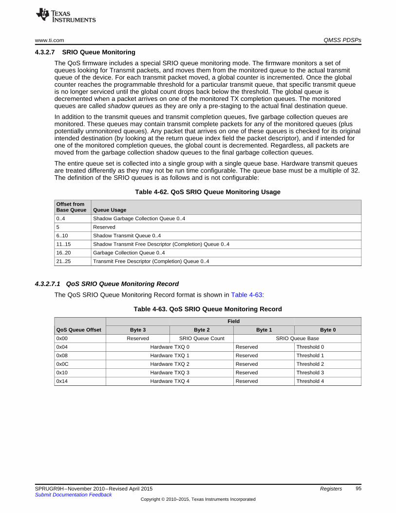
www.ti.com QMSS PDSPs
4.3.2.7 SRIO Queue MonitoringThe QoS firmware includes a special SRIO queue monitoring mode. The firmware monitors a set ofqueues looking for Transmit packets, and moves them from the monitored queue to the actual transmitqueue of the device. For each transmit packet moved, a global counter is incremented. Once the globalcounter reaches the programmable threshold for a particular transmit queue, that specific transmit queueis no longer serviced until the global count drops back below the threshold. The global queue isdecremented when a packet arrives on one of the monitored TX completion queues. The monitoredqueues are called shadow queues as they are only a pre-staging to the actual final destination queue.
In addition to the transmit queues and transmit completion queues, five garbage collection queues aremonitored. These queues may contain transmit complete packets for any of the monitored queues (pluspotentially unmonitored queues). Any packet that arrives on one of these queues is checked for its originalintended destination (by looking at the return queue index field the packet descriptor), and if intended forone of the monitored completion queues, the global count is decremented. Regardless, all packets aremoved from the garbage collection shadow queues to the final garbage collection queues.
The entire queue set is collected into a single group with a single queue base. Hardware transmit queuesare treated differently as they may not be run time configurable. The queue base must be a multiple of 32.The definition of the SRIO queues is as follows and is not configurable:
Table 4-62. QoS SRIO Queue Monitoring Usage
Offset fromBase Queue Queue Usage0..4 Shadow Garbage Collection Queue 0..45 Reserved6..10 Shadow Transmit Queue 0..411..15 Shadow Transmit Free Descriptor (Completion) Queue 0..416..20 Garbage Collection Queue 0..421..25 Transmit Free Descriptor (Completion) Queue 0..4
4.3.2.7.1 QoS SRIO Queue Monitoring RecordThe QoS SRIO Queue Monitoring Record format is shown in Table 4-63:
Table 4-63. QoS SRIO Queue Monitoring Record
FieldQoS Queue Offset Byte 3 Byte 2 Byte 1 Byte 00x00 Reserved SRIO Queue Count SRIO Queue Base0x04 Hardware TXQ 0 Reserved Threshold 00x08 Hardware TXQ 1 Reserved Threshold 10x0C Hardware TXQ 2 Reserved Threshold 20x10 Hardware TXQ 3 Reserved Threshold 30x14 Hardware TXQ 4 Reserved Threshold 4
95SPRUGR9H–November 2010–Revised April 2015 RegistersSubmit Documentation Feedback
Copyright © 2010–2015, Texas Instruments Incorporated
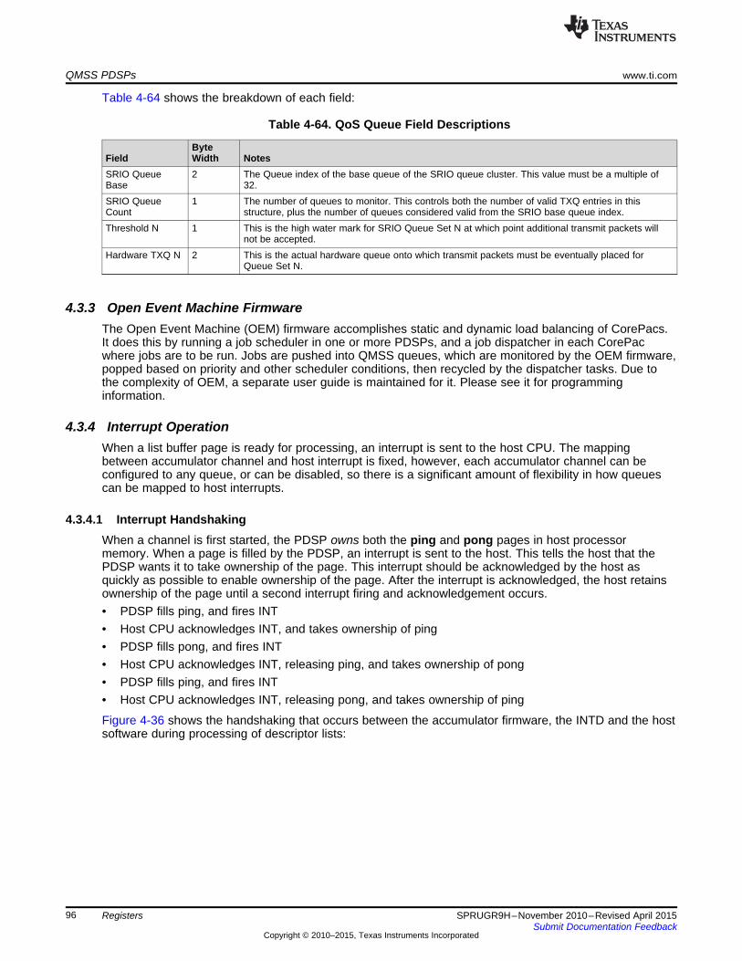
QMSS PDSPs www.ti.com
Table 4-64 shows the breakdown of each field:
Table 4-64. QoS Queue Field Descriptions
ByteField Width NotesSRIO Queue 2 The Queue index of the base queue of the SRIO queue cluster. This value must be a multiple ofBase 32.SRIO Queue 1 The number of queues to monitor. This controls both the number of valid TXQ entries in thisCount structure, plus the number of queues considered valid from the SRIO base queue index.Threshold N 1 This is the high water mark for SRIO Queue Set N at which point additional transmit packets will
not be accepted.Hardware TXQ N 2 This is the actual hardware queue onto which transmit packets must be eventually placed for
Queue Set N.
4.3.3 Open Event Machine FirmwareThe Open Event Machine (OEM) firmware accomplishes static and dynamic load balancing of CorePacs.It does this by running a job scheduler in one or more PDSPs, and a job dispatcher in each CorePacwhere jobs are to be run. Jobs are pushed into QMSS queues, which are monitored by the OEM firmware,popped based on priority and other scheduler conditions, then recycled by the dispatcher tasks. Due tothe complexity of OEM, a separate user guide is maintained for it. Please see it for programminginformation.
4.3.4 Interrupt OperationWhen a list buffer page is ready for processing, an interrupt is sent to the host CPU. The mappingbetween accumulator channel and host interrupt is fixed, however, each accumulator channel can beconfigured to any queue, or can be disabled, so there is a significant amount of flexibility in how queuescan be mapped to host interrupts.
4.3.4.1 Interrupt HandshakingWhen a channel is first started, the PDSP owns both the ping and pong pages in host processormemory. When a page is filled by the PDSP, an interrupt is sent to the host. This tells the host that thePDSP wants it to take ownership of the page. This interrupt should be acknowledged by the host asquickly as possible to enable ownership of the page. After the interrupt is acknowledged, the host retainsownership of the page until a second interrupt firing and acknowledgement occurs.• PDSP fills ping, and fires INT• Host CPU acknowledges INT, and takes ownership of ping• PDSP fills pong, and fires INT• Host CPU acknowledges INT, releasing ping, and takes ownership of pong• PDSP fills ping, and fires INT• Host CPU acknowledges INT, releasing pong, and takes ownership of ping
Figure 4-36 shows the handshaking that occurs between the accumulator firmware, the INTD and the hostsoftware during processing of descriptor lists:
96 Registers SPRUGR9H–November 2010–Revised April 2015Submit Documentation Feedback
Copyright © 2010–2015, Texas Instruments Incorporated

AccumulatorFirmware wants to
trigger interrupt
AccumulatorFirmware reads INTDInt Count Reg(s) todetermine if clear
AccumulatorFirmware writes a bitin INTD Status Reg to
generate interrupt
INTD incrementscount in INTD Int
Count Reg(saturates at 3)
INTD generates Hostinterrupt if previous
interrupt was cleared
INTD decrementscount in INTD Int
Count Reg
INTD clears interruptinternally
When done, Hostwrites EOI value to
EOI register
Host writes a 1 toINTD Int Count Regafter each channel
Optionally, Host writesa bit to INTD Status
Clear Reg
Host processesdescriptor list(s)
Host receivesinterrupt and reads
Status Reg todetermine channels
www.ti.com QMSS PDSPs
Figure 4-36. Handshaking During Processing of Descriptor Lists
4.3.4.2 Interrupt ProcessingWhen a host interrupt fires, the host processor can read a Status register in the INTD to see whichaccumulator channels have list buffer pages ready for processing (see register descriptions in the nextsection). However, the host needs only to process the accumulator channels corresponding to theparticular host interrupt that has fired.
As the host completes processing on a list buffer page, it informs the INTD by writing a 1 to the Int Countregister corresponding to the accumulator channel processed. This tells the firmware that the oppositepage is free to be used to store additional list entries.
Once the host has processed all list buffer pages for all the channels associated with the interrupt, it mustthen perform an EOI by writing the correct value to the INTD EOI register.
4.3.4.3 Interrupt GenerationEach accumulator channel will always trigger an interrupt when all the entries in the current buffer pageare filled. It is also possible to trigger interrupts more quickly by configuring the interrupt pacing mode. Theinterrupt pacing mode allows for interrupts to be generated on a partially filled page, based onconfigurable packet activity and a configurable amount of elapsed time. Note that the pacing is perchannel, and not per interrupt. So, if two channels are using the same host interrupt, then the hostinterrupt can be triggered as each channel independently requires.
The available interrupt pacing modes are based on one of the following events:• Programmable delay since last interrupt to the host• Programmable delay since first packet on new activity• Programmable delay since last packet on new activity
97SPRUGR9H–November 2010–Revised April 2015 RegistersSubmit Documentation Feedback
Copyright © 2010–2015, Texas Instruments Incorporated

QMSS PDSPs www.ti.com
The above event setting determines when the interrupt counter will be loaded and begin its countdown. Aninterrupt will trigger only when both the timing condition is met and there are packets available to forwardto the host. If the timer expires with no packet activity, then the next incoming packet will trigger animmediate interrupt.
The time delay from the configured event is programmable, using the global timer value multiplied by. Atimer setting of 0 seconds is useful in cases where the user wishes to trigger interrupts without delaybased on any packet activity. Note that a delay of 0 seconds will always trigger an immediate interrupt onthe first received packet no matter which of the three configurable pacing events are used.
4.3.4.4 Stall AvoidanceThe accumulator will hold off triggering a second interrupt to the host until any previous interrupt for thatchannel has been serviced. This will help avoid resource starvation.
98 Registers SPRUGR9H–November 2010–Revised April 2015Submit Documentation Feedback
Copyright © 2010–2015, Texas Instruments Incorporated
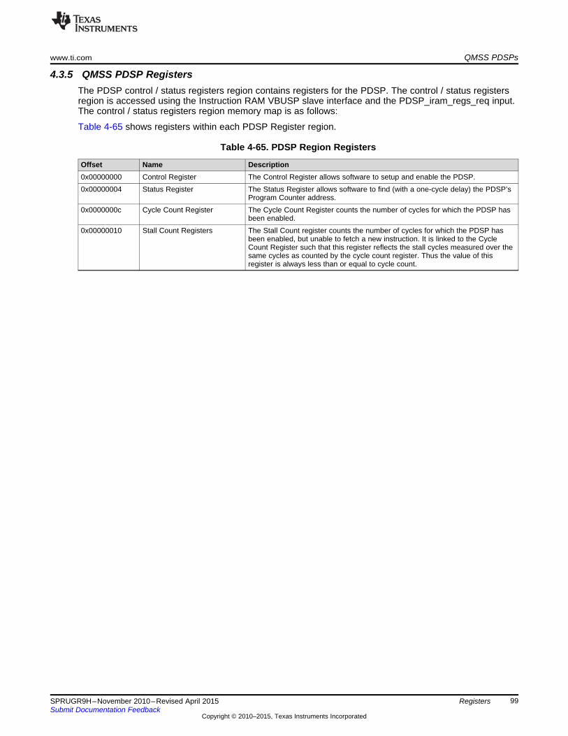
www.ti.com QMSS PDSPs
4.3.5 QMSS PDSP RegistersThe PDSP control / status registers region contains registers for the PDSP. The control / status registersregion is accessed using the Instruction RAM VBUSP slave interface and the PDSP_iram_regs_req input.The control / status registers region memory map is as follows:
Table 4-65 shows registers within each PDSP Register region.
Table 4-65. PDSP Region Registers
Offset Name Description0x00000000 Control Register The Control Register allows software to setup and enable the PDSP.0x00000004 Status Register The Status Register allows software to find (with a one-cycle delay) the PDSP’s
Program Counter address.0x0000000c Cycle Count Register The Cycle Count Register counts the number of cycles for which the PDSP has
been enabled.0x00000010 Stall Count Registers The Stall Count register counts the number of cycles for which the PDSP has
been enabled, but unable to fetch a new instruction. It is linked to the CycleCount Register such that this register reflects the stall cycles measured over thesame cycles as counted by the cycle count register. Thus the value of thisregister is always less than or equal to cycle count.
99SPRUGR9H–November 2010–Revised April 2015 RegistersSubmit Documentation Feedback
Copyright © 2010–2015, Texas Instruments Incorporated

QMSS PDSPs www.ti.com
4.3.5.1 Control Register (0x00000000)The Control Register allows setup and control of the PDSP as shown in Figure 4-37.
Figure 4-37. Control Register (0x00000000)31 16 15 14 13 9 8 7 4 3 2 1 0
PC_RESET STATE BIG Reserved STEP Reserved C_EN SLP P_EN S_RSTR/W-0 R-0 R-0 R-0 R/W-0 R--0 R/W-0 R/W-0 R/W-0 R-0
Legend: R = Read only; R/W = Read/Write; - n = value after reset
Table 4-66. Control Register Field Descriptions
Bits Field Description31- PC_RESET Program Counter Reset Value: This field controls the address where the PDSP will start executing code from after it16 is taken out of reset.15 STATE Run State: This bit indicates whether the PDSP is currently executing an instruction or is halted.
• 0 = PDSP is halted and host has access to the instruction RAM and debug registers regions.• 1 = PDSP is currently running and the host is locked out of the instruction RAM and debug registers regionsThis bit is used by an external debug agent to know when the PDSP has actually halted when waiting for a HALTinstruction to execute, a single step to finish, or any other time when the P_EN has been cleared.
14 BIG Big Endian state. Returns the mode that the PDSP is in.• 0 = Little Endian• 1 = Big Endian
13-9 Reserved Reads return 0 and writes have no effect8 STEP Single Step Enable - This bit controls whether or not the PDSP will execute only a single instruction when enabled.
• 0 = PDSP will free run when enabled• 1 = PDSP will execute a single instruction and then the pdsp_enable bit will be cleared.Note that this bit does not actually enable the PDSP, it only sets the policy for how much code will be run after thePDSP is enabled. The P_EN bit must be explicitly asserted. It is expressly legal to initialize both the STEP andP_EN bits simultaneously. (Two independent writes are not required to cause the stated functionality.)
7-4 Reserved Reads return 0 and writes have no effect3 C_EN Cycle counter enable - Enables PDSP cycle counters
• 0 = Counters not enabled• 1 = Counters enabled
2 SLP Processor sleep indicator - This bit indicates whether or not the PDSP is currently asleep.• 0 = PDSP is not asleep• 1 = PDSP is asleepIf this bit is written to a 0, the PDSP will be forced to power up from sleep mode.
1 P_EN Processor Enable - This bit controls whether or not the PDSP is allowed to fetch new instructions• 0 = PDSP is disabled• 1 = PDSP is enabledIf this bit is de-asserted while the PDSP is currently running and has completed the initial cycle of a multi-cycleinstruction (LBxO,SBxO,SCAN, etc.), the current instruction will be allowed to complete before the PDSP pausesexecution. Otherwise, the PDSP will halt immediately.Because of the unpredictability/timing sensitivity of the instruction execution loop, this bit is not a reliable indication ofwhether or not the PDSP is currently running. The STATE bit should be consulted for an absolute indication of therun state of the core.When the PDSP is halted, it's internal state remains coherent therefore this bit can be reasserted without issuing asoftware reset and the PDSP will resume processing exactly where it left off in the instruction stream.
0 S_RST Soft reset — when this bit is cleared, the PDSP will be reset. This bit is set back to 1 on the next cycle after it hasbeen cleared.
100 Registers SPRUGR9H–November 2010–Revised April 2015Submit Documentation Feedback
Copyright © 2010–2015, Texas Instruments Incorporated
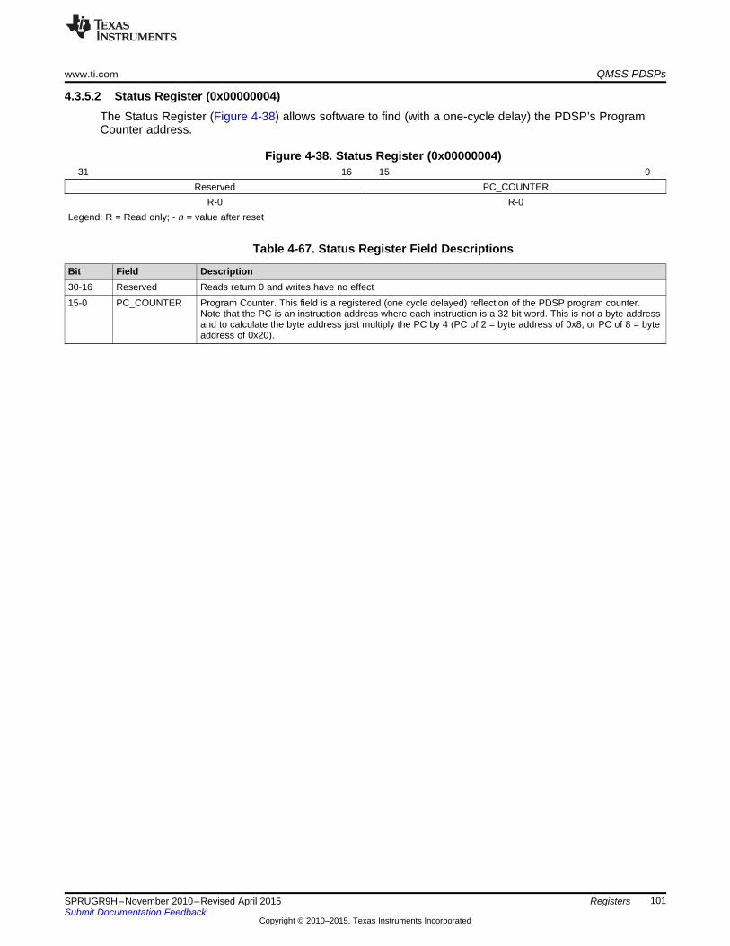
www.ti.com QMSS PDSPs
4.3.5.2 Status Register (0x00000004)The Status Register (Figure 4-38) allows software to find (with a one-cycle delay) the PDSP’s ProgramCounter address.
Figure 4-38. Status Register (0x00000004)31 16 15 0
Reserved PC_COUNTERR-0 R-0
Legend: R = Read only; - n = value after reset
Table 4-67. Status Register Field Descriptions
Bit Field Description30-16 Reserved Reads return 0 and writes have no effect15-0 PC_COUNTER Program Counter. This field is a registered (one cycle delayed) reflection of the PDSP program counter.
Note that the PC is an instruction address where each instruction is a 32 bit word. This is not a byte addressand to calculate the byte address just multiply the PC by 4 (PC of 2 = byte address of 0x8, or PC of 8 = byteaddress of 0x20).
101SPRUGR9H–November 2010–Revised April 2015 RegistersSubmit Documentation Feedback
Copyright © 2010–2015, Texas Instruments Incorporated
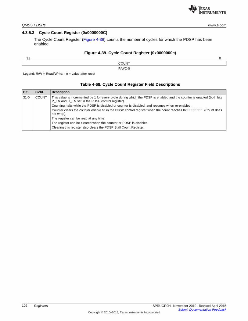
QMSS PDSPs www.ti.com
4.3.5.3 Cycle Count Register (0x0000000C)The Cycle Count Register (Figure 4-39) counts the number of cycles for which the PDSP has beenenabled.
Figure 4-39. Cycle Count Register (0x0000000c)31 0
COUNTR/WC-0
Legend: R/W = Read/Write; - n = value after reset
Table 4-68. Cycle Count Register Field Descriptions
Bit Field Description31-0 COUNT This value is incremented by 1 for every cycle during which the PDSP is enabled and the counter is enabled (both bits
P_EN and C_EN set in the PDSP control register).Counting halts while the PDSP is disabled or counter is disabled, and resumes when re-enabled.Counter clears the counter enable bit in the PDSP control register when the count reaches 0xFFFFFFFF. (Count doesnot wrap).The register can be read at any time.The register can be cleared when the counter or PDSP is disabled.Clearing this register also clears the PDSP Stall Count Register.
102 Registers SPRUGR9H–November 2010–Revised April 2015Submit Documentation Feedback
Copyright © 2010–2015, Texas Instruments Incorporated

www.ti.com QMSS PDSPs
4.3.5.4 Stall Count Register (0x00000010)The Stall Count Register (Figure 4-40) counts cycles for which the PDSP has been enabled, but unable tofetch a new instruction. It is linked to the Cycle Count Register (0x0C) such that this register reflects thestall cycles measured over the same cycles as counted by the cycle count register. Thus the value of thisregister is always less than or equal to cycle count.
Figure 4-40. Stall Count Register (0x00000010)31 0
COUNTR-0
Legend: R = Read only; - n = value after reset
Table 4-69. Stall Count Register Field Descriptions
Bit Field Description31-0 COUNT This value is incremented by 1 for every cycle during which the PDSP is enabled and the counter is enabled (both bits
P_EN and C_EN set in the PDSP control register), and the PDSP was unable to fetch a new instruction for any reason.Counting halts while the PDSP is disabled or the counter is disabled, and resumes when re-enabled.The register can be read at any time.The register is cleared when PDSP Cycle Count Register is cleared.
103SPRUGR9H–November 2010–Revised April 2015 RegistersSubmit Documentation Feedback
Copyright © 2010–2015, Texas Instruments Incorporated

QMSS Interrupt Distributor www.ti.com
4.4 QMSS Interrupt DistributorThe queue manager sub system contains an interrupt distributor to route QMSS interrupts to theCorePacs. The QMSS’ INTD is a subset of the full INTD specification, and only those registers that aremapped and have functionality in QMSS are described in the following sections.
4.4.1 INTD Register RegionTable 4-70 shows registers within the INTD config region.
Table 4-70. INTD Region Registers
Offset Name Description0x00000000 Revision Register The Revision Register contains the major and minor revisions for the INTD
module.0x00000010 End of Interrupt Register The EOI Register allows software to clear specific interrupts within the INTD
module. Unless interrupts have been cleared, they will not trigger again. Eachinterrupt within QMSS is cleared by writing a specific 8-bit value to the register.Writing to this register does not clear corresponding bits in the StatusRegisters, nor does it clear interrupts within the CorePac’s interrupt controller.When the EOI is written, the interrupt will trigger again if the corresponding IntCount Register is not 0, (this should not happen with firmware generatedinterrupts).
0x00000200, Status Registers 0, 1, 2, 3, 4 An array of five registers that provide status on the interrupts managed by the204, 208, 20c, INTD. Registers 2 and 3 are not used in the QMSS INTD. Registers 0, 1, and 4210 expose one bit per QMSS interrupt (see each individual register layout).
Reading the registers returns a 1 bit for each interrupt that has been triggered.Writing to the registers causes an interrupt to be triggered for each set (1) bitjust as if the corresponding input interrupt had arrived.
0x00000280, Status Clear Registers 0, 1, 4 An array of five registers that provide status on the interrupts managed by the284, 290 INTD. Registers 2 and 3 are not used in the QMSS INTD. Registers 0, 1, and 4
expose one bit per QMSS interrupt (see each individual register layout).Reading the registers returns a 1 bit for each interrupt that has been triggered.Writing to the registers causes status bits to be cleared. Clearing status bitsdoes not affect the count of interrupts in the Int Count Registers, nor does itclear the interrupt internally (the EOI register still needs to be written). In blockswhere a single event can represent multiple grouped interrupts, these registerscan be used to determine which interrupts have triggered. Because QMSSdoes not group interrupts, this is needed only to keep it clear which eventshave been processed.
0x00000300 to Interrupt N Count Registers An array of fifty registers, one per QMSS interrupt. Each register contains a3C4 count of the interrupts that have triggered and not processed. In QMSS, this
count saturates at 3. Reading the register returns the count. Writing a non-zerovalue to the register subtracts that value from the count. Writing a 0 clears thecount.
104 Registers SPRUGR9H–November 2010–Revised April 2015Submit Documentation Feedback
Copyright © 2010–2015, Texas Instruments Incorporated

www.ti.com QMSS Interrupt Distributor
4.4.1.1 Revision Register (0x00000000)The Revision Register contains the major and minor revisions for the module as shown in Figure 4-41.
Figure 4-41. Revision Register (0x00000000)31 30 29 28 27 16 15 11 10 8 7 6 5 0SCHEME Reserved MODULE REVRTL REVMAJ REVCUSTOM REVMIN
R-1 R-0 R-0xe83 R-16 R-1 R-0 R-0Legend: R = Read only; - n = value after reset
Table 4-71. Revision Register Field Descriptions
Bits Field Description31-30 SCHEME Scheme that this register is compliant with29-28 Reserved Reads return 0 and writes have no effect27-16 MODULE Function15-11 REVRTL RTL revision10-8 REVMAJ Major revision7-6 REVCUSTOM Custom revision5-0 REVMIN Minor revision
105SPRUGR9H–November 2010–Revised April 2015 RegistersSubmit Documentation Feedback
Copyright © 2010–2015, Texas Instruments Incorporated
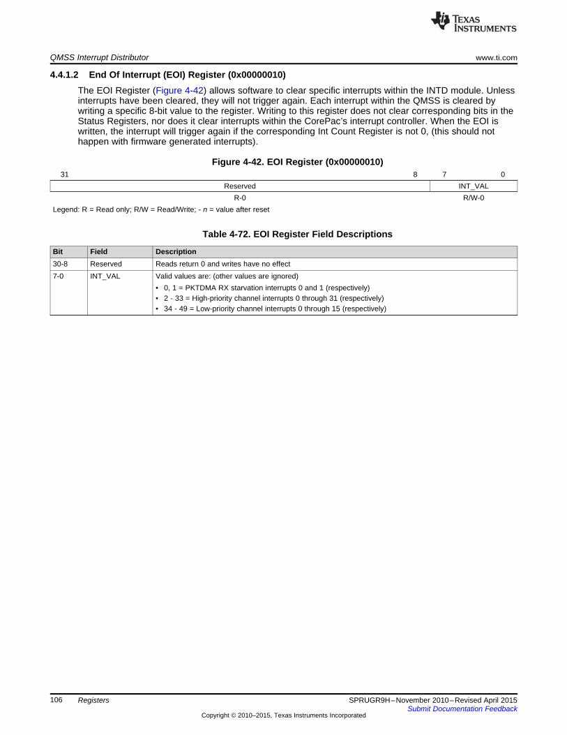
QMSS Interrupt Distributor www.ti.com
4.4.1.2 End Of Interrupt (EOI) Register (0x00000010)The EOI Register (Figure 4-42) allows software to clear specific interrupts within the INTD module. Unlessinterrupts have been cleared, they will not trigger again. Each interrupt within the QMSS is cleared bywriting a specific 8-bit value to the register. Writing to this register does not clear corresponding bits in theStatus Registers, nor does it clear interrupts within the CorePac’s interrupt controller. When the EOI iswritten, the interrupt will trigger again if the corresponding Int Count Register is not 0, (this should nothappen with firmware generated interrupts).
Figure 4-42. EOI Register (0x00000010)31 8 7 0
Reserved INT_VALR-0 R/W-0
Legend: R = Read only; R/W = Read/Write; - n = value after reset
Table 4-72. EOI Register Field Descriptions
Bit Field Description30-8 Reserved Reads return 0 and writes have no effect7-0 INT_VAL Valid values are: (other values are ignored)
• 0, 1 = PKTDMA RX starvation interrupts 0 and 1 (respectively)• 2 - 33 = High-priority channel interrupts 0 through 31 (respectively)• 34 - 49 = Low-priority channel interrupts 0 through 15 (respectively)
106 Registers SPRUGR9H–November 2010–Revised April 2015Submit Documentation Feedback
Copyright © 2010–2015, Texas Instruments Incorporated
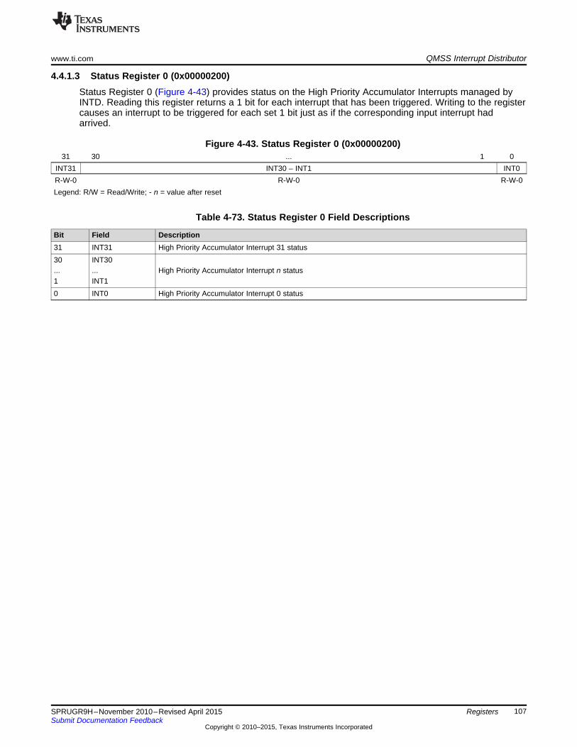
www.ti.com QMSS Interrupt Distributor
4.4.1.3 Status Register 0 (0x00000200)Status Register 0 (Figure 4-43) provides status on the High Priority Accumulator Interrupts managed byINTD. Reading this register returns a 1 bit for each interrupt that has been triggered. Writing to the registercauses an interrupt to be triggered for each set 1 bit just as if the corresponding input interrupt hadarrived.
Figure 4-43. Status Register 0 (0x00000200)31 30 ... 1 0
INT31 INT30 – INT1 INT0R-W-0 R-W-0 R-W-0Legend: R/W = Read/Write; - n = value after reset
Table 4-73. Status Register 0 Field Descriptions
Bit Field Description31 INT31 High Priority Accumulator Interrupt 31 status30 INT30... ... High Priority Accumulator Interrupt n status1 INT10 INT0 High Priority Accumulator Interrupt 0 status
107SPRUGR9H–November 2010–Revised April 2015 RegistersSubmit Documentation Feedback
Copyright © 2010–2015, Texas Instruments Incorporated

QMSS Interrupt Distributor www.ti.com
4.4.1.4 Status Register 1 (0x00000204)Status Register 1 (Figure 4-44) provides status on the Low Priority Accumulator Interrupts managed byINTD. Reading this register returns a 1 bit for each interrupt that has been triggered. Writing to the registercauses an interrupt to be triggered for each set 1 bit just as if the corresponding input interrupt hadarrived.
Figure 4-44. Status Register 1 (0x00000204)31 16 15 14 ... 1 0
Reserved INT15 INT14 – INT1 INT0R-0 R/W-0 R/W-0 R/W-0
Legend: R = Read only; R/W = Read/Write; - n = value after reset
Table 4-74. Status Register 1 Field Descriptions
Bit Field Description31-16 Reserved Reads return 0 and writes have no effect15 INT15 Low Priority Accumulator Interrupt 15 status14 INT14 ...... INT1 Low Priority Accumulator Interrupt n status10 INT0 Low Priority Accumulator Interrupt 0 status
108 Registers SPRUGR9H–November 2010–Revised April 2015Submit Documentation Feedback
Copyright © 2010–2015, Texas Instruments Incorporated
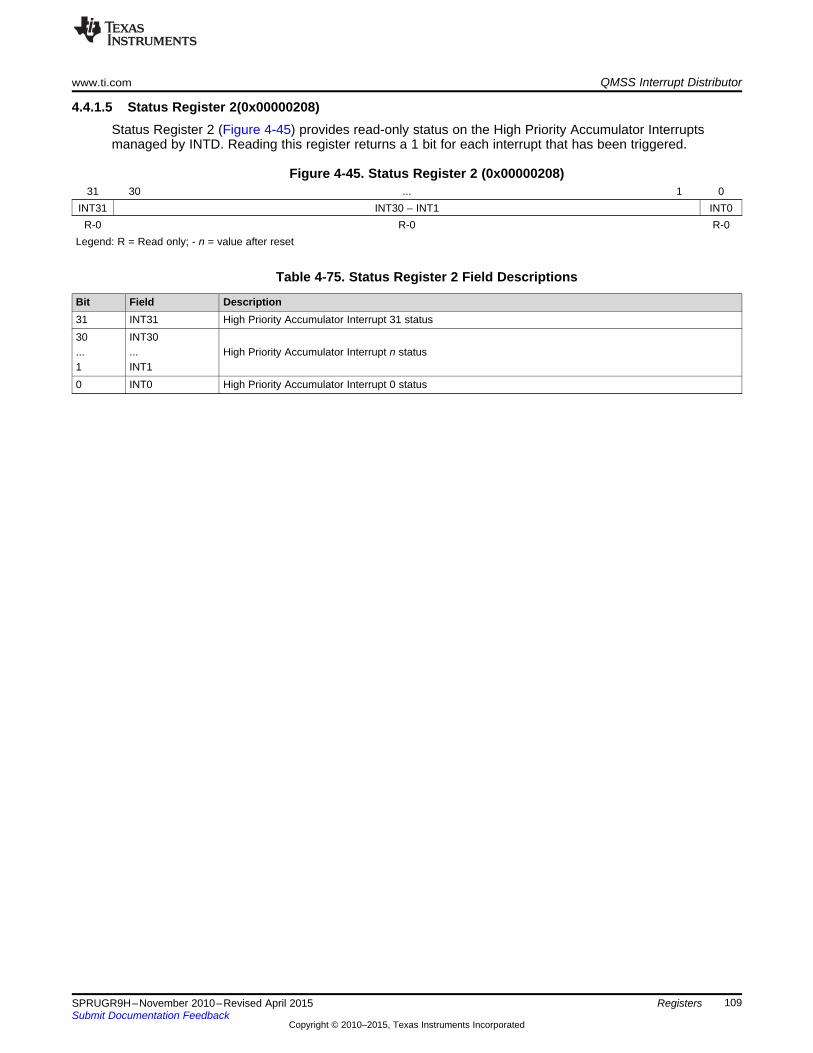
www.ti.com QMSS Interrupt Distributor
4.4.1.5 Status Register 2(0x00000208)Status Register 2 (Figure 4-45) provides read-only status on the High Priority Accumulator Interruptsmanaged by INTD. Reading this register returns a 1 bit for each interrupt that has been triggered.
Figure 4-45. Status Register 2 (0x00000208)31 30 ... 1 0
INT31 INT30 – INT1 INT0R-0 R-0 R-0
Legend: R = Read only; - n = value after reset
Table 4-75. Status Register 2 Field Descriptions
Bit Field Description31 INT31 High Priority Accumulator Interrupt 31 status30 INT30... ... High Priority Accumulator Interrupt n status1 INT10 INT0 High Priority Accumulator Interrupt 0 status
109SPRUGR9H–November 2010–Revised April 2015 RegistersSubmit Documentation Feedback
Copyright © 2010–2015, Texas Instruments Incorporated

QMSS Interrupt Distributor www.ti.com
4.4.1.6 Status Register 3(0x0000020c)Status Register 1 (Figure 4-46) provides read-only status on the Low Priority Accumulator Interruptsmanaged by INTD. Reading this register returns a 1 bit for each interrupt that has been triggered.
Figure 4-46. Status Register 3 (0x0000020c)31 16 15 14 ... 1 0
Reserved INT15 INT14 – INT1 INT0R-0 R-0 R-0 R-0
Legend: R = Read only; - n = value after reset
Table 4-76. Status Register 1 Field Descriptions
Bit Field Description31-16 Reserved Reads return 0 and writes have no effect15 INT15 Low Priority Accumulator Interrupt 15 status14 INT14 ...... INT1 Low Priority Accumulator Interrupt n status10 INT0 Low Priority Accumulator Interrupt 0 status
110 Registers SPRUGR9H–November 2010–Revised April 2015Submit Documentation Feedback
Copyright © 2010–2015, Texas Instruments Incorporated
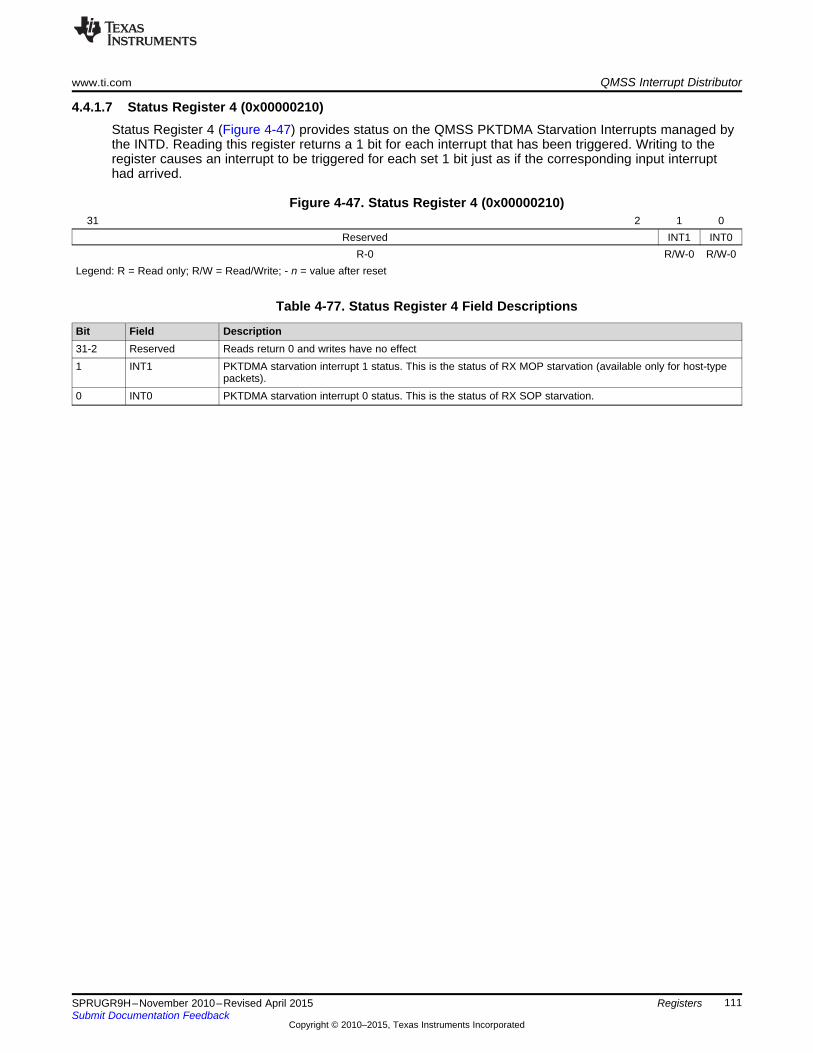
www.ti.com QMSS Interrupt Distributor
4.4.1.7 Status Register 4 (0x00000210)Status Register 4 (Figure 4-47) provides status on the QMSS PKTDMA Starvation Interrupts managed bythe INTD. Reading this register returns a 1 bit for each interrupt that has been triggered. Writing to theregister causes an interrupt to be triggered for each set 1 bit just as if the corresponding input interrupthad arrived.
Figure 4-47. Status Register 4 (0x00000210)31 2 1 0
Reserved INT1 INT0R-0 R/W-0 R/W-0
Legend: R = Read only; R/W = Read/Write; - n = value after reset
Table 4-77. Status Register 4 Field Descriptions
Bit Field Description31-2 Reserved Reads return 0 and writes have no effect1 INT1 PKTDMA starvation interrupt 1 status. This is the status of RX MOP starvation (available only for host-type
packets).0 INT0 PKTDMA starvation interrupt 0 status. This is the status of RX SOP starvation.
111SPRUGR9H–November 2010–Revised April 2015 RegistersSubmit Documentation Feedback
Copyright © 2010–2015, Texas Instruments Incorporated

QMSS Interrupt Distributor www.ti.com
4.4.1.8 Status Clear Register 0 (0x00000280)Status Register 0 (Figure 4-48) provides status on the high-priority accumulator interrupts managed by theINTD. Reading this register returns a 1 bit for each interrupt that has been triggered. Writing to the registercauses status bits to be cleared. Clearing status bits does not affect the count of interrupts in the Int CountRegisters, nor does it clear the interrupt internally (the EOI register still needs to be written). In blockswhere a single event can represent multiple grouped interrupts, these registers can be used to determinewhich interrupts have triggered. Because the QMSS does not group interrupts, this is needed only to keepclear which events have been processed (it is optional).
Figure 4-48. Status Clear Register 0 (0x00000280)31 30 ... 1 0
INT31 INT30 ... INT1 INT0R/W-0 R/W-0 R/W-0Legend: R/W = Read/Write; - n = value after reset
Table 4-78. Status Clear Register 0 Field Descriptions
Bit Field Description31 INT31 High Priority Accumulator Interrupt 31 status30 INT30... ... High Priority Accumulator Interrupt n status1 INT10 INT0 High Priority Accumulator Interrupt 0 status
112 Registers SPRUGR9H–November 2010–Revised April 2015Submit Documentation Feedback
Copyright © 2010–2015, Texas Instruments Incorporated

www.ti.com QMSS Interrupt Distributor
4.4.1.9 Status Clear Register 1 (0x00000284)Status Register 1 (Figure 4-49) provides status on the low-priority accumulator interrupts managed by theINTD. Reading this register returns a 1 bit for each interrupt that has been triggered. Writing to the registercauses status bits to be cleared. Clearing status bits does not affect the count of interrupts in the Int CountRegisters, nor does it clear the interrupt internally (the EOI register still needs to be written). In blockswhere a single event can represent multiple grouped interrupts, these registers can be used to determinewhich interrupts have triggered. Because the QMSS does not group interrupts, this is needed only to keepclear which events have been processed (it is optional).
Figure 4-49. Status Clear Register 1 (0x00000284)31 16 15 14 ... 1 0
Reserved INT15 INT14 ... INT1 INT0R-0 R/W-0 R/W-0 R/W-0
Legend: R = Read only; R/W = Read/Write; - n = value after reset
Table 4-79. Status Clear Register 1 Field Descriptions
Bit Field Description31-16 Reserved Reads return 0 and writes have no effect15 INT15 Low Priority Accumulator Interrupt 15 status14 INT14... ... Low Priority Accumulator Interrupt n status1 INT10 INT0 Low Priority Accumulator Interrupt 0 status
113SPRUGR9H–November 2010–Revised April 2015 RegistersSubmit Documentation Feedback
Copyright © 2010–2015, Texas Instruments Incorporated

QMSS Interrupt Distributor www.ti.com
4.4.1.10 Status Clear Register 4 (0x00000290)Status Register 4 (Figure 4-50) provides status on the QMSS PKTDMA starvation interrupts managed bythe INTD. Reading this register returns a 1 bit for each interrupt that has been triggered. Writing to theregister causes status bits to be cleared. Clearing status bits does not affect the count of interrupts in theInt Count Registers, nor does it clear the interrupt internally (the EOI register still needs to be written). Inblocks where a single event can represent multiple grouped interrupts, these registers can be used todetermine which interrupts have triggered. Because the QMSS does not group interrupts, this is neededonly to keep clear which events have been processed (it is optional).
Figure 4-50. Status Clear Register 4 (0x00000290)31 2 1 0
Reserved INT1 INT0R-0 R/W-0 R/W-0
Legend: R = Read only; R/W = Read/Write; - n = value after reset
Table 4-80. Status Clear Register 4 Field Descriptions
Bit Field Description31-2 Reserved Reads return 0 and writes have no effect1 INT1 PKTDMA Starvation Interrupt 1 status. This clears the status of RX MOP starvation (available only for host-
type packets).0 INT0 PKTDMA Starvation Interrupt 0 status. This clears the status of RX SOP starvation.
114 Registers SPRUGR9H–November 2010–Revised April 2015Submit Documentation Feedback
Copyright © 2010–2015, Texas Instruments Incorporated

www.ti.com QMSS Interrupt Distributor
4.4.1.11 Interrupt N Count Register (0x00000300 + 4xN)The Interrupt N Count Registers (Figure 4-51) each contains a count of the interrupts that have triggeredand not been processed. In the QMSS, this count saturates at 3. Reading the register returns the count.Writing a non-0 value to the register subtracts that value from the count. Writing a 0 clears the count.Note, clearing the count does not clear the interrupt (the EOI Register still needs to be written). Theseregisters are mapped in the following order:• 0x0300 to 0x037C: High Priority Accumulator Interrupts 0 to 31 (respectively)• 0x0380 to 0x03BC: Low Priority Accumulator Interrupts 0 to 15 (respectively)• 0x03C0 to 0x03C4: QMSS PKTDMA RX Starvation Interrupts 0 to 1 (respectively)
Figure 4-51. Int N Count Register (0x00000300 + 4xN)31 2 1 0
Reserved INT_COUNTR-0 R/W-0
Legend: R = Read only; R/W = Read/Write; - n = value after reset
Table 4-81. Int N Count Register Field Descriptions
Bit Field Description30-2 Reserved Reads return 0 and writes have no effect1-0 INT_COUNT Count of non-acknowledged interrupts.
115SPRUGR9H–November 2010–Revised April 2015 RegistersSubmit Documentation Feedback
Copyright © 2010–2015, Texas Instruments Incorporated
QMSS Interrupt Distributor www.ti.com
116 Registers SPRUGR9H–November 2010–Revised April 2015Submit Documentation Feedback
Copyright © 2010–2015, Texas Instruments Incorporated
Chapter 5SPRUGR9H–November 2010–Revised April 2015
Mapping Information
This chapter covers the mapping of Multicore Navigator resources in the device. The resources describedhere include the mapping of queues, packet DMA (PKTDMA) channels, accumulator interrupts, andmemory (memory mapped register region offsets).
Topic ........................................................................................................................... Page
5.1 Queue Maps..................................................................................................... 1185.2 Interrupt Maps.................................................................................................. 1205.3 Memory Maps................................................................................................... 1235.4 Packet DMA Channel Map.................................................................................. 125
117SPRUGR9H–November 2010–Revised April 2015 Mapping InformationSubmit Documentation Feedback
Copyright © 2010–2015, Texas Instruments Incorporated

Queue Maps www.ti.com
5.1 Queue MapsThe queue manager supports a total of 8192 queues (16k for KeyStone II). Most of them are available forgeneral purpose use, but some are dedicated for special use, and in some cases, have special hardwarefunctionality associated with them. Queues not listed are general purpose queues.
NOTE: Any queue that is not used by the application for hardware purposes may be used as ageneral purpose queue. You must only ensure that the corresponding hardware functionalityis not enabled. For example, if Low Priority accumulation is not used, queues 0 to 511 maybe used as general purpose queues.
Table 5-1. Queue Map for KeyStone I
TCI660x TCI6618TCI6616 / C667x / C6670 TCI6614 C665xQueues Queues Queues Queues Queues Purpose0 to 511 Same Same Same Same Normally used by low priority accumulation. The low priority accumulator(512) uses up to 512 queues divided into 16 channels, each channel being 32
continuous queues. Each channel triggers one broadcast interrupt. Thesequeues can also be used as general purpose queues.
512 to Same Same Same AIF2 TX queues. Each queue has a dedicated queue pending signal that639 drives a TX DMA channel.(128)640 to Same Same Same NetCP TX queues. Each queue has a dedicated queue pending signal that648 (9) drives a TX DMA channel.
650-657 ARM queue pend queues. These queues have dedicated queue pending(8) signals wired directly to the ARM.
662 to 652 to 662 to 662 to INTC0/INTC1 queue pend queues. These queues have dedicated queue671 (10) 671 (20) 671 (10) 671 (10) pending signals wired directly into the chip level INTC0 and/or INTC1. Note
that the event mapping can differ for each device.670-671 ARM queue pend queues. These queues have dedicated queue pending(2) signals wired directly to the ARM. Note that these are also routed to INTC0.
672 to Same Same Same Same SRIO TX queues. Each queue has a dedicated queue pending signal that687 (16) drives a TX DMA channel.688 to Same Same Same FFTC_A, B TX queues. Each queue has a dedicated queue pending signal695 (8) that drives a TX DMA channel.704 to Same Same Same Same Normally used by high priority accumulation. The high priority accumulator735 (32) uses up to 32 queues, one per channel. Each channel triggers a core-
specific interrupt. These queues can also be used as general purposequeues.
736 to Same Same Same Same Queues with starvation counters readable by the host. Starvation counters799 (64) increment each time a pop is performed on an empty queue, and reset when
the starvation count is read.800 to Same Same Same Same QMSS TX queues. Used for infrastructure (core to core) DMA copies and831 (32) notification.832 to Same Same Same Same General purpose queues, or may be configured for use by QoS traffic863 (32) shaping firmware.
864 to FFTC_C TX queues. Each queue has a dedicated queue pending signal that867 (4) drives a TX DMA channel.
864 to Same Same Same Same HyperLink queue pend queues. These queues have dedicated queue895 (32) pending signals wired directly into HyperLink. On some devices, these
overlap. They cannot be simultaneously used for both IP (i.e. use queue 864for either FFTC_C or Hyperlink).
868 to 864 to BCP TX queues. Each queue has a dedicated queue pending signal that875 (8) 871 (8) drives a TX DMA channel. Also routed to HyperLink.
896 to Same Same Same Same General purpose. Due to the mapping of logical to physical queues in the8191 PKTDMA interfaces, the use of 0xFFF in PKTDMA qnum fields is reserved
to specify non-override conditions.
118 Mapping Information SPRUGR9H–November 2010–Revised April 2015Submit Documentation Feedback
Copyright © 2010–2015, Texas Instruments Incorporated
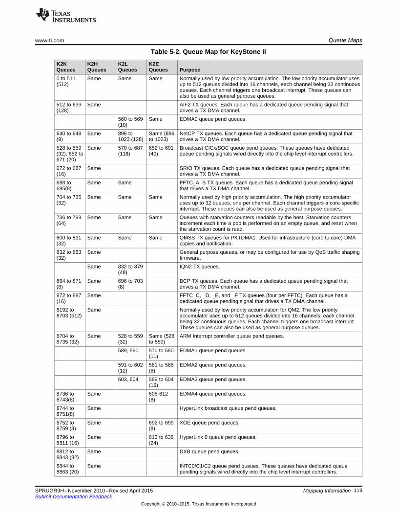
www.ti.com Queue Maps
Table 5-2. Queue Map for KeyStone II
K2K K2H K2L K2EQueues Queues Queues Queues Purpose0 to 511 Same Same Same Normally used by low priority accumulation. The low priority accumulator uses(512) up to 512 queues divided into 16 channels, each channel being 32 continuous
queues. Each channel triggers one broadcast interrupt. These queues canalso be used as general purpose queues.
512 to 639 Same AIF2 TX queues. Each queue has a dedicated queue pending signal that(128) drives a TX DMA channel.
560 to 569 Same EDMA0 queue pend queues.(10)
640 to 648 Same 896 to Same (896 NetCP TX queues. Each queue has a dedicated queue pending signal that(9) 1023 (128) to 1023) drives a TX DMA channel.528 to 559 Same 570 to 687 652 to 691 Broadcast CICx/SOC queue pend queues. These queues have dedicated(32), 652 to (118) (40) queue pending signals wired directly into the chip level interrupt controllers.671 (20)672 to 687 Same SRIO TX queues. Each queue has a dedicated queue pending signal that(16) drives a TX DMA channel.688 to Same Same FFTC_A, B TX queues. Each queue has a dedicated queue pending signal695(8) that drives a TX DMA channel.704 to 735 Same Same Same Normally used by high priority accumulation. The high priority accumulator(32) uses up to 32 queues, one per channel. Each channel triggers a core-specific
interrupt. These queues can also be used as general purpose queues.736 to 799 Same Same Same Queues with starvation counters readable by the host. Starvation counters(64) increment each time a pop is performed on an empty queue, and reset when
the starvation count is read.800 to 831 Same Same Same QMSS TX queues for PKTDMA1. Used for infrastructure (core to core) DMA(32) copies and notification.832 to 863 Same General purpose queues, or may be configured for use by QoS traffic shaping(32) firmware.
Same 832 to 879 IQN2 TX queues.(48)
864 to 871 Same 696 to 703 BCP TX queues. Each queue has a dedicated queue pending signal that(8) (8) drives a TX DMA channel.872 to 887 Same FFTC_C, _D, _E, and _F TX queues (four per FFTC). Each queue has a(16) dedicated queue pending signal that drives a TX DMA channel.8192 to Same Normally used by low priority accumulation for QM2. The low priority8703 (512) accumulator uses up to 512 queues divided into 16 channels, each channel
being 32 continuous queues. Each channel triggers one broadcast interrupt.These queues can also be used as general purpose queues.
8704 to Same 528 to 559 Same (528 ARM Interrupt controller queue pend queues.8735 (32) (32) to 559)
589, 590 570 to 580 EDMA1 queue pend queues.(11)
591 to 602 581 to 588 EDMA2 queue pend queues.(12) (8)603, 604 589 to 604 EDMA3 queue pend queues.
(16)8736 to Same 605-612 EDMA4 queue pend queues.8743(8) (8)8744 to Same HyperLink broadcast queue pend queues.8751(8)8752 to Same 692 to 699 XGE queue pend queues.8759 (8) (8)8796 to Same 613 to 636 HyperLink 0 queue pend queues.8811 (16) (24)8812 to Same DXB queue pend queues.8843 (32)8844 to Same INTC0/C1/C2 queue pend queues. These queues have dedicated queue8863 (20) pending signals wired directly into the chip level interrupt controllers.
119SPRUGR9H–November 2010–Revised April 2015 Mapping InformationSubmit Documentation Feedback
Copyright © 2010–2015, Texas Instruments Incorporated

Interrupt Maps www.ti.com
Table 5-2. Queue Map for KeyStone II (continued)K2K K2H K2L K2EQueues Queues Queues Queues Purpose8864 to Same HyperLink 1 queue pend queues.8879 (16)8896 to Same Normally used by high priority accumulation for QM2. The high priority8927 (32) accumulator uses up to 32 queues, one per channel. Each channel triggers a
core-specific interrupt. These queues can also be used as general purposequeues.
8928 to Same Queues with starvation counters readable by the host. Starvation counters8991 (64) increment each time a pop is performed on an empty queue, and reset when
the starvation count is read.8992 to Same QMSS TX queues for PKTDMA2. Used for infrastructure (core to core) DMA9023 (32) copies and notification.9024 to Same General purpose queues.16383
5.2 Interrupt Maps
5.2.1 KeyStone I TCI661x, C6670, C665x devicesTable 5-3 shows the mapping of queues to high priority accumulation channels to DSP and function forTCI661x (16, 18, 14), C6670 and C665x devices. Note that each queue and event maps to a specific DSPcore. Also, the queues shown are the suggested mapping. Other queues may be used. The channel toevent mapping is fixed.
Table 5-3. High Priority Queue Mapping (TCI661x, C6670 C665x)
DSP Queue High Priority Channel Interrupt Name DSP Eventcore N 704 + N N qmss_intr1_0+N 48(N = 0 to 3) 708 + N N + 4 qmss_intr1_4+N 49
712 + N N + 8 qmss_intr1_8+N 50716 + N N + 12 qmss_intr1_12+N 51720 + N N + 16 qmss_intr1_16+N 52724 + N N + 20 qmss_intr1_20+N 53728 + N N + 24 qmss_intr1_24+N 54732 + N N + 28 qmss_intr1_28+N 55
The C665x devices have 1 or 2 DSPs, so Table 5-3 shows the mapping of queues to high priorityaccumulation channels where N=0 or 1, which maps only half of the high priority channels. Table 5-4shows the mapping of the remaining channels, which, in effect, doubles interrupts to each core.
Table 5-4. High Priority Queue Mapping (C665x part 2)
DSP Queue High Priority Channel Interrupt Name DSP Eventcore N 706 + N N + 2 qmss_intr1_2+N 102(N = 0 to 1) 710 + N N + 6 qmss_intr1_6+N 103
714 + N N + 10 qmss_intr1_10+N 104718 + N N + 14 qmss_intr1_14+N 105722 + N N + 18 qmss_intr1_18+N 106726 + N N + 22 qmss_intr1_22+N 107730 + N N + 26 qmss_intr1_26+N 108734 + N N + 30 qmss_intr1_30+N 109
120 Mapping Information SPRUGR9H–November 2010–Revised April 2015Submit Documentation Feedback
Copyright © 2010–2015, Texas Instruments Incorporated
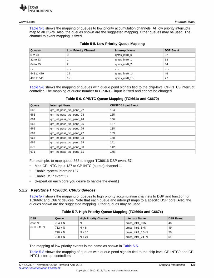
www.ti.com Interrupt Maps
Table 5-5 shows the mapping of queues to low priority accumulation channels. All low priority interruptsmap to all DSPs. Also, the queues shown are the suggested mapping. Other queues may be used. Thechannel to event mapping is fixed.
Table 5-5. Low Priority Queue Mapping
Queues Low Priority Channel Interrupt Name DSP Event0 to 31 0 qmss_intr0_0 3232 to 63 1 qmss_intr0_1 3364 to 95 2 qmss_intr0_2 34. . . . . . . . . . . .448 to 479 14 qmss_intr0_14 46480 to 511 15 qmss_intr0_15 47
Table 5-6 shows the mapping of queues with queue pend signals tied to the chip-level CP-INTC0 interruptcontroller. The mapping of queue number to CP-INTC input is fixed and cannot be changed.
Table 5-6. CPINTC Queue Mapping (TCI661x and C6670)
Queue Interrupt Name CPINTC0 Input Event662 qm_int_pass_txq_pend_22 134663 qm_int_pass_txq_pend_23 135664 qm_int_pass_txq_pend_24 136665 qm_int_pass_txq_pend_25 137666 qm_int_pass_txq_pend_26 138667 qm_int_pass_txq_pend_27 139668 qm_int_pass_txq_pend_28 140669 qm_int_pass_txq_pend_29 141670 qm_int_pass_txq_pend_30 142671 qm_int_pass_txq_pend_31 175
For example, to map queue 665 to trigger TCI6616 DSP event 57:• Map CP-INTC input 137 to CP-INTC (output) channel 1.• Enable system interrupt 137.• Enable DSP event 57.• (Repeat on each core you desire to handle the event.)
5.2.2 KeyStone I TCI660x, C667x devicesTable 5-7 shows the mapping of queues to high priority accumulation channels to DSP and function forTCI660x and C667x devices. Note that each queue and interrupt maps to a specific DSP core. Also, thequeues shown are the suggested mapping. Other queues may be used.
Table 5-7. High Priority Queue Mapping (TCI660x and C667x)
DSP Queue High Priority Channel Interrupt Name DSP Eventcore N 704 + N N qmss_intr1_0+N 48(N = 0 to 7) 712 + N N + 8 qmss_intr1_8+N 49
720 + N N + 16 qmss_intr1_16+N 50728 + N N + 24 qmss_intr1_24+N 51
The mapping of low priority events is the same as shown in Table 5-5.
Table 5-8 shows the mapping of queues with queue pend signals tied to the chip-level CP-INTC0 and CP-INTC1 interrupt controllers.
121SPRUGR9H–November 2010–Revised April 2015 Mapping InformationSubmit Documentation Feedback
Copyright © 2010–2015, Texas Instruments Incorporated
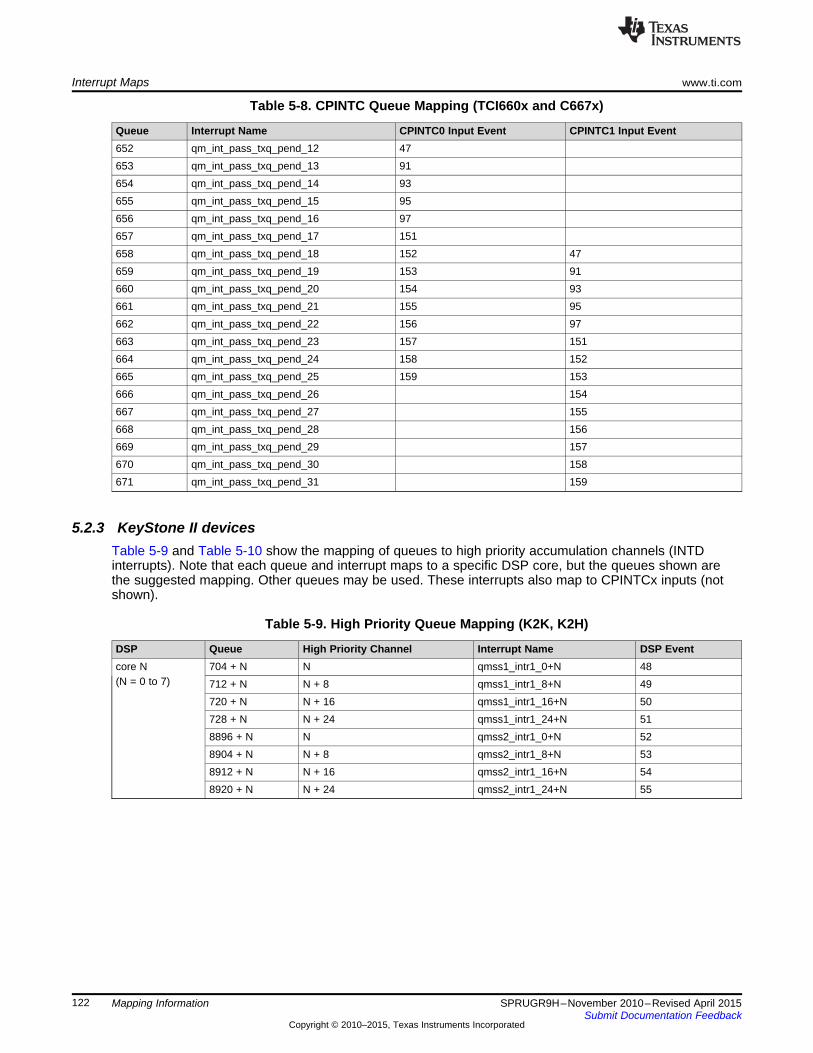
Interrupt Maps www.ti.com
Table 5-8. CPINTC Queue Mapping (TCI660x and C667x)
Queue Interrupt Name CPINTC0 Input Event CPINTC1 Input Event652 qm_int_pass_txq_pend_12 47653 qm_int_pass_txq_pend_13 91654 qm_int_pass_txq_pend_14 93655 qm_int_pass_txq_pend_15 95656 qm_int_pass_txq_pend_16 97657 qm_int_pass_txq_pend_17 151658 qm_int_pass_txq_pend_18 152 47659 qm_int_pass_txq_pend_19 153 91660 qm_int_pass_txq_pend_20 154 93661 qm_int_pass_txq_pend_21 155 95662 qm_int_pass_txq_pend_22 156 97663 qm_int_pass_txq_pend_23 157 151664 qm_int_pass_txq_pend_24 158 152665 qm_int_pass_txq_pend_25 159 153666 qm_int_pass_txq_pend_26 154667 qm_int_pass_txq_pend_27 155668 qm_int_pass_txq_pend_28 156669 qm_int_pass_txq_pend_29 157670 qm_int_pass_txq_pend_30 158671 qm_int_pass_txq_pend_31 159
5.2.3 KeyStone II devicesTable 5-9 and Table 5-10 show the mapping of queues to high priority accumulation channels (INTDinterrupts). Note that each queue and interrupt maps to a specific DSP core, but the queues shown arethe suggested mapping. Other queues may be used. These interrupts also map to CPINTCx inputs (notshown).
Table 5-9. High Priority Queue Mapping (K2K, K2H)
DSP Queue High Priority Channel Interrupt Name DSP Eventcore N 704 + N N qmss1_intr1_0+N 48(N = 0 to 7) 712 + N N + 8 qmss1_intr1_8+N 49
720 + N N + 16 qmss1_intr1_16+N 50728 + N N + 24 qmss1_intr1_24+N 518896 + N N qmss2_intr1_0+N 528904 + N N + 8 qmss2_intr1_8+N 538912 + N N + 16 qmss2_intr1_16+N 548920 + N N + 24 qmss2_intr1_24+N 55
122 Mapping Information SPRUGR9H–November 2010–Revised April 2015Submit Documentation Feedback
Copyright © 2010–2015, Texas Instruments Incorporated
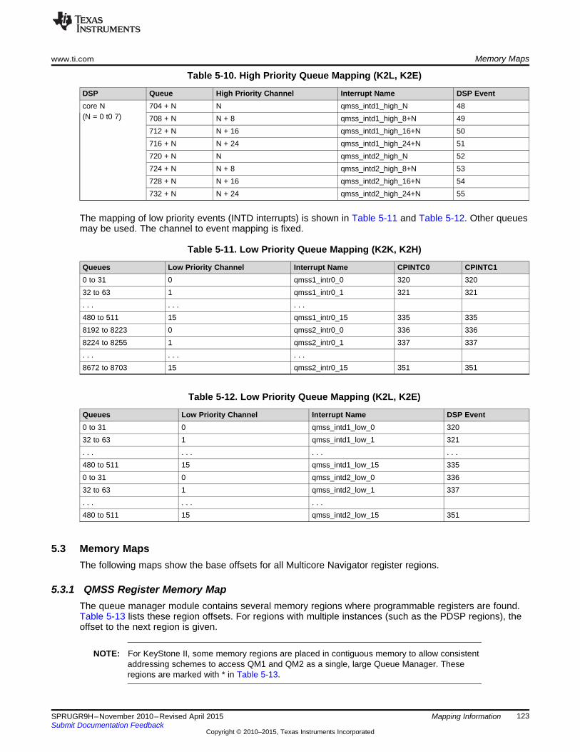
www.ti.com Memory Maps
Table 5-10. High Priority Queue Mapping (K2L, K2E)
DSP Queue High Priority Channel Interrupt Name DSP Eventcore N 704 + N N qmss_intd1_high_N 48(N = 0 t0 7) 708 + N N + 8 qmss_intd1_high_8+N 49
712 + N N + 16 qmss_intd1_high_16+N 50716 + N N + 24 qmss_intd1_high_24+N 51720 + N N qmss_intd2_high_N 52724 + N N + 8 qmss_intd2_high_8+N 53728 + N N + 16 qmss_intd2_high_16+N 54732 + N N + 24 qmss_intd2_high_24+N 55
The mapping of low priority events (INTD interrupts) is shown in Table 5-11 and Table 5-12. Other queuesmay be used. The channel to event mapping is fixed.
Table 5-11. Low Priority Queue Mapping (K2K, K2H)
Queues Low Priority Channel Interrupt Name CPINTC0 CPINTC10 to 31 0 qmss1_intr0_0 320 32032 to 63 1 qmss1_intr0_1 321 321. . . . . . . . .480 to 511 15 qmss1_intr0_15 335 3358192 to 8223 0 qmss2_intr0_0 336 3368224 to 8255 1 qmss2_intr0_1 337 337. . . . . . . . .8672 to 8703 15 qmss2_intr0_15 351 351
Table 5-12. Low Priority Queue Mapping (K2L, K2E)
Queues Low Priority Channel Interrupt Name DSP Event0 to 31 0 qmss_intd1_low_0 32032 to 63 1 qmss_intd1_low_1 321. . . . . . . . . . . .480 to 511 15 qmss_intd1_low_15 3350 to 31 0 qmss_intd2_low_0 33632 to 63 1 qmss_intd2_low_1 337. . . . . . . . .480 to 511 15 qmss_intd2_low_15 351
5.3 Memory MapsThe following maps show the base offsets for all Multicore Navigator register regions.
5.3.1 QMSS Register Memory MapThe queue manager module contains several memory regions where programmable registers are found.Table 5-13 lists these region offsets. For regions with multiple instances (such as the PDSP regions), theoffset to the next region is given.
NOTE: For KeyStone II, some memory regions are placed in contiguous memory to allow consistentaddressing schemes to access QM1 and QM2 as a single, large Queue Manager. Theseregions are marked with * in Table 5-13.
123SPRUGR9H–November 2010–Revised April 2015 Mapping InformationSubmit Documentation Feedback
Copyright © 2010–2015, Texas Instruments Incorporated
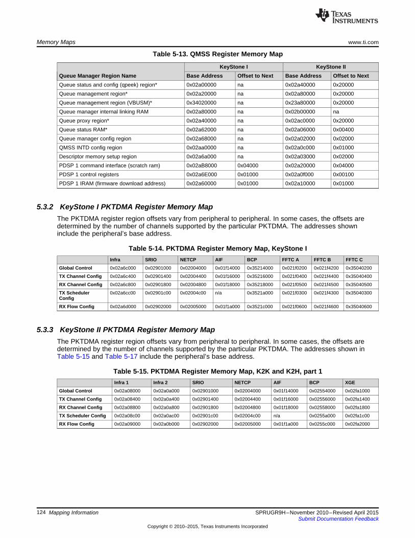
Memory Maps www.ti.com
Table 5-13. QMSS Register Memory Map
KeyStone I KeyStone IIQueue Manager Region Name Base Address Offset to Next Base Address Offset to NextQueue status and config (qpeek) region* 0x02a00000 na 0x02a40000 0x20000Queue management region* 0x02a20000 na 0x02a80000 0x20000Queue management region (VBUSM)* 0x34020000 na 0x23a80000 0x20000Queue manager internal linking RAM 0x02a80000 na 0x02b00000 naQueue proxy region* 0x02a40000 na 0x02ac0000 0x20000Queue status RAM* 0x02a62000 na 0x02a06000 0x00400Queue manager config region 0x02a68000 na 0x02a02000 0x02000QMSS INTD config region 0x02aa0000 na 0x02a0c000 0x01000Descriptor memory setup region 0x02a6a000 na 0x02a03000 0x02000PDSP 1 command interface (scratch ram) 0x02aB8000 0x04000 0x02a20000 0x04000PDSP 1 control registers 0x02a6E000 0x01000 0x02a0f000 0x00100PDSP 1 IRAM (firmware download address) 0x02a60000 0x01000 0x02a10000 0x01000
5.3.2 KeyStone I PKTDMA Register Memory MapThe PKTDMA register region offsets vary from peripheral to peripheral. In some cases, the offsets aredetermined by the number of channels supported by the particular PKTDMA. The addresses showninclude the peripheral’s base address.
Table 5-14. PKTDMA Register Memory Map, KeyStone IInfra SRIO NETCP AIF BCP FFTC A FFTC B FFTC C
Global Control 0x02a6c000 0x02901000 0x02004000 0x01f14000 0x35214000 0x021f0200 0x021f4200 0x35040200
TX Channel Config 0x02a6c400 0x02901400 0x02004400 0x01f16000 0x35216000 0x021f0400 0x021f4400 0x35040400
RX Channel Config 0x02a6c800 0x02901800 0x02004800 0x01f18000 0x35218000 0x021f0500 0x021f4500 0x35040500
TX Scheduler 0x02a6cc00 0x02901c00 0x02004c00 n/a 0x3521a000 0x021f0300 0x021f4300 0x35040300Config
RX Flow Config 0x02a6d000 0x02902000 0x02005000 0x01f1a000 0x3521c000 0x021f0600 0x021f4600 0x35040600
5.3.3 KeyStone II PKTDMA Register Memory MapThe PKTDMA register region offsets vary from peripheral to peripheral. In some cases, the offsets aredetermined by the number of channels supported by the particular PKTDMA. The addresses shown inTable 5-15 and Table 5-17 include the peripheral’s base address.
Table 5-15. PKTDMA Register Memory Map, K2K and K2H, part 1Infra 1 Infra 2 SRIO NETCP AIF BCP XGE
Global Control 0x02a08000 0x02a0a000 0x02901000 0x02004000 0x01f14000 0x02554000 0x02fa1000
TX Channel Config 0x02a08400 0x02a0a400 0x02901400 0x02004400 0x01f16000 0x02556000 0x02fa1400
RX Channel Config 0x02a08800 0x02a0a800 0x02901800 0x02004800 0x01f18000 0x02558000 0x02fa1800
TX Scheduler Config 0x02a08c00 0x02a0ac00 0x02901c00 0x02004c00 n/a 0x0255a000 0x02fa1c00
RX Flow Config 0x02a09000 0x02a0b000 0x02902000 0x02005000 0x01f1a000 0x0255c000 0x02fa2000
124 Mapping Information SPRUGR9H–November 2010–Revised April 2015Submit Documentation Feedback
Copyright © 2010–2015, Texas Instruments Incorporated

www.ti.com Packet DMA Channel Map
Table 5-16. PKTDMA Register Memory Map, K2L, part 1
Infra NETCP NETCP (local) IQN2 BCPGlobal Control 0x02a08000 0x26004000 0x26182000 0x27104000 0x02554000
TX Channel Config 0x02a08400 0x26004400 0x26183000 0x27106000 0x02556000RX Channel Config 0x02a08800 0x26004800 0x26184000 0x27108000 0x02558000
TX Scheduler Config 0x02a08c00 0x26004c00 0x26182100 0x2710a000 0x0255a000RX Flow Config 0x02a09000 0x26005000 0x26185000 02710c000 0x0255c000
Table 5-17. PKTDMA Register Memory Map, K2K, K2H and K2L, part 2
FFTC 0 FFTC 1 FFTC 2 FFTC 3 FFTC 4 FFTC 5Global Control 0x021f0200 0x021f4200 0x021f8200 0x021fc200 0x021f0a00 0x021f1200
TX Channel Config 0x021f0400 0x021f4400 0x021f8400 0x021fc400 0x021f0c00 0x021f1400RX Channel Config 0x021f0500 0x021f4500 0x021f8500 0x021fc500 0x021f0d00 0x021f1500
TX Scheduler Config 0x021f0300 0x021f4300 0x021f8300 0x021fc300 0x021f0b00 0x021f1300RX Flow Config 0x021f0600 0x021f4600 0x021f8600 0x021fc600 0x021f0e00 0x021f1600
Table 5-18. PKTDMA Register Memory Map, K2E
Infra NETCP NETCP (local) XGEGlobal Control 0x02a08000 0x24004000 0x24182000 0x02fa1000
TX Channel Config 0x02a08400 0x24004400 0x24183000 0x02fa1400RX Channel Config 0x02a08800 0x24004800 0x24184000 0x02fa1800
TX Scheduler Config 0x02a08c00 0x24004c00 0x24182100 0x02fa1c00RX Flow Config 0x02a09000 0x24005000 0x24185000 0x02fa2000
5.4 Packet DMA Channel MapEach instance of the PKTDMA contains a different number of channels and flows. Table 5-19 specifies thenumber for each PKTDMA.
Table 5-19. PKTDMA Channel Map
QMSS SRIO NETCP1 NETCP 1.5 AIF IQN2 BCP XGE FFTCRX Channels 32 16 24 91 129 48 8 16 4TX Channels 32 16 9 21 129 48 8 8 4
RX Flows 64 20 32 64 129 64 64 32 8
125SPRUGR9H–November 2010–Revised April 2015 Mapping InformationSubmit Documentation Feedback
Copyright © 2010–2015, Texas Instruments Incorporated

Packet DMA Channel Map www.ti.com
126 Mapping Information SPRUGR9H–November 2010–Revised April 2015Submit Documentation Feedback
Copyright © 2010–2015, Texas Instruments Incorporated
Chapter 6SPRUGR9H–November 2010–Revised April 2015
Programming Information
This chapter presents register-level sample code to perform basic Multicore Navigator tasks. It alsodiscusses system planning considerations that should be performed when designing Multicore Navigator’suse within an application. Please note that low-level drivers (LLD) are available for Multicore Navigator,but their use is beyond the scope of this document.
Topic ........................................................................................................................... Page
6.1 Programming Considerations ............................................................................ 1286.2 Example Code .................................................................................................. 1296.3 Programming Overrides .................................................................................... 1356.4 Programming Errors ......................................................................................... 1356.5 Questions and Answers .................................................................................... 137
127SPRUGR9H–November 2010–Revised April 2015 Programming InformationSubmit Documentation Feedback
Copyright © 2010–2015, Texas Instruments Incorporated
Programming Considerations www.ti.com
6.1 Programming Considerations
6.1.1 System PlanningMulticore Navigator is a complex peripheral to program due to its many setup options and its connectionsto other system peripherals. This requires thorough, coordinated planning on how to allocate MulticoreNavigator resources for whatever uses the system will require of it. For best efficiency, Multicore Navigatoris designed to be initialized at system start with an allocation of resources large enough to support it andnot to be reconfigured at run-time, though there is support for this (such as the teardown of PKTDMAchannels). Resources requiring up-front consideration are:1. Descriptor memories. First, the decision for using host or monolithic packets must be made
(generally, monolithic are simpler to use, but host provide more flexibility). Next, the sizes of thedescriptor memories must be considered. The QM can be configured with 20 different descriptorregions, and each region supports only one descriptor size. (Note, for monolithic use this means amaximum of 20 different descriptor sizes can be specified; for host mode, the linked buffers can still beany size). Finally, the required number of descriptors must be known. Because descriptors can berecycled both in TX and RX transactions, extra descriptors are needed to make sure the free descriptorpools do not run dry (a condition called starvation).
2. Queue allocation. With more than 7,300 general purpose queues, it should not be difficult to organizea functional layout of queues. Because the QM does not access any part of the descriptor or databuffers, there is no penalty for using one queue over another (though the placement of descriptormemory in L2 or DDR will have performance effects). Also, remember that each TX queue will requirea TX completion queue and RX queues require free descriptor queues. It is possible though to haveseveral TX queues completing to a common TX completion queue, and the same for RX queues.Another consideration is the powerful use of chaining – the output queue of one peripheral being theinput queue of another, and so on. This requires careful planning of queue use and recycling.
3. System memory. With the allocation of descriptors comes the obvious need to allocate and partitionchunks of memory for descriptor and buffer use, and also the decision of which memories (L2, DDR,etc.) to use. Another less obvious consideration is the programming of the descriptor region itself: Thedescriptor size must be a multiple of 16 bytes, and the number of descriptors in the region is specifiedas a power or 2, beginning with 25. These restrict the region’s possible size, especially when largenumbers of descriptors are required.
4. TIP1: You can program a descriptor region that is larger than you allocate memory for, but the region’sstart indexes and the link RAM sizes must be consistent with the programmed values. This will meanallocating a larger link RAM than will be used, but this is more than offset by not allocating the full sizedescriptor region. In other words, programming a larger than actual descriptor region helps to getaround the coarse power of 2 sizing of the region. Caveats to this:(a) You must make absolutely sure that no other memory region resides within the programmed
memory space of another region.(b) You can use these phantom descriptors in the QM only, because the QM does not touch memory.
But you must not try to pass them through the PKTDMA.5. TIP2: You must program a descriptor region with a fixed size, but you do not have to use every
descriptor. As long as each descriptor is a multiple of the programmed size (which, itself, is a multipleof 16 bytes), you can use contiguous descriptors to create a single larger descriptor. The host mustmanage how it tracks the different sized descriptors.
6. RX flows. RX flows can have a powerful effect on memory usage. Through careful programming, theRX DMA can be configured to select a particular FDQ based on packet size, or by Host buffer numberwithin the packet.
7. Recycling and garbage collection. Descriptor fields provide for specifying which queues thedescriptors should be recycled to once the TX DMA has finished with them. It is recommended to usethis feature in TX transfers. For RX, the host is responsible for requiring descriptors to the RX FDQ.
128 Programming Information SPRUGR9H–November 2010–Revised April 2015Submit Documentation Feedback
Copyright © 2010–2015, Texas Instruments Incorporated
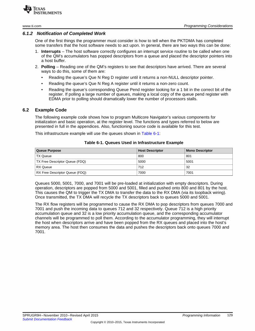
www.ti.com Programming Considerations
6.1.2 Notification of Completed WorkOne of the first things the programmer must consider is how to tell when the PKTDMA has completedsome transfers that the host software needs to act upon. In general, there are two ways this can be done:1. Interrupts – The host software correctly configures an interrupt service routine to be called when one
of the QM’s accumulators has popped descriptors from a queue and placed the descriptor pointers intoa host buffer.
2. Polling – Reading one of the QM’s registers to see that descriptors have arrived. There are severalways to do this, some of them are:• Reading the queue’s Que N Reg D register until it returns a non-NULL descriptor pointer.• Reading the queue’s Que N Reg A register until it returns a non-zero count.• Reading the queue’s corresponding Queue Pend register looking for a 1 bit in the correct bit of the
register. If polling a large number of queues, making a local copy of the queue pend register withEDMA prior to polling should dramatically lower the number of processors stalls.
6.2 Example CodeThe following example code shows how to program Multicore Navigator’s various components forinitialization and basic operation, at the register level. The functions and types referred to below arepresented in full in the appendices. Also, functioning source code is available for this test.
This infrastructure example will use the queues shown in Table 6-1:
Table 6-1. Queues Used in Infrastructure Example
Queue Purpose Host Descriptor Mono DescriptorTX Queue 800 801TX Free Descriptor Queue (FDQ) 5000 5001RX Queue 712 32RX Free Descriptor Queue (FDQ) 7000 7001
Queues 5000, 5001, 7000, and 7001 will be pre-loaded at initialization with empty descriptors. Duringoperation, descriptors are popped from 5000 and 5001, filled and pushed onto 800 and 801 by the host.This causes the QM to trigger the TX DMA to transfer the data to the RX DMA (via its loopback wiring).Once transmitted, the TX DMA will recycle the TX descriptors back to queues 5000 and 5001.
The RX flow registers will be programmed to cause the RX DMA to pop descriptors from queues 7000 and7001 and push the incoming data to queues 712 and 32 respectively. Queue 712 is a high priorityaccumulation queue and 32 is a low priority accumulation queue, and the corresponding accumulatorchannels will be programmed to poll them. According to the accumulator programming, they will interruptthe host when descriptors arrive and have been popped from the RX queues and placed into the host’smemory area. The host then consumes the data and pushes the descriptors back onto queues 7000 and7001.
129SPRUGR9H–November 2010–Revised April 2015 Programming InformationSubmit Documentation Feedback
Copyright © 2010–2015, Texas Instruments Incorporated
Example Code www.ti.com
6.2.1 QMSS InitializationMulticore Navigator is designed to be initialized at startup with enough resources to keep it runningsuccessfully during normal operation.
First, define memory areas to be used, and align them to 16 byte boundaries (only the QM memoriesrequire alignment, but it is a good idea to align the others as well):
#pragma DATA_ALIGN (host_region, 16)Uint8 host_region[64 * 64];#pragma DATA_ALIGN (mono_region, 16)Uint8 mono_region[32 * 160];#pragma DATA_ALIGN (buffers, 16)Uint32 buffers[64 * 256]; //these buffers are for Host Packets#pragma DATA_ALIGN (hostList, 16)Uint32 hostList[34]; // ping/pong of (16 + 1 word for list count)#pragma DATA_ALIGN (monoList, 16)Uint32 monoList[34]; // ping/pong of (16 + 1 word for list count)
Some declarations for clarity in the following code segments (see appendices for type definitions):
MNAV_HostPacketDescriptor *host_pkt;MNAV_MonolithicPacketDescriptor *mono_pkt;Qmss_AccCmd cmd;
Next, setup the QM memory regions to be used. This example will setup two: one for host descriptors andanother for monolithic descriptors. The part that requires the most attention is specifying the size. The lastparameter writes to the Memory Region Setup Register, and defines the size of the descriptor and thenumber of descriptors (see this register definition in previous sections).
/* Setup Memory Region 0 for 40 56 byte Host descriptors. Our* Host descriptors will be 32 bytes plus up to 6 words of PS data,* but the next best size is 64 bytes times 64 descriptors. */
set_memory_region(0, (Uint32) host_region, 0, 0x00030001);
/* Setup Memory Region 1 for 8 148B Monolithic descriptors. Our* Mono descriptors will be 12 bytes plus 16 bytes of EPIB Info, plus* 128 bytes of payload, but the next best size is 160 bytes times* 32 descriptors. (dead space is possible) */
set_memory_region(1, (Uint32) mono_region, 64, 0x00090000);
An external Linking RAM needs to be configured with one 64-bit word for each descriptor in the memoryregions that use the external Linking RAM. The internal Linking RAM does not require a buffer to beallocated for it.
/****************************************************************** Configure Linking RAM 0 to use the 16k entry internal link ram.*/set_link_ram(0, 0x00080000, 0x3FFF);
Note that Linking RAM 0 may be configured to use internal QMSS memory as shown here. Linking RAM 1may use L2 or DDR. For efficiency reasons, it is best to use the internal QMSS Link RAM memorywhenever possible.
Once the memory regions and Link RAMs have been configured, two types of queues should be filled withempty descriptors: TX completion queues (otherwise known as TX FDQs), and RX FDQs.
/* Initialize descriptor regions to zero */memset(host_region, 0, 64 * 64);
memset(mono_region, 0, 32 * 160);
/* Push Host Descriptors to Tx Completion Queue (FDQ) 5000 */
130 Programming Information SPRUGR9H–November 2010–Revised April 2015Submit Documentation Feedback
Copyright © 2010–2015, Texas Instruments Incorporated
www.ti.com Example Code
for (idx = 0; idx < 20; idx ++){
host_pkt = (MNAV_HostPacketDescriptor *)(host_region + (idx * 64));host_pkt->pkt_return_qmgr = 1;host_pkt->pkt_return_qnum = 0;host_pkt->orig_buff0_len = 64 * 4;host_pkt->orig_buff0_ptr = (Uint32)(buffers + (idx * 128));host_pkt->next_desc_ptr = NULL;
push_queue(5000, 1, 0, (Uint32)(host_pkt));}
/* Push Monolithic packets to Tx Completion Queue (FDQ) 5001 */for (idx = 0; idx < 16; idx ++){
mono_pkt = (MNAV_MonolithicPacketDescriptor *)(mono_region + (idx * 160));mono_pkt->pkt_return_qmgr = 1;
mono_pkt->pkt_return_qnum = 1;
push_queue(5001, 1, 0, (Uint32)(mono_pkt));}
/* Push Host Descriptors to Rx FDQ 7000 */for (idx = 20; idx < 64; idx ++){
host_pkt = (MNAV_HostPacketDescriptor *)(host_region + (idx * 64));
/* Set non-Rx overwrite fields */host_pkt->orig_buff0_len = 64 * 4;host_pkt->orig_buff0_ptr = (Uint32)(buffers + (idx * 128));host_pkt->next_desc_ptr = NULL; //don’t link Host buffers in Rx FDQ
push_queue(7000, 1, 0, (Uint32)(host_pkt));}
/* Push Monolithic packets to Rx FDQ 2001 */for (idx = 16; idx < 32; idx ++){
mono_pkt = (MNAV_MonolithicPacketDescriptor *)(mono_region + (idx * 160));
push_queue(7001, 1, 0, (Uint32)(mono_pkt));}
Last, program the accumulator channels that are needed. Both of these channels are programmed toreturn only the QM Reg D value per descriptor. The high priority program will use the list count methodand the low priority program will use NULL termination. The second time the interrupt triggers, theaccumulators will write to the pong side of the lists (in both cases starting with word 17). It is up to the hostto process and recycle the descriptors before that ping or pong side is needed again by the accumulator(which does not check for consumption).
/****************************************************************** Program a hi-pri accumulation channel for queue 712.*/cmd.command = 0x81; //enablecmd.channel = 8; //will trigger qmss_intr1_8 to core 0cmd.queue_mask = 0; //not used in single modecmd.list_address = (uint32_t)hostList; //address of ping buffercmd.max_entries = 17; //list can hold up to 16 (max-1)cmd.qm_index = 712; //que to monitor for channel 8cmd.cfg_multi_q = 0; //0=single queue modecmd.cfg_list_mode = 1; //1=list count in first entrycmd.cfg_list_size = 0; //0="D" Reg
131SPRUGR9H–November 2010–Revised April 2015 Programming InformationSubmit Documentation Feedback
Copyright © 2010–2015, Texas Instruments Incorporated
Example Code www.ti.com
cmd.cfg_int_delay = 1; //1=delay since last interrupt (pacing mode)cmd.timer_count = 1; //number of timer ticks to delay interrupt
program_accumulator(1, &cmd);
/****************************************************************** Program a lo-pri accumulation channel for queue 32.*/cmd.command = 0x81; //enablecmd.channel = 1; //will trigger qmss_intr0_1 to all corescmd.queue_mask = 0x00000001; //look only at queue 32 for this examplecmd.list_address = (uint32_t)monoList; //address of ping buffercmd.max_entries = 17; //list can hold up to 16 (max-1)cmd.qm_index = 32; //first que to monitor for this channelcmd.cfg_multi_q = 1; //1=multi queue modecmd.cfg_list_mode = 0; //0=NULL terminated listcmd.cfg_list_size = 0; //0="D" Regcmd.cfg_int_delay = 1; //1=delay since last interrupt (pacing mode)cmd.timer_count = 1; //number of timer ticks to delay interrupt
program_accumulator(0, &cmd);
/* Clear the Accumulator lists. */memset(hostList, 0, 34 * 4);memset(monoList, 0, 34 * 4);
6.2.2 PKTDMA InitializationIn this example, two PKTDMA channels (for both TX and RX) are configured with one RX flow perchannel. The following code shows the necessary initialization.
First, configure the logical queue managers. We will define three in this example: (note this is not theusual configuration, this is mainly for demonstration).
/* Program the logical queue managers for QMSS PKTDMA: */qm_map[0] = 0;
qm_map[1] = 5000;qm_map[2] = 7000;qm_map[3] = 0xffff; /* unused */
config_pktdma_qm(QMSS_pktdma_GBL_CFG_REGION, qm_map);
Next, configure the TX channels. TX channels should not be configured while they are enabled.
/* Configure Tx channel 0 */config_tx_sched(QMSS_PKTDMA_TX_SCHD_REGION, 0, 0); //high priority
/* Configure Tx channel 1 */config_tx_sched(QMSS_PKTDMA_TX_SCHD_REGION, 1, 0); //high priority
Next, configure the RX flows. Note that RX flows cannot be changed while any channel that uses themare enabled. This is not trivial for simple example code to check, so config_rx_flow simply assumes thatno RX channels are enabled. It is well worth the investment in time to study the programmability of the RXflow. For example, FDQ selection may be fixed, based on packet size, or in the case of Host packets,Host buffer number. In the case of size based FDQ selection, RX Flow registers C through H must beprogrammed to configure the thresholds, enables and desired queues.
This example sets up the basic case – select from one FDQ and send to one RX queue:
/* Configure Rx flow 0 for channel 0 (Host Descriptors to Hi Pri Acc.) */config_rx_flow(QMSS_PKTDMA_RX_FLOW_REGION, 0,
0x040002c8, 0, 0, 0x20002000, 0x20002000, 0, 0, 0);
/* Configure Rx flow 1 for channel 1 (Mono Descriptors to Lo Pri Acc.) */config_rx_flow(QMSS_PKTDMA_RX_FLOW_REGION, 1,
0x080c0020, 0, 0, 0x20012001, 0, 0, 0, 0);
132 Programming Information SPRUGR9H–November 2010–Revised April 2015Submit Documentation Feedback
Copyright © 2010–2015, Texas Instruments Incorporated

www.ti.com Example Code
Last, enable the RX and TX channels that have been configured.
/* Enable the Tx and Rx channels */enable_tx_chan(QMSS_PKTDMA_TX_CHAN_REGION, 0, 0x80000000);enable_tx_chan(QMSS_PKTDMA_TX_CHAN_REGION, 1, 0x80000000);enable_rx_chan(QMSS_PKTDMA_RX_CHAN_REGION, 0, 0x80000000);enable_rx_chan(QMSS_PKTDMA_RX_CHAN_REGION, 1, 0x80000000);
6.2.3 Normal Infrastructure DMA with AccumulationAt this point, everything has been initialized for the example test case. All that remains to be done is:1. Pop descriptors from the TX completion (FDQ) queues.2. Fill the descriptor fields and buffers with some data.3. Push the filled descriptors onto the TX queues.4. Wait for the accumulators to complete popping the RX queues and building the descriptor lists.
The following code will push 8 descriptors into the TX queues then wait for the results:
for (idx = 0; idx < 8; idx ++){
Uint32 tmp = pop_queue(5000);host_pkt = (MNAV_HostPacketDescriptor *)(tmp);host_pkt->type_id = MNAV_DESC_ID_HOST;host_pkt->ps_reg_loc = 0;host_pkt->packet_length = 64;host_pkt->psv_word_count = 0;host_pkt->pkt_return_qnum = 0x1000;host_pkt->buffer_len = 64;
host_pkt->next_desc_ptr = NULL;host_pkt->src_tag_lo = 0; //copied to .flo_idx of streaming i/f/* Add code here to fill the descriptor's buffer */
push_queue(800, 1, 0, tmp);
tmp = pop_queue(5001);mono_pkt = (MNAV_MonolithicPacketDescriptor *)(tmp);mono_pkt->type_id = MNAV_DESC_ID_MONO;mono_pkt->data_offset = 12;mono_pkt->packet_length = 16;mono_pkt->epib = 0;mono_pkt->pkt_return_qnum = 0x1001;mono_pkt->src_tag_lo = 1; //copied to .flo_idx of streaming i/f/* Add code here to fill the descriptor's buffer */
push_queue(801, 1, 0, tmp);}
/* Burn some time for the accumulators to run. */testpass = 0;for (idx = 0; idx < 20000; idx ++){
testpass = idx;}
Because no data was loaded into buffers, there is no need to check for that here. But, check to see thatthe correct descriptors arrived in the resulting host descriptor and monolithic descriptor lists. Note that thedescriptors in these lists no longer belong to any queue. It is the host’s responsibility to requeue them.
testpass = 1;/* Check the Host Packet accumulator list. */for (idx = 0; idx < 8; idx ++){
133SPRUGR9H–November 2010–Revised April 2015 Programming InformationSubmit Documentation Feedback
Copyright © 2010–2015, Texas Instruments Incorporated

Example Code www.ti.com
addr = (Uint32)(host_region + ((idx + 16) * 64));if (hostList[idx+1] != addr)
testpass = 0;}
if (hostList[0] != 8) //check the list count in element 0testpass = 0;
if (testpass == 1)printf("Host Descriptor Test: PASS\n");
elseprintf("Host Descriptor Test: FAIL\n");
testpass = 1;/* Check the Monolithic Packet accumulator list. */for (idx = 0; idx < 8; idx ++){
addr = (Uint32)(mono_region + ((idx + 16) * 160));if (monoList[idx] != addr)
testpass = 0;}
if (monoList[8] != 0) //check for the NULL terminator in this listtestpass = 0;
if (testpass == 1)printf("Monolithic Descriptor Test: PASS\n");
elseprintf("Monolithic Descriptor Test: FAIL\n");
6.2.4 Bypass Infrastructure notification with AccumulationIn this mode, the PKTDMA is bypassed because there is no data to transmit (or the data has been placedin a shared memory buffer available to both the source and destination cores). Descriptors will be poppedoff the RX FDQs, and pushed directly onto the RX queues, causing the accumulators to act on them.
Using the same QM Initialization as shown in Section 6.2.1, and no required PKTDMA initialization, it ispossible to pop directly from the RX FDQ, and push to the accumulation queues and achieve the sameresults. The descriptors can be uninitialized if desired (because the QM does not look at them), but theycan be used to pass information from source to destination.
for (idx = 0; idx < 8; idx ++){
Uint32 tmp = pop_queue(7000);host_pkt = (MNAV_HostPacketDescriptor *)(tmp);host_pkt->type_id = MNAV_DESC_ID_HOST;host_pkt->buffer_ptr = (Uint32)buffers; //this can point to a shared bufferhost_pkt->next_desc_ptr = NULL;
push_queue(712, 1, 0, tmp);
tmp = pop_queue(7001);mono_pkt = (MNAV_MonolithicPacketDescriptor *)(tmp);mono_pkt->type_id = MNAV_DESC_ID_MONO;push_queue(32, 1, 0, tmp);
}
/* Burn some time for the accumulators to run. */testpass = 0;for (idx = 0; idx < 20000; idx ++){
testpass = idx;}
134 Programming Information SPRUGR9H–November 2010–Revised April 2015Submit Documentation Feedback
Copyright © 2010–2015, Texas Instruments Incorporated
www.ti.com Example Code
6.2.5 Channel TeardownTo perform a channel teardown, the host must do the following:1. When the host desires to teardown a channel (either RX or TX), it writes a 1 to the teardown field of
the corresponding RX or TX Channel Global Configuration Register for that channel. The host shouldnot disable the channel by writing a 0 to the enable field of this register. The PKTDMA will do thiswhen finished with the teardown.
When the PKTDMA detects the teardown bit is set, it will:
TX Teardown RX Teardown
• Allow the current packet to complete normally. • Signals the attached peripheral (rx_teardown_req) that ateardown was requested by the Host.• Clear the channel enable bit in the TX Channel Global
Configuration Register. The teardown bit will remain set • Waits for the peripheral to acknowledgeas an indication that a teardown was performed. (rx_teardown_ack).
• Notes:– During this time, processing continues normally.– In some peripherals, rx_teardown_req and
rx_teardown_ack are tied together in loopback.• Following ack, the current packet is allowed to complete
normally.• Clear the channel enable in the RX Channel Global
Configuration Register. The teardown bit will remain setas an indication that a teardown was performed.
The host detects the teardown is complete by examining the RX/TX Channel Global ConfigurationRegister to check the enable status.
6.3 Programming OverridesThe following is a list of ways to override the default programming methods. The programmer should payattention to these, because if done incorrectly, the PKTDMA may not function as expected and may bedifficult to debug.1. Streaming I/F Overrides:
(a) flow_index. A value of 0xFFFF (or a value >= the number of RX Flows) will cause the RX DMA touse the channel (thread) number for flow_index. So, an RX Flow is always used, even if notdirectly specified.
(b) dest_qnum. A value of 0x1FFF is the normal, non-override value. When set to this, the RX DMAwill use the RX_DEST_QNUM/QMGR fields in the defined RX Flow. Any other value will overridethe RX Flow value.
2. Loopback Override: To loop TX descriptor payloads to the RX DMA (such as in Infrastructuretransfers), set the SOURCE TAG – LO field in the descriptor to the RX flow number that should beused by the RX DMA. It will be passed through the Streaming I/F in the flow index parameter.
6.4 Programming ErrorsProgramming Multicore Navigator’s various components can be tedious, and if done incorrectly, maycause dataflow to stop with no alert given. Here are a few things to watch for:1. Queue manager:
(a) Pushing the same descriptor into the same queue more than once. This corrupts the linking RAM,making it inconsistent with the rest of the queue manager’s internal data for the queue.
(b) Pushing the same descriptor into more than one queue at the same time. This also will corrupt thelinking RAM, causing a loss of data.
(c) Pushing any descriptor address to a queue where the address is not contained within a descriptormemory region that has been programmed into the queue manager.
(d) Pushing a descriptor address that is not on an N-word boundary within a programmed memoryregion, where N-word is the programmed descriptor size.
135SPRUGR9H–November 2010–Revised April 2015 Programming InformationSubmit Documentation Feedback
Copyright © 2010–2015, Texas Instruments Incorporated
Programming Errors www.ti.com
(e) Linking host descriptors in an RX FDQ. This should never be done, because the RX DMA will popdescriptors and link them together automatically. The RX DMA does not differentiate between hostpacket and host buffer type descriptors (it will fill in the fields to create what it needs).
(f) Incorrect host descriptor linking for TX. The host should create and push a host packet descriptorfor each packet. If additional host buffer descriptors are needed because the packet length is toolarge for the host packet's buffer, then host buffer descriptors should be linked to the Host Packetas needed.
(g) Programming overlapping descriptor memory regions.(h) Not using a consistent physical/virtual memory scheme.
2. PKTDMA:(a) An RX flow must be programmed for every RX transaction. If the application is directly (or
indirectly) driving the PKTDMA’s RX Streaming I/F (infrastructure tests is an example) and a validRX flow ID is not specified, the RX DMA will substitute the channel number and use it for the RXflow ID. To specify the RX flow from the TX descriptor, fill the SOURCE TAG LO field with thedesired RX flow number.
(b) Trying to reconfigure a TX channel while it is still enabled, or reprogramming an RX flow while anychannel that uses it is still enabled. This is a difficult-to-find error.
(c) There are several error situations that can cause the PKTDMA to suddenly stop processingpackets:(i) Not pushing a valid DESC_SIZE value when pushing to a PKTDMA Tx queue.(ii) Pushing a Host descriptor who's packet length field is greater than the sum of all of the linked
Host buffers, or if there is a NULL next link encountered prior to the PKTDMA reading the entirepacket length number of bytes.
(iii) Pushing a Host descriptor where one of the next links points to itself. If the descriptor is markedto return descriptors individually, this will corrupt the QM as well.
(iv) Giving the PKTDMA any pointer that is illegal (NULL, a pointer to unbacked memory, or apointer to a memory region for which the PKTDMA does not have access).
(v) Pushing misaligned descriptors, or linked host descriptors. Misaligned in this context means anaddress that is not on a descriptor boundary, as programmed into the QMSS Descriptor Regionregisters. It is mandatory that all descriptors be aligned on a 16 byte boundary so that the 4least significant bits are always 0.
(vi) Pushing a descriptor with a PS word count larger than that specific PKTDMA is configured for.This is not a software configuration, but one set at SoC design time.
(vii) Receive side starvation. Both Tx and Rx sides of the PKTDMA contain internal FIFOs forstoring small amounts of data. If the Rx FDQs become empty and the incoming Tx queuecontinues to have descriptors, the internal FIFOs quickly fill and Tx processing stops.
(viii) Race conditions that cause conditions 2 through 6 above. This can happen when anapplication writes valid data to the descriptor, pushes it, and the PKTDMA starts reading itbefore the application's write has actually landed.
3. Accumulator:(a) Mismatching the list count mode or list entry size in the accumulator program with how the host
code reads the list.(b) Not sizing the list correctly. If 100 entries in the list are desired, and a 2-word entry size (regs C and
D) is programmed, then the list must be sized appropriately: (100 + 1) × 2 × 2 = 404 words. Thepong side begins at word 202.
136 Programming Information SPRUGR9H–November 2010–Revised April 2015Submit Documentation Feedback
Copyright © 2010–2015, Texas Instruments Incorporated

www.ti.com Questions and Answers
6.5 Questions and AnswersThis section contains frequently asked questions and responses to them.
Question:How does descriptor accumulator polling work?All high-priority accumulator channels are continuously polled. For the 48 channel accumulator, after eachloop through all of the high-priority channels, one of the low-priority channels is polled. For the 16 and 32channel versions, there is no high and low mix of channels, so they all scan at full speed. The timers areused only for the interrupt pacing modes.
Question:How should RX flows and channels be used?The first step is to recognize that the RX DMA is driven from the RX streaming I/F. Each transaction for apacket is received from the streaming I/F, and contains a channel number. This number will not change forthe entire packet’s reception (and once a packet starts on a channel, that channel is dedicated to thatpacket until it completes). The channel number is determined by the programming of the peripheral(because it is the peripheral that drives the RX streaming I/F). For the infrastructure PKTDMA, it is alwaysthe same as the TX channel number because the streaming I/F is connected in loopback.
Next, the initial transmission of the packet to the RX DMA contains some sideband data. One of theseparms is the flow_id. Because the flow_id comes as parametric data with the packet, it can change packetby packet, and is not related to channel number in any way. This is the reason why there are more flowsthan channels — in case there is a need to use more than one flow for a stream of packets.
How the flow_id is determined also varies by peripheral. The peripherals provide a mechanism to set theflow_id; it may be a register, or a value in protocol-specific data. For the infrastructure PKTDMA, it ispassed from the TX side using the SRC_TAG_LO field in the TX descriptor. But it is a value that youchoose.
An example from the LTE Demo project: At one point in the processing, an output of the FFTC block is inthis form: A B C B A, where A is a range of bytes that are not needed, B contains data to be processed oncore 1, and C contains data to be processed on core 2. The setup for this is done so that all data lands inthe LL2 of the core that needs to process it:
First, FDQs are constructed (at initialization) with host descriptors and buffers in each core’s LL2.
Next, (at runtime, prior to the FFTC running) another highly specialized FDQ is built such that it is loadedwith exactly five descriptors:• The first and fifth point to a single garbage buffer – for part A• The second and fourth point to buffers in core 1’s LL2 – for part B• The third points to a buffer in core 2’s LL2 – for part C
Descriptors 2, 3, and 4 are popped from the LL2 FDQs from cores 1, 2, and 1, respectively. Each buffersize is set to the exact number of bytes for the A, B, and C fields so that as the RX DMA processes thedata, each descriptor in this specialized FDQ is popped at the right time, loaded with the correct data, andlinked to the previous buffer to create a single host descriptor.
The RX flow setting is simple: One RX FDQ, and the RX destination queue will be an accumulationchannel so that core 1 will be notified when the FFTC results are ready.
The choice of RX channel number and RX flow number for the FFTC is arbitrary — any of the fourchannels and eight flows is as good as any of the others. It depends on how the FFTC is programmed.When using the Multicore Navigator LLDs, they can determine which channel and flow to use (it will selectone and pass back a handle to it).
That is a creative example of how to take the output of a peripheral and use Multicore Navigator resourcesto get the data to its destination(s) efficiently. The power of the Multicore Navigator is that this problemcan be solved in many different ways.
137SPRUGR9H–November 2010–Revised April 2015 Programming InformationSubmit Documentation Feedback
Copyright © 2010–2015, Texas Instruments Incorporated
Questions and Answers www.ti.com
Question:How does a peripheral choose which RX channel to use?Each Multicore Navigator peripheral has its own method:• QMSS and FFTC — the RX channel used is the same as the TX channel that drives it.• SRIO — The SRIO picks an RX channel from those that are enabled. See the Serial RapidIO (SRIO)
for KeyStone Devices User Guide (SPRUGW1) for more details.• AIF2 — For DIO (WCDMA), RX channel must be channel number 128. For channels 0 through 127,
the RX channel and RX flow numbers are always the same as the DB channel number.• PA — Packet classification information is associated with a destination queue and flow number. For
example, the PA is instructed to match dest mac = x, dest IP = y, dest TCP port = z, and then it sendsthe packet to queue A using flow B. But the channels are hard mapped to streaming endpoints withinsubmodules. These submodules are either PDSPs or else they are encryption/authentication blocks.
So, it is not a matter of the peripheral finding an enabled channel, but rather the peripheral using a specificchannel whether or not it is enabled (and if not enabled, no data will pass through).
Question:I’m interested in the case where the infrastructure PKTDMA is moving data from one core’s L2 to asecond core’s L2. I don’t understand how the TX queue is tied to a TX channel for that case andhow does that connect with the RX channel and queue?With all the TX PKTDMAs, there is a one-to-one HW mapping between a queue number and a TXchannel. In the QMSS case, queue 800 maps to TX channel 0, 801 to 1, etc. And, the QMSS loopbackconnection causes TX channel X to send data to RX channel X. So, to use channel 0, open (LLDterminology) queue 800, open TX channel 0, RX channel 0, an RX Flow, and whatever RX Q, RX FDQ,and TX FDQ queues that should be used. Note that the TX descriptor defines the TX FDQ (and RX Flow)to be used, and the RX Flow defines the RX Q and RX FDQ.
Once everything is properly initialized, all that must be done is pop a descriptor from the TX FDQ, fill itwith data and push it to queue 800. It will flow through the TX DMA, the Streaming I/F, the RX DMA andbe pushed to the RX Q. To make this transfer data from core A’s L2 to core B’s L2, the TX FDQ’sdescriptors (or host buffers) must be in a QMSS memory region located in core A’s L2, and the RX FDQ’sdescriptors (or host buffers) must be in a QMSS memory region located in core B’s L2.
Question:Can I push multiple descriptor types to the same queue?From the Queue Manager’s perspective, yes. The QM does not care what is stored at the descriptoraddresses (it does not have to be a descriptor - but it is an error to push anything other than a validdescriptor through a PKTDMA). From the PKTDMA’s perspective, it depends. The TX DMA handles eachpacket separately, so there is no problem pushing host and monolithic descriptors into the same TXqueue. On the RX side, each RX FDQ should be populated with one type of descriptor, because the RXDMA handles host and monolithic descriptors differently.
Question:What happens when no configured RX packet queue has a packet that is large enough to hold thedata?It depends. For monolithic packet mode, the RX DMA assumes the descriptor is big enough, and willoverwrite adjacent memory if it isn't. For Host packet mode, the RX DMA will keep popping descriptorsand linking them together until it has buffered all the data or run out of descriptors (RX starvation).
Question:What happens when the RX queue of the receiving flow is out of buffers?This condition is called buffer starvation. The action of the RX DMA is configurable, depending on thesetting of the rx_error_handling field of the RX Flow that is currently in use. If the field is clear, the packetwill be dropped. If set, the RX DMA will re-try at the rate specified by the Performance Config Register.
138 Programming Information SPRUGR9H–November 2010–Revised April 2015Submit Documentation Feedback
Copyright © 2010–2015, Texas Instruments Incorporated

www.ti.com Questions and Answers
Question:What happens when a packet is received and the specified flow configuration is not set up? Isthere any indication that the transmission did not succeed?If the channel has been enabled, the RX DMA will use reset values for the RX flow if it has not beenprogrammed. There is no error status; but a core can detect the problem in a couple of ways:1. Set a timeout and read the RX/RX FDQ descriptor counts,2. Use pacing mode last interrupt with the Accumulator and examine cases where the list is empty,3. Read the QMSS' INTD Status Register #4 to see if a starvation interrupt occurred (if the flow is using
reset values, it will use queue 0 as the FDQ),4. Program a threshold for the RX queue(s) and read the Queue Status RAM.
Question:Is there any situation that can cause packet transfer over infrastructure queues to cause packetsto be delivered out-of-order or not at all (but following packets will be transferred)?Out-of-order reception is not possible for the infrastructure PKTDMA, due to the loopback connection ofthe Streaming I/F. Dropped packets are possible due to errors on the RX side. Dropped packets can bedetected by using the tag fields to send a sequence number through to the RX descriptor. Also, it is afunction of the QoS firmware to drop packets in various situations.
Question:Are peripherals limited by the 4 level TX DMA round robin scheduling?No. It is true that the TX DMA by itself will starve lower priority levels if flooded by higher priority packets.However, it is possible for the IP to disable the higher priority channels at the Streaming I/F level, therebyallowing lower priority channels to run. The FFTC is a case of one IP that does this.
Question:If I'm not going to use a Multicore Navigator feature, can I use its resources for other purposes?In several cases, yes. For example, if you do not plan to use Low Priority Accumulation, you can usequeues 0 to 511 as general purpose queues, and you can also use the QMSS INTD to generate eventsnormally associated with the Low Priority Accumulator to the DSPs for sync barrier purposes. You onlyneed to make sure that the feature (Low Priority Accumulation in this example) is not enabled or isprogrammed to use other queues.
Question:Can I assign priorities to queues?Not with the Queue Manager alone. The queue management of each queue is independent, and onequeue does not affect another. The TX DMA allows a 4 level priority scheme to be imposed, and there areother methods for creating priority, such as external schedulers.
Question:Should memory regions be specified in ascending order?For KeyStone I, yes. Memory region base addresses must be set in ascending address order, i.e. region 0must be at a lower address than region 1, region 1 must be at a lower address than region 2, etc. Thisrequires extra planning when configuring regions in LL2, MSMC and DDR. This restriction does not applyto KeyStone II devices.
Question:Is the mapping of accumulator channel, queue and interrupt event fixed or can it be modified?The mapping of channels to events is fixed. The mapping of queue number to channel number is fixedonly for any queue that drives a queue_pend signal. This means that accumulator queue numbers may bechanged (the queues shown are the suggested mapping).
139SPRUGR9H–November 2010–Revised April 2015 Programming InformationSubmit Documentation Feedback
Copyright © 2010–2015, Texas Instruments Incorporated
Questions and Answers www.ti.com
Question:What is the point of the PKTDMA’s logical queue managers, and how can they be used?The logical queue managers allow the PKTDMA to access queues (and thus descriptors) on othermemory mapped devices, such as a second KeyStone device mapped via Hyperlink. The QMn BaseAddress Registers provide a VBUSM address that the PKTDMA uses as queue zero for that logical QM.The “Qmgr” field in descriptors and Rx Flow registers then specify which of the four logical queuemanagers is to be used (which really means which base address the PKTDMA uses for pushing andpopping). Logical PKTDMAs can be used for creating logical groups of queues within the local physicalQM, or a Hyperlink memory mapped QM, or in the case of K2K and K2H, to address the “other” physicalQM in the QMSS subsystem (i.e. to allow Infra PKTDMA 1 to use QM2 and vice versa).
140 Programming Information SPRUGR9H–November 2010–Revised April 2015Submit Documentation Feedback
Copyright © 2010–2015, Texas Instruments Incorporated
www.ti.com Questions and Answers
141SPRUGR9H–November 2010–Revised April 2015 Programming InformationSubmit Documentation Feedback
Copyright © 2010–2015, Texas Instruments Incorporated
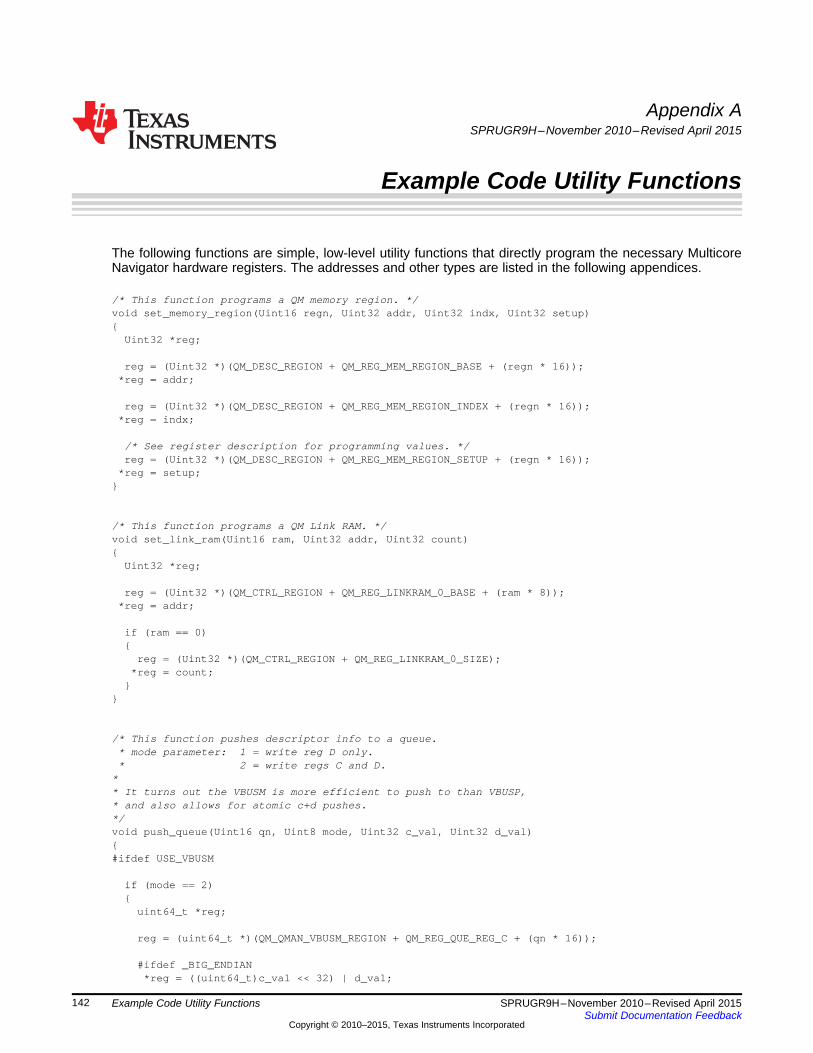
Appendix ASPRUGR9H–November 2010–Revised April 2015
Example Code Utility Functions
The following functions are simple, low-level utility functions that directly program the necessary MulticoreNavigator hardware registers. The addresses and other types are listed in the following appendices.
/* This function programs a QM memory region. */void set_memory_region(Uint16 regn, Uint32 addr, Uint32 indx, Uint32 setup){
Uint32 *reg;
reg = (Uint32 *)(QM_DESC_REGION + QM_REG_MEM_REGION_BASE + (regn * 16));*reg = addr;
reg = (Uint32 *)(QM_DESC_REGION + QM_REG_MEM_REGION_INDEX + (regn * 16));*reg = indx;
/* See register description for programming values. */reg = (Uint32 *)(QM_DESC_REGION + QM_REG_MEM_REGION_SETUP + (regn * 16));
*reg = setup;}
/* This function programs a QM Link RAM. */void set_link_ram(Uint16 ram, Uint32 addr, Uint32 count){
Uint32 *reg;
reg = (Uint32 *)(QM_CTRL_REGION + QM_REG_LINKRAM_0_BASE + (ram * 8));*reg = addr;
if (ram == 0){
reg = (Uint32 *)(QM_CTRL_REGION + QM_REG_LINKRAM_0_SIZE);*reg = count;
}}
/* This function pushes descriptor info to a queue.* mode parameter: 1 = write reg D only.* 2 = write regs C and D.
** It turns out the VBUSM is more efficient to push to than VBUSP,* and also allows for atomic c+d pushes.*/void push_queue(Uint16 qn, Uint8 mode, Uint32 c_val, Uint32 d_val){#ifdef USE_VBUSM
if (mode == 2){
uint64_t *reg;
reg = (uint64_t *)(QM_QMAN_VBUSM_REGION + QM_REG_QUE_REG_C + (qn * 16));
#ifdef _BIG_ENDIAN*reg = ((uint64_t)c_val << 32) | d_val;
142 Example Code Utility Functions SPRUGR9H–November 2010–Revised April 2015Submit Documentation Feedback
Copyright © 2010–2015, Texas Instruments Incorporated
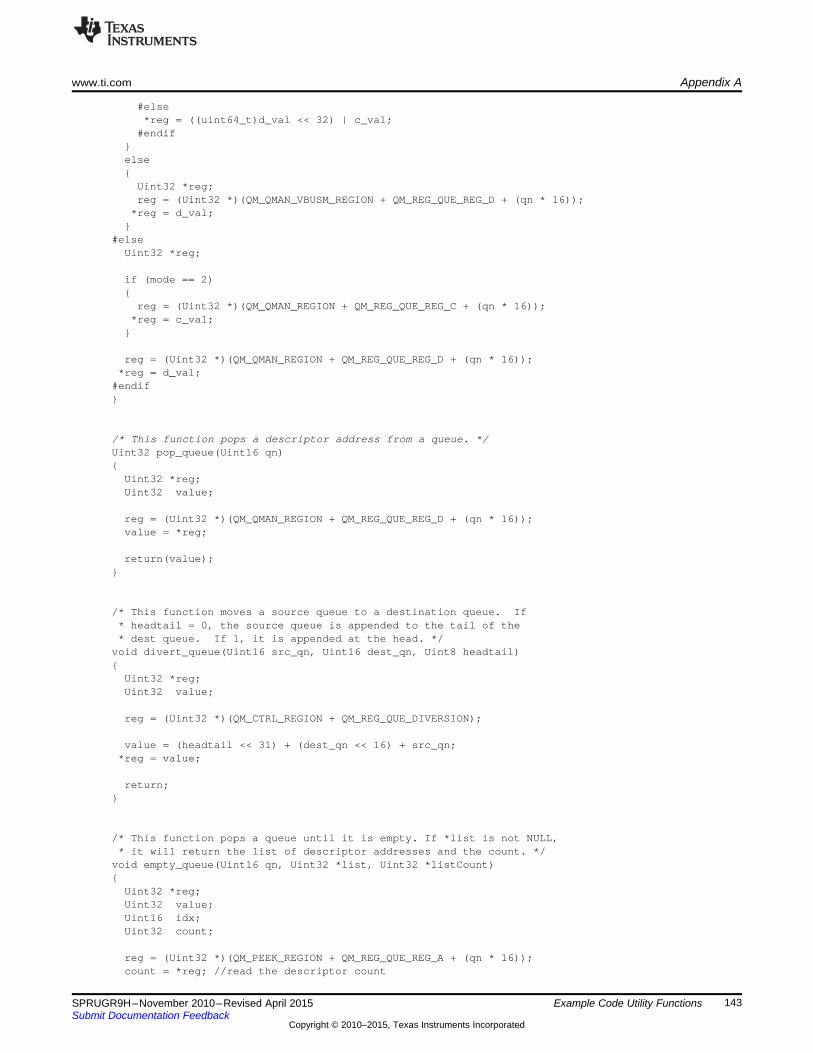
www.ti.com Appendix A
#else*reg = ((uint64_t)d_val << 32) | c_val;
#endif}else{
Uint32 *reg;reg = (Uint32 *)(QM_QMAN_VBUSM_REGION + QM_REG_QUE_REG_D + (qn * 16));
*reg = d_val;}
#elseUint32 *reg;
if (mode == 2){
reg = (Uint32 *)(QM_QMAN_REGION + QM_REG_QUE_REG_C + (qn * 16));*reg = c_val;
}
reg = (Uint32 *)(QM_QMAN_REGION + QM_REG_QUE_REG_D + (qn * 16));*reg = d_val;
#endif}
/* This function pops a descriptor address from a queue. */Uint32 pop_queue(Uint16 qn){
Uint32 *reg;Uint32 value;
reg = (Uint32 *)(QM_QMAN_REGION + QM_REG_QUE_REG_D + (qn * 16));value = *reg;
return(value);}
/* This function moves a source queue to a destination queue. If* headtail = 0, the source queue is appended to the tail of the* dest queue. If 1, it is appended at the head. */
void divert_queue(Uint16 src_qn, Uint16 dest_qn, Uint8 headtail){
Uint32 *reg;Uint32 value;
reg = (Uint32 *)(QM_CTRL_REGION + QM_REG_QUE_DIVERSION);
value = (headtail << 31) + (dest_qn << 16) + src_qn;*reg = value;
return;}
/* This function pops a queue until it is empty. If *list is not NULL,* it will return the list of descriptor addresses and the count. */
void empty_queue(Uint16 qn, Uint32 *list, Uint32 *listCount){
Uint32 *reg;Uint32 value;Uint16 idx;Uint32 count;
reg = (Uint32 *)(QM_PEEK_REGION + QM_REG_QUE_REG_A + (qn * 16));count = *reg; //read the descriptor count
143SPRUGR9H–November 2010–Revised April 2015 Example Code Utility FunctionsSubmit Documentation Feedback
Copyright © 2010–2015, Texas Instruments Incorporated
Appendix A www.ti.com
*listCount = count;
reg = (Uint32 *)(QM_QMAN_REGION + QM_REG_QUE_REG_D + (qn * 16));
for (idx = 0; idx < count; idx ++){
value = *reg;if (list != NULL){
list[idx] = value;}
}}
/* This function returns the byte count of a queue. */Uint32 get_byte_count(Uint16 qn){
Uint32 *reg;Uint32 count;
reg = (Uint32 *)(QM_PEEK_REGION + QM_REG_QUE_REG_B + (qn * 16));count = *reg;
return(count);}
/* This function returns the descriptor count of a queue. */Uint32 get_descriptor_count(Uint16 qn){
Uint32 *reg;Uint32 count;
reg = (Uint32 *)(QM_PEEK_REGION + QM_REG_QUE_REG_A + (qn * 16));count = *reg;
return(count);}
/* This function sets a queue threshold for queue monitoring purposes. */void set_queue_threshold(Uint16 qn, Uint32 value){
Uint32 *reg;
reg = (Uint32 *)(QM_PEEK_REGION + QM_REG_QUE_STATUS_REG_D + (qn * 16));*reg = value;
}
/* This function programs a Hi or Lo Accumulator channel. */void program_accumulator(Uint16 pdsp, Qmss_AccCmd *cmd){
Uint16 idx;Uint32 *tmplist;Uint32 *reg;
if (pdsp == 1)reg = (Uint32 *)(PDSP1_CMD_REGION + 4*4); //point to last word
elsereg = (Uint32 *)(PDSP2_CMD_REGION + 4*4); //point to last word
tmplist = ((uint32_t *) cmd) + 4; //write first word last
for (idx = 0; idx < 5; idx ++){
*reg-- = *tmplist--;
144 Example Code Utility Functions SPRUGR9H–November 2010–Revised April 2015Submit Documentation Feedback
Copyright © 2010–2015, Texas Instruments Incorporated

www.ti.com Appendix A
}
/* wait for the command byte to clear. */reg++;
do{
result = (*reg & 0x0000ff00) >> 8;} while (result != 0);
}
/* This function disables a Hi or Lo Accumulator program. */void disable_accumulator(Uint16 pdsp, Uint16 channel){
Uint16 idx;Uint32 *tmplist;Uint32 *reg;Qmss_AccCmd cmd;
memset(&cmd, 0, sizeof(Qmss_AccCmd));cmd.channel = channel;cmd.command = QMSS_ACC_CMD_DISABLE;
if (pdsp == 1)reg = (Uint32 *)(PDSP1_CMD_REGION + 4*4); //point to last word
elsereg = (Uint32 *)(PDSP2_CMD_REGION + 4*4); //point to last word
tmplist = ((uint32_t *) &cmd) + 4; //write first word last
for (idx = 0; idx < 5; idx ++){
*reg-- = *tmplist--;}
}
/* This function writes a new value to a PDSP's firmware* Time is specified in usec, then converted to the hardware* expect value assuming a 350Mhz QMSS sub-system clock. */
void set_firmware_timer(Uint16 pdsp, Uint16 time){
Uint16 idx;Uint32 *tmplist;Uint32 *reg;Qmss_AccCmd cmd;
memset(&cmd, 0, sizeof(Qmss_AccCmd));cmd.queue_mask = (time * 175); //convert usec to hw valcmd.command = QMSS_ACC_CMD_TIMER;
if (pdsp == 1)reg = (Uint32 *)(PDSP1_CMD_REGION + 4); //point to 2nd word
elsereg = (Uint32 *)(PDSP2_CMD_REGION + 4); //point to 2nd word
tmplist = ((uint32_t *) &cmd) + 1; //write 2nd word last
*reg-- = *tmplist--;*reg = *tmplist;
}
/* This function programs base addresses for the four logical* queue managers that a PKTDMA may setup. Use a value of 0xffff* if you don't want to set value into QM base addr reg. N. */
145SPRUGR9H–November 2010–Revised April 2015 Example Code Utility FunctionsSubmit Documentation Feedback
Copyright © 2010–2015, Texas Instruments Incorporated

Appendix A www.ti.com
void config_pktdma_qm(Uint32 base, Uint16 *physical_qnum){
Uint16 idx;Uint32 qm_base;Uint32 *reg;
for (idx = 0; idx < 4; idx ++){
if (physical_qnum[idx] != 0xffff){
qm_base = QM_QMAN_VBUSM_REGION + (physical_qnum[idx] * 16);
reg = (Uint32 *)(base + PKTDMA_REG_QM0_BASE_ADDR + (idx * 4));*reg = qm_base;
}}
}
/* This function enables/disables internal loopback mode for a pktDMA.* By default, it should be enabled for QMSS, disabled for all others. */
void config_pktdma_loopback(Uint32 base, Uint8 enable){
Uint32 *reg;
reg = (Uint32 *)(base + PKTDMA_REG_EMULATION_CTRL);
if (enable)*reg = 0x80000000;
else*reg = 0x0;
}
/* This function sets the packet retry timeout.* A value of 0 disables the retry feature. */
void config_pktdma_retry_timeout(Uint32 base, Uint16 timeout){
Uint32 *reg;
Uint32 val;
reg = (Uint32 *)(base + PKTDMA_REG_PERFORMANCE_CTRL);
val = *reg & 0xFFFF0000;
*reg = val | timeout;}/* This function disables a TX DMA channel, then configures it. */void config_tx_chan(Uint32 base, Uint16 chan, Uint32 return_q){
Uint32 *reg;
reg = (Uint32 *)(base + PKTDMA_REG_TX_CHAN_CFG_A + (chan * 32));*reg = 0; //disable the channel
reg = (Uint32 *)(base + PKTDMA_REG_TX_CHAN_CFG_B + (chan * 32));*reg = return_q;
}
/* This function configures priority of a TX DMA channel */void config_tx_sched(Uint32 base, Uint16 chan, Uint32 priority){
Uint32 *reg;
reg = (Uint32 *)(base + PKTDMA_REG_TX_SCHED_CHAN_CFG + (chan * 4));*reg = priority;
}
146 Example Code Utility Functions SPRUGR9H–November 2010–Revised April 2015Submit Documentation Feedback
Copyright © 2010–2015, Texas Instruments Incorporated
www.ti.com Appendix A
/* This function configures an RX DMA channel flow. */void config_rx_flow(Uint32 base, Uint16 flow,
Uint32 a, Uint32 b, Uint32 c, Uint32 d,Uint32 e, Uint32 f, Uint32 g, Uint32 h)
{Uint32 *reg;
reg = (Uint32 *)(base + PKTDMA_REG_RX_FLOW_CFG_A + (flow * 32));*reg = a;
reg = (Uint32 *)(base + PKTDMA_REG_RX_FLOW_CFG_B + (flow * 32));*reg = b;
reg = (Uint32 *)(base + PKTDMA_REG_RX_FLOW_CFG_C + (flow * 32));*reg = c;
reg = (Uint32 *)(base + PKTDMA_REG_RX_FLOW_CFG_D + (flow * 32));*reg = d;
reg = (Uint32 *)(base + PKTDMA_REG_RX_FLOW_CFG_E + (flow * 32));*reg = e;
reg = (Uint32 *)(base + PKTDMA_REG_RX_FLOW_CFG_F + (flow * 32));*reg = f;
reg = (Uint32 *)(base + PKTDMA_REG_RX_FLOW_CFG_G + (flow * 32));*reg = g;
reg = (Uint32 *)(base + PKTDMA_REG_RX_FLOW_CFG_H + (flow * 32));*reg = h;
}
/* This function writes an RX DMA channel's enable register. */void enable_rx_chan(Uint32 base, Uint16 chan, Uint32 value){
Uint32 *reg;
reg = (Uint32 *)(base + PKTDMA_REG_RX_CHAN_CFG_A + (chan * 32));*reg = value;
}
/* This function writes a TX DMA channel's enable register. */void enable_tx_chan(Uint32 base, Uint16 chan, Uint32 value){
Uint32 *reg; reg = (Uint32 *)(base + PKTDMA_REG_TX_CHAN_CFG_A + (chan * 32));*reg = value;
}
/* This function reads a QMSS INTD Status Register.* group parameter: 0 = high priority interrupts.* 1 = low priority interrupts.* 4 = PKTDMA starvation interrupts.** If the chan parameter = 0xffffffff, the entire register contents* are returned. Otherwise, chan is expected to be a channel number,* and the return value will be a 0 or 1 for that channel's status.*/
Uint32 read_status(Uint16 group, Uint32 chan){
Uint32 *reg;Uint32 value;Uint32 mask;
reg = (Uint32 *)(QM_INTD_REGION + QM_REG_INTD_STATUS + (group * 4));value = *reg;
147SPRUGR9H–November 2010–Revised April 2015 Example Code Utility FunctionsSubmit Documentation Feedback
Copyright © 2010–2015, Texas Instruments Incorporated

Appendix A www.ti.com
if (chan != 0xffffffff){
mask = 1 << (chan & 0x001f);if ((value & mask) == 0)
value = 0;else
value = 1;}
return(value);}
/* This function writes a QMSS INTD Status Register.* group parameter: 0 = high priority interrupts.* 1 = low priority interrupts.* 4 = PKTDMA starvation interrupts.*/
void set_status(Uint16 group, Uint32 chan){
Uint32 *reg;Uint32 value;Uint32 mask;
reg = (Uint32 *)(QM_INTD_REGION + QM_REG_INTD_STATUS + (group * 4));value = *reg;
mask = 1 << (chan & 0x001f);value |= mask;
*reg = value;}
/* This function writes a QMSS INTD Status Clear Register.* group parameter: 0 = high priority interrupts.* 1 = low priority interrupts.* 4 = PKTDMA starvation interrupts.*/
void clear_status(Uint16 group, Uint32 chan){
Uint32 *reg;Uint32 value;Uint32 mask;
reg = (Uint32 *)(QM_INTD_REGION + QM_REG_INTD_STATUS_CLEAR + (group * 4));value = *reg;
mask = 1 << (chan & 0x001f);value |= mask;
*reg = value;}
/* This function reads a QMSS INTD Int Count Register.* Reading has no effect on the register.* "intnum" is: 0..31 for High Pri interrupts* 32..47 for Low Pri interrupts* 48..49 for PKTDMA Starvation interrupts*/
Uint32 read_intcount(Uint16 intnum){
Uint32 *reg;Uint32 value;
148 Example Code Utility Functions SPRUGR9H–November 2010–Revised April 2015Submit Documentation Feedback
Copyright © 2010–2015, Texas Instruments Incorporated
www.ti.com Appendix A
reg = (Uint32 *)(QM_INTD_REGION + QM_REG_INTD_INT_COUNT + (intnum * 4));value = *reg;
return(value);}
/* This function reads a QMSS INTD Int Count Register.* Writing will cause the written value to be subtracted from the register.* "intnum" is: 0..31 for High Pri interrupts* 32..47 for Low Pri interrupts* 48..49 for PKTDMA Starvation interrupts*/
void write_intcount(Uint16 intnum, Uint32 val){
Uint32 *reg;
reg = (Uint32 *)(QM_INTD_REGION + QM_REG_INTD_INT_COUNT + (intnum * 4));*reg = val;
}
/* This function writes a QMSS INTD EOI Register. Values to write are:0 or 1: PKTDMA starvation interrupts,2 to 33: High Pri interrupts,
34 to 49: Low Pri interrupts.* Writing one of these values will clear the corresponding interrupt.*/
void write_eoi(Uint32 val){
Uint32 *reg;
reg = (Uint32 *)(QM_INTD_REGION + QM_REG_INTD_EOI);*reg = val;
}
/* This function writes a QMSS PDSP Control Register. */void pdsp_control(Uint16 pdsp, Uint32 val){
Uint32 *reg;
if (pdsp == 1)reg = (Uint32 *)(PDSP1_REG_REGION + QM_REG_PDSP_CONTROL);
elsereg = (Uint32 *)(PDSP2_REG_REGION + QM_REG_PDSP_CONTROL);
*reg = val;}
/* This function enables QMSS PDSP n. */void pdsp_enable(Uint16 pdsp){
Uint32 *reg;Uint32 tmp;
if (pdsp == 1)reg = (Uint32 *)(PDSP1_REG_REGION + QM_REG_PDSP_CONTROL);
elsereg = (Uint32 *)(PDSP2_REG_REGION + QM_REG_PDSP_CONTROL);
tmp = *reg;tmp |= 0x02;
*reg = tmp;
149SPRUGR9H–November 2010–Revised April 2015 Example Code Utility FunctionsSubmit Documentation Feedback
Copyright © 2010–2015, Texas Instruments Incorporated

Appendix A www.ti.com
}
/* This function disables QMSS PDSP n. */void pdsp_disable(Uint16 pdsp){
Uint32 *reg;Uint32 tmp;
if (pdsp == 1)reg = (Uint32 *)(PDSP1_REG_REGION + QM_REG_PDSP_CONTROL);
elsereg = (Uint32 *)(PDSP2_REG_REGION + QM_REG_PDSP_CONTROL);
tmp = *reg;tmp &= 0xfffffffd;
*reg = tmp;}
/* This function returns true if QMSS PDSP n is running. */Uint8 pdsp_running(Uint16 pdsp){
Uint32 *reg;
if (pdsp == 1)reg = (Uint32 *)(PDSP1_REG_REGION + QM_REG_PDSP_CONTROL);
elsereg = (Uint32 *)(PDSP2_REG_REGION + QM_REG_PDSP_CONTROL);
return(*reg & 0x00008000);}
/* This function controls the PDSP to load firmware to it. */void pdsp_download_firmware(Uint16 pdsp, Uint8 *code, Uint32 size){
Uint16 idx;Uint32 value;Uint32 *reg;
/* Reset PDSP 1 */pdsp_disable(pdsp);
/* Confirm PDSP has halted */do{
value = pdsp_running(pdsp);} while (value == 1);
/* Download the firmware */if (pdsp == 1)
memcpy ((void *)PDSP1_IRAM_REGION, code, size);else
memcpy ((void *)PDSP2_IRAM_REGION, code, size);
/* Use the command register to sync the PDSP */if (pdsp == 1)
reg = (Uint32 *)(PDSP1_CMD_REGION);else
reg = (Uint32 *)(PDSP2_CMD_REGION);*reg = 0xffffffff;
/* Wait to the memory write to land */for (idx = 0; idx < 20000; idx++){
150 Example Code Utility Functions SPRUGR9H–November 2010–Revised April 2015Submit Documentation Feedback
Copyright © 2010–2015, Texas Instruments Incorporated

www.ti.com Appendix A
value = *reg;if (value == 0xffffffff) break;
}
/* Reset program counter to zero, and clear Soft Reset bit. */if (pdsp == 1)
reg = (Uint32 *)(PDSP1_REG_REGION + QM_REG_PDSP_CONTROL);else
reg = (Uint32 *)(PDSP2_REG_REGION + QM_REG_PDSP_CONTROL);
value = *reg;*reg = value & 0x0000fffe; //PC reset is in upper 16 bits, soft reset in bit 0
/* Enable the PDSP */pdsp_enable(pdsp);
/* Wait for the command register to clear */if (pdsp == 1)
reg = (Uint32 *)(PDSP1_CMD_REGION);else
reg = (Uint32 *)(PDSP2_CMD_REGION);do{
value = *reg;} while (value != 0);
}
151SPRUGR9H–November 2010–Revised April 2015 Example Code Utility FunctionsSubmit Documentation Feedback
Copyright © 2010–2015, Texas Instruments Incorporated

Appendix A www.ti.com
152 Example Code Utility Functions SPRUGR9H–November 2010–Revised April 2015Submit Documentation Feedback
Copyright © 2010–2015, Texas Instruments Incorporated
Appendix BSPRUGR9H–November 2010–Revised April 2015
Example Code Types
The following type definitions are referenced by the programming examples above. For Big Endianapplications, they should be compiled with _BIG_ENDIAN defined.
//Define the Accumulator Command Interface Structure#ifdef _BIG_ENDIANtypedef struct{
uint32_t retrn_code:8; //0=idle, 1=success, 2-6=erroruint32_t un1:8;uint32_t command:8; //0x80=disable, 0x81=enable, 0=firmware responseuint32_t channel:8; //0 to 47 or 0 to 15
uint32_t queue_mask; //(multi-mode only) bit 0=qm_index queue
uint32_t list_address; //address of Host ping-pong buffer
uint32_t max_entries:16;//max entries per listuint32_t qm_index:16; //qnum to monitor (multiple of 32 for multimode)
uint32_t un2:8;uint32_t cfg_un:2;uint32_t cfg_multi_q:1; //0=single queue mode, 1=multi queue modeuint32_t cfg_list_mode:1;//0=NULL terminate, 1=entry count modeuint32_t cfg_list_size:2;//0="D" Reg, 1="C+D" regs, 2="A+B+C+D"uint32_t cfg_int_delay:2;//0=none, 1=last int, 2=1st new, 3=last newuint32_t timer_count:16;//number of 25us timer ticks to delay int
} Qmss_AccCmd;#elsetypedef struct{
uint32_t channel:8; //0 to 47 or 0 to 15uint32_t command:8; //0x80=disable, 0x81=enable, 0=firmware responseuint32_t un1:8;uint32_t retrn_code:8; //0=idle, 1=success, 2-6=error
uint32_t queue_mask; //(multi-mode only) bit 0=qm_index queue
uint32_t list_address; //address of Host ping-pong buffer
uint32_t qm_index:16; //qnum to monitor (multiple of 32 for multimode)uint32_t max_entries:16;//max entries per list
uint32_t timer_count:16;//number of 25us timer ticks to delay intuint32_t cfg_int_delay:2;//0=none, 1=last int, 2=1st new, 3=last newuint32_t cfg_list_size:2;//0="D" Reg, 1="C+D" regs, 2="A+B+C+D"uint32_t cfg_list_mode:1;//0=NULL terminate, 1=entry count modeuint32_t cfg_multi_q:1; //0=single queue mode, 1=multi queue modeuint32_t cfg_un:2;uint32_t un2:8;
} Qmss_AccCmd;#endif
/*******************************************************************/
153SPRUGR9H–November 2010–Revised April 2015 Example Code TypesSubmit Documentation Feedback
Copyright © 2010–2015, Texas Instruments Incorporated

Appendix B www.ti.com
/* Define the bit and word layouts for the Host Packet Descriptor. *//* For a Host Packet, this is used for the first descriptor only. *//*******************************************************************/#ifdef _BIG_ENDIANtypedef struct{
/* word 0 */uint32_t type_id : 2; //always 0x0 (Host Packet ID)uint32_t packet_type : 5;uint32_t reserved_w0 : 2;uint32_t ps_reg_loc : 1; //0=PS words in desc, 1=PS words in SOP buffuint32_t packet_length : 22; //in bytes (4M - 1 max)
/* word 1 */uint32_t src_tag_hi : 8;uint32_t src_tag_lo : 8;uint32_t dest_tag_hi : 8;uint32_t dest_tag_lo : 8;
/* word 2 */uint32_t epib : 1; //1=extended packet info block is presentuint32_t reserved_w2 : 1;uint32_t psv_word_count : 6; //number of 32-bit PS data wordsuint32_t err_flags : 4;uint32_t ps_flags : 4;uint32_t return_policy : 1; //0=linked packet goes to pkt_return_qnum,
//1=each descriptor goes to pkt_return_qnumuint32_t ret_push_policy : 1; //0=return to queue tail, 1=queue headuint32_t pkt_return_qmgr : 2;uint32_t pkt_return_qnum : 12;
/* word 3 */uint32_t reserved_w3 : 10;uint32_t buffer_len : 22;
/* word 4 */uint32_t buffer_ptr;
/* word 5 */uint32_t next_desc_ptr;
/* word 6 */uint32_t orig_buff0_pool : 4;uint32_t orig_buff0_refc : 6;uint32_t orig_buff0_len : 22;
/* word 7 */uint32_t orig_buff0_ptr;
} MNAV_HostPacketDescriptor;#elsetypedef struct{
/* word 0 */uint32_t packet_length : 22; //in bytes (4M - 1 max)uint32_t ps_reg_loc : 1; //0=PS words in desc, 1=PS words in SOP buffuint32_t reserved_w0 : 2;uint32_t packet_type : 5;uint32_t type_id : 2; //always 0x0 (Host Packet ID)
/* word 1 */uint32_t dest_tag_lo : 8;uint32_t dest_tag_hi : 8;uint32_t src_tag_lo : 8;uint32_t src_tag_hi : 8;
154 Example Code Types SPRUGR9H–November 2010–Revised April 2015Submit Documentation Feedback
Copyright © 2010–2015, Texas Instruments Incorporated

www.ti.com Appendix B
/* word 2 */uint32_t pkt_return_qnum : 12;uint32_t pkt_return_qmgr : 2;uint32_t ret_push_policy : 1; //0=return to queue tail, 1=queue headuint32_t return_policy : 1; //0=linked packet goes to pkt_return_qnum,
//1=each descriptor goes to pkt_return_qnumuint32_t ps_flags : 4;uint32_t err_flags : 4;uint32_t psv_word_count : 6; //number of 32-bit PS data wordsuint32_t reserved_w2 : 1;uint32_t epib : 1; //1=extended packet info block is present
/* word 3 */uint32_t buffer_len : 22;uint32_t reserved_w3 : 10;
/* word 4 */uint32_t buffer_ptr;
/* word 5 */uint32_t next_desc_ptr;
/* word 6 */uint32_t orig_buff0_len : 22;uint32_t orig_buff0_refc : 6;uint32_t orig_buff0_pool : 4;
/* word 7 */uint32_t orig_buff0_ptr;
} MNAV_HostPacketDescriptor;#endif
#define MNAV_HOST_PACKET_SIZE sizeof(MNAV_HostPacketDescriptor)
/*******************************************************************//* Define the bit and word layouts for the Host Buffer Descriptor. *//* For a Host Packet, this will used for secondary descriptors. *//*******************************************************************/#ifdef _BIG_ENDIANtypedef struct{
/* word 0 */uint32_t reserved_w0;/* word 1 */uint32_t reserved_w1;
/* word 2 */uint32_t reserved_w2 : 17;uint32_t ret_push_policy : 1; //0=return to queue tail, 1=queue headuint32_t pkt_return_qmgr : 2;uint32_t pkt_return_qnum : 12;
/* word 3 */uint32_t reserved_w3 : 10;uint32_t buffer_len : 22;
/* word 4 */uint32_t buffer_ptr;
/* word 5 */uint32_t next_desc_ptr;
/* word 6 */
155SPRUGR9H–November 2010–Revised April 2015 Example Code TypesSubmit Documentation Feedback
Copyright © 2010–2015, Texas Instruments Incorporated

Appendix B www.ti.com
uint32_t orig_buff0_pool : 4;uint32_t orig_buff0_refc : 6;uint32_t orig_buff0_len : 22;
/* word 7 */uint32_t orig_buff0_ptr;
} MNAV_HostBufferDescriptor;#elsetypedef struct{
/* word 0 */uint32_t reserved_w0;/* word 1 */uint32_t reserved_w1;
/* word 2 */uint32_t pkt_return_qnum : 12;uint32_t pkt_return_qmgr : 2;uint32_t ret_push_policy : 1; //0=return to queue tail, 1=queue headuint32_t reserved_w2 : 17;
/* word 3 */uint32_t buffer_len : 22;uint32_t reserved_w3 : 10;
/* word 4 */uint32_t buffer_ptr;
/* word 5 */uint32_t next_desc_ptr;
/* word 6 */uint32_t orig_buff0_len : 22;uint32_t orig_buff0_refc : 6;uint32_t orig_buff0_pool : 4;
/* word 7 */uint32_t orig_buff0_ptr;
} MNAV_HostBufferDescriptor;#endif
// Host Buffer packet size is always the same as Host Packet size
/*********************************************************************//* Define the bit and word layouts for the Monolithic Pkt Descriptor.*//*********************************************************************/#ifdef _BIG_ENDIANtypedef struct{
/* word 0 */uint32_t type_id : 2; //always 0x2 (Monolithic Packet ID)uint32_t packet_type : 5;uint32_t data_offset : 9;uint32_t packet_length : 16; //in bytes (65535 max)
/* word 1 */uint32_t src_tag_hi : 8;uint32_t src_tag_lo : 8;uint32_t dest_tag_hi : 8;uint32_t dest_tag_lo : 8;
/* word 2 */uint32_t epib : 1; //1=extended packet info block is present
156 Example Code Types SPRUGR9H–November 2010–Revised April 2015Submit Documentation Feedback
Copyright © 2010–2015, Texas Instruments Incorporated
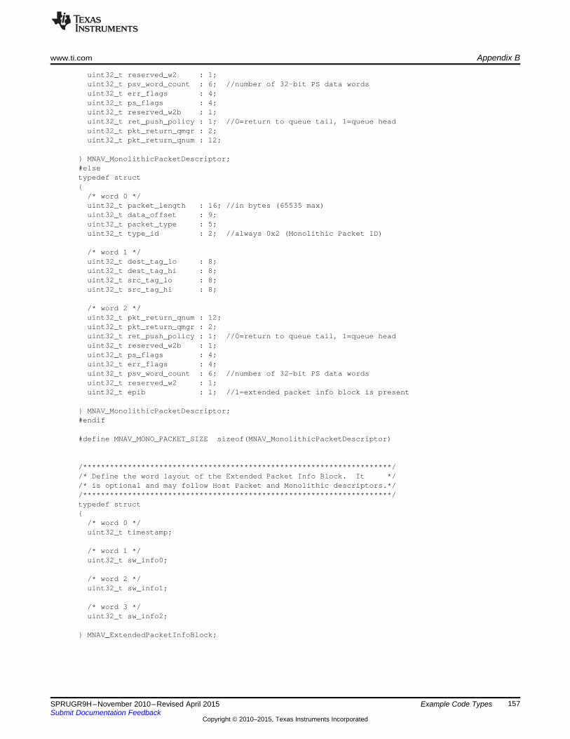
www.ti.com Appendix B
uint32_t reserved_w2 : 1;uint32_t psv_word_count : 6; //number of 32-bit PS data wordsuint32_t err_flags : 4;uint32_t ps_flags : 4;uint32_t reserved_w2b : 1;uint32_t ret_push_policy : 1; //0=return to queue tail, 1=queue headuint32_t pkt_return_qmgr : 2;uint32_t pkt_return_qnum : 12;
} MNAV_MonolithicPacketDescriptor;#elsetypedef struct{
/* word 0 */uint32_t packet_length : 16; //in bytes (65535 max)uint32_t data_offset : 9;uint32_t packet_type : 5;uint32_t type_id : 2; //always 0x2 (Monolithic Packet ID)
/* word 1 */uint32_t dest_tag_lo : 8;uint32_t dest_tag_hi : 8;uint32_t src_tag_lo : 8;uint32_t src_tag_hi : 8;
/* word 2 */uint32_t pkt_return_qnum : 12;uint32_t pkt_return_qmgr : 2;uint32_t ret_push_policy : 1; //0=return to queue tail, 1=queue headuint32_t reserved_w2b : 1;uint32_t ps_flags : 4;uint32_t err_flags : 4;uint32_t psv_word_count : 6; //number of 32-bit PS data wordsuint32_t reserved_w2 : 1;uint32_t epib : 1; //1=extended packet info block is present
} MNAV_MonolithicPacketDescriptor;#endif
#define MNAV_MONO_PACKET_SIZE sizeof(MNAV_MonolithicPacketDescriptor)
/*********************************************************************//* Define the word layout of the Extended Packet Info Block. It *//* is optional and may follow Host Packet and Monolithic descriptors.*//*********************************************************************/typedef struct{
/* word 0 */uint32_t timestamp;
/* word 1 */uint32_t sw_info0;
/* word 2 */uint32_t sw_info1;
/* word 3 */uint32_t sw_info2;
} MNAV_ExtendedPacketInfoBlock;
157SPRUGR9H–November 2010–Revised April 2015 Example Code TypesSubmit Documentation Feedback
Copyright © 2010–2015, Texas Instruments Incorporated

Appendix B www.ti.com
158 Example Code Types SPRUGR9H–November 2010–Revised April 2015Submit Documentation Feedback
Copyright © 2010–2015, Texas Instruments Incorporated

Appendix CSPRUGR9H–November 2010–Revised April 2015
Example Code Addresses
These #defines are the values referenced by the programming examples in this document. A register’saddress is the combination of base_address + region_offset + register_offset + (instance_offset), whereinstance_offset is the copy of the desired register times the offset from one instance to the next (seeAppendix A for example of this).
C.1 KeyStone I Addresses:
#define QMSS_CFG_BASE (0x02a00000u)#define QMSS_VBUSM_BASE (0x34000000u)#define SRIO_CFG_BASE (0x02900000u)#define PASS_CFG_BASE (0x02000000u)#define FFTCA_CFG_BASE (0x021f0000u)#define FFTCB_CFG_BASE (0x021f4000u)#define AIF_CFG_BASE (0x01f00000u)
/* Define QMSS Register block regions. */#define QM_CTRL_REGION (QMSS_CFG_BASE + 0x00068000u)#define QM_DESC_REGION (QMSS_CFG_BASE + 0x0006a000u)#define QM_QMAN_REGION (QMSS_CFG_BASE + 0x00020000u)#define QM_QMAN_VBUSM_REGION (QMSS_VBUSM_BASE + 0x00020000u)#define QM_PEEK_REGION (QMSS_CFG_BASE + 0x00000000u)#define QM_LRAM_REGION ( + 0x00080000u)#define QM_INTD_REGION (QMSS_CFG_BASE + 0x000a0000u)#define QM_PROXY_REGION (QMSS_CFG_BASE + 0x00040000u)#define PDSP1_CMD_REGION (QMSS_CFG_BASE + 0x000b8000u)#define PDSP2_CMD_REGION (QMSS_CFG_BASE + 0x000bc000u)#define PDSP1_REG_REGION (QMSS_CFG_BASE + 0x0006E000u)#define PDSP2_REG_REGION (QMSS_CFG_BASE + 0x0006F000u)#define PDSP1_IRAM_REGION (QMSS_CFG_BASE + 0x00060000u)#define PDSP2_IRAM_REGION (QMSS_CFG_BASE + 0x00061000u)
/* Define QMSS PKTDMA Register block regions. */#define QMSS_PKTDMA_GBL_CFG_REGION (QMSS_CFG_BASE + 0x0006c000u)#define QMSS_PKTDMA_TX_CHAN_REGION (QMSS_CFG_BASE + 0x0006c400u)#define QMSS_PKTDMA_RX_CHAN_REGION (QMSS_CFG_BASE + 0x0006c800u)#define QMSS_PKTDMA_TX_SCHD_REGION (QMSS_CFG_BASE + 0x0006cc00u)#define QMSS_PKTDMA_RX_FLOW_REGION (QMSS_CFG_BASE + 0x0006d000u)
/* Define PASS PKTDMA Register block regions. */#define PASS_PKTDMA_GBL_CFG_REGION (PASS_CFG_BASE + 0x00004000u)#define PASS_PKTDMA_TX_CHAN_REGION (PASS_CFG_BASE + 0x00004400u)#define PASS_PKTDMA_RX_CHAN_REGION (PASS_CFG_BASE + 0x00004800u)#define PASS_PKTDMA_TX_SCHD_REGION (PASS_CFG_BASE + 0x00004c00u)#define PASS_PKTDMA_RX_FLOW_REGION (PASS_CFG_BASE + 0x00005000u)
/* Define SRIO PKTDMA Register block regions. */#define SRIO_PKTDMA_GBL_CFG_REGION (SRIO_CFG_BASE + 0x00001000u)#define SRIO_PKTDMA_TX_CHAN_REGION (SRIO_CFG_BASE + 0x00001400u)#define SRIO_PKTDMA_RX_CHAN_REGION (SRIO_CFG_BASE + 0x00001800u)#define SRIO_PKTDMA_TX_SCHD_REGION (SRIO_CFG_BASE + 0x00001c00u)#define SRIO_PKTDMA_RX_FLOW_REGION (SRIO_CFG_BASE + 0x00002000u)
/* Define FFTC A PKTDMA Register block regions. */#define FFTCA_PKTDMA_GBL_CFG_REGION (FFTCA_CFG_BASE + 0x00000200u)
159SPRUGR9H–November 2010–Revised April 2015 Example Code AddressesSubmit Documentation Feedback
Copyright © 2010–2015, Texas Instruments Incorporated
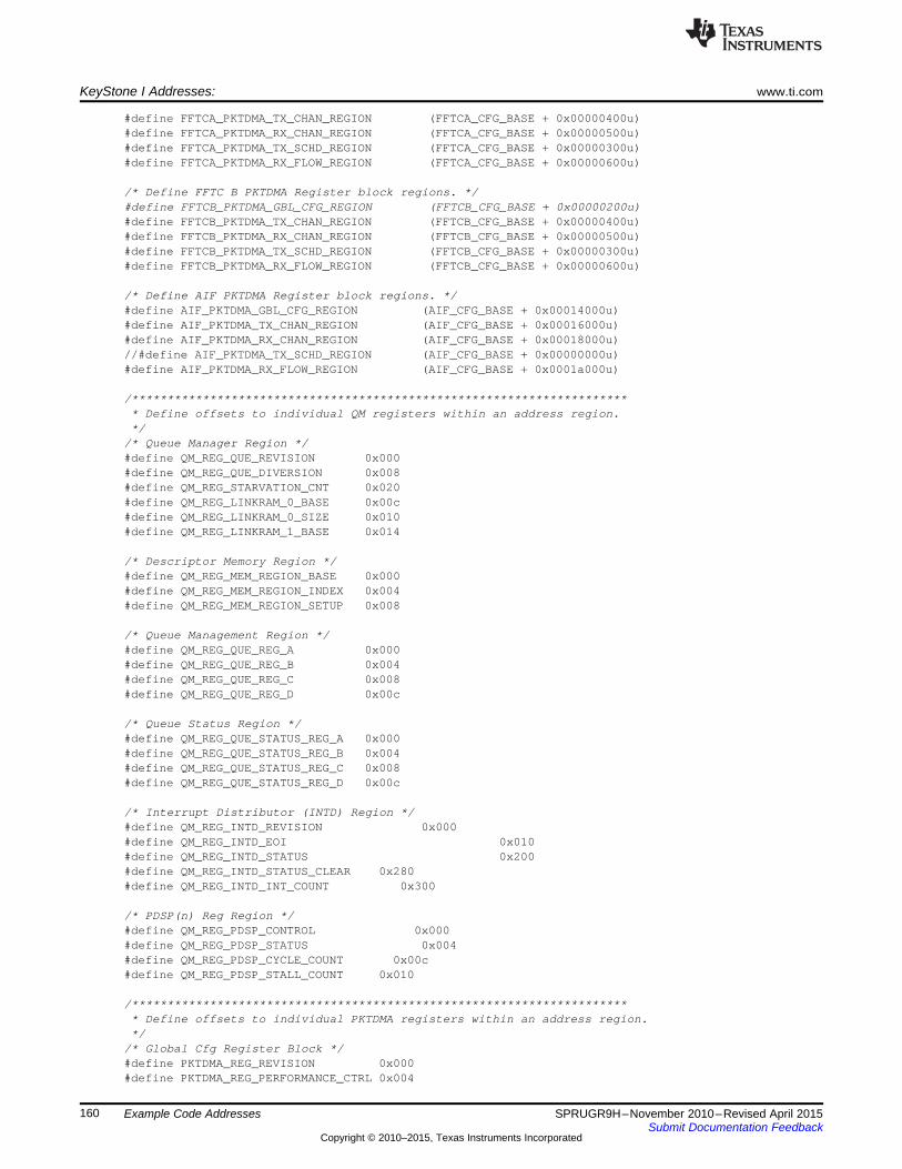
KeyStone I Addresses: www.ti.com
#define FFTCA_PKTDMA_TX_CHAN_REGION (FFTCA_CFG_BASE + 0x00000400u)#define FFTCA_PKTDMA_RX_CHAN_REGION (FFTCA_CFG_BASE + 0x00000500u)#define FFTCA_PKTDMA_TX_SCHD_REGION (FFTCA_CFG_BASE + 0x00000300u)#define FFTCA_PKTDMA_RX_FLOW_REGION (FFTCA_CFG_BASE + 0x00000600u)
/* Define FFTC B PKTDMA Register block regions. */#define FFTCB_PKTDMA_GBL_CFG_REGION (FFTCB_CFG_BASE + 0x00000200u)#define FFTCB_PKTDMA_TX_CHAN_REGION (FFTCB_CFG_BASE + 0x00000400u)#define FFTCB_PKTDMA_RX_CHAN_REGION (FFTCB_CFG_BASE + 0x00000500u)#define FFTCB_PKTDMA_TX_SCHD_REGION (FFTCB_CFG_BASE + 0x00000300u)#define FFTCB_PKTDMA_RX_FLOW_REGION (FFTCB_CFG_BASE + 0x00000600u)
/* Define AIF PKTDMA Register block regions. */#define AIF_PKTDMA_GBL_CFG_REGION (AIF_CFG_BASE + 0x00014000u)#define AIF_PKTDMA_TX_CHAN_REGION (AIF_CFG_BASE + 0x00016000u)#define AIF_PKTDMA_RX_CHAN_REGION (AIF_CFG_BASE + 0x00018000u)//#define AIF_PKTDMA_TX_SCHD_REGION (AIF_CFG_BASE + 0x00000000u)#define AIF_PKTDMA_RX_FLOW_REGION (AIF_CFG_BASE + 0x0001a000u)
/*********************************************************************** Define offsets to individual QM registers within an address region.*/
/* Queue Manager Region */#define QM_REG_QUE_REVISION 0x000#define QM_REG_QUE_DIVERSION 0x008#define QM_REG_STARVATION_CNT 0x020#define QM_REG_LINKRAM_0_BASE 0x00c#define QM_REG_LINKRAM_0_SIZE 0x010#define QM_REG_LINKRAM_1_BASE 0x014
/* Descriptor Memory Region */#define QM_REG_MEM_REGION_BASE 0x000#define QM_REG_MEM_REGION_INDEX 0x004#define QM_REG_MEM_REGION_SETUP 0x008
/* Queue Management Region */#define QM_REG_QUE_REG_A 0x000#define QM_REG_QUE_REG_B 0x004#define QM_REG_QUE_REG_C 0x008#define QM_REG_QUE_REG_D 0x00c
/* Queue Status Region */#define QM_REG_QUE_STATUS_REG_A 0x000#define QM_REG_QUE_STATUS_REG_B 0x004#define QM_REG_QUE_STATUS_REG_C 0x008#define QM_REG_QUE_STATUS_REG_D 0x00c
/* Interrupt Distributor (INTD) Region */#define QM_REG_INTD_REVISION 0x000#define QM_REG_INTD_EOI 0x010#define QM_REG_INTD_STATUS 0x200#define QM_REG_INTD_STATUS_CLEAR 0x280#define QM_REG_INTD_INT_COUNT 0x300
/* PDSP(n) Reg Region */#define QM_REG_PDSP_CONTROL 0x000#define QM_REG_PDSP_STATUS 0x004#define QM_REG_PDSP_CYCLE_COUNT 0x00c#define QM_REG_PDSP_STALL_COUNT 0x010
/*********************************************************************** Define offsets to individual PKTDMA registers within an address region.*/
/* Global Cfg Register Block */#define PKTDMA_REG_REVISION 0x000#define PKTDMA_REG_PERFORMANCE_CTRL 0x004
160 Example Code Addresses SPRUGR9H–November 2010–Revised April 2015Submit Documentation Feedback
Copyright © 2010–2015, Texas Instruments Incorporated
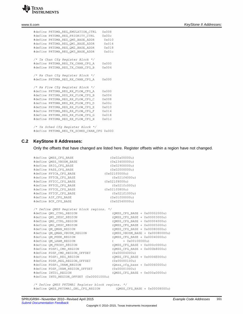
www.ti.com KeyStone II Addresses:
#define PKTDMA_REG_EMULATION_CTRL 0x008#define PKTDMA_REG_PRIORITY_CTRL 0x00c#define PKTDMA_REG_QM0_BASE_ADDR 0x010#define PKTDMA_REG_QM1_BASE_ADDR 0x014#define PKTDMA_REG_QM2_BASE_ADDR 0x018#define PKTDMA_REG_QM3_BASE_ADDR 0x01c
/* Tx Chan Cfg Register Block */#define PKTDMA_REG_TX_CHAN_CFG_A 0x000#define PKTDMA_REG_TX_CHAN_CFG_B 0x004
/* Rx Chan Cfg Register Block */#define PKTDMA_REG_RX_CHAN_CFG_A 0x000
/* Rx Flow Cfg Register Block */#define PKTDMA_REG_RX_FLOW_CFG_A 0x000#define PKTDMA_REG_RX_FLOW_CFG_B 0x004#define PKTDMA_REG_RX_FLOW_CFG_C 0x008#define PKTDMA_REG_RX_FLOW_CFG_D 0x00c#define PKTDMA_REG_RX_FLOW_CFG_E 0x010#define PKTDMA_REG_RX_FLOW_CFG_F 0x014#define PKTDMA_REG_RX_FLOW_CFG_G 0x018#define PKTDMA_REG_RX_FLOW_CFG_H 0x01c
/* Tx Sched Cfg Register Block */#define PKTDMA_REG_TX_SCHED_CHAN_CFG 0x000
C.2 KeyStone II Addresses:Only the offsets that have changed are listed here. Register offsets within a region have not changed.
#define QMSS_CFG_BASE (0x02a00000u)#define QMSS_VBUSM_BASE (0x23400000u)#define SRIO_CFG_BASE (0x02900000u)#define PASS_CFG_BASE (0x02000000u)#define FFTCA_CFG_BASE (0x021f0000u)#define FFTCB_CFG_BASE (0x021f4000u)#define FFTCC_CFG_BASE (0x021f8000u)#define FFTCD_CFG_BASE (0x021fc000u)#define FFTCE_CFG_BASE (0x021f0800u)#define FFTCF_CFG_BASE (0x021f1000u)#define AIF_CFG_BASE (0x01f00000u)#define BCP_CFG_BASE (0x02540000u)
/* Define QMSS Register block regions. */#define QM1_CTRL_REGION (QMSS_CFG_BASE + 0x00002000u)#define QM1_DESC_REGION (QMSS_CFG_BASE + 0x00003000u)#define QM2_CTRL_REGION (QMSS_CFG_BASE + 0x00004000u)#define QM2_DESC_REGION (QMSS_CFG_BASE + 0x00005000u)#define QM_QMAN_REGION (QMSS_CFG_BASE + 0x00080000u)#define QM_QMAN_VBUSM_REGION (QMSS_VBUSM_BASE + 0x00080000u)#define QM_PEEK_REGION (QMSS_CFG_BASE + 0x00040000u)#define QM_LRAM_REGION ( + 0x00100000u)#define QM_PROXY_REGION (QMSS_CFG_BASE + 0x000c0000u)#define PDSP1_CMD_REGION (QMSS_CFG_BASE + 0x000b8000u)#define PDSP_CMD_REGION_OFFSET (0x00004000u)#define PDSP1_REG_REGION (QMSS_CFG_BASE + 0x0006E000u)#define PDSP_REG_REGION_OFFSET (0x00000100u)#define PDSP1_IRAM_REGION (Qmss_cfg_base + 0x00060000u)#define PDSP_IRAM_REGION_OFFSET (0x00001000u)#define INTD1_REGION (QMSS_CFG_BASE + 0x000a0000u)#define INTD_REGION_OFFSET (0x00001000u)
/* Define QMSS PKTDMA1 Register block regions. */#define QMSS_PKTDMA1_GBL_CFG_REGION (QMSS_CFG_BASE + 0x00008000u)
161SPRUGR9H–November 2010–Revised April 2015 Example Code AddressesSubmit Documentation Feedback
Copyright © 2010–2015, Texas Instruments Incorporated

KeyStone II Addresses: www.ti.com
#define QMSS_PKTDMA1_TX_CHAN_REGION (QMSS_CFG_BASE + 0x00008400u)#define QMSS_PKTDMA1_RX_CHAN_REGION (QMSS_CFG_BASE + 0x00008800u)#define QMSS_PKTDMA1_TX_SCHD_REGION (QMSS_CFG_BASE + 0x00008c00u)#define QMSS_PKTDMA1_RX_FLOW_REGION (QMSS_CFG_BASE + 0x00009000u)
/* Define QMSS PKTDMA2 Register block regions. */#define QMSS_PKTDMA2_GBL_CFG_REGION (QMSS_CFG_BASE + 0x0000a000u)#define QMSS_PKTDMA2_TX_CHAN_REGION (QMSS_CFG_BASE + 0x0000a400u)#define QMSS_PKTDMA2_RX_CHAN_REGION (QMSS_CFG_BASE + 0x0000a800u)#define QMSS_PKTDMA2_TX_SCHD_REGION (QMSS_CFG_BASE + 0x0000ac00u)#define QMSS_PKTDMA2_RX_FLOW_REGION (QMSS_CFG_BASE + 0x0000b000u)
162 Example Code Addresses SPRUGR9H–November 2010–Revised April 2015Submit Documentation Feedback
Copyright © 2010–2015, Texas Instruments Incorporated

www.ti.com KeyStone II Addresses:
163SPRUGR9H–November 2010–Revised April 2015 Example Code AddressesSubmit Documentation Feedback
Copyright © 2010–2015, Texas Instruments Incorporated

Revision History www.ti.com
Revision History
Changes from October 1, 2014 to April 30, 2015 ............................................................................................................ Page
• Added Note to Descriptor Memory Setup Region section. ......................................................................... 50• Added Note to Quality of Service Firmware section................................................................................. 87
Revision History
Changes from F Revision (November 2010) to G Revision ........................................................................................... Page
• Updated Queue Types section. ........................................................................................................ 22• Added Queue Pend Queues section. ................................................................................................. 23• Updated Queue Diversion Register description...................................................................................... 44• Updated Caution. ........................................................................................................................ 57
NOTE: Page numbers for previous revisions may differ from page numbers in the current version.
164 Revision History SPRUGR9H–November 2010–Revised April 2015Submit Documentation Feedback
Copyright © 2010–2015, Texas Instruments Incorporated
IMPORTANT NOTICE
Texas Instruments Incorporated and its subsidiaries (TI) reserve the right to make corrections, enhancements, improvements and otherchanges to its semiconductor products and services per JESD46, latest issue, and to discontinue any product or service per JESD48, latestissue. Buyers should obtain the latest relevant information before placing orders and should verify that such information is current andcomplete. All semiconductor products (also referred to herein as “components”) are sold subject to TI’s terms and conditions of salesupplied at the time of order acknowledgment.TI warrants performance of its components to the specifications applicable at the time of sale, in accordance with the warranty in TI’s termsand conditions of sale of semiconductor products. Testing and other quality control techniques are used to the extent TI deems necessaryto support this warranty. Except where mandated by applicable law, testing of all parameters of each component is not necessarilyperformed.TI assumes no liability for applications assistance or the design of Buyers’ products. Buyers are responsible for their products andapplications using TI components. To minimize the risks associated with Buyers’ products and applications, Buyers should provideadequate design and operating safeguards.TI does not warrant or represent that any license, either express or implied, is granted under any patent right, copyright, mask work right, orother intellectual property right relating to any combination, machine, or process in which TI components or services are used. Informationpublished by TI regarding third-party products or services does not constitute a license to use such products or services or a warranty orendorsement thereof. Use of such information may require a license from a third party under the patents or other intellectual property of thethird party, or a license from TI under the patents or other intellectual property of TI.Reproduction of significant portions of TI information in TI data books or data sheets is permissible only if reproduction is without alterationand is accompanied by all associated warranties, conditions, limitations, and notices. TI is not responsible or liable for such altereddocumentation. Information of third parties may be subject to additional restrictions.Resale of TI components or services with statements different from or beyond the parameters stated by TI for that component or servicevoids all express and any implied warranties for the associated TI component or service and is an unfair and deceptive business practice.TI is not responsible or liable for any such statements.Buyer acknowledges and agrees that it is solely responsible for compliance with all legal, regulatory and safety-related requirementsconcerning its products, and any use of TI components in its applications, notwithstanding any applications-related information or supportthat may be provided by TI. Buyer represents and agrees that it has all the necessary expertise to create and implement safeguards whichanticipate dangerous consequences of failures, monitor failures and their consequences, lessen the likelihood of failures that might causeharm and take appropriate remedial actions. Buyer will fully indemnify TI and its representatives against any damages arising out of the useof any TI components in safety-critical applications.In some cases, TI components may be promoted specifically to facilitate safety-related applications. With such components, TI’s goal is tohelp enable customers to design and create their own end-product solutions that meet applicable functional safety standards andrequirements. Nonetheless, such components are subject to these terms.No TI components are authorized for use in FDA Class III (or similar life-critical medical equipment) unless authorized officers of the partieshave executed a special agreement specifically governing such use.Only those TI components which TI has specifically designated as military grade or “enhanced plastic” are designed and intended for use inmilitary/aerospace applications or environments. Buyer acknowledges and agrees that any military or aerospace use of TI componentswhich have not been so designated is solely at the Buyer's risk, and that Buyer is solely responsible for compliance with all legal andregulatory requirements in connection with such use.TI has specifically designated certain components as meeting ISO/TS16949 requirements, mainly for automotive use. In any case of use ofnon-designated products, TI will not be responsible for any failure to meet ISO/TS16949.
Products ApplicationsAudio www.ti.com/audio Automotive and Transportation www.ti.com/automotiveAmplifiers amplifier.ti.com Communications and Telecom www.ti.com/communicationsData Converters dataconverter.ti.com Computers and Peripherals www.ti.com/computersDLP® Products www.dlp.com Consumer Electronics www.ti.com/consumer-appsDSP dsp.ti.com Energy and Lighting www.ti.com/energyClocks and Timers www.ti.com/clocks Industrial www.ti.com/industrialInterface interface.ti.com Medical www.ti.com/medicalLogic logic.ti.com Security www.ti.com/securityPower Mgmt power.ti.com Space, Avionics and Defense www.ti.com/space-avionics-defenseMicrocontrollers microcontroller.ti.com Video and Imaging www.ti.com/videoRFID www.ti-rfid.comOMAP Applications Processors www.ti.com/omap TI E2E Community e2e.ti.comWireless Connectivity www.ti.com/wirelessconnectivity
Mailing Address: Texas Instruments, Post Office Box 655303, Dallas, Texas 75265Copyright © 2015, Texas Instruments Incorporated