key enhancements for power*tools forskmsupport.com/temp/ptw_6.5_enhancements.pdfkey enhancements for...
TRANSCRIPT

Key Enhancements for Power*Tools for Windows Version 6.5
TE C H N OL O G Y A T WO R K FO R Y O U
1. Added manufacturer specific selective coordination tables to the PTW library. Allows search for up-to-down and down-to-up selective coordination pairs. Filter for devices based on voltage, frame amps, interrupting amps, and selective level.
2. New Report Viewer user interface and format (.rp2) allows for image insertion along with enhanced text and picture editing and formatting. The Report Viewer includes saving to .doc, .txt, and .pdf formats.
3. Support for larger one-line drawing areas and navigation to sub-drawings and other PTW internal and external document types.
4. Nametag and Datablock orientations and default placement relative to the symbol body. 5. Support the creation of Legend tags (annotated poly-line symbols) on the one-line and report/
display Legends. 6. Option to report results based on the worst-case scenario in Arc Flash Evaluation. Expanded the
Arc Flash study option dialog for specialized calculation and efficiency. 7. Option to select user-defined levels of upstream mis-coordination checking in Arc Flash. 8. Added ability to customize the reporting fields and sorting orders in the Arc Flash spreadsheet
report. 9. Many additions to the Arc Flash PPE Table and Custom Labels including dynamic pictures for
protection equipments, multiple copies of labels to print for different locations, etc. 10. Added NESC 2007 standard option for incident energy and flash boundary determination. 11. New protective devices added and new quick search and query capability. Approximately 1400 new
devices have been added. Also includes Equipment Specific Arc Flash equations. 12. Ability to specify phase or neutral sensor location and to model differential, directional, summation,
and zone interlock devices within Captor and to shift the TCC accordingly. 13. Ability to model differential, directional, summation, and zone interlock devices in Arc Flash. 14. Device and TCC notes area can store links to other documents, including external files. 15. Ability to plot the entire range of fuse sizes simultaneously. Also added ability to plot Bus Damage
Curve, Capacitor Case Rapture Curve, Reduced Voltage Motor Starting Curve, Motor Asymmetrical Inrush, Transformer User-Define Inrush Curve/Points, etc.
16. Improved the multiple protection function interface to verify the functions to be plotted in the same TCC drawing. This includes the settings from the functions to be displayed in the one-line Datablock; the functions to be included in Equipment Evaluation; and the function types and sensor locations.
17. Variable Frequency Drive (VFD) model as a standard component type in PTW. Includes model regenerative and bypass modes.
18. New Thermal equations added to model the ANSI 49 function for SEL 701, 710, 749M for both Curve and Rating methods. New models added for Merlin Gerin Sepam 20, 40, 80 Series, and Startco FPU-32 and MPU-32.
19. TMS has been enhanced and includes the power and capability of the I*SIM study module to the extent required for motor starting analysis. Generator machine, exciter, turbine governor models, and flux induction motor models are added, branch power and current can be plotted in TMS.
20. Addition of polynomial and damping load model in I*SIM / TMS library. Also includes Variable Frequency Drive as a new Starter and Controller Model.
21. Addition of motor starter and controller models, turbine governor model, and wind generator controllers in I*SIM.
22. New Excel reports for TMS and I*SIM. 23. New HIWAVE iterative solution method when Voltage and Current Harmonic sources coexist in the
system. 24. New Harmonic Source Component Editor subview menu for the VAR Compensator, Generator, and
Schedules. 25. Resistance adjustment based on the harmonic frequency based on the recommended modeling
concepts in section 10.5 of IEEE Standard 399-1997. 26. Added Harmonic Models for 6, 12, and 18 Pulse Drives with 0%, 3%, 5%, and 8% Line Reactors in
HI_WAVE section of the PTW library.

Power*Tools for Windows Interface
1. Dynamic link on the one-line that will jump to the other end of the connection, or open up another one-line to continue to an extended or related drawing.
2. Dynamic link from the one-line to user specified components on another one-line. 3. Dynamic link from the one-line to any external documents outside of PTW including *.bmp,
*.pdf, *.doc, *.xls, TCC drawings, reports, etc. Users can specify the one-line drawing to dynamically link to in the “One-Line File” area and can specify the component in the one-line to focus in on the “Component” area. Descriptions for the link tags can be entered in the “Text” area. 4. “Jump to Next Symbol” feature will jump from the selected component to the nearest
component based on the location of the mouse cursor. 5. Support the creation of Legend tags (annotated poly-line symbols) on the one-line and
report/display Legends.
Power*Tools for Windows Interface (cont’d)
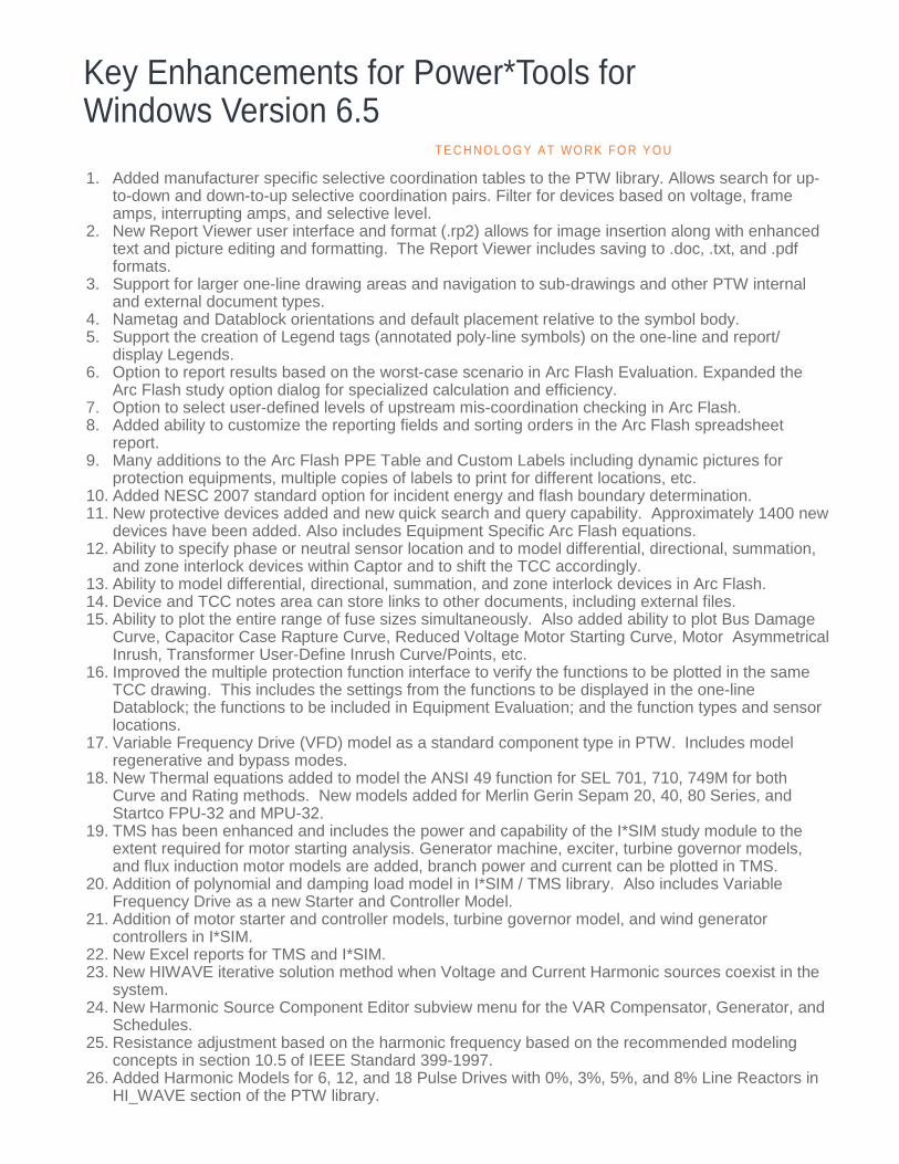
6. Option to rotate nametags and Datablocks on one-line drawings. 7. Option to specify defaults for Datablock and Nametag visibility, rotation orientation, and
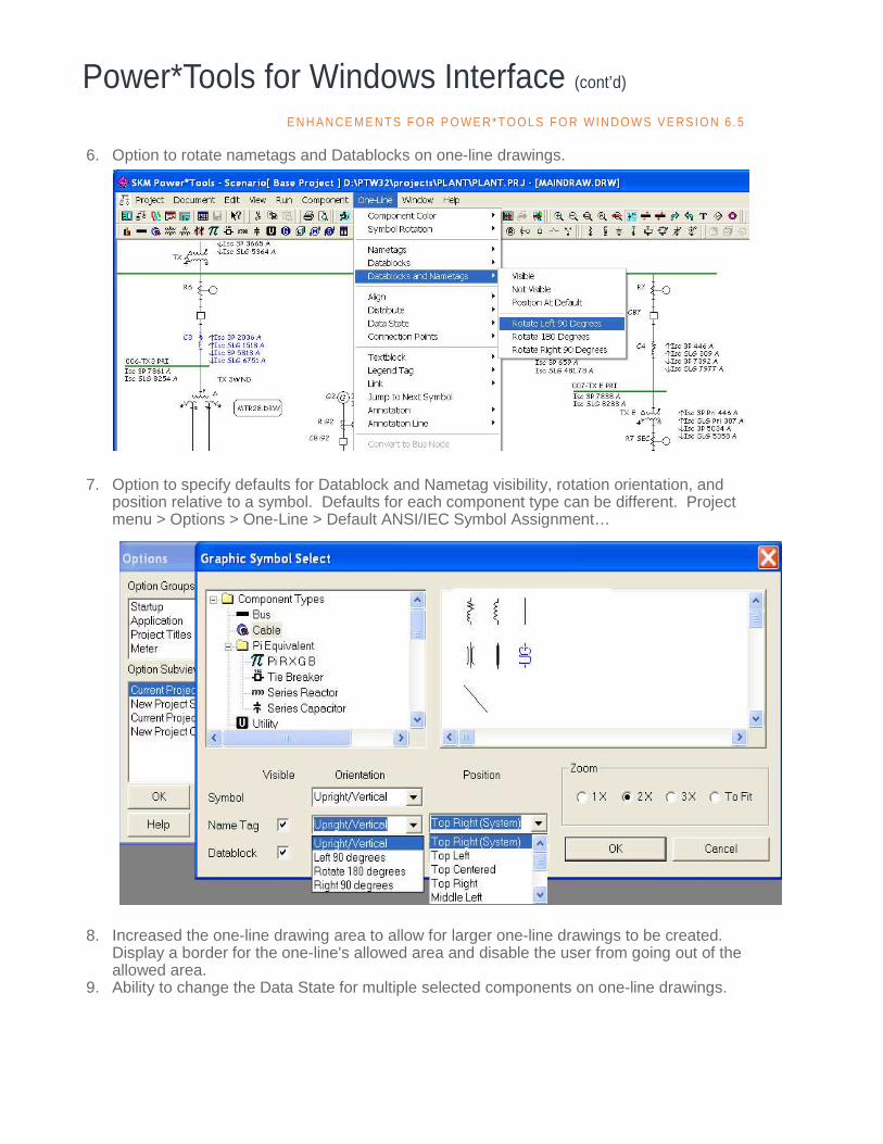
position relative to a symbol. Defaults for each component type can be different. Project menu > Options > One-Line > Default ANSI/IEC Symbol Assignment…
8. Increased the one-line drawing area to allow for larger one-line drawings to be created.
Display a border for the one-line's allowed area and disable the user from going out of the allowed area.
9. Ability to change the Data State for multiple selected components on one-line drawings.
E N H A N CE M E N TS F O R P O WE R* T O OL S F O R WI N D O WS V E RS I O N 6 .5
10. Ability to color Datablock and nametag as the symbol color. 11. Ability to color buses and protective devices using the Arc Flash Category colors. 12. Textblock to have separate color options for the text, background, and border. Border to have
line width and style. 13. Annotation Rectangle with graphical attributes. 14. Color Toolbar for Data State color, Arc Flash Category color, Input Evalaution Failed color,
Equipment Evaluation Failed color, and color Datablock and nametag as the symbol color. 15. Added “Find Not In One-Line” feature to find components that do not exist in any one-line
drawings. 16. Added the "Find In Other One-lines" feature within the one-line to find the selected component
in other one-line drawings. 17. Sort components within the “Component Existing” dialog to display components not in the
selected one-line drawings together. 18. Enhanced the One-line's Find feature to "Search" by device name and to find of next
component of the same starting character. 19. Auto Save the one-line at a user-defined interval. 20. Create a backup of the one-line for disaster recovery. 21. Mouse wheel double click for window zoom. 22. Option to "Show Difference" and "Show Comment" in the Data Visualizer. 23. Option to highlight the scenario cell with the maximum or minimum value throughout all
scenarios. 24. Option in Data Visualizer to change cell color of scenarios if values/settings are different from
the Base project. 25. Ability to model the UPS impedance in the Bypass mode. 26. Ability to model the UPS in the Reliability module. 27. VFD as a standard component type in PTW. Includes model regenerative and bypass
modes. 28. Added IEC909 Ib SLG, Ik SLG, and other IEC_909 data fields to the Datablock attributes. 29. Option to report user-definable time T1, T2, T3, and T4 in IEC363 and IEC909 Datablocks. 30. Enabled scenario names to be used in Crystal Reports and Arc Flash labels. 31. Option in the TCC Starting Curve subview to "Link Inrush with SC Contribution". 32. LRA as input data and option in the ANSI/IEC Contribution subview to "Link X/R with Starting
PF" (locked rotor PF) and link Xd” with LRA. 33. Option in the Transformer Impedance subview to Size To "Full Load kVA or Nominal kVA". 34. Added Manufacturer name and Type field for 3-winding transformers. 35. Provide a Motor Loading Table in Project > Options > Motor to specific global table for
different load factors and their associated power factors and efficiencies. 36. Option in Component Editor for Induction Motors to use the Global Table or store the different
load factors and their associated power factors and efficiencies with each individual Motors. 37. Allow both Fed From Buses and Schedules to be displayed in the schedule component in the
Component Editor. 38. New paper sizes for Print Using Forms: ANSI A, B, C, D, E ANSI Arch A, B, C, D, E, E1 ISO A0, A1, A2, A3, A4 ISO B0, B1, B2, B3, B4 39. Five Project Titles in the Options > Project Titles and Logo subview are now displayed in
Datablock reports and Crystal Reports. 40. New "Device Notes" dialog for all components. Ability to enter extended notes with locations/
links to other documents and to launch these external documents
Power*Tools for Windows Interface (cont’d)

41. Consolidated all report options into one dialog for selection of different report types.
42. New expanded Report Viewer user interface and format (.rp2) allows for image insertion along with enhanced text and picture editing and formatting. The Report Viewer includes saving to .doc, .txt, and .pdf formats.
Power*Tools for Windows Interface (cont’d) E N H A N CE M E N TS F O R P O WE R* T O OL S F O R WI N D O WS V E RS I O N 6 .5
Arc Flash Evaluation
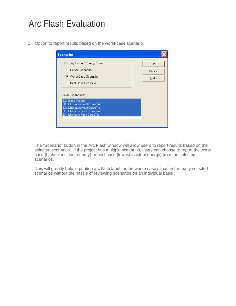
1. Option to report results based on the worst-case scenario.
The “Scenario” button in the Arc Flash window will allow users to report results based on the selected scenarios. If the project has multiple scenarios, users can choose to report the worst case (highest incident energy) or best case (lowest incident energy) from the selected scenarios.
This will greatly help in printing arc flash label for the worse case situation for many selected scenarios without the hassle of reviewing scenarios on an individual basis .
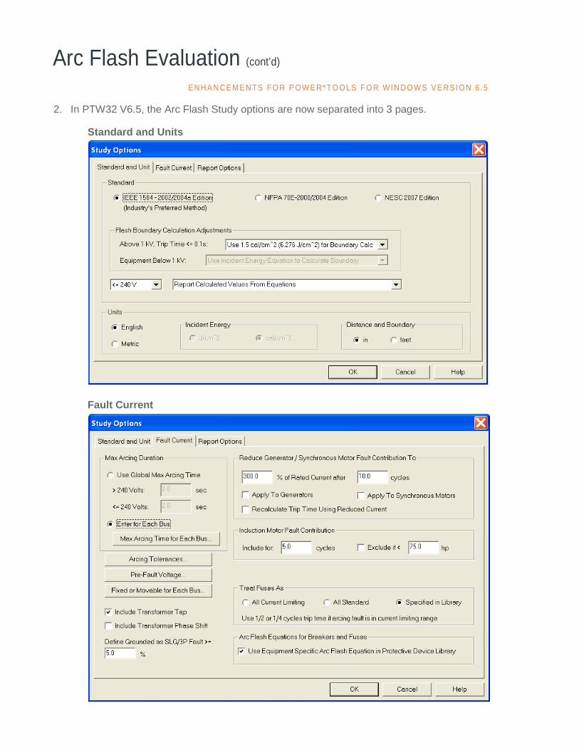
2. In PTW32 V6.5, the Arc Flash Study options are now separated into 3 pages. Standard and Units Fault Current
Arc Flash Evaluation (cont’d) E N H A N CE M E N TS F O R P O WE R* T O OL S F O R WI N D O WS V E RS I O N 6 .5

Report Options 3. Added ability to allow users to customize how all twenty available fields are to be displayed in
the Arc Flash spreadsheet report. Furthermore, the user can also specify the order in which they will appear in the Arc Flash spreadsheet report.
For instance, if you don’t want to show the equipment type, you can simply uncheck the display checkbox next to that field. If you want the “Bus kV” field to show up on the first col-umn, you can just type in the number “1” in the column order next to that field and the bus voltage will them show up on the first column of the report. You can access “Report Data & Order” window by clicking on the “Report Data & Order” button in the “Report Options” tab of the Arc Flash Study Options window.
Arc Flash Evaluation (cont’d)
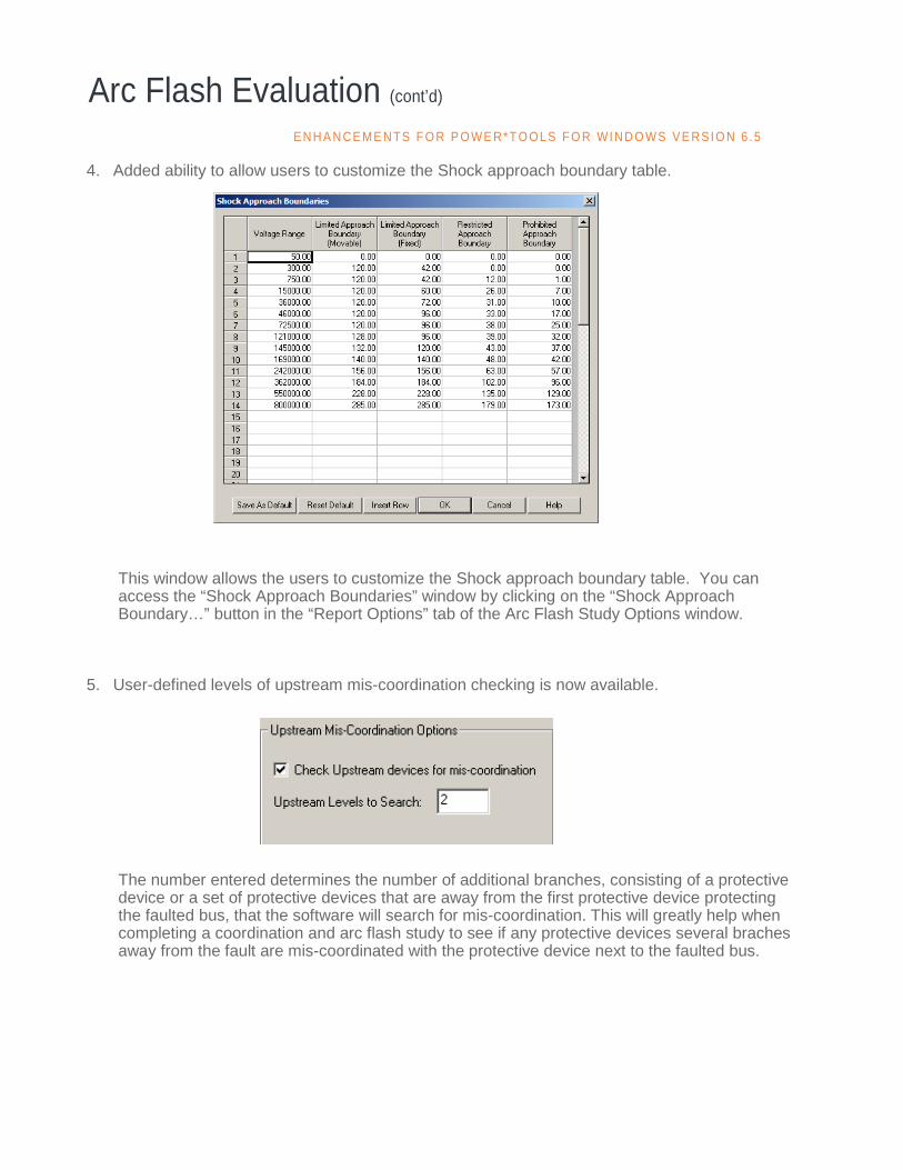
4. Added ability to allow users to customize the Shock approach boundary table.
This window allows the users to customize the Shock approach boundary table. You can access the “Shock Approach Boundaries” window by clicking on the “Shock Approach Boundary…” button in the “Report Options” tab of the Arc Flash Study Options window.
5. User-defined levels of upstream mis-coordination checking is now available.
The number entered determines the number of additional branches, consisting of a protective device or a set of protective devices that are away from the first protective device protecting the faulted bus, that the software will search for mis-coordination. This will greatly help when completing a coordination and arc flash study to see if any protective devices several braches away from the fault are mis-coordinated with the protective device next to the faulted bus.
Arc Flash Evaluation (cont’d) E N H A N CE M E N TS F O R P O WE R* T O OL S F O R WI N D O WS V E RS I O N 6 .5

6. Arc Flash Label # with user-definable prefixes. Label # is available within Datablocks and custom labels.
Default Label # Prefix - This allows the user to specify the prefix character that will go on the "Label #" column in the Arc Flash spreadsheet report. This field can help organizing labels when they are printed.
7. Ability to enable/disable the “Auto Update Study Result” feature.
When this checkbox is checked, the software will automatically update the arc flash results when there is a change in the system model. For instance, when user opens up a tie-breaker or change the size of a motor in the system model, the software will automatically update the arc flash results based on those changes. Users will not need to re-run the arc flash study.
8. Ability to specify the Maximum Arcing Duration for each bus.
In this window, users can specify the maximum arcing duration for each buses in the system modeled. For convenience, users can also sort the window by bus name, bus voltage, or maximum arcing duration by selection one of the available options button.
Furthermore, users can change the maximum arcing duration of all the buses globally by clicking on the “Global Change” button. This helps in modeling your system accurately for arc flash study, since each bus location you are analyzing may have different maximum arcing duration depending on the situation.
Users can access “Maximum Arcing Duration for Each Bus” window by clicking on the “Maximum Arcing Time For Each Bus” button in the “Fault Current” tab of the Arc Flash Study Options window.
Arc Flash Evaluation (cont’d)
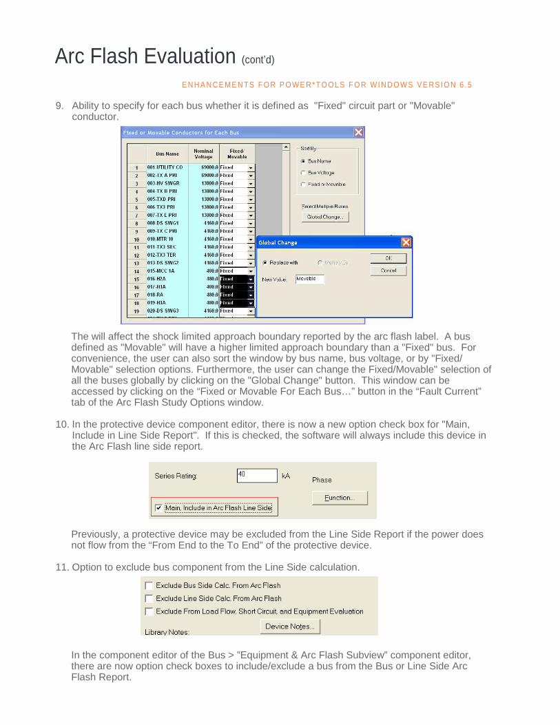
9. Ability to specify for each bus whether it is defined as "Fixed" circuit part or "Movable" conductor.
The will affect the shock limited approach boundary reported by the arc flash label. A bus defined as "Movable" will have a higher limited approach boundary than a "Fixed" bus. For convenience, the user can also sort the window by bus name, bus voltage, or by "Fixed/Movable" selection options. Furthermore, the user can change the Fixed/Movable" selection of all the buses globally by clicking on the "Global Change" button. This window can be accessed by clicking on the “Fixed or Movable For Each Bus…” button in the “Fault Current” tab of the Arc Flash Study Options window.
10. In the protective device component editor, there is now a new option check box for "Main,
Include in Line Side Report". If this is checked, the software will always include this device in the Arc Flash line side report.
Previously, a protective device may be excluded from the Line Side Report if the power does not flow from the “From End to the To End” of the protective device.
11. Option to exclude bus component from the Line Side calculation.
In the component editor of the Bus > ”Equipment & Arc Flash Subview” component editor, there are now option check boxes to include/exclude a bus from the Bus or Line Side Arc Flash Report.
Arc Flash Evaluation (cont’d) E N H A N CE M E N TS F O R P O WE R* T O OL S F O R WI N D O WS V E RS I O N 6 .5

12. Exclude Bus and Line Side from Arc Flash Calculation automatically when user switches from a regular Bus to a Node Bus.
13. Ability to model the 2 and 3 winding transformer instantaneous protection for protective device
Line Side calculations.
In the 2 and 3 winding transformer component editor, there is now an check box option to model special instantaneous protection for protective device Line Side calculations.
14. Ability to increase the arc flash PPE results by 1 category whenever the calculated incident
energy is greater than the high marginal value set in the PPE table. 15. Added IE Low Marginal and IE High Marginal columns in the PPE table
The values entered in the “IE Low Marginal” and “IE High Marginal” columns are the low and high threshold value of for each category. If the calculated incident is higher than “IE High Marginal” entered for that category and “Increase PPE Category by 1 for high IE” checkbox is checked, the software will automatically increase the arc flash PPE category results by 1 in the main report and labels.
Arc Flash Evaluation (cont’d)

16. Reserved another row for the PPE table for the Dangerous category
This allows the users the flexibility to add descriptions for the Notes, Head & Eye Protection, Hand & Arm Protection, Foot Protection, and other columns for the PPE Dangerous category.
17. Four dynamic pictures for each PPE Category can be specified. Switching pictures among the
categories is done automatically. In the PPE table, there are now four new picture columns where the user can specify different pictures or logos for each PPE Category. This allows the users the flexibility to add up to four different pictures or logos for each PPE category in their custom arc flash label.
Arc Flash Evaluation (cont’d) E N H A N CE M E N TS F O R P O WE R* T O OL S F O R WI N D O WS V E RS I O N 6 .5
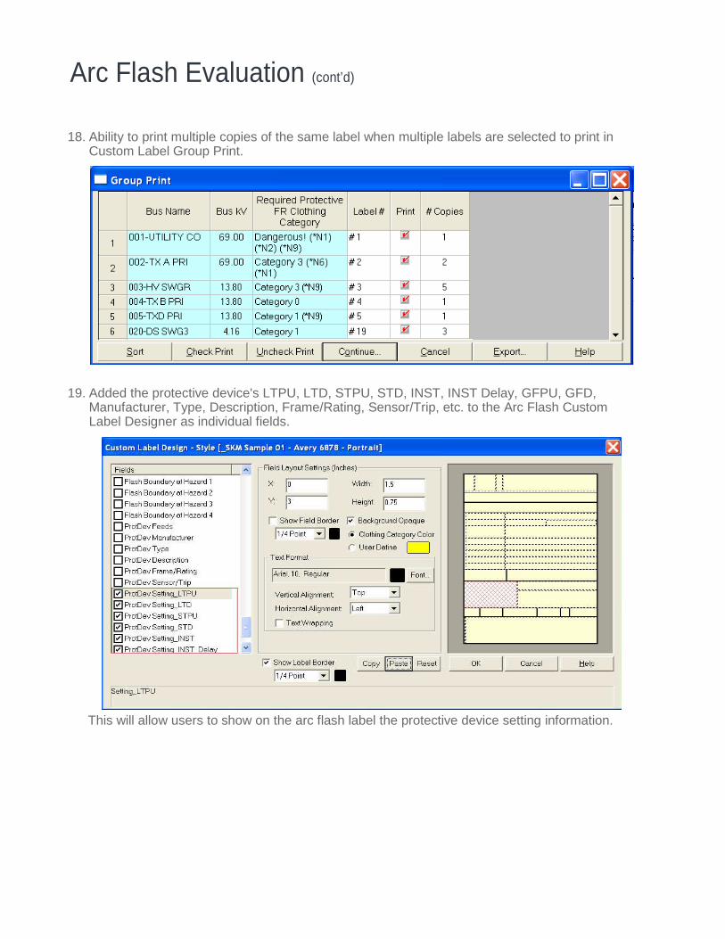
18. Ability to print multiple copies of the same label when multiple labels are selected to print in Custom Label Group Print.
19. Added the protective device's LTPU, LTD, STPU, STD, INST, INST Delay, GFPU, GFD,
Manufacturer, Type, Description, Frame/Rating, Sensor/Trip, etc. to the Arc Flash Custom Label Designer as individual fields.
This will allow users to show on the arc flash label the protective device setting information.
Arc Flash Evaluation (cont’d)

20. Increased the number of allowable picture fields to eight for Arc Flash labels. 21. When “Metric” unit is selected, provided option to report incident energy as cal/cm^2 and flash
boundary/working distance in mm, cm, m. When “English” unit is selected, option is provided to report flash boundary/working distance in inches or feet.
22. Expanded the Arcing Fault and UDF Flags window.
Arc Flash Evaluation (cont’d) E N H A N CE M E N TS F O R P O WE R* T O OL S F O R WI N D O WS V E RS I O N 6 .5
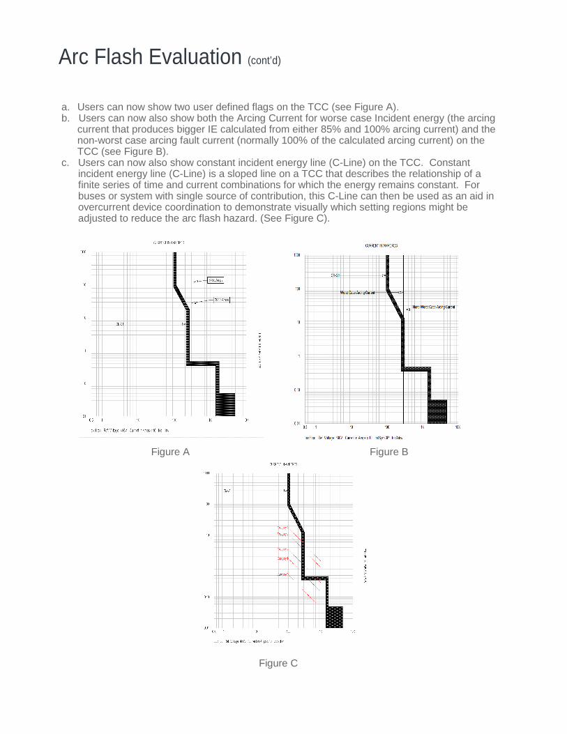
a. Users can now show two user defined flags on the TCC (see Figure A). b. Users can now also show both the Arcing Current for worse case Incident energy (the arcing
current that produces bigger IE calculated from either 85% and 100% arcing current) and the non-worst case arcing fault current (normally 100% of the calculated arcing current) on the TCC (see Figure B).
c. Users can now also show constant incident energy line (C-Line) on the TCC. Constant incident energy line (C-Line) is a sloped line on a TCC that describes the relationship of a finite series of time and current combinations for which the energy remains constant. For buses or system with single source of contribution, this C-Line can then be used as an aid in overcurrent device coordination to demonstrate visually which setting regions might be adjusted to reduce the arc flash hazard. (See Figure C).
Figure A Figure B Figure C
Arc Flash Evaluation (cont’d)

23. Added NESC 2007 standard option for calculating incident energy and flash boundary
If NESC 2007 method is selected, the tables from NESC 2007 are used to calculate the incident energy and minimum approach distance.
24. Added a window to specify default arc flash settings for new projects. 25. Support additional Protection Function Types (Over Current, Differential, Directional,
Summation, and Zone Interlocking) in the Arc Flash equation.
Arc Flash Evaluation (cont’d) E N H A N CE M E N TS F O R P O WE R* T O OL S F O R WI N D O WS V E RS I O N 6 .5
CAPTOR
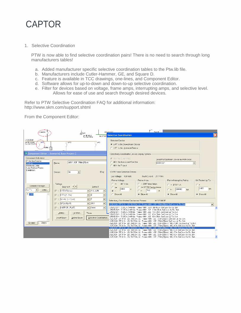
1. Selective Coordination
PTW is now able to find selective coordination pairs! There is no need to search through long manufacturers tables!
a. Added manufacturer specific selective coordination tables to the Ptw.lib file. b. Manufacturers include Cutler-Hammer, GE, and Square D. c. Feature is available in TCC drawings, one-lines, and Component Editor. d. Software allows for up-to-down and down-to-up selective coordination. e. Filter for devices based on voltage, frame amps, interrupting amps, and selective level.
Allows for ease of use and search through desired devices. Refer to PTW Selective Coordination FAQ for additional information: http://www.skm.com/support.shtml From the Component Editor:
CAPTOR (cont’d)
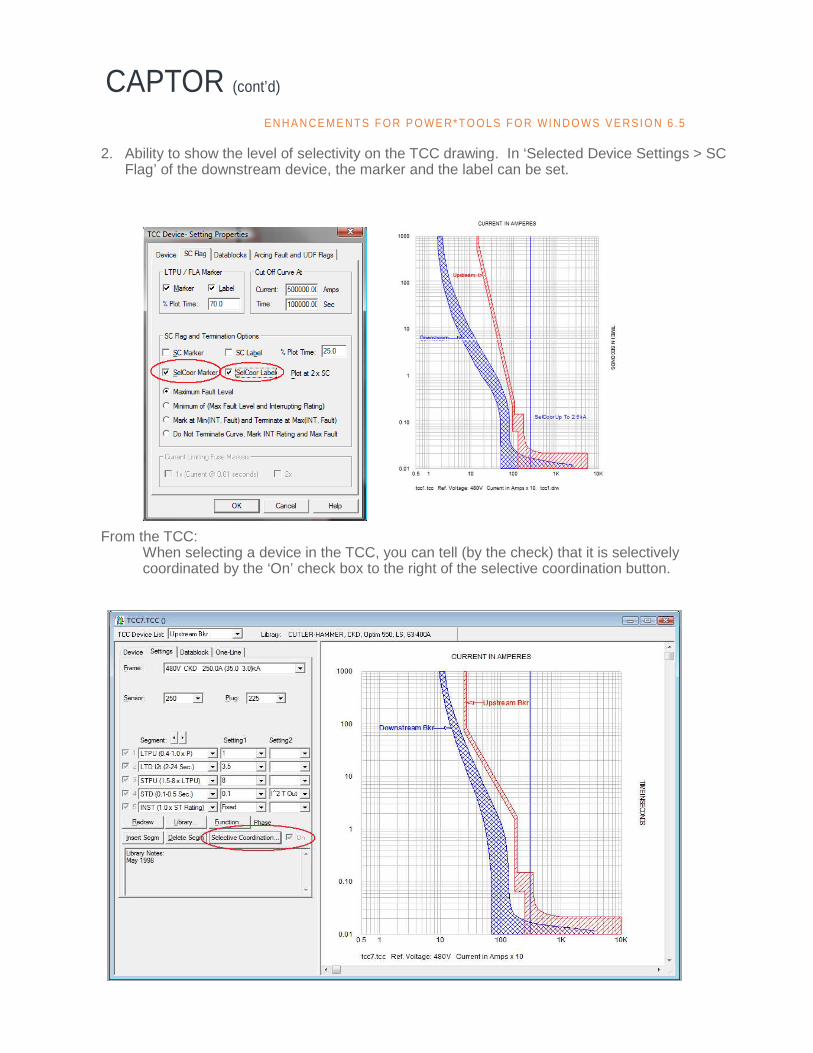
2. Ability to show the level of selectivity on the TCC drawing. In ‘Selected Device Settings > SC Flag’ of the downstream device, the marker and the label can be set.
From the TCC:
When selecting a device in the TCC, you can tell (by the check) that it is selectively coordinated by the ‘On’ check box to the right of the selective coordination button.
E N H A N CE M E N TS F O R P O WE R* T O OL S F O R WI N D O WS V E RS I O N 6 .5
CAPTOR (cont’d)
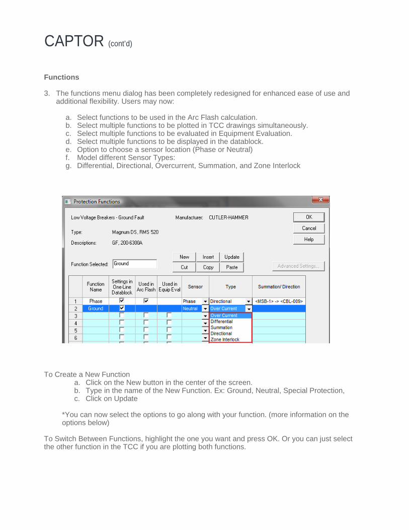
Functions 3. The functions menu dialog has been completely redesigned for enhanced ease of use and
additional flexibility. Users may now:
a. Select functions to be used in the Arc Flash calculation. b. Select multiple functions to be plotted in TCC drawings simultaneously. c. Select multiple functions to be evaluated in Equipment Evaluation. d. Select multiple functions to be displayed in the datablock. e. Option to choose a sensor location (Phase or Neutral) f. Model different Sensor Types: g. Differential, Directional, Overcurrent, Summation, and Zone Interlock
To Create a New Function
a. Click on the New button in the center of the screen. b. Type in the name of the New Function. Ex: Ground, Neutral, Special Protection, c. Click on Update
*You can now select the options to go along with your function. (more information on the options below)
To Switch Between Functions, highlight the one you want and press OK. Or you can just select the other function in the TCC if you are plotting both functions.
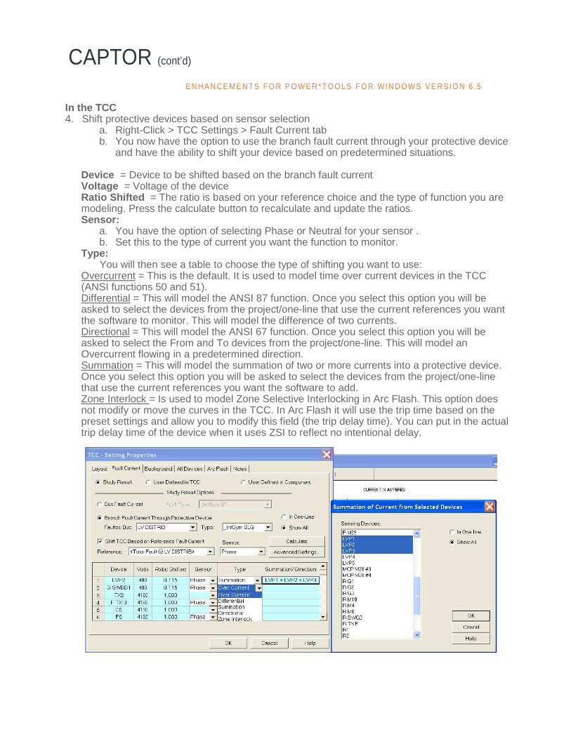
In the TCC 4. Shift protective devices based on sensor selection
a. Right-Click > TCC Settings > Fault Current tab b. You now have the option to use the branch fault current through your protective device
and have the ability to shift your device based on predetermined situations.
Device = Device to be shifted based on the branch fault current Voltage = Voltage of the device Ratio Shifted = The ratio is based on your reference choice and the type of function you are modeling. Press the calculate button to recalculate and update the ratios. Sensor:
a. You have the option of selecting Phase or Neutral for your sensor . b. Set this to the type of current you want the function to monitor.
Type: You will then see a table to choose the type of shifting you want to use:
Overcurrent = This is the default. It is used to model time over current devices in the TCC (ANSI functions 50 and 51). Differential = This will model the ANSI 87 function. Once you select this option you will be asked to select the devices from the project/one-line that use the current references you want the software to monitor. This will model the difference of two currents. Directional = This will model the ANSI 67 function. Once you select this option you will be asked to select the From and To devices from the project/one-line. This will model an Overcurrent flowing in a predetermined direction. Summation = This will model the summation of two or more currents into a protective device. Once you select this option you will be asked to select the devices from the project/one-line that use the current references you want the software to add. Zone Interlock = Is used to model Zone Selective Interlocking in Arc Flash. This option does not modify or move the curves in the TCC. In Arc Flash it will use the trip time based on the preset settings and allow you to modify this field (the trip delay time). You can put in the actual trip delay time of the device when it uses ZSI to reflect no intentional delay.
CAPTOR (cont’d) E N H A N CE M E N TS F O R P O WE R* T O OL S F O R WI N D O WS V E RS I O N 6 .5
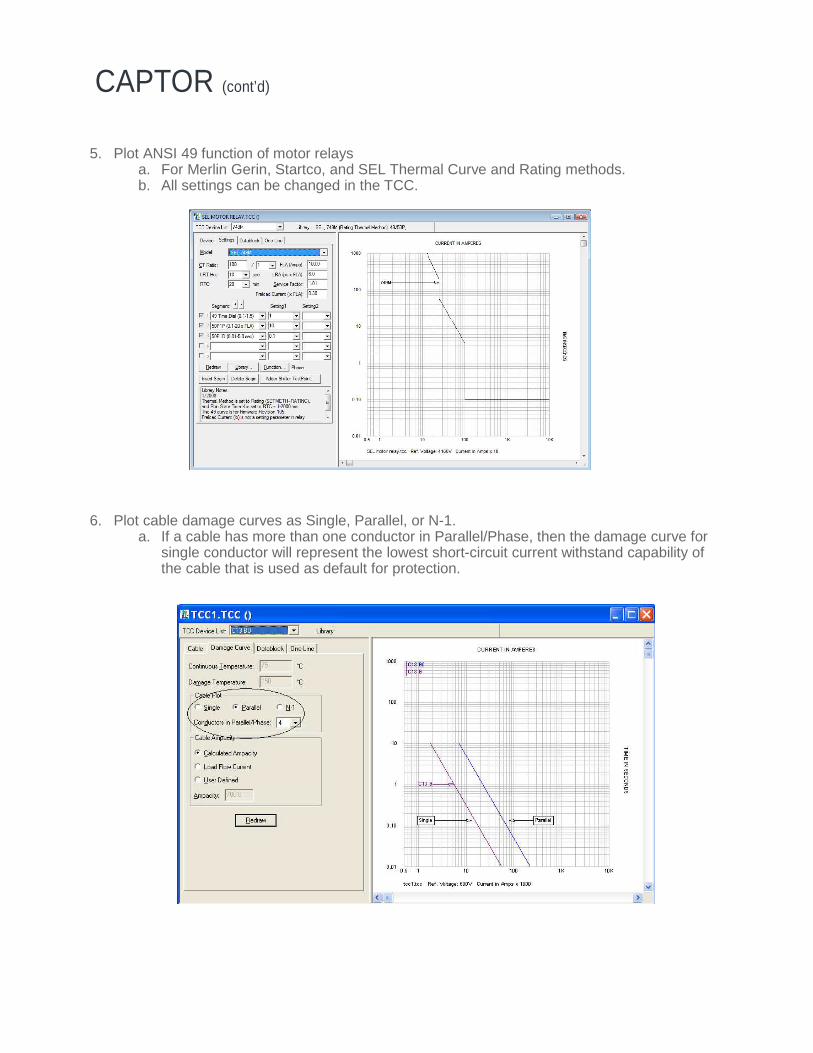
5. Plot ANSI 49 function of motor relays a. For Merlin Gerin, Startco, and SEL Thermal Curve and Rating methods. b. All settings can be changed in the TCC.
6. Plot cable damage curves as Single, Parallel, or N-1.
a. If a cable has more than one conductor in Parallel/Phase, then the damage curve for single conductor will represent the lowest short-circuit current withstand capability of the cable that is used as default for protection.
CAPTOR (cont’d)
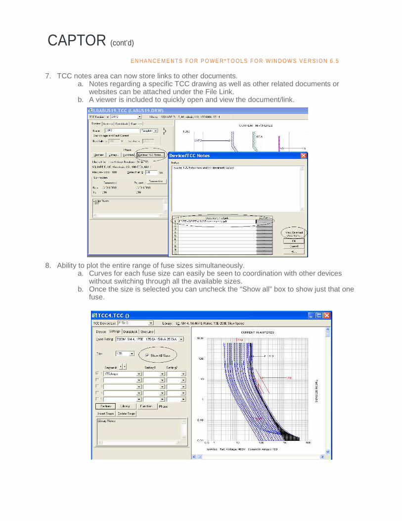
7. TCC notes area can now store links to other documents. a. Notes regarding a specific TCC drawing as well as other related documents or
websites can be attached under the File Link. b. A viewer is included to quickly open and view the document/link.
8. Ability to plot the entire range of fuse sizes simultaneously.
a. Curves for each fuse size can easily be seen to coordination with other devices without switching through all the available sizes.
b. Once the size is selected you can uncheck the “Show all” box to show just that one fuse.
CAPTOR (cont’d) E N H A N CE M E N TS F O R P O WE R* T O OL S F O R WI N D O WS V E RS I O N 6 .5
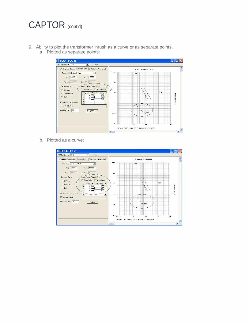
9. Ability to plot the transformer inrush as a curve or as separate points. a. Plotted as separate points: b. Plotted as a curve:
CAPTOR (cont’d)

10. Show FLA markers based on Full load kVA a. Users may select the transformer’s FLA marker to be plotted at the nominal or full load
rating: b. Right-click on the TCC drawing > Selected device settings > SC Flag tab
11. Added ability to plot user-defined capacitor and bus damage curves.
a. Capacitor: User-defined curve
CAPTOR (cont’d) E N H A N CE M E N TS F O R P O WE R* T O OL S F O R WI N D O WS V E RS I O N 6 .5
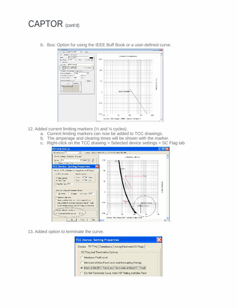
b. Bus: Option for using the IEEE Buff Book or a user-defined curve. 12. Added current limiting markers (½ and ¼ cycles).
a. Current limiting markers can now be added to TCC drawings. b. The amperage and clearing times will be shown with the marker. c. Right-click on the TCC drawing > Selected device settings > SC Flag tab
13. Added option to terminate the curve.
CAPTOR (cont’d)

14. Ability to specify and report the time adder and shifter for each device in the TCC.
15. Ability to plot the motor asymmetrical inrush current. a. Option in the TCC to plot the Asymmetrical Inrush using: i. FLA x Inrush x 1.6 (default) or any user-defined value. Ii. Option to choose the maximum time in seconds to plot.
16. Ability to plot a 2nd reduced voltage motor starting curve in the TCC with user-defined or
default parameters. The dotted line below shows a 80% reduced voltage curve.
CAPTOR (cont’d) E N H A N CE M E N TS F O R P O WE R* T O OL S F O R WI N D O WS V E RS I O N 6 .5
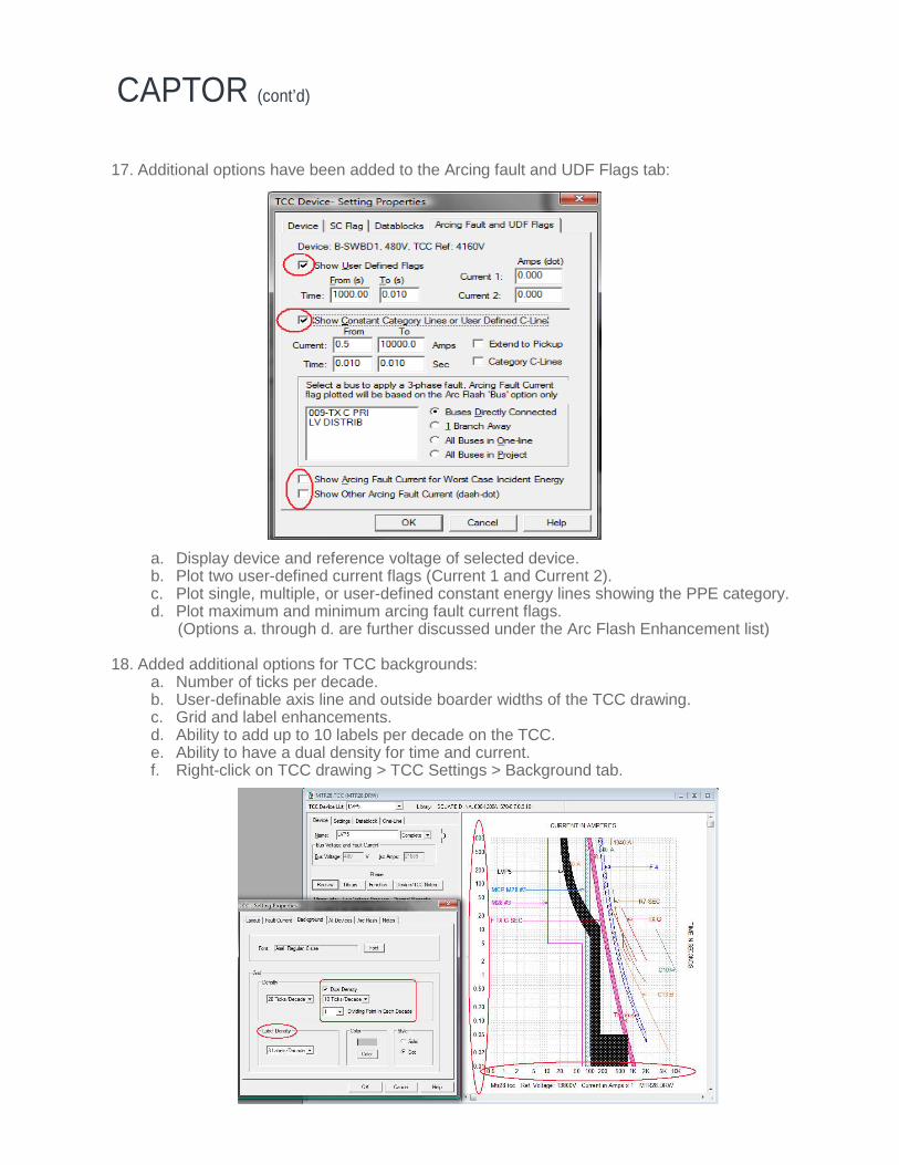
17. Additional options have been added to the Arcing fault and UDF Flags tab:
a. Display device and reference voltage of selected device. b. Plot two user-defined current flags (Current 1 and Current 2). c. Plot single, multiple, or user-defined constant energy lines showing the PPE category. d. Plot maximum and minimum arcing fault current flags. (Options a. through d. are further discussed under the Arc Flash Enhancement list)
18. Added additional options for TCC backgrounds:
a. Number of ticks per decade. b. User-definable axis line and outside boarder widths of the TCC drawing. c. Grid and label enhancements. d. Ability to add up to 10 labels per decade on the TCC. e. Ability to have a dual density for time and current. f. Right-click on TCC drawing > TCC Settings > Background tab.
CAPTOR (cont’d)

19. Ability to add the fault current type to TCC drawing and Forms. Right-click on TCC drawing > TCC Settings > Show Fault Type.
20. Include or exclude cables, buses, and capacitors from the TCC “GoTo” command.
CAPTOR (cont’d) E N H A N CE M E N TS F O R P O WE R* T O OL S F O R WI N D O WS V E RS I O N 6 .5

21. Added multiple voltage scales on TCC drawings. a. When plotting devices of varying voltage levels on the TCC, you now have the option to
show the conversion factor between them. b. Right-click on TCC drawing > TCC Settings > Layout tab.
22. Use highest or lowest voltage as the reference in TCC drawings.
a. Option to use the highest or lowest voltage of the selected devices when creating a TCC drawing from the GoTo menu.
b. Go to: Project > Options > TCC > TCC Layout.
CAPTOR (cont’d)
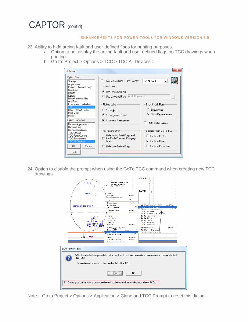
23. Ability to hide arcing fault and user-defined flags for printing purposes. a. Option to not display the arcing fault and user defined flags on TCC drawings when
printing. b. Go to: Project > Options > TCC > TCC All Devices :
24. Option to disable the prompt when using the GoTo TCC command when creating new TCC
drawings. Note: Go to Project > Options > Application > Clone and TCC Prompt to reset this dialog.
CAPTOR (cont’d) E N H A N CE M E N TS F O R P O WE R* T O OL S F O R WI N D O WS V E RS I O N 6 .5
25. Ability to print onto K&E paper. a. New form template has been created for K&E paper. b. User-definable line widths of the axis lines and outside borders of the TCC.
26. Multiple Protection Functions can now be displayed on the one-line Datablock. Project > Options > Application > Datablock
a. Show Multiple Settings Only b. Show Multiple Functions (All) c. Show Multiple Settings + CTs
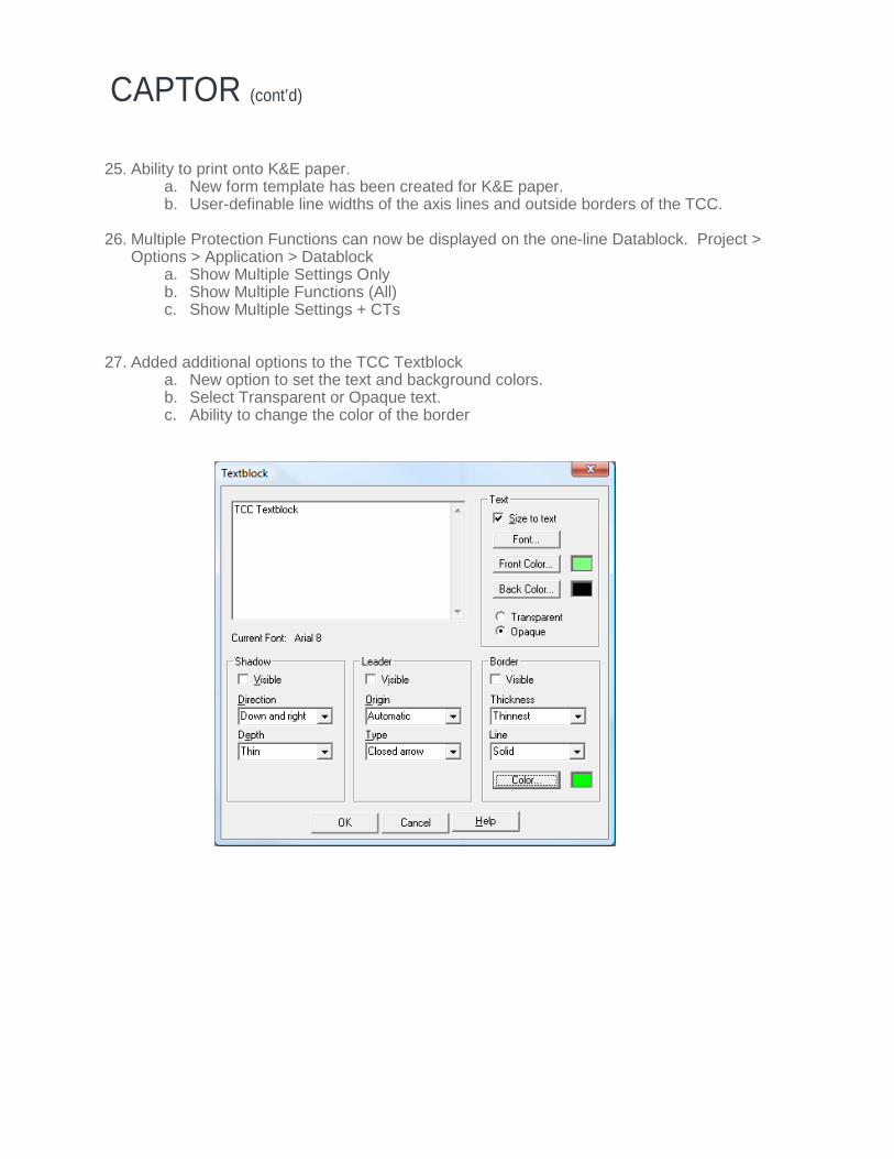
27. Added additional options to the TCC Textblock
a. New option to set the text and background colors. b. Select Transparent or Opaque text. c. Ability to change the color of the border
CAPTOR (cont’d)
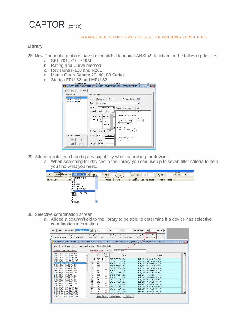
Library 28. New Thermal equations have been added to model ANSI 49 function for the following devices:
a. SEL 701, 710, 749M b. Rating and Curve method c. Revisions R100 and R201 d. Merlin Gerin Sepam 20, 40, 80 Series e. Startco FPU-32 and MPU-32
29. Added quick search and query capability when searching for devices.
a. When searching for devices in the library you can use up to seven filter criteria to help you find what you need.
30. Selective coordination screen
a. Added a column/field to the library to be able to determine if a device has selective coordination information.
CAPTOR (cont’d) E N H A N CE M E N TS F O R P O WE R* T O OL S F O R WI N D O WS V E RS I O N 6 .5
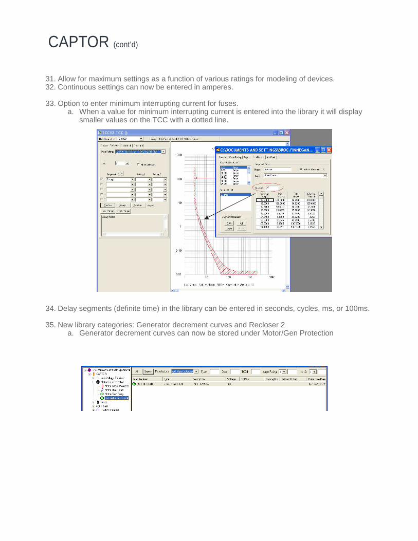
31. Allow for maximum settings as a function of various ratings for modeling of devices. 32. Continuous settings can now be entered in amperes. 33. Option to enter minimum interrupting current for fuses.
a. When a value for minimum interrupting current is entered into the library it will display smaller values on the TCC with a dotted line.
34. Delay segments (definite time) in the library can be entered in seconds, cycles, ms, or 100ms. 35. New library categories: Generator decrement curves and Recloser 2
a. Generator decrement curves can now be stored under Motor/Gen Protection
CAPTOR (cont’d)
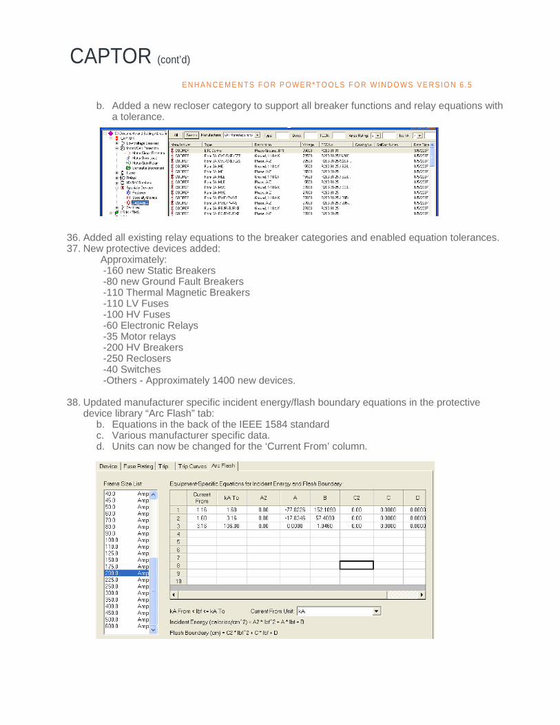
b. Added a new recloser category to support all breaker functions and relay equations with a tolerance.
36. Added all existing relay equations to the breaker categories and enabled equation tolerances. 37. New protective devices added: Approximately:
-160 new Static Breakers -80 new Ground Fault Breakers -110 Thermal Magnetic Breakers -110 LV Fuses -100 HV Fuses -60 Electronic Relays -35 Motor relays -200 HV Breakers -250 Reclosers -40 Switches -Others - Approximately 1400 new devices.
38. Updated manufacturer specific incident energy/flash boundary equations in the protective
device library “Arc Flash” tab: b. Equations in the back of the IEEE 1584 standard c. Various manufacturer specific data. d. Units can now be changed for the ‘Current From’ column.
CAPTOR (cont’d) E N H A N CE M E N TS F O R P O WE R* T O OL S F O R WI N D O WS V E RS I O N 6 .5
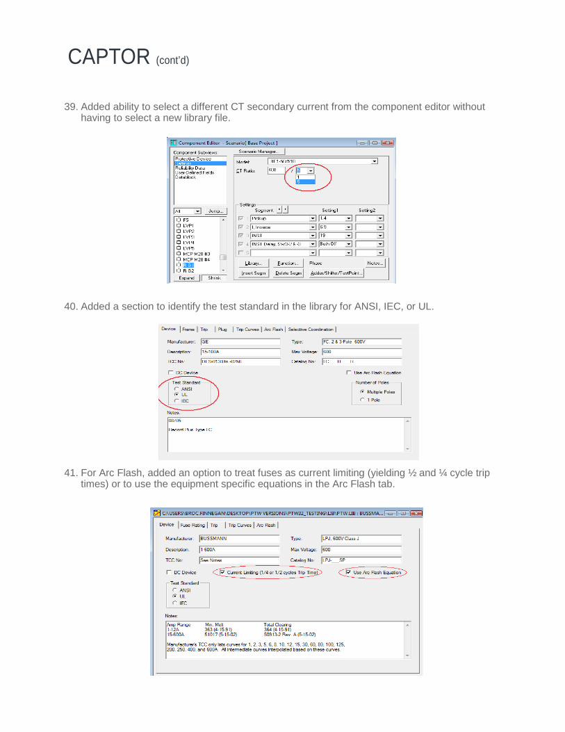
39. Added ability to select a different CT secondary current from the component editor without having to select a new library file.
40. Added a section to identify the test standard in the library for ANSI, IEC, or UL. 41. For Arc Flash, added an option to treat fuses as current limiting (yielding ½ and ¼ cycle trip
times) or to use the equipment specific equations in the Arc Flash tab.
CAPTOR (cont’d)
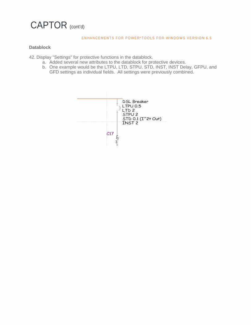
Datablock 42. Display "Settings" for protective functions in the datablock.
a. Added several new attributes to the datablock for protective devices. b. One example would be the LTPU, LTD, STPU, STD, INST, INST Delay, GFPU, and
GFD settings as individual fields. All settings were previously combined.
CAPTOR (cont’d) E N H A N CE M E N TS F O R P O WE R* T O OL S F O R WI N D O WS V E RS I O N 6 .5
DAPPER, A_FAULT, and Sizing
1. Swing bus definition is no longer required for all fault calculations. The generator with the biggest kVA rating as the swing bus will be used to provide fault current calculations.
2. Option to include or exclude
Load Flow Current in the Comprehensive Fault.
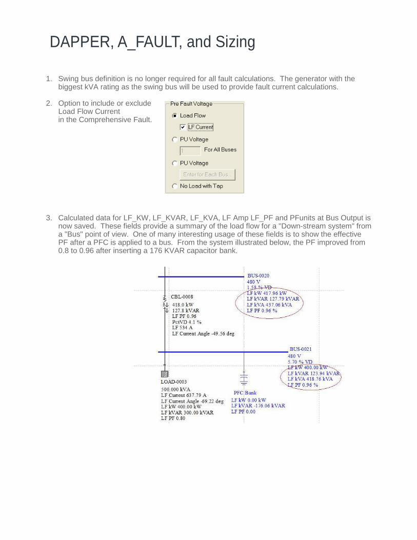
3. Calculated data for LF_KW, LF_KVAR, LF_KVA, LF Amp LF_PF and PFunits at Bus Output is
now saved. These fields provide a summary of the load flow for a "Down-stream system" from a "Bus" point of view. One of many interesting usage of these fields is to show the effective PF after a PFC is applied to a bus. From the system illustrated below, the PF improved from 0.8 to 0.96 after inserting a 176 KVAR capacitor bank.
DAPPER, A_FAULT, and Sizing (cont’d)
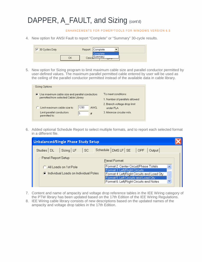
4. New option for ANSI Fault to report “Complete” or “Summary” 30-cycle results. 5. New option for Sizing program to limit maximum cable size and parallel conductor permitted by
user-defined values. The maximum parallel permitted cable entered by user will be used as the ceiling of the parallel conductor permitted instead of the available data in cable library.
6. Added optional Schedule Report to select multiple formats, and to report each selected format
in a different file.
7. Content and name of ampacity and voltage drop reference tables in the IEE Wiring category of the PTW library has been updated based on the 17th Edition of the IEE Wiring Regulations.
8. IEE Wiring cable library consists of new descriptions based on the updated names of the ampacity and voltage drop tables in the 17th Edition.
E N H A N CE M E N TS F O R P O WE R* T O OL S F O R WI N D O WS V E RS I O N 6 .5

TRANSIENT MOTOR STARTING (TMS)
TMS has been enhanced and includes the power and capability of the I*SIM study module to the extent required for motor starting analysis. Modeling 1. Added access and application of dynamic models for sources of supply such as generators
and utilities in TMS > Source Model Setup. This was previously available only in the I*SIM study module.
2. Addition of Flux Induction Motor modeling concept to Motor Model in I*SIM / TMS library.
TRANSIENT MOTOR STARTING (TMS) (cont’d)
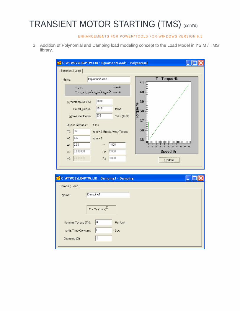
3. Addition of Polynomial and Damping load modeling concept to the Load Model in I*SIM / TMS library.
E N H A N CE M E N TS F O R P O WE R* T O OL S F O R WI N D O WS V E RS I O N 6 .5
TRANSIENT MOTOR STARTING (TMS) (cont’d)
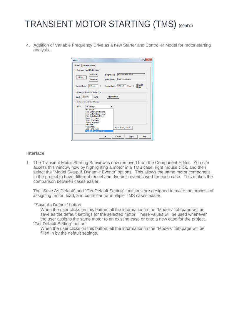
4. Addition of Variable Frequency Drive as a new Starter and Controller Model for motor starting analysis.
Interface 1. The Transient Motor Starting Subview is now removed from the Component Editor. You can
access this window now by highlighting a motor in a TMS case, right mouse click, and then select the “Model Setup & Dynamic Events” options. This allows the same motor component in the project to have different model and dynamic event saved for each case. This makes the comparison between cases easier.
The “Save As Default” and “Get Default Setting” functions are designed to make the process of assigning motor, load, and controller for multiple TMS cases easier. “Save As Default” button When the user clicks on this button, all the information in the "Models" tab page will be save as the default settings for the selected motor. These values will be used whenever the user assigns the same motor to an existing case or onto a new case for the project. “Get Default Setting” button When the user clicks on this button, all the information in the "Models" tab page will be filled in by the default settings.
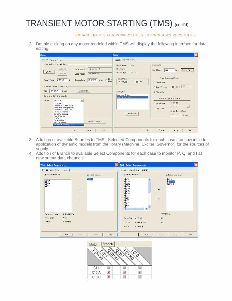
2. Double clicking on any motor modeled within TMS will display the following interface for data editing.
3. Addition of available Sources to TMS. Selected Components for each case can now include application of dynamic models from the library (Machine, Exciter, Governor) for the sources of supply.
4. Addition of Branch to available Select Components for each case to monitor P, Q, and I as new output data channels.
TRANSIENT MOTOR STARTING (TMS) (cont’d) E N H A N CE M E N TS F O R P O WE R* T O OL S F O R WI N D O WS V E RS I O N 6 .5
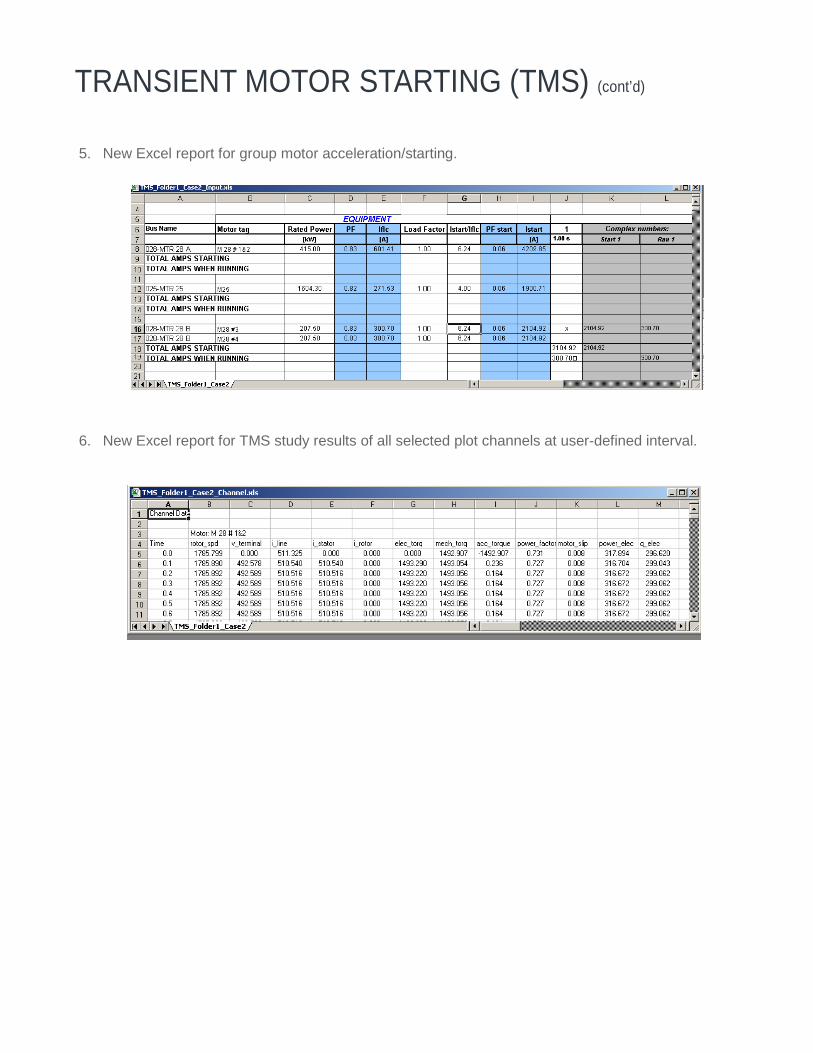
5. New Excel report for group motor acceleration/starting. 6. New Excel report for TMS study results of all selected plot channels at user-defined interval.
TRANSIENT MOTOR STARTING (TMS) (cont’d)

HI_WAVE
1. Added new Harmonic Source Subview to Component Editor for the VAR Compensator, Generator, and Schedules components as the source of harmonic for HI_WAVE.
2. Added Harmonic Models for 6, 12, and 18 Pulse Drives with 0%, 3%, 5%, and 8% Line
Reactors in HI_WAVE section of PTW library. 3. The resistance portion of Synchronous Generator, Cable, and Transmission Line components
are now changed based on the harmonic frequency per recommended modeling concept in section 10.5 of IEEE Standard 399-1997 (Brown Book).
4. The impact of motor drive AC reactor on reduction of injected harmonic currents by the drive
can now be considered through adding the Line Reactor % to Motor Controller (VFD).
E N H A N CE M E N TS F O R P O WE R* T O OL S F O R WI N D O WS V E RS I O N 6 .5
HI_WAVE (cont’d)
5. The Voltage and Current Distortion models from HI_WAVE Library can now be used at the same time to represent the impact of both on the total voltage and current Distortions in electrical system.
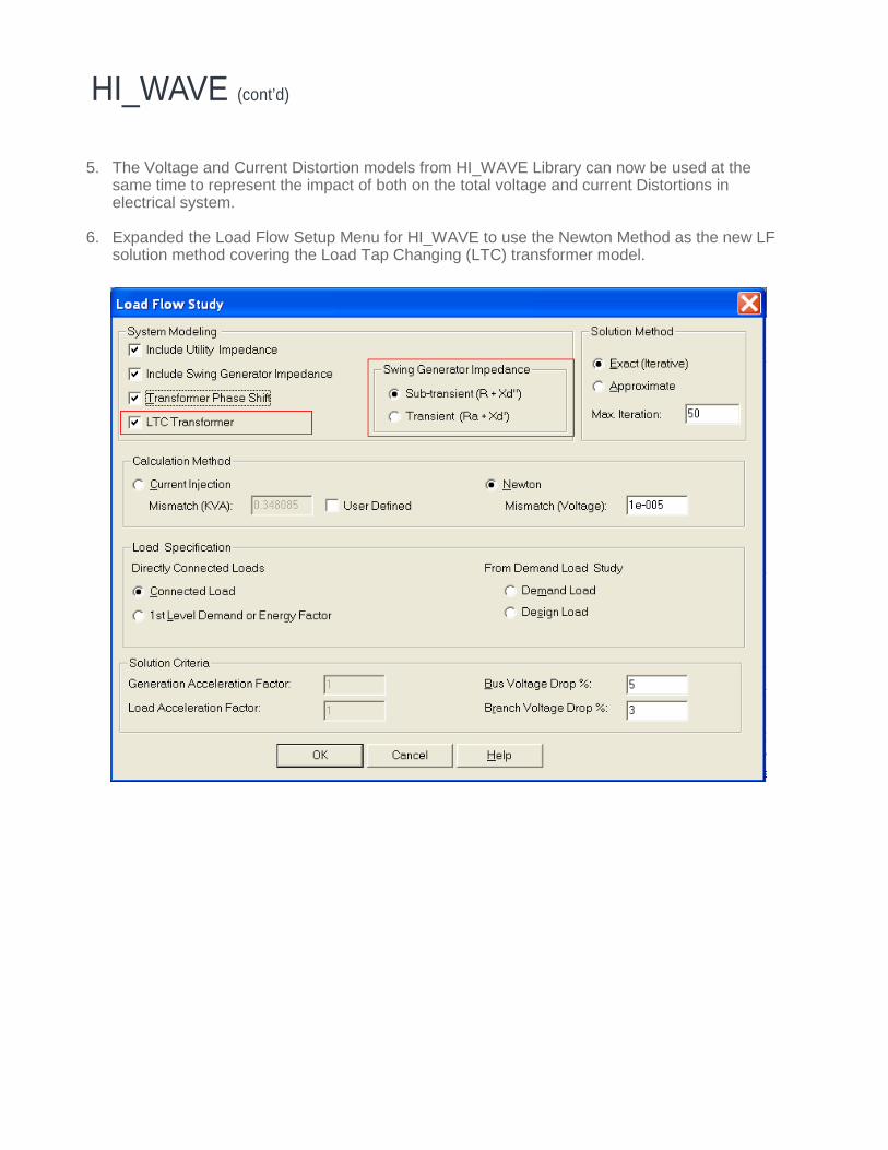
6. Expanded the Load Flow Setup Menu for HI_WAVE to use the Newton Method as the new LF
solution method covering the Load Tap Changing (LTC) transformer model.
INDUSTRIAL SIMULATION (I*SIM)
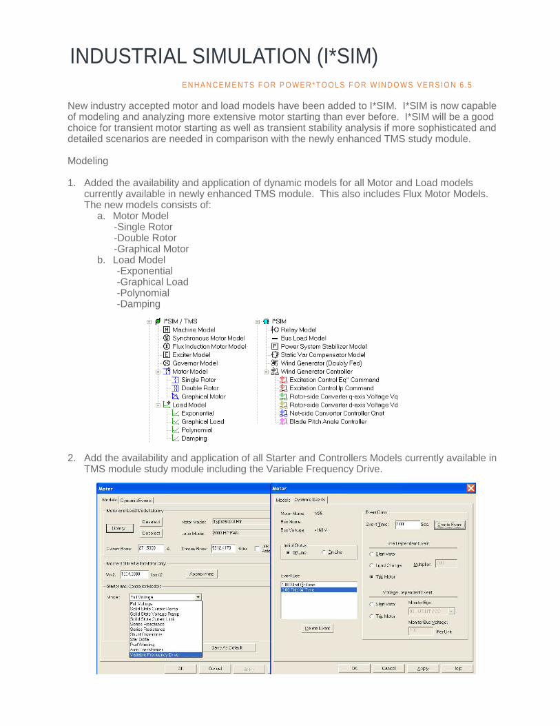
New industry accepted motor and load models have been added to I*SIM. I*SIM is now capable of modeling and analyzing more extensive motor starting than ever before. I*SIM will be a good choice for transient motor starting as well as transient stability analysis if more sophisticated and detailed scenarios are needed in comparison with the newly enhanced TMS study module. Modeling 1. Added the availability and application of dynamic models for all Motor and Load models
currently available in newly enhanced TMS module. This also includes Flux Motor Models. The new models consists of:
a. Motor Model -Single Rotor -Double Rotor -Graphical Motor
b. Load Model -Exponential -Graphical Load -Polynomial -Damping
2. Add the availability and application of all Starter and Controllers Models currently available in TMS module study module including the Variable Frequency Drive.
E N H A N CE M E N TS F O R P O WE R* T O OL S F O R WI N D O WS V E RS I O N 6 .5
INDUSTRIAL SIMULATION (I*SIM) (cont’d)
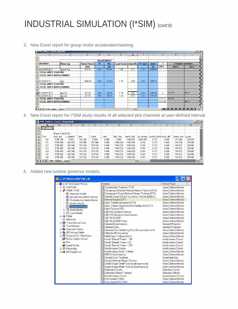
3. New Excel report for group motor acceleration/starting.
4. New Excel report for I*SIM study results of all selected plot channels at user-defined interval.
5. Added new turbine governor models:
UNBALANCED/SINGLE PHASE
1. Datablocks with “UbSC_xxxSimFault” has been renamed and enhanced to the following format: “UbSC_xxx”. For example, "ubSC_InitSymSimFault" to "ubSC_InitSym." The following fields now store the unbalanced SC results based on the last unbalanced short circuit study option that was completed: either a Fault bus by bus or simultaneous faults. This will keep the datablock to a minimum (it is now not necessary to list datablocks for 3P, SLG, LL, LLG, etc. if you are only looking for the results that was previously evaluated).
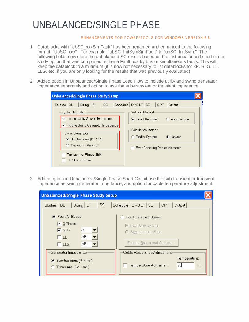
2. Added option in Unbalanced/Single Phase Load Flow to include utility and swing generator
impedance separately and option to use the sub-transient or transient impedance. 3. Added option in Unbalanced/Single Phase Short Circuit use the sub-transient or transient
impedance as swing generator impedance, and option for cable temperature adjustment.
E N H A N CE M E N TS F O R P O WE R* T O OL S F O R WI N D O WS V E RS I O N 6 .5

UNBALANCED/SINGLE PHASE (cont’d)
4. Swing bus definition is no longer required for fault calculations. The generator with the biggest kVA rating as the swing bus will be used to provide fault current calculations.
5. Option to include or exclude Load Flow Current in the Unbalanced/Single Phase Short Circuit. 6. Added option in Unbalanced/Single Phase Schedule to select multiple formats, and to report
each selected format in a different file. 7. Option to report Arc Flash results on the schedule header.

DC SYSTEMS ANALYSIS
1. Added a new Derating Factor field in the Battery Subview of Component Editor to represent the aging factor of the battery capacity. This factor will be multiplied by the Battery Discharge Curve values to give the actual derated Amps and Amp-hours of the battery capacity.
2. The Load Flow Setup menu has a new option for considering the source impedance for
Battery and Swing Generator.
E N H A N CE M E N TS F O R P O WE R* T O OL S F O R WI N D O WS V E RS I O N 6 .5
DC SYSTEMS ANALYSIS (cont’d)
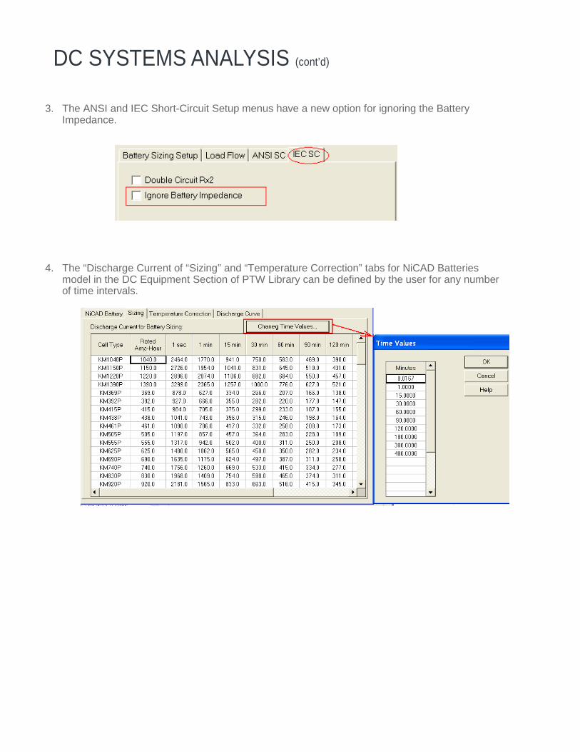
3. The ANSI and IEC Short-Circuit Setup menus have a new option for ignoring the Battery Impedance.
4. The “Discharge Current of “Sizing” and “Temperature Correction” tabs for NiCAD Batteries
model in the DC Equipment Section of PTW Library can be defined by the user for any number of time intervals.

SKM Power*Tools® For Windows
DAPPER® Integrated Electrical Analysis SoftwareComprehensive Three Phase and Unbalanced Short-Circuit Studies, Load Flow Study, Demand Load Study, Feeder andTransformer Sizing Study, Impact Motor Starting Study, and Load Schedules.
CAPTOR® Time-Overcurrent CoordinationGraphical Time-Overcurrent Coordination. Integrated with one-lines, short-circuit modules, Equipment Evaluation, and ArcFlash. Comprehensive protective device library.
ARC FLASH EVALUATION
Calculates the incident energy and arc flash boundary for each bus in the system. Trip times are automatically determined from theprotective device settings and arcing fault current values. Incident energy and arc flash boundaries are calculated based onaccumulated fault values. Clothing requirements are specified from a user-defined clothing library. Clearing times can be reducedbased on current-limiting capabilities. Complies with OSHA, NFPA 70E, NEC 110.16, and IEEE 1584 requirements. Generatescustom labels and work permits. Also available as ArcCalc, a simplified stand-alone Arc Flash calculator.
A_FAULT ANSI Short-Circuit StudyThree Phase and Unbalanced Short-Circuit based on the ANSI/IEEE C37 Standards. Separate solutions for low, medium and highvoltage systems and for symmetrical, momentary and interrupting calculations.
IEC_FAULT IEC Short-Circuit Study 909 or 363Three Phase and Unbalanced Short-Circuit Study based on the IEC 60909 or IEC 61363 Standards.
EQUIPMENT EVALUATION Equipment Evaluation ReportAutomatically compares short-circuit ratings, withstand ratings. Applies de-rating adjustments and user defined pass/marginal/failed criteria. Includes error checking for input data and topology.
IEE WIRING REGULATION SIZING
Integrates the rules and data tables from the IEE Wiring Regulation to size cables based on the design loads of the powersystem. Automatically select the correct table from the IEE Wiring Regulation and pick the proper cable size.
TMS Transient Motor Starting SimulationTime-based motor starting simulation with graphical output. Includes reduced voltage and capacitor starting, graphical motorand load models.
HI_WAVE Harmonic Investigation and Filter DesignFrequency Scan, Harmonic Current, Voltage Distortion, Harmonic Load Flow and Interactive Filter Design.
I*SIM Dynamic Simulation and Transient StabilityDynamic Response to Power System Electro-Mechanical Disturbances, Generator Sizing and Stability, Flux Level MachineRepresentation. User Defined Graphical Models for Exciter, Turbine Governor, PSS, and other controllers.
UNBALANCED/SINGLE PHASE STUDIES
Load flow, short-circuit, demand load analysis, sizing, and load schedules. Reports single-phase loads and unbalanced operatingconditions including phase and sequence currents and voltages.
DISTRIBUTION RELIABILITY Reliability AnalysisCalculates the reliability indices of individual load points and the overall distribution systems with either radial or loop configuration.Includes Load Point MTTF, Failure/Year, MTTR, Annual Outage, EENS, ECOST, and other IEEE indices. Cost-related factors andaging factors are included in the analysis to compare alternative designs.
DC SYSTEMS ANALYSIS
Battery Sizing, Load Flow, & Short Circuit Analysis. Evaluate all loading conditions for DC duty cycle loads and AC emergencyloads. Complies with IEEE std. 485, 1115, 399, 946, and IEC std. 61660.
PTW VIEWER
Read-only version of PTW for displaying, printing, and exporting all study results. Create or expand one-lines and applydatablocks. View Time-Current Curves. View and create customized Arc Flash Labels and Work Permits.
GROUND MAT Substation Ground Grid Design and AnalysisOptimizes grid design using general purpose finite element algorithm for potential analysis and graphical facilities to validategrounding systems efficiency.
CABLE-3D
Solves complex three-dimensional cable pulling tension and sidewall pressure calculations.
Electrical Engineering Software
