kessel - leading in drainage 2 · kessel offers a factory extended guarantee of 20 years on the...
TRANSCRIPT

Separators
PPoollyy
eetthhyy
lleennee WWaarrrraannttyy
202 YeY ars
Wastewater treatment

160 Catalogue 2.3
Gre
as
e s
ep
ara
tors
fo
r in
teri
or
ins
tall
ati
on
G
rea
se
se
pa
rato
rs f
or
un
de
rgro
un
d i
ns
tall
ati
on
Oil
-/F
ue
l-/C
oa
les
ce
nc
e s
ep
ara
tors
............................ 164
............................. 165
........................... 166
................................. 167
..................................... 168
..................................... 169
................... 170
.......................... 172
.......................................... 177
.................. 178
“G” NS 1/2/4
“G” NS 7/10/15/20/25/30/35
........................... 183
........................... 184
.................................... 185
........................ 186
1) Odour emissions shouldbe avoided during grease disposal
2) Grease must beevacuated regularly
Grease separators for free standing installation
For reasons of space, thegrease separator system must be installed outside the building
Grease separators for underground installation
During tank filling, servicingor vehicle cleaning, light liquids occur
Oil-/Fuel separatorsCoalescence separators
“E+S” PV NS 2/4/7/10with program-controlled disposal systemand Shredder-Mix-System
“E+S” M NS 2/4/7/10with manually controlled disposal systemand Shredder-Mix-System
“D+S-P1” NS 2/4/7/10with direct disposal and programcontrolled Shredder-Mix-System
“D+S” NS 2/4/7/10with direct disposal and Shredder-Mix-System
“D” NS 2/4/7/10with direct disposal
“G” NS 2/4/7/10basic-version
“SE-Premium” NS 2/4/7/10for self-disposal
Euro “G” NS 0.25/0.5/1
Coalescence separatorNS 3/6
Coalescence separatorNS 3 - NS 15
Oil/fuel separatorNS 3 - NS 15
Oil/fuel separator NS 1.5

161Catalogue 2.3
Grease separators
PPoollyy
eetthhyy
lleennee WWaarrrraannttyy
202 YeY ars
Gre
as
e s
ep
ara
tors
fo
r in
teri
or
ins
tall
ati
on
G
rea
se
se
pa
rato
rs f
or
un
de
rgro
un
d i
ns
tall
ati
on
Oil
-/F
ue
l-/C
oa
les
ce
nc
e s
ep
ara
tors

162 Catalogue 2.3
Gre
as
e s
ep
ara
tors
fo
r in
teri
or
ins
tall
ati
on
G
rea
se
se
pa
rato
rs f
or
un
de
rgro
un
d i
ns
tall
ati
on
Oil
-/F
ue
l-/C
oa
les
ce
nc
e s
ep
ara
tors
Po lyethylene Grease Separators - the corrosion free al ternat ive
Polyethylene has proven to be the material of choice for themanufacture of above ground and underground grease separa-tors. The German DIBT (German Institute for StructuralEngineering) has granted the KESSEL grease separators theDIBT certification making KESSEL the first manufacturer on theGerman market to be granted such a certification.
Polyethylene grease separators offer significant advantages
for engineers, architects, installation companies as well as
building owners and operators. The fully watertight bodies
are also fracture resistant meaning ultra-long life expec-
tancy.
KESSEL offers a factory extended guarantee of 20 years on
the polyethylene grease separator tanks -
this covers the structural integrity,
watertightness and usability of the
polyethylene components.
Odour tight
Of utmost importance for a grease separator is that fact that thesystem is odour tight. KESSEL separators offer monolythic / onepiece construction meaning no seams or welds are used inmanufacturing of the separators. The separator bodies are leakproof and odour tight as well as the gasketed access covers ofthe separators.
Resistant to aggressive grease and wastewater
The polyethylene separator material guarantees an extremelylong service life due to its corrosion free properties.
Compact design, low weight
Minimum separator body dimensions meaneasy access through existing stairwells anddoorways and minimum required space forinstallation
Poly
et
hylene Warranty
Poly
et
hylene Warranty
20 Years
- Professional advantages
Fully automated operationOdour free disposal and cleaningMixing of separator contentswith Shredder-Mix-SystemOptimal cleaning with only a single pumpOptional remote control
Grease Separator “E+S” PV
Odour free disposal and cleaningMixing of separator contentswith Shredder-Mix-SystemComplete cleaningof interior separator wallsDisposal through pre-installeddisposal pipe by pumpSimple On / Off controlManual change-over from mixingto disposal
Grease Separator “E+S” M
Odour free disposal and cleaningMixing of separator contentswith Shredder-Mix-System Simple controlsNo warm water connection necessaryDisposal through pre-installed disposal pipeFully automated operation exceptfor disposal (version “D+S-P1” )
Grease Separator “D+S /D+S-P1”
Products - see pages 166/167 Product - see page 165Product - see page 164
Easy to clean
Crust formation on the walls is prevented by thesurface finish, which is similar to wax. The systemis easy to clean, leading to shorter disposal timesand lower cleaning water consumption.

163Catalogue 2.3
Gre
as
e s
ep
ara
tors
fo
r in
teri
or
ins
tall
ati
on
G
rea
se
se
pa
rato
rs f
or
un
de
rgro
un
d i
ns
tall
ati
on
Oil
-/F
ue
l-/C
oa
les
ce
nc
e s
ep
ara
tors
Easy transport
Their low weight allows KESSEL greaseseparators to be transported easily. Thespecial base structure of the separatorsallows problem-free transport by meansof a forklift.
Telescopic upper section is standard
For underground installation, the upper sectioncan be vertically adjusted by up to 500 mm andtilted through up to 5° for adaptation to theground level. The odour-proof covers are availa-ble in the load classes A/B, D.
Absolutely tight
PE-HD is absolutely waterproof. The individualelements and pipe connections are sealed usingsealing rings according to EN 681-1 which sealboth axially and radially, thus guaranteeing ahigh degree of safety.
Grease separators made of polymer
Closed cover disposalOdour free disposal possiblewith non-solidified greasesCleaning possible with open coversDisposal through pre-installed disposal pipe
Grease Separator “D”
for free standing or underground installation
Open cover disposalLow cost modelNS 2 to NS 35Disposal with open coversDisposal system available upon request
Grease Separator “G”
Regular disposal of grease and sludgeeven during separator operationSeparate disposal of grease and sludgeEnvironmentally friendly recyclingof collected wasteDisposal costs reduced since cleanwater remains in separator, only greaseand sludge are removedDisposal requires no additional water forrinsing, cleaning or re-filling which savesvaluable drinking waterOn-site assembly available
Grease Separator “SE”
Product - see page 170Products - see pages 169 / 177 - 178Product - see page 168
SonicControl level sensing system with ultra sonic sensor
for the measurement, display and control of the grease layer thickness in a grease separator
Disposal costs are saved
by extending the disposal intervals.
Environment protection
Disposal of clean water no longer necessary,takes the pressure off resources.
User-friendly operation
thanks to the interactive control unit with digitaldisplay and userfriendly interface.
Products - see page 173

Dimensioned illustration
Ø = Inlet and outlet outer diameter (mm) b1 = Installation dimensions
Ø
110110160160
a
1030150016002430
b
670730990990
h1
930930
11301130
h2
1000100012001200
h3
1310131015601560
l
1250181018502700
Sludge trap
200 l400 l700 l
1000 l
Wastewater content
Separator
212 l354 l567 l794 l
Grease
storage
106 l177 l302 l423 l
Nominal size
NS 2NS 4NS 7NS 10
b1
1050105012201220
x
Access opening
Article descriptionIllustration
KESSEL Euro “E+S” PV Grease Separator according to Euro Norm EN 1825 NS 2/4/7/10with Shredder-Mix-System and fully automated disposal, cleaning and refilling program for free standing installation in frost protected areas
Nominal size* Article #
NS 2NS 4NS 7NS 10
150 kg165 kg200 kg225 kg* other sizes available on request
for free standing installation in frost free areas
System delivered completely assembled
Installation site
93 002.50 / P193 004.50 / P193 007.50 / P193 010.50 / P1
93 002.00 / P193 004.00 / P193 007.00 / P193 010.00 / P1
Pump left Pump right
Pump size
3.0 kW3.0 kW3.0 kW3.0 kW
Weight empty
Oil
-/F
ue
l-/C
oa
les
ce
nc
e s
ep
ara
tors
Gre
as
e s
ep
ara
tors
fo
r u
nd
erg
rou
nd
in
sta
lla
tio
nG
rea
se
se
pa
rato
rs f
or
inte
rio
r in
sta
lla
tio
n
Catalogue 2.3164
2468
10121416
10 20 30 405 15 25 35 5045 55
3,0 kW
[Qm3/h]
[m]
Grease separator (Art. # 93 004.00 / P1)
Sampling chamer (Art. # 915 870)
Lifting station (Art. # 28 766)
�420l
a
h2 h1h3
bb1
�
KESSEL Euro “E+S” PV Grease Separator Manufactured from virgin, non-recycled polyethylene.
For free standing installation in frost protected areas, withintegrated sludge trap, inlet flow calming system and outletflow regulation device, twin access covers with quick releaseodour tight snap closures, inspection window with interiorcleaning arm on left or right side, PV version fully automatedodour free disposal, cleaning and refilling system at touch ofbutton, maintenance free macerating motor (stainless steelblades) for separator cleaning and disposal, includes closurevalve for easy motor removal, motor floor mount included withinstallation hardware and anti-vibration matt, actuator valvefor automated transfer from cleaning to disposal mode, topmounted water jet(s) for grease layer breakup and water spraynozzles for interior wall cleaning during disposal, with LCDdisplay control unit settable in English, German or Frenchlanguage and mains power safety on/off switch, with BMSconnections, twin 1 inch solenoid valves for connection of coldand hot water pipes to separator, 1 inch interior threaded refillinlet with air gap, 65 mm OD PN 10 pressure disposal pipewith flange according to DIN 2501, with 2.5 inch ‘Storz-B’connection coupling for disposal trucks, integrated fork lift grips at base of separator, low weight - compact design,100% corrosion free polyethylene body construction (20 year warranty).
Choose separator size and article number from table below. Contact KESSEL for separator sizing support if required. Grease Separator Article Number - ..........
Accessories Page 173 - 176
Motor specifications:3.0 kW – 400 V, 50 Hz, IP 54, pumps 47 m3/hour at 0.7 bar, precision cast iron body
European Norm 1825 Certification Number: Z-54.1-474

KESSEL Euro “E+S” M Grease Separator according to Euro Norm EN 1825 NS 2/4/7/10with Shredder-Mix-System and manually controlled disposal, cleaning and refilling programfor free standing installation in frost protected areas
Article descriptionIllustration
bb1
Ø420l
a
h2 h1h3
Ø
Dimensioned illustration
Nominal size* Article #
NS 2NS 4NS 7NS 10
140 kg155 kg190 kg215 kg* other sizes available on request
for free standing installation in frost free areas
System delivered completely assembled
Installation site
93 002.50/ M193 004.50/ M193 007.50/ M193 010.50/ M1
93 002.00 / M193 004.00 / M193 007.00 / M193 010.00 / M1
Pump left Pump right
Pump size
Ø = Inlet and outlet outer diameter (mm) b1 = Installation dimensions
3.0 kW3.0 kW3.0 kW3.0 kW
Ø
110110160160
a
1030150016002430
b
670730990990
h1
930930
11301130
h2
1000100012001200
h3
1310131015601560
l
1250181018502700
Sludge trap
200 l400 l700 l
1000 l
Wastewater content
Separator
212 l354 l567 l794 l
Grease
storage
106 l177 l302 l423 l
Nominal size
NS 2NS 4NS 7NS 10
b1
1050105012201220
x
Access opening
Weight empty
Oil
-/F
ue
l-/C
oa
les
ce
nc
e s
ep
ara
tors
Gre
as
e s
ep
ara
tors
fo
r u
nd
erg
rou
nd
in
sta
lla
tio
nG
rea
se
se
pa
rato
rs f
or
inte
rio
r in
sta
lla
tio
n
Catalogue 2.3 165
2468
10121416
10 20 30 405 15 25 35 5045 55
3,0 kW
[Qm3/h]
[m]
Grease separator (Art. # 93 004.00 / M1)
Sampling chamer (Art. # 915 870)
Lifting station (Art. # 28 766)
KESSEL Euro “E+S” M Grease Separator Manufactured from virgin, non-recycled polyethylene.
For free standing installation in frost protected areas, withintegrated sludge trap, inlet flow calming system and outletflow regulation device, twin access covers with quick releaseodour tight snap closures, inspection window with interiorcleaning arm on left or right side, M version manually con-trolled odour free disposal, cleaning and refilling system attouch of button, maintenance free macerating motor (stainlesssteel blades) for separator cleaning and disposal, includesclosure valve for easy motor removal, motor floor mountincluded with installation hardware and anti-vibration matt,manual hand valve for transfer from cleaning to disposalmode, top mounted water jet(s) for grease layer breakup andwater spray nozzles for interior wall cleaning during disposal,with control unit and mains power safety on/off switch, withBMS connections, twin 1 inch solenoid valves for connectionof cold and hot water pipes to separator, 1 inch interior threa-ded refill inlet with air gap, 65 mm OD PN 10 pressure dispo-sal pipe with flange according to DIN 2501, with 2.5 inch‘Storz-B’ connection coupling for disposal trucks, integratedfork lift grips at base of separator, low weight - compactdesign, 100% corrosion free polyethylene body construction(20 year warranty).
Choose separator size and article number from table below. Contact KESSEL for separator sizing support if required. Grease Separator Article Number - ..........
Accessories Page 173 - 176
Motor specifications:3.0 kW – 400 V, 50 Hz, IP 54, pumps 47 m3/hour at 0.7 bar, precision cast iron body
European Norm 1825 Certification Number: Z-54.1-474

Article descriptionIllustration
KESSEL Euro “D+S-P1” Grease Separator according to Euro Norm EN 1825 NS 2/4/7/10with program controlled Shredder-Mix-System, cleaning and refilling program for free standing installation in frost protected areas
Dimensioned illustration
Nominal size* Article #
NS 2NS 4NS 7NS 10
140 kg155 kg190 kg215 kg* other sizes available on request
for free standing installation in frost free areas
System delivered completely assembled
Installation site
93 002.50/DS-P193 004.50/DS-P193 007.50/DS-P193 010.50/DS-P1
93 002.00/DS-P193 004.00/DS-P193 007.00/DS-P193 010.00/DS-P1
left rightDisposal pipe connection
Scope of delivery
Container with 2 domedcovers, internal and externalpiping complete with disposalpipe connection, Shredder-Mix-System with on/offswitch, inlet
Ø
110110160160
a
1030150016002430
b
670730990990
b1
1050105012201220
h1
930930
11301130
h2
1000100012001200
h3
1310131015601560
Sludge trap
200 l400 l700 l
1000 l
Wastewater content
Separator
212 l354 l567 l794 l
Grease
storage
106 l177 l302 l423 l
Nominal size
NS 2**NS 4NS 7NS 10
Access opening
l
1250181018502700
x
Ø = Inlet and outlet outer diameter (mm) b1 = Installation dimensions
bb1
�420l
a
h2 h1h3
�
�
** Please note: In the case of NS 2 the disposal pipe must be attached to the side opposite the pump.
Weight empty
KESSEL Euro “D+S-P1” Grease Separator Manufactured from virgin, non-recycled polyethylene.
For free standing installation in frost protected areas, withintegrated sludge trap, inlet flow calming system and outletflow regulation device, twin access covers with quick releaseodour tight snap closures, D+S-P1 version with simultaneousmixing and cleaning of separator interior – requires disposaltruck with vacuum system for separator disposal, disposal iscompletely odour free, maintenance free macerating motor(stainless steel blades) includes closure valve for easy motorremoval, motor floor mount included with installation hard-ware and anti-vibration matt, top mounted water jet(s) forgrease layer breakup and water spray nozzles for interior wallcleaning during disposal, 1 inch interior thread refill inlet withair gap, with LCD display control unit settable in English,German or French language and mains power safety on/offswitch, with BMS connections, with remote control offering fullseparator disposal control from remote location (from disposaltruck location), 65 mm OD PN 10 pressure disposal pipe withflange according to DIN 2501, with 2.5 inch ‘Storz-B’ connec-tion coupling for disposal trucks, integrated fork lift grips atbase of separator, low weight - compact design, 100% corro-sion free polyethylene body construction (20 year warranty).
Motor specifications: 3.0 kW – 400 V, 50 Hz, IP 54Choose separator size and article number from table below. Contact KESSEL for separator sizing support if required. Grease Separator Article Number - ..........
Accessories Page 173 - 176
166 Catalogue 2.3
Gre
as
e s
ep
ara
tors
fo
r in
teri
or
ins
tall
ati
on
G
rea
se
se
pa
rato
rs f
or
un
de
rgro
un
d i
ns
tall
ati
on
Oil
-/F
ue
l-/C
oa
les
ce
nc
e s
ep
ara
tors
� �
Grease separator (Art. # 93 004.00 / DS-P1)
Sampling chamer (Art. # 915 870)
Lifting station (Art. # 28 766)
European Norm 1825 Certification Number: Z-54.1-474

Article descriptionIllustration
KESSEL Euro “D+S” Grease Separator according to Euro Norm EN 1825 NS 2/4/7/10with Shredder-Mix-System cleaning and refilling program for free standing installation in frost protected areas
Dimensioned illustration
Nominal size* Article #
NS 2NS 4NS 7NS 10
130 kg140 kg170 kg215 kg* other sizes available on request
for free standing installation in frost free areas
System delivered completely assembled
Installation site
93 002.50 / DS193 004.50 / DS193 007.50 / DS193 010.50 / DS1
93 002.00 / DS193 004.00 / DS193 007.00 / DS193 010.00 / DS1
left rightDisposal pipe connection
Scope of delivery
Container with 2 domedcovers, internal and externalpiping complete with disposalpipe connection, Shredder-Mix-System with on/offswitch, inlet
Ø
110110160160
a
1030150016002430
b
670730990990
b1
1050105012201220
h1
930930
11301130
h2
1000100012001200
h3
1310131015601560
Sludge trap
200 l400 l700 l
1000 l
Wastewater content
Separator
212 l354 l567 l794 l
Grease
storage
106 l177 l302 l423 l
Nominal size
NS 2**NS 4NS 7NS 10
Access opening
l
1250181018502700
x
Ø = Inlet and outlet outer diameter (mm) b1 = Installation dimensions
bb1
�420l
a
h2 h1h3
�
�
** Please note: In the case of NS 2 the disposal pipe must be attached to the side opposite the pump.
Weight empty
167Catalogue 2.3
Gre
as
e s
ep
ara
tors
fo
r in
teri
or
ins
tall
ati
on
G
rea
se
se
pa
rato
rs f
or
un
de
rgro
un
d i
ns
tall
ati
on
Oil
-/F
ue
l-/C
oa
les
ce
nc
e s
ep
ara
tors
� �
Grease separator (Art. # 93 004.00 / DS1)
Sampling chamer (Art. # 915 870)
Lifting station (Art. # 28 766)
KESSEL Euro “D+S” Grease Separator Manufactured from virgin, non-recycled polyethylene.
For free standing installation in frost protected areas, withintegrated sludge trap, inlet flow calming system and outletflow regulation device, twin access covers with quick releaseodour tight snap closures, D+S version with simultaneousmixing and cleaning of separator interior – requires disposaltruck with vacuum system for separator disposal, disposal iscompletely odour free, maintenance free macerating motor(stainless steel blades) includes closure valve for easy motorremoval, motor floor mount included with installation hard-ware and anti-vibration matt, top mounted water jet(s) forgrease layer breakup and water spray nozzles for interior wallcleaning during disposal, 1 inch interior thread refill inlet withair gap, with hand held operation controller, 65 mm OD PN 10pressure disposal pipe with flange according to DIN 2501, with 2.5 inch ‘Storz-B’ connection coupling for disposaltrucks, integrated fork lift grips at base of separator, lowweight - compact design, 100% corrosion free polyethylenebody construction (20 year warranty).
Motor specifications: 3.0 kW – 400 V, 50 Hz, IP 54Choose separator size and article number from table below. Contact KESSEL for separator sizing support if required. Grease Separator Article Number - ..........
Accessories Page 173 - 176
European Norm 1825 Certification Number: Z-54.1-474

KESSEL Euro “D” Grease Separator according to Euro Norm EN 1825 NS 2/4/7/10with direct disposal for free standing installation in frost protected areas
Article descriptionIllustration
Nominal size*Article #
Disposal pipe connection
NS 2NS 4NS 7NS 10
54 kg69 kg
104 kg129 kg* other sizes available on request
for free standing installation in frost free areas
System delivered completely assembled
Dimensioned illustration
Installation site
b
b1
� �
Ø
110110160160
a
1030150016002430
b
670730990990
b1
780810
10801080
h1
930930
11301130
h2
1000100012001200
h3
1310131015601560
l
1250181018502700
Sludge trap
200 l400 l700 l
1000 l
Wastewater content
Separator
212 l354 l567 l794 l
Grease
storage
106 l177 l302 l423 l
Nominal size
NS 2NS 4NS 7NS 10
93 002.00 / D193 004.00 / D193 007.00 / D193 010.00 / D1
93 002.50 / D193 004.50 / D193 007.50 / D193 010.50 / D1
rightleft
Scope of delivery
Container with domed covers,piping complete with disposalpipe connection
Ø = Inlet and outlet outer diameter (mm) b1 = Installation dimensions
420
h2 h1h3
l
a
�
x
Access opening
KESSEL Euro “D” Grease Separator Manufactured from virgin, non-recycled polyethylene.
For free standing installation in frost protected areas, with integrated sludge trap, inlet flow calming system andoutlet flow regulation device, twin access covers with quickrelease odour tight snap closures, D version with factoryinstalled pressure pipe suction outlet – requires disposaltruck with vacuum system for separator disposal, disposal is completely odour free, 65 mm OD PN 10 pressure disposalpipe with flange according to DIN 2501, with 2.5 inch ‘Storz-B’ connection coupling for disposal trucks, integratedfork lift grips at base of separator, low weight - compactdesign, 100% corrosion free polyethylene body construction (20 year warranty).
Choose separator size and article number from table below. Contact KESSEL for separator sizing support if required. Grease Separator Article Number - ..........
Accessories Page 173 - 176
Weight empty
Oil
-/F
ue
l-/C
oa
les
ce
nc
e s
ep
ara
tors
Gre
as
e s
ep
ara
tors
fo
r u
nd
erg
rou
nd
in
sta
lla
tio
nG
rea
se
se
pa
rato
rs f
or
inte
rio
r in
sta
lla
tio
n
Catalogue 2.3168
Grease separator (Art. # 93 004.00 / D1)
Sampling chamer (Art. # 915 870)
Lifting station (Art. # 28 766)
European Norm 1825 Certification Number: Z-54.1-474

Oil
-/F
ue
l-/C
oa
les
ce
nc
e s
ep
ara
tors
Gre
as
e s
ep
ara
tors
fo
r u
nd
erg
rou
nd
in
sta
lla
tio
nG
rea
se
se
pa
rato
rs f
or
inte
rio
r in
sta
lla
tio
n
Catalogue 2.3 169
Dimensioned illustration
Article descriptionIllustration
KESSEL Euro “G” Grease Separator according to Euro Norm EN 1825 NS 2/4/7/10for free standing installation in frost protected areas
Nominal size* Scope of deliveryArticle #
NS 2NS 4NS 7NS 10
50 kg65 kg
100 kg125 kg
93 00293 00493 00793 010
for free standing installation in frost free areas
System delivered completely assembled
Container with domed coversand snap closures
Installation site
��
b
Ø
110110160160
a
1030150016002430
b
670730990990
h1
930930
11301130
h2
1000100012001200
h3
1310131015601560
l
1250181018502700
x Sludge trap
200 l400 l700 l
1000 l
Wastewater contentAccess opening
Separator
212 l354 l567 l794 l
Grease
storage
106 l177 l302 l423 l
Nominal size
NS 2NS 4NS 7NS 10
Ø = Inlet and outlet outer diameter (mm)
420
h1h3
h2
a
* Other sizes available on request
Weight empty
KESSEL Euro “G” Grease Separator Manufactured from virgin, non-recycled polyethylene.
For free standing installation in frost protected areas, withintegrated sludge trap, inlet flow calming system and outletflow regulation device, twin access covers with quick releaseodour tight snap closures, G version requires disposal truckwith vacuum system for separator disposal, integrated forklift grips at base of separator, 100% corrosion free polyethy-lene body construction (20 year warranty).
Choose separator size and article number from table below. Contact KESSEL for separator sizing support if required. Grease Separator Article Number - ..........
Accessories Page 173 - 176
Grease separator (Art. # 93 004)
Sampling chamer (Art. # 915 870)
Lifting station (Art. # 28 766)
European Norm 1825 Certification Number: Z-54.1-474

170 Catalogue 2.3
Gre
as
e s
ep
ara
tors
fo
r in
teri
or
ins
tall
ati
on
G
rea
se
se
pa
rato
rs f
or
un
de
rgro
un
d i
ns
tall
ati
on
Oil
-/F
ue
l-/C
oa
les
ce
nc
e s
ep
ara
tors
Article descriptionIllustration
KESSEL “SE Premium” Grease Separator according to Euro Norm 1825 NS 2/4/7/10 for self disposal
for free standing installation in frost free areas
KESSEL “SE Premium” Grease Separator NS … Separator that complies to CJ/T 295-2008 / EN 1825 / DIN 4040, made of polyethylene PE-HD For free standing installation in frost-free rooms, withupstream sludge trap, quick release and odour-tight remove-able access covers, separator chamber with heated lid coverscrewed tight to prevent odours escaping. Inlet and outletsØ ... for SML-connection in compliance with DIN 19522. With self-disposal device for separated floating, settlingsludge and grease removal via manual taps. Visual control of disposal with see-thru disposal hoses, disposal possibleduring separtor operation. Each with a grease, scum andsediment disposal bucket with an adapter lid and a sparebucket. System with an external pump for removing the sedimentfrom the grease separation chamber (230 V, 50 Hz, 750 W),electrical heating (230 V, 50 Hz, 1200 W) for grease collect-ion chamber and motor-driven mixer (230 V, 50 Hz, 360 W)and control unit (230 V, 50 Hz, 6,3 - 10 A), general systemprotection class IP 54
Accessories Page 173 - 176
Dimensioned illustration “SE Premium” NS 2, NS 4, NS 7, NS 10
Nominal size Article #
NS 2NS 4NS 7NS 10
empty260 kg290 kg400 kg450 kg
full1460 kg1490 kg2100 kg2520 kg
99 002.0199 004.0199 007.0199 010.01
for free standing installation in frost free areas
Other sizes available upon request (see page 208).
Installation site Scope of delivery
System completely assembled
Ø(mm)
110110160160
Nominal size
NS 2NS 4NS 7NS 10
Ø = Inlet and outlet outer diameter (mm)
Weight in kg
1920195021392139
3286331635313831
2971302132733577
1351135115191519
1585158516801680
1655165517501750
610610670670
H *(mm)
L(mm)
l(mm)
B(mm)
h1(mm)
h2(mm)
Largest componenth b
Grease separator (Art. # 99 007.01)
Sampling chamber (Art. # 915 870)
Lifting station (Art. # 28 766)
1012106212981298
* Please note that additional space above the separator is required for service / maintenance purposes (at least 50 cm is recommended)
L
l
h1h2H
h
��
b
B

171Catalogue 2.3
Gre
as
e s
ep
ara
tors
fo
r in
teri
or
ins
tall
ati
on
G
rea
se
se
pa
rato
rs f
or
un
de
rgro
un
d i
ns
tall
ati
on
Oil
-/F
ue
l-/C
oa
les
ce
nc
e s
ep
ara
tors
KESSEL “SE Premium” Grease Separator according to Euro Norm 1825 NS 2/4/7/10 for self disposal
for free standing installation in frost free areas
KESSEL - Professional advantages
Separator function
Self disposal grease separatorNo disposal truck required. Disposal of waste into standardized 60 liter storage tanks.
Simple and fast installationThanks to the low weight and straightforward KESSEL fastening technology, the KESSEL round-designgrease separator system can easily be dismantled to minimum component size, allowing it to be set up in rooms with only very narrow access.
Multiple set-up optionsNewly designed separators offer multiple set-up options for easy on-site installation. Each separatorcan be custom assembled on-site to best match on-site room requirements (for example for wallinstallation - 180 degree assembly, interior corners - 90 degree assembly or exterior corners - 270 degree assembly).
Now available with Micro-Bubble optionKESSEL SE grease separators now available with Micro-Bubble option. Automated compressorinjects micro air bubbles into separator tank for high efficiency grease separation.
Floating and settling sludge disposal included.
Grease separator can remain in operation during disposal (no operational interruptions).
Inlet
Floating sludge disposal
Settling sludge disposal
Balance tower / Ventilation
Heating dome with mixing motor
Grease disposal
Rinsing pump
Control unit
Outlet
172 Catalogue 2.3
Gre
as
e s
ep
ara
tors
fo
r in
teri
or
ins
tall
ati
on
G
rea
se
se
pa
rato
rs f
or
un
de
rgro
un
d i
ns
tall
ati
on
Oil
-/F
ue
l-/C
oa
les
ce
nc
e s
ep
ara
tors
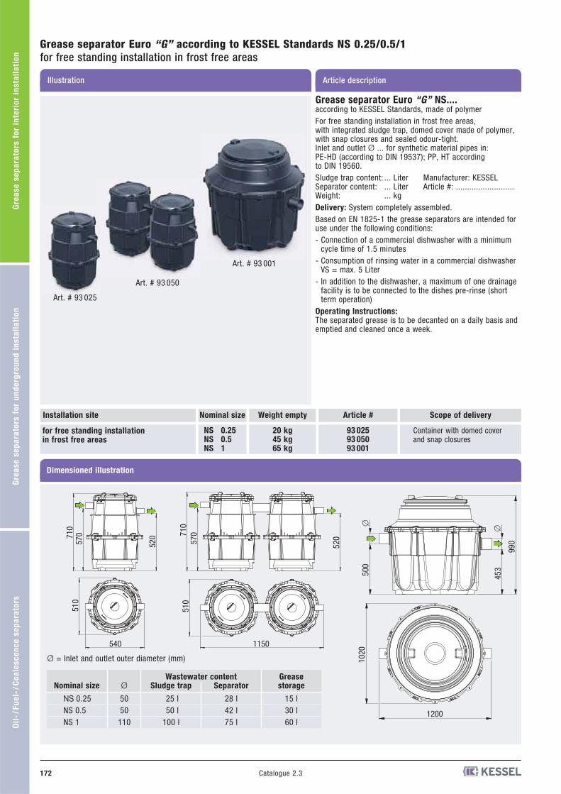
Grease separator Euro “G” according to KESSEL Standards NS 0.25/0.5/1for free standing installation in frost free areas
Article descriptionIllustration
Grease separator Euro “G” NS....according to KESSEL Standards, made of polymerFor free standing installation in frost free areas,with integrated sludge trap, domed cover made of polymer,with snap closures and sealed odour-tight.Inlet and outlet Ø ... for synthetic material pipes in: PE-HD (according to DIN 19537); PP, HT according to DIN 19560.Sludge trap content: ... Liter Manufacturer: KESSELSeparator content: ... Liter Article #: ..........................Weight: ... kgDelivery: System completely assembled.Based on EN 1825-1 the grease separators are intended foruse under the following conditions:- Connection of a commercial dishwasher with a minimum
cycle time of 1.5 minutes- Consumption of rinsing water in a commercial dishwasher
VS = max. 5 Liter- In addition to the dishwasher, a maximum of one drainage
facility is to be connected to the dishes pre-rinse (shortterm operation)
Operating Instructions:The separated grease is to be decanted on a daily basis andemptied and cleaned once a week.
Art. # 93 025
Art. # 93 050
Art. # 93 001
Nominal size Scope of deliveryArticle #
NS 0.25NS 0.5NS 1
20 kg45 kg65 kg
93 02593 05093 001
for free standing installation in frost free areas
Container with domed cover and snap closures
Dimensioned illustration
Installation site
Ø
5050
110
Sludge trap
25 l50 l
100 l
Separator
28 l42 l75 l
Grease storage
15 l30 l60 l
Nominal size
NS 0.25NS 0.5NS 1
Ø = Inlet and outlet outer diameter (mm)
710
570
520
510
540
710
570
520
510
1150
1200
1020
453500
990
�
�
Wastewater content
Weight empty

173Catalogue 2.3
Gre
as
e s
ep
ara
tors
fo
r in
teri
or
ins
tall
ati
on
G
rea
se
se
pa
rato
rs f
or
un
de
rgro
un
d i
ns
tall
ati
on
Oil
-/F
ue
l-/C
oa
les
ce
nc
e s
ep
ara
tors
Article descriptionIllustration and dimensioned drawing
AccessoriesSeparator according to EN 1825 for free standing installation
Refill inlet made of polymer for separation systems
according to DIN 1988, for connection to filling and rinsing connectioncouplings of the separation systems, with two pipe clamps and attach-ment element together with pipe sealing gasket Ø 63.
Model
left 1 inchright 1 inch
Article #
915 800
915 801
Model
Outlet vertical
Article #
915 870
Sampling chamber Ø 400 made of polymer for separation systems
For connection to outlet pipe of separator. Inlet and outlet Ø 110/160 available options for synthetic material pipes in:PE-HD (according to DIN 19537); PVC-HT, PP or AS.Cover sealed odour-tight with snap closure.Manufacturer: KESSEL
Sampling chamber Ø 400 made of polymer for separation systems
For connection to outlet pipe of separator. Inlet and outlet Ø 110/160 available options for synthetic material pipes in:PE-HD (according to DIN 19537); PVC-HT, PP or AS, drop height 120 mm.Cover sealed odour-tight with snap closure.Manufacturer: KESSEL
Model
Outlet horizontal
Article #
915 871
Inspection window for separation systems
Fits KESSEL Separation systems for free standing installation.In flow direction left or right with cleaning system.
Can only be retrofitted by KESSEL Customer Service (on request).
Model
in flow direction left
in flow direction right
Article #
917 770
917 771
154
48
308
R154
Article #
917 821
SonicControl level sensing systemwith ultra sonic sensor for grease separators
Accurate monitoring and data transfer of grease levels. 230 V - 50 Hz power connection. With battery back up, connection forremote speaker.Insallation set with easy assembly and maintenance. For use on aboveground or below ground separators. For retrofit use on existing separators.Control unit with optical and audible alarm with potential free contact.Electronic log book with 12 month capacity. Data transfer by telemetry.
Voltage: 230 V ~ 50 Hz Protection: IP 54Plug: Schuko 1.5 mCable length: 10 m (extendable on-site to 30 meters)
75055012
0
410
� 1
10�
160
� 1
10
� 1
60
580490
� 110
300
590
� 1
10�
160
� 160
344
900
304
�63
1 inch threaded connection

Article descriptionIllustration and dimensioned drawing
AccessoriesSeparator according to EN 1825 for free standing installation
Article #
917 414
Article #
917 413
Stainless steel access panel
For recessed wall installationwith Storz-B disposal pipe hook up connection and remote control connection for use with fully automated grease separators. Remote control not included.Dimensions: 640 x 440 x 160 mm (Width x Height x Depth)Model: “Recessed”, 2 doors, lockable
Stainless steel access panel
For wall installationwith Storz-B disposal pipe hook-up connection and remote control connection for use with fully automated grease separators.Remote control not included.Dimensions: 600 x 400 x 160 mm (Width x Height x Depth)Model: “Wall installation”, 2 doors, lockable
640600
440
400
160
Remote Control mounting area
Storz-B-Coupling connection
600
400
160
Remote Control mounting area
Storz-B-Coupling connection
Oil
-/F
ue
l-/C
oa
les
ce
nc
e s
ep
ara
tors
Gre
as
e s
ep
ara
tors
fo
r u
nd
erg
rou
nd
in
sta
lla
tio
nG
rea
se
se
pa
rato
rs f
or
inte
rio
r in
sta
lla
tio
n
Catalogue 2.3174
Model
-
Article #
916 601
Remote control
Fits KESSEL Separation systems for free standing installationModel “E+S” program-controlled, fully automated according to EN 1825.Cable length 15 m.Plug: Schuko 1.5 m

Oil
-/F
ue
l-/C
oa
les
ce
nc
e s
ep
ara
tors
Gre
as
e s
ep
ara
tors
fo
r u
nd
erg
rou
nd
in
sta
lla
tio
nG
rea
se
se
pa
rato
rs f
or
inte
rio
r in
sta
lla
tio
n
Catalogue 2.3 175
Article # Ø*Article descriptionIllustration and dimensioned drawing
Twin pump lifting station
made of polymer for free-standing installation
With twin removable pumps, integrated backwater flap, Pressure diaphragm control. Inlet Ø 110, ventilation connection Ø 75 (incl. pipe sealing gasket), control with potential free contact.Pressure connection: 11/2 inch outer thread or pressure pipe Ø 40 mm for PVC glued connection.Inlet height: 530 mmTotal height: 720 mm, Ø 500 mmVoltage: 230 V ~ 50 HzMax. chamber size: 55 lmax. pumping height: 8 mIntake power: 2 x 0.48 kWPower cable: 5 mWeight: ca. 25 kg
Ø 40 28 541
AccessoriesSeparator according to EN 1825 for free standing installation
* Ø = Outer Diameter
guaranteed with
tested quality
Type-testedand monitored
LGA Certification: Z-53.3-310EN 12050-2500
Ø 110
530
Ø 4
025
857
5 720
Optional:Potential-free contact and audible alarm page 68
Ecolift backwater lifting station for pipes with natural gradient to the sewer
The alternative to a standard lifting station
For wastewater with or without sewage, for installation in an exposed wastewater pipe
With protective cover. With integrated pump andmotorized backwater flap. During normal conditions, the pipe cross section is open, in the caseof backwater the valve is closed and locked completelyautomatically. During the backwater period, soiledwater is drained using a pump with macerating (cut-ting) device, via a pressure pipe over the backwaterlevel. Plug-in control and warning unit with display,self-diagnosis system (SDS) and battery buffering formaximum safety, with logbook (diary function) for reading the past operating conditions.
Power cable / cable length: 5 mMains voltage/frequency: 230 V AC / 50 HzProtective rating: IP 54 (switch unit)Protective rating: IP 68 (motor)
Ø 110 L: 642 mm H: 405 mmØ 125 L: 645 mm H: 405 mmØ 160 L: 656 mm H: 405 mmØ 200 L: 720 mm H: 405 mm
21 100
21 125
21 150
21 200
Ø 110
Ø 125
Ø 160
Ø 200
9
H
Ø
L
Ø 40
Certification: Z-53.2-487
Further information: See page 36
12345
76
1 2 3 4 5 6 7 [Qm3/h]
[m]
123456789
2 4 6 8 10 [Qm3/h]
[m]

176 Catalogue 2.3
Gre
as
e s
ep
ara
tors
fo
r in
teri
or
ins
tall
ati
on
G
rea
se
se
pa
rato
rs f
or
un
de
rgro
un
d i
ns
tall
ati
on
Oil
-/F
ue
l-/C
oa
les
ce
nc
e s
ep
ara
tors
Article descriptionIllustration and dimensioned drawing
Lifting station Aqualift F DuoTwin station
for wastewater with or without sewagefor separation systemsConsisting of:Polyethylene storage chamber, chamber volumeapprox. 120 liters, pumping volume approx. 50 liters,with air pressure level detector, clean-out opening.Connection for inlet Ø 110 (inlet height 300 mm) andventilation Ø 75, connection coupling for manualdiaphragm pump Ø 32.Twin wastewater pump with non-chokable impellerto pump wastewater with or without sewage (openchannel passage 40 mm). Pump is rated submersible(IP 68), power cable length 5 m. Horizontal outlet with integrated non-return valve,connection coupling Ø 110 with hose section,with closure valve (provided loose)Komfort control unit with mains power ON / OFFswitch and multilingual digital display (EN, DE, FR)showing current operational status, settings and logbook; control unit is splash proof (IP 65), wall mounted, voltage 400 V DC at 50 Hz. With potential-free contact.Total weight approx. 84 kg.
AccessoriesSeparator according to EN 1825 for free standing installation
773
780
160
788
590
�32
�110�75
�
Inle
t hei
ght
300
EN 12050-1
Article # Power Currentconnection
Lifting station Aqualift F Duo XXLtwin lifting station with closure valve
for wastewater with or without sewage(For use with grease separators size NS 10 and larger)for free standing installation in frost free areasConsists of:Polyethylene collection chambers,storage volume 750 liter, pumping volume 300 liter,pneumatic level control, twin 420 mm OD access /maintenance covers, Ø 160 inlet (Ø 200 availableupon request), inlet height 1055 mm, ventilation con-nection size Ø 110.Twin wastewater pumps with macerating (cuttingassembly) for pumping wastewater with or without raw sewage, IP 68 submersible pumps, Duty / Standbyoperation, 5 meter power cable length. Vertical pressure outlet with Ø 110 connection andflange, with closure valve and integrated backflow preventer.Komfort control unit with mains power ON / OFFswitch and multilingual digital display (EN, DE, FR, IT,PL, NL) showing current operational status, settingsand logbook, IP 54 splash proof control unit housing,for wall mounting, operational voltage - 400 V DC, with potential free contact (BMS) connections.Total weight empty: approx 220 kg
EN 12050-1
18372000
1385
1296
985
1055
2.6 kW
3.5 kW
4.8 kW
400 V
400 V
400 V
28 638
28 639
28 640
Further information: See lifting stations, page 52.
* Ø = Outer Diameter
1.1 kW
2.2 kW
400 V
400 V
28 766
28 767
With Komfort control unit:
With closure valvewith horizontal pressure outlet:
2468
10121416
10 20 30 40
2,2 kW (400V)
1,1 kW (400V)
[Qm3/h]
[m]
5
10
15
20
20 40 60 80
SPF 4.8
SPF 4.0
SPF 2.6
[Qm3/h]
[m]
Further information: See lifting stations, page 46/47.

177Catalogue 2.3
Gre
as
e s
ep
ara
tors
fo
r in
teri
or
ins
tall
ati
on
G
rea
se
se
pa
rato
rs f
or
un
de
rgro
un
d i
ns
tall
ati
on
Oil
-/F
ue
l-/C
oa
les
ce
nc
e s
ep
ara
tors
Illustration
Grease separator Euro “G” NS ...according to EN 1825, made of polymer for underground installation, installation depth D = ..................... mm,with integrated sludge trap, upper section made of polymer, continuous height and level adjustment, can be tilted up to 5°, sealed odour-tight with cover Class B, D according to EN 124 in cast iron, incl. removal mechanism, certifiedstatics.Inlet and outlet Ø 110 for synthetic material pipes in: PE-HD (according to DIN 19537); PVC (according to DIN V19534); PP or AS.Choose separator size and article number from table below.Contact KESSEL for separator sizing support if required.Grease Separator Article Number - ..........Certification no. Z-54.1-440
Delivery: System completely assembled.
Handles groundwater depths up to 500 mm
Accessories
Page 179 - 180
Nominal size Installation depth D
NS 1NS 2NS 4
111 kg120 kg130 kg
550 to 950 mm550 to 950 mm550 to 950 mm
for underground installation frost free depth 800 mm(Type 80)
Dimensioned illustration
Installation site Article # Class B Article # Class D
93 001/80 B93 002/80 B93 004/80 B
93 001/80 D93 002/80 D93 004/80 D
NS 1NS 2NS 4
111 kg120 kg130 kg
800 to 1200 mm800 to 1200 mm800 to 1200 mm
for underground installation frost free depth 1200 mm(Type 120)
93 001/120 B93 002/120 B93 004/120 B
93 001/120 D93 002/120 D93 004/120 D
Nominal size
NS 1NS 2NS 4
Ø
110110110
a
138013801380
b
110611061106
h*
105013001550
h1
540790
1040
h2
610860
1110
Sludge trap
140 l200 l400 l
Wastewater content
Separator
230 l370 l370 l
Grease
storage
70 l120 l160 l
b
a
� 875
h
� 610
�
h2 h1
�
D = Installation depth Ø = Inlet and outlet outer diameter (mm)
Other installation depths available on request
Grease separator Euro “G”according EN 1825 NS 1/2/4for underground installation
Variable upper section:
inclinableheight adjustableby 100 to 550 mm
* Details apply for Type 80. For Type 120 h* = h + 250 mm applies.
Art. # 93004/120B + 915880B
Article description
Inle
tD
Outle
t
Weight empty
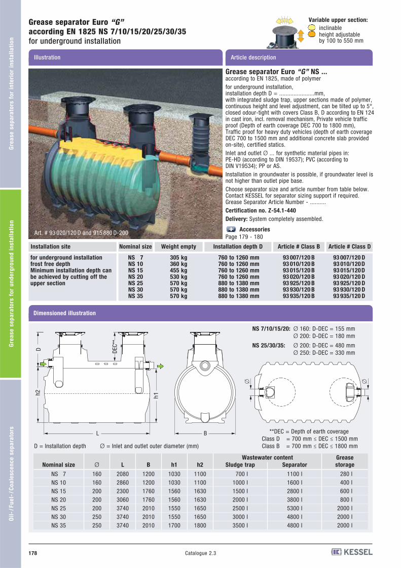
Nominal size Installation depth D
Illustration
Art. # 93 020/120 D and 915 880 D-200
NS 7NS 10NS 15NS 20NS 25NS 30NS 35
305 kg360 kg455 kg530 kg570 kg570 kg570 kg
760 to 1260 mm760 to 1260 mm760 to 1260 mm760 to 1260 mm880 to 1380 mm880 to 1380 mm880 to 1380 mm
for underground installation frost free depthMinimum installation depth canbe achieved by cutting off theupper section
BL
h1h2
� �
Dimensioned illustration
Installation site Article # Class B Article # Class D
93 007/120 B93 010/120 B93 015/120 B93 020/120 B93 925/120 B93 930/120 B93 935/120 B
93 007/120 D93 010/120D93 015/120D93 020/120 D93 925/120 D93 930/120 D93 935/120 D
Nominal size
NS 7NS 10NS 15NS 20NS 25NS 30NS 35
Ø
160160200200200250250
L
2080286023003060374037403740
B
1200120017601760201020102010
h1
1030103015601560155015501700
h2
1100110016301630165016501800
Sludge trap
700 l1000 l1500 l2000 l2500 l3000 l3500 l
Wastewater content
Separator
1100 l1600 l2800 l3800 l5300 l4800 l4800 l
Grease
storage
280 l400 l600 l800 l
2000 l2000 l2000 l
D = Installation depth Ø = Inlet and outlet outer diameter (mm)
**DEC = Depth of earth coverageClass D = 700 mm ≤ DEC ≤ 1500 mmClass B = 700 mm ≤ DEC ≤ 1800 mm
Ø 160: D-DEC = 155 mmØ 200: D-DEC = 180 mm
Ø 200: D-DEC = 480 mmØ 250: D-DEC = 330 mm
NS 7/10/15/20:
NS 25/30/35:
Grease separator Euro “G” NS ...according to EN 1825, made of polymerfor underground installation, installation depth D = ......................mm,with integrated sludge trap, upper sections made of polymer,continuous height and level adjustment, can be tilted up to 5°,closed odour-tight with covers Class B, D according to EN 124in cast iron, incl. removal mechanism, Private vehicle trafficproof (Depth of earth coverage DEC 700 to 1800 mm),Traffic proof for heavy duty vehicles (depth of earth coverageDEC 700 to 1500 mm and additional concrete slab providedon-site), certified statics.Inlet and outlet Ø ... for synthetic material pipes in: PE-HD (according to DIN 19537); PVC (according to DIN V19534); PP or AS.Installation in groundwater is possible, if groundwater level isnot higher than outlet pipe base.Choose separator size and article number from table below.Contact KESSEL for separator sizing support if required.Grease Separator Article Number - ..........Certification no. Z-54.1-440
Delivery: System completely assembled.
Accessories
Page 179 - 180
Grease separator Euro “G”according EN 1825 NS 7/10/15/20/25/30/35for underground installation
Variable upper section:
inclinableheight adjustable by 100 to 550 mm
Article description
D DEC*
*
Weight empty
Oil
-/F
ue
l-/C
oa
les
ce
nc
e s
ep
ara
tors
Gre
as
e s
ep
ara
tors
fo
r u
nd
erg
rou
nd
in
sta
lla
tio
nG
rea
se
se
pa
rato
rs f
or
inte
rio
r in
sta
lla
tio
n
Catalogue 2.3178

Article descriptionIllustration and dimensioned drawing
fits separator
NS 1, NS 2 and NS 4NS 7 and NS 10
NS 15, NS 20 andcustom-made
Installationdepth D (mm)
* 400-1300
* 400-1300
Inlet/outletØ
110/160200
Sampling chamber Ø 400 made of polymerfor separation systems, for underground installation
For connection to outlet pipe of separator. For installation depth D = ...... .Inlet and outlet Ø 110/160 available options Ø 200 for synthetic materialpipes in: PE-HD (according to DIN 19537); PVC (according to DIN V19534);PP or AS. Sampling chamber middle diameter 400 mm, telescopic uppersection with clamping ring, cover Class A/B/D, screwed down odour-tight,drop height 120 mm. Drop height 160 mm on request.
Extension by 600 mm with extension section Art. # 915 402
575750
120
50-4
00
70
100
� 1
60�
110
900
� 1
10�
160
Installationdepth D (mm)
1180-16301180-16301180-1630
Outlet
Ø 110Ø 160Ø 200
Article # Class DClass B
915 10 10 B
915 10 15 B
915 10 20 B
915 10 10 D
915 10 15 D
915 10 20 D
Sampling chamber Ø 1000 mmin polyethylene synthetic material,for separation systems, for underground installation
Inlet and outlet Ø ... for synthetic material pipes in: PE-HD (according to DIN 19537); PVC (according to DIN V19534); PP or AS.Installation depth D ..... mm, in monolithic structure, water-tight, resistantto aggressive wastewater, with integrated access steps, with telescopicallyheight-adjustable upper section made of polymer, sealed odour-tight withcover Class B/D according to EN 124 in cast iron, incl. removal mechanism.Drop height 160 mm.
160
� �
1200
100-
550
Inlet/
Article # Class D
915 880 D
915 880 D-200
Class B
915 880 B
915 880 B-200
Class A
915 880 A
915 880 A-200
* Minimum installation depth can be achieved by cutting off
Other installation depths available on request
Extension section
For deep installationExtension height max. 600 mm (can be reduced).
Check maintenance accessibility when installing in recesses !
Model
Extension height = 600 mm
Article #
915 402
Extension section made of polymerfor separation systems
Fits all KESSEL Separation systems for underground installation,extension height 510 mm / 1010 mm; incl. gasket
smaller/larger extension sections available on request
Model
Extension height = 510 mm
Extension height = 1010 mm
Article #
917 406
917 407
600
�660
�630�806
�686
�740
116
15
628
20°
AccessoriesSeparator according to EN 1825 for underground installation
D
D
Oil
-/F
ue
l-/C
oa
les
ce
nc
e s
ep
ara
tors
Gre
as
e s
ep
ara
tors
fo
r u
nd
erg
rou
nd
in
sta
lla
tio
nG
rea
se
se
pa
rato
rs f
or
inte
rio
r in
sta
lla
tio
n
Catalogue 2.3 179

180 Catalogue 2.3
Gre
as
e s
ep
ara
tors
fo
r in
teri
or
ins
tall
ati
on
G
rea
se
se
pa
rato
rs f
or
un
de
rgro
un
d i
ns
tall
ati
on
Oil
-/F
ue
l-/C
oa
les
ce
nc
e s
ep
ara
tors
Article descriptionIllustration and dimensioned drawing
AccessoriesSeparator according to EN 1825 for underground installation
Article #
917 821
SonicControl level sensing systemwith ultra sonic sensor for grease separators
Accurate monitoring and data transfer of grease levels. 230 V - 50 Hz power connection. With battery back up, connection forremote speaker.Insallation set with easy assembly and maintenance. For use on aboveground or below ground separators. For retrofit use on existing separators.Control unit with optical and audible alarm with potential free contact.Electronic log book with 12 month capacity. Data transfer by telemetry.
Voltage: 230 V ~ 50 Hz; Protection: IP 54;Plug: Schuko 1,5 m;Cable length: 10 m (extendable on-site to 30 meters).
Cable access conduit
Required for watertight connection of SonicControl cable into separator chamber.
Article #
917 822
AccessoriesAudible alarm Art. # 20 162,25 m cable extension available upon request.PE-HD Cable access conduit Art. # 917 822
Underground lifting stations for use after grease separatorscan be seen in the lifting station sectionpage 53 - 63.
Article #
917 414
Article #
917 413
Stainless steel access panel
For recessed wall installationwith Storz-B disposal pipe hook up connection and remote control connection for use with fully automated grease separators.Remote control not included.Dimensions: 640 x 440 x 160 mm (Width x Height x Depth)Model: “Recessed”, 2 doors, lockable
Stainless steel access panel
For wall installationwith Storz-B disposal pipe hook-up connection and remote control connection for use with fully automated grease separators.Remote control not included.Dimensions: 600 x 400 x 160 mm (Width x Height x Depth)Model: “Wall installation”, 2 doors, lockable
640600
440
400
160
Remote Control mounting area
Storz-B-Coupling connection
600
400
160
Remote Control mounting area
Storz-B-Coupling connection

181Catalogue 2.3
Oil-/Fuel separators Coalescence separators
PPoollyy
eetthhyy
lleennee WWaarrrraannttyy
202 YeY ars
Gre
as
e s
ep
ara
tors
fo
r in
teri
or
ins
tall
ati
on
G
rea
se
se
pa
rato
rs f
or
un
de
rgro
un
d i
ns
tall
ati
on
Oil
-/F
ue
l-/C
oa
les
ce
nc
e s
ep
ara
tors

-Professional advantagesOil-/Fuel separators
Coalescence separators
SonicControl
182 Catalogue 2.3
Gre
as
e s
ep
ara
tors
fo
r in
teri
or
ins
tall
ati
on
G
rea
se
se
pa
rato
rs f
or
un
de
rgro
un
d i
ns
tall
ati
on
Oil
-/F
ue
l-/C
oa
les
ce
nc
e s
ep
ara
tors
In addition to the standard KESSEL guarantee,
KESSEL offers an additional guarantee of
20 years on the polyethylene oil / fuel and
coalescence separator tanks - this covers the
structural integrity, watertightness and usability
of the polyethylene components.
Poly
et
hylene Warranty
Poly
et
hylene Warranty
20 Years
Our coalescence separators
are certified for bio-diesel use
Guaranteed leak tight system
Watertight gasketed connection between upper section andseparator assure that environmentally damaging fuel doesnot enter earth / groundwater supply
Vertically adjustable
upper sections standard
with separator
Included upper sections allowon-site vertical adjustability ofup to 500 mm and a lateral til-ting of up to 5°. The odour tightmanhole covers are available inload classes A/B and D.
Product - see page 187
Products - see pages 183 - 186
SonicControlautomated fuel level measuring system Monitoring and notification of oil and sludge layer thickness andback-up / overflow warning
According to Euronorm EN 858-1, fuel separator must be equippedwith automated warning systems. The KESSEL SonicControl systemfor fuel / coalescence separators offers reliable and accurate mo-nitoring of the fuel level, sludge height and back-up / flood levels.
Oil layer thickness (d1)
Sludge layer thickness (d2)
Measuredvalue(m2)
Measuredvalue(m1)
Control value (r1)
Control value (r2)
Three warning features in one system
- cm accurate monitoring of the fuel layer- cm accurate monitoring of the sludge layer- back-up / overflow warning
Operation via control unit
USB connection for downloading logbook
Quick and easy installation
For use with all KESSEL oil and coalescence separators
Retro-fitting of existing separators
Read out software SonicControl Viewer
Oil layer thickness (d1) = [Control value (r1) - Measured value (m1)] x 1,2
Sludge layer thickness (d2) = Control value (r2) - Measured value (m2)
The German DIBt certification agency (German Institue for Building Technology) has granted a full DIBt certi-fication for the KESSEL oil / fuel and coalescence separators. With this KESSEL is the first German manufacturer to be granted this certification for polyethylene separators.
Polyethylene oil / fuel and coalescence separators offer significantadvantages for engineers, architects, installation companies aswell as building owners and operators. The fully watertight bodiesare also fracture resistant meaning ultra-long life expectancy.
183Catalogue 2.3
Gre
as
e s
ep
ara
tors
fo
r in
teri
or
ins
tall
ati
on
G
rea
se
se
pa
rato
rs f
or
un
de
rgro
un
d i
ns
tall
ati
on
Oil
-/F
ue
l-/C
oa
les
ce
nc
e s
ep
ara
tors
* Ø =
Illustration and dimensioned drawing
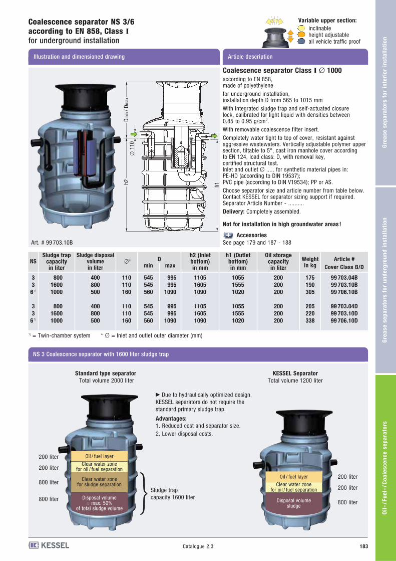
Coalescence separator NS 3/6 according to EN 858, Class Ifor underground installation
Article description
Variable upper section:
inclinableheight adjustable all vehicle traffic proof
Coalescence separator Class I Ø 1000
according to EN 858, made of polyethylenefor underground installation, installation depth D from 565 to 1015 mmWith integrated sludge trap and self-actuated closure lock, calibrated for light liquid with densities between 0.85 to 0.95 g/cm3.With removable coalescence filter insert.Completely water tight to top of cover, resistant againstaggressive wastewaters. Vertically adjustable polymer uppersection, tiltable to 5°, cast iron manhole cover according to EN 124, load class: D, with removal key, certified structural test.Inlet and outlet Ø ..... for synthetic material pipes in: PE-HD (according to DIN 19537); PVC pipe (according to DIN V19534); PP or AS.Choose separator size and article number from table below.Contact KESSEL for separator sizing support if required.Separator Article Number - .......... Delivery: Completely assembled.
Not for installation in high groundwater areas !
Accessories
See page 179 and 187 - 188Art. # 99 703.10B
�
Dmin
/ Dm
axh2 h1
� 1
10
NS 3 Coalescence separator with 1600 liter sludge trap
Due to hydraulically optimized design,KESSEL separators do not require the standard primary sludge trap.
Advantages:
1. Reduced cost and separator size.2. Lower disposal costs.
Standard type separator
Total volume 2000 literKESSEL Separator
Total volume 1200 liter
200 liter
200 liter
800 liter
800 liter
Oil / fuel layer
Clear water zone for oil / fuel separation
Clear water zone for sludge separation
Disposal volume = max. 50%
of total sludge volume
Oil / fuel layer
Clear water zone for oil / fuel separation
Disposal volume sludge
200 liter
200 liter
800 liter
Sludge trap capacity 1600 liter�
3
3
6 1)
3
3
6 1)
NS
400
800
500
400
800
500
Sludge disposalvolume in liter
800
1600
1000
800
1600
1000
Sludge trapcapacity in liter
110
110
160
110
110
160
Ø*
545
545
560
545
545
560
1105
1605
1090
1105
1605
1090
1055
1555
1020
1055
1555
1020
h2 (Inlet bottom) in mm
h1 (Outlet bottom) in mm
200
200
200
200
200
200
Oil storage capacity in liter
175
190
305
205
220
338
995
995
1090
995
995
1090
min maxD Weight
in kg
99 703.04B
99 703.10B
99 706.10B
99 703.04D
99 703.10D
99 706.10D
Article #
Cover Class B/D
1) = Twin-chamber system * Ø = Inlet and outlet outer diameter (mm)

Dimensioned illustration
L
h 2 h1
B
� �
Class D = 700 mm � DEC � 1500 mmClass B = 700 mm � DEC � 1800 mm
Ø 160: D-DEC = 155 mmØ 200: D-DEC = 180 mm
**DEC = Depth of earth coverage
1) Comparable sludge trap total volume in accordance with the dimensioning according to EN 858. 2) eccentric reduction inlet/outlet to Ø 160 possible on-site, as a consequence the sampling chamber 915880 A/B/D can be used see page 179.
Coalescence separator
according to EN 858, made of polymerfor underground installation, installation depth D =...................... mmWith integrated sludge trap and self-actuated closure lock, calibrated for light liquid with densities between 0.85 to 0.95 g/cm3.With removable coalescence filter.Upper sections made of polymer, continuous height and leveladjustment, tiltable to 5°, with covers Class B, D according to EN 124 in cast iron, including removal mecha-nism, private vehicle traffic proof (depth of earth coverage DEC 700 to 1800 mm), traffic proof for heavy dutyvehicles (depth of earth coverage DEC 700 to 1500 mm andadditional concrete slab provided on-site), certified statics, Inlet and outlet Ø ... for synthetic material pipes in: PE-HD (according to DIN 19537); PVC pipe (according to DIN V19534); PP or AS.Choose separator size and article number from table below.Contact KESSEL for separator sizing support if required.Separator Article Number - .......... Certification no. Z-54.3-454
Accessories
Sampling chamber for underground installation see page 179. Extension section for deep installation see page 179.Alarm units for when the maximum oil level is reached and there is a back-up of water (required according to EN 858) see page 187.Oil and sludge suction system see page 187.
Illustration
Coalescence separator NS 3 - NS 15 according to EN 858, Class Ifor underground installation with DIBt-Certification
Art. # 99 710.80 D EX
Also suitable for filling
stations with high-perfor-
mance filling pumps
Variable upper section:
inclinable
Article description
D DEC*
*
height adjustable all vehicle traffic proof
Article # Cover
Class D
Article # Cover
Class B
99 503.10D EX
99 706.30D EX
99 706.80D EX
99 710.15D EX
99 710.30D EX
99 710.80D EX
99 715.80D EX
99 503.10B EX
99 706.30B EX
99 706.80B EX
99 710.15B EX
99 710.30B EX
99 710.80B EX
99 715.80B EX
Weightin kg
395535610440535610610
Oil storagecapacityin Liter
187265380262265380380
h1 inmm
1040156015601040156015601560
h2 inmm
1100163016301100163016301630
B inmm
1200176017601200176017601760
L inmm
2080230030602860230030603060
Ø*
160200200160200200200
Sludge trapcapacityin Liter
1000250050001500250050005000
1)
1)
NS
3
6
6
10
10
10
15
D in mmmin max
840850870840850870870
1240123012501240123012501250
2)
2)
2)
2)
Oil
-/F
ue
l-/C
oa
les
ce
nc
e s
ep
ara
tors
Gre
as
e s
ep
ara
tors
fo
r u
nd
erg
rou
nd
in
sta
lla
tio
nG
rea
se
se
pa
rato
rs f
or
inte
rio
r in
sta
lla
tio
n
Catalogue 2.3184
* Ø = Inlet and outlet outer diameter (mm)

Oil
-/F
ue
l-/C
oa
les
ce
nc
e s
ep
ara
tors
Gre
as
e s
ep
ara
tors
fo
r u
nd
erg
rou
nd
in
sta
lla
tio
nG
rea
se
se
pa
rato
rs f
or
inte
rio
r in
sta
lla
tio
n
Catalogue 2.3 185
Oil/fuel separator NS 3 - NS 15according to EN 858, Class IIfor underground installation
Illustration
Variable upper section:
inclinable
Art. # 99 610.80Art. # 99 610.80 D EX
Dimensioned illustration
L
h 2 h1
B
� �
Class D = 700 mm � DEC � 1500 mmClass B = 700 mm � DEC � 1800 mm
**DEC = Depth of earth coverage
1) Comparable sludge trap total volume in accordance with the dimensioning according to EN 858-2. 2) eccentric reduction inlet/outlet to Ø 160 possible on-site, as a consequence the sampling chamber 915880 A/B/D can be used see page 179.
Article # Cover
Class D
Article # Cover
Class B
99 403.10D EX
99 606.30D EX
99 606.80D EX
99 610.15D EX
99 610.30D EX
99 610.80D EX
99 615.80D EX
99 403.10B EX
99 606.30B EX
99 606.80B EX
99 610.15B EX
99 610.30B EX
99 610.80B EX
99 615.80B EX
Weightin kg
379519594424519594594
Oil storagecapacityin Liter
187265380262265380380
h1 inmm
1040156015601040156015601560
h2 inmm
1100163016301100163016301630
B inmm
1200176017601200176017601760
L inmm
2080230030602860230030603060
Ø*
160200200160200200200
Sludge trapcapacityin Liter
1000250050001500250050005000
1)
1)
NS
3
6
6
10
10
10
15
D in mmmin max
840850870840850870870
1240123012501240123012501250
Ø 160: D-DEC = 155 mmØ 200: D-DEC = 180 mm
2)
2)
2)
Also suitable for filling
stations with high-perfor-
mance filling pumps
Article description
height adjustable by 100 to 550 mmall vehicle traffic proof
D DEC*
*
Oil/fuel separator
according to EN 858, made of polymerfor underground installation, installation depth D =...................... mmWith integrated sludge trap and self-actuated closure lock, calibrated for light liquid with densities between 0.85 to 0.95 g/cm3.Upper sections made of polymer, continuous height and leveladjustment, tiltable up to 5°, with covers Class B, D accordingto EN 124 in cast iron, incl. removal mechanism, private vehi-cle traffic proof (depth of earth coverage DEC 700 to 1800 mm),traffic proof for heavy duty vehicles (depth of earth coverageDEC 700 to 1500 mm and additional concrete slab providedon-site), certified statics, Inlet and outlet Ø ... for synthetic material pipes in: PE-HD (according to DIN 19537);PVC pipe (according to DIN V19534); PP or AS.Choose separator size and article number from table below.Contact KESSEL for separator sizing support if required.Separator Article Number - ..........
Certification no. Z-54.2-453
Accessories
Sampling chamber for underground installation see page 179. Extension section for deep installation see page 179.Alarm units when the maximum oil level is reached and there is a back-up of water (required according to EN 858) see page 187.Oil and sludge suction system see page 187.Coalescence filter insert for retrofitting to the coalescenceseparator see page 188.
* Ø = Inlet and outlet outer diameter (mm)

Art. # 99 601.002B
�
L
h2 h1
Oil/fuel separator NS 1.5according to KESSEL Standardfor underground installation
Illustration and dimensioned drawing
Oil/fuel separator Class II Ø 1000
according to KESSEL Standardfor underground installation, installation depth D = ...................... mm.With integrated sludge trap and self-actuated closure lock, calibrated for light liquid with densities between 0.85 to 0.95 g/cm3.Optional with backwater flap valve according to DIN 13564Upper sections made of polymer, continuous height and leveladjustment, cover Class A/B.Inlet and outlet Ø 110 for synthetic material pipes in: PE-HD (according to DIN 19537); PVC pipe (according to DIN V19534); PP or AS.
Accessories
Sampling chamber for underground installation see page 179.Alarm unit when the maximum oil level is reached and thereis a back-up of water (required according to EN 858) see page 187.
Oil/fuel separator Class II Ø 800
according to KESSEL Standardfor underground installation, installation depth D = ...................... mm.With integrated sludge trap and self-actuated closure lock, calibrated for light liquid with densities between 0.85 to 0.95 g/cm3.Optional with backwater flap valve according to DIN 13564Upper sections made of polymer, continuous height and leveladjustment, cover Class A/B.Inlet and outlet Ø 110 for synthetic material pipes in: PE-HD (according to DIN 19537); PVC pipe (according to DIN V19534); PP or AS.
Accessories
Sampling chamber for underground installation see page 179.Alarm unit when the maximum oil level is reached and thereis a back-up of water (required according to EN 858) see page 187.Art. # 99 601.016B/D
�
L
h2 h1
Sludge trap
capacity
17 l
130 l
360 l
Ø
110
110
110
L
582
1091
1425
B
520
1012
1300
min
231
518
570
h2 (Inlet
bottom)
389 mm
508 mm
630 mm
h1 (Outlet
bottom)
342 mm
461 mm
583 mm
Oil storage
capacity
17.6 l
70.5 l
110 l
Excess
level
50
50
70
Weight
in kg
12
74
110
Article #
Class B
99 601.002B
99 601.016B
-
max
324
942
995
NS
1.5
1.5
1.5
D
Art. # 99 601.041B/D�
L
h2 h1
rotatableVariable upper section:
inclinableheight adjustablePrivate vehicle proof
Article description
D
D
D
Oil/fuel separator Class II Ø 400
according to KESSEL Standardfor underground installation, installation depth D = ...................... mm.With integrated small sludge trap and self-actuated closurelock, calibrated for light liquid with densities between 0.85 to 0.95 g/cm3.Optional with backwater flap valve according to DIN 13564Upper sections made of polymer, continuous height and leveladjustment, cover Class A/B.Inlet and outlet Ø 110 for synthetic material pipes in: PE-HD (according to DIN 19537); PVC pipe (according to DIN V19534); PP or AS.
Accessories
Sampling chamber for underground installation see page 179.
Oil
-/F
ue
l-/C
oa
les
ce
nc
e s
ep
ara
tors
Gre
as
e s
ep
ara
tors
fo
r u
nd
erg
rou
nd
in
sta
lla
tio
nG
rea
se
se
pa
rato
rs f
or
inte
rio
r in
sta
lla
tio
n
Catalogue 2.3186
Class D
-
99 601.016D
99 601.041D
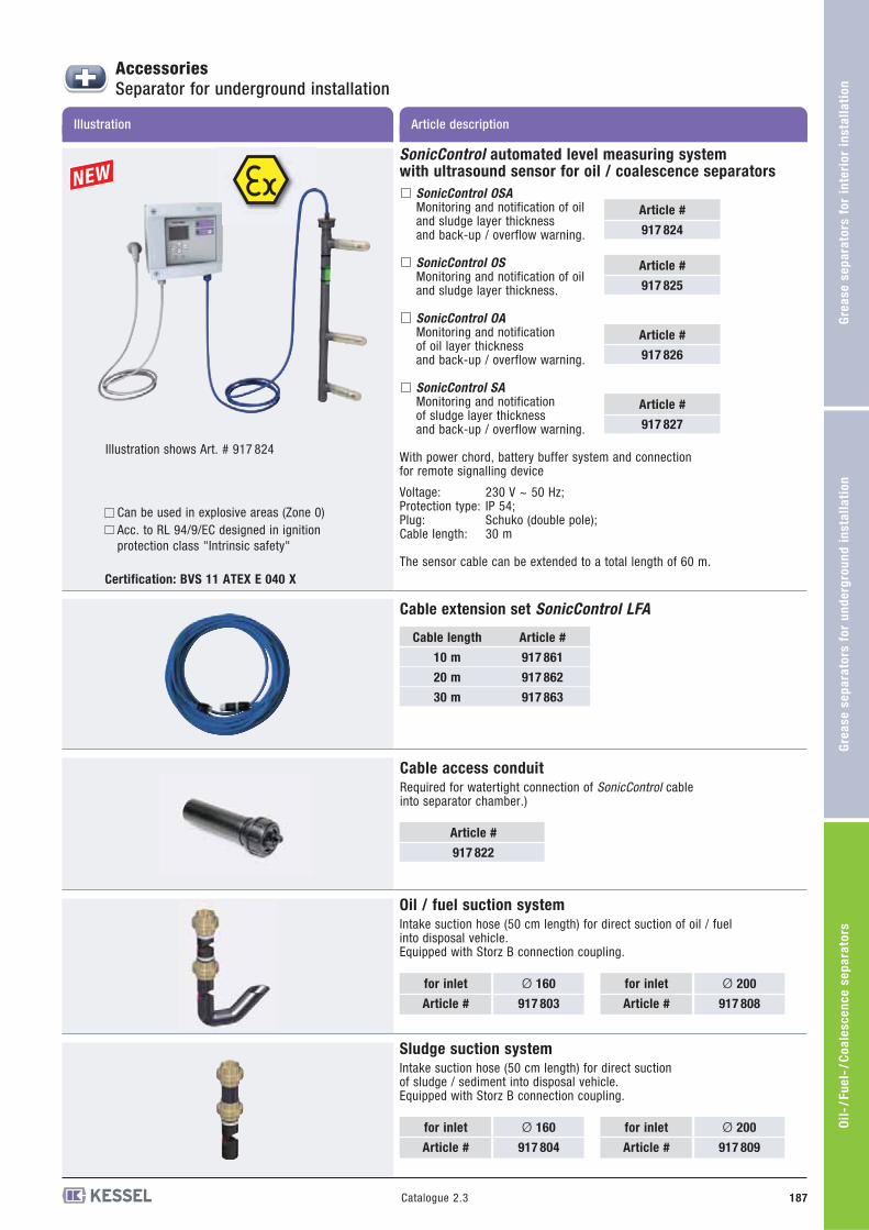
Oil
-/F
ue
l-/C
oa
les
ce
nc
e s
ep
ara
tors
Gre
as
e s
ep
ara
tors
fo
r u
nd
erg
rou
nd
in
sta
lla
tio
nG
rea
se
se
pa
rato
rs f
or
inte
rio
r in
sta
lla
tio
n
Catalogue 2.3 187
Oil / fuel suction system
Intake suction hose (50 cm length) for direct suction of oil / fuel into disposal vehicle.Equipped with Storz B connection coupling.
Sludge suction system
Intake suction hose (50 cm length) for direct suction of sludge / sediment into disposal vehicle.Equipped with Storz B connection coupling.
for inlet
Article #
Ø 200
917 808
for inlet
Article #
Ø 160
917 803
for inlet
Article #
Ø 200
917 809
for inlet
Article #
Ø 160
917 804
Article descriptionIllustration
AccessoriesSeparator for underground installation
SonicControl automated level measuring system with ultrasound sensor for oil / coalescence separators
SonicControl OSAMonitoring and notification of oiland sludge layer thicknessand back-up / overflow warning.
SonicControl OSMonitoring and notification of oiland sludge layer thickness.
SonicControl OAMonitoring and notificationof oil layer thicknessand back-up / overflow warning.
SonicControl SAMonitoring and notificationof sludge layer thicknessand back-up / overflow warning.
With power chord, battery buffer system and connection for remote signalling device
Voltage: 230 V ~ 50 Hz; Protection type: IP 54;Plug: Schuko (double pole);Cable length: 30 m
The sensor cable can be extended to a total length of 60 m.
Article #
917 824
Article #
917 825
Article #
917 826
Article #
917 827
Illustration shows Art. # 917 824
Can be used in explosive areas (Zone 0)Acc. to RL 94/9/EC designed in ignitionprotection class "Intrinsic safety"
Cable extension set SonicControl LFA
Cable length
10 m
20 m
30 m
Article #
917 861
917 862
917 863
Cable access conduit
Required for watertight connection of SonicControl cable into separator chamber.)
Article #
917 822
Certification: BVS 11 ATEX E 040 X

188 Catalogue 2.3
Gre
as
e s
ep
ara
tors
fo
r in
teri
or
ins
tall
ati
on
G
rea
se
se
pa
rato
rs f
or
un
de
rgro
un
d i
ns
tall
ati
on
Oil
-/F
ue
l-/C
oa
les
ce
nc
e s
ep
ara
tors
Article descriptionIllustration
AccessoriesSeparator for underground installation
Coalescence filter insert
for retrofitting the KESSEL Oil/fuel separator NS 3-NS 15 to coalescence separator
Article #
917 805
Coalescence filter
for KESSEL coalescence separator Class I Ø 1000
Article #
917 816
Local weather conditions or cooling of the tank during installation(due to filling with cold water for example) can cause slightdimensional changes. Because of this, please check the actualtank dimensions during installation, especially tank height.