kernel extensions and device support programming...
TRANSCRIPT

Bull Kernel Extensions and Device Support
Programming Concepts
AIX
86 A2 36JX 02
ORDER REFERENCE


Bull Kernel Extensions and Device Support
Programming Concepts
AIX
Software
November 1999
BULL ELECTRONICS ANGERS
CEDOC
34 Rue du Nid de Pie – BP 428
49004 ANGERS CEDEX 01
FRANCE
86 A2 36JX 02
ORDER REFERENCE

The following copyright notice protects this book under the Copyright laws of the United States of America
and other countries which prohibit such actions as, but not limited to, copying, distributing, modifying, and
making derivative works.
Copyright Bull S.A. 1992, 1999
Printed in France
Suggestions and criticisms concerning the form, content, and presentation of
this book are invited. A form is provided at the end of this book for this purpose.
To order additional copies of this book or other Bull Technical Publications, you
are invited to use the Ordering Form also provided at the end of this book.
Trademarks and Acknowledgements
We acknowledge the right of proprietors of trademarks mentioned in this book.
AIX� is a registered trademark of International Business Machines Corporation, and is being used under
licence.
UNIX is a registered trademark in the United States of America and other countries licensed exclusively through
the Open Group.
Year 2000
The product documented in this manual is Year 2000 Ready.
The information in this document is subject to change without notice. Groupe Bull will not be liable for errors
contained herein, or for incidental or consequential damages in connection with the use of this material.

Contents
Trademarks and Acknowledgements . . iii
About This Book . . . . . . . . . . xvWho Should Use This Book . . . . . . . . . xvHow to Use This Book . . . . . . . . . . xv
Overview of Contents . . . . . . . . . . xvHighlighting . . . . . . . . . . . . . xvi
ISO 9000 . . . . . . . . . . . . . . . xviAIX 32-Bit Support for the X/Open UNIX95Specification . . . . . . . . . . . . . . xviAIX 32-Bit and 64-Bit Support for the UNIX98Specification . . . . . . . . . . . . . xviiRelated Publications . . . . . . . . . . . xviiOrdering Publications . . . . . . . . . . xvii
Chapter 1. Kernel Environment . . . . . 1Understanding Kernel Extension Binding . . . . . 2
Base Kernel Services - the /unix Name Space . . 2Using System Calls with Kernel Extensions . . . 3Using Private Routines . . . . . . . . . . 4Using Libraries . . . . . . . . . . . . 5
Understanding Execution Environments . . . . . 7Process Environment . . . . . . . . . . 8Interrupt Environment . . . . . . . . . . 8
Understanding Kernel Threads . . . . . . . . 9Kernel Threads, Kernel Only Threads, and UserThreads . . . . . . . . . . . . . . . 9Kernel Data Structures. . . . . . . . . . 10Thread Creation, Execution, and Termination . . 10Thread Scheduling . . . . . . . . . . . 10Thread Signal Handling . . . . . . . . . 10
Using Kernel Processes . . . . . . . . . . 11Introduction to Kernel Processes . . . . . . 11Accessing Data from a Kernel Process . . . . 12Cross-Memory Services . . . . . . . . . 13Kernel Process Creation, Execution, andTermination . . . . . . . . . . . . . 13Kernel Process Preemption . . . . . . . . 14Kernel Process Signal and Exception Handling . 14Kernel Process Use of System Calls . . . . . 15
Accessing User-Mode Data While in Kernel Mode 15Data Transfer Services . . . . . . . . . . 15Using Cross-Memory Kernel Services . . . . . 16
Understanding Locking . . . . . . . . . . 16Lockl Locks . . . . . . . . . . . . . 16Simple Locks . . . . . . . . . . . . . 17Complex Locks . . . . . . . . . . . . 17Types of Critical Sections . . . . . . . . . 17Priority Promotion . . . . . . . . . . . 17Locking Strategy in Kernel Mode . . . . . . 17
Understanding Exception Handling . . . . . . 18Exception Processing . . . . . . . . . . 18Kernel-Mode Exception Handling . . . . . . 18Implementing Kernel Exception Handlers . . . 20User-Mode Exception Handling . . . . . . 23
64-bit Kernel Extension Development . . . . . . 23
Chapter 2. System Calls . . . . . . . 25Differences Between a System Call and a UserFunction . . . . . . . . . . . . . . . 25Understanding System Call Execution . . . . . 25
User Protection Domain . . . . . . . . . 26Kernel Protection Domain . . . . . . . . 26Actions of the System Call Handler . . . . . 26Accessing Kernel Data While in a System Call . . 27Preempting a System Call . . . . . . . . 28Handling Signals While in a System Call . . . 28Handling Exceptions While in a System Call . . 29Understanding Nesting and Kernel-Mode Use ofSystem Calls . . . . . . . . . . . . . 30Page Faulting within System Calls . . . . . . 30Returning Error Information from System Calls 31
System Calls Available to Kernel Extensions . . . 31System Calls Available to All Kernel Extensions 31System Calls Available to Kernel Processes Only 32
Chapter 3. Virtual File Systems . . . . 33Logical File System Overview . . . . . . . . 33
Component Structure of the Logical File System 34Virtual File System Overview . . . . . . . . 35
Understanding Virtual Nodes (V-nodes) . . . . 35Understanding Generic I-nodes (G-nodes) . . . 35Understanding the Virtual File System Interface 36
Understanding Data Structures and Header Files forVirtual File Systems . . . . . . . . . . . 37Configuring a Virtual File System . . . . . . . 38
Chapter 4. Kernel Services . . . . . . 39Categories of Kernel Services . . . . . . . . 39I/O Kernel Services . . . . . . . . . . . 39
Block I/O Kernel Services . . . . . . . . 39Buffer Cache Kernel Services . . . . . . . 40Character I/O Kernel Services . . . . . . . 40Interrupt Management Services . . . . . . . 40Memory Buffer (mbuf) Kernel Services . . . . 41DMA Management Kernel Services . . . . . 42
Block I/O Buffer Cache Kernel Services: Overview 42Managing the Buffer Cache . . . . . . . . 43Using the Buffer Cache write Services . . . . 43
Understanding Interrupts. . . . . . . . . . 44Interrupt Priorities . . . . . . . . . . . 44
Understanding DMA Transfers . . . . . . . . 44Hiding DMA Data . . . . . . . . . . . 45Accessing Data While the DMA Operation Is inProgress . . . . . . . . . . . . . . 45
Kernel Extension and Device Driver ManagementKernel Services . . . . . . . . . . . . . 46
Kernel Extension Loading and Binding Services 46Other Functions for the Kernel Extension andDevice Driver Management Services . . . . . 46
© Copyright IBM Corp. 1997, 1999 v

List of Kernel Extension and Device DriverManagement Kernel Services . . . . . . . 47
Locking Kernel Services . . . . . . . . . . 48Lock Allocation and Other Services . . . . . 48Simple Locks . . . . . . . . . . . . . 48Complex Locks . . . . . . . . . . . . 49Lockl Locks . . . . . . . . . . . . . 50Atomic Lock Operations . . . . . . . . . 50Atomic Operations . . . . . . . . . . . 51
File Descriptor Management Services . . . . . . 51Logical File System Kernel Services . . . . . . 51
Other Considerations . . . . . . . . . . 52List of Logical File System Kernel Services . . . 52
Memory Kernel Services . . . . . . . . . . 53Memory Management Kernel Services . . . . 53Memory Pinning Kernel Services . . . . . . 53User Memory Access Kernel Services . . . . . 54Virtual Memory Management Kernel Services . . 54Cross-Memory Kernel Services . . . . . . . 55
Understanding Virtual Memory Manager Interfaces 56Virtual Memory Objects . . . . . . . . . 56Addressing Data. . . . . . . . . . . . 57Moving Data to or from a Virtual Memory Object 57Data Flushing . . . . . . . . . . . . 57Discarding Data . . . . . . . . . . . . 57Protecting Data . . . . . . . . . . . . 58Executable Data . . . . . . . . . . . . 58Installing Pager Backends. . . . . . . . . 58Referenced Routines . . . . . . . . . . 58Services that Support 64-bit Processes . . . . 59
Message Queue Kernel Services . . . . . . . 60Network Kernel Services . . . . . . . . . . 61
Address Family Domain and Network InterfaceDevice Driver Kernel Services . . . . . . . 61Routing and Interface Address Kernel Services 62Loopback Kernel Services. . . . . . . . . 62Protocol Kernel Services . . . . . . . . . 62Communications Device Handler Interface KernelServices . . . . . . . . . . . . . . 63
Process and Exception Management Kernel Services 63Creating Kernel Processes . . . . . . . . 63Creating Kernel Threads . . . . . . . . . 63Kernel Structures Encapsulation . . . . . . 64Registering Exception Handlers. . . . . . . 64Signal Management. . . . . . . . . . . 64Events Management . . . . . . . . . . 64List of Process, Thread, and ExceptionManagement Kernel Services . . . . . . . 65
RAS Kernel Services . . . . . . . . . . . 66List of RAS Kernel Services . . . . . . . . 66
Security Kernel Services . . . . . . . . . . 67Timer and Time-of-Day Kernel Services . . . . . 67
Time-Of-Day Kernel Services . . . . . . . 67Fine Granularity Timer Kernel Services . . . . 67Timer Kernel Services for Compatibility . . . . 68Watchdog Timer Kernel Services . . . . . . 68
Using Fine Granularity Timer Services andStructures . . . . . . . . . . . . . . . 68
Timer Services Data Structures . . . . . . . 68Coding the Timer Function . . . . . . . . 69
Using Multiprocessor-Safe Timer Services . . . . 69
Virtual File System (VFS) Kernel Services . . . . 69
Chapter 5. Asynchronous I/OSubsystem . . . . . . . . . . . . . 71Asynchronous I/O Overview . . . . . . . . 71
How do I know if I need to use AIO? . . . . 72How many AIO Servers am I currently using?. . 72How many AIO servers do I need? . . . . . 73
Prerequisites . . . . . . . . . . . . . . 73Functions of Asynchronous I/O . . . . . . . 73
Large File-Enabled Asynchronous I/O (AIXVersion 4.2.1 or later) . . . . . . . . . . 73Nonblocking I/O . . . . . . . . . . . 74Notification of I/O Completion. . . . . . . 74Cancellation of I/O Requests . . . . . . . 75
Asynchronous I/O Subroutines . . . . . . . . 75Order and Priority of Asynchronous I/O Calls . 76
Subroutines Affected by Asynchronous I/O . . . 76Changing Attributes for Asynchronous I/O. . . . 7664-bit Enhancements . . . . . . . . . . . 77
Chapter 6. Device ConfigurationSubsystem . . . . . . . . . . . . . 79Scope of Device Configuration Support . . . . . 79Device Configuration Subsystem Overview . . . . 79General Structure of the Device ConfigurationSubsystem . . . . . . . . . . . . . . . 80
High-Level Perspective . . . . . . . . . 83Device Method Level . . . . . . . . . . 84Low-Level Perspective. . . . . . . . . . 84
Device Configuration Database Overview . . . . 84Basic Device Configuration Procedures Overview. . 85Device Configuration Manager Overview . . . . 85
Devices Graph . . . . . . . . . . . . 86Configuration Rules . . . . . . . . . . 86Invoking the Configuration Manager . . . . . 87
Device Classes, Subclasses, and Types Overview . . 87Writing a Device Method . . . . . . . . . . 88
Invoking Methods . . . . . . . . . . . 88Example Methods . . . . . . . . . . . 88
Understanding Device Methods Interfaces . . . . 89Configuration Manager . . . . . . . . . 89Run-Time Configuration Commands . . . . . 90
Understanding Device States . . . . . . . . 90Adding an Unsupported Device to the System . . 92
Modifying the Predefined Database . . . . . 92Adding Device Methods . . . . . . . . . 92Adding a Device Driver . . . . . . . . . 93Using installp Procedures. . . . . . . . . 93
Understanding Device Dependencies and ChildDevices . . . . . . . . . . . . . . . . 93Accessing Device Attributes . . . . . . . . . 94
Modifying an Attribute Value . . . . . . . 95Device Dependent Structure (DDS) Overview . . . 95
How the Change Method Updates the DDS . . 96Guidelines for DDS Structure . . . . . . . 96Example of DDS. . . . . . . . . . . . 97
List of Device Configuration Commands . . . . 97List of Device Configuration Subroutines . . . . 98
vi Kernel Extensions and Device Support Programming Concepts

Chapter 7. Communications I/OSubsystem . . . . . . . . . . . . . 99User-Mode Interface to a Communications PDH . . 99Kernel-Mode Interface to a Communications PDH 99CDLI Device Drivers . . . . . . . . . . . 100Communications Physical Device Handler ModelOverview. . . . . . . . . . . . . . . 100
Use of mbuf Structures in the CommunicationsPDH . . . . . . . . . . . . . . . 101Common Communications Status and ExceptionCodes . . . . . . . . . . . . . . . 101
Status Blocks for Communications Device HandlersOverview. . . . . . . . . . . . . . . 102
CIO_START_DONE . . . . . . . . . . 102CIO_HALT_DONE . . . . . . . . . . 102CIO_TX_DONE . . . . . . . . . . . 103CIO_NULL_BLK . . . . . . . . . . . 103CIO_LOST_STATUS . . . . . . . . . . 103CIO_ASYNC_STATUS . . . . . . . . . 103
MPQP Device Handler Interface Overview . . . 104Binary Synchronous Communication (BSC) withthe MPQP Adapter . . . . . . . . . . 104Description of the MPQP Card . . . . . . 105
Serial Optical Link Device Handler Overview . . 108Special Files . . . . . . . . . . . . . 108Entry Points . . . . . . . . . . . . . 108
Configuring the Serial Optical Link Device Driver 109Physical and Logical Devices . . . . . . . 109Changeable Attributes of the Serial Optical LinkSubsystem . . . . . . . . . . . . . 110
Forum-Compliant ATM LAN Emulation DeviceDriver . . . . . . . . . . . . . . . . 110
Adding ATM LANE Clients . . . . . . . 113Configuration Parameters for the ATM LANEDevice Driver . . . . . . . . . . . . 113Device Driver Configuration andUnconfiguration . . . . . . . . . . . 118Device Driver Open . . . . . . . . . . 118Device Driver Close . . . . . . . . . . 118Data Transmission . . . . . . . . . . . 118Data Reception . . . . . . . . . . . . 119Asynchronous Status . . . . . . . . . . 119Device Control Operations . . . . . . . . 120Tracing and Error Logging in the ATM LANEDevice Driver . . . . . . . . . . . . 124Adding an ATM MPOA Client . . . . . . 124Configuration Parameters for ATM MPOAClient . . . . . . . . . . . . . . . 126Tracing and Error Logging in the ATM MPOAClient . . . . . . . . . . . . . . . 126
Fiber Distributed Data Interface (FDDI) DeviceDriver . . . . . . . . . . . . . . . . 127
Configuration Parameters for FDDI DeviceDriver . . . . . . . . . . . . . . . 127FDDI Device Driver Configuration andUnconfiguration . . . . . . . . . . . 128Device Driver Open . . . . . . . . . . 128Device Driver Close . . . . . . . . . . 128Data Transmission . . . . . . . . . . . 128Data Reception . . . . . . . . . . . . 129
Reliability, Availability, and Serviceability forFDDI Device Driver . . . . . . . . . . 129
High-Performance (8fc8) Token-Ring Device Driver 131Configuration Parameters for Token-Ring DeviceDriver . . . . . . . . . . . . . . . 132Device Driver Configuration andUnconfiguration . . . . . . . . . . . 132Device Driver Open . . . . . . . . . . 132Device Driver Close . . . . . . . . . . 132Data Transmission . . . . . . . . . . . 133Data Reception . . . . . . . . . . . . 133Asynchronous Status . . . . . . . . . . 133Device Control Operations . . . . . . . . 136Trace Points and Error Log Templates for 8fc8Token-Ring Device Driver . . . . . . . . 138
High-Performance (8fa2) Token-Ring Device Driver 140Configuration Parameters for 8fa2 Token-RingDevice Driver . . . . . . . . . . . . 141Device Driver Configuration andUnconfiguration . . . . . . . . . . . 141Device Driver Open . . . . . . . . . . 141Device Driver Close . . . . . . . . . . 142Data Transmission . . . . . . . . . . . 142Data Reception . . . . . . . . . . . . 142Asynchronous Status . . . . . . . . . . 143Device Control Operations . . . . . . . . 145Trace Points and Error Log Templates for 8fa2Token-Ring Device Driver . . . . . . . . 147
PCI Token-Ring High Performance (14101800)Device Driver . . . . . . . . . . . . . 149
Configuration Parameters . . . . . . . . 150Device Driver Configuration andUnconfiguration . . . . . . . . . . . 151Device Driver Open . . . . . . . . . . 151Device Driver Close . . . . . . . . . . 151Data Transmission . . . . . . . . . . . 151Data Reception . . . . . . . . . . . . 151Asynchronous Status . . . . . . . . . . 152Device Control Operations . . . . . . . . 153Reliability, Availability, and Serviceability (RAS) 155
Ethernet Device Drivers . . . . . . . . . . 157Configuration Parameters . . . . . . . . 159Interface Entry Points . . . . . . . . . 164Asynchronous Status . . . . . . . . . . 166Device Control Operations . . . . . . . . 168Reliability, Availability, and Serviceability (RAS) 171
Chapter 8. Graphic Input DevicesSubsystem . . . . . . . . . . . . 179open and close Subroutines. . . . . . . . . 179read and write Subroutines . . . . . . . . . 179ioctl Subroutines . . . . . . . . . . . . 179
Keyboard. . . . . . . . . . . . . . 179Mouse. . . . . . . . . . . . . . . 180Tablet . . . . . . . . . . . . . . . 180GIO (Graphics I/O) Adapter . . . . . . . 180Dials . . . . . . . . . . . . . . . 180LPFK . . . . . . . . . . . . . . . 180
Input Ring . . . . . . . . . . . . . . 181Management of Multiple Keyboard Input Rings 181Event Report Formats . . . . . . . . . 181
Contents vii

Keyboard Service Vector. . . . . . . . . 182Special Keyboard Sequences . . . . . . . 183
Chapter 9. Low Function TerminalSubsystem . . . . . . . . . . . . 185Low Function Terminal Interface FunctionalDescription . . . . . . . . . . . . . . 185
Configuration . . . . . . . . . . . . 185Terminal Emulation . . . . . . . . . . 185IOCTLS Needed for AIXwindow Support . . . 186Low Function Terminal to System KeyboardInterface . . . . . . . . . . . . . . 186Low Function Terminal to Display DeviceDriver Interface . . . . . . . . . . . 186Low Function Terminal Device Driver EntryPoints . . . . . . . . . . . . . . . 186
Components Affected by the Low FunctionTerminal Interface . . . . . . . . . . . . 186
Configuration User Commands . . . . . . 186Display Device Driver . . . . . . . . . 187Rendering Context Manager . . . . . . . 187Diagnostics . . . . . . . . . . . . . 188
Accented Characters . . . . . . . . . . . 188List of Diacritics Supported by the HFT LFTSubsystem . . . . . . . . . . . . . 188
Chapter 10. Logical VolumeSubsystem . . . . . . . . . . . . 191Direct Access Storage Devices (DASDs). . . . . 191Physical Volumes . . . . . . . . . . . . 191
Physical Volume Implementation Limitations 192Physical Volume Layout . . . . . . . . . 192Reserved Sectors on a Physical Volume. . . . 192Sectors Reserved for the Logical VolumeManager (LVM) . . . . . . . . . . . 193
Understanding the Logical Volume Device Driver 195Data Structures . . . . . . . . . . . . 195Top Half of LVDD . . . . . . . . . . . 196Bottom Half of the LVDD . . . . . . . . 196Interface to Physical Disk Device Drivers . . . 198
Understanding Logical Volumes and Bad Blocks 199Relocating Bad Blocks . . . . . . . . . 199Detecting and Correcting Bad Blocks . . . . 199
Changing the mwcc_entries Variable . . . . . 200Prerequisite Tasks or Conditions . . . . . . 200Procedure . . . . . . . . . . . . . 200
Chapter 11. Printer AdditionManagement Subsystem . . . . . . 203Printer Types Currently Supported . . . . . . 203Printer Types Currently Unsupported . . . . . 203Adding a New Printer Type to Your System . . . 203
Additional Steps for Adding a New PrinterType . . . . . . . . . . . . . . . 203Modifying Printer Attributes . . . . . . . 204
Adding a Printer Definition . . . . . . . . 204Adding a Printer Formatter to the Printer Backend 205Understanding Embedded References in PrinterAttribute Strings . . . . . . . . . . . . 205
Chapter 12. Small Computer SystemInterface Subsystem . . . . . . . . 207SCSI Subsystem Overview . . . . . . . . . 207
Responsibilities of the SCSI Adapter DeviceDriver . . . . . . . . . . . . . . . 207Responsibilities of the SCSI Device Driver . . . 207Communication between SCSI Devices . . . . 208
Understanding SCSI Asynchronous EventHandling . . . . . . . . . . . . . . . 209
Defined Events and Recovery Actions . . . . 210Asynchronous Event-Handling Routine. . . . 210
SCSI Error Recovery . . . . . . . . . . . 211SCSI Initiator-Mode Recovery When NotCommand Tag Queuing . . . . . . . . . 211SCSI Initiator-Mode Recovery During CommandTag Queuing . . . . . . . . . . . . 212Analyzing Returned Status . . . . . . . . 213Target-Mode Error Recovery . . . . . . . 214
A Typical Initiator-Mode SCSI Driver TransactionSequence . . . . . . . . . . . . . . . 214Understanding SCSI Device Driver InternalCommands . . . . . . . . . . . . . . 215Understanding the Execution of Initiator I/ORequests . . . . . . . . . . . . . . . 215
Spanned (Consolidated) Commands . . . . . 216Fragmented Commands . . . . . . . . . 216Gathered Write Commands. . . . . . . . 217
SCSI Command Tag Queuing . . . . . . . . 218Understanding the sc_buf Structure . . . . . . 218
Fields in the sc_buf Structure . . . . . . . 218Other SCSI Design Considerations . . . . . . 223
Responsibilities of the SCSI Device Driver . . . 223SCSI Options to the openx Subroutine . . . . 223Using the SC_FORCED_OPEN Option . . . . 224Using the SC_RETAIN_RESERVATION Option 224Using the SC_DIAGNOSTIC Option. . . . . 224Using the SC_NO_RESERVE Option. . . . . 225Using the SC_SINGLE Option . . . . . . . 225Closing the SCSI Device . . . . . . . . . 227SCSI Error Processing . . . . . . . . . 227Device Driver and Adapter Device DriverInterfaces . . . . . . . . . . . . . . 227Performing SCSI Dumps . . . . . . . . 228
SCSI Target-Mode Overview . . . . . . . . 229Configuring and Using SCSI Target Mode . . . 229Managing Receive-Data Buffers . . . . . . 230Understanding Target-Mode Data Pacing . . . 230Understanding the SCSI Target Mode DeviceDriver Receive Buffer Routine . . . . . . . 231Understanding the tm_buf Structure. . . . . 232Understanding the Execution of SCSITarget-Mode Requests . . . . . . . . . 233
Required SCSI Adapter Device Driver ioctlCommands . . . . . . . . . . . . . . 235
Initiator-Mode ioctl Commands . . . . . . 235Target-Mode ioctl Commands . . . . . . . 237Target- and Initiator-Mode ioctl Commands . . 239
Chapter 13. Fibre Channel Protocolfor SCSI Subsystem . . . . . . . . 241
viii Kernel Extensions and Device Support Programming Concepts
FCP Subsystem Overview . . . . . . . . . 241Responsibilities of the FCP Adapter DeviceDriver . . . . . . . . . . . . . . . 241Responsibilities of the FCP Device Driver . . . 241Communication between FCP Devices . . . . 242Initiator-Mode Support . . . . . . . . . 242
Understanding FCP Asynchronous Event Handling 242Defined Events and Recovery Actions . . . . 243Asynchronous Event-Handling Routine. . . . 244
FCP Error Recovery . . . . . . . . . . . 244autosense data . . . . . . . . . . . . 245NACA=1 error recovery . . . . . . . . . 245
FCP Initiator-Mode Recovery When Not CommandTag Queuing . . . . . . . . . . . . . 245FCP Initiator-Mode Recovery During CommandTag Queuing . . . . . . . . . . . . . 246
Analyzing Returned Status . . . . . . . . 247A Typical Initiator-Mode FCP Driver TransactionSequence . . . . . . . . . . . . . . . 248Understanding FCP Device Driver InternalCommands . . . . . . . . . . . . . . 249Understanding the Execution of Initiator I/ORequests . . . . . . . . . . . . . . . 249
Spanned (Consolidated) Commands . . . . . 250Fragmented Commands . . . . . . . . . 250
FCP Command Tag Queuing . . . . . . . . 251Understanding the scsi_buf Structure . . . . . 251
Fields in the scsi_buf Structure . . . . . . 251Other FCP Design Considerations . . . . . . 257
Responsibilities of the FCP Device Driver . . . 257FCP Options to the openx Subroutine . . . . 257Using the SC_FORCED_OPEN Option . . . . 258Using the SC_RETAIN_RESERVATION Option 258Using the SC_DIAGNOSTIC Option. . . . . 258Using the SC_NO_RESERVE Option. . . . . 259Using the SC_SINGLE Option . . . . . . . 259Closing the FCP Device . . . . . . . . . 261FCP Error Processing . . . . . . . . . . 261Length of Data Transfer for FCP Commands . . 261Device Driver and Adapter Device DriverInterfaces . . . . . . . . . . . . . . 262Performing FCP Dumps . . . . . . . . . 262
Required FCP Adapter Device Driver ioctlCommands . . . . . . . . . . . . . . 263
Description . . . . . . . . . . . . . 263Initiator-Mode ioctl Commands . . . . . . 263Initiator-Mode ioctl Command used by FCPDevice Drivers . . . . . . . . . . . . 266
Chapter 14. FCP Device Drivers . . . 269Programming FCP Device Drivers . . . . . . 269FCP Device Driver Overview . . . . . . . . 269FCP Adapter Device Driver Overview . . . . . 269FCP Adapter/Device Interface. . . . . . . . 270
scsi_buf Structure . . . . . . . . . . . 270Adapter/Device Driver Intercommunication . . 275
FCP Adapter Device Driver Routines . . . . . 276config . . . . . . . . . . . . . . . 276open . . . . . . . . . . . . . . . 276close . . . . . . . . . . . . . . . 276openx . . . . . . . . . . . . . . . 276
strategy . . . . . . . . . . . . . . 277ioctl . . . . . . . . . . . . . . . 277start . . . . . . . . . . . . . . . 277interrupt . . . . . . . . . . . . . . 277
FCP Adapter ioctl Operations . . . . . . . . 277IOCINFO. . . . . . . . . . . . . . 277SCIOLSTART . . . . . . . . . . . . 278SCIOLSTOP . . . . . . . . . . . . . 278SCIOLEVENT . . . . . . . . . . . . 279SCIOLINQU. . . . . . . . . . . . . 279SCIOLSTUNIT . . . . . . . . . . . . 280SCIOLTUR . . . . . . . . . . . . . 281SCIOLREAD . . . . . . . . . . . . 281SCIOLRESET . . . . . . . . . . . . 282SCIOLHALT. . . . . . . . . . . . . 282SCIOLCMD . . . . . . . . . . . . . 283
Chapter 15. Integrated DeviceElectronics (IDE) Subsystem . . . . . 285Responsibilities of the IDE Adapter Device Driver 285Responsibilities of the IDE Device Driver . . . . 285Communication Between IDE Device Drivers andIDE Adapter Device Drivers . . . . . . . . 286IDE Error Recovery . . . . . . . . . . . 286
Analyzing Returned Status . . . . . . . . 286A Typical IDE Driver Transaction Sequence . . . 287IDE Device Driver Internal Commands . . . . . 288Execution of I/O Requests . . . . . . . . . 288
Spanned (Consolidated) Commands . . . . . 289Fragmented Commands . . . . . . . . . 290Gathered Write Commands. . . . . . . . 290
ataide_buf Structure . . . . . . . . . . . 291Fields in the ataide_buf Structure. . . . . . 291
Other IDE Design Considerations . . . . . . 293IDE Device Driver Tasks. . . . . . . . . 293Closing the IDE Device . . . . . . . . . 294IDE Error Processing . . . . . . . . . . 294Device Driver and Adapter Device DriverInterfaces . . . . . . . . . . . . . . 294Performing IDE Dumps . . . . . . . . . 294
Required IDE Adapter Device Driver ioctlCommands . . . . . . . . . . . . . . 295
ioctl Commands . . . . . . . . . . . 295
Chapter 16. Serial Direct AccessStorage Device Subsystem . . . . . 299DASD Device Block Level Description . . . . . 299
Chapter 17. Debugging Tools . . . . 301System Dump . . . . . . . . . . . . . 301
Initiating a System Dump . . . . . . . . 301Including Device Driver Information in aSystem Dump . . . . . . . . . . . . 302Formatting a System Dump . . . . . . . 304
The crash Command . . . . . . . . . . . 305Addresses in crash . . . . . . . . . . 306Command-line Editing . . . . . . . . . 306Output Redirection . . . . . . . . . . 306crash Subcommands . . . . . . . . . . 307
Low Level Kernel Debugger (LLDB). . . . . . 332
Contents ix
LLDB Kernel Debug Program . . . . . . . 332Loading and Starting the LLDB Kernel DebugProgram . . . . . . . . . . . . . . 333Using a Terminal with the LLDB Kernel DebugProgram . . . . . . . . . . . . . . 333Entering the LLDB Kernel Debug Program . . 334Debugging Multiprocessor Systems . . . . . 334LLDB Kernel Debug Program Concepts . . . 335LLDB Kernel Debug Program Commands . . . 338LLDB Kernel Debug Program Commandsgrouped in Alphabetical Order . . . . . . 338LLDB Kernel Debug Program Commandsgrouped by Task Category . . . . . . . . 340Descriptions of the LLDB Kernel DebugProgram Commands . . . . . . . . . . 341alter Command for the LLDB Kernel DebugProgram . . . . . . . . . . . . . . 341back Command for the LLDB Kernel DebugProgram . . . . . . . . . . . . . . 342break Command for the LLDB Kernel DebugProgram . . . . . . . . . . . . . . 342breaks Command for the LLDB Kernel DebugProgram . . . . . . . . . . . . . . 343buckets Command for the LLDB Kernel DebugProgram . . . . . . . . . . . . . . 344clear Command for the LLDB Kernel DebugProgram . . . . . . . . . . . . . . 344cpu Command for the LLDB Kernel DebugProgram . . . . . . . . . . . . . . 345display Command for the LLDB Kernel DebugProgram . . . . . . . . . . . . . . 345dmodsw Command for the LLDB Kernel DebugProgram . . . . . . . . . . . . . . 346drivers Command for the LLDB Kernel DebugProgram . . . . . . . . . . . . . . 347find Command for the LLDB Kernel DebugProgram . . . . . . . . . . . . . . 348float Command for the LLDB Kernel DebugProgram . . . . . . . . . . . . . . 349fmodsw Command for the LLDB Kernel DebugProgram . . . . . . . . . . . . . . 349fs Command for the LLDB Kernel DebugProgram . . . . . . . . . . . . . . 350go Command for the LLDB Kernel DebugProgram . . . . . . . . . . . . . . 350help Command for the LLDB Kernel DebugProgram . . . . . . . . . . . . . . 351loop Command for the LLDB Kernel DebugProgram . . . . . . . . . . . . . . 351map Command for the LLDB Kernel DebugProgram . . . . . . . . . . . . . . 352mblk Command for the LLDB Kernel DebugProgram . . . . . . . . . . . . . . 353mst64 Command for the LLDB Kernel DebugProgram . . . . . . . . . . . . . . 353netdata Command for the LLDB Kernel DebugProgram . . . . . . . . . . . . . . 354next Command for the LLDB Kernel DebugProgram . . . . . . . . . . . . . . 354origin Command for the LLDB Kernel DebugProgram . . . . . . . . . . . . . . 354
ppd Command for the LLDB Kernel DebugProgram . . . . . . . . . . . . . . 355proc Command for the LLDB Kernel DebugProgram . . . . . . . . . . . . . . 355queue Command for the LLDB Kernel DebugProgram . . . . . . . . . . . . . . 356quit Command for the LLDB Kernel DebugProgram . . . . . . . . . . . . . . 357reason Command for the LLDB Kernel DebugProgram . . . . . . . . . . . . . . 357reboot Command for the LLDB Kernel DebugProgram . . . . . . . . . . . . . . 358reset Command for the LLDB Kernel DebugProgram . . . . . . . . . . . . . . 358screen Command for the LLDB Kernel DebugProgram . . . . . . . . . . . . . . 359segst64 Command for the LLDB Kernel DebugProgram . . . . . . . . . . . . . . 360set Command for the LLDB Kernel DebugProgram . . . . . . . . . . . . . . 361sregs Command for the LLDB Kernel DebugProgram . . . . . . . . . . . . . . 362sr64 Command for the LLDB Kernel DebugProgram . . . . . . . . . . . . . . 362st Command for the LLDB Kernel DebugProgram . . . . . . . . . . . . . . 363stack Command for the LLDB Kernel DebugProgram . . . . . . . . . . . . . . 364stc Command for the LLDB Kernel DebugProgram . . . . . . . . . . . . . . 364step Command for the LLDB Kernel DebugProgram . . . . . . . . . . . . . . 365sth Command for the LLDB Kernel DebugProgram . . . . . . . . . . . . . . 365stream Command for the LLDB Kernel DebugProgram . . . . . . . . . . . . . . 366swap Command for the LLDB Kernel DebugProgram . . . . . . . . . . . . . . 367sysinfo Command for the LLDB Kernel DebugProgram . . . . . . . . . . . . . . 368thread Command for the LLDB Kernel DebugProgram . . . . . . . . . . . . . . 368trace Command for the LLDB Kernel DebugProgram . . . . . . . . . . . . . . 370trb Command for the LLDB Kernel DebugProgram . . . . . . . . . . . . . . 371tty Command for the LLDB Kernel DebugProgram . . . . . . . . . . . . . . 371un Command for the LLDB Kernel DebugProgram . . . . . . . . . . . . . . 372user Command for the LLDB Kernel DebugProgram . . . . . . . . . . . . . . 372user64 Command for the LLDB Kernel DebugProgram . . . . . . . . . . . . . . 373uthread Command for the LLDB Kernel DebugProgram . . . . . . . . . . . . . . 373vars Command for the LLDB Kernel DebugProgram . . . . . . . . . . . . . . 375vmm Command for the LLDB Kernel DebugProgram . . . . . . . . . . . . . . 375
x Kernel Extensions and Device Support Programming Concepts

watch Command for the LLDB Kernel DebugProgram . . . . . . . . . . . . . . 376xlate Command for the LLDB Kernel DebugProgram . . . . . . . . . . . . . . 376Maps and Listings as Tools for the LLDB KernelDebug Program . . . . . . . . . . . 377Compiler Listing . . . . . . . . . . . 377Map File . . . . . . . . . . . . . . 378Using the LLDB Kernel Debug Program . . . 381Setting Breakpoints . . . . . . . . . . 381Viewing and Modifying Global Data . . . . 384Displaying Registers on a Micro ChannelAdapter . . . . . . . . . . . . . . 386Stack Trace . . . . . . . . . . . . . 387Error Messages for the LLDB Kernel DebugProgram . . . . . . . . . . . . . . 388
KDB Kernel Debugger and Command . . . . . 390KDB Kernel Debugger and kdb Command . . 390The kdb Command . . . . . . . . . . 390KDB Kernel Debugger . . . . . . . . . 391Loading and Starting the KDB Kernel Debugger 391Using a Terminal with the KDB KernelDebugger. . . . . . . . . . . . . . 392Entering the KDB Kernel Debugger . . . . . 392Debugging Multiprocessor Systems . . . . . 393Kernel Debug Program Concepts . . . . . . 393
Subcommands for the KDB Kernel Debugger andkdb Command . . . . . . . . . . . . . 394
Introduction to Subcommands. . . . . . . 394KDB Kernel Debug Program Subcommandsgrouped in Alphabetical Order . . . . . . 396KDB Kernel Debug Subcommands grouped byTask Category . . . . . . . . . . . . 402
Basic Subcommands for the KDB Kernel Debuggerand kdb Command . . . . . . . . . . . 410
h Subcommand. . . . . . . . . . . . 410his Subcommand . . . . . . . . . . . 411e Subcommand . . . . . . . . . . . . 412set Subcommand . . . . . . . . . . . 412f Subcommand . . . . . . . . . . . . 414ctx Subcommand . . . . . . . . . . . 417cdt Subcommand . . . . . . . . . . . 419
Trace Subcommands for the KDB Kernel Debuggerand kdb Command . . . . . . . . . . . 420
bt Subcommand . . . . . . . . . . . 420ct and cat Subcommands . . . . . . . . 420bt script Subcommand . . . . . . . . . 421bt [ cond ] Subcommand . . . . . . . . 421
Breakpoints/Steps Subcommands for the KDBKernel Debugger and kdb Command . . . . . 421
b Subcommand. . . . . . . . . . . . 421lb Subcommand . . . . . . . . . . . 422c, lc, and ca Subcommands . . . . . . . . 423r and gt Subcommands . . . . . . . . . 424n s, S, and B Subcommands . . . . . . . 425
Dumps/Display/Decode Subcommands for theKDB Kernel Debugger and kdb Command . . . 426
d, dw, dd, dp, dpw, dpd Subcommands . . . 426dc and dpc Subcommands . . . . . . . . 427dr Subcommand . . . . . . . . . . . 428
ddvb, ddvh, ddvw, ddvd, ddpd, ddph, andddpw Subcommands . . . . . . . . . . 430find and findp Subcommands . . . . . . . 430ext and extp Subcommands . . . . . . . 431
Modify Memory Subcommands for the KDBKernel Debugger and kdb Command . . . . . 432
m, mw, md, mp, mpw, and mpd Subcommands 432mr Subcommand . . . . . . . . . . . 434mdvb, mdvh, mdvw, mdvd, mdpb, mdph,mdpw, mdpd Subcommands . . . . . . . 434
Namelist/Symbol Subcommands for the KDBKernel Debugger and kdb Command . . . . . 436
nm and ts Subcommands . . . . . . . . 436ns Subcommand . . . . . . . . . . . 436
Watch Break Points Subcommands for the KDBKernel Debugger and kdb Command . . . . . 437
wr, ww, wrw, cw, lwr, lww, lwrw, and lcwSubcommands . . . . . . . . . . . . 437
Miscellaneous Subcommands for the KDB KernelDebugger and kdb Command . . . . . . . . 438
time and debug Subcommands . . . . . . 438Conditional Subcommands for the KDB KernelDebugger and kdb Command . . . . . . . . 439
test Subcommand . . . . . . . . . . . 439Calculator Converter Subcommands for the KDBKernel Debugger and kdb Command . . . . . 439
hcal and dcal Subcommands . . . . . . . 439Machine Status Subcommands for the KDB KernelDebugger and kdb Command . . . . . . . . 439
status Subcommand . . . . . . . . . . 439switch Subcommand . . . . . . . . . . 441
Kernel Extension Loader Subcommands for theKDB Kernel Debugger and kdb Command . . . 442
lke, stbl, and rmst Subcommands. . . . . . 442export table Subcommand . . . . . . . . 445
Address Translation Subcommands for the KDBKernel Debugger and kdb Command . . . . . 446
tr and tv Subcommands . . . . . . . . . 446Process Subcommands for the KDB KernelDebugger and kdb Command . . . . . . . . 447
ppda Subcommand . . . . . . . . . . 447intr Subcommand . . . . . . . . . . . 448mst Subcommand . . . . . . . . . . . 449proc Subcommand . . . . . . . . . . 450thread Subcommand . . . . . . . . . . 453ttid and tpid Subcommands . . . . . . . 456runq, lockq, and sleepq Subcommands . . . . 457user Subcommand. . . . . . . . . . . 457
LVM Subcommands for the KDB Kernel Debuggerand kdb Command . . . . . . . . . . . 459
pbuf Subcommand . . . . . . . . . . 459volgrp Subcommand . . . . . . . . . . 459pvol Subcommand . . . . . . . . . . 461lvol Subcommand . . . . . . . . . . . 461
SCSI Subcommands for the KDB Kernel Debuggerand kdb Command . . . . . . . . . . . 462
ascsi Subcommand . . . . . . . . . . 462vscsi Subcommand . . . . . . . . . . 464scdisk Subcommand . . . . . . . . . . 468
Memory Allocator Subcommands for the KDBKernel Debugger and kdb Command . . . . . 471
Contents xi
heap Subcommand . . . . . . . . . . 471xm Subcommand . . . . . . . . . . . 473bucket Subcommand . . . . . . . . . . 475kmstats Subcommands . . . . . . . . . 476
File System Subcommands for the KDB KernelDebugger and kdb Command . . . . . . . . 477
buffer Subcommand . . . . . . . . . . 477hbuffer Subcommand. . . . . . . . . . 478fbuffer Subcommand . . . . . . . . . . 478gnode Subcommand . . . . . . . . . . 478gfs Subcommand . . . . . . . . . . . 479file Subcommand . . . . . . . . . . . 479inode Subcommand . . . . . . . . . . 480hinode Subcommand . . . . . . . . . . 481icache Subcommand . . . . . . . . . . 482rnode Subcommand . . . . . . . . . . 483cku Subcommand . . . . . . . . . . . 483vnode Subcommand . . . . . . . . . . 484mount Subcommand . . . . . . . . . . 484specnode Subcommand . . . . . . . . . 485devnode Subcommand . . . . . . . . . 486fifonode Subcommand . . . . . . . . . 487hnode Subcommand . . . . . . . . . . 488
System Table Subcommands for the KDB KernelDebugger and kdb Command . . . . . . . . 488
var Subcommand . . . . . . . . . . . 488devsw Subcommand . . . . . . . . . . 489timer Subcommand . . . . . . . . . . 490slk and clk Subcommands . . . . . . . . 491iplcb Subcommand . . . . . . . . . . 491trace Subcommand . . . . . . . . . . 492
Net Subcommands for the KDB Kernel Debuggerand kdb Command . . . . . . . . . . . 494
ifnet Subcommand . . . . . . . . . . 494tcb Subcommand . . . . . . . . . . . 495udb Subcommand . . . . . . . . . . . 495sock Subcommand . . . . . . . . . . 496tcpcb Subcommand . . . . . . . . . . 496mbuf Subcommand . . . . . . . . . . 497
VMM Subcommands for the KDB Kernel Debuggerand kdb Command . . . . . . . . . . . 497
vmker Subcommand . . . . . . . . . . 497rmap Subcommand . . . . . . . . . . 498pfhdata Subcommand . . . . . . . . . 499vmstat Subcommand . . . . . . . . . . 500vmaddr Subcommand . . . . . . . . . 501pdt Subcommand . . . . . . . . . . . 501scb Subcommand . . . . . . . . . . . 502pft Subcommand . . . . . . . . . . . 503pte Subcommand . . . . . . . . . . . 506pta Subcommand . . . . . . . . . . . 506ste Subcommand . . . . . . . . . . . 507sr64 Subcommand . . . . . . . . . . . 508segst64 Subcommand. . . . . . . . . . 508apt Subcommand . . . . . . . . . . . 509vmwait Subcommand . . . . . . . . . 509ames Subcommand . . . . . . . . . . 510zproc Subcommand . . . . . . . . . . 511vmlog Subcommand . . . . . . . . . . 512vrld Subcommand. . . . . . . . . . . 512ipc Subcommand . . . . . . . . . . . 512
lockanch Subcommand . . . . . . . . . 513lockhash Subcommand . . . . . . . . . 514lockword Subcommand . . . . . . . . . 515vmdmap Subcommand . . . . . . . . . 518vmlocks Subcommand . . . . . . . . . 519
SMP Subcommands for the KDB Kernel Debuggerand kdb Command . . . . . . . . . . . 520
start and stop Subcommands . . . . . . . 520cpu Subcommand . . . . . . . . . . . 521
bat/Block Address Translation Subcommands forthe KDB Kernel Debugger and kdb Command . . 522
dbat Subcommand . . . . . . . . . . 522ibat Subcommand . . . . . . . . . . . 522mdbat Subcommand . . . . . . . . . . 523mibat Subcommand . . . . . . . . . . 524
btac/BRAT Subcommands for the KDB KernelDebugger and kdb Command . . . . . . . . 524
btac, cbtac, lbtac, lcbtac Subcommands . . . . 524machdep Subcommands for the KDB KernelDebugger and kdb Command . . . . . . . . 526
reboot Subcommand . . . . . . . . . . 526Using the KDB Kernel Debug Program . . . . 526Example Files . . . . . . . . . . . . 526Generating Maps and Listings . . . . . . . 527Compiler Listing . . . . . . . . . . . 527Map File . . . . . . . . . . . . . . 528Setting Breakpoints . . . . . . . . . . 530Viewing and Modifying Global Data . . . . 534Stack Trace . . . . . . . . . . . . . 538demo.c Example File . . . . . . . . . . 542demokext.c Example File . . . . . . . . 544demo.h Example File . . . . . . . . . . 546demokext.exp Example File. . . . . . . . 546comp_link Example File . . . . . . . . . 546
Error Logging . . . . . . . . . . . . . 546Precoding Steps to Consider . . . . . . . 547Coding Steps . . . . . . . . . . . . 548Writing to the /dev/error Special File . . . . 553
Debug and Performance Tracing . . . . . . . 554Introduction . . . . . . . . . . . . . 554Using the trace Facility . . . . . . . . . 556Controlling trace . . . . . . . . . . . 559Producing a trace Report . . . . . . . . 561Defining trace Events. . . . . . . . . . 564Usage Hints . . . . . . . . . . . . . 577SMIT Trace Hook Groups . . . . . . . . 579
Memory Overlay Detection System (MODS) . . . 579AIX Kernel Memory Overlay Detection System(MODS) . . . . . . . . . . . . . . 579
Appendix A. Alphabetical List ofKernel Services . . . . . . . . . . 583Kernel Services Available in Process and InterruptEnvironments . . . . . . . . . . . . . 583
Kernel Services Available in the ProcessEnvironment Only. . . . . . . . . . . 588
Index . . . . . . . . . . . . . . . 593
xii Kernel Extensions and Device Support Programming Concepts

Readers’ Comments — We’d Like toHear from You . . . . . . . . . . . 599
Contents xiii

xiv Kernel Extensions and Device Support Programming Concepts

About This Book
This book provides information on the kernel programming environment, andabout writing system call, kernel service, and virtual file system kernel extensions.Conceptual information on existing kernel subsystems is also provided.
More detailed information on existing kernel services and interface requirementsfor kernel extensions can be found in AIX Version 4.3 Technical Reference: Kernel andSubsystems Volume 1, Order Number SC23-4163, and AIX Version 4.3 TechnicalReference: Kernel and Subsystems Volume 2, Order Number SC23-4164.
Note: The information in this book can also be found on the AIX Version 4.3Extended Documentation CD. This online documentation is designed for usewith an HTML version 3.2 compatible web browser.
Who Should Use This Book
This book is intended for system programmers who are knowledgeable inoperating system concepts and kernel programming and want to extend the kernel.
How to Use This Book
This book provides two types of information: (1) an overview of the kernelprogramming environment and information a programmer needs to write kernelextensions, and (2) information about existing kernel subsystems.
Overview of ContentsThis book contains the following chapters and appendixes:
v Chapter 1, ″Kernel Environment″, provides an overview of programming in thekernel environment, including kernel extension binding, kernel processes, signalhandling, and exception handling.
v Chapter 2, ″System Calls″, contrasts a user function and a system call, anddiscusses aspects of system call execution.
v Chapter 3, ″Virtual File Systems″, discusses the components of a virtual filesystem, and the steps needed to configure it.
v Chapter 4, ″Kernel Services″, discusses the various types of kernel services.
v Chapter 5, ″Asynchronous I/O Subsystem″, describes asynchronous I/O.
v Chapter 6, ″Device Configuration Subsystem″, provides an overview of theconfiguration process, the routines and databases involved, and the requirementsfor configuring new devices.
v Chapter 7, ″Communications I/O Subsystem″, contains some informationcommon to all communications device drivers and some information aboutspecific communications device drivers.
v Chapter 8, ″Graphic Input Devices Subsystem″, describes the programminginterface of the graphic input device driver.
v Chapter 9, ″Low Function Terminal (LFT) Subsystem″, discusses the componentstructure of the high function terminal and the concept of the virtual terminallow function terminal.
v Chapter 10, ″Logical Volume Subsystem″, includes information on physicalvolumes, the logical volume device driver, and logical volumes and bad blocks.
© Copyright IBM Corp. 1997, 1999 xv

v Chapter 11, ″Printer Addition Management Subsystem″, describes the stepsinvolved in adding a printer to the system.
v Chapter 12, ″Small Computer System Interface (SCSI) Subsystem″, discussesSCSI subsystem architecture and aspects of writing SCSI device drivers.
v Chapter 13, ″Fibre Channel Protocol for SCSI Subsystem″, describes the interfacebetween a Fibre Channel Protocol (FCP) for SCSI device driver and a FCPadapter device driver.
v Chapter 14, ″FCP Device Drivers″, includes information on programming FCPdevice drivers.
v Chapter 15,″Integrated Device Electronics (IDE) Subsystem″, discusses IDEsubsystem architecture and aspects of writing IDE device drivers.
v Chapter 16, ″Serial Direct Access Storage Device Subsystem″, includesinformation on using serial direct access storage devices.
v Chapter 17, ″Debugging Tools″, includes information on debugging devicedrivers.
v Appendix A, ″Alphabetical List of Kernel Services″, lists and summarizes thefunction of the kernel services. The list is divided based on the executionenvironment from which each service can be called.
HighlightingThe following highlighting conventions are used in this book:
Bold Identifies commands, subroutines, keywords,files, structures, directories, and other itemswhose names are predefined by the system.Also identifies graphical objects such asbuttons, labels, and icons that the userselects.
Italics Identifies parameters whose actual names orvalues are to be supplied by the user.
Monospace Identifies examples of specific data values,examples of text similar to what you mightsee displayed, examples of portions ofprogram code similar to what you mightwrite as a programmer, messages from thesystem, or information you should actuallytype.
ISO 9000
ISO 9000 registered quality systems were used in the development andmanufacturing of this product.
AIX 32-Bit Support for the X/Open UNIX95 Specification
Beginning with AIX Version 4.2, the operating system is designed to support theX/Open UNIX95 Specification for portability of UNIX-based operating systems.Many new interfaces, and some current ones, have been added or enhanced tomeet this specification. Beginning with Version 4.2, AIX is even more open andportable for applications.
At the same time, compatibility with previous AIX releases is preserved. This isaccomplished by the creation of a new environment variable, which can be used toset the system environment on a per-system, per-user, or per-process basis.
xvi Kernel Extensions and Device Support Programming Concepts

To determine the proper way to develop a UNIX95-portable application, you mayneed to refer to the X/Open UNIX95 Specification, which can be obtained on aCD-ROM by ordering the printed copy of AIX Version 4.3 Commands Reference,order number SBOF-1877, or by ordering Go Solo: How to Implement and Go Solowith the Single Unix Specification, order number SR28-5705, a book which includesthe X/Open UNIX95 Specification on a CD-ROM.
AIX 32-Bit and 64-Bit Support for the UNIX98 Specification
Beginning with AIX Version 4.3, the operating system is designed to support theX/Open UNIX98 Specification for portability of UNIX-based operating systems.Many new interfaces, and some current ones, have been added or enhanced tomeet this specification. Making AIX Version 4.3 even more open and portable forapplications.
At the same time, compatibility with previous AIX releases is preserved. This isaccomplished by the creation of a new environment variable, which can be used toset the system environment on a per-system, per-user, or per-process basis.
To determine the proper way to develop a UNIX98-portable application, you mayneed to refer to the X/Open UNIX98 Specification, which can be obtained on aCD-ROM by ordering the printed copy of AIX Version 4.3 Commands Reference,order number SBOF-1877, or by ordering Go Solo: How to Implement and Go Solowith the Single Unix Specification, order number SR28-5705, a book which includesthe X/Open UNIX98 Specification on a CD-ROM.
Related Publications
The following books contain additional information on kernel extensionprogramming and the existing kernel subsystems:
v AIX Ethernet Local Broadcast/6000, Order Number GC23-2439
v Ethernet HUB Installation, Order Number GA27-4024
v Ethernet LAN Adapter Family, Order Number G221-3457
v AIX Version 4.3 Guide to Printers and Printing, Order Number SC23-4130.
v AIX Version 4 Keyboard Technical Reference, Order Number SC23-2631.
v AIX Version 4.3 Problem Solving Guide and Reference, Order Number SC23-4123.
v AIX Version 4.3 System Management Guide: Operating System and Devices, OrderNumber SC23-4126.
v AIX Version 4.3 Technical Reference: Kernel and Subsystems Volume 1, OrderNumber SC23-4163.
v AIX Version 4.3 Technical Reference: Kernel and Subsystems Volume 2, OrderNumber SC23-4164
v Token-Ring Network Architecture Reference, Order Number SC30-3374
Ordering Publications
You can order publications from your sales representative or from your point ofsale.
To order additional copies of this book, use order number SC23-4125.
Use AIX and Related Products Documentation Overview for information on relatedpublications and how to obtain them.
About This Book xvii

xviii Kernel Extensions and Device Support Programming Concepts

Chapter 1. Kernel Environment
The kernel is dynamically extendable and can be expanded by adding routines thatbelong to any of the following functional classes:
v System calls
v Virtual file systems
v Kernel Extension and Device Driver Management Kernel Services
v Device Drivers
These kernel extensions can be added at system boot or while the system is inoperation.
The Types of Kernel Extensions diagram illustrates the addition of extensions tothe kernel environment.
The following kernel-environment programming information is provided to assistyou in programming kernel extensions:
v Understanding Kernel Extension Binding
v Understanding Execution Environments
COMMANDS
File System Interface System Calls
SYSTEM CALL INTERFACE
VIRTUALFILESYSTEM
DEVICEDRIVERS
EXTENDEDSYSTEMCALLS
EXTENDEDKERNELSERVICES
EXTENDED KERNEL MODE EXPORTS
NUCLEUS SERVICES
KERNEL INTERFACE
PRIVATEROUTINES
Types of Kernel Extensions
© Copyright IBM Corp. 1997, 1999 1

v Understanding Kernel Threads
v Using Kernel Processes
v Accessing User-Mode Data While in Kernel Mode
v Understanding Locking
v Understanding Exception Handling
v 64-bit Kernel Extension Development
A process executing in user mode can customize the kernel by using the sysconfigsubroutine, if the process has appropriate privilege. In this way, a user-modeprocess can load, unload, initialize, or terminate kernel routines. Kernelconfiguration can also be altered by changing tuneable system parameters.
Kernel extensions can also customize the kernel by using kernel services to load,unload, initialize, and terminate dynamically loaded kernel routines; to create andinitialize kernel processes; and to define interrupt handlers. Binding of kernelextensions can be performed at link-edit, load, or run time.
Note: Private kernel routines (or kernel services) execute in a privilegedprotection domain and can affect the operation and integrity of the wholesystem. See “Kernel Protection Domain” on page 26 for more information.
Understanding Kernel Extension Binding
The following information is provided to assist you in understanding kernelextension binding.
v “Base Kernel Services - the /unix Name Space”
v “Using System Calls with Kernel Extensions” on page 3
v “Using Private Routines” on page 4
v “Using Libraries” on page 5
Base Kernel Services - the /unix Name Space
The kernel provides a set of base kernel services to be used by kernel extensions.(See “Chapter 4. Kernel Services” on page 39.) These services, which are describedin the services documentation, are made available to a kernel extension byspecifying the kernex.exp kernel export file as an import file during the link-edit ofthe extension. The link-edit operation is performed by using the ld command.
The kernel provides a set of base kernel services to be used by kernel extensions.These services, which are described in the services documentation, are madeavailable to a kernel extension by specifying the kernex.exp kernel export file as animport file during the link-edit of the extension. The link-edit operation isperformed by using the ld command.
A kernel extension provides additional kernel services and system calls bysupplying an export file when it is link-edited. This export file specifies thesymbols to be added to the /unix name space, which is the global kernel namespace. Symbols that name system calls to be exported must specify one of theSYSCALL, SYSCALL32, SYSCALL64, or SYSCALL3264 keywords next to thesymbol in the export file.
The kernel extension export file must also have #!/unix as its first entry. The exportfile can then be used by other extensions as an import file. The #!/unix as the first
2 Kernel Extensions and Device Support Programming Concepts
entry in an import file specifies that the imported symbols are to come from the/unix name space. This entry is ignored when used in an export file. The same filecan be used both as the export file for the kernel extension providing the symbolsand as the import file for another extension importing one or more of the symbols.
When a new kernel extension is loaded by the sysconfig subroutine, any symbolsdefined in the extension export file at link-edit time are added to the /unix kernelname space. The loader can also load additional object files into the kernel toresolve symbols referenced by the new extension. Because these exported symbolsare only used to resolve references required during loading of the new extension,these additional object files will not have their own exported symbols added to thename space.
In other words, the kernel name space cannot be expanded without the explicitloading of a kernel object file specifying one or more exported symbols. Thesymbols added to the kernel name space are available to any subsequently loadedkernel object file as an imported symbol.
An object file explicitly loaded into the kernel exporting symbols into the kernelname space is shared by all kernel extensions. Normally, only one copy of theobject file exists in the kernel.
Using System Calls with Kernel Extensions
A restricted set of 32-bit system calls can be used by kernel extensions. A kernelprocess can use a larger set of system calls than a user process in kernel mode.“System Calls Available to Kernel Extensions” on page 31 specifies which systemcalls can be used by either type of process. User-mode processes in kernel modecan only use system calls that have all parameters passed by value. Kernel routinesrunning under user-mode processes cannot directly use a system call havingparameters passed by reference.
The second restriction is imposed because, when they access a caller’s data, systemcalls with parameters passed by reference access storage across a protectiondomain. The cross-domain memory services performing these cross-memoryoperations support kernel processes as if they, too, accessed storage across aprotection domain. However, these services have no way to determine the caller isin the same protection domain when the caller is a user-mode process in kernelmode.
Note: System calls must not be used by kernel extensions executing in theinterrupt handler environment.
Kernel extensions can bind to a restricted set of base system calls. Binding is doneby specifying the syscalls.exp system call export file as an import file when thekernel extension is link-edited. When loading object files into the kernel, the loaderneeds no protection domain switch to access system calls from the kernel. It bindsthe system call imports to the function descriptor that provides direct access to thesystem call. For user-mode programs, the loader binds system call references to aset of function descriptors invoking the system call handler to switch protectiondomains.
Loading System Calls and Kernel Services
Kernel extensions that provide new system calls or kernel services normally placeonly a single copy of the routine and its static data in the kernel. When this is the
Chapter 1. Kernel Environment 3

case, use SYS_SINGLELOAD sysconfig operation to load the kernel extension.Because it only loads a new copy if one does not already exist in the kernel, thisoperation ensures that only a single copy is loaded. For this type of kernelextension, an updated version of the object file is loaded into the kernel only whenthe current copy has no users and has been unloaded.
If a kernel extension can support multiple versions of itself (particularly its data),the SYS_KLOAD sysconfig operation can be used. This operation loads a newcopy of the object file even when one or more copies are already loaded. Whenthis operation is used, currently loaded routines bound to the old copy of theobject file continue to use the old copy. Any new routines (loaded after the newcopy was loaded) are bound to the most recently loaded copy of the kernelextension.
Unloading System Calls and Kernel Services
Kernel extensions that provide new system calls or kernel services can also beunloaded. For each object file loaded, the loader maintains a usage count and aload count. The usage count indicates how many other object files have referencedsome exported symbol provided by the kernel extension. The load count indicateshow many explicit load requests have been made for each object file.
When an explicit unload of a kernel extension is requested, the load count isdecremented. If the load count and the usage count are both equal to 0, the objectfile is unloaded. However if either the load count or usage count is not equal to 0,the object file is not unloaded. When programs end, the usage counts for kernelextensions that the programs referenced are adjusted. However, no unload of thesekernel extensions is performed when the program ends, even if the load and usagecounts become 0.
As a result, even though its load count has been decremented to 0 (due to unloadrequests) and its usage count has reached 0 (because of program terminations), akernel extension can remain loaded. In this case, the kernel extension’s exportedsymbols are still available for load-time binding unless another unload request forany object file is received. If an explicit unload request (for any program, sharedlibrary, or kernel extension) is received, the loader unloads all object files that haveboth load and usage counts of 0.
The slibclean command, which unloads all object files with load and use counts of0 (zero), can be used to remove object files that are no longer used from both theshared library region and the kernel. Periodically invoking this command reducesthe effects of memory fragmentation in the shared library and kernel text regionsby removing object files that are no longer required.
Using Private Routines
The other discussions of kernel extension binding have been concerned withimporting and exporting symbols from and to the /unix global kernel name space.These symbols are global in the kernel and can be referenced by any routine in thekernel. See “Base Kernel Services - the /unix Name Space” on page 2 for moreinformation.
Kernel extensions can also consist of several separately link-edited object files thatare bound at load time. This is particularly useful for device drivers, where oneobject file contains the top (pageable) half of the driver and a second object file
4 Kernel Extensions and Device Support Programming Concepts
contains the bottom (pinned) half of the driver. Load-time binding is useful whereseveral kernel extensions use common routines provided in a separate object file.
In both cases, the symbols exported by the private object files should not be addedto the global kernel name space. If it is to have certain symbols exported to theglobal kernel name space and use other symbols only to resolve references to otherprivate object files, the kernel extension should be divided into separatelylink-edited object files. (One object file would contain the symbols to be exportedto the kernel name space, while the other would contain the exported symbols thatare considered private.)
For object files that reference each other’s symbols, each file should use the other’sexport file as its own import file during link-edit. The export file for the object fileproviding the services should specify #! path/file as the first entry in the export file,where path specifies the directory path to the object file. This provides the exportedsymbols at load time. This entry is ignored when used as an export file. Whenused as an import file, however, the entry tells the loader where to find the objectfile that resolves the imported symbols at load time.
The object file that exports symbols to the kernel name space must specify #!/unixas the first entry in its export file. This allows the export file to be used as animport file by other kernel extensions. The object file containing the symbols to beexported to the kernel name space must be the one explicitly loaded into thekernel with the sysconfig subroutine. The loader then loads other private objectfiles, as necessary, to resolve imported symbols required for the load.
When, during the same explicit load request, the loader encounters an importedsymbol that is resolved by an already loaded object file, the loader does not load anew copy. Instead, it resolves the symbol to the copy of the already loaded objectfile. This allows for cross-resolving symbols between two or more object filesloaded as a result of the same explicit load request.
Note: The loader hashes the path and file name of the object file to determinewhether the file has already been loaded during this explicit load request.Another copy of the object file can be loaded if differing path names are usedfor the same object file and the two names do not hash to the same value.
Object files loaded automatically due to symbol resolution do not have their ownexported symbols added to the kernel name space. These symbols remain privateto the two or more object files loaded with an explicit load request. In this way, thekernel allows object files to have cross-dependent symbol references, and theloader will correctly resolve them.
Note however that when two separate explicit load requests have private symbolsresolved by the same object file, two copies of that object file are loaded into thekernel. Each explicit load resolves its symbols to its own private copy of the objectfile. The private object files can also be combined into libraries with the ar(archive) command.
Using Libraries
A library is a collection of previously link-edited object files or import files and iscreated by using the ar (archive) command. Each object file or import file withinthe archive (library) is referred to as a member. Program management allows amember (or object file) to be designated as shared when it is link-edited. Librarieswith or without shared objects can be created and used by kernel extensions.
Chapter 1. Kernel Environment 5
However, due to the different programming requirements in the kernel, libraryservices provided for user-mode applications generally should not be used bykernel extensions.
When it resolves a symbol to a library member (or object file) not designated asshared, the linkage editor (ld command) binds the required object file into theoutput object file so that the references will resolve. However, when symbols areresolved to a library member (or object file) designated as shared, the shared objectfile is not included in the output object file. Instead, the linkage editor addsinformation to the loader section of the output object file. The loader uses thisinformation at load time to find the location of the shared object file that resolvesthe symbol.
When these shared object files (normally in libraries) are referenced by user-modeprograms, the loader checks the shared library region to determine if the object fileis in the shared library region. If it is, the references are resolved to the object filein the shared library region. If the object file has not already been loaded, the willloads it into the shared library region if the file permissions allow it. In this way,common or shared object files used by user-mode applications can be shared by alluser-mode programs in the system.
Unlike user mode, the kernel does not provide a shared library region. Therefore,when a kernel extension that refers to a shared object file is loaded, the loaderloads a new copy of the shared object file into the kernel to be used to resolve allreferences to the object file during the explicit kernel extension load request.However, within the same explicit load request, all references to the same object fileare resolved to the single copy of the object loaded for the current load request.
The operating system provides the following two libraries that can be used bykernel extensions:
v “libcsys Library”
v “libsys Library” on page 7
libcsys Library
The libcsys library is a subset of subroutines found in the user-mode libc librarythat can be used by kernel extensions and consists of the following subroutines:
v atoi
v bcmp
v bcopy
v bzero
v memccpy
v memchr
v memcmp
v memcpy
v memmove
v memset
v ovbcopy
v strcat
v strchr
v strcmp
v strcpy
6 Kernel Extensions and Device Support Programming Concepts

v strcspn
v strlen
v strncat
v strncmp
v strncpy
v strpbrk
v strrchr
v strspn
v strstr
v strtok
Note: In addition to these explicit subroutines, some 64-bit math operatorsare implemented in libc and libcsys.a. Consequently, a kernel extensionwhich manipulates 64-bit objects might need to bind with libcsys.a. Inparticular, struct uio contains a 64-bit offset.
The memccpy, memcmp, memcpy, and memmove memory subroutines arelow-level subroutines that the bcmp, bcopy and ovbcopy subroutines use and canbe called directly when path length is critical. These subroutines are defined in thelibc library. The subroutines can be bound to the kernel export by specifyinglibcsys.a as a library when link-editing the kernel extension.
libsys Library
The libsys library provides the following set of kernel services:
v d_align
v d_roundup
v timeout
v timeoutcf
v untimeout
These kernel services, used by the extension, must be bound to the kernelextension. The kernel services are described as libsys services in their respectivedescriptions.
These services can be bound to the kernel extension by specifying libsys.a as animport library when link-editing kernel extension.
Note: The string routines implemented in libcsys.a contain processor specificcode to enhance performance. These routines access the″_system_configuration″ structure to determine the processor type. If a kernelextension uses the string routines in libcsys.a, then a definition for the″_system_configuration″ structure must be provided. One way to accomplishthis is by specifying -bI:/lib/syscalls.exp on the link-edit command line.
Understanding Execution Environments
There are two major environments under which a kernel extension can run:
v “Process Environment” on page 8
v “Interrupt Environment” on page 8
Chapter 1. Kernel Environment 7
A kernel extension runs in the process environment when invoked either by a userprocess in kernel mode or by a kernel process. A kernel extension is executing inthe interrupt environment when invoked as part of an interrupt handler (see“Understanding Interrupts” on page 44).
A kernel extension can determine in which environment it is called to run bycalling the getpid or thread_self kernel service. These services respectively returnthe process or thread identifier of the current process or thread , or a value of -1 ifcalled in the interrupt environment. Some kernel services can be called in bothenvironments, while others can only be called in the process environment.
Note: No floating-point functions can be used in the kernel.
Process Environment
A routine runs in the process environment when it is called by a user-modeprocess or by a kernel process (see “Using Kernel Processes” on page 11). Routinesrunning in the process environment are executed at an interrupt priority ofINTBASE (the least favored priority). A kernel extension running in thisenvironment can cause page faults by accessing pageable code or data. It can alsobe replaced by another process of equal or higher process priority.
A routine running in the process environment can sleep or be interrupted byroutines executing in the interrupt environment. A kernel routine that runs onbehalf of a user-mode process can only invoke system calls that have noparameters passed by reference. A kernel process, however, can use all system callslisted in the “System Calls Available to Kernel Extensions” on page 31 if necessary.
Interrupt Environment
A routine runs in the interrupt environment when called on behalf of an interrupthandler. A kernel routine executing in this environment cannot request data thathas been paged out of memory and therefore cannot cause page faults by accessingpageable code or data. In addition, the kernel routine has a stack of limited size, isnot subject to replacement by another process, and cannot perform any functionthat would cause it to sleep.
A routine in this environment is only interruptible either by interrupts that havepriority more favored than the current priority or by exceptions. These routinescannot use system calls and can use only kernel services available in both theprocess and interrupt environments.
A process in kernel mode can also put itself into an environment similar to theinterrupt environment. This action, occurring when the interrupt priority ischanged to a priority more favored than INTBASE, can be accomplished by callingthe i_disabledisable_lock kernel service. A kernel-mode process is sometimesrequired to do this to serialize access to a resource shared by a routine executing inthe interrupt environment. When this is the case, the process operates under mostof the same restrictions as a routine executing in the interrupt environment.However, the e_sleep, e_wait, e_sleepl, et_wait, lockl, and unlockl process cansleep, wait, and use locking kernel services if the event word or lock word ispinned.
8 Kernel Extensions and Device Support Programming Concepts

Note: Locks should only be used when serializing access with respect to otherprocesses. They are not adequate when attempting to serialize access to aresource accessed by a routine executing in the interrupt environment.
Routines executed in this environment can adversely affect system real-timeperformance and are therefore limited to a specific maximum path length.Guidelines for the maximum path length are determined by the interrupt priorityat which the routines are executed. “Understanding Interrupts” on page 44provides more information.
Understanding Kernel Threads
A thread is an independent flow of control that operates within the same addressspace as other independent flows of control within a process.
Up to version 3 of AIX, there was no difference between a process and a thread;each process contained a single thread. In AIX Version 4, one process can havemultiple threads, with each thread executing different code concurrently, whilesharing data and synchronizing much more easily than cooperating processes.Threads require fewer system resources than processes, and can start more quickly.
Although threads are the schedulable entity, they exist in the context of theirprocess. The following list indicates what is managed at process level and sharedamong all threads within a process:
v Address space
v System resources, like files or terminals
v Signal list of actions.
The process remains the swappable entity. Only a few resources are managed atthread level, as indicated in the following list:
v State
v Stack
v Signal masks.
Kernel Threads, Kernel Only Threads, and User ThreadsIn AIX there are three kinds of threads:
v Kernel threads
v Kernel-only threads
v User threads.
A kernel thread is a kernel entity, like processes and interrupt handlers; it is theentity handled by the system scheduler. A kernel thread runs in user modeenvironment when executing user functions or library calls; it switches to kernelmode environment when executing system calls.
A kernel-only thread is a kernel thread that executes only in kernel modeenvironment. Kernel-only threads are controlled by the kernel mode environmentprogrammer through kernel services.
User mode programs can access so called user threads through a library (such as thelibpthreads.a threads library). User threads are part of a portable programmingmodel. User threads are mapped to kernel threads by the threads library, in animplementation dependent manner. The threads library uses a proprietary interface
Chapter 1. Kernel Environment 9
to handle kernel threads. See ″Understanding Threads″ in AIX Version 4.3 GeneralProgramming Concepts: Writing and Debugging Programs to get detailed informationabout the user threads library and their implementation.
All threads discussed in this article are kernel threads; and the information appliesonly to the kernel mode environment. Kernel threads cannot be accessed from theuser mode environment, except through the threads library.
Kernel Data StructuresThe kernel maintains thread- and process-related information in two types ofstructures:
v The user structure contains process-related information
v The uthread structure contains thread-related information.
These structures cannot be accessed directly by kernel extensions and devicedrivers. They are encapsulated for portability reasons. Many fields that werepreviously in the user structure are now in the uthread structure.
Thread Creation, Execution, and Termination
A process is always created with one thread, called the initial thread. The initialthread provides compatibility with previous single-threaded processes. The initialthread’s stack is the process stack. See “Kernel Process Creation, Execution, andTermination” on page 13 to get more information about kernel process creation.
Other threads can be created, using a two-step procedure. The thread_create kernelservice allocates and initializes a new thread, and sets its state to idle. Thekthread_start kernel service then starts the thread, using the specified entry pointroutine.
A thread is terminated when it executes a return from its entry point, or when itcalls the thread_terminate kernel service. Its resources are automatically freed. If itis the last thread in the process, the process ends.
Thread SchedulingThreads are scheduled using one of the following scheduling policies:
v First-in first-out (FIFO) scheduling policy, with fixed priority. Using the FIFOpolicy with high favored priorities may lead to bad system performance.
v Round-robin (RR) scheduling policy, quantum based and with fixed priority.
v Default AIX scheduling policy, a non-quantum based round-robin schedulingwith fluctuating priority. Priority is modified according to the CPU usage of thethread.
Scheduling parameters can be changed using the thread_setsched kernel service.The process-oriented setpri system call sets the priority of all the threads within aprocess. The process-oriented getpri system call gets the priority of a thread in theprocess. The scheduling policy and priority of an individual thread can beretrieved from the ti_policy and ti_pri fields of the thrdsinfo structure returnedby the getthrds system call.
Thread Signal HandlingThe signal handling concepts are the following:
v A signal mask is associated with each thread.
10 Kernel Extensions and Device Support Programming Concepts

v The list of actions associated with each signal number is shared among allthreads in the process.
v If the signal action specifies termination, stop, or continue, the entire process,thus including all its threads, is respectively terminated, stopped, or continued.
v Synchronous signals attributable to a particular thread (such as a hardware fault)are delivered to the thread that caused the signal to be generated.
v Signals can be directed to a particular thread. If the target thread has blocked thesignal from delivery, the signal remains pending on the thread until the threadunblocks the signal from delivery, or the action associated with the signal is setto ignore by any thread within the process.
The signal mask of a thread is handled by the limit_sigs and sigsetmask kernelservices. The kthread_kill kernel service can be used to direct a signal to aparticular thread.
In the kernel environment, when a signal is received, no action is taken (notermination or handler invocation), even for the SIGKILL signal. In the kernelenvironment, a thread is not replaced by signals, even the SIGKILL signal. Athread in kernel environment, especially kernel-only threads, must poll for signalsso that signals can be delivered. Polling ensures the proper kernel-modeserialization.
Signals whose actions are applied at generation time (rather than delivery time)have the same effect regardless of whether the target is in kernel or user mode. Akernel-only thread can poll for unmasked signals that are waiting to be deliveredby calling the sig_chk kernel service. This service returns the signal number of apending signal that was not blocked or ignored. The thread then uses the signalnumber to determine which action should be taken. The kernel does notautomatically call signal handlers for a thread in kernel mode as it does for usermode.
See “Kernel Process Signal and Exception Handling” on page 14 to get moreinformation about signal handling at process level.
Using Kernel Processes
A kernel process is a process that is created in the kernel protection domain andalways executes in the kernel protection domain. Kernel processes can be used insubsystems, by complex device drivers, and by system calls. They can also be usedby interrupt handlers to perform asynchronous processing not available in theinterrupt environment. Kernel processes can also be used as device managerswhere asynchronous I/O and device management is required.
Introduction to Kernel Processes
A kernel process (kproc) exists only in the kernel protection domain and differsfrom a user process in the following ways:
v It is created using the creatp and initp kernel services.
v It executes only within the kernel protection domain and has all securityprivileges.
v It can call a restricted set of system calls and all applicable kernel services (see“System Calls Available to Kernel Extensions” on page 31).
Chapter 1. Kernel Environment 11

v It has access to the global kernel address space (including the kernel pinned andpageable heaps), kernel code, and static data areas.
v It must poll for signals and can choose to ignore any signal delivered, includinga kill signal.
v It is not subject to replacement by signals.
v Its text and data areas come from the global kernel heap.
v It cannot use shared libraries as such and has no shared library region (see“Using Libraries” on page 5).
v It has a process-private region containing only the u-block (user block) structureand possibly the kernel stack.
v Its parent process is the process that issued the creatp kernel service to create theprocess.
v It can change its parent process to the init process and can use interrupt disablefunctions for serialization.
v It can use locking to serialize process-time access to critical data structures.
v It can only be a 32-bit process.
A kernel process controls directly the kernel threads (see “Understanding KernelThreads” on page 9). Since kernel processes are always in the kernel protectiondomain, threads within a kernel process are kernel-only threads.
A kernel process inherits the environment of its parent process (the one calling thecreatp kernel service to create it), but with some exceptions. The kernel processwill not have a root directory or a current directory when initialized. All uses ofthe file system functions must specify absolute path names.
Kernel processes created during phase 1 of system boot must not keep anylong-term opens on files until phase 2 of system boot or run time has beenreached. This is because Base Operating System changes root file systems betweenphase 1 and phase 2 of system boot. As a result, the system crashes if any files areopen at root file system transition time.
Accessing Data from a Kernel Process
Because kernel processes execute in the more privileged kernel protection domain,a kernel process can access data that user processes cannot. This applies to allkernel data, of which there are three general categories:
v The user block data structure
The u-block (or u-area) structure exists for kernel processes and containsroughly the same information for kernel processes as for user-mode processes. Akernel process must use kernel services to query or manipulate data from theu-area to maintain modularity and increase portability of code to otherplatforms.
v The stack for a kernel process
To ensure binary compatibility with older applications, each kernel process has astack called the process stack. This stack is used by the process initial thread.
The location of the stack for a kernel process is implementation-dependent. Thisstack can be located in global memory or in the process-private segment of thekernel process. A kernel process must not assume automatically that its stack islocated in global memory.
v Global kernel memory
12 Kernel Extensions and Device Support Programming Concepts

A kernel process can also access global kernel memory as well as allocate andde-allocate memory from the kernel heaps. Because it runs in the kernelprotection domain, a kernel process can access any valid memory locationwithin the global kernel address space. Memory dynamically allocated from thekernel heaps by the kernel process must be freed by the kernel process beforeexiting. Unlike user-mode processes, memory that is dynamically allocated by akernel process is not freed automatically upon process exit.
Cross-Memory Services
Kernel processes must be provided with a valid cross-memory descriptor to accessaddress regions outside the kernel global address space or kernel process addressspace. For example, if a kernel process is to access data from a user-mode process,the system call using the process must obtain a cross-memory descriptor for theuser-mode region to be accessed. Calling the xmattach or xmattach64 kernel serviceprovides a descriptor that can then be made available to the kernel process.
The kernel process should then call the xmemin and xmemout kernel services toaccess the targeted cross-memory data area. When the kernel process hascompleted its operation on the memory area, the cross-memory descriptor must bedetached by using the xmdetach kernel service.
Kernel Process Creation, Execution, and Termination
A kernel process is created by a kernel-mode routine by calling the creatp kernelservice. This service allocates and initializes a process block for the process andsets the new process state to idle. This new kernel process does not run until it isinitialized by the initp kernel service, which must be called in the same processthat created the new kernel process (with the creatp service). The creatp kernelservice returns the process identifier for the new kernel process.
The process is created with one kernel-only thread, called the initial thread. See“Understanding Kernel Threads” on page 9 to get more information about threads.
After the initp kernel service has completed the process initialization, it the initialthread is placed on the run queue. On the first dispatch of the newly initializedkernel process, it begins execution at the entry point previously supplied to theinitp kernel service. The initialization parameters were previously specified in thecall to the initp kernel service.
A kernel process terminates when it executes a return from its main entry routine.A process should never exit without both freeing all dynamically allocated storageand releasing all locks owned by the kernel process.
When kernel processes exit, the parent process (the one calling the creatp and initpkernel services to create the kernel process) receives the SIGCHLD signal, whichindicates the end of a child process. However, it is sometimes undesirable for theparent process to receive the SIGCHLD signal due to ending a process. In thiscase, the kproc can call the setpinit kernel service to designate again the initprocess as its parent. The init process cleans up the state of all its child processesthat have become zombie processes. A kernel process can also issue the setsidsubroutine call to change its session. Signals and job control affecting the parentprocess session do not affect the kernel process.
Chapter 1. Kernel Environment 13

Kernel Process Preemption
A kernel process is initially created with the same process priority as its parent. Itcan therefore be replaced by a more favored kernel or user process. It does nothave higher priority just because it is a kernel process. Kernel processes can usethe setpri or nice subroutines to modify their execution priority.
The kernel process can use the locking kernel services to serialize access to criticaldata structures. This use of locks does not guarantee that the process will not bereplaced, but it does ensure that another process trying to acquire the lock waitsuntil the kernel process owning the lock has released it.
Using locks, however, does not provide serialization if a kernel routine can accessthe critical data while executing in the interrupt environment. Serialization withinterrupt handlers must be handled by using locking together with interruptcontrol. The disable_lock and unlock_enable kernel services should be used toserialize with interrupt handlers.
Kernel processes must ensure that their maximum path lengths adhere to thespecifications for interrupt handlers when executing at an interrupt priority morefavored than INTBASE. This ensures that system real-time performance is notdegraded.
Kernel Process Signal and Exception Handling
Signals are delivered to exactly one thread within the process which has notblocked the signal from delivery. If all threads within the target process haveblocked the signal from delivery, the signal remains pending on the process until athread unblocks the signal from delivery, or the action associated with the signal isset to ignore by any thread within the process. See “Thread Signal Handling” onpage 10 to get more information about signal handling by threads.
Signals whose action is applied at generation time (rather than delivery time) havethe same effect regardless of whether the target is a kernel or user process. Akernel process can poll for unmasked signals that are waiting to be delivered bycalling the sig_chk kernel service. This service returns the signal number of apending signal that was not blocked or ignored. The kernel process then uses thesignal number to determine which action should be taken. The kernel does notautomatically call signal handlers for a kernel process as it does for user processes.
A kernel process should also use the exception-catching facilities (setjmpx, andclrjmpx) available in kernel mode to handle exceptions that can be caused duringrun time of the kernel process. Exceptions received during the execution of akernel process are handled the same as exceptions that occur in any kernel-moderoutine.
Unhandled exceptions that occur in kernel mode (in any user process while inkernel mode, in an interrupt handler, or in a kernel process) result in a systemcrash. To avoid crashing the system due to unhandled exceptions, kernel routinesshould use the setjmpx, clrjmpx, and longjmpx kernel services to handleexceptions that may possibly occur during run time. Refer to “UnderstandingException Handling” on page 18 for more details on handling exceptions.
14 Kernel Extensions and Device Support Programming Concepts

Kernel Process Use of System Calls
System calls made by kernel processes do not result in a change of protectiondomain since the kernel process is already within the kernel protection domain.Routines in the kernel (including routines executing in a kernel process) are boundby the loader to the system call and not to the system call handler. When systemcalls use kernel services to access user-mode data, these kernel services recognizethat the system call is running within a kernel process instead of a user processand correctly handle the data accesses.
However, the error information returned from a kernel process system call must beaccessed differently than for a user process. A kernel process must use thegetuerror kernel service to retrieve the system call error information normallyprovided in the errno global variable for user-mode processes. In addition, thekernel process can use the setuerror kernel service to set the error information to 0before calling the system call. The return code from the system call is handled thesame for all processes.
Kernel processes can use only a restricted set of the base system calls found in thesyscalls.exp export file. “System Calls Available to Kernel Extensions” on page 31shows system calls available to kernel processes.
Accessing User-Mode Data While in Kernel Mode
Kernel extensions use a set of kernel services to access data that is in theuser-mode protection domain (see “User Protection Domain” on page 26). Theseservices ensure that the caller has the authority to perform the desired operation atthe time of data access. These services also prevent system crashes in a system callwhen accessing user-mode data. These services can only be called when running inthe process environment of the process that contains the user-mode data. See“Process Environment” on page 8 for more information.
Data Transfer Services
The following list shows user-mode data access kernel services (primitives):
Kernel Service Purpose
suword, suword64 Stores a word of data in user memory.
fubyte, fubyte64 Fetches, or retrieves, a byte of data from user memory.
fuword, fuword64 Fetches, or retrieves, a word of data from user memory.
copyin, copyin64 Copies data between user and kernel memory.
copyout, copyout64 Copies data between user and kernel memory.
copyinstr, copyinstr64 Copies a character string (including the terminating nullcharacter) from user to kernel space.
Additional kernel services allow data transfer between user mode and kernel modewhen a uio structure is used, describes the user-mode data area to be accessed.(Note that this only works for 32-bit processes or with remapped addresses for64-bit processes.) Following is a list of services that typically are used between thefile system and device drivers to perform device I/O:
Kernel Service Purpose
uiomove Moves a block of data between kernel space and a space defined bya uio structure.
ureadc Writes a character to a buffer described by a uio structure.
Chapter 1. Kernel Environment 15

Kernel Service Purpose
uwritec Retrieves a character from a buffer described by a uio structure.
Using Cross-Memory Kernel Services
Occasionally, access to user-mode data is required when not in the environment ofthe user-mode process that has addressability to the data. Such cases occur whenthe data is to be accessed asynchronously. Examples of asynchronous accessinginclude:
v Direct memory access to the user data by I/O devices
v Data access by interrupt handlers
v Data access by a kernel process
In these circumstances, the kernel cross-memory services are required to providethe necessary access. The xmattach or xmattach64 kernel services allow across-memory descriptor to be obtained for the data area to be accessed. Thisservice must be called in the process environment of the process containing thedata area.
After a cross-memory descriptor has been obtained, the xmemin and xmemoutkernel services can be used to access the data area outside the process environmentcontaining the data. When access to the data area is no longer required, the accessmust be removed by calling the xmdetach kernel service. Kernel extensions shoulduse these services only when absolutely necessary. Because of the machinedependencies of cross-memory operations, using them increases the difficulty ofporting the kernel extension to other machine platforms.
Understanding Locking
The following information is provided to assist you in understanding locking.
Lockl LocksThe lockl locks (previously called conventional locks) are provided for compatibilityonly and should not be used in new code: simple or complex locks should be usedinstead. These locks are used to protect a critical section of code which accesses aresource such as a data structure or device, serializing access to the resource. Everythread which accesses the resource must acquire the lock first, and release the lockwhen finished.
A conventional lock has two states: locked or unlocked. In the locked state, a threadis currently executing code in the critical section, and accessing the resourceassociated with the conventional lock. The thread is considered to be the owner ofthe conventional lock. No other thread can lock the conventional lock (andtherefore enter the critical section) until the owner unlocks it; any threadattempting to do so must wait until the lock is free. In the unlocked state, there areno theads accessing the resource or owning the conventional lock.
Lockl locks are recursive and, unlike simple and complex locks, can be awakened bya signal.
16 Kernel Extensions and Device Support Programming Concepts

Simple LocksA simple lock provides exclusive-write access to a resource such as a data structureor device. Simple locks are not recursive and have only two states: locked orunlocked.
Complex LocksA complex lock can provide either shared or exclusive access to a resource such as adata structure or device. Complex locks are not recursive by default (but can bemade recursive) and have three states: exclusive-write, shared-read, or unlocked.
If several threads perform read operations on the resource, they must first acquirethe corresponding lock in shared-read mode. Since no threads are updating theresource, it is safe for all to read it. Any thread which writes to the resource mustfirst acquire the lock in exclusive-write mode. This guarantees that no other threadwill read or write the resource while it is being updated.
Types of Critical SectionsThere are two types of critical sections which must be protected from concurrentexecution in order to serialize access to a resource:
thread-thread These critical sections must be protected (by using the lockingkernel services) from concurrent execution by multiple processesor threads. See “Locking Kernel Services” on page 48 for moreinformation.
thread-interrupt These critical sections must be protected (by using thedisable_lock and unlock_enable kernel services) from concurrentexecution by an interrupt handler and a thread or process.
Priority PromotionWhen a lower priority thread owns a lock which a higher-priority thread isattempting to acquire, the owner has its priority promoted to that of the mostfavored thread waiting for the lock. When the owner releases the lock, its priorityis restored to its normal value. Priority promotion ensures that the lock owner canrun and release its lock, so that higher priority processes or threads do not remainblocked on the lock.
Locking Strategy in Kernel Mode
Attention: A kernel extension should not attempt to acquire the kernel lock ifit owns any other lock. Doing so can cause unpredictable results or systemfailure.
A linear hierarchy of locks exists. This hierarchy is imposed by softwareconvention, but is not enforced by the system. The lockl kernel_lock variable,which is the global kernel lock, has the the coarsest granularity. Other types oflocks have finer granularity. The following list shows the ordering of locks basedon granularity:
v The kernel_lock global kernel lock
Note: Avoid using the kernel_lock global kernel lock variable in new codesince it is only included for compatibility purposes and may be removedfrom future versions.
v File system locks (private to file systems)
Chapter 1. Kernel Environment 17

v Device driver locks (private to device drivers)
v Private fine-granularity locks
Locks should generally be released in the reverse order from which they wereacquired; all locks must be released before a kernel process exits or leaves kernelmode. Kernel mode processes do not receive any signals while they hold any lock.
Understanding Exception Handling
Exception handling involves a basic distinction between interrupts and exceptions:
v An interrupt is an asynchronous event and is not associated with the instructionthat is executing when the interrupt occurs.
v An exception is a synchronous event and is directly caused by the instructionthat is executing when the exception occurs.
The computer hardware generally uses the same mechanism to report bothinterrupts and exceptions. The machine saves and modifies some of its state andforces a branch to a particular location. When decoding the reason for the machineinterrupt, the interrupt handler determines whether the event is an interrupt or anexception, then processes the event accordingly.
Note: Ordinary page faults are treated more like interrupts than exceptions.The only difference between a page-fault interrupt and other interrupts is thatthe interrupted program is not dispatchable until the page fault is resolved.
Exception ProcessingWhen an exception occurs, the current instruction stream cannot continue. If youignore the exception, the results of executing the instruction may becomeundefined. Further execution of the program may cause unpredictable results. Thekernel provides a default exception-handling mechanism by which an instructionstream (a process- or interrupt-level program) can specify what action is to betaken when an exception occurs. Exceptions are handled differently depending onwhether they occurred while executing in kernel mode (see “Kernel-ModeException Handling”) or user mode (see “User-Mode Exception Handling” onpage 23).
Default Exception-Handling Mechanism
If no exception handler is currently defined when an exception occurs, typicallyone of two things happens:
v If the exception occurs while a process is executing in user mode, the process issent a signal relevant to the type of exception.
v If the exception occurs while in kernel mode, the system halts.
Kernel-Mode Exception Handling
Exception handling in kernel mode extends the setjump and longjumpsubroutines context-save-and-restore mechanism by providing setjmpx andlongjmpx kernel services to handle exceptions. The traditional system mechanismis extended by allowing these exception handlers (or context-save checkpoints) tobe stacked on a per-process or per-interrupt handler basis.
18 Kernel Extensions and Device Support Programming Concepts

This stacking mechanism allows the execution point and context of a process orinterrupt handler to be restored to a point in the process or interrupt handler, at thepoint of return from the setjmpx kernel service. When execution returns to this point,the return code from setjmpx kernel service indicates the type of exception thatoccurred so that the process or interrupt handler state can be fully restored.Appropriate retry or recovery operations are then invoked by the softwareperforming the operation.
When an exception occurs, the kernel first-level exception handler gets control. Thefirst-level exception determines what type of exception has occurred and savesinformation necessary for handling the specific type of exception. For an I/Oexception, the first-level handler also enables again the programmed I/Ooperations.
The first-level exception handler then modifies the saved context of the interruptedprocess or interrupt handler. It does so to execute the longjmpx kernel servicewhen the first-level exception handler returns to the interrupted process orinterrupt handler.
The longjmpx kernel service executes in the environment of the code that causedthe exception and restores the current context from the topmost jump buffer on thestack of saved contexts. As a result, the state of the process or interrupt handlerthat caused the exception is restored to the point of the return from the setjmpxkernel service. (The return code, nevertheless, indicates that an exception hasoccurred.)
The process or interrupt handler software should then check the return code andinvoke exception handling code to restore fully the state of the process or interrupthandler. Additional information about the exception can be obtained by using thegetexcept kernel service.
User-Defined Exception Handling
A typical exception handler should do the following:
v Perform any necessary clean-up such as freeing storage or segment registers andreleasing other resources.
v If the exception is recognized by the current handler and can be handled entirelywithin the routine, the handler should establish itself again by calling thesetjmpx kernel service. This allows normal processing to continue.
v If the exception is not recognized by the current handler, it must be passed tothe previously stacked exception handler. The exception is passed by calling thelongjmpx kernel service, which either calls the previous handler (if any) or takesthe system’s default exception-handling mechanism.
v If the exception is recognized by the current handler but cannot be handled, it istreated as though it is unrecognized. The longjmpx kernel service is called,which either passes the exception along to the previous handler (if any) or takesthe system default exception-handling mechanism.
When a kernel routine that has established an exception handler completesnormally, it must remove its exception handler from the stack (by using theclrjmpx kernel service) before returning to its caller.
Note: When the longjmpx kernel service invokes an exception handler, thathandler’s entry is automatically removed from the stack.
Chapter 1. Kernel Environment 19
Implementing Kernel Exception Handlers
The following information is provided to assist you in implementing kernelexception handlers.
setjmpx, longjmpx, and clrjmpx Kernel ServicesThe setjmpx kernel service provides a way to save the following portions of theprogram state at the point of a call:
v Nonvolatile general registers
v Stack pointer
v TOC pointer
v Interrupt priority number (intpri)
v Ownership of kernel-mode lock
This state can be restored later by calling the longjmpx kernel service, whichaccomplishes the following tasks:
v Reloads the registers (including TOC and stack pointers).
v Enables or disables to the correct interrupt level.
v Conditionally acquires or releases the kernel-mode lock.
v Forces a branch back to the point of original return from the setjmpx kernelservice.
The setjmpx kernel service takes the address of a jump buffer (a label_t structure)as an explicit parameter. This structure can be defined anywhere including on thestack (as an automatic variable). After noting the state data in the jump buffer, thesetjmpx kernel service pushes the buffer onto the top of a stack that is maintainedin the machine-state save structure.
The longjmpx kernel service is used to return to the point in the code at which thesetjmpx kernel service was called. Specifically, the longjmpx kernel service returnsto the most recently created jump buffer, as indicated by the top of the stackanchored in the machine-state save structure.
The parameter to the longjmpx kernel service is an exception code that is passedto the resumed program as the return code from the setjmp kernel service. Theresumed program tests this code to determine the conditions under which thesetjmpx kernel service is returning. If the setjmpx kernel service has just saved itsjump buffer, the return code is 0. If an exception has occurred, the program isentered by a call to the longjmpx kernel service, which passes along a return codethat is not equal to 0.
Note: Only the resources listed here are saved by the setjmpx kernel serviceand restored by the longjmpx kernel service. Other resources, in particularsegment registers, are not restored. A call to the longjmpx kernel service, bydefinition, returns to an earlier point in the program. The program code mustfree any resources that are allocated between the call to the setjmpx kernelservice and the call to the longjmpx kernel service.
If the exception handler stack is empty when the longjmpx kernel service isissued, there is no place to jump to and the system default exception-handlingmechanism is used. If the stack is not empty, the context that is defined by thetopmost jump buffer is reloaded and resumed. The topmost buffer is then removedfrom the stack.
20 Kernel Extensions and Device Support Programming Concepts

The clrjmpx kernel service removes the top element from the stack as placed thereby the setjmpx kernel service. The caller to the clrjmpx kernel service is expectedto know exactly which jump buffer is being removed. This should have beenestablished earlier in the code by a call to the setjmpx kernel service. Accordingly,the address of the buffer is required as a parameter to the clrjmpx kernel service. Itcan then perform consistency checking by asserting that the address passed isindeed the address of the top stack element.
Exception Handler EnvironmentThe stacked exception handlers run in the environment in which the exceptionoccurs. That is, an exception occurring in a process environment causes the nextdispatch of the process to run the exception handler on the top of the stack ofexception handlers for that process. An exception occurring in an interrupt handlercauses the interrupt handler to return to the context saved by the last call to thesetjmpx kernel service made by the interrupt handler.
Note: An interrupt handler context is newly created each time the interrupthandler is invoked. As a result, exception handlers for interrupt handlersmust be registered (by calling the setjmpx kernel service) each time theinterrupt handler is invoked. Otherwise, an exception detected duringexecution of the interrupt handler will be handled by the default handler.
Restrictions on Using the setjmpx Kernel Service
Process and interrupt handler routines registering exception handlers with thesetjmpx kernel service must not return to their caller before removing the savedjump buffer or buffers from the list of jump buffers. A saved jump buffer can beremoved by invoking the clrjmpx kernel service in the reverse order of thesetjmpx calls. The saved jump buffer must be removed before return because theroutine’s context no longer exists once the routine has returned to its caller.
If, on the other hand, an exception does occur (that is, the return code fromsetjmpx kernel service is nonzero), the jump buffer is automatically removed fromthe list of jump buffers. In this case, a call to the clrjmpx kernel service for thejump buffer must not be performed.
Care must also be taken in defining variables that are used after the context save(the call to the setjmpx service), and then again by the exception handler. Sensitivevariables of this nature must be restored to their correct value by the exceptionhandler when an exception occurs.
Note: If the last value of the variable is desired at exception time, the variabledata type must be declared as ″volatile.″
Exception handling is concluded in one of two ways. Either a registered exceptionhandler handles the exception and continues from the saved context, or the defaultexception handler is reached by exhausting the stack of jump buffers.
Exception Codes
The /usr/include/sys/except.h file contains a list of code numbers corresponding tothe various types of hardware exceptions. When an exception handler is invoked(the return from the setjmpx kernel service is not equal to 0), it is the responsibilityof the handler to test the code to ensure that the exception is one the routine canhandle. If it is not an expected code, the exception handler must:
Chapter 1. Kernel Environment 21

v Release any resources that would not otherwise be freed (buffers, segmentregisters, storage acquired using the xmalloc routines).
v Call the longjmpx kernel service, passing it the exception code as a parameter.
Thus, when an exception handler does not recognize the exception for which it hasbeen invoked, it passes the exception on to the next most recent exception handler.This continues until an exception handler is reached that recognizes the code andcan handle it. Eventually, if no exception handler can handle the exception, thestack is exhausted and the system default action is taken.
In this manner, a component can allocate resources (after calling the setjmpx kernelservice to establish an exception handler) and be assured that the resources willlater be released. This ensures the exception handler gets a chance to release thoseresources regardless of what events occur before the instruction stream (a process-or interrupt-level code) is terminated.
By coding the exception handler to recognize what exception codes it can process,(rather than encoding this knowledge in the stack entries), a powerful andsimple-to-use mechanism is created. Each handler need only investigate theexception code that it receives rather than just assuming that it was invokedbecause a particular exception has occurred to implement this scheme, the set ofexception codes used cannot have duplicates.
Exceptions generated by hardware use one of the codes in the/usr/include/sys/except.h file. However, the longjmpx kernel service can beinvoked by any kernel component, and any integer can serve as the exceptioncode. A mechanism similar to the old-style setjmp and longjmp kernel services canbe implemented on top of the setjmpx/longjmpx stack by using exception codesoutside the range of those used for hardware exceptions.
To implement this old-style mechanism, a unique set of exception codes is needed.These codes must not conflict with either the pre-assigned hardware codes orcodes used by any other component. A simple way to get such codes is to use theaddresses of unique objects as code values.
For example, a program that establishes an exception handler might compare theexception code to the address of its own entry point (that is, by using its functiondescriptor). Later on in the calling sequence, after any number of intervening callsto the setjmpx kernel service by other programs, a program can issue a call to thelongjmpx kernel service and pass the address of the agreed-on function descriptoras the code. This code is only recognized by a single exception handler. All theintervening ones just clean up their resources and pass the code to the longjmpxkernel service again.
Addresses of function descriptors are not the only possibilities for unique codenumbers. For example, addresses of external variables can also be used. By usingaddresses that are resolved to unique values by the binder and loader, the problemof code-space collision is transformed into a problem of external-name collision.This problem is easier to solve, and is routinely solved whenever the system isbuilt. By comparison, pre-assigning exception numbers by using #definestatements in a header file is a much more cumbersome and error-prone method.
Hardware Detection of Exceptions
Each of the exception types results in a hardware interrupt. For each suchinterrupt, a first-level interrupt handler (FLIH) saves the state of the executing
22 Kernel Extensions and Device Support Programming Concepts

program and calls a second-level handler (SLIH). The SLIH is passed a pointer tothe machine-state save structure and a code indicating the cause of the interrupt.
When a SLIH determines that a hardware interrupt should actually be considereda synchronous exception, it sets up the machine-state save to invoke the longjmpxkernel service, and then returns. The FLIH then resumes the instruction stream atthe entry to the longjmpx service.
The longjmpx service then invokes the top exception handler on the stack or takesthe system default action as previously described.
User-Mode Exception Handling
Exceptions that occur in a user-mode process and are not automatically handled bythe kernel cause the user-mode process to be signaled. If the process is in a state inwhich it cannot take the signal, it is terminated and the information logged. Kernelroutines can install user-mode exception handlers that catch exceptions before theyare signaled to the user-mode process.
The uexadd and uexdel kernel services allow system-wide user-mode exceptionhandlers to be added and removed.
The most recently registered exception handler is the first called. If it cannothandle the exception, the next most recent handler on the list is called, and thissecond handler attempts to handle the exception. If this attempt fails, successivehandlers are tried, until the default handler is called, which generates the signal.
Additional information about the exception can be obtained by using the getexceptkernel service.
64-bit Kernel Extension Development
AIX kernel extensions run in 32-bit mode, even when processing requests made by64-bit applications. This allows kernel extensions which were built for AIX releaseswhich only supported 32-bit systems to run on AIX releases which support both32-bit and 64-bit systems. For these old kernel extensions and all kernel extensionswhich have not been designed to work with 64-bit applications, only 32-bitapplications can be supported. A 64-bit application will fail to link if it attempts tomake use of a system call from a kernel extension that has not been modified tosupport 64-bit applications.
A kernel extension can indicate that it supports 64-bit applications by setting theSYS_64BIT flag when it is loaded using the sysconfig routine.
Kernel extension support for 64-bit applications has two aspects.
The first aspect is the use of new kernel services for working with the 64-bit useraddress space. The new 64-bit services for examining and manipulating the 64-bitaddress space are as_att64, as_det64, as_geth64, as_puth64, as_seth64, andas_getsrval64. The new services for copying data to or from 64-bit address spacesare copyin64, copyout64, copyinstr64, fubyte64, fuword64, subyte64, andsuword64. The new service for doing cross-memory attaches to memory in a 64-bitaddress space is xmattach64. The new services for creating real memory mappings
Chapter 1. Kernel Environment 23

are rmmap_create64 and rmmap_remove64. The major difference between all theseservices and their 32-bit counterparts is that they use 64 bit user addresses ratherthan 32 bit user addresses.
The new service for determining whether a process (and its address space) is 32-bitor 64-bit is IS64U.
The second aspect of supporting 64-bit applications is taking 64 bit user datapassed to system calls and transforming that data to 32 bit data which can bepassed through the system call handler to the kernel extension. If the types of theparameters passed to a system call are all 32 bit sized or smaller (in 64-bitcompilation mode), then no extra work is required. However, if 64-bit data (long orlong long C types) or addresses are passed to the system call, then the data mustbe split and passed in two parameters or transformed into a 32-bit value.
To assist in using 64-bit user addresses in kernel mode, a set of ″remapping″
services are provided which transform the 64 bit user addresses into 32 bitaddresses which can be used by most of the old 32-bit user address manipulationservices in the kernel. In this way, kernel code which has not been modified towork with 64-bit user addresses can always use the 32 bit address (either from a32-bit application or as a transformed 64-bit address from a 64-bit application).Services such as copyin, copyout, xmattach, fuword, fubyte, suword, and subytewill correctly work with the 32-bit address by transforming it back to a 64-bitaddress.
The remapping services consist of a set of routines which can be called (in 64-bitexecution mode) from a library and a matching set of routines which can be called(in 32-bit mode) from a kernel extension. The library routines determine which32-bit addresses should be matched to each 64-bit address and package thisinformation in a data structure to be passed to the kernel. The library then passesall the parameters (including the 32-bit addresses which were associated with the64-bit addresses) through the 64-bit system call to the kernel extension.
The kernel extension passes the remapping information (created by the libraryremapping routine) to the remapping kernel service, which saves it for use byaddress space services for the duration of that system call.
A limited number of addresses can be remapped because remapping must be doneon a segment (256K bytes) basis. One address remapping can use multiple of thesesegments, depending on the location of the address relative to a segment boundaryand depending on the length of the address range being remapped. Multipleaddress remappings can utilize a single segment of remapping if they all happento fall in the range of a single segment.
To simplify the use of these remapping services, a set of macros have beendeclared (in sys/remap.h) which hide many of the underlying details. Thesemacros should be used to avoid mistakes in the use of the underlying services.REMAP_DCL is used to declared the data structures used by the other services.REMAP_SETUP and REMAP_SETUP_WITH_LEN are used to fill in the datastructures with the 64-bit addresses and lengths. REMAP, REMAP_VOID,REMAP_IDENTITY, and REMAP_IDENTITY_VOID are called by the library todetermine the remappings. REMAP_64 and REMAP_64_VOID are called by thekernel extension to register the remapping information with the kernel.
24 Kernel Extensions and Device Support Programming Concepts

Chapter 2. System Calls
In the operating system, a system call is a routine that crosses a protection domain.Adding system calls is one of several ways to extend the functions provided by thekernel. System calls provide user-mode access to special kernel functions.
The distinction between a system call and an ordinary function call is onlyimportant in the kernel programming environment. User-mode applicationprograms are not usually aware of this distinction between system calls andordinary function calls in the operating system.
Operating system functions are made available to the application program in theform of programming libraries (see “Using Libraries” on page 5). A set of libraryfunctions found in a library such as libc can have functions that perform someuser-mode processing and then internally start a system call. In other cases, thesystem call can be directly exported by the library without a user-mode layer.
In this way, operating system functions available to application programs can besplit or moved between user-mode functions and kernel-mode functions asrequired for different releases or machine platforms. Such movement does notaffect the application program.
Differences Between a System Call and a User Function
A system call differs from a user function in several key ways:
v A system call has more privilege than a normal subroutine. A system call runswith kernel-mode privilege in the kernel protection domain.
v System call code and data are located in global kernel memory.
v System call routines can create and use kernel processes to performasynchronous processing.
v System calls cannot use shared libraries or any symbols not found in the kernelprotection domain.
Understanding System Call Execution
The system call handler gains control when a user program starts a system call.The system call handler changes the protection domain from the caller protectiondomain, user, to the system call protection domain, kernel, and switches to aprotected stack.
The system call handler then calls the function supporting the system call. Theloader maintains a table of the currently defined system calls for this purpose.
The system call runs within the calling process, but with more privilege than thecalling process. This is because the protection domain has changed from user tokernel.
The system call function returns to the system call handler when it has performedits operation. The system call handler then restores the state of the process andreturns to the user program.
© Copyright IBM Corp. 1997, 1999 25

There are two major protection domains in the operating system: the user modeprotection domain and the kernel mode protection domain.
User Protection Domain
Programs that run in the user protection domain include those running within userprocesses and those within real-time processes. This protection domain implies thatcode runs in user execution mode and has:
v Read/write access to user data in the process private region
v Read access to the user text and shared text regions
v Access to shared data regions using the shared memory functions.
Programs running in the user protection domain do not have access to the kernelor kernel data segments except indirectly through the use of system calls. Aprogram in this protection domain can only affect its own execution environmentand runs in the processor unprivileged state.
Kernel Protection Domain
Programs that run in the kernel protection domain include interrupt handlers, kernelprocesses, the base kernel, and kernel extensions (device drivers, system calls, andfile systems). This protection domain implies that code runs in kernel executionmode and has the following access:
v Read/write access to the global kernel address space
v Read/write access to the kernel data in the process private region when runningwithin a process.
User data within the process address space must be accessed using kernel services.Programs running in this protection domain can affect the execution environmentsof all programs because they:
v Can access global system data.
v Can use kernel services.
v Are exempt from all security restraints.
v Run in the processor privileged state.
All kernel extensions run in the kernel protection domain as described above. Theuse of a system call by a user-mode process allows a kernel function to be calledfrom user mode. Access to functions that directly or indirectly invoke system callsis typically provided by programming libraries providing access to operatingsystem functions (see “Using Libraries” on page 5).
Actions of the System Call Handler
When a call is made in user mode that starts a system call, the system call handleris invoked. This system call handler switches the protection domain from user tokernel and performs the following steps:
1. Sets privileged access to the process private address region.
2. Sets privileged access to the kernel address regions.
3. Sets the u t _error field in the uthread structure to 0.
4. Switches to the kernel stack.
5. Starts the specified kernel function (the target of the system call).
26 Kernel Extensions and Device Support Programming Concepts

On return from the specified kernel function, the system call handler performs thefollowing steps before returning to the caller:
1. Switches back to the user stack.
2. Updates the thread-specific errno variable if the u t _error field is not equal to0.
3. Clears the privileged access to the kernel address regions.
4. Clears the privileged access to the process private region.
5. Performs signal processing if a signal is pending.
The system call (and associated kernel function) runs within the context of thecalling process, but with more privilege than the user-mode caller. This is becausethe system call handler has changed the protection domain from user state tokernel state. When the kernel function that was the target of the system call hasperformed the requested operation (or encountered an error), it returns to thesystem call handler. When this happens, the system call handler restores the stateand protection domain back to user mode and returns control to the user program.
Accessing Kernel Data While in a System Call
Kinds of Kernel Data
Attention: Incorrectly modifying fields in kernel or user block structures cancause unpredictable results or system crashes while running in the kernelprotection domain.
A system call can access data that the caller cannot because the system call isrunning in a more privileged protection domain. This applies to all kernel data, ofwhich there are three general categories:
v The user block data structure:
System calls should use the available kernel services and system calls to accessor modify data traditionally found in the u area (user structure) and in thethread-specific uthread structures . For example, the system call handler uses thethread’s ut_error system call error field to set the thread-specific errno variablebefore returning to user mode. This field can be read or set by using thegetuerror and setuerror kernel services. The current process ID can be obtainedby using the getpid kernel service, and the current thread ID can be obtained byusing the thread_self kernel service.
v Global memory
System calls can also access global memory such as the kernel and kernel dataregions. These regions contain the code and static data for the system call aswell as the rest of the kernel.
v The stack for a system call:
A system call routine runs on a protected stack that depends on the thread. Thisstack allows the system call handler to safely start a system call even when thecaller does not have a valid stack pointer initialized. It also allows system callsto access privileged information with automatic variables without exposing theinformation to the caller.
Passing Parameters to System Calls
The fact that a system call does not run on the same stack as the caller imposesone limitation. System calls are limited in the number of parameters they can use.
Chapter 2. System Calls 27
The operating system linkage convention passes some parameters in registers andthe rest on the stack. The system call handler ensures that the first 8 words of theparameter list are accessible to the system call. All other parameters are notaccessible.
For some languages, various types of parameters can take more than one word inthe parameter list. The writer of a system call should be familiar with the wayparameters are passed by the compiler and conform to this 8-word limit.
Preempting a System Call
The kernel allows a thread to be preempted by a more favored thread even whenstarting a system call. This is not typical of most operating systems. The kernelmakes this change to enhance support for real-time processes and large multiusersystems.
System calls should use the lockl and unlockl kernel services “Locking KernelServices” on page 48 to serialize access to any global data that they access.Remember that all of the system call static data is located in global memory andtherefore must be accessed serially.
The lockl kernel service ensures locking kernel services ensure that the owner of alock runs with the most favored priority of any of the waiters of that lock. It doesthis by assigning to the lock owner the thread priority of the most favored waiterfor the lock. This mechanism is similar to the standard operating system sleeppriority. However, the thread priority must be assigned when the resource isallocated since the system call can be inactivated by preemption, as well as bycalling sleep. Unlocking the lock restores the thread priority.
Note that a thread can be preempted even when it owns a lock. The lock onlyensures that anothe thread that tries to lock the resource waits until the owner ofthe resource unlocks it. A system call must never return with a lock locked. Byconvention, a locking hierarchy is followed to prevent deadlocks. “UnderstandingLocking” on page 16 provides more information on locking.
Handling Signals While in a System Call
Signals can be generated asynchronously or synchronously with respect to theprocess that receives the signal. An asynchronously generated signal is one thatresults from some action external to a process. It is not directly related to thecurrent instruction stream of that process. Generally these are generated by otherprocesses for interprocess communication or by device drivers.
A synchronously generated signal is one that results from the current instructionstream of the process. These signals cause interrupts. Examples of such cases arethe calling of an illegal instruction, or an attempted data access to nonexistentaddress space. These are often referred to as exceptions.
Delivery of Signals to a System CallThe kernel delays the delivery of all signals, including SIGKILL, when starting asystem call, device driver, or other kernel extension. The signal takes effect uponleaving the kernel and returning from the system call. This happens when theprocess returns to the user protection domain, just before running the firstinstruction at the caller return address. Signal delivery for kernel processes isdescribed in “Using Kernel Processes” on page 11.
28 Kernel Extensions and Device Support Programming Concepts
Asynchronous Signals and Wait Termination
An asynchronous signal can alter the operation of a system call or kernel extensionby terminating a long wait. Kernel services such as e_block_thread,e_sleep_thread, and et_wait all support terminating a wait by a signal. Theseservices provide three options:
v The short-wait option of not terminating the wait due to a signal
v Terminating the wait by return from the kernel service with a return code ofinterrupted-by-signal
v Calling the longjmpx kernel service to resume at a previously saved context inthe event of a signal
The sleep kernel service, provided for compatibility, also supports the PCATCHand SWAKEONSIG options to control the response to a signal during the sleepfunction.
Previously, the kernel automatically saved context on entry to the system callhandler. As a result, any long (interruptible) sleep not specifying the PCATCHoption returned control to the saved context when a signal interrupted the wait.The system call handler then set the errno global variable to EINTR and returneda return code of -1 from the system call.
The kernel, however, requires each system call that can directly or indirectly issuea sleep call without the PCATCH option to set up a saved context using thesetjmpx kernel service. This is done to avoid overhead for system calls that handlewaits terminated by signals. Using the setjmpx service, the system can set up asaved context sets the system call return code to a -1 and the ut_error field toEINTR, if a signal interrupts a long wait not specifying return-from-signal.
It is probably faster and more robust to specify return-from-signal on all longwaits and use the return code to control the system call return.
Stacking Saved Contexts for Nested setjmpx Calls
The kernel supports nested calls to the setjmpx kernel service. It implements thestack of saved contexts by maintaining a linked list of context informationanchored in the machine state save area. This area is in the user block structure fora process. Interrupt handlers have special machine state save areas.
An initial context is set up for each process by the initp kernel service for kernelprocesses and by the fork subroutine for user processes. The process terminates ifthat context is resumed.
Handling Exceptions While in a System Call
Exceptions are interrupts detected by the processor as a result of the currentinstruction stream. They therefore take effect synchronously with respect to thecurrent process.
The default exception handling normally generates a signal if the process is in astate where signals are delivered without delay. If delivery of a signal can bedelayed, however, default exception handling causes a dump.
Chapter 2. System Calls 29

Alternative Exception Handling Using the setjmpx Kernel Service
For certain types of exceptions, a system call can specify unique exception-handlerroutines through calls to the setjmpx service. The exception handler routine issaved as part of the stacked saved context. Each exception handler is passed theexception type as a parameter.
The exception handler returns a value that can specify any of the following:
v The process should resume with the instruction that caused the exception.
v The process should return to the saved context that is on the top of the stack ofcontexts.
v The exception handler did not handle the exception.
In that case, the next exception handler in the stack of contexts is called. If none ofthe stacked exception handlers handle the exception, the kernel performs defaultexception handling. The setjmpx and longjmpx kernel services help implementexception handlers.
Understanding Nesting and Kernel-Mode Use of System Calls
The operating system supports nested system calls with some restrictions. Systemcalls (and any other kernel-mode routines running under the process environmentof a user-mode process) can use system calls that pass all parameters by value.System calls and other kernel-mode routines must not start system calls that haveone or more parameters passed by reference. Doing so can result in a system crash.This is because system calls with reference parameters assume that the referenceddata area is in the user protection domain. As a result, these system calls must usespecial kernel services to access the data. However, these services are unsuccessfulif the data area they are trying to access is not in the user protection domain.
This restriction does not apply to kernel processes. User-mode data access servicescan distinguish between kernel processes and user-mode processes in kernel mode.As a result, these services can access the referenced data areas accessed correctlywhen the caller is a kernel process.
Kernel processes cannot call the fork or exec system calls, among others. A list ofthe base operating system calls available to system calls or other routines in kernelmode is provided in “System Calls Available to Kernel Extensions” on page 31.
Page Faulting within System Calls
Attention: A page fault that occurs while external interrupts are disabledresults in a system crash. Therefore, a system call should be programmed toensure that its code, data, and stack are pinned before it disables externalinterrupts.
Most data accessed by system calls is pageable by default. This includes the systemcall code, static data, dynamically allocated data, and stack. As a result, a systemcall can be preempted in two ways:
v By a more favored process, or by an equally favored process when a time slicehas been exhausted
v By losing control of the processor when it page faults
30 Kernel Extensions and Device Support Programming Concepts

In the latter case, even less-favored processes can run while the system call iswaiting for the paging I/O to complete.
Returning Error Information from System Calls
Error information returned by system calls differs from that returned by kernelservices that are not system calls. System calls typically provide a return code of 0if no error has occurred, or -1 if an error has occurred. In the latter case, the errorvalue is placed in the ut_error field of the thread’s uthread structure. In somecases, when data is returned by the return code, a data value of -1 indicates error.Or alternatively, a value of NULL can indicate error, depending on the interfaceand function definition of the system call.
In any case, when an error condition is to be returned, the ut_error field shouldbe updated by the system call prior to returning from the system call function. Theut_error field is accessed by using the getuerror and setuerror kernel services.
Before actually calling the system call function, the system call handler sets theut_error field to 0. Upon return from the system call function, the system callhandler copies the value found in ut_error into the thread-specific errno variableif ut_error was nonzero. After setting the errno variable, the system call handlerreturns to user mode with the return code provided by the system call function.
Kernel-mode callers of system calls must be aware of this return code conventionand use the getuerror kernel service to obtain the error value when an errorindication is returned by the system call. When system calls are nested, the systemcall function called by the system call handler can return the error value providedby the nested system call function or can replace this value with a new one byusing the setuerror kernel service.
System Calls Available to Kernel Extensions
The following system calls are grouped according to which subroutines call them:
v “System Calls Available to All Kernel Extensions”
v “System Calls Available to Kernel Processes Only” on page 32
Note: System calls are not available to interrupt handlers.
System Calls Available to All Kernel Extensions
gethostid Gets the unique identifier of the current host.
getpgrp Gets the process ID, process group ID, and parent process ID.
getppid Gets the process ID, process group ID, and parent process ID.
getpri Returns the scheduling priority of a process.
getpriority Gets or sets the nice value.
semget Gets a set of semaphores.
seteuid Sets the process user IDs.
setgid Sets the process group IDs.
sethostid Sets the unique identifier of the current host.
setpgid Sets the process group IDs.
setpgrp Sets the process group IDs.
setpri Sets a process scheduling priority to a constant value.
setpriority Gets or sets the nice value.
setreuid Sets the process user IDs.
setsid Creates a session and sets the process group ID.
Chapter 2. System Calls 31

setuid Sets the process user IDs.
ulimit Sets and gets user limits.
umask Sets and gets the value of the file-creation mask.
System Calls Available to Kernel Processes Only
disclaim Disclaims the content of a memory address range.
getdomainname Gets the name of the current domain.
getgroups Gets the concurrent group set of the current process.
gethostname Gets the name of the local host.
getpeername Gets the name of the peer socket.
getrlimit Controls maximum system resource consumption.
getrusage Displays information about resource use.
getsockname Gets the socket name.
getsockopt Gets options on sockets.
gettimer Gets and sets the current value for the specified systemwide timer.
resabs Manipulates the expiration time of interval timers.
resinc Manipulates the expiration time of interval timers.
restimer Gets and sets the current value for the specified systemwide timer.
semctl Controls semaphore operations.
semop Performs semaphore operations.
setdomainname Sets the name of the current domain.
setgroups Sets the concurrent group set of the current process.
sethostname Sets the name of the current host.
setrlimit Controls maximum system resource consumption.
settimer Gets and sets the current value for the specified systemwide timer.
shmat Attaches a shared memory segment or a mapped file to the currentprocess.
shmctl Controls shared memory operations.
shmdt Detaches a shared memory segment.
shmget Gets shared memory segments.
sigaction Specifies the action to take upon delivery of a signal.
sigprocmask Sets the current signal mask.
sigstack Sets and gets signal stack context.
sigsuspend Atomically changes the set of blocked signals and waits for a signal.
sysconfig Provides a service for controlling system/kernel configuration.
times Displays information about resource use.
uname Gets the name of the current system.
unamex Gets the name of the current system.
usrinfo Gets and sets user information about the owner of the currentprocess.
utimes Sets file access and modification times.
32 Kernel Extensions and Device Support Programming Concepts

Chapter 3. Virtual File Systems
The virtual file system (VFS) interface, also known as the v-node interface,provides a bridge between the physical and logical file systems. The informationthat follows discusses the virtual file system interface, its data structures, and itsheader files, and explains how to configure a virtual file system.
There are two essential components in the file system:
Logical file system Provides support for the system call interface.
Physical file system Manages permanent storage of data.
The interface between the physical and logical file systems is the virtual file systeminterface (see “Understanding the Virtual File System Interface” on page 36). Thisinterface allows support for multiple concurrent instances of physical file systems,each of which is called a file system implementation. The file systemimplementation can support storing the file data in the local node or at a remotenode.
The virtual file system interface is usually referred to as the v-node interface (see“Virtual File System Overview” on page 35). The v-node structure is the keyelement in communication between the virtual file system and the layers that callit (see “Understanding Virtual Nodes (V-nodes)” on page 35).
Both the virtual and logical file systems exist across all of this operating systemfamily’s platforms.
Logical File System Overview
The logical file system is the level of the file system at which users can request fileoperations by system call. This level of the file system provides the kernel with aconsistent view of what may be multiple physical file systems and multiple filesystem implementations. As far as the logical file system is concerned, file systemtypes, whether local, remote, or strictly logical, and regardless of implementation,are indistinguishable.
A consistent view of file system implementations is made possible by the virtualfile system abstraction (see “Virtual File System Overview” on page 35). Thisabstraction specifies the set of file system operations that an implementation mustinclude in order to carry out logical file system requests (see “Requirements for aFile System Implementation” on page 36). Physical file systems can differ in howthey implement these predefined operations, but they must present a uniforminterface to the logical file system.
Each set of predefined operations implemented constitutes a virtual file system. Assuch, a single physical file system can appear to the logical file system as one ormore separate virtual file systems.
Virtual file system operations are available at the logical file system level throughthe virtual file system switch. This array contains one entry for each virtual filesystem, with each entry holding entry point addresses for separate operations.Each file system type has a set of entries in the virtual file system switch.
© Copyright IBM Corp. 1997, 1999 33

The logical file system and the virtual file system switch support other operatingsystem file-system access semantics. This does not mean that only other operatingsystem file systems can be supported. It does mean, however, that a file systemimplementation must be designed to fit into the logical file system model.Operations or information requested from a file system implementation need beperformed only to the extent possible.
Logical file system can also refer to the tree of known path names in force whilethe system is running. A virtual file system (such as shown in the following figure)that is mounted onto the logical file system tree itself becomes part of that tree. Infact, a single virtual file system can be mounted onto the logical file system tree atmultiple points, so that nodes in the virtual subtree have multiple names. Multiplemount points allow maximum flexibility when constructing the logical file systemview.
Component Structure of the Logical File System
The logical file system is divided into the following components:
v System calls
Implement services exported to users. System calls that carry out file systemrequests do the following:
– Map the user’s parameters to a file system object. This requires that thesystem call component use the v-node (virtual node) component to follow theobject’s path name (see “Understanding Virtual Nodes (V-nodes)” on page 35).In addition, the system call must resolve a file descriptor or establish implicit(mapped) references using the open file component.
– Verify that a requested operation is applicable to the type of the specifiedobject.
– Dispatch a request to the file system implementation to perform operations.
v Logical file system file routines
Manage open file table entries and per-process file descriptors. An open file tableentry records the authorization of a process’s access to a file system object. Auser can refer to an open file table entry through a file descriptor or by accessingthe virtual memory to which the file was mapped. The logical file systemroutines are those kernel services, such as fp_ioctl and fp_select, that begin withthe prefix fp_.
Stub (mounted-over)v-node
Virtual File System Mount Point
root v-node
vfs
mounted overstub v-node
root v-nodevfs
34 Kernel Extensions and Device Support Programming Concepts

v v-nodes
Provide system calls with a mechanism for local name resolution. Local nameresolution allows the logical file system to access multiple file systemimplementations through a uniform name space.
Virtual File System Overview
The virtual file system is an abstraction of a physical file system implementation. Itprovides a consistent interface to multiple file systems, both local and remote. Thisconsistent interface allows the user to view the directory tree on the runningsystem as a single entity even when the tree is made up of a number of diverse filesystem types. The interface also allows the logical file system code in the kernel tooperate without regard to the type of file system being accessed.
A virtual file system can also be viewed as a subset of the logical file system tree,that part belonging to a single file system implementation. A virtual file system canbe physical (the instantiation of a physical file system), remote, or strictly logical.In the latter case, for example, a virtual file system need not actually be a true filesystem or entail any underlying physical storage device.
A virtual file system mount point (see figure on page 34) grafts a virtual filesystem subtree onto the logical file system tree. This mount point ties together amounted-over v-node (virtual node) and the root of the virtual file system subtree.A mounted-over, or stub, v-node points to a virtual file system, and the mountedVFS points to the v-node it is mounted over.
Understanding Virtual Nodes (V-nodes)
A virtual node (v-node) represents access to an object within a virtual file system.V-nodes are used only to translate a path name into a generic node (g-node) (see“Understanding Generic I-nodes (G-nodes)”).
A v-node is either created or used again for every reference made to a file by pathname. When a user attempts to open or create a file, if the VFS containing the filealready has a v-node representing that file, a use count in the v-node isincremented and the existing v-node is used. Otherwise, a new v-node is created.
Every path name known to the logical file system can be associated with, at most,one file system object. However, each file system object can have several names.Multiple names appear in the following cases:
v The object can appear in multiple virtual file systems. This can happen if theobject (or an ancestor) is mounted in different virtual file systems using a localfile-over-file or directory-over-directory mount.
v The object does not have a unique name within the virtual file system. (The filesystem implementation can provide synonyms. For example, the use of linkscauses files to have more than one name. However, opens of synonymous pathsdo not cause multiple v-nodes to be created.)
Understanding Generic I-nodes (G-nodes)
A generic i-node (g-node) is the representation of an object in a file systemimplementation. There is a one-to-one correspondence between a g-node and anobject in a file system implementation. Each g-node represents an object owned bythe file system implementation.
Chapter 3. Virtual File Systems 35

Each file system implementation is responsible for allocating and destroyingg-nodes. The g-node then serves as the interface between the logical file systemand the file system implementation (see “Logical File System Overview” onpage 33). Calls to the file system implementation serve as requests to perform anoperation on a specific g-node.
A g-node is needed, in addition to the file system i-node, because some file systemimplementations may not include the concept of an i-node. Thus the g-nodestructure substitutes for whatever structure the file system implementation mayhave used to uniquely identify a file system object.
The logical file system relies on the file system implementation to provide validdata for the following fields in the g-node:
gn_type Identifies the type of object represented by the g-node.
gn_ops Identifies the set of operations that can be performed on the object.
Understanding the Virtual File System Interface
Operations that can be performed upon a virtual file system and its underlyingobjects are divided into two categories. Operations upon a file systemimplementation as a whole (not requiring the existence of an underlying filesystem object) are called vfs operations (see “Chapter 3. Virtual File Systems” onpage 33). Operations upon the underlying file system objects are called v-node(virtual node) operations (see “Understanding Virtual Nodes (V-nodes)” onpage 35). Before writing specific virtual file system operations, it is important tonote the requirements for a file system implementation.
Requirements for a File System ImplementationFile system implementations differ in how they implement the predefinedoperations. However, the logical file system expects that a file systemimplementation meets the following criteria:
v All vfs and v-node operations must supply a return value:
– A return value of 0 indicates the operation was successful.
– A nonzero return value is interpreted as a valid error number (taken from the/usr/include/sys/errno.h file) and returned through the system call interface tothe application program.
v All vfs operations must exist for each file system type, but can return an errorupon startup. The following are the necessary vfs operations:
– vfs_cntl
– vfs_mount
– vfs_root
– vfs_statfs
– vfs_sync
– vfs_unmount
– vfs_vget
Important Data Structures for a File System Implementation
There are two important data structures used to represent information about avirtual file system, the vfs structure and the v-node. Each virtual file system has a
36 Kernel Extensions and Device Support Programming Concepts

vfs structure in memory that describes its type, attributes, and position in the filetree hierarchy. Each file object within that virtual file system can be represented bya v-node.
The vfs structure contains the following fields:
vfs_flag Contains the state flags:
VFS_DEVMOUNTIndicates whether the virtual file system has a physical mountstructure underlying it.
VFS_READONLYIndicates whether the virtual file system is mounted read-only.
vfs_type Identifies the type of file system implementation. Possible values for thisfield are described in the /usr/include/sys/vmount.h file.
vfs_ops Points to the set of operations for the specified file system type.
vfs_mntdover Points to the mounted-over v-node.
vfs_data Points to the file system implementation data. The interpretation of thisfield is left to the discretion of the file system implementation. Forexample, the field could be used to point to data in the kernel extensionsegment or as an offset to another segment.
vfs_mdata Records the user arguments to the mount call that created this virtualfile system. This field has a time stamp. The user arguments are retainedto implement the mntctl call, which replaces the /etc/mnttab table.
Understanding Data Structures and Header Files for Virtual File
Systems
These are the data structures used in implementing virtual file systems:
v The vfs structure contains information about a virtual file system as a singleentity (see “Important Data Structures for a File System Implementation” onpage 36).
v The vnode structure contains information about a file system object in a virtualfile system (see “Understanding Virtual Nodes (V-nodes)” on page 35). There canbe multiple v-nodes for a single file system object.
v The gnode structure contains information about a file system object in a physicalfile system (see “Understanding Generic I-nodes (G-nodes)” on page 35). There isonly a single g-node for a given file system object.
v The gfs structure contains information about a file system implementation. Thisis distinct from the vfs structure, which contains information about an instanceof a virtual file system.
The header files contain the structure definitions for the key components of thevirtual file system abstraction. Understanding the contents of these files and therelationships between them is essential to an understanding of virtual file systems.The following are the necessary header files:
v sys/vfs.h
v sys/gfs.h
v sys/vnode.h
v sys/vmount.h
Chapter 3. Virtual File Systems 37
Configuring a Virtual File System
The kernel maintains a table of active file system types (see “Chapter 3. Virtual FileSystems” on page 33). A file system implementation must be registered with thekernel before a request to mount a virtual file system (VFS) of that type can behonored (see “Virtual File System Overview” on page 35). Two kernel services,gfsadd and gfsdel, are supplied for adding a file system type to the gfs file systemtable.
These are the steps that must be followed to get a file system configured.
1. A user-level routine must call the sysconfig subroutine requesting that the codefor the virtual file system be loaded.
2. The user-level routine must then request, again by calling the sysconfigsubroutine, that the virtual file system be configured. The name of aVFS-specific configuration routine must be specified.
3. The virtual file system-specific configuration routine calls the gfsadd kernelservice to have the new file system added to the gfs table. The gfs table thatthe configuration routine passes to the gfsadd kernel service contains a pointerto an initialization routine. This routine is then called to do any further virtualfile system-specific initialization.
4. The file system is then operational.
38 Kernel Extensions and Device Support Programming Concepts

Chapter 4. Kernel Services
Kernel services are routines that provide the runtime kernel environment toprograms executing in kernel mode. Kernel extensions call kernel services, whichresemble library routines. In contrast, application programs call library routines.
Callers of kernel services execute in kernel mode. They therefore share with thekernel the responsibility for ensuring that system integrity is not compromised.
“System Calls Available to Kernel Extensions” on page 31 lists the system calls thatkernel extensions are allowed to use.
Categories of Kernel Services
Following are the categories of kernel services:
v “I/O Kernel Services”
v “Kernel Extension and Device Driver Management Kernel Services” on page 46
v “Locking Kernel Services” on page 48
v “Logical File System Kernel Services” on page 51
v “Memory Kernel Services” on page 53
v “Message Queue Kernel Services” on page 60
v “Network Kernel Services” on page 61
v “Process and Exception Management Kernel Services” on page 63
v “RAS Kernel Services” on page 66
v “Security Kernel Services” on page 67
v “Timer and Time-of-Day Kernel Services” on page 67
v “Virtual File System (VFS) Kernel Services” on page 69
I/O Kernel Services
The I/O kernel services fall into the following categories:
v “Buffer Cache Kernel Services” on page 40
v “Character I/O Kernel Services” on page 40
v “Interrupt Management Services” on page 40
v “Memory Buffer (mbuf) Kernel Services” on page 41
v “DMA Management Kernel Services” on page 42
Block I/O Kernel Services
The Block I/O kernel services are:
iodone Performs block I/O completion processing.
iowait Waits for block I/O completion.
uphysio Performs character I/O for a block device using a uio structure.
© Copyright IBM Corp. 1997, 1999 39

Buffer Cache Kernel Services
The “Block I/O Buffer Cache Kernel Services: Overview” on page 42 describes howto manage the buffer cache with the Buffer Cache kernel services. The Buffer Cachekernel services are:
bawrite Writes the specified buffer’s data without waiting for I/O to complete.
bdwrite Releases the specified buffer after marking it for delayed write.
bflush Flushes all write-behind blocks on the specified device from the buffer cache.
binval Invalidates all of the specified device’s blocks in the buffer cache.
blkflush Flushes the specified block if it is in the buffer cache.
bread Reads the specified block’s data into a buffer.
breada Reads in the specified block and then starts I/O on the read-ahead block.
brelse Frees the specified buffer.
bwrite Writes the specified buffer’s data.
clrbuf Sets the memory for the specified buffer structure’s buffer to all zeros.
getblk Assigns a buffer to the specified block.
geteblk Allocates a free buffer.
geterror Determines the completion status of the buffer.
purblk Purges the specified block from the buffer cache.
Character I/O Kernel Services
The Character I/O kernel services are:
getc Retrieves a character from a character list.
getcb Removes the first buffer from a character list and returns the address of theremoved buffer.
getcbp Retrieves multiple characters from a character buffer and places them at adesignated address.
getcf Retrieves a free character buffer.
getcx Returns the character at the end of a designated list.
pincf Manages the list of free character buffers.
putc Places a character at the end of a character list.
putcb Places a character buffer at the end of a character list.
putcbp Places several characters at the end of a character list.
putcf Frees a specified buffer.
putcfl Frees the specified list of buffers.
putcx Places a character on a character list.
waitcfree Checks the availability of a free character buffer.
Interrupt Management Services
The operating system provides the following set of kernel services for managinginterrupts. See “Understanding Interrupts” on page 44 for a description of theseservices:
i_clear Removes an interrupt handler from the system.
i_reset Resets the system’s hardware interrupt latches.
i_sched Schedules off-level processing.
i_mask Disables an interrupt level.
i_unmask Enables an interrupt level.
i_disable Disables all of the interrupt levels at a particular interrupt priority and allinterrupt levels at a less-favored interrupt priority.
40 Kernel Extensions and Device Support Programming Concepts

i_enable Enables all of the interrupt levels at a particular interrupt priority and allinterrupt levels at a more-favored interrupt priority.
Memory Buffer (mbuf) Kernel Services
The Memory Buffer (mbuf) kernel services provide functions to obtain, release, andmanipulate memory buffers, or mbufs. These mbuf services provide the means toeasily work with the mbuf data structure, which is defined in the/usr/include/sys/mbuf.h file. Data can be stored directly in an mbuf’s data portionor in an attached external cluster. Mbufs can also be chained together by using them_next field in the mbuf structure. This is particularly useful for communicationsprotocols that need to add and remove protocol headers.
The Memory Buffer (mbuf) kernel services are:
m_adj Adjusts the size of an mbuf chain.
m_clattach Allocates an mbuf structure and attaches an external cluster.
m_cat Appends one mbuf chain to the end of another.
m_clgetm Allocates and attaches an external buffer.
m_collapse Guarantees that an mbuf chain contains no more than a given number ofmbuf structures.
m_copydata Copies data from an mbuf chain to a specified buffer.
m_copym Creates a copy of all or part of a list of mbuf structures.
m_dereg Deregisters expected mbuf structure usage.
m_free Frees an mbuf structure and any associated external storage area.
m_freem Frees an entire mbuf chain.
m_get Allocates a memory buffer from the mbuf pool.
m_getclr Allocates and zeros a memory buffer from the mbuf pool.
m_getclustm Allocates an mbuf structure from the mbuf buffer pool and attaches acluster of the specified size.
m_gethdr Allocates a header memory buffer from the mbuf pool.
m_pullup Adjusts an mbuf chain so that a given number of bytes is in contiguousmemory in the data area of the head mbuf structure.
m_reg Registers expected mbuf usage.
In addition to the mbuf kernel services, the following macros are available for usewith mbufs:
m_clget Allocates a page-sized mbuf structure cluster.
m_copy Creates a copy of all or part of a list of mbuf structures.
m_getclust Allocates an mbuf structure from the mbuf buffer pool and attaches apage-sized cluster.
M_HASCL Determines if an mbuf structure has an attached cluster.
DTOM Converts an address anywhere within an mbuf structure to the head of thatmbuf structure.
MTOCL Converts a pointer to an mbuf structure to a pointer to the head of anattached cluster.
MTOD Converts a pointer to an mbuf structure to a pointer to the data stored inthat mbuf structure.
M_XMEMD Returns the address of an mbuf cross-memory descriptor.
Chapter 4. Kernel Services 41

DMA Management Kernel Services
The operating system kernel provides several services for managing direct memoryaccess DMA channels and performing DMA operations. “Understanding DMATransfers” on page 44 provides additional kernel services information.
The services provided are:
d_align Assists in the allocation of DMA buffers.
d_cflush Flushes the processor and I/O controller (IOCC) data caches when usingthe long term DMA_WRITE_ONLY mapping of direct memory access(DMA) buffers approach to the bus device DMA.
d_clear Frees a DMA channel.
d_complete Cleans up after a DMA transfer.
d_init Initializes a DMA channel.
d_map_init Allocates and initializes resources for performing DMA with PCI and ISAdevices.
d_mask Disables a DMA channel.
d_master Initializes a block-mode DMA transfer for a DMA master.
d_move Provides consistent access to system memory accessed asynchronously by adevice and the processor on the system.
d_roundup Assists in allocation of DMA buffers.
d_slave Initializes a block-mode DMA transfer for a DMA slave.
d_unmask Enables a DMA channel.
Block I/O Buffer Cache Kernel Services: Overview
The Block I/O Buffer Cache services are provided to support user access to devicedrivers through block I/O special files. This access is required by the operatingsystem file system for mounts and other limited activity, as well as forcompatibility services required when other file systems are installed on these kindsof systems. These services are not used by the operating system’s JFS (journal filesystem), NFS (Network File System), or CDRFS (CD-ROM file system) whenprocessing standard file I/O data. Instead they use the virtual memory managerand pager to manage the system’s memory pages as a buffer cache.
For compatibility support of other file systems and block special file support, thebuffer cache services serve two important purposes:
v They ensure that multiple processes accessing the same block of the same devicein multiprogrammed fashion maintain a consistent view of the data in the block.
v They increase the efficiency of the system by keeping in-memory copies ofblocks that are frequently accessed.
The Buffer Cache services use the buf structure or buffer header as their maindata-tracking mechanism. Each buffer header contains a pair of pointers thatmaintains a doubly-linked list of buffers associated with a particular block device.An additional pair of pointers maintain a doubly-linked list of blocks available foruse again on another operation. Buffers that have I/O in progress or that are busyfor other purposes do not appear in this available list.
Kernel buffers are discussed in more detail in ″Introduction to Kernel Buffers″ inAIX Version 4.3 Technical Reference: Kernel and Subsystems Volume 1.
See “Block I/O Kernel Services” on page 39 for a list of these services.
42 Kernel Extensions and Device Support Programming Concepts

Managing the Buffer Cache
Fourteen kernel services provide management of this block I/O buffer cachemechanism. The getblk kernel service allocates a buffer header and a free bufferfrom the buffer pool. Given a device and block number, the getblk and breadkernel services both return a pointer to a buffer header for the block. But the breadservice is guaranteed to return a buffer actually containing a current data for theblock. In contrast, the getblk service returns a buffer that contains the data in theblock only if it is already in memory.
In either case, the buffer and the corresponding device block are made busy. Otherprocesses attempting to access the buffer must wait until it becomes free. Thegetblk service is used when:
v A block is about to be rewritten totally.
v Its previous contents are not useful.
v No other processes should be allowed to access it until the new data has beenplaced into it.
The breada kernel service is used to perform read-ahead I/O and is similar to thebread service except that an additional parameter specifies the number of the blockon the same device to be read asynchronously after the requested block isavailable. The brelse kernel service makes the specified buffer available again toother processes.
Using the Buffer Cache write Services
There are three slightly different write routines. All of them take a buffer pointer asa parameter and all logically release the buffer by placing it on the free list. Thebwrite service puts the buffer on the appropriate device queue by calling thedevice’s strategy routine. The bwrite service then waits for I/O completion andsets the caller’s error flag, if required. This service is used when the caller wants tobe sure that I/O takes place synchronously, so that any errors can be handledimmediately.
The bawrite service is an asynchronous version of the bwrite service and does notwait for I/O completion. This service is normally used when the overlap ofprocessing and device I/O activity is desired.
The bdwrite service does not start any I/O operations, but marks the buffer as adelayed write and releases it to the free list. Later, when the buffer is obtainedfrom the free list and found to contain data from some other block, the data iswritten out to the correct device before the buffer is used. The bdwrite service isused when it is undetermined if the write is needed immediately.
For example, the bdwrite service is called when the last byte of the write operationassociated with a block special file falls short of the end of a block. The bdwriteservice is called on the assumption that another write will soon occur that will usethe same block again. On the other hand, as the end of a block is passed, thebawrite service is called, because it is assumed the block will not be accessed againsoon. Therefore, the I/O processing can be started as soon as possible.
Note that the getblk and bread services dedicated the specified block to the callerwhile making other processes wait, while the brelse, bwrite, bawrite, or bdwriteservices must eventually be called to free the block for use by other processes.
Chapter 4. Kernel Services 43
Understanding Interrupts
Each hardware interrupt has an interrupt level and an interrupt priority. Theinterrupt level defines the source of the interrupt. There are basically two types ofinterrupt levels: system and bus. The system bus interrupts are generated from theMicro Channel bus and system I/O. Examples of system interrupts are the timerand serial link interrupts.
The interrupt level of a system interrupt is defined in the sys/intr.h file. Theinterrupt level of a bus interrupt is one of the resources managed by the busconfiguration methods.
Interrupt Priorities
The interrupt priority defines which of a set of pending interrupts is serviced first.INTMAX is the most favored interrupt priority and INTBASE is the least favoredinterrupt priority. The interrupt priorities for bus interrupts range fromINTCLASS0 to INTCLASS3. The rest of the interrupt priorities are reserved for thebase kernel. Interrupts that cannot be serviced within the time limits specified forbus interrupts qualify as off-level interrupts.
A device’s interrupt priority is selected based on two criteria: its maximuminterrupt latency requirements and the device driver’s interrupt execution time. Theinterrupt latency requirement is the maximum time within which an interruptmust be serviced. (If it is not serviced in this time, some event is lost orperformance is degraded seriously.) The interrupt execution time is the number ofmachine cycles required by the device driver to service the interrupt. Interruptswith a short interrupt latency time must have a short interrupt service time.
The general rule for interrupt service times is based on the following interruptpriority table:
Interrupt Priority Versus Interrupt Service Times
Priority Service Time (machine cycles)
INTCLASS0 200 cycles
INTCLASS1 400 cycles
INTCLASS2 600 cycles
INTCLASS3 800 cycles
The valid interrupt priorities are defined in the /usr/include/sys/intr.h file.
See “Interrupt Management Services” on page 40 for a list of these services.
Understanding DMA Transfers
A device driver must call the d_slave service to set up a DMA slave transfer or callthe d_master service to set up a DMA master transfer. The device driver then setsup the device to perform the DMA transfer. The device transfers data when it isavailable and interrupts the processor upon completion of the DMA transfer. Thedevice driver then calls the d_complete service to clean up after the DMA transfer.This process is typically repeated each time a DMA transfer is to occur.
44 Kernel Extensions and Device Support Programming Concepts

Hiding DMA Data
In this system, data can be located in the processor cache, system memory, orDMA buffer. The DMA services have been carefully written to ensure that data ismoved between these three locations correctly. The d_master and d_slave servicesflush the data from the processor cache to system memory. They then hide thepage, preventing data from being placed back into the processor cache. Thehardware moves the data between system memory, the DMA buffers, and thedevice. The d_complete service flushes data from the DMA buffers to systemmemory and unhides the buffer.
A count is maintained of the number of times a page is hidden for DMA. A page isnot actually hidden except when the count goes from 0 to 1 and is not unhiddenexcept when the count goes from 1 to 0. Therefore, the users of the services mustmake sure to have the same number of calls to both the d_master and d_completeservices. Otherwise, the page can be incorrectly unhidden and data lost. This countis intended to support operations such as logical volume mirrored writes.
All pages containing user data must be hidden while DMA operations are beingperformed on them. This is required to ensure that data is not lost by being put inmore than one of these locations.
DMA operations can be carefully performed on kernel data without hiding thepages containing the data. The DMA_WRITE_ONLY flag, when specified to thed_master service, causes it not to flush the processor cache or hide the pages. Thesame flag when specified to the d_complete service causes it not to unhide thepages. This flag requires that the caller has carefully flushed the processor cacheusing the vm_cflush service. Additionally, the caller must carefully allocatecomplete pages for the data buffer and carefully split them up into transfers.Transferred pages must each be aligned at the start of a DMA buffer boundary, andno other data can be in the same DMA buffers as the data to be transferred. Thed_align and d_roundup services help ensure that the buffer allocation is correct.
The d_align service (provided in libsys.a) returns the alignment value required forstarting a buffer on a processor cache line boundary. The d_roundup service (alsoprovided in libsys.a) can be used to round the desired DMA buffer length up to avalue that is an integer number of cache lines. These two services allow buffers tobe used for DMA to be aligned on a cache line boundary and allocated in wholemultiples of the cache line size so that the buffer is not split across processor cachelines. This reduces the possibility of consistency problems because of DMA andalso minimizes the number of cache lines that must be flushed or invalidated whenused for DMA. For example, these services can be used to provide alignment asfollows:
align = d_align();buffer_length = d_roundup(required_length);buf_ptr = xmalloc(buffer_length, align, kernel_heap);
Note: If the kernel heap is used for DMA buffers, the buffer must be pinnedusing the pin kernel service before being utilized for DMA. Alternately, thememory could be requested from the pinned heap.
Accessing Data While the DMA Operation Is in Progress
Data must be carefully accessed when a DMA operation is in progress. Thed_move service provides a means of accessing the data while a DMA transfer is
Chapter 4. Kernel Services 45
being performed on it. This service accesses the data through the same systemhardware as that used to perform the DMA transfer. The d_move service,therefore, cannot cause the data to become inconsistent. This service can also accessdata hidden from normal processor accesses.
See “DMA Management Kernel Services” on page 42 for a list of these services.
Kernel Extension and Device Driver Management Kernel Services
The kernel provides a relatively complete set of program and device drivermanagement services. These services include general kernel extension loading andbinding services and device driver binding services. Also provided are servicesthat allow kernel extensions to be notified of base kernel configuration changes,user-mode exceptions, and system-wide process state changes.
Kernel Extension Loading and Binding Services
The kmod_load, kmod_entrypt, and kmod_unload services provide kernelextension loading and binding services. The sysconfig subroutine makes theseservices available to user-mode programs. However, kernel-mode callers executingin a kernel process environment can also use them. These services provide thesame kernel object-file load, unload, and query functions provided by thesysconfig subroutine as well as the capability to obtain a module’s entry pointwith the kernel module ID assigned to the module.
The kmod_load, kmod_entrypt, and kmod_unload services can be used todynamically alter the set of routines loaded into the kernel based on systemconfiguration and application demand. Subsystems and device drivers can usethese services to load large, seldom-used routines on demand. Device driverbinding services include the devswadd, devswdel, devswqry services, which areused to add or remove a device driver entry from the dynamically managed deviceswitch table. They also query for information concerning a specific entry in thedevice switch table.
Other Functions for the Kernel Extension and Device DriverManagement Services
Some kernel extensions may be sensitive to the settings of base kernel runtimeconfigurable parameters that are found in the var structure defined in the/usr/include/sys/var.h file. These parameters can be set during system boot orruntime by a privileged user performing system configuration commands that usethe sysconfig subroutine to alter values in the var structure. Kernel extensions mayregister or remove a configuration notification routine with the cfgnadd andcfgndel kernel services. This routine is called each time the sysconfig subroutine isused to change base kernel tunable parameters found in the var structure.
In addition, the prochadd and prochdel kernel services allow kernel extensions tobe notified when any process in the system has a state transition, such as beingcreated, exiting, being swapped in or swapped out. The uexadd and uexdel kernelservices give kernel extensions the capability to intercept user-mode exceptions.These user-mode exception handlers may use this capability to dynamicallyreassign access to single-use resources or to clean up after some particularuser-mode error. The associated uexblock and uexclear services can be used bythese handlers to block and resume process execution when handling theseexceptions.
46 Kernel Extensions and Device Support Programming Concepts

The pio_assist and getexcept kernel services are typically used by device drivers toobtain detailed information about exceptions that occur during I/O bus access. Thegetexcept service can also be used by any exception handler requiring moreinformation about an exception that has occurred. The selreg kernel service is usedby file select operations to register unsatisfied asynchronous poll or select eventrequests with the kernel. The selnotify kernel service replaces the traditionaloperating system’s selwakeup kernel function and is used by device driverssupporting the poll or select subroutines when asynchronous event notification isrequested. The iostadd and iostdel services are used by tty and disk device driversto register device activity reporting structures to be used by the iostat and vmstatcommands.
Finally, the getuerror and setuerror services can be used by kernel extensions thatprovide or use system calls to access the u t _error field for the current processthread’s uthread structure . This is typically used by kernel extensions providingsystem calls to return error codes, and is used by other kernel extensions to checkerror codes upon return from a system call (since there is no errno global variablein the kernel).
List of Kernel Extension and Device Driver ManagementKernel Services
The Kernel Program/Device Driver Management kernel services are:
cfgnadd Registers a notification routine to be called when system-configurablevariables are changed.
cfgndel Removes a notification routine for receiving broadcasts of changes tosystem configurable variables.
devdump Calls a device driver dump-to-device routine.
devstrat Calls a block device driver’s strategy routine.
devswadd Adds a device entry to the device switch table.
devswchg Alters a device switch entry point in the device switch table.
devswdel Deletes a device driver entry from the device switch table.
devswqry Checks the status of a device switch entry in the device switch table.
getexcept Allows kernel exception handlers to retrieve additional exceptioninformation.
getuerror Allows kernel extensions to retrieve the current value of the u_errorfield.
iostadd Registers an I/O statistics structure used for updating I/O statisticsreported by the iostat subroutine.
iostdel Removes the registration of an I/O statistics structure used formaintaining I/O statistics on a particular device.
kmod_entrypt Returns a function pointer to a kernel module’s entry point.
kmod_load Loads an object file into the kernel or queries for an object file alreadyloaded.
kmod_unload Unloads a kernel object file.
pio_assist Provides a standardized programmed I/O exception handlingmechanism for all routines performing programmed I/O.
prochadd Adds a systemwide process state-change notification routine.
prochdel Deletes a process state change notification routine.
selreg Registers an asynchronous poll or select request with the kernel.
selnotify Wakes up processes waiting in a poll or select subroutine or the fp_pollkernel service.
setuerror Allows kernel extensions to set the u_error field in the u area.
uexadd Adds a systemwide exception handler for catching user-mode processexceptions.
Chapter 4. Kernel Services 47

uexblock Makes a process nonrunnable when called from a user-mode exceptionhandler.
uexclear Makes a process blocked by the uexblock service runnable again.
uexdel Deletes a previously added system-wide user-mode exception handler.
Locking Kernel Services
The following information is provided to assist you in understanding the lockingkernel services:
v “Lock Allocation and Other Services”
v “Simple Locks”
v “Complex Locks” on page 49
v “Lockl Locks” on page 50
v “Atomic Lock Operations” on page 50
v “Atomic Operations” on page 51
Lock Allocation and Other Services
The following lock allocation services allocate and free internal operating systemmemory for simple and complex locks, or check if the caller owns a lock:
lock_alloc Allocates system memory for a simple or complex lock.
lock_free Frees the system memory of a simple or complex lock.
lock_mine Checks whether a simple or complex lock is owned by the caller.
Simple Locks
Simple locks are exclusive-write, non-recursive locks which protect thread-threador thread-interrupt critical sections. Simple locks are preemptable, meaning that akernel thread can be preempted by another, higher priority kernel thread while itholds a simple lock. The simple lock kernel services are:
simple_lock_init Initializes a simple lock.
simple_lock, simple_lock_try Locks a simple lock.
simple_unlock Unlocks a simple lock.
On a multiprocessor system, simple locks which protect thread-interrupt criticalsections must be used in conjunction with interrupt control in order to serializeexecution both within the executing processor and between different processors.On a uniprocessor system interrupt control is sufficient; there is no need to uselocks. The following kernel services provide appropriate locking calls for thesystem on which they are executed:
disable_lock Raises the interrupt priority, and locks a simple lock if necessary.
unlock_enable Unlocks a simple lock if necessary, and restores the interrupt priority.
Using the disable_lock and unlock_enable kernel services to protectthread-interrupt critical sections (instead of calling the underlying interrupt controland locking kernel services directly) ensures that multiprocessor-safe code does notmake unnecessary locking calls on uniprocessor systems.
48 Kernel Extensions and Device Support Programming Concepts

Simple locks are spin locks; a kernel thread which attempts to acquire a simplelock may spin (busy-wait: repeatedly execute instructions which do nothing) if thelock is not free. The table shows the behavior of kernel threads and interrupthandlers which attempt to acquire a busy simple lock.
Result of Attempting to Acquire a Busy Simple Lock
Caller Owner is Running Owner is Sleeping
Thread (with interruptsenabled)
Caller spins initially; it sleepsif the maximum spinthreshold is crossed.
Caller sleeps immediately.
Interrupt handler or thread(with interrupts disabled)
Caller spins until lock isfreed.
Caller spins until lock isfreed (must not happen).
Note: On uniprocessor systems, the maximum spin threshold is set to one,meaning that a kernel thread will never spin waiting for a lock.
A simple lock that protects a thread-interrupt critical section must never be heldacross a sleep, otherwise the interrupt could spin for the duration of the sleep, asshown in the table. This means that such a routine must not call any externalservices which may result in a sleep. In general, using any kernel service which iscallable from process level may result in a sleep, as can accessing unpinned data.These restrictions do not apply to simple locks that protect thread-thread criticalsections.
The lock word of a simple lock must be located in pinned memory if simplelocking services are called with interrupts disabled.
Complex Locks
Complex locks are read-write locks which protect thread-thread critical sections.Complex locks are preemptable, meaning that a kernel thread can be preempted byanother, higher priority kernel thread while it holds a complex lock. The complexlock kernel services are:
lock_init Initializes a complex lock.
lock_islocked Tests whether a complex lock is locked.
lock_done Unlocks a complex lock.
lock_read, lock_try_read Locks a complex lock in shared-read mode.
lock_read_to_write, lock_try_read_to_write Upgrades a complex lock from shared-readmode to exclusive-write mode.
lock_write, lock_try_write Locks a complex lock in exclusive-writemode.
lock_write_to_read Downgrades a complex lock fromexclusive-write mode to shared-read mode.
lock_set_recursive Prepares a complex lock for recursive use.
lock_clear_recursive Prevents a complex lock from being acquiredrecursively.
By default, complex locks are not recursive (they cannot be nested). A complexlock can become recursive through the lock_set_recursive kernel service. Arecursive complex lock is not freed until lock_done is called once for each timethat the lock was locked.
Chapter 4. Kernel Services 49

Complex locks are spin locks; a kernel thread which attempts to acquire a complexlock may spin (busy-wait: repeatedly execute instructions which do nothing) if thelock is not free. The table shows the behavior of kernel threads which attempt toacquire a busy complex lock:
Result of Attempting to Acquire a Busy Complex Lock
Current Lock Mode Owner is Running Owner is Sleeping
Exclusive-write Caller spins initially, butsleeps if the maximum spinthreshold is crossed, or if theowner later sleeps.
Caller sleeps immediately.
Shared-read being acquiredfor exclusive-write
Caller spins initially; it sleeps if the maximum spinthreshold is crossed.
Shared-read being acquiredfor shared-read
Lock granted immediately
Notes:
1. On uniprocessor systems, the maximum spin threshold is set to one,meaning that a kernel thread will never spin waiting for a lock.
2. The concept of a single owner does not apply to a lock held inshared-read mode.
Lockl Locks
Note: Lockl locks (previously called conventional locks) are only provided toensure compatibility with existing code. New code should use simple orcomplex locks.
Lockl locks are exclusive-access and recursive locks. The lockl lock kernel servicesare:
lockl Locks a conventional lock.
unlockl Unlocks a conventional lock.
A thread which tries to acquire a busy lockl lock sleeps immediately.
The lock word of a lockl lock must be located in pinned memory if the locklservice is called with interrupts disabled.
Atomic Lock Operations
Atomic lock operations are services that read or write single word variables; onmultiprocessor systems, they also protect against concurrent access using importand export fences (or synchronization instructions). They can be used to implementhigher level locking services and are mainly intended to support the building ofuser mode lock services when POSIX 1003.1c mutexes are not appropriate. Thus,the following atomic lock operations are provided as user subroutines:
_check_lock Conditionally updates a single word variable atomically, issuing an importfence for multiprocessor systems. The kernel service compare_and_swap issimilar, but does not issue an import fence, and therefore is inappropriatefor updates of lock words on multiprocessor systems.
50 Kernel Extensions and Device Support Programming Concepts
_clear_lock Atomically writes a single word variable, issuing an export fence formultiprocessor systems.
_safe_fetch Atomically reads and returns a single word variable protected by anexport fence. The read is safe for multiprocessor systems.
Single word variables accessed by atomic lock operations must be aligned on a fullword boundary, and must be located in pinned memory if called with interruptsdisabled.
Atomic Operations
Atomic operations are sequences of instructions which guarantee atomic accessesand updates of shared single word variables. This means that atomic operationscannot protect accesses to complex data structures in the way that locks can, butthey provide a very efficient way of serializing access to a single word.
The atomic operation kernel services are:
fetch_and_add Increments a single word variable atomically.
fetch_and_and, fetch_and_or Manipulates bits in a single word variableatomically.
compare_and_swap Conditionally updates or returns a single wordvariable atomically.
Single word variables accessed by atomic operations must be aligned on a fullword boundary, and must be located in pinned memory if atomic operation kernelservices are called with interrupts disabled.
File Descriptor Management Services
The File Descriptor Management services are supplied by the logical file system forcreating, using, and maintaining file descriptors. These services allow for theimplementation of system calls that use a file descriptor as a parameter, create afile descriptor, or return file descriptors to calling applications. The following arethe File Descriptor Management services:
ufdcreate Allocates and initializes a file descriptor.
ufdhold Increments the reference count on a file descriptor.
ufdrele Decrements the reference count on a file descriptor.
ufdgetf Gets a file structure pointer from a held file descriptor.
getufdflags Gets the flags from a file descriptor.
setufdflags Sets flags in a file descriptor.
Logical File System Kernel Services
The Logical File System services (also known as the fp_services) allow processesrunning in kernel mode to open and manipulate files in the same way thatuser-mode processes do. Data access limitations make it unreasonable toaccomplish these tasks with system calls, so a subset of the file system calls hasbeen provided with an alternate kernel-only interface.
Chapter 4. Kernel Services 51

The Logical File System services are one component of the logical file system,which provides the functions required to map system call requests to virtual filesystem requests. The logical file system is responsible for resolution of file namesand file descriptors. It tracks all open files in the system using the file table. TheLogical File System services are lower level entry points into the system callsupport within the logical file system.
Routines in the kernel that must access data stored in files or that must set uppaths to devices are the primary users of these services. This occurs mostcommonly in device drivers, where a lower level device driver must be accessed orwhere the device requires microcode to be downloaded. Use of the Logical FileSystem services is not, however, restricted to these cases.
A process can use the Logical File System services to establish access to a file ordevice by calling:
v The fp_open service with a path name to the file or device it must access.
v The fp_opendev service with the device number of a device it must access.
v The fp_getf service with a file descriptor for the file or device. If the processwants to retain access past the duration of the system call, it must then call thefp_hold service to acquire a private file pointer.
These three services return a file pointer that is needed to call the other LogicalFile System services. The other services provide the functions that are provided bythe corresponding system calls.
Other ConsiderationsThe Logical File System services are available only in the process environment (see“Process Environment” on page 8).
In addition, calling the fp_open service at certain times can cause a deadlock. Thelookup on the file name must acquire file system locks. If the process is alreadyholding any lock on a component of the path, the process will be deadlocked.Therefore, do not use the fp_open service when the process is already executing anoperation that holds file system locks on the requested path. The operations mostlikely to cause this condition are those that create files.
List of Logical File System Kernel ServicesThese are the Logical File System kernel services:
fp_access Checks for access permission to an open file.
fp_close Closes a file.
fp_fstat Gets the attributes of an open file.
fp_getdevno Gets the device number or channel number for a device.
fp_getf Retrieves a pointer to a file structure.
fp_hold Increments the open count for a specified file pointer.
fp_ioctl Issues a control command to an open device or file.
fp_lseek Changes the current offset in an open file.
fp_llseek Changes the current offset in an open file. Used to access offsets beyond2GB.
fp_open Opens a regular file or directory.
fp_opendev Opens a device special file.
fp_poll Checks the I/O status of multiple file pointers/descriptors and messagequeues.
fp_read Performs a read on an open file with arguments passed.
52 Kernel Extensions and Device Support Programming Concepts

fp_readv Performs a read operation on an open file with arguments passed in iovecelements.
fp_rwuio Performs read or write on an open file with arguments passed in a uiostructure.
fp_select Provides for cascaded, or redirected, support of the select or poll request.
fp_write Performs a write operation on an open file with arguments passed.
fp_writev Performs a write operation on an open file with arguments passed iniovec elements.
Memory Kernel Services
The Memory kernel services provide kernel extensions with the ability to:
v Dynamically allocate and free memory
v Pin and unpin code and data
v Access user memory and transfer data between user and kernel memory
v Create, reference, and change virtual memory objects
The following information is provided to assist you in learning more aboutmemory kernel services:
v “Memory Management Kernel Services”
v “Memory Pinning Kernel Services”
v “User Memory Access Kernel Services” on page 54
v “Virtual Memory Management Kernel Services” on page 54
v “Cross-Memory Kernel Services” on page 55
Memory Management Kernel Services
The Memory Management services are:
init_heap Initializes a new heap to be used with kernel memory managementservices.
xmalloc Allocates memory.
xmfree Frees allocated memory.
Memory Pinning Kernel Services
The Memory Pinning services are:
pin Pins the address range in the system (kernel) space.
pincode Pins the code and data associated with an object file.
pinu Pins the specified address range in user or system memory.
unpin Unpins the address range in system (kernel) address space.
unpincode Unpins the code and data associated with an object file.
unpinu Unpins the specified address range in user or system memory.
xmempin Pins the specified address range in user or system memory, given avalid cross-memory descriptor.
xmemunpin Unpins the specified address range in user or system memory, given avalid cross-memory descriptor.
Chapter 4. Kernel Services 53
User Memory Access Kernel Services
In a system call or kernel extension running under a user process, data in the userprocess can be moved in or out of the kernel using the copyin and copyoutservices. The uiomove service is used for scatter and gather operations. If userdata is to be referenced asynchronously, such as from an interrupt handler or akernel process, the cross memory services must be used.
The User Memory Access kernel services are:
copyin, copyin64 Copies data between user and kernel memory.
copyinstr, copyinstr64 Copies a character string (including the terminating nullcharacter) from user to kernel space.
copyout, copyout64 Copies data between user and kernel memory.
fubyte, fubyte64 Fetches, or retrieves, a byte of data from user memory.
fuword, fuword64 Fetches, or retrieves, a word of data from user memory.
subyte, subyte64 Stores a byte of data in user memory.
suword, suword64 Stores a word of data in user memory.
uiomove Moves a block of data between kernel space and a spacedefined by a uio structure.
ureadc Writes a character to a buffer described by a uiostructure.
uwritec Retrieves a character from a buffer described by a uiostructure.
Virtual Memory Management Kernel Services
These services are described in more detail in “Understanding Virtual MemoryManager Interfaces” on page 56. The Virtual Memory Management services are:
as_att, as_att64 Allocates and Maps a specified region in the current useraddress space.
as_det, as_det64 Unmaps and deallocates a region in the specified address spacethat was mapped with the as_att or as_att64 kernel service.
as_geth, as_geth64 Obtains a handle to the virtual memory object for the specifiedaddress given in the specified address space. The virtualmemory object is protected.
as_getsrval, as_getsrval64 Obtains a handle to the virtual memory object for the specifiedaddress given in the specified address space.
as_puth as_puth64 Indicates that no more references will be made to a virtualmemory object that was obtained using the as_geth oras_geth64 kernel service.
as_seth, as_seth64 Maps a specified region in the specified address space for thespecified virtual memory object.
getadsp Obtains a pointer to the current process’s address spacestructure for use with the as_att and as_det kernel services.
io_att Selects, allocates, and maps a region in the current addressspace for I/O access.
io_det Unmaps and deallocates the region in the current address spaceat the given address.
vm_att Maps a specified virtual memory object to a region in thecurrent address space.
vm_cflush Flushes the processor’s cache for a specified address range.
vm_det Unmaps and deallocates the region in the current address spacethat contains a given address.
54 Kernel Extensions and Device Support Programming Concepts

vm_handle Constructs a virtual memory handle for mapping a virtualmemory object with specified access level.
vm_makep Makes a page in client storage.
vm_mount Adds a file system to the paging device table.
vm_move Moves data between a virtual memory object and a bufferspecified in the uio structure.
vm_protectp Sets the page protection key for a page range.
vm_qmodify Determines whether a mapped file has been changed.
vm_release Releases virtual memory resources for the specified addressrange.
vm_releasep Releases virtual memory resources for the specified page range.
vm_uiomove Moves data between a virtual memory object and a bufferspecified in the uio structure.
vm_umount Removes a file system from the paging device table.
vm_write Initiates page-out for a page range in the address space.
vm_writep Initiates page-out for a page range in a virtual memory object.
vms_create Creates a virtual memory object of the type and size and limitsspecified.
vms_delete Deletes a virtual memory object.
vms_iowait Waits for the completion of all page-out operations for pages inthe virtual memory object.
Cross-Memory Kernel Services
The cross-memory services allow data to be moved between the kernel and anaddress space other than the current process address space. A data area within oneregion of an address space is attached by calling the xmattach or xmattach64service. As a result, the virtual memory object cannot be deleted while data isbeing moved in or out of pages belonging to it. A cross-memory descriptor is filledout by the xmattach or xmattach64 service. The attach operation must be donewhile under a process. When the data movement is completed, the xmdetachservice can be called. The detach operation can be done from an interrupt handler.
The xmemin service can be used to transfer data from an address space to kernelspace. The xmemout service can be used to transfer data from kernel space to anaddress space. These routines may be called from interrupt handler level routinesif the referenced buffers are in memory.
Cross-memory services provide the xmemdma or xmemdma64 service to prepare apage for DMA processing. The xmemdma and xmemdma64 services flush any datafrom cache into memory and hides the page. They do this by making processoraccess to the page not valid. Any processor references to the page result in pagefaults with the referencing process waiting on the page to be unhidden. Thexmemdma or xmemdma64 service returns the real address of the page for use inpreparing DMA address lists. When the DMA transfer is completed, the xmemdmaor xmemdma64 service must be called again to unhide the page.
The xmemdma64 service is identical to the cache-consistent version of xmemdma,except that it returns a 64-bit real address. The xmemdma64 service can be calledfrom the process or interrupt environments. It is also present on 32-bit PowerPCplatforms to allow a single device driver or kernel extension binary to work on32-bit or 64-bit platforms with no change and no run-time checks.
Chapter 4. Kernel Services 55

Data movement by DMA or an interrupt handler requires that the pages remain inmemory. This is ensured by pinning the data areas using the pinu service. This canonly be done under a process, since the memory pinning services page-fault onpages not present in memory.
The unpinu service unpins pinned pages. This can be done by an interrupthandler if the data area is the global kernel address space. It must be done underthe process if the data area is in user process space.
The Cross-Memory services are:
xmattach Attaches to a user buffer for cross-memory operations.
xmdetach Detaches from a user buffer used for cross-memory operations.
xmemin Performs a cross-memory move by copying data from the specified addressspace to kernel global memory.
xmemout Performs a cross-memory move by copying data from kernel global memoryto a specified address space.
xmemdma Prepares a page for DMA I/O or processes a page after DMA I/O iscomplete.
xmemdma64 Prepares a page for DMA I/O or processes a page after DMA I/O iscomplete. Returns 64-bit real address.
Understanding Virtual Memory Manager Interfaces
The virtual memory manager supports functions that allow a wide range of kernelextension data operations.
Virtual Memory Objects
A virtual memory object is an abstraction for the contiguous data that can bemapped into a region of an address space. As a data object, it is independent ofany address space. The data it represents can be in memory or on an externalstorage device. The data represented by the virtual memory object can be sharedby mapping the virtual memory object into each address space sharing the access,with the access capability of each mapping represented in that address space map.
File systems use virtual memory objects so that the files can be referenced using amapped file access method. The map file access method represents the datathrough a virtual memory object, and allows the virtual memory manager tohandle page faults on the mapped file. When a page fault occurs, the virtualmemory manager calls the services supplied by the service provider (such as avirtual file system) to get and put pages. A data provider (such as a file system)maintains any data structures necessary to map between the virtual memory objectoffset and external storage addressing.
The data provider creates a virtual memory object when it has a request for accessto the data. It deletes the virtual memory object when it has no more clientsreferencing the data in the virtual memory object.
The vms_create service is called to create virtual memory objects. The vms_deleteservice is called to delete virtual memory objects.
56 Kernel Extensions and Device Support Programming Concepts

Addressing Data
Data in a virtual memory object is made addressable in user or kernel processesthrough the shmat subroutine. A kernel extension uses the vm_att kernel service toselect and allocate a region in the current (per-process kernel) address space.
The per-process kernel address space initially sees only global kernel memory andthe per-process kernel data. The vm_att service allows kernel extensions to allocateadditional regions. However, this augmented per-process kernel address space doesnot persist across system calls. The additional regions must be re-allocated witheach entry into the kernel protection domain.
The vm_att service takes as an argument a virtual memory handle representing thevirtual memory object and the access capability to be used. The vm_handle serviceconstructs the virtual memory handles.
When the kernel extension has finished processing the data mapped into thecurrent address space, it should call the vm_det service to deallocate the regionand remove access.
Moving Data to or from a Virtual Memory Object
A data provider (such as a file system) can call the vm_makep service to cause amemory page to be instantiated. This permits a page of data to be moved into avirtual memory object page without causing the virtual memory manager to pagein the previous data contents from an external source. This is an operation on thevirtual memory object, not an address space range.
The vm_move and vm_uiomove kernel services move data between a virtualmemory object and a buffer specified in a uio structure. This allows data providers(such as a file system) to move data to or from a specified buffer to a designatedoffset in a virtual memory object. This service is similar to uiomove service, butthe trusted buffer is replaced by the virtual memory object, which need not becurrently addressable.
Data Flushing
A kernel extension can initiate the writing of a data area to external storage withthe vm_write kernel service, if it has addressability to the data area. Thevm_writep kernel service can be used if the virtual memory object is not currentlyaddressable.
If the kernel extension needs to ensure that the data is moved successfully, it canwait on the I/O completion by calling the vms_iowait service, giving the virtualmemory object as an argument.
Discarding Data
The pages specified by a data range can be released from the underlying virtualmemory object by calling the vm_release service. The virtual memory managerdeallocates any associated paging space slots. A subsequent reference to data in therange results in a page fault.
Chapter 4. Kernel Services 57

A virtual memory data provider can release a specified range of pages in a virtualmemory object by calling the vm_releasep service. The virtual memory object neednot be addressable for this call.
Protecting Data
The vm_protectp service can change the storage protect keys in a page range inone client storage virtual memory object. This only acts on the resident pages. Thepages are referred to through the virtual memory object. They do not need to beaddressable in the current address space. A client file system data provider usesthis protection to detect stores to in-memory data, so that mapped files can beextended by storing into them beyond their current end of file.
Executable Data
If the data moved is to become executable, any data remaining in processor cachemust be guaranteed to be moved from cache to memory. This is because theretrieval of the instruction does not need to use the data cache. The vm_cflushservice performs this operation.
Installing Pager Backends
The kernel extension data providers must provide appropriate routines to be calledby the virtual memory manager. These routines move a page-sized block of datainto or out of a specified page. These services are also referred to as pager backends.
For a local device, the device strategy routine is required. A call to the vm_mountservice is used to identify the device (through a dev_t value) to the virtualmemory manager.
For a remote data provider, the routine required is a strategy routine, which isspecified in the vm_mount service. These strategy routines must run asinterrupt-level routines. They must not page fault, and they cannot sleep waitingfor locks.
When access to a remote data provider or a local device is removed, thevm_umount service must be called to remove the device entry from the virtualmemory manager’s paging device table.
Referenced RoutinesThe virtual memory manager exports these routines exported to kernel extensions:
Services That Manipulate Virtual Memory Objects
vm_att Selects and allocates a region in the current address space for thespecified virtual memory object.
vms_create Creates virtual memory object of the specified type and size limits.
vms_delete Deletes a virtual memory object.
vm_det Unmaps and deallocates the region at a specified address in thecurrent address space.
vm_handle Constructs a virtual memory handle for mapping a virtual memoryobject with a specified access level.
vms_iowait Waits for the completion of all page-out operations in the virtualmemory object.
vm_makep Makes a page in client storage.
58 Kernel Extensions and Device Support Programming Concepts

Services That Manipulate Virtual Memory Objects
vm_move Moves data between the virtual memory object and buffer specifiedin the uio structure.
vm_protectp Sets the page protection key for a page range.
vm_releasep Releases page frames and paging space slots for pages in thespecified range.
vm_uiomove Moves data between the virtual memory object and buffer specifiedin the uio structure.
vm_writep Initiates page-out for a page range in a virtual memory object.
Services That Support Address Space Operations
as_att Selects, allocates, and maps a region in the specified address spacefor the specified virtual memory object.
as_det Unmaps and deallocates a region in the specified address space thatwas mapped with the as_att kernel service.
as_geth Obtains a handle to the virtual memory object for the specifiedaddress given in the specified address space. The virtual memoryobject is protected.
as_getsrval Obtains a handle to the virtual memory object for the specifiedaddress given in the specified address space.
as_puth Indicates that no more references will be made to a virtual memoryobject that was obtained using the as_geth kernel service.
as_seth Maps a specified region in the specified address space for thespecified virtual memory object.
getadsp Obtains a pointer to the current process’s address space structurefor use with the as_att and as_det kernel services.
vm_cflush Flushes cache lines for a specified address range.
vm_release Releases page frames and paging space slots for the specifiedaddress range.
vm_write Initiates page-out for an address range.
The following Memory-Pinning kernel services also support address spaceoperations. They are the pin, pinu, unpin, and unpinu services.
Services That Support Cross-Memory Operations
Cross Memory Services are listed in “Memory Kernel Services” on page 53.
Services that Support the Installation of Pager Backends
vm_mount Allocates an entry in the paging device table.
vm_umount Removes a file system from the paging device table.
Services that Support 64-bit Processes
as_att64 Allocates and maps a specified region in the current user addressspace.
as_det64 Unmaps and deallocates a region in the current user address spacethat was mapped with the as_att64 kernel service.
as_geth64 Obtains a handle to the virtual memory object for the specifiedaddress.
as_puth64 Indicates that no more references will be made to a virtual memoryobject using the as_geth64 kernel service.
as_seth64 Maps a specified region for the specified virtual memory object.
as_getsrval64 Obtains a handle to the virtual memory object for the specifiedaddress.
Chapter 4. Kernel Services 59
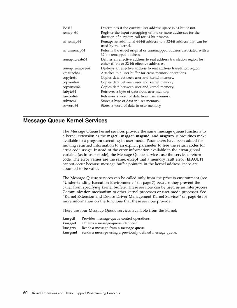
IS64U Determines if the current user address space is 64-bit or not.
remap_64 Register the input remapping of one or more addresses for theduration of a system call for 64-bit process.
as_remap64 Remaps an additional 64-bit address to a 32-bit address that can beused by the kernel.
as_unremap64 Returns the 64-bit original or unremapped address associated with a32-bit remapped address.
rnmap_create64 Defines an effective address to real address translation region foreither 64-bit or 32-bit effective addresses.
rnmap_remove64 Destroys an effective address to real address translation region.
xmattach64 Attaches to a user buffer for cross-memory operations.
copyin64 Copies data between user and kernel memory.
copyout64 Copies data between user and kernel memory.
copyinstr64 Copies data between user and kernel memory.
fubyte64 Retrieves a byte of data from user memory.
fuword64 Retrieves a word of data from user memory.
subyte64 Stores a byte of data in user memory.
suword64 Stores a word of data in user memory.
Message Queue Kernel Services
The Message Queue kernel services provide the same message queue functions toa kernel extension as the msgctl, msgget, msgsnd, and msgxrcv subroutines makeavailable to a program executing in user mode. Parameters have been added formoving returned information to an explicit parameter to free the return codes forerror code usage. Instead of the error information available in the errno globalvariable (as in user mode), the Message Queue services use the service’s returncode. The error values are the same, except that a memory fault error (EFAULT)cannot occur because message buffer pointers in the kernel address space areassumed to be valid.
The Message Queue services can be called only from the process environment (see“Understanding Execution Environments” on page 7) because they prevent thecaller from specifying kernel buffers. These services can be used as an InterprocessCommunication mechanism to other kernel processes or user-mode processes. See“Kernel Extension and Device Driver Management Kernel Services” on page 46 formore information on the functions that these services provide.
There are four Message Queue services available from the kernel:
kmsgctl Provides message-queue control operations.
kmsgget Obtains a message-queue identifier.
kmsgrcv Reads a message from a message queue.
kmsgsnd Sends a message using a previously defined message queue.
60 Kernel Extensions and Device Support Programming Concepts

Network Kernel Services
The Network kernel services are divided into:
v “Address Family Domain and Network Interface Device Driver Kernel Services”
v “Routing and Interface Address Kernel Services” on page 62
v “Loopback Kernel Services” on page 62
v “Protocol Kernel Services” on page 62
v “Communications Device Handler Interface Kernel Services” on page 63
Address Family Domain and Network Interface Device DriverKernel Services
The Address Family Domain and Network Interface Device Driver services enableaddress family domains (Protocols) and network interface drivers to add andremove themselves from network switch tables.
The if_attach service and if_detach services add and remove network interfacesfrom the Network Interface List. Protocols search this list to determine anappropriate interface on which to transmit a packet.
Protocols use the add_input_type and del_input_type services to notify networkinterface drivers that the protocol is available to handle packets of a certain type.The Network Interface Driver uses the find_input_type service to distributepackets to a protocol.
The add_netisr and del_netisr services add and delete network software interrupthandlers. Address families add and delete themselves from the Address FamilyDomain switch table by using the add_domain_af and del_domain_af services.The Address Family Domain switch table is a list of all available protocols that canbe used in the socket subroutine.
The Address Family Domain and Network Interface Device Driver services are:
add_domain_af Adds an address family to the Address Family domain switchtable.
add_input_type Adds a new input type to the Network Input table.
add_netisr Adds a network software interrupt service to the NetworkInterrupt table.
del_domain_af Deletes an address family from the Address Family domain switchtable.
del_input_type Deletes an input type from the Network Input table.
del_netisr Deletes a network software interrupt service routine from theNetwork Interrupt table.
find_input_type Finds the given packet type in the Network Input Interface switchtable and distributes the input packet according to the table entryfor that type.
if_attach Adds a network interface to the network interface list.
if_detach Deletes a network interface from the network interface list.
ifunit Returns a pointer to the ifnet structure of the requested interface.
schednetisr Schedules or invokes a network software interrupt service routine.
Chapter 4. Kernel Services 61

Routing and Interface Address Kernel Services
The Routing and Interface Address services provide protocols with a means ofestablishing, accessing, and removing routes to remote hosts or gateways. Routesbind destinations to a particular network interface.
The interface address services accept a destination address or network and returnan associated interface address. Protocols use these services to determine if anaddress is on a directly connected network.
The Routing and Interface Address services are:
ifa_ifwithaddr Locates an interface based on a complete address.
ifa_ifwithdstaddr Locates the point-to-point interface with a given destinationaddress.
ifa_ifwithnet Locates an interface on a specific network.
if_down Marks an interface as down.
if_nostat Zeroes statistical elements of the interface array in preparationfor an attach operation.
rtalloc Allocates a route.
rtfree Frees the routing table entry
rtinit Sets up a routing table entry, typically for a network interface.
rtredirect Forces a routing table entry with the specified destination to gothrough the given gateway.
rtrequest Carries out a request to change the routing table.
Loopback Kernel Services
The Loopback services enable networking code to be exercised without actuallytransmitting packets on a network. This is a useful tool for developing newprotocols without introducing network variables. Loopback services can also beused to send packets to local addresses without using hardware loopback.
The Loopback services are:
loifp Returns the address of the software loopback interface structure.
looutput Sends data through a software loopback interface.
Protocol Kernel Services
Protocol kernel services provide a means of finding a particular address family aswell as a raw protocol handler. The raw protocol handler basically passes rawpackets up through sockets so that a protocol can be implemented in user space.
The Protocol kernel services are:
pfctlinput Starts the ctlinput function for each configured protocol.
pffindproto Returns the address of a protocol switch table entry.
raw_input Builds a raw_header structure for a packet and sends both to the rawprotocol handler.
raw_usrreq Implements user requests for raw protocols.
62 Kernel Extensions and Device Support Programming Concepts

Communications Device Handler Interface Kernel Services
The Communications Device Handler Interface services provide a standardinterface between network interface drivers and communications device handlers(see “Communications Physical Device Handler Model Overview” on page 100).The net_attach and net_detach services open and close the device handler. Oncethe device handler has been opened, the net_xmit service can be used to transmitpackets. Asynchronous start done notifications are recorded by the net_start_doneservice. The net_error service handles error conditions.
The Communications Device Handler Interface services are:
add_netopt This macro adds a network option structure to the list of networkoptions.
del_netopt This macro deletes a network option structure from the list ofnetwork options.
net_attach Opens a communications I/O device handler.
net_detach Closes a communications I/O device handler.
net_error Handles errors for communication network interface drivers.
net_sleep Sleeps on the specified wait channel.
net_start Starts network IDs on a communications I/O device handler.
net_start_done Starts the done notification handler for communications I/O devicehandlers.
net_wakeup Wakes up all sleepers waiting on the specified wait channel.
net_xmit Transmits data using a communications I/O device handler.
net_xmit_trace Traces transmit packets. This kernel service was added for thosenetwork interfaces that do not use the net_xmit kernel service totrace transmit packets.
Process and Exception Management Kernel Services
The process and exception management kernel services provided by the basekernel provide the capability to:
v “Introduction to Kernel Processes” on page 11
v “Understanding Exception Handling” on page 18
v Provide process serialization
v Generate and handle signals
v Support event waiting and notification
Creating Kernel ProcessesKernel extensions use the creatp and initp kernel services to create and intialize akernel process (see “Introduction to Kernel Processes” on page 11). The setpinitkernel service allow a kernel process to change its parent process from the one thatcreated it to the init process, so that the creating process does not receive thedeath-of-child process signal upon kernel process termination. “Using KernelProcesses” on page 11 supplies additional information concerning use of theseservices.
Creating Kernel ThreadsKernel extensions use the thread_create and kthread_start services to create andinitialize kernel-only threads. “Understanding Kernel Threads” on page 9 providesmore information about threads.
Chapter 4. Kernel Services 63
The thread_setsched service is used to control the scheduling parameters, priorityand scheduling policy, of a thread.
Kernel Structures EncapsulationThe getpid kernel service is used by a kernel extension in either the process orinterrupt environment to determine the current execution environment (see“Understanding Execution Environments” on page 7) and obtain the process ID ofthe current process if in the process environment. The rusage_incr service providesan access to the rusage structure.
The thread-specific uthread structure is also encapsulated. The getuerror andsetuerror kernel services should be used to access the ut_error field. Thethread_self kernel service should be used to get the current thread’s ID.
Registering Exception HandlersThe setjmpx, clrjmpx, and longjmpx kernel services allow a kernel extension toregister an exception handler by:
v Saving the exception handler’s context with the setjmpx kernel service
v Removing its saved context with the clrjmpx kernel service if no exceptionoccurred
v Starting the next registered exception handler with the longjmpx kernel serviceif it was unable to handle the exception
Refer to “Handling Exceptions While in a System Call” on page 29 for additionalinformation concerning use of these services.
Signal ManagementSignals can be posted either to a kernel process or to a kernel thread. The pidsigservice posts a signal to a specified kernel process; the kthread_kill service posts asignal to a specified kernel thread. A thread uses the sig_chk service to poll forsignals delivered to the kernel process or thread in the kernel mode.
“Kernel Process Signal and Exception Handling” on page 14 provides moreinformation about signal management.
Events ManagementThe event notification services provide support for two types of interprocesscommunications:
Primitive Allows only one process thread waiting on the event.
Shared Allows multiple processes threads waiting on the event.
The et_wait and et_post kernel services support single waiter event notification byusing mutually agreed upon event control bits for the kernel thread being posted.There are a limited number of control bits available for use by kernel extensions. Ifthe kernel_lock is owned by the caller of the et_wait service, it is released andacquired again upon wakeup.
The following kernel services support a shared event notification mechanism thatallows for multiple threads to be waiting on the shared event.
e_assert_wait e_wakeup
e_block_thread e_wakeup_one
64 Kernel Extensions and Device Support Programming Concepts

e_clear_wait e_wakeup_w_result
e_sleep_thread e_wakeup_w_sig
These services support an unlimited number of shared events (by usingcaller-supplied event words). The following list indicates methods to wait for anevent to occur:
v Calling e_assert_wait and e_block_thread successively; the first call puts thethread on the event queue, the second blocks the thread. Between the two calls,the thread can do any job, like releasing several locks. If only one lock, or nolock at all, needs to be released, one of the two other methods should beprefered.
v Calling e_sleep_thread; this service releases a simple or a complex lock, andblocks the thread. The lock can be automatically reacquired at wakeup.
The e_clear_wait service can be used by a thread or an interrupt handler to wakeup a specified thread, or by a thread that called e_assert_wait to remove itselffrom the event queue without blocking when calling e_block_thread. The otherwakeup services are event-based. The e_wakeup and e_wakeup_w_result serviceswake up every thread sleeping on an event queue; while the e_wakeup_oneservice wakes up only the most favored thread. The e_wakeup_w_sig service postsa signal to every thread sleeping on an event queue, waking up all the threadswhose sleep is interruptible.
The e_sleep and e_sleepl kernel services are provided for code that was writtenfor previous releases of the operating system. Threads which have called one ofthese services are woken up by the e_wakeup, e_wakeup_one,e_wakeup_w_result, e_wakeup_w_sig, or e_clear_wait kernel services. If the callerof the e_sleep service owns the kernel lock, it is released before waiting and isacquired again upon wakeup. The e_sleepl service provides the same function asthe e_sleep service except that a caller-specified lock is released and acquired againinstead of the kernel_lock.
List of Process, Thread, and Exception Management KernelServices
The Process, Thread, and Exception Management kernel services are listed below.
clrjmpx Removes a saved context by popping the most recently savedjump buffer from the list of saved contexts.
creatp Creates a new kernel process.
e_assert_wait Asserts that the calling kernel thread is going to sleep.
e_block_thread Blocks the calling kernel thread.
e_clear_wait Clears the wait condition for a kernel thread.
e_sleep, e_sleep_thread,or e_sleepl
Forces the calling kernel thread to wait for the occurrence of ashared event.
e_sleep_thread Forces the calling kernel thread to wait the occurrence of ashared event.
e_wakeup,e_wakeup_one, ore_wakeup_w_result
Notifies kernel threads waiting on a shared event of the event’soccurrence.
e_wakeup_w_sig Posts a signal to sleeping kernel threads.
et_post Notifies a kernel thread of the occurrence of one or more events.
et_wait Forces the calling kernel thread to wait for the occurrence of anevent.
getpid Gets the process ID of the current process.
Chapter 4. Kernel Services 65

getppidx Gets the parent process ID of the specified process.
initp Changes the state of a kernel process from idle to ready.
kthread_kill Posts a signal to a specified kernel-only thread.
kthread_start Starts a previously created kernel-only thread.
limit_sigs Changes the signal mask for the calling kernel thread.
longjmpx Allows exception handling by causing execution to resume atthe most recently saved context.
NLuprintf Submits a request to print an internationalized message to thecontrolling terminal of a process.
pgsignal Sends a signal to a process group.
pidsig Sends a signal to a process.
rusage_incr Increments a field of the rusage structure.
setjmpx Allows saving the current execution state or context.
setpinit Sets the parent of the current kernel process to the init process.
sig_chk Provides the calling kernel thread with the ability to poll forreceipt of signals.
sigsetmask Changes the signal mask for the calling kernel thread.
sleep Forces the calling kernel thread to wait on a specified channel.
thread_create Creates a new kernel-only thread in the calling process.
thread_self Returns the caller’s kernel thread ID.
thread_setsched Sets kernel thread scheduling parameters.
thread_terminate Terminates the calling kernel thread.
uprintf Submits a request to print a message to the controlling terminalof a process.
RAS Kernel Services
The Reliability, Availability, and Serviceability (RAS) kernel services are used torecord the occurrence of hardware or software failures and to capture data aboutthese failures. The recorded information can be examined using the errpt, trcrpt, orcrash commands.
The panic kernel service is called when a catastrophic failure occurs and thesystem can no longer operate. The panic service performs a system dump. Thesystem dump captures data areas that are registered in the Master Dump Table.The kernel and kernel extensions use the dmp_add kernel service to add an entryto the Master Dump Table and the dmp_del kernel service to remove an entry.
The errsave and errlast kernel service is called to record an entry in the systemerror log when a hardware or software failure is detected.
The trcgenk and trcgenkt kernel services are used along with the trchooksubroutine to record selected system events in the event-tracing facility.
List of RAS Kernel ServicesThe RAS kernel services are:
dmp_add Specifies data to be included in a system dump by adding anentry to the master dump table.
dmp_del Deletes an entry from the master dump table.
dmp_prinit Initializes the remote dump protocol.
errsave and errlast Allows the kernel and kernel extensions to write to the errorlog.
panic Crashes the system.
66 Kernel Extensions and Device Support Programming Concepts
trcgenk Records a trace event for a generic trace channel.
trcgenkt Records a trace event, including a time stamp, for a generictrace channel.
Security Kernel Services
The Security kernel services provide methods for controlling the auditing systemand for determining the access rights to objects for the invoking process.
The following services are Security kernel services:
suser Determines the privilege state of a process.
audit_svcstart Initiates an audit record for a kernel service.
audit_svcbcopy Appends event information to the current audit event buffer.
audit_svcfinis Writes an audit record for a kernel service.
Timer and Time-of-Day Kernel Services
The Timer and Time-of-Day kernel services provide kernel extensions with theability to be notified when a period of time has passed. The tstart service supportsa very fine granularity of time. The timeout service is built on the tstart serviceand is provided for compatibility with earlier versions of the operating system. Thew_start service provides a timer with less granularity, but much cheaperpath-length overhead when starting a timer.
Time-Of-Day Kernel ServicesThe Time-Of-Day kernel services are:
curtime Reads the current time into a time structure.
kgettickd Retrieves the current status of the systemwide time-of-day timer-adjustmentvalues.
ksettimer Sets the systemwide time-of-day timer.
ksettickd Sets the current status of the systemwide timer-adjustment values.
Fine Granularity Timer Kernel Services
The Fine Granularity Timer kernel services are:
delay Suspends the calling process for the specified number of timer ticks.
talloc Allocates a timer request block before starting a timer request.
tfree Deallocates a timer request block.
tstart Submits a timer request.
tstop Cancels a pending timer request.
You can find additional information about using the Fine Granularity Timerservices in “Using Fine Granularity Timer Services and Structures” on page 68.
Chapter 4. Kernel Services 67

Timer Kernel Services for Compatibility
The following Timer kernel services are provided for compatibility:
timeout Schedules a function to be called after a specified interval.
timeoutcf Allocates or deallocates callout table entries for use with the timeout kernelservice.
untimeout Cancels a pending timer request.
Watchdog Timer Kernel Services
The Watchdog timer kernel services are:
w_clear Removes a watchdog timer from the list of watchdog timers known to thekernel.
w_init Registers a watchdog timer with the kernel.
w_start Starts a watchdog timer.
w_stop Stops a watchdog timer.
Using Fine Granularity Timer Services and Structures
The tstart, tfree, talloc, and tstop services provide fine-resolution timing functions.These timer services should be used when the following conditions are required:
v Timing requests for less than one second
v Critical timing
v Absolute timing
The Watchdog timer services can be used for noncritical times having a one-secondresolution. The timeout service can be used for noncritical times having aclock-tick resolution.
Timer Services Data Structures
The trb (timer request) structure is found in the /sys/timer.h file. The itimerstruc_tstructure contains the second/nanosecond structure for time operations and isfound in the sys/time.h file.
The itimerstruc_t t.it value substructure should be used to store time informationfor both absolute and incremental timers. The T_ABSOLUTE absolute request flagis defined in the sys/timer.h file. It should be ORed into the t->flag field if anabsolute timer request is desired.
The T_LOWRES flag causes the system to round the t->timeout value to the nexttimer timeout. It should be ORed into the t->flags field. The timeout is alwaysrounded to a larger value. Since the system maintains 10ms interval timer,T_LOWRES will never cause more than 10ms to be added to a timeout. Theadvantage of using T_LOWRES is that it prevents an extra interrupt from beinggenerated.
The t->timeout and t->flags fields must be set or reset before each call to thetstart kernel service.
68 Kernel Extensions and Device Support Programming Concepts

Coding the Timer Function
The t->func timer function should be declared as follows:
void func (t)struct trb *t;
The argument to the func completion handler routine is the address of the trbstructure, not the contents of the t_union field.
The t->func timer function is called on an interrupt level. Therefore, code for thisroutine must follow conventions for interrupt handlers.
Using Multiprocessor-Safe Timer Services
On a multiprocessor system, timer request blocks and watchdog timer structurescould be accessed simultaneously by several processors. The kernel services shownbelow potentially alter critical information in these blocks and structures, andtherefore check whether it is safe to perform the requested service beforeproceeding:
tstop Cancels a pending timer request.
w_clear Removes a watchdog timer from the list of watchdog timers known to thekernel.
w_init Registers a watchdog timer with the kernel.
If the requested service cannot be performed, the kernel service returns an errorvalue.
In order to be multiprocessor safe, the caller must check the value returned bythese kernel services. If the service was not successful, the caller must take anappropriate action, for example, retrying in a loop. If the caller holds a devicedriver lock, it should release and then reacquire the lock within this loop in orderto avoid deadlock.
Drivers which were written for uniprocessor systems do not check the returnvalues of these kernel services and are not multiprocessor-safe. Such drivers canstill run as funnelled device drivers.
Virtual File System (VFS) Kernel Services
The Virtual File System (VFS) kernel services are provided as fundamental buildingblocks for use when writing a virtual file system. These services present a standardinterface for such functions as configuring file systems, creating and freeingv-nodes, and looking up path names.
Most functions involved in the writing of a file system are specific to that filesystem type. But a limited number of functions must be performed in a consistentmanner across the various file system types to enable the logical file system tooperate independently of the file system type.
The VFS kernel services are:
common_relock Implements a generic interface to the byte range locking functions.
fidtovp Maps a file system structure to a file ID.
Chapter 4. Kernel Services 69
gfsadd Adds a file system type to the gfs table.
gfsdel Removes a file system type from the gfs table.
vfs_hold Holds a vfs structure and increments the structure’s use count.
vfs_unhold Releases a vfs structure and decrements the structure’s use count.
vfsrele Releases all resources associated with a virtual file system.
vfs_search Searches the vfs list.
vn_free Frees a v-node previously allocated by the vn_get kernel service.
vn_get Allocates a virtual node and associates it with the designated virtualfile system.
lookupvp Retrieves the v-node that corresponds to the named path.
70 Kernel Extensions and Device Support Programming Concepts

Chapter 5. Asynchronous I/O Subsystem
The following topics pertain to Asynchronous I/O:
v “Asynchronous I/O Overview”
v “Prerequisites” on page 73
v “Functions of Asynchronous I/O” on page 73
v “Asynchronous I/O Subroutines” on page 75
v “Subroutines Affected by Asynchronous I/O” on page 76
v “Changing Attributes for Asynchronous I/O” on page 76
v “64-bit Enhancements” on page 77
Asynchronous I/O Overview
Synchronous I/O occurs while you wait. Applications processing cannot continueuntil the I/O operation is complete.
In contrast, asynchronous I/O operations run in the background and do not blockuser applications. This improves performance, because I/O operations andapplications processing can run simultaneously.
Using asynchronous I/O will usually improve your I/O throughput, especiallywhen you are storing data in raw logical volumes (as opposed to Journaled filsystems). The actual performance, however, depends on how many serverprocesses are running that will handle the I/O requests.
Many applications, such as databases and file servers, take advantage of the abilityto overlap processing and I/O. These asynchronous I/O operations use variouskinds of devices and files. Additionally, multiple asynchronous I/O operations mayrun at the same time on one or more devices or files.
Each asynchronous I/O request has a corresponding control block in theapplication’s address space. When an asynchronous I/O request is made, a handleis established in the control block. This handle is used to retrieve the status and thereturn values of the request.
Applications use the aio_read and aio_write subroutines to perform the I/O.Control returns to the application from the subroutine, as soon as the request hasbeen queued. The application can then continue processing while the diskoperation is being performed.
A kernel process (KPROC), called a server, is in charge of each request from thetime it is taken off the queue until it completes. The number of servers limits thenumber of disk I/O operations that can be in progress in the systemsimultaneously.
The default values are minservers=1 and maxservers=10. In systems that seldomrun applications that use asynchronous I/O, this is usually adequate. Forenvironments with many disk drives and key applications that use asynchronousI/O, the default is far too low. The result of a deficiency of servers is that disk I/Oseems much slower than it should be. Not only do requests spend inordinate
© Copyright IBM Corp. 1997, 1999 71

lengths of time in the queue, but the low ratio of servers to disk drives means thatthe seek-optimization algorithms have too few requests to work with for eachdrive.
How do I know if I need to use AIO?Using the vmstat command with an interval and count value, you can determine ifthe CPU is idle waiting for disk I/O. The wa column details the percentage of timethe CPU was idle with pending local disk I/O.
If there is at least one outstanding I/O to a local disk when the wait process isrunning, the time is classified as waiting for I/O. Unless asynchronous I/O isbeing used by the process, an I/O request to disk causes the calling process toblock (or sleep) until the request has been completed. Once a process’s I/O requestcompletes, it is placed on the run queue.
A wa value consistently over 25 percent may indicate that the disk subsystem is notbalanced properly, or it may be the result of a disk-intensive workload.
Note: AIO will not relieve an overly busy disk drive. Using the iostatcommand with an interval and count value, you can determine if any disksare overly busy. Monitor the %tm_act column for each disk drive on thesystem. On some systems, a %tm_act of 35.0 or higher for one disk can causenoticeably slower performance. The relief for this case could be to move datafrom more busy to less busy disks, but simply having AIO will not relieve anoverly busy disk problem.
Important for SMPFor SMP systems, the us, sy, id and wa columns are only averages over allprocessors. But keep in mind that the I/O wait statistic per processor is not reallya processor-specific statistic; it is a global statistic. An I/O wait is distinguishedfrom idle time only by the state of a pending I/O. If there is any pending diskI/O, and the processor is not busy, then it is an I/O wait time. Disk I/O is nottracked by processors, so when there is any I/O wait, all processors get charged(assuming they are all equally idle).
How many AIO Servers am I currently using?The following command will tell you how many AIO Servers are currently running(you must run this command as the ″root″ user):
pstat -a | grep aios | wc -l
If the disk drives that are being accessed asynchronously are using the AIXJournaled File System (JFS), all I/O will be routed through the aios KPROCs.
If the disk drives that are being accessed asynchronously are using a form of RAWlogical volume management, then the disk I/O is not routed through the aiosKPROCs. In that case the number of servers running is not relevant.
However, if you want to confirm that an application that uses RAW logic volumesis taking advantage of AIO, and you are at AIX 4.3.2 or AIX 4.3.x with APARIX79690 installed, you can disable the ″Fastpath″ option via SMIT. When thisoption has been disabled, even RAW I/O will be forced through the aios KPROCs.At that point, the pstat command listed in preceding discussion will work. Youwould not want to run the system with this option disabled for any length of time.This is simply a suggestion to confirm that the application is working with AIOand RAW logical volumes.
72 Kernel Extensions and Device Support Programming Concepts

At AIX levels before AIX 4.3, the ″Fastpath″ is enabled by default and cannot bedisabled.
How many AIO servers do I need?Here are some suggested rules of thumb for determining what value to setMAXIMUM number of servers to:
1. The first rule of thumb suggests that you limit the MAXIMUM number ofservers to a number equal to ten times the number of disks that are to be usedconcurrently, but not more than 80. The MINIMUM number of servers shouldbe set to half of this maximum number.
2. Another rule of thumb is to set the MAXIMUM number of servers to 80 andleave the MINIMUM number of servers set to the default of 1 and reboot.Monitor the number of additional servers started throughout the course ofnormal workload. After a 24-hour period of normal activity, set the MAXIMUMnumber of servers to:
(The number of currently running aios + 10),
and set the MINIMUM number of servers to:
(The number of currently running aios - 10).
In some environments you may see more than 80 aios KPROCs running. If so,consider this rule of thumb:
3. A third suggestion is to take statistics using vmstat -s before any high I/Oactivity begins, and again at the end. Check the field iodone. From this you candetermine how many physical I/Os are being handled in a given wall clockperiod. Then increase the MAXIMUM number of servers and see if you can getmore iodones in the same time period.
Prerequisites
To make use of asynchronous I/O the following fileset must be installed:
bos.rte.aio
To determine if this fileset is installed, use:
lslpp -l bos.rte.aio
You must also make the aio0 device ″Available″ via SMIT.
smit chgaioSTATE to be configured at system restart available
Functions of Asynchronous I/O
Functions provided by the asynchronous I/O facilities are:
v “Large File-Enabled Asynchronous I/O (AIX Version 4.2.1 or later)”
v “Nonblocking I/O” on page 74
v “Notification of I/O Completion” on page 74
v “Cancellation of I/O Requests” on page 75
Large File-Enabled Asynchronous I/O (AIX Version 4.2.1 orlater)
The fundamental data structure associated with all asynchronous I/O operations isstruct aiocb. Within this structure is the aio_offset field which is used to specifythe offset for an I/O operation.
Chapter 5. Asynchronous I/O Subsystem 73

The default asynchronous I/O interfaces are limited to an offset of 2G minus 1 dueto the signed 32-bit definition of aio_offset. To overcome this limitation, a newaio control block with a signed 64-bit offset field and a new set of asynchronousI/O interfaces have been defined beginning with AIX Version 4.2.1.
The large offset-enabled asynchronous I/O interfaces are available under the_LARGE_FILES compilation environment and under the _LARGE_FILE_APIprogramming environment. For further information, see Writing Programs ThatAccess Large Files in AIX Version 4.3 General Programming Concepts: Writing andDebugging Programs.
Under the _LARGE_FILES compilation environment in AIX Version 4.2.1 or later,asynchronous I/O applications written to the default interfaces see the followingredefinitions:
Item Redefined To Be Header File
struct aiocb struct aiocb64 sys/aio.h
aio_read() aio_read64() sys/aio.h
aio_write() aio_write64() sys/aio.h
aio_cancel() aio_cancel64() sys/aio.h
aio_suspend() aio_suspend64() sys/aio.h
aio_listio() aio_listio() sys/aio.h
aio_return() aio_return64() sys/aio.h
aio_error() aio_error64() sys/aio.h
For information on using the _LARGE_FILES environment, see PortingApplications to the Large File Environment in AIX Version 4.3 General ProgrammingConcepts: Writing and Debugging Programs
In the _LARGE_FILE_API environment, the 64-bit API interfaces are visible. Thisenvironment requires recoding of applications to the new 64-bit API name. Forfurther information on using the _LARGE_FILE_API environment, see Using the64-Bit File System Subroutines in AIX Version 4.3 General Programming Concepts:Writing and Debugging Programs
Nonblocking I/OAfter issuing an I/O request, the user application can proceed without beingblocked while the I/O operation is in progress. The I/O operation occurs while theapplication is running. Specifically, when the application issues an I/O request, therequest is queued. The application can then resume running before the I/Ooperation is initiated.
To manage asynchronous I/O, each asynchronous I/O request has a correspondingcontrol block in the application’s address space. This control block contains thecontrol and status information for the request. It can be used again when the I/Ooperation is completed.
Notification of I/O CompletionAfter issuing an asynchronous I/O request, the user application can determinewhen and how the I/O operation is completed. This information is provided inthree ways:
74 Kernel Extensions and Device Support Programming Concepts

v The application can poll the status of the I/O operation (see “Polling the Statusof the I/O Operation”).
v The system can asynchronously notify the application when the I/O operation isdone (see “Asynchronously Notifying the Application When the I/O OperationCompletes”).
v The application can block until the I/O operation is complete (see “Blocking theApplication until the I/O Operation Is Complete”).
Polling the Status of the I/O OperationThe application can periodically poll the status of the I/O operation. The status ofeach I/O operation is provided in the application’s address space in the controlblock associated with each request. Portable applications can retrieve the status byusing the aio_error subroutine.
Asynchronously Notifying the Application When the I/OOperation CompletesAsynchronously notifying the I/O completion is done by signals. Specifically, anapplication may request that a SIGIO signal be delivered when the I/O operationis complete. To do this, the application sets a flag in the control block at the time itissues the I/O request. If several requests have been issued, the application canpoll the status of the requests to determine which have actually completed.
Blocking the Application until the I/O Operation Is CompleteThe third way to determine whether an I/O operation is complete is to let thecalling process become blocked and wait until at least one of the I/O requests it iswaiting for is complete. This is similar to synchronous style I/O. It is useful forapplications that, after performing some processing, need to wait for I/Ocompletion before proceeding.
Cancellation of I/O RequestsI/O requests can be canceled if they are cancelable. Cancellation is not guaranteedand may succeed or not depending upon the state of the individual request. If arequest is in the queue and the I/O operations have not yet started, the request iscancellable. Typically, a request is no longer cancelable when the actual I/Ooperation has begun.
Asynchronous I/O Subroutines
Note: The 64-bit APIs are available beginning with AIX Version 4.2.1.
The following subroutines are provided for performing asynchronous I/O:
Subroutine Purpose
aio_cancel or aio_cancel64 Cancels one or more asynchronous I/Orequests.
aio_error or aio_error64 Retrieves the error status of an I/O request.
lio_listio or lio_listio64 Initiates multiple asynchronous read and writeoperations.
aio_read or aio_read64 Reads asynchronously from a file.
aio_return or aio_return64 Retrieves the return value of an I/O request.
aio_suspend or aio_suspend64 Blocks until an asynchronous I/O is completed.
aio_write or aio_write64 Writes asynchronously to a file.
Note: These subroutines may change to conform with the IEEE POSIX 1003.4interface specification.
Chapter 5. Asynchronous I/O Subsystem 75

Order and Priority of Asynchronous I/O CallsAn application may issue several asynchronous I/O requests on the same file ordevice. However, since the I/O operations are performed asynchronously, the orderin which they are handled may not be the order in which the I/O calls were made.The application must enforce ordering of its own I/O requests if ordering isrequired.
Priority among the I/O requests is not currently implemented. The aio_reqpriofield in the control block is currently ignored.
For files that support seek operations, seeking is allowed as part of theasynchronous read or write operations. The whence and offset fields are providedin the control block of the request to set the seek parameters. The seek pointer isupdated when the asynchronous read or write call returns.
Subroutines Affected by Asynchronous I/O
The following existing subroutines are affected by asynchronous I/O:
v The close subroutine
v The exit subroutine
v The exec subroutine
v The fork subroutine
If the application closes a file, or calls the _exit or exec subroutines while it hassome outstanding I/O requests, the requests are canceled. If they cannot becanceled, the application is blocked until the requests have completed. When aprocess calls the fork subroutine, its asynchronous I/O is not inherited by the childprocess.
One fundamental limitation in asynchronous I/O is page hiding. When anunbuffered (raw) asynchronous I/O is issued, the page that contains the userbuffer is hidden during the actual I/O operation. This ensures cache consistency.However, the application may access the memory locations that fall within thesame page as the user buffer. This may cause the application to block as a result ofa page fault. To alleviate this, allocate page aligned buffers and do not touch thebuffers until the I/O request using it has completed.
Changing Attributes for Asynchronous I/O
You can change attributes relating to asynchronous I/O using the chdev commandor SMIT. Likewise, you can use SMIT to configure and remove (unconfigure)asynchronous I/O. (Alternatively, you can use the mkdev and rmdev commandsto configure and remove asynchronous I/O). To start SMIT at the main menu forasynchronous I/O, enter smit aio.
MINIMUM number of serversindicates the minimum number of kernel processes dedicated toasynchronous I/O processing. Since each kernel process uses memory, thisnumber should not be large when the amount of asynchronous I/Oexpected is small.
MAXIMUM number of serversindicates the maximum number of kernel processes dedicated to
76 Kernel Extensions and Device Support Programming Concepts
asynchronous I/O processing. There can never be more than this manyasynchronous I/O requests in progress at one time, so this number limitsthe possible I/O concurrency.
Maximum number of REQUESTSindicates the maximum number of asynchronous I/O requests that can beoutstanding at one time. This includes requests that are in progress as wellas those that are waiting to be started. The maximum number ofasynchronous I/O requests cannot be less than the value of AIO_MAX, asdefined in the /usr/include/sys/limits.h file, but it can be greater. It wouldbe appropriate for a system with a high volume of asynchronous I/O tohave a maximum number of asynchronous I/O requests larger thanAIO_MAX.
Server PRIORITYindicates the priority level of kernel processes dedicated to asynchronousI/O. The lower the priority number is, the more favored the process is inscheduling. Concurrency is enhanced by making this number slightly lessthan the value of PUSER, the priority of a normal user process. It cannotbe made lower than the values of PRI_SCHED.
Since the default priority is (40+nice), these daemons will be slightlyfavored with this value of (39+nice). If you want to favor them more, mchanges slowly. A very low priority can interfere with the system processthat require low priority.
Attention: Raising the server PRIORITY (decreasing this numericvalue) is not recommended. The system can hang or crash.
PUSER and PRI_SCHED are defined in the /usr/include/sys/pri.h file.
STATE to be configured at system restartindicates the state to which asynchronous I/O is to be configured duringsystem initialization. The possible values are 1.) defined, which indicatesthat the asynchronous I/O will be left in the defined state and notavailable for use, and 2.) available, indicating that asynchronous I/O willbe configured and available for use.
STATE of FastPathYou will only see this option if you are at AIX 4.3.2 or any level of AIX4.3.x with APAR IX79690 installed. Disabling this option forces ALL I/Oactivity through the aios KPROCs, even I/O activity involving RAW logicalvolumes. At AIX levels before AIX 4.3 the ″Fastpath″ is enabled by defaultand cannot disabled.
64-bit Enhancements
Asynchronous I/O (AIO) has been enhanced to support 64-bit enabledapplications. On 64-bit platforms, both 32-bit and 64-bit AIO can occursimultaneously.
The struct aiocb, the fundamental data structure associated with all asynchronousI/O operation, has changed. The element of this struct, aio_return, is now definedas ssize_t. Previously, it was defined as an int. AIO supports large files bydefault. An application compiled in 64-bit mode can do AIO to a large file withoutany additional #defines or special opening of those files.
Chapter 5. Asynchronous I/O Subsystem 77

78 Kernel Extensions and Device Support Programming Concepts
Chapter 6. Device Configuration Subsystem
Devices are usually pieces of equipment that attach to a computer. Devices includeprinters, adapters, and disk drives. Additionally, devices are special files that canhandle device-related tasks.
System users cannot operate devices until device configuration occurs. To configuredevices, the Device Configuration Subsystem is available.
v “Scope of Device Configuration Support”
v “Device Configuration Subsystem Overview”
v “General Structure of the Device Configuration Subsystem” on page 80
Scope of Device Configuration Support
The term device has a wider range of meaning in this operating system than intraditional operating systems. Traditionally, devices refers to hardware componentssuch as disk drives, tape drives, printers, and keyboards. Pseudo-devices, such asthe console, error special file, and null special file, are also included in thiscategory. However, in this operating system, all of these devices are referred to askernel devices, which have device drivers and are known to the system by majorand minor numbers.
Also, in this operating system, hardware components such as buses, adapters, andenclosures (including racks, drawers, and expansion boxes) are considered devices.
Device Configuration Subsystem Overview
Devices are organized hierarchically within the system. This organization requireslower-level device dependence on upper-level devices in child-parent relationships.The system device (sys0) is the highest-level device in the system node, whichconsists of all physical devices in the system.
Each device is classified into functional classes, functional subclasses and devicetypes (for example, printer class, parallel subclass, 4201 Proprinter type). Theseclassifications are maintained in the device configuration databases with all otherdevice information.
A DDS (device dependent structure) is a structure provided to communicate adevice’s characteristics from a Configure method to a device driver. The device’sDDS is built each time the device is configured (Configure method).
© Copyright IBM Corp. 1997, 1999 79
The Device Configuration Subsystem consists of:
High-level Commands Maintain (add, delete, view, change) configured deviceswithin the system. These commands manage all of theconfiguration functions and are performed by invoking theappropriate device methods for the device being configured.These commands call device methods and low-levelcommands.
The system uses the high-level Configuration Manager(cfgmgr) command used to invoke automatic deviceconfigurations through system boot phases and the user caninvoke the command during system run time. Configurationrules govern the cfgmgr command.
Device Methods Define and configure, start and stop devices. The devicemethods are used to identify or change the device states(operational modes). Device methods can call low-levelcommands.
Low-level Commands Perform routines and functions common to all devices (e.g., toupdate device attribute information).
Database Maintains data through the ODM (Object Data Manager) byobject classes. Predefined Device Objects contain configurationdata for all devices that can possibly be used by the system.Customized Device Objects contain data for device instancesthat are actually in use by the system.
General Structure of the Device Configuration Subsystem
The Device Configuration Subsystem can be viewed from three different levels:
v High-level perspective
v Device method level
v Low-level perspective
Data that is used by the three levels is maintained in the configuration database (see“Device Configuration Database Overview” on page 84). The database is managedas object classes by the Object Data Manager (ODM). All information relevant tosupport the device configuration process is stored in the configuration database.
The system cannot use any device unless it is configured.
The database has two components: the Predefined database and the Customizeddatabase. The Predefined database contains configuration data for all devices thatcould possibly be supported by the system. The Customized database containsconfiguration data for the devices actually defined and configured in thatparticular system.
The configuration manager (cfgmgr command) performs the configuration of asystem’s devices automatically when the system is booted (see “DeviceConfiguration Manager Overview” on page 85). This high-level program can alsobe invoked through the system keyboard to perform automatic deviceconfiguration. The configuration manager command configures devices as specifiedby Configuration rules.
These components are illustrated in the Components Involved in DeviceConfiguration Support diagram on 81.
80 Kernel Extensions and Device Support Programming Concepts

The Devices Graph: Examples of Connectivity and Dependence diagram on 82provides more information about the connections and dependencies between thesecomponents.
ADFFiles
adfutil
installpupdatepscripts
ConfigurationManager
SystemMethods
BusMethods
AdapterMethods
DeviceMethods
LIBODM
LIBCFG
DefineConfigureChange...
ODM DATABASE
PredefinedDeviceObjects
Customized Device Objects(instance defined by theDefine method)
BusObject
SCSIAdapter
Disk
bus0 bus1
scsi0 scsi1
hdisk0 hdisk1
sysconfig()
Kernel
MachineDeviceDriver
/dev/bus0
/dev/nvram
...
...
...
...
...... ...
Components Involved in Device Configuration Support
Chapter 6. Device Configuration Subsystem 81
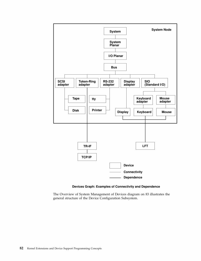
The Overview of System Management of Devices diagram on 83 illustrates thegeneral structure of the Device Configuration Subsystem.
System
Bus
SIO(Standard I/O)
SCSIadapter
Token-Ringadapter
RS-232adapter
Displayadapter
Keyboardadapter
Mouseadapter
TR-IF
Tape
Disk Display Keyboard
LFT
tty
PrinterMouse
Device
Connectivity
Dependence
SystemPlanar
I/O Planar
TCP/IP
System Node
Devices Graph: Examples of Connectivity and Dependence
82 Kernel Extensions and Device Support Programming Concepts
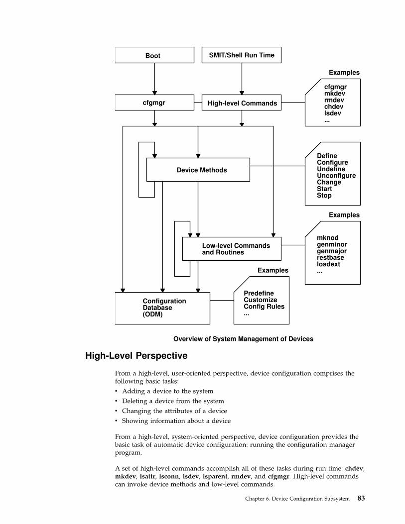
High-Level Perspective
From a high-level, user-oriented perspective, device configuration comprises thefollowing basic tasks:
v Adding a device to the system
v Deleting a device from the system
v Changing the attributes of a device
v Showing information about a device
From a high-level, system-oriented perspective, device configuration provides thebasic task of automatic device configuration: running the configuration managerprogram.
A set of high-level commands accomplish all of these tasks during run time: chdev,mkdev, lsattr, lsconn, lsdev, lsparent, rmdev, and cfgmgr. High-level commandscan invoke device methods and low-level commands.
Boot SMIT/Shell Run Time
High-level Commands
cfgmgrmkdevrmdevchdevlsdev...
DefineConfigureUndefineUnconfigureChangeStartStop
mknodgenminorgenmajorrestbaseloadext...
Device Methods
Low-level Commandsand Routines
ConfigurationDatabase(ODM)
PredefineCustomizeConfig Rules...
cfgmgr
Examples
Examples
Examples
Overview of System Management of Devices
Chapter 6. Device Configuration Subsystem 83

Device Method Level
Beneath the high-level commands (including the cfgmgr Configuration Managerprogram) is a set of functions called device methods. These methods performwell-defined configuration steps, including these five functions:
v Defining a device in the configuration database
v Configuring a device to make it available
v Changing a device to make a change in its characteristics
v Unconfiguring a device to make it unavailable
v Undefining a device from the configuration database
Device methods also provide two optional functions for devices that need them:
v Starting a device to take it from the Stopped state to the Available state
v Stopping a device to take it to the Stopped state
The Device States diagram (see “Understanding Device States” on page 90)illustrates all possible device states and how the various methods affect devicestate changes.
The high-level device commands (including cfgmgr) can use the device methods.These methods insulate high-level configuration programs from kernel-specific,hardware-specific, and device-specific configuration steps. Device methods caninvoke low-level commands.
Low-Level Perspective
Beneath the device methods is a set of low-level device configuration commandsand library routines that can be directly called by device methods as well as byhigh-level configuration programs.
Device Configuration Database Overview
The Configuration database is an object-oriented database. The Object DataManager (ODM) provides facilities for accessing and manipulating it throughobject classes.
There are actually two databases used in the configuration process:
Predefined database Contains information about all possible types of devices thatcan be defined for the system.
Customized database Describes all devices currently defined for use in the system.Items are referred to as device instances.
″ODM Device Configuration Object Classes″ in AIX Technical Reference: Kernel andSubsystems Volume 1 provides access to the object classes that make up thePredefined and Customized databases.
Devices must be defined in the database for the system to make use of them. For adevice to be in the Defined state, the Configuration database must contain acomplete description of it. This information includes items such as the devicedriver name, the device major and minor numbers, the device method names, thedevice attributes, connection information, and location information.
84 Kernel Extensions and Device Support Programming Concepts

Basic Device Configuration Procedures Overview
At system boot time, the Configuration Manager (cfgmgr high-level command) isautomatically invoked to configure all devices detected as well as any devicewhose device information is stored in the Configuration database. At run time, youcan configure a specific device by directly invoking (or indirectly invoking througha usability interface layer) high-level device commands. The″ Overview of SystemManagement of Devices″ diagram on 83 illustrates this interface.
High-level device commands invoke methods and allow the user to add, delete,show, and change devices and their associated attributes.
When a specific device is defined through its Define method, the information fromthe Predefined database for that type of device is used to create the informationdescribing the specific device instance. This specific device instance information isthen stored in the Customized database.
The process of configuring a device is often highly device-specific. The Configuremethod for a kernel device must:
v Load the device’s driver into the kernel.
v Pass the device dependent structure (DDS) describing the device instance to thedriver (see “Device Dependent Structure (DDS) Overview” on page 95).
v Create a special file for the device in the /dev directory.
Of course, many devices do not have device drivers. For this type of device theconfigured state is not as meaningful. However, it still has a Configure methodthat simply marks the device as configured or performs more complex operationsto determine if there are any devices attached to it.
The configuration process requires that a device be defined or configured before adevice attached to it can be defined or configured. At system boot time, theConfiguration Manager first configures the system device as shown in the ″DevicesGraph: Examples of Connectivity and Dependence″ diagram on 82. The remainingdevices are configured by traversing down the parent-child connections layer bylayer. The Configuration Manager then configures any pseudo-devices that need tobe configured.
Device Configuration Manager Overview
The Configuration Manager is a rule-driven program that automatically configuresdevices in the system during system boot and run time. When the ConfigurationManager is invoked, it reads rules from the Configuration Rules object class andperforms the indicated actions.
Devices in the system are organized in clusters of tree structures known as nodes.Each tree is a logical subsystem by itself. For example, the system node consists ofall the physical devices in the system. The top of the node is the system device.Below the bus and connected to it are the adapters. The bottom of the hierarchycontains devices to which no other devices are connected. Most pseudo-devices,including low -function terminal ( HFT LFT ) and pseudo-terminal (pty) devices,are organized as separate tree structures or nodes.
Chapter 6. Device Configuration Subsystem 85
Devices Graph
The Devices Graph: Examples of Connectivity and Dependence diagram on 82provides an example of the connections and dependencies of devices in the system.“Understanding Device Dependencies and Child Devices” on page 93 providesmore information.
Configuration Rules
Each rule in the Configuration Rules (Config_Rules) object class specifies aprogram name that the Configuration Manager must execute. These programs aretypically the configuration programs for the devices at the top of the nodes. Whenthese programs are invoked, the names of the next lower-level devices that need tobe configured are returned.
If the -m (mask) flag is not used, the cfgmgr command executes all of the rules forthe specified phase. When a mask is specified, the cfgmgr command applies themask to each rule for the phase. If the mask specified with the -m flag matches theboot_mask field from the configuration rules, the rule is executed. Otherwise, thecfgmgr command does not execute the rule. In this way, phase 1 of the bootprocess can be tailored for a particular type of boot (for example, DISK_BOOT).
The Configuration Manager configures the next lower-level devices by invokingthe configuration methods for those devices. In turn, those configuration methodsreturn a list of to-be-configured device names. The process is repeated until nomore device names are returned. As a result, all devices in the same node areconfigured in transverse order. There are three different types of rules:
v Phase 1
v Phase 2
v Service
The system boot process is divided into two phases. In each phase, theConfiguration Manager is invoked. During phase 1, the Configuration Manager iscalled with a -f flag, which specifies that phase = 1 rules are to be executed. Thisresults in the configuration of base devices into the system, so that the root filesystem can be used. During phase 2, the Configuration Manager is called with a -sflag, which specifies that phase = 2 rules are to be executed. This results in theconfiguration of the rest of the devices into the system.
″Understanding System Boot Processing″ in AIX Version 4.3 System ManagementGuide: Operating System and Devices contains diagrams that illustrate the separatestep of system boot processing.
The Configuration Manager invokes the programs in the order specified by thesequence value in the rule. In general, the lower the sequence number within agiven phase, the higher the priority. Thus, a rule with a 2 sequence number isexecuted before a rule with a sequence number of 5. An exception is made for 0sequence numbers, which indicate a don’t-care condition. Any rule with a sequencenumber of 0 is executed last. The Configuration Rules (Config_Rules) object classprovides an example of this process.
If device names are returned from the program invoked, the ConfigurationManager finishes traversing the node tree before it invokes the next program. Notethat some program names may not be associated with any devices, but they mustbe included to configure the system.
86 Kernel Extensions and Device Support Programming Concepts
Invoking the Configuration Manager
During system boot time, the Configuration Manager is run in two phases. Inphase 1, it configures the base devices needed to successfully start the system.These devices include the root volume group, which permits the configurationdatabase to be read in from the root file system.
In phase 2, the Configuration Manager configures the remaining devices using theconfiguration database from the root file system. During this phase, different rulesare used, depending on the key switch position on the front panel. If the key is inservice position, the rules for service mode are used. Otherwise, the phase 2 rulesare used.
The Configuration Manager can also be invoked during run time to configure allthe detectable devices that may have been turned off at system boot or added afterthe system boot. In this case, the Configuration Manager uses the phase 2 rules.
Device Classes, Subclasses, and Types Overview
To manage the wide variety of devices it supports more easily, the operatingsystem classifies them hierarchically. One advantage of this arrangement is thatdevice methods and high-level commands can operate against a whole set ofsimilar devices.
Devices are categorized into three main groups:
v Functional classes
v Functional subclasses
v Device types
Devices are organized into a set of functional classes at the highest level. From auser’s point of view, all devices belonging to the same class perform the samefunctions. For example, all printer devices basically perform the same function ofgenerating printed output.
However, devices within a class can have different interfaces. A class can thereforebe partitioned into a set of functional subclasses in which devices belonging to thesame subclass have similar interfaces. For example, serial printers and parallelprinters form two subclasses of printer devices.
Finally, a device subclass is a collection of device types. All devices belonging to thesame device type share the same manufacturer’s model name and number. Forexample, 3812-2 (model 2 Pageprinter) and 4201 (Proprinter II) printers representtwo types of printers.
Devices of the same device type can be managed by different drivers if the typebelongs to more than one subclass. For example, the 4201 printer belongs to boththe serial interface and parallel interface subclasses of the printer class, althoughthere are different drivers for the two interfaces. However, a device of a particularclass, subclass, and type can be managed by only one device driver.
Devices in the system are organized in clusters of tree structures known as nodes.For example, the system node consists of all the physical devices in the system. Atthe top of the node is the system device. Below the bus and connected to it are the
Chapter 6. Device Configuration Subsystem 87

adapters. The bottom of the hierarchy contains the devices to which no otherdevices are connected. Most pseudo-devices, including LFT and PTY, are organizedas separate nodes.
The Devices Graph: Examples of Connectivity and Dependence diagram on 82illustrates this structure.
Writing a Device Method
Device methods are programs associated with a device that perform basic deviceconfiguration operations. These operations consist of defining, undefining,configuring, unconfiguring, and reconfiguring a device. Some devices also useoptional start and stop operations.
There are five basic device methods:
Define Creates a device instance in the Customized database.
Configure Configures a device instance already represented in the Customizeddatabase. This method is responsible for making a device available for usein the system.
Change Reconfigures a device by allowing device characteristics or attributes to bechanged.
Unconfigure Makes a configured device unavailable for use in the system. The deviceinstance remains in the Customized database but must be reconfiguredbefore it can be used.
Undefine Deletes a device instance from the Customized database.
Some devices also require these two optional methods:
Stop Provides the ability to stop a device without actually unconfiguring it. Forexample, a command can be issued to the device driver telling it to stopaccepting normal I/O requests.
Start Starts a device that has been stopped with the Stop method. For example, acommand can be issued to the device driver informing it that it can now acceptnormal I/O requests.
Invoking Methods
One device method can invoke another device method. For instance, a Configuremethod for a device may need to invoke the Define method for child devices. TheChange method can invoke the Unconfigure and Configure methods. To ensureproper operation, a method that invokes another method must always use theodm_run_method subroutine.
Example Methods
See the /usr/samples directory for example device method source code. Thesesource code excerpts are provided for example purposes only. The examples do notfunction as written.
88 Kernel Extensions and Device Support Programming Concepts

Understanding Device Methods Interfaces
Device methods are not executed directly from the command line. They are onlyinvoked by the Configuration Manager at boot time or by the cfgmgr, mkdev,chdev, and rmdev configuration commands at run time. As a result, any devicemethod you write should meet well-defined interfaces.
The parameters that are passed into the methods as well as the exit codes returnedmust both satisfy the requirements for each type of method. Additionally, somemethods must write information to the stdout and stderr files.
These interfaces are defined for each of the device methods in the individualarticles on writing each method.
To better understand how these interfaces work, one needs to understand, at leastsuperficially, the flow of operations through the Configuration Manager and therun-time configuration commands.
Configuration Manager
The Configuration Manager begins by invoking a Node Configuration programlisted in one of the rules in the Configuration Rules (Config_Rules) object class. Anode is a group of devices organized into a tree structure representing the variousinterconnections of the devices. The Node Configuration program is responsible forstarting the configuration process for a node. It does this by querying theCustomized database to see if the device at the top of the node is represented inthe database. If so, the program writes the logical name of the device to the stdoutfile and then returns to the Configuration Manager.
The Configuration Manager intercepts the Node Configuration program’s stdoutfile to obtain the name of the device that was written. It then invokes theConfigure method for that device. The device’s Configure method performs thesteps necessary to make the device available. If the device is not an intermediateone, the Configure method simply returns to the Configuration Manager. However,if the device is an intermediate device that has child devices (see “UnderstandingDevice Dependencies and Child Devices” on page 93), the Configure method mustdetermine whether any of the child devices need to be configured. If so, theConfigure method writes the names of all the child devices to be configured to thestdout file and then returns to the Configuration Manager.
The Configuration Manager intercepts the Configure method’s stdout file toretrieve the names of the children. It then invokes, one at a time, the Configuremethods for each child device. Each of these Configure methods operates asdescribed for the parent device. For example, it might simply exit when complete,or write to its stdout file a list of additional device names to be configured andthen exit. The Configuration Manager will continue to intercept the device nameswritten to the stdout file and to invoke the Configure methods for those devicesuntil the Configure methods for all the devices have been run and no more namesare written to the stdout file.
Chapter 6. Device Configuration Subsystem 89
Run-Time Configuration Commands
User configuration commands invoke device methods during run time.
mkdev The mkdev command is invoked to define or configure, or define andconfigure, devices at run time. If just defining a device, the mkdev commandinvokes the Define method for the device. The Define method creates thecustomized device instance in the Customized Devices (CuDv) object class andwrites the name assigned to the device to the stdout file. The mkdev commandintercepts the device name written to the stdout file by the Define method tolearn the name of the device. If user-specified attributes are supplied with the -aflag, the mkdev command then invokes the Change method for the device.
If defining and configuring a device, the mkdev command invokes the Definemethod, gets the name written to the stdout file with the Define method,invokes the Change method for the device if user-specified attributes weresupplied, and finally invokes the device’s Configure method.
If only configuring a device, the device must already exist in the CuDv objectclass and its name must be specified to the mkdev command. In this case, themkdev command simply invokes the Configure method for the device.
chdev The chdev command is used to change the characteristics, or attributes, of adevice. The device must already exist in the CuDv object class, and the name ofthe device must be supplied to the chdev command. The chdev commandsimply invokes the Change method for the device.
rmdev The rmdev command can be used to undefine or unconfigure, or unconfigureand undefine, a device. In all cases, the device must already exist in the CuDvobject class and the name of the device must be supplied to the rmdevcommand. The rmdev command then invokes the Undefine method, theUnconfigure method, or the Unconfigure method followed by the Undefinemethod, depending on the function requested by the user.
cfgmgr The cfgmgr command can be used to configure all detectable devices that didnot get configured at boot time. This might occur if the devices had beenpowered off at boot time. The cfgmgr command is the Configuration Managerand operates in the same way at run time as it does at boot time. The boot timeoperation is described in “Device Configuration Manager Overview” on page 85.
Understanding Device States
Device methods are responsible for changing the state of a device in the system. Adevice can be in one of four states as represented by the Device Status Flagdescriptor in the device’s object in the Customized Devices (CuDv) object class.
The Device States diagram on 91 illustrates both the possible states and the devicemethods that affect them.
90 Kernel Extensions and Device Support Programming Concepts

Defined Represented in the Customized database, but neither configured noravailable for use in the system.
Available Configured and available for use.
Undefined Not represented in the Customized database.
Stopped Configured, but not available for use by applications. (Optional state)
The Define method is responsible for creating a device instance in the Customizeddatabase and setting the state to Defined. The Configure method performs alloperations necessary to make the device usable and then sets the state to Available.
The Change method usually does not change the state of the device. If the deviceis in the Defined state, the Change method applies all changes to the database andleaves the device defined. If the device is in the Available state, the Changemethod attempts to apply the changes to both the database and the actual device,while leaving the device available. However, if an error occurs when applying thechanges to the actual device, the Change method may need to unconfigure thedevice, thus changing the state to Defined.
Any Unconfigure method you write must perform the operations necessary tomake a device unusable. Basically, this method undoes the operations performedby the Configure method and sets the device state to Defined. Finally, the Undefinemethod actually deletes all information for a device instance from the Customizeddatabase, thus reverting the instance to the Undefined state.
The Stopped state is an optional state that some devices require. A device thatsupports this state needs Start and Stop methods. The Stop method changes thestate from Available to Stopped. The Start method changes it from Stopped back toAvailable.
DefineMethod
UndefineMethod
ConfigureMethod
UnconfigureMethod
StartMethod
StopMethod
ConfigureMethod
UnconfigureMethod
Undefined
Defined
Stopped
Available
Device States
Chapter 6. Device Configuration Subsystem 91

Adding an Unsupported Device to the System
The operating system provides support for a wide variety of devices. However,some devices are not currently supported. You can add a currently unsupporteddevice only if you also add the necessary software to support it.
To add a currently unsupported device to your system, you may need to:
v Modify the Predefined database (see “Modifying the Predefined Database”)
v Add appropriate device methods (see “Adding Device Methods”)
v Add a device driver (see “Adding a Device Driver” on page 93)
v Use procedures (see “Using installp Procedures” on page 93)
Modifying the Predefined Database
To add a currently unsupported device to your system, you must modify thePredefined database. To do this, you must add information about your device tothree predefined object classes:
v Predefined Devices (PdDv) object class
v Predefined Attribute (PdAt) object class
v Predefined Connection (PdCn) object class
To describe the device, you must add one object to the PdDv object class toindicate the class, subclass, and device type (see “Device Classes, Subclasses, andTypes Overview” on page 87). You must also add one object to the PdAt objectclass for each device attribute, such as interrupt level or block size. Finally, youmust add objects to the PdCn object class if the device is an intermediate device. Ifthe device is an intermediate device, you must add an object for each differentconnection location on the intermediate device.
You can use the odmadd Object Data Manager (ODM) command from thecommand line or in a shell script to populate the necessary Predefined objectclasses from stanza files.
The Predefined database is shipped populated with supported devices. For somesupported devices, such as serial and parallel printers and SCSI disks, the databasealso contains generic device objects. These generic device objects can be used toconfigure other similar devices that are not explicitly supported in the Predefineddatabase.
For example, if you have a serial printer that closely resembles a printer supportedby the system, and the system’s device driver for serial printers works on yourprinter, you can add the device driver as a printer of type osp (other serialprinter). If these generic devices successfully add your device, you do not need toprovide additional system software.
Adding Device Methods
You must add device methods when adding system support for a new device.Primary methods needed to support a device are:
v Define
v Configure
92 Kernel Extensions and Device Support Programming Concepts

v Change
v Undefine
v Unconfigure
When adding a device that closely resembles devices already supported, you mightbe able to use one of the methods of the already supported device. For example, ifyou are adding a new type of SCSI disk whose interfaces are identical tosupported SCSI disks, the existing methods for SCSI disks may work. If so, all youneed to do is populate the Predefined database with information describing thenew SCSI disk, which will be similar to information describing a supported SCSIdisk.
If you need instructions on how to write a device method, see “Writing a DeviceMethod” on page 88.
Adding a Device Driver
If you add a new device, you will probably need to add a device driver. However,if you are adding a new device that closely resembles an already supported device,you might be able to use the existing device driver. For example, when you areadding a new type of SCSI disk whose interfaces are identical to supported SCSIdisks, the existing SCSI disk device driver may work.
Using installp ProceduresThe installp procedures provide a method for adding the software and Predefinedinformation needed to support your new device. You may need to write shellscripts to perform tasks such as populating the Predefined database.
Understanding Device Dependencies and Child Devices
The dependencies that one device has on another can be represented in theconfiguration database in two ways. One way usually represents physicalconnections such as a keyboard device connected to a particular keyboard adapter.The keyboard device has a dependency on the keyboard adapter in that it cannotbe configured until after the adapter is configured. This relationship is usuallyreferred to as a parent-child relationship, with the adapter as parent and thekeyboard device as child. These relationships are represented with the ParentDevice Logical Name and Location Where Device Is Connected descriptors in theCustomized Devices (CuDv) object class.
The second method represents a logical connection. A device method can add anobject identifying both a dependent device and the device upon which it dependsto the Customized Dependency (CuDep) object class (see “Writing a DeviceMethod” on page 88). The dependent device is considered to have a dependency,and the depended-upon device is considered to be a dependency. CuDep objectsare usually added to the database to represent a situation in which one devicerequires access to another device. For example, the hft0 lft0 device depends upon aparticular keyboard or display device.
These two types of dependencies differ significantly. The configuration processuses parent-child dependencies at boot time to configure all devices that make upa node. The CuDep dependency is usually only used by a device’s Configuremethod to retrieve the names of the devices on which it depends. The Configuremethod can then check to see if those devices exist.
Chapter 6. Device Configuration Subsystem 93

For device methods, the parent-child relationship is the more important.Parent-child relationships affect device-method activities in these ways:
v A parent device cannot be unconfigured if it has a configured child.
v A parent device cannot be undefined if it has a defined or configured child.
v A child device cannot be defined if the parent is not defined or configured.
v A child device cannot be configured if the parent is not configured.
v A parent device’s configuration cannot be changed if it has a configured child.This guarantees that the information about the parent that the child’s devicedriver may be using remains valid.
However, when a device is listed as a dependency of another device in the CuDepobject class, the only effect is to prevent the depended-upon device from beingundefined. The name of the dependency is important to the dependent device. Ifthe depended-upon device were allowed to be undefined, a third device could bedefined and assigned the same name.
Writers of Unconfigure and Change methods for a depended-upon device shouldnot worry about whether the device is listed as a dependency. If thedepended-upon device is actually open by the other device, the Unconfigure andChange operations will fail because their device is busy. But if the depended-upondevice is not currently open, the Unconfigure or Change operations can beperformed without affecting the dependent device.
The possible parent-child connections are defined in the Predefined Connection(PdCn) object class. Each predefined device type that can be a parent device isrepresented in this object class. There is an object for each connection location(such as slots or ports) describing the subclass of devices that can be connected atthat location. The subclass is used to identify each device since it indicates thedevices’ connection type (for example, SCSI or rs232).
There is no corresponding predefined object class describing the possible CuDepdependencies. A device method can be written so that it already knows what thedependencies are. If predefined data is required, it can be added as predefinedattributes for the dependent device in the Predefined Attribute (PdAt) object class.
The ″Devices Graph″ diagram on 82 provides an example of device dependenciesand connections in the system.
Accessing Device Attributes
The predefined device attributes for each type of predefined device are stored inthe Predefined Attribute (PdAt) object class. The objects in the PdAt object classidentify the default values as well as other possible values for each attribute. TheCustomized Attribute (CuAt) object class contains only attributes for customizeddevice instances that have been changed from their default values.
When a customized device instance is created by a Define method, its attributesassume the default values. As a result, no objects are added to the CuAt objectclass for the device. If an attribute for the device is changed from the default valueby the Change method, an object to describe the attribute’s current value is addedto the CuAt object class for the attribute. If the attribute is subsequently changedback to the default value, the Change method deletes the CuAt object for theattribute.
94 Kernel Extensions and Device Support Programming Concepts
Any device methods that need the current attribute values for a device must accessboth the PdAt and CuAt object classes. If an attribute appears in the CuAt objectclass, then the associated object identifies the current value. Otherwise, the defaultvalue from the PdAt attribute object identifies the current value.
Modifying an Attribute Value
When modifying an attribute value, methods you write must obtain the objects forthat attribute from both the PdAt and CuAt object classes.
Any method you write must be able to handle the following four scenarios:
v If the new value differs from the default value and no object currently exists inthe CuAt object class, any method you write must add an object into the CuAtobject class to identify the new value.
v If the new value differs from the default value and an object already exists inthe CuAt object class, any method you write must update the CuAt object withthe new value.
v If the new value is the same as the default value and an object exists in theCuAt object class, any method you write must delete the CuAt object for theattribute.
v If the new value is the same as the default value and no object exists in theCuAt object class, any method you write does not need to do anything.
Your methods can use the getattr and putattr subroutines to get and modifyattributes. The getattr subroutine checks both the PdAt and CuAt object classesbefore returning an attribute to you. It always returns the information in the formof a CuAt object even if returning the default value from the PdAt object class.
Use the putattr subroutine to modify these attributes.
Device Dependent Structure (DDS) Overview
A device dependent structure (DDS) contains information that describes a deviceinstance to the device driver. It typically contains information aboutdevice-dependent attributes as well as other information the driver needs tocommunicate with the device. In many cases, information about a device’s parentis included. (For instance, a driver needs information about the adapter and thebus the adapter is plugged into to communicate with a device connected to anadapter.)
A device’s DDS is built each time the device is configured. The Configure methodcan fill in the DDS with fixed values, computed values, and information from theConfiguration database. Most of the information from the Configuration databaseusually comes from the attributes for the device in the Customized Attribute(CuAt) object class, but can come from any of the object classes. Information fromthe database for the device’s parent device or parent’s parent device can also beincluded. The DDS is passed to the device driver with the SYS_CFGDD flag of thesysconfig subroutine, which calls the device driver’s ddconfig subroutine with theCFG_INIT command.
Chapter 6. Device Configuration Subsystem 95

How the Change Method Updates the DDS
The Change method is invoked when changing the configuration of a device. TheChange method must ensure consistency between the Configuration database andthe view that any device driver may have of the device. This is accomplished by:
1. Not allowing the configuration to be changed if the device has configuredchildren; that is, children in either the Available or Stopped states. This ensuresthat a DDS built using information in the database about a parent deviceremains valid because the parent cannot be changed.
2. If a device has a device driver and the device is in either the Available orStopped state, the Change method must communicate to the device driver anychanges that would affect the DDS. This may be accomplished with ioctloperations, if the device driver provides the support to do so. It can also beaccomplished by taking the following steps:
a. Terminating the device instance by calling the sysconfig subroutine with theSYS_CFGDD operation. This operation calls the device driver’s ddconfigsubroutine with the CFG_TERM command.
b. Rebuilding the DDS using the changed information.
c. Passing the new DDS to the device driver by calling the sysconfigsubroutine SYS_CFGDD operation. This operation then calls the ddconfigsubroutine with the CFG_INIT command.
Many Change methods simply invoke the device’s Unconfigure method, applychanges to the database, and then invoke the device’s Configure method. Thisprocess ensures the two stipulated conditions since the Unconfigure method, andthus the change, will fail, if the device has Available or Stopped children. Also, ifthe device has a device driver, its Unconfigure method terminates the deviceinstance. Its Configure method also rebuilds the DDS and passes it to the driver.
Guidelines for DDS Structure
There is no single defined DDS format. Writers of device drivers and devicemethods must agree upon a particular device’s DDS format. When obtaininginformation about a parent device, you may want to group that informationtogether in the DDS.
When building a DDS for a device connected to an adapter card, you will typicallyneed the following adapter information:
slot number Obtained from the connwhere descriptor of the adapter’s CustomizedDevice (CuDv) object.
bus resources Obtained from attributes for the adapter in the Customized Attribute(CuAt) or Predefined Attribute (PdAt) object classes. These includeattributes for bus interrupt levels, interrupt priorities, bus memoryaddresses, bus I/O addresses, and DMA arbitration levels.
These two attributes must be obtained for the adapter’s parent bus device:
bus_id Identifies the I/O bus. This field is needed by the device driver to access theI/O bus.
bus_type Identifies the type of bus such as a Micro Channel bus or a PC AT bus.
96 Kernel Extensions and Device Support Programming Concepts

Note: The getattr device configuration subroutine should be used wheneverattributes are obtained from the Configuration database. This subroutinereturns the Customized attribute value if the attribute is represented in theCustomized Attribute object class. Otherwise, it returns the default valuefrom the Predefined Attribute object class.
Finally, a DDS generally includes the device’s logical name. This is used by thedevice driver to identify the device when logging an error for the device.
Example of DDSThe following example provides a guide for using DDS format.
/* Device DDS */struct device_dds {
/* Bus information */ulong bus_id; /* I/O bus id */ushort us_type; /* Bus type, i.e. BUS_MICRO_CHANNEL*//* Adapter information */int slot_num; /* Slot number */ulong io_addr_base; /* Base bus i/o address */int bus_intr_lvl; /* bus interrupt level */int intr_priority; /* System interrupt priority */int dma_lvl; /* DMA arbitration level *//* Device specific information */int block_size; /* Size of block in bytes */int abc_attr; /* The abc attribute */int xyz_attr; /* The xyz attribute */char resource_name[16]; /* Device logical name */
};
List of Device Configuration Commands
The high-level device configuration commands are:
chdev Changes a device’s characteristics.
lsdev Displays devices in the system and their characteristics.
mkdev Adds a device to the system.
rmdev Removes a device from the system.
lsattr Displays attribute characteristics and possible values of attributes for devicesin the system.
lsconn Displays the connections a given device, or kind of device, can accept.
lsparent Displays the possible parent devices that accept a specified connection type ordevice.
cfgmgr Configures devices by running the programs specified in the ConfigurationRules (Config_Rules) object class.
The low-level device configuration commands are:
bootlist Alters the list of boot devices seen by ROS when the machine boots.
restbase Reads the base customized information from the boot image and restores itinto the Device Configuration database used during system boot phase 1.
savebase Saves information about base customized devices in the Device ConfigurationDatabase onto the boot device.
Associated commands are:
devnm Names a device.
Chapter 6. Device Configuration Subsystem 97

mknod Creates a special file (directory entry and i-node).
lscfg Displays diagnostic information about a device.
List of Device Configuration Subroutines
Following are the preexisting conditions for using the device configuration librarysubroutines:
v The caller has initialized the Object Data Manager (ODM) before invoking any ofthese library subroutines. This is done using the initialize_odm subroutine.Similarly, the caller must terminate the ODM (using the terminate_odmsubroutine) after these library subroutines have completed. Only the attrvalsubroutine does not require initialization and termination.
v Since all of these library subroutines (except the attrval, getattr, and putattrsubroutines) access the Customized Device Driver (CuDvDr) object class, thisclass must be exclusively locked and unlocked at the proper times. Theapplication does this by using the odm_lock and odm_unlock subroutines. Inaddition, those library subroutines that access the CuDvDr object classexclusively lock this class with their own internal locks.
Following are the device configuration library subroutines:
attrval Verifies that attributes are within range.
busresolve Allocates bus resources for Micro channel adapters.
genmajor Generates the next available major number for a device.
genminor Generates the smallest unused minor number or a requested minor numberfor a device.
genseq Generates a sequence number.
getattr Returns attribute objects from either the Predefined Attribute (PdAt) orCustomized Attribute (CuAt) object class, or both.
getminor Gets from the CuDvDr object class the minor numbers for a given majornumber.
loadext Loads or unloads and binds or unbinds device drivers to or from thekernel.
putattr Updates attribute information in the CuAt object class or creates a newobject for the attribute information.
reldevno Releases the minor number or major number, or both, for a device instance.
relmajor Releases the major number associated with a specific device driver instance.
98 Kernel Extensions and Device Support Programming Concepts

Chapter 7. Communications I/O Subsystem
The Communication I/O Subsystem design introduces a more efficient, streamlinedapproach to attaching data link control (DLC) processes to communication andLAN adapters.
The Communication I/O Subsystem consists of one or more physical devicehandlers (PDHs) that control various communication adapters. The interface to thephysical device handlers can support any number of processes, the limit beingdevice-dependent.
Note: A PDH, as used for the Communications I/O, provides both the devicehead role for interfacing to users, and the device handler role for performingI/O to the device.
A communications PDH is a special type of multiplexed character device driver(see “Communications Physical Device Handler Model Overview” on page 100).Information common to all communications device handlers is discussed here.Additionally, individual communications PDHs have their own adapter-specificsets of information. Refer to the following to learn more about the adapter types:
v “MPQP Device Handler Interface Overview” on page 104
v “Serial Optical Link Device Handler Overview” on page 108
Each adapter type requires a device driver. Each PDH can support one or moreadapters of the same type.
There are two interfaces a user can use to access a PDH. One is from a user-modeprocess (application space), and the other is from a kernel-mode process (withinthe kernel).
User-Mode Interface to a Communications PDH
The user-mode process uses system calls (open, close, select, poll, ioctl, read,write) to interface to the PDH to send or receive data. The poll or selectsubroutine notifies a user-mode process of available receive data, availabletransmit, and status and exception conditions.
Kernel-Mode Interface to a Communications PDH
The kernel-mode interface to a communications PDH differs from the interfacesupported for a user-mode process in the following ways:
v Kernel services are used instead of system calls. This means that, for example,the fp_open kernel service is used instead of the open subroutine. The sameholds true for the fp_close, fp_ioctl, and fp_write kernel services.
v The ddread entry point, ddselect entry point, and CIO_GET_STAT (Get Status)ddioctl operation are not supported in kernel mode. Instead, kernel-modeprocesses specify at open time the addresses of their own procedures forhandling receive data available, transmit available and status or exceptionconditions. The PDH directly calls the appropriate procedure, whenever that
© Copyright IBM Corp. 1997, 1999 99

condition arises. These kernel procedures must execute and return quickly sincethey are executing within the priority of the PDH.
v The ddwrite operation for a kernel-mode process differs from a user-modeprocess in that there are two ways to issue a ddwrite operation to transmit data:
– Transmit each buffer of data with the fp_write kernel service.
– Use the fast write operation, which allows the user to directly call theddwrite operation (no context switching) for each buffer of data to betransmitted. This operation helps increase the performance of transmitteddata. A fp_ioctl (CIO_GET_FASTWRT) kernel service call obtains thefunctional address of the write function. This address is used on allsubsequent write function calls. Support of the fast write operation is optionalfor each device.
CDLI Device Drivers
Some device drivers have a different design and use the services known asCommon Data Link Interface (CDLI). The following are device drivers that useCDLI:
v Forum-Compliant ATM LAN Emulation Device Driver
v Fiber Distributed Data Interface (FDDI) Device Driver
v High-Performance (8fc8) Token-Ring Device Driver
v High-Performance (8fa2) Token-Ring Device Driver
v Ethernet Device Drivers
Communications Physical Device Handler Model Overview
A physical device handler (PDH) must provide eight common entry points. Anindividual PDH names its entry points by placing a unique identifier in front ofthe supported command type.The following are the required eight communicationsPDH entry points:
ddconfig Performs configuration functions for a device handler. Supported the sameway that the common ddconfig entry point is.
ddmpx Allocates or deallocates a channel for a multiplexed device handler. Supportedthe same way as the common ddmpx device handler entry point.
ddopen Performs data structure allocation and initialization for a communicationsPDH. Supported the same way as the common ddopen entry point.Time-consuming tasks, such as port initialization and connectionestablishment, are deferred until the (CIO_START) ddioctl call is issued. APDH can support multiple users of a single port.
ddclose Frees up system resources used by the specified communications device untilthey are needed again. Supported the same way as the common ddclose entrypoint.
ddwrite Queues a message for transmission or blocks until the message can be queued.The ddwrite entry point can attempt to queue a transmit request(nonblocking) or wait for it to be queued (blocking), depending on the settingof the DNDELAY flag. The caller has the additional option of requesting anasynchronous acknowledgment when the transmission actually completes.
ddread Returns a message of data to a user-mode process. Supports blocking ornonblocking reads depending on the setting of the DNDELAY flag. A blockingread request does not return to the caller until data is available. A nonblockingread returns with a message of data if it is immediately available. Otherwise, itreturns a length of 0 (zero).
100 Kernel Extensions and Device Support Programming Concepts
ddselect Checks to see if a specified event or events has occurred on the device for auser-mode process. Supported the same way as the common ddselect entrypoint.
ddioctl Performs the special I/O operations requested in an ioctl subroutine.Supported the same way as the common ddioctl entry point. In addition, acommunications PDH must support the following four options:
v CIO_START
v CIO_HALT
v CIO_QUERY
v CIO_GET_STAT
Individual PDHs can add additional commands. Hardware initialization and othertime-consuming activities, such as call establishment, are performed during theCIO_START operation.
Use of mbuf Structures in the Communications PDH
PDHs use mbuf structures to buffer send and receive data. These structures allowthe PDH to gather data when transmitting frames and scatter for receiveoperations. The mbuf structures are internal to the kernel and are used only bykernel-mode processes and PDHs.
PDHs and kernel-mode processes require a set of utilities for obtaining andreturning mbuf structures from a buffer pool.
Kernel-mode processes use the Berkeley mbuf scheme for transmit and receivebuffers. The structure for an mbuf is defined in the /usr/include/sys/mbuf.h file.
Common Communications Status and Exception Codes
In general, communication device handlers return codes from a group of commonexception codes. However, device handlers for specific communication devices canreturn device-specific exception codes. Common exception codes are defined in the/usr/include/sys/comio.h file and include the following:
CIO_OK Indicates that the operation was successful.
CIO_BUF_OVFLW Indicates that the data was lost due to buffer overflow.
CIO_HARD_FAIL Indicates that a hardware failure was detected.
CIO_NOMBUF Indicates that the operation was unable to allocate mbufstructures.
CIO_TIMEOUT Indicates that a time-out error occurred.
CIO_TX_FULL Indicates that the transmit queue is full.
CIO_NET_RCVRY_ENTER Enters network recovery.
CIO_NET_RCVRY_EXIT Indicates the device handler is exiting network recovery.
CIO_NET_RCVRY_MODE Indicates the device handler is in Recovery mode.
CIO_INV_CMD Indicates that an invalid command was issued.
CIO_BAD_MICROCODE Indicates that the microcode download failed.
CIO_NOT_DIAG_MODE Indicates that the command could not be accepted becausethe adapter is not open in Diagnostic mode.
CIO_BAD_RANGE Indicates that the parameter values have failed a range check.
CIO_NOT_STARTED Indicates that the command could not be accepted becausethe device has not yet been started by the first call toCIO_START operation.
CIO_LOST_DATA Indicates that the receive packet was lost.
Chapter 7. Communications I/O Subsystem 101

CIO_LOST_STATUS Indicates that a status block was lost.
CIO_NETID_INV Indicates that the network ID was not valid.
CIO_NETID_DUP Indicates that the network ID was a duplicate of an existingID already in use on the network.
CIO_NETID_FULL Indicates that the network ID table is full.
Status Blocks for Communications Device Handlers Overview
Status blocks are used to communicate status and exception information.
User-mode processes receive a status block whenever they request aCIO_GET_STAT operation. A user-mode process can wait for the next availablestatus block by issuing a ddselect entry point with the specified POLLPRI event.
A kernel-mode process receives a status block through the stat_fn procedure. Thisprocedure is specified when the device is opened with the ddopen entry point.
Status blocks contain a code field and possible options. The code field indicates thetype of status block code (for example, CIO_START_DONE). A status block’soptions depend on the block code. The C structure of a status block is defined inthe /usr/include/sys/comio.h file.
The following are the six common status codes:
v CIO_START_DONE (see “CIO_START_DONE”)
v CIO_HALT_DONE (see “CIO_HALT_DONE”)
v CIO_TX_DONE (see “CIO_TX_DONE” on page 103)
v CIO_NULL_BLK (see “CIO_NULL_BLK” on page 103)
v CIO_LOST_STATUS (see “CIO_LOST_STATUS” on page 103)
v CIO_ASYNC_STATUS (see “CIO_ASYNC_STATUS” on page 103)
Additional device-dependent status block codes may be defined.
CIO_START_DONE
This block is provided by the device handler when the CIO_START operationcompletes:
option[0] The CIO_OK or CIO_HARD_FAIL status/exception code from the commonor device-dependent list. See 101 or 101.
option[1] The low-order two bytes are filled in with the netid field. This field ispassed when the CIO_START operation is invoked.
option[2] Device-dependent.
option[3] Device-dependent.
CIO_HALT_DONE
This block is provided by the device handler when the CIO_HALT operationcompletes:
option[0] The CIO_OK status/exception code from the common or device-dependentlist (see 101).
102 Kernel Extensions and Device Support Programming Concepts

option[1] The low-order two bytes are filled in with the netid field. This field ispassed when the CIO_START operation is invoked.
option[2] Device-dependent.
option[3] Device-dependent.
CIO_TX_DONE
The following block is provided when the physical device handler (PDH) isfinished with a transmit request for which acknowledgment was requested:
option[0] The CIO_OK or CIO_TIMEOUT status/exception code from the common ordevice-dependent list. See 101 or 101.
option[1] The write_id field specified in the write_extension structure passed in theext parameter to the ddwrite entry point.
option[2] For a kernel-mode process, indicates the mbuf pointer for the transmittedframe.
option[3] Device-dependent.
CIO_NULL_BLK
This block is returned whenever a status block is requested but there are noneavailable:
option[0] Not used
option[1] Not used
option[2] Not used
option[3] Not used
CIO_LOST_STATUS
This block is returned once after one or more status blocks is lost due to statusqueue overflow. The CIO_LOST_STATUS block provides the following:
option[0] Not used
option[1] Not used
option[2] Not used
option[3] Not used
CIO_ASYNC_STATUS
This status block is used to return status and exception codes that occurunexpectedly:
option[0] The CIO_HARD_FAIL or CIO_LOST_DATA status/exception code from thecommon or device-dependent list. See 101 or 101.
option[1] Device-dependent
option[2] Device-dependent
option[3] Device-dependent
Chapter 7. Communications I/O Subsystem 103

MPQP Device Handler Interface Overview
The Multiprotocol Quad Port (MPQP) device handler is a component of thecommunication I/O subsystem (see “Chapter 7. Communications I/O Subsystem”on page 99). The MPQP device handler interface is made up of the following eightentry points:
mpclose Resets the MPQP device to a known state and returns system resources backto the system on the last close for that adapter. The port no longer transmits orreceives data.
mpconfig Provides functions for initializing and terminating the MPQP device handlerand adapter.
mpioctl Provides the following functions for controlling the MPQP device:
CIO_ST ARTInitiates a session with the MPQP device handler.
CIO_HALTEnds a session with the MPQP device handler.
CIO_QU ERYReads the counter values accumulated by the MPQP device handler.
CIO_GET_STATUSGets the status of the current MPQP adapter and device handler.
MP_START_ARPuts the MPQP port into Autoresponse mode.
MP_STOP_ARPermits the MPQP port to exit Autoresponse mode.
MP_CHG_PARMSPermits the data link control (DLC) to change certain profileparameters after the MPQP device has been started.
mpopen Opens a channel on the MPQP device for transmitting and receiving data.
mpmpx Provides allocation and deallocation of a channel.
mpread Provides the means for receiving data to the MPQP device.
mpselect Provides the means for determining which specified events have occurred onthe MPQP device.
mpwrite Provides the means for transmitting data to the MPQP device.
Binary Synchronous Communication (BSC) with the MPQPAdapter
The MPQP adapter software performs low-level BSC frame-type determination tofacilitate character parsing at the kernel-mode process level. Frames receivedwithout errors are parsed. A message type is returned in the status field of theextension block along with a pointer to the receive buffer. The message typeindicates the type of frame that was received.
For control frames that only contain control characters, the message type isreturned and no data is transferred from the board. For example, if an ACK0 wasreceived, the message type MP_ACK0 is returned in the status field of the extensionblock. In addition, a NULL pointer for the receive buffer is returned. If an erroroccurs, the error status is logged by the device driver. Unlogged buffer overrunerrors are an exception.
104 Kernel Extensions and Device Support Programming Concepts
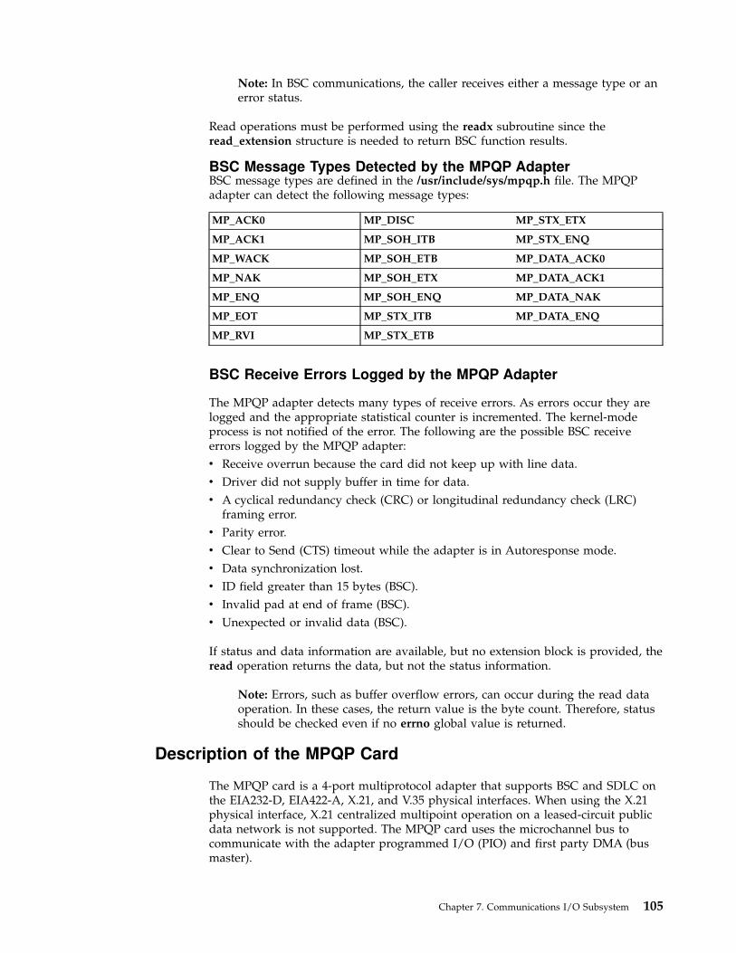
Note: In BSC communications, the caller receives either a message type or anerror status.
Read operations must be performed using the readx subroutine since theread_extension structure is needed to return BSC function results.
BSC Message Types Detected by the MPQP AdapterBSC message types are defined in the /usr/include/sys/mpqp.h file. The MPQPadapter can detect the following message types:
MP_ACK0 MP_DISC MP_STX_ETX
MP_ACK1 MP_SOH_ITB MP_STX_ENQ
MP_WACK MP_SOH_ETB MP_DATA_ACK0
MP_NAK MP_SOH_ETX MP_DATA_ACK1
MP_ENQ MP_SOH_ENQ MP_DATA_NAK
MP_EOT MP_STX_ITB MP_DATA_ENQ
MP_RVI MP_STX_ETB
BSC Receive Errors Logged by the MPQP Adapter
The MPQP adapter detects many types of receive errors. As errors occur they arelogged and the appropriate statistical counter is incremented. The kernel-modeprocess is not notified of the error. The following are the possible BSC receiveerrors logged by the MPQP adapter:
v Receive overrun because the card did not keep up with line data.
v Driver did not supply buffer in time for data.
v A cyclical redundancy check (CRC) or longitudinal redundancy check (LRC)framing error.
v Parity error.
v Clear to Send (CTS) timeout while the adapter is in Autoresponse mode.
v Data synchronization lost.
v ID field greater than 15 bytes (BSC).
v Invalid pad at end of frame (BSC).
v Unexpected or invalid data (BSC).
If status and data information are available, but no extension block is provided, theread operation returns the data, but not the status information.
Note: Errors, such as buffer overflow errors, can occur during the read dataoperation. In these cases, the return value is the byte count. Therefore, statusshould be checked even if no errno global value is returned.
Description of the MPQP Card
The MPQP card is a 4-port multiprotocol adapter that supports BSC and SDLC onthe EIA232-D, EIA422-A, X.21, and V.35 physical interfaces. When using the X.21physical interface, X.21 centralized multipoint operation on a leased-circuit publicdata network is not supported. The MPQP card uses the microchannel bus tocommunicate with the adapter programmed I/O (PIO) and first party DMA (busmaster).
Chapter 7. Communications I/O Subsystem 105

The adapter has 512K bytes of RAM and an Intel 80C186 processor. There are 16dedicated DMA channels between the RAM and the physical ports. The driversand receivers for each of the electrical interfaces reside on a daughter board that isjoined to the base card with two 60-pin connectors.
A shielded cable attaches to the 78-pin D-shell connector on the daughter boardand routes all signals to a fan-out box (FOB). The FOB has nine standardconnectors that support each possible configuration on each port. Standard 15-pinor 25-pin cables are used between the FOB and the modem for each electricalinterface.
The following are the interfaces available on each port:
Port Configurations
Number Port-0 Port-1 Port-2 Port-3
1 EIA-232D EIA-232D EIA-232D EIA-232D
2 EIA-422A EIA-232D EIA-232D EIA-232D
3 V.35 EIA-232D EIA-232D V.35 EIA-232DEIA-232D
EIA-232DEIA-232D
4 X.21 EIA-232D EIA-232D EIA-232D
5 EIA-422A V.35 EIA-232D EIA-232D
6 V.35 V.35 EIA-232D EIA-232D
7 X.21 V.35 EIA-232D EIA-232D
8 EIA-232D EIA-232D EIA-422A EIA-232D
9 EIA-422A EIA-232D EIA-422A EIA-232D
10 V.35 EIA-232D EIA-232D V.35 EIA-422AEIA-422A
EIA-232DEIA-232D
11 X.21 EIA-232D EIA-422A EIA-232D
12 EIA-422A V.35 EIA-422A EIA-232D
13 V.35 V.35 EIA-422A EIA-232D
14 X.21 V.35 EIA-422A EIA-232D
Port 0 EIA232-D, EIA422-A, X.21, and V.35. This port has the highest DMA priority. TheEIA-422A interface on this port has data and clock signals.
Port 1 EIA232-D and V.35.
Port 2 EIA232-D and EIA422-A (data only). The EIA-422A interface on Port 2 only hasdata signals.
Port 3 EIA232-D. This port has the lowest priority.
106 Kernel Extensions and Device Support Programming Concepts

The modem interfaces are supported by each physical interface shown in thefollowing diagram.
Basecardconnection
Connection 1
Connection 3
Connection 2
Connection 4
Connection 5
Connection 6
Connection 7
Connection 8
Connection 0
25-pinD-shell
15-pinD-shell
25-pinD-shell
15-pinD-shell
25-pinD-shell
15-pinD-shell
25-pinD-shell
25-pinD-shell
25-pinD-shell
Port 0: EIA-232DDrivers/receivers/buffers
Port 0: EIA-422A/X21Drivers/receiversX.21 bit patternrecognition logic3 PALSSurge protection
Port 0: V.35Drivers/receivers/buffers
Port 1: EIA-232DDrivers/receivers/buffers
Port 2: EIA-232DDrivers/receivers/buffers
Port 2: EIA-422ADrivers/receivers (data only)Surge protection
Port 3: EIA-232DDrivers/receivers
Port 1: V.35Drivers/receivers/buffers
4-port EIB Fan-outbox/cable
Block Diagram
Chapter 7. Communications I/O Subsystem 107
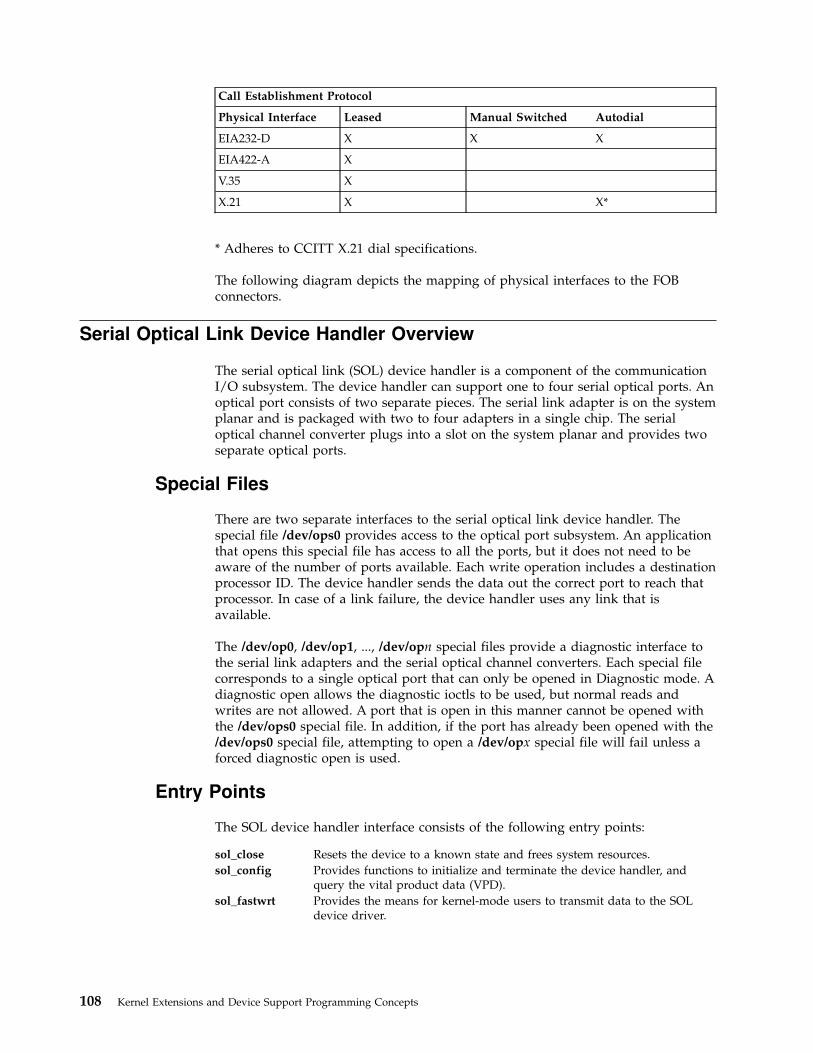
Call Establishment Protocol
Physical Interface Leased Manual Switched Autodial
EIA232-D X X X
EIA422-A X
V.35 X
X.21 X X*
* Adheres to CCITT X.21 dial specifications.
The following diagram depicts the mapping of physical interfaces to the FOBconnectors.
Serial Optical Link Device Handler Overview
The serial optical link (SOL) device handler is a component of the communicationI/O subsystem. The device handler can support one to four serial optical ports. Anoptical port consists of two separate pieces. The serial link adapter is on the systemplanar and is packaged with two to four adapters in a single chip. The serialoptical channel converter plugs into a slot on the system planar and provides twoseparate optical ports.
Special Files
There are two separate interfaces to the serial optical link device handler. Thespecial file /dev/ops0 provides access to the optical port subsystem. An applicationthat opens this special file has access to all the ports, but it does not need to beaware of the number of ports available. Each write operation includes a destinationprocessor ID. The device handler sends the data out the correct port to reach thatprocessor. In case of a link failure, the device handler uses any link that isavailable.
The /dev/op0, /dev/op1, ..., /dev/opn special files provide a diagnostic interface tothe serial link adapters and the serial optical channel converters. Each special filecorresponds to a single optical port that can only be opened in Diagnostic mode. Adiagnostic open allows the diagnostic ioctls to be used, but normal reads andwrites are not allowed. A port that is open in this manner cannot be opened withthe /dev/ops0 special file. In addition, if the port has already been opened with the/dev/ops0 special file, attempting to open a /dev/opx special file will fail unless aforced diagnostic open is used.
Entry Points
The SOL device handler interface consists of the following entry points:
sol_close Resets the device to a known state and frees system resources.
sol_config Provides functions to initialize and terminate the device handler, andquery the vital product data (VPD).
sol_fastwrt Provides the means for kernel-mode users to transmit data to the SOLdevice driver.
108 Kernel Extensions and Device Support Programming Concepts
sol_ioctl Provides various functions for controlling the device. The valid sol_ioctloperations are:
CIO_GET_FASTWRTGets attributes needed for the sol_fastwrt entry point.
CIO_GET_STATGets the device status.
CIO_HALTHalts the device.
CIO_QUERYQueries device statistics.
CIO_STARTStarts the device.
IOCINFOProvides I/O character information.
SOL_CHECK_PRIDChecks whether a processor ID is connected.
SOL_GET_PRIDSGets connected processor IDs.
sol_mpx Provides allocation and deallocation of a channel.
sol_open Initializes the device handler and allocates the required system resources.
sol_read Provides the means for receiving data.
sol_select Determines if a specified event has occurred on the device.
sol_write Provides the means for transmitting data.
Configuring the Serial Optical Link Device Driver
When configuring the serial optical link (SOL) device driver, consider the physicaland logical devices, and changeable attributes of the SOL subsystem (see“Changeable Attributes of the Serial Optical Link Subsystem” on page 110).
Physical and Logical DevicesThe SOL subsystem consists of several physical and logical devices in the ODMconfiguration database:
Device Description
slc (serial link chip) There are two serial link adapters in each COMBOchip. The slc device is automatically detected andconfigured by the system.
otp (optic two-port card) Also known as the serial optical channel converter.There is one SOCC possible for each slc. The otpdevice is automatically detected and configured bythe system.
op (optic port) There are two optic ports per otp. The op device isautomatically detected and configured by thesystem.
Chapter 7. Communications I/O Subsystem 109

Device Description
ops (optic port subsystem) This is a logical device. There is only one created atany time. The ops device requires some additionalconfiguration initially, and is then automaticallyconfigured from that point on. The /dev/ops0special file is created when the ops device isconfigured. The ops device cannot be configuredwhen the processor ID is set to -1.
Changeable Attributes of the Serial Optical Link Subsystem
The system administrator can change the following attributes of the serial opticallink subsystem:
Note: If your system uses serial optical link to make a direct, point-to-pointconnection to another system or systems, special conditions apply. You muststart interfaces on two systems at approximately the same time, or a methoderror occurs. If you wish to connect to at least one machine on which theinterface has already been started, this is not necessary.
Processor ID This is the address by which other machines connected bymeans of the optical link address this machine. The processorID can be any value in the range of 1 to 254. To avoid a conflicton the network, this value is initially set to -1, which is notvalid, and the ops device cannot be configured.
Note: If you are using TCP/IP over the serial optical link,the processor ID must be the same as the low-order octetof the IP address. It is not possible to successfullyconfigure TCP/IP if the processor ID does not match.
Receive Queue Size This is the maximum number of packets that is queued for auser-mode caller. The default value is 30 packets. Any integerin the range from 30 to 150 is valid.
Status Queue Size This is the maximum number of status blocks that will bequeued for a user-mode caller. The default value is 10. Anyinteger in the range from 3 to 20 is valid.
The standard SMIT interface is available for setting these attributes, listing theserial optical channel converters, handling the initial configuration of the opsdevice, generating a trace report, generating an error report, and configuringTCP/IP.
Forum-Compliant ATM LAN Emulation Device Driver
Note: The ATM LAN Emulation device driver is available for systemsrunning AIX Version 4.1.5 (or later).
The Forum-Compliant ATM LAN Emulation (LANE) device driver allowscommunications applications and access methods that would normally operateover local area network (LAN) attachments to operate over high-speed ATMnetworks. This ATM LANE function supports LAN Emulation Client (LEC) asspecified in The ATM Forum Technical Committee LAN Emulation Over ATM Version1.0, as well as MPOA Client (MPC) via a subset of ATM Forum LAN Emulation OverATM Version 2 - LUNI Specification, and ATM Forum Multi-Protocol Over ATMVersion 1.0.
110 Kernel Extensions and Device Support Programming Concepts

The Forum-Compliant ATM LAN Emulation (LANE) device driver allowscommunications applications and access methods that would normally operateover local area network (LAN) attachments to operate over high-speed ATMnetworks. This ATM LANE function supports LAN Emulation Client (LEC) asspecified in The ATM Forum Technical Committee LAN Emulation Over ATM Version1.0.
The ATM LANE device driver emulates the operation of Standard Ethernet, IEEE802.3 Ethernet, and IEEE 802.5 Token Ring LANs. It encapsulates each LAN packetand transfers its LAN data over an ATM network at up to 155 megabits persecond. This data can also be bridged transparently to a traditional LAN withATM/LAN bridges such as the IBM 2216. (See the ″ System Environment″illustration on 111.)
The ATM LANE device driver emulates the operation of Standard Ethernet, IEEE802.3 Ethernet, and IEEE 802.5 Token Ring LANs. It encapsulates each LAN packetand transfers its LAN data over an ATM network at up to 155 megabits persecond. This data can also be bridged transparently to a traditional LAN withATM/LAN bridges such as the IBM 8281. (See the System Environmentillustration.)
Each LEC participates in an emulated LAN containing additional functions suchas:
v A LAN Emulation Configuration Server (LECS) that provides automatedconfiguration of the LEC’s operational attributes.
v A LAN Emulation Server (LES) that provides address resolution
v A Broadcast and Unknown Server (BUS) that distributes packets sent to abroadcast address or packets sent without knowing the ATM address of theremote station (for example, whenever an ARP response has not been receivedyet).
There is always at least one ATM switch and a possibility of additional switches,bridges, or concentrators. An example of a typical network topology is shown inthe following illustration.
Token-Ring ApplicationEthernet Application
Protocol Stack (TCP/IP, SNA, IPX, Netbios, etc.)
ATM LANE/MPOA
ATM Device Driver
ATM Network
System Environment
Chapter 7. Communications I/O Subsystem 111

The ATM LANE device driver is a dynamically loadable AIX device driver. EachLE Client or MPOA Client is configurable by the operator, and the LANE driver isloaded into the system as part of that configuration process. If an LE Client orMPOA Client has already been configured, the LANE driver is automaticallyreloaded at reboot time as part of the system configuration process.
The ATM LANE device driver is a dynamically loadable device driver thatoperates on a system running AIX Version 4.1.5 (or later). Each LE Client isconfigurable by the operator, and the LANE driver is loaded into the system aspart of that configuration process. If an LE Client has already been configured, theLANE driver is automatically reloaded at reboot time as part of the systemconfiguration process.
RS/6000 RS/6000
ATM ATMLANE (LEC) LANE (LEC)
MPOA (MPC) MPOA (MPC)
ATM Switch
(IBM 8265)
Concentrator
(IBM 8285)LECSLESBUS
MSS
(IBM 8210)
MPOA (MPS)
Bridge/Router
(IBM 2216)
ATM LANE (LEC)
Token Ring Network
Typical Network Topology
Ethernet Network
112 Kernel Extensions and Device Support Programming Concepts

The interface to the ATM LANE device driver is through kernel services known asNetwork Services.
Interfacing to the ATM LANE device driver is achieved by calling the devicedriver’s entry points for opening the device, closing the device, transmitting data,and issuing device control commands, just as you would interface to any of theAIX Common Data Link Interface (CDLI) LAN device drivers.
The ATM LANE device driver interfaces with all hardware-level ATM devicedrivers that support AIX CDLI, AIX ATM Call Management, and AIX ATMSignaling.
Adding ATM LANE Clients
At least one ATM LAN Emulation client must be added to the system tocommunicate over an ATM network using the ATM Forum LANE protocol. A userwith root authority can add Ethernet or Token-Ring clients using the smitatmle_panel fast path.
Entries are required for the Local LE Client’s LAN MAC Address field andpossibly the LES ATM Address or LECS ATM Address fields, depending on thesupport provided at the server. If the server accepts the ″well-known ATMaddress″ for LECS, the value of the Automatic Configuration via LECS field can beset to Yes, and the LES and LECS ATM Address fields can be left blank. If theserver does not support the ″well-known ATM address″ for LECS, an ATM addressmust be entered for either LES (manual configuration) or LECS (automaticconfiguration). All other configuration attribute values are optional. If used, youcan accept the defaults for ease-of-use.
Configuration help text is also available within the SMIT LE Client add and changemenus.
Configuration Parameters for the ATM LANE Device Driver
The ATM LANE device driver supports the following configuration parameters foreach LE Client:
addl_drvr Specifies the CDLI demuxer being used by the LE Client. Thevalue set by the ATM LANE device driver is/usr/lib/methods/cfgdmxtok for Token Ring emulation and/usr/lib/methods/cfgdmxeth for Ethernet. This is not anoperator-configurable attribute.
addl_stat Specifies the routine being used by the LE client to generatedevice-specific statistics for the entstat and tokstatcommands. The values set by the ATM LANE device driverare:
v /usr/sbin/atmle_ent_stat
v /usr/sbin/atmle_tok_stat
The addl_stat attribute is not operator-configurable.
arp_aging_time Specifies the maximum timeout period (in seconds) that theLE Client will maintain an LE_ARP cache entry withoutverification (ATM Forum LE Client parameter C17). Thedefault value is 300 seconds.
Chapter 7. Communications I/O Subsystem 113

arp_cache_size Specifies the maximum number of LE_ARP cache entries thatwill be held by the LE Client before removing the leastrecently used entry. The default value is 32 entries.
arp_response_timeout Specifies the maximum timeout period (in seconds) forLE_ARP request/response exchanges (ATM Forum LE Clientparameter C20). The default value is 1 second.
atm_device Specifies the logical name of the physical ATM device driverthat this LE Client is to operate with, as specified in theCuDv database (for example, atm0, atm1, atm2, ...). Thedefault is atm0.
auto_cfg Specifies whether the LE Client is to be automaticallyconfigured. Select Yes if the LAN Emulation ConfigurationServer (LECS) will be used by the LE Client to obtain theATM address of the LE ARP Server, as well as any additionalconfiguration parameters provided by the LECS. The defaultvalue is No (manual configuration). The attribute values are:
Yes auto configuration
No manual configurationNote: Configuration parameters provided by LECSoverride configuration values provided by the operator.
control_timeout Specifies the maximum timeout period (in seconds) for mostrequest/response control frame interactions (ATM Forum LEClient parameter C7). The default value is 120 seconds (2minutes).
114 Kernel Extensions and Device Support Programming Concepts

elan_name Specifies the name of the Emulated LAN this LE Clientwishes to join (ATM Forum LE Client parameter C5). This isan SNMPv2 DisplayString of 1-32 characters, or may be leftblank (unused). See RFC1213 for a definition of an SNMPv2DisplayString.
NOTES:
1. Any operator configured elan_name should matchexactly what is expected at the LECS/LES serverwhen attempting to join an ELAN. Some servers canalias the ELAN name and allow the operator tospecify a logical name that correlates to the actualname. Other servers may require the exact name tobe specified.
Previous versions of AIX LANE would accept anyelan_name from the server, even when configureddifferently by the operator. However, with multipleLECS/LES now possible, it is desirable that only theELAN identified by the network administrator isjoined. Use the force_elan_name attribute below toinsure that the name you have specified will by theonly ELAN joined.
If no elan_name attribute is configured at the AIXLEC, or the force_elan_name attribute is disabled,the server can stipulate whatever elan_name isavailable.
Failure to use an ELAN name that is identical to theserver’s when specifying the elan_name andforce_elan_name attributes will cause the LEC tofail the join process, with entstat/tokstat statusindicating Driver Flag Limbo.
2. Blanks may be inserted within an elan_name bytyping a tilde (x) character whenever a blankcharacter is desired. This allows a networkadministrator to specify an ELAN name withimbedded blanks as in the default of some servers.
Any tilde character that occupies the first characterposition of the elan_name is left as is (i.e., theresulting name may start with a tilde but allremaining tilde characters are converted to blanks).
failsafe_time Specifies the maximum timeout period (in seconds) that theLE Client will attempt to recover from a network outage. Avalue of zero indicates that attempts to recover should notstop unless a nonrecoverable error is encountered. Thedefault value is 0 (unlimited).
flush_timeout Specifies the maximum timeout period (in seconds) forFLUSH request/response exchanges (ATM Forum LE Clientparameter C21). The default value is 4 seconds.
force_elan_name Specifies that the Emulated LAN Name returned from theLECS or LES servers must exactly match the name entered inthe elan_name attribute above. Select Yes if the elan_namefield must match the server configuration and joinparameters. This allows a specific ELAN to be joined whenmultiple LECS and LES servers are available on the network.The default value is No, which allows the server to specify theELAN Name.
Chapter 7. Communications I/O Subsystem 115

fwd_delay_time Specifies the maximum timeout period (in seconds) that theLE Client will maintain an entry for a non-local MAC addressin its LE_ARP cache without verification, when the TopologyChange flag is true (ATM Forum LE Client parameter C18).The default value is 15 seconds.
lan_type Identifies the type of local area network being emulated(ATM Forum LE Client parameter C2). Both Ethernet/IEEE802.3 and Token Ring LANs can be emulated using ATMForum LANE. The attribute values are:
v Ethernet/IEEE802.3
v TokenRing
lecs_atm_addr If you are doing auto configuration using the LEConfiguration Server (LECS), this field specifies the ATMaddress of LECS. It can remain blank if the address of LECSis not known and the LECS is connected via PVC (VPI=0,VCI=17) or the well-known address, or is registered vai ILMI.If the 20-byte address of the LECS is known, it must beentered as hexadecimal numbers using a . (period) as thedelimiter between bytes. Leading zeros of each byte may beomitted, for example:
47.0.79.0.0.0.0.0.0.0.0.0.0.0.0.a0.3.0.0.1(the LECS well-known address)
les_atm_addr If you are doing manual configuration (without the aid of anLECS), this field specifies the ATM address of the LE ARPServer (LES) (ATM Forum LE Client parameter C9). This20-byte address must be entered as hexadecimal numbersusing a . (period) as the delimiter between bytes. Leadingzeros of each byte may be omitted, for example:
39.11.ff.22.99.99.99.0.0.0.0.1.49.10.0.5a.68.0.a.1local_lan_addrs Specifies the local unicast LAN MAC address that will be
represented by this LE Client and registered with the LEServer (ATM Forum LE Client parameter C6). This 6-byteaddress must be entered as hexadecimal numbers using a .(period) as the delimiter between bytes. Leading zeros of eachbyte may be omitted.
Ethernet Example: 2.60.8C.2C.D2.DCToken Ring Example: 10.0.5A.4F.4B.C4
max_arp_retries Specifies the maximum number of times an LE_ARP requestcan be retried (ATM Forum LE Client parameter C13). Thedefault value is 1.
max_config_retries Specifies the number of times a configuration control framesuch as LE_JOIN_REQUEST should be retried, using aduration of control_timeout seconds between retries. Thedefault is 1.
max_frame_size Specifies the maximum AAL-5 send data-unit size of dataframes for this LE Client. In general, this value shouldcoincide with the LAN type and speed as follows:
Unspecifiedfor auto LECS configuration
1516 bytesfor Ethernet and IEEE 802.3 networks
4544 bytesfor 4 Mbps Token Rings
18190 bytesfor 16 Mbps Token Rings
116 Kernel Extensions and Device Support Programming Concepts

max_queued_frames Specifies the maximum number of outbound packets that willbe held for transmission per LE_ARP cache entry. Thisqueueing occurs when the Maximum Unknown Frame Count(max_unknown_fct) has been reached, or when flushingpreviously transmitted packets while switching to a newvirtual channel. The default value is 60 packets.
max_rdy_retries Specifies the maximum number of READY_QUERY packetssent in response to an incoming call that has not yet receiveddata or a READY_IND packet. The default value is 2 retries.
max_unknown_fct Specifies the maximum number of frames for a given unicastLAN MAC address that may be sent to the Broadcast andUnknown Server (BUS) within time period MaximumUnknown Frame Time (max_unknown_ftm) (ATM Forum LEClient parameter C10). The default value is 1.
max_unknown_ftm Specifies the maximum timeout period (in seconds) that agiven unicast LAN address may be sent to the Broadcast andUnknown Server (BUS). The LE Client will send no morethan Maximum Unknown Frame Count (max_unknown_fct)packets to a given unicast LAN destination within thistimeout period (ATM Forum LE Client parameter C11). Thedefault value is 1 second.
mpoa_enabled Specifies whether Forum MPOA and LANE-2 functionsshould be enables for this LE Client. Select Yes if MPOA willbe operational on the LE Client. Select No when traditionalLANE-1 functionality is required. The default is No (LANE-1).
mpoa_primary Specifies whether this LE Client is to be the primaryconfigurator for MPOA via LAN Emulation ConfigurationServer (LECS). Select Yes if this LE Client will be obtainingconfiguration information from the LECS for the MPOAClient. This attribute is only meaningful if running autoconfig with an LECS, and indicates that the MPOAconfiguration TLVs from this LEC will be made available tothe MPC. Only one LE Client can be active as the MPOAprimary configurator. The default is No.
path_sw_delay Specifies the maximum timeout period (in seconds) thatframes sent on any path in the network will take to bedelivered (ATM Forum LE Client parameter C22). The defaultvalue is 6 seconds.
peak_rate Specifies the forward and backward peak bit rate in K-bitsper second that will be used by this LE Client to set upvirtual channels. It is generally best to specify a value that iscompatible with the lowest speed remote device that youexpect this LE Client to be communicating with. Highervalues may cause congestion in the network. The defaultvalue is 155000 K-bits per second, and is adjusted to theactual speed of the adapter for known adapters.
ready_timeout Specifies the maximum timeout period (in seconds) in whichdata or a READY_IND message is expected from a callingparty (ATM Forum LE Client parameter C28). The defaultvalue is 4 seconds.
ring_speed Specifies the Token Ring speed as viewed by the ifnet layer.The value set by the ATM LANE device driver is 16 Mbps forToken Ring emulation and ignored for Ethernet. This is notan operator-configurable attribute.
Chapter 7. Communications I/O Subsystem 117

soft_restart Specifies whether active data VC’s are to be maintainedduring connection loss of ELAN services such as the LE ARPServer (LES) or Broadcast and Unknown Server (BUS).Normal ATM Forum operation forces a disconnect of dataVC’s when LES/BUS connections are lost. This option tomaintain active data VC’s may be advantageous when serverbackup capabilities are available. The default value is No.
vcc_activity_timeout Specifies the maximum timeout period (in seconds) forinactive Data Direct VCCs. Any switched Data Direct VCCthat does not transmit or receive data frames in this timeoutperiod is terminated (ATM Forum LE Client parameter C12).The default value is 1200 seconds (20 minutes).
Device Driver Configuration and Unconfiguration
The atmle_config entry point performs configuration functions for the ATM LANEdevice driver.
Device Driver OpenThe atmle_open function is called to open the specified network device.
The LANE device driver does an asynchronous open. It starts the process ofattaching the device to the network, sets the NDD_UP flag in the ndd_flags field,and returns 0. The network attachment will continue in the background where it isdriven by network activity and system timers.
Note: The Network Services ns_alloc routine which calls this open routinecauses the open to be synchronous. It waits until the NDD_RUNNING or theNDD_LIMBO flag is set in the ndd_flags field or 15 seconds have passed.
If the connection is successful, the NDD_RUNNING flag will be set in thendd_flags field, and an NDD_CONNECTED status block will be sent. The ns_allocroutine will return at this time.
If the device connection fails, the NDD_LIMBO flag will be set in the ndd_flagsfield, and an NDD_LIMBO_ENTRY status block will be sent.
If the device is eventually connected, the NDD_LIMBO flag will be turned off,and the NDD_RUNNING flag will be set in the ndd_flags field. BothNDD_CONNECTED and NDD_LIMBO_EXIT status blocks will be sent.
Device Driver CloseThe atmle_close function is called by the Network Services ns_free routine to closethe specified network device. This function resets the device to a known state andfrees system resources associated with the device.
The device will not be detached from the network until the device’s transmitqueue is allowed to drain.
Data TransmissionThe atmle_output function transmits data using the network device.
If the destination address in the packet is a broadcast address, the M_BCAST flagin the p_mbuf->m_flags field should be set prior to entering this routine. A
118 Kernel Extensions and Device Support Programming Concepts

broadcast address is defined as FF.FF.FF.FF.FF.FF (hex) for both Ethernet and TokenRing and C0.00.FF.FF.FF.FF (hex) for Token Ring.
If the destination address in the packet is a multicast or group address, theM_MCAST flag in the p_mbuf->m_flags field should be set prior to entering thisroutine. A multicast or group address is defined as any nonindividual addressother than a broadcast address.
The device driver will keep statistics based on the M_BCAST and M_MCASTflags.
AIX Token Ring LANE emulates a duplex device. If a Token Ring packet istransmitted with a destination address that matches the LAN MAC address of thelocal LE Client, the packet is received. This is also true for Token Ring packetstransmitted to a broadcast address, enabled functional address, or an enabledgroup address. AIX Ethernet LANE, on the other hand, emulates a simplex deviceand does not receive its own broadcast or multicast transmit packets.
Data ReceptionWhen the LANE device driver receives a valid packet from a network ATM devicedriver, the LANE device driver calls the nd_receive function that is specified in thendd_t structure of the network device. The nd_receive function is part of a CDLInetwork demuxer. The packet is passed to the nd_receive function in mbufs.
The LANE device driver passes one packet to the nd_receive function at a time.
The device driver sets the M_BCAST flag in the p_mbuf->m_flags field when apacket is received which has an all-stations broadcast destination address. Thisaddress value is defined as FF.FF.FF.FF.FF.FF (hex) for both Token Ring andEthernet and is defined as C0.00.FF.FF.FF.FF (hex) for Token Ring.
The device driver sets the M_MCAST flag in the p_mbuf->m_flags field when apacket is received which has a nonindividual address that is different than anall-stations broadcast address.
Any packets received from the network are discarded if they do not fit thecurrently emulated LAN protocol and frame format are discarded.
Asynchronous StatusWhen a status event occurs on the device, the LANE device driver builds theappropriate status block and calls the nd_status function that is specified in thendd_t structure of the network device. The nd_status function is part of a CDLInetwork demuxer.
The following Status Blocks are defined for the LANE device driver:
Hard FailureWhen an error occurs within the internal operation of the ATM LANE devicedriver, it is considered unrecoverable. If the device was operational at the time ofthe error, the NDD_LIMBO and NDD_RUNNING flags are turned off, and theNDD_DEAD flag is set in the ndd_flags field, and a hard failure status block isgenerated.
code Set to NDD_HARD_FAIL
option[0] Set to NDD_UCODE_FAIL
Chapter 7. Communications I/O Subsystem 119

Enter Network Recovery ModeWhen the device driver detects an error which requires initiating recovery logic tomake the device temporarily unavailable, the following status block is returned bythe device driver:
code Set to NDD_LIMBO_ENTER
option[0] Set to NDD_UCODE_FAIL
Note: While the device driver is in this recovery logic, the networkconnections may not be fully functional. The device driver will notify userswhen the device is fully functional by way of an NDD_LIMBO_EXITasynchronous status block.
When a general error occurs during operation of the device, this status block isgenerated.
Exit Network Recovery ModeWhen the device driver has successfully completed recovery logic from the errorthat made the device temporarily unavailable, the following status block isreturned by the device driver. This status block means the device is now fullyfunctional.
code Set to NDD_LIMBO_EXIT
option[0] The option field is not used.
Device Control OperationsThe atmle_ctl function is used to provide device control functions.
ATMLE_MIB_GETThis control requests the LANE device driver’s current ATM LAN Emulation MIBstatistics.
The user should pass in the address of an atmle_mibs_t structure as defined inusr/include/sys/atmle_mibs.h. The driver will return EINVAL if the buffer area issmaller than the required structure.
The ndd_flags field can be checked to determine the current state of the LANEdevice.
ATMLE_MIB_QUERYThis control requests the LANE device driver’s ATM LAN Emulation MIB supportstructure.
The user should pass in the address of an atmle_mibs_t structure as defined inusr/include/sys/atmle_mibs.h. The driver will return EINVAL if the buffer area issmaller than the required structure.
The device driver does not support any variables for read_write or write only. Ifthe syntax of a member of the structure is some integer type, the level of supportflag will be stored in the whole field, regardless of the size of the field. For thosefields which are defined as character arrays, the value will be returned only in thefirst byte in the field.
120 Kernel Extensions and Device Support Programming Concepts

NDD_CLEAR_STATSThis control requests all the statistics counters kept by the LANE device driver tobe zeroed.
NDD_DISABLE_ADDRESSThis command disables the receipt of packets destined for a multicast/groupaddress; and for Token Ring, it disables the receipt of packets destined for afunctional address. For Token Ring, the functional address indicator (bit 0 ″theMSB″ of byte 2) indicates whether the address is a functional address (the bit is a0) or a group address (the bit is a 1).
In all cases, the length field value is required to be 6. Any other value will causethe LANE device driver to return EINVAL.
Functional Address: The reference counts are decremented for those bits in thefunctional address that are enabled (set to 1). If the reference count for a bit goes tozero, the bit will be ″turned off″ in the functional address mask for this LE Client.
If no functional addresses are active after receipt of this command, theTOK_RECEIVE_FUNC flag in the ndd_flags field is reset. If no functional ormulticast/group addresses are active after receipt of this command, theNDD_ALTADDRS flag in the ndd_flags field is reset.
Multicast/Group Address: If a multicast/group address which is currentlyenabled is specified, receipt of packets destined for that group address is disabled.If an address is specified that is not currently enabled, EINVAL is returned.
If no functional or multicast/group addresses are active after receipt of thiscommand, the NDD_ALTADDRS flag in the ndd_flags field is reset. Additionallyfor Token Ring, if no multicast/group address is active after receipt of thiscommand, the TOK_RECEIVE_GROUP flag in the ndd_flags field is reset.
NDD_DISABLE_MULTICASTThe NDD_DISABLE_MULTICAST command disables the receipt of all packetswith unregistered multicast addresses, and only receives those packets whosemulticast addresses were registered using the NDD_ENABLE_ADDRESScommand. The arg and length parameters are not used. The NDD_MULTICASTflag in the ndd_flags field is reset only after the reference count for multicastaddresses has reached zero.
NDD_ENABLE_ADDRESSThis command enables the receipt of packets destined for a multicast/groupaddress; and additionally for Token Ring, it enables the receipt of packets destinedfor a functional address. For Ethernet, the address is entered in canonical formatwhich is left-to-right byte order with the I/G (Individual/Group) indicator as theleast significant bit of the first byte. For Token Ring, the address format is enteredin noncanonical format which is left-to-right bit and byte order and has afunctional address indicator. The functional address indicator (the most significantbit of byte 2) indicates whether the address is a functional address (the bit value is0) or a group address (the bit value is 1).
In all cases, the length field value is required to be 6. Any other length value willcause the LANE device driver to return EINVAL.
Functional Address: The Token-Ring network architecture provides bit-specificfunctional addresses for widely used functions, such as Ring Parameter Server orConfiguration Report Server. Ring stations use functional address ″masks″ to
Chapter 7. Communications I/O Subsystem 121
identify these functions. The specified address is ″or’ed″ with the currentlyspecified functional addresses, and the resultant address is set as the functionaladdress for the device. Functional addresses are encoded in a bit-significant format,thereby allowing multiple individual groups to be designated by a single address.
For example, if function G is assigned a functional address of C0.00.00.08.00.00(hex), and function M is assigned a functional address of C0.00.00.00.00.40 (hex),then ring station Y, whose node contains function G and M, would have a mask ofC0.00.00.08.00.40 (hex). Ring station Y would receive packets addressed to eitherfunction G or M or to an address like C0.00.00.08.00.48 (hex) since that addresscontains bits specified in the ″mask.″
Note: The LANE device driver forces the first 2 bytes of the functionaladdress to be C0.00 (hex). In addition, bits 6 and 7 of byte 5 of the functionaladdress are forced to 0.
The NDD_ALTADDRS and TOK_RECEIVE_FUNC flags in the ndd_flags fieldare set.
Since functional addresses are encoded in a bit-significant format, reference countsare kept on each of the 31 least significant bits of the address. Reference counts arenot kept on the 17 most significant bits (the C0.00 (hex) of the functional addressand the functional address indicator bit).
Multicast/Group Address: A multicast/group address table is used by the LANEdevice driver to store address filters for incoming multicast/group packets. If theLANE device driver is unable to allocate kernel memory when attempting to add amulticast/group address to the table, the address is not added and ENOMEM isreturned.
If the LANE device driver is successful in adding a multicast/group address, theNDD_ALTADDRS flag in the ndd_flags field is set. Additionally for Token Ring,the TOK_RECEIVE_GROUP flag is set, and the first 2 bytes of the group addressare forced to be C0.00 (hex).
NDD_ENABLE_MULTICASTThe NDD_ENABLE_MULTICAST command enables the receipt of packets withany multicast (or group) address. The arg and length parameters are not used. TheNDD_MULTICAST flag in the ndd_flags field is set.
NDD_GET_ALL_STATSThis control requests all current LANE statistics, based on both the generic LANstatistics and the ATM LANE protocol in progress.
For Ethernet, you should pass in the address of an ent_ndd_stats_t structure asdefined in file /usr/include/sys/cdli_entuser.h.
For Token Ring, you should pass in the address of a tok_ndd_stats_t structure asdefined in file /usr/include/sys/cdli_tokuser.h.
The driver will return EINVAL if the buffer area is smaller than the requiredstructure.
The ndd_flags field can be checked to determine the current state of the LANEdevice.
122 Kernel Extensions and Device Support Programming Concepts

NDD_GET_STATSThis control requests the current generic LAN statistics based on the LAN protocolbeing emulated.
For Ethernet, you should pass in the address of an ent_ndd_stats_t structure asdefined in file /usr/include/sys/cdli_entuser.h.
For Token Ring, you should pass in the address of a tok_ndd_stats_t structure asdefined in file /usr/include/sys/cdli_tokuser.h.
The ndd_flags field can be checked to determine the current state of the LANEdevice.
NDD_MIB_ADDRThis control requests the current receive addresses that are enabled on the LANEdevice driver. The following address types are returned, up to the amount ofmemory specified to accept the address list:
v Local LAN MAC Address
v Broadcast Address FF.FF.FF.FF.FF.FF (hex)
v Broadcast Address C0.00.FF.FF.FF.FF (hex)
v (returned for Token Ring only)
v Functional Address Mask
v (returned for Token Ring only, and only if at least one functional address hasbeen enabled)
v Multicast/Group Address 1 through n
v (returned only if at least one multicast/group address has been enabled)
Each address is 6-bytes in length.
NDD_MIB_GETThis control requests the current MIB statistics based on whether the LAN beingemulated is Ethernet or Token Ring.
If Ethernet, you should pass in the address of an ethernet_all_mib_t structure asdefined in file /usr/include/sys/ethernet_mibs.h.
If Token Ring, you should pass in the address of a token_ring_all_mib_t structureas defined in file /usr/include/sys/tokenring_mibs.h.
The driver will return EINVAL if the buffer area is smaller than the requiredstructure.
The ndd_flags field can be checked to determine the current state of the LANEdevice.
NDD_MIB_QUERYThis control requests LANE device driver’s MIB support structure based onwhether the LAN being emulated is Ethernet or Token Ring.
If Ethernet, you should pass in the address of an ethernet_all_mib_t structure asdefined in file /usr/include/sys/ethernet_mibs.h.
If Token Ring, you should pass in the address of a token_ring_all_mib_t structureas defined in file /usr/include/sys/tokenring_mibs.h.
Chapter 7. Communications I/O Subsystem 123
The driver will return EINVAL if the buffer area is smaller than the requiredstructure.
The device driver does not support any variables for read_write or write only. Ifthe syntax of a member of the structure is some integer type, the level of supportflag will be stored in the whole field, regardless of the size of the field. For thosefields which are defined as character arrays, the value will be returned only in thefirst byte in the field.
Tracing and Error Logging in the ATM LANE Device Driver
The LANE device driver has two trace points:
v 3A1 - Normal Code Paths
v 3A2 - Error Conditions
Tracing can be enabled through SMIT or with the trace command.
trace -a -j 3a1,3a2
Tracing can be disabled through SMIT or with the trcstop command. Once trace isstopped, the results can be formatted into readable text with the trcrpt command.
trcrpt > /tmp/trc.out
LANE error log templates:
ERRID_ATMLE_MEM_ERR An error occurred while attempting toallocate memory or pin the code. This errorlog entry accompanies return code ENOMEMon an open or control operation.
ERRID_ATMLE_LOST_SW The LANE device driver lost contact with theATM switch. The device driver will enterNetwork Recovery Mode in an attempt torecover from the error and will betemporarily unavailable during the recoveryprocedure. This generally occurs when thecable is unplugged from the switch or ATMadapter.
ERRID_ATMLE_REGAIN_SW Contact with the ATM switch has beenre-established (for example, the cable hasbeen plugged back in).
ERRID_ATMLE_NET_FAIL The device driver has gone into NetworkRecovery Mode in an attempt to recoverfrom a network error and is temporarilyunavailable during the recovery procedure.User intervention is not required for thiserror unless the problem persists.
ERRID_ATMLE_RCVRY_CMPLETE The network error which caused the LANEdevice driver to go into error recovery modehas been corrected.
Adding an ATM MPOA ClientAn MPOA (Multi-Protocol Over ATM) Client (MPC) can be added to the system toallow ATM LANE packets that would normally be routed through various LANEIP Subnets or Logical IP Subnets (LIS’s) within an ATM network, to be sent andreceived over shortcut paths that do not contain routers. MPOA can providesignificant savings on end-to-end throughput performance for large data transfers,and can free up resources in routers that might otherwise be used up handling
124 Kernel Extensions and Device Support Programming Concepts

packets that could have bypassed routers altogether. See the following mpoaenvironment figure.
Only one MPOA Client is established per node. This MPC can support multipleATM ports, containing LE Clients/Servers and MPOA Servers. The keyrequirement being, that for this MPC to create shortcut paths, each remote targetnode must also support MPOA Client, and must be directly accessible via thematrix of switches representing the ATM network.
A user with root authority can add this MPOA Client using the smit mpoa_panelfast path, or by navigating through Devices - Communication - ATM Adapter -Services - Multi-Protocol Over ATM (MPOA).
No configuration entries are required for the MPOA Client. Ease-of-use defaultvalues are provided for each of the attributes which are derived from ATM Forumrecommendations.
Configuration help text is also available within MPOA Client SMIT to aid inmaking any modifications to attribute default values.
Default Path
MPS
1
1MPS 2
2Shortcut Path
MPCMPC
LIS orELAN IP Subnet
4.1.2ELAN ELAN
IP SubnetIP Subnet
IP Subnet IP Subnet
4.1.1
4.1.1
LANLAN
4.1.3
4.1.3
IP Host IP HostA B
4.1.1.1 4.1.3.1
Chapter 7. Communications I/O Subsystem 125
Configuration Parameters for ATM MPOA ClientThe ATM LANE device driver supports the following configuration parameters forthe MPOA Client:
auto_cfg Auto Configuration with LEC/LECS. Specifies whether the MPOAClient is to be automatically configured via LANE ConfigurationServer (LECS). Select Yes if a primary LE Client will be used toobtain the MPOA configuration attributes, which will overrideany manual or default values.The default value is No (manual configuration). The attributevalues are:Yes - auto configurationNo - manual configuration
sc_setup_count Shortcut Setup Frame Count. This attribute is used in conjunctionwith sc_setup_time to determine when to establish a shortcut path.Once the MPC has forwarded at least sc_setup_count packets to thesame target within a period of sc_setup_time, the MPC attempts tocreate a shortcut VCC. This attribute correlates to ATM ForumMPC Configuration parameter MPC-p1.The default value is 10 packets.
sc_setup_time Shortcut Setup Frame Time (in seconds). This attribute is used inconjunction with sc_setup_count above to determine when toestablish a shortcut path. Once the MPC has forwarded at leastsc_setup_count packets to the same target within a period ofsc_setup_time, the MPC attempts to create a shortcut VCC. Thisattribute correlates to ATM Forum MPC Configuration parameterMPC-p2.The default value is 1 second.
init_retry_time Initial Request Retry Time (in seconds). Specifies the length oftime to wait before sending the first retry of a request that doesnot receive a response. This attribute correlates to ATM ForumMPC Configuration parameter MPC-p4.The default value is 5 seconds.
retry_time_max Maximum Request Retry Time (in seconds). Specifies themaximum length of time to wait when retrying requests that havenot received a response. Each retry duration after the initial retryare doubled (2x) until the retry duration reaches this MaximumRequest Retry Time. All subsequent retries will wait thismaximum value. This attribute correlates to ATM Forum MPCConfiguration parameter MPC-p5.The default value is 40 seconds.
hold_down_time Failed resolution request retry Hold Down Time (in seconds).Specifies the length of time to wait before reinitiating a failedaddress resolution attempt. This value is normally set to a valuegreater than retry_time_max. This attribute correlates to ATMForum MPC Configuration parameter MPC-p6.The default value is 160 seconds.
vcc_inact_time VCC Inactivity Timeout value (in minutes). Specifies themaximum length of time to keep a shortcut VCC enabled whenthere is no send or receive activity on that VCC.The default value is 20 minutes.
Tracing and Error Logging in the ATM MPOA ClientThe ATM MPOA Client has two trace points:
v 3A3 - Normal Code Paths
v 3A4 - Error Conditions
Tracing can be enabled through SMIT or with the ″trace″ command.
126 Kernel Extensions and Device Support Programming Concepts

trace -a -j 3a3,3a4
racing can be disabled through SMIT or with the trcstop command. Once trace isstopped, the results can be formatted into readable text with the trcrpt command.
trcrpt > /tmp/trc.out
MPOA Client error log templates:Each of the MPOA Client error log templates are prefixed with ERRID_MPOA. Anexample of an MPOA error entry is as follows:
ERRID_MPOA_MEM_ERRAn error occurred while attempting to allocate kernel memory.
Fiber Distributed Data Interface (FDDI) Device Driver
The FDDI device driver is a dynamically loadable device driver that runs onsystems using AIX Version 4.1 (or later). The device driver is automatically loadedinto the system at device configuration time as part of the configuration process.
The interface to the device is through the kernel services known as NetworkServices.
Interfacing to the device driver is achieved by calling the device driver’s entrypoints for opening the device, closing the device, transmitting data, doing a remotedump, and issuing device control commands.
The FDDI device driver supports the SMT 7.2 standard.
Configuration Parameters for FDDI Device Driver
Software Transmit Queue The driver provides a software transmit queue tosupplement the hardware queue. The queue isconfigurable and contains between 3 and 250 mbufs.The default is 30 mbufs.
Alternate Address The driver supports specifying a configurablealternate address to be used instead of the addressburned in on the card. This address must have thelocal bit set. Addresses between 0x400000000000 and0x7FFFFFFFFFFF are supported. The default is0x400000000000.
Enable Alternate Address The driver supports enabling the alternate address setwith the Alternate Address parameter. Values are YESand NO, with NO as the default.
PMF Password The driver provides the ability to configure a PMFpassword. The password default is 0, meaning nopassword.
Max T-Req The driver enables the user to configure the card’smaximum T-Req.
TVX Lower Bound The driver enables the user to configure the card’sTVX Lower Bound.
User Data The driver enables the user to set the user data fieldon the adapter. This data can be any string up to 32bytes of data. The default is a zero length string.
Chapter 7. Communications I/O Subsystem 127

FDDI Device Driver Configuration and Unconfiguration
The fddi_config entry point performs configuration functions for the FDDI devicedriver.
Device Driver OpenThe fddi_open function is called to open the specified network device.
The device is initialized. When the resources have been successfully allocated, thedevice is attached to the network.
If the station is not connected to another running station, the device driver opens,but is unable to transmit Logical Link Control (LLC) packets. When in this mode,the device driver sets the CFDDI_NDD_LLC_DOWN flag (defined in/usr/include/sys/cdli_fddiuser.h). When the adapter is able to make a connectionwith at least one other station this flag is cleared and LLC packets can betransmitted.
Device Driver CloseThe fddi_close function is called to close the specified network device. Thisfunction resets the device to a known state and frees system resources used by thedevice.
The device is not detached from the network until the device’s transmit queue isallowed to drain.
Data TransmissionThe fddi_output function transmits data using the network device.
The FDDI device driver supports up to three mbuf’s for each packet. It cannotgather from more than three locations to a packet.
The FDDI device driver does not accept user-memory mbufs. It uses bcopy onsmall frames which does not work on user memory.
The driver supports up to the entire mtu in a single mbuf.
The driver requires that the entire mac header be in a single mbuf.
The driver will not accept chained frames of different types. The user should notsend Logical Link Control (LLC) and station management (SMT) frames in thesame call to output.
The user needs to fill the frame out completely before calling the output routine.The mac header for a FDDI packet is defined by the cfddi_hdr_t structure definedin /usr/include/sys/cdli_fddiuser.h. The first byte of a packet is used as a flag forrouting the packet on the adapter. For most driver users the value of the packetshould be set to FDDI_TX_NORM. The possible flags are:
CFDDI_TX_NORM Transmits the frame onto the ring. This is the normal flagvalue.
CFDDI_TX_LOOPBACK Moves the frame from the adapter’s transmit queue to itsreceive queue as if it were received from the media. The frameis not transmitted onto the media.
128 Kernel Extensions and Device Support Programming Concepts

CFDDI_TX_PROC_ONLY Processes the status information frame (SIF) or parametermanagement frame (PMF) request frame and sends a SIF orPMF response to the host. The frame is not transmitted ontothe media. This flag is not valid for LLC packets.
CFDDI_TX_PROC_XMIT Processes the SIF or PMF request frames and sends a SIF orPMF response to the host. The frame is also transmitted ontothe media. This flag is not valid for LLC packets.
Data ReceptionWhen the FDDI device driver receives a valid packet from the network device, theFDDI device driver calls the nd_receive function that is specified in the ndd_tstructure of the network device. The nd_receive function is part of a CDLI networkdemuxer. The packet is passed to the nd_receive function in mbufs.
Reliability, Availability, and Serviceability for FDDI DeviceDriver
The FDDI device driver has three trace points. The IDs are defined in the/usr/include/sys/cdli_fddiuser.h file.
For FDDI the type of data in an error log is the same for every error log. Only thespecifics and the title of the error log change. Information that follows includes anexample of an error log and a list of error log entries.
Example FDDI Error LogDetail DataFILE NAMEline: 332 file: fddiintr_b.cPOS REGISTERSF48E D317 3CC7 0008SOURCE ADDRESS4000 0000 0000ATTACHMENT CLASS0000 0001MICRO CHANNEL AND PIO EXCEPTION CODES0000 0000 0000 0000 0000 0000FDDI LINK STATISTICS0080 0000 04A0 0000 0000 0000 0001 0000 0000 00000001 0008 0008 0005 0005 0012 0003 0002 0000 00000000 0000 0000 0000 0000 0000 0000 0000SELF TESTS0000 0000 0000 0000 0000 0000 0000 0000 0000 00000000 0000 0000DEVICE DRIVER INTERNAL STATE0fdd 0fdd 0000 0000 0000 0000 0000 0000
Chapter 7. Communications I/O Subsystem 129

Error Log EntriesThe FDDI device driver returns the following are the error log entries:
ERRID_CFDDI_RMV_ADAP This error indicates that the adapter has received adisconnect command from a remote station. The FDDIdevice driver will initiate shutdown of the device. Thedevice is no longer functional due to this error. Userintervention is require to bring the device back online.
If there is no local LAN administrator, user action isrequired to make the device available.
For the device to be brought back online, the deviceneeds to be reset. This can be accomplished by havingall users of the FDDI device driver close the device.
When all users have closed the device and the device isreset, the device can be brought back online.
ERRID_CFDDI_ADAP_CHECK This error indicates that an FDDI adapter check hasoccurred. If the device was connected to the networkwhen this error occurred, the FDDI device goes intoNetwork Recovery Mode in an attempt to recover fromthe error. The device is temporarily unavailable duringthe recovery procedure. User intervention is notrequired to bring the device back online.
ERRID_CFDDI_DWNLD Indicates that the microcode download to the FDDIadapter has failed. If this error occurs during theconfiguration of the device, the configuration of thedevice fails. User intervention is required to make thedevice available.
ERRID_CFDDI_RCVRY_ENTER Indicates that the FDDI device driver has enteredNetwork Recovery Mode in an attempt to recover froman error. The error which caused the device to enter thismode, is error logged before this error log entry. Thedevice is not fully functional until the device has leftthis mode. User intervention is not required to bring thedevice back online.
ERRID_CFDDI_RCVRY_EXIT Indicates that the FDDI device driver has successfullyrecovered from the error which caused the device to gointo Network Recovery Mode.The device in now fullyfunctional.
ERRID_CFDDI_RCVRY_TERM Indicates that the FDDI device driver was unable torecover from the error which caused the device to gointo Network Recovery Mode and has terminatedrecovery logic. The termination of recovery logic maybe due to an irrecoverable error being detected or thedevice being closed. If termination is due to anirrecoverable error, that error will be error logged beforethis error log entry. User intervention is required tobring the device back online.
ERRID_CFDDI_MC_ERR Indicates that the FDDI device driver has detected aMicro Channel error. The device driver initiatesrecovery logic in an attempt to recover from the error.User intervention is not required for this error unlessthe problem persists.
ERRID_CFDDI_TX_ERR Indicates that the FDDI device driver has detected atransmission error. User intervention is not requiredunless the problem persists.
130 Kernel Extensions and Device Support Programming Concepts

ERRID_CFDDI_PIO Indicates the FDDI device driver has detected aprogram IO error. The device driver initiates recoverylogic in an attempt to recover from the error. Userintervention is not required for this error unless theproblem persists.
ERRID_CFDDI_DOWN Indicates that the FDDI device has been shutdown dueto an irrecoverable error. The FDDI device is no longerfunctional due to the error. The irrecoverable errorwhich caused the device to be shutdown is error loggedbefore this error log entry. User intervention is requiredto bring the device back online.
ERRID_CFDDI_SELF_TEST Indicates that the FDDI adapter has received a runself-test command from a remote station. The device isunavailable while the adapter’s self-tests are being run.If the tests are successful, the FDDI device driverinitiates logic to reconnect the device to the network.Otherwise, the device will be shutdown.
ERRID_CFDDI_SELFT_ERR Indicates that an error occurred during the FDDIself-tests. User intervention is required to bring thedevice back online.
ERRID_CFDDI_PATH_ERR Indicates that an error occurred during the FDDIadapter’s path tests. The FDDI device driver willinitiate recovery logic in an attempt to recover from theerror. The FDDI device will temporarily be unavailableduring the recovery procedure. User intervention is notrequired to bring the device back online.
ERRID_CFDDI_PORT Indicates that a port on the FDDI device is in a stuckcondition. User intervention is not required for thiserror. This error typically occurs when a cable is notcorrectly connected.
ERRID_CFDDI_BYPASS Indicates that the optical bypass switch is in a stuckcondition. User intervention is not required for thiserror.
ERRID_CFDDI_CMD_FAIL Indicates that a command to the adapter has failed.
High-Performance (8fc8) Token-Ring Device Driver
The 8fc8 Token-Ring device driver is a dynamically loadable device driver that willrun on a system running AIX Version 4.1 (or later). The device driver will beautomatically loaded into the system at device configuration time as part of theconfiguration process.
The interface to the device is through the kernel services known as NetworkServices.
Interfacing to the device driver is achieved by calling the device driver’s entrypoints for opening the device, closing the device, transmitting data, doing a remotedump, and issuing device control commands.
The Token-Ring device driver interfaces with the Token-Ring High-PerformanceNetwork Adapter (8fc8). It provides a Micro Channel-based connection to aToken-Ring network. The adapter is IEEE 802.5 compatible and supports both 4and 16 megabit per second networks. The adapter supports only a ShieldedTwisted-Pair (STP) Token-Ring connection.
Chapter 7. Communications I/O Subsystem 131

Configuration Parameters for Token-Ring Device Driver
Ring Speed The device driver will support a user configurableparameter which indicates if the Token-Ring is to berun at 4 or 16 megabits per second.
Software Transmit Queue The device driver will support a user configurabletransmit queue, that can be set to store between 32 and160 transmit request pointers. Each transmit requestpointer corresponds to a transmit request which may befor several buffers of data.
Attention MAC frames The device driver will support a user configurableparameter that indicates if attention MAC framesshould be received.
Beacon MAC frames The device driver will support a user configurableparameter that indicates if beacon MAC frames shouldbe received.
Network Address The driver supports the use of the device’s hardwareaddress as the network address or an alternate networkaddress configured through software. When an alternateaddress is used, any valid individual address can beused. The most significant bit of the address must beset to zero (definition of an individual address).
Device Driver Configuration and Unconfiguration
The tok_config entry point performs configuration functions Token-Ring devicedriver.
Device Driver OpenThe tok_open function is called to open the specified network device.
The Token Ring device driver does an asynchronous open. It starts the process ofattaching the device to the network, sets the NDD_UP flag in the ndd_flags field,and returns 0. The network attachment will continue in the background where it isdriven by device activity and system timers.
Note: The Network Services ns_alloc routine which calls this open routinecauses the open to be synchronous. It waits until the NDD_RUNNING flag isset in the ndd_flags field or 60 seconds have passed.
If the connection is successful, the NDD_RUNNING flag will be set in thendd_flags field and a NDD_CONNECTED status block will be sent. The ns_allocroutine will return at this time.
If the device connection fails, the NDD_LIMBO flag will be set in the ndd_flagsfield and a NDD_LIMBO_ENTRY status block will be sent.
If the device is eventually connected, the NDD_LIMBO flag will be turned off andthe NDD_RUNNING flag will be set in the ndd_flags field. BothNDD_CONNECTED and NDD_LIMBO_EXIT status blocks will be set.
Device Driver CloseThe tok_close function is called to close the specified network device. Thisfunction resets the device to a known state and frees system resources associatedwith the device.
132 Kernel Extensions and Device Support Programming Concepts

The device will not be detached from the network until the device’s transmitqueue is allowed to drain.
Data TransmissionThe tok_output function transmits data using the network device.
The device driver does not support mbufs from user memory (which have theM_EXT flag set).
If the destination address in the packet is a broadcast address, the M_BCAST flagin the p_mbuf->m_flags field should be set prior to entering this routine. Abroadcast address is defined as 0xFFFF FFFF FFFF or 0xC000 FFFF FFFF. If thedestination address in the packet is a multicast address the M_MCAST flag in thep_mbuf->m_flags field should be set prior to entering this routine. A multicastaddress is defined as a non-individual address other than a broadcast address. Thedevice driver will keep statistics based upon the M_BCAST and M_MCAST flags.
If a packet is transmitted with a destination address which matches the adapter’saddress, the packet will be received. This is true for the adapter’s physical address,broadcast addresses (0xC000 FFFF FFFF or 0xFFFF FFFF FFFF), enabled functionaladdresses, or an enabled group address.
Data ReceptionWhen the Token-Ring device driver receives a valid packet from the networkdevice, the Token-Ring device driver calls the nd_receive function that is specifiedin the ndd_t structure of the network device. The nd_receive function is part of aCDLI network demuxer. The packet is passed to the nd_receive function in mbufs.
The Token-Ring device driver passes one packet to the nd_receive function at atime.
The device driver sets the M_BCAST flag in the p_mbuf->m_flags field when apacket is received which has an all-stations broadcast address. This address isdefined as 0xFFFF FFFF FFFF or 0xC000 FFFF FFFF.
The device driver sets the M_MCAST flag in the p_mbuf->m_flags field when apacket is received which has a non-individual address that is different than theall-stations broadcast address.
The adapter does not pass invalid packets to the device driver.
Asynchronous StatusWhen a status event occurs on the device, the Token-Ring device driver builds theappropriate status block and calls the nd_status function that is specified in thendd_t structure of the network device. The nd_status function is part of a CDLInetwork demuxer.
The following Status Blocks are defined for the Token-Ring device driver.
Hard FailureWhen a hard failure has occurred on the Token-Ring device, the following statusblocks can be returned by the Token-Ring device driver. One of these status blocksindicates that a fatal error occurred.
Chapter 7. Communications I/O Subsystem 133

NDD_PIO_FAIL: When a PIO error occurs, it is retried 3 times. If the error stilloccurs, it is considered unrecoverable and this status block is generated.
code Set to NDD_HARD_FAIL
option[0] Set to NDD_PIO_FAIL
option[] The remainder of the status block may be used to return additional statusinformation.
TOK_RECOVERY_THRESH: When most network errors occur, they are retried.Some errors are retried with no limit and others have a recovery threshold. Errorsthat have a recovery threshold and fail all the retries specified by the recoverythreshold are considered unrecoverable and generate the following status block:
code Set to NDD_HARD_FAIL
option[0] Set to TOK_RECOVERY_THRESH
option[1] The specific error which occurred. Possible values are:
v TOK_DUP_ADDR - duplicate node address
v TOK_PERM_HW_ERR - the device has an unrecoverable hardware error
v TOK_RING_SPEED - ring beaconing on physical insertion to the ring
v TOK_RMV_ADAP - remove ring station MAC frame received
Enter Network Recovery ModeWhen the device driver has detected an error which requires initiating recoverylogic that will make the device temporarily unavailable, the following status blockis returned by the device driver:
Note: While the device driver is in this recovery logic, the device may not befully functional. The device driver will notify users when the device is fullyfunctional by way of an NDD_LIMBO_EXIT asynchronous status block.
NDD_ADAP_CHECK: When an adapter check has occurred, this status block isgenerated.
code Set to NDD_LIMBO_ENTER
option[0] Set to NDD_ADAP_CHECK
option[1] The adapter check interrupt information is stored in the 2 high-order bytes.The adapter also returns three two-byte parameters. Parameter 0 is storedin the 2 low-order bytes.
option[2] Parameter 1 is stored in the 2 high-order bytes. Parameter 2 is stored in the2 low-order bytes.
NDD_AUTO_RMV: When an internal hardware error following the beaconautomatic removal process has been detected, this status block is generated.
code Set to NDD_LIMBO_ENTER
option[0] Set to NDD_AUTO_RMV
NDD_BUS_ERR: The device has detected a I/O channel error.
code Set to NDD_LIMBO_ENTER
option[0] Set to NDD_BUS_ERR
option[1] Set to error information from the device.
134 Kernel Extensions and Device Support Programming Concepts

NDD_CMD_FAIL: The device has detected an error in a command the devicedriver issued to it.
code Set to NDD_LIMBO_ENTER
option[0] Set to NDD_CMD_FAIL
option[1] Set to error information from the device.
NDD_TX_ERROR: The device has detected an error in a packet given to thedevice.
code Set to NDD_LIMBO_ENTER
option[0] Set to NDD_TX_ERROR
option[1] Set to error information from the device.
NDD_TX_TIMEOUT: The device has detected an error in a packet given to thedevice.
code Set to NDD_LIMBO_ENTER
option[0] Set to NDD_TX_TIMEOUT
TOK_ADAP_INIT: When the initialization of the device fails, this status block isgenerated.
code Set to NDD_LIMBO_ENTER
option[0] Set to TOK_ADAP_INIT
option[1] Set to error information from the device.
TOK_ADAP_OPEN: When a general error occurs during open of the device, thisstatus block is generated.
code Set to NDD_LIMBO_ENTER
option[0] Set to TOK_ADAP_OPEN
option[1] Set to the device open error code from the device.
TOK_DMA_FAIL: A d_complete has failed.
code Set to NDD_LIMBO_ENTER
option[0] Set to TOK_DMA_FAIL
TOK_RING_SPEED: When an error code of 0x27 (physical insertion, ringbeaconing) occurs during open of the device, this status block is generated.
code Set to NDD_LIMBO_ENTER
option[0] Set to TOK_RING_SPEED
TOK_RMV_ADAP: The device has received a remove ring station MAC frameindicating that a network management function had directed this device to get offthe ring.
code Set to NDD_LIMBO_ENTER
option[0] Set to TOK_RMV_ADAP
Chapter 7. Communications I/O Subsystem 135
TOK_WIRE_FAULT: When an error code of 0x11 (lobe media test, functionfailure) occurs during open of the device, this status block is generated.
code Set to NDD_LIMBO_ENTER
option[0] Set to TOK_WIRE_FAULT
Exit Network Recovery ModeWhen the device driver has successfully completed recovery logic from the errorthat made the device temporarily unavailable, the following status block isreturned by the device driver. This status block means the device is now fullyfunctional.
code Set to NDD_LIMBO_EXIT
option[] The option fields are not used.
Network Device Driver StatusWhen the device driver has status or event information to report, the followingstatus block is returned by the device driver:
Ring Beaconing: When the Token-Ring device has detected a beaconing condition(or the ring has recovered from one), the following status block is generated by theToken-Ring device driver:
code Set to NDD_STATUS
option[0] Set to TOK_BEACONING
option[1] Set to the ring status received from the device.
Device ConnectedWhen the device is successfully connected to the network the following statusblock is returned by the device driver:
code Set to NDD_CONNECTED
option[] The option fields are not used.
Device Control OperationsThe tok_ctl function is used to provide device control functions.
NDD_GET_STATSThe user should pass in the tok_ndd_stats_t structure as defined inusr/include/sys/cdli_tokuser.h. The driver will fail a call with a buffer smaller thanthe structure.
The statistics which are returned contain statistics obtained from the device. If thedevice is inoperable, the statistics which are returned will not contain the currentdevice statistics. The copy of the ndd_flags field can be checked to determine thestate of the device.
NDD_MIB_QUERYThe arg parameter specifies the address of the token_ring_all_mib_t structure. Thisstructure is defined in the /usr/include/sys/tokenring_mibs.h file.
The device driver does not support any variables for read_write or write only. Ifthe syntax of a member of the structure is some integer type, the level of support
136 Kernel Extensions and Device Support Programming Concepts

flag will be stored in the whole field, regardless of the size of the field. For thosefields which are defined as character arrays, the value will be returned only in thefirst byte in the field.
NDD_MIB_GETThe arg parameter specifies the address of the token_ring_all_mib_t structure. Thisstructure is defined in the /usr/include/sys/tokenring_mibs.h file.
If the device is inoperable, the upstream field of the Dot5Entry_t structure will bezero instead of containing the nearest active upstream neighbor (NAUN). Also thestatistics which are returned contain statistics obtained from the device. If thedevice is inoperable, the statistics which are returned will not contain the currentdevice statistics. The copy of the ndd_flags field can be checked to determine thestate of the device.
NDD_ENABLE_ADDRESSThis command enables the receipt of packets with a functional or a group address.The functional address indicator (bit 0 ″the MSB″ of byte 2) indicates whether theaddress is a functional address (the bit is a 0) or a group address (the bit is a 1).The length field is not used because the address must be 6 bytes in length.
Functional Address: The specified address is ″or’ed″ with the currently specifiedfunctional addresses and the resultant address is set as the functional address forthe device. Functional addresses are encoded in a bit-significant format, therebyallowing multiple individual groups to be designated by a single address.
The Token-Ring network architecture provides bit-specific functional addresses forwidely-used functions, such as configuration report server. Ring stations usefunctional address ″masks″ to identify these functions. For example, if function Gis assigned a functional address of 0xC000 0008 0000, and function M is assigned afunction address of 0xC000 0000 0040, then ring station Y, whose node containsfunction G and M, would have a mask of 0xC000 0008 0040. Ring station Y wouldreceive packets addressed to either function G or M or to an address like 0xC0000008 0048 since that address contains bits specified in the ″mask″.
Note: The device forces the first 2 bytes of the functional address to be0xC000. In addition, bits 6 and 7 of byte 5 of the functional address are forcedto a 0 by the device.
The NDD_ALTADDRS and TOK_RECEIVE_FUNC flags in the ndd_flags field areset.
Since functional addresses are encoded in a bit-significant format, reference countsare kept on each of the 31 least significant bits of the address. Reference counts arenot kept on the 17 most significant bits (the 0xC000 of the functional address andthe functional address indicator bit).
Group Address: If no group address is currently enabled, the specified address isset as the group address for the device. The group address will not be set andEINVAL will be returned if a group address is currently enabled.
The device forces the first 2 bytes of the group address to be 0xC000.
The NDD_ALTADDRS and TOK_RECEIVE_GROUP flags in the ndd_flags field areset.
Chapter 7. Communications I/O Subsystem 137
NDD_DISABLE_ADDRESSThis command disables the receipt of packets with a functional or a group address.The functional address indicator (bit 0 ″the MSB″ of byte 2) indicates whether theaddress is a functional address (the bit is a 0) or a group address (the bit is a 1).The length field is not used because the address must be 6 bytes in length.
Functional Address: The reference counts are decremented for those bits in thefunctional address that are a one (on). If the reference count for a bit goes to zero,the bit will be ″turned off″ in the functional address for the device.
If no functional addresses are active after receipt of this command, theTOK_RECEIVE_FUNC flag in the ndd_flags field is reset. If no functional or groupaddresses are active after receipt of this command, the NDD_ALTADDRS flag inthe ndd_flags field is reset.
Group Address: If the group address which is currently enabled is specified,receipt of packets with a group address is disabled. If a different address isspecified, EINVAL will be returned.
If no group address is active after receipt of this command, theTOK_RECEIVE_GROUP flag in the ndd_flags field is reset. If no functional orgroup addresses are active after receipt of this command, the NDD_ALTADDRSflag in the ndd_flags field is reset.
NDD_MIB_ADDRThe following addresses are returned:
v Device Physical Address (or alternate address specified by user)
v Broadcast Address 0xFFFF FFFF FFFF
v Broadcast Address 0xC000 FFFF FFFF
v Functional Address (only if a user specified a functional address)
v Group Address (only if a user specified a group address)
NDD_CLEAR_STATSThe counters kept by the device will be zeroed.
NDD_GET_ALL_STATSThe arg parameter specifies the address of the mon_all_stats_t structure. Thisstructure is defined in the /usr/include/sys/cdli_tokuser.h file.
The statistics which are returned contain statistics obtained from the device. If thedevice is inoperable, the statistics which are returned will not contain the currentdevice statistics. The copy of the ndd_flags field can be checked to determine thestate of the device.
Trace Points and Error Log Templates for 8fc8 Token-RingDevice Driver
The Token-Ring device driver has three trace points. The IDs are defined in theusr/include/sys/cdli_tokuser.h file.
138 Kernel Extensions and Device Support Programming Concepts

The Token-Ring error log templates are:
ERRID_CTOK_ADAP_CHECK The microcode on the device performs a series ofdiagnostic checks when the device is idle. These checkscan find errors and they are reported as adapter checks. Ifthe device was connected to the network when this erroroccurred, the device driver will go into Network RecoveryMode in an attempt to recover from the error. The deviceis temporarily unavailable during the recovery procedure.User intervention is not required for this error unless theproblem persists.
ERRID_CTOK_ADAP_OPEN The device driver was enable to open the device. Thedevice driver will go into Network Recovery Mode in anattempt to recover from the error. The device istemporarily unavailable during the recovery procedure.User intervention is not required for this error unless theproblem persists.
ERRID_CTOK_AUTO_RMV An internal hardware error following the beacon automaticremoval process has been detected. The device driver willgo into Network Recovery Mode in an attempt to recoverfrom the error. The device is temporarily unavailableduring the recovery procedure. User intervention is notrequired for this error unless the problem persists.
ERRID_CONFIG The ring speed (or ring data rate) is probably wrong.Contact the network administrator to determine the speedof the ring. The device driver will only retry twice at 2minute intervals after this error log entry has beengenerated.
ERRID_CTOK_DEVICE_ERR The device detected an I/O channel error or an error in acommand the device driver issued, an error occurredduring a PIO operation, or the device has detected an errorin a packet given to the device. The device driver will gointo Network Recovery Mode in an attempt to recoverfrom the error. The device is temporarily unavailableduring the recovery procedure. User intervention is notrequired for this error unless the problem persists.
ERRID_CTOK_DOWNLOAD The download of the microcode to the device failed. Userintervention is required to make the device available.
ERRID_CTOK_DUP_ADDR The device has detected that another station on the ringhas an device address which is the same as the deviceaddress being tested. Contact network administrator todetermine why.
ERRID_CTOK_MEM_ERR An error occurred while allocating memory or timercontrol block structures.
ERRID_CTOK_PERM_HW The device driver could not reset the card. For example,did not receive status from the adapter within the retryperiod.
ERRID_CTOK_RCVRY_EXIT The error which caused the device driver to go into errorrecovery mode has been corrected.
ERRID_CTOK_RMV_ADAP The device has received a remove ring station MAC frameindicating that a network management function hasdirected this device to get off the ring. Contact networkadministrator to determine why.
ERRID_CTOK_WIRE_FAULT There is probably a loose (or bad) cable between the deviceand the MAU. There is some chance that it might be a baddevice. The device driver will go into Network RecoveryMode in an attempt to recover from the error. The deviceis temporarily unavailable during the recovery procedure.User intervention is required for this error.
Chapter 7. Communications I/O Subsystem 139

High-Performance (8fa2) Token-Ring Device Driver
The 8fa2 Token-Ring device driver is a dynamically loadable device driver that willrun on a system running AIX Version 4.1 (or later). The device driver isautomatically loaded into the system at device configuration time as part of theconfiguration process.
The interface to the device is through the kernel services known as NetworkServices.
Interfacing to the device driver is achieved by calling the device driver’s entrypoints for opening the device, closing the device, transmitting data, doing a remotedump, and issuing device control commands.
The Token-Ring device driver interfaces with the Token-Ring High-PerformanceNetwork Adapter (8fa2). It provides a Micro Channel-based connection to aToken-Ring network. The adapter is IEEE 802.5 compatible and supports both 4and 16 megabit per second networks. The adapter supports only a RJ-45connection.
140 Kernel Extensions and Device Support Programming Concepts

Configuration Parameters for 8fa2 Token-Ring Device Driver
The following lists the configuration parameters necessary to use the device driver.
Ring Speed Indicates the Token-Ring speed. The speed is set at 4 or16 megabits persecond or autosense.
4 Specifies that the device driver will open the adapter with 4 Mbits.It will return an error if ring speed does not match the networkspeed.
16 Specifies that the device driver will open the adapter with 16Mbits. It will return an error if ring speed does not match thenetwork speed.
autosense
Specifies that the adapter will open with the speed useddetermined as follows:
v If it is an open on an existing network, the speed will be thering speed of the network.
v If it is an open on a new network:
– If the adapter is a new adapter, 16 Mbits is used.
– If the adapter had successfully opened, the ring speed will bethe ring speed of the last successful open.
Software Transmit QueueSpecifies a transmit request pointer that can be set to storebetween 32 and 2048 transmit request pointers. Each transmitrequest pointer corresponds to a transmit request which may befor several buffers of data.
Attention MAC framesIndicates if attention MAC frames should be received.
Beacon MAC framesIndicates if beacon MAC frames should be received.
Priority Data TransmissionSpecifies a request priority transmission of the data packets.
Network AddressSpecifies the use of the device’s hardware address as the networkaddress or an alternate network address configured throughsoftware. When an alternate address is used, any valid IndividualAddress can be used. The most significant bit of the address mustbe set to zero (definition of an Individual Address).
Device Driver Configuration and Unconfiguration
The tok_config entry point performs configuration functions Token-Ring devicedriver.
Device Driver Open
The tok_open function is called to open the specified network device.
The Token Ring device driver does a synchronous open. The device will beinitialized at this time. When the resources have been successfully allocated, thedevice will start the process of attaching the device to the network.
Chapter 7. Communications I/O Subsystem 141
If the connection is successful, the NDD_RUNNING flag will be set in thendd_flags field and a NDD_CONNECTED status block will be sent.
If the device connection fails, the NDD_LIMBO flag will be set in the ndd_flagsfield and a NDD_LIMBO_ENTRY status block will be sent.
If the device is eventually connected, the NDD_LIMBO flag will be turned off andthe NDD_RUNNING flag will be set in the ndd_flags field. BothNDD_CONNECTED and NDD_LIMBO_EXIT status blocks will be set.
Device Driver Close
The tok_close function is called to close the specified network device. Thisfunction resets the device to a known state and frees system resources associatedwith the device.
The device will not be detached from the network until the device’s transmitqueue is allowed to drain.
Data Transmission
The tok_output function transmits data using the network device.
The device driver does not support mbufs from user memory (which have theM_EXT flag set).
If the destination address in the packet is a broadcast address the M_BCAST flagin the p_mbuf->m_flags field should be set prior to entering this routine. Abroadcast address is defined as 0xFFFF FFFF FFFF or 0xC000 FFFF FFFF. If thedestination address in the packet is a multicast address the M_MCAST flag in thep_mbuf->m_flags field should be set prior to entering this routine. A multicastaddress is defined as a non-individual address other than a broadcast address. Thedevice driver will keep statistics based upon the M_BCAST and M_MCAST flags.
If a packet is transmitted with a destination address which matches the adapter’saddress, the packet will be received. This is true for the adapter’s physical address,broadcast addresses (0xC000 FFFF FFFF or 0xFFFF FFFF FFFF), enabled functionaladdresses, or an enabled group address.
Data Reception
When the Token-Ring device driver receives a valid packet from the networkdevice, the Token-Ring device driver calls the nd_receive function that is specifiedin the ndd_t structure of the network device. The nd_receive function is part of aCDLI network demuxer. The packet is passed to the nd_receive function in mbufs.
The Token-Ring device driver will only pass one packet to the nd_receive functionat a time.
The device driver will set the M_BCAST flag in the p_mbuf->m_flags field when apacket is received which has an all stations broadcast address. This address isdefined as 0xFFFF FFFF FFFF or 0xC000 FFFF FFFF.
142 Kernel Extensions and Device Support Programming Concepts

The device driver will set the M_MCAST flag in the p_mbuf->m_flags field when apacket is received which has a non-individual address which is different than theall-stations broadcast address.
The adapter will not pass invalid packets to the device driver.
Asynchronous Status
When a status event occurs on the device, the Token-Ring device driver builds theappropriate status block and calls the nd_status function that is specified in thendd_t structure of the network device. The nd_status function is part of a CDLInetwork demuxer.
The following Status Blocks are defined for the Token-Ring device driver.
Hard Failure
When a hard failure has occurred on the Token-Ring device, the following statusblocks can be returned by the Token-Ring device driver. One of these status blocksindicates that a fatal error occured.
NDD_PIO_FAIL:
Indicates that when a PIO error occurs, it is retried 3 times. If the error persists, itis considered unrecoverable and the following status block is generated:
code Set to NDD_HARD_FAIL
option[0]Set to NDD_PIO_FAIL
option[]The remainder of the status block is used to return additional statusinformation.
NDD_HARD_FAIL:
Indicates that when a transmit error occurs it is retried. If the error isunrecoverable, the following status block is generated:
code Set to NDD_HARD_FAIL
option[0]Set to NDD_HARD_FAIL
option[]The remainder of the status block is used to return additional statusinformation.
NDD_ADAP_CHECK:
Indicates that when an adapter check has occurred, the following status block isgenerated:
code Set to NDD_ADAP_CHECK
option[]The remainder of the status block is used to return additional statusinformation.
Chapter 7. Communications I/O Subsystem 143
NDD_DUP_ADDR:
Indicates that the device detected a duplicated address in the network and thefollowing status block is generated:
code Set to NDD_DUP_ADDR
option[]The remainder of the status block is used to return additional statusinformation.
NDD_CMD_FAIL:
Indicates that the device detected an error in a command that the device driverissued. The following status block is generated:
code Set to NDD_CMD_FAIL
option[0]Set to the command code
option[]Set to error information from the command.
TOK_RING_SPEED:
Indicates that when a ring speed error occurs while the device is being open, thefollowing status block is generated:
code Set to NDD_LIMBO_ENTER
option[]Set to error information.
Enter Network Recovery Mode
Indicates that when the device driver has detected an error which requiresinitiating recovery logic that will make the device temporarily unavailable, thefollowing status block is returned by the device driver.
Note: While the device driver is in this recovery logic, the device may not befully functional. The device driver will notify users when the device is fullyfunctional by way of an NDD_LIMBO_EXIT asynchronous status block.
code Set to NDD_LIMBO_ENTER
option[0]Set to one of the following:
v NDD_CMD_FAIL
v TOK_WIRE_FAULT
v NDD_BUS_ERROR
v NDD_ADAP_CHECK
v NDD_TX_TIMEOUT
v TOK_BEACONING
option[]The remainder of the status block is used to return additional statusinformation by the device driver.
144 Kernel Extensions and Device Support Programming Concepts

Exit Network Recovery Mode
Indicates that when the device driver has successfully completed recovery logicfrom the error that made the device temporarily unavailable, the following statusblock is returned by the device driver. This status block indicates the device is nowfully functional.
code Set to NDD_LIMBO_EXIT
option[]N/A
Device Connected
Indicates that when the device is successfully connected to the network thefollowing status block is returned by the device driver:
code Set to NDD_CONNECTED
option[]N/A
Device Control Operations
The tok_ctl function is used to provide device control functions.
NDD_GET_STATS
The user should pass in the tok_ndd_stats_t structure as defined in<sys/cdli_tokuser.h>. The driver will fail a call with a buffer smaller than thestructure.
The structure must be in a kernel heap so that the device driver can copy thestatistics into it; and it must be pinned.
NDD_PROMISCUOUS_ON
Setting promiscuous mode will not cause non-LLC frames to be received by thedriver unless the user also enables those filters (Attention MAC frames, BeaconMAC frames).
The driver will maintain a counter of requests.
NDD_PROMISCUOUS_OFF
This command will release a request from a user to PROMISCUOUS_ON; it willnot exit the mode on the adapter if more requests are outstanding.
NDD_MIB_QUERY
The arg parameter specifies the address of the token_ring_all_mib_t structure. Thisstructure is defined in the /usr/include/sys/tokenring_mibs.h file.
The device driver does not support any variables for read_write or write only. Ifthe syntax of a member of the structure is some integer type, the level of supportflag will be stored in the whole field, regardless of the size of the field. For thosefields which are defined as character arrays, the value will be returned only in thefirst byte in the field.
Chapter 7. Communications I/O Subsystem 145

NDD_MIB_GET
The arg parameter specifies the address of the token_ring_all_mib_t structure. Thisstructure is defined in the /usr/include/sys/tokenring_mibs.h file.
NDD_ENABLE_ADDRESS
This command enables the receipt of packets with a functional or a group address.The functional address indicator (bit 0 ″the MSB″ of byte 2) indicates whether theaddress is a functional address (the bit is a 0) or a group address (the bit is a 1).The length field is not used because the address must be 6 bytes in length.
Functional Address:
The specified address is ORed with the currently specified functional addressesand the resultant address is set as the functional address for the device. Functionaladdresses are encoded in a bit-significant format, thereby allowing multipleindividual groups to be designated by a single address.
The Token-Ring network architecture provides bit-specific functional addresses forwidely used functions, such as configuration report server. Ring stations usefunctional address ″masks″ to identify these functions. For example, if function Gis assigned a functional address of 0xC000 0008 0000, and function M is assigned afunction address of 0xC000 0000 0040, then ring station Y, whose node containsfunction G and M, would have a mask of 0xC000 0008 0040. Ring station Y wouldreceive packets addressed to either function G or M or to an address like 0xC0000008 0048 since that address contains bits specified in the ″mask″.
The NDD_ALTADDRS and TOK_RECEIVE_FUNC flags in the ndd_flags field areset.
Since functional addresses are encoded in a bit-significant format, reference countsare kept on each of the 31 least significant bits of the address.
Group Address:
The device support 256 general group addresses. The promiscuous mode will beturned on when the group address needed to be set are more than 256. The devicedriver will maintain a reference count on this operation.
The NDD_ALTADDRS and TOK_RECEIVE_GROUP flags in the ndd_flags fieldare set.
NDD_DISABLE_ADDRESS
This command disables the receipt of packets with a functional or a group address.The functional address indicator (bit 0 ″the MSB″ of byte 2) indicates whether theaddress is a functional address (the bit is a 0) or a group address (the bit is a 1).The length field is not used because the address must be 6 bytes in length.
Functional Address:
The reference counts are decremented for those bits in the functional address thatare one (meaning on). If the reference count for a bit goes to zero, the bit will be″turned off″ in the functional address for the device.
146 Kernel Extensions and Device Support Programming Concepts
If no functional addresses are active after receipt of this command, theTOK_RECEIVE_FUNC flag in the ndd_flags field is reset. If no functional or groupaddresses are active after receipt of this command, the NDD_ALTADDRS flag inthe ndd_flags field is reset.
Group Address:
If the number of group address enabled is less than 256, the driver sends acommand to the device to disable the receipt of the packets with the specifiedgroup address. Otherwise, the driver just deletes the group address from the groupaddress table.
If there are less than 256 group addresses enabled after the receipt of thiscommand, the promiscuous mode is turned off.
If no group address is active after receipt of this command, theTOK_RECEIVE_GROUP flag in the ndd_flags field is reset. If no functional orgroup addresses are active after receipt of this command, the NDD_ALTADDRSflag in the ndd_flags field is reset.
NDD_PRIORITY_ADDRESS
The driver returns the address of the device driver’s priority transmit routine.
NDD_MIB_ADDR
The driver will return at least three addresses: device physical address (or alternateaddress specified by user) and two broadcast addresses (0xFFFF FFFF FFFF and0xC000 FFFF FFFF). Additional addresses specified by the user, such as functionaladdress and group addresses, may also be returned.
NDD_CLEAR_STATS
The counters kept by the device are zeroed.
NDD_GET_ALL_STATS
The arg parameter specifies the address of the mon_all_stats_t structure. Thisstructure is defined in the /usr/include/sys/cdli_tokuser.h file.
The statistics returned include statistics obtained from the device. If the device isinoperable, the statistics returned do not contain the current device statistics. Thecopy of the ndd_flags field can be checked to determine the state of the device.
Trace Points and Error Log Templates for 8fa2 Token-RingDevice Driver
The Token-Ring device driver has four trace points. The IDs are defined in the/usr/include/sys/cdli_tokuser.h file.
The Token-Ring error log templates are :
ERRID_MPS_ADAP_CHECKThe microcode on the device performs a series of diagnostic checks whenthe device is idle. These checks can find errors and they are reported asadapter checks. If the device was connected to the network when this erroroccurred, the device driver goes into Network Recovery Mode to try to
Chapter 7. Communications I/O Subsystem 147

recover from the error. The device is temporarily unavailable during therecovery procedure. User intervention is not required unless the problempersists.
ERRID_MPS_ADAP_OPENThe device driver was enable to open the device. The device driver goesinto Network Recovery Mode to try to recover from the error. The deviceis temporarily unavailable during the recovery procedure. Userintervention is not required unless the problem persists.
ERRID_MPS_AUTO_RMVAn internal hardware error following the beacon automatic removalprocess has been detected. The device driver goes into Network RecoveryMode to try to recover from the error. The device is temporarilyunavailable during the recovery procedure. User intervention is notrequired unless the problem persists.
ERRID_MPS_RING_SPEEDThe ring speed (or ring data rate) is probably wrong. Contact the networkadministrator to determine the speed of the ring. The device driver onlyretries twice at 2 minute intervals when this error log entry is generated.
ERRID_MPS_DMAFAILThe device detected an DMA error in a TX or RX operation. The devicedriver goes into Network Recovery Mode to try to recover from the error.The device is temporarily unavailable during the recovery procedure. Userintervention is not required unless the problem persists.
ERRID_MPS_BUS_ERRThe device detected a Micro Channel bus error. The device driver goes intoNetwork Recovery Mode to try to recover from the error. The device istemporarily unavailable during the recovery procedure. User interventionis not required unless the problem persists.
ERRID_MPS_DUP_ADDRThe device has detected that another station on the ring has an deviceaddress which is the same as the device address being tested. Contact thenetwork administrator to determine why.
ERRID_MPS_MEM_ERRAn error occurred while allocating memory or timer control blockstructures.
ERRID_MPS_PERM_HWThe device driver could not reset the card. For example, it did not receivestatus from the adapter within the retry period.
ERRID_MPS_RCVRY_EXITThe error which caused the device driver to go into error recovery modehas been corrected.
ERRID_MPS_RMV_ADAPThe device has received a remove ring station MAC frame indicating that anetwork management function has directed this device to get off the ring.Contact the network administrator to determine why.
ERRID_MPS_WIRE_FAULTThere is probably a loose (or bad) cable between the device and the MAU.There is some chance that it might be a bad device. The device driver goes
148 Kernel Extensions and Device Support Programming Concepts

into Network Recovery Mode to try to recover from the error. The deviceis temporarily unavailable during the recovery procedure. Userintervention is required for this error.
ERRID_MPS_RX_ERRThe device detected a receive error. The device driver goes into NetworkRecovery Mode to try to recover from the error. The device is temporarilyunavailable during the recovery procedure. User intervention is notrequired unless the problem persists.
ERRID_MPS_TX_TIMEOUTThe transmit watchdog timer expired before transmitting a frame iscomplete. The device driver goes into Network Recovery Mode to try torecover from the error. The device is temporarily unavailable during therecovery procedure. User intervention is not required unless the problempersists.
ERRID_MPS_CTL_ERRThe IOCTL watchdog timer expired before the device driver received aresponse from the device. The device driver goes into Network RecoveryMode to try to recover from the error. The device is temporarilyunavailable during the recovery procedure. User intervention is notrequired unless the problem persists.
PCI Token-Ring High Performance (14101800) Device Driver
The Token-Ring device driver is a dynamically loadable device driver that runs onAIX Version 4.1 (or later). The device driver is automatically loaded into thesystem at device configuration time as part of the configuration process. Theinterface to the device is through the kernel services known as Network Services.
Interfacing to the device driver is achieved by calling the device driver’s entrypoints for opening the device, closing the device, transmitting data, doing a remotedump, and issuing device control commands.
The Token-Ring device driver interfaces with the PCI Token-RingHigh-Performance Network Adapter (14101800). The adapter is IEEE 802.5compatible and supports both 4 and 16 megabit per second networks. The adaptersupports only an RJ-45 connection.
Chapter 7. Communications I/O Subsystem 149

Configuration Parameters
Ring Speed The device driver supports a user-configurable parameterthat indicates if the token-ring is to run at 4 or 16megabits per second.
The device driver supports a user-configurable parameterthat selects the ring speed of the adapter. There are threeoptions for the ring speed: 4, 16, or autosense.
1. If 4 is selected, the device driver opens the adapterwith 4 Mbits. It returns an error if the ring speed doesnot match the network speed.
2. If 16 is selected, the device driver opens the adapterwith 16 Mbits. It returns an error if the ring speeddoes not match the network speed.
3. If autosense is selected, the adapter guarantees asuccessful open, and the speed used to open isdependent on:
v If it is opened on an existing network, in whichcase the speed is the ring speed of the network.
v If it is opened on a new network, in which case 16Mbits is used if the adapter is new; or if the adaptersuccessfully opened, the ring speed is the speed ofthe last successful open.
Receive Queue The device driver supports a user-configurable receivequeue that can be set to store between 32 and 160 receivebuffers. These buffers are mbuf clusters into which thedevice writes the received data.
Software Transmit Queue The device driver supports a user-configurable transmitqueue that can be set to store between 32 and 2048transmit request pointers. Each transmit request pointercorresponds to a transmit request that may be for severalbuffers of data.
Software Priority TransmitQueue
The device driver supports a user-configurable prioritytransmit queue that can be set to store between 32 and160 transmit request pointers. Each transmit requestpointer corresponds to a transmit request that may be forseveral buffers of data.
Full Duplex Indicates whether the adapter is operating in full-duplexor half-duplex mode. If this field is set yes, the devicedriver programs the adapter to be in full-duplex mode.The default value is half-duplex.
Attention MAC Frames The device driver supports a user-configurable parameterthat indicates if attention MAC frames should bereceived.
Beacon MAC Frames The device driver supports a user-configurable parameterthat indicates if beacon MAC frames should be received.
Priority Data Transmission The device driver supports a user option to requestpriority transmission of the data packets.
Network Address The driver supports the use of the device’s hardwareaddress as the network address or an alternate networkaddress configured through software. When an alternateaddress is used, any valid Individual Address can beused. The most significant bit of the address must be setto zero.
150 Kernel Extensions and Device Support Programming Concepts

Device Driver Configuration and Unconfiguration
The tok_config() entry point conforms to the AIX Version 4.1 (or later) kernelobject file entry point.
Device Driver OpenThe tok_open() function is called to open the specified network device.
The Token-Ring device driver does a synchronous open. The device is initialized atthis time. When the resources are successfully allocated, the device starts theprocess of attaching the device to the network.
If the connection is successful, the NDD_RUNNING flag is set in the ndd_flagsfield, and an NDD_CONNECTED status block is sent.
If the device connection fails, the NDD_LIMBO flag is set in the ndd_flags field,and an NDD_LIMBO_ENTRY status block is sent.
If the device is eventually connected, the NDD_LIMBO flag is turned off, and theNDD_RUNNING flag is set in the ndd_flags field. Both NDD_CONNECTED andNDD_LIMBO_EXIT status blocks are set.
Device Driver CloseThe tok_close() function is called to close the specified network device. Thisfunction resets the device to a known state and frees system resources associatedwith the device.
The device is not detached from the network until the device’s transmit queue isallowed to drain.
Data TransmissionThe tok_output() function transmits data using the network device.
The device driver does not support mbufs from user memory that have the M_EXTflag set.
If the destination address in the packet is a broadcast address, the M_BCAST flagin the p_mbuf->m_flags field should be set prior to entering this routine. Abroadcast address is defined as 0xFFFF FFFF FFFF or 0xC000 FFFF FFFF. If thedestination address in the packet is a multicast address, the M_MCAST flag in thep_mbuf->m_flags field should be set prior to entering this routine. A multicastaddress is defined as a non-individual address other than a broadcast address. Thedevice driver keeps statistics based on the M_BCAST and M_MCAST flags.
If a packet is transmitted with a destination address that matches the adapter’saddress, the packet is received. This is true for the adapter’s physical address,broadcast addresses (0xC000 FFFF FFFF or 0xFFFF FFFF FFFF), enabled functionaladdresses, or an enabled group address.
Data ReceptionWhen the Token-Ring device driver receives a valid packet from the networkdevice, the Token-Ring device driver calls the nd_receive() function specified in thendd_t structure of the network device. The nd_receive() function is part of a CDLInetwork demuxer. The packet is passed to the nd_receive() function in mbufs.
Chapter 7. Communications I/O Subsystem 151

The Token-Ring device driver passes only one packet to the nd_receive() functionat a time.
The device driver sets the M_BCAST flag in the p_mbuf->m_flags field when apacket is received that has an all-stations broadcast address. This address isdefined as 0xFFFF FFFF FFFF or 0xC000 FFFF FFFF.
The device driver sets the M_MCAST flag in the p_mbuf->m_flags field when apacket is received that has a non-individual address that is different from theall-stations broadcast address.
The adapter does not pass invalid packets to the device driver.
Asynchronous StatusWhen a status event occurs on the device, the Token-Ring device driver builds theappropriate status block and calls the nd_status() function specified in the ndd_tstructure of the network device. The nd_status() function is part of a CDLInetwork demuxer.
The following status blocks are defined for the Token-Ring device driver.
Hard FailureWhen a hard failure occurs on the Token-Ring device, the following status blocksare returned by the Token-Ring device driver. One of these status blocks indicatesthat a fatal error occurred.
NDD_HARD_FAIL When a transmit error occurs, it tries to recover. If the error isunrecoverable, this status block is generated.
code Set to NDD_HARD_FAIL.
option[0]Set to NDD_HARD_FAIL.
option[ ]The remainder of the status block can be used to returnadditional status information.
Enter Network Recovery ModeWhen the device driver detects an error that requires initiating recovery logic tomake the device temporarily unavailable, the following status block is returned bythe device driver.
Note: While the device driver is in this recovery logic, the device may not befully functional. The device driver notifies users when the device is fullyfunctional by way of an NDD_LIMBO_EXIT asynchronous status block:
code Set to NDD_LIMBO_ENTER.
152 Kernel Extensions and Device Support Programming Concepts

option[0] Set to one of the following:
v NDD_CMD_FAIL
v NDD_ADAP_CHECK
v NDD_TX_ERR
v NDD_TX_TIMEOUT
v NDD_AUTO_RMV
v TOK_ADAP_OPEN
v TOK_ADAP_INIT
v TOK_DMA_FAIL
v TOK_RING_SPEED
v TOK_RMV_ADAP
v TOK_WIRE_FAULT
option[ ] The remainder of the status block can be used to return additional statusinformation by the device driver.
Exit Network Recovery ModeWhen the device driver has successfully completed recovery logic from the errorthat made the device temporarily unavailable, the following status block isreturned by the device driver:
Note: The device is now fully functional.
code Set to NDD_LIMBO_EXIT.
option[ ] The option fields are not used.
Device Control OperationsThe tok_ctl() function is used to provide device control functions.
NDD_GET_STATSThe user should pass in the tok_ndd_stats_t structure as defined in<sys/cdli_tokuser.h>. The driver fails a call with a buffer smaller than thestructure.
The structure must be in kernel heap so that the device driver can copy thestatistics into it. Also, it must be pinned.
NDD_PROMISCUOUS_ONSetting promiscuous mode will not cause non-LLC frames to be received by thedriver unless the user also enables those filters (Attention MAC frames, BeaconMAC frames).
The driver maintains a counter of requests.
NDD_PROMISCUOUS_OFFThis command releases a request from a user to PROMISCUOUS_ON; it will notexit the mode on the adapter if more requests are outstanding.
NDD_MIB_QUERYThe arg parameter specifies the address of the token_ring_all_mib_t structure.This structure is defined in the /usr/include/sys/tokenring_mibs.h file.
The device driver does not support any variables for read_write or write only. Ifthe syntax of a member of the structure is some integer type, the level of support
Chapter 7. Communications I/O Subsystem 153

flag is stored in the whole field, regardless of the size of the field. For those fieldsthat are defined as character arrays, the value is returned only in the first byte inthe field.
NDD_MIB_GETThe arg parameter specifies the address of the token_ring_all_mib_t structure.This structure is defined in the /usr/include/sys/tokenring_mibs.h file.
NDD_ENABLE_ADDRESSThis command enables the receipt of packets with a functional or a group address.The functional address indicator (bit 0 ″the MSB″ of byte 2) indicates whether theaddress is a functional address (bit 0) or a group address (bit 1). The length field isnot used because the address must be 6 bytes in length.
functional address The specified address is ORed with the currently specifiedfunctional addresses, and the resultant address is set as thefunctional address for the device. Functional addresses areencoded in a bit-significant format, thereby allowing multipleindividual groups to be designated by a single address.
The Token-Ring network architecture provides bit-specificfunctional addresses for widely used functions, such asconfiguration report server. Ring stations use functional address″masks″ to identify these functions. For example, if function Gis assigned a functional address of 0xC000 0008 0000, andfunction M is assigned a function address of 0xC000 0000 0040,then ring station Y, whose node contains function G and M,would have a mask of 0xC000 0008 0040. Ring station Y wouldreceive packets addressed to either function G or M or to anaddress like 0xC000 0008 0048 since that address contains bitsspecified in the ″mask.″
The NDD_ALTADDRS and TOK_RECEIVE_FUNC flags inthe ndd_flags field are set.
Since functional addresses are encoded in a bit-significantformat, reference counts are kept on each of the 31 leastsignificant bits of the address.
group address The device supports 256 general group addresses. Thepromiscuous mode is turned on when the group address to beset is more than 256. The device driver maintains a referencecount on this operation.
The device supports 256 general group addresses. Thepromiscuous mode is turned on when the group addressneeded to be set are more than 256. The device driver willmaintain a reference count on this operation.
The NDD_ALTADDRS and TOK_RECEIVE_GROUP flags inthe ndd_flags field are set.
NDD_DISABLE_ADDRESSThis command disables the receipt of packets with a functional or a group address.The functional address indicator (bit 0 ″the MSB″ of byte 2) indicates whether theaddress is a functional address (bit 0) or a group address (bit 1). The length field isnot used because the address must be 6 bytes in length.
154 Kernel Extensions and Device Support Programming Concepts
functional address The reference counts are decremented for those bits in thefunctional address that are 1 (on). If the reference count for abit goes to 0, the bit is ″turned off″ in the functional address forthe device.
If no functional addresses are active after receipt of thiscommand, the TOK_RECEIVE_FUNC flag in the ndd_flagsfield is reset. If no functional or group addresses are activeafter receipt of this command, the NDD_ALTADDRS flag inthe ndd_flags field is reset.
group address If group address enable is less than 256, the driver sends acommand to the device to disable the receipt of the packetswith the specified group address. Otherwise, the group addressis deleted from the group address table.
If there are less than 256 group addresses enabled after thereceipt of this command, the promiscuous mode is turned off.
If no group address is active after receipt of this command, theTOK_RECEIVE_GROUP flag in the ndd_flags field is reset. Ifno functional or group addresses are active after receipt of thiscommand, the NDD_ALTADDRS flag in the ndd_flags field isreset.
NDD_PRIORITY_ADDRESSThe driver returns the address of the device driver’s priority transmit routine.
NDD_MIB_ADDRThe driver returns at least three addresses that are device physical addresses (oralternate addresses specified by the user), two broadcast addresses(0xFFFFFFFFFFFF and 0xC000 FFFF FFFF), and any additional addresses specifiedby the user, such as functional addresses and group addresses.
NDD_CLEAR_STATSThe counters kept by the device are zeroed.
NDD_GET_ALL_STATSThe arg parameter specifies the address of the mon_all_stats_t structure. Thisstructure is defined in the /usr/include/sys/cdli_tokuser.h file.
The statistics that are returned contain information obtained from the device. If thedevice is inoperable, the statistics returned are not the current device statistics. Thecopy of the ndd_flags field can be checked to determine the state of the device.
Reliability, Availability, and Serviceability (RAS)
Trace
The Token-Ring device driver has four trace points. The IDs are defined in the/sys/cdli_tokuser.h file.
Chapter 7. Communications I/O Subsystem 155

Error LoggingThe Token-Ring error log templates are:
ERRID_STOK_ADAP_CHECK The microcode on the device performs a seriesof diagnostic checks when the device is idle.These checks can find errors, and they arereported as adapter checks. If the device isconnected to the network when this erroroccurs, the device driver goes into NetworkRecovery Mode in an attempt to recover fromthe error. The device is temporarily unavailableduring the recovery procedure. Userintervention is not required for this error unlessthe problem persists.
ERRID_STOK_ADAP_OPEN Enables the device driver to open the device.The device driver goes into Network RecoveryMode in an attempt to recover from the error.The device is temporarily unavailable duringthe recovery procedure. User intervention is notrequired for this error unless the problempersists.
ERRID_STOK_AUTO_RMV An internal hardware error following the beaconautomatic removal process was detected. Thedevice driver goes into Network Recovery Modein an attempt to recover from the error. Thedevice is temporarily unavailable during therecovery procedure. User intervention is notrequired for this error unless the problempersists.
ERRID_STOK_RING_SPEED The ring speed (or ring data rate) is probablywrong. Contact the network administrator todetermine the speed of the ring. The devicedriver only retries twice at 2-minute intervalsafter this error log entry is generated.
ERRID_STOK_DMAFAIL The device detected a DMA error in a TX or RXoperation. The device driver goes into NetworkRecovery Mode in an attempt to recover fromthe error. The device is temporarily unavailableduring the recovery procedure. Userintervention is not required unless the problempersists.
ERRID_STOK_BUS_ERR The device detected a Micro Channel bus error.The device driver goes into Network RecoveryMode in an attempt to recover from the error.The device is temporarily unavailable duringthe recovery procedure. User intervention is notrequired for this error unless the problempersists.
ERRID_STOK_DUP_ADDR The device detected that another station on thering has a device address that is the same as thedevice address being tested. Contact thenetwork administrator to determine why.
ERRID_STOK_MEM_ERR An error occurred while allocating memory ortimer control block structures.
ERRID_STOK_RCVRY_EXIT The error that caused the device driver to gointo error recovery mode was corrected.
156 Kernel Extensions and Device Support Programming Concepts

ERRID_STOK_RMV_ADAP The device received a remove ring station MACframe indicating that a network managementfunction directed this device to get off the ring.Contact the network administrator to determinewhy.
ERRID_STOK_WIRE_FAULT There is a loose (or bad) cable between thedevice and the MAU. There is a chance that itmight be a bad device. The device driver goesinto Network Recover Mode in an attempt torecover from the error. The device is temporarilyunavailable during the recovery procedure. Userintervention is not required for this error unlessthe problem persists.
ERRID_STOK_TX_TIMEOUT The transmit watchdog timer expired beforetransmitting a frame. The device driver goesinto Network Recovery Mode in an attempt torecover from the error. The device is temporarilyunavailable during the recovery procedure. Userintervention is not required for this error unlessthe problem persists.
ERRID_STOK_CTL_ERR The ioctl watchdog timer expired before thedevice driver received a response from thedevice. The device driver goes into NetworkRecovery Mode in an attempt to recover fromthe error. The device is temporarily unavailableduring the recovery procedure. Userintervention is not required for this error unlessthe problem persists.
Ethernet Device Drivers
The following AIX Version 4 Ethernet device drivers are dynamically loadabledevice drivers that run on systems running AIX Version 4. The device drivers areautomatically loaded into the system at device configuration time as part of theconfiguration process.
v Ethernet High-Performance LAN Adapter Device Driver
v Integrated Ethernet Device Driver
v 10/100 Mbps Ethernet TX MCA Device Driver
v PCI Ethernet Device Driver
v Gigabit Ethernet-SX PCI Adapter Device Driver
Note: The 10/100 MBps Ethernet TX MCA device driver is available on AIXVersion 4.1.5 (and later) systems.
The following information is provided about each of the ethernet device drivers:
v “Configuration Parameters” on page 159
v “Interface Entry Points” on page 164
v “Asynchronous Status” on page 166
v “Device Control Operations” on page 168
v “Reliability, Availability, and Serviceability (RAS)” on page 171
For each Ethernet device, the interface to the device driver is achieved by callingthe entry points for opening, closing, transmitting data, and issuing device control
Chapter 7. Communications I/O Subsystem 157
commands. The Integrated Ethernet, 10/100 Mbps Ethernet TX MCA (AIX Version4.1.5 and later), and PCI Ethernet Device Drivers also provide an interface fordoing remote system dumps.
There are a number of Ethernet device drivers in use. The IBM ISA 16-bit EthernetAdapter is the only existing ISA driver. The Ethernet High-Performance LANAdapters (8ef5 and 8f95) and the Integrated Ethernet Device Drivers (8ef2, 8ef3,8f98) all provide microchannel-based connections to an Ethernet network. The10/100 Mbps Ethernet TX MCA Device Driver (8f62) provides amicrochannel-based connection using a PCI adapter and bridge chip. The PCIEthernet Device Driver (22100020) and the PCI 10/100 Mbps Ethernet DeviceDriver (23100020) provide PCI-based connections to an Ethernet network. Alldrivers support both Standard and IEEE 802.3 Ethernet Protocols, with support fora transmission rate of 10 megabits per second. The 10/100 Mbps Ethernet TX MCADevice Driver and PCI 10/100 Mbps Ethernet device driver (23100020) alsosupport a transmission rate of 100 megabits per second. The Gigabit Ethernet-SXPCI Adapter (14100401) will not support either the transmission rate of 10 or 100megabits per second.
The Ethernet High-Performance LAN Adapter (8ef5) device driver interfaces with a3COM microchannel adapter card installed in one of the microchannel slots locatedon the system. This adapter supports thick (10BASE5 or DIX) and thin (10BASE2or BNC) Ethernet connections.
The 10 Mbps Ethernet Low-Cost High-Performance Adapter (8f95) device driverinterfaces with a microchannel adapter installed in one of the microchannel slotslocated on the system. This adapter supports AUI, 10BASE2 and 10BASE-TEthernet connections.
The Integrated Ethernet Device Drivers (8ef2, 8ef3, 8f98) interface with an Intel82596 Ethernet coprocessor located on the CPU planar, and is hardwired tomicrochannel slot 14 on the desktop systems. These devices support thick, thin, ortwisted-pair (10BASE-T) Ethernet connections.
The 10/100 Mbps Ethernet TX MCA Adapter (8f62) interfaces with an Am79C971Ethernet chip through an Adaptec AIC960 bridge chip. This device supports MII(Media Independent Interface).
The PCI Ethernet Device Driver (22100020) interfaces with an Am79C970 Ethernetchip located either on the planar or in an adapter card installed in one of the PCIslots on the system. This device supports twisted-pair (10BASE-T) and thinEthernet connections. On the planar, only the twisted-pair connection is availablefor this PCI Ethernet device.
The PCI 10/100 Mbps Ethernet Device Driver (23100020) interfaces with anAm79C971 Ethernet chip located either on the planar or in an adapter cardinstalled in one of the PCI slots on the system. This driver supports MII (MediaIndependent Interface).
The Gigabit Ethernet-SX PCI Adapter (14100401) device driver interfaces with acustom Application Specific Integrated Circuit (ASIC) in an adapter card installedin one of the PCI slots on the system. This device supports an SX fiber connection.
158 Kernel Extensions and Device Support Programming Concepts

Configuration Parameters
The following is the configuration parameter that is supported by all Ethernetdevice drivers:
Alternate Ethernet AddressesThe device drivers support the device’s hardware address as the networkaddress or an alternate network address configured through software.When an alternate address is used, any valid Individual Address can beused. The least significant bit of an Individual Address must be set to zero.A multicast address can not be defined as a network address. Twoconfiguration parameters are provided to provide the alternate Ethernetaddress and enable the alternate address.
The following are configuration parameters that are supported by the EthernetHigh-Performance LAN Adapter (8ef5 and 8f95) and the Integrated EthernetDevice Drivers (8ef2, 8ef3, 8f98):
Software Transmit QueueThe device drivers support a user-configurable transmit queue that can beset to store between 20 to 150 transmit request pointers. Each transmitrequest pointer corresponds to a transmit request which may be for severalbuffers of data.
Adapter Connector TypeThe device drivers support a user-configurable adapter connection for bothBNC and DIX (AUI for adapter (8f95)) physical connector types. TheEthernet High-Performance LAN Adapter (8f95) device driver alsosupports user-configurable adapter connections TP (twisted-pair) andAUTO (auto sense).
Note: This option is not supported on some systems that implementthe Integrated Ethernet and have DIX as the default.
The Ethernet High-Performance LAN Adapter (8ef5) device driver supports thefollowing additional configuration parameter:
Receive Buffer Pool SizeThe Ethernet High-Performance LAN Adapter (8ef5) device driversupports a user-configurable receive buffer pool. With this attribute, theuser can configure between 16 to 64 receive buffers that will be usedduring the reception of incoming packets from the network. Increasingfrom a default value of 37 results in a smaller transmit buffer pool.Decreasing from the default value increases the number of transmit buffersin the pool.
The Ethernet High-Performance LAN Adapter (8f95) device driver supports thefollowing additional configuration parameters:
Transmit Interrupt ModeThe Ethernet High-Performance LAN Adapter (8f95) can be configured tooperate in one of three transmit modes.
Delay (0) Sends notification of transmit completionbased on the number of packets transmitted.
Immediate (1) Sends notification of transmit completionimmediately upon completion of transmit.
Chapter 7. Communications I/O Subsystem 159

Poll (2) Queries the adapter for transmit status basedon the number of packets transmitted. Thisparameter is used for performance tuningand should be set according to networkusage.
Note: Under Delay and Poll modes, a timer is used to ensure timelyprocess completion of transmit packets.
Receive Interrupt ModeThe Ethernet High-Performance LAN Adapter (8f95) can be configured tooperate in one of two receive modes.
Delay (0) Sends notification of an incoming packetbased on the number of packets currently inthe receive queue.
Note: Under Delay mode, a timer isused to ensure that all received packetsare processed efficiently.
Immediate (1) Sends notification of an incoming packetimmediately upon receipt of the packet.
Transmit Interrupt ThresholdUnder delayed transmit mode for the Ethernet High-Performance LANAdapter (8f95), the frequency of transmit complete interrupts can becontrolled based on the Transmit Interrupt Threshold parameter. The adapterissues an interrupt when the number of transmitted packets exceeds thisthreshold. For example, if the transmit interrupt threshold parameter is 0,the adapter issues an interrupt when 1 transmit packet is complete. If thetransmit interrupt threshold parameter is 1, the adapter issues an interruptwhen 2 transmit packets are complete. This pattern continues until theTransmit Interrupt Threshold parameter reaches its maximum value of 31.
Note: This parameter should be used for performance tuning only.
Receive Interrupt ThresholdUnder delayed receive mode for the Ethernet High-Performance LANAdapter (8f95), the frequency of receive complete interrupts can becontrolled based on the Receive Interrupt Threshold parameter. The adapterissues an interrupt when the number of received packets exceeds thisthreshold. For example, if the Receive Interrupt Threshold parameter is 0, theadapter issues an interrupt when 1 receive packet is complete. If theReceive Interrupt Threshold parameter is 1, the adapter issues an interruptwhen 2 receive packets are complete. This pattern continues until theReceive Interrupt Threshold parameter reaches its maximum value of 31.
Note: This parameter should be used for performance tuning only.
Transmit Poll ThresholdUnder transmit poll mode for the Ethernet High-Performance LANAdapter (8f95), the frequency in which the device driver polls the adapterfor completed transmit packets can be controlled based on the Transmit PollThreshold parameter. The device driver polls for completed transmit statuswhen the number of outstanding transmitted packets exceeds thisthreshold. If the Transmit Poll Threshold parameter is 0, the device driverpolls the adapter for status when 1 transmit packet status is pending. If theTransmit Poll Threshold parameter is 1, the device driver polls the adapter
160 Kernel Extensions and Device Support Programming Concepts

for status when status for 2 transmit packets is pending. This patterncontinues until the Transmit Poll Threshold parameter reaches its maximumof 31.
Note: This parameter should be used for performance tuning only.
Receive IntervalUnder receive delayed mode for the Ethernet High-Performance LANAdapter (8f95), the maximum amount of time between receive interruptscan be controlled based on the Receive Interval parameter. The adapterguarantees that a receive interrupt is generated within 2** (receive Interval+ 7)/10 microseconds after the last received packet, regardless of the valueof the Receive Interrupt Threshold parameter. This timer is reset to zero bythe adapter after each packet is received.
DuplexThe Ethernet High-Performance LAN Adapter (8f95) can be configured tooperate in a full duplex 10BASET network. This mode of operation is onlyvalid using the adapter’s RJ-45 (10BASET) port. Duplex mode is not validwhen using the AUI port or the BNC (10BASE2) port.
Beginning with AIX Version 4.1.5, the 10/100 Mbps Ethernet TX MCA devicedriver (8f62) supports the following additional configuration parameters:
Hardware Transmit QueueThe 10/100 Mbps Ethernet TX MCA device driver (8f62) supports auser-configurable transmit queue for the adapter. This is the actual queuethe adapter uses to transmit packets. Each element corresponds to anEthernet packet. It is configurable at 16, 32, 64, 128, and 256 elements. Thedefault is 64.
Hardware Receive QueueThe 10/100 Mbps Ethernet TX MCA device driver (8f62) supports auser-configurable receive queue for the adapter. This is the actual queuethe adapter uses to receive packets. Each element corresponds to anEthernet packet. It is configurable at 16, 32, 64, 128, and 256 elements. Thedefault is 64.
Media SpeedThe 10/100 Mbps Ethernet TX MCA device driver (8f62) supports auser-configurable media speed for the adapter. The media speed attributeindicates the speed at which the adapter will attempt to operate. Theavailable speeds are: 10 Mbps half-duplex, 10 Mbps full-duplex, 100 Mbpshalf-duplex, 100 Mbps full-duplex, and auto-negotiation. Selectauto-negotiate when the adapter should use auto-negotiation across thenetwork to determine the speed. When the network will not supportauto-negotiation, the specific speed should be selected. The default isauto-negotiation.
Inter Packet Gap (IPG)The 10/100 Mbps Ethernet TX MCA device driver (8f62) supports auser-configurable inter packet gap for the adapter. The inter packet gapattribute controls the aggressiveness of the adapter on the network. A smallnumber increases the aggressiveness of the adapter, while a large numberdecreases the aggressiveness (and increases the fairness) of the adapter. Asmall number (more aggressive) could cause the adapter to capture thenetwork by forcing other less aggressive nodes to defer. A larger number(less aggressive) could cause the adapter to defer more often than normal.If the statistics for other nodes on the network show a large number of
Chapter 7. Communications I/O Subsystem 161

collisions and deferrals, try increasing this number. The default is 96,which results in an IPG of 9.6 microseconds for 10 Mbps and 0.96microseconds for 100 Mbps media speed. Each unit of bit rate introducesan IPG of 100 nsec at 10 Mbps and 10 nsec at 100 Mbps media speed.
The PCI Ethernet Device Driver (22100020) supports the following additionalconfiguration parameters:
Full DuplexIndicates whether the adapter is operating in full-duplex or half-duplexmode. If this field is set to yes, the device driver programs the adapter tobe in full-duplex mode. The default is half-duplex.
Note: Full duplex mode is valid for AIX Version 4.1.5 (and later).
Hardware Transmit QueueSpecifies the actual queue the adapter uses to transmit packets. Eachelement corresponds to an Ethernet packet. It is configurable at 16, 32, 64, 128, and 256 elements. The default is 64.
Hardware Receive QueueSpecifies the actual queue the adapter uses to receive packets. Eachelement corresponds to an Ethernet packet. It is configurable at 16, 32, 64,128, and 256 elements. The default is 64.
The PCI 10/100 Mbps Ethernet Device Driver (23100020) supports the followingadditional configuration parameters:
Hardware Transmit QueueThe PCI 10/100 Mbps Ethernet Device Driver (23100020) supports auser-configurable transmit queue for the adapter. This is the actual queuethe adapter uses to transmit packets. Each element corresponds to anEthernet packet. It is configurable at 16, 32, 64, 128, and 256 elements, witha default of 64.
Hardware Receive QueueThe PCI 10/100 Mbps Ethernet Device Driver (23100020) supports auser-configurable receive queue for the adapter. This is the actual queuethe adapter uses to receive packets. Each element corresponds to anEthernet packet. It is configurable at 16, 32, 64, 128, and 256 elements, witha default of 32.
Media SpeedThe PCI 10/100 Mbps Ethernet Device Driver (23100020) supports auser-configurable media speed for the adapter. The media speed attributeindicates the speed at which the adapter will attempt to operate. Theavailable speeds are 10 Mbps half-duplex, 10 Mbps full-duplex, 100 Mbpshalf-duplex, 100 Mbps full-duplex and auto-negotiation, with a default ofauto-negotiation. Select auto-negotiate when the adapter should useauto-negotiation across the network to determine the speed. When thenetwork will not support auto-negotiation, the specific speed should beselected
Inter Packet GapThe PCI 10/100 Mbps Ethernet Device Driver (23100020) supports auser-configurable inter packet gap for the adapter. The inter packet gapattribute controls the aggressiveness of the adapter on the network. A smallnumber will increase the aggressiveness of the adapter, while a largenumber will decrease the aggressiveness (and increase the fairness) of the
162 Kernel Extensions and Device Support Programming Concepts

adapter. A small number (more aggressive) could cause the adapter tocapture the network by forcing other less aggressive nodes to defer. Alarger number (less aggressive) may cause the adapter to defer more oftenthan normal. If the statistics for other nodes on the network show a largenumber of collisions and deferrals, then try increasing this number. Thedefault is 96, which results in IPG of 9.6 micro seconds for 10 Mbps and0.96 microseconds for 100 Mbps media speed. Each unit of bit rateintroduces an IPG of 100 nsec at 10 Mbps, and 10 nsec at 100 Mbps mediaspeed.
The Gigabit Ethernet-SX PCI Adapter (14100401) device driver supports theadditional configuration parameters:
Software Transmit Queue SizeIndicates the number of transmit requests that can be queued fortransmission by the device driver. Valid values range from 512 through2048. The default value is 512.
Transmit Jumbo FramesSetting this attribute to the yes value indicates that frames up to 9018 bytesin length may be transmitted on this adapter. If you specify the no value,the maximum size of frames transmitted is 1518 bytes. The default value isno. Frames up to 9018 bytes in length may always be received on thisadapter.
Transmit and Receive Jumbo FramesSetting this attribute to the yes value indicates that frames up to 9014 bytesin length may be transmitted or received on this adapter. If you specify theno value, the maximum size of frames transmitted or received is 1514bytes. The default value is no.
Receive Buffer Pool SizeIndicates the number of mbufs to be used exclusively with this adapter.These mbufs will be used for receiving frames. They will be 4096 byteslong if yes is specified for the Transmit Jumbo Frames attribute (see 163).They will be 2048 bytes long otherwise. Valid values range from 256through 2048. The default value is 768. The adapter has a receive queue of512 entries. Each entry describes a mbuf where a frame (or part of a frame)will be received. The device driver will attempt to obtain a mbuf for thereceive queue from this receive buffer pool. If the pool is empty the devicedriver will attempt to obtain a mbuf from the system buffer pool. After aframe is received the mbuf containing the frame will be passed to the userof that frame. A replacement mbuf will be obtained for the adapter receivequeue. Thus more than 512 mbuf will be in use at any given time. Theoutput of the ntstat -d ent0 program contains statistics concerning use ofthis buffer pool. Use of mbufs from this pool will improve theperformance of the adapter with a possible increase in system networkmemory usage.
Enable Hardware Receive ChecksumSetting this attribute to the yes value indicates that the adapter shouldcalculate the checksum for received TCP frames. If you specify the novalue, the checksum will be calculated by the appropriate software. Thedefault value is yes.
Note: The mbuf describing a frame to be transmitted contains a flagwhich says if the adapter should calculate the checksum for theframe.
Chapter 7. Communications I/O Subsystem 163

Interface Entry Points
Device Driver Configuration and Unconfiguration
The configuration entry points of the device drivers conform to the guidelines forAIX Version 4 kernel object file entry points. The configuration entry points areen3com_config for the Ethernet High-Performance LAN Adapter (8ef5),ient_config for the Integrated Ethernet, kent_config for the PCI Ethernet DeviceDriver (22100020), and lce_config for the Ethernet High-Performance LAN Adapter(8f95). Beginning with AIX Version 4.1.5, the srent_config entry point is availablefor the 10/100 Mbps Ethernet TX MCA (8f62) device driver. Beginning with AIXVersion 4.1.5, the phxent_config entry point is available for the PCI 10/100 MbpsEthernet (23100020) Device Driver. The Gigabit Ethernet-SX PCI Adapter (14100401)entry point is gxent_config.
Device Driver OpenThe open entry point for the device drivers perform a synchronous open of thespecified network device.
The device driver issues commands to start the initialization of the device. Thestate of the device now is OPEN_PENDING. The device driver invokes the openprocess for the device. The open process involves a sequence of events that arenecessary to initialize and configure the device. The device driver will do thesequence of events in an orderly fashion to make sure that one step is finishedexecuting on the adapter before the next step is continued. Any error during thesesequence of events will make the open fail. The device driver requires about 2seconds to open the device. When the whole sequence of events is done, the devicedriver verifies the open status and then returns to the caller of the open with areturn code to indicate open success or open failure.
Once the device has been successfully configured and connected to the network,the device driver will set the device state to OPENED, the NDD_RUNNING flag inthe NDD flags field will be turned on. In the case of unsuccessful open, both theNDD_UP and NDD_RUNNING flags in the NDD flags field will be off and anon-zero error code will be returned to the caller.
The open entry points are en3com_open for the Ethernet High-Performance LANAdapter (8ef5), ient_open for the Integrated Ethernet, kent_open for the PCIEthernet Device Driver (22100020), and lce_open for the EthernetHigh-Performance LAN Adapter (8f95). Beginning with AIX Version 4.1.5, thesrent_open entry point is available for the 10/100 Mbps Ethernet TX MCA (8f62)device driver. Beginning with AIX Version 4.1.5, the phxent_open entry point isavailable for the PCI 10/100 Mbps Ethernet (23100020) Device Driver. The GigabitEthernet-SX PCI Adapter (14100401) entry point is gxent_open.
Device Driver CloseThe close entry point for the device drivers is called to close the specified networkdevice. This function resets the device to a known state and frees system resourcesassociated with the device.
The device will not be detached from the network until the device’s transmitqueue is allowed to drain. That is, the close entry point will not return until allpackets have been transmitted or timed out. If the device is inoperable at the timeof the close, the device’s transmit queue does not have to be allowed to drain.
164 Kernel Extensions and Device Support Programming Concepts

At the beginning of the close entry point, the device state will be set to beCLOSE_PENDING. The NDD_RUNNING flag in the ndd_flags will be turned off.After the outstanding transmit queue is all done, the device driver will start asequence of operations to deactivate the adapter and to free up resources. Beforethe close entry point returns to the caller, the device state is set to CLOSED.
The close entry points are en3com_close for the Ethernet High-Performance LANAdapter (8ef5), ient_close for the Integrated Ethernet, kent_close for the PCIEthernet Device Driver (22100020), and lce_close for the EthernetHigh-Performance LAN Adapter (8f95). Beginning with AIX Version 4.1.5, thesrent_close entry point is available for the 10/100 Mbps Ethernet TX MCA (8f62)device driver. Beginning with AIX Version 4.1.5, the phxent_close entry point isavailable for the PCI 10/100 Mbps Ethernet (23100020) Device Driver. The GigabitEthernet-SX PCI Adapter (14100401) entry point is gxent_close.
Data TransmissionThe output entry point transmits data using the specified network device.
The data to be transmitted is passed into the device driver by way of mbufstructures. The first mbuf in the chain must be of M_PKTHDR format. Multiplembufs may be used to hold the frame. The mbufs should be linked using them_next field of the mbuf structure.
Multiple packet transmits are allowed with the mbufs being chained using them_nextpkt field of the mbuf structure. The m_pkthdr.len field must be set to thetotal length of the packet. The device driver does not support mbufs from usermemory (which have the M_EXT flag set).
On successful transmit requests, the device driver is responsible for freeing all thembufs associated with the transmit request. If the device driver returns an error,the caller is responsible for the mbufs. If any of the chained packets can betransmitted, the transmit is considered successful and the device driver isresponsible for all of the mbufs in the chain.
If the destination address in the packet is a broadcast address the M_BCAST flagin the m_flags field should be set prior to entering this routine. A broadcastaddress is defined as 0xFFFF FFFF FFFF. If the destination address in the packet isa multicast address the M_MCAST flag in the m_flags field should be set prior toentering this routine. A multicast address is defined as a non-individual addressother than a broadcast address. The device driver will keep statistics based uponthe M_BCAST and M_MCAST flags.
For packets that are shorter than the Ethernet minimum MTU size (60 bytes), thedevice driver will pad them by adjusting the transmit length to the adapter so theycan be transmitted as valid Ethernet packets.
Users will not be notified by the device driver about the status of the transmission.Various statistics about data transmission are kept by the driver in the nddstructure. These statistics will be part of the data returned by theNDD_GET_STATS control operation.
The output entry points are en3com_output for the Ethernet High-PerformanceLAN Adapter (8ef5), ient_output for the Integrated Ethernet, kent_output for thePCI Ethernet Device Driver (22100020), and lce_output for the EthernetHigh-Performance LAN Adapter (8f95). Beginning with AIX Version 4.1.5, thesrent_output entry point is available for the 10/100 Mbps Ethernet TX MCA (8f62)
Chapter 7. Communications I/O Subsystem 165

device driver. Beginning withAIX Version 4.1.5, the phxent_output entry point isavailable for the PCI 10/100 Mbps Ethernet (23100020) Device Driver. The GigabitEthernet-SX PCI Adapter (14100401) entry point is gxent_output.
Data ReceptionWhen the Ethernet device drivers receive a valid packet from the network device,the device drivers call the nd_receive function that is specified in the ndd_tstructure of the network device. The nd_receive function is part of a CDLI networkdemuxer. The packet is passed to the nd_receive function in the form of a mbuf.
The Ethernet device drivers may pass multiple packets to the nd_receive functionby chaining the packets together using the m_nextpkt field of the mbuf structure.The m_pkthdr.len field must be set to the total length of the packet. If the sourceaddress in the packet is a broadcast address the M_BCAST flag in the m_flags fieldshould be set. If the source address in the packet is a multicast address theM_MCAST flag in the m_flags field should be set.
When the device driver initially configures the device to discard all invalid frames.A frame is considered to be invalid for the following reasons:
v The packet is too short
v The packet is too long
v The packet contains a CRC error
v The packet contains an alignment error.
If the asynchronous status for receiving invalid frames has been issued to thedevice driver, the device driver will configure the device to receive bad packets aswell as good packets. Whenever a bad packet is received by the driver, anasynchronous status block NDD_BAD_PKTS is created and delivered to theappropriate user. The user must copy the contents of the mbuf to another memoryarea. The user must not modify the contents of the mbuf or free the mbuf. Thedevice driver has the responsibility of releasing the mbuf upon returning fromnd_status.
Various statistics about data reception on the device will be kept by the driver inthe ndd structure. These statistics will be part of the data returned by theNDD_GET_STATS and NDD_GET_ALL_STATS control operations.
There is no specified entry point for this function. The device informs the devicedriver of a received packet via an interrupt. Upon determining that the interruptwas the result of a packet reception, the device driver’s interrupt handler willinvoke a completion routine to perform the tasks mentioned above. This isen3com_rv_intr for the Ethernet High-Performance LAN Adapter (8ef5),ient_RU_complete for the Integrated Ethernet, rx_handler for the 10/100 MbpsEthernet TX MCA (8f62) device driver (AIX Version 4.1.5 and later) and the PCIEthernet device driver (22100020), and lce_recv for the Ethernet High-PerformanceLAN Adapter (8f95). Beginning withAIX Version 4.1.5, the rx_handler entry pointis available for the PCI 10/100 Mbps Ethernet (23100020) Device Driver. TheGigabit Ethernet-SX PCI Adapter (14100401) entry point is rx_handler.
Asynchronous Status
When a status event occurs on the device, the Ethernet device drivers build theappropriate status block and call the nd_status function that is specified in thendd_t structure of the network device. The nd_status function is part of a CDLInetwork demuxer.
166 Kernel Extensions and Device Support Programming Concepts

The following Status Blocks are defined for the Ethernet device drivers.
Note: The PCI Ethernet Device Driver (22100020) and the EthernetHigh-Performance LAN Adapter (8f95) only support the Bad Packets statusblock. The Gigabit Ethernet-SX PCI Adapter (14100401) does not supportasynchronous status.
Hard FailureWhen a hard failure has occurred on the Ethernet device, the followingstatus blocks can be returned by the Ethernet device driver. These statusblocks indicates that a fatal error occurred.
code Set to NDD_HARD_FAIL.
option[0] Set to one of the reason codes defined in<sys/ndd.h> and <sys/cdli_entuser.h>.
Enter Network Recovery ModeWhen the device driver has detected an error which requires initiatingrecovery logic that will make the device temporarily unavailable, thefollowing status block is returned by the device driver.
code Set to NDD_LIMBO_ENTER.
option[0] Set to one of the reason codes defined in<sys/ndd.h> and <sys/cdli_entuser.h>.
Note: While the device driver is in this recovery logic, the device maynot be fully functional. The device driver will notify users when thedevice is fully functional by way of an NDD_LIMBO_EXITasynchronous status block,
Exit Network Recovery ModeWhen the device driver has successfully completed recovery logic from theerror that made the device temporarily unavailable, the following statusblock is returned by the device driver.
code Set to NDD_LIMBO_EXIT.
option[] The option fields are not used.
Note: The device is now fully functional.
Network Device Driver StatusWhen the device driver has status or event information to report, thefollowing status block is returned by the device driver.
code Set to NDD_STATUS.
option[0] May be any of the common or interface typespecific reason codes.
option[] The remainder of the status block may beused to return additional status informationby the device driver.
Bad PacketsWhen the a bad packet has been received by a device driver (and a userhas requested bad packets), the following status block is returned by thedevice driver.
Chapter 7. Communications I/O Subsystem 167

code Set to NDD_BAD_PKTS.
option[0] Specifies the error status of the packet. Theseerror numbers are defined in<sys/cdli_entuser.h>.
option[1] Pointer to the mbuf containing the badpacket.
option[] The remainder of the status block may beused to return additional status informationby the device driver.
Note: The user will not own the mbuf containing the bad packet. Theuser must copy the mbuf (and the status block information ifdesired). The device driver will free the mbuf upon return from thend_status function.
Device ConnectedWhen the device is successfully connected to the network the followingstatus block is returned by the device driver.
code Set to NDD_CONNECTED.
option[] The option fields are not used.
Note: Integrated Ethernet Only.
Device Control Operations
The ndd_ctl entry point is used to provide device control functions.
NDD_GET_STATSThe NDD_GET_STATS command returns statistics concerning the network device.General statistics are maintained by the device driver in the ndd_genstats field inthe ndd_t structure. The ndd_specstats field in the ndd_t structure is a pointer tomedia-specific and device-specific statistics maintained by the device driver. Bothsets of statistics are directly readable at any time by those users of the device thatcan access them. This command provides a way for any of the users of the deviceto access the general and media-specific statistics. The NDD_GET_ALL_STATScommand provides a way to get the device-specific statistics also. Beginning withAIX Version 4.1, the phxent_all_stats_t structure is available for the PCI 10/100Mbps Ethernet (23100020) Device Driver. This structure is defined in thedevice-specific include file cdli_entuser.phxent.h.
The arg and length parameters specify the address and length in bytes of the areawhere the statistics are to be written. The length specified must be the exact lengthof the general and media-specific statistics.
Note: The ndd_speclen field in the ndd_t structure plus the length of thendd_genstats_t structure is the required length. The device-specific statisticsmay change with each new release of AIX, but the general and media-specificstatistics are not expected to change.
The user should pass in the ent_ndd_stats_t structure as defined in<sys/cdli_entuser.h>. The driver fails a call with a buffer smaller than thestructure.
168 Kernel Extensions and Device Support Programming Concepts
The statistics which are returned contain statistics obtained from the device. If thedevice is inoperable, the statistics which are returned will not contain the currentdevice statistics. The copy of the ndd_flags field can be checked to determine thestate of the device.
NDD_MIB_QUERYThe NDD_MIB_QUERY operation is used to determine which device-specific MIBsare supported on the network device. The arg and length parameters specify theaddress and length in bytes of a device-specific MIB structure. The device driverwill fill every member of that structure with a flag indicating the level of supportfor that member. The individual MIB variables that are not supported on thenetwork device will be set to MIB_NOT_SUPPORTED. The individual MIBvariables that may only be read on the network device will be set toMIB_READ_ONLY. The individual MIB variables that may be read and set on thenetwork device will be set to MIB_READ_WRITE. The individual MIB variablesthat may only be set (not read) on the network device will be set toMIB_WRITE_ONLY. These flags are defined in the /usr/include/sys/ndd.h file.
The arg parameter specifies the address of the ethernet_all_mib structure. Thisstructure is defined in the /usr/include/sys/ethernet_mibs.h file.
NDD_MIB_GETThe NDD_MIB_GET operation is used to get all MIBs on the specified networkdevice. The arg and length parameters specify the address and length in bytes ofthe device specific MIB structure. The device driver will set any unsupportedvariables to zero (nulls for strings).
If the device supports the RFC 1229 receive address object, the correspondingvariable is set to the number of receive addresses currently active.
The arg parameter specifies the address of the ethernet_all_mib structure. Thisstructure is defined in the /usr/include/sys/ethernet_mibs.h file.
NDD_ENABLE_ADDRESSThe NDD_ENABLE_ADDRESS command enables the receipt of packets with analternate (for example, multicast) address. The arg and length parameters specifythe address and length in bytes of the alternate address to be enabled. TheNDD_ALTADDRS flag in the ndd_flags field is set.
The device driver verifies that if the address is a valid multicast address. If theaddress is not a valid multicast address, the operation will fail with an EINVALerror. If the address is valid, the driver will add it to its multicast table and enablethe multicast filter on the adapter. The driver will keep a reference count for eachindividual address. Whenever a duplicate address is registered, the driver simplyincrements the reference count of that address in its multicast table, no update ofthe adapter’s filter is needed. There is a hardware limitation on the number ofmulticast addresses in the filter.
NDD_DISABLE_ADDRESSThe NDD_DISABLE_ADDRESS command disables the receiving packets with aspecified alternate (for example, multicast) address. The arg and length parametersspecify the address and length in bytes of the alternate address to be disabled. TheNDD_ALTADDRS flag in the ndd_flags field is reset if this is the last alternateaddress.
The device driver verifies that if the address is a valid multicast address. If theaddress is not a valid multicast address, the operation will fail with an EINVAL
Chapter 7. Communications I/O Subsystem 169
error. The device driver makes sure that the multicast address can be found in itsmulticast table. Whenever a match is found, the driver will decrement thereference count of that individual address in its multicast table. If the referencecount becomes 0, the driver will delete the address from the table and update themulticast filter on the adapter.
NDD_MIB_ADDRThe NDD_MIB_ADDR operation is used to get all the addresses for which thespecified device will accept packets or frames. The arg parameter specifies theaddress of the ndd_mib_addr_t structure. The length parameter specifies thelength of the structure with the appropriate number of ndd_mib_addr_t.mib_addrelements. This structure is defined in the /usr/include/sys/ndd.h file. If the lengthis less than the length of the ndd_mib_addr_t structure, the device driver returnsEINVAL. If the structure is not large enough to hold all the addresses, theaddresses which fit will still be placed in the structure. The ndd_mib_addr_t.countfield is set to the number of addresses returned and E2BIG is returned.
One of the following address types is returned:
v Device physical address (or alternate address specified by user)
v Broadcast addresses
v Multicast addresses
NDD_CLEAR_STATSThe counters kept by the device will be zeroed.
NDD_GET_ALL_STATSThe NDD_GET_ALL_STATS operation is used to gather all the statistics for thespecified device. The arg parameter specifies the address of the statistics structurefor the particular device type. This structure is en3com_all_stats_t for the EthernetHigh-Performance LAN Adapter (8ef5), ient_all_stats_t for the Integrated EthernetDevice, kent_all_stats_t for the PCI Ethernet Device Driver (22100020), andenlce_all_stats_t for the Ethernet High-Performance LAN Adapter (8f95).Beginning with AIX Version 4.1.5, the srent_all_stats_t structure is available for the10/100 Mbps Ethernet TX MCA (8f62) device driver. These structures are definedin the /usr/include/sys/cdli_entuser.h file.
The statistics which are returned contain statistics obtained from the device. If thedevice is inoperable, the statistics which are returned will not contain the currentdevice statistics. The copy of the ndd_flags field can be checked to determine thestate of the device.
NDD_ENABLE_MULTICASTThe NDD_ENABLE_MULTICAST command enables the receipt of packets withany multicast (or group) address. The arg and length parameters are not used. TheNDD_MULTICAST flag in the ndd_flags field is set.
Note: Unlike the Integrated Ethernet and PCI Ethernet (22100020) DeviceDrivers, the Ethernet High-Performance LAN Adapter (8ef5) adapter does notsupport the ″receive all multicast″ function; this driver will enable thepromiscuous mode on the adapter in order to bypass the multicast filteringexisting on the adapter. The device driver performs additional packet filteringto discard packets which are not supposed to be received under thiscircumstance.
170 Kernel Extensions and Device Support Programming Concepts

NDD_DISABLE_MULTICASTThe NDD_DISABLE_MULTICAST command disables the receipt of ALL packetswith multicast addresses and only receives those packets whose multicastaddresses were specified using the NDD_ENABLE_ADDRESS command. The argand length parameters are not used. The NDD_MULTICAST flag in the ndd_flagsfield is reset only after the reference count for multicast addresses has reachedzero.
NDD_PROMISCUOUS_ONThe NDD_PROMISCUOUS_ON command turns on promiscuous mode. The argand length parameters are not used.
When the device driver is running in promiscuous mode, ″all″ network traffic ispassed to the network demuxer. When the Ethernet device driver receives a validpacket from the network device, the Ethernet device driver calls the nd_receivefunction that is specified in the ndd_t structure of the network device. TheNDD_PROMISC flag in the ndd_flags field is set. Promiscuous mode is consideredto be valid packets only. See the NDD_ADD_STATUS command for informationabout how to request support for bad packets.
The device driver will maintain a reference count on this operation. The devicedriver increments the reference count for each operation. When this reference countis equal to one, the device driver issues commands to enable the promiscuousmode. If the reference count is greater than one, the device driver does not issueany commands to enable the promiscuous mode.
NDD_PROMISCUOUS_OFFThe NDD_PROMISCUOUS_OFF command terminates promiscuous mode. The argand length parameters are not used. The NDD_PROMISC flag in the ndd_flagsfield is reset.
The device driver will maintain a reference count on this operation. The devicedriver decrements the reference count for each operation. When the reference countis not equal to zero, the device driver does not issue commands to disable thepromiscuous mode. Once the reference count for this operation is equal to zero, thedevice driver issues commands to disable the promiscuous mode.
NDD_DUMP_ADDRThe NDD_DUMP_ADDR command returns the address of the device driver’sremote dump routine. The arg parameter specifies the address where the dumproutine’s address is to be written. The length parameter is not used.
Note: The Ethernet High-Performance LAN Adapters (8ef5 and 8f95) DeviceDrivers do not support this.
Reliability, Availability, and Serviceability (RAS)
TraceFor LAN device drivers, trace points enable error monitoring as well as trackingpackets as they move through the driver. The drivers issue trace points for some orall of the following conditions:
v Beginning and ending of main functions in the main path.
v Error conditions.
v Beginning and ending of each function that is tracking buffers outside of themain path.
Chapter 7. Communications I/O Subsystem 171

v Debugging purposes. (These trace points are only enabled when the driver iscompiled with -DDEBUG turned on, and therefore the driver can contain asmany of these trace points as desired.)
The existing Ethernet device drivers each have either three or four trace points.The Trace Hook IDs for most of the device types are defined in thesys/cdli_entuser.h file. Other drivers have defined local cdli_entuser.driver.h fileswith the Trace Hook definitions.
Following is a list of trace hooks (and location of definition file) for the existingEthernet device drivers:
v IBM ISA 16-bit Ethernet Adapter
– Definition file: cdli_entuser.h
– Trace Hook IDs:
Transmit -330
Receive -331
Errors -332
Other -333
v Ethernet High-Performance Adapter (8ef5)
– Definition file: cdli_entuser.h
– Trace Hook IDs:
Transmit -351
Receive -352
Errors -353
Other -354
v 10Mb MCA Low Cost High Performance Ethernet Device Driver (8f95)
– Definition file: cdli_entuser.h
– Trace Hook IDs:
Transmit -327
Receive -328
Errors -37D
Other -37E
v Integrated Ethernet Device Drivers (8f98, 8ef2, 8ef3)
– Definition file: cdli_entuser.h
– Trace Hook IDs:
Transmit -320
Receive -321
Errors -322
Other -323
v 10/100 Mbps Ethernet TX MCA Device Driver (8f62)
– Definition file: cdli_entuser.srent.h
– Trace Hook IDs:
Transmit -2C3
Receive -2C4
Other -2C5
172 Kernel Extensions and Device Support Programming Concepts

v PCI Ethernet Device Driver (22100020)
– Definition file: cdli_entuser.h
– Trace Hook IDs:
Transmit> -2A4
Receive -2A5
Other -2A6
v PCI 10/100 Mbps Ethernet Device Driver (23100020)
– Definition file: cdli_entuser.phxent.h
– Trace Hook IDs:
Transmit -2E6
Receive -2E7
Other -2E8
v Gigabit Ethernet-SX PCI Adapter (14100401)
– Definition file: cdli_entuser.gxent.h
– Trace Hook IDs:
Transmit -2EA
Receive -2EB
Other -2EC
The device driver also has the following trace points to support the netpmonprogram:
WQUE An output packet has been queued for transmission
WEND The output of a packet is complete
RDAT An input packet has been received by the device driver
RNOT An input packet has been given to the demuxer
REND The demuxer has returned
For more information, see “Debug and Performance Tracing” on page 554.
Error LoggingThe Error IDs for the Ethernet High-Performance LAN Adapter (8ef5) are asfollows:
ERRID_EN3COM_TMOUTThe watchdog timer has expired while waiting on acknowledgement ofeither a control command or transmit command. The device driver will gointo Network Recovery Mode in an attempt to recover from the error. Thedevice is temporarily unavailable during the recovery procedure. Userintervention is not required for this error unless the problem persists.
ERRID_EN3COM_FAILThe device driver has detected an error that prevents the device fromfunctioning. This message is normally preceded by another error log whichindicates the specific fatal error that has occurred. The device driver mayhave gone through the Network Recovery Mode and failed to recover fromthe error. This message indicates that the device will not be available dueto some hard failure and user intervention is required.
ERRID_EN3COM_UCODEThe device driver detected an error in the microcode on the adapter. The
Chapter 7. Communications I/O Subsystem 173

device driver will log this error and indicate hardware failure. The devicewill not be available after this error is detected. User intervention isrequired in order to recover from this error.
ERRID_EN3COM_PARITYThe device detected a parity error. The device driver will log this error andgo into Network Recovery Mode in an attempt to recover from the error.The device is temporarily unavailable during the recovery procedure. Userintervention is not required for this error unless the problem persists.
ERRID_EN3COM_DMAFAILThe device has detected a DMA channel error or a Micro Channel error hasoccurred. Normally, this error will be accompanied by another error thatwill indicate if this error is fatal or recoverable.
ERRID_EN3COM_NOBUFSThe device detected a memory shortage during the device initializationphase when the device driver attempted to allocate transmit and receivebuffers from the host memory. The device driver will log this error and failthe device initialization. The device will not be available after this error isdetected. User intervention is required in order to recover from this error.
ERRID_EN3COM_PIOFAILThe device detected an I/O channel error or an error in a command thedevice driver issued, an error occurred during a PIO operation, or thedevice has detected an error in a packet given to the device. The devicedriver will retry the operation for three times. If they all failed, the devicedriver will log this error and indicate hardware failure. The device will notbe available after this error is detected. User intervention is required inorder to recover from this error.
The Error IDs for the Integrated Ethernet Device Driver are as follows:
ERRID_IENT_TMOUTThe watchdog timer has expired while waiting on acknowledgement ofeither a control command or transmit command. The device driver will gointo Network Recovery Mode in an attempt to recover from the error. Thedevice is temporarily unavailable during the recovery procedure. Userintervention is not required for this error unless the problem persists.
ERRID_IENT_PIOFAILThe device detected an I/O channel error or an error in a command thedevice driver issued, an error occurred during a PIO operation, or thedevice has detected an error in a packet given to the device. The devicedriver will go into Network Recovery Mode in an attempt to recover fromthe error. The device is temporarily unavailable during the recoveryprocedure. User intervention is not required for this error unless theproblem persists.
ERRID_IENT_DMAFAILThe device has detected an DMA channel error or a Micro Channel errorhas occurred. The device driver will go into Network Recovery Mode in anattempt to recover from the error. The device is temporarily unavailableduring the recovery procedure. User intervention is not required for thiserror unless the problem persists.
ERRID_IENT_FAILThe device has detected an error that prevents the device from starting orrestarting, such as pincode or i_init fails. If the device is restarting inNetwork Recovery Mode in an attempt to recover from an error, the device
174 Kernel Extensions and Device Support Programming Concepts

will be temporarily unavailable during the recovery procedure. Userintervention is not required for this error unless the problem persists.
Beginning with AIX Version 4.1.5, the Error IDs for the 10/100 Mbps Ethernet TXMCA (8f62) device driver are as follows:
ERRID_SRENT_ADAP_ERRIndicates that the adapter is not responding to initialization commands.User intervention is necessary to fix the problem.
ERRID_SRENT_RCVRYIndicates that the adapter hit a temporary error requiring that it enternetwork recovery mode. The adapter is reset in an attempt to fix theproblem.
ERRID_SRENT_TX_ERRIndicates that the device driver has detected a transmission error. Userintervention is not required unless the problem persists.
ERRID_SRENT_PIOIndicates that the device driver has detected a program IO error. Userintervention is necessary to fix the problem.
ERRID_SRENT_DOWNIndicates that the device driver has shutdown the adapter due to anunrecoverable error. The adapter is no longer functional. The error thatcaused the device to shutdown is logged immediately before this error logentry. User intervention is necessary to fix the problem.
ERRID_SRENT_EEPROM_ERRIndicates that the device driver is in a defined state due to an invalid orbad EEPROM. The device driver will not become available. Contact yourhardware support representative.
The Error IDs for the PCI Ethernet Device Driver (22100020) are as follows:
ERRID_KENT_ADAP_ERRIndicates that the adapter is not responding to initialization commands.User intervention is necessary to fix the problem.
ERRID_KENT_RCVRYIndicates that the adapter hit a temporary error requiring that it enternetwork recovery mode. It has reset the adapter in an attempt to fix theproblem.
ERRID_KENT_TX_ERRIndicates the the device driver has detected a transmission error. Userintervention is not required unless the problem persists.
ERRID_KENT_PIOIndicates that the device driver has detected a program IO error. Thedevice driver was unable to fix the problem. User intervention is necessaryto fix the problem.
ERRID_KENT_DOWNIndicates that the device driver has shut down the adapter due to anunrecoverable error. The adapter is no longer functional due to the error.The error that caused the device to shut down is error logged immediatelybefore this error log entry. User intervention is necessary to fix theproblem.
Chapter 7. Communications I/O Subsystem 175
Beginning with AIX Version 4.1.5, the Error IDs for the PCI 10/100 Mbps EthernetDevice Driver (23100020) are as follows:
ERRID_PHXENT_ADAP_ERRIndicates that the adapter is not responding to initialization commands.User-intervention is necessary to fix the problem.
ERRID_PHXENT_TX_RCVRYIndicates that the adapter hit a temporary error requiring that it enternetwork recovery mode. It has reset the adapter in an attempt to fix theproblem.
ERRID_PHXENT_TX_ERRIndicates that the device driver has detected a transmission error.User-intervention is not required unless the problem persists.
ERRID_PHXENT_PIOIndicates that the device driver has detected a program IO error. Thedevice driver was unable to fix the problem. User-intervention is necessaryto fix the problem.
ERRID_PHXENT_DOWNIndicates that the device driver has shutdown the adapter due to anunrecoverable error. The adapter is no longer functional due to the error.The error which caused the device shutdown is error logged immediatelybefore this error log entry. User-intervention is necessary to fix theproblem.
ERRID_PHXENT_EEPROM_ERRIndicates that the device driver is in a defined state due to an invalid orbad EEPROM. The device driver will not become available. Hardwaresupport should be contacted.
The Error IDs for the Ethernet High-Performance LAN Adapter (8f95) are asfollows:
ERRID_ENLCE_TMOUTIndicates status for a transmit packet was not received. The device will notbe available during the error recovery process.
ERRID_ENLCE_FAILIndicates that the adapter has reported a hardware error. The device willnot be available during the error recovery process.
ERRID_ENLCE_SWFAILIndicates the device driver has detected a software error. The currentoperation will not complete successfully.
ERRID_ENLCE_TXFAILIndicates a hardware/software transmit synchronization problem. Thedevice will not be available during the error recovery process.
ERRID_ENLCE_RXFAILIndicates a hardware/software receive synchronization problem. Thedevice will not be available during the error recovery process.
ERRID_ENLCE_MCFAILIndicates that the adapter has reported a Micro Channel error. The devicewill not be available during the error recovery process.
176 Kernel Extensions and Device Support Programming Concepts

ERRID_ENLCE_VPDFAILIndicates that the device driver was unable to read the vital product data(VPD) from the adapter. The device will not be available after this error isdetected.
ERRID_ENLCE_PARITYIndicates that the adapter has reported a parity error.
ERRID_ENLCE_DMAFAILIndicates that the adapter has reported a DMA error.
ERRID_ENLCE_NOMEMIndicates that not enough memory was available to complete the currentoperation.
ERRID_ENLCE_NOMBUFSIndicates that no mbufs were available for a receive packet. The packet willbe dropped.
ERRID_ENLCE_PIOFAILIndicates that the device driver has detected a PIO failure. The device willnot be available after this error is detected.
The Error IDs for the Gigabit Ethernet-SX PCI Adapter (14100401) are as follows:
ERRID_GXENT_ADAP_ERRIndicates that the adapter failed initialization commands. User interventionis necessary to fix the problem.
ERRID_GXENT_CMD_ERRIndicates that the device driver has detected an error while issuingcommands to the adapter. The device driver will enter an adapter recoverymode where it will attempt to recover from the error. If the device driver issuccessful, it will log ERRID_GXENT_RCVRY_EXIT. User intervention isnot necessary for this error unless the problem persists.
ERRID_GXENT_DOWNLOAD_ERRIndicates that an error occurred while downloading firmware to theadapter. User intervention is necessary to fix the problem.
ERRID_GXENT_EEPROM_ERRIndicates that an error occurred while reading the adapter EEPROM. Userintervention is necessary to fix the problem.
ERRID_GXENT_LINK_DOWNIndicates that the link between the adapter and the network switch isdown. The device driver will attempt to reestablish the connection once thephysical link is reestablished. When the link is again established, thedevice driver will log ERRID_GXENT_RCVRY_EXIT. User intervention isnecessary to fix the problem.
ERRID_GXENT_RCVRY_EXITIndicates that a temporary error (link down, command error, ortransmission error) has been corrected.
ERRID_GXENT_TX_ERRIndicates that the device driver has detected a transmission error. Thedevice driver will enter an adapter recovery mode in an attempt to recoverfrom the error. If the device driver is successful, it will logERRID_GXENT_RCVRY_EXIT. User intervention is not necessary for thiserror unless the problem persists.
Chapter 7. Communications I/O Subsystem 177

For more information, see “Error Logging” on page 546.
178 Kernel Extensions and Device Support Programming Concepts

Chapter 8. Graphic Input Devices Subsystem
The graphic input devices subsystem includes the keyboard/sound, mouse, tablet,dials, and lighted programmable-function keys (LPFK) devices. These devicesprovide operator input primarily to graphic applications. However, the keyboardcan provide system input by means of the console.
open and close Subroutines
An open subroutine call is used to create a channel between the caller and agraphic input device driver. The keyboard supports two such channels. The mostrecently created channel is considered the active channel. All other graphic inputdevice drivers support only one channel. The open subroutine call is processednormally, except that the OFLAG and MODE parameters are ignored. Thekeyboard provides support for the fp_open subroutine call; however, only onekernel mode channel may be open at any given time. The fp_open subroutine callreturns EACCES for all other graphic input devices.
The close subroutine is used to remove a channel created by the open subroutinecall.
read and write Subroutines
The graphic input device drivers do not support read or write operations. A reador write to a graphic input device special file behaves as if a read or write wasmade to /dev/null.
ioctl Subroutines
The ioctl operations provide run-time services. The special files support thefollowing ioctl operations:
Keyboard
IOCINFO Returns the devinfo structure.
KSQUERYID Queries the keyboard device identifier.
KSQUERYSV Queries the keyboard service vector.
KSREGRING Registers the input ring.
KSRFLUSH Flushes the input ring.
KSLED Sets and resets the keyboard LEDs.
KSCFGCLICK Configures the clicker.
KSVOLUME Sets the alarm volume.
KSALARM Sounds the alarm.
KSTRATE Sets the typematic rate.
KSTDELAY Sets the typematic delay.
KSKAP Enables and disables the keep-alive poll.
KSKAPACK Acknowledges the keep-alive poll.
KSDIAGMODEEnables and disables the diagnostics mode.
© Copyright IBM Corp. 1997, 1999 179
Notes:
1. A nonactive channel processes only IOCINFO, KSQUERYID,KSQUERYSV, KSREGRING, KSRFLUSH, KSKAP, and KSKAPACK. Allother ioctl subroutine calls are ignored without error.
2. The KSLED, KSCFGCLICK, KSVOLUME, KSALARM, KSTRATE, andKSTDELAY ioctl subroutine calls return an EBUSY error in the errnoglobal variable when the keyboard is in diagnostics mode.
3. The KSQUERYSV ioctl subroutine call is only available when the channelis open from kernel mode (with the fp_open kernel service).
4. The KSKAP, KSKAPACK, KSDIAGMODE ioctl subroutine calls are onlyavailable when the channel is open from user mode.
Mouse
IOCINFO Returns the devinfo structure.
MQUERYID Queries the mouse device identifier.
MREGRING Registers the input ring.
MRFLUSH Flushes the input ring.
MTHRESHOLD Sets the mouse reporting threshold.
MRESOLUTION Sets the mouse resolution.
MSCALE Sets the mouse scale.
MSAMPLERATE Sets the mouse sample rate.
Tablet
IOCINFO Returns the devinfo structure.
TABQUERYID Queries the tablet device identifier.
TABREGRING Registers the input ring.
TABFLUSH Flushes the input ring.
TABCONVERSION Sets the tablet conversion mode.
TABRESOLUTION Sets the tablet resolution.
TABORIGIN Sets the tablet origin.
TABSAMPLERATE Sets the tablet sample rate.
TABDEADZONE Sets the tablet dead zones.
GIO (Graphics I/O) Adapter
IOCINFO Returns the devinfo structure.
GIOQUERYID Returns the ID of the attached devices.
Dials
IOCINFO Returns the devinfo structure.
DIALREGRING Registers the input ring.
DIALRFLUSH Flushes the input ring.
DIALSETGRAND Sets the dial granularity.
LPFK
IOCINFO Returns the devinfo structure.
LPFKREGRING Registers the input ring.
180 Kernel Extensions and Device Support Programming Concepts
LPFKRFLUSH Flushes the input ring.
LPFKLIGHT Sets and resets the key lights.
Input Ring
Data is obtained from graphic input devices via a circular First-In First-Out (FIFO)queue or input ring, rather than with a read subroutine call. The memory addressof the input ring is registered with an ioctl (or fp_ioctl) subroutine call. Theprogram that registers the input ring is the owner of the ring and is responsible forallocating, initializing, and freeing the storage associated with the ring. The sameinput ring can be shared by multiple devices.
The input ring consists of the input ring header followed by the reporting area.The input ring header contains the reporting area size, the head pointer, the tailpointer, the overflow flag, and the notification type flag. Before registering an inputring, the ring owner must ensure that the head and tail pointers contain thestarting address of the reporting area. The overflow flag must also be cleared andthe size field set equal to the number of bytes in the reporting area. After the inputring has been registered, the owner can modify only the head pointer and thenotification type flag.
Data stored on the input ring is structured as one or more event reports. Eventreports are placed at the tail of the ring by the graphic input device drivers.Previously queued event reports are taken from the head of the input ring by theowner of the ring. The input ring is empty when the head and tail locations are thesame. An overflow condition exists if placement of an event on the input ringwould overwrite data that has not been processed. Following an overflow, newevent reports are not placed on the input ring until the input ring is flushed via anioctl subroutine or service vector call.
The owner of the input ring is notified when an event is available for processingvia a SIGMSG signal or via callback if the channel was created by an fp_opensubroutine call. The notification type flag in the input ring header specifieswhether the owner should be notified each tine an event is placed on the ring oronly when an event is placed on an empty ring.
Management of Multiple Keyboard Input RingsWhen multiple keyboard channels are opened, keyboard events are placed on theinput ring associated with the most recently opened channel. When this channel isclosed, the alternate channel is activated and keyboard events are placed on theinput ring associated with that channel.
Event Report FormatsEach event report consists of an identifier followed by the report size in bytes, atime stamp (system time in milliseconds), and one or more bytes ofdevice-dependent data. The value of the identifier is specified when the input ringis registered. The program requesting the input-ring registration is responsible foridentifier uniqueness within the input-ring scope.
Note: Event report structures are placed on the input-ring without spacing.Data wraps from the end to the beginning of the reporting area. A report canbe split on any byte boundary into two non-contiguous sections.
The event reports are as follows:
Chapter 8. Graphic Input Devices Subsystem 181
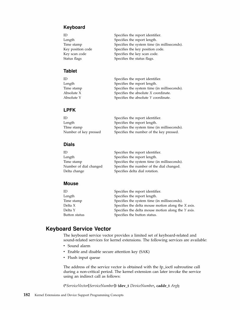
Keyboard
ID Specifies the report identifier.
Length Specifies the report length.
Time stamp Specifies the system time (in milliseconds).
Key position code Specifies the key position code.
Key scan code Specifies the key scan code.
Status flags Specifies the status flags.
Tablet
ID Specifies the report identifier.
Length Specifies the report length.
Time stamp Specifies the system time (in milliseconds).
Absolute X Specifies the absolute X coordinate.
Absolute Y Specifies the absolute Y coordinate.
LPFK
ID Specifies the report identifier.
Length Specifies the report length.
TIme stamp Specifies the system time (in milliseconds).
Number of key pressed Specifies the number of the key pressed.
Dials
ID Specifies the report identifier.
Length Specifies the report length.
Time stamp Specifies the system time (in milliseconds).
Number of dial changed Specifies the number of the dial changed.
Delta change Specifies delta dial rotation.
Mouse
ID Specifies the report identifier.
Length Specifies the report length.
Time stamp Specifies the system time (in milliseconds).
Delta X Specifies the delta mouse motion along the X axis.
Delta Y Specifies the delta mouse motion along the Y axis.
Button status Specifies the button status.
Keyboard Service VectorThe keyboard service vector provides a limited set of keyboard-related andsound-related services for kernel extensions. The following services are available:
v Sound alarm
v Enable and disable secure attention key (SAK)
v Flush input queue
The address of the service vector is obtained with the fp_ioctl subroutine callduring a non-critical period. The kernel extension can later invoke the serviceusing an indirect call as follows:
(*ServiceVector[ServiceNumber]) (dev_t DeviceNumber, caddr_t Arg);
182 Kernel Extensions and Device Support Programming Concepts
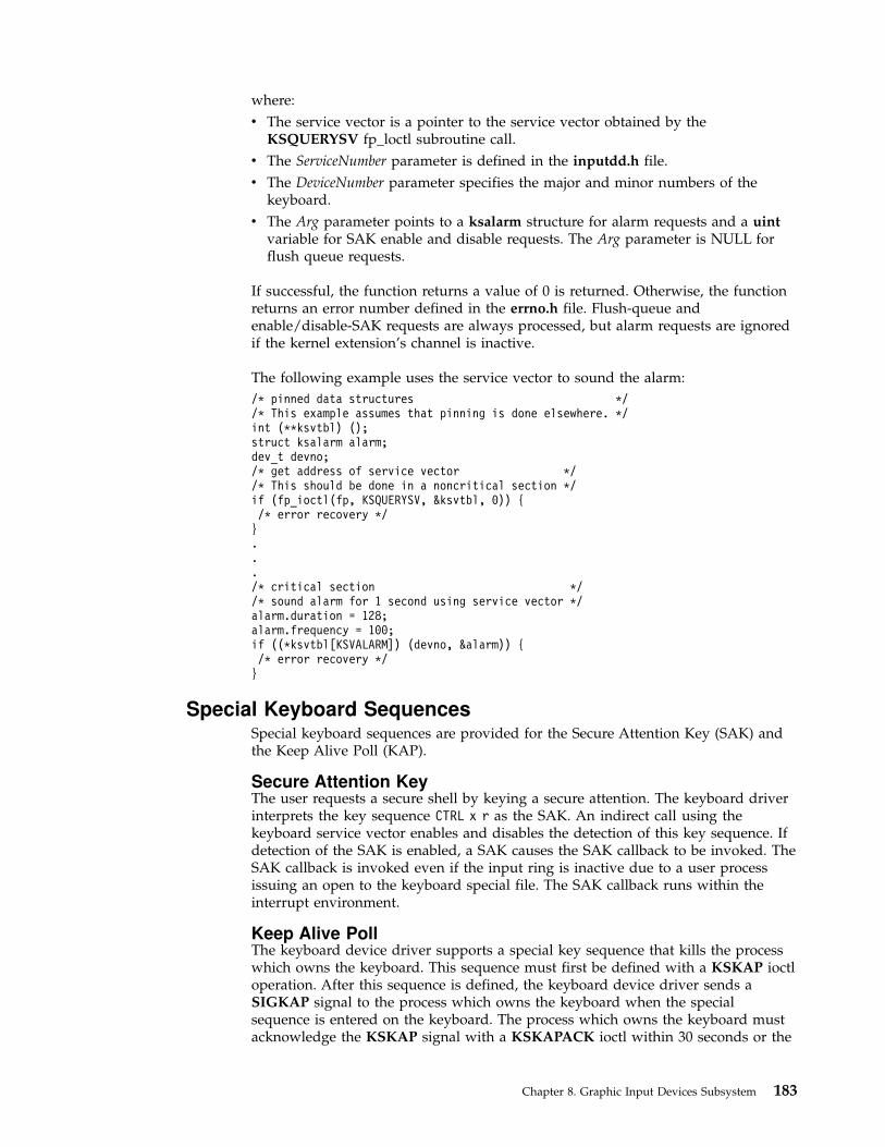
where:
v The service vector is a pointer to the service vector obtained by theKSQUERYSV fp_loctl subroutine call.
v The ServiceNumber parameter is defined in the inputdd.h file.
v The DeviceNumber parameter specifies the major and minor numbers of thekeyboard.
v The Arg parameter points to a ksalarm structure for alarm requests and a uintvariable for SAK enable and disable requests. The Arg parameter is NULL forflush queue requests.
If successful, the function returns a value of 0 is returned. Otherwise, the functionreturns an error number defined in the errno.h file. Flush-queue andenable/disable-SAK requests are always processed, but alarm requests are ignoredif the kernel extension’s channel is inactive.
The following example uses the service vector to sound the alarm:
/* pinned data structures *//* This example assumes that pinning is done elsewhere. */int (**ksvtbl) ();struct ksalarm alarm;dev_t devno;/* get address of service vector *//* This should be done in a noncritical section */if (fp_ioctl(fp, KSQUERYSV, &ksvtbl, 0)) {/* error recovery */}.../* critical section *//* sound alarm for 1 second using service vector */alarm.duration = 128;alarm.frequency = 100;if ((*ksvtbl[KSVALARM]) (devno, &alarm)) {/* error recovery */}
Special Keyboard SequencesSpecial keyboard sequences are provided for the Secure Attention Key (SAK) andthe Keep Alive Poll (KAP).
Secure Attention KeyThe user requests a secure shell by keying a secure attention. The keyboard driverinterprets the key sequence CTRL x r as the SAK. An indirect call using thekeyboard service vector enables and disables the detection of this key sequence. Ifdetection of the SAK is enabled, a SAK causes the SAK callback to be invoked. TheSAK callback is invoked even if the input ring is inactive due to a user processissuing an open to the keyboard special file. The SAK callback runs within theinterrupt environment.
Keep Alive PollThe keyboard device driver supports a special key sequence that kills the processwhich owns the keyboard. This sequence must first be defined with a KSKAP ioctloperation. After this sequence is defined, the keyboard device driver sends aSIGKAP signal to the process which owns the keyboard when the specialsequence is entered on the keyboard. The process which owns the keyboard mustacknowledge the KSKAP signal with a KSKAPACK ioctl within 30 seconds or the
Chapter 8. Graphic Input Devices Subsystem 183

keyboard driver will terminate the process with a SIGKILL signal. The KAP isenabled on a per-channel basis and is unavailable if the channel is owned by akernel extension.
184 Kernel Extensions and Device Support Programming Concepts

Chapter 9. Low Function Terminal Subsystem
This chapter discusses the following topics:
v “Low Function Terminal Interface Functional Description”
v “Components Affected by the Low Function Terminal Interface” on page 186
v “Accented Characters” on page 188
The low function terminal (lft) interface is a pseudo device driver that interfaceswith device drivers for the system keyboard and display adapters. Beginning withAIX Version 4.1, the lft interface adheres to all standard requirements for pseudodevice drivers and has all the entry points and configuration code as required bythe AIX Version 4.1 (or later) device driver architecture. This section gives ahigh-level description of the various configuration methods and entry pointsprovided by the lft interface.
All the device drivers controlled by the lft interface are also used by AIXwindows.Consequently, along with the functions required for the tty sybsystem interface, thelft interface provides the functions required by AIXwindows interfaces withdisplay device driver adapters.
Low Function Terminal Interface Functional Description
Configuration
The lft interface uses the common define, undefine, and unconfig methodsstandard for most devices.
Note: The lft interface does not support any change method for dynamicallychanging the lft configuration. Instead, use the -P flag with the chdevcommand. The changes become effective the next time the lft interface isconfigured.
The configuration process for the lft opens all display device drivers. To define thedefault display and console, select the default display and console during theconsole configuration process. If a graphics display is chosen as the systemconsole, it automatically becomes the default display. The lft interface displays texton the default display.
The configuration process for the lft interface queries the ODM database for theavailable fonts and software keyboard map for the current session.
Terminal Emulation
The lft interface is a stream-based tty subsystem. The lft interface provides VT100(or IBM 3151) terminal emulation for the standard part of the ANSI 3.64 datastream. All line discipline handling is performed in the layers above the lftinterface. The lft interface does not support virtual terminals.
The lft interface supports multiple fonts to handle the different screen sizes andresolutions necessary in providing a 25x80 character display on various displayadapters.
© Copyright IBM Corp. 1997, 1999 185

Note: Applications requiring hft extensions need to use aixterm.
IOCTLS Needed for AIXwindow Support
AIXwindows and the lft interface share the system keyboard and display devicedrivers. To prevent screen and keyboard inconsistencies, a set of ioctls coordinatesusage between AIXwindows and the lft interface. On a system with multipledisplays, the lft interface can still use the default display as long as AIXwindows isusing another display.
Note: The lft interface provides ioctl support to set and change the defaultdisplay.
Low Function Terminal to System Keyboard Interface
The lft interface with the system keyboard uses an input ring mechanism. Thedetails of the keyboard driver ioctls, as well as the format and description of thisinput ring, are provided in the “Chapter 8. Graphic Input Devices Subsystem” onpage 179. The keyboard device driver passes raw keystrokes to the lft interface.These keystrokes are converted to the appropriate code point using keyboardtables. The use of keyboard-language-dependent keyboard tables ensures that thelft interface provides National Language Support.
Note: The keystroke conversion and the keyboard tables are the same used bythe hft interface in AIX Version 3.
Low Function Terminal to Display Device Driver Interface
The lft uses a device independent interface known as the virtual display driver(vdd) interface. Because the lft interface has no virtual terminal or monitor modesupport, some of the vdd entry points are not used by the lft.
The display drivers might enqueue font request through the font process startedduring lft initialization. The font process pins and unpins the requested fonts forDMA to the display adapter.
Low Function Terminal Device Driver Entry Points
The lft interface supports the open, close, read, write, ioctl, and configuration entrypoints.
Components Affected by the Low Function Terminal Interface
Configuration User Commands
The lft interface is a pseudo device driver. Consequently, the system configurationprocess does not detect the lft interface as it does an adapter. The system providesfor pseudo device drivers to be started through Config_Rules. To start the lftinterface, use the startlft program.
Supported commands include:
v lsfont
v mkfont
186 Kernel Extensions and Device Support Programming Concepts

v chfont
v lskbd
v chkbd
v lsdisp (see note)
v chdisp (see note)
Notes:
1. lsdisp outputs the logical device name instead of the instance number.
2. chdisp uses the ioctl interface to the lft to set the requested display.
Display Device Driver
Beginning with AIX Version 4.1, a display device driver is required for eachsupported display adapter.
The display device drivers provide all the standard interfaces (such as config,initialize, terminate, and so forth) required in any AIX Version 4.1 (or later) devicedrivers. The only device switch table entries supported are open, close, config, andioctl. All other device switch table entries are set to nodev. In addition, the displaydevice drivers provide a set of ioctls for use by AIXwindows and diagnostics toperform device specific functions such as get bus access, bus memory address,DMA operations, and so forth.
Rendering Context Manager
The Rendering Context Manager (RCM) is a loadable module.
Note: Previously, the hft interface provided AIXwindows with thegsc_handle. This handle is used in all of the aixgsc system calls. The RCMprovides this service for the lft interface.
To ensure that lft can recover the display in case AIXwindows should terminateabnormally, AIXwindows issues the ioctl to RCM after opening the pseudo device.RCM passes on the ioctl to the lft. This way, the close function in RCM is invoked(Because AIXwindows is the only application that has opened RCM), and RCMnotifies the lft interface to start reusing the display. To support this communication,the RCM provides the required ioctl support.
The RCM to lft Interface Initialization:1. RCM performs the open /dev/lft.
2. Upon receiving a list of displays from X, RCM passes the information to the lftthrough an ioctl.
3. RCM resets the adapter.
If AIXwindows terminates abnormally:1. RCM receives notification from X about the displays it was using.
2. RCM resets the adapter.
3. RCM passes the information to the lft via an ioctl.
The AIXwindows to lft Initialization includes:1. AIXwindows opens /dev/rcm.
2. AIXwindows gets the gsc_handle from RCM via an ioctl.
Chapter 9. Low Function Terminal Subsystem 187
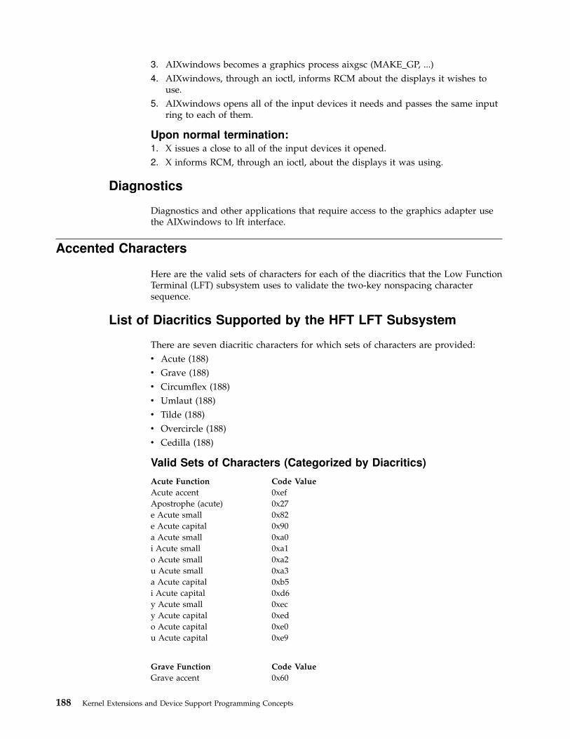
3. AIXwindows becomes a graphics process aixgsc (MAKE_GP, ...)
4. AIXwindows, through an ioctl, informs RCM about the displays it wishes touse.
5. AIXwindows opens all of the input devices it needs and passes the same inputring to each of them.
Upon normal termination:1. X issues a close to all of the input devices it opened.
2. X informs RCM, through an ioctl, about the displays it was using.
Diagnostics
Diagnostics and other applications that require access to the graphics adapter usethe AIXwindows to lft interface.
Accented Characters
Here are the valid sets of characters for each of the diacritics that the Low FunctionTerminal (LFT) subsystem uses to validate the two-key nonspacing charactersequence.
List of Diacritics Supported by the HFT LFT Subsystem
There are seven diacritic characters for which sets of characters are provided:
v Acute (188)
v Grave (188)
v Circumflex (188)
v Umlaut (188)
v Tilde (188)
v Overcircle (188)
v Cedilla (188)
Valid Sets of Characters (Categorized by Diacritics)
Acute Function Code Value
Acute accent 0xef
Apostrophe (acute) 0x27
e Acute small 0x82
e Acute capital 0x90
a Acute small 0xa0
i Acute small 0xa1
o Acute small 0xa2
u Acute small 0xa3
a Acute capital 0xb5
i Acute capital 0xd6
y Acute small 0xec
y Acute capital 0xed
o Acute capital 0xe0
u Acute capital 0xe9
Grave Function Code Value
Grave accent 0x60
188 Kernel Extensions and Device Support Programming Concepts

Grave Function Code Value
a Grave small 0x85
e Grave small 0x8a
i Grave small 0x8d
o Grave small 0x95
u Grave small 0x97
a Grave capital 0xb7
e Grave capital 0xd4
i Grave capital 0xde
o Grave capital 0xe3
u Grave capital 0xeb
Circumflex Function Code Value
| Circumflex accent 0x5e
a Circumflex small 0x83
e Circumflex small 0x88
i Circumflex small 0x8c
o Circumflex small 0x93
u Circumflex small 0x96
a Circumflex capital 0xb6
e Circumflex capital 0xd2
i Circumflex capital 0xd7
o Circumflex capital 0xe2
u Circumflex capital 0xea
Umlaut Function Code Value
Umlaut accent 0xf9
u Umlaut small 0x81
a Umlaut small 0x84
e Umlaut small 0x89
i Umlaut small 0x8b
a Umlaut capital 0x8e
O Umlaut capital 0x99
u Umlaut capital 0x9a
e Umlaut capital 0xd3
i Umlaut capital 0xd8
Tilde Function Code Value
Tilde accent 0x7e
n Tilde small 0xa4
n Tilde capital 0xa5
a Tilde small 0xc6
a Tilde capital 0xc7
o Tilde small 0xe4
o Tilde capital 0xe5
Overcircle Function Code Value
Overcircle accent 0x7d
a Overcircle small 0x86
a Overcircle capital 0x8f
Cedilla Function Code Value
Cedilla accent 0xf7
c Cedilla capital 0x80
c Cedilla small 0x87
Chapter 9. Low Function Terminal Subsystem 189

190 Kernel Extensions and Device Support Programming Concepts

Chapter 10. Logical Volume Subsystem
Logical volume subsystem provides flexible access and control for complexphysical storage systems.
The following topics describe how the logical volume device driver (LVDD)interacts with physical volumes:
v Logical Volume Subsystem
– “Direct Access Storage Devices (DASDs)”
– “Physical Volumes”
v Understanding the Logical Volume Device Driver
– “Interface to Physical Disk Device Drivers” on page 198
v “Understanding Logical Volumes and Bad Blocks” on page 199
v “Changing the mwcc_entries Variable” on page 200
Direct Access Storage Devices (DASDs)
Direct access storage devices (DASDs) are fixed or removable storage devices.Typically, these devices are hard disks. A fixed storage device is any storage devicedefined during system configuration to be an integral part of the system DASD.The operating system detects an error if a fixed storage device is not available atsome time during normal operation.
A removable storage device is any storage device defined by the person whoadministers your system during system configuration to be an optional part of thesystem DASD. The removable storage device can be removed from the system atany time during normal operation. As long as the device is logically unmountedfirst, the operating system does not detect an error.
The following types of devices are not considered DASD and are not supported bythe logical volume manager (LVM):
v Diskettes
v CD-ROM (compact disk read-only memory)
v WORM (write-once read-many)
For a description of the DASD device block level, see “DASD Device Block LevelDescription” on page 299.
Physical Volumes
A logical volume is a portion of a physical volume viewed by the system as avolume. Logical records are records defined in terms of the information theycontain rather than physical attributes.
A physical volume is a DASD structured for requests at the physical level, that is,the level at which a processing unit can request device-independent operations ona physical block address basis. A physical volume is composed of the following:
v A device-dependent reserved area
v A variable number of physical blocks that serve as DASD descriptors
© Copyright IBM Corp. 1997, 1999 191

v An integral number of partitions, each containing a fixed number of physicalblocks
When performing I/O at a physical level, no bad-block relocation is supported.Bad blocks are not hidden at this level as they are at the logical level (see“Understanding Logical Volumes and Bad Blocks” on page 199). Typical operationsat the physical level are read-physical-block and write-physical-block.
The following are terms used when discussing DASD volumes:
block A contiguous, 512-byte region of a physical volume that corresponds in sizeto a DASD sector
partition A set of blocks (with sequential cylinder, head, and sector numbers)contained within a single physical volume
The number of blocks in a partition, as well as the number of partitions in a givenphysical volume, are fixed when the physical volume is installed in a volumegroup. Every physical volume in a volume group has exactly the same partitionsize. There is no restriction on the types of DASDs (for example, Small ComputerSystems Interface (SCSI), Enhanced Small Device Interface (ESDI), or IPI) that canbe placed in a given volume group.
Note: A given physical volume must be assigned to a volume group beforethat physical volume can be used by the LVM.
Physical Volume Implementation Limitations
When composing a physical volume from a DASD, the following implementationrestrictions apply to DASD characteristics:
v 1 to 32 physical volumes per volume group
v The partition size is restricted to 2**n bytes, for 20 <= n <= 30
v The physical block size is restricted to 512 bytes
Physical Volume Layout
A physical volume consists of a logically contiguous string of physical sectors.Sectors are numbered 0 through the last physical sector number (LPSN) on thephysical volume. The total number of physical sectors on a physical volume isLPSN + 1. The actual physical location and physical order of the sectors aretransparent to the sector numbering scheme.
Note: Sector numbering applies to user-accessible data sectors only. Sparesectors and Customer-Engineer (CE) sectors are not included. CE sectors arereserved for use by diagnostic test routines or microcode.
Reserved Sectors on a Physical Volume
A physical volume reserves the first 128 sectors to store various types of DASDconfiguration and operation information. The /usr/include/sys/hd_psn.h filedescribes the information stored on the reserved sectors. The locations of the itemsin the reserved area are expressed as physical sector numbers in this file, and thelengths of those items are in number of sectors.
192 Kernel Extensions and Device Support Programming Concepts

The 128-sector reserved area of a physical volume includes a boot record, thebad-block directory, the LVM record, and the mirror write consistency (MWC)record. The boot record consists of one sector containing information that allowsthe read-only system (ROS) to boot the system. A description of the boot recordcan be found in the /usr/include/sys/bootrecord.h file.
The boot record also contains the pv_id field. This field is a 64-bit numberuniquely identifying a physical volume. This identifier is assigned by themanufacturer of the physical volume. However, if a physical volume is part of avolume group, the pv_id field may be assigned by the LVM.
The bad-block directory records the blocks on the physical volume that have beendiagnosed as unusable (see “Understanding Logical Volumes and Bad Blocks” onpage 199). The structure of the bad-block directory and its entries can be found inthe /usr/include/sys/bbdir.h file.
The LVM record consists of one sector and contains information used by the LVMwhen the physical volume is a member of the volume group. The LVM record isdescribed in the /usr/include/lvmrec.h file.
The MWC record consists of one sector. It identifies which logical partitions maybe inconsistent if the system is not shut down properly. When the volume group isvaried back online for use, this information is used to make logical partitionsconsistent again.
Sectors Reserved for the Logical Volume Manager (LVM)If a physical volume is part of a volume group, the physical volume is used by theLVM and contains two additional reserved areas. One area contains the volumegroup descriptor area/volume group status area and follows the first 128 reservedsectors. The other area is at the end of the physical volume reserved as a relocationpool for bad blocks that must be software-relocated. Both of these areas aredescribed by the LVM record. The space between these last two reserved areas isdivided into equal-sized partitions.
The volume group descriptor area (VGDA) is divided into the following:
v The volume group header. This header contains general information about thevolume group and a time stamp used to verify the consistency of the VGDA.
v A list of logical volume entries. The logical volume entries describe the statesand policies of logical volumes. This list defines the maximum number of logicalvolumes allowed in the volume group. The maximum is specified when avolume group is created.
v A list of physical volume entries. The size of the physical volume list is variablebecause the number of entries in the partition map can vary for each physicalvolume. For example, a 200 MB physical volume with a partition size of 1 MBhas 200 partition map entries.
v A name list. This list contains the special file names of each logical volume inthe volume group.
v A volume group trailer. This trailer contains an ending time stamp for thevolume group descriptor area.
When a volume group is varied online, a majority (also called a quorum) ofVGDAs must be present to perform recovery operations unless you have specifiedthe force flag. (The vary-on operation, performed by using the varyonvgcommand, makes a volume group available to the system.) See ″Logical Volume
Chapter 10. Logical Volume Subsystem 193
Storage Overview″ in AIX Version 4.3 System Management Guide: Operating Systemand Devices for introductory information about the vary-on process and quorums.
Note: Use of the force flag can result in data inconsistency.
A volume group with only one physical volume must contain two copies of thephysical volume group descriptor area. For any volume group containing morethan one physical volume, there are at least three on-disk copies of the volumegroup descriptor area. The default placement of these areas on the physical volumeis as follows:
v For the first physical volume installed in a volume group, two copies of thevolume group descriptor area are placed on the physical volume.
v For the second physical volume installed in a volume group, one copy of thevolume group descriptor area is placed on the physical volume.
v For the third physical volume installed in a volume group, one copy of thevolume group descriptor area is placed on the physical volume. The secondcopy is removed from the first volume.
v For additional physical volumes installed in a volume group, one copy of thevolume group descriptor area is placed on the physical volume.
When a vary-on operation is performed, a majority of copies of the volume groupdescriptor area must be able to come online before the vary-on operation isconsidered successful. A quorum ensures that at least one copy of the volumegroup descriptor areas available to perform recovery was also one of the volumegroup descriptor areas that were online during the previous vary-off operation. Ifnot, the consistency of the volume group descriptor area cannot be ensured.
The volume group status area (VGSA) contains the status of all physical volumesin the volume group. This status is limited to active or missing. The VGSA alsocontains the state of all allocated physical partitions (PP) on all physical volumesin the volume group. This state is limited to active or stale. A PP with a stale stateis not used to satisfy a read request and is not updated on a write request.
A PP changes from active to stale after a successful resynchronization of the logicalpartition (LP) that has multiple copies, or mirrors, and is no longer consistent withits peers in the LP. This inconsistency can be caused by a write error or by nothaving a physical volume available when the LP is written to or updated.
A PP changes from stale to active after a successful resynchronization of the LP. Aresynchronization operation issues resynchronization requests starting at thebeginning of the LP and proceeding sequentially through its end. The LVDD readsfrom an active partition in the LP and then writes that data to any stale partitionin the LP. When the entire LP has been traversed, the partition state is changedfrom stale to active.
Normal I/O can occur concurrently in an LP that is being resynchronized.
Note: If a write error occurs in a stale partition while a resynchronization isin progress, that partition remains stale.
If all stale partitions in an LP encounter write errors, the resynchronizationoperation is ended for this LP and must be restarted from the beginning.
The vary-on operation uses the information in the VGSA to initialize the LVDDdata structures when the volume group is brought online.
194 Kernel Extensions and Device Support Programming Concepts
Understanding the Logical Volume Device Driver
The Logical Volume Device Driver (LVDD) is a pseudo-device driver that operateson logical volumes through the /dev/lvn special file. Like the physical disk devicedriver, this pseudo-device driver provides character and block entry points withcompatible arguments. Each volume group has an entry in the kernel deviceswitch table. Each entry contains entry points for the device driver and a pointer tothe volume group data structure. The logical volumes of a volume group aredistinguished by their minor numbers.
Note: Each logical volume has a control block located in the first 512 bytes.Data begins in the second 512-byte block. Care must be taken when readingand writing directly to the logical volume, such as when using applicationsthat write to raw logical volumes, because the control block is not protectedfrom such writes. If the control block is overwritten, commands that use itcan no longer be used.
Character I/O requests are performed by issuing a read or write request on a/dev/rlvn character special file for a logical volume. The read or write is processedby the file system SVC handler, which calls the LVDD ddread or ddwrite entrypoint. The ddread or ddwrite entry point transforms the character request into ablock request. This is done by building a buffer for the request and calling theLVDD ddstrategy entry point.
Block I/O requests are performed by issuing a read or write on a block special file/dev/lvn for a logical volume. These requests go through the SVC handler to thebread or bwrite block I/O kernel services. These services build buffers for therequest and call the LVDD ddstrategy entry point. The LVDD ddstrategy entrypoint then translates the logical address to a physical address (handling bad blockrelocation and mirroring) and calls the appropriate physical disk device driver.
On completion of the I/O, the physical disk device driver calls the iodone kernelservice on the device interrupt level. This service then calls the LVDD I/Ocompletion-handling routine. Once this is completed, the LVDD calls the iodoneservice again to notify the requester that the I/O is completed.
The LVDD is logically split into top and bottom halves. The top half contains theddopen, ddclose, ddread, ddwrite, ddioctl, and ddconfig entry points. The bottomhalf contains the ddstrategy entry point, which contains block read and write code.This is done to isolate the code that must run fully pinned and has no access touser process context. The bottom half of the device driver runs on interrupt levelsand is not permitted to page fault. The top half runs in the context of a processaddress space and can page fault.
Data Structures
The interface to the ddstrategy entry point is one or more logical buf structures ina list. The logical buf structure is defined in the /usr/include/sys/buf.h file andcontains all needed information about an I/O request, including a pointer to thedata buffer. The ddstrategy entry point associates one or more (if mirrored)physical buf structures (or pbufs) with each logical buf structure and passes themto the appropriate physical device driver.
Chapter 10. Logical Volume Subsystem 195

The pbuf structure is a standard buf structure with some additional fields. TheLVDD uses these fields to track the status of the physical requests that correspondto each logical I/O request. A pool of pinned pbuf structures is allocated andmanaged by the LVDD.
There is one device switch entry for each volume group defined on the system.Each volume group entry contains a pointer to the volume group data structuredescribing it.
Top Half of LVDD
The top half of the LVDD contains the code that runs in the context of a processaddress space and can page fault. It contains the following entry points:
ddopen Called by the file system when a logical volume is mounted, to open thelogical volume specified.
ddclose Called by the file system when a logical volume is unmounted, to close thelogical volume specified.
ddconfig Initializes data structures for the LVDD.
ddread Called by the read subroutine to translate character I/O requests to block I/Orequests. This entry point verifies that the request is on a 512-byte boundaryand is a multiple of 512 bytes in length.
When a character request spans partitions or logical tracks (32 pages of 4Kbytes each), the LVDD ddread routine breaks it into multiple requests. Theroutine then builds a buffer for each request and passes it to the LVDDddstrategy entry point, which handles logical block I/O requests.
If the ext parameter is set (called by the readx subroutine), the ddread entrypoint passes this parameter to the LVDD ddstrategy routine in the b_optionsfield of the buffer header.
ddwrite Called by the write subroutine to translate character I/O requests to block I/Orequests. The LVDD ddwrite routine performs the same processing for a writerequest as the LVDD ddread routine does for read requests.
ddioctl Supports the following operations:
CACLNUPCauses the mirror write consistency (MWC) cache to be written to allphysical volumes (PVs) in a volume group.
IOCINFO, XLATE, GETVGSAReturn LVM configuration information and PP status information.
LV_INFOProvides information about a logical volume. This ioctl operation isavailable beginning with AIX Version 4.2.1.
PBUFCNTIncreases the number of physical buffer headers (pbufs) in the LVMpbuf pool.
Bottom Half of the LVDD
The bottom half of the device driver supports the ddstrategy entry point. Thisentry point processes all logical block requests and performs the followingfunctions:
v Validates I/O requests.
196 Kernel Extensions and Device Support Programming Concepts

v Checks requests for conflicts (such as overlapping block ranges) with requestscurrently in progress.
v Translates logical addresses to physical addresses.
v Handles mirroring and bad-block relocation.
The bottom half of the LVDD runs on interrupt levels and, as a result, is notpermitted to page fault. The bottom half of the LVDD is divided into the followingthree layers:
v “Strategy Layer”
v “Scheduler Layer”
v “Physical Layer”
Each logical I/O request passes down through the bottom three layers beforereaching the physical disk device driver. Once the I/O is complete, the requestreturns back up through the layers to handle the I/O completion processing ateach layer. Finally, control returns to the original requestor.
Strategy LayerThe strategy layer deals only with logical requests. The ddstrategy entry point iscalled with one or more logical buf structures. A list of buf structures for requeststhat are not blocked are passed to the second layer, the scheduler.
Scheduler LayerThe scheduler layer schedules physical requests for logical operations and handlesmirroring and the MWC cache. For each logical request the scheduler layerschedules one or more physical requests. These requests involve translating logicaladdresses to physical addresses, handling mirroring, and calling the LVDDphysical layer with a list of physical requests.
When a physical I/O operation is complete for one phase or mirror of a logicalrequest, the scheduler initiates the next phase (if there is one). If no more I/Ooperations are required for the request, the scheduler calls the strategy terminationroutine. This routine notifies the originator that the request has been completed.
The scheduler also handles the MWC cache for the volume group. If a logicalvolume is using mirror write consistency, then requests for this logical volume areheld within the scheduling layer until the MWC cache blocks can be updated onthe target physical volumes. When the MWC cache blocks have been updated, therequest proceeds with the physical data write operations.
When MWC is being used, system performance can be adversely affected. This iscaused by the overhead of logging or journalling that a write request is active in alogical track group (LTG) (32 4K-byte pages or 128K bytes). This overhead is formirrored writes only. It is necessary to guarantee data consistency between mirrorsparticularly if the system crashes before the write to all mirrors has beencompleted.
Mirror write consistency can be turned off for an entire logical volume. It can alsobe inhibited on a request basis by turning on the NO_MWC flag as defined in the/usr/include/sys/lvdd.h file.
Physical LayerThe physical layer of the LVDD handles startup and termination of the physicalrequest. The physical layer calls a physical disk device driver’s ddstrategy entry
Chapter 10. Logical Volume Subsystem 197

point with a list of buf structures linked together. In turn, the physical layer iscalled by the iodone kernel service when each physical request is completed.
This layer also performs bad-block relocation and detection/correction of badblocks, when necessary. These details are hidden from the other two layers.
Interface to Physical Disk Device Drivers
Physical disk device drivers adhere to the following criteria if they are to beaccessed by the LVDD:
v Disk block size must be 512 bytes.
v The physical disk device driver needs to accept a list of requests defined by bufstructures, which are linked together by the av_forw field in each buf structure.
v For unrecoverable media errors, physical disk device drivers need to set thefollowing:
– The B_ERROR flag must be set to on (defined in the /usr/include/sys/buf.hfile) in the b_flags field.
– The b_error field must be set to E_MEDIA (defined in the/usr/include/sys/errno.h file).
– The b_resid field must be set to the number of bytes in the request that werenot read or written successfully. The b_resid field is used to determine theblock in error.
Note: For write requests, the LVDD attempts to hardware-relocate thebad block. If this is unsuccessful, then the block is software-relocated.For read requests, the information is recorded and the block is relocatedon the next write request to that block.
v For a successful request that generated an excessive number of retries, the devicedriver can return good data. To indicate this situation it must set the following:
– The b_error field is set to ESOFT; this is defined in the/usr/include/sys/errno.h file.
– The b_flags field has the B_ERROR flag set to on.
– The b_resid field is set to a count indicating the first block in the request thathad excessive retries. This block is then relocated.
v The physical disk device driver needs to accept a request of one block withHWRELOC (defined in the /usr/include/sys/lvdd.h file) set to on in theb_options field. This indicates that the device driver is to perform a hardwarerelocation on this request. If the device driver does not support hardwarerelocation the following should be set:
– The b_error field is set to EIO; this is defined in the /usr/include/sys/errno.hfile.
– The b_flags field has the B_ERROR flag set on.
– The b_resid field is set to a count indicating the first block in the request thathas excessive retries.
v The physical disk device driver should support the system dump interface asdefined.
v The physical disk device driver must support write verification on an I/Orequest. Requests for write verification are made by setting the b_options fieldto WRITEV. This value is defined in the /usr/include/sys/lvdd.h file.
198 Kernel Extensions and Device Support Programming Concepts

Understanding Logical Volumes and Bad Blocks
The physical layer of the LVDD initiates all bad-block processing and isolates all ofthe decision making from the physical disk device driver. This happens so thephysical disk device driver does not need to handle mirroring, which is theduplication of data transparent to the user. (See “Physical Layer” on page 197.)
Relocating Bad BlocksThe physical layer of the logical volume device driver (LVDD) checks eachphysical request to see if there are any known software-relocated bad blocks in therequest. The LVDD determines if a request contains known software-relocated badblocks by hashing the physical address. Then a hash chain of the LVDD defectsdirectory is searched to see if any bad-block entries are in the address range of therequest.
If bad blocks exist in a physical request, the request is split into pieces. The firstpiece contains any blocks up to the relocated block. The second piece contains therelocated block (the relocated address is specified in the bad-block entry) of thedefects directory. The third piece contains any blocks after the relocated block tothe end of the request or to the next relocated block. These separate pieces areprocessed sequentially until the entire request has been satisfied.
Once the I/O for the first of the separate pieces has completed, the iodone kernelservice calls the LVDD physical layer’s termination routine (specified in the b_donefield of the buf structure). The termination routine initiates I/O for the secondpiece of the original request (containing the relocated block), and then for the thirdpiece. When the entire physical operation is completed, the appropriate scheduler’spolicy routine (in the second layer of the LVDD) is called to start the next phase ofthe logical operation.
Detecting and Correcting Bad BlocksIf a logical volume is mirrored, a newly detected bad block is fixed by relocatingthat block. A good mirror is read and then the block is relocated using data fromthe good mirror. With mirroring, the user does not need to know when bad blocksare found. However, the physical disk device driver does log permanent I/O errorsso the user can determine the rate of media surface errors.
When a bad block is detected during I/O, the physical disk device driver sets theerror fields in the buf structure to indicate that there was a media surface error.The physical layer of the LVDD then initiates any bad-block processing that mustbe done.
If the operation was a nonmirrored read, the block is not relocated because thedata in the relocated block is not initialized until a write is performed to the block.To support this delayed relocation, an entry for the bad block is put into the LVDDdefects directory and into the bad-block directory on disk. These entries contain norelocated block address and the status for the block is set to indicate that relocationis desired.
On each I/O request, the physical layer checks whether there are any bad blocks inthe request. If the request is a write and contains a block that is in arelocation-desired state, the request is sent to the physical disk device driverwith safe hardware relocation requested. If the request is a read, a read of theknown defective block is attempted.
Chapter 10. Logical Volume Subsystem 199

If the operation was a read operation in a mirrored LP, a request to read one of theother mirrors is initiated. If the second read is successful, then the read is turnedinto a write request and the physical disk device driver is called with safehardware relocation specified to fix the bad mirror.
If the hardware relocation fails or the device does not support safe hardwarerelocation, the physical layer of the LVDD attempts software relocation. At the endof each volume is a reserved area used by the LVDD as a pool of relocation blocks.When a bad block is detected and the disk device driver is unable to relocate theblock, the LVDD picks the next unused block in the relocation pool and writes tothis new location. A new entry is added to the LVDD defects directory in memory(and to the bad-block directory on disk) that maps the bad-block address to thenew relocation block address. Any subsequent I/O requests to the bad-blockaddress are routed to the relocation address.
Attention: Formatting a fixed disk deletes any data that may be on the disk.Format a fixed disk only when absolutely necessary and preferably afterbacking up all data on the disk.
If you need to format a fixed disk completely (including reinitializing any badblocks), use the formatting function supplied by the diag command. (The diagcommand typically, but not necessarily, writes over all data on a fixed disk. Referto the documentation that comes with the fixed disk to determine the effect offormatting with the diag command.)
Changing the mwcc_entries Variable
The default for the number of the logical volume manager mirror write consistencycache (MWCC) is 62, or 0x3e is the hexadecimal. This number is double theoriginal default and improves the user’s write performance, but it also increasesthe time needed to make all mirrors consistent again at volume-group vary-on timeafter a crash. These variables are all system load-dependent.
Note: This procedure modifies the LVM device driver binary code using theadb command. Care should be taken when following this procedure.
Prerequisite Tasks or Conditionsv You must have root user authority.
Procedure1. Change to the /usr/lib/drivers directory.
2. At the command line, type:
dump -h hd_pin
In the .data section header is the RAWptr file, which contains a hex address.Record this address to be used later. An example hex address is 0x0000fc00.
3. At the command line, type:
dump -n hd_pin | grep mwcc_entries
The second field displayed is the offset for the variable. An example is0x000003f8.
4. Add the hex address found in the RAWptr file to the offset for the variable toget the address of the mwcc_entries variable. For example:
200 Kernel Extensions and Device Support Programming Concepts
0x0000fc00 + 0x000003f8 = 0x0000fff8
5. Make a copy of the hd_pin file by typing the following at the command line:
cp hd_pin hd_pin.orig
6. Use the adb command to modify the hd_pin file binary by typing thefollowing at the command line:
abd -w hd_pin
Note: The adb command issues a warning that the string table is missingor the object is being stripped.
7. Issue the following command in response to the adb command to verify youhave the correct address:
0xADDR/X
where ADDR is the address you generated in step 4.
If the hd_pin file has not been modified in this way, the adb commandresponds with:
ADDR: 3e
If this procedure has been done, the adb command responds with:
ADDR: zz
where zz is the current value, from 0x1 to 0x3e, for the number of MWCCentries. If the value is not between 0x1 and 0x3e, check that you are using thecorrect address.
8. Modify the address to the value you want for the number of MWCC entriesby typing the following at the command line:
0xADDR/W zz
where ADDR is the address derived in step 4 and zz is a hex number between0x1 and 0x3e.
9. Exit the adb command by using the Ctrl-D key sequence.
10. Rebuild the startup logical volume by typing the following at the commandline:
bosboot -a
11. Shut down the system by typing the following at the command line:
shutdown -F
12. Restart the system.
The system runs with the size of the mirror write consistency cache set to thenew value.
Note: The new mwcc_entries value must be from 0x1 to 0x3e, inclusive.Unpredictable results occur if these bounds are violated.
Chapter 10. Logical Volume Subsystem 201

202 Kernel Extensions and Device Support Programming Concepts
Chapter 11. Printer Addition Management Subsystem
If you are configuring a printer for your system, there are basically two types ofprinters: printers already supported by the operating system and new printertypes. ″Printer Support″ in AIX Version 4.3 Guide to Printers and Printing listsprinters that are already supported.
Printer Types Currently Supported
To configure a supported type of printer, you need only to run the mkvirprtcommand to create a customized printer file for your printer. This customizedprinter file, which is in the /var/spool/lpd/pio/@local/custom directory, describesthe specific parameters for your printer. For more information see ″Configuring aPrinter without Adding a Queue″ in AIX Version 4.3 Guide to Printers and Printing.
Printer Types Currently Unsupported
To configure a currently unsupported type of printer, you must develop and add aPredefined printer definition for your printer. This new option is then entered inthe list of available choices when the user selects a printer to configure for thesystem. The actual data used by the printer subsystem comes from the Customizedprinter definition created by the mkvirprt command.
“Adding a New Printer Type to Your System” provides general instructions foradding an undefined printer. To add an undefined printer, you modify an existingprinter definition. Undefined printers fall into two categories:
v Printers that closely emulate a supported printer. You can use SMIT or thevirtual printer commands to make the changes you need.
v Printers that do not emulate a supported printer or that emulate several datastreams. It is simpler to make the necessary changes for these printers by editingthe printer colon file. See ″Adding a Printer Using the Printer Colon File″ in AIXVersion 4.3 Guide to Printers and Printing.
“Adding an Unsupported Device to the System” on page 92 offers an overview ofthe major steps required to add an unsupported device of any type to your system.
Adding a New Printer Type to Your System
To add an unsupported printer to your system, you must add a new Printerdefinition to the printer directories. For more complicated scenarios, you mightalso need to add a new printer-specific formatter to the printer backend.
″Example of Print Formatter″ in AIX Version 4.3 Guide to Printers and Printingshows how the print formatter interacts with the printer formatter subroutines.
Additional Steps for Adding a New Printer TypeHowever, if you want the new Printer definition to carry the name of the newprinter, you must develop a new Predefined definition to carry the new printerinformation besides adding a new Printer definition. Use the piopredef commandto do this.
© Copyright IBM Corp. 1997, 1999 203

Steps for adding a new printer-specific formatter to the printer backend arediscussed in “Adding a Printer Formatter to the Printer Backend” on page 205.″Example of Print Formatter″ in AIX Version 4.3 Guide to Printers and Printingshows how print formatters can interact with the printer formatter subroutines.
Note: These instructions apply to the addition of a new printer definition tothe system, not to the addition of a physical printer device itself. Forinformation on adding a new printer device, refer to device configuration andmanagement. If your new printer requires an interface other than the parallelor serial interface provided by the operating system, you must also provide anew device driver.
If the printer being added does not emulate a supported printer or if it emulatesseveral data streams, you need to make more changes to the Printer definition. It issimpler to make the necessary changes for these printers by editing the printercolon file. See ″Adding a Printer Using the Printer Colon File″ in AIX Version 4.3Guide to Printers and Printing.
Modifying Printer Attributes
Edit the customized file ( /var/spool/lpd/pio/custom/var/spool/lpd/pio/@local/custom QueueName:QueueDeviceName), adding or changingthe printer attributes to match the new printer.
For example, assume that you created a new file based on the existing 4201-3printer. The customized file for the 4201-3 printer contains the following templatethat the printer formatter uses to initialize the printer:
%I[ez,em,eA,cv,eC,eO,cp,cc, . . .
The formatter fills in the string as directed by this template and sends the resultingsequence of commands to the 4201-3 printer. Specifically, this generates a string ofescape sequences that initialize the printer and set such parameters as vertical andhorizontal spacing and page length. You would construct a similar command stringto properly initialize the new printer and put it into 4201-emulation mode. Whilemany of the escape sequences might be the same, at least one will be different: theescape sequence that is the command to put the printer into the specificprinter-emulation mode. Assume that you added an ep attribute that specifies thestring to initialize the printer to 4201-3 emulation mode, as follows:
\033\012\013
The Printer Initialization field will then be:
%I[ep,ez,em,eA,cv,eC,eO,cp,cc, . . .
You must create a virtual printer for each printer-emulation mode you want to use.See ″Real and Virtual Printers″ in AIX Version 4.3 Guide to Printers and Printing.
Adding a Printer Definition
To add a new printer to the system, you must first create a description of theprinter by adding a new printer definition to the printer definition directories.
Typically, to add a new printer definition to the database, you first modify anexisting printer definition and then create a customized printer definition in theCustomized Printer Directory.
204 Kernel Extensions and Device Support Programming Concepts

Once you have added the new customized printer definition to the directory, themkvirprt command uses it to present the new printer as a choice for printeraddition and selection. Since the new printer definition is a customized printerdefinition, it appears in the list of printers under the name of the original printerfrom which it was customized.
A totally new printer must be added as a predefined printer definition in the/usr/lib/lpd/pio/predef directory. If the user chooses to work with printers oncethis new predefined printer definition is added to the Predefined Printer Directory,the mkvirprt command can then list all the printers in that directory. The addedprinter appears on the list of printers given to the user as if it had been supportedall along. Specific information about this printer can then be extended, added,modified, or deleted, as necessary.
″Printer Support″ in AIX Version 4.3 Guide to Printers and Printing lists thesupported printer types and names of representative printers.
Adding a Printer Formatter to the Printer Backend
If your new printer’s data stream differs significantly from one of the numerousprinter data streams currently handled by the operating system, you must define anew backend formatter. Adding a new formatter does not require the addition of anew backend. Instead, all you typically need are modifications to the formattercommands associated with that printer under the supervision of the existingprinter backend. If a new backend is required, see ″Printer Backend Overview forProgramming″ in AIX Version 4.3 Guide to Printers and Printing.
Understanding Embedded References in Printer Attribute Strings
The attribute string retrieved by the piocmdout, piogetstr, and piogetvalssubroutines can contain embedded references to other attribute strings or integers.The attribute string can also contain embedded logic that dynamically determinesthe content of the constructed string. This allows the constructed string to reflectthe state of the formatter environment when one of these subroutines is called.
Embedded references and logic are defined with escape sequences that are placedat appropriate locations in the attribute string. The first character of each escapesequence is always the % character. This character indicates the beginning of anescape sequence. The second character (and sometimes subsequent characters)define the operation to be performed. The remainder of the characters (if any) inthe escape sequence are operands to be used in performing the specified operation.
The escape sequences that can be specified in an attribute string are based on theterminfo parameterized string escape sequences for terminals. These escapesequences have been modified and extended for printers.
The attribute names that can be referenced by attribute strings are:
v The names of all attribute variables (which can be integer or string variables)defined to the piogetvals subroutine. When references are made to thesevariables, the piogetvals-defined versions are the values used.
v All other attributes names in the database. These attributes are considered stringconstants.
Chapter 11. Printer Addition Management Subsystem 205

Any attribute value (integer variable, string variable, or string constant) can bereferenced by any attribute string. Consequently, it is important that the formatterensures that the values for all the integer variables and string variables defined tothe piogetvals subroutine are kept current.
The formatter must not assume that the particular attribute string whose name itspecifies to the piogetstr or piocmdout subroutine does not reference certainvariables. The attribute string is retrieved from the database that is external to theformatter. The values in the database represented by the string can be changed toreference additional variables without the formatter’s knowledge.
206 Kernel Extensions and Device Support Programming Concepts

Chapter 12. Small Computer System Interface Subsystem
This overview describes the interface between a small computer system interface(SCSI) device driver and a SCSI adapter device driver. It is directed toward thosewishing to design and write a SCSI device driver that interfaces with an existingSCSI adapter device driver. It is also meant for those wishing to design and write aSCSI adapter device driver that interfaces with existing SCSI device drivers.
SCSI Subsystem Overview
The main topics covered in this overview are:
v “Responsibilities of the SCSI Adapter Device Driver”
v “Responsibilities of the SCSI Device Driver”
v “Initiator-Mode Support” on page 208
v “Target-Mode Support” on page 208
This section frequently refers to both a SCSI device driver and a SCSI adapter devicedriver. These two distinct device drivers work together in a layered approach tosupport attachment of a range of SCSI devices. The SCSI adapter device driver isthe lower device driver of the pair, and the SCSI device driver is the upper devicedriver.
Responsibilities of the SCSI Adapter Device DriverThe SCSI adapter device driver (the lower layer) is the software interface to thesystem hardware. This hardware includes the SCSI bus hardware plus any othersystem I/O hardware required to run an I/O request. The SCSI adapter devicedriver hides the details of the I/O hardware from the SCSI device driver. Thedesign of the software interface allows a user with limited knowledge of thesystem hardware to write the upper device driver.
The SCSI adapter device driver manages the SCSI bus but not the SCSI devices. Itcan send and receive SCSI commands, but it cannot interpret the contents of thecommand. The lower driver also provides recovery and logging for errors relatedto the SCSI bus and system I/O hardware. Management of the device specifics isleft to the SCSI device driver. The interface of the two drivers allows the upperdriver to communicate with different SCSI bus adapters without requiring specialcode paths for each adapter.
Responsibilities of the SCSI Device Driver
The SCSI device driver (the upper layer) provides the rest of the operating systemwith the software interface to a given SCSI device or device class. The upper layerrecognizes which SCSI commands are required to control a particular SCSI deviceor device class. The SCSI device driver builds I/O requests containing device SCSIcommands and sends them to the SCSI adapter device driver in the sequenceneeded to operate the device successfully. The SCSI device driver cannot manageadapter resources or give the SCSI command to the adapter. Specifics about theadapter and system hardware are left to the lower layer.
© Copyright IBM Corp. 1997, 1999 207

The SCSI device driver also provides recovery and logging for errors related to theSCSI device it controls.
The operating system provides several kernel services allowing the SCSI devicedriver to communicate with SCSI adapter device driver entry points withouthaving the actual name or address of those entry points. The description containedin “Logical File System Kernel Services” on page 51 can provide more information.
Communication between SCSI Devices
When two SCSI devices communicate, one assumes the initiator-mode role, and theother assumes the target-mode role. The initiator-mode device generates the SCSIcommand, which requests an operation, and the target-mode device receives theSCSI command and acts. It is possible for a SCSI device to perform both rolessimultaneously.
When writing a new SCSI adapter device driver, the writer must know whichmode or modes must be supported to meet the requirements of the SCSI adapterand any interfaced SCSI device drivers. When a SCSI adapter device driver isadded so that a new SCSI adapter works with all existing SCSI device drivers, bothinitiator-mode and target-mode must be supported in the SCSI adapter devicedriver.
Initiator-Mode SupportThe interface between the SCSI device driver and the SCSI adapter device driverfor initiator-mode support (that is, the attached device acts as a target) is accessedthrough calls to the SCSI adapter device driver open, close, ioctl, and strategyroutines. I/O requests are queued to the SCSI adapter device driver through callsto its strategy entry point.
Communication between the SCSI device driver and the SCSI adapter devicedriver for a particular initiator I/O request is made through the sc_buf structure(see “Understanding the sc_buf Structure” on page 218), which is passed to andfrom the strategy routine in the same way a standard driver uses a struct bufstructure.
Target-Mode Support
The interface between the SCSI device driver and the SCSI adapter device driverfor target-mode support (that is, the attached device acts as an initiator) is accessedthrough calls to the SCSI adapter device driver open, close, and ioctl subroutines.Buffers that contain data received from an attached initiator device are passed fromthe SCSI adapter device driver to the SCSI device driver, and back again, intm_buf structures.
Communication between the SCSI adapter device driver and the SCSI devicedriver for a particular data transfer is made by passing the tm_buf structures bypointer directly to routines whose entry points have been previously registered.This registration occurs as part of the sequence of commands the SCSI devicedriver executes using calls to the SCSI adapter device driver when the devicedriver opens a target-mode device instance.
208 Kernel Extensions and Device Support Programming Concepts

Understanding SCSI Asynchronous Event Handling
Note: This operation is not supported by all SCSI I/O controllers.
A SCSI device driver can register a particular device instance for receivingasynchronous event status by calling the SCIOEVENT ioctl operation for theSCSI-adapter device driver. When an event covered by the SCIOEVENT ioctloperation is detected by the SCSI adapter device driver, it builds an sc_event_infostructure and passes a pointer to the structure and to the asynchronousevent-handler routine entry point, which was previously registered. The fields inthe structure are filled in by the SCSI adapter device driver as follows:
id For initiator mode, this is set to the SCSI ID of the attached SCSItarget device. For target mode, this is set to the SCSI ID of theattached SCSI initiator device.
lun For initiator mode, this is set to the SCSI LUN of the attached SCSItarget device. For target mode, this is set to 0).
mode Identifies whether the initiator or target mode device is beingreported. The following values are possible:
SC_IM_MODE
An initiator mode device is being reported.
SC_TM_MODE
A target mode device is being reported.
events This field is set to indicate what event or events are being reported.The following values are possible, as defined in the/usr/include/sys/scsi.h file:
SC_FATAL_HDW_ERR
A fatal adapter hardware error occurred.
SC_ADAP_CMD_FAILED
An unrecoverable adapter command failure occurred.
SC_SCSI_RESET_EVENT
A SCSI bus reset was detected.
SC_BUFS_EXHAUSTED
In target-mode, a maximum buffer usage event hasoccurred.
adap_devno This field is set to indicate the device major and minor numbers ofthe adapter on which the device is located.
async_correlator This field is set to the value passed to the SCSI adapter devicedriver in the sc_event_struct structure. The SCSI device driver mayoptionally use this field to provide an efficient means of associatingevent status with the device instance it goes with. Alternatively, theSCSI device driver would use the combination of the id, lun, mode,and adap_devno fields to identify the device instance.
Note: Reserved fields should be set to 0 by the SCSI adapter device driver.
The information reported in the sc_event_info.events field does not queue to theSCSI device driver, but is instead reported as one or more flags as they occur. Sincethe data does not queue, the SCSI adapter device driver writer can use a singlesc_event_info structure and pass it one at a time, by pointer, to each asynchronousevent handler routine for the appropriate device instance. After determining for
Chapter 12. Small Computer System Interface Subsystem 209
which device the events are being reported, the SCSI device driver must copy thesc_event_info.events field into local space and must not modify the contents ofthe rest of the sc_event_info structure.
Since the event status is optional, the SCSI device driver writer determines whataction is necessary to take upon receiving event status. The writer may decide tosave the status and report it back to the calling application, or the SCSI devicedriver or application level program can take error recovery actions.
Defined Events and Recovery ActionsThe adapter fatal hardware failure event is intended to indicate that no furthercommands to or from this SCSI device are likely to succeed, since the adapter it isattached to has failed. It is recommended that the application end the session withthe device.
The unrecoverable adapter command failure event is not necessarily a fatalcondition, but it can indicate that the adapter is not functioning properly. Possibleactions by the application program include:
v Ending of the session with the device in the near future.
v Ending of the session after multiple (two or more) such events.
v Attempt to continue the session indefinitely.
The SCSI Bus Reset detection event is mainly intended as information only, butmay be used by the application to perform further actions, if necessary.
The maximum buffer usage detected event only applies to a given target-modedevice; it will not be reported for an initiator-mode device. This event indicates tothe application that this particular target-mode device instance has filled itsmaximum allotted buffer space. The application should perform read system callsfast enough to prevent this condition. If this event occurs, data is not lost, but it isdelayed to prevent further buffer usage. Data reception will be restored when theapplication empties enough buffers to continue reasonable operations. Thenum_bufs attribute may need to be increased to help minimize this problem. Also,it is possible that regardless of the number of buffers, the application simply is notprocessing received data fast enough. This may require some fine tuning of theapplication’s data processing routines.
Asynchronous Event-Handling Routine
The SCSI-device driver asynchronous event-handling routine is typically calleddirectly from the hardware interrupt-handling routine for the SCSI adapter devicedriver. The SCSI device driver writer must be aware of how this affects the designof the SCSI device driver.
Since the event handling routine is running on the hardware interrupt level, theSCSI device driver must be careful to limit operations in that routine. Processingshould be kept to a minimum. In particular, if any error recovery actions areperformed, it is recommended that the event-handling routine set state or statusflags only and allow a process level routine to perform the actual operations.
The SCSI device driver must be careful to disable interrupts at the correct level inplaces where the SCSI device driver’s lower execution priority routines manipulatevariables that are also modified by the event-handling routine. To allow the SCSIdevice driver to disable at the correct level, the SCSI adapter device driver writer
210 Kernel Extensions and Device Support Programming Concepts

must provide a configuration database attribute that defines the interrupt class, orpriority, it runs on. This attribute must be named intr_priority so that the SCSIdevice driver configuration method knows which attribute of the parent adapter toquery. The SCSI device driver configuration method should then pass this interruptpriority value to the SCSI device driver along with other configuration data for thedevice instance.
The SCSI device driver writer must follow any other general system rules forwriting a routine which must execute in an interrupt environment. For example,the routine must not attempt to sleep or wait on I/O operations. It can performwakeups to allow the process level to handle those operations.
Since the SCSI device driver copies the information from the sc_event_info.eventsfield on each call to its asynchronous event-handling routine, there is no resourceto free or any information which must be passed back later to the SCSI adapterdevice driver.
SCSI Error Recovery
The SCSI error-recovery process handles different issues depending on whether theSCSI device is in initiator mode or target mode. If the device is in initiator mode,the error-recovery process varies depending on whether or not the device issupporting command queuing.
SCSI Initiator-Mode Recovery When Not Command TagQueuing
If an error such as a check condition or hardware failure occurs, transactionsqueued within the SCSI adapter device driver are terminated abnormally withiodone calls. The transaction active during the error is returned with thesc_buf.bufstruct.b_error field set to EIO. Other transactions in the queue arereturned with the sc_buf.bufstruct.b_error field set to ENXIO. The SCSI devicedriver should process or recover the condition, rerunning any mode selects ordevice reservations to recover from this condition properly. After this recovery, itshould reschedule the transaction that had the error. In many cases, the SCSIdevice driver only needs to retry the unsuccessful operation.
The SCSI adapter device driver should never retry a SCSI command on error afterthe command has successfully been given to the adapter. The consequences forretrying a SCSI command at this point range from minimal to catastrophic,depending upon the type of device. Commands for certain devices cannot beretried immediately after a failure (for example, tapes and other sequential accessdevices). If such an error occurs, the failed command returns an appropriate errorstatus with an iodone call to the SCSI device driver for error recovery. Only theSCSI device driver that originally issued the command knows if the command canbe retried on the device. The SCSI adapter device driver must only retrycommands that were never successfully transferred to the adapter. In this case, ifretries are successful, the sc_buf status should not reflect an error. However, theSCSI adapter device driver should perform error logging on the retried condition.
The first transaction passed to the SCSI adapter device driver during errorrecovery must include a special flag. This SC_RESUME flag in the sc_buf.flagsfield must be set to inform the SCSI adapter device driver that the SCSI devicedriver has recognized the fatal error and is beginning recovery operations. Anytransactions passed to the SCSI adapter device driver, after the fatal error occurs
Chapter 12. Small Computer System Interface Subsystem 211

and before the SC_RESUME transaction is issued, should be flushed; that is,returned with an error type of ENXIO through an iodone call.
Note: If a SCSI device driver continues to pass transactions to the SCSIadapter device driver after the SCSI adapter device driver has flushed thequeue, these transactions are also flushed with an error return of ENXIOthrough the iodone service. This gives the SCSI device driver a positiveindication of all transactions flushed.
If the SCSI device driver is executing a gathered write operation, the error-recoveryinformation mentioned previously is still valid, but the caller must restore thecontents of the sc_buf.resvdw1 field and the uio struct that the field pointed tobefore attempting the retry (see “Gathered Write Commands” on page 217). Theretry must occur from the SCSI device driver’s process level; it cannot beperformed from the caller’s iodone subroutine. Also, additional return codes ofEFAULT and ENOMEM are possible in the sc_buf.bufstruct.b_error field for agathered write operation.
SCSI Initiator-Mode Recovery During Command Tag QueuingIf the SCSI device driver is queuing multiple transactions to the device and either acheck condition error or a command terminated error occurs, the SCSI adapterdriver does not clear all transactions in its queues for the device. It returns thefailed transaction to the SCSI device driver with an indication that the queue forthis device is not cleared by setting the SC_DID_NOT_CLEAR_Q flag in thesc_buf.adap_q_status field. The SCSI adapter driver halts the queue for thisdevice awaiting error recovery notification from the SCSI device driver. The SCSIdevice driver then has three options to recover from this error:
v Send one error recovery command (request sense) to the device.
v Clear the SCSI adapter driver’s queue for this device.
v Resume the SCSI adapter driver’s queue for this device.
When the SCSI adapter driver’s queue is halted, the SCSI device drive can getsense data from a device by setting the SC_RESUME flag in the sc_buf.flags fieldand the SC_NO_Q flag in sc_buf.q_tag_msg field of the request-sense sc_buf. Thisaction notifies the SCSI adapter driver that this is an error-recovery transaction andshould be sent to the device while the remainder of the queue for the deviceremains halted. When the request sense completes, the SCSI device driver needs toeither clear or resume the SCSI adapter driver’s queue for this device.
The SCSI device driver can notify the SCSI adapter driver to clear its halted queueby sending a transaction with the SC_Q_CLR flag in the sc_buf.flags field. Thistransaction must not contain a SCSI command because it is cleared from the SCSIadapter driver’s queue without being sent to the adapter. However, this transactionmust have the SCSI ID field (sc_buf.scsi_command.scsi_id) and the LUN fields(sc_buf.scsi_command.scsi_cmd.lun and sc_buf.lun) filled in with the device’sSCSI ID and logical unit number (LUN). If addressing LUNs 8 - 31, the sc_buf.lunfield should be set to the logical unit number and thesc_buf.scsi_command.scsi_cmd.lun field should be zeroed out. See the descriptionsof these fields for further explanation. Upon receiving an SC_Q_CLR transaction,the SCSI adapter driver flushes all transactions for this device and sets theirsc_buf.bufstruct.b_error fields to ENXIO. The SCSI device driver must waituntil the sc_buf with the SC_Q_CLR flag set is returned before it resumes issuingtransactions. The first transaction sent by the SCSI device driver after it receivesthe returned SC_Q_CLR transaction must have the SC_RESUME flag set in thesc_buf.flags fields.
212 Kernel Extensions and Device Support Programming Concepts
If the SCSI device driver wants the SCSI adapter driver to resume its halted queue,it must send a transaction with the SC_Q_RESUME flag set in the sc_buf.flagsfield. This transaction can contain an actual SCSI command, but it is not required.However, this transaction must have the sc_buf.scsi_command.scsi_id,sc_buf.scsi_command.scsi_cmd.lun,and the sc_buf.lun fields filled in with thedevice’s SCSI ID and logical unit number. See the description of these fields forfurther details. If this is the first transaction issued by the SCSI device driver afterreceiving the error (indicating that the adapter driver’s queue is halted), then theSC_RESUME flag must be set as well as the SC_Q_RESUME flag.
Analyzing Returned StatusThe following order of precedence should be followed by SCSI device driverswhen analyzing the returned status:
1. If the sc_buf.bufstruct.b_flags field has the B_ERROR flag set, then an errorhas occurred and the sc_buf.bufstruct.b_error field contains a valid errnovalue.
If the b_error field contains the ENXIO value, either the command needs to berestarted or it was canceled at the request of the SCSI device driver.
If the b_error field contains the EIO value, then either one or no flag is set inthe sc_buf.status_validity field. If a flag is set, an error in either thescsi_status or general_card_status field is the cause.
If the status_validity field is 0, then the sc_buf.bufstruct.b_resid fieldshould be examined to see if the SCSI command issued was in error. Theb_resid field can have a value without an error having occurred. To decidewhether an error has occurred, the SCSI device driver must evaluate this fieldwith regard to the SCSI command being sent and the SCSI device being driven.
If the SCSI device driver is queuing multiple transactions to the device and ifeither SC_CHECK_CONDITION or SC_COMMAND_TERMINATED is set inscsi_status , then the value of sc_buf.adap_q_status must be analyzed todetermine if the adapter driver has cleared its queue for this device. If the SCSIadapter driver has not cleared its queue after an error, then it holds that queuein a halted state.
If sc_buf.adap_q_status is set to 0, the SCSI adapter driver has cleared itsqueue for this device and any transactions outstanding are flushed back to theSCSI device driver with an error of ENXIO.
If the SC_DID_NOT_CLEAR_Q flag is set in the sc_buf.adap_q_status field,the adapter driver has not cleared its queue for this device. When thiscondition occurs, the SCSI adapter driver allows the SCSI device driver to sendone error recovery transaction (request sense) that has the fieldsc_buf.q_tag_msg set to SC_NO_Q and the field sc_buf.flags set toSC_RESUME. The SCSI device driver can then notify the SCSI adapter driverto clear or resume its queue for the device by sending a SC_Q CLR orSC_Q_RESUME transaction.
If the SCSI device driver does not queue multiple transactions to the device(that is, the SC_NO_Q is set in sc_buf.q_tag_msg ), then the SCSI adapterclears its queue on error and sets sc_buf.adap_q_status to 0.
2. If the sc_buf.bufstruct.b_flags field does not have the B_ERROR flag set,then no error is being reported. However, the SCSI device driver shouldexamine the b_resid field to check for cases where less data was transferredthan expected. For some SCSI commands, this occurrence may not represent anerror. The SCSI device driver must determine if an error has occurred.
If a nonzero b_resid field does represent an error condition, then the devicequeue is not halted by the SCSI adapter device driver. It is possible for one or
Chapter 12. Small Computer System Interface Subsystem 213
more succeeding queued commands to be sent to the adapter (and possibly thedevice). Recovering from this situation is the responsibility of the SCSI devicedriver.
3. In any of the above cases, if sc_buf.bufstruct.b_flags field has the B_ERRORflag set, then the queue of the device in question has been halted. The firstsc_buf structure sent to recover the error (or continue operations) must havethe SC_RESUME bit set in the sc_buf.flags field.
Target-Mode Error Recovery
If an error occurs during the reception of send command data, the SCSI adapterdevice driver sets the TM_ERROR flag in the tm_buf.user_flag field. The SCSIadapter device driver also sets the SC_ADAPTER_ERROR bit in thetm_buf.status_validity field and sets a single flag in thetm_buf.general_card_status field to indicate the error that occurred.
In the SCSI subsystem, an error during a send command does not affect futuretarget-mode data reception. Future send commands continue to be processed bythe SCSI adapter device driver and queue up, as necessary, after the data with theerror. The SCSI device driver continues processing the send command data,satisfying user read requests as usual except that the error status is returned forthe appropriate user request. Any error recovery or synchronization procedures theuser requires for a target-mode received-data error must be implemented inuser-supplied software.
A Typical Initiator-Mode SCSI Driver Transaction Sequence
A simplified sequence of events for a transaction between a SCSI device driver anda SCSI adapter device driver follows. In this sequence, routine names preceded bya dd_ are part of the SCSI device driver, while those preceded by a sc_ are part ofthe SCSI adapter device driver.
1. The SCSI device driver receives a call to its dd_strategy routine; any requiredinternal queuing occurs in this routine. The dd_strategy entry point thentriggers the operation by calling the dd_start entry point. The dd_start routineinvokes the sc_strategy entry point by calling the devstrategy kernel servicewith the relevant sc_buf structure as a parameter.
2. The sc_strategy entry point initially checks the sc_buf structure for validity.These checks include validating the devno field, matching the SCSI ID/LUN tointernal tables for configuration purposes, and validating the request size.
3. Although the SCSI adapter device driver cannot reorder transactions, it doesperform queue chaining. If no other transactions are pending for the requesteddevice, the sc_strategy routine immediately calls the sc_start routine with thenew transaction. If there are other transactions pending, the new transaction isadded to the tail of the device chain.
4. At each interrupt, the sc_intr interrupt handler verifies the current status. TheSCSI adapter device driver fills in the sc_buf status_validity field, updatingthe scsi_status and general_card_status fields as required. The SCSI adapterdevice driver also fills in the bufstruct.b_resid field with the number of bytesnot transferred from the request. If all the data was transferred, the b_residfield is set to a value of 0. When a transaction completes, the sc_intr routinecauses the sc_buf entry to be removed from the device queue and calls theiodone kernel service, passing the just dequeued sc_buf structure for the deviceas the parameter. The sc_start routine is then called again to process the next
214 Kernel Extensions and Device Support Programming Concepts

transaction on the device queue. The iodone kernel service calls the SCSIdevice driver dd_iodone entry point, signaling the SCSI device driver that theparticular transaction has completed.
5. The SCSI device driver dd_iodone routine investigates the I/O completioncodes in the sc_buf status entries and performs error recovery, if required. Ifthe operation completed correctly, the SCSI device driver dequeues the originalbuffer structures. It calls the iodone kernel service with the original bufferpointers to notify the originator of the request.
Understanding SCSI Device Driver Internal Commands
During initialization, error recovery, and open or close operations, SCSI devicedrivers initiate some transactions not directly related to an operating systemrequest. These transactions are called internal commands and are relatively simple tohandle.
Internal commands differ from operating system-initiated transactions in severalways. The primary difference is that the SCSI device driver is required to generatea struct buf that is not related to a specific request. Also, the actual SCSIcommands are typically more control-oriented than data transfer-related.
The only special requirement for commands with short data-phase transfers (lessthan or equal to 256 bytes) is that the SCSI device driver must have pinned thememory being transferred into or out of system memory pages. However, due tosystem hardware considerations, additional precautions must be taken for datatransfers into system memory pages when the transfers are larger than 256 bytes.The problem is that any system memory area with a DMA data operation inprogress causes the entire memory page that contains it to become inaccessible.
As a result, a SCSI device driver that initiates an internal command with morethan 256 bytes must have preallocated and pinned an area of some multiple whosesize is the system page size. The driver must not place in this area any other dataareas that it may need to access while I/O is being performed into or out of thatpage. Memory pages so allocated must be avoided by the device driver from themoment the transaction is passed to the adapter device driver until the devicedriver iodone routine is called for the transaction (and for any other transactionsto those pages).
Understanding the Execution of Initiator I/O Requests
During normal processing, many transactions are queued in the SCSI device driver.As the SCSI device driver processes these transactions and passes them to the SCSIadapter device driver, the SCSI device driver moves them to the in-process queue.When the SCSI adapter device driver returns through the iodone service with oneof these transactions, the SCSI device driver either recovers any errors on thetransaction or returns using the iodone kernel service to the calling level.
The SCSI device driver can send only one sc_buf structure per call to the SCSIadapter device driver. Thus, the sc_buf.bufstruct.av_forw pointer should be nullwhen given to the SCSI adapter device driver, which indicates that this is the onlyrequest. The SCSI device driver can queue multiple sc_buf requests by makingmultiple calls to the SCSI adapter device driver strategy routine.
Chapter 12. Small Computer System Interface Subsystem 215
Spanned (Consolidated) CommandsSome kernel operations may be composed of sequential operations to a device. Forexample, if consecutive blocks are written to disk, blocks may or may not be inphysically consecutive buffer pool blocks.
To enhance SCSI bus performance, the SCSI device driver should consolidatemultiple queued requests when possible into a single SCSI command. To allow theSCSI adapter device driver the ability to handle the scatter and gather operationsrequired, the sc_buf.bp should always point to the first buf structure entry for thespanned transaction. A null-terminated list of additional struct buf entries shouldbe chained from the first field through the buf.av_forw field to give the SCSIadapter device driver enough information to perform the DMA scatter and gatheroperations required. This information must include at least the buffer’s startingaddress, length, and cross-memory descriptor.
The spanned requests should always be for requests in either the read or writedirection but not both, since the SCSI adapter device driver must be given a singleSCSI command to handle the requests. The spanned request should always consistof complete I/O requests (including the additional struct buf entries). The SCSIdevice driver should not attempt to use partial requests to reach the maximumtransfer size.
The maximum transfer size is actually adapter-dependent. The IOCINFO ioctloperation can be used to discover the SCSI adapter device driver’s maximumallowable transfer size. To ease the design, implementation, and testing ofcomponents that may need to interact with multiple SCSI-adapter device drivers, arequired minimum size has been established that all SCSI adapter device driversmust be capable of supporting. The value of this minimum/maximum transfer sizeis defined as the following value in the /usr/include/sys/scsi.h file:
SC_MAXREQUEST /* maximum transfer request for a single *//* SCSI command (in bytes) */
If a transfer size larger than the supported maximum is attempted, the SCSIadapter device driver returns a value of EINVAL in the sc_buf.bufstruct.b_errorfield.
Due to system hardware requirements, the SCSI device driver must consolidateonly commands that are memory page-aligned at both their starting and endingaddresses. Specifically, this applies to the consolidation of inner memory buffers.The ending address of the first buffer and the starting address of all subsequentbuffers should be memory page-aligned. However, the starting address of the firstmemory buffer and the ending address of the last do not need to be aligned so.
The purpose of consolidating transactions is to decrease the number of SCSIcommands and bus phases required to perform the required operation. The timerequired to maintain the simple chain of buf structure entries is significantly lessthan the overhead of multiple (even two) SCSI bus transactions.
Fragmented Commands
Single I/O requests larger than the maximum transfer size must be divided intosmaller requests by the SCSI device driver. For calls to a SCSI device driver’scharacter I/O (read/write) entry points, the uphysio kernel service can be used tobreak up these requests. For a fragmented command such as this, the sc_buf.bp field
216 Kernel Extensions and Device Support Programming Concepts

should be null so that the SCSI adapter device driver uses only the information inthe sc_buf structure to prepare for the DMA operation.
Gathered Write Commands
The gathered write commands facilitate communications applications that arerequired to send header and trailer messages with data buffers. These headers andtrailers are typically the same or similar for each transfer. Therefore, there may be asingle copy of these messages but multiple data buffers.
The gathered write commands, accessed through the sc_buf.resvd1 field, differfrom the spanned commands, accessed through the sc_buf.bp field, in severalways:
v Gathered write commands can transfer data regardless of address alignment,while spanned commands must be memory page-aligned in address and length,making small transfers difficult.
v Gathered write commands can be implemented either in software (whichrequires the extra step of copying the data to temporary buffers) or hardware.Spanned commands can be implemented in system hardware due toaddress-alignment requirements. As a result, spanned commands are potentiallyfaster to run.
v Gathered write commands are not able to handle read requests. Spannedcommands can handle both read and write requests.
v Gathered write commands can be initiated only on the process level, butspanned commands can be initiated on either the process or interrupt level.
To execute a gathered write command, the SCSI device driver must:
v Fill in the resvd1 field with a pointer to the uio struct.
v Call the SCSI adapter device driver on the same process level with the sc_bufstructure in question.
v Be attempting a write.
v Not have put a non-null value in the sc_buf.bp field.
If any of these conditions are not met, the gather write commands do not succeedand the sc_buf.bufstruct.b_error is set to EINVAL.
This interface allows the SCSI adapter device driver to perform the gathered writecommands in both software or hardware as long as the adapter supports thiscapability. Because the gathered write commands can be performed in software (byusing such kernel services as uiomove), the contents of the resvd1 field and theuio struct can be altered. Therefore, the caller must restore the contents of both theresvd1 field and the uio struct before attempting a retry. Also, the retry must occurfrom the process level; it must not be performed from the caller’s iodonesubroutine.
To support SCSI adapter device drivers that perform the gathered write commandsin software, additional return values in the sc_buf.bufstruct.b_error field arepossible when gathered write commands are unsuccessful.
ENOMEMError due to lack of system memory to perform copy.
EFAULT Error due to memory copy problem.
Chapter 12. Small Computer System Interface Subsystem 217

Note: The gathered write command facility is optional for both the SCSIdevice driver and the SCSI adapter device driver. Attempting a gatheredwrite command to a SCSI adapter device driver that does not supportgathered write can cause a system crash. Therefore, any SCSI device drivermust issue a SCIOGTHW ioctl operation to the SCSI adapter device driverbefore using gathered writes. A SCSI adapter device driver that supportsgathered writes must support the SCIOGTHW ioctl as well. The ioctl returnsa successful return code if gathered writes are supported. If the ioctl fails, theSCSI device driver must not attempt a gathered write. Typically, a SCSIdevice driver places the SCIOGTHW call in its open routine for deviceinstances that it will send gathered writes to.
SCSI Command Tag Queuing
Note: This operation is not supported by all SCSI I/O controllers.
SCSI command tag queuing refers to queuing multiple commands to a SCSIdevice. Queuing to the SCSI device can improve performance because the deviceitself determines the most efficient way to order and process commands. SCSIdevices that support command tag queuing can be divided into two classes: thosethat clear their queues on error and those that do not. Devices that do not cleartheir queues on error resume processing of queued commands when the errorcondition is cleared (typically by receiving the next command). Devices that doclear their queues flush all commands currently outstanding.
Command tag queueing requires the SCSI adapter, the SCSI device, the SCSIdevice driver, and the SCSI adapter driver to support this capability. For a SCSIdevice driver to queue multiple commands to a SCSI device (that supportscommand tag queuing), it must be able to provide at least one of the followingvalues in the sc_buf.q_tag_msg: SC_SIMPLE_Q, SC_HEAD_OF_Q, orSC_ORDERED_Q. The SCSI disk device driver and SCSI adapter driver dosupport this capability. This implementation provides some queuing-specificchangeable attributes for disks that can queue commands. With this information,the disk device driver attempts to queue to the disk, first by queuing commands tothe adapter driver. The SCSI adapter driver then queues these commands to theadapter, providing that the adapter supports command tag queuing. If the SCSIadapter does not support command tag queuing, then the SCSI adapter driversends only one command at a time to the SCSI adapter and so multiple commandsare not queued to the SCSI disk.
Understanding the sc_buf Structure
The sc_buf structure is used for communication between the SCSI device driverand the SCSI adapter device driver during an initiator I/O request. This structureis passed to and from the strategy routine in the same way a standard driver usesa struct buf structure.
Fields in the sc_buf StructureThe sc_buf structure contains certain fields used to pass a SCSI command andassociated parameters to the SCSI adapter device driver. Other fields within thisstructure are used to pass returned status back to the SCSI device driver. Thesc_buf structure is defined in the /usr/include/sys/scsi.h file.
Fields in the sc_buf structure are used as follows:
218 Kernel Extensions and Device Support Programming Concepts
1. Reserved fields should be set to a value of 0, except where noted.
2. The bufstruct field contains a copy of the standard buf buffer structure thatdocuments the I/O request. Included in this structure, for example, are thebuffer address, byte count, and transfer direction. The b_work field in the bufstructure is reserved for use by the SCSI adapter device driver. The currentdefinition of the buf structure is in the /usr/include/sys/buf.h include file.
3. The bp field points to the original buffer structure received by the SCSI DeviceDriver from the caller, if any. This can be a chain of entries in the case ofspanned transfers (SCSI commands that transfer data from or to more thanone system-memory buffer). A null pointer indicates a nonspanned transfer.The null value specifically tells the SCSI adapter device driver that all theinformation needed to perform the DMA data transfer is contained in thebufstruct fields of the sc_buf structure. If the bp field is set to a non-nullvalue, the sc_buf.resvd1 field must have a value of null, or else the operationis not allowed.
4. The scsi_command field, defined as a scsi structure, contains, for example, theSCSI ID, SCSI command length, SCSI command, and a flag variable:
a. The scsi_length field is the number of bytes in the actual SCSI command.This is normally 6, 10, or 12 (decimal).
b. The scsi_id field is the SCSI physical unit ID.
c. The scsi_flags field contains the following bit flags:
SC_NODISC Do not allow the target to disconnect during this command.
SC_ASYNC Do not allow the adapter to negotiate for synchronous transfer to the SCSIdevice.
During normal use, the SC_NODISC bit should not be set. Setting this bitallows a device executing commands to monopolize the SCSI bus.Sometimes it is desirable for a particular device to maintain control of thebus once it has successfully arbitrated for it; for instance, when this is theonly device on the SCSI bus or the only device that will be in use. Forperformance reasons, it may not be desirable to go through SCSI selectionsagain to save SCSI bus overhead on each command.
Also during normal use, the SC_ASYNC bit must not be set. It should beset only in cases where a previous command to the device ended in anunexpected SCSI bus free condition. This condition is noted asSC_SCSI_BUS_FAULT in the general_card_status field of the sc_cmdstructure. Since other errors may also result in the SC_SCSI_BUS_FAULTflag being set, the SC_ASYNC bit should only be set on the last retry ofthe failed command.
d. The sc_cmd structure contains the physical SCSI command block. The 6 to12 bytes of a single SCSI command are stored in consecutive bytes, withthe op code and logical unit identified individually. The sc_cmd structurecontains the following fields:
v The scsi_op_code field specifies the standard SCSI op code for thiscommand.
v The lun field specifies the standard SCSI logical unit for the physicalSCSI device controller. Typically, there will be one LUN per controller(LUN=0, for example) for devices with imbedded controllers. Only theupper 3 bits of this field contain the actual LUN ID. If addressing LUN’s0 - 7, this lun field should always be filled in with the LUN value.When addressing LUN’s 8 - 31, this lun field should be set to 0 and theLUN value should be placed into the sc_buf.lun field described in thissection.
Chapter 12. Small Computer System Interface Subsystem 219

v The scsi_bytes field contains the remaining command-unique bytes ofthe SCSI command block. The actual number of bytes depends on thevalue in the scsi_op_code field.
v The resvd1 field is set to a non-null value to indicate a request for agathered write. A gathered write means the SCSI command conducts asystem-to-device data transfer where multiple, noncontiguous systembuffers contain the write data. This data is transferred in order as asingle data transfer for the SCSI command in this sc_buf structure.
The contents of the resvd1 field, if non-null, must be a pointer to the uiostructure that is passed to the SCSI device driver. The SCSI adapterdevice driver treats the resvd1 field as a pointer to a uio structure thataccesses the iovec structures containing pointers to the data. There areno address-alignment restrictions on the data in the iovec structures.The only restriction is that the total transfer length of all the data mustnot exceed the maximum transfer length for the adapter device driver.
The sc_buf.bufstruct.b_un.b_addr field, which normally contains thestarting system-buffer address, is ignored and can be altered by the SCSIadapter device driver when the sc_buf is returned. Thesc_buf.bufstruct.b_bcount field should be set by the caller to the totaltransfer length for the data.
5. The timeout_value field specifies the time-out limit (in seconds) to be used forcompletion of this command. A time-out value of 0 means no time-out isapplied to this I/O request.
6. The status_validity field contains an output parameter that can have one ofthe following bit flags as a value:
SC_SCSI_ERROR The scsi_status field is valid.
SC_ADAPTER_ERROR The general_card_status field is valid.
7. The scsi_status field in the sc_buf structure is an output parameter thatprovides valid SCSI command completion status when its status_validity bit isnonzero. The sc_buf.bufstruct.b_error field should be set to EIO anytime thescsi_status field is valid. Typical status values include:
SC_GOOD_STATUS The target successfully completed the command.
SC_CHECK_CONDITION The target is reporting an error, exception, or otherconditions.
SC_BUSY_STATUS The target is currently busy and cannot accept acommand now.
SC_RESERVATION_CONFLICT The target is reserved by another initiator and cannotbe accessed.
SC_COMMAND_TERMINATED The target terminated this command after receiving aterminate I/O process message from the SCSI adapter.
SC_QUEUE_FULL The target’s command queue is full, so this command isreturned.
8. The general_card_status field is an output parameter that is valid when itsstatus_validity bit is nonzero. The sc_buf.bufstruct.b_error field should beset to EIO anytime the general_card_status field is valid. This field containsgeneric SCSI adapter card status. It is intentionally general in coverage so thatit can report error status from any typical SCSI adapter.
If an error is detected during execution of a SCSI command, and the errorprevented the SCSI command from actually being sent to the SCSI bus by theadapter, then the error should be processed or recovered, or both, by the SCSIadapter device driver.
220 Kernel Extensions and Device Support Programming Concepts

If it is recovered successfully by the SCSI adapter device driver, the error islogged, as appropriate, but is not reflected in the general_card_status byte. Ifthe error cannot be recovered by the SCSI adapter device driver, theappropriate general_card_status bit is set and the sc_buf structure is returnedto the SCSI device driver for further processing.
If an error is detected after the command was actually sent to the SCSI device,then it should be processed or recovered, or both, by the SCSI device driver.
For error logging, the SCSI adapter device driver logs SCSI bus- andadapter-related conditions, while the SCSI device driver logs SCSIdevice-related errors. In the following description, a capital letter ″A″ after theerror name indicates that the SCSI adapter device driver handles error logging.A capital letter ″H″ indicates that the SCSI device driver handles error logging.
Some of the following error conditions indicate a SCSI device failure. Othersare SCSI bus- or adapter-related.
SC_HOST_IO_BUS_ERR (A) The system I/O bus generated or detected anerror during a DMA or Programmed I/O (PIO)transfer.
SC_SCSI_BUS_FAULT (H) The SCSI bus protocol or hardware wasunsuccessful.
SC_CMD_TIMEOUT (H) The command timed out before completion.
SC_NO_DEVICE_RESPONSE (H) The target device did not respond to selectionphase.
SC_ADAPTER_HDW_FAILURE (A) The adapter indicated an onboard hardwarefailure.
SC_ADAPTER_SFW_FAILURE (A) The adapter indicated microcode failure.
SC_FUSE_OR_TERMINAL_PWR (A) The adapter indicated a blown terminator fuse orbad termination.
SC_SCSI_BUS_RESET (A) The adapter indicated the SCSI bus has beenreset.
9. When the SCSI device driver queues multiple transactions to a device, theadap_q_status field indicates whether or not the SCSI adapter driver hascleared its queue for this device after an error has occurred (see “SCSICommand Tag Queuing” on page 218). The flag of SC_DID_NOT CLEAR_Qindicates that the SCSI adapter driver has not cleared its queue for this deviceand that it is in a halted state (so none of the pending queued transactions aresent to the device).
10. The lun field provides addressability of up to 32 logical units (LUNs). Thisfield specifies the standard SCSI LUN for the physical SCSI device controller.If addressing LUN’s 0 - 7, both this lun field (sc_buf.lun) and the lun fieldlocated in the scsi_command structure (sc_buf.scsi_command.scsi_cmd.lun)should be set to the LUN value. If addressing LUN’s 8 - 31, this lun field(sc_buf.lun) should be set to the LUN value and the lun field located in thescsi_command structure (sc_buf.scsi_command.scsi_cmd.lun) should be set to0.
Logical Unit Numbers (LUNs)
lun Fields LUN 0 - 7 LUN 8 - 31
sc_buf.lun LUN Value LUN Value
sc_buf.scsi_command.scsi_cmd.lun LUN Value 0
Note: LUN value is the current value of LUN.
Chapter 12. Small Computer System Interface Subsystem 221

11. The q_tag_msg field indicates if the SCSI adapter can attempt to queue thistransaction to the device (see “SCSI Command Tag Queuing” on page 218).This information causes the SCSI adapter to fill in the Queue Tag MessageCode of the queue tag message for a SCSI command. The following values arevalid for this field:
SC_NO_Q Specifies that the SCSI adapter does not send a queue tag message forthis command, and so the device does not allow more than one SCSIcommand on its command queue. This value must be used for allcommands sent to SCSI devices that do not support command tagqueuing.
SC_SIMPLE_Q Specifies placing this command in the device’s command queue. Thedevice determines the order that it executes commands in its queue. TheSCSI-2 specification calls this value the ″Simple Queue Tag Message.″
SC_HEAD_OF_Q Specifies placing this command first in the device’s command queue.This command does not preempt an active command at the device, butit is executed before all other commands in the command queue. TheSCSI-2 specification calls this value the ″Head of Queue Tag Message.″
SC_ORDERED_Q Specifies placing this command in the device’s command queue. Thedevice processes these commands in the order that they are received.The SCSI-2 specification calls this value the ″Ordered Queue TagMessage.″
Note: Commands with the value of SC_NO_Q for the q_tag_msg field(except for request sense commands) should not be queued to a devicewhose queue contains a command with another value for q_tag_msg. Ifcommands with the SC_NO_Q value (except for request sense) are sentto the device, then the SCSI device driver must make sure that no activecommands are using different values for q_tag_msg. Similarly, the SCSIdevice driver must also make sure that a command with a q_tag_msgvalue of SC_ORDERED_Q, SC_HEAD_Q, or SC_SIMPLE_Q is not sentto a device that has a command with the q_tag_msg field of SC_NO_Q.
12. The flags field contains bit flags sent from the SCSI device driver to the SCSIadapter device driver. The following flags are defined:
SC_RESUME When set, means the SCSI adapter device driver should resumetransaction queuing for this ID/LUN. Error recovery is complete after aSCIOHALT operation, check condition, or severe SCSI bus error. Thisflag is used to restart the SCSI adapter device driver following areported error.
SC_DELAY_CMD When set, means the SCSI adapter device driver should delay sendingthis command (following a SCSI reset or BDR to this device) by at leastthe number of seconds specified to the SCSI adapter device driver in itsconfiguration information. For SCSI devices that do not require thisfunction, this flag should not be set.
222 Kernel Extensions and Device Support Programming Concepts

SC_Q_CLR When set, means the SCSI adapter driver should clear its transactionqueue for this ID/LUN. The transaction containing this flag setting doesnot require an actual SCSI command in the sc_buf because it is flushedback to the SCSI device driver with the rest of the transactions for thisID/LUN. However, this transaction must have the SCSI ID field(sc_buf.scsi_command.scsi_id) and the LUN fields(sc_buf.scsi_command.scsi_cmd.lun and sc_buf.lun) filled in with thedevice’s SCSI ID and logical unit number (LUN). This flag is valid onlyduring error recovery of a check condition or command terminated at acommand tag queuing device when the SC_DID_NOT_CLR_Q flag isset in the sc_buf.adap_q_status field (see “SCSI Command TagQueuing” on page 218).
Note: When addressing LUN’s 8 - 31, be sure to see thedescription of the sc_buf.lun field within the sc_buf structure.
SC_Q_RESUME When set, means that the SCSI adapter driver should resume its haltedtransaction queue for this ID/LUN. The transaction containing this flagsetting does not require an actual SCSI command to be sent to the SCSIadapter driver. However, this transaction must have thesc_buf.scsi_command.scsi_id and sc_buf.scsi_command.scsi_cmd.lunfields filled in with the device’s SCSI ID and logical unit number. If thetransaction containing this flag setting is the first issued by the SCSIdevice driver after it receives an error (indicating that the adapterdriver’s queue is halted), then the SC_RESUME flag must be set also.
Note: When addressing LUN’s 8 - 31, be sure to see thedescription of the sc_buf.lun field within the sc_buf structure.
Other SCSI Design Considerations
Responsibilities of the SCSI Device DriverSCSI device drivers are responsible for the following actions:
v Interfacing with block I/O and logical-volume device-driver code in theoperating system.
v Translating I/O requests from the operating system into SCSI commandssuitable for the particular SCSI device. These commands are then given to theSCSI adapter device driver for execution.
v Issuing any and all SCSI commands to the attached device. The SCSI adapterdevice driver sends no SCSI commands except those it is directed to send by thecalling SCSI device driver.
v Managing SCSI device reservations and releases. In the operating system, it isassumed that other SCSI initiators may be active on the SCSI bus. Usually, theSCSI device driver reserves the SCSI device at open time and releases it at closetime (except when told to do otherwise through parameters in the SCSI devicedriver interface). Once the device is reserved, the SCSI device driver must beprepared to reserve the SCSI device again whenever a Unit Attention conditionis reported through the SCSI request-sense data.
SCSI Options to the openx Subroutine
SCSI device drivers in the operating system must support eight defined extendedoptions in their open routine (that is, an openx subroutine). Additional extendedoptions to the open are also allowed, but they must not conflict with predefinedopen options. The defined extended options are bit flags in the ext open parameter.These options can be specified singly or in combination with each other. Therequired ext options are defined in the /usr/include/sys/scsi.h header file and can
Chapter 12. Small Computer System Interface Subsystem 223
have one of the following values:
SC_FORCED_OPEN Do not honor device reservation-conflict status.
SC_RETAIN_RESERVATION Do not release SCSI device on close.
SC_DIAGNOSTIC Enter diagnostic mode for this device.
SC_NO_RESERVE Prevents the reservation of the device during an openxsubroutine call to that device. Allows multiple hosts toshare a device.
SC_SINGLE Places the selected device in Exclusive Access mode.
SC_RESV_05 Reserved for future expansion.
SC_RESV_07 Reserved for future expansion.
SC_RESV_08 Reserved for future expansion.
Using the SC_FORCED_OPEN OptionThe SC_FORCED_OPEN option causes the SCSI device driver to call the SCSIadapter device driver’s Bus Device Reset ioctl (SCIORESET) operation on the firstopen. This forces the device to release another initiator’s reservation. After theSCIORESET command is completed, other SCSI commands are sent as in a normalopen. If any of the SCSI commands fail due to a reservation conflict, the openregisters the failure as an EBUSY status. This is also the result if a reservationconflict occurs during a normal open. The SCSI device driver should require thecaller to have appropriate authority to request the SC_FORCED_OPEN optionsince this request can force a device to drop a SCSI reservation. If the callerattempts to execute this system call without the proper authority, the SCSI devicedriver should return a value of -1, with the errno global variable set to a value ofEPERM.
Using the SC_RETAIN_RESERVATION OptionThe SC_RETAIN_RESERVATION option causes the SCSI device driver not toissue the SCSI release command during the close of the device. This guarantees acalling program control of the device (using SCSI reservation) through open andclose cycles. For shared devices (for example, disk or CD-ROM), the SCSI devicedriver must OR together this option for all opens to a given device. If any callerrequests this option, the close routine does not issue the release even if other opensto the device do not set SC_RETAIN_RESERVATION. The SCSI device drivershould require the caller to have appropriate authority to request theSC_RETAIN_RESERVATION option since this request can allow a program tomonopolize a device (for example, if this is a nonshared device). If the callerattempts to execute this system call without the proper authority, the SCSI devicedriver should return a value of -1, with the errno global variable set to a value ofEPERM.
Using the SC_DIAGNOSTIC OptionThe SC_DIAGNOSTIC option causes the SCSI device driver to enter Diagnosticmode for the given device. This option directs the SCSI device driver to performonly minimal operations to open a logical path to the device. No SCSI commandsshould be sent to the device in the open or close routine when the device is inDiagnostic mode. One or more ioctl operations should be provided by the SCSIdevice driver to allow the caller to issue SCSI commands to the attached device fordiagnostic purposes.
The SC_DIAGNOSTIC option gives the caller an exclusive open to the selecteddevice. This option requires appropriate authority to execute. If the caller attemptsto execute this system call without the proper authority, the SCSI device driver
224 Kernel Extensions and Device Support Programming Concepts

should return a value of -1, with the errno global variable set to a value ofEPERM. The SC_DIAGNOSTIC option may be executed only if the device is notalready opened for normal operation. If this ioctl operation is attempted when thedevice is already opened, or if an openx call with the SC_DIAGNOSTIC option isalready in progress, a return value of -1 should be passed, with the errno globalvariable set to a value of EACCES. Once successfully opened with theSC_DIAGNOSTIC flag, the SCSI device driver is placed in Diagnostic mode forthe selected device.
Using the SC_NO_RESERVE OptionThe SC_NO_RESERVE option causes the SCSI device driver not to issue the SCSIreserve command during the opening of the device and not to issue the SCSIrelease command during the close of the device. This allows multiple hosts toshare the device. The SCSI device driver should require the caller to haveappropriate authority to request the SC_NO_RESERVE option, since this requestallows other hosts to modify data on the device. If a caller does this kind ofrequest then the caller must ensure data integrity between multiple hosts. If thecaller attempts to execute this system call without the proper authority, the SCSIdevice driver should return a value of -1, with the errno global variable set to avalue of EPERM.
Using the SC_SINGLE OptionThe SC_SINGLE option causes the SCSI device driver to issue a normal open, butdoes not allow another caller to issue another open until the first caller has closedthe device. This request gives the caller an exclusive open to the selected device. Ifthis openx is attempted when the device is already open, a return value of -1 ispassed, with the errno global variable set to a value of EBUSY.
Once sucessfully opened, the device is placed in Exclusive Access mode. If anothercaller tries to do any type of open, a return value of -1 is passed, with the errnoglobal variable set to a value of EACCES.
The remaining options for the ext parameter are reserved for future requirements.
Implementation note: The following table shows how the various combinations ofext options should be handled in the SCSI device driver.
EXT OPTIONS Device Driver Action
openx ext option Open Close
none normal normal
diag no SCSI commands no SCSI commands
diag + force issue SCIORESET otherwise,no SCSI commands issued
no SCSI commands
diag + force + no_reserve issue SCIORESET; otherwise,no SCSI commands isssued
no SCSI commands
diag + force + no_reserve +single
issue SCIORESET; otherwise,no SCSI commands isssued
no SCSI commands
diag + force +retain issue SCIORESET; otherwise,no SCSI commands issued
no SCSI commands
diag + force +retain +no_reserve
issue SCIORESET; otherwise,no SCSI commands issued
no SCSI commands
Chapter 12. Small Computer System Interface Subsystem 225
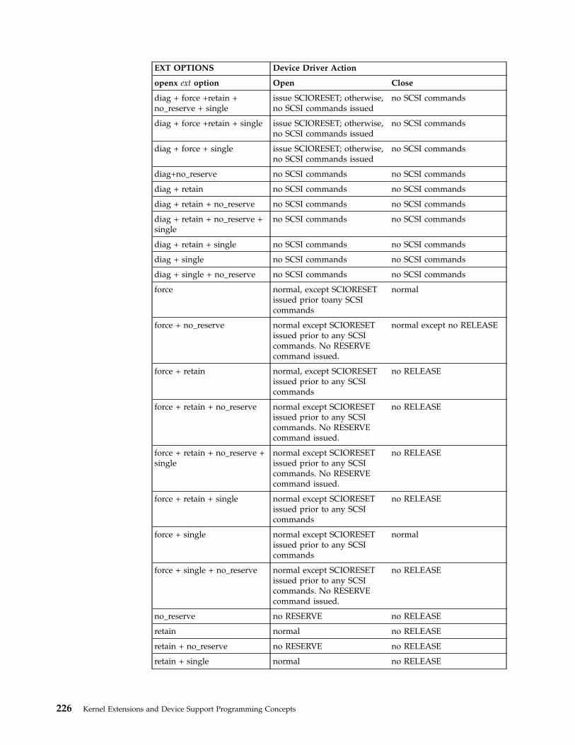
EXT OPTIONS Device Driver Action
openx ext option Open Close
diag + force +retain +no_reserve + single
issue SCIORESET; otherwise,no SCSI commands issued
no SCSI commands
diag + force +retain + single issue SCIORESET; otherwise,no SCSI commands issued
no SCSI commands
diag + force + single issue SCIORESET; otherwise,no SCSI commands issued
no SCSI commands
diag+no_reserve no SCSI commands no SCSI commands
diag + retain no SCSI commands no SCSI commands
diag + retain + no_reserve no SCSI commands no SCSI commands
diag + retain + no_reserve +single
no SCSI commands no SCSI commands
diag + retain + single no SCSI commands no SCSI commands
diag + single no SCSI commands no SCSI commands
diag + single + no_reserve no SCSI commands no SCSI commands
force normal, except SCIORESETissued prior toany SCSIcommands
normal
force + no_reserve normal except SCIORESETissued prior to any SCSIcommands. No RESERVEcommand issued.
normal except no RELEASE
force + retain normal, except SCIORESETissued prior to any SCSIcommands
no RELEASE
force + retain + no_reserve normal except SCIORESETissued prior to any SCSIcommands. No RESERVEcommand issued.
no RELEASE
force + retain + no_reserve +single
normal except SCIORESETissued prior to any SCSIcommands. No RESERVEcommand issued.
no RELEASE
force + retain + single normal except SCIORESETissued prior to any SCSIcommands
no RELEASE
force + single normal except SCIORESETissued prior to any SCSIcommands
normal
force + single + no_reserve normal except SCIORESETissued prior to any SCSIcommands. No RESERVEcommand issued.
no RELEASE
no_reserve no RESERVE no RELEASE
retain normal no RELEASE
retain + no_reserve no RESERVE no RELEASE
retain + single normal no RELEASE
226 Kernel Extensions and Device Support Programming Concepts

EXT OPTIONS Device Driver Action
openx ext option Open Close
retain + single + no_reserve normal except no RESERVEcommand issued
no RELEASE
single normal normal
single + no_reserve no RESERVE no RELEASE
Closing the SCSI Device
When a SCSI device driver is preparing to close a device through the SCSI adapterdevice driver, it must ensure that all transactions are complete. When the SCSIadapter device driver receives a SCIOSTOP ioctl operation and there are pendingI/O requests, the ioctl operation does not return until all have completed. Newrequests received during this time are rejected from the adapter device driver’sddstrategy routine.
When the SCSI adapter device driver receives an SCIOSTOPTGT ioctl operation,it must forcibly free any receive data buffers that have been queued to the SCSIdevice driver for this device and have not been returned to the SCSI adapterdevice driver through the buffer free routine. The SCSI device driver is responsiblefor making sure all the receive data buffers are freed before calling theSCIOSTOPTGT ioctl operation. However, the SCSI adapter device driver mustcheck that this is done, and, if necessary, forcibly free the buffers. The buffers mustbe freed because those not freed result in memory areas being permanently lost tothe system (until the next boot).
To allow the SCSI adapter device driver to free buffers that are sent to the SCSIdevice driver but never returned, it must track which tm_bufs are currentlyqueued to the SCSI device driver. Tracking tm_bufs requires the SCSI adapterdevice driver to violate the general SCSI rule, which states the SCSI adapter devicedriver should not modify the tm_bufs structure while it is queued to the SCSIdevice driver. This exception to the rule is necessary since it is never acceptable notto free memory allocated from the system.
SCSI Error Processing
It is the responsibility of the SCSI device driver to process SCSI check conditionsand other returned errors properly. The SCSI adapter device driver only passesSCSI commands without otherwise processing them and is not responsible fordevice error recovery.
Device Driver and Adapter Device Driver Interfaces
The SCSI device drivers can have both character (raw) and block special files in the/dev directory. The SCSI adapter device driver has only character (raw) special filesin the /dev directory and has only the ddconfig, ddopen, ddclose, dddump, andddioctl entry points available to operating system programs. The ddread andddwrite entry points are not implemented.
Internally, the devsw table has entry points for the ddconfig, ddopen, ddclose,dddump, ddioctl, and ddstrategy routines. The SCSI device drivers pass their SCSIcommands to the SCSI adapter device driver by calling the SCSI adapter device
Chapter 12. Small Computer System Interface Subsystem 227
driver ddstrategy routine. (This routine is unavailable to other operating systemprograms due to the lack of a block-device special file.)
Access to the SCSI adapter device driver’s ddconfig, ddopen, ddclose, dddump,ddioctl, and ddstrategy entry points by the SCSI device drivers is performedthrough the kernel services provided. These include such services as fp_opendev,fp_close, fp_ioctl, devdump, and devstrategy.
Performing SCSI Dumps
A SCSI adapter device driver must have a dddump entry point if it is used toaccess a system dump device. A SCSI device driver must have a dddump entrypoint if it drives a dump device. Examples of dump devices are disks and tapes.
Note: System services providing interrupt and timer services are unavailablefor use in the dump routine. Kernel DMA services are assumed to beavailable for use by the dump routine. The SCSI adapter device driver shouldbe designed to ignore extra DUMPINIT and DUMPSTART commands to thedddump entry point.
The DUMPQUERY option should return a minimum transfer size of 0 bytes, and amaximum transfer size equal to the maximum transfer size supported by the SCSIadapter device driver.
Calls to the SCSI adapter device driver DUMPWRITE option should use the argparameter as a pointer to the sc_buf structure to be processed. Using this interface,a SCSI write command can be executed on a previously started (opened) targetdevice. The uiop parameter is ignored by the SCSI adapter device driver during theDUMPWRITE command. Spanned, or consolidated, commands are not supportedusing the DUMPWRITE option. Gathered write commands are also not supportedusing the DUMPWRITE option. No queuing of sc_buf structures is supportedduring dump processing since the dump routine runs essentially as a subroutinecall from the caller’s dump routine. Control is returned when the entire sc_bufstructure has been processed.
Note: No error recovery is employed during a DUMPWRITE operationbecause any error that occurs durin gthe operation is a problem. Returnvalues from the call to the dddump routine indicate the specific nature of thefailure.
Successful completion of the selected operation is indicated by a 0 return value tothe subroutine. Unsuccessful completion is indicated by a return code set to one ofthe following values for the errno global variable. The various sc_buf status fields,including the b_error field, are not set by the SCSI adapter device driver atcompletion of the DUMPWRITE command. Error logging is, of necessity, notsupported during the dump.
v An errno value of EINVAL indicates that a request that was not valid passed tothe SCSI adapter device driver, such as to attempt a DUMPSTART commandbefore successfully executing a DUMPINIT command.
v An errno value of EIO indicates that the SCSI adapter device driver was unableto complete the command due to a lack of required resources or an I/O error.
v An errno value of ETIMEDOUT indicates that the adapter did not respond withcompletion status before the passed command time-out value expired.
228 Kernel Extensions and Device Support Programming Concepts

SCSI Target-Mode Overview
Note: This operation is not supported by all SCSI I/O controllers.
The SCSI target-mode interface is intended to be used with the SCSI initiator-modeinterface to provide the equivalent of a full-duplex communications path betweenprocessor type devices. Both communicating devices must support target-modeand initiator-mode. To work with the SCSI subsystem in this manner, an attacheddevice’s target-mode and initiator-mode interfaces must meet certain minimumrequirements:
v The device’s target-mode interface must be capable of receiving and processingat least the following SCSI commands:
– send
– request sense
– inquiry
The data returned by the inquiry command must set the peripheral device typefield to processor device. The device should support the vendor and productidentification fields. Additional functional SCSI requirements, such as SCSImessage support, must be addressed by examining the detailed functionalspecification of the SCSI initiator that the target-mode device is attached to.
v The attached device’s initiator mode interface must be capable of sending thefollowing SCSI commands:
– send
– request sense
In addition, the inquiry command should be supported by the attached initiatorif it needs to identify SCSI target devices. Additional functional SCSIrequirements, such as SCSI message support, must be addressed by examiningthe detailed functional specification of the SCSI target that the initiator-modedevice is attached to.
Configuring and Using SCSI Target Mode
The adapter, acting as either a target or initiator device, requires its own SCSI ID.This ID, as well as the IDs of all attached devices on this SCSI bus, must be uniqueand between 0 and 7, inclusive. Since each device on the bus must be at a uniqueID, the user must complete any installation and configuration of the SCSI devicesrequired to set the correct IDs before physically cabling the devices together.Failure to do so will produce unpredictable results.
SCSI target mode in the SCSI subsystem does not attempt to implement anyreceive-data protocol, with the exception of actions taken to prevent an applicationfrom excessive receive-data-buffer usage. Any protocol required to maintain orotherwise manage the communications of data must be implemented inuser-supplied programs. The only delays in receiving data are those inherent in theSCSI subsystem and the hardware environment in which it operates.
The SCSI target mode is capable of simultaneously receiving data from all attachedSCSI IDs using SCSI send commands. In target-mode, the host adapter is assumedto act as a single SCSI Logical Unit Number (LUN) at its assigned SCSI ID.Therefore, only one logical connection is possible between each attached SCSI
Chapter 12. Small Computer System Interface Subsystem 229

initiator on the SCSI Bus and the host adapter. The SCSI subsystem is designed tobe fully capable of simultaneously sending SCSI commands in initiator-mode whilereceiving data in target-mode.
Managing Receive-Data BuffersIn the SCSI subsystem target-mode interface, the SCSI adapter device driver isresponsible for managing the receive-data buffers versus the SCSI device driverbecause the buffering is dependent upon how the adapter works. It is not possiblefor the SCSI device driver to run a single approach that is capable of making fulluse of the performance advantages of various adapter’s buffering schemes. Withthe SCSI adapter device driver layer performing the buffer management, the SCSIdevice driver can be interfaced to a variety of adapter types and can potentially getthe best possible performance out of each adapter. This approach also allowsmultiple SCSI target-mode device drivers to be run on top of adapters that use ashared-pool buffer management scheme. This would not be possible if thetarget-mode device drivers managed the buffers.
Understanding Target-Mode Data PacingBecause it is possible for the attached initiator device to send data faster than thehost operating system and associated application can process it, eventually thesituation arises in which all buffers for this device instance are in use at the sametime. There are two possible scenarios:
v The previous send command has been received by the adapter, but there is nospace for the next send command.
v The send command is not yet completed, and there is no space for theremaining data.
In both cases, the combination of the SCSI adapter device driver and the SCSIadapter must be capable of stopping the flow of data from the initiator device.
SCSI Adapter Device DriverThe adapter can handle both cases described previously by simply accepting thesend command (if newly received) and then disconnecting during the data phase.When buffer space becomes available, the SCSI adapter reconnects and continuesthe data transfer. As an alternative, when handling a newly received command, acheck condition can be given back to the initiator to indicate a lack of resources.The implementation of this alternative is adapter-dependent. The technique ofaccepting the command and then disconnecting until buffer space is availableshould result in better throughput, as it avoids both a request sense command andthe retry of the send command.
For adapters allowing a shared pool of buffers to be used for all attached initiators’data transfers, an additional problem can result. If any single initiator instance isallowed to transfer data continually, the entire shared pool of buffers can fill up.These filled-up buffers prevent other initiator instances from transferring data. Tosolve this problem, the combination of the SCSI adapter device driver and the hostSCSI adapter must stop the flow of data from a particular initiator ID on the bus.This could include disconnecting during the data phase for a particular ID butallowing other IDs to continue data transfer. This could begin when the number oftm_buf structures on a target-mode instance’s tm_buf queue equals the number ofbuffers allocated for this device. When a threshold percentage of the number ofbuffers is processed and returned to the SCSI adapter device driver’s buffer-freeroutine, the ID can be enabled again for the continuation of data transfer.
230 Kernel Extensions and Device Support Programming Concepts

SCSI Device DriverThe SCSI device driver can optionally be informed by the SCSI adapter devicedriver whenever all buffers for this device are in use. This is known as amaximum-buffer-usage event. To pass this information, the SCSI device drivermust be registered for notification of asynchronous event status from the SCSIadapter device driver. Registration is done by calling the SCSI adapterdevice-driver ioctl entry point with the SCIOEVENT operation. If registering forevent notification, the SCSI device driver receives notification of all asynchronousevents, not just the maximum buffer usage event.
Understanding the SCSI Target Mode Device Driver ReceiveBuffer Routine
The SCSI target-mode device-driver receive buffer routine must be a pinnedroutine that the SCSI adapter device driver can directly address. This routine iscalled directly from the SCSI adapter device driver hardware interrupt handlingroutine. The SCSI device driver writer must be aware of how this routine affectsthe design of the SCSI device driver.
First, since the receive buffer routine is running on the hardware interrupt level,the SCSI device driver must limit operations in order to limit routine processingtime. In particular, the data copy, which occurs because the data is queued aheadof the user read request, must not occur in the receive buffer routine. Datacopying in this routine will adversely affect system response time. Data copy isbest performed in a process level SCSI device-driver routine. This routine sleeps,waiting for data, and is awakened by the receive buffer routine. Typically, thisprocess level routine is the SCSI device driver’s read routine.
Second, the receive buffer routine is called at the SCSI adapter device driverhardware interrupt level, so care must be taken when disabling interrupts. Theymust be disabled to the correct level in places in the SCSI device driver’s lowerexecution priority routines which manipulate variables also modified in the receivebuffer routine. To allow the SCSI device driver to disable to the correct level, theSCSI adapter device-driver writer must provide a configuration database attribute,named intr_priority, that defines the interrupt class, or priority, the adapter runson. The SCSI device-driver configuration method should pass this attribute to theSCSI device driver along with other configuration data for the device instance.
Third, the SCSI device-driver writer must follow any other general system rules forwriting a routine that must execute in an interrupt environment. For example, theroutine must not attempt to sleep or wait on I/O operations. It can performwake-up calls to allow the process level to handle those operations.
Duties of the SCSI device driver receive buffer routine include:
v Matching the data with the appropriate target-mode instance.
v Queuing the tm_buf structures to the appropriate target-mode instance.
v Waking up the process-level routine for further processing of the received data.
After the tm_buf structure has been passed to the SCSI device driver receivebuffer routine, the SCSI device driver is considered to be responsible for it.Responsibilities include processing the data and any error conditions and alsomaintaining the next pointer for chained tm_buf structures. The SCSI devicedriver’s responsibilities for the tm_buf structures end when it passes the structureback to the SCSI adapter device driver.
Chapter 12. Small Computer System Interface Subsystem 231

Until the tm_buf structure is again passed to the SCSI device driver receive bufferroutine, the SCSI adapter device driver is considered responsible for it. The SCSIadapter device-driver writer must be aware that during the time the SCSI devicedriver is responsible for the tm_buf structure, it is still possible for the SCSIadapter device driver to access the structure’s contents. Access is possible becauseonly one copy of the structure is in memory, and only a pointer to the structure ispassed to the SCSI device driver.
Note: Under no circumstances should the SCSI adapter device driver accessthe structure or modify its contents while the SCSI device driver isresponsible for it, or the other way around.
It is recommended that the SCSI device-driver writer implement a threshold levelto wake up the process level with available tm_buf structures. This way,processing for some of the buffers, including copying the data to the user buffer,can be overlapped with time spent waiting for more data. It is also recommendedthe writer implement a threshold level for these buffers to handle cases where thesend command data length exceeds the aggregate receive-data buffer space. Asuggested threshold level is 25% of the device’s total buffers. That is, when 25% ormore of the number of buffers allocated for this device is queued and no end tothe send command is encountered, the SCSI device driver receive buffer routineshould wake the process level to process these buffers.
Understanding the tm_buf Structure
The tm_buf structure is used for communication between the SCSI device driverand the SCSI adapter device driver for a target-mode received-data buffer. Thetm_buf structure is passed by pointer directly to routines whose entry points havebeen registered through the SCIOSTARTTGT ioctl operation of the SCSI adapterdevice driver. The SCSI device driver is required to call this ioctl operation whenopening a target-mode device instance.
Fields in the tm_buf StructureThe tm_buf structure contains certain fields used to pass a received data bufferfrom the SCSI adapter device driver to the SCSI device driver. Other fields areused to pass returned status back to the SCSI device driver. After processing thedata, the tm_buf structure is passed back from the SCSI device driver to the SCSIadapter device driver to allow the buffer to be reused. The tm_buf structure isdefined in the /usr/include/sys/scsi.h file and contains the following fields:
Note: Reserved fields must not be modified by the SCSI device driver, unlessnoted otherwise. Nonreserved fields can be modified, except where notedotherwise.
1. The tm_correlator field is an optional field for the SCSI device driver. Thisfield is a copy of the field with the same name that was passed by the SCSIdevice driver in the SCIOSTARTTGT ioctl. The SCSI device driver should usethis field to speed the search for the target-mode device instance the tm_bufstructure is associated with. Alternatively, the SCSI device driver can combinethe tm_buf.user_id and tm_buf.adap_devno fields to find the associated device.
2. The adap_devno field is the device major and minor numbers of the adapterinstance on which this target mode device is defined. This field may be used tofind the particular target-mode instance the tm_buf structure is associated with.
Note: The SCSI device driver must not modify this field.
232 Kernel Extensions and Device Support Programming Concepts
3. The data_addr field is the kernel space address where the data begins for thisbuffer.
4. The data_len field is the length of valid data in the buffer starting at thetm_buf.data_addr location in memory.
5. The user_flag field is a set of bit flags that can be set to communicateinformation about this data buffer to the SCSI device driver. Except wherenoted, one or more of the following flags can be set:
TM_HASDATA Set to indicate a valid tm_buf structure
TM_MORE_DATA Set if more data is coming (that is, more tm_buf structures) for aparticular send command. This is only possible for adapters thatsupport spanning the send command data across multiple receivebuffers. This flag cannot be used with the TM_ERROR flag.
TM_ERROR Set if any error occurred on a particular send command. This flagcannot be used with the TM_MORE_DATA flag.
6. The user_id field is set to the SCSI ID of the initiator that sent the data to thistarget mode instance. If more than one adapter is used for target mode in thissystem, this ID may not be unique. Therefore, this field must be used incombination with the tm_buf.adap_devno field to find the target-mode instancethis ID is associated with.
Note: The SCSI device driver must not modify this field.
7. The status_validity field contains the following bit flag:
SC_ADAPTER_ERROR Indicates the tm_buf.general_card_status is valid.
8. The general_card_status field is a returned status field that gives a broadindication of the class of error encountered by the adapter. This field is validwhen its status-validity bit is set in the tm_buf.status_validity field. Thedefinition of this field is the same as that found in the structure definition (see“Understanding the sc_buf Structure” on page 218), except theSC_CMD_TIMEOUT value is not possible and is never returned for atarget-mode transfer.
9. The next field is a tm_buf pointer that is either null, meaning this is the onlyor last tm_buf structure, or else contains a non-null pointer to the next tm_bufstructure.
Understanding the Execution of SCSI Target-Mode Requests
The target-mode interface provided by the SCSI subsystem is designed to handledata reception from SCSI send commands. The host SCSI adapter acts as asecondary device that waits for an attached initiator device to issue a SCSI sendcommand. The SCSI send command data is received by buffers managed by theSCSI adapter device driver. The tm_buf structure is used to manage individualbuffers. For each buffer of data received from an attached initiator, the SCSIadapter device driver passes a tm_buf structure to the SCSI device driver forprocessing. Multiple tm_buf structures can be linked together and passed to theSCSI device driver at one time. When the SCSI device driver has processed one ormore tm_buf structures, it passes the tm_buf structures back to the SCSI adapterdevice driver so they can be reused.
Detailed Execution of Target-Mode RequestsWhen a send command is received by the host SCSI adapter, data is placed in oneor more receive-data buffers. These buffers are made available to the adapter bythe SCSI adapter device driver. The procedure by which the data gets from the
Chapter 12. Small Computer System Interface Subsystem 233

SCSI bus to the system-memory buffer is adapter-dependent. The SCSI adapterdevice driver takes the received data and updates the information in one or moretm_buf structures in order to identify the data to the SCSI device driver. Thisprocess includes filling the tm_correlator, adap_devno, data_addr, data_len,user_flag, and user_id fields. Error status information is put in thestatus_validity and general_card_status fields. The next field is set to null toindicate this is the only element, or set to non-null to link multiple tm_bufstructures. If there are multiple tm_buf structures, the final tm_buf.next field is setto null to terminate the chain. If there are multiple tm_buf structures and they arelinked, they must all be from the same initiator SCSI ID. Thetm_buf.tm_correlator field, in this case, has the same value as it does in theSCIOSTARTTGT ioctl operation to the SCSI adapter device driver. The SCSIdevice driver should use this field to speed the search for the target-mode instancedesignated by this tm_buf structure. For example, when using the value oftm_buf.tm_correlator as a pointer to the device-information structure associatedwith this target-mode instance.
Each send command, no matter how short its data length, requires its own tm_bufstructure. For host SCSI adapters capable of spanning multiple receive-data bufferswith data from a single send command, the SCSI adapter device driver must setthe TM_MORE_DATA flag in the tm_buf.user_flag fields of all but the finaltm_buf structure holding data for the send command. The SCSI device drivermust be designed to support the TM_MORE_DATA flag. Using this flag, thetarget-mode SCSI device driver can associate multiple buffers with the singletransfer they represent. The end of a send command will be the boundary used bythe SCSI device driver to satisfy a user read request.
The SCSI adapter device driver is responsible for sending the tm_buf structures fora particular initiator SCSI ID to the SCSI device driver in the order they werereceived. The SCSI device driver is responsible for processing these tm_bufstructures in the order they were received. There is no particular ordering impliedin the processing of simultaneous send commands from different SCSI IDs, as longas the data from an individual SCSI ID’s send command is processed in the orderit was received.
The pointer to the tm_buf structure chain is passed by the SCSI adapter devicedriver to the SCSI device driver’s receive buffer routine. The address of this routineis registered with the SCSI adapter device driver by the SCSI device driver usingthe SCIOSTARTTGT ioctl. The duties of the receive buffer routine includequeuing the tm_buf structures and waking up a process-level routine (typically theSCSI device driver’s read routine) to process the received data.
When the process-level SCSI device driver routine finishes processing one or moretm_buf structures, it passes them to the SCSI adapter device driver’s buffer-freeroutine. The address of this routine is registered with the SCSI device driver in anoutput field in the structure passed to the SCSI adapter device driverSCIOSTARTTGT ioctl operation. The buffer-free routine must be a pinned routinethe SCSI device driver can directly access. The buffer-free routine is typically calleddirectly from the SCSI device driver buffer-handling routine. The SCSI devicedriver chains one or more tm_buf structures by using the next field (a null valuefor the last tm_buf next field ends the chain). It then passes a pointer, which pointsto the head of the chain, to the SCSI adapter device driver buffer-free routine.These tm_buf structures must all be for the same target-mode instance. Also, theSCSI device driver must not modify the tm_buf.user_id or tm_buf.adap_devnofield.
234 Kernel Extensions and Device Support Programming Concepts
The SCSI adapter device driver takes the tm_buf structures passed to its buffer-freeroutine and attempts to make the described receive buffers available to the adapterfor future data transfers. Since it is desirable to keep as many buffers as possibleavailable to the adapter, the SCSI device driver should pass processed tm_bufstructures to the SCSI-adapter device driver’s buffer-free routine as quickly aspossible. The writer of a SCSI device driver should avoid requiring the last bufferof a send command to be received before processing buffers, as this could cause asituation where all buffers are in use and the send command has not completed. Itis recommended that the writer therefore place a threshold of 25% on the freebuffers. That is, when 25% or more of the number of buffers allocated for thisdevice have been processed and the send command is not completed, the SCSIdevice driver should free the processed buffers by passing them to the SCSIadapter device driver’s buffer-free routine.
Required SCSI Adapter Device Driver ioctl Commands
Various ioctl operations must be performed for proper operation of the SCSIadapter device driver. The ioctl operations described here are the minimum set ofcommands the SCSI adapter device driver must implement to support SCSI devicedrivers. Other operations may be required in the SCSI adapter device driver tosupport, for example, system management facilities and diagnostics. SCSI devicedriver writers also need to understand these ioctl operations.
Every SCSI adapter device driver must support the IOCINFO ioctl operation. Thestructure to be returned to the caller is the devinfo structure, including the scsiunion definition for the SCSI adapter, which can be found in the/usr/include/sys/devinfo.h file. The SCSI device driver should request theIOCINFO ioctl operation (probably during its open routine) to get the maximumtransfer size of the adapter.
Note: The SCSI adapter device driver ioctl operations can only be called fromthe process level. They cannot be executed from a call on any more favoredpriority levels. Attempting to call them from a more favored priority level canresult in a system crash.
Initiator-Mode ioctl Commands
The following SCIOSTART and SCIOSTOP operations must be sent by the SCSIdevice driver (for the open and close routines, respectively) for each device. Theycause the SCSI adapter device driver to allocate and initialize internal resources.The SCIOHALT ioctl operation is used to abort pending or running commands,usually after signal processing by the SCSI device driver. This might be used by aSCSI device driver to end an operation instead of waiting for completion or a timeout. The SCIORESET operation is provided for clearing device hard errors andcompeting initiator reservations during open processing by the SCSI device driver.The SCIOGTHW operation is supported by SCSI adapter device drivers thatsupport gathered write commands to target devices.
Except where noted otherwise, the arg parameter for each of the ioctl operationsdescribed here must contain a long integer. In this field, the least significant byte isthe SCSI LUN and the next least significant byte is the SCSI ID value. (The uppertwo bytes are reserved and should be set to 0.) This provides the informationrequired to allocate or deallocate resources and perform SCSI bus operations forthe ioctl operation requested.
Chapter 12. Small Computer System Interface Subsystem 235

The following information is provided on the various ioctl operations:
SCIOSTART This operation allocates and initializes SCSI device-dependent informationlocal to the SCSI adapter device driver. Run this operation only on the firstopen of an ID/LUN device. Subsequent SCIOSTART commands to the sameID/LUN fail unless an intervening SCIOSTOP command is issued.
The following values for the errno global variable are supported:
0 Indicates successful completion.
EIO Indicates lack of resources or other error-preventing deviceallocation.
EINVALIndicates that the selected SCSI ID and LUN are already in use, orthe SCSI ID matches the adapter ID.
ETIMEDOUTIndicates that the command did not complete.
SCIOSTOP This operation deallocates resources local to the SCSI adapter device driverfor this SCSI device. This should be run on the last close of an ID/LUNdevice. If an SCIOSTART operation has not been previously issued, thiscommand is unsuccessful.
The following values for the errno global variable should be supported:
0 Indicates successful completion.
EIO Indicates error preventing device deallocation.
EINVALIndicates that the selected SCSI ID and LUN have not been started.
ETIMEDOUTIndicates that the command did not complete.
SCIOHALT This operation halts outstanding transactions to this ID/LUN device andcauses the SCSI adapter device driver to stop accepting transactions for thisdevice. This situation remains in effect until the SCSI device driver sendsanother transaction with the SC_RESUME flag set (in the sc_buf.flags field)for this ID/LUN combination. The SCIOHALT ioctl operation causes theSCSI adapter device driver to fail the command in progress, if any, as well asall queued commands for the device with a return value of ENXIO in thesc_buf.bufstruct.b_error field. If an SCIOSTART operation has not beenpreviously issued, this command fails.
The following values for the errno global variable are supported:
0 Indicates successful completion.
EIO Indicates an unrecovered I/O error occurred.
EINVALIndicates that the selected SCSI ID and LUN have not been started.
ETIMEDOUTIndicates that the command did not complete.
236 Kernel Extensions and Device Support Programming Concepts
SCIORESET This operation causes the SCSI adapter device driver to send a SCSI BusDevice Reset (BDR) message to the selected SCSI ID. For this operation, theSCSI device driver should set the LUN in the arg parameter to the LUN IDof a LUN on this SCSI ID, which has been successfully started using theSCIOSTART operation.
The SCSI device driver should use this command only when directed to do aforced open. This occurs in two possible situations: one, when it is desirable toforce the device to drop a SCSI reservation; two, when the device needs to bereset to clear an error condition (for example, when running diagnostics onthis device).
Note: In normal system operation, this command should not be issued,as it would force the device to drop a SCSI reservation another initiator(and, hence, another system) may have. If an SCIOSTART operationhas not been previously issued, this command is unsuccessful.
The following values for the errno global variable are supported:
0 Indicates successful completion.
EIO Indicates an unrecovered I/O error occurred.
EINVALIndicates that the selected SCSI ID and LUN have not been started.
ETIMEDOUTIndicates that the command did not complete.
SCIOGTHW This operation is only supported by SCSI adapter device drivers that supportgathered write commands. The purpose of the operation is to indicatesupport for gathered writes to SCSI device drivers that intend to use thisfacility. If the SCSI adapter device driver does not support gathered writecommands, it must fail the operation. The SCSI device driver should call thisoperation from its open routine for a particular device instance. If theoperation is unsuccessful, the SCSI device driver should not attempt to run agathered write command.
The arg parameter to the SCIOGTHW is set to null by the caller to indicatethat no input parameter is passed:
The following values for the errno global variable are supported:
0 Indicates successful completion and in particular that the adapterdriver supports gathered writes.
EINVALIndicates that the SCSI adapter device driver does not supportgathered writes.
Target-Mode ioctl Commands
The following SCIOSTARTTGT and SCIOSTOPTGT operations must be sent bythe SCSI device driver (for the open and close routines, respectively) for eachtarget-mode device instance. This causes the SCSI adapter device driver to allocateand initialize internal resources, and, if necessary, prepare the hardware foroperation.
Target-mode support in the SCSI device driver and SCSI adapter device driver isoptional. A failing return code from these commands, in the absence of any
Chapter 12. Small Computer System Interface Subsystem 237

programming error, indicates target mode is not supported. If the SCSI devicedriver requires target mode, it must check the return code to verify the SCSIadapter device driver supports it.
Only a kernel process or device driver can call these ioctls. If attempted by a userprocess, the ioctl will fail, and the errno global variable will be set to EPERM.
The following information is provided on the various target-mode ioctl operations:
SCIOSTARTTGTThis operation opens a logical path to a SCSI initiator device. It allocatesand initializes SCSI device-dependent information local to the SCSI adapterdevice driver. This is run by the SCSI device driver in its open routine.Subsequent SCIOSTARTTGT commands to the same ID (LUN is always0) are unsuccessful unless an intervening SCIOSTOPTGT is issued. Thiscommand also causes the SCSI adapter device driver to allocate systembuffer areas to hold data received from the initiator, and makes the adapterready to receive data from the selected initiator.
The arg parameter to the SCIOSTARTTGT should be set to the address ofan sc_strt_tgt structure, which is defined in the /usr/include/sys/scsi.h file.The following parameters are supported:
id The caller fills in the SCSI ID of the attached SCSI initiator.
lun The caller sets the LUN to 0, as the initiator LUN is ignored forreceived data.
buf_sizeThe caller specifies size in bytes to be used for each receive bufferallocated for this host target instance.
num_bufsThe caller specifies how many buffers to allocate for this targetinstance.
tm_correlatorThe caller optionally places a value in this field to be passed backin each tm_buf for this target instance.
recv_funcThe caller places in this field the address of a pinned routine theSCSI adapter device driver should call to pass tm_bufs receivedfor this target instance.
free_funcThis is an output parameter the SCSI adapter device driver fillswith the address of a pinned routine which the SCSI device drivercalls to pass tm_bufs after they have been processed. The SCSIadapter device driver ignores the value passed as input.
Note: All reserved fields should be set to 0 by the caller.
The following values for the errno global variable are supported:
0 Indicates successful completion.
EINVALAn SCIOSTARTTGT command has already been issued to thisSCSI ID.
238 Kernel Extensions and Device Support Programming Concepts

The passed SCSI ID is the same as that of the adapter.
The LUN ID field is not set to zero.
The buf_size is not valid. This is an adapter dependent value.
The num_bufs is not valid. This is an adapter dependent value.
The recv_func value, which cannot be null, is not valid.
EPERMIndicates the caller is not running in kernel mode, which is theonly mode allowed to execute this operation.
ENOMEMIndicates that a memory allocation failure has occurred.
EIO Indicates an I/O error occurred, preventing the device driver fromcompleting SCIOSTARTTGT processing.
SCIOSTOPTGTThis operation closes a logical path to a SCSI initiator device. It causes theSCSI adapter device driver to deallocate device dependent informationareas allocated in response to a SCIOSTARTTGT operation. It also causesthe SCSI adapter device driver to deallocate system buffer areas used tohold data received from the initiator, and to disable the host adapter’sability to receive data from the selected initiator.
The arg parameter to the SCIOSTOPTGT ioctl should be set to the addressof an sc_stop_tgt structure, which is defined in the /usr/include/sys/scsi.hfile. The caller fills in the id field with the SCSI ID of the SCSI initiator,and sets the lun field to 0 as the initiator LUN is ignored for received data.Reserved fields should be set to 0 by the caller.
The following values for the errno global variable should be supported:
0 Indicates successful completion.
EINVALAn SCIOSTARTTGT command has not been previously issued tothis SCSI ID.
EPERMIndicates the caller is not running in kernel mode, which is theonly mode allowed to execute this operation.
Target- and Initiator-Mode ioctl Commands
For either target or initiator mode, the SCSI device driver may issue anSCIOEVENT ioctl operation to register for receiving asynchronous event statusfrom the SCSI adapter device driver for a particular device instance. This is anoptional call for the SCSI device driver, and is optionally supported for the SCSIadapter device driver. A failing return code from this command, in the absence ofany programming error, indicates it is not supported. If the SCSI device driverrequires this function, it must check the return code to verify the SCSI adapterdevice driver supports it.
Only a kernel process or device driver can invoke these ioctls. If attempted by auser process, the ioctl will fail, and the errno global variable will be set to EPERM.
Chapter 12. Small Computer System Interface Subsystem 239
The event registration performed by this ioctl operation is allowed once per devicesession. Only the first SCIOEVENT ioctl operation is accepted after the devicesession is opened. Succeeding SCIOEVENT ioctl operations will fail, and the errnoglobal variable will be set to EINVAL. The event registration is canceledautomatically when the device session is closed.
The arg parameter to the SCIOEVENT ioctl operation should be set to the addressof an sc_event_struct structure, which is defined in the /usr/include/sys/scsi.h file.The following parameters are supported:
id The caller sets id to the SCSI ID of the attached SCSI target devicefor initiator-mode. For target-mode, the caller sets the id to theSCSI ID of the attached SCSI initiator device.
lun The caller sets the lun field to the SCSI LUN of the attached SCSItarget device for initiator-mode. For target-mode, the caller setsthe lun field to 0.
mode Identifies whether the initiator- or target-mode device is beingregistered. These values are possible:
SC_IM_MODEThis is an initiator mode device.
SC_TM_MODEThis is a target mode device.
async_correlator The caller places a value in this optional field which is saved bythe SCSI adapter device driver and returned when an event occursin this field in the sc_event_info structure. This structure isdefined in the /user/include/sys/scsi.h file.
async_func The caller fills in the address of a pinned routine which the SCSIadapter device driver calls whenever asynchronous event status isavailable. The SCSI adapter device driver passes a pointer to asc_event_info structure to the caller’s async_func routine.
Note: All reserved fields should be set to 0 by the caller.
The following values for the errno global variable are supported:
0 Indicates successful completion.
EINVAL Either an SCIOSTART or SCIOSTARTTGT has not been issued to this deviceinstance, or this device is already registered for async events.
EPERM Indicates the caller is not running in kernel mode, which is the only modeallowed to execute this operation.
240 Kernel Extensions and Device Support Programming Concepts
Chapter 13. Fibre Channel Protocol for SCSI Subsystem
This overview describes the interface between a Fibre Channel Protocol for SCSI(FCP) device driver and a FCP adapter device driver. The term FC SCSI is alsoused to refer to FCP devices. It is directed toward those wishing to design andwrite a FCP device driver that interfaces with an existing FCP adapter devicedriver. It is also meant for those wishing to design and write a FCP adapter devicedriver that interfaces with existing FCP device drivers.
FCP Subsystem Overview
The main topics covered in this overview are:
v “Responsibilities of the FCP Adapter Device Driver”
v “Responsibilities of the FCP Device Driver”
v “Communication between FCP Devices” on page 242
v “Initiator-Mode Support” on page 242
This section frequently refers to both a FCP device driver and a FCP adapterdevice driver. These two distinct device drivers work together in a layeredapproach to support attachment of a range of FCP devices. The FCP adapter devicedriver is the lower device driver of the pair, and the FCP device driver is the upperdevice driver.
Responsibilities of the FCP Adapter Device DriverThe FCP adapter device driver (the lower layer) is the software interface to thesystem hardware. This hardware includes the FCP transport layer hardware plusany other system I/O hardware required to run an I/O request. The FCP adapterdevice driver hides the details of the I/O hardware from the FCP device driver.The design of the software interface allows a user with limited knowledge of thesystem hardware to write the upper device driver.
The FCP adapter device driver manages the FCP transport layer but not the FCPdevices. It can send and receive FCP commands, but it cannot interpret thecontents of the command. The lower driver also provides recovery and logging forerrors related to the FCP transport layer and system I/O hardware. Managementof the device specifics is left to the FCP device driver. The interface of the twodrivers allows the upper driver to communicate with different FCP transport layeradapters without requiring special code paths for each adapter.
Responsibilities of the FCP Device DriverThe FCP device driver (the upper layer) provides the rest of the operating systemwith the software interface to a given FCP device or device class. The upper layerrecognizes which FCP commands are required to control a particular FCP device ordevice class. The FCP device driver builds I/O requests containing device FCPcommands and sends them to the FCP adapter device driver in the sequenceneeded to operate the device successfully. The FCP device driver cannot manageadapter resources or give the FCP command to the adapter. Specifics about theadapter and system hardware are left to the lower layer.
The FCP device driver also provides recovery and logging for errors related to theFCP device it controls.
© Copyright IBM Corp. 1997, 1999 241

The operating system provides several kernel services allowing the FCP devicedriver to communicate with FCP adapter device driver entry points withouthaving the actual name or address of those entry points. The description containedin Logical File System Kernel Services can provide more information.
Communication between FCP DevicesWhen two FCP devices communicate, one assumes the initiator-mode role, and theother assumes the target-mode role. The initiator-mode device generates the FCPcommand, which requests an operation, and the target-mode device receives theFCP command and acts. It is possible for a FCP device to perform both rolessimultaneously.
When writing a new FCP adapter device driver, the writer must know which modeor modes must be supported to meet the requirements of the FCP adapter and anyinterfaced FCP device drivers.
Initiator-Mode SupportThe interface between the FCP device driver and the FCP adapter device driver forinitiator-mode support (that is, the attached device acts as a target) is accessedthrough calls to the FCP adapter device driver open (“open” on page 276), close(“close” on page 276), ioctl (“ioctl” on page 277), and strategy (“strategy” onpage 277) routines. I/O requests are queued to the FCP adapter device driverthrough calls to its strategy entry point.
Communication between the FCP device driver and the FCP adapter device driverfor a particular initiator I/O request is made through the scsi_buf structure, whichis passed to and from the strategy routine in the same way a standard driver usesa struct buf structure.
Understanding FCP Asynchronous Event Handling
Note: This operation is not supported by all FCP I/O controllers.
A FCP device driver can register a particular device instance for receivingasynchronous event status by calling the SCIOLEVENT ioctl operation for theFCP-adapter device driver (see “SCIOLEVENT” on page 266). When an eventcovered by the SCIOLEVENT ioctl operation is detected by the FCP adapterdevice driver, it builds an scsi_event_info structure and passes a pointer to thestructure and to the asynchronous event-handler routine entry point, which waspreviously registered. The fields in the structure are filled in by the FCP adapterdevice driver as follows:
scsi_idFor initiator mode, this is set to the SCSI ID of the attached FCP targetdevice. For target mode, this is set to the SCSI ID of the attached FCPinitiator device.
lun_id For initiator mode, this is set to the SCSI LUN of the attached FCP targetdevice. For target mode, this is set to 0).
mode Identifies whether the initiator or target mode device is being reported.The following values are possible:
SCSI_IM_MODE
An initiator mode device is being reported.
242 Kernel Extensions and Device Support Programming Concepts
SCSI_TM_MODE
A target mode device is being reported.
events This field is set to indicate what event or events are being reported. Thefollowing values are possible, as defined in the /usr/include/sys/scsi.h file:
SCSI_FATAL_HDW_ERR
A fatal adapter hardware error occurred.
SCSI_ADAP_CMD_FAILED
An unrecoverable adapter command failure occurred.
SCSI_RESET_EVENT
A FCP transport layer reset was detected.
SCSI_BUFS_EXHAUSTED
In target-mode, a maximum buffer usage event has occurred.
adap_devnoThis field is set to indicate the device major and minor numbers of theadapter on which the device is located.
async_correlatorThis field is set to the value passed to the FCP adapter device driver in thescsi_event_struct structure. The FCP device driver may optionally use thisfield to provide an efficient means of associating event status with thedevice instance it goes with. Alternatively, the FCP device driver woulduse the combination of the id, lun, mode, and adap_devno fields toidentify the device instance.
The information reported in the scsi_event_info.events field does not queue to theFCP device driver, but is instead reported as one or more flags as they occur. Sincethe data does not queue, the FCP adapter device driver writer can use a singlescsi_event_info structure and pass it one at a time, by pointer, to eachasynchronous event handler routine for the appropriate device instance. Afterdetermining for which device the events are being reported, the FCP device drivermust copy the scsi_event_info.events field into local space and must not modifythe contents of the rest of the scsi_event_info structure.
Since the event status is optional, the FCP device driver writer determines whataction is necessary to take upon receiving event status. The writer may decide tosave the status and report it back to the calling application, or the FCP devicedriver or application level program can take error recovery actions.
Defined Events and Recovery ActionsThe adapter fatal hardware failure event is intended to indicate that no furthercommands to or from this FCP device are likely to succeed, since the adapter it isattached to has failed. It is recommended that the application end the session withthe device.
The unrecoverable adapter command failure event is not necessarily a fatalcondition, but it can indicate that the adapter is not functioning properly. Possibleactions by the application program include:
v Ending of the session with the device in the near future.
v Ending of the session after multiple (two or more) such events.
v Attempt to continue the session indefinitely.
The SCSI Reset detection event is mainly intended as information only, but may beused by the application to perform further actions, if necessary.
Chapter 13. Fibre Channel Protocol for SCSI Subsystem 243

The maximum buffer usage detected event only applies to a given target-modedevice; it will not be reported for an initiator-mode device. This event indicates tothe application that this particular target-mode device instance has filled itsmaximum allotted buffer space. The application should perform read system callsfast enough to prevent this condition. If this event occurs, data is not lost, but it isdelayed to prevent further buffer usage. Data reception will be restored when theapplication empties enough buffers to continue reasonable operations. Thenum_bufs attribute may need to be increased to help minimize this problem. Also,it is possible that regardless of the number of buffers, the application simply is notprocessing received data fast enough. This may require some fine tuning of theapplication’s data processing routines.
Asynchronous Event-Handling RoutineThe FCP-device driver asynchronous event-handling routine is typically calleddirectly from the hardware interrupt-handling routine for the FCP adapter devicedriver. The FCP device driver writer must be aware of how this affects the designof the FCP device driver.
Since the event handling routine is running on the hardware interrupt level, theFCP device driver must be careful to limit operations in that routine. Processingshould be kept to a minimum. In particular, if any error recovery actions areperformed, it is recommended that the event-handling routine set state or statusflags only and allow a process level routine to perform the actual operations.
The FCP device driver must be careful to disable interrupts at the correct level inplaces where the FCP device driver’s lower execution priority routines manipulatevariables that are also modified by the event-handling routine. To allow the FCPdevice driver to disable at the correct level, the FCP adapter device driver writermust provide a configuration database attribute that defines the interrupt class, orpriority, it runs on. This attribute must be named intr_priority so that the FCPdevice driver configuration method knows which attribute of the parent adapter toquery. The FCP device driver configuration method should then pass this interruptpriority value to the FCP device driver along with other configuration data for thedevice instance.
The FCP device driver writer must follow any other general system rules forwriting a routine which must execute in an interrupt environment. For example,the routine must not attempt to sleep or wait on I/O operations. It can performwakeups to allow the process level to handle those operations.
Since the FCP device driver copies the information from the scsi_event_info.eventsfield on each call to its asynchronous event-handling routine, there is no resourceto free or any information which must be passed back later to the FCP adapterdevice driver.
FCP Error Recovery
If the device is in initiator mode, the error-recovery process varies depending onwhether or not the device is supporting command queuing. Also some devicesmay support NACA=1 error recovery. Thus FCP error recovery needs to deal withthe two following concepts.
244 Kernel Extensions and Device Support Programming Concepts

autosense dataWhen an FCP device returns a check condition or command terminated (thescsi_buf.scsi_status will have the value of SC_CHECK_CONDITION orSC_COMMAND_TERMINATED, respectively), it will also return the request sense data.
Note: Subsequent commands to the FCP device will clear the request sensedata.
If the FCP device driver has specified a valid autosense buffer(scsi_buf.autosense_length > 0 and the scsi_buf.autosense_buffer_ptr field is notNULL), then the FCP adapter device driver will copy the returned autosense datainto the buffer referenced by scsi_buf.autosense_buffer_ptr. When this occurs theFCP adapter device driver will set the SC_AUTOSENSE_DATA_VALID flag in thescsi_buf.adap_set_flags.
When the FCP device driver receives the SCSI status of check condition orcommand terminated (the scsi_buf.scsi_status will have the value ofSC_CHECK_CONDITION or SC_COMMAND_TERMINATED, respectively), it should thendetermine if the SC_AUTOSENSE_DATA_VALID flag is set in thescsi_buf.adap_set_flags. If so then it should process the autosense data and notsend a SCSI request sense command.
NACA=1 error recoverySome FCP devices support setting the NACA (Normal Auto Contingent Allegiance)bit to a value of one (NACA=1) in the control byte of the SCSI command. If anFCP device returns a check condition or command terminated (thescsi_buf.scsi_status will have the value of SC_CHECK_CONDITION orSC_COMMAND_TERMINATED, respectively) for a command with NACA=1 set, then theFCP device will require a Clear ACA task management request to clear the errorcondition on the drive. The FCP device driver can issue a Clear ACA taskmanagement request by sending a transaction with the SC_CLEAR_ACA flag inthe sc_buf.flags field. The SC_CLEAR_ACA flag can be used in conjunction withthe SC_Q_CLR and SC_Q_RESUME flag in the sc_buf.flags to clear or resume thequeue of transactions for this device, respectively. (See “FCP Initiator-ModeRecovery During Command Tag Queuing” on page 246.)
FCP Initiator-Mode Recovery When Not Command Tag Queuing
If an error such as a check condition or hardware failure occurs, the transactionactive during the error is returned with the scsi_buf.bufstruct.b_error field set toEIO. Other transactions in the queue may be returned with thescsi_buf.bufstruct.b_error field set to ENXIO. If the FCP adapter driver decides notreturn other outstanding commands it has queued to it, then the failed transactionwill be returned to the FCP device driver with an indication that the queue for thisdevice is not cleared by setting the SC_DID_NOT_CLEAR_Q flag in thescsi_buf.adap_q_status field. The FCP device driver should process or recover thecondition, rerunning any mode selects or device reservations to recover from thiscondition properly. After this recovery, it should reschedule the transaction thathad the error. In many cases, the FCP device driver only needs to retry theunsuccessful operation.
The FCP adapter device driver should never retry a SCSI command on error afterthe command has successfully been given to the adapter. The consequences forretrying a FCP command at this point range from minimal to catastrophic,depending upon the type of device. Commands for certain devices cannot be
Chapter 13. Fibre Channel Protocol for SCSI Subsystem 245

retried immediately after a failure (for example, tapes and other sequential accessdevices). If such an error occurs, the failed command returns an appropriate errorstatus with an iodone call to the FCP device driver for error recovery. Only theFCP device driver that originally issued the command knows if the command canbe retried on the device. The FCP adapter device driver must only retry commandsthat were never successfully transferred to the adapter. In this case, if retries aresuccessful, the scsi_buf status should not reflect an error. However, the FCPadapter device driver should perform error logging on the retried condition.
The first transaction passed to the FCP adapter device driver during error recoverymust include a special flag. This SC_RESUME flag in the scsi_buf.flags field mustbe set to inform the FCP adapter device driver that the FCP device driver hasrecognized the fatal error and is beginning recovery operations. Any transactionspassed to the FCP adapter device driver, after the fatal error occurs and before theSC_RESUME transaction is issued, should be flushed; that is, returned with anerror type of ENXIO through an iodone call.
Note: If a FCP device driver continues to pass transactions to the FCP adapterdevice driver after the FCP adapter device driver has flushed the queue, thesetransactions are also flushed with an error return of ENXIO through the iodoneservice. This gives the FCP device driver a positive indication of alltransactions flushed.
FCP Initiator-Mode Recovery During Command Tag Queuing
If the FCP device driver is queuing multiple transactions to the device and either acheck condition error or a command terminated error occurs, the FCP adapterdriver does not clear all transactions in its queues for the device. It returns thefailed transaction to the FCP device driver with an indication that the queue forthis device is not cleared by setting the SC_DID_NOT_CLEAR_Q flag in thescsi_buf.adap_q_status field. The FCP adapter driver halts the queue for thisdevice awaiting error recovery notification from the FCP device driver. The FCPdevice driver then has three options to recover from this error:
v Send one error recovery command (request sense) to the device.
v Clear the FCP adapter driver’s queue for this device.
v Resume the FCP adapter driver’s queue for this device.
When the FCP adapter driver’s queue is halted, the FCP device drive can get sensedata from a device by setting the SC_RESUME flag in the scsi_buf.flags field andthe SC_NO_Q flag in scsi_buf.q_tag_msg field of the request-sense scsi_buf. Thisaction notifies the FCP adapter driver that this is an error-recovery transaction andshould be sent to the device while the remainder of the queue for the deviceremains halted. When the request sense completes, the FCP device driver needs toeither clear or resume the FCP adapter driver’s queue for this device.
The FCP device driver can notify the FCP adapter driver to clear its halted queueby sending a transaction with the SC_Q_CLR flag in the scsi_buf.flags field. Thistransaction must not contain a FCP command because it is cleared from the FCPadapter driver’s queue without being sent to the adapter. However, this transactionmust have the SCSI ID field (scsi_buf.scsi_id) and the LUN field (scsi_buf.lun_id)filled in with the device’s SCSI ID and logical unit number (LUN), respectively.Upon receiving an SC_Q_CLR transaction, the FCP adapter driver flushes alltransactions for this device and sets their scsi_buf.bufstruct.b_error fields to ENXIO.The FCP device driver must wait until the scsi_buf with the SC_Q_CLR flag set isreturned before it resumes issuing transactions. The first transaction sent by the
246 Kernel Extensions and Device Support Programming Concepts

FCP device driver after it receives the returned SC_Q_CLR transaction must havethe SC_RESUME flag set in the scsi_buf.flags fields.
If the FCP device driver wants the FCP adapter driver to resume its halted queue,it must send a transaction with the SC_Q_RESUME flag set in the scsi_buf.flagsfield. This transaction can contain an actual FCP command, but it is not required.However, this transaction must have the SCSI ID field (scsi_buf.scsi_id) and theLUN field (scsi_buf.lun_id) filled in with the device’s SCSI ID and logical unitnumber (LUN). If this is the first transaction issued by the FCP device driver afterreceiving the error (indicating that the adapter driver’s queue is halted),then theSC_RESUME flag must be set as well as the SC_Q_RESUME flag.
Analyzing Returned StatusThe following order of precedence should be followed by FCP device drivers whenanalyzing the returned status:
1. If the scsi_buf.bufstruct.b_flags field has the B_ERROR flag set, then an errorhas occurred and the scsi_buf.bufstruct.b_error field contains a valid errnovalue.
If the b_error field contains the ENXIO value, either the command needs to berestarted or it was canceled at the request of the FCP device driver.
If the b_error field contains the EIO value, then either one or no flag is set inthe scsi_buf.status_validity field. If a flag is set, an error in either thescsi_status or adapter_status field is the cause.
If the status_validity field is 0, then the scsi_buf.bufstruct.b_resid field shouldbe examined to see if the FCP command issued was in error. The b_resid fieldcan have a value without an error having occurred. To decide whether an errorhas occurred, the FCP device driver must evaluate this field with regard to theFCP command being sent and the FCP device being driven.
If the SC_CHECK_CONDITION or SC_COMMAND_TERMINATED is set inscsi_status, then a FCP device driver must analyze the value ofsc_buf.scsi_fields.adap_set_flags (i.e. sc_buf.scsi_fields must point to a validscsi3_fields structure) to determine if autosense data was returned from theFCP device.
If the SC_AUTOSENSE_DATA_VALID flag is set in thesc_buf.scsi_fields.adap_set_flags field for a FCP device, then the FCP devicereturned autosense data in the buffer referenced bysc_buf.scsi_fields.autosense_buffer_ptr. In this situation the FCP device driverdoes not need to issue a SCSI request sense to determine the appropriate errorrecovery for the FCP devices.
If the FCP device driver is queuing multiple transactions to the device and ifeither SC_CHECK_CONDITION or SC_COMMAND_TERMINATED is set inscsi_status, then the value of scsi_buf.adap_q_status must be analyzed todetermine if the adapter driver has cleared its queue for this device. If the FCPadapter driver has not cleared its queue after an error, then it holds that queuein a halted state.
If scsi_buf.adap_q_status is set to 0, the FCP adapter driver has cleared itsqueue for this device and any transactions outstanding are flushed back to theFCP device driver with an error of ENXIO.
If the SC_DID_NOT_CLEAR_Q flag is set in the scsi_buf.adap_q_status field,the adapter driver has not cleared its queue for this device. When thiscondition occurs, the FCP adapter driver allows the FCP device driver to sendone error recovery transaction (request sense) that has the fieldscsi_buf.q_tag_msg set to SC_NO_Q and the field scsi_buf.flags set to SC_RESUME.
Chapter 13. Fibre Channel Protocol for SCSI Subsystem 247

The FCP device driver can then notify the FCP adapter driver to clear orresume its queue for the device by sending a SC_Q CLR or SC_Q_RESUMEtransaction.
If the FCP device driver does not queue multiple transactions to the device(that is, the SC_NO_Q is set in scsi_buf.q_tag_msg ), then the FCP adapterclears its queue on error and sets scsi_buf.adap_q_status to 0.
2. If the scsi_buf.bufstruct.b_flags field does not have the B_ERROR flag set,then no error is being reported. However, the FCP device driver shouldexamine the b_resid field to check for cases where less data was transferredthan expected. For some FCP commands, this occurrence may not represent anerror. The FCP device driver must determine if an error has occurred.
If a nonzero b_resid field does represent an error condition, then the devicequeue is not halted by the FCP adapter device driver. It is possible for one ormore succeeding queued commands to be sent to the adapter (and possibly thedevice). Recovering from this situation is the responsibility of the FCP devicedriver.
3. In any of the above cases, if scsi_buf.bufstruct.b_flags field has the B_ERRORflag set, then the queue of the device in question has been halted. The firstscsi_buf structure sent to recover the error (or continue operations) must havethe SC_RESUME bit set in the scsi_buf.flags field.
A Typical Initiator-Mode FCP Driver Transaction Sequence
A simplified sequence of events for a transaction between a FCP device driver anda FCP adapter device driver follows. In this sequence, routine names preceded bya dd_ are part of the FCP device driver, while those preceded by a scsi_ are part ofthe FCP adapter device driver.
1. The FCP device driver receives a call to its dd_strategy routine; any requiredinternal queuing occurs in this routine. The dd_strategy entry point thentriggers the operation by calling the dd_start entry point. The dd_start routineinvokes the scsi_strategy entry point by calling the devstrategy kernel servicewith the relevant scsi_buf structure as a parameter.
2. The scsi_strategy entry point initially checks the scsi_buf structure for validity.These checks include validating the devno field, matching the SCSI ID/LUN tointernal tables for configuration purposes, and validating the request size.
3. Although the FCP adapter device driver cannot reorder transactions, it doesperform queue chaining. If no other transactions are pending for the requesteddevice, the scsi_strategy routine immediately calls the scsi_start routine withthe new transaction. If there are other transactions pending, the new transactionis added to the tail of the device chain.
4. At each interrupt, the scsi_intr interrupt handler verifies the current status. TheFCP adapter device driver fills in the scsi_buf status_validity field, updatingthe scsi_status and adapter_status fields as required. The FCP adapter devicedriver also fills in the bufstruct.b_resid field with the number of bytes nottransferred from the request. If all the data was transferred, the b_resid field isset to a value of 0. If the SCSI adapter driver is a FCP adapter driver andautosense data is returned from the FCP device, then the adapter driver willalso fill in the adap_set_flags and autosense_buffer_ptr fields of the scsi_bufstructure. When a transaction completes, the scsi_intr routine causes thescsi_buf entry to be removed from the device queue and calls the iodonekernel service, passing the just dequeued scsi_buf structure for the device asthe parameter. The scsi_start routine is then called again to process the next
248 Kernel Extensions and Device Support Programming Concepts

transaction on the device queue. The iodone kernel service calls the FCP devicedriver dd_iodone entry point, signaling the FCP device driver that theparticular transaction has completed.
5. The FCP device driver dd_iodone routine investigates the I/O completioncodes in the scsi_buf status entries and performs error recovery, if required. Ifthe operation completed correctly, the FCP device driver dequeues the originalbuffer structures. It calls the iodone kernel service with the original bufferpointers to notify the originator of the request.
Understanding FCP Device Driver Internal Commands
During initialization, error recovery, and open or close operations, FCP devicedrivers initiate some transactions not directly related to an operating systemrequest. These transactions are called internal commands and are relatively simple tohandle.
Internal commands differ from operating system-initiated transactions in severalways. The primary difference is that the FCP device driver is required to generatea struct buf that is not related to a specific request. Also, the actual FCPcommands are typically more control-oriented than data transfer-related.
The only special requirement for commands with short data-phase transfers (lessthan or equal to 256 bytes) is that the FCP device driver must have pinned thememory being transferred into or out of system memory pages. However, due tosystem hardware considerations, additional precautions must be taken for datatransfers into system memory pages when the transfers are larger than 256 bytes.The problem is that any system memory area with a DMA data operation inprogress causes the entire memory page that contains it to become inaccessible.
As a result, a FCP device driver that initiates an internal command with more than256 bytes must have preallocated and pinned an area of some multiple whose sizeis the system page size. The driver must not place in this area any other data areasthat it may need to access while I/O is being performed into or out of that page.Memory pages so allocated must be avoided by the device driver from themoment the transaction is passed to the adapter device driver until the devicedriver iodone routine is called for the transaction (and for any other transactionsto those pages).
Understanding the Execution of Initiator I/O Requests
During normal processing, many transactions are queued in the FCP device driver.As the FCP device driver processes these transactions and passes them to the FCPadapter device driver, the FCP device driver moves them to the in-process queue.When the FCP adapter device driver returns through the iodone service with oneof these transactions, the FCP device driver either recovers any errors on thetransaction or returns using the iodone kernel service to the calling level.
The FCP device driver can send only one scsi_buf structure per call to the FCPadapter device driver. Thus, the scsi_buf.bufstruct.av_forw pointer should be nullwhen given to the FCP adapter device driver, which indicates that this is the onlyrequest. The FCP device driver can queue multiple scsi_buf requests by makingmultiple calls to the FCP adapter device driver strategy routine.
Chapter 13. Fibre Channel Protocol for SCSI Subsystem 249
Spanned (Consolidated) CommandsSome kernel operations may be composed of sequential operations to a device. Forexample, if consecutive blocks are written to disk, blocks may or may not be inphysically consecutive buffer pool blocks.
To enhance FCP transport layer performance, the FCP device driver shouldconsolidate multiple queued requests when possible into a single FCP command.To allow the FCP adapter device driver the ability to handle the scatter and gatheroperations required, the scsi_buf.bp should always point to the first buf structureentry for the spanned transaction. A null-terminated list of additional struct bufentries should be chained from the first field through the buf.av_forw field to givethe FCP adapter device driver enough information to perform the DMA scatter andgather operations required. This information must include at least the buffer’sstarting address, length, and cross-memory descriptor.
The spanned requests should always be for requests in either the read or writedirection but not both, since the FCP adapter device driver must be given a singleFCP command to handle the requests. The spanned request should always consistof complete I/O requests (including the additional struct buf entries). The FCPdevice driver should not attempt to use partial requests to reach the maximumtransfer size.
The maximum transfer size is actually adapter-dependent. The IOCINFO ioctloperation can be used to discover the FCP adapter device driver’s maximumallowable transfer size. To ease the design, implementation, and testing ofcomponents that may need to interact with multiple FCP-adapter device drivers, arequired minimum size has been established that all FCP adapter device driversmust be capable of supporting. The value of this minimum/maximum transfer sizeis defined as the following value in the /usr/include/sys/scsi_buf.h file:
SC_MAXREQUEST /* maximum transfer request for a single *//* FCP command (in bytes) */
If a transfer size larger than the supported maximum is attempted, the FCPadapter device driver returns a value of EINVAL in the scsi_buf.bufstruct.b_errorfield.
Due to system hardware requirements, the FCP device driver must consolidateonly commands that are memory page-aligned at both their starting and endingaddresses. Specifically, this applies to the consolidation of inner memory buffers.The ending address of the first buffer and the starting address of all subsequentbuffers should be memory page-aligned. However, the starting address of the firstmemory buffer and the ending address of the last do not need to be aligned so.
The purpose of consolidating transactions is to decrease the number of FCPcommands and transport layer phases required to perform the required operation.The time required to maintain the simple chain of buf structure entries issignificantly less than the overhead of multiple (even two) FCP transport layertransactions.
Fragmented CommandsSingle I/O requests larger than the maximum transfer size must be divided intosmaller requests by the FCP device driver. For calls to a FCP device driver’scharacter I/O (read/write) entry points, the uphysio kernel service can be used tobreak up these requests. For a fragmented command such as this, the scsi_buf.bp
250 Kernel Extensions and Device Support Programming Concepts
field should be null so that the FCP adapter device driver uses only theinformation in the scsi_buf structure to prepare for the DMA operation.
FCP Command Tag Queuing
Note: This operation is not supported by all FCP I/O controllers.
FCP command tag queuing refers to queuing multiple commands to a FCP device.Queuing to the FCP device can improve performance because the device itselfdetermines the most efficient way to order and process commands. FCP devicesthat support command tag queuing can be divided into two classes: those thatclear their queues on error and those that do not. Devices that do not clear theirqueues on error resume processing of queued commands when the error conditionis cleared (typically by receiving the next command). Devices that do clear theirqueues flush all commands currently outstanding.
Command tag queuing requires the FCP adapter, the FCP device, the FCP devicedriver, and the FCP adapter driver to support this capability. For a FCP devicedriver to queue multiple commands to a FCP device (that supports command tagqueuing), it must be able to provide at least one of the following values in thescsi_buf.q_tag_msg: SC_SIMPLE_Q, SC_HEAD_OF_Q, or SC_ORDERED_Q. The FCP diskdevice driver and FCP adapter driver do support this capability. Thisimplementation provides some queuing-specific changeable attributes for disks thatcan queue commands. With this information, the disk device driver attempts toqueue to the disk, first by queuing commands to the adapter driver. The FCPadapter driver then queues these commands to the adapter, providing that theadapter supports command tag queuing. If the FCP adapter does not supportcommand tag queuing, then the FCP adapter driver sends only one command at atime to the FCP adapter and so multiple commands are not queued to the FCPdisk.
Understanding the scsi_buf Structure
The scsi_buf structure is used for communication between the FCP device driverand the FCP adapter device driver during an initiator I/O request. This structure ispassed to and from the strategy routine in the same way a standard driver uses astruct buf structure.
Fields in the scsi_buf StructureThe scsi_buf structure contains certain fields used to pass a FCP command andassociated parameters to the FCP adapter device driver. Other fields within thisstructure are used to pass returned status back to the FCP device driver. Thescsi_buf structure is defined in the /usr/include/sys/scsi_buf.h file.
Fields in the scsi_buf structure are used as follows:
1. Reserved fields should be set to a value of 0, except where noted.
2. The bufstruct field contains a copy of the standard buf buffer structure thatdocuments the I/O request. Included in this structure, for example, are thebuffer address, byte count, and transfer direction. The b_work field in the bufstructure is reserved for use by the FCP adapter device driver. The currentdefinition of the buf structure is in the /usr/include/sys/buf.h include file.
3. The bp field points to the original buffer structure received by the FCP DeviceDriver from the caller, if any. This can be a chain of entries in the case ofspanned transfers (FCP commands that transfer data from or to more than one
Chapter 13. Fibre Channel Protocol for SCSI Subsystem 251
system-memory buffer). A null pointer indicates a nonspanned transfer. Thenull value specifically tells the FCP adapter device driver that all theinformation needed to perform the DMA data transfer is contained in thebufstruct fields of the scsi_buf structure.
4. The scsi_command field, defined as a scsi_cmd structure, contains, forexample, the SCSI command length, SCSI command, and a flag variable:
a. The scsi_length field is the number of bytes in the actual SCSI command.This is normally 6, 10, 12, or 16 (decimal).
b. The FCP_flags field contains the following bit flags:
SC_NODISC
Do not allow the target to disconnect during this command.
SC_ASYNC
Do not allow the adapter to negotiate for synchronous transfer tothe FCP device.
During normal use, the SC_NODISC bit should not be set. Setting this bitallows a device executing commands to monopolize the FCP transportlayer. Sometimes it is desirable for a particular device to maintain controlof the transport layer once it has successfully arbitrated for it; for instance,when this is the only device on the FCP transport layer or the only devicethat will be in use. For performance reasons, it may not be desirable to gothrough FCP selections again to save FCP transport layer overhead on eachcommand.
Also during normal use, the SC_ASYNC bit must not be set. It should beset only in cases where a previous command to the device ended in anunexpected FCP transport free condition. This condition is noted asSCSI_TRANSPORT_FAULT in the adapter_status field of the scsi_cmdstructure. Since other errors may also result in the SCSI_TRANSPORT_FAULTflag being set, the SC_ASYNC bit should only be set on the last retry ofthe failed command.
c. The scsi_cdb structure contains the physical SCSI command block. The 6 to16 bytes of a single SCSI command are stored in consecutive bytes, withthe op code identified individually. The scsi_cdb structure contains thefollowing fields:
scsi_op_codeThis field specifies the standard FCP op code for this command.
scsi_bytesThis field contains the remaining command-unique bytes of theFCP command block. The actual number of bytes depends on thevalue in the scsi_op_code field.
5. The timeout_value field specifies the time-out limit (in seconds) to be used forcompletion of this command. A time-out value of 0 means no time-out isapplied to this I/O request.
6. The status_validity field contains an output parameter that can have one of thefollowing bit flags as a value:
SC_SCSI_ERROR
The scsi_status field is valid.
SC_ADAPTER_ERROR
The adapter_status field is valid.
252 Kernel Extensions and Device Support Programming Concepts
7. The scsi_status field in the scsi_buf structure is an output parameter thatprovides valid FCP command completion status when its status_validity bit isnonzero. The scsi_buf.bufstruct.b_error field should be set to EIO any time thescsi_status field is valid. Typical status values include:
SC_GOOD_STATUS
The target successfully completed the command.
SC_CHECK_CONDITION
The target is reporting an error, exception, or other conditions.
SC_BUSY_STATUS
The target is currently transporting and cannot accept a command now.
SC_RESERVATION_CONFLICT
The target is reserved by another initiator and cannot be accessed.
SC_COMMAND_TERMINATED
The target terminated this command after receiving a terminate I/Oprocess message from the FCP adapter.
SC_QUEUE_FULL
The target’s command queue is full, so this command is returned.
SC_ACA_ACTIVE
The FCP device has an ACA (auto contingent allegiance) condition thatrequires a Clear ACA to request to clear it.
8. The adapter_status field is an output parameter that is valid when itsstatus_validity bit is nonzero. The scsi_buf.bufstruct.b_error field should beset to EIO any time the adapter_status field is valid. This field contains genericFCP adapter card status. It is intentionally general in coverage so that it canreport error status from any typical FCP adapter.
If an error is detected during execution of a FCP command, and the errorprevented the FCP command from actually being sent to the FCP transportlayer by the adapter, then the error should be processed or recovered, or both,by the FCP adapter device driver.
If it is recovered successfully by the FCP adapter device driver, the error islogged, as appropriate, but is not reflected in the adapter_status byte. If theerror cannot be recovered by the FCP adapter device driver, the appropriateadapter_status bit is set and the scsi_buf structure is returned to the FCPdevice driver for further processing.
If an error is detected after the command was actually sent to the FCP device,then it should be processed or recovered, or both, by the FCP device driver.
For error logging, the FCP adapter device driver logs FCP transport layer andadapter-related conditions, while the FCP device driver logs FCP device-relatederrors. In the following description, a capital letter (A) after the error nameindicates that the FCP adapter device driver handles error logging. A capitalletter (H) indicates that the FCP device driver handles error logging.
Some of the following error conditions indicate a FCP device failure. Others areFCP transport layer or adapter-related.
SCSI_HOST_IO_BUS_ERR (A)The system I/O transport layer generated or detected an error during aDMA or Programmed I/O (PIO) transfer.
SCSI_TRANSPORT_FAULT (H)The FCP transport protocol or hardware was unsuccessful.
Chapter 13. Fibre Channel Protocol for SCSI Subsystem 253
SCSI_CMD_TIMEOUT (H)The command timed out before completion.
SCSI_NO_DEVICE_RESPONSE (H)The target device did not respond to selection phase.
SCSI_ADAPTER_HDW_FAILURE (A)The adapter indicated an onboard hardware failure.
SCSI_ADAPTER_SFW_FAILURE (A)The adapter indicated microcode failure.
SCSI_FUSE_OR_TERMINAL_PWR (A)The adapter indicated a blown terminator fuse or bad termination.
SCSI_TRANSPORT_RESET (A)The adapter indicated the FCP transport layer has been reset.
SCSI_WW_NAME_CHANGE (A)The adapter indicated the device at this SCSI ID has a new FCS worldwide name.
9. The add_status field contains additional device status. For FCP devices, thisfield contains the FCP Response code returned.
10. When the FCP device driver queues multiple transactions to a device, theadap_q_status field indicates whether or not the FCP adapter driver hascleared its queue for this device after an error has occurred. The flag ofSC_DID_NOT CLEAR_Q indicates that the FCP adapter driver has not cleared itsqueue for this device and that it is in a halted state (so none of the pendingqueued transactions are sent to the device).
11. The q_tag_msg field indicates if the FCP adapter can attempt to queue thistransaction to the device. This information causes the FCP adapter to fill in theQueue Tag Message Code of the queue tag message for a FCP command. Thefollowing values are valid for this field:
SC_NO_Q
Specifies that the FCP adapter does not send a queue tag message forthis command, and so the device does not allow more than one FCPcommand on its command queue. This value must be used for allcommands sent to FCP devices that do not support command tagqueuing.
SC_SIMPLE_Q
Specifies placing this command in the device’s command queue. Thedevice determines the order that it executes commands in its queue.The SCSI-2 specification calls this value the ″Simple Queue TagMessage″.
SC_HEAD_OF_Q
Specifies placing this command first in the device’s command queue.This command does not preempt an active command at the device,but it is executed before all other commands in the command queue.The SCSI-2 specification calls this value the ″Head of Queue TagMessage″.
SC_ORDERED_Q
Specifies placing this command in the device’s command queue. Thedevice processes these commands in the order that they are received.The SCSI-2 specification calls this value the ″Ordered Queue TagMessage″.
254 Kernel Extensions and Device Support Programming Concepts

SC_ACA_Q
Specifies placing this command in the device’s command queue, whenthe device has an ACA (Auto Contingent Allegiance) condition. TheSCSI-3 Architecture Model calls this value the ″ACA task attribute″.
Note: Commands with the value of SC_NO_Q for the q_tag_msg field(except for request sense commands) should not be queued to a devicewhose queue contains a command with another value for q_tag_msg. Ifcommands with the SC_NO_Q value (except for request sense) are sent tothe device, then the FCP device driver must make sure that no activecommands are using different values for q_tag_msg. Similarly, the FCPdevice driver must also make sure that a command with a q_tag_msgvalue of SC_ORDERED_Q, SC_HEAD_Q, or SC_SIMPLE_Q is not sent to a devicethat has a command with the q_tag_msg field of SC_NO_Q.
12. The flags field contains bit flags sent from the FCP device driver to the FCPadapter device driver. The following flags are defined:
SC_RESUME
When set, means the FCP adapter device driver should resumetransaction queuing for this ID/LUN. Error recovery is complete aftera SCIOLHALT operation, check condition, or severe FCP transporterror (see “SCIOLHALT” on page 282). This flag is used to restart theFCP adapter device driver following a reported error.
SC_DELAY_CMD
When set, means the FCP adapter device driver should delay sendingthis command (following a FCP reset or BDR to this device) by atleast the number of seconds specified to the FCP adapter device driverin its configuration information. For FCP devices that do not requirethis function, this flag should not be set.
SC_Q_CLR
When set, means the FCP adapter driver should clear its transactionqueue for this ID/LUN. The transaction containing this flag settingdoes not require an actual FCP command in the scsi_buf because it isflushed back to the FCP device driver with the rest of the transactionsfor this ID/LUN. However, this transaction must have the SCSI IDfield (scsi_buf.scsi_id) and the LUN field (scsi_buf.lun_id) filled inwith the device’s SCSI ID and logical unit number (LUN). This flag isvalid only during error recovery of a check condition or commandterminated at a command tag queuing device when theSC_DID_NOT_CLR_Q flag is set in the scsi_buf.adap_q_status field.
SC_Q_RESUME
When set, means that the FCP adapter driver should resume its haltedtransaction queue for this ID/LUN. The transaction containing thisflag setting does not require an actual FCP command to be sent to theFCP adapter driver. However, this transaction must have the SCSI IDfield (scsi_buf.scsi_id) and the LUN field (scsi_buf.lun_id) filled inwith the device’s SCSI ID and logical unit number (LUN). If thetransaction containing this flag setting is the first issued by the FCPdevice driver after it receives an error (indicating that the adapterdriver’s queue is halted), then the SC_RESUME flag must be set also.
SC_CLEAR_ACA
When set, means the SCSI adapter driver should issue a Clear ACAtask management request for this ID/LUN. This flag should be usedin conjunction with either the SC_Q_CLEAR or SC_Q_RESUME flags to clear
Chapter 13. Fibre Channel Protocol for SCSI Subsystem 255
or resume the SCSI adapter driver’s queue for this device. If neither ofthese flags is used, then this transaction is treated as if theSC_Q_RESUME flag is also set. The transaction containing theSC_CLEAR_ACA flag setting does not require an actual SCSI command inthe sc_buf. If this transaction contains a SCSI command then it will beprocessed depending on whether SC_Q_CLR or SC_Q_RESUME is set.
This transaction must have the SCSI ID field (scsi_buf.scsi_id) and theLUN field (scsi_buf.lun_id) filled in with the device’s SCSI ID andlogical unit number (LUN). This flag is valid only during errorrecovery of a check condition or command terminated at a commandtag queuing.
13. The dev_flags field contains additional values sent from the FCP device driverto the FCP adapter device driver. The following values are defined:
FC_CLASS1
When set, this tells the SCSI adapter driver that it should issue thisrequest as a Fibre Channel Class 1 request. If the SCSI adapter driverdoes not support this class, then it will fail the scsi_buf with an errorof EINVAL. If no Fibre Channel Class is specified in the scsi_buf thenthe SCSI adapter will default to a Fibre Channel Class.
FC_CLASS2
When set, this tells the SCSI adapter driver that it should issue thisrequest as a Fibre Channel Class 2 request. If the SCSI adapter driverdoes not support this class, then it will fail the scsi_buf with an errorof EINVAL. If no Fibre Channel Class is specified in the scsi_buf thenthe SCSI adapter will default to a Fibre Channel Class.
FC_CLASS3
When set, this tells the SCSI adapter driver that it should issue thisrequest as a Fibre Channel Class 3 request. If the SCSI adapter driverdoes not support this class, then it will fail the scsi_buf with an errorof EINVAL. If no Fibre Channel Class is specified in the scsi_buf thenthe SCSI adapter will default to a Fibre Channel Class.
FC_CLASS4
When set, this tells the SCSI adapter driver that it should issue thisrequest as a Fibre Channel Class 4 request. If the SCSI adapter driverdoes not support this class, then it will fail the scsi_buf with an errorof EINVAL. If no Fibre Channel Class is specified in the scsi_buf thenthe SCSI adapter will default to a Fibre Channel Class.
14. The add_work field is reserved for use by the FCP adapter device driver.
15. The adap_set_flags field contains an output parameter that can have one ofthe following bit flags as a value:
SC_AUTOSENSE_DATA_VALID
Autosense data was placed in the autosense buffer referenced by theautosense_buffer_ptr field.
16. The autosense_length field contains the length in bytes of the SCSI devicedriver’s sense buffer, which is referenced via the autosense_buffer_ptr field.For FCP devices this field must be non-zero, otherwise the autosense data willbe lost.
17. The autosense_buffer_ptr field contains the address of the SCSI devicesdriver’s autosense buffer for this command. For FCP devices this field must benon-NULL, otherwise the autosense data will be lost.
256 Kernel Extensions and Device Support Programming Concepts

18. The dev_burst_len field contains the burst size if this write operation in bytes.This should only be set by the FCP device driver if it h as negotiated with thedevice and it allows burst of write data without transfer readys. For mostoperations, this should be set to 0.
19. The scsi_id field contains the 64-bit SCSI ID for this device. This field must beset for FCP devices.
20. The lun_id field contains the 64-bit lun ID for this device. This field must beset for FCP devices.
Other FCP Design Considerations
Responsibilities of the FCP Device DriverFCP device drivers are responsible for the following actions:
v Interfacing with block I/O and logical-volume device-driver code in theoperating system.
v Translating I/O requests from the operating system into FCP commands suitablefor the particular FCP device. These commands are then given to the FCPadapter device driver for execution.
v Issuing any and all FCP commands to the attached device. The FCP adapterdevice driver sends no FCP commands except those it is directed to send by thecalling FCP device driver.
v Managing FCP device reservations and releases. In the operating system, it isassumed that other FCP initiators may be active on the FCP transport layer.Usually, the FCP device driver reserves the FCP device at open time and releasesit at close time (except when told to do otherwise through parameters in theFCP device driver interface). Once the device is reserved, the FCP device drivermust be prepared to reserve the FCP device again whenever a Unit Attentioncondition is reported through the FCP request-sense data.
FCP Options to the openx SubroutineFCP device drivers in the operating system must support eight defined extendedoptions in their open routine (see “openx” on page 276). Additional extendedoptions to the open are also allowed, but they must not conflict with predefinedopen options. The defined extended options are bit flags in the ext open parameter.These options can be specified singly or in combination with each other. Therequired ext options are defined in the /usr/include/sys/scsi.h header file and canhave one of the following values:
SC_FORCED_OPENDo not honor device reservation-conflict status. (See “Using theSC_FORCED_OPEN Option” on page 258.)
SC_RETAIN_RESERVATIONDo not release FCP device on close. (See “Using theSC_RETAIN_RESERVATION Option” on page 258.)
SC_DIAGNOSTICEnter diagnostic mode for this device. (See “Using the SC_DIAGNOSTICOption” on page 258.)
SC_NO_RESERVEPrevents the reservation of the device during an openx subroutine call tothat device. Allows multiple hosts to share a device. (See “Using theSC_NO_RESERVE Option” on page 259.)
Chapter 13. Fibre Channel Protocol for SCSI Subsystem 257

SC_SINGLEPlaces the selected device in Exclusive Access mode. (See “Using theSC_SINGLE Option” on page 259.)
SC_RESV_04Reserved for future expansion.
SC_RESV_05Reserved for future expansion.
SC_RESV_06Reserved for future expansion.
SC_RESV_07Reserved for future expansion.
SC_RESV_08Reserved for future expansion.
Using the SC_FORCED_OPEN OptionThe SC_FORCED_OPEN option causes the FCP device driver to call the FCPadapter device driver’s transport Device Reset ioctl operation on the first open (see“SCIOLRESET” on page 265). This forces the device to release another initiator’sreservation. After the SCIOLRESET command is completed, other FCP commandsare sent as in a normal open. If any of the FCP commands fail due to a reservationconflict, the open registers the failure as an EBUSY status. This is also the result ifa reservation conflict occurs during a normal open. The FCP device driver shouldrequire the caller to have appropriate authority to request the SC_FORCED_OPENoption since this request can force a device to drop a FCP reservation. If the callerattempts to execute this system call without the proper authority, the FCP devicedriver should return a value of -1, with the errno global variable set to a value ofEPERM.
Using the SC_RETAIN_RESERVATION OptionThe SC_RETAIN_RESERVATION option causes the FCP device driver not to issuethe FCP release command during the close of the device. This guarantees a callingprogram control of the device (using FCP reservation) through open and closecycles. For shared devices (for example, disk or CD-ROM), the FCP device drivermust OR together this option for all opens to a given device. If any caller requeststhis option, the close routine does not issue the release even if other opens to thedevice do not set SC_RETAIN_RESERVATION (see “close” on page 276). The FCPdevice driver should require the caller to have appropriate authority to request theSC_RETAIN_RESERVATION option since this request can allow a program tomonopolize a device (for example, if this is a nonshared device). If the callerattempts to execute this system call without the proper authority, the FCP devicedriver should return a value of -1, with the errno global variable set to a value ofEPERM.
Using the SC_DIAGNOSTIC OptionThe SC_DIAGNOSTIC option causes the FCP device driver to enter Diagnosticmode for the given device. This option directs the FCP device driver to performonly minimal operations to open a logical path to the device. No FCP commandsshould be sent to the device in the open (see “open” on page 276) or close (see“close” on page 276) routine when the device is in Diagnostic mode. One or moreioctl operations should be provided by the FCP device driver to allow the caller toissue FCP commands to the attached device for diagnostic purposes.
258 Kernel Extensions and Device Support Programming Concepts
The SC_DIAGNOSTIC option gives the caller an exclusive open to the selecteddevice. This option requires appropriate authority to execute. If the caller attemptsto execute this system call without the proper authority, the FCP device drivershould return a value of -1, with the errno global variable set to a value of EPERM.The SC_DIAGNOSTIC option may be executed only if the device is not alreadyopened for normal operation. If this ioctl operation is attempted when the device isalready opened, or if an openx (see “openx” on page 276) call with theSC_DIAGNOSTIC option is already in progress, a return value of -1 should bepassed, with the errno global variable set to a value of EACCES. Once successfullyopened with the SC_DIAGNOSTIC flag, the FCP device driver is placed inDiagnostic mode for the selected device.
Using the SC_NO_RESERVE OptionThe SC_NO_RESERVE option causes the FCP device driver not to issue the FCPreserve command during the opening of the device and not to issue the FCPrelease command during the close of the device. This allows multiple hosts toshare the device. The FCP device driver should require the caller to haveappropriate authority to request the SC_NO_RESERVE option, since this requestallows other hosts to modify data on the device. If a caller does this kind ofrequest then the caller must ensure data integrity between multiple hosts. If thecaller attempts to execute this system call without the proper authority, the FCPdevice driver should return a value of -1, with the errno global variable set to avalue of EPERM.
Using the SC_SINGLE OptionThe SC_SINGLE option causes the FCP device driver to issue a normal open, butdoes not allow another caller to issue another open until the first caller has closedthe device. This request gives the caller an exclusive open to the selected device. Ifthis openx routine is attempted when the device is already open, a return value of-1 is passed, with the errno global variable set to a value of EBUSY (see “openx” onpage 276).
Once successfully opened, the device is placed in Exclusive Access mode. Ifanother caller tries to do any type of open routine (see “open” on page 276), areturn value of -1 is passed, with the errno global variable set to a value of EACCES.
The remaining options for the ext parameter are reserved for future requirements.
Note: The following table shows how the various combinations of ext optionsshould be handled in the FCP device driver.
EXT OPTIONS Device Driver Action
openx ext option Open Close
none normal normal
diag no FCP commands no FCP commands
diag + force issue SCIOLRESET;otherwise, no FCPcommands issued
no FCP commands
diag + force + no_reserve issue SCIOLRESET;otherwise, no FCPcommands issued
no FCP commands
Chapter 13. Fibre Channel Protocol for SCSI Subsystem 259

EXT OPTIONS Device Driver Action
openx ext option Open Close
diag + force + no_reserve +single
issue SCIOLRESET;otherwise, no FCPcommands issued.
no FCP commands
diag + force + retain issue SCIOLRESET;otherwise, no FCPcommands issued
no FCP commands
diag + force + retain +no_reserve
issue SCIOLRESET;otherwise, no FCPcommands issued
no FCP commands
diag + force + retain +no_reserve + single
issue SCIOLRESET;otherwise, no FCPcommands issued
no FCP commands
diag + force + retain + single issue SCIOLRESET;otherwise, no FCPcommands issued
no FCP commands
diag + force + single issue SCIOLRESET;otherwise, no FCPcommands issued
no FCP commands
diag + no_reserve no FCP commands no FCP commands
diag + retain no FCP commands no FCP commands
diag + retain + no_reserve no FCP commands no FCP commands
diag + retain + no_reserve +single
no FCP commands no FCP commands
diag + retain + single no FCP commands no FCP commands
diag + single no FCP commands no FCP commands
diag + single + no_reserve no FCP commands no FCP commands
force normal, except SCIOLRESETissued prior to any FCPcommands.
normal
force + no_reserve normal, except SCIOLRESETissued prior to any FCPcommands. No RESERVEcommand issued
normal except no RELEASE
force + retain normal, except SCIOLRESETissued prior to any FCPcommands
no RELEASE
force + retain + no_reserve normal except SCIOLRESETissued prior to any FCPcommands. No RESERVEcommand issued.
no RELEASE
force + retain + no_reserve +single
normal, except SCIOLRESETissued prior to any FCPcommands. No RESERVEcommand issued.
no RELEASE
force + retain + single normal, except SCIOLRESETissued prior to any FCPcommands.
no RELEASE
260 Kernel Extensions and Device Support Programming Concepts

EXT OPTIONS Device Driver Action
openx ext option Open Close
force + single normal, except SCIOLRESETissued prior to any FCPcommands.
normal
force + single + no_reserve normal, except SCIOLRESETissued prior to any FCPcommands. No RESERVEcommand issued
no RELEASE
no_reserve no RESERVE no RELEASE
retain normal no RELEASE
retain + no_reserve no RESERVE no RELEASE
retain + single normal no RELEASE
retain + single + no_reserve normal, except no RESERVEcommand issued
no RELEASE
single normal normal
single + no_reserve no RESERVE no RELEASE
Closing the FCP DeviceWhen a FCP device driver is preparing to close a device through the FCP adapterdevice driver, it must ensure that all transactions are complete. When the FCPadapter device driver receives a SCIOLSTOP ioctl operation and there are pendingI/O requests, the ioctl operation does not return until all have completed (see“SCIOLSTOP” on page 264). New requests received during this time are rejectedfrom the adapter device driver’s ddstrategy routine.
FCP Error ProcessingIt is the responsibility of the FCP device driver to process FCP check conditionsand other returned errors properly. The FCP adapter device driver only passes FCPcommands without otherwise processing them and is not responsible for deviceerror recovery.
Length of Data Transfer for FCP CommandsCommands initiated by the FCP device driver internally or as subordinates to atransaction from above must have data phase transfers of 256 bytes or less toprevent DMA/CPU memory conflicts. The length indicates to the FCP adapterdevice driver that data phase transfers are to be handled internally in its addressspace. This is required to prevent DMA/CPU memory conflicts for the FCP devicedriver. The FCP adapter device driver specifically interprets a byte count of 256 orless as an indication that it can not perform data-phase DMA transfers directly toor from the destination buffer.
The actual DMA transfer goes to a dummy buffer inside the FCP adapter devicedriver and then is block-copied to the destination buffer. Internal FCP devicedriver operations that typically have small data-transfer phases are FCPcontrol-type commands, such as Mode select, Mode sense, and Request sense.However, this discussion applies to any command received by the FCP adapterdevice driver that has a data-phase size of 256 bytes or less.
Chapter 13. Fibre Channel Protocol for SCSI Subsystem 261

Internal commands with data phases larger than 256 bytes require the FCP devicedriver to allocate specifically the required memory on the process level. Thememory pages containing this memory cannot be accessed in any way by the CPU(that is, the FCP device driver) from the time the transaction is passed to the FCPadapter device driver until the FCP device driver receives the iodone call for thetransaction.
Device Driver and Adapter Device Driver InterfacesThe FCP device drivers can have both character (raw) and block special files in the/dev directory. The FCP adapter device driver has only character (raw) special filesin the /dev directory and has only the ddconfig, ddopen, ddclose, dddump, andddioctl entry points available to operating system programs. The ddread andddwrite entry points are not implemented.
Internally, the devsw table has entry points for the ddconfig, ddopen, ddclose,dddump, ddioctl, and ddstrat routines. The FCP device drivers pass their FCPcommands to the FCP adapter device driver by calling the FCP adapter devicedriver ddstrat routine. (This routine is unavailable to other operating systemprograms due to the lack of a block-device special file.)
Access to the FCP adapter device driver’s ddconfig, ddopen, ddclose, dddump,ddioctl, and ddstrat entry points by the FCP device drivers is performed throughthe kernel services provided. These include such services as fp_opendev, fp_close,fp_ioctl, devdump, and devstrat.
Performing FCP DumpsA FCP adapter device driver must have a dddump entry point if it is used toaccess a system dump device. A FCP device driver must have a dddump entrypoint if it drives a dump device. Examples of dump devices are disks and tapes.
Note: FCP adapter-device-driver writers should be aware that system servicesproviding interrupt and timer services are unavailable for use in the dumproutine. Kernel DMA services are assumed to be available for use by thedump routine. The FCP adapter device driver should be designed to ignoreextra DUMPINIT and DUMPSTART commands to the dddump entry point.
The DUMPQUERY option should return a minimum transfer size of 0 bytes, and amaximum transfer size equal to the maximum transfer size supported by the FCPadapter device driver.
Calls to the FCP adapter device driver DUMPWRITE option should use the argparameter as a pointer to the scsi_buf structure to be processed. Using thisinterface, a FCP write command can be executed on a previously started (opened)target device. The uiop parameter is ignored by the FCP adapter device driverduring the DUMPWRITE command. Spanned, or consolidated, commands are notsupported using the DUMPWRITE option. Gathered write commands are also notsupported using the DUMPWRITE option. No queuing of scsi_buf structures issupported during dump processing since the dump routine runs essentially as asubroutine call from the caller’s dump routine. Control is returned when the entirescsi_buf structure has been processed.
Warning: Also, both adapter-device-driver and device-driver writers shouldbe aware that any error occurring during the DUMPWRITE option is
262 Kernel Extensions and Device Support Programming Concepts

considered unsuccessful. Therefore, no error recovery is employed during theDUMPWRITE. Return values from the call to the dddump routine indicatethe specific nature of the failure.
Successful completion of the selected operation is indicated by a 0 return value tothe subroutine. Unsuccessful completion is indicated by a return code set to one ofthe following values for the errno global variable. The various scsi_buf statusfields, including the b_error field, are not set by the FCP adapter device driver atcompletion of the DUMPWRITE command. Error logging is, of necessity, notsupported during the dump.
v An errno value of EINVAL indicates that a request that was not valid passed tothe FCP adapter device driver, such as to attempt a DUMPSTART commandbefore successfully executing a DUMPINIT command.
v An errno value of EIO indicates that the FCP adapter device driver was unableto complete the command due to a lack of required resources or an I/O error.
v An errno value of ETIMEDOUT indicates that the adapter did not respond withcompletion status before the passed command time-out value expired.
Required FCP Adapter Device Driver ioctl Commands
DescriptionVarious ioctl operations must be performed for proper operation of the FCPadapter device driver. The ioctl operations described here are the minimum set ofcommands the FCP adapter device driver must implement to support FCP devicedrivers. Other operations may be required in the FCP adapter device driver tosupport, for example, system management facilities and diagnostics. FCP devicedriver writers also need to understand these ioctl operations.
Every FCP adapter device driver must support the IOCINFO ioctl operation. Thestructure to be returned to the caller is the devinfo structure, including the FCPunion definition for the FCP adapter, which can be found in the/usr/include/sys/devinfo.h file. The FCP device driver should request theIOCINFO ioctl operation (probably during its open routine) to get the maximumtransfer size of the adapter.
Note: The FCP adapter device driver ioctl operations can only be called fromthe process level. They cannot be executed from a call on any more favoredpriority levels. Attempting to call them from a more favored priority level canresult in a system crash.
Initiator-Mode ioctl CommandsThe following SCIOLSTART and SCIOLSTOP operations must be sent by the FCPdevice driver (for the open and close routines, respectively) for each device (see“SCIOLSTART” on page 264 or “SCIOLSTOP” on page 264). They cause the FCPadapter device driver to allocate and initialize internal resources. The SCIOLHALTioctl operation is used to abort pending or running commands, usually after signalprocessing by the FCP device driver (see “SCIOLHALT” on page 282). This mightbe used by a FCP device driver to end an operation instead of waiting forcompletion or a time out. The SCIOLRESET operation is provided for clearingdevice hard errors and competing initiator reservations during open processing bythe FCP device driver. (See “SCIOLRESET” on page 265.)
Except where noted otherwise, the arg parameter for each of the ioctl operationsdescribed here must contain a long integer. In this field, the least significant byte is
Chapter 13. Fibre Channel Protocol for SCSI Subsystem 263

the FCP LUN and the next least significant byte is the FCP ID value. (The uppertwo bytes are reserved and should be set to 0.) This provides the informationrequired to allocate or deallocate resources and perform FCP transport layeroperations for the ioctl operation requested.
The following information is provided on the various ioctl operations:
SCIOLSTARTThis operation allocates and initializes FCP device-dependent information local tothe FCP adapter device driver. Run this operation only on the first open of anID/LUN device. Subsequent SCIOLSTART commands to the same ID/LUN failunless an intervening SCIOLSTOP command is issued.
For this operation an scsi_sciolst structure (The scsi_sciolst structure is defined inthe /usr/include/sys/scsi_buf.h file.) must be used to specify the FCP device’s SCSIid and LUN id. In addition, the scsi_sciolst structure can be used to specify anexplicit FCP process login for this operation.
The following values for the errno global variable are supported:
0 Indicates successful completion.
EIO Indicates lack of resources or other error-preventing device allocation.
EINVAL Indicates that the selected SCSI ID and LUN are already in use, or theSCSI ID matches the adapter ID.
ENOMEM Indicates that system resources are not available to start this device.
ETIMEDOUT Indicates that the command did not complete.
ENODEV Indicates that no FCP device responded to the explicit process loginat this SCSI ID.
ECONNREFUSED Indicates that the FCP device at this SCSI ID rejected explicit processlogin. This could be due to the device rejecting the security passwordor the device does not support FCP.
SCIOLSTOPThis operation deallocates resources local to the FCP adapter device driver for thisFCP device. This should be run on the last close of an ID/LUN device. If anSCIOLSTART operation has not been previously issued, this command isunsuccessful. For this operation an scsi_sciolst structure (The scsi_sciolst structureis defined in the /usr/include/sys/scsi_buf.h file.) must be used to specify the FCPdevice’s SCSI id and LUN id. In addition the scsi_sciolst structure can be used tospecify an explicit FCP process login for this operation.
The following values for the errno global variable should be supported:
0 Indicates successful completion.
EIO Indicates error preventing device deallocation.
EINVAL Indicates that the selected FCP ID and LUN have not been started.
ETIMEDOUT Indicates that the command did not complete.
SCIOLHALTThis operation halts outstanding transactions to this ID/LUN device and causesthe FCP adapter device driver to stop accepting transactions for this device. Thissituation remains in effect until the FCP device driver sends another transactionwith the SC_RESUME flag set (in the scsi_buf.flags field) for this ID/LUNcombination. The SCIOLHALT ioctl operation causes the FCP adapter devicedriver to fail the command in progress, if any, as well as all queued commands forthe device with a return value of ENXIO in the scsi_buf.bufstruct.b_error field. If
264 Kernel Extensions and Device Support Programming Concepts

an SCIOLSTART operation has not been previously issued, this command fails.For this operation an scsi_sciolst structure (The scsi_sciolst structure is defined inthe /usr/include/sys/scsi_buf.h file.) must be used to specify the FCP device’s SCSIid and LUN id. In addition the scsi_sciolst structure can be used to specify anexplicit FCP process login for this operation.
The following values for the errno global variable are supported:
0 Indicates successful completion.
EIO Indicates an unrecovered I/O error occurred.
EINVAL Indicates that the selected FCP ID and LUN have not been started.
ETIMEDOUT Indicates that the command did not complete.
SCIOLRESETThis operation causes the FCP adapter device driver to send a FCP transportDevice Reset (BDR) message to the selected FCP ID. For this operation, the FCPdevice driver should set the LUN in the arg parameter to the LUN ID of a LUN onthis FCP ID, which has been successfully started using the SCIOLSTARToperation. For this operation an scsi_sciolst structure (The scsi_sciolst structure isdefined in the /usr/include/sys/scsi_buf.h file.) must be used to specify the FCPdevice’s SCSI id and LUN id. In addition the scsi_sciolst structure can be used tospecify an explicit FCP process login for this operation.
The FCP device driver should use this command only when directed to do a forcedopen. This occurs in two possible situations: one, when it is desirable to force thedevice to drop a FCP reservation; two, when the device needs to be reset to clearan error condition (for example, when running diagnostics on this device).
Note: In normal system operation, this command should not be issued, as itwould force the device to drop a FCP reservation another initiator (and,hence, another system) may have. If an SCIOLSTART operation has not beenpreviously issued, this command is unsuccessful.
The following values for the errno global variable are supported:
0 Indicates successful completion.
EIO Indicates an unrecovered I/O error occurred.
EINVAL Indicates that the selected FCP ID and LUN have not been started.
ETIMEDOUT Indicates that the command did not complete.
SCIOLCMDThis operation provides the means for issuing any SCSI command to the specifieddevice. The SCSI adapter driver performs no error recovery or logging on failuresof this ioctl operation.
The following values for the errno global variable are supported:
0 Indicates successful completion.
Chapter 13. Fibre Channel Protocol for SCSI Subsystem 265
EIO A system error has occurred. Retry the operation (about three times).If an EIO error occurs and the status_validity field is set toSC_SCSI_ERROR, then the scsi_status field has a valid value and shouldbe inspected.
If the status_validity field is zero and remains so on successiveretries, then an unrecoverable error has occurred with the device.
If the status_validity field is SC_SCSI_ERROR and the scsi_status fieldcontains a Check Condition status, then a SCSI request sense shouldbe issued via the SCIOLCMD ioctl to recover the the sense data.
EFAULT A user process copy has failed.
EINVAL The device is not opened.
EACCES The adapter is in diagnostics mode.
ENOMEM A memory request has failed.
ETIMEDOUT The command has timed out. Retry the operation.
ENODEV The device is not responding.
ETIMEDOUT The operation did not complete before the time-out value wasexceeded.
Initiator-Mode ioctl Command used by FCP Device Drivers
SCIOLEVENTFor initiator mode, the FCP device driver may issue an SCIOLEVENT ioctloperation to register for receiving asynchronous event status from the FCP adapterdevice driver for a particular device instance. This is an optional call for the FCPdevice driver, and is optionally supported for the FCP adapter device driver. Afailing return code from this command, in the absence of any programming error,indicates it is not supported. If the FCP device driver requires this function, it mustcheck the return code to verify the FCP adapter device driver supports it.
Only a kernel process or device driver can invoke these ioctls. If attempted by auser process, the ioctl will fail, and the errno global variable will be set to EPERM.
The event registration performed by this ioctl operation is allowed once per devicesession. Only the first SCIOLEVENT ioctl operation is accepted after the devicesession is opened. Succeeding SCIOLEVENT ioctl operations will fail, and theerrno global variable will be set to EINVAL. The event registration is canceledautomatically when the device session is closed.
The arg parameter to the SCIOLEVENT ioctl operation should be set to theaddress of an scsi_event_struct structure, which is defined in the/usr/include/sys/scsi_buf.h file. The following parameters are supported:
id The caller sets id to the FCP ID of the attached FCP target device forinitiator-mode. For target-mode, the caller sets the id to the FCP ID of theattached FCP initiator device.
lun The caller sets the lun field to the FCP LUN of the attached FCP targetdevice for initiator-mode. For target-mode, the caller sets the lun field to 0.
mode Identifies whether the initiator-mode or target-mode device is beingregistered. These values are possible:
SC_IM_MODE
This is an initiator-mode device.
SC_TM_MODE
This is a target-mode device.
266 Kernel Extensions and Device Support Programming Concepts

async_correlatorThe caller places a value in this optional field which is saved by the FCPadapter device driver and returned when an event occurs in this field inthe scsi_event_info structure. This structure is defined in the/user/include/sys/scsi_buf.h.
async_funcThe caller fills in the address of a pinned routine which the FCP adapterdevice driver calls whenever asynchronous event status is available. TheFCP adapter device driver passes a pointer to a scsi_event_info structureto the caller’s async_func routine.
Note: All reserved fields should be set to 0 by the caller.
The following values for the errno global variable are supported:
0 Indicates successful completion.
EINVAL An SCIOLSTART has not been issued to this device instance, or thisdevice is already registered for async events.
EPERM Indicates the caller is not running in kernel mode, which is the only modeallowed to execute this operation.
Chapter 13. Fibre Channel Protocol for SCSI Subsystem 267

268 Kernel Extensions and Device Support Programming Concepts
Chapter 14. FCP Device Drivers
Programming FCP Device Drivers
The AIX Fibre Channel Protocol for SCSI (FCP) subsystem has two parts:
v FCP Device Driver
v FCP Adapter Device Driver
The FCP adapter device driver is designed to shield you from having tocommunicate directly with the system I/O hardware. This gives you the ability tosuccessfully write a FCP device driver without having a detailed knowledge of thesystem hardware. You can look at the FCP subsystem as a two-tiered structure inwhich the adapter device driver is the bottom or supporting layer. As aprogrammer, you need only worry about the upper layer. This chapter onlydiscusses writing a FCP device driver, because the FCP adapter device driver isalready provided in AIX.
The FCP adapter device driver, or lower layer, is responsible only for thecommunications to and from the FCP bus, and any error logging and recovery. Theupper layer is responsible for all of the device-specific commands. The FCP devicedriver should handle all commands directed towards its specific device by buildingthe necessary sequence of I/O requests to the FCP adapter device driver in orderto properly communicate with the device.
These I/O requests contain the FCP commands that are needed by the FCP device.One important aspect to note is that the FCP device driver cannot access any of theadapter resources and should never try to pass the FCP commands directly to theadapter, since it has absolutely no knowledge of the meaning of those commands.
FCP Device Driver Overview
The role of the FCP device driver is to pass information between the operatingsystem and the FCP adapter device driver by accepting I/O requests and passingthese requests to the FCP adapter device driver. The device driver should accepteither character or block I/O requests, build the necessary FCP commands, andthen issue these commands to the device through the FCP adapter device driver.
The FCP device driver should also process the various required reservations andreleases needed for the device. The device driver is notified through the iodonekernel service once the adapter has completed the processing of the command. Thedevice driver should then notify its calling process that the request has completedprocessing through the iodone kernel service.
FCP Adapter Device Driver Overview
Unlike most other device drivers, the FCP adapter device driver does not supportthe read and write subroutines. It only supports the open, close, ioctl, config, andstrategy subroutines. Included with the open subroutine call is the openxsubroutine that allows FCP adapter diagnostics.
A FCP device driver does not need to access the FCP diagnostic commands.Commands received from the device driver through the strategy routine of the
© Copyright IBM Corp. 1997, 1999 269

adapter are processed from a queue. Once the command has completed, the devicedriver is notified through the iodone kernel service.
FCP Adapter/Device Interface
The AIX FCP adapter device driver does not contain the ddread and ddwrite entrypoints, but does contain the ddconfig, ddopen, ddclose, dddump, and ddioctlentry points.
Therefore, the adapter device driver’s entry in the kernel devsw table contains onlythose entries plus an additional ddstrategy entry point. This ddstrategy routine isthe path that the FCP device driver uses to pass commands to the device driver.Access to these entry points is possible through the following kernel services:
v fp_open
v fp_close
v devdump
v fp_ioctl
v devstrat
The FCP adapter is accessed by the device driver through the /dev/fscsi# specialfiles, where # indicates ascending numbers 0,1, 2, and so on. The adapter isdesigned so that multiple devices on the same adapter can be accessed at the sametime.
For additional information on spanned and gathered write commands, seeUnderstanding the Execution of Initiator I/O Requests.
scsi_buf StructureThe I/O requests made from the FCP device driver to the FCP adapter devicedriver are completed through the use of the scsi_buf structure, which is defined inthe /usr/include/sys/scsi_buf.h header file. This structure, which is similar to thebuf structure in other drivers, is passed between the two FCP subsystem driversthrough the strategy routine (see “strategy” on page 277). The following is a briefdescription of the fields contained in the scsi_buf structure:
1. Reserved fields should be set to a value of 0, except where noted.
2. The bufstruct field contains a copy of the standard buf buffer structure thatdocuments the I/O request. Included in this structure, for example, are thebuffer address, byte count, and transfer direction. The b_work field in the bufstructure is reserved for use by the FCP adapter device driver. The currentdefinition of the buf structure is in the /usr/include/sys/buf.h include file.
3. The bp field points to the original buffer structure received by the FCP DeviceDriver from the caller, if any. This can be a chain of entries in the case ofspanned transfers (FCP commands that transfer data from or to more than onesystem-memory buffer). A null pointer indicates a nonspanned transfer. Thenull value specifically tells the FCP adapter device driver that all theinformation needed to perform the DMA data transfer is contained in thebufstruct fields of the scsi_buf structure.
4. The scsi_command field, defined as a scsi_cmd structure, contains, forexample, the SCSI command length, SCSI command, and a flag variable:
a. The scsi_length field is the number of bytes in the actual SCSI command.This is normally 6,10,12, or 16 (decimal).
b. The FCP_flags field contains the following bit flags:
270 Kernel Extensions and Device Support Programming Concepts

SC_NODISC
Do not allow the target to disconnect during this command.
SC_ASYNC
Do not allow the adapter to negotiate for synchronous transfer tothe FCP device.
During normal use, the SC_NODISC bit should not be set. Setting this bitallows a device executing commands to monopolize the FCP transportlayer. Sometimes it is desirable for a particular device to maintain controlof the transport layer once it has successfully arbitrated for it; for instance,when this is the only device on the FCP transport layer or the only devicethat will be in use. For performance reasons, it may not be desirable to gothrough FCP selections again to save FCP transport layer overhead on eachcommand.
Also during normal use, the SC_ASYNC bit must not be set. It should beset only in cases where a previous command to the device ended in anunexpected FCP transport free condition. This condition is noted asSCSI_TRANSPORT_FAULT in the adapter_status field of the scsi_cmdstructure. Since other errors may also result in theSCSI_TRANSPORT_FAULT flag being set, the SC_ASYNC bit shouldonly be set on the last retry of the failed command.
c. The scsi_cdb structure contains the physical SCSI command block. The 6 to16 bytes of a single SCSI command are stored in consecutive bytes, withthe op code identified individually. The scsi_cdb structure contains thefollowing fields:
1) The scsi_op_code field specifies the standard FCP op code for thiscommand.
2) The scsi_bytes field contains the remaining command-unique bytes ofthe FCP command block. The actual number of bytes depends on thevalue in the scsi_op_code field.
5. The timeout_value field specifies the time-out limit (in seconds) to be used forcompletion of this command. A time-out value of 0 means no time-out isapplied to this I/O request.
6. The status_validity field contains an output parameter that can have one of thefollowing bit flags as a value:
SC_SCSI_ERROR
The scsi_status field is valid.
SC_ADAPTER_ERROR
The adapter_status field is valid.
7. The scsi_status field in the scsi_buf structure is an output parameter thatprovides valid FCP command completion status when its status_validity bit isnonzero. The scsi_buf.bufstruct.b_error field should be set to EIO anytime thescsi_status field is valid. Typical status values include:
SC_GOOD_STATUS
The target successfully completed the command.
SC_CHECK_CONDITION
The target is reporting an error, exception, or other conditions.
SC_BUSY_STATUS
The target is currently transporting and cannot accept a command now.
Chapter 14. FCP Device Drivers 271

SC_RESERVATION_CONFLICT
The target is reserved by another initiator and cannot be accessed.
SC_COMMAND_TERMINATED
The target terminated this command after receiving a terminate I/Oprocess message from the FCP adapter.
SC_QUEUE_FULL
The target’s command queue is full, so this command is returned.
SC_ACA_ACTIVE
The FCP device has an ACA (auto contingent allegiance) condition thatrequires a Clear ACA to request to clear it.
8. The adapter_status field is an output parameter that is valid when itsstatus_validity bit is nonzero. The scsi_buf.bufstruct.b_erro field should be setto EIO anytime the adapter_status field is valid. This field contains generic FCPadapter card status. It is intentionally general in coverage so that it can reporterror status from any typical FCP adapter.
If an error is detected during execution of a FCP command, and the errorprevented the FCP command from actually being sent to the FCP transportlayer by the adapter, then the error should be processed or recovered, or both,by the FCP adapter device driver.
If it is recovered successfully by the FCP adapter device driver, the error islogged, as appropriate, but is not reflected in the adapter_status byte. If theerror cannot be recovered by the FCP adapter device driver, the appropriateadapter_status bit is set and the scsi_buf structure is returned to the FCPdevice driver for further processing.
If an error is detected after the command was actually sent to the FCP device,then it should be processed or recovered, or both, by the FCP device driver.
For error logging, the FCP adapter device driver logs FCP transport layer andadapter-related conditions, while the FCP device driver logs FCP device-relatederrors. In the following description, a capital letter (A) after the error nameindicates that the FCP adapter device driver handles error logging. A capitalletter (H) indicates that the FCP device driver handles error logging.
Some of the following error conditions indicate a FCP device failure. Others areFCP transport layer or adapter-related.
SCSI_HOST_IO_BUS_ERR (A)The system I/O transport layer generated or detected an error during aDMA or Programmed I/O (PIO) transfer.
SCSI_TRANSPORT_FAULT (H)The FCP transport protocol or hardware was unsuccessful.
SCSI_CMD_TIMEOUT (H)The command timed out before completion.
SCSI_NO_DEVICE_RESPONSE (H)The target device did not respond to selection phase.
SCSI_ADAPTER_HDW_FAILURE (A)The adapter indicated an onboard hardware failure.
SCSI_ADAPTER_SFW_FAILURE (A)The adapter indicated microcode failure.
SCSI_FUSE_OR_TERMINAL_PWR (A)The adapter indicated a blown terminator fuse or bad termination.
272 Kernel Extensions and Device Support Programming Concepts

SCSI_TRANSPORT_RESET (A)The adapter indicated the FCP transport layer has been reset.
SCSI_WW_NAME_CHANGE (A)The adapter indicated the device at this SCSI ID has a new FCS worldwide name.
9. The add_status field contains additional device status. For FCP devices, thisfield contains the FCP Response code returned.
10. When the FCP device driver queues multiple transactions to a device, theadap_q_status field indicates whether or not the FCP adapter driver hascleared its queue for this device after an error has occurred. The flag ofSC_DID_NOT CLEAR_Q indicates that the FCP adapter driver has notcleared its queue for this device and that it is in a halted state (so none of thepending queued transactions are sent to the device).
11. The q_tag_msg field indicates if the FCP adapter can attempt to queue thistransaction to the device. This information causes the FCP adapter to fill in theQueue Tag Message Code of the queue tag message for a FCP command. Thefollowing values are valid for this field:
SC_NO_Q
Specifies that the FCP adapter does not send a queue tag message forthis command, and so the device does not allow more than one FCPcommand on its command queue. This value must be used for allcommands sent to FCP devices that do not support command tagqueuing.
SC_SIMPLE_Q
Specifies placing this command in the device’s command queue. Thedevice determines the order that it executes commands in its queue.The SCSI-2 specification calls this value the Simple Queue Tag Message.
SC_HEAD_OF_Q
Specifies placing this command first in the device’s command queue.This command does not preempt an active command at the device,but it is executed before all other commands in the command queue.The SCSI-2 specification calls this value the Head of Queue TagMessage.
SC_ORDERED_Q
Specifies placing this command in the device’s command queue. Thedevice processes these commands in the order that they are received.The SCSI-2 specification calls this value the Ordered Queue TagMessage.
SC_ACA_Q
Specifies placing this command in the device’s command queue, whenthe device has an ACA (auto contingent allegiance) condition. TheSCSI-3 Architecture Model calls this value the ACA task attribute.
Note: Commands with the value of SC_NO_Q for the q_tag_msg field(except for request sense commands) should not be queued to a devicewhose queue contains a command with another value for q_tag_msg. Ifcommands with the SC_NO_Q value (except for request sense) are sent tothe device, then the FCP device driver must make sure that no activecommands are using different values for q_tag_ms. Similarly, the FCPdevice driver must also make sure that a command with a q_tag_msgvalue of SC_ORDERED_Q, SC_HEAD_Q, or SC_SIMPLE_Q is not sent to a devicethat has a command with the q_tag_msg field of SC_NO_Q.
Chapter 14. FCP Device Drivers 273
12. The flags field contains bit flags sent from the FCP device driver to the FCPadapter device driver. The following flags are defined:
SC_RESUME
When set, means the FCP adapter device driver should resumetransaction queuing for this ID/LUN. Error recovery is complete aftera SCIOLHALT operation, check condition, or severe FCP transporterror. This flag is used to restart the FCP adapter device driverfollowing a reported error.
SC_DELAY_CMD
When set, means the FCP adapter device driver should delay sendingthis command (following a FCP reset or BDR to this device) by atleast the number of seconds specified to the FCP adapter device driverin its configuration information. For FCP devices that do not requirethis function, this flag should not be set.
SC_Q_CLR
When set, means the FCP adapter driver should clear its transactionqueue for this ID/LUN. The transaction containing this flag settingdoes not require an actual FCP command in the scsi_buf because it isflushed back to the FCP device driver with the rest of the transactionsfor this ID/LUN. However, this transaction must have the SCSI IDfield (scsi_buf.scsi_id) and the LUN field (scsi_buf.lun_id) filled inwith the device’s SCSI ID and logical unit number (LUN). This flag isvalid only during error recovery of a check condition or commandterminated at a command tag queuing device when theSC_DID_NOT_CLR_Q flag is set in the scsi_buf.adap_q_status field.
SC_Q_RESUME
When set, means that the FCP adapter driver should resume its haltedtransaction queue for this ID/LUN. The transaction containing thisflag setting does not require an actual FCP command to be sent to theFCP adapter driver. However, this transaction must have the SCSI IDfield (scsi_buf.scsi_id) and the LUN field (scsi_buf.lun_id) filled inwith the device’s SCSI ID and logical unit number (LUN). If thetransaction containing this flag setting is the first issued by the FCPdevice driver after it receives an error (indicating that the adapterdriver’s queue is halted), then the SC_RESUME flag must be set also.
SC_CLEAR_ACA
When set, means the SCSI adapter driver should issue a Clear ACAtask management request for this ID/LUN. This flag should be usedin conjunction with either the SC_Q_CLEAR or SC_Q_RESUME flagsto clear or resume the SCSI adapter driver’s queue for this device. Ifneither of these flags is used, then this transaction is treated as if theSC_Q_RESUME flag is also set. The transaction containing theSC_CLEAR_ACA flag setting does not require an actual SCSIcommand in the sc_buf. If this transaction contains a SCSI commandthen it will be processed depending on whether SC_Q_CLR orSC_Q_RESUME is set. This transaction must have the SCSI ID field(scsi_buf.scsi_id) and the LUN field (scsi_buf.lun_id) filled in withthe device’s SCSI ID and logical unit number (LUN). This flag is validonly during error recovery of a check condition or commandterminated at a command tag queuing.
13. The dev_flags field contains additional values sent from the FCP device driverto the FCP adapter device driver. The following values are defined:
274 Kernel Extensions and Device Support Programming Concepts

FC_CLASS1
When set, this tells the SCSI adapter driver that it should issue thisrequest as a Fibre Channel Class 1 request. If the SCSI adapter driverdoes not support this class, then it will fail the scsi_buf with an errorof EINVAL. If no Fibre Channel Class is specified in the scsi_buf thenthe SCSI adapter will default to a Fibre Channel Class.
FC_CLASS2
When set, this tells the SCSI adapter driver that it should issue thisrequest as a Fibre Channel Class 2 request. If the SCSI adapter driverdoes not support this class, then it will fail the scsi_buf with an errorof EINVAL. If no Fibre Channel Class is specified in the scsi_buf thenthe SCSI adapter will default to a Fibre Channel Class.
FC_CLASS3
When set, this tells the SCSI adapter driver that it should issue thisrequest as a Fibre Channel Class 3 request. If the SCSI adapter driverdoes not support this class, then it will fail the scsi_buf with an errorof EINVAL. If no Fibre Channel Class is specified in the scsi_buf thenthe SCSI adapter will default to a Fibre Channel Class.
FC_CLASS4
When set, this tells the SCSI adapter driver that it should issue thisrequest as a Fibre Channel Class 4 request. If the SCSI adapter driverdoes not support this class, then it will fail the scsi_buf with an errorof EINVAL. If no Fibre Channel Class is specified in the scsi_buf thenthe SCSI adapter will default to a Fibre Channel Class.
14. The add_work field is reserved for use by the FCP adapter device driver.
15. The adap_set_flags field contains an output parameter that can have one ofthe following bit flags as a value:
SC_AUTOSENSE_DATA_VALID
Autosense data was placed in the autosense buffer referenced by theautosense_buffer_ptr field.
16. The autosense_length field contains the length in bytes of the SCSI devicedriver’s sense buffer, which is referenced via the autosense_buffer_ptr field.For FCP devices this field must be non-zero, otherwise the autosense data willbe lost.
17. The autosense_buffer_ptr field contains the address of the SCSI devicesdriver’s autosense buffer for this command. For FCP devices this field must benon-NULL, otherwise the autosense data will be lost.
18. The dev_burst_len field contains the burst size if this write operation in bytes.This should only be set by the FCP device driver if it has negotiated with thedevice and it allows burst of write data without transfer readys. For mostoperations, this should be set to 0.
19. The scsi_id field contains the 64-bit SCSI ID for this device. This field must beset for FCP devices.
20. The lun_id field contains the 64-bit lun ID for this device. This field must beset for FCP devices.
Adapter/Device Driver IntercommunicationIn a typical request to the device driver, a call is first made to the device driver’sstrategy routine, which takes care of any necessary queuing. The device driver’sstrategy routine then calls the device driver’s start routine, which fills in thescsi_buf structure and calls the adapter driver’s strategy routine through thedevstrat kernel service.
Chapter 14. FCP Device Drivers 275

The adapter driver’s strategy routine validates all of the information contained inthe scsi_buf structure and also performs any necessary queuing of the transactionrequest. If no queuing is necessary, the adapter driver’s start subroutine is called.
When an interrupt occurs, the FCP adapter interrupt routine fills in thestatus_validity field and the appropriate scsi_status or adapter_status field of thescsi_buf structure. The bufstruct.b_resid field is also filled in with the value ofnontransferred bytes. The adapter driver’s interrupt routine then passes this newlyfilled in scsi_buf structure to the iodone kernel service which then signals the FCPdevice driver’s iodone subroutine. The adapter driver’s start routine is also calledfrom the interrupt routine to process any additional transactions on the queue.
The device driver’s iodone routine should then process all of the applicable fieldsin the queued scsi_buf structure for any errors and attempt error recovery ifnecessary. The device driver should then dequeue the scsi_buf structure and thenpass a pointer to the structure back to the iodone kernel service so that it cannotify the originator of the request.
FCP Adapter Device Driver Routines
configThe config routine performs all of the processing needed to configure, unconfigure,and read Vital Product Data (VPD) for the FCP adapter. When this routine is calledto configure an adapter, it performs the required checks and building of datastructures needed to prepare the adapter for the processing of requests.
When asked to unconfigure or terminate an adapter, this routine deallocates anystructures defined for the adapter and marks the adapter as unconfigured. Thisroutine can also be called to return the Vital Product Data for the adapter, whichcontains information that is used to identify the serial number, change level, orpart number of the adapter.
openThe open routine establishes a connection between a special file and a filedescriptor. This file descriptor is the link to the special file that is the access pointto a device and is used by all subsequent calls to perform I/O requests to thedevice. Interrupts are enabled and any data structures needed by the adapterdriver are also initialized.
closeThe close routine marks the adapter as closed and disables all future interrupts,which causes the driver to reject all future requests to this adapter.
openxThe openx routine allows a process with the proper authority to open the adapterin diagnostic mode. If the adapter is already open in either normal or diagnosticmode, the openx subroutine has a return value of -1. Improper authority results inan errno value of EPERM,while an already open error results in an errno value ofEACCES. If the adapter is in diagnostic mode, only the close and ioctl routines areallowed. All other routines return a value of -1 and an errno value of EACCES.
276 Kernel Extensions and Device Support Programming Concepts

While in diagnostics mode, the adapter can run diagnostics, run wrap tests, anddownload microcode. The openx routine is called with an ext parameter thatcontains the adapter mode and the SC_DIAGNOSTIC value, both of which aredefined in the sys/scsi.h header file.
strategyThe strategy routine is the link between the device driver and the FCP adapterdevice driver for all normal I/O requests. Whenever the FCP device driver receivesa call, it builds an scsi_buf structure with the correct parameters and then passes itto this routine, which in turn queues up the request if necessary. Each request onthe pending queue is then processed by building the necessary FCP commandsrequired to carry out the request. When the command has completed, the FCPdevice driver is notified through the iodone kernel service.
ioctlThe ioctl routine allows various diagnostic and nondiagnostic adapter operations.Operations include the following:
v IOCINFO
v SCIOLSTART
v SCIOLSTOP
v SCIOLINQU
v SCIOLEVENT
v SCIOLSTUNIT
v SCIOLTUR
v SCIOLREAD
v SCIOLRESET
v SCIOLHALT
v SCIOLCMD
startThe start routine is responsible for checking all pending queues and issuingcommands to the adapter. When a command is issued to the adapter, the scsi_bufis converted into an adapter specific request needed for the scsi_buf. At this time,the bufstruct.b_addr for the scsi_buf will be mapped for DMA. When the adapterspecific request is completed, the adapter will be notified of this request.
interruptThe interrupt routine is called whenever the adapter posts an interrupt. When thisoccurs, the interrupt routine will find the scsi_buf corresponding to this interrupt.The buffer for the scsi_buf will be unmapped from DMA. If an error occurred, thestatus_validity, scsi_status, and adapter_status fields will be set accordingly. Thebufstruct.b_resid field will be set with the number of nontransferred bytes. Theinterrupt handler will then iodone this scsi_buf, which will send the scsi_buf backto the device driver which originated it.
FCP Adapter ioctl Operations
IOCINFOThis operation allows a FCP device driver to obtain important information about aFCP adapter, including the adapter’s SCSI ID, the maximum data transfer size in
Chapter 14. FCP Device Drivers 277

bytes, and the FC topology to which the adapter is connected. By knowing themaximum data transfer size, a FCP device driver can control several differentdevices on several different adapters. This operation returns a devinfo structure asdefined in the sys/devinfo.h header file with the device type DD_BUS andsubtype DS_FCP. The following is an example of a call to obtain the information:
rc = fp_ioctl(fp, IOCINFO, &infostruct, NULL);
where fp is a pointer to a file structure and infostruct is a devinfo structure. Anon-zero rc value indicates an error. Note that the devinfo structure is a union ofseveral structures and that fcp is the structure that applies to the adapter.
For example, the maximum transfer size value is contained in the variableinfostruct.un.fcp.max_transfer and the card ID is contained ininfostruct.un.fcp.scsi_id.
SCIOLSTARTThis operation opens a logical path to the FCP device and causes the FCP adapterdevice driver to allocate and initialize all of the data areas needed for the FCPdevice. The SCIOLSTOP operation should be issued when those data areas are nolonger needed. This operation should be issued before any nondiagnostic operationexcept for IOCINFO. The following is a typical call:
rc = fp_ioctl(fp, SCIOLSTART, &sciolst);
where fp is a pointer to a file structure and sciolst is a scsi_sciolst structure(defined in /usr/include/sys/scsi_buf.h) that contains the SCSI and Logical UnitNumber (LUN) ID values of the device to be started. In addition the scsi_sciolststructure can be used to specify an explicit FCP process login for this operation.
A nonzero return value indicates an error has occurred and all operations to thisSCSI/LUN pair should cease since the device is either already started or failed thestart operation. Possible errno values are
EIO The command could not complete due to a system error.
EINVAL Either the Logical Unit Number (LUN) ID or SCSI ID is invalid, orthe adapter is already open.
ENOMEM Indicates that system resources are not available to start this device.
ETIMEDOUT Indicates that the command did not complete.
ENODEV Indicates that no FCP device responded to the explicit process loginat this SCSI ID.
ECONNREFUSED Indicates that the FCP device at this SCSI ID rejected explicit processlogin. This could be due to the device rejecting the security passwordor the device does not support FCP.
EACCES The adapter is not in normal mode.
SCIOLSTOPThis operation closes a logical path to the FCP device and causes the FCP adapterdevice driver to deallocate all data areas that were allocated by the SCIOLSTARToperation. This operation should only be issued after a successful SCIOLSTARToperation to a device. The following is a typical call:
rc = fp_ioctl(fp, SCIOLSTOP, &sciolst);
where fp is a pointer to a file structure and sciolst is a scsi_sciolst structure(defined in /usr/include/sys/scsi_buf.h) that contains the SCSI and Logical UnitNumber (LUN) ID values of the device to be started.
278 Kernel Extensions and Device Support Programming Concepts
A non-zero return value indicates an error has occurred. Possible errno values are:
EIO An unrecoverable system error has occurred.
EINVAL The adapter was not in open mode.
This operation requires SCIOLSTART to be run first.
SCIOLEVENTThis operation allows a FCP device driver to register a particular device instancefor receiving asynchronous event status by calling the SCIOLEVENT ioctloperation for the FCP-adapter device driver. When an event covered by theSCIOLEVENT ioctl operation is detected by the FCP adapter device driver, itbuilds an scsi_event_info structure and passes a pointer to the structure and to theasynchronous event-handler routine entry point, which was previously registered.
The information reported in the scsi_event_info.events field does not queue to theFCP device driver, but is instead reported as one or more flags as they occur. Sincethe data does not queue, the FCP adapter device driver writer can use a singlescsi_event_info structure and pass it one at a time, by pointer, to eachasynchronous event handler routine for the appropriate device instance. Afterdetermining for which device the events are being reported, the FCP device drivermust copy the scsi_event_info.events field into local space and must not modifythe contents of the rest of the scsi_event_info structure.
Since the event status is optional, the FCP device driver writer determines whataction is necessary to take upon receiving event status. The writer may decide tosave the status and report it back to the calling application, or the FCP devicedriver or application level program can take error recovery actions.
This operation should only be issued after a successful SCIOLSTART operation to adevice. The following is a typical call:
rc = fp_ioctl(fp, SCIOLEVENT, &scevent);
where fp is a pointer to a file structure and scevent is a scsi_event_struct structure(defined in /usr/include/sys/scsi_buf.h) that contains the SCSI and Logical UnitNumber (LUN) ID values of the device to be started.
A non-zero return value indicates an error has occurred. Possible errno values are:
EIO An unrecoverable system error has occurred.
EINVAL The adapter was not in open mode.
This operation requires SCIOLSTART to be run first.
SCIOLINQUThis operation issues an inquiry command to a FCP device and is used to aid inFCP device configuration. The following is a typical call:
rc = ioctl(adapter, SCIOLINQU, &inquiry_block);
where adapter is a file descriptor and inquiry_block is a scsi_inquiry structure asdefined in the /usr/include/sys/scsi_buf.h header file. The FCP ID and LUN shouldbe placed in the scsi_inquiry parameter block. The SC_ASYNC flag should not beset on the first call to this operation and should only be set if a bus fault has
Chapter 14. FCP Device Drivers 279
occurred. Possible errno values are:
EIO A system error has occurred. Retry the operation.
EFAULT A user process copy has failed.
EINVAL The device is not opened.
EACCES The adapter is in diagnostics mode.
ENOMEM A memory request has failed.
ETIMEDOUT The command has timed out. Retry the operation.
ENODEV The device is not responding. Possibly no LUNs exist on the presentFCP ID.
ENOCONNECT A bus fault has occurred and the operation should be retried with theSC_ASYNC flag set in the scsi_inquiry structure. In the case ofmultiple retries, this flag should be set only on the last retry.
This operation requires SCIOLSTART to be run first.
SCIOLSTUNITThis operation issues a start unit command to a FCP device and is used to aid inFCP device configuration. The following is a typical call:
rc = ioctl(adapter, SCIOLSTUNIT, &start_block);
where adapter is a file descriptor and start_block is a scsi_startunit structure asdefined in the /usr/include/sys/scsi_buf.h header file. The FCP ID and LUN shouldbe placed in the scsi_startunit parameter block. The start_flag field designates thestart option, which when set to true, makes the device available for use. When thisfield is set to false, the device is stopped.
The SC_ASYNC flag should not be set on the first call to this operation andshould only be set if a bus fault has occurred. The immed_flag field allowsoverlapping start operations to several devices on the FCP bus. When this field isset to false, status is returned only when the operation has completed. When thisfield is set to true, status is returned as soon as the device receives the command.The SCIOLTUR operation can then be issued to check on completion of theoperation on a particular device.
Note that when the FCP adapter is allowed to issue simultaneous start operations,it is important that a delay of 10 seconds be allowed between successiveSCIOLSTUNIT operations to devices sharing a common power supply sincedamage to the system or devices can occur if this precaution is not followed.Possible errno values are:
EIO A system error has occurred. Retry the operation.
EFAULT A user process copy has failed.
EINVAL The device is not opened.
EACCES The adapter is in diagnostics mode.
ENOMEM A memory request has failed.
ETIMEDOUT The command has timed out. Retry the operation.
ENODEV The device is not responding. Possibly no LUNs exist on the presentFCP ID.
ENOCONNECT A bus fault has occurred. Try the operation again with theSC_ASYNC flag set in the scsi_inquiry structure. In the case ofmultiple retries, this flag should be set only on the last retry.
This operation requires SCIOLSTART to be run first.
280 Kernel Extensions and Device Support Programming Concepts

SCIOLTURThis operation issues a FCP Test Unit Ready command to an adapter and aids inFCP device configuration. The following is a typical call:
rc = ioctl(adapter, SCIOLTUR, &ready_struct);
where adapter is a file descriptor and ready_struct is a scsi_ready structure asdefined in the /usr/include/sys/scsi_buf.h header file. The FCP ID and LUN shouldbe placed in the scsi_ready parameter block. The SC_ASYNC flag should not beset on the first call to this operation and should only be set if a bus fault hasoccurred. The status of the device can be determined by evaluating the two outputfields: status_validity and scsi_status. Possible errno values are:
EIO A system error has occurred. Retry the operation. If an EIO erroroccurs and the status_validity field is set to SC_FCP_ERROR, then thescsi_status field has a valid value and should be inspected.
If the status_validit field is zero and remains so on successive retries,then an unrecoverable error has occurred with the device.
If the status_validity field is SC_FCP_ERROR and the scsi_status fieldcontains a Check Condition status, then the SCIOLTUR operationshould be retried after several seconds.
If after successive retries, the Check Condition status remains, thedevice should be considered inoperable.
EFAULT A user process copy has failed.
EINVAL The device is not opened.
EACCES The adapter is in diagnostics mode.
ENOMEM A memory request has failed.
ETIMEDOUT The command has timed out. Retry the operation.
ENODEV The device is not responding and possibly no LUNs exist on thepresent FCP ID.
ENOCONNECT A bus fault has occurred and the operation should be retried with theSC_ASYNC flag set in the scsi_inquiry structure. In the case ofmultiple retries, this flag should be set only on the last retry.
This operation requires SCIOLSTART to be run first.
SCIOLREADThis operation issues an read command to a FCP device and is used to aid in FCPdevice configuration. The following is a typical call:
rc = ioctl(adapter, SCIOLREAD, &readblk);
where adapter is a file descriptor and readblk is a scsi_readblk structure as definedin the /usr/include/sys/scsi_buf.h header file. The FCP ID and LUN should beplaced in the scsi_readblk parameter block. The SC_ASYNC flag should not be seton the first call to this operation and should only be set if a bus fault has occurred.Possible errno values are:
EIO A system error has occurred. Retry the operation.
EFAULT A user process copy has failed.
EINVAL The device is not opened.
EACCES The adapter is in diagnostics mode.
ENOMEM A memory request has failed.
ETIMEDOUT The command has timed out. Retry the operation.
Chapter 14. FCP Device Drivers 281

ENODEV The device is not responding. Possibly no LUNs exist on the presentFCP ID.
ENOCONNECT A bus fault has occurred and the operation should be retried with theSC_ASYNC flag set in the scsi_readblk structure. In the case ofmultiple retries, this flag should be set only on the last retry.
This operation requires SCIOLSTART to be run first.
SCIOLRESETThis operation causes a FCP device to release all reservations, clear all currentcommands, and return to an initial state by issuing a Bus Device Reset (BDR) to allLUNs associated with the specified FCP ID. A FCP reserve command should beissued after the SCIOLRESET operation to prevent other initiators from claimingthe device. Note that because a certain amount of time exists between a reset andreserve command, it is still possible for another initiator to successfully reserve aparticular device. The following is a typical call:
rc = fp_ioctl(fp, SCIOLRESET, &sciolst);
where fp is a pointer to a file structure and sciolst is a scsi_sciolst structure(defined in /usr/include/sys/scsi_buf.h) that contains the SCSI and Logical UnitNumber (LUN) ID values of the device to be started.
A nonzero return value indicates an error has occurred. Possible errno values are:
EIO An unrecoverable system error has occurred.
EINVAL The device is not opened.
EACCES The adapter is in diagnostics mode.
ETIMEDOUT The operation did not complete before the time-out value wasexceeded.
This operation requires SCIOLSTART to be run first.
SCIOLHALTThis operation stops the current command of the selected device, clears thecommand queue of any pending commands, and brings the device to a haltedstate. The FCP adapter sends a FCP abort message to the device and is usuallyused by the FCP device driver to abort the current operation instead of allowing itto complete or time out.
After the SCIOLHALT operation is sent, the device driver must set theSC_RESUME flag in the next scsi_buf structure sent to the adapter device driver,or all subsequent scsi_buf structures sent are ignored.
The FCP adapter also performs normal error recovery procedures during thiscommand which include issuing a FCP bus reset in response to a FCP bus hang.The following is a typical call:
rc = fp_ioctl(fp, SCIOLHALT, &sciolst);
where fp is a pointer to a file structure and sciolst is a scsi_sciolst structure(defined in /usr/include/sys/scsi_buf.h) that contains the SCSI and Logical UnitNumber (LUN) ID values of the device to be started.
282 Kernel Extensions and Device Support Programming Concepts

A nonzero return value indicates an error has occurred. Possible errno values are:
EIO An unrecoverable system error has occurred.
EINVAL The device is not opened.
EACCES The adapter is in diagnostics mode.
ETIMEDOUT The operation did not complete before the time-out value wasexceeded.
This operation requires SCIOLSTART to be run first.
SCIOLCMDWhen the SCSI device has been successfully started (SCIOLSTART), this operationprovides the means for issuing any SCSI command to the specified device. TheSCSI adapter driver performs no error recovery or logging on failures of this ioctloperation. The following is a typical call:
rc = ioctl(adapter, SCIOLCMD, &iocmd);
where adapter is a file descriptor and iocmd is a scsi_iocmd structure as defined inthe /usr/include/sys/scsi_buf.h header file. The SCSI ID and LUN should be placedin the scsi_iocmd parameter block.
The SCSI status byte and the adapter status bytes are returned via the scsi_iocmdstructure. If the SCIOLCMD operation returns a value of -1 and theerrno globalvariable is set to a nonzero value, the requested operation has failed. In this case,the caller should evaluate the returned status bytes to determine why the operationfailed and what recovery actions should be taken.
The devinfo structure defines the maximum transfer size for the command. If anattempt is made to transfer more than the maximum, a value of -1 is returned andthe errno global variable set to a value of EINVAL. Refer to the Small ComputerSystem Interface (SCSI) Specification for the applicable device to get request senseinformation.
Possible errno values are:
EIO A system error has occurred. Retry the operation. If an EIO erroroccurs and the status_validity field is set to SC_SCSI_ERROR, then thescsi_status field has a valid value and should be inspected.
If the status_validity field is zero and remains so on successive retriesthen an unrecoverable error has occurred with the device.
If the status_validity field is SC_SCSI_ERROR and the scsi_status fieldcontains a Check Condition status, then a SCSI request sense shouldbe issued via the SCIOLCMD ioctl to recover the the sense data.
EFAULT A user process copy has failed.
EINVAL The device is not opened.
EACCES The adapter is in diagnostics mode.
ENOMEM A memory request has failed.
ETIMEDOUT The command has timed out. Retry the operation.
ENODEV The device is not responding.
ETIMEDOUT The operation did not complete before the time-out value wasexceeded.
Chapter 14. FCP Device Drivers 283

This operation requires SCIOLSTART to be run first. (See “SCIOLSTART” onpage 264 .)
284 Kernel Extensions and Device Support Programming Concepts

Chapter 15. Integrated Device Electronics (IDE) Subsystem
This overview describes the interface between an Integrated Device Electronics(IDE) device driver and an IDE adapter device driver. It is directed toward thosedesigning and writing an IDE device driver that interfaces with an existing IDEadapter device driver. It is also meant for those designing and writing an IDEadapter device driver that interfaces with existing IDE device drivers.
The main topics covered in this overview are:
v Responsibilities of the IDE Adapter Device Driver
v “Responsibilities of the IDE Device Driver”
v “Communication Between IDE Device Drivers and IDE Adapter Device Drivers”on page 286
This section frequently refers to both an IDE device driver and an IDE adapterdevice driver. These two distinct device drivers work together in a layeredapproach to support attachment of a range of IDE devices. The IDE adapter devicedriver is the lower device driver of the pair, and the IDE device driver is the upperdevice driver.
Responsibilities of the IDE Adapter Device Driver
The IDE adapter device driver (the lower layer) is the software interface to thesystem hardware. This hardware includes the IDE bus hardware plus any othersystem I/O hardware required to run an I/O request. The IDE adapter devicedriver hides the details of the I/O hardware from the IDE device driver. Thedesign of the software interface allows a user with limited knowledge of thesystem hardware to write the upper device driver.
The IDE adapter device driver manages the IDE bus, but not the IDE devices. Itcan send and receive IDE commands, but it cannot interpret the contents of thecommand. The lower driver also provides recovery and logging for errors relatedto the IDE bus and system I/O hardware. Management of the device specifics isleft to the IDE device driver. The interface of the two drivers allows the upperdriver to communicate with different IDE bus adapters without requiring specialcode paths for each adapter.
Responsibilities of the IDE Device Driver
The IDE device driver (the upper layer) provides the rest of the operating systemwith the software interface to a given IDE device or device class. The upper layerrecognizes which IDE commands are required to control a particular IDE device ordevice class. The IDE device driver builds I/O requests containing device IDEcommands and sends them to the IDE adapter device driver in the sequenceneeded to operate the device successfully. The IDE device driver cannot manageadapter resources or give the IDE command to the adapter. Specifics about theadapter and system hardware are left to the lower layer.
The IDE device driver also provides recovery and logging for errors related to theIDE device it controls.
© Copyright IBM Corp. 1997, 1999 285
The operating system provides several kernel services allowing the IDE devicedriver to communicate with IDE adapter device driver entry points without havingthe actual name or address of those entry points. See “Logical File System KernelServices” on page 51 for more information.
Communication Between IDE Device Drivers and IDE Adapter Device
Drivers
The interface between the IDE device driver and the IDE adapter device driver isaccessed through calls to the IDE adapter device driver open, close, ioctl, andstrategy routines. I/O requests are queued to the IDE adapter device driverthrough calls to its strategy entry point.
Communication between the IDE device driver and the IDE adapter device driverfor a particular I/O request is made through the ataide_buf structure, which ispassed to and from the strategy routine in the same way a standard driver uses astruct buf structure. The ataide_buf.ata structure represents the ATA or ATAPIcommand that the adapter driver must send to the specified IDE device. Theataide_buf.status_validity field and the ataide_buf.ata structure containcompletion status returned to the IDE device driver.
IDE Error Recovery
If an error, such as a check condition or hardware failure occurs, the transactionactive during the error is returned with the ataide_buf.bufstruct.b_error field setto EIO. The IDE device driver should process or recover the condition, rerunningany mode selects to recover from this condition properly. After this recovery, itshould reschedule the transaction that had the error. In many cases, the IDE devicedriver only needs to retry the unsuccessful operation.
The IDE adapter device driver should never retry an IDE command on error afterthe command has successfully been given to the adapter. The consequences forretrying an IDE command at this point range from minimal to catastrophic,depending upon the type of device. Commands for certain devices cannot beretried immediately after a failure (for example, tapes and other sequential accessdevices). If such an error occurs, the failed command returns an appropriate errorstatus with an iodone call to the IDE device driver for error recovery. Only the IDEdevice driver that originally issued the command knows if the command can beretried on the device. The IDE adapter device driver must only retry commandsthat were never successfully transferred to the adapter. In this case, if retries aresuccessful, the ataide_buf status should not reflect an error. However, the IDEadapter device driver should perform error logging on the retried condition.
Analyzing Returned Status
The following order of precedence should be followed by IDE device drivers whenanalyzing the returned status:
1. If the ataide_buf.bufstruct.b_flags field has the B_ERROR flag set, then anerror has occurred and the ataide_buf.bufstruct.b_error field contains a validerrno value.
If the b_error field contains the ENXIO value, either the command needs to berestarted or it was canceled at the request of the IDE device driver.
286 Kernel Extensions and Device Support Programming Concepts
If the b_error field contains the EIO value, then either one or no flag is set inthe ataide_buf.status_validity field. If a flag is set, an error in either theata.status or ata.errval field is the cause.
If the status_validity field is 0, then the ataide_buf.bufstruct.b_resid fieldshould be examined to see if the IDE command issued was in error. Theb_resid field can have a value without an error having occurred. To decidewhether an error has occurred, the IDE device driver must evaluate this fieldwith regard to the IDE command being sent and the IDE device being driven.
2. If the ataide_buf.bufstruct.b_flags field does not have the B_ERROR flagset, then no error is being reported. However, the IDE device driver shouldexamine the b_resid field to check for cases where less data was transferredthan expected. For some IDE commands, this occurrence may not represent anerror. The IDE device driver must determine if an error has occurred.
There is a special case when b_resid will be nonzero. The DMA service routinemay not be able to map all virtual to real memory pages for a single DMAtransfer. This may occur when sending close to the maximum amount of datathat the adapter driver supports. In this case, the adapter driver transfers asmuch of the data that can be mapped by the DMA service. The unmapped sizeis returned in the b_resid field, and the status_validity will have theATA_IDE_DMA_NORES bit set. The IDE device driver is expected to send thedata represented by the b_resid field in a separate request.
If a nonzero b_resid field does represent an error condition, then the devicequeue is not halted by the IDE adapter device driver. It is possible for one ormore succeeding queued commands to be sent to the adapter (and possibly thedevice). Recovering from this situation is the responsibility of the IDE devicedriver.
A Typical IDE Driver Transaction Sequence
A simplified sequence of events for a transaction between an IDE device driverand an IDE adapter device driver follows. In this sequence, routine namespreceded by a dd_ are part of the IDE device driver, while those preceded by anide_ are part of the IDE adapter device driver.
1. The IDE device driver receives a call to its dd_strategy routine; any requiredinternal queuing occurs in this routine. The dd_strategy entry point thentriggers the operation by calling the dd_start entry point. The dd_start routineinvokes the ide_strategy entry point by calling the devstrat kernel service withthe relevant ataide_buf structure as a parameter.
2. The ide_strategy entry point initially checks the ataide_buf structure forvalidity. These checks include validating the devno field, matching the IDEdevice ID to internal tables for configuration purposes, and validating therequest size.
3. The IDE adapter device driver does not queue transactions. Only a singletransaction is accepted per device (one master, one slave). If no transaction iscurrently active, the ide_strategy routine immediately calls the ide_start routinewith the new transaction. If there is a current transaction for the same device,the new transaction is returned with an error indicated in the ataide_bufstructure. If there is a current transaction for the other device, the newtransaction is queued to the inactive device.
4. At each interrupt, the ide_intr interrupt handler verifies the current status. TheIDE adapter device driver fills in the ataide_buf status_validity field,updating the ata.status and ata.errval fields as required. The IDE adapterdevice driver also fills in the bufstruct.b_resid field with the number of bytes
Chapter 15. Integrated Device Electronics (IDE) Subsystem 287

not transferred from the request. If all the data was transferred, the b_residfield is set to a value of 0. When a transaction completes, the ide_intr routinecauses the ataide_buf entry to be removed from the device queue and calls theiodone kernel service, passing the just dequeued ataide_buf structure for thedevice as the parameter. The ide_start routine is then called again to processthe next transaction on the device queue. The iodone kernel service calls theIDE device driver dd_iodone entry point, signaling the IDE device driver thatthe particular transaction has completed.
5. The IDE device driver dd_iodone routine investigates the I/O completioncodes in the ataide_buf status entries and performs error recovery, if required.If the operation completed correctly, the IDE device driver dequeues theoriginal buffer structures. It calls the iodone kernel service with the originalbuffer pointers to notify the originator of the request.
IDE Device Driver Internal Commands
During initialization, error recovery, and open or close operations, IDE devicedrivers initiate some transactions not directly related to an operating systemrequest. These transactions are called internal commands and are relatively simpleto handle.
Internal commands differ from operating system-initiated transactions in severalways. The primary difference is that the IDE device driver is required to generate astruct buf that is not related to a specific request. Also, the actual IDE commandsare typically more control oriented than data transfer-related.
The only special requirement for commands is that the IDE device driver musthave pinned the memory transferred into or out of system memory pages.However, due to system hardware considerations, additional precautions must betaken for data transfers into system memory pages. The problem is that anysystem memory area with a DMA data operation in progress causes the entirememory page that contains it to become inaccessible.
As a result, an IDE device driver that initiates an internal command must havepreallocated and pinned an area of some multiple whose size is the system pagesize. The driver must not place in this area any other data areas that it may needto access while I/O is being performed into or out of that page. Memory pagesallocated must be avoided by the device driver from the moment the transaction ispassed to the adapter device driver until the device driver iodone routine is calledfor the transaction (and for any other transactions to those pages).
Execution of I/O Requests
During normal processing, many transactions are queued in the IDE device driver.As the IDE device driver processes these transactions and passes them to the IDEadapter device driver, the IDE device driver moves them to the in-process queue.When the IDE adapter device driver returns through the iodone service with oneof these transactions, the IDE device driver either recovers any errors on thetransaction or returns using the iodone kernel service to the calling level.
The IDE device driver can send only one ataide_buf structure per call to the IDEadapter device driver. Thus, the ataide_buf.bufstruct.av_forw pointer should be
288 Kernel Extensions and Device Support Programming Concepts
null when given to the IDE adapter device driver, which indicates that this is theonly request. The IDE adapter driver does not support queuing multiple requeststo the same device.
Spanned (Consolidated) CommandsSome kernel operations may be composed of sequential operations to a device. Forexample, if consecutive blocks are written to disk, blocks may or may not be inphysically consecutive buffer pool blocks.
To enhance IDE bus performance, the IDE device driver should consolidatemultiple queued requests when possible into a single IDE command. To allow theIDE adapter device driver the ability to handle the scatter and gather operationsrequired, the ataide_buf.bp should always point to the first buf structure entry forthe spanned transaction. A null-terminated list of additional struct buf entriesshould be chained from the first field through the buf.av_forw field to give theIDE adapter device driver enough information to perform the DMA scatter andgather operations required. This information must include at least the buffer’sstarting address, length, and cross-memory descriptor.
The spanned requests should always be for requests in either the read or writedirection but not both, since the IDE adapter device driver must be given a singleIDE command to handle the requests. The spanned request should always consistof complete I/O requests (including the additional struct buf entries). The IDEdevice driver should not attempt to use partial requests to reach the maximumtransfer size.
The maximum transfer size is actually adapter-dependent. The IOCINFO ioctloperation can be used to discover the IDE adapter device driver’s maximumallowable transfer size. To ease the design, implementation, and testing ofcomponents that may need to interact with multiple IDE-adapter device drivers, arequired minimum size has been established that all IDE adapter device driversmust be capable of supporting. The value of this minimum/maximum transfer sizeis defined as the following value in the /usr/include/sys/ide.h file:
IDE_MAXREQUEST /* maximum transfer request for a single IDE command (in bytes) */
If a transfer size larger than the supported maximum is attempted, the IDE adapterdevice driver returns a value of EINVAL in the ataide_buf.bufstruct.b_errorfield.
Due to system hardware requirements, the IDE device driver must consolidateonly commands that are memory page-aligned at both their starting and endingaddresses. Specifically, this applies to the consolidation of inner memory buffers.The ending address of the first buffer and the starting address of all subsequentbuffers should be memory page-aligned. However, the starting address of the firstmemory buffer and the ending address of the last do not need to be aligned.
The purpose of consolidating transactions is to decrease the number of IDEcommands and bus phases required to perform the required operation. The timerequired to maintain the simple chain of buf structure entries is significantly lessthan the overhead of multiple (even two) IDE bus transactions.
Chapter 15. Integrated Device Electronics (IDE) Subsystem 289
Fragmented Commands
Single I/O requests larger than the maximum transfer size must be divided intosmaller requests by the IDE device driver. For calls to an IDE device driver’scharacter I/O (read/write) entry points, the uphysio kernel service can be used tobreak up these requests. For a fragmented command such as this, theataide_buf.bp field should be NULL so that the IDE adapter device driver usesonly the information in the ataide_buf structure to prepare for the DMA operation.
Gathered Write Commands
The gathered write commands facilitate communications applications that arerequired to send header and trailer messages with data buffers. These headers andtrailers are typically the same or similar for each transfer. Therefore, there may be asingle copy of these messages but multiple data buffers.
The gathered write commands, accessed through the ataide_buf.sg_ptr field,differ from the spanned commands, accessed through the ataide_buf.bp field, inseveral ways:
v Gathered write commands can transfer data regardless of address alignment,while spanned commands must be memory page-aligned in address and length,making small transfers difficult.
v Gathered write commands can be implemented either in software (whichrequires the extra step of copying the data to temporary buffers) or hardware.Spanned commands can be implemented in system hardware due toaddress-alignment requirements. As a result, spanned commands are potentiallyfaster to run.
v Gathered write commands are not able to handle read requests. Spannedcommands can handle both read and write requests.
v Gathered write commands can be initiated only on the process level, butspanned commands can be initiated on either the process or interrupt level.
To execute a gathered write command, the IDE device driver must:
v Fill in the sg_ptr field with a pointer to the uio struct.
v Call the IDE adapter device driver on the same process level with theataide_buf structure in question.
v Be attempting a write.
v Not have put a non-null value in the ataide_buf.bp field.
If any of these conditions are not met, the gather write commands do not succeedand the ataide_buf.bufstruct.b_error is set to EINVAL.
This interface allows the IDE adapter device driver to perform the gathered writecommands in both software or hardware as long as the adapter supports thiscapability. Because the gathered write commands can be performed in software (byusing such kernel services as uiomove), the contents of the sg_ptr field and theuio struct can be altered. Therefore, the caller must restore the contents of both thesg_ptr field and the uio struct before attempting a retry. Also, the retry must occurfrom the process level; it must not be performed from the caller’s iodonesubroutine.
To support IDE adapter device drivers that perform the gathered write commandsin software, additional return values in the ataide_buf.bufstruct.b_error field are
290 Kernel Extensions and Device Support Programming Concepts

possible when gathered write commands are unsuccessful.
ENOMEM Error due to lack of system memory to perform copy.
EFAULT Error due to memory copy problem.
Note: The gathered write command facility is optional for both the IDEdevice driver and the IDE adapter device driver. Attempting a gathered writecommand to a IDE adapter device driver that does not support gatheredwrite can cause a system crash. Therefore, any IDE device driver must issuean IDEIOGTHW ioctl operation to the IDE adapter device driver beforeusing gathered writes. An IDE adapter device driver that supports gatheredwrites must support the IDEIOGTHW ioctl as well. The ioctl returns asuccessful return code if gathered writes are supported. If the ioctl fails, theIDE device driver must not attempt a gathered write. Typically, an IDE devicedriver places the IDEIOGTHW call in its open routine for device instancesthat it will send gathered writes to.
ataide_buf Structure
The ataide_buf structure is used for communication between the IDE device driverand the IDE adapter device driver during an initiator I/O request. This structure ispassed to and from the strategy routine in the same way a standard driver uses astruct buf structure.
Fields in the ataide_buf StructureThe ataide_buf structure contains certain fields used to pass an IDE command andassociated parameters to the IDE adapter device driver. Other fields within thisstructure are used to pass returned status back to the IDE device driver. Theataide_buf structure is defined in the /usr/include/sys/ide.h file.
Fields in the ataide_buf structure are used as follows:
1. Reserved fields should be set to a value of 0, except where noted.
2. The bufstruct field contains a copy of the standard buf buffer structure thatdocuments the I/O request. Included in this structure, for example, are thebuffer address, byte count, and transfer direction. The b_work field in the bufstructure is reserved for use by the IDE adapter device driver. The currentdefinition of the buf structure is in the /usr/include/sys/buf.h include file.
3. The bp field points to the original buffer structure received by the IDE devicedriver from the caller, if any. This can be a chain of entries in the case ofspanned transfers (IDE commands that transfer data from or to more than onesystem-memory buffer). A null pointer indicates a nonspanned transfer. Thenull value specifically tells the IDE adapter device driver all the informationneeded to perform the DMA data transfer is contained in the bufstruct fieldsof the ataide_buf structure. If the bp field is set to a non-null value, theataide_buf.sg_ptr field must have a value of null, or else the operation is notallowed.
4. The ata field, defined as an ata_cmd structure, contains the IDE command(ATA or ATAPI), status, error indicator, and a flag variable:
v The flags field contains the following bit flags:
ATA_CHS_MODE Execute the command in cylinder head sector mode.
ATA_LBA_MODE Execute the command in logical block addressing mode.
ATA_BUS_RESET Reset the ATA bus, ignore the current command.
Chapter 15. Integrated Device Electronics (IDE) Subsystem 291
v The command field is the IDE ATA command opcode. For ATAPI packetcommands, this field must be set to ATA_ATAPI_PACKET_COMMAND(0xA1).
v The device field is the IDE indicator for either the master (0) or slave (1) IDEdevice.
v The sector_cnt_cmd field is the number of sectors affected by the command.A value of zero usually indicates 256 sectors.
v The startblk field is the starting LBA or CHS sector.
v The feature field is the ATA feature register.
v The status field is an output parameter indicating the ending status for thecommand. This field is updated by the IDE adapter device driver uponcompletion of a command.
v The errval field is the error type indicator when the ATA_ERROR bit is setin the status field. This field has slightly different interpretations for ATA andATAPI commands.
v The sector_cnt_ret field is the number of sectors not processed by thedevice.
v The endblk field is the completion LBA or CHS sector.
v The atapi field is defined as an atapi_command structure, which containsthe IDE ATAPI command. The 12 or 16 bytes of a single IDE command arestored in consecutive bytes, with the opcode identified individually. Theatapi_command structure contains the following fields:
v The length field is the number of bytes in the actual IDE command. This isnormally 12 or 16 (decimal).
v The packet.op_code field specifies the standard IDE ATAPI opcode for thiscommand.
v The packet.bytes field contains the remaining command-unique bytes of theIDE ATAPI command block. The actual number of bytes depends on thevalue in the length field.
5. The sg_ptr field is set to a non-null value to indicate a request for a gatheredwrite. A gathered write means the IDE command conducts a system-to-devicedata transfer where multiple, noncontiguous system buffers contain the writedata. This data is transferred in order as a single data transfer for the IDEcommand in this ataide_buf structure.
The contents of the sg_ptr field, if non-null, must be a pointer to the uiostructure that is passed to the IDE device driver. The IDE adapter device drivertreats the sg_ptr field as a pointer to a uio structure that accesses the iovecstructures containing pointers to the data. There are no address-alignmentrestrictions on the data in the iovec structures. The only restriction is that thetotal transfer length of all the data must not exceed the maximum transferlength for the adapter device driver.
The ataide_buf.bufstruct.b_un.b_addr field normally contains the startingsystem-buffer address and is ignored and can be altered by the IDE adapterdevice driver when the ataide_buf is returned. Theataide_buf.bufstruct.b_bcount field should be set by the caller to the totaltransfer length for the data.
6. The timeout_value field specifies the time-out limit (in seconds) to be used forcompletion of this command. A time-out value of 0 means no time-out isapplied to this I/O request.
7. The status_validity field contains an output parameter that can have thefollowing bit flags as a value:
292 Kernel Extensions and Device Support Programming Concepts

ATA_IDE_STATUS The ata.status field is valid.
ATA_ERROR_VALID The ata.errval field contains a valid error indicator.
ATA_CMD_TIMEOUT The IDE adapter driver caused the command to time out.
ATA_NO_DEVICE_RESPONSE The IDE device is not ready.
ATA_IDE_DMA_ERROR The IDE adapter driver encountered a DMA error.
ATA_IDE_DMA_NORES The IDE adapter driver was not able to transfer entirerequest. The bufstruct.b_resid contains the count nottransferred.
If an error is detected during execution of an IDE command, and the errorprevented the IDE command from actually being sent to the IDE bus by theadapter, then the error should be processed or recovered, or both, by the IDEadapter device driver.
If it is recovered successfully by the IDE adapter device driver, the error is logged,as appropriate, but is not reflected in the ata.errval byte. If the error cannot berecovered by the IDE adapter device driver, the appropriate ata.errval bit is setand the ataide_buf structure is returned to the IDE device driver for furtherprocessing.
If an error is detected after the command was actually sent to the IDE device, thenit should be processed or recovered, or both, by the IDE device driver.
For error logging, the IDE adapter device driver logs IDE bus- and adapter-relatedconditions, while the IDE device driver logs IDE device-related errors. In thefollowing description, a capital letter ″A″ after the error name indicates that theIDE adapter device driver handles error logging. A capital letter ″H″ indicates thatthe IDE device driver handles error logging.
Some of the following error conditions indicate an IDE device failure. Others areIDE bus- or adapter-related.
ATA_IDE_DMA_ERROR (A) The system I/O bus generated or detected an errorduring a DMA transfer.
ATA_ERROR_VALID (H) The request sent to the device failed.
ATA_CMD_TIMEOUT (H) The command timed out before completion.
ATA_NO_DEVICE_RESPONSE (A) The target device did not respond.
ATA_IDE_BUS_RESET (A) The adapter indicated the IDE bus reset failed.
Other IDE Design Considerations
IDE Device Driver TasksIDE device drivers are responsible for the following actions:
v Interfacing with block I/O and logical volume device driver code in theoperating system.
v Translating I/O requests from the operating system into IDE commands suitablefor the particular IDE device. These commands are then given to the IDEadapter device driver for execution.
v Issuing any and all IDE commands to the attached device. The IDE adapterdevice driver sends no IDE commands except those it is directed to send by thecalling IDE device driver.
Chapter 15. Integrated Device Electronics (IDE) Subsystem 293

Closing the IDE DeviceWhen an IDE device driver is preparing to close a device through the IDE adapterdevice driver, it must ensure that all transactions are complete. When the IDEadapter device driver receives an IDEIOSTOP ioctl operation and there arepending I/O requests, the ioctl operation does not return until all have completed.New requests received during this time are rejected from the adapter devicedriver’s ddstrategy routine.
IDE Error Processing
It is the responsibility of the IDE device driver to process IDE check conditions andother returned errors properly. The IDE adapter device driver only passes IDEcommands without otherwise processing them and is not responsible for deviceerror recovery.
Device Driver and Adapter Device Driver Interfaces
The IDE device drivers can have both character (raw) and block special files in the/dev directory. The IDE adapter device driver has only character (raw) special filesin the /dev directory and has only the ddconfig, ddopen, ddclose, dddump, andddioctl entry points available to operating system programs. The ddread andddwrite entry points are not implemented.
Internally, the devsw table has entry points for the ddconfig, ddopen, ddclose,dddump, ddioctl, and ddstrategy routines. The IDE device drivers pass their IDEcommands to the IDE adapter device driver by calling the IDE adapter devicedriver ddstrategy routine. (This routine is unavailable to other operating systemprograms due to the lack of a block-device special file.)
Access to the IDE adapter device driver’s ddconfig, ddopen, ddclose, dddump,ddioctl, and ddstrategy entry points by the IDE device drivers is performedthrough the kernel services provided. These include such services as fp_opendev,fp_close, fp_ioctl, devdump, and devstrat.
Performing IDE Dumps
An IDE adapter device driver must have a dddump entry point if it is used toaccess a system dump device. An IDE device driver must have a dddump entrypoint if it drives a dump device. Examples of dump devices are disks and tapes.
Note: IDE adapter device driver writers should be aware that system servicesproviding interrupt and timer services are unavailable for use in the dumproutine. Kernel DMA services are assumed to be available for use by thedump routine. The IDE adapter device driver should be designed to ignoreextra DUMPINIT and DUMPSTART commands to the dddump entry point.
The DUMPQUERY option should return a minimum transfer size of 0 bytes, and amaximum transfer size equal to the maximum transfer size supported by the IDEadapter device driver.
Calls to the IDE adapter device driver DUMPWRITE option should use the argparameter as a pointer to the ataide_buf structure to be processed. Using thisinterface, an IDE write command can be executed on a previously started (opened)target device. The uiop parameter is ignored by the IDE adapter device driver
294 Kernel Extensions and Device Support Programming Concepts

during the DUMPWRITE command. Spanned or consolidated commands are notsupported using the DUMPWRITE option. Gathered write commands are also notsupported using the DUMPWRITE option. No queuing of ataide_buf structures issupported during dump processing since the dump routine runs essentially as asubroutine call from the caller’s dump routine. Control is returned when the entireataide_buf structure has been processed.
Note: No error recovery techniques are used during the DUMPWRITE optionbecause any error occurring during DUMPWRITE is a true problem. Returnvalues from the call to the dddump routine indicate the specific nature of thefailure.
Successful completion of the selected operation is indicated by a 0 return value tothe subroutine. Unsuccessful completion is indicated by a return code set to one ofthe following values for the errno global variable. The various ataide_buf statusfields, including the b_error field, are not set by the IDE adapter device driver atcompletion of the DUMPWRITE command. Error logging is, of necessity, notsupported during the dump.
v An errno value of EINVAL indicates that a request that was not valid passed tothe IDE adapter device driver, such as to attempt a DUMPSTART commandbefore successfully executing a DUMPINIT command.
v An errno value of EIO indicates that the IDE adapter device driver was unableto complete the command due to a lack of required resources or an I/O error.
v An errno value of ETIMEDOUT indicates that the adapter did not respond withcompletion status before the passed command time-out value expired.
Required IDE Adapter Device Driver ioctl Commands
Various ioctl operations must be performed for proper operation of the IDEadapter device driver. The ioctl operations described here are the minimum set ofcommands the IDE adapter device driver must implement to support IDE devicedrivers. Other operations may be required in the IDE adapter device driver tosupport, for example, system management facilities. IDE device driver writers alsoneed to understand these ioctl operations.
Every IDE adapter device driver must support the IOCINFO ioctl operation. Thestructure to be returned to the caller is the devinfo structure, including the ideunion definition for the IDE adapter found in the /usr/include/sys/devinfo.h file.The IDE device driver should request the IOCINFO ioctl operation (probablyduring its open routine) to get the maximum transfer size of the adapter.
Note: The IDE adapter device driver ioctl operations can only be called fromthe process level. They cannot be executed from a call on any more favoredpriority levels. Attempting to call them from a more favored priority level canresult in a system crash.
ioctl Commands
The following IDEIOSTART and IDEIOSTOP operations must be sent by the IDEdevice driver (for the open and close routines, respectively) for each device. Theycause the IDE adapter device driver to allocate and initialize internal resources.The IDEIORESET operation is provided for clearing device hard errors. TheIDEIOGTHW operation is supported by IDE adapter device drivers that supportgathered write commands to target devices.
Chapter 15. Integrated Device Electronics (IDE) Subsystem 295

Except where noted otherwise, the arg parameter for each of the ioctl operationsdescribed here must contain a long integer. In this field, the least significant byte isthe IDE device ID value. (The upper three bytes are reserved and should be set to0.) This provides the information required to allocate or deallocate resources andperform IDE bus operations for the ioctl operation requested.
The following information is provided on the various ioctl operations:
IDEIOSTART This operation allocates and initializes IDE device-dependent informationlocal to the IDE adapter device driver. Run this operation only on the firstopen of a device. Subsequent IDEIOSTART commands to the same devicefail unless an intervening IDEIOSTOP command is issued.
The following values for the errno global variable are supported:
0 Indicates successful completion.
EIO Indicates lack of resources or other error-preventing deviceallocation.
EINVALIndicates that the selected IDE device ID is already in use.
ETIMEDOUTIndicates that the command did not complete.
IDEIOSTOP This operation deallocates resources local to the IDE adapter device driverfor this IDE device. This should be run on the last close of an IDE device. Ifan IDEIOSTART operation has not been previously issued, this commandis unsuccessful.
The following values for the errno global variable should be supported:
0 Indicates successful completion.
EIO Indicates error preventing device deallocation.
EINVALIndicates that the selected IDE device ID has not been started.
ETIMEDOUTIndicates that the command did not complete.
296 Kernel Extensions and Device Support Programming Concepts

IDEIORESET This operation causes the IDE adapter device driver to send an ATAPIdevice reset to the specified IDE device ID.
The IDE device driver should use this command only when directed to doa forced open. This occurs in for the situation when the device needs to bereset to clear an error condition.
Note: In normal system operation, this command should not beissued, as it would reset all devices connected to the controller. If anIDEIOSTART operation has not been previously issued, thiscommand is unsuccessful.
The following values for the errno global variable are supported:
0 Indicates successful completion.
EIO Indicates an unrecovered I/O error occurred.
EINVALIndicates that the selected IDE device ID has not been started.
ETIMEDOUTIndicates that the command did not complete.
Chapter 15. Integrated Device Electronics (IDE) Subsystem 297
IDEIOGTHW This operation is only supported by IDE adapter device drivers thatsupport gathered write commands. The purpose of the operation is toindicate support for gathered writes to IDE device drivers that intend touse this facility. If the IDE adapter device driver does not support gatheredwrite commands, it must fail the operation. The IDE device driver shouldcall this operation from its open routine for a particular device instance. Ifthe operation is unsuccessful, the IDE device driver should not attempt torun a gathered write command.
The arg parameter to the IDEIOGTHW is set to NULL by the caller toindicate that no input parameter is passed:
The following values for the errno global variable are supported.
0 Indicates successful completion and in particular that the adapterdriver supports gathered writes.
EINVALIndicates that the IDE adapter device driver does not supportgathered writes.
298 Kernel Extensions and Device Support Programming Concepts

Chapter 16. Serial Direct Access Storage Device Subsystem
With sequential access to a storage device, such as with tape, a system enters andretrieves data based on the location of the data, and on a reference to informationpreviously accessed. The closer the physical location of information on the storagedevice, the quicker the information can be processed.
In contrast, with direct access, entering and retrieving information depends only onthe location of the data and not on a reference to data previously accessed. Becauseof this, access time for information on direct access storage devices (DASDs) iseffectively independent of the location of the data.
Direct access storage devices (DASDs) include both fixed and removable storagedevices. Typically, these devices are hard disks. A fixed storage device is anystorage device defined during system configuration to be an integral part of thesystem DASD. If a fixed storage device is not available at some time duringnormal operation, the operating system detects an error.
A removable storage device is any storage device you define during systemconfiguration to be an optional part of the system DASD. Removable storagedevices can be removed from the system at any time during normal operation. Aslong as the device is logically unmounted before you remove it, the operatingsystem does not detect an error.
The following types of devices are not considered DASD and are not supported bythe logical volume manager (LVM):
v Diskettes
v CD-ROM (compact disk read-only memory)
v WORM (write-once read-mostly)
DASD Device Block Level Description
The DASD device block (or sector) level is the level at which a processing unit canrequest low-level operations on a device block address basis. Typical low-leveloperations for DASD are read-sector, write-sector, read-track, write-track, andformat-track.
By using direct access storage, you can quickly retrieve information from randomaddresses as a stream of one or more blocks. Many DASDs perform best when theblocks to be retrieved are close in physical address to each other.
A DASD consists of a set of flat, circular rotating platters. Each platter has one ortwo sides on which data is stored. Platters are read by a set of nonrotating, butpositionable, read or read/write heads that move together as a unit.
The following terms are used when discussing DASD device block operations:
sector An addressable subdivision of a track used to record one block of a programor data. On a DASD, this is a contiguous, fixed-size block. Every sector ofevery DASD is exactly 512 bytes.
© Copyright IBM Corp. 1997, 1999 299

track A circular path on the surface of a disk on which information is recorded andfrom which recorded information is read; a contiguous set of sectors. A trackcorresponds to the surface area of a single platter swept out by a single headwhile the head remains stationary.
A DASD contains at least 17 sectors per track. Otherwise, the number ofsectors per track is not defined architecturally and is device-dependent. Atypical DASD track can contain 17, 35, or 75 sectors.
A DASD may contain 1024 tracks. The number of tracks per DASD is notdefined architecturally and is device-dependent.
head A head is a positionable entity that can read and write data from a given tracklocated on one side of a platter. Usually a DASD has a small set of heads thatmove from track to track as a unit.
There must be at least 43 heads on a DASD. Otherwise, the number is notdefined architecturally and is device-dependent. A typical DASD has 8 heads.
cylinder The tracks of a DASD that can be accessed without repositioning the heads. Ifa DASD has n number of vertically aligned heads, a cylinder has n number ofvertically aligned tracks.
300 Kernel Extensions and Device Support Programming Concepts

Chapter 17. Debugging Tools
This chapter provides information about the available procedures for debugging adevice driver which is under development. The procedures discussed include:
v Saving device driver information in a system dump.
v Using the crash command to interpret and format system structures.
v Using the LLDB Kernel Debugger to set breakpoints and display variables andregisters.
v Using the KDB Kernel Debugger and Command to set breakpoints and displayvariables and registers.
v Error logging to record device-specific hardware or software abnormalities.
v Using the Debug and Performance Tracing to monitor entry and exit of devicedrivers and selectable system events.
v Using the Memory Overlay Detection System (MODS) to help detect memoryoverlay problems in the AIX kernel, kernel extensions, and device drivers.
System Dump
The system dump copies selected kernel structures to the dump when anunexpected system halt occurs, when the reset button is pressed, or when thespecial system dump key sequences are entered. You can also initiate a systemdump through the System Management Interface Tool (SMIT). For moreinformation, see ″Start a System Dump″ in AIX Version 4.3 Problem Solving Guideand Reference.
The dump device can be dynamically configured, which means that either the tapeor logical volumes on hard disk can be used to receive the system dump. Use thesysdumpdev command to dynamically configure the dump device.
You can also define primary and secondary dump devices. A primary dump deviceis a dedicated dump device, while a secondary dump device is shared.
The system kernel dump routine contains all the vital structures of the runningsystem, such as the process table, the kernel’s global memory segment, and thedata and stack segment of each process.
Be sure to refer to the system header files in the /usr/include/sys directory. Thename of the file tells which structure and associated information it contains. Forexample, the user block is defined in sys/user.h. The process block is defined insys/proc.h.
When you examine system data that maps into these structures, you can gainvaluable kernel information that can explain why the dump was called.
Initiating a System Dump
A system dump initiated by a kernel panic is written to the primary dump device.If you initiate a system dump by pressing the reset button, the system dump iswritten to the primary dump device.
© Copyright IBM Corp. 1997, 1999 301

Use the special key sequences to determine whether the write of a system dumpgoes to the primary dump device or to the secondary dump device. To write to theprimary dump device, use the sequence Ctrl-Alt-NumPad1. To write to thesecondary dump device, use the sequence Ctrl-Alt-NumPad2.
To use SMIT, select Problem Determination from the main menu, then selectSystem Dump. This presents a menu that allows you to initiate a system dump toeither the primary or secondary device, and manipulate the dump devices and thesystem dump files.
If you prefer to initiate the system dump from the command line, use thesysdumpstart command. Use the -p flag to write to the primary device or the -sflag to write to the secondary device.
If you want your device to be a primary or secondary device, the driver mustcontain a dddump routine.
When the system dump completes, the system either halts or reboots, dependingupon the setting of the autorestart attribute of sys0. This can be shown and alteredusing SMIT by selecting System Environments, then Change /ShowCharacteristics of Operating System. The Automatically REBOOT system after acrash item shows and sets this value.
Including Device Driver Information in a System Dump
The system dump is table driven. The two parts of the table are:
master dump table Contains a pointer to a function which is providedby the device driver. The function is called by thekernel dump routine when a system dump occurs.The function must return a pointer to a componentdump table.
component dump table Specifies memory areas to be included in a systemdump.
Both the master dump table and the component dump table must reside in pinnedglobal memory.
When a dump occurs, the kernel dump routine calls the function pointed to in themaster dump table twice. On the first call, an argument of 1 indicates that thekernel dump routine is starting to dump the data specified by the componentdump table.
On the second call, an argument of 2 indicates that the kernel dump routine hasfinished dumping the data specified by the component dump table. Thecomponent dump table should be allocated and pinned during initialization. Theentries in the component dump table can be filled in later. The function pointed toin the master dump table must not attempt to allocate memory when it is called.The ″System Dump Flow″ figure shows the flow of a system dump.
302 Kernel Extensions and Device Support Programming Concepts

To have your device driver data areas included in a system dump, you mustregister the data areas in the master dump table. Use the dmp_add kernel serviceto add an entry to the master dump table. Conversely, use the dmp_del kernelservice to delete an entry from the master dump table. The syntax is as follows:
#include <sys/types.h>#include <sys/errno.h>#include <sys/dump.h>int dmp_add(cdt_func) or int dmp_del(cdt_func)int cdt * ((*cdt_func) ());
The cdt structure is defined in the sys/dump.h header file. A cdt structure consistsof a fixed-length header (cdt_head structure) and an array of one or morecdt_entry structures.
The cdt_head structure contains a component name field, containing the name ofthe device driver, and the length of the component dump table. Each cdt_entrystructure describes a contiguous data area, giving a pointer to the data area, itslength, a segment register, and a name for the data area. Use the name suppliedfor the data area to refer to it when the crash command formats the dump. The″Kernel Dump Image″ figure illustrates a dump image.
System Dump Flow
SMIT
Menu
sysdumpstart
Command
sysdumpdev
CommandAPPL
KERNEL
crash
Command
Component
Dump
Table
Kernel
Component
dmp_add()
dmp_del()
Master
Dump
Table
dmp_do() /dev/dump
DumpMediaDeviceDriver
Dump
Device
Kernel Abend
Key Sequence
Chapter 17. Debugging Tools 303

Formatting a System Dump
Each device driver that includes data in a system dump can install a uniqueformatting routine in the /usr/lib/ras/dmprtns directory. A formatting routine is acommand that is called by the crash command. The name of the formatting routinemust match the component name field of the corresponding component dumptable.
The crash command forks a child process that runs the formatting routines. If aformatting routine is not provided for a component name, the crash commandruns the _default_dmp_fmt default-formatting routine, which prints out the dataareas in hex.
The crash command calls the formatting routine as a command, passing the filedescriptor of the open dump image file as a command line argument. The syntaxfor this argument is -ffile_descriptor.
The dump image file includes a copy of each component dump table used todump memory. Before calling a formatting routine, the crash command positionsthe file pointer for the dump image file to the beginning of the relevant componentdump table copy.
The dumped memory is laid out in the dump image file with the componentdump table and is followed by a bitmap for the first data area, then the first dataarea itself. A bitmap for the next data area follows, then the next data area itself,and so on.
Component Dump Table – A
Bitmap for 1st data area
1st data area for component A
Bitmap for 2nd data area
2nd data area for component A
...
Component Dump Table – N
Bitmap for 1st data area
1st data area for component N
Bitmap for 2nd data area
2nd data area for component N
Kernel Dump Image
304 Kernel Extensions and Device Support Programming Concepts
The bitmap for a given data area indicates which pages of the data area areactually present in the dump image and which are not. Pages that were not inmemory when the dump occurred were not dumped. The least significant bit ofthe first byte of the bitmap is set to 1 if the first page is present. The next leastsignificant bit indicates the presence or absence of the second page, and so on. Amacro for determining the size of a bitmap is provided in sys/dump.h.
Note: A sample dump formatter is shipped with bos.sysmgt.serve_aid in the/usr/samples/dumpfmt directory.
The crash Command
The crash command is a particularly useful tool for device-driver development anddebugging, which interprets and formats the system structures. The crashcommand is interactive and allows you to examine an operating system image oran active system. An operating system image is held in a system dump file, eitheras a file or on the dump device. When you run the crash command, you canoptionally specify a system image file and kernel file, as shown in the syntaxbelow:
crash [-a] [-i IncludeFile] [ SystemImageFile [ KernelFile ] ]
The default SystemImageFile is /dev/mem and the default KernelFile is/usr/lib/boot/unix.
To run the crash command on the active system, enter:
crash
Because the command uses /dev/mem, you need root permissions.
To invoke the crash command on a system image file, enter:
crash SystemImageFile
where SystemImageFile is either a file name or the name of the dump device.
Note that by convention, the symbol names for function entry points always beginwith a . (period). In most cases, there is a corresponding symbol name without theperiod that points to the function descriptor. However, when you specify afunction symbol name on a crash command, without a leading period, crashinserts the period for you. For data items, there usually are table-of-contents (TOC)entries corresponding to each data item, but there are no differences in the names.The crash command assumes that when a data item symbol is specified, it is theactual data item that is wanted, not the TOC entry.
Use the -a flag to generate a list of data structures without using subcommands.The resulting list is large, so you can redirect the output to either a file or to aprinter.
Use the -i flag to read the given include file, allowing the print subcommand tooutput data according to the include file structures.
You can use a variety of subcommands to view the system structures. Thesesubcommands can have flags that modify the format of the data. If you do not usea flag to specify what you want to see, all valid entries are displayed.
Chapter 17. Debugging Tools 305
Addresses in crashMany of the commands in crash take addresses as parameters. Addresses arealways specified in hexadecimal, and can usually be specified in one of thefollowing forms:
addr An 8 digit hexadecimal number, which is treated as an effectiveaddress within the context of the current process and thread, or(in some cases) the context of the thread specified on a previouscm command. addr can be prefixed with the characters 0x.
segid:offset segid is the segment ID for a virtual memory segment. Themaximum size is 6 hex digits. offset is the offset (in bytes) fromthe beginning of that segment. The maximum size is 7 hex digits.
r:realaddr r is the literal character ″r″. realaddr is a real memory address.This form can only be used when running crash against a systemdump, and it only will display dump data areas that weredumped by real address instead of virtual address. readaddr canbe up to 12 hexadecimal digits.
To enhance readability, you may include underscores (″_″) anywhere within thesevalues.
Examples:
183400502314:55300r:14_3370_0560 (same as r:1433700560)
Command-line EditingThe crash command provides command line editing features similar to thoseprovided by the Korn shell. vi mode provides vi-like editing features, while emacsmode gives you controls similar to emacs. You can turn these features on by usingthe crash subcommand set edit. So, to turn on vi-style command-line editing, youwould type the subcommand set edit vi.
Output RedirectionThe crash command provides a subset of Korn shell input/output redirection.Specifically, the following operators are provided:
| (pipe symbol)
Pipes all output of the command before the symbol to the input of the commandafter the symbol. Both standard output and error output are affected, which isdifferent than standard shell behavior.
> filename
Writes the output of the command before the > to filename. Both standard anderror output are written to the file.
>> filename
Adds the output of the command before the >> to the end of filename. Bothstandard and error output are written to the file.
306 Kernel Extensions and Device Support Programming Concepts

crash SubcommandsOnce you initiate the crash command, > is the prompt character. For a list of theavailable subcommands, type the ? character. To exit, type q. You can run any shellcommand from within the crash command by preceding it with an ! (exclamationmark).
Since the crash command only deals with kernel threads, the word ″thread″ whenused alone will be used to mean kernel thread in the crash documentation thatfollows. The default thread for several subcommands is the current thread (thethread currently running). On a multiprocessor system, you can use the cpusubcommand to change the current processor; the default thread becomes therunning thread on the selected processor.
The parameters ProcessSlotNumber and ThreadSlotNumber are used in manysubcommands to indicate a process or thread respectively. These parameters aresimply numbers for table entry indexes which can be displayed using the proc andthread subcommands.
Note that many structures displayed are longer than one screen length.
buf [BufferHeaderNumber]
The buf subcommand displays the system buffer headers. A buffer header containsthe information required to perform block I/O. If you type the buf subcommandwith no BufferHeaderNumber, a summary of the system buffer headers is displayed.
Aliases = bufhdr, hdr
> bufBUF MAJ MIN BLOCK FLAGS
0 000a 000b 8 done stale1 000a 000b 243 done stale2 000a 000b 24 done stale
...
If you type the buf subcommand with a BufferHeaderNumber, a single completeheader is displayed:
> buf 3BUFFER HEADER 3:b_forw: 0x014d0528, b_back: 0x014d0160, b_vp: 0x00000000av_forw: 0x014d0160, av_back: 0x014d0528, b_iodone: 0x000185f8b_dev: 0x000a000b, b_blkno: 0, b_addr: 0x014e9000b_bcount: 4096, b_error: 0, b_resid: 0b_work: 0x80000000, b_options:0x00000000, b_event: 0xffffffffb_start.tv_sec: 0, b_start.tv_nsec: 0b_xmemd.aspace_id: 0x00000000, b_xmemd.subspace_id: 0x00000000b_flags: read done stale
Refer to the sys/buf.h header file for the structure definition.
buffer [Format] [BufferHeaderNumber]
The buffer subcommand displays the data in a system buffer according to theFormat parameter. When specifying a buffer header number, the buffer associatedwith that buffer header is displayed. If you do not provide a Format parameter, theprevious Format is used. Valid options are decimal, octal, hex, character, byte,i-node, directory, and write. The write option creates a file in the current directorycontaining the buffer data.
Chapter 17. Debugging Tools 307
Aliases = b
> buffer hex 3BUFFER FOR BUF_HDR 300000: 41495820 4c564342 00006a66 7300000000020: 00000000 00000000 00000000 0000000000040: 00000000 00000000 00003030 30303033...
callout
The callout subcommand displays all active entries on the active trblist. When thetime-out kernel extension is used in a device driver, this timer request is enteredon a system-wide list of active timer requests. This list of timer requests is thetrblist. Any timer which is active is on this list until it expires.
Aliases = c, call, calls, time, timeout, tout
>calloutTRB's On The Active List Of Processor 0.TRB #1 on Active ListTimer address......................0x0trb.to_next........................0x0trb.knext..........................0x59aa100trb.kprev..........................0x0Thread id (-1 for dev drv).........0xfffffffeTimer flags........................0x12trb.timerid........................0x0trb.eventlist......................0xfffffffftrb.timeout.it_interval.tv_nsec....0x0trb.timeout.it_interval.tv_sec.....0x0Next scheduled timeout (secs)......0x2d63f6a8Next scheduled timeout (nanosecs)..0xc849a80Timeout function...................0x8c748Timeout function data..............0x59aa040TRB #2 on Active List...
Refer to sys/timer.h for the structure definitions, and to InfoExplorer for adescription of the time-out mechanism.
cm [ldron|ldroff] [vmmon|vmmoff] [ThreadSlotNumberSegmentNumber]
The cm subcommand changes the current segment map used by the odsubcommand. The cm subcommand changes the map of the crash commandinternal pointers for any process thread segment not paged out, if you specifyThreadSlotNumber and SegmentNumber. This allows the od subcommand to displaydata from the segment desired rather than the segment for the current thread.Specification of vmmon or vmmoff allows selection of whether effective addresses inthe range 0x70000000 through 0xafffffff are to be interpreted by the odsubcommand as kernel or VMM data references. Similarly, the ldron and ldroffoptions allow selection of whether effective addresses in segment 11 (0xbxxxxxxx)and segment 13 (0xdxxxxxxx) are to be interpreted by the od subcommand asreferences to loader data. Using the cm subcommand without any parametersresets the map of internal pointers.
The following example sets the map to ThreadSlotNumber 3 and SegmentNumber 2,then displays 20 words from segment 2 for the thread in slot number 3. It thenresets to the normal mapping by executing the cm subcommand with noparameters.
308 Kernel Extensions and Device Support Programming Concepts

Aliases = none
> cm 3 2t3,2 >> od 2ff3b400 202ff3b400: 00000000 00000000 2ff22e28 000000002ff3b410: 00000306 00000000 0002a7ec 000010b02ff3b420: 82202220 0002a7ec 00000000 0000001c2ff3b430: 00000000 00000000 00000000 000000002ff3b440: d80a5000 40000000 00002c0b d80a5000t3,2 >> cm
The following example shows how the crash prompt changes as the various cmoptions are used. First, the cm subcommand is issued to indicate that effectiveaddress in segment 11 and 13 are to be considered loader references. Second, a cmsubcommand is used to indicate that effective address in the range 0x70000000through 0xafffffff are to be considered VMM references. Then, the cm subcommandis used to indicate that reference to effective addresses for 0x2000000 through0x2fffffff are to use the segment id from segment register 2 of the thread in threadslot 3 (see previous example). Then these options are individually cleared.
> cm ldronLDR > cm vmmonVMM LDR > cm 3 2t3,2 VMM LDR >> cm ldrofft3,2 VMM >> cm vmmofft3,2 >> cm>
cpu [ProcessorNumber]
If no argument is given, the cpu subcommand displays the number of thecurrently selected processor. Initially, the selected processor is processor 0 (on arunning system) or the processor on which the crash occurred (when runningcrash against a dump). If the ProcessorNumber argument is given, the cpusubcommand selects the specified processor as the current processor. By extension,this selects the current kernel thread (the running kernel thread on the selectedprocessor). Processor numbering starts from zero.
Aliases = none
>cpuSelected cpu number : 0
dblock [Address]The dblock subcommand displays the allocated streams data-block headers. Theaddress parameter is required. If the address is not supplied, this command willprint an error message stating that the address is required. Refer to thesys/stream.h file for the datab structure definitions. The freep and db_sizedefinitions are not included in /usr/include/sys/stream.h. These structure membersare described here:
freep Address of the free pointer
db_size Size of the data block
There is no checking performed on the address passed in as the requiredparameter. The dblock subcommand will accept any address. It is up to the user tobe sure that a valid address is specified.
To determine a valid address, run the mblock subcommand. From the output ofthe mblock subcommand, select a nonzero data block address under theDATABLOCK column heading.
Chapter 17. Debugging Tools 309
This subcommand can be issued from crash on either a running system or asystem dump.
Aliases = dblk
> queue 59d5a74QUEUE QINFO NEXT PRIVATE FLAGS HEAD OTHERQ COUNT
59d5a74 1884c1c 59d5474 59d5500 0x003e 59e1c00 59d5a00 4096> mblk 59e1c00ADDRESS NEXT PREVIOUS CONT RPTR WPTR DATABLOCK59e1c00 0 0 0 59e2000 59e3000 59e1c44> dblk 59e1c44ADDRESS FREEP BASE LIM REFCNT TYPE SIZE59e1c44 0 59e2000 59e3000 1 0 1000
dlock [ThreadIdentifier | -p [ProcessorNumber] ]
Displays deadlock analysis information about all types of locks (simple, complex,and lockl). The dlock subcommand searches for deadlocks from a given start point.If ThreadIdentifier is given, the corresponding kernel thread is the start point. If -p isgiven without a ProcessorNumber, the start point is the running kernel thread on thecurrent processor. If -p ProcessorNumber is given, the running kernel thread on thespecified processor is the start point. If no arguments are given, dlock searches fordeadlocks among all threads on all processors.
The first output line gives information about the starting kernel thread, includingthe lock which is blocking the kernel thread, and a stack trace showing thefunction calls which led to the blocking lock request. Each subsequent line showsthe lock held by the blocked kernel thread from the previous line, and identifiesthe kernel thread or interrupt handler which is blocked by those locks. If theinformation required for a full analysis is not available (paged out), an abbreviateddisplay is shown; in this case, examine the stack trace to locate the lockingoperations which are causing the deadlock. The display stops when a lock isencountered for a second time, or no blocking lock is found for the current kernelthread.
Aliases = none
>dlockDeadlock from tid 00d3f. This tid waits for the first line lock,owned by Owner-Id that waits for the next line lock, and so on...
LOCK NAME | ADDRESS | OWNER-ID | WAITING FUNCTIONlockC1 | 0x001f79e0 | Tid 113d | .lock_write_ppc
called from : .times + 0000020cDump data incomplete.Only 0 bytes found out of 4.
called from : .file + 0000000blockC2 | 0x001f79e8 | Tid d3f | .lock_write_ppc
called from : .times + 000001c8Dump data incomplete.Only 0 bytes found out of 4.
called from : .file + 0000000b
dmodswThe dmodsw subcommand displays the streams drivers-switch table. Theinformation printed is contained in an internal structure. The following membersof this internal structure are described here:
address Address of dmodsw
d_next Pointer to the next driver in the list
d_prev Pointer to the previous driver in the list
d_name Name of the driver
d_flags Flags specified at configuration time
310 Kernel Extensions and Device Support Programming Concepts

d_sqh Pointer to synch queue for driver-level synchronization
d_str Pointer to streamtab associated with the driver
d_sq_level Synchronization level specified at configuration time
d_refcnt Number of open or pushed count
d_major Major number of a driver
The flags structure member, if set, is based on one of the following values:
#define Value Description
F_MODSW_OLD_OPEN 0x1 Supports old-style (V.3)open/close parameters
F_MODSW_QSAFETY 0x2 Module requires safetimeout/bufcall callbacks
F_MODSW_MPSAFE 0x4 Non-MP-Safe drivers needfunneling
The synchronization level codes are described in the /usr/include/sys/strconf.h file.
This subcommand can be issued from crash on either a running system or asystem dump.
Aliases = none
> dmodswNAME ADDRESS NEXT PREVIOUS FLAG SYNCHQ STREAMTAB S-LVL COUNT MAJORsad 5a0cf40 5a0cf00 5a0c9c0 0x0 5a0ad40 188c600 3 0 12slog 5a0cf00 5a0cec0 5a0cf40 0x0 5a0ad20 188c8a0 3 0 13en 5a0cec0 5a0ce80 5a0cf00 0x0 5a0ad00 1893ee0 3 0 27et 5a0ce80 5a0ce40 5a0cec0 0x0 5a0ace0 1893ee0 3 0 28tr 5a0ce40 5a0ce00 5a0ce80 0x0 5a0acc0 1893ee0 3 0 29fi 5a0ce00 5a0cdc0 5a0ce40 0x0 5a0aca0 1893ee0 3 0 30echo 5a0cdc0 5a0cd80 5a0ce00 0x0 0 18951a0 5 0 31nuls 5a0cd80 5a0cd40 5a0cdc0 0x0 0 1895190 5 0 32spx 5a0cd40 5a0cd00 5a0cd80 0x0 5a0ac80 1895d70 3 0 33unixdg 5a0cd00 5a0ccc0 5a0cd40 0x0 5a0ac60 18a14e0 3 0 34unixst 5a0ccc0 5a0cc80 5a0cd00 0x0 5a0ac40 18a14e0 3 0 35udp 5a0cc80 5a0cc40 5a0ccc0 0x0 5a0ac20 18a14e0 3 0 36tcp 5a0cc40 5a0cb40 5a0cc80 0x0 5a0ac00 18a14e0 3 0 37rs 5a0cb40 5a0cb00 5a0cc40 0x0 0 18b31d0 5 1 15pts 5a0cb00 5a0ca40 5a0cb40 0x0 0 18fc930 4 7 24ptc 5a0ca40 5a0ca00 5a0cb00 0x0 0 18fa5c0 4 2 23ttyp 5a0ca00 5a0c9c0 5a0ca40 0x0 0 18fc950 4 0 26ptyp 5a0c9c0 5a0cf40 5a0ca00 0x0 0 18fc940 4 0 25
ds [Address]
The ds subcommand returns the symbols closest to the given address. The dssubcommand can take either a text address or a data address.
Aliases = ts
> ds 012345.ioctl_systrace + 0x000001b5
When a number such as 0x000001b5 is displayed, it shows the number of bytes bywhich the given address is offset from the entry point of the routine.
Chapter 17. Debugging Tools 311
du [SlotNumber ThreadSlotNumber]
Uses the specified process slot number to display a combined hex and ASCII dumpof the user block for any process that is not swapped out. The default is thecurrent process. Displays a combined hex and ASCII dump of the specifiedthread’s uthread structure and of the user structure of the process which owns thethread. If the data is not available (paged out), a message is displayed. The defaultis the current thread.
Aliases = none
> du 3Uthread structure of thread slot 3
00000000 00000000 00000000 2ff7fec0 00000000 *......../.......*00000010 00000303 00000000 00030644 000010b0 *...........D....*00000020 22222828 00030644 00006244 00000009 *""((...D..bD....*
.
.
.
dump
The dump subcommand displays the name of each component for which there isdata present. After you select a component name from the list, the crash programloads and runs the associated formatting routine contained in the/usr/lib/ras/dmprtns directory.
If there is more than one data area for the selected component, the formattingroutine displays a list of the data areas and allows you to select one. The crashcommand then displays the selected data area. You can enter the quitsubcommand to return to the previously displayed list and make another selectionor enter quit a second time to leave the dump subcommand loop.
Aliases = none
errpt [ count]
Displays messages in the error log. Count is the number of messages to print thathave already been read by the errdemon process. (The default is 3 messages.) errptalways prints all messages that have not yet been read by the errdemon process.
Aliases = none
file [FileSlotNumber]
The file subcommand displays the file table. Unless you request specific fileentries, the command displays only those with a nonzero reference.
Aliases = files, f
> f 3SLOT REF INODE FLAGS
3 1 0x018e53f0 read
Refer to sys/file.h for the structure definition.
find [-u] [-s] [-p slot] [-c context] [-a alignment] pattern
Recognized by the x subcommand alias. Search user-space for a given pattern. Thedefault is to search the GPR save areas in the mstsave areas which are both on the
312 Kernel Extensions and Device Support Programming Concepts

Current Save Area Chain (CSA) and in each uthread area for every thread.
-u Search all process private segments, (Stack, Uarea,...)
-s Search all process private segment from the current stack pointer.
-c context Number of bytes of context to print on a match.
-a alignment Byte alignment for pattern. The default is 4.
-p slot Search only specified process. The default is to search all processes.
Note: Using the find command on a running system may cause system crashes.
Rules for pattern
pattern is a search pattern of any arbitrary length that contains either a hexadecimalnumber or a string. To specify a hexadecimal pattern, just type the hex digits.″Don’t care″ digits can be represented with the character x. To specify a stringpattern, enclose the pattern in double quotes. ″Don’t care″ characters can berepresented with the sequence \x.
Examples:
> find -k 02x400110a28: 02140008 |....|00110af0: 02640004 |.d..|00110c80: 02e40004 |....|003f0ed8: 02242ff8 |.$/.|...> find -k "b\xt"00012534: 6269745f |bit_|00012618: 6269745f |bit_|0001264c: 6269745f |bit_|00021cb0: 62797465 |byte|00021d60: 62797465 |byte|...> find -k "i_ena" 0 250000001ceaa8: 695f656e 61626c65 |i_enable|
find -k [-c context][-a alignment] pattern [start[end]]
Recognized by the x subcommand alias. Search the kernel segments. The defaultrange is the whole of each kernel segment.
-c context Number of bytes of context to print on a match.
-a alignment Byte alignment for pattern. The default is 4.
find -b branch_addr [start_addr[end_addr]]
Recognized by the x subcommand alias. Search for a branch to the given address.The default range is the whole of each kernel segment.
find -m [-a addr] [-t type] [-c] [-i] [start[end]]
Recognized by the x subcommand alias. Search the things that look like mbufs.The default search range is the network memory heap.
-a Search for mbufs that point to this cluster address.
-t type Only search for this type of mbuf.
-c Only search for clusters.
-i Ignore length sanity checks.
Chapter 17. Debugging Tools 313

find -v [-f] wordval [start[end]]
Recognized by the x subcommand alias. Search for the first word not matching thegiven value. The default is to search the kernel segments.
-f Force scan to continue when a region not in the dump is scanned.
find -U seg_id
Recognized by the x subcommand alias. Search for processes whose segmentregisters contain the given segment ID.
fmodsw
The fmodsw subcommand displays the streams modules-switch table. Theinformation printed is contained in an internal structure. The following membersof this internal structure are described here:
address Address of fmodsw
d_next Pointer to the next module in the list
d_prev Pointer to the previous module in the list
d_name Name of the module
d_flags Flags specified at configuration time
d_sqh Pointer to synch queue for module-level synchronization
d_str Pointer to streamtab associated with the module
d_sq_level Synchronization level specified at configuration time
d_refcnt Number of open or pushed count
d_major -1
The flags structure member, if set, is based one of the following values:
#define Value Description
F_MODSW_OLD_OPEN 0x1 Supports old-style (V.3)open/close parameters
F_MODSW_QSAFETY 0x2 Module requires safetimeout/bufcall callbacks
F_MODSW_MPSAFE 0x4 Non-MP-Safe drivers needfunneling
The synchronization level codes are described in the /usr/include/sys/strconf.h file.
This subcommand can be issued from crash on either a running system or asystem dump.
Aliases = none
> fmodswNAME ADDRESS NEXT PREVIOUS FLAG SYNCHQ STREAMTAB S-LVL COUNT MAJORbufcall 5a0cf80 5a0cc00 5a0ca80 0x1 5a0ad60 188bf80 3 0 -1sc 5a0cc00 5a0cbc0 5a0cf80 0x0 5a0abe0 18a29b0 3 0 -1timod 5a0cbc0 5a0cb80 5a0cc00 0x0 5a0abc0 18a34b0 3 0 -1tirdwr 5a0cb80 5a0cac0 5a0cbc0 0x0 5a0aba0 18a4010 3 0 -1ldterm 5a0cac0 5a0ca80 5a0cb80 0x0 0 18ef460 4 8 -1
314 Kernel Extensions and Device Support Programming Concepts

fs [ThreadSlotNumber]
Traces a kernel stack for the thread specified by ThreadSlotNumber. Displays thecalled subroutines with a hex dump of the stack frame for the subroutine thatcontains the parameters passed to the subroutine. By default, the current thread istraced. This subcommand will not work on the current thread of a running systembecause it uses stack tracing; however, it does work on a dump image.
Aliases = none
> fsSTACK TRACE:
**** .et_wait ****2ff97e78 2FF97ED8 0080D568 00000000 018F4C60 /.|....h......L′
2ff97e88 2FF97EE8 0080D568 00082BC0 000BA020 /.|....h..+.....2ff97e98 2FF97ED8 28008044 00082418 2FF98000 /.|.(..D..B./...2ff97ea8 00000000 000B8468 00000000 00000000 .......h........2ff97eb8 2FF97F38 0000000B 00000004 00000004 /..8............2ff97ec8 00000005 01DFE258 00000000 E3000600 .......X........
hide symbol...
Hide the specified symbol from the crash commands that convert addresses tosymbols and offsets. The main reason for this ability is to hide symbols that mayshow up in the middle of a function. This occurs in assembly routines. See theunhide symbol... subcommand on “unhide symbol...” on page 329.
hide
Show all hidden symbols. See the unhide symbol... subcommand on “unhidesymbol...” on page 329.
inode [-] [<Major <Minor <INumber]
The inode subcommand displays the i-node table and the i-node data blockaddresses. You can display a specific i-node by specifying the major and minordevice numbers of the device where the i-node resides and the i-node number. Thecommand displays the i-node only if it is currently on the system hash list.
Aliases = ino, i
>inodeADDRESS MAJ MIN INUMB REF LINK UID GID SIZE MODE SMAJ SMIN FLAGS0x018e4e50 010 0007 11264 0 1 2 2 30 ——777 - -0x018f9fd0 010 0009 16384 1 6 201 0 512 d—-755 - -0x018ea940 010 0011 0 1 0 0 0 0 —— 0 - -...
kfp [FramePointer]
If you use the kfp subcommand without parameters, it displays the last kernelframe pointer address that was set using kfp. If you specify a frame pointeraddress, it sets the kernel frame pointer to the new address. Use this subcommandin conjunction with the -r flag of the trace subcommand.
Aliases = fp, rl
> kfpkfp: 00000000
Chapter 17. Debugging Tools 315
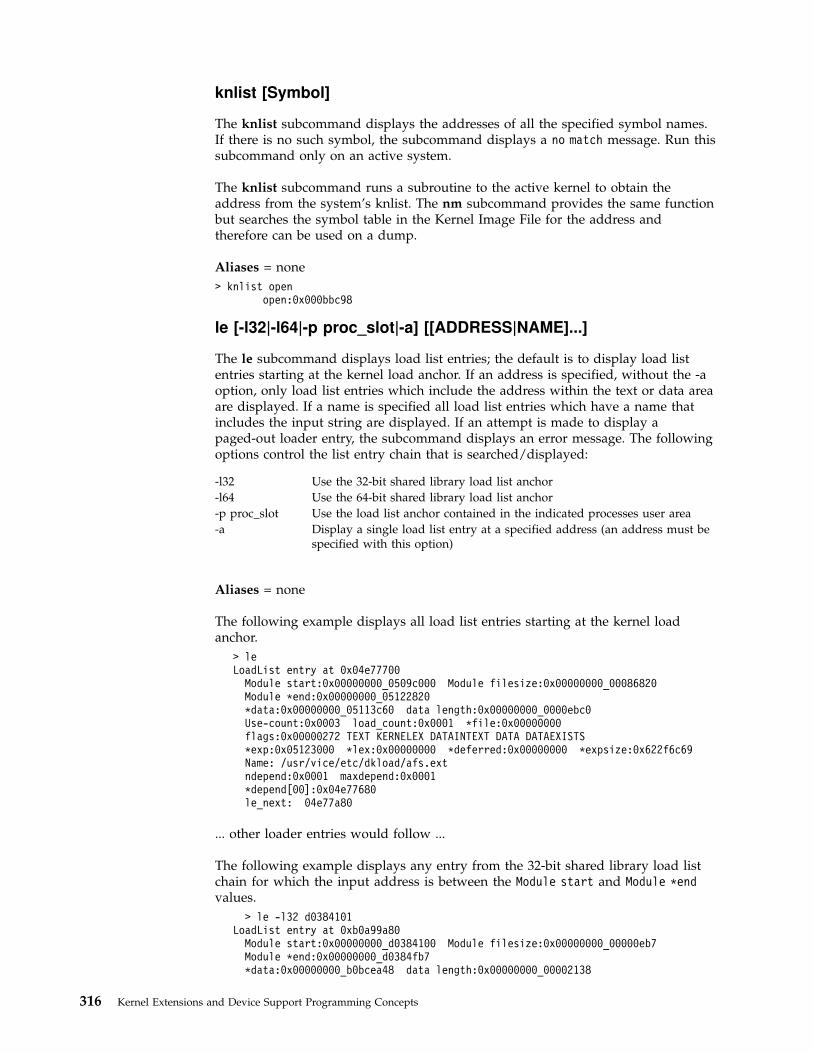
knlist [Symbol]
The knlist subcommand displays the addresses of all the specified symbol names.If there is no such symbol, the subcommand displays a no match message. Run thissubcommand only on an active system.
The knlist subcommand runs a subroutine to the active kernel to obtain theaddress from the system’s knlist. The nm subcommand provides the same functionbut searches the symbol table in the Kernel Image File for the address andtherefore can be used on a dump.
Aliases = none
> knlist openopen:0x000bbc98
le [-l32|-l64|-p proc_slot|-a] [[ADDRESS|NAME]...]
The le subcommand displays load list entries; the default is to display load listentries starting at the kernel load anchor. If an address is specified, without the -aoption, only load list entries which include the address within the text or data areaare displayed. If a name is specified all load list entries which have a name thatincludes the input string are displayed. If an attempt is made to display apaged-out loader entry, the subcommand displays an error message. The followingoptions control the list entry chain that is searched/displayed:
-l32 Use the 32-bit shared library load list anchor
-l64 Use the 64-bit shared library load list anchor
-p proc_slot Use the load list anchor contained in the indicated processes user area
-a Display a single load list entry at a specified address (an address must bespecified with this option)
Aliases = none
The following example displays all load list entries starting at the kernel loadanchor.
> leLoadList entry at 0x04e77700
Module start:0x00000000_0509c000 Module filesize:0x00000000_00086820Module *end:0x00000000_05122820*data:0x00000000_05113c60 data length:0x00000000_0000ebc0Use-count:0x0003 load_count:0x0001 *file:0x00000000flags:0x00000272 TEXT KERNELEX DATAINTEXT DATA DATAEXISTS*exp:0x05123000 *lex:0x00000000 *deferred:0x00000000 *expsize:0x622f6c69Name: /usr/vice/etc/dkload/afs.extndepend:0x0001 maxdepend:0x0001*depend[00]:0x04e77680le_next: 04e77a80
... other loader entries would follow ...
The following example displays any entry from the 32-bit shared library load listchain for which the input address is between the Module start and Module *endvalues.
> le -l32 d0384101LoadList entry at 0xb0a99a80
Module start:0x00000000_d0384100 Module filesize:0x00000000_00000eb7Module *end:0x00000000_d0384fb7*data:0x00000000_b0bcea48 data length:0x00000000_00002138
316 Kernel Extensions and Device Support Programming Concepts

Use-count:0x0001 load_count:0x0000 *file:0x10000c30flags:0x000000c0 DATA LIBRARY*exp:0xb0acb300 *lex:0x00000000 *deferred:0x00000000 *expsize:0x00000000Name: /usr/lib/libdbm.a shr.ondepend:0x0002 maxdepend:0x0002*depend[00]:0xb004c780*depend[01]:0xb03afd80le_next: b0a99a00
The following example displays load list entries for the process in process slot 20.
> le -p 20LoadList entry at 0x2ff7f480
Module start:0x00000000_d0bc6000 Module filesize:0x00000000_00000304Module *end:0x00000000_d0bc6304*data:0x00000000_201541f0 data length:0x00000000_0000006cUse-count:0x0002 load_count:0x0001 *file:0x10002370flags:0x00001240 DATA DATAEXISTS DATAMAPPED*exp:0x2ff81040 *lex:0x00000000 *deferred:0x00000000 *expsize:0x00000000Name: /opt/dcelocal/ext/dfsloadobjndepend:0x0002 maxdepend:0x0002*depend[00]:0xf0263d80*depend[01]:0x04e77a80le_next: 2ff7f400
... other loader entries would follow ...
Any of the above examples could include either addresses or names as additionalarguments. These additional arguments would simply limit the entries displayed tothose that contain the input addresses or names.
The following example displays a loader entry at a specified address.
> le -a 4e77500LoadList entry at 0x04e77500
Module start:0x00000000_04fb0000 Module filesize:0x00000000_00000e88Module *end:0x00000000_04fb0e88*data:0x00000000_00000012 data length:0x00000000_00000000Use-count:0x0002 load_count:0x0000 *file:0x00000000flags:0x00000248 SYSCALLS DATA DATAEXISTS*exp:0x04fb1000 *lex:0x00000000 *deferred:0x00000000 *expsize:0x00010ca4Name: /unixndepend:0x0002 maxdepend:0x0002*depend[00]:0x04e77080*depend[01]:0x04e77480le_next: 04cb3000
linkblk
The linkblk subcommand displays the streams linkblk table. Refer to the/usr/include/sys/stream.h file for the linkblk structure definitions. If there are nolinkblk structures found on the system, the linkblk subcommand will print amessage stating that no structures are found.
This subcommand can be issued from crash on either a running system or asystem dump.
Aliases = lblk
This example shows a regular link:
> linkblkQTOP QBOT INDEX
5ab8b74 5ae5074 5ab4200
Chapter 17. Debugging Tools 317
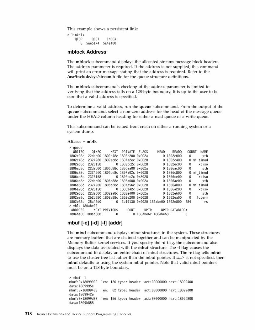
This example shows a persistent link:
> linkblkQTOP QBOT INDEX
0 5ae5174 5a4ef00
mblock Address
The mblock subcommand displays the allocated streams message-block headers.The address parameter is required. If the address is not supplied, this commandwill print an error message stating that the address is required. Refer to the/usr/include/sys/stream.h file for the queue structure definitions.
The mblock subcommand’s checking of the address parameter is limited toverifying that the address falls on a 128-byte boundary. It is up to the user to besure that a valid address is specified.
To determine a valid address, run the queue subcommand. From the output of thequeue subcommand, select a non-zero address for the head of the message queueunder the HEAD column heading for either a read queue or a write queue.
This subcommand can be issued from crash on either a running system or asystem dump.
Aliases = mblk
> queueWRITEQ QINFO NEXT PRIVATE FLAGS HEAD READQ COUNT NAME
1802c08c 22dac00 1802c48c 1802c200 0x002a 0 1802c000 0 sth1802c48c 2324960 1802ec8c 1807a2ec 0x0028 0 1802c400 0 mi_timod1802ec8c 2320158 0 1802cc2c 0x8028 0 1802ec00 0 xtiso1806ac8c 22dac00 1806c88c 1806aa00 0x002a 0 1806ac00 0 sth1806c88c 2324960 1806ce8c 1807a02c 0x0028 0 1806c800 0 mi_timod1806ce8c 2320158 0 1806cc2c 0x8028 0 1806ce00 0 xtiso1806ae8c 22dac00 1806a88c 1806a000 0x002a 0 1806ae00 0 sth1806a88c 2324960 1806a28c 1807a56c 0x0028 0 1806a800 0 mi_timod1806a28c 2320158 0 1806a42c 0x8028 0 1806a200 0 xtiso1802e68c 22dac00 1802ea8c 1802e400 0x002a 0 1802e600 0 sth1802ea8c 2b2b580 1802e88c 1802e200 0x0028 0 1802ea00 0 ldterm1802e88c 25a48d0 0 2b19130 0x0020 180abe00 1802e800 684 rs> mblk 180abe00ADDRESS NEXT PREVIOUS CONT RPTR WPTR DATABLOCK
180abe00 180ab800 0 0 180abe6c 180abeb8 0
mbuf [-c] [-d] [-l] [addr]
The mbuf subcommand displays mbuf structures in the system. These structuresare memory buffers that are chained together and can be manipulated by theMemory Buffer kernel services. If you specify the -d flag, the subcommand alsodisplays the data associated with the mbuf structure. The -l flag causes thesubcommand to display an entire chain of mbuf structures. The -c flag tells mbufto use the cluster free list rather than the mbuf pointer. If addr is not specified, thenmbuf defaults to using the system mbuf pointer. Note that valid mbuf pointersmust be on a 128-byte boundary.
> mbuf -lmbuf:0x18099900 len: 120 type: header act:00000000 next:18099400data:1809995embuf:0x18099400 len: 62 type: header act:00000000 next:18099d00data:1809942embuf:0x18099d00 len: 156 type: header act:00000000 next:18096800data:1809b858
318 Kernel Extensions and Device Support Programming Concepts

mbuf:0x18096800 len: 156 type: header act:00000000 next:18099300data:1809b858mbuf:0x18099300 len: 62 type: header act:00000000 next:18099700data:1809932embuf:0x18099700 len: 4 type: data act:00000000 next:18099500data:180a103e...
mst [-f] [Address] . . .
Displays the mstsave portion of the uthread structure at the addresses specified(see the uthread.h and mstsave.h header files in /usr/include/sys). If you do notspecify an address, it displays all of the mstsave entries on the current save area(CSA) chain except the first. If you specify the -f flag the first mstsave area on theCSA chain displays.
Aliases = none
ndb
Displays network kernel data structures either for a running system or a systemdump. The ndb (network debugger) subcommand displays the following options:
? Provides first-level help information.
help Provides additional help information.
tcb [Addr] Shows TCBs. The default is HEAD TCB.
udb [Addr] Shows UDBs. The default is HEAD UDB.
sockets Shows sockets from the file table.
mbuf [Addr] Shows the mbuf at the specified address.
ifnet [Addr] Shows the ifnet structures at the specified address.
quit Stops the running option.
xit Exits the ndb submenu.
Aliases = none
nm [Symbol]
The nm subcommand displays the symbol value and type found in KernelFile.
Aliases = none
> nm open00095484 000C70 PR SD <.open>00095484 PR LD .open000BBC98 00000C SV SD open
od [ldr:] [vmm:] [*...] [SymbolName | Address] [Count] [Format]
The od subcommand dumps the number of data values specified by Count startingat the SymbolName value or Address according to Format. Possible formats are octal,longoct, decimal, longdec, character, hex, instruction, and byte. The default is hex.Note that if you use the Format parameter, you must also use Count. If theSymbolName or Address is proceeded by an asterisk, then the symbol or address isdereferenced before displaying the data. Additionally, the strings ldr: and vmm:may be used to indicate that addresses are to be considered loader or VMMaddresses, just as if the cm ldron and/or cm vmmon subcommands had beenissued.
Chapter 17. Debugging Tools 319

The od subcommand is especially useful during program development in order tosee structure values at a given point in time.
Aliases = none
> od open 1000095484: 7c0802a6 bf21ffe4 90010008 9421ff3000095494: 609c0000 832202e0 607b0000 60bd0000000954a4: 63230000 38800000> od open 10 byte00095484: 0174 0010 0002 0246 0277 0041 0377 03440009548c: 0220 0001> od 12345warning: word alignment performed00012344: 480001d8> user -s 3MST Segment Regs
0:0x00000000 1:0x00002c0b 2:0x00004411 3:0x007fffff4:0x007fffff 5:0x007fffff 6:0x007fffff 7:0x007fffff8:0x007fffff 9:0x007fffff 10:0x007fffff 11:0x007fffff
12:0x007fffff 13:0x007fffff 14:0x00001004 15:0x007fffff...> od 4411:ff3b400 12004411:ff3b400: 00000000 00000000 2ff22e28 00000000004411:ff3b410: 00000306 00000000 0002a7ec 000010b0004411:ff3b420: 82202220 0002a7ec 00000000 0000001c> od Debug_record001cc378: 00000000> od *Debug_record00000000: 00000000
ppd [ProcessorNumber | *]
Displays per-processor data area (PPDA) structures for the specified processor. Ifno processor is specified, the current processor selected by the cpu subcommand isused. If the asterisk argument is given, the PPDA of every enabled processor isdisplayed.
Aliases = none
> ppdPer Processor Data Area for processor 0alsave[ 0]...............0000000000000000alsave[ 1]...............0000000000000000alsave[ 2]...............0000000000000000alsave[ 3]...............0000000000000000alsave[ 4]...............0000000000000000alsave[ 5]...............0000000000000000alsave[ 6]...............0000000000000000alsave[ 7]...............0000000000000000alsave[ 8]...............0000000000000000alsave[ 9]...............0000000000000000alsave[10]...............0000000000000000alsave[11]...............0000000000000000alsave[12]...............0000000000000000alsave[13]...............0000000000000000alsave[14]...............0000000000000000alsave[15]...............0000000000000000csa......................003f0eb0mstack...................003efeb0fpowner..................00000000curthread................e60013ec...
320 Kernel Extensions and Device Support Programming Concepts

print [type] Address
Does dbx-style printing of structures. The -i option must be given on the commandline to use this feature.
If type is omitted, the default type set by the last print -d command is used.
Aliases = none
print -d type
Recognized by the pr, str, or struct subcommand aliases. Sets the default type forsubsequent print commands to type.
Aliases = set prtype
proc [-] [-r] [ProcessSlotNumber]
The proc subcommand displays the process table, including the kernel threadcount (the number of threads in the process) and state of each process. Use the -rflag to display only runnable processes. Use the - flag to display a longer listing ofthe process table.
Aliases = ps, p
>pSLT ST PID PPID PGRP UID EUID TCNT NAME
0 a 0 0 0 0 0 1 swapperFLAGS: swapped_in no_swap fixed_pri kproc
1 a 1 0 0 0 0 1 initFLAGS: swapped_in no_swap
2 a 204 0 0 0 0 1 waitFLAGS: swapped_in no_swap fixed_pri kproc
...>p 20SLT ST PID PPID PGRP UID EUID TCNT NAME20 a 1406 1 1406 0 0 1 ksh
FLAGS: swapped_in no_swap> p - 0SLT ST PID PPID PGRP UID EUID TCNT NAME
0 a 0 0 0 0 0 1 swapperFLAGS: swapped_in no_swap fixed_pri kproc
Links: *child:0xe30013b0 *siblings:0x00000000 *uidl:0xe3002490*ganchor:0x00000000 *pgrpl:0x00000000 *ttyl:0x00000000
Dispatch Fields: pevent:0x00000000 *synch:0xfffffffflock:0x00000000 lock_d:0x00000000
Thread Fields: *threadlist:0xe6000000 threadcount:1active:1 suspended:0 local:0 terminating:0Scheduler Fields: fixed pri: 16 repage:0x00000000 scount:0 sched_pri:0
*sched_next:0x00000000 *sched_back:0x00000000 cpticks:130msgcnt:0 majfltsec:0
Misc: adspace:0x0000340d kstackseg:0x007fffff xstat:0x0000*p_ipc:0x00000000 *p_dblist:0x00000000 *p_dbnext:0x00000000
Signal Information:pending:hi 0x00000000,lo 0x00000000sigcatch:hi 0x00000000,lo 0x00000000 sigignore:hi 0xffffffff,lo 0xfff7ffff
Statistics: size:0x00000000(pages) audit:0x00000000accounting page frames:0 page space blocks:0
Refer to the sys/proc.h header file for the structure definition.
Chapter 17. Debugging Tools 321
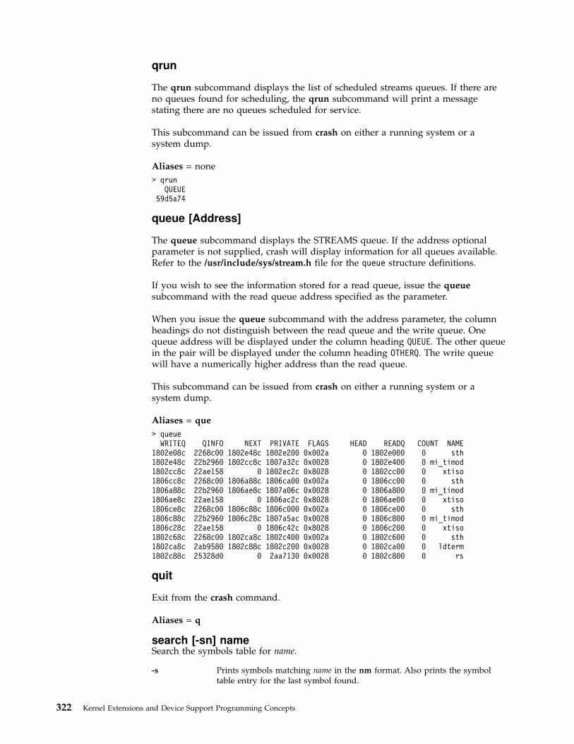
qrun
The qrun subcommand displays the list of scheduled streams queues. If there areno queues found for scheduling, the qrun subcommand will print a messagestating there are no queues scheduled for service.
This subcommand can be issued from crash on either a running system or asystem dump.
Aliases = none
> qrunQUEUE
59d5a74
queue [Address]
The queue subcommand displays the STREAMS queue. If the address optionalparameter is not supplied, crash will display information for all queues available.Refer to the /usr/include/sys/stream.h file for the queue structure definitions.
If you wish to see the information stored for a read queue, issue the queuesubcommand with the read queue address specified as the parameter.
When you issue the queue subcommand with the address parameter, the columnheadings do not distinguish between the read queue and the write queue. Onequeue address will be displayed under the column heading QUEUE. The other queuein the pair will be displayed under the column heading OTHERQ. The write queuewill have a numerically higher address than the read queue.
This subcommand can be issued from crash on either a running system or asystem dump.
Aliases = que
> queueWRITEQ QINFO NEXT PRIVATE FLAGS HEAD READQ COUNT NAME
1802e08c 2268c00 1802e48c 1802e200 0x002a 0 1802e000 0 sth1802e48c 22b2960 1802cc8c 1807a32c 0x0028 0 1802e400 0 mi_timod1802cc8c 22ae158 0 1802ec2c 0x8028 0 1802cc00 0 xtiso1806cc8c 2268c00 1806a88c 1806ca00 0x002a 0 1806cc00 0 sth1806a88c 22b2960 1806ae8c 1807a06c 0x0028 0 1806a800 0 mi_timod1806ae8c 22ae158 0 1806ac2c 0x8028 0 1806ae00 0 xtiso1806ce8c 2268c00 1806c88c 1806c000 0x002a 0 1806ce00 0 sth1806c88c 22b2960 1806c28c 1807a5ac 0x0028 0 1806c800 0 mi_timod1806c28c 22ae158 0 1806c42c 0x8028 0 1806c200 0 xtiso1802c68c 2268c00 1802ca8c 1802c400 0x002a 0 1802c600 0 sth1802ca8c 2ab9580 1802c88c 1802c200 0x0028 0 1802ca00 0 ldterm1802c88c 25328d0 0 2aa7130 0x0028 0 1802c800 0 rs
quit
Exit from the crash command.
Aliases = q
search [-sn] nameSearch the symbols table for name.
-s Prints symbols matching name in the nm format. Also prints the symboltable entry for the last symbol found.
322 Kernel Extensions and Device Support Programming Concepts
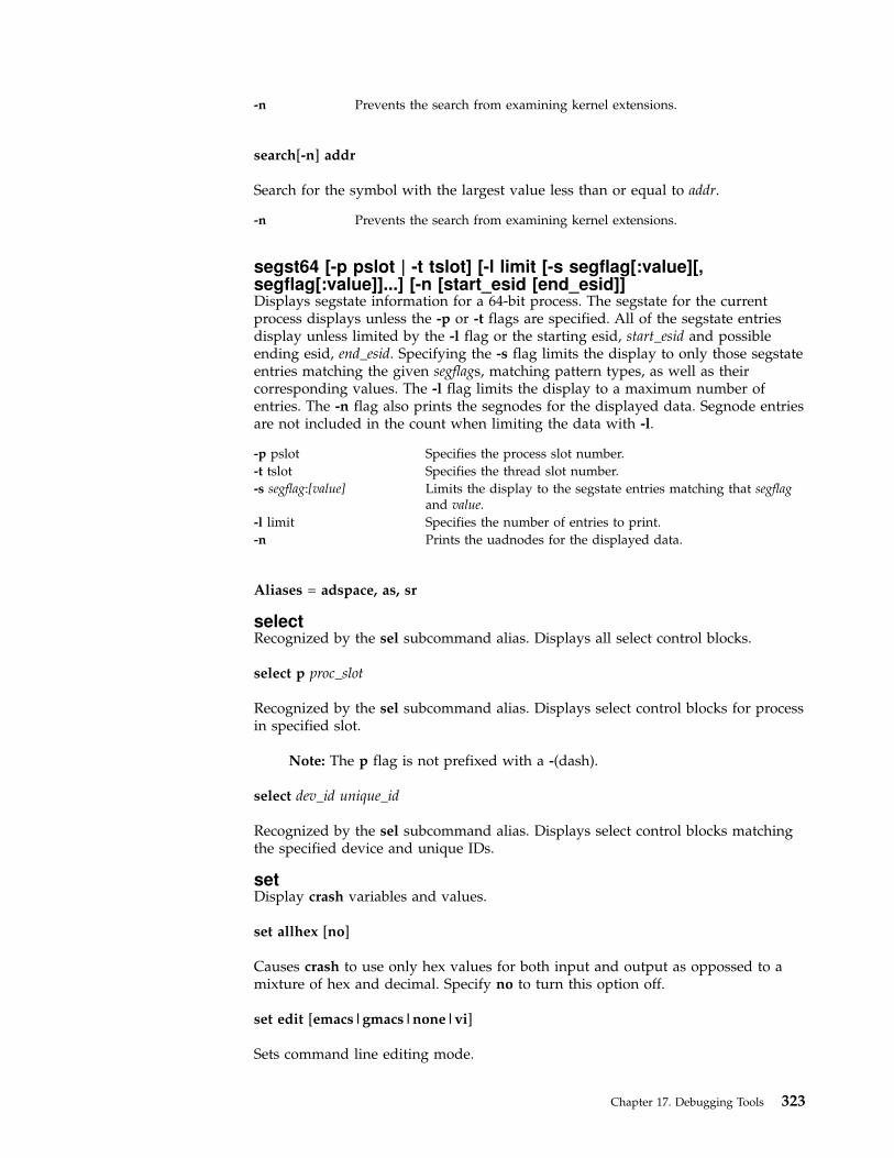
-n Prevents the search from examining kernel extensions.
search[-n] addr
Search for the symbol with the largest value less than or equal to addr.
-n Prevents the search from examining kernel extensions.
segst64 [-p pslot | -t tslot] [-l limit [-s segflag[:value][,segflag[:value]]...] [-n [start_esid [end_esid]]Displays segstate information for a 64-bit process. The segstate for the currentprocess displays unless the -p or -t flags are specified. All of the segstate entriesdisplay unless limited by the -l flag or the starting esid, start_esid and possibleending esid, end_esid. Specifying the -s flag limits the display to only those segstateentries matching the given segflags, matching pattern types, as well as theircorresponding values. The -l flag limits the display to a maximum number ofentries. The -n flag also prints the segnodes for the displayed data. Segnode entriesare not included in the count when limiting the data with -l.
-p pslot Specifies the process slot number.
-t tslot Specifies the thread slot number.
-s segflag:[value] Limits the display to the segstate entries matching that segflagand value.
-l limit Specifies the number of entries to print.
-n Prints the uadnodes for the displayed data.
Aliases = adspace, as, sr
selectRecognized by the sel subcommand alias. Displays all select control blocks.
select p proc_slot
Recognized by the sel subcommand alias. Displays select control blocks for processin specified slot.
Note: The p flag is not prefixed with a -(dash).
select dev_id unique_id
Recognized by the sel subcommand alias. Displays select control blocks matchingthe specified device and unique IDs.
setDisplay crash variables and values.
set allhex [no]
Causes crash to use only hex values for both input and output as oppossed to amixture of hex and decimal. Specify no to turn this option off.
set edit [emacs|gmacs|none|vi]
Sets command line editing mode.
Chapter 17. Debugging Tools 323

set fpregs [yes|no|auto]
Specify whether or not floating-point registers should be displayed. If auto is used,the fpeu variable in the mstsave area determines when to display the registers.
set idarch [ppc|pwr|auto]
Set instruction decode architecture. auto detects the architecture from the system.
set logfile [filename]
Set logfile to given name, or turn off logging if no name is given.
set loglevel [0|1|2]
Set logging granularity to:
0 coarse-only commands will be logged.
1 medium-commands and output to terminal will be logged.
2 fine-commands and all outputs will be logged, including redirected.
set prtype [type]
Set the default print type. This is equivalent to print -d type.
set quiet [no]
Suppress error messages concerning missing or swapped out threads andprocesses. Specify no to turn off this option.
socket [-]
The socket subcommand displays the system socket structures. Use the - flag toalso display the socket buffers.
Aliases = sock
> sock1802e800: type:0x0002 (DGRAM) opts:0x0000 ()
state:0x0082 (ISCONNECTED|PRIV) linger:0x0000pcb:0x1807a6c0 proto:0x000bbd30 q0:0x00000000 q0len:0q:0x00000000 qlen:0 qlimit:0 head:0x00000000timeo:0 error:0 oobmark:0 pgid:0
18074400: type:0x0002 (DGRAM) opts:0x0000 ()state:0x0080 (PRIV) linger:0x0000pcb:0x1807a100 proto:0x000bbd30 q0:0x00000000 q0len:0q:0x00000000 qlen:0 qlimit:0 head:0x00000000timeo:0 error:0 oobmark:0 pgid:0
...
Refer to the sys/socket.h header file for structure definitions.
sr64 [-p pslot | -t tslot] [-l limit [-n [start_esid [end_esid]]Recognized by the segst and seg subcommand aliases. Displays the effectivesegment IDs (esid) and their corresponding segvals for a 64-bit process. If you donot specify the -p or -t flags, sr64 uses the current process. Otherwise, it uses pslotas the process slot number for the desired process, or tslot as the thread slotnumber of a thread contained within the desired process. It lists all entries in theadspace unless a starting esid, start_esid and possible ending esid, end_esid is
324 Kernel Extensions and Device Support Programming Concepts
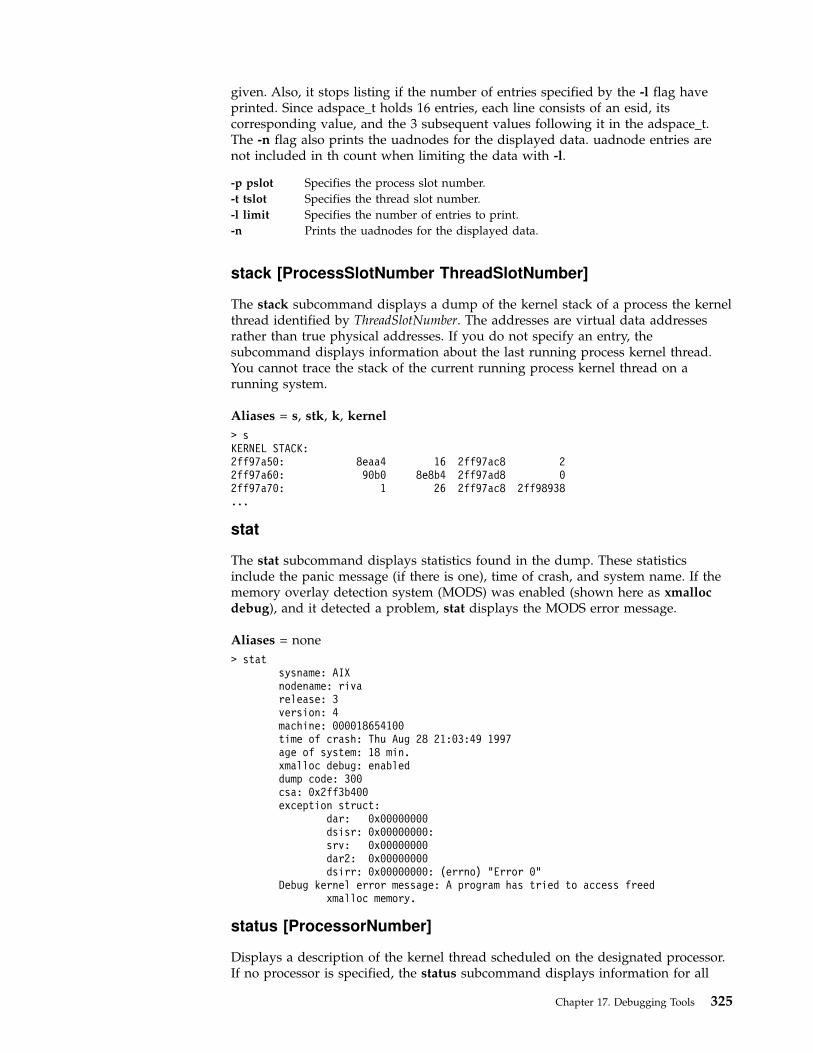
given. Also, it stops listing if the number of entries specified by the -l flag haveprinted. Since adspace_t holds 16 entries, each line consists of an esid, itscorresponding value, and the 3 subsequent values following it in the adspace_t.The -n flag also prints the uadnodes for the displayed data. uadnode entries arenot included in th count when limiting the data with -l.
-p pslot Specifies the process slot number.
-t tslot Specifies the thread slot number.
-l limit Specifies the number of entries to print.
-n Prints the uadnodes for the displayed data.
stack [ProcessSlotNumber ThreadSlotNumber]
The stack subcommand displays a dump of the kernel stack of a process the kernelthread identified by ThreadSlotNumber. The addresses are virtual data addressesrather than true physical addresses. If you do not specify an entry, thesubcommand displays information about the last running process kernel thread.You cannot trace the stack of the current running process kernel thread on arunning system.
Aliases = s, stk, k, kernel
> sKERNEL STACK:2ff97a50: 8eaa4 16 2ff97ac8 22ff97a60: 90b0 8e8b4 2ff97ad8 02ff97a70: 1 26 2ff97ac8 2ff98938...
stat
The stat subcommand displays statistics found in the dump. These statisticsinclude the panic message (if there is one), time of crash, and system name. If thememory overlay detection system (MODS) was enabled (shown here as xmallocdebug), and it detected a problem, stat displays the MODS error message.
Aliases = none
> statsysname: AIXnodename: rivarelease: 3version: 4machine: 000018654100time of crash: Thu Aug 28 21:03:49 1997age of system: 18 min.xmalloc debug: enableddump code: 300csa: 0x2ff3b400exception struct:
dar: 0x00000000dsisr: 0x00000000:srv: 0x00000000dar2: 0x00000000dsirr: 0x00000000: (errno) "Error 0"
Debug kernel error message: A program has tried to access freedxmalloc memory.
status [ProcessorNumber]
Displays a description of the kernel thread scheduled on the designated processor.If no processor is specified, the status subcommand displays information for all
Chapter 17. Debugging Tools 325

processors. The information displayed includes the processor number, kernelthread identifier, kernel thread table slot, process identifier, process table slot, andprocess name.
Aliases = none
> status 0CPU TID TSLOT PID PSLOT PROC_NAME
0 1fe1 31 1fd8 31 crash
stream
The stream subcommand displays the stream head table. The information printedis contained in an internal structure. The following members of this internalstructure are described here:
address Address of stream head
wq Address of streams write queue
dev Associated device number of the stream
read error Read error on the stream
write_error Write error on the stream
flags Stream head flag values
push_cnt Number of modules pushed on the stream
wroff Write offset to prepend M_DATA
ioc_id ID of outstanding M_IOCTL request
pollq List of active polls
sigsq List of active M_SETSIGs
The flags structure member, if set, is based on combinations of the followingvalues:
#define Value Description
F_STH_READ_ERROR 0x0001 M_ERROR with read errorreceived, fail all read calls.
F_STH_WRITE_ERROR 0x0002 M_ERROR with write errorreceived, fail all writes.
F_STH_HANGUP 0x0004 M_HANGUP received, nomore data.
F_STH_NDELON 0x0008 Do TTY semantics forONDELAY handling.
F_STH_ISATTY 0x0010 This stream acts a terminal.
F_STH_MREADON 0x0020 Generate M_READ messages.
F_STH_TOSTOP 0x0040 Disallow background writes(for job control).
F_STH_PIPE 0x0080 Stream is one end of a pipeor FIFO.
F_STH_WPIPE 0x0100 Stream is the ″write″ side ofa pipe.
F_STH_FIFO 0x0200 Stream is a FIFO.
F_STH_LINKED 0x0400 Stream has one or morelower streams linked.
F_STH_CTTY 0x0800 Stream controlling tty.
326 Kernel Extensions and Device Support Programming Concepts
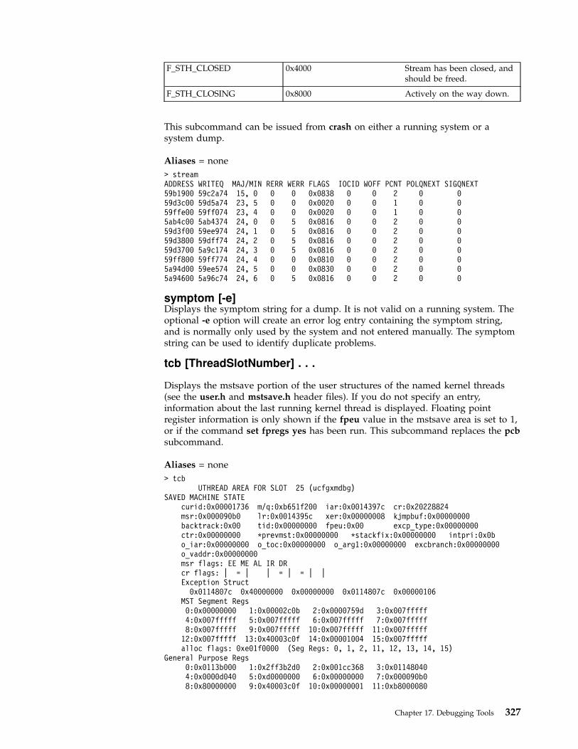
F_STH_CLOSED 0x4000 Stream has been closed, andshould be freed.
F_STH_CLOSING 0x8000 Actively on the way down.
This subcommand can be issued from crash on either a running system or asystem dump.
Aliases = none
> streamADDRESS WRITEQ MAJ/MIN RERR WERR FLAGS IOCID WOFF PCNT POLQNEXT SIGQNEXT59b1900 59c2a74 15, 0 0 0 0x0838 0 0 2 0 059d3c00 59d5a74 23, 5 0 0 0x0020 0 0 1 0 059ffe00 59ff074 23, 4 0 0 0x0020 0 0 1 0 05ab4c00 5ab4374 24, 0 0 5 0x0816 0 0 2 0 059d3f00 59ee974 24, 1 0 5 0x0816 0 0 2 0 059d3800 59dff74 24, 2 0 5 0x0816 0 0 2 0 059d3700 5a9c174 24, 3 0 5 0x0816 0 0 2 0 059ff800 59ff774 24, 4 0 0 0x0810 0 0 2 0 05a94d00 59ee574 24, 5 0 0 0x0830 0 0 2 0 05a94600 5a96c74 24, 6 0 5 0x0816 0 0 2 0 0
symptom [-e]Displays the symptom string for a dump. It is not valid on a running system. Theoptional -e option will create an error log entry containing the symptom string,and is normally only used by the system and not entered manually. The symptomstring can be used to identify duplicate problems.
tcb [ThreadSlotNumber] . . .
Displays the mstsave portion of the user structures of the named kernel threads(see the user.h and mstsave.h header files). If you do not specify an entry,information about the last running kernel thread is displayed. Floating pointregister information is only shown if the fpeu value in the mstsave area is set to 1,or if the command set fpregs yes has been run. This subcommand replaces the pcbsubcommand.
Aliases = none
> tcbUTHREAD AREA FOR SLOT 25 (ucfgxmdbg)
SAVED MACHINE STATEcurid:0x00001736 m/q:0xb651f200 iar:0x0014397c cr:0x20228824msr:0x000090b0 lr:0x0014395c xer:0x00000008 kjmpbuf:0x00000000backtrack:0x00 tid:0x00000000 fpeu:0x00 excp_type:0x00000000ctr:0x00000000 *prevmst:0x00000000 *stackfix:0x00000000 intpri:0x0bo_iar:0x00000000 o_toc:0x00000000 o_arg1:0x00000000 excbranch:0x00000000o_vaddr:0x00000000msr flags: EE ME AL IR DRcr flags: | = | | = | = | |Exception Struct
0x0114807c 0x40000000 0x00000000 0x0114807c 0x00000106MST Segment Regs0:0x00000000 1:0x00002c0b 2:0x0000759d 3:0x007fffff4:0x007fffff 5:0x007fffff 6:0x007fffff 7:0x007fffff8:0x007fffff 9:0x007fffff 10:0x007fffff 11:0x007fffff
12:0x007fffff 13:0x40003c0f 14:0x00001004 15:0x007fffffalloc flags: 0xe01f0000 (Seg Regs: 0, 1, 2, 11, 12, 13, 14, 15)
General Purpose Regs0:0x0113b000 1:0x2ff3b2d0 2:0x001cc368 3:0x011480404:0x0000d040 5:0xd0000000 6:0x00000000 7:0x000090b08:0x80000000 9:0x40003c0f 10:0x00000001 11:0xb8000080
Chapter 17. Debugging Tools 327

12:0x034123f0 13:0xdeadbeef 14:0xdeadbeef 15:0xdeadbeef16:0xdeadbeef 17:0xdeadbeef 18:0x20000474 19:0xdeadbeef20:0xdeadbeef 21:0xdeadbeef 22:0xdeadbeef 23:0xdeadbeef24:0x2ff3b6e0 25:0x2ff3b400 26:0x100002e4 27:0x4242442428:0xe3002058 29:0xe60013ec 30:0x00143dac 31:0x00000000
Kernel stack address: 0x2ff3b400
thread [-] [-r] [-p ProcessSlotNumber | -a Address |ThreadSlotNumber]
Displays the contents of the kernel thread table. The - (minus) flag displays alonger listing of the thread table. The -r flag displays only runnable kernel threads.The -p flag displays only those kernel threads which belong to the processidentified by ProcessSlotNumber. The -a flag displays the kernel thread structure atAddress. If ThreadSlotNumber is given, only the corresponding kernel thread isdisplayed.
Aliases = th
> thread 1SLT ST TID PID CPUID POLICY PRI CPU EVENT PROCNAME
1 s 1e1 1 unbound other 3c 0 initFLAGS: wakeonsig
> thSLT ST TID PID CPUID POLICY PRI CPU EVENT PROCNAME
0 s 3 0 0 FIFO 10 78 swappert_flags: wakeonsig kthread
1 s 105 1 0 other 3c 0 initt_flags: wakeonsig
2 r 205 204 0 FIFO 7f 78 waitt_flags: sig_avail kthread
3 s 307 306 0 RR 24 0 netmt_flags: sig_avail kthread
...> th - 3SLT ST TID PID CPUID POLICY PRI CPU EVENT PROCNAME
3 s 307 306 0 RR 24 0 netmt_flags: sig_avail kthread
Links: *procp:0xe3000438 *uthreadp:0x2ff3b400 *userp:0x2ff3b6e0*prevthread:0xe6000264 *nextthread:0xe6000264, *stackp:0x00000000*wchan1(real):0x00000000 *wchan2(VMM):0x00000000 *swchan:0x00000000wchan1sid:0x00000000 wchan1offset:0x00000000pevent:0x00000000 wevent:0x00000912 *slist:0x00000000
Dispatch Fields: *prior:0xe6000264 *next:0xe6000264polevel:0x00000000 ticks:0x0000 *synch:0xffffffff result:0x00000000*eventlst:0x00000000 *wchan(hashed):0x00000000 suspend:0x0001thread waiting for: event(s)
Scheduler Fields: cpuid:0x0000 scpuid:0x0000 pri: 36 policy:RRaffinity:0x0000 cpu:0x0000 lpri: 0 wpri:127 time:0xff
sav_pri:0x24Misc: lockcount:0x00000000 ulock:0x00000000 *graphics:0x00000000
dispct:0x0000a5ae fpuct:0x00000000 boosted:0x0000userdata:0x00000000
Signal Information: cursig:0x00 *scp:0x00000000pending:hi 0x00000000,lo 0x00000000 sigmask:hi 0x00000000,lo 0x00000000
trace [-r | -m [-f]] [-k | -s] [-r] [ThreadSlotNumber] . . .The trace subcommand displays a kernel stack trace of the process kernel threadidentified by ThreadSlotNumber. The trace starts at the top of the stack and attemptsto find valid stack frames deeper in the stack. By default, the current processkernel thread is used.
328 Kernel Extensions and Device Support Programming Concepts

When using the -k flag, the stack frame addresses indicate the stack framecontaining the link register of the function that is displayed. The -m flag causestrace to display the traceback associated with each mstsave area on the currentsave area chain, except the first. To see a traceback from the first mstsave area,specify the -f flag. When either the -m or -k flags are used, trace may also showthe LR (link register)and top stack frame pointer. These are not part of the stacktrace and are therefore marked with an asterisk. The -s flag displays saved registerinformation for each stack frame.
Use the -r flag to use the kernel frame pointer set up by the kfp subcommand asthe starting address instead of the frame pointer found in the SystemImageFile. Thetrace subcommand stops and reports an error if an invalid frame pointer isencountered.
Aliases = t
> tSTACK TRACE:
.et_wait ()
.e_sleep ()
.e_sleepl ()
.sleepx ()
.fifo_read ()
.fifo_rdwr ()
.vno_rw ()
.rwuio ()
.rdwr ()
.kreadv ()
> t -k 5STACK TRACE:0x2ff3b400 (excpt=2ef636d8:40000000:00004812:2ef636d8:00000106) (intpri=0)
IAR: .e_block_thread+23c (00029e04): l r0,0xc(r30)LR: .e_block_thread+23c (00029e04)2ef62ee8: .e_sleep_thread+ec (0002a454)2ef62f48: .netisr_thread+28 (0006f854)2ef62f88: .threadentry+18 (00047244)2ef62fc8: .low+0 (00000000)
tty
Aliases = term, dz, dh
Refer to the sys/tty.h header file for the structure definition.
unhide symbol...
Unhide the specified symbol. See “hide symbol...” on page 315.
unhide
Unhide all hidden symbols. See the hide symbol... subcommand on “hidesymbol...” on page 315.
user [ThreadSlotNumber]
Recognized by the uarea, u_area, and u subcommand aliases. Displays the uthreadstructure and the associated user structure of the thread identified byThreadSlotNumber. (See the/usr/include/sys/user.h file for the user structuredefinition.) If you do not specify the entry, the information about the last runningthread displays. The -s flag limits the output to segment register information.
Chapter 17. Debugging Tools 329
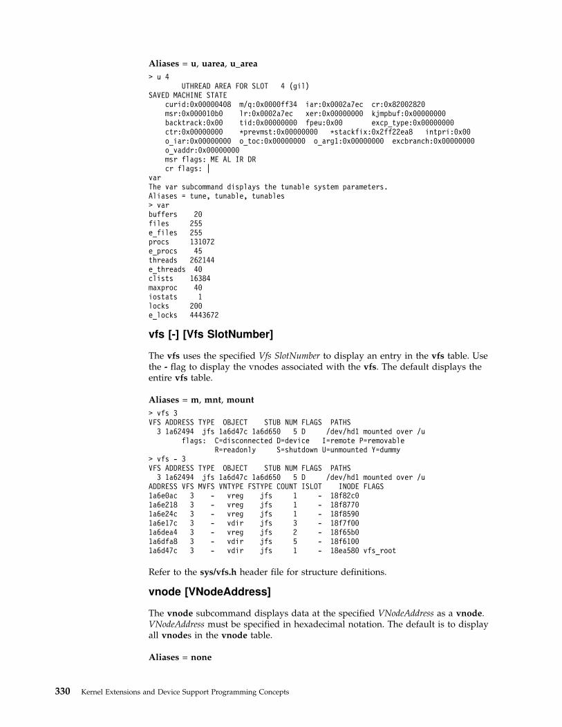
Aliases = u, uarea, u_area
> u 4UTHREAD AREA FOR SLOT 4 (gil)
SAVED MACHINE STATEcurid:0x00000408 m/q:0x0000ff34 iar:0x0002a7ec cr:0x82002820msr:0x000010b0 lr:0x0002a7ec xer:0x00000000 kjmpbuf:0x00000000backtrack:0x00 tid:0x00000000 fpeu:0x00 excp_type:0x00000000ctr:0x00000000 *prevmst:0x00000000 *stackfix:0x2ff22ea8 intpri:0x00o_iar:0x00000000 o_toc:0x00000000 o_arg1:0x00000000 excbranch:0x00000000o_vaddr:0x00000000msr flags: ME AL IR DRcr flags: |
varThe var subcommand displays the tunable system parameters.Aliases = tune, tunable, tunables> varbuffers 20files 255e_files 255procs 131072e_procs 45threads 262144e_threads 40clists 16384maxproc 40iostats 1locks 200e_locks 4443672
vfs [-] [Vfs SlotNumber]
The vfs uses the specified Vfs SlotNumber to display an entry in the vfs table. Usethe - flag to display the vnodes associated with the vfs. The default displays theentire vfs table.
Aliases = m, mnt, mount
> vfs 3VFS ADDRESS TYPE OBJECT STUB NUM FLAGS PATHS
3 1a62494 jfs 1a6d47c 1a6d650 5 D /dev/hd1 mounted over /uflags: C=disconnected D=device I=remote P=removable
R=readonly S=shutdown U=unmounted Y=dummy> vfs - 3VFS ADDRESS TYPE OBJECT STUB NUM FLAGS PATHS
3 1a62494 jfs 1a6d47c 1a6d650 5 D /dev/hd1 mounted over /uADDRESS VFS MVFS VNTYPE FSTYPE COUNT ISLOT INODE FLAGS1a6e0ac 3 - vreg jfs 1 - 18f82c01a6e218 3 - vreg jfs 1 - 18f87701a6e24c 3 - vreg jfs 1 - 18f85901a6e17c 3 - vdir jfs 3 - 18f7f001a6dea4 3 - vreg jfs 2 - 18f65b01a6dfa8 3 - vdir jfs 5 - 18f61001a6d47c 3 - vdir jfs 1 - 18ea580 vfs_root
Refer to the sys/vfs.h header file for structure definitions.
vnode [VNodeAddress]
The vnode subcommand displays data at the specified VNodeAddress as a vnode.VNodeAddress must be specified in hexadecimal notation. The default is to displayall vnodes in the vnode table.
Aliases = none
330 Kernel Extensions and Device Support Programming Concepts

> vnode 1a6e078ADDRESS VFS MVFS VNTYPE FSTYPE COUNT ISLOT DATAPTR FLAGS1a6e078 0 - vreg jfs 4 - 18f6790Total VNODES printed 1
Refer to the sys/vnode.h header file for the structure definition.
xmalloc
Recognized by the xm and malloc subcommand aliases. Prints informationconcerning the allocation and usage of kernel memory (the pinned_heap and thekernel_heap). If a MODS-related system crash has occurred, xmalloc displaysinformation about the address involved in the crash (if available).
xmalloc [addr]
Recognized by the xm and malloc subcommand aliases. Prints xmalloc informationabout addr.
xmalloc -s [addr]
Recognized by the xm and malloc subcommand aliases. Prints debug xmallocallocation records associated with addr.
Note: The -s flag requires that the memory overlay detection system (MODS)has been turned on.
xmalloc -h [addr]
Recognized by the xm and malloc subcommand aliases. Prints MODS xmalloc freelist records associated with addr.
Note: The -h flag requires that the memory overlay detection system (MODS)has been turned on.
xmalloc [-l] -f
Recognized by the xm and malloc subcommand aliases. Prints allocation recordson free list from earliest-freed to latest-freed. The -l flag prints a long listing.
Note: The -f flag requires that the memory overlay detection system (MODS)has been turned on.
xmalloc [-l] -a
Recognized by the xm and malloc subcommand aliases. Prints the allocation recordtable. The -l flag prints a long listing.
Note: The -a flag requires that the memory overlay detection system (MODS)has been turned on.
xmalloc [-l] -p pageno
Recognized by the xm and malloc subcommand aliases. Prints page descriptorinformation for page pageno. The -l flag prints additional information.
xmalloc -d [addr]
Chapter 17. Debugging Tools 331

Recognized by the xm and malloc subcommand aliases. Prints debug xmallocallocation record hash chain associated with the record hash value for addr.
xmalloc -v
Recognized by the xm and malloc subcommand aliases. Verify allocation trailers ofallocated records, and free fill patterns of freed records.
Note: The -v flag requires that the memory overlay detection system (MODS)has been turned on.
Low Level Kernel Debugger (LLDB)
This chapter provides information about the available procedures for debugging adevice driver which is under development. Topics discussed include:
v LLDB Kernel Debug Program
v LLDB Kernel Debug Program Commands
v Maps and Listing as Tools for the LLDB Kernel Debug Program
v Using the LLDB Kernel Debug Program
v Error Messages for the LLDB Kernel Debug Program
LLDB Kernel Debug ProgramThe Low Level Kernel Debug Program (LLDB) on AIX 4.3 will provide newcommands to display new kernel data added to 64-bit applications support. TheLLDB Kernel Debug Program on AIX 4.3 would now be able to handle all the64-bit user addresses or data that are typed in on the command line whereverapplicable. The user address space ranges from 0x0 through 0x0FFFFFFFFFFFFFFF.
In AIX 4.3, though the kernel execution is always 32-bit, it is possible that while inthe LLDB Kernel Debug Program, the currently active process be a 64-bit programand the current execution mode is in Problem State. It is possible to enter suchstate (henceforth mentioned as 64-bit context) by invoking the debugger from thenative or tty keyboard key sequence.
When the debugger is in 64-bit context, the display format of the screen would bedifferent on AIX 4.3 in order to display 64-bit wide GPRs and other relevant 64-bitwide register contents.
The LLDB Kernel Debug Program on AIX 4.3 also supports debugging 64-bit realmode kernel code. The screen display format would be similar to that of the 64-bitcontext debug mode.
Use the kernel debug program for debugging the kernel, device drivers, and otherkernel extensions. The kernel debug program provides the following functions:
v Setting breakpoints within the kernel or within kernel extensions
v Formatting and displaying selected kernel data structures
v Viewing and modifying memory for any kernel data
v Viewing and modifying memory for kernel instructions
v Modifying the state of the machine by altering system registers
v Displaying 64-bit real mode context when stopped in 64-bit real mode code.
v Setting breakpoints and watchpoints in 64-bit real mode code.
v Allowing step execution of 64-bit real mode code.
332 Kernel Extensions and Device Support Programming Concepts

v Executing a stack trace back when stopped in 64-bit real mode code.
Loading and Starting the LLDB Kernel Debug Program
The kernel debug program must be loaded by using the bosboot command beforeit can be started. Use either of the following commands:
bosboot -a -d /dev/ipldevice -D
OR
bosboot -a -d /dev/ipldevice -I
The -D flag causes the kernel debugger program to be loaded. The -I flag alsocauses the kernel debug program to be loaded, but it is also invoked at systeminitialization. This means that when the system starts, it will trap the kernel debugprogram.
After issuing the bosboot command, you must restart the machine. The kerneldebug program will not be loaded until the system is restarted. When started, thedebug program accepts the commands described in “LLDB Kernel Debug ProgramCommands” on page 338.
If the kernel debug program is invoked during initialization, use the go commandto continue the initialization process.
Notes:
1. The debug program disables all external interrupts while it is inoperation.
2. On AIX Version 4.1.4 systems (and later), it is no longer required that thekey switch be in the service position to operate the kernel debugger. Todebug the kernel program, use the bosboot command with the -D or -Iflags. This change was instituted to allow use of the debugger on systemswithout a key.
Using a Terminal with the LLDB Kernel Debug ProgramThe debug program opens an asynchronous ASCII terminal when it is first started,and subsequently upon being started due to a system halt. Native serial ports arechecked sequentially starting with port 0 (zero). Each port is configured at 9600bps, 8 bits, and no parity. If carrier detect is asserted within 1/10 seconds, then theport is used. Otherwise, the next available native port is checked. This processcontinues until a port is opened or until every native port available on the machinehas been checked. If no native serial port is opened successfully, then the result isunpredictable.
You can only display the kernel debugger on an ASCII terminal connected to anative serial port. The kernel debugger does not support any displays connected toany graphics adapters. The debugger has its own device driver for handling thedisplay terminal. It is also possible to connect a serial line between two machinesand define the serial line port as the port for the console. In that case, use the cucommand to connect to the target machine and run the debugger.
Note: If a serial device, other than a terminal connected to a native serialport, is selected by the kernel debugger, the system may appear to hang up.
Chapter 17. Debugging Tools 333
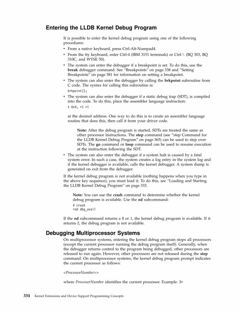
Entering the LLDB Kernel Debug Program
It is possible to enter the kernel debug program using one of the followingprocedures:
v From a native keyboard, press Ctrl-Alt-Numpad4.
v From the tty keyboard, enter Ctrl-4 (IBM 3151 terminals) or Ctrl-\ (BQ 303, BQ310C, and WYSE 50).
v The system can enter the debugger if a breakpoint is set. To do this, use thebreak debugger command. See “Breakpoints” on page 338 and “SettingBreakpoints” on page 381 for information on setting a breakpoint.
v The system can also enter the debugger by calling the brkpoint subroutine fromC code. The syntax for calling this subroutine is:
brkpoint();
v The system can also enter the debugger if a static debug trap (SDT), is compiledinto the code. To do this, place the assembler language instruction:
t 0x4, r1 r1
at the desired address. One way to do this is to create an assembler languageroutine that does this, then call it from your driver code.
Note: After the debug program is started, SDTs are treated the same asother processor instructions. The step command (see “step Command forthe LLDB Kernel Debug Program” on page 365) can be used to step overSDTs. The go command or loop command can be used to resume executionat the instruction following the SDT.
v The system can also enter the debugger if a system halt is caused by a fatalsystem error. In such a case, the system creates a log entry in the system log andif the kernel debugger is available, calls the kernel debugger. A system dump isgenerated on exit from the debugger.
If the kernel debug program is not available (nothing happens when you type inthe above key sequence), you must load it. To do this, see “Loading and Startingthe LLDB Kernel Debug Program” on page 333.
Note: You can use the crash command to determine whether the kerneldebug program is available. Use the od subcommand:
# crash>od dbg_avail
If the od subcommand returns a 0 or 1, the kernel debug program is available. If itreturns 2, the debug program is not available.
Debugging Multiprocessor SystemsOn multiprocessor systems, entering the kernel debug program stops all processors(except the current processor running the debug program itself). Generally, whenthe debugger returns control to the program being debugged, other processors arereleased to run again. However, other processors are not released during the stepcommand. On multiprocessor systems, the kernel debug program prompt indicatesthe current processor as follows:
<ProcessorNumber>>
where ProcessorNumber identifies the current processor. Example: 3>
334 Kernel Extensions and Device Support Programming Concepts
LLDB Kernel Debug Program Concepts
When the kernel debugger is invoked, it is the only running program. Allprocesses are stopped, interrupts are disabled, and the cache is flushed. The systemcreates a new mstsave (machine state save) area for use by the debugger. However,the data displayed by the debugger comes from the mstsave area of the thread thatwas interrupted when the debugger was entered. After exiting from the kerneldebugger, all the processes will continue to run unless you entered the debuggerthrough a system halt.
The data displayed by the debugger in 64-bit context comes from the mstsave64area of the thread (of a 64-bit process) that was interrupted.
CommandsThe kernel debug program must be loaded and started before it can acceptcommands.
Once in the kernel debugger, use the commands to investigate and makealterations. Each command has an alias or a shortened form. This is the minimumnumber of letters required by the debugger to recognize the alias as unique. See“LLDB Kernel Debug Program Commands” on page 338 for lists and descriptionsof the commands.
Numeric Values and StringsNumeric arguments are required to be hexadecimal for all commands except theloop and step commands and the slotnumber option of the drivers command,which all take a numeric count in decimal. Decimal numbers must either bedecimal constants (0-9), variables, or expressions involving both options (see“Expressions” on page 337). Hexadecimal numbers can also include the letters Athrough F.
In some cases, only numeric constants are allowed. Wherever appropriate, thisrestriction is clearly identified.
On the other hand, a string is either a hexadecimal constant or a character constantof the form ″String″. Hexadecimal constants can be no longer than 8 digits. Doublequotation marks separate string constants from other data.
Variables
Variable names must start with a letter and can be up to eight characters long.Variable names cannot contain special symbols. Variables usually representlocations or values which are used again and again. A variable must not representa valid number. Use the set command (see “set Command for the LLDB KernelDebug Program” on page 361) to define and initialize variables. Variables cancontain from 1 to 4 bytes of numeric data or up to 32 characters of string data. Youcan release a variable with the reset command (see “reset Command for the LLDBKernel Debug Program” on page 358). You cannot use the reset command withreserved variables.
For example:
set name 1234 Sets your variable called name=1234set s8 820c00e0 Sets seg reg 8 to point to the IOCC
Note that s8 is a reserved variable.
Chapter 17. Debugging Tools 335
Reserved Variables
There is a set of variables that have a reserved meaning for the LLDB KernelDebug Program. You can reference and change these variables, but they representthe actual hardware registers. There are also two variables (fx and org) reserved foruse by the kernel debug program, which can be changed or set. If you change anyregisters while in the kernel debug program, the change remains in effect whenyou leave the kernel debug program. The reserved variables are:
asr Address space register
bat0l BAT register 0, lower.
bat0u BAT register 0, upper.
bat1l BAT register 1, lower.
bat1u BAT register 1, upper.
bat2l BAT register 2, lower.
bat2u BAT register 2, upper.
cppr Current processor priority register.
cr Condition register.
ctr Count register.
dar Data address register.
dec Decrementer.
dsier Data storage interrupt error register.
dsisr Data storage interrupt status register.
eim0 External interrupt mask (low).
eim1 External interrupt mask (high).
eis0 External interrupt summary (low).
eis1 External Interrupt summary (high).
fp0-fp31 Floating point registers 0 through 31.
fpscr Floating point status and control register.
fx Address of the last item found by the find command.
iar Instruction Address Register (program counter). Points to the currentinstruction.
lr Link register.
mq Multiply quotient.
msr Machine State register.
org The current value of origin. It is useful to set this to the program load point.
peis0 Pending external interrupt status register 0.
peis1 Pending external interrupt status register 1.
r0 - r31 General Purpose Registers 0 through 31. These registers have the followingusage conventions:
r0 Used on prologs. Not preserved across calls.
r1 Stack pointer. Preserved across calls.
r2 TOC. Preserved across calls.
r3 - r10 Parameter list for a procedure call. The first argument is r3, thesecond is r4 and so on until r10 is the 8th argument. These registersare not preserved across calls.
r11 Scratch. Pointer to FCN; DSA pointer to int proc(env).
r12 PL8 exception return. Value preserved across calls.
r13-r31 Scratch. Value preserved across calls.
rtcl Real Time clock (nano seconds).
rtcu Real Time clock (seconds).
336 Kernel Extensions and Device Support Programming Concepts

s0-s15 Segment registers. If a segment register is not in use, it has a value of007FFFFF.
sdr0 Storage description register 0.
sdr1 Storage description register 1.
sisr Data Storage-Interrupt Status register.
srr0 Machine status save/restore 0.
srr1 Machine status save/restore 1.
tbl Time base register, lower.
tbu Time base register, upper.
tid Transaction register (fixed point).
xer Exception register (fixed point).
xirr External interrupt request register.
Expressions
The LLDB Kernel Debug Program does not allow full expression processing.Expressions can only contain decimal or hex constants, variables and operators.The variable operators include:
+ addition
- subtraction
* multiplication
/ division
> dereference
The > operator indicates that the value of the preceding expression is to be takenas the address of the target value. The contents of the address specified by theevaluated expression are used in place of the expression.
You can enter expressions in the form Expression(Expression). This form causes thetwo expressions to be evaluated separately and then added together. This form issimilar to the base address syntax used in the assembler.
You can also enter expressions in the form +Expression or -Expression. This formcauses the expression to be added to or subtracted from the origin (the reservedvariable org.)
Expressions are processed from left to right only. The type of data specified mustbe the same for all terms in the expression.
Pointer Dereferences
A pointer dereference can be used to refer indirectly to the contents of a memorylocation. For example, assume that the 0xC50 location contains a counter. Anexpression of the form c50> can be used to refer to the counter. Any expression canbe placed before the > (greater than) operator, including an expression involvinganother > operator. In this case multiple levels of indirection are used. To extendthe example, if the FF7 location contains the C50 value, the expression FF7>> refersto the above counter.
The following examples show how to use a pointer dereference with the altercommand (see “alter Command for the LLDB Kernel Debug Program” onpage 341):
alter 124> 0582alter addrl>+8 d96e
Chapter 17. Debugging Tools 337

In the first case, data is placed into the memory location pointed to by the word atthe 124 address. The second case places the d96e variable into memory at theaddress computed by adding 8 to the word at the address in the addrl variable.
Breakpoints
The LLDB Kernel Debug Program creates a table of breakpoints that it internallymaintains. The break command creates breakpoints (see “break Command for theLLDB Kernel Debug Program” on page 342). The clear command clears breakpoints(see “clear Command for the LLDB Kernel Debug Program” on page 344). Whenthe breakpoint is set, the debugger temporarily replaces the correspondinginstruction with the trap instruction. The instruction overlaid by the breakpointoperates when you issue a step command or go command.
A breakpoint can only be set if the instruction is not paged out. Breakpoints shouldnot be set in any code used by the debugger.
For more information, see “Setting Breakpoints” on page 381.
LLDB Kernel Debug Program Commands
View a list of the LLDB Kernel Debug Program Commands grouped by:
v Alphabetical order (see 338)
v Task Category (see “LLDB Kernel Debug Program Commands grouped by TaskCategory” on page 340)
View detail descriptions of the LLDB Kernel Debug Program Commands (see“Descriptions of the LLDB Kernel Debug Program Commands” on page 341)
LLDB Kernel Debug Program Commands grouped inAlphabetical Order
The following table shows the LLDB Kernel Debug Program commands inalphabetical order:
Command Alias Description
alter a Alters memory.
back b Decrements the Instruction Address Register (IAR).
break br Sets a breakpoint.
breaks breaks Lists currently set breakpoints.
buckets bu Displays contents of kmembucket kernel structures.
clear cl Clears (removes) breakpoints.
cpu cp Sets the current processor or shows processor states.
display d Displays a specified amount of memory.
dmodsw dm Displays the STREAMS driver switch table.
drivers dr Displays the contents of the device driver (devsw)table.
find f Finds a pattern in memory.
float fl Displays the floating point registers.
fmodsw fm Displays the STREAMS module switch table.
fs fs Displays the internal file system tables.
338 Kernel Extensions and Device Support Programming Concepts

Command Alias Description
go g Starts the program running.
help h Displays the list of valid commands.
loop l Run until control returns to this point.
map m Displays the system loadlist.
mblk mb Displays the contents of message block structures.
mst64 ms Displays mstsave64 of a 64-bit process.
netdata net Dispalys the mbuf, ndd, socket, inpcb, and tcpcbdata structures.
next n Increments the IAR.
origin o Sets the origin.
ppd pp Displays per-processor data.
proc pr Displays the formatted process table.
queue que Displays contents of STREAMS queue at specifiedaddress.
quit q Ends a debugging session.
reason rea Displays the reason for entering the debugger.
reboot Reboots the machine.
reset r Releases a user-defined variable.
screen s Displays a screen containing registers and memory.
segst64 seg Displays the states of all memory segments of a64-bit process.
set se Defines or initialize a variable.
sregs sr Displays segment registers.
sr64 Displays segment registers only in 64-bit context.
st st Stores a fullword in memory.
stack sta Displays a formatted kernel stack trace.
stc stc Stores one byte in memory.
step ste Performs an instruction single-step.
sth sth Stores a halfword in memory.
stream str Displays stream head table.
swap sw Switches from the current display and keyboard toanother RS232 port.
sysinfo sy Displays the system configuration information.
thread th Displays thread table entries.
trace tr Displays formatted trace information.
trb trb Displays the timer request blocks.
tty tt Displays the tty structure.
un Displays the assembly instruction(s).
user u Displays a formatted user area.
user64 Displays the user structure of a 64-bit process.
uthread ut Displays the uthread structure.
vars v Displays a listing of the user-defined variables.
Chapter 17. Debugging Tools 339

Command Alias Description
vmm vm Displays the virtual memory data structure.
watch w Watches for load and/or store at an address.
xlate x Translates a virtual address to a real address.
LLDB Kernel Debug Program Commands grouped by TaskCategory
The kernel debug program commands can be grouped into the following taskcategories:
v “Displaying Registers”
v “Modifying Registers”
v “Setting, Specifying, and Deleting Breakpoints”
v “Displaying Data”
v “Manipulating Memory” on page 341
v “Controlling the Debugger” on page 341
Displaying Registers
cpu Selects the current processor.
float Displays the floating-point registers.
origin Sets the origin of the IAR.
screen Displays a screen containing registers and memory.
sr64 Displays the segment registers of a 64-bit process.
sregs Displays segment registers.
Modifying Registers
back Decreases the instruction address register (IAR).
next Increments the IAR.
set Define or initialize a user-defined variable.
Setting, Specifying, and Deleting Breakpoints
break Sets a breakpoint.
breaks Lists currently set breakpoints.
clear Removes breakpoints.
go Starts the operation of the program following a breakpoint orstatic debug trap.
loop Operates until control returns to this point a number of times.
step Performs a single-step instruction.
watch Watches for load and/or store at address.
Displaying Data
buckets Displays statistics on the net_malloc kernel memory pool by bucketsize.
display Displays a specified amount of memory.
dmodsw Displays the internal STREAMS driver switch table.
drivers Displays the contents of the device driver (devsw) table.
fmodsw Displays the internal STREAMS module switch table.
fs Displays the internal file system tables.
340 Kernel Extensions and Device Support Programming Concepts

map Displays a system load list.
mblk Displays the contents of the STREAMS message blocks.
mst64 Displays the mstsave64 structure of a 64-bit process.
netdata Displays the mbuf, ndd, socket, inpcd and tcpcb data structures.
ppd Displays a formatted per-processor data structure.
proc Displays the formatted process table.
queue Displays the contents of the STREAMS queues.
reason Displays the reason for entering the debugger.
screen Displays a screen containing registers and memory.
segst64 Display the states of all memory segments of a 64-bit process.
stack Displays a formatted kernel stack trace.
stream Displays the contents of the stream head table.
sysinfo Displays the system configuration information.
thread Displays the formatted thread table.
trace Displays formatted trace information.
trb Displays the timer request blocks.
tty Displays tty information.
un Displays the assembly instruction(s).
user Displays a formatted user area.
user64 Displays the user64 structure of a 64-bit process.
uthread Displays a formatted uthread structure.
vmm Displays the virtual memory information menu.
Manipulating Memory
alter Alters memory.
display Displays a specified amount of memory.
find Finds a pattern in memory.
st Stores a fullword in memory.
stc Stores 1 byte in memory.
sth Stores a halfword in memory.
vmm Displays the virtual memory information menu.
xlate Translates a virtual address to a real address.
Controlling the Debugger
help Displays the list of valid commands.
quit Ends the debugging session.
reboot Reboots the machine.
reset Clear a user-defined variable.
set Define or initialize a user-defined variable.
swap Switches from the current display and keyboard to an RS-232 port.
vars Displays a listing of user-defined variables.
Descriptions of the LLDB Kernel Debug Program CommandsThis includes a description of each of the kernel debug program commands. Thecommands are in alphabetical order.
alter Command for the LLDB Kernel Debug Program
PurposeAlters a memory location to the hexadecimal value entered.
Chapter 17. Debugging Tools 341

Syntax
alter Address Data
DescriptionThe alter command changes the memory location specified by the Addressparameter to the hexadecimal value specified by the Data parameter. The altercommand can be used to change one or several bytes of memory. The number ofbytes modified with this command depends on the number of bytes you specified.If you specified an odd number of hexadecimal digits, only the first four bits of thelast byte are changed.
The alter command cannot be used to modify storage to the value of a variable oran expression. Instead, use the st command, the stc command, or the sthcommand.
Examples1. To store the 16-bit ffff value at the 1000 address, enter:
alter 1000 ffff
2. To store the 8-bit 2C value in the high-order byte at the 1000 address, enter:
a 1000 2C
back Command for the LLDB Kernel Debug Program
PurposeDecreases the instruction address register (IAR).
Syntax
backNumber
DescriptionThe back command decreases the IAR by the number of bytes specified by theNumber parameter and displays the new current instruction.
Examples1. To decrement the IAR by 4 bytes, enter:
back
2. To decrement the IAR by 16 bytes, enter:
b 16
break Command for the LLDB Kernel Debug Program
PurposeSets a breakpoint.
342 Kernel Extensions and Device Support Programming Concepts
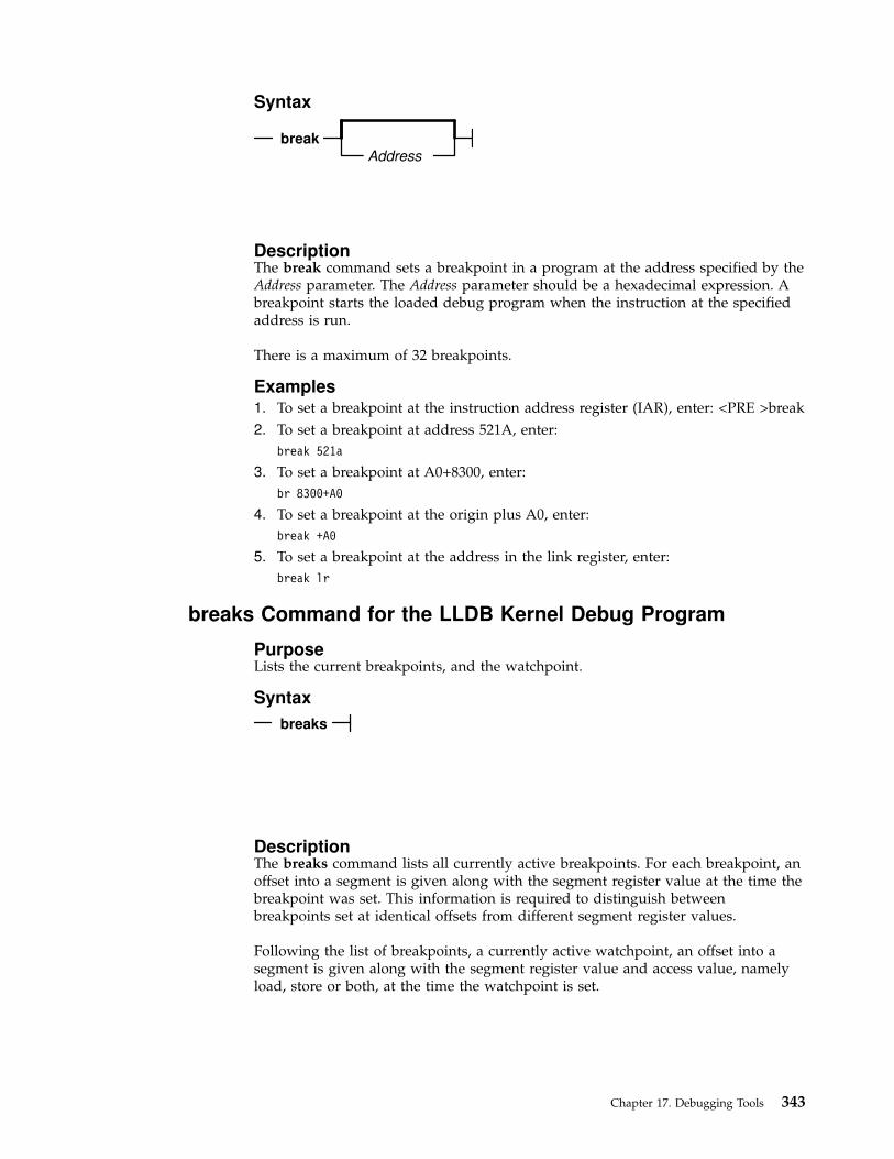
Syntax
breakAddress
DescriptionThe break command sets a breakpoint in a program at the address specified by theAddress parameter. The Address parameter should be a hexadecimal expression. Abreakpoint starts the loaded debug program when the instruction at the specifiedaddress is run.
There is a maximum of 32 breakpoints.
Examples1. To set a breakpoint at the instruction address register (IAR), enter: <PRE >break
2. To set a breakpoint at address 521A, enter:
break 521a
3. To set a breakpoint at A0+8300, enter:
br 8300+A0
4. To set a breakpoint at the origin plus A0, enter:
break +A0
5. To set a breakpoint at the address in the link register, enter:
break lr
breaks Command for the LLDB Kernel Debug Program
PurposeLists the current breakpoints, and the watchpoint.
Syntax
breaks
DescriptionThe breaks command lists all currently active breakpoints. For each breakpoint, anoffset into a segment is given along with the segment register value at the time thebreakpoint was set. This information is required to distinguish betweenbreakpoints set at identical offsets from different segment register values.
Following the list of breakpoints, a currently active watchpoint, an offset into asegment is given along with the segment register value and access value, namelyload, store or both, at the time the watchpoint is set.
Chapter 17. Debugging Tools 343
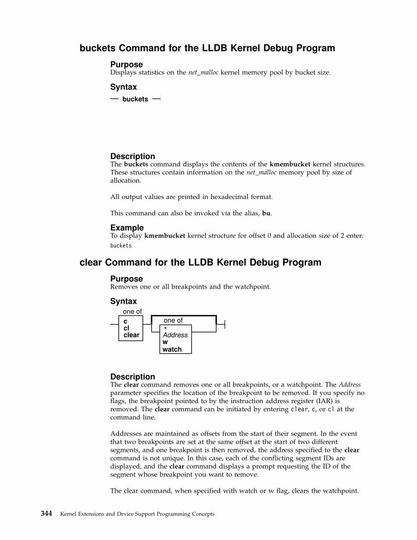
buckets Command for the LLDB Kernel Debug Program
PurposeDisplays statistics on the net_malloc kernel memory pool by bucket size.
Syntax
buckets
DescriptionThe buckets command displays the contents of the kmembucket kernel structures.These structures contain information on the net_malloc memory pool by size ofallocation.
All output values are printed in hexadecimal format.
This command can also be invoked via the alias, bu.
ExampleTo display kmembucket kernel structure for offset 0 and allocation size of 2 enter:
buckets
clear Command for the LLDB Kernel Debug Program
PurposeRemoves one or all breakpoints and the watchpoint.
Syntax
cclclear
one of
one of
*
wwatch
Address
DescriptionThe clear command removes one or all breakpoints, or a watchpoint. The Addressparameter specifies the location of the breakpoint to be removed. If you specify noflags, the breakpoint pointed to by the instruction address register (IAR) isremoved. The clear command can be initiated by entering clear, c, or cl at thecommand line.
Addresses are maintained as offsets from the start of their segment. In the eventthat two breakpoints are set at the same offset at the start of two differentsegments, and one breakpoint is then removed, the address specified to the clearcommand is not unique. In this case, each of the conflicting segment IDs aredisplayed, and the clear command displays a prompt requesting the ID of thesegment whose breakpoint you want to remove.
The clear command, when specified with watch or w flag, clears the watchpoint.
344 Kernel Extensions and Device Support Programming Concepts

Examples1. To clear the breakpoint at the IAR, enter:
clear
2. To clear the breakpoint at the 10000200 address, enter:
cl 10000200
3. To clear all breakpoints, enter:
clear *
4. To clear the watchpoint, enter:
clear w
cpu Command for the LLDB Kernel Debug Program
PurposeSwitches the current processor, and reports the kernel debug state of processors.
Syntax
cpuProcessorNumber
DescriptionThe cpu command places the processor specified by the ProcessorNumber parameterin debug mode; the processor enters the debugger and is ready to acceptcommands. The processor where the debugger was previously running is stopped.This command is available only on multiprocessor systems.
If no processor is specified, the cpu command displays the kernel debug state ofeach processor. The possible states are as follows:
Debug The processor has entered the debugger.
Stopped The processor has been stopped by another processor in the debug state.
Waiting The processor has hit a breakpoint while another processor is in the debugstate, without having been stopped by the other processor. A particularexample is the race condition where two processors both hit breakpoints.One of the processors will enter the debug state; the other will enter thewaiting state.
ExampleTo select the first processor, enter:
cpu 0
display Command for the LLDB Kernel Debug Program
PurposeDisplays a specified amount of memory.
Chapter 17. Debugging Tools 345

Syntax
display AddressLength
DescriptionThe display command displays memory storage, starting at the address specifiedby the Address parameter. The Length parameter indicates the number of bytes todisplay, and has a default value of 16.
The display command displays the contents of the specified region of memory in atwo-column format. The left column displays the contents of memory inhexadecimal, and the right column displays the printable ASCII representation ofthe hexadecimal data.
The display command also shows the exact amount of storage requested when youspecify a length of 1, 2, or 4 bytes. In this instance, it uses the processor loadcharacter, load halfword, or load fullword instruction, respectively. Theseinstructions should be used when displaying input and output address space. Anyother value for the Length parameter causes memory to be loaded one byte at atime.
Examples1. To display 16 bytes at the IAR, enter:
display iar
2. To display 12 bytes at address 152F, enter:
d 152F 12
3. To display 16 bytes at the origin + B7, enter:
display +B7
4. To display 16 bytes at the address in r3, enter:
disp r3
5. To display from the address contained in the address in r3, enter:
d r3>
dmodsw Command for the LLDB Kernel Debug Program
PurposeDisplays the internal STREAMS driver switch table.
Syntax
dmodsw
DescriptionThe dmodsw command displays the internal STREAMS driver switch table, oneentry at a time. By pressing the Enter key, you can walk through all the dmodsw
346 Kernel Extensions and Device Support Programming Concepts
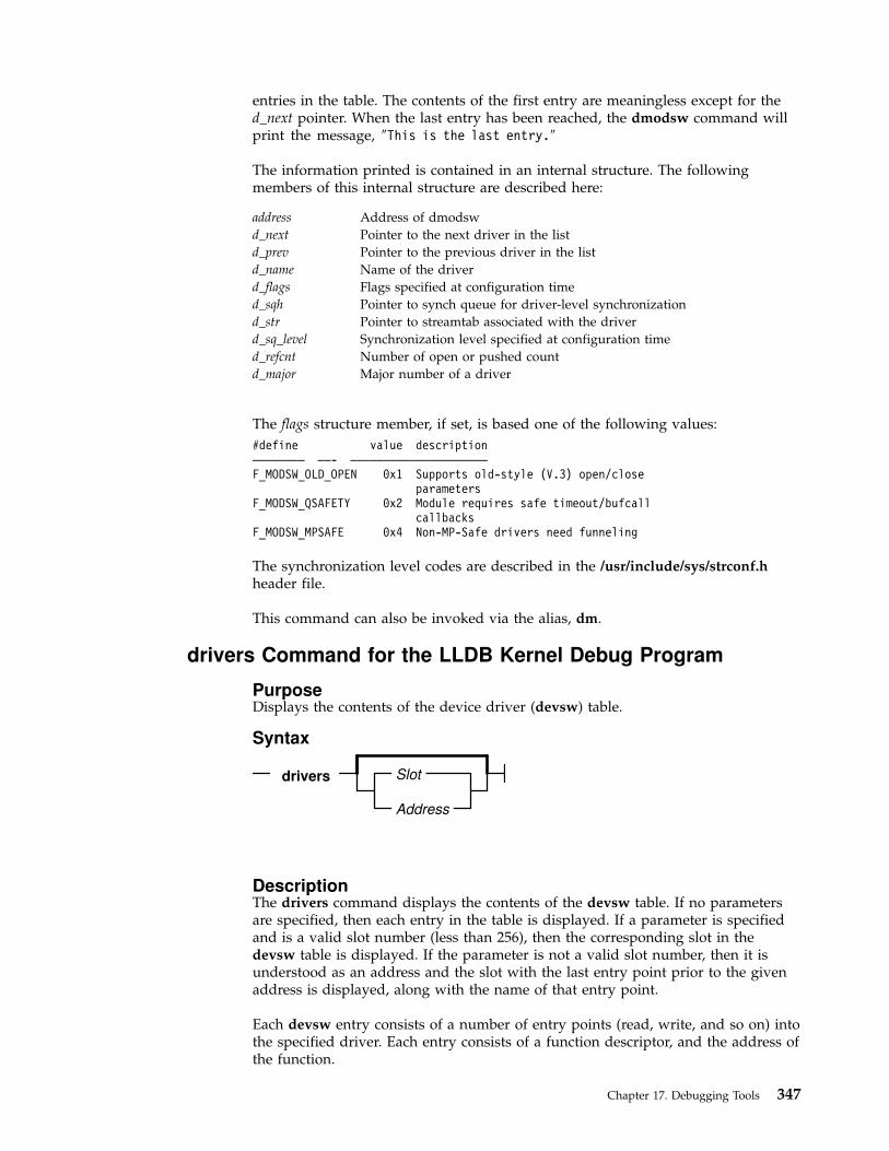
entries in the table. The contents of the first entry are meaningless except for thed_next pointer. When the last entry has been reached, the dmodsw command willprint the message, ″This is the last entry.″
The information printed is contained in an internal structure. The followingmembers of this internal structure are described here:
address Address of dmodsw
d_next Pointer to the next driver in the list
d_prev Pointer to the previous driver in the list
d_name Name of the driver
d_flags Flags specified at configuration time
d_sqh Pointer to synch queue for driver-level synchronization
d_str Pointer to streamtab associated with the driver
d_sq_level Synchronization level specified at configuration time
d_refcnt Number of open or pushed count
d_major Major number of a driver
The flags structure member, if set, is based one of the following values:
#define value description———————— ——- —————————————————————
F_MODSW_OLD_OPEN 0x1 Supports old-style (V.3) open/closeparameters
F_MODSW_QSAFETY 0x2 Module requires safe timeout/bufcallcallbacks
F_MODSW_MPSAFE 0x4 Non-MP-Safe drivers need funneling
The synchronization level codes are described in the /usr/include/sys/strconf.hheader file.
This command can also be invoked via the alias, dm.
drivers Command for the LLDB Kernel Debug Program
PurposeDisplays the contents of the device driver (devsw) table.
Syntax
drivers
Address
Slot
DescriptionThe drivers command displays the contents of the devsw table. If no parametersare specified, then each entry in the table is displayed. If a parameter is specifiedand is a valid slot number (less than 256), then the corresponding slot in thedevsw table is displayed. If the parameter is not a valid slot number, then it isunderstood as an address and the slot with the last entry point prior to the givenaddress is displayed, along with the name of that entry point.
Each devsw entry consists of a number of entry points (read, write, and so on) intothe specified driver. Each entry consists of a function descriptor, and the address ofthe function.
Chapter 17. Debugging Tools 347

Examples1. To display the entire devsw table, enter:
drivers
2. To display the tenth slot of the devsw table, enter:
drivers 10
3. To display the last entry point before the address 0x130000F, enter:
dr 130000f
find Command for the LLDB Kernel Debug Program
PurposeSearches storage.
Syntax
DescriptionThe find command searches storage for a pattern beginning at the addressspecified by the Address parameter. If the specified argument is found, the searchstops and storage containing the specified argument is displayed. The address ofthe storage is placed into the fx variable.
The following defaults apply to the first execution of the find command:
v Address = 0
v EndAddress = 0x0FFFFFFFFFFFFFFF (for 64-bit process)
v EndAddress = 0xFFFFFFFF (for 32-bit process)
v Alignment = 1 (byte alignment)
An asterisk (*) can be substituted for any of the parameters. An asterisk causes thefind command to use the value for that parameter that was used in the previousexecution of the command.
Examples1. To find the first occurrence of 7c81 in virtual memory starting at 0, enter:
find 7c81
2. To find the first occurrence of the string TEST, enter:
find "TEST"
3. To find the first occurrence of 7c81 after address 10000, enter:
f 7c81 10000
4. To find the first occurrence of 7c81 between 0 and the user-defined topvariable, enter:
f 7c81 0 top
5. To find the first occurrence of 7c81 starting at the last address used, enter:
find 7c81 *
6. To find the first of occurrence of 7c81 starting at the last address used andaligned on a halfword, enter:
f 7c81 * * 2
348 Kernel Extensions and Device Support Programming Concepts

7. To find the next occurrence of 7c starting at 1 plus the last address at which thefind command stopped, enter:
f 7c fx+1 * 2
8. To search for the last pattern used, enter:
find *
9. To search for the last pattern starting at the next location (the find commandremembers the alignment which was used in the previous search), enter:
f * fx+1
float Command for the LLDB Kernel Debug Program
PurposeDisplays floating-point registers.
Syntax
float
DescriptionThe float command displays the contents of floating-point registers and othercontrol registers.
In a 64-bit context, the segment register contents will not be displayed.
fmodsw Command for the LLDB Kernel Debug Program
PurposeDisplays the internal STREAMS module switch table.
Syntax
fmodsw
DescriptionThe fmodsw command displays the internal STREAMS module switch table, oneentry at a time. By pressing the Enter key, you can walk through all the fmodswentries in the table. The contents of the first entry are meaningless except for thed_next pointer. When the last entry has been reached, the fmodsw command willprint the message This is the last entry. This command can also be invoked viathe alias, fm.
The information printed is contained in an internal structure. The followingmembers of this internal structure are described here:
address Address of fmodsw
d_next Pointer to the next module in the list
Chapter 17. Debugging Tools 349
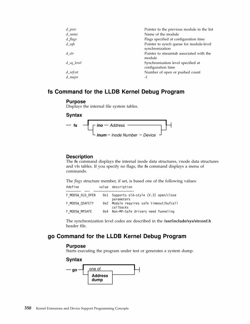
d_prev Pointer to the previous module in the list
d_name Name of the module
d_flags Flags specified at configuration time
d_sqh Pointer to synch queue for module-levelsynchronization
d_str Pointer to streamtab associated with themodule
d_sq_level Synchronization level specified atconfiguration time
d_refcnt Number of open or pushed count
d_major -1
fs Command for the LLDB Kernel Debug Program
PurposeDisplays the internal file system tables.
Syntax
fs ino Address
inum Inode Number Device
DescriptionThe fs command displays the internal inode data structures, vnode data structuresand vfs tables. If you specify no flags, the fs command displays a menu ofcommands.
The flags structure member, if set, is based one of the following values:
#define value description———————— ——- —————————————————————-F_MODSW_OLD_OPEN 0x1 Supports old-style (V.3) open/close
parametersF_MODSW_QSAFETY 0x2 Module requires safe timeout/bufcall
callbacksF_MODSW_MPSAFE 0x4 Non-MP-Safe drivers need funneling
The synchronization level codes are described in the /usr/include/sys/strconf.hheader file.
go Command for the LLDB Kernel Debug Program
PurposeStarts executing the program under test or generates a system dump.
Syntax
Addressdump
one ofgo
350 Kernel Extensions and Device Support Programming Concepts
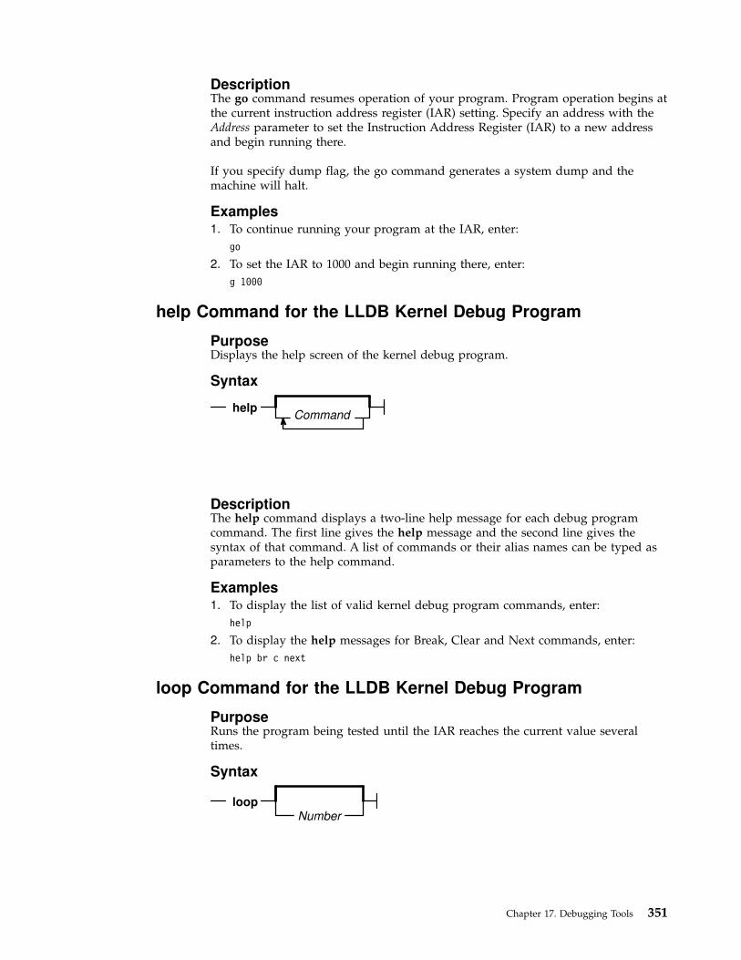
DescriptionThe go command resumes operation of your program. Program operation begins atthe current instruction address register (IAR) setting. Specify an address with theAddress parameter to set the Instruction Address Register (IAR) to a new addressand begin running there.
If you specify dump flag, the go command generates a system dump and themachine will halt.
Examples1. To continue running your program at the IAR, enter:
go
2. To set the IAR to 1000 and begin running there, enter:
g 1000
help Command for the LLDB Kernel Debug Program
PurposeDisplays the help screen of the kernel debug program.
Syntax
Commandhelp
DescriptionThe help command displays a two-line help message for each debug programcommand. The first line gives the help message and the second line gives thesyntax of that command. A list of commands or their alias names can be typed asparameters to the help command.
Examples1. To display the list of valid kernel debug program commands, enter:
help
2. To display the help messages for Break, Clear and Next commands, enter:
help br c next
loop Command for the LLDB Kernel Debug Program
PurposeRuns the program being tested until the IAR reaches the current value severaltimes.
Syntax
Numberloop
Chapter 17. Debugging Tools 351

DescriptionThe loop command causes the system to continue running and to stop when theinstruction address register (IAR) returns to the current value the number of timesspecified by the Number parameter. All other breakpoints are ignored. The Numberparameter specifies the number of loops that execute before the debug programregains control, and must be a valid decimal expression. The default value for theNumber parameter is 1.
The loop command is similar to setting a breakpoint at the current IAR, but allowsyou to stop on a specified instance when the IAR returns to the current point.
ExampleTo execute until the second time the IAR has the current value, enter:
loop 2
map Command for the LLDB Kernel Debug Program
PurposeDisplays the system load list.
Syntax
map Address
SymbolName
DescriptionThe map command displays information from the system load list. The systemload list is the list of symbols exported from the kernel. If the map command isentered with no parameters, then the entire load list is displayed one page at atime. If an address is given, the name and value of the last symbol located beforethe given address is displayed. If a symbol name is given, then the load list issearched for the symbol and any matching entries are displayed. There can bemore than one entry for a given symbol table.
Since the load list contains only symbols exported from the kernel, a given symbolname can be in the kernel but not reported by the map command.
The symbol value for a data structure is the address of that data structure. Thesymbol value for a function is not the address of the function, but the address ofthe function descriptor. The first word of the function descriptor is the address ofthe function. For example, if entering map execexit displays 0x1000, then enteringdisplay 1000 displays the address of the execexit function in the first word of thedisplayed memory.
Examples1. To display the entire load list, enter:
map
2. To display the symbol with a value closest to 0xe3000000, enter:
m e3000000
3. To display the value of the function execexit, enter:
map execexit
352 Kernel Extensions and Device Support Programming Concepts

mblk Command for the LLDB Kernel Debug Program
PurposeDisplays the contents of the STREAMS message blocks defined by the msgbstructure in the /usr/include/sys/stream.h header file.
Syntax
Addressmblk
DescriptionThe mblk command displays the contents of the msgb structure that is defined inthe /usr/include/sys/stream.h headerfile. If you do not specify an Address, thecommand displays the contents of the message blocks of type M_MBLK andM_MBDATA, as well as displays the address of mh_freelater.
The mh_freelater parameter is a pointer to the message blocks that are just nowfreed and are scheduled to be given back to the system, but are not yet given back.
All output values are printed in hexadecimal format.
This command can also be invoked via the alias, mb.
Examples1. To display the contents of the message blocks of type M_BLK and
M_MBDATA, and the address of mh_freelater, enter:
mblk
2. To display the contents of the message block structure at address 0005ec80,enter:
mblk 0005ec80
mst64 Command for the LLDB Kernel Debug Program
PurposeDisplays the mstsave64 structure of a 64-bit process. It also displays the kernelremap structure containing all the remapped 64-bit user addresses.
Syntax
Thread IDmst64
DescriptionThe mst64 command displays the mstsave64 structure if you specify the thread idof any thread of a 64-bit process. With no parameter specified, the mstsave64structure of the currently active thread of a 64-bit process is displayed. In addition,the kernel remap structure containing all the remapped 64-bit user addresses aredisplayed.
Chapter 17. Debugging Tools 353

ExampleTo display mstsave64 structure of a thread of a 64-bit process with thread id 205,enter:
mst64 205
netdata Command for the LLDB Kernel Debug Program
PurposeDisplays the mbuf, ndd, socket, inpcb and tcpcb data structures.
Syntax
netdata
DescriptionThe netdata or net command displays a menu of options to display one of thembuf, ndd, socket, inpcb and tcpcb data structures, at the specified address.
next Command for the LLDB Kernel Debug Program
PurposeIncreases the instruction address register (IAR).
Syntax
Numbernext
DescriptionThe next command increases the instruction address register (IAR) by the numberspecified by the Number parameter and displays the new current instruction. Thedefault value for the Number parameter is 4 bytes.
Examples1. To increment the IAR by 4 bytes, enter:
next
2. To increment the IAR by 20 bytes, enter:
n 20
origin Command for the LLDB Kernel Debug Program
PurposeSets the address origin of the instruction address register (IAR).
354 Kernel Extensions and Device Support Programming Concepts

Syntax
origin Number
DescriptionThe origin command sets the address origin. The origin address specified by theNumber parameter is added to any hexadecimal expression beginning with a +(plus sign). This command is especially useful when setting breakpoints. Use thescreen command to display the value of the origin and the origin displacement ofthe IAR.
The origin command also sets the reserved org variable. For example, enteringorigin 652C0 does the same as entering set org 652C0.
Examples1. To set the origin to 178D, enter:
origin 178D
2. To set the origin to 59cc, enter:
o 59cc
ppd Command for the LLDB Kernel Debug Program
PurposeDisplays per-processor data.
Syntax
ProcessorNumber
ppd
DescriptionThe ppd command displays the per-processor data structure of the specifiedprocessor. If no argument is given, data for the current processor, as selected by thecpu command, is displayed.
Note: The ppd command is available only on multiprocessor systems.
Examples1. To display per-processor data for the current processor, enter:
ppd
2. To display per-processor data for processor 2, enter:
ppd 2
proc Command for the LLDB Kernel Debug Program
PurposeDisplays the formatted process table.
Chapter 17. Debugging Tools 355
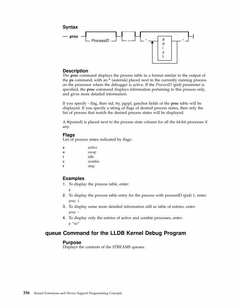
Syntax
ProcessID ”proc
aoizt
”–
DescriptionThe proc command displays the process table in a format similar to the output ofthe ps command, with an * (asterisk) placed next to the currently running processon the processor where the debugger is active. If the ProcessID (pid) parameter isspecified, the proc command displays information pertaining to this process only,and gives more detailed information.
If you specify - flag, then sid, tty, pgrpl, ganchor fields of the proc table will bedisplayed. If you specify a string of flags of desired process states, then only thelist of process that match the desired process states will be displayed.
A #(pound) is placed next to the process state column for all the 64-bit processes ifany.
FlagsList of process states indicated by flags:
a active
o swap
i idle
z zombie
t stop
Examples1. To display the process table, enter:
p
2. To display the process table entry for the process with processID (pid) 1, enter:
proc 1
3. To display some more detailed information still as table of entries, enter:
proc -
4. To display only the entries of active and zombie processes, enter:
p "az"
queue Command for the LLDB Kernel Debug Program
PurposeDisplays the contents of the STREAMS queues.
356 Kernel Extensions and Device Support Programming Concepts

Syntax
queue Address
DescriptionThe queue command displays the contents of the STREAMS queue at the specifiedAddress. Refer to the /usr/include/sys/stream.h header file for the queue structuredefinition.
In the output, an X indicates that the value is printed in hexadecimal format.
This command can also be invoked via the alias, que.
ExampleTo display the contents of the STREAMS queue stored at address 59c1874, where59c1874 is a valid queue address, enter:
queue 59c1874
quit Command for the LLDB Kernel Debug Program
PurposeEnds the debug program session.
Syntax
quitdump
DescriptionThe quit command terminates the debug session. Use this command when youhave completed debugging and want to clear all breakpoints. The quit commandperforms the following tasks:
v Clears all breakpoints, and the watchpoint
v Issues the go command.
If you specify dump flag, the quit command generates a system dump and themachine will halt.
To use the debug program again after issuing the quit command, use one of thekeyboard sequences described in “Entering the LLDB Kernel Debug Program” onpage 334.
reason Command for the LLDB Kernel Debug Program
PurposeDisplays the reason for entering the debugger.
Chapter 17. Debugging Tools 357

Syntax
reason
DescriptionThe reason command displays the actual reason why the debugger was entered.
reboot Command for the LLDB Kernel Debug Program
PurposeReboots the machine.
Syntax
reboot
DescriptionThe reboot command reboots the system, after getting confirmation from the userby an input prompt.
Note: The system cannot be rebooted using this command at boot-timedebugger prompt.
reset Command for the LLDB Kernel Debug Program
PurposeClears a user-defined variable.
Syntax
reset VariableName
DescriptionThe reset command clears those variables specified with the VariableNameparameter. Resetting a variable effectively deletes it, and allows the variable slot tobe used again. Currently, 16 user-defined variables are allowed, and when they areall in use, you cannot set any more. Use the vars command to display all variablescurrently set.
Variables that are not user-defined, such as registers, cannot be reset. If you specifya variable that is not user-defined, or a variable that is not defined, an errormessage is displayed.
358 Kernel Extensions and Device Support Programming Concepts

ExampleTo delete the user-defined variable foo, enter:
reset foo
screen Command for the LLDB Kernel Debug Program
PurposeDisplays a screen of data.
Syntax
+–trackonoffon half
Address
screen one of
VariableName
DescriptionThe screen command primarily displays memory and registers, but it is also usedto control the format of subsequent screen commands. By default, memory isdisplayed starting at the instruction address register (IAR), or at the variablecurrently tracked. Variables can be tracked by specifying them with the trackVariableName flag.
The track option changes the address that the screen displays as the expressionthat is being tracked changes. This option is useful in a case where, at abreakpoint, the memory to be displayed is addressed by a register.
You can also use parameters to modify the format of the screen so that only half ofthe physical screen is used, or even turn off the screen display entirely. The formatmodification parameters are useful if important information can be scrolled off thescreen when the debugger is entered. Restore the default (full) screen by entering:
screen on
In 64-bit context, the screen command displays 64-bit wide GPRs and other controlregisters that exist only on 64-bit hardware. The memory display is limited. Allscreen operations remain same as before.
Flags
+ Displays the next 0x70 bytes of data.
- Displays the previous 0x70 bytes of data.
track VariableName Instructs the screen display to track to the specified variable.
on Turns the display on.
off Turns the display off so that the screen display does not appearwhen the debug program is started. This flag is useful if aslow, asynchronous terminal is used.
on half Displays only the top half of the display screen. The memorydisplay is omitted.
Chapter 17. Debugging Tools 359

Examples1. To display the next 112 bytes of data, enter:
screen +
2. To display the previous 112 bytes of data, enter:
screen -
3. To display memory starting at 20000FF7, enter:
s 20000ff7
4. To display memory at the address contained in location 200, enter:
s 200>
5. To turn on the display, enter:
screen on
6. To turn off the display, enter:
screen off
7. To set the display format to use about half of the screen, enter:
screen on half
8. To track memory starting at the value in general purpose register 3, enter:
sc track r3
segst64 Command for the LLDB Kernel Debug Program
PurposeDisplays the states of all memory segments of a 64-bit process.
Syntax
FilenoShmptrSrvalattr
Segflag
one of
–s
segst64Esid (segment register)
DescriptionThe segst64 command displays the states of all the segments starting from thespecified Esid (segment register). You can also specify Segflag parameter, with astring to identify the type of the segment (SEG_AVAIL_, SEG_MAPPED, etc.) andoptionally either fileno or pointer to shared memory segment or srval, or segmentattribute (attr) to uniquely locate the segment you are looking for. You will beprompted to specify ProcessID (pid) of a 64-bit process. You will also be promptedto specify starting Esid (segment register) if you do not specify it as a parameter.The currently active 64-bit process’s ProcessID (pid) with starting register value of3 would be the default. If no parameter was specified, the segst64 commanddisplays states of all the segments of the currently active 64-bit process startingfrom segment register value 3.
Examples1. To display the states of all the segments of the currently active 64-bit process
starting from Esid (segment register) value 3.
segst64
360 Kernel Extensions and Device Support Programming Concepts

2. You will be prompted to specify the ProcessID (pid) and Esid (segmentregister). Press the Enter key at the prompt if you want to accept the defaultvalues.
3. To display states of all the segments in SEG_AVAIL, state, of the currentlyactive 64-bit process starting from Esid (segment register) value 3, enter:
seget64 -s "SEG_AVAIL"
You will be prompted to specify the ProcessID (pid) and Esid (segmentregister). Press the Enter key at the prompt if you want to accept the defaultvalues.
4. To display states of all the segments in SEG_MAPPED state with fileno value of1, of the currently active 64-bit process starting from Esid (segment register)value 3, enter:
seg -s "SEG_MAPPED" 1
You will be prompted to specify the ProcessID (pid) and Esid (segmentregister). Press the Enter key at the prompt if you want to accept the defaultvalues.
5. To display the states of all the segments of the currently active 64-bit processstarting from Esid (segment register) value 257, enter:
segst64 257
You will be prompted to specify the ProcessID (pid). Press the Enter key at theprompt if you want to accept the default value.
set Command for the LLDB Kernel Debug Program
PurposeCreate and change values of debugger variables.
Syntax
set
Register
ValueVariable
DescriptionThis command sets debugger variables. Use the set command to create newvariables or modify the value of old variables. Certain debugger variables aresymbolic names for machine registers, which you can modify. See “ReservedVariables” on page 336 for a list of these variables.
An additional debugger variable asr has been introduced in AIX4.3. Also, in 64-bitcontext, you can set segment register values to all the possible segment registersranging from 0 to FFFFFFFF, using a debugger variable sx<nnnnnnnn> (i.e., sxfollowed by segment register number). In 64-bit context, the segment registers areemulated in memory. An error message will be displayed if the assignment to thememory location is paged out.
The sr64 subcommand could be used to verify the srval just set to thesx<nnnnnnnn>register.
Chapter 17. Debugging Tools 361
Note: The reset command cannot be used to release the sxnnnnnnnndebugger variable.
Examples1. To assign value 100 to variable start.
set start 100
2. To set general purpose register 12 to 0.
set r12 0
3. To set segment register 3 to 10000.
se s3 10000
4. To assign 45F0 to the Iar.
set iar 45F0
5. To assign string ″AIX″ to variable name.
se name "AIX"
6. To set segment register 257 to 10000
set sx257 10000
sregs Command for the LLDB Kernel Debug Program
PurposeDisplays segment registers all times except in 64-bit context.
Syntax
sregs
DescriptionThe sregs command displays the contents of the segment registers and othercontrol registers. The display created is similar to that created by the screencommand (see “screen Command for the LLDB Kernel Debug Program” onpage 359).
The screen display format changes in 64-bit context. If the debugger is in 64-bitcontext, then the segment registers will not be displayed. All GPRs and othercontrol registers with 64-bits wide contents will be displayed.
Note: sr64 command must be used to look at the contents of the segmentregisters for a 64-bit process.
sr64 Command for the LLDB Kernel Debug Program
PurposeDisplays segment registers only in 64-bit context.
362 Kernel Extensions and Device Support Programming Concepts

Syntax
ProcessID–p
sr64
Esid
Size
DescriptionThe sr64 command displays all the segment register values of a 64-bit processspecified by a ProcessID (pid) parameter starting from specified Esid (segmentregister) parameter. The default Pid value process would be that of the currentlyactive 64-bit process and the default Esid value would be zero. An error messagewill be displayed if either the specified process or the default currently activeprocess is not a 64-bit process.
Examples1. To display the segment registers of currently active 64-bit process, starting from
esid (segment register number) 257, enter:
sr64
2. To display the segment registers of a 64-bit process of pid 204, starting fromEsid (segment register number) zero, enter:
sr64 -p 204
3. To display the segment registers of a 64-bit process of pid 204, starting fromEsid (segment register number) 257, enter:
sr64 -p 204 257
st Command for the LLDB Kernel Debug Program
PurposeStores a fullword into memory.
Syntax
Addressst Data
DescriptionThe st command stores a fullword of data into memory by using the processorfullword store instruction. If the address specified by the Address parameter is notword-aligned, it is rounded down to a fullword. The st command is the correctway to place a fullword of data into input and output memory.
This is similar to the alter command, but the word size is implicit in the command.stc and sth are used to perform similar functions for bytes and halfwords.
ExampleTo store the 32-bit value 5 at address 1000, enter:
st 1000 5
Chapter 17. Debugging Tools 363

stack Command for the LLDB Kernel Debug Program
PurposeDisplays a formatted stack traceback.
Syntax
stackThreadID
DescriptionThe stack command displays a formatted kernel-stack traceback for the specifiedkernel thread. If no thread is specified, the currently running thread is used. Stackframes show return addresses and can be used to trace the calling sequence of theprogram. Be aware that the first few parameters are passed in registers to thecalled functions, and are not usually available on the stack. Generally only thestack chain (stacks back-chain pointer) and return address (address where thecurrent function returns upon completion) are valid. To interpret the stackthoroughly, it is necessary to use an assembler language listing for a procedure todetermine what has been stored on the stack. Stack frames for the specified threadare not always accessible.
Examples1. To format any existing stack frames, enter:
stack
2. To format stack frames for the thread with thread ID 251 enter:
sta 251
stc Command for the LLDB Kernel Debug Program
PurposeStores one byte into memory.
Syntax
Addressstc Data
DescriptionThe stc command stores a byte of data specified by the Data parameter intomemory at the address specified by the Address parameter by using the processorstore-character instruction. The stc command is the correct way to place a byte ofdata into input and output memory.
This is similar to the st and sth commands, which are used for fullwords andhalfwords.
364 Kernel Extensions and Device Support Programming Concepts

ExampleTo store the 8-bit value FF at address 1000, enter:
stc 1000 ff
step Command for the LLDB Kernel Debug Program
PurposeRuns instructions single-step.
Syntax
step
s
Number
DescriptionThe step command causes the processor to enter a single instruction and returncontrol to the debug program. If a branch is the next instruction to be run, the sflag causes the processor to step over a subroutine call. An integer Numberparameter is used as the number of instructions to run before returning control tothe debug program.
Note: On multiprocessor systems, other processors are not released duringstep, contrary to most commands.
Flag
s Executes a subroutine as if it were one instruction.
Examples1. To single step the processor, enter:
step
2. To single step and skip over a subroutine call, enter:
step s
3. To step for 20 instructions, enter:
step 20
sth Command for the LLDB Kernel Debug Program
PurposeStores a halfword into memory.
Syntax
Addresssth Data
Chapter 17. Debugging Tools 365
DescriptionThe sth command stores a halfword of data specified by the Data parameter intomemory by using the processor store halfword instruction. If the address specifiedby the Address parameter is not halfword-aligned, it is rounded down to ahalfword boundary. The sth command is the correct way to place a halfword intoinput and output memory space.
This is similar to the st and stc commands, which are used for fullwords andbytes.
ExampleTo store the 16-bit value 14 at address 1000, enter:
sth 1000 0014
stream Command for the LLDB Kernel Debug Program
PurposeDisplays the contents of the stream head table.
Syntax
streamAddress
DescriptionThe stream command displays the contents of the stream head table. If no addressis specified, the command displays the first stream found in the STREAMS hashtable. If the address is specified, the command displays the contents of the streamhead stored at that address.
The information printed is contained in an internal structure. The followingmembers of this internal structure are described here:
sth address of stream head
wq address of streams write queue
rq address of streams read queue
dev associated device number of the stream
read_mode read mode
write_mode write mode
close_wait_timeout close wait timeout in microseconds
read_error read error on the stream
write_error write error on the stream
flags stream head flag values
push_cnt number of modules pushed on the stream
wroff write offset to prepend M_DATA
ioc_id id of outstanding M_IOCTL request
ioc_mp outstanding ioctl message
next next stream head on the link
pollq list of active polls
sigsq list of active M_SETSIGs
shttyp pointer to tty information
366 Kernel Extensions and Device Support Programming Concepts

The read_mode and write_mode values are defined in the /usr/include/sys/stropts.hheader file.
The read_error and write_error variables are integers defined in the/usr/include/sys/errno.h header file.
The flags structure member, if set, is based on combinations of the followingvalues:
#define Value Description
F_STH_READ_ERROR 0x0001 M_ERROR with read errorreceived, fail all read calls.
F_STH_WRITE_ERROR 0x0002 M_ERROR with write errorreceived, fail all writes.
F_STH_HANGUP 0x0004 M_HANGUP received, nomore data.
F_STH_NDELON 0x0008 Do TTY semantics forONDELAY handling.
F_STH_ISATTY 0x0010 This stream acts a terminal.
F_STH_MREADON 0x0020 Generate M_READ messages.
F_STH_TOSTOP 0x0040 Disallow background writes(for job control).
F_STH_PIPE 0x0080 Stream is one end of a pipeor FIFO.
F_STH_WPIPE 0x0100 Stream is the ″write″ side ofa pipe.
F_STH_FIFO 0x0200 Stream is a FIFO.
F_STH_LINKED 0x0400 Stream has one or morelower streams linked.
F_STH_CTTY 0x0800 Stream controlling tty.
F_STH_CLOSED 0x4000 Stream has been closed, andshould be freed.
F_STH_CLOSING 0x8000 Actively on the way down.
In the output, values marked with X are printed in hexadecimal format.
This command can also be invoked via the alias, str.
Examples1. To display the first stream head found in the stream head table, enter:
stream
2. To display the contents of the particular stream head located at address 59b2e00(where 59b2e00 is a valid stream head address), enter:
stream 59b2e00
swap Command for the LLDB Kernel Debug Program
PurposeSwitches to the specified RS-232 port.
Chapter 17. Debugging Tools 367
Syntax
Portswap
DescriptionThe swap command allows control of the debug program to be transferred toanother terminal. The Port parameter specifies which asynchronous tty port totransfer control. The swap command does not support returning to a port that waspreviously used.
Specify 0 for port 0 (s1) or 1 for port 1 (s2).
Ports must be configured the same as the port on which the debug program iscurrently running: 9600 baud, 8 data bits, no parity. The device attached to the portmust respond with a carrier detect within 1/10 seconds or the command fails andcontrol will not be transferred.
ExampleTo switch display to RS-232 port 1, enter:
swap 1
sysinfo Command for the LLDB Kernel Debug Program
PurposeDisplays the system configuration information.
Syntax
sysinfo
DescriptionThe sysinfo command displays the system configuration information such as themodel, architecture and more details.
thread Command for the LLDB Kernel Debug Program
PurposeDisplays thread table entries.
368 Kernel Extensions and Device Support Programming Concepts

Syntax
”?iorstz
”thread
ProcessIDThreadID
one of
DescriptionThe thread command displays the contents of the kernel thread table. If theProcessID (pid) parameter is given, information about all kernel threads belongingto that process is displayed. If the ThreadID parameter is given, detailedinformation about the specified kernel thread is displayed. If no parameters aregiven, information about all kernel threads in the kernel thread table is displayed.Note that the ProcessID (pid) and ThreadID parameters share a common namespace: even numbers are always used for ProcessIDs, whereas odd numbers areused for threads (the init processes, PID 1, is an exception).
If you specify a string of flags of desired thread states, then only the list of threadsthat match the desired threads states will be displayed.
FlagsList of process states indicated by flags:
i idle
o swap
r runnable
s sleep
t stop
z zombie
Examples1. To display information about all threads in the thread table, enter:
thread
The output is similar to:
SLT ST TID PID CPUID POLICY PRI CPU EVENTPROCNAME FLAGS
0 s 3 0 ANY OTHER 10 78 swapper 0x000014001 s 103 1 ANY OTHER 3C 0 init 0x000004002*r 205 204 0 OTHER 7F 78 wait 0x000010003 r 307 306 1 OTHER 7F 78 wait 0x000010004 s 409 408 ANY OTHER 24 0 netm 0x000010005 s 50B 50A ANY OTHER 24 0 gil 0x00001000
6 s 60D 50A ANY OTHER 24 0 000B2DA8 gil 0x000010007 s 70F 50A ANY OTHER 24 0 000B2DA8 gil 0x000010008 s 811 50A ANY OTHER 24 0 000B2DA8 gil 0x000010009 s 913 50A ANY OTHER 24 1 000B2DA8 gil 0x00001000
10 s A15 60C ANY OTHER 3C 0 sh 0x0000040011 s B17 70E ANY OTHER 3C 0 sh 0x00000400
2. To display information about the threads in process 2106, enter:
Chapter 17. Debugging Tools 369

th 2106
3. To display information about the thread with thread ID 1497, enter:
th 1497
4. To display only the entries of sleeping and zombie threads, enter:
th "sz"
Note: All the flags must be entered as a single string.
trace Command for the LLDB Kernel Debug Program
PurposeDisplays formatted kernel trace buffers.
Syntax
: SubhookID
–c–h
HookIDtrace
Channel
DescriptionThe trace command displays the last 128 entries of a kernel trace buffer in reversechronological order. There are 8 trace buffers, each associated with a trace channel.Each can trace any combination of trace events. Trace data gives an indication ofsystem activity at a very low level; interrupts, input/output, and processscheduling are examples of event types that can be traced.
The trace command displays headers for the trace buffers that contain pointers intothe trace buffers and the state of the trace driver. Following this are the last 128entries from the selected trace buffer. Trace entries consist of a major and a minornumber for the trace hook, an ASCII trace ID, an ASCII trace hook type, followedby either a hexadecimal dump of the trace data or a pointer to the start of avariable-length block of trace data.
The trace command is not meant to replace the trcfmt command, which formatsthe trace data in more detail. It is a facility for viewing system trace data in theevent of a system crash before the data has been written to disk.
Flags
-c Channel Specifies the trace channel used.
-h Displays the trace headers.
Examples1. To display a sequence of trace entries, enter:
trace
The system then returns the following question:
Display channel (0 - 8): 0
2. To display a sequence of trace entries with hookword 105, enter:
trace 105 -c 0
3. To display a sequence of trace entries with hookword 105 and subhook d, enter:
370 Kernel Extensions and Device Support Programming Concepts

trace 105:d -c 0
4. To display all entries with hookword 105 or 10b, enter:
trace 105 10b
5. To display all entries with hookword 105 and a 300 in the trace data, enter:
trace 105 #300
6. To display the trace headers, enter:
trace -h
trb Command for the LLDB Kernel Debug Program
PurposeDisplays the timer request blocks (TRBs).
Syntax
trb
DescriptionThe trb command displays a menu of commands to display timer request block(TRB) information.
The trb command allows you to traverse the active and free TRB chains; examineTRBs by process, slot number, or address; and examine the clock interrupt handlerinformation.
tty Command for the LLDB Kernel Debug Program
PurposeDisplays the tty structure.
Syntax
DescriptionThe tty command displays tty data structures. If no parameters are specified, averbose listing of all terminals is displayed. Short forms of the listings can berequested showing all terminals or all currently open terminals. If no parametersare specified, a short listing of all opened terminals is displayed. Selected terminalscan be displayed by specifying the terminal name in the Name parameter, such astty1, or a major device number with optional minor and channel numbers. If theMajor parameter is specified, all terminals with the specified major number arelisted. If the Major and Minor parameters are both specified, all the terminals withboth the specified major and minor numbers are listed.
Chapter 17. Debugging Tools 371

Selected type of information can be displayed, according to the specified flags.
Flags
a Displays a short listing of all terminals.
o Displays a short listing of all open terminals.
v Displays a verbose listing.
d Displays the driver information.
l Displays the line discipline information.
e Displays information for every module and driver present in the stream forthe selected lines.
Examples1. To display listings for each open terminal, enter:
tty
2. To display the driver and line disicipline information for terminal tty1, enter:
tty d l tty1
3. To display the listing for the terminal with a major number 7 and a minornumber 1, enter:
tty 7 1
un Command for the LLDB Kernel Debug Program
PurposeDisplays the assembly instruction(s).
Syntax
unCount
Address
DescriptionThe un command disassembles the contents starting at the address specified by theAddr parameter and displays the assembly instructions. The Size parameterindicates the number of instructions to be displayed and has a default value of 1.
Examples1. To disassemble and display the instruction at the address 1000, enter:
un 1000
2. To disassemble and display 5 instructions starting at 1000, enter:
un 1000 5
user Command for the LLDB Kernel Debug Program
PurposeDisplays the U-area (user area).
372 Kernel Extensions and Device Support Programming Concepts
Syntax
ProcessIDuser
long
DescriptionThe user command with * parameter, displays the U-area for the current process.With a long flag specified, the user command displays more details of the U-areadisplayed. If the U-area is being displayed for a 64-bit process, a message will bedisplayed to indicate so.
Examples1. To display the current U-area, enter:
user
2. To display the U-area for the process with ProcessID 314, enter:
u 314
3. To display U-area of currently active process, enter:
u *
4. To display U-area of a process with ProcessID (pid) 204, giving more details,enter:
u 204 long
user64 Command for the LLDB Kernel Debug Program
PurposeDisplays the user64 structure of a 64-bit process.
Syntax
user64ProcessID
DescriptionThe user64 command displays the user64 structure if you specify the processID(pid) of a 64-bit process. With no parameter specified, the user64 structure of thecurrently active 64-bit process is displayed.
Examples1. To display user64 structure of a 64-bit process with processID (pid) 204, enter:
user64 204
uthread Command for the LLDB Kernel Debug Program
PurposeDisplays the uthread structure.
Chapter 17. Debugging Tools 373

Syntax
ThreadIDuthread
DescriptionThe uthread command displays uthread structures. If the ThreadID parameter isgiven, the uthread structure of the specified kernel thread is displayed. Otherwise,the uthread structure of the current kernel thread is displayed.
If the uthread is being displayed for thread of a 64-bit process, a message will bedisplayed to indicate so. In 64-bit context, the segment registers will not bedisplayed and GPRs contents displayed will be 64 bits wide.
Examples1. To display the uthread structure of the current kernel thread, enter:
uthread
The output is similar to:
using current thread:UTHREAD AREA FOR TID 0x00000205SAVED MACHINE STATE
curid:0x00000204 m/q:0x00000000 iar:0x000214D4 cr:0x24000000msr:0x00009030 lr:0x00021504 ctr:0x0002147C xer:0x20000000*prevmst:0x00000000 *stackfix:0x00000000 intpri:0x0000000Bbacktrace:0x00 tid:0x00000000 fpeu:0x00 ecr:0x00000000Exception Struct
0x00000000 0x00000000 0x00000000 0x00000000 0x00000000Segment Regs0:0x00000000 1:0x007FFFFF 2:0x00000408 3:0x007FFFFF4:0x007FFFFF 5:0x007FFFFF 6:0x007FFFFF 7:0x007FFFFF8:0x007FFFFF 9:0x007FFFFF 10:0x007FFFFF 11:0x007FFFFF
12:0x007FFFFF 13:0x007FFFFF 14:0x00000204 15:0x007FFFFFGeneral Purpose Regs0:0x00000000 1:0x2FEAEF38 2:0x00270314 3:0x000000544:0x00000002 5:0x00000000 6:0x000BF9B8 7:0x000000008:0xDEADBEEF 9:0xDEADBEEF 10:0xDEADBEEF 11:0x00000000
12:0x00009030 13:0xDEADBEEF 14:0xDEADBEEF 15:0xDEADBEEF16:0xDEADBEEF 17:0xDEADBEEF 18:0xDEADBEEF 19:0xDEADBEEF20:0xDEADBEEF 21:0xDEADBEEF 22:0xDEADBEEF 23:0xDEADBEEF24:0xDEADBEEF 25:0xDEADBEEF 26:0xDEADBEEF 27:0xDEADBEEF28:0xDEADBEEF 29:0xDEADBEEF 30:0xDEADBEEF 31:0xDEADBEEFPress "ENTER" to continue, or "x" to exit:>0>
Floating Point RegsFpscr: 0x00000000
0:0x00000000 0x00000000 1:0x00000000 0x00000000 2:0x00000000 0x000000003:0x00000000 0x00000000 4:0x00000000 0x00000000 5:0x00000000 0x000000006:0x00000000 0x00000000 7:0x00000000 0x00000000 8:0x00000000 0x000000009:0x00000000 0x00000000 10:0x00000000 0x00000000 11:0x00000000 0x00000000
12:0x00000000 0x00000000 13:0x00000000 0x00000000 14:0x00000000 0x0000000015:0x00000000 0x00000000 16:0x00000000 0x00000000 17:0x00000000 0x0000000018:0x00000000 0x00000000 19:0x00000000 0x00000000 20:0x00000000 0x0000000021:0x00000000 0x00000000 22:0x00000000 0x00000000 23:0x00000000 0x0000000024:0x00000000 0x00000000 25:0x00000000 0x00000000 26:0x00000000 0x0000000027:0x00000000 0x00000000 28:0x00000000 0x00000000 29:0x00000000 0x0000000030:0x00000000 0x00000000 31:0x00000000 0x00000000
Kernel stack address: 0x2FEAEFFCPress "ENTER" to continue, or "x" to exit:>0>SYSTEM CALL STATE
374 Kernel Extensions and Device Support Programming Concepts
7 user stack:0x00000000 user msr:0x00000000errno address:0xC0C0FADE error code:0x00 *kjmpbuf:0x00000000
ut_flags:PER-THREAD TIMER MANAGEMENT
Real/Alarm Timer (ut_timer.t_trb[TIMERID_ALRM]) = 0x0Virtual Timer (ut_timer.t_trb[TIMERID_VIRTUAL]) = 0x0Prof Timer (ut_timer.t_trb[TIMERID_PROF]) = 0x0Posix Timer (ut_timer.t_trb[POSIX4]) = 0x0
SIGNAL MANAGEMENT*sigsp:0x0 oldmask:hi 0x0,lo 0x0 code:0x0
Press "ENTER" to continue, or "x" to exit:>0>Miscellaneous fields:
fstid:0x00000000 ioctlrv:0x00000000 selchn:0x00000000Uthread area printout terminated.
2. To display the uthread structure of the kernel thread with thread ID 1497,enter:
ut 1497
vars Command for the LLDB Kernel Debug Program
PurposeDisplays a list of user-defined variables.
Syntax
vars
DescriptionThe vars command displays the user-defined variables and their values.
The command displays the variable name and value, and an indication of what isthe base of the value. Since the value 10 can be either decimal or hexadecimal it isdisplayed as HEX/DEC. The command displays string variables with no quotesaround the string value.
The values of the reserved variables fx and org are also displayed.
vmm Command for the LLDB Kernel Debug Program
PurposeDisplays the virtual memory information menu.
Syntax
vmm
DescriptionThe vmm command displays a menu of commands for displaying the virtualmemory data structures. These commands examine segment register values for
Chapter 17. Debugging Tools 375

kernel segments such as the ram disk and the page space disk maps. Addressesand sizes of VMM data structures are also available, as are VMM statistics such asthe number of page faults and the number of pages paged in or out.
The stab contents could be displayed using one of vmm menu commands, for a64-bit process.
watch Command for the LLDB Kernel Debug Program
PurposeWatches for load and/or store at an address.
Syntax
one ofAddresswatch
ls
DescriptionThe watch command allows you to enter the debugger if and when there is a loadand/or store at an address that you specify. The optional flag l or load indicatesthat load is to be detected, s or store indicates that store is to be detected. With noflag specified, either load or store will be detected by the debugger. Since thewatch command is only available on some hardware, check the hardware technicalreference information to see if this is available on your system.
Examples1. To enter the debugger once the address 1000 is loaded (read):
watch l 1000
2. To enter the debugger once the address 1000 is either loaded (read) or stored(written) with some value:
watch 1000
xlate Command for the LLDB Kernel Debug Program
PurposeTranslates a virtual address to a real address.
Syntax
VirtualAddressxlate
DescriptionThe xlate command displays the real address corresponding to the specified virtualaddress.
ExampleTo display the real address corresponding to the virtual address 10054000, enter:
376 Kernel Extensions and Device Support Programming Concepts
xlate 1005400010054000 -virtual- 00000000_000EF004 -real-
00000000_000EF004 is the corresponding real address. The real address is displayed64 bits wide, since AIX 4.3 supports real memory greater than 4GB on 64-bitsystems.
Maps and Listings as Tools for the LLDB Kernel DebugProgram
The assembler listing and the map files are essential tools for debugging using theLLDB Kernel Debugger. In order to create the assembler list file duringcompilation, use the -qlist option while compiling. Also use the -qsource option toget the C source listing in the same file:
cc -c -DEBUG -D_KERNEL -DIBMR2 demodd.c -qsource -qlist
In order to obtain the map file, use the -bmap:FileName option on the link editor,enter:
ld -o demodd demodd.o -edemoconfig -bimport:/lib/kernex.exp \-lsys -lcsys -bmap:demodd.map -bE:demodd.exp
You can also create a map file with a slightly different format by using the nmcommand. For example, use the following command to get a map listing for thekernel (/unix):
nm -xv /unix > unix.m
Compiler Listing
The assembler and source listing is used to correlate any C source line with thecorresponding assembler lines. The following is a portion of the C source code fora sample device driver. The left column is the line number in the source code:
.
.185186 if (result = devswadd(devno, &demo_dsw)){187 printf("democonfig : failed to add entry points\n");188 (void)devswdel(devno);189 break;190 }191 dp->inited = 1;192 demos_inited++;193 printf("democonfig : CFG_INIT success\n");194 break;195..
The following is a portion of the assembler listing for the corresponding C codeshown previously. The left column is the C source line for the correspondingassembler statement. Each C source line can have multiple assembler source lines.The second column is the offset of the assembler instruction with respect to thekernel extension entry point.
.
.186| 000218 l 80610098 2 L4Z gr3=devno(gr1,152)186| 00021C cal 389F0000 1 LR gr4=gr31186| 000220 bl 4BFFFDE1 0 CALL gr3=devswadd,2,gr3,(struct_4198576)",gr4,devswadd",gr1,cr[01567],gr0",
Chapter 17. Debugging Tools 377

gr4"-gr12",fp0"-fp13"186| 000224 cror 4DEF7B82 1186| 000228 st 9061005C 2 ST4A #2357(gr1,92)=gr3186| 00022C st 9061003C 1 ST4A result(gr1,60)=gr3186| 000230 l 8061005C 1 L4A gr3=#2357(gr1,92)186| 000234 cmpi 2C830000 2 C4 cr1=gr3,0186| 000238 bc 41860020 3 BT CL.16,cr1,0x4/eq187| 00023C ai 307F01A4 1 AI gr3=gr31,420187| 000240 bl 4BFFFDC1 2 CALL gr3=printf,1,'democonfig :failed to add entry points",gr3,printf",gr1,cr[01567],gr0",gr4"-gr12",fp0"-fp13"187| 000244 cror 4DEF7B82 1188| 000248 l 80610098 2 L4Z gr3=devno(gr1,152)188| 00024C bl 4BFFFDB5 0 CALL gr3=devswdel,1,gr3,devswdel",gr1,cr[01567],gr0",gr4"-gr12",fp0"-fp13"188| 000250 cror 4DEF7B82 1189| 000254 b 48000104 0 B CL.6186| CL.16:191| 000258 l 80810040 2 L4Z gr4=dp(gr1,64)191| 00025C cal 38600001 1 LI gr3=1191| 000260 stb 98640004 1 ST1Z (char)(gr4,4)=gr3192| 000264 l 8082000C 1 L4A gr4=.demos_inited(gr2,0)192| 000268 l 80640000 2 L4A gr3=demos_inited(gr4,0)192| 00026C ai 30630001 2 AI gr3=gr3,1192| 000270 st 90640000 1 ST4A demos_inited(gr4,0)=gr3193| 000274 ai 307F01D0 1 AI gr3=gr31,464193| 000278 bl 4BFFFD89 0 CALL gr3=printf,1,'democonfig :CFG_INIT success",gr3,printf",gr1,cr[01567],gr0",gr4"-gr12",fp0"-fp13"193| 00027C cror 4DEF7B82 1194| 000280 b 480000D8 0 B CL.6..
Now with both the assembler listing and the C source listing, you can determinethe assembler instruction for a C statement. As an example, consider the C sourceline at line 191 in the sample code:
191 dp->inited = 1;
The corresponding assembler instructions are:
191| 000258 l 80810040 2 L4Z gr4=dp(gr1,64)191| 00025C cal 38600001 1 LI gr3=1191| 000260 stb 98640004 1 ST1Z (char)(gr4,4)=gr3
The offsets of these instructions within the sample device driver (demodd) are000258, 00025C, and 000260.
Map File
The binder map file is a symbol map in address order format. Each symbol listedin the map file has a storage class (CL) and a type (TY) associated with it.
Storage classes correspond to the XMC_XX variables defined in the syms.h file.Each storage class belongs to one of the following section types:
378 Kernel Extensions and Device Support Programming Concepts

.text Contains read-only data (instructions). Addresses listed in this section usethe beginning of the .text section as origin. The .text section can containone of the following storage class (CL) values:
DB Debug Table. Identifies a class of sections that has the samecharacteristics as read only data.
GL Glue Code. Identifies a section that has the same characteristicsas a program code. This type of section has code to interfacewith a routine in another module. Part of the interface coderequirement is to maintain TOC addressability across the call.
PR Program Code. Identifies the sections that provide executableinstructions for the module.
R0 Read Only Data. Identifies the sections that contain constantsthat are not modified during execution.
TB Reserved.
TI Reserved.
XO Extended Op. Identifies a section of code that is to be treated asa pseudo-machine instruction.
.data Contains read-write initialized data. Addresses listed in this section usethe beginning of the .data section as origin. The .data section can containone of the following storage class (CL) values:
DS Descriptor. Identifies a function descriptor. This information isused to describe function pointers in languages such as C andFortran.
RW Read Write Data. Identifies a section that contains data that isknown to require change during execution.
SV SVC. Identifies a section of code that is to be treated as asupervisory call.
T0 TOC Anchor. Used only by the predefined TOC symbol.Identifies the special symbol TOC. Used only by the TOCheader.
TC TOC Entry. Identifies address data that will reside in the TOC.
TD TOC Data Entry. Identifies data that will reside in the TOC.
UA Unclassified. Identifies data that contains data of an unknownstorage class.
.bss Contains read-write uninitialized data. Addresses listed in this sectionuse the beginning of the .data section as origin. The .bss section containone of the following storage class (CL) values:
BS BSS class. Identifies a section that contains uninitialized data.
UC Unnamed Fortran Common. Identifies a section that containsread write data.
Types correspond to the XTY_XX variables defined in the syms.h file. The type(TY) can be one of the following values:
ER External Reference
LD Label Definition
SD Section Definition
Chapter 17. Debugging Tools 379

CM BSS Common Definition
The following is a map file for a sample device driver:
1 ADDRESS MAP FOR demodd2 SOURCE-FILE(OBJECT) or
*IE ADDRESS LENGTH AL CL TY Sym# NAME IMPORT-FILE{SHARED-OBJECT}3 —- ———— ——— — — — —— ————— —————————————
4 I ER S1 pinned_heap /lib/kernex.exp{/unix}5 I ER S2 devswadd /lib/kernex.exp{/unix}6 I ER S3 devswdel /lib/kernex.exp{/unix}7 I ER S4 nodev /lib/kernex.exp{/unix}8 I ER S5 printf /lib/kernex.exp{/unix}9 I ER S6 uiomove /lib/kernex.exp{/unix}10 I ER S7 xmalloc /lib/kernex.exp{/unix}11 I ER S8 xmfree /lib/kernex.exp{/unix}12 00000000 0008B8 2 PR SD S9 <>/tmp/cliff/demodd/demodd.c(demodd.o)13 00000000 PR LD S10 .democonfig14 0000039C PR LD S11 .demoopen15 000004B4 PR LD S12 .democlose16 000005D4 PR LD S13 .demoread17 00000704 PR LD S14 .demowrite18 00000830 PR LD S15 .get_dp19 000008B8 000024 2 GL SD S16 <.printf> glink.s(/usr/lib/glink.o)20 000008B8 GL LD S17 .printf21 000008DC 000024 2 GL SD S18 <.xmalloc> glink.s(/usr/lib/glink.o)22 000008DC GL LD S19 .xmalloc23 00000900 000090 2 PR SD S20 .bzerononame(/usr/lib/libcsys.a[bzero.o])24 00000990 000024 2 GL SD S21 <.uiomove> glink.s(/usr/lib/glink.o)25 00000990 GL LD S22 .uiomove26 000009B4 000024 2 GL SD S23 <.devswadd> glink.s(/usr/lib/glink.o)27 000009B4 GL LD S24 .devswadd28 000009D8 000024 2 GL SD S25 <.devswdel> glink.s(/usr/lib/glink.o)29 000009D8 GL LD S26 .devswdel30 000009FC 000024 2 GL SD S27 <.xmfree> glink.s(/usr/lib/glink.o)31 000009FC GL LD S28 .xmfree32 00000000 000444 4 RW SD S29 <_/tmp/cliff/demodd/demodd$c$>/tmp/cliff/demodd/demodd.c(demodd.o)33 00000450 000004 4 RW SD S30 demo_dev/tmp/cliff/demodd/demodd.c(demodd.o)34 00000460 000004 4 RW SD S31 demos_inited/tmp/cliff/demodd/demodd.c(demodd.o)35 00000470 000080 4 RW SD S32 data/tmp/cliff/demodd/demodd.c(demodd.o)36 * E 000004F0 00000C 2 DS SD S33 democonfig/tmp/cliff/demodd/demodd.c(demodd.o)37 E 000004FC 00000C 2 DS SD S34 demoopen/tmp/cliff/demodd/demodd.c(demodd.o)38 E 00000508 00000C 2 DS SD S35 democlose/tmp/cliff/demodd/demodd.c(demodd.o)39 E 00000514 00000C 2 DS SD S36 demoread/tmp/cliff/demodd/demodd.c(demodd.o)40 E 00000520 00000C 2 DS SD S37 demowrite/tmp/cliff/demodd/demodd.c(demodd.o)41 0000052C 000000 2 T0 SD S38 <TOC>42 0000052C 000004 2 TC SD S39 <_/tmp/cliff/demodd/demodd$c$>43 00000530 000004 2 TC SD S40 <printf>44 00000534 000004 2 TC SD S41 <demo_dev>45 00000538 000004 2 TC SD S42 <demos_inited>46 0000053C 000004 2 TC SD S43 <data>47 00000540 000004 2 TC SD S44 <pinned_heap>48 00000544 000004 2 TC SD S45 <xmalloc>49 00000548 000004 2 TC SD S46 <uiomove>
380 Kernel Extensions and Device Support Programming Concepts
50 0000054C 000004 2 TC SD S47 <devswadd>51 00000550 000004 2 TC SD S48 <devswdel>52 00000554 000004 2 TC SD S49 <xmfree>
In the sample map file listed previously, the .data section starts from the statementat line 32:
32 00000000 000444 4 RW SD S29 <_/tmp/cliff/demodd/demodd$c$>/tmp/cliff/demodd/demodd.c(demodd.o)
The TOC (Table of Contents) starts from the statement at line 41:
41 0000052C 000000 2 T0 SD S38 <TOC>
Using the LLDB Kernel Debug ProgramThis section contains information on:
v “Setting Breakpoints”
v “Viewing and Modifying Global Data” on page 384
v “Displaying Registers on a Micro Channel Adapter” on page 386
v “Stack Trace” on page 387
Setting Breakpoints
Setting a breakpoint is essential for debugging kernel or kernel extensions. To set abreakpoint, use the following sequence of steps:
1. Locate the assembler instruction corresponding to the C statement.
2. Get the offset of the assembler instruction from the listing.
3. Locate the address where the kernel extension is loaded.
4. Add the address of the assembler instruction to the address where kernelextension is loaded.
5. Set the breakpoint with the break command.
The process of locating the assembler instruction and getting its offset is explainedin the previous section. The next step is to get the address where the kernelextension is loaded.
Determine the Location of your Kernel ExtensionTo determine the address where a kernel extension has been loaded, use thefollowing procedure. First, find the load point (the entry point) of the executablekernel extension. This is a label supplied with the -e option for the ld (linksobjects) command used while generating the kernel extension. In our example thisis the democonfig routine.
Then use one of the following six methods to locate the address of this load point.This address is the location where the kernel extension is loaded.
Method 1If the kernel extension is a device driver, use the drivers command to locate theaddress of the load point routine. The drivers command lists all the functiondescriptors and the function addresses for the device driver (that are in the devswitch table). Usually the config routine will be the load point routine. Hence inour example the function address for the config (democonfig) routine is theaddress where the kernel extension is loaded.
> drivers 255
MAJ#255 Open Close Read Write
Chapter 17. Debugging Tools 381

func desc 0x01B131B0 0x01B131BC 0x01B131C8 0x01B131D4
func addr 0x01B12578 0x01B126A0 0x01B127D4 0x01B12910
Ioctl Strategy Tty Select
func desc 0x00019F10 0x00019F10 0x00000000 0x00019F10
func addr 0x00019A20 0x00019A20 0x00019A20
Config Print Dump Mpx
func desc 0x01B131A4 0x00019F10 0x00019F10 0x00019F10
func addr 0x01B121EC 0x00019A20 0x00019A20 0x00019A20
Revoke Dsdptr Selptr Opts
func desc 0x00019F10 0x00000000 0x00000000 0x00000002
func addr 0x00019A20
Method 2Another method to locate the address is to use the value of the kmid pointerreturned by the sysconfig(SYS_KLOAD) subroutine when loading the kernelextension. The kmid pointer points to the address of the load point routine. Henceto get the address of the load point, print the kmid value during the sysconfig callfrom the configuration method. Then go into the low level debugger and displaythe value pointed to by kmid. For clarity, set mnemonics for kmid.
> set kmid 1b131a4> varsListing of the User-defined variables:
kmid HEX=01B131A4fx HEX/DEC=01B1256Eorg
There are 15 free variable slots.> d kmid01B131A4 01B121EC 01B131E0 00000000 01B12578|..!...1.......%x|> d kmid>01B121EC 7C0802A6 BFC1FFF8 90010008 9421FF80||............!..|
Method 3If kmid is also not known, use the find command to locate the load point routine:
> find democonfig 1b0000001B1256E 66616B65 636F6E66 69677C08 02A693E1|democonfig|.....|
The find command will locate the specified string. It initiates a search from thestarting address specified in the command. The string that is located is at the endof the democonfig routine. Now, backup to locate the beginning of the routine.
Usually all procedures have the instruction 7C0802A6 within the first three or fourinstructions of the procedure (within the first 12 to 16 bytes). See the assemblerlisting for the actual position of this instruction within the procedure. Use thescreen command with the - flag to keep going back to locate the instruction. Youcan help speed up your search by using the ASCII section of the screen output tolook for occurrences of the pipe symbol (|), which corresponds to the hexadecimalvalue 7C, the first byte of the instruction. Once this instruction is found, you canfigure out where the start of the procedure is using the assembler listing as aguide.
382 Kernel Extensions and Device Support Programming Concepts

> screen fxGPR0 000078E4 2FF7FF70 000C5E78 00000000 2FF7FFF8 00000000 00007910 DEADBEEFGPR8 DEADBEEF DEADBEEF DEADBEEF 7C0802A6 DEADBEEF DEADBEEF DEADBEEF DEADBEEFGPR16 DEADBEEF DEADBEEF DEADBEEF DEADBEEF DEADBEEF DEADBEEF DEADBEEF DEADBEEFGPR24 DEADBEEF DEADBEEF DEADBEEF DEADBEEF DEADBEEF DEADBEEF DEADBEEF 00007910MSR 000090B0 CR 00000000 LR 0002506C CTR 000078E4MQ 00000000 XER 00000000 SRR0 000078E4 SRR1 000090B0 DSISR 40000000DAR 30000000 IAR 000078E4 (ORG+000078E4) ORG=00000000 Mode: VIRTUAL000078E0 00000000 48000000 4E800020 00000000 |....H...N.. ....|
| b 0x78E4 (000078E4)000078F0 000C0000 00000000 00000000 00000000 |................|
|01B12560 80020301 00000000 0000036C 000A6661 |...........l..fa|01B12570 6B65636F 6E666967 7C0802A6 93E1FFFC |keconfig|.......|01B12580 90010008 9421FFA0 83E20000 90610078 |.....!.......a.x|01B12590 9081007C 90A10080 90C10084 307F0294 |...|........0...|01B125A0 48000535 80410014 80610078 5463043E |H..5.A...a.xTc.>|01B125B0 90610038 80610078 48000491 9061003C |.a.8.a.xH....a.<|01B125C0 28830000 41860020 8061003C 88630004 |(...A.. .a.<.c..|
> screen -..>>GPR0 000078E4 2FF7FF70 000C5E78 00000000 2FF7FFF8 00000000 00007910 DEADBEEFGPR8 DEADBEEF DEADBEEF DEADBEEF 7C0802A6 DEADBEEF DEADBEEF DEADBEEF DEADBEEFGPR16 DEADBEEF DEADBEEF DEADBEEF DEADBEEF DEADBEEF DEADBEEF DEADBEEF DEADBEEFGPR24 DEADBEEF DEADBEEF DEADBEEF DEADBEEF DEADBEEF DEADBEEF DEADBEEF 00007910MSR 000090B0 CR 00000000 LR 0002506C CTR 000078E4 MQ 00000000XER 00000000 SRR0 000078E4 SRR1 000090B0 DSISR40000000 DAR 30000000IAR 000078E4 (ORG+000078E4) ORG=00000000 Mode: VIRTUAL000078E0 00000000 48000000 4E800020 00000000 |....H...N.. ....|
| b 0x78E4 (000078E4)000078F0 000C0000 00000000 00000000 00000000 |................|
|01B121E0 00000000 00000000 00000000 7C0802A6 |............|...|01B121F0 BFC1FFF8 90010008 9421FF80 83E20000 |.........!......|01B12200 90610098 9081009C 90A100A0 307F0040 |.a..........0..@|01B12210 80810098 480008C1 80410014 307F0058 |....H....A..0..X|01B12220 83C20008 63C40000 80A2000C 80C20010 |....c...........|01B12230 480008A5 80410014 63C30000 80810098 |H....A..c.......|01B12240 5484043E 90810038 38800000 9081003C |T..>...88......<|
The start of the democonfig routine is at 0x01B121EC.
Method 4If the load point routine is an exported routine, use the map command to locatethe appropriate routine:
>map <routine name>
Method 5You can also use the crash command to locate the load point. After running thecrash command, run the le subcommand to list the load point for all the kernelextensions. The knlist subcommand will list the addresses of exported symbols:
$ crash>le>quit
The le subcommand shows the module start address. The first procedure in thekernel extension would follow the module header from the module start address.Hence in the case of the example demodd kernel extension, le showed the modulestart address to be 0x01B12000 and the democonfig procedure starts at0x01B121EC.
Chapter 17. Debugging Tools 383
You can locate the start of the democonfig procedure by searching for the firstinstruction of the democonfig procedure which would be usually 0x7C0802A6. Usethe assembler listing to determine the first instruction.
First, display memory at 0x01b12000 and then use the screen subcommand tosearch ahead.
>screen 01b12000>screen +..
Method 6Use the find command to search for a pattern:
> find democonfig 1b0000001B1256E 66616B65 636F6E66 69677C08 02A693E1|democonfig|.....|
We know that the module starts before 1B1256E. We also know that the ″magic″
number is 01DF. The loader identifies a file as a load module by looking for 01DFas the first two bytes in the file. So, the greatest address which is less than 1B1256Ethat contains 01DF, will be the start of the module, provided that it is on a pageboundary. This means it has a mask of FFFFF000, a 4096 boundary or 0x1000:
> find 01df 01900000 * 2
Search starting at 1900000 through the kernel storage (the *) for 01DF on a 2-byteboundary.
The greatest address, on a page boundary, that is less than 1B1256E will be themodule start. This will be offset 00000000 in the map file.
Change the OriginSet the origin to the address of the load point. By default this is zero. By changingthe origin to the address of the load point, you can directly correlate the address inthe assembler listing with the address for the Instruction Address Register (IAR)and break points.
>set fkcfg 1B121EC set a variable called fkcfg>origin fkcfg
Set the Break PointNow set the break point with the break command. Assume that we want to set thebreakpoint at the assembler instruction at offset 218 (using the assembler listing):
>break +218 If origin has been set to load point
OR
>break 1B121EC+218
Viewing and Modifying Global Data
You can access the global data with two different methods. To understand how tolocate the address of a global variable, we use the example of our demodd devicedriver. Here we try to view and modify the value of the data[ ] character array inthe sample demodd device driver.
Use the first method only when you break in a procedure for the kernel extensionto be debugged. You can use the second method at any time.
384 Kernel Extensions and Device Support Programming Concepts

Method 11. After getting into the low level debugger, set a break point at the demoread
procedure call. You can use any routine in demodd for this purpose.
2. Call the demoread routine. When the system breaks in demoread and invokesthe debugger, the GPR2 (general purpose register 2) points to the TOC address.Now use the offset of the address of any global variable (from the start of TOC)to determine its address. The TOC is listed in the map file.
The “Map File” on page 378 shows that the address of the data[ ] array is at0x53C while the TOC is at 0x52C. The offset of the address of the data[ ] arraywith respect to the start of TOC is 0x53C - 0x52C = 0x10. Hence the address ofthe data[ ] variable is at (r2+10). And the actual data[ ] variable is located at theaddress value in (r2 + 10):
> d r201B131E0 01B12CCC 0004E7D0 01B13114 01B1311C |..,.......1...1.|> d r2+10>01B13124 61626364 65666768 696A6B6C 6D6E6F70 |abcdefghijklmnop|
Now we can change the value of the data[] variable. As an example, we changethe first four bytes of data[ ] to ″pppp″ (p = 70):
> st r2+10> 70707070> d r2+10>01B13124 70707070 65666768 696A6B6C 6D6E6F70 |ppppefghijklmnop|
Method 2You can use this method at any time. This method requires the map file and theaddress at which the relevant kernel address has been loaded. This methodcurrently works because of the manner in which a kernel extension is loaded. Butit may not work if the procedure for loading a kernel extension changes.
The address of a variable is illustrated in the following figure.
The following is the section of the map file showing the data[ ] variable and thelast function (xmfree) in the .text section:
26 000009B4 000024 2 GL SD S23 <.devswadd> glink.s(/usr/lib/glink.o)27 000009B4 GL LD S24 .devswadd28 000009D8 000024 2 GL SD S25 <.devswdel> glink.s(/usr/lib/glink.o)29 000009D8 GL LD S26 .devswdel30 000009FC 000024 2 GL SD S27 <.xmfree> glink.s(/usr/lib/glink.o)31 000009FC GL LD S28 .xmfree32 00000000 000444 4 RW SD S29 <_/tmp/cliff/demodd/demodd$c$>/tmp/cliff/demodd/demodd.c(demodd.o)33 00000450 000004 4 RW SD S30 demo_dev/tmp/cliff/demodd/demodd.c(demodd.o)34 00000460 000004 4 RW SD S31 demos_inited/tmp/cliff/demodd/demodd.c(demodd.o)35 00000470 000080 4 RW SD S32 data/tmp/cliff/demodd/demodd.c(demodd.o)36 * E 000004F0 00000C 2 DS SD S33 democonfig/tmp/cliff/demodd/demodd.c(demodd.o)37 E 000004FC 00000C 2 DS SD S34 demoopen/tmp/cliff/demodd/demodd.c(demodd.o)
Address of the lastfunction before thevariable in the map file
Length of thefunction
Offset of thevariable
+ +
Chapter 17. Debugging Tools 385
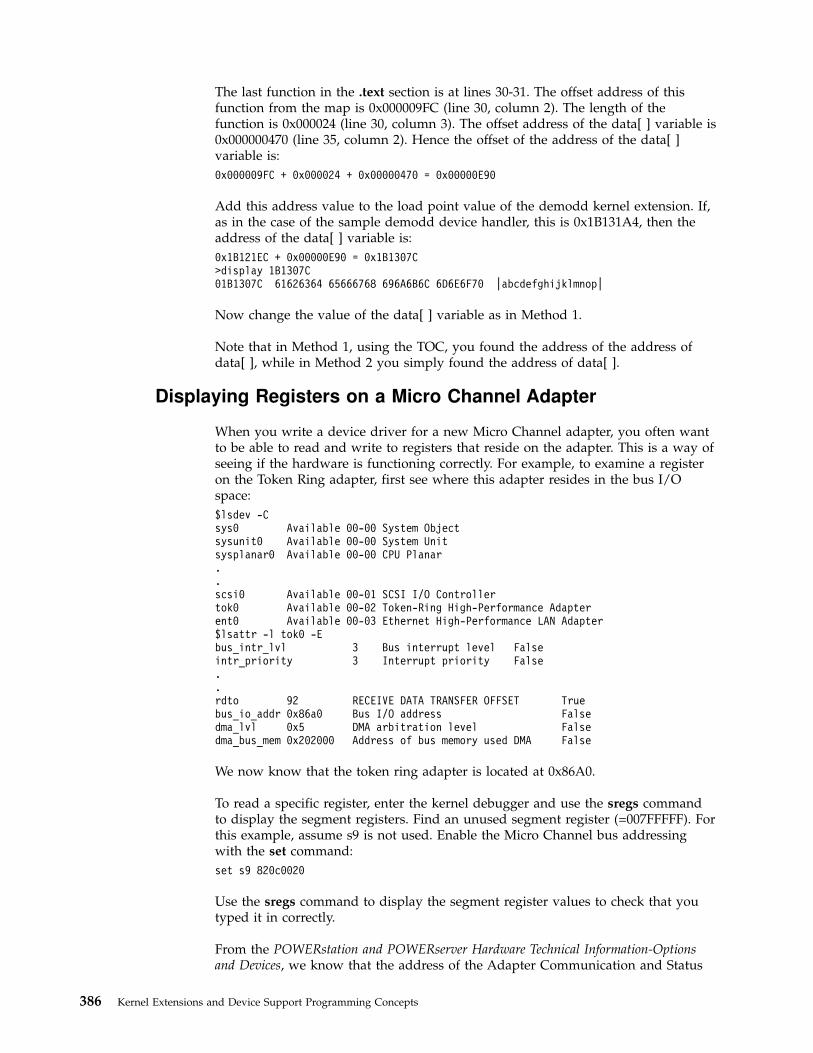
The last function in the .text section is at lines 30-31. The offset address of thisfunction from the map is 0x000009FC (line 30, column 2). The length of thefunction is 0x000024 (line 30, column 3). The offset address of the data[ ] variable is0x000000470 (line 35, column 2). Hence the offset of the address of the data[ ]variable is:
0x000009FC + 0x000024 + 0x00000470 = 0x00000E90
Add this address value to the load point value of the demodd kernel extension. If,as in the case of the sample demodd device handler, this is 0x1B131A4, then theaddress of the data[ ] variable is:
0x1B121EC + 0x00000E90 = 0x1B1307C>display 1B1307C01B1307C 61626364 65666768 696A6B6C 6D6E6F70 |abcdefghijklmnop|
Now change the value of the data[ ] variable as in Method 1.
Note that in Method 1, using the TOC, you found the address of the address ofdata[ ], while in Method 2 you simply found the address of data[ ].
Displaying Registers on a Micro Channel Adapter
When you write a device driver for a new Micro Channel adapter, you often wantto be able to read and write to registers that reside on the adapter. This is a way ofseeing if the hardware is functioning correctly. For example, to examine a registeron the Token Ring adapter, first see where this adapter resides in the bus I/Ospace:
$lsdev -Csys0 Available 00-00 System Objectsysunit0 Available 00-00 System Unitsysplanar0 Available 00-00 CPU Planar..scsi0 Available 00-01 SCSI I/O Controllertok0 Available 00-02 Token-Ring High-Performance Adapterent0 Available 00-03 Ethernet High-Performance LAN Adapter$lsattr -l tok0 -Ebus_intr_lvl 3 Bus interrupt level Falseintr_priority 3 Interrupt priority False..rdto 92 RECEIVE DATA TRANSFER OFFSET Truebus_io_addr 0x86a0 Bus I/O address Falsedma_lvl 0x5 DMA arbitration level Falsedma_bus_mem 0x202000 Address of bus memory used DMA False
We now know that the token ring adapter is located at 0x86A0.
To read a specific register, enter the kernel debugger and use the sregs commandto display the segment registers. Find an unused segment register (=007FFFFF). Forthis example, assume s9 is not used. Enable the Micro Channel bus addressingwith the set command:
set s9 820c0020
Use the sregs command to display the segment register values to check that youtyped it in correctly.
From the POWERstation and POWERserver Hardware Technical Information-Optionsand Devices, we know that the address of the Adapter Communication and Status
386 Kernel Extensions and Device Support Programming Concepts

register is P6a6. The value of P is based on the Bus I/O address (bus_io_addr) ofthe adapter. In the above example, this is 86A0. It could have been anything from86A0 to F6A0 on a 0x1000 byte boundary. Hence P is 8, and the address of theCommunication and Status register is 86A6. The display command now displaysthe two-byte register:
d 900086a6 2
The key is to load a segment register with 820c0020 and then use that segmentregister to reference registers and memory on your adapter. You can use the samemethod to access registers resident on the IOCC. In that case, load the segmentregister with a value of 820c00e0.
Stack Trace
The stack trace gives the stack history which provides the sequence of procedurecalls leading to the current IAR. The Ret Addr is the address of the instructioncalling this procedure. You can use the map file to locate the name of theprocedure. Note that the first stack frame shown is almost always useless, sincedata either has not been saved yet, or is from a previous call. The last functionpreceding the Ret Addr is the function that called the procedure.
You can also use the map command to locate the function name if the functionwas exported. The map <addr> command locates the symbol before the givenaddress. The following is a concise view of the stack:
Low | |Stack grows atAddresses | |this end.
|——————————|Callee's stack -> 0 | Back chain |pointer 4 | Saved CR |
8 | Saved LR |12-16 | Reserved |<—-LINK AREA (callee)
20 | SAVED TOC ||——————————|
Space for P1-P8 | P1 | OUTPUT ARGUMENT AREAis always reserved | ... |<—-(Used by callee to
| Pn | construct argument| Callee's || stack | <—- LOCAL STACK AREA| area ||——————————|| | (Possible word wasted|——————————| for alignment.)
-8*nfprs-4*ngprs —> | Caller's GPR | Rfirst = R13 for fullsave | save area | save
| max 19 words | R31|——————————|
-8*nfprs —> | Caller's FPR | Ffirst = F14 for a| save area | full save| max 18 dblwds | F31|——————————|
Caller's stack -> 0 | Back chain |pointer 4 | Saved CR |
8 | Saved LR |12-16 | Reserved |<—-LINK AREA (caller)
20 | Saved TOC ||——————————|
Space for P1-P8 24 | P1 | INPUT PARAMETER AREAis always reserved | ... | <—-(Callee's input
| Pn | parameters found|——————————| here. Is also
Chapter 17. Debugging Tools 387
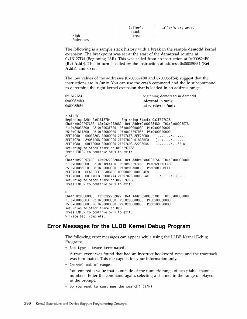
| Caller's | caller's arg area.)| stack |
High | area |Addresses |
The following is a sample stack history with a break in the sample demodd kernelextension. The breakpoint was set at the start of the demoread routine at0x1B127D4 (Beginning IAR). This was called from an instruction at 0x000824B0(Ret Addr). This in turn is called by the instruction at address 0x00085F54 (RetAddr), and so on.
The low values of the addresses (0x000824B0 and 0x00085F54) suggest that theinstructions are in /unix. You can use the crash command and the le subcommandto determine the right kernel extension that is loaded in an address range.
0x1b127d4 beginning demoread in demodd
0x000824b0 .rdevread in /unix
0x00085f54 .cdev_rdwr in /unix
> stackBeginning IAR: 0x01B127D4 Beginning Stack: 0x2FF97C28Chain:0x2FF97C88 CR:0x24222082 Ret Addr:0x000824B0 TOC:0x000C5E78P1:0x2003F800 P2:0x2003F800 P3:0x0000008C P4:0x00000001P5:0x01B11200 P6:0x00000000 P7:0x2FF97D38 P8:0x000000002FF97C60 00000203 00000000 2FF97CF8 2FF7FCD0 |......../.|./...|2FF97C70 29057E6B 00001000 2FF97DC0 018E8BE0 |).xk..../.}.....|2FF97C80 00FF0000 00000000 2FF97CD8 22222044 |......../.|."" D|Returning to Stack frame at 0x2FF97C88Press ENTER to continue or x to exit:>Chain:0x2FF97CD8 CR:0x22222044 Ret Addr:0x00085F54 TOC:0x00000000P1:0x00000000 P2:0x018C41E0 P3:0x2FF97CF8 P4:0x2FF7FCC8P5:0x000850E0 P6:0x00000000 P7:0xDEADBEEF P8:0xDEADBEEF2FF97CC0 DEADBEEF DEADBEEF 00000000 000BE4F8 |................|2FF97CD0 001E70F8 000BE7A4 2FF97D28 000BE5AC |..p...../.}(....|Returning to Stack frame at 0x2FF97CD8Press ENTER to continue or x to exit:...>Chain:0x00000000 CR:0x22222022 Ret Addr:0x0000238C TOC:0x00000000P1:0x00000003 P2:0x30000000 P3:0x00000800 P4:0x00000000P5:0x00000000 P6:0x00000000 P7:0x00000000 P8:0x00000000Returning to Stack frame at 0x0Press ENTER to continue or x to exit:> Trace back complete.
Error Messages for the LLDB Kernel Debug Program
The following error messages can appear while using the LLDB Kernel DebugProgram:
v Bad type — trace terminated.
A trace event was found that had an incorrect hookword type, and the tracebackwas terminated. This message is for your information only.
v Channel out of range.
You entered a value that is outside of the numeric range of acceptable channelnumbers. Enter the command again, selecting a channel in the range displayedin the prompt.
v Do you want to continue the search? (Y/N)
388 Kernel Extensions and Device Support Programming Concepts

Ten consecutive pages were not in storage. To continue the search, enter Y (yes).To exit the search enter N (no).
v The address you specified is not in real storage.
The command was rejected because the data at the address you specified hasbeen paged out of RAM to disk. Enter the command again with a data addressthat is currently in RAM.
v The page at Address is not in real storage.
The search passed over a page that was not in storage. Action is not required.This message is for your information only.
v The value cannot be found.
You specified a value that cannot be found or was not in real storage. Action isnot required. This message is for your information only.
v This breakpoint is undefined or not currently addressable.
The breakpoint was not cleared because it is undefined or its segment is notcurrently addressable. Try to load the segment ID into a segment register withthe set command.
v Timestamp paged out.
A trace data structure is not currently paged into physical memory. Enter thecommand again later when the data structure is available.
v Trace data paged out.
A trace data structure is not currently paged into physical memory. Enter thecommand again later when the data structure is available.
v Trace entry paged out.
A trace data structure is not currently paged into physical memory. Enter thecommand again later when the data structure is available.
v Trace header paged out.
A trace data structure is not currently paged into physical memory. Enter thecommand again later when the data structure is available.
v Trace Queue header paged out.
A trace data structure is not currently paged into physical memory. Enter thecommand again later when the data structure is available.
v You cannot set more than 32 breakpoints.
The breakpoint is not set because you tried to set more than the maximumnumber of breakpoints allowed on the system. Clear at least one breakpointbefore setting another breakpoint.
v You cannot Step or Go into paged-out storage.
The command cannot run because you specified an address for the commandthat is in paged-out storage. Specify an address that is not in paged-out storage.
v You did not enter all required parameters.
The command was unsuccessful because you did not specify all the requiredparameters. Enter the command again with the necessary parameters.
v You entered a parameter that is not valid.
The command was unsuccessful because you specified a parameter that thedebug program did not recognize. Check the spelling and syntax of theparameter you specified. Then, enter the command again with a valid parameter.
Chapter 17. Debugging Tools 389

KDB Kernel Debugger and Command
This chapter provides information about the KDB Kernel Debugger and kdbCommand. The kdb Command is primarily used for analysis of system dumps.The KDB Kernel Debugger is primarily used as a debugging tool for device driverdevelopment. The following topics are included in this chapter:
v KDB Kernel Debugger and kdb Command
v Subcommands for the KDB Kernel Debugger and kdb Command
v Using the KDB Kernel Debug Program
KDB Kernel Debugger and kdb Command
This document describes the KDB Kernel Debugger and kdb command. It isimportant to understand that the KDB Kernel Debugger and the kdb command aretwo separate entities. The KDB Kernel Debugger is a debugger for use indebugging the kernel, device drivers, and other kernel extensions. The kdbcommand is primarily a tool for viewing data contained in system image dumps.However, the kdb command may be run on an active system to view system data.
The reason that the KDB Kernel Debugger and kdb command are both coveredtogether is that they share a large number of subcommands. This provides for easeof use when switching from between the kernel debugger and command. Mostsubcommands for viewing kernel data structures are included in both. However,the KDB Kernel Debugger includes additional subcommands for execution control(breakpoints, step commands, etc...) and processor control (start/stop CPUs, reboot,etc...). The kdb command also has subcommands which are unique; these involvemanipulation of system image dumps.
The following sections outline how to invoke the KDB Kernel Debugger and kdbcommand. They also describe features which are unique to each.
v “The kdb Command”
v “KDB Kernel Debugger” on page 391
v “Loading and Starting the KDB Kernel Debugger” on page 391
v “Using a Terminal with the KDB Kernel Debugger” on page 392
v “Entering the KDB Kernel Debugger” on page 392
v “Debugging Multiprocessor Systems” on page 393
v “Kernel Debug Program Concepts” on page 393
The complete list of subcommands available for the KDB Kernel Debugger andkdb command are included in “Subcommands for the KDB Kernel Debugger andkdb Command” on page 394.
The kdb CommandThe kdb command is an interactive tool that allows examination of an operatingsystem image. An operating system image is held in a system dump file; either asa file or on the dump device. The kdb command may also be used on an activesystem for viewing the contents of system structures. This is a useful tool fordevice driver development and debugging. The syntax for invoking the kdbcommand is:
kdb [SystemImageFile [KernelFile]]
390 Kernel Extensions and Device Support Programming Concepts

The SystemImageFile parameter specifies the file that contains the system image.The default SystemImageFile is /dev/mem. The KernelFile parameter contains thekernel symbol definitions. The default for the KernelFile is /usr/lib/boot/unix.
Root permissions are required for execution of the kdb command on the activesystem. This is required because the special file /dev/mem is used. To run the kdbcommand on the active system, enter:
kdb
To invoke the kdb command on a system image file, enter:
kdb SystemImageFile
where SystemImageFile is either a file name or the name of the dump device. Wheninvoked to view data from a SystemImageFile the kdb command sets the defaultthread to the thread running at the time the SystemImageFile was created.
Notes:
1. When using the kdb command a kernel file must be available.
2. Stack tracing of the current process on a running system does not work
KDB Kernel DebuggerThe KDB Kernel Debugger is used for debugging the kernel, device drivers, andother kernel extensions. The KDB Kernel Debugger provides the followingfunctions:
v Setting breakpoints within the kernel or kernel extensions
v Execution control through various forms of step commands
v Formatted display of selected kernel data structures
v Display and modification of kernel data
v Display and modification of kernel instructions
v Modification of the state of the machine through alteration of system registers
Loading and Starting the KDB Kernel DebuggerThe KDB Kernel Debugger must be loaded at boot time. This requires that a bootimage be created with the debugger enabled. To enable the KDB Kernel Debuggerthe bosdebug and bosboot commands must be used. The first step in preparing aboot image to include the KDB Kernel Debugger is to set an indicator that theKDB Kernel is to be used in building the boot image, this indicator is checked bythe bosboot command which actually builds the boot images. To set the indicatorthat a KDB Kernel is to be used in building building boot images is accomplishedby executing the following command:
bosdebug -K
This indicator may be turned off by executing the following command:
bosdebug -o
Note, execution of the above command clears all flags set by previous invocationsof bosdebug. Therefore, it may be necessary to execute additional bosdebugcommands if there are debug options which need to be enabled.
To complete the task of building a boot image with the KDB Kernel, the bosbootcommand must be executed. The following commands may be used to build aboot image using a KDB Kernel:
Chapter 17. Debugging Tools 391

1. bosboot -a -d /dev/ipldevice
2. bosboot -a -d /dev/ipldevice -D
3. bosboot -a -d /dev/ipldevice -I
The above commands build boot images using the KDB Kernel (if previouslyselected by bosdebug) having the following characteristics: 1) KDB Kerneldebugger is disabled, 2) KDB Kernel Debugger is enabled but is not invokedduring system initialization, 3) KDB Kernel Debugger is enabled and is invokedduring system initialization. Note, execution of the bosboot builds the boot imageonly; the boot image is not used until the machine is restarted.
Notes:
1. External interrupts are disabled while the KDB Kernel Debugger is active
2. If invoked during system initialization the g subcommand must be issuedto continue the initialization process.
Using a Terminal with the KDB Kernel DebuggerThe KDB Kernel Debugger opens an asynchronous ASCII terminal when it is firststarted, and subsequently upon being started due to a system halt. Native serialports are checked sequentially starting with port 0 (zero). Each port is configuredat 9600 bps, 8 bits, and no parity. If carrier detect is asserted within 1/10 seconds,then the port is used. Otherwise, the next available native port is checked. Thisprocess continues until a port is opened or until every native port available on themachine has been checked. If no native serial port is opened successfully, then theresult is unpredictable.
The KDB Kernel Debugger only supports display to an ASCII terminal connectedto a native serial port. Displays connected to graphics adapters are not supported.The KDB Kernel Debugger has its own device driver for handling the displayterminal. It is possible to connect a serial line between two machines and definethe serial line port as the port for the console. In that case, the cu command maybe used to connect to the target machine and run the KDB Kernel Debugger.
Note: If a serial device, other than a terminal connected to a native serialport, is selected by the kernel debugger, the system may appear to hang up.
Entering the KDB Kernel DebuggerIt is possible to enter the KDB Kernel Debugger using one of the followingprocedures:
v From a native keyboard, press Ctrl-Alt-Numpad4.
v From a tty keyboard, enter Ctrl-4 (IBM 3151 terminals) or Ctrl-\ (BQ 303, BQ310C, and WYSE 50).
v The system can enter the debugger if a breakpoint is set. To do this, use one ofthe Breakpoints/Steps Subcommands.
v The system can also enter the debugger by calling the brkpoint subroutine fromC code. The syntax for calling this subroutine is:
brkpoint();
v The system can also enter the debugger if a system halt is caused by a fatalsystem error. In such a case, the system creates a log entry in the system log andif the KDB Kernel Debugger is available, it is called. A system dump may begenerated on exit from the debugger.
392 Kernel Extensions and Device Support Programming Concepts

If the kernel debug program is not available (nothing happens when you type inthe above key sequence), you must load it. To do this, see “Loading and Startingthe KDB Kernel Debugger” on page 391.
Note: You can use the kdb command to determine whether the KDB KernelDebugger is available. Use the dw subcommand:
# kdb(0)> dw kdb_avail(0)> dw kdb_wanted
If either of the above dw subcommands returns a 0, the KDB KernelDebugger is not available.
Once the KDB Kernel Debugger has been invoked the subcommands detailed inSubcommands for the KDB Kernel Debugger and kdb Command are available.
Debugging Multiprocessor SystemsOn multiprocessor systems, entering the KDB Kernel Debugger stops all processors(except the current processor running the debug program itself). The prompt onmultiprocessor systems indicates the current processor. For example:
v KDB(0)> - indicates processor 0 is the current processor
v KDB(5)> - indicates processor 5 is the current processor
In addition to the change in the prompt for multiprocessor systems, there are alsosubcommands which are unique to these systems. Refer to SMP Subcommands fordetails.
Kernel Debug Program ConceptsWhen the KDB Kernel Debugger is invoked, it is the only running program. Allprocesses are stopped and interrupts are disabled. The KDB Kernel Debugger runswith its own Machine State Save Area (mst) and a special stack. In addition theKDB Kernel Debugger does not run AIX routines. Though this requires that kernelcode be duplicated within KDB, it is possible to break anywhere within the kernelcode. When exiting the KDB Kernel Debugger, all processes continue to run unlessthe debugger was entered via a system halt.
CommandsThe KDB Kernel debugger must be loaded and started before it can acceptcommands. Once in the debugger, use the commands to investigate and makealterations. See Subcommands for the KDB Kernel Debugger and KDB Commandfor lists and descriptions of the subcommands.
BreakpointsThe KDB Kernel Debugger creates a table of breakpoints that it maintains. When abreakpoint is set, the debugger temporarily replaces the corresponding instructionwith the trap instruction. The instruction overlaid by the breakpoint operates whenyou issue any subcommand that would cause that instruction to be executed.
For more information on setting/clearing breakpoints and execution control see“Setting Breakpoints” on page 530.
Chapter 17. Debugging Tools 393

Subcommands for the KDB Kernel Debugger and kdb Command
Introduction to Subcommands
Numeric ValuesNumeric arguements for the subcommands presented in this section are requiredto be hexadecimal, except for arguments that specify slot numbers and argumentsto the dcal subcommand. Slot numbers and arguements for the dcal subcommandmust be decimal values.
RegistersRegister values may be referenced by the KDB Kernel Debugger and kdbcommand. Register values may be used in subcommands by preceding the registername with an ″@″ character. This character is also used to deference addresses asexplained later. The list of registers that may be referenced include:
asr Address space register
cr Condition register
ctr Count register
dar Data address register
dec Decrementer
dsisr Data storage interrupt status register
fp0-fp31 Floating point registers 0 through 31.
fpscr Floating point status and control register
iar Instruction address register
lr Link register
mq Multiply quotient
msr Machine State register
r0-r31 General Purpose Registers 0 through 31
rtcl Real Time clock (nanoseconds)
rtcu Real Time clock (seconds)
s0-s15 Segment registers.
sdr0 Storage description register 0
sdr1 Storage description register 1
srr0 Machine status save/restore 0
srr1 Machine status save/restore 1
tbl Time base register, lower
tbu Time base register, upper
tid Transaction register (fixed point)
xer Exception register (fixed point)
Other special purposes registers that may be referenced, if supported on thehardware, include: sprg0, sprg1, sprg2, sprg3, pir, fpecr, ear, pvr, hid0, hid1, iabr,dmiss, imiss, dcmp, icmp, hash1, hash2, rpa, buscsr, l2cr, l2sr, mmcr0, mmcr1,pmc1-pmc8, sia, and sda.
ExpressionsThe KDB Kernel Debugger and kdb command do not provide full expressionprocessing. Expressions can only contain symbols, hex constants, references toregister or memory locations, and operators. Furthermore, symbols are onlyallowed as the first operand of an expression. Supported operators include:
+ Addition
- Subtraction
* Multiplication
394 Kernel Extensions and Device Support Programming Concepts

/ Division
@ Dereferencing
The dereference operator indicates that the value at the location indicated by thenext operand is to be used in the calculation of the expression. For example, @f000would indicate that the value at address 0x0000f000 should be used in evaluationof the expression. The dereference operator is also used to access the contents ofregister. For example, @r1 references the contents of general purpose register 1.Recursive dereferencing is allowed. As an example, @@r1 references the value atthe address pointed to by the value at the address contained in general purposeregister 1.
Expressions are processed from left to right only. There is no operator precedence.
Examples
Valid Expressions Results
dw @r1 displays data at the location pointed to by r1
dw @@r1 displays data at the location pointed to by value atlocation pointed to by r1
dw open displays data at the address beginning of the open routine
dw open+12 displays data twelve bytes past the beginning of the openroutine
Invalid Expressions Problem
dw @r1+open symbols can only be the first operand
dw r1 must include @ to reference the contents of r1, if a symbolr1 existed this would be valid
dw @r1+(4*3) parentheses are not supported
Subcommand ArgumentsThe following table describes the most common argument types referenced in thesubcommand syntax diagrams that follow.
Argument Description
* A wildcard used to select all entries.
count A hex constant specifying the number of times to perform aspecific operation.
cpu A decimal value specifying a cpu number in a SMP machine
dev eaddr An effective address for device memory.
dev paddr A physical address for device memory.
eaddr Effective address. This may be a hex contstant or an expression.
phys. addr A physical address
pid A hex constant or expression specifying a process ID.
selection Indicates that a menu is displayed from which a selection mustbe made.
slot A decimal constant specifying a slot number within a table.
symb A symbolic reference to a value. Symbols from the kernel and/orkernel extensions may be used.
Chapter 17. Debugging Tools 395

Argument Description
tid A hex constant or expression specifying a thread ID.
KDB Kernel Debug Program Subcommands grouped inAlphabetical Order
The following table shows the KDB Kernel Debug Program subcommands inalphabetical order:
Subcommand Alias Alias Function Argument Task Category
ames - - VMM addressmap entries
[symb/eaddr] VMM
apt - - VMM APT entries [selection] VMM
asc ascsi - Display ascsi [slot/symb/eaddr] SCSI
B - - step on branch [count] Breakpoints/Steps
b brk - set/list breakpoint(s)
[-p/-v] [symb/addr] Breakpoints/Steps
bt - - set/list tracepoint(s)
[-p/-v] [symb/addr[script ] [cond]]
Trace
btac - - branch target [-p/-v] [symb/eaddr] btac/BRAT
buf buffer - Display buffer [slot/symb/eaddr] File System
c cl - clear break point [slot|[-p/-v]symb/addr]
Breakpoints/Steps
ca - - clear all breakpoints
- Breakpoints/Steps
cat - - clear all tracepoints
- Trace
cbtac - - clear branch target - btac/BRAT
cdt - - Display cdt [?] Basic
cku cku_priv - Display ckuprivate
symb/eaddr File System
clk cpl - Display complexlock
[symb/eaddr] System Table
cpu - - Switch to cpu [cpu number | any] SMP
ct - - clear trace point slot|[-p/-v] symb/addr Trace
ctx - context switch to KDBcontext
[cpu number] Basic
cw stop-cl - clear watch - Watch
d dump - display byte data symb/eaddr [count] Dumps/Display/Decode
dbat - - display dbats [index] bat/Block AddressTranslation
dc dis - display code symb/eaddr [count] Dumps/Display/Decode
dcal - - calc/conv adecimal expr
decimal expression Calculator Converter
dd - - display doubleword data
symb/eaddr [count] Dumps/Display/Decode
396 Kernel Extensions and Device Support Programming Concepts
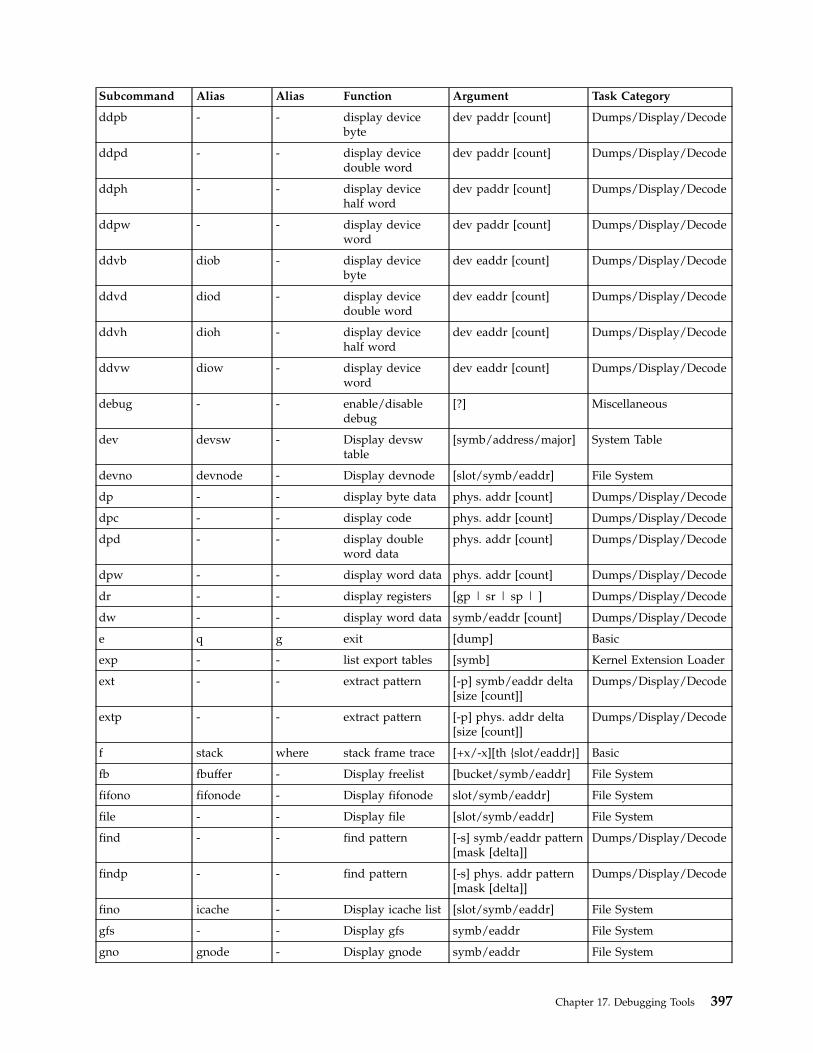
Subcommand Alias Alias Function Argument Task Category
ddpb - - display devicebyte
dev paddr [count] Dumps/Display/Decode
ddpd - - display devicedouble word
dev paddr [count] Dumps/Display/Decode
ddph - - display devicehalf word
dev paddr [count] Dumps/Display/Decode
ddpw - - display deviceword
dev paddr [count] Dumps/Display/Decode
ddvb diob - display devicebyte
dev eaddr [count] Dumps/Display/Decode
ddvd diod - display devicedouble word
dev eaddr [count] Dumps/Display/Decode
ddvh dioh - display devicehalf word
dev eaddr [count] Dumps/Display/Decode
ddvw diow - display deviceword
dev eaddr [count] Dumps/Display/Decode
debug - - enable/disabledebug
[?] Miscellaneous
dev devsw - Display devswtable
[symb/address/major] System Table
devno devnode - Display devnode [slot/symb/eaddr] File System
dp - - display byte data phys. addr [count] Dumps/Display/Decode
dpc - - display code phys. addr [count] Dumps/Display/Decode
dpd - - display doubleword data
phys. addr [count] Dumps/Display/Decode
dpw - - display word data phys. addr [count] Dumps/Display/Decode
dr - - display registers [gp | sr | sp | ] Dumps/Display/Decode
dw - - display word data symb/eaddr [count] Dumps/Display/Decode
e q g exit [dump] Basic
exp - - list export tables [symb] Kernel Extension Loader
ext - - extract pattern [-p] symb/eaddr delta[size [count]]
Dumps/Display/Decode
extp - - extract pattern [-p] phys. addr delta[size [count]]
Dumps/Display/Decode
f stack where stack frame trace [+x/-x][th {slot/eaddr}] Basic
fb fbuffer - Display freelist [bucket/symb/eaddr] File System
fifono fifonode - Display fifonode slot/symb/eaddr] File System
file - - Display file [slot/symb/eaddr] File System
find - - find pattern [-s] symb/eaddr pattern[mask [delta]]
Dumps/Display/Decode
findp - - find pattern [-s] phys. addr pattern[mask [delta]]
Dumps/Display/Decode
fino icache - Display icache list [slot/symb/eaddr] File System
gfs - - Display gfs symb/eaddr File System
gno gnode - Display gnode symb/eaddr File System
Chapter 17. Debugging Tools 397
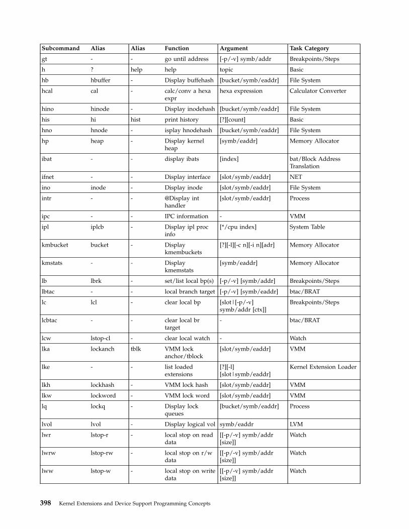
Subcommand Alias Alias Function Argument Task Category
gt - - go until address [-p/-v] symb/addr Breakpoints/Steps
h ? help help topic Basic
hb hbuffer - Display buffehash [bucket/symb/eaddr] File System
hcal cal - calc/conv a hexaexpr
hexa expression Calculator Converter
hino hinode - Display inodehash [bucket/symb/eaddr] File System
his hi hist print history [?][count] Basic
hno hnode - isplay hnodehash [bucket/symb/eaddr] File System
hp heap - Display kernelheap
[symb/eaddr] Memory Allocator
ibat - - display ibats [index] bat/Block AddressTranslation
ifnet - - Display interface [slot/symb/eaddr] NET
ino inode - Display inode [slot/symb/eaddr] File System
intr - - @Display inthandler
[slot/symb/eaddr] Process
ipc - - IPC information - VMM
ipl iplcb - Display ipl procinfo
[*/cpu index] System Table
kmbucket bucket - Displaykmembuckets
[?][-l][-c n][-i n][adr] Memory Allocator
kmstats - - Displaykmemstats
[symb/eaddr] Memory Allocator
lb lbrk - set/list local bp(s) [-p/-v] [symb/addr] Breakpoints/Steps
lbtac - - local branch target [-p/-v] [symb/eaddr] btac/BRAT
lc lcl - clear local bp [slot|[-p/-v]symb/addr [ctx]]
Breakpoints/Steps
lcbtac - - clear local brtarget
- btac/BRAT
lcw lstop-cl - clear local watch - Watch
lka lockanch tblk VMM lockanchor/tblock
[slot/symb/eaddr] VMM
lke - - list loadedextensions
[?][-l][slot|symb/eaddr]
Kernel Extension Loader
lkh lockhash - VMM lock hash [slot/symb/eaddr] VMM
lkw lockword - VMM lock word [slot/symb/eaddr] VMM
lq lockq - Display lockqueues
[bucket/symb/eaddr] Process
lvol lvol - Display logical vol symb/eaddr LVM
lwr lstop-r - local stop on readdata
[[-p/-v] symb/addr[size]]
Watch
lwrw lstop-rw - local stop on r/wdata
[[-p/-v] symb/addr[size]]
Watch
lww lstop-w - local stop on writedata
[[-p/-v] symb/addr[size]]
Watch
398 Kernel Extensions and Device Support Programming Concepts

Subcommand Alias Alias Function Argument Task Category
m - - modify sequentialbytes
symb/eaddr Modify Memory
mbuf - - Display mbuf [tcp/udp][symb/eaddr]
NET
md - - modify sequentialdouble word
symb/eaddr Modify Memory
mdbat - - modify dbats [index] bat/Block AddressTranslation
mdpb - - modify devicebyte
dev paddr Modify Memory
mdpd - - modify devicedouble word
dev paddr Modify Memory
mdph - - modify device half dev paddr Modify Memory
mdpw - - modify deviceword
dev paddr Modify Memory
mdvb miob - modify devicebyte
dev eaddr Modify Memory
mdvd miod - modify devicedouble word
dev eaddr Modify Memory
mdvh mioh - modify device half dev eaddr Modify Memory
mdvw miow - modify deviceword
dev eaddr Modify Memory
mibat - - modify ibats [index] bat/Block AddressTranslation
mp - - modify sequentialbytes
phys. addr Modify Memory
mpd - - modify sequentialdouble word
phys. addr Modify Memory
mpw - - modify sequentialword
phys. addr Modify Memory
mr - - modify registers [gp | sr | sp | ] Modify Memory
mst - - Display mst area [slot] [[-a] symb/eaddr] Process
mw - - modify sequentialword
symb/eaddr Modify Memory
n nexti - next instruction [count] Breakpoints/Steps
nm - - translate symbolto eaddr
symb Namelist/Symbol
ns - - no symbol mode(toggle)
- Namelist/Symbol
p proc - Display proc table [*/slot/symb/eaddr] Process
pbuf pbuf - Display physicalbuf
[*] symb/eaddr LVM
pdt - - VMM pagingdevice table
[*][slot] VMM
pfhdata - - VMM controlvariables
- VMM
pft - - VMM PFT entries [selection] VMM
Chapter 17. Debugging Tools 399
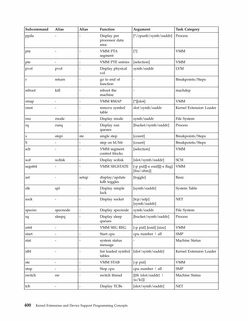
Subcommand Alias Alias Function Argument Task Category
ppda - - Display perprocessor dataarea
[*/cpunb/symb/eaddr] Process
pta - - VMM PTAsegment
[?] VMM
pte - - VMM PTE entries [selection] VMM
pvol pvol - Display physicalvol
symb/eaddr LVM
r return - go to end offunction
- Breakpoints/Steps
reboot kill - reboot themachine
- machdep
rmap - - VMM RMAP [*][slot] VMM
rmst - - remove symboltable
slot|symb/eaddr Kernel Extension Loader
rno rnode - Display rnode symb/eaddr File System
rq runq - Display runqueues
[bucket/symb/eaddr] Process
s stepi ste single step [count] Breakpoints/Steps
S - - step on bl/blr [count] Breakpoints/Steps
scb - - VMM segmentcontrol blocks
[selection] VMM
scd scdisk - Display scdisk [slot/symb/eaddr] SCSI
segst64 - - VMM SEGSTATE [-p pid][-e esid][[-s flag][fno|shm]]
VMM
set - setup display/updatekdb toggles
[toggle] Basic
slk spl - Display simplelock
[symb/eaddr] System Table
sock - - Display socket [tcp/udp][symb/eaddr]
NET
specno specnode - Display specnode symb/eaddr File System
sq sleepq - Display sleepqueues
[bucket/symb/eaddr] Process
sr64 - - VMM SEG REG [-p pid] [esid] [size] VMM
start - - Start cpu cpu number | all SMP
stat - - system statusmessage
- Machine Status
stbl - - list loaded symboltables
[slot|symb/eaddr] Kernel Extension Loader
ste - - VMM STAB [-p pid] VMM
stop - - Stop cpu cpu number | all SMP
switch sw - switch thread [[th {slot/eaddr} |{u/k}]]
Machine Status
tcb - - Display TCBs [slot/symb/eaddr] NET
400 Kernel Extensions and Device Support Programming Concepts

Subcommand Alias Alias Function Argument Task Category
tcpcb - - Display TCP CB [tcp/udp][symb/eaddr]
NET
test [ - bt condition [symb/eaddr ==symb/eaddr]
Conditional
test [ - bt condition [symb/eaddr !=symb/eaddr]
Conditional
test [ - bt condition [symb/eaddr >=symb/eaddr]
Conditional
test [ - bt condition [symb/eaddr <=symb/eaddr]
Conditional
test [ - bt condition [symb/eaddr >symb/eaddr]
Conditional
test [ - bt condition [symb/eaddr <symb/eaddr]
Conditional
test [ - bt condition [symb/eaddr |
symb/eaddr]Conditional
test [ - bt condition [symb/eaddr &symb/eaddr]
Conditional
test [ - bt condition [symb/eaddr |symb/eaddr]
Conditional
time - - display elapsedtime
- Miscellaneous
th thread - Display threadtable
[*/slot/symb/eaddr/-w?]
Process
tpid th_pid - Display thread pid [pid] Process
tr - - translate to realaddress
symb/eaddr Address Translation
trace - - Display tracebuffer
[?] System Table
trb timer - Display systemtimer requestblocks
- System Table
ts - - translate eaddr tosymbol
eaddr Namelist/Symbol
ttid th_tid - Display thread tid [tid] Process
tv - - display MMUtranslation
symb/eaddr Address Translation
u user - Display u_area [-?][slot/symb/eaddr] Process
udb - - Display UDBs [slot/symb/eaddr] NET
var - - Display var - System Table
vfs mount - Display vfs [slot/slot/symb/eaddr] File System
vmdmap - - VMM disk map [slot/symb/eaddr] VMM
vmlocks vmlock vl VMM spin locks - VMM
vmaddr - - VMM Addresses - VMM
vmker - - VMM kernelsegment data
- VMM
vmlog - - VMM error log - VMM
Chapter 17. Debugging Tools 401

Subcommand Alias Alias Function Argument Task Category
vmstat - - VMM statistics - VMM
vmwait - - VMM wait status [symb/eaddr] VMM
vno vnode - Display vnode symb/eaddr File System
volgrp volgrp - Display volumegroup
symb/eaddr LVM
vrld - - VMM reload xlatetable
- VMM
vsc vscsi - Display vscsi [slot/symb/eaddr] SCSI
wr stop-r - stop on read data [[-p/-v] symb/addr[size]]
Watch
wrw stop-rw - stop on r/w data [[-p/-v] symb/addr[size]]
Watch
ww stop-w - stop on write data [[-p/-v] symb/addr[size]]
Watch
xm xmalloc - Display heapdebug
[-?] Memory Allocator
zproc - - VMM zeroingkproc
- VMM
KDB Kernel Debug Subcommands grouped by Task Category
Basic Subcommands
Subcommand Alias Alias Function Argument
h ? help help topic
his hi hist print history [?][count]
e q g exit [dump]
set - setup display/update kdbtoggles
[toggle]
f stack where stack frame trace [+x/-x][th{slot/eaddr}]
ctx - context switch to KDBcontext
[cpu number]
cdt (“cdtSubcommand” onpage 419)
- - Display cdt [?]
Trace Subcommands
Subcommand Alias Alias Function Argument
bt - - set/list trace point(s) [-p/-v] [symb/addr[script] [cond]]
ct - - clear trace point slot|[-p/-v]symb/addr
cat - - clear all trace points -
402 Kernel Extensions and Device Support Programming Concepts

Breakpoints/Steps Subcommands
Subcommand Alias Alias Function Argument
b brk - set/list break point(s) [-p/-v] [symb/addr]
lb lbrk - set/list local bp(s) [-p/-v] [symb/addr]
c cl - clear break point [slot|[-p/-v]symb/addr]
lc lcl - clear local bp [slot|[-p/-v]symb/addr [ctx]]
ca - - clear all break points -
r return - go to end of function -
gt - - go until address [-p/-v] symb/addr
n nexti - next instruction [count]
s stepi ste single step [count]
S - - step on bl/blr [count]
B - - step on branch [count]
Dumps/Display/Decode Subcommands
Subcommand Alias Alias Function Argument
d dump - display byte data symb/eaddr [count]
dw - - display word data symb/eaddr [count]
dd - - display double worddata
symb/eaddr [count]
dp - - display byte data phys. addr [count]
dpw - - display word data phys. addr [count]
dpd - - display double worddata
phys. addr [count]
dc dis - display code symb/eaddr [count]
dpc - - display code phys. addr [count]
dr - - display registers [gp | sr | sp | >regnam>]
ddvb diob - display device byte dev eaddr [count]
ddvh dioh - display device halfword
dev eaddr [count]
ddvw diow - display device word dev eaddr [count]
ddvd diod - display device doubleword
dev eaddr [count]
ddpb - - display device byte dev paddr [count]
ddph - - display device halfword
dev paddr [count]
ddpw - - display device word dev paddr [count]
ddpd - - display device doubleword
dev paddr [count]
find - - find pattern [-s] symb/eaddrpattern [mask [delta]]
Chapter 17. Debugging Tools 403

Subcommand Alias Alias Function Argument
findp - - find pattern [-s] phys. addrpattern [mask [delta]]
ext - - extract pattern [-p] symb/eaddrdelta [size [count]]
extp - - extract pattern [-p] phys. addr delta[size [count]]
Modify Memory Subcommands
Subcommand Alias Alias Function Argument
m - - modify sequentialbytes
symb/eaddr
mw - - modify sequentialword
symb/eaddr
md - - modify sequentialdouble word
symb/eaddr
mp - - modify sequentialbytes
phys. addr
mpw - - modify sequentialword
phys. addr
mpd - - modify sequentialdouble word
phys. addr
mr - - modify registers [gp | sr | sp | >regnam>]
mdvb miob - modify device byte dev eaddr
mdvh mioh - modify device half dev eaddr
mdvw miow - modify device word dev eaddr
mdvd miod - modify device doubleword
dev eaddr
mdpb - - modify device byte dev paddr
mdph - - modify device half dev paddr
mdpw - - modify device word dev paddr
mdpd - - modify device doubleword
dev paddr
Namelist/Symbol Subcommands
Subcommand Alias Alias Function Argument
nm - - translate symbol toeaddr
symb
ns - - no symbol mode(toggle)
-
ts - - translate eaddr tosymbol
eaddr
404 Kernel Extensions and Device Support Programming Concepts

Watch Break Point Subcommands
Subcommand Alias Alias Function Argument
wr stop-r - stop on read data [[-p/-v] symb/addr[size]]
ww stop-w - stop on write data [[-p/-v] symb/addr[size]]
wrw stop-rw - stop on r/w data [[-p/-v] symb/addr[size]]
cw stop-cl - clear watch -
lwr lstop-r - local stop on readdata
[[-p/-v] symb/addr[size]]
lww lstop-w - local stop on writedata
[[-p/-v] symb/addr[size]]
lwrw lstop-rw - local stop on r/wdata
[[-p/-v] symb/addr[size]]
lcw lstop-cl - clear local watch -
Miscellaneous Subcommands
Subcommand Alias Alias Function Argument
time - - display elapsed time -
debug - - enable/disable debug [?]
Conditional Subcommands
Subcommand Alias Alias Function Argument
test [ - bt condition [symb/eaddr ==symb/eaddr]
test [ - bt condition [symb/eaddr !=symb/eaddr]
test [ - bt condition [symb/eaddr >=symb/eaddr]
test [ - bt condition [symb/eaddr <=symb/eaddr]
test [ - bt condition [symb/eaddr >symb/eaddr]
test [ - bt condition [symb/eaddr <symb/eaddr]
test [ - bt condition [symb/eaddr |
symb/eaddr]
test [ - bt condition [symb/eaddr &symb/eaddr]
test [ - bt condition [symb/eaddr |symb/eaddr]
Chapter 17. Debugging Tools 405

Calculator Converter Subcommands
Subcommand Alias Alias Function Argument
hcal cal - calc/conv a hexa expr hexa expression
dcal (“hcal and dcalSubcommands” onpage 439)
- - calc/conv a decimalexpr
decimal expression
Machine Status Subcommands
Subcommand Alias Alias Function Argument
stat - - system statusmessage
-
switch sw - switch thread [[th {slot/eaddr} |{u/k}]]
Kernel Extension Loader Subcommands
Subcommand Alias Alias Function Argument
lke - - list loaded extensions [?][-l][slot|symb/eaddr]
stbl - - list loaded symboltables
[slot|symb/eaddr]
rmst - - remove symbol table slot|symb/eaddr
exp - - list export tables [symb]
Address Translation Subcommands
Subcommand Alias Alias Function Argument
tr - - translate to realaddress
symb/eaddr
tv - - display MMUtranslation
symb/eaddr
Process Subcommands
Subcommand Alias Alias Function Argument
ppda - - Display per processordata area
[*/cpunb/symb/eaddr]
intr - - @Display int handler [slot/symb/eaddr]
mst - - Display mst area [slot] [[-a]symb/eaddr]
p proc - Display proc table [*/slot/symb/eaddr]
th thread - Display thread table [*/slot/symb/eaddr/-w?]
ttid th_tid - Display thread tid [tid]
tpid th_pid - Display thread pid [pid]
rq runq - Display run queues [bucket/symb/eaddr]
sq sleepq - Display sleep queues [bucket/symb/eaddr]
406 Kernel Extensions and Device Support Programming Concepts
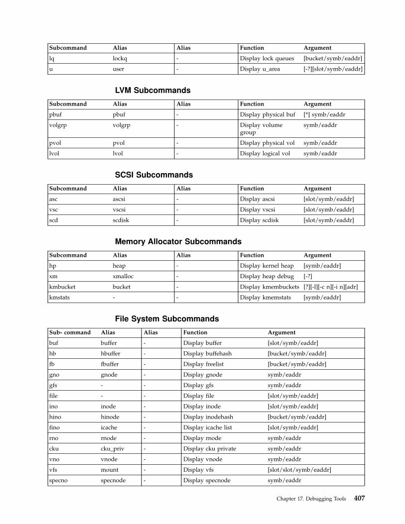
Subcommand Alias Alias Function Argument
lq lockq - Display lock queues [bucket/symb/eaddr]
u user - Display u_area [-?][slot/symb/eaddr]
LVM Subcommands
Subcommand Alias Alias Function Argument
pbuf pbuf - Display physical buf [*] symb/eaddr
volgrp volgrp - Display volumegroup
symb/eaddr
pvol pvol - Display physical vol symb/eaddr
lvol lvol - Display logical vol symb/eaddr
SCSI Subcommands
Subcommand Alias Alias Function Argument
asc ascsi - Display ascsi [slot/symb/eaddr]
vsc vscsi - Display vscsi [slot/symb/eaddr]
scd scdisk - Display scdisk [slot/symb/eaddr]
Memory Allocator Subcommands
Subcommand Alias Alias Function Argument
hp heap - Display kernel heap [symb/eaddr]
xm xmalloc - Display heap debug [-?]
kmbucket bucket - Display kmembuckets [?][-l][-c n][-i n][adr]
kmstats - - Display kmemstats [symb/eaddr]
File System Subcommands
Sub- command Alias Alias Function Argument
buf buffer - Display buffer [slot/symb/eaddr]
hb hbuffer - Display buffehash [bucket/symb/eaddr]
fb fbuffer - Display freelist [bucket/symb/eaddr]
gno gnode - Display gnode symb/eaddr
gfs - - Display gfs symb/eaddr
file - - Display file [slot/symb/eaddr]
ino inode - Display inode [slot/symb/eaddr]
hino hinode - Display inodehash [bucket/symb/eaddr]
fino icache - Display icache list [slot/symb/eaddr]
rno rnode - Display rnode symb/eaddr
cku cku_priv - Display cku private symb/eaddr
vno vnode - Display vnode symb/eaddr
vfs mount - Display vfs [slot/slot/symb/eaddr]
specno specnode - Display specnode symb/eaddr
Chapter 17. Debugging Tools 407

Sub- command Alias Alias Function Argument
devno devnode - Display devnode [slot/symb/eaddr]
fifono fifonode - Display fifonode slot/symb/eaddr]
hno hnode - isplay hnodehash [bucket/symb/eaddr]
System Table Subcommands
Sub- command Alias Alias Function Argument
var - - Display var -
dev devsw - Display devsw table [symb/address/major]
trb timer - Display system timer requestblocks
-
slk spl - Display simple lock [symb/eaddr]
clk cpl - Display complex lock [symb/eaddr]
ipl iplcb - Display ipl proc info [*/cpu index]
trace - - Display trace buffer [?]
Net Subcommands
Sub- command Alias Alias Function Argument
ifnet - - Display interface [slot/symb/eaddr]
tcb - - Display TCBs [slot/symb/eaddr]
udb - - Display UDBs [slot/symb/eaddr]
sock - - Display socket [tcp/udp] [symb/eaddr]
tcpcb - - Display TCP CB [tcp/udp] [symb/eaddr]
mbuf - - Display mbuf [tcp/udp] [symb/eaddr]
VMM Subcommands
Sub- command Alias Alias Function Argument
vmker - - VMM kernel segment data -
rmap - - VMM RMAP [*][slot]
pfhdata - - VMM control variables -
vmstat - - VMM statistics -
vmaddr - - VMM Addresses -
pdt - - VMM paging device table [*][slot]
scb - - VMM segment control blocks [selection]
pft - - VMM PFT entries [selection]
pte - - VMM PTE entries [selection]
pta - - VMM PTA segment [?]
ste - - VMM STAB [-p pid]
sr64 - - VMM SEG REG [-p pid] [esid] [size]
segst64 - - VMM SEGSTATE [-p pid][-e esid][[-s flag][fno|shm]]
408 Kernel Extensions and Device Support Programming Concepts

Sub- command Alias Alias Function Argument
apt - - VMM APT entries [selection]
vmwait - - VMM wait status [symb/eaddr]
ames - - VMM address map entries [symb/eaddr]
zproc - - VMM zeroing kproc -
vmlog - - VMM error log -
vrld - - VMM reload xlate table -
ipc - - IPC information -
lka lockanch tblk VMM lock anchor/tblock [slot/symb/eaddr]
lkh lockhash - VMM lock hash [slot/symb/eaddr]
lkw lockword - VMM lock word [slot/symb/eaddr]
vmdmap - - VMM disk map [slot/symb/eaddr]
vmlocks vmlock vl VMM spin locks -
SMP Subcommands
Sub- command Alias Alias Function Argument
start - - Start cpu cpu number | all
stop - - Stop cpu cpu number | all
cpu - - Switch to cpu [cpu number | any]
bat/Block Address Translation Subcommands
Sub- command Alias Alias Function Argument
dbat - - display dbats [index]
ibat - - display ibats [index]
mdbat - - modify dbats [index]
mibat - - modify ibats [index]
btac/BRAT Subcommands
Sub- command Alias Alias Function Argument
btac - - branch target [-p/-v] [symb/eaddr]
cbtac - - clear branch target -
lbtac - - local branch target [-p/-v] [symb/eaddr]
lcbtac - - clear local br target -
machdep Subcommand
Sub- command Alias Alias Function Argument
reboot kill - reboot the machine -
Chapter 17. Debugging Tools 409
Basic Subcommands for the KDB Kernel Debugger and kdb Command
h SubcommandDisplay the list of valid subcommands. The help subcommand can be reduced atonly one topic. The actual list of topics is:
v basic subcommands [exit-setup-stack frame] (see “Basic Subcommands” onpage 402)
v trace break point subcommands [break and continue] (see “Trace Subcommands”on page 402)
v break points/steps subcommands [break and prompt] (see “Breakpoints/StepsSubcommands” on page 403)
v dumps/display/decode/search subcommands [show memory-registers] (see“Dumps/Display/Decode Subcommands” on page 403)
v modify memory subcommands [alter memory-registers] (see “Modify MemorySubcommands” on page 404)
v namelists/symbols subcommands [symbol name<->address] (see“Namelist/Symbol Subcommands” on page 404)
v watch subcommands [data break point] (see “Watch Break Point Subcommands”on page 405)
v miscellaneous subcommands [internall KDB debug features] (see “MiscellaneousSubcommands” on page 405)
v conditionnal subcommands [how to set conditional break point] (see“Conditional Subcommands” on page 405)
v calculator converter subcommands [hex<->dec] (see “Calculator ConverterSubcommands” on page 406)
v machine status subcommands [status-thread switching] (see “Machine StatusSubcommands” on page 406)
v loader subcommands [show kernel extension-export table] (see “KernelExtension Loader Subcommands” on page 406)
v address translation subcommands [V to R mapping] (see “Address TranslationSubcommands” on page 406)
v process subcommands [processor-interrupt-process-thread] (see “ProcessSubcommands” on page 406)
v lvm subcommands [show logical volume manager info] (see “LVMSubcommands” on page 407)
v scsi subcommands [show disk driver queues (see “SCSI Subcommands” onpage 407)]
v memory allocator subcommands [kernel heap-kmem bucket] (see “MemoryAllocator Subcommands” on page 407)
v file system subcommands [buffer-kernel heap-LFS-VFS-SPECFS] (see “FileSystem Subcommands” on page 407)
v system table subcommands [timer-lock-trace hooks-] (see “System TableSubcommands” on page 408)
v net subcommands [ifnet-tcb-udb-socket-mbuf] (see “Net Subcommands” onpage 408)
v vmm subcommands [segment-page-paging device-disk map...] (see “VMMSubcommands” on page 408)
v SMP subcommands [start-stop-CPU status] (see “SMP Subcommands” onpage 409)
410 Kernel Extensions and Device Support Programming Concepts
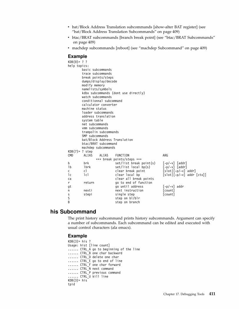
v bat/Block Address Translation subcommands [show-alter BAT register] (see“bat/Block Address Translation Subcommands” on page 409)
v btac/BRAT subcommands [branch break point] (see “btac/BRAT Subcommands”on page 409)
v machdep subcommands [reboot] (see “machdep Subcommand” on page 409)
ExampleKDB(0)> ? ?help topics:
basic subcommandstrace subcommandsbreak points/stepsdumps/display/decodemodify memorynamelists/symbolskdbx subcommands (dont use directly)watch subcommandsconditionnal subcommandcalculator convertermachine statusloader subcommandsaddress translationsystem tablenet subcommandsvmm subcommandstrampolin subcommandsSMP subcommandsbat/Block Address Translationbtac/BRAT subcommandmachdep subcommands
KDB(7)> ? stepCMD ALIAS ALIAS FUNCTION ARG
*** break points/steps ***b brk set/list break point(s) [-p/-v] [addr]lb lbrk set/list local bp(s) [-p/-v] [addr]c cl clear break point [slot|[-p/-v] addr]lc lcl clear local bp [slot|[-p/-v] addr [ctx]]ca clear all break pointsr return go to end of functiongt go until address [-p/-v] addrn nexti next instruction [count]s stepi single step [count]S step on bl/blrB step on branch
his SubcommandThe print history subcommand prints history subcommands. Argument can specifya number of subcommands. Each subcommand can be edited and executed withusual control characters (ala emacs).
ExampleKDB(3)> his ?Usage: hist [line count]...... CTRL_A go to beginning of the line...... CTRL_B one char backward...... CTRL_D delete one char...... CTRL_E go to end of line...... CTRL_F one char forward...... CTRL_N next command...... CTRL_P previous command...... CTRL_U kill lineKDB(3)> histpid
Chapter 17. Debugging Tools 411

fs 11rn 11p proc+001680cdc .kforkx+30 11mw .kforkx+00004048005402.his ?KDB(3)>
e SubcommandThe exit subcommand leaves KDB session and returns to the system, allbreakpoints are installed in memory. To leave KDB without breakpoints, the clearall subcommand must be invoked.
The optional dump argument is only applicable to the KDB kernel debugger.
The dump argument can be specified to force an AIX dump. The method used toforce a dump depends on how the debugger was invoked.
v panic: If the debugger was invoked by the panic call, force the dump byentering q dump. If another processor enters KDB after that (for example:spin-lock timeout), exit the debugger.
v halt_display: If the debugger was invoked by a halt display (C20 on the LED),enter q.
v Soft_reset: If the debugger was invoked by a soft reset (pressing the reset buttonon the server), first move the key on the server. If the key was in the SERVICEposition at boot time, set it to NORMAL; otherwise, set the key to SERVICE.
Note: Forcing a dump with this method requires that you know what thekey position was at boot time.
Then enter quit once for each cpu.
v Break in by |\ : You cannot create a dump if you invoke the debugger with thebreak method.
When the dump is in progress, _0c9 displays on the LEDs while the dump iscopied on disk (either on hd7 or hd6). If you entered the debugger through a paniccall, then control is returned to the debugger when the dump is over, and LEDsshow xxxx. If you entered the debugger through halt_display, the display shows:888 102 700 0c0 when the dump is over.
set SubcommandThe setup subcommand may be used to list and set kdb toggles. Current list oftoggles is:
v no_symbol to suppressed the symbol table management.
v mst_wanted to display all mst items in the stack trace subcommand, every timean interrupt is detected in the stack. To have shorter display, disable this toggle.
v screen_size can be set to change the integrated more window size.
v power_pc_syntax is used in the disassembler package to display old POWER ornew POWER PC instruction mnemonics.
412 Kernel Extensions and Device Support Programming Concepts

v hardware_target is also used in the disassembler package to detect invalidop-code on the specified target. Allowed targets are POWER 601, 603, 604, 620(toggle value: 601, 603, 604, 620) and POWER RS1 RS2 (toggle value: 1, 2).
v unix_symbol_start_from is the lowest effective address from which symbolsearch is started. To force other values to be displayed in hexadecimal, set thisone.
v hexadecimal_wanted applies to thread and proccess subcommand. It is possibleto have information in decimal.
v screen_previous applies to display subcommand. When it is true, the displaysubcommand continues (when typing enter) with decreasing addresses.
v display_stack_frames applies to stack display subcommand. When it is true, thestack display subcommand prints a part of the stack in binary mode.
v display_stacked_regs applies to stack display subcommand. When it is true, thestack display subcommand prints register values saves in the stack.
v 64_bit is used to print 64-bit registers on 64-bit architecture. By default only32-bit formats are printed.
v Thread/Cpu attached local breakpoint (see corresponding part of th document)can be attached to the current thread or the current processor. Choose what youneed. By default, on POWER RS1 it is cpu local, and on POWER PC it is threadlocal.
v Emacs window applies to the display environnement. Under emacs session, setit true to suppress extra line feeds.
v KDB stops all processors is the default behaviour. When KDB is called (frombreak points, panic, control X ...) all processors are stopped, looping until KDBsession is ended. It is possible to let other processors running during a KDBsession by resetting this toggle.
v tweq_r1_r1 indicates that LLDB static break-points are caught by KDB. Set it tofalse and LLDB will be invoked.
v kext_IF_active should be set to enable kernel extension subcommands. Bydefault all subcommands registered by kernel extensions are not parsed.
v trace_back_lookup should be set to process trace back information on user code(text or shared-lib) and kernext code. It can be used to see function names. Bydefault it is not set.
v origin ala LLDB. Sets the origin variable to the value of the specified expression.Origins are used to match addresses with assembly language listings (whichexpress addresses as offsets from the start of the file).
Toggles display_stack_frames and display_stacked_regs can be used to findarguments of routines. Arguments are saved in non-volatile registers or in thecurrent stack. It is an easy way to look for them.
ExampleKDB(1)> setNo toggle name current value1 no_symbol false2 mst_wanted true3 screen_size 244 power_pc_syntax true5 hardware_target 6046 Unix symbols start from 35007 hexadecimal_wanted true8 screen_previous false9 display_stack_frames false
10 display_stacked_regs false11 64_bit false
Chapter 17. Debugging Tools 413

12 emacs_window false13 Thread attached local breakpoint14 KDB stops all processors15 tweq_r1_r1 true16 kext_IF_active true17 kext_IF_active false18 origin 00000000KDB(1)> dw 000034CC display memory000034CC: 00000002 00000008 00010006 00000020KDB(1)> set 6 1000 toggle changeUnix symbols start from 1000KDB(1)> dw 000034CC display memory_system_configuration+000000: 00000002 00000008 00010006 00000020KDB(4)> sw 464Switch to thread: <thread+015C00>KDB(4)> sw u to see user codeKDB(4)> dc 1000A14C1000A14C bl <1000A1A4>KDB(4)> set 17trace_back_lookup is trueKDB(4)> dc 1000A14C.get_superblk+00007C bl <.validate_super>KDB(0)> set origin 002C5338origin = 002C5338KDB(0)> b init_heap1.init_heap1+000000 (real address:002C55F4) permanent & globalKDB(0)> eBreakpoint.init_heap1+000000 (ORG+000002BC) stmw r24,FFFFFFE0(stkp) <.mainstk+001EB8>
r24=00003A60,FFFFFFE0(stkp)=00384B74KDB(0)>In the listing you can see ...
| 000000 PDEF init_heap10| PROC heap_addr,numpages,flags,heapx,pages,gr3-gr80| 0002BC stm BF01FFE0 8 STM #stack(gr1,-32)=gr24-gr31
...
f SubcommandThe stack subcommand displays all the stacks from the current instruction as deepas possible. Interrupts and system calls are crossed and the user stack is also seen.In the user space, trace back allows to have symbolic names. But KDB can notaccess directly these symbols. Use the +x toogle to have binary addresses (byexample, to put a break point on one of these addresses). This toggle is valid until-x is entered with another stack subcommand To have shorter display, you cansuppressed the mst display with the corresponding toggle mst_wanted. To havelonger display, you can set the corresponding toggle display_stack_wanted. It ispossible to display the stack of a specified thread (by its slot entry or address).
If running code is -O compiled, routine parameters are not saved in the stack. KDBwarns about that with [??] at the end of the line. In this case, showed parametersmay be wrong.
ExampleIn the following example, we set a break point on v_gettlock, and when the breakpoint is encountered, the stack is displayed. Then we try to display the firstargument of the open() syscall. Looking at the code, we can see that argument issaved by copen() in register R31, and this register is saved in the stack byopenpath(). Looking at memory pointed by register R31, argument is found:/dev/ptc
KDB(2)> f show the stackthread+012540 STACK:[0004AC84]v_gettlock+000000 (00012049, C0011E80, 00000080, 00000000 [??])
414 Kernel Extensions and Device Support Programming Concepts

[00085C18]v_pregettlock+0000B4 (??, ??, ??, ??)[000132E8]isync_vcs1+0000D8 (??, ??)____ Exception (2FF3B400) ____[000131FC].backt+000000 (00012049, C0011E80 [??])[0004B220]vm_gettlock+000020 (??, ??)[0019A64C]iwrite+00013C (??)[0019D194]finicom+0000A0 (??, ??)[0019D4F0]comlist+0001CC (??, ??)[0019D5BC]_commit+000030 (00000000, 00000001, 09C6E9E8, 399028AA,0000A46F, 0000E2AA, 2D3A4EAA, 2FF3A730)[001E1B18]jfs_setattr+000258 (??, ??, ??, ??, ??, ??)[001A5ED4]vnop_setattr+000018 (??, ??, ??, ??, ??, ??)[001E9008]spec_setattr+00017C (??, ??, ??, ??, ??, ??)[001A5ED4]vnop_setattr+000018 (??, ??, ??, ??, ??, ??)[01B655C8]pty_vsetattr+00002C (??, ??, ??, ??, ??, ??)[01B6584C]pty_setname+000084 (??, ??, ??, ??, ??, ??)[01B60810]pty_create_ptp+0002C4 (??, ??, ??, ??, ??)[01B60210]pty_open_comm+00015C (??, ??, ??, ??)[01B5FFC0]call_pty_open_comm+0000B8 (??, ??, ??, ??)[01B6526C]ptm_open+000140 (??, ??, ??, ??, ??)(2)> more (|C to quit) ?[01A9A124]open_wrapper+0000D0 (??)[01A8DF74]csq_protect+000258 (??, ??, ??, ??, ??, ??)[01A96348]osr_open+0000BC (??)[01A9C1C8]pse_clone_open+000164 (??, ??, ??, ??)[001ADCC8]spec_clone+000178 (??, ??, ??, ??, ??)[001B3FC4]openpnp+0003AC (??, ??, ??, ??, ??)[001B4178]openpath+000064 (??, ??, ??, ??, ??, ??)[001B43E8]copen+000130 (??, ??, ??, ??, ??)[001B44BC]open+000014 (??, ??, ??)[000037D8].sys_call+000000 ()[10002E74]doit+00003C (??, ??, ??)[10003924]main+0004CC (??, ??)[1000014C].__start+00004C ()KDB(2)> set 10 show saved registersdisplay_stacked_regs is trueKDB(2)> f show the stackthread+012540 STACK:[0004AC84]v_gettlock+000000 (00012049, C0011E80, 00000080, 00000000 [??])...[001B3FC4]openpnp+0003AC (??, ??, ??, ??, ??)r24 : 2FF3B6E0 r25 : 2FF3B400 r26 : 10002E78 r27 : 00000000 r28 : 00000002r29 : 2FF3B3C0 r30 : 00000000 r31 : 20000510[001B4178]openpath+000064 (??, ??, ??, ??, ??, ??)[001B43E8]copen+000130 (??, ??, ??, ??, ??)r27 : 2A22A424 r28 : E3014000 r29 : E6012540 r30 : 0C87B000 r31 : 00000000[001B44BC]open+000014 (??, ??, ??)...KDB(2)> dc open 6 look for argument R3.open+000000 stwu stkp,FFFFFFC0(stkp).open+000004 mflr r0.open+000008 addic r7,stkp,38.open+00000C stw r0,48(stkp).open+000010 li r6,0.open+000014 bl <.copen>KDB(2)> dc copen 9 look for argument R3.copen+000000 stmw r27,FFFFFFEC(stkp).copen+000004 addi r28,r4,0.copen+000008 mflr r0.copen+00000C lwz r4,D5C(toc) D5C(toc)=audit_flag.copen+000010 stw r0,8(stkp).copen+000014 stwu stkp,FFFFFFA0(stkp).copen+000018 cmpi cr0,r4,0.copen+00001C mtcrf cr5,r28.copen+000020 addi r31,r3,0KDB(2)> d 20000510 display memory location @R3120000510: 2F64 6576 2F70 7463 0000 0000 416C 6C20 /dev/ptc....All
Chapter 17. Debugging Tools 415

In the following example, the problem is to find what is lsfs subcommand waitingfor. The answer is given with getfssize arguments, and there are saved in thestack.
# ps -ef|grep lsfsroot 63046 39258 0 Apr 01 pts/1 0:00 lsfs# kdbPreserving 587377 bytes of symbol tableFirst symbol sys_resourcePFT:id....................0007raddr.............01000000 eaddr.............B0000000size..............01000000 align.............01000000valid..1 ros....0 holes..0 io.....0 seg....0 wimg...2PVT:id....................0008raddr.............003BC000 eaddr.............B2000000size..............001FFDA0 align.............00001000valid..1 ros....0 holes..0 io.....0 seg....0 wimg...2(0)> dcal 63046 print hexa value of PIDValue decimal: 63046 Value hexa: 0000F646(0)> tpid 0000F646 show threads of this PID
SLOT NAME STATE TID PRI CPUID CPU FLAGS WCHANthread+025440 795 lsfs SLEEP 31B31 03C 000 00000004 057DB5BC(0)> sw 795 set current context on this threadSwitch to thread: <thread+025440>(0)> f show the stackthread+025440 STACK:[000205C0]e_block_thread+000250 ()[00020B1C]e_sleep_thread+000040 (??, ??, ??)[0002AAA0]iowait+00004C (??)[0002B40C]bread+0000DC (??, ??)[0020AF4C]readblk+0000AC (??, ??, ??, ??)[001E90D8]spec_rdwr+00007C (??, ??, ??, ??, ??, ??, ??, ??)[001A6328]vnop_rdwr+000070 (??, ??, ??, ??, ??, ??, ??, ??)[00198278]rwuio+0000CC (??, ??, ??, ??, ??, ??, ??, ??)[001986AC]rdwr+000184 (??, ??, ??, ??, ??, ??)[001984D4]kreadv+000064 (??, ??, ??, ??)[000037D8].sys_call+000000 ()[D0046A18]read+000028 (??, ??, ??)[1000A0E4]get_superblk+000054 (??, ??, ??)[100035F8]read_super+000024 (??, ??, ??, ??)[10005C00]getfssize+0000A0 (??, ??, ??)[10002D18]prnt_stanza+0001E8 (??, ??, ??)[1000349C]do_ls+000294 (??, ??)[10000524]main+0001E8 (??, ??)[1000014C].__start+00004C ()(0)> sw u enable user context of the thread(0)> dc 10005C00-a0 8 look for arguments R3, R4, R510005B60 mflr r010005B64 stw r31,FFFFFFFC(stkp)10005B68 stw r0,8(stkp)10005B6C stwu stkp,FFFFFEE0(stkp)10005B70 stw r3,108(stkp)10005B74 stw r4,104(stkp)10005B78 stw r5,10C(stkp)10005B7C addi r3,r4,0(0)> set 9 print stack framedisplay_stack_frames is true(0)> f show the stackthread+025440 STACK:[000205C0]e_block_thread+000250 ()...[100035F8]read_super+000024 (??, ??, ??, ??)=======================================================================2FF225D0: 2FF2 26F0 2A20 2429 1000 5C04 F071 71C0 /.&.* $)..\..qq.2FF225E0: 2FF2 2620 2000 4D74 D000 4E18 F071 F83C /.& .Mt..N..q. dw
416 Kernel Extensions and Device Support Programming Concepts

2FF225D0+104 print arguments (offset 0x104 0x108 0x10c)2FF226D4: 2000DCC8 2000DC78 00000000 00000004(0)> d 2000DC78 20 print first argument2000DC78: 2F74 6D70 2F73 7472 6970 655F 6673 2E32 /tmp/stripe_fs.22000DC88: 3433 3632 0000 0000 0000 0000 0000 0004 4362............(0)> d 2000DCC8 20 print second argument2000DCC8: 2F64 6576 2F73 6C76 3234 3336 3200 0000 /dev/slv24362...2000DCD8: 0000 0000 0000 0000 0000 0000 0000 0004 ................(0)> q leave debugger#
ctx Subcommand
Note: This subcommand is only available within the kdb command; it is notincluded in the KDB Kernel Debugger.
The context subcommand is used in user mode to analyse memory dump. Bydefault, KDB shows the current AIX context. But it is possible to elect the currentkernel KDB context, and to see more information in stack trace subcommand. Forinstance, the complete stack of a kernel panic is seen. Cpu number is given inargument. No argument allows to restore initial context.
Note: KDB context is available only if the running kernel is booted with KDB.
Example$ kdb dump unix dump analysisPreserving 628325 bytes of symbol tableFirst symbol sys_resourceComponent Names:1) proc2) thrd3) errlg4) bos5) vmm6) bscsi7) scdisk8) lvm9) tty10) netstat11) lent_ddPFT:id....................0007raddr.....0000000001000000 eaddr.....0000000001000000size..............00800000 align.............00800000valid..1 ros....0 holes..0 io.....0 seg....1 wimg...2PVT:id....................0008raddr.....00000000004B8000 eaddr.....00000000004B8000size..............000FFD60 align.............00001000valid..1 ros....0 holes..0 io.....0 seg....1 wimg...2Dump analysis on POWER_PC POWER_604 machine with 8 cpu(s)Processing symbol table..........................done(0)> stat machine statusRS6K_SMP_MCA POWER_PC POWER_604 machine with 8 cpu(s).......... SYSTEM STATUSsysname... AIX nodename.. jumbo32release... 3 version... 4machine... 00920312A0 nid....... 920312A0time of crash: Tue Jul 22 09:46:22 1997age of system: 1 day, 0 min., 35 sec........... PANIC STRINGassert(v_lookup(sid,pno) == -1).......... SYSTEM MESSAGES
Chapter 17. Debugging Tools 417
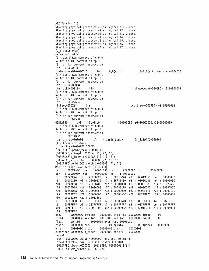
AIX Version 4.3Starting physical processor #1 as logical #1... done.Starting physical processor #2 as logical #2... done.Starting physical processor #3 as logical #3... done.Starting physical processor #4 as logical #4... done.Starting physical processor #5 as logical #5... done.Starting physical processor #6 as logical #6... done.Starting physical processor #7 as logical #7... done.[v_lists.c #727]<- end_of_buffer(0)> ctx 0 KDB context of CPU 0Switch to KDB context of cpu 0(0)> dr iar current instructioniar : 00009414.unlock_enable+000110 lwz r0,8(stkp) r0=0,8(stkp)=mststack+00AD18(0)> ctx 1 KDB context of CPU 1Switch to KDB context of cpu 1(1)> dr iar current instructioniar : 000BDB68.kunlockl+000118 blr <.ld_usecount+0005BC> r3=0000000B(1)> ctx 2 KDB context of CPU 2Switch to KDB context of cpu 2(2)> dr iar current instructioniar : 00027634.tstart+000284 blr <.sys_timer+000964> r3=00000005(2)> ctx 3 KDB context of CPU 3Switch to KDB context of cpu 3(3)> dr iar current instructioniar : 01B6A58001B6A580 ori r3,r31,0 <00000089> r3=50001000,r31=00000089(3)> ctx 4 KDB context of CPU 4Switch to KDB context of cpu 4(4)> dr iar current instructioniar : 00014BFC.panic_trap+000004 bl <.panic_dump> r3=_$STATIC+000294(4)> f current stack__kdb_thread+0002F0 STACK:[00014BFC].panic_trap+000004 ()[0003ACAC]v_inspft+000104 (??, ??, ??)[00048DA8]v_inherit+0004A0 (??, ??, ??)[000A7ECC]v_preinherit+000058 (??, ??, ??)[00027BFC]begbt_603_patch_2+000008 (??, ??)Machine State Save Area [2FF3B400]iar : 00027AEC msr : 000010B0 cr : 22222222 lr : 00243E58ctr : 00000000 xer : 00000000 mq : 00000000r0 : 000A7E74 r1 : 2FF3B220 r2 : 002EBC70 r3 : 00013350 r4 : 00000000r5 : 00000100 r6 : 00009030 r7 : 2FF3B400 r8 : 00000106 r9 : 00000000r10 : 00243E58 r11 : 2FF3B400 r12 : 000010B0 r13 : 000C1C80 r14 : 2FF22A88r15 : 20022DB8 r16 : 20006A98 r17 : 20033128 r18 : 00000000 r19 : 0008AD56r20 : B02A6038 r21 : 0000006A r22 : 00000000 r23 : 0000FFFF r24 : 00000100r25 : 00003262 r26 : 00000000 r27 : B02B8AEC r28 : B02A9F70 r29 : 00000001r30 : 00003350 r31 : 00013350s0 : 00000000 s1 : 007FFFFF s2 : 0000864B s3 : 007FFFFF s4 : 007FFFFFs5 : 007FFFFF s6 : 007FFFFF s7 : 007FFFFF s8 : 007FFFFF s9 : 007FFFFFs10 : 007FFFFF s11 : 00001001 s12 : 00002002 s13 : 6001F01F s14 : 00004004s15 : 007FFFFFprev 00000000 kjmpbuf 00000000 stackfix 00000000 intpri 0Bcurid 0008AD56 sralloc E01E0000 ioalloc 00000000 backt 00flags 00 tid 00000000 excp_type 00000000fpscr 00000000 fpeu 01 fpinfo 00 fpscrx 00000000o_iar 00000000 o_toc 00000000 o_arg1 00000000excbranch 00000000 o_vaddr 00000000 mstext 00000000Except :csr 00000000 dsisr 40000000 bit set: DSISR_PFTsrval 6000864B dar 2FF22FF8 dsirr 00000106[00027AEC].backt+000000 (00013350, 00000000 [??])[00243E54]vms_delete+0004DC (??)
418 Kernel Extensions and Device Support Programming Concepts

[00256838]shmfreews+0000B0 ()[000732B4]freeuspace+000010 ()[00072EAC]kexitx+000688 (??)(4)> ctx AIX context of CPU 4Restore initial context(4)> f current stackthread+031920 STACK:[00027AEC].backt+000000 (00013350, 00000000 [??])[00243E54]vms_delete+0004DC (??)[00256838]shmfreews+0000B0 ()[000732B4]freeuspace+000010 ()[00072EAC]kexitx+000688 (??)(4)>
cdt Subcommand
Note: This subcommand is only available within the kdb command; it is notincluded in the KDB Kernel Debugger.
The cdt subcommand is used in user mode to analyse memory dump. Any part ofcomponent dump can be printed. Usage is cdt [-d] [<index>] [<entry>].
v -d to ask for data dump
v index of the component in the table
v entry of the data area in the component
Example(0)> cdt1) CDT head name proc, len 001D80E8, entries 966762) CDT head name thrd, len 003ABE4C, entries 1924893) CDT head name errlg, len 00000054, entries 34) CDT head name bos, len 00000040, entries 25) CDT head name vmm, len 000003D8, entries 306) CDT head name sscsidd, len 0000007C, entries 57) CDT head name dptSR, len 00000054, entries 38) CDT head name scdisk, len 00000130, entries 149) CDT head name lvm, len 00000040, entries 210) CDT head name SSAGS, len 000000A4, entries 711) CDT head name SSAES, len 00000054, entries 312) CDT head name ssagateway, len 0000007C, entries 513) CDT head name tty, len 00000068, entries 414) CDT head name sio_dd, len 00000054, entries 315) CDT head name netstat, len 000000E0, entries 1016) CDT head name ent2104x, len 00000054, entries 317) CDT head name cstokdd, len 0000007C, entries 518) CDT head name atm_dd_charm, len 00000040, entries 219) CDT head name ssadisk, len 000002AC, entries 3320) CDT head name SSADS, len 00000040, entries 221) CDT head name osi_frame, len 0000002C, entries 1(0)> cdt 1212) CDT head name ssagateway, len 0000007C, entries 5CDT 1 name HashTbl addr 0000000001A25CF0, len 00000040CDT 2 name CfgdAdap addr 0000000001A0E044, len 00000004CDT 3 name OpenAdap addr 0000000001A0E048, len 00000004CDT 4 name LockWord addr 0000000001A0E04C, len 00000004CDT 5 name ssa0 addr 0000000001A2D000, len 00000B88(0)> cdt -d 12 412) CDT head name ssagateway, len 0000007C, entries 5CDT 4 name LockWord addr 0000000001A0E04C, len 0000000401A0E04C: FFFFFFFF ....
Chapter 17. Debugging Tools 419
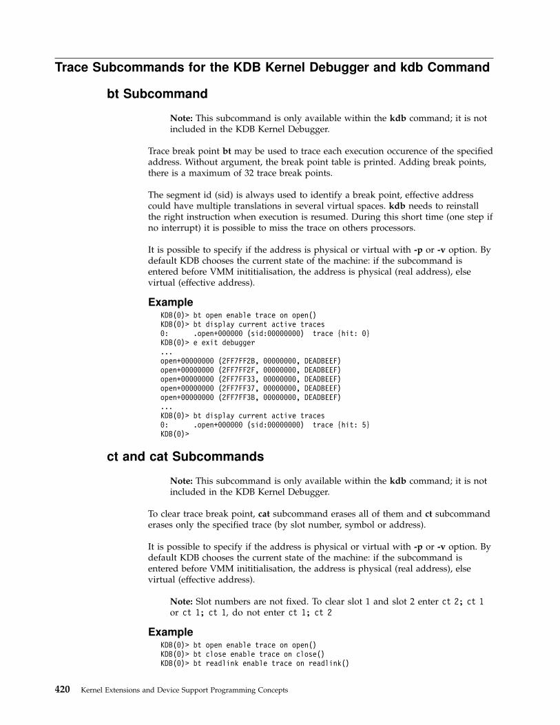
Trace Subcommands for the KDB Kernel Debugger and kdb Command
bt Subcommand
Note: This subcommand is only available within the kdb command; it is notincluded in the KDB Kernel Debugger.
Trace break point bt may be used to trace each execution occurence of the specifiedaddress. Without argument, the break point table is printed. Adding break points,there is a maximum of 32 trace break points.
The segment id (sid) is always used to identify a break point, effective addresscould have multiple translations in several virtual spaces. kdb needs to reinstallthe right instruction when execution is resumed. During this short time (one step ifno interrupt) it is possible to miss the trace on others processors.
It is possible to specify if the address is physical or virtual with -p or -v option. Bydefault KDB chooses the current state of the machine: if the subcommand isentered before VMM inititialisation, the address is physical (real address), elsevirtual (effective address).
ExampleKDB(0)> bt open enable trace on open()KDB(0)> bt display current active traces0: .open+000000 (sid:00000000) trace {hit: 0}KDB(0)> e exit debugger...open+00000000 (2FF7FF2B, 00000000, DEADBEEF)open+00000000 (2FF7FF2F, 00000000, DEADBEEF)open+00000000 (2FF7FF33, 00000000, DEADBEEF)open+00000000 (2FF7FF37, 00000000, DEADBEEF)open+00000000 (2FF7FF3B, 00000000, DEADBEEF)...KDB(0)> bt display current active traces0: .open+000000 (sid:00000000) trace {hit: 5}KDB(0)>
ct and cat Subcommands
Note: This subcommand is only available within the kdb command; it is notincluded in the KDB Kernel Debugger.
To clear trace break point, cat subcommand erases all of them and ct subcommanderases only the specified trace (by slot number, symbol or address).
It is possible to specify if the address is physical or virtual with -p or -v option. Bydefault KDB chooses the current state of the machine: if the subcommand isentered before VMM inititialisation, the address is physical (real address), elsevirtual (effective address).
Note: Slot numbers are not fixed. To clear slot 1 and slot 2 enter ct 2; ct 1or ct 1; ct 1, do not enter ct 1; ct 2
ExampleKDB(0)> bt open enable trace on open()KDB(0)> bt close enable trace on close()KDB(0)> bt readlink enable trace on readlink()
420 Kernel Extensions and Device Support Programming Concepts

KDB(0)> bt display current active traces0: .open+000000 (sid:00000000) trace {hit: 0}1: .close+000000 (sid:00000000) trace {hit: 0}2: .readlink+000000 (sid:00000000) trace {hit: 0}KDB(0)> ct 1 clear trace slot 1KDB(0)> bt display current active traces0: .open+000000 (sid:00000000) trace {hit: 0}1: .readlink+000000 (sid:00000000) trace {hit: 0}KDB(0)> cat clear all active tracesKDB(0)> bt display current active tracesNo breakpoints are set.KDB(0)>
bt script SubcommandBy default the top of the stack is displayed, but it is possible to specified a scriptof kdb subcommands. These subcommands are executed when the trace breakpoint is hit.
ExampleOpen routine is traced with a script asking to display iar and lr registers and toshow what is pointed by r3, the first parameter. Here open() is called on ″sbin″
from svc_flih().
KDB(0)> bt open "dr iar; dr lr; d @r3" enable trace on open()KDB(0)> bt display current active traces0: .open+000000 (sid:00000000) trace {hit: 0} {script: dr iar; dr lr;d @r3}KDB(0)> e exit debuggeriar : 001C5BA0.open+000000 mflr r0 <.svc_flih+00011C>lr : 00003B34.svc_flih+00011C lwz toc,4108(0) toc=TOC,4108=g_toc2FF7FF3F: 7362 696E 0074 6D70 0074 6F74 6F00 7500 sbin.tmp.toto.u.KDB(0)> bt display current active traces0: .open+000000 (sid:00000000) trace {hit: 1} {script: dr iar; dr lr;d @r3}KDB(0)> ct open clear trace on openKDB(0)>
bt [ cond ] SubcommandWith a conditionnal subcommand, it is possible to stop inside kdb when thecondition is true.
ExampleThis example shows how to trace and stop when a condition is true. Here we arewaiting for time global data to be greater than the specified value, and 923 hitshave been necessary to win.
KDB(0)> bt sys_timer "[ @time >= 2b8c8c00 ] " enable trace on sys_timer()KDB(0)> e exit debugger...Enter kdb [ @time >= 2b8c8c00 ]KDB(0)> bt display current active traces0: .sys_timer+000000 (sid:00000000) trace {hit: 923} {script: [ @time >= 2b8c8c00 ] }KDB(0)> cat clear all traces
Breakpoints/Steps Subcommands for the KDB Kernel Debugger and
kdb Command
b Subcommand
Note: This subcommand is only available within the kdb command; it is notincluded in the KDB Kernel Debugger.
Chapter 17. Debugging Tools 421
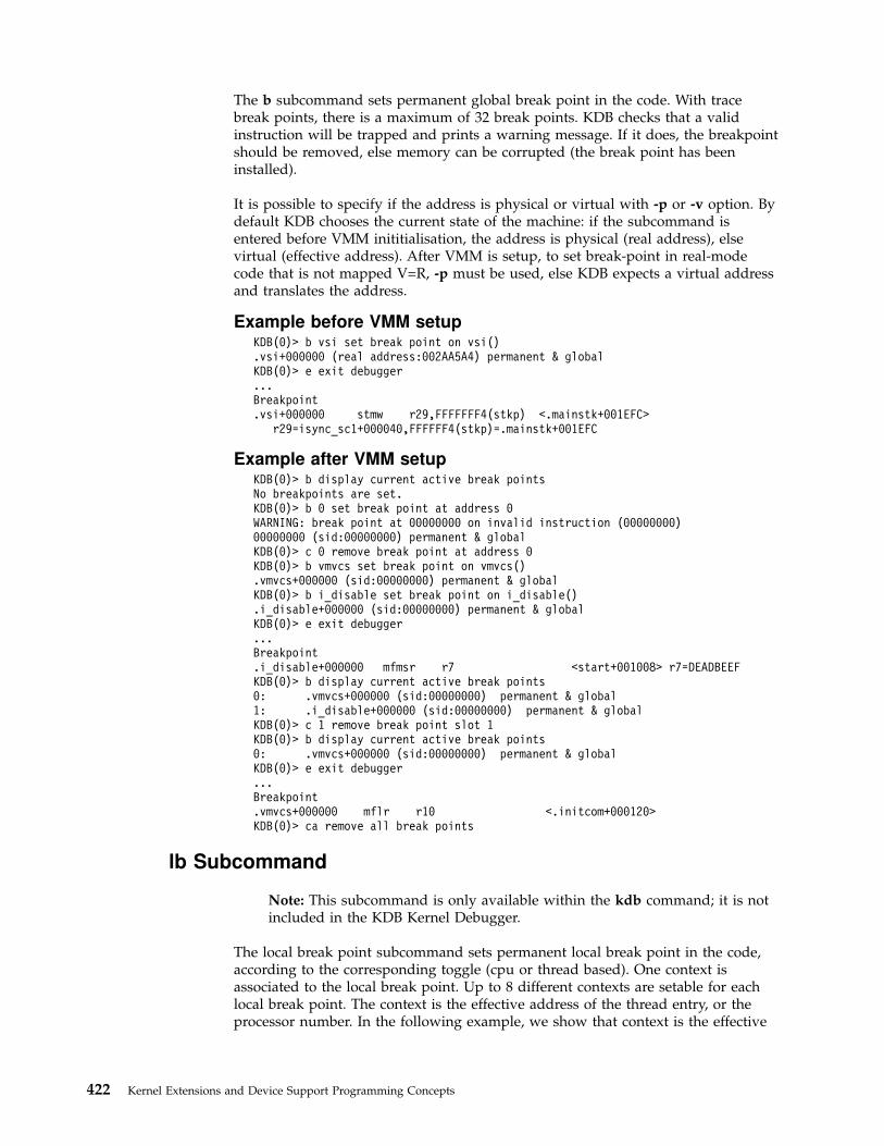
The b subcommand sets permanent global break point in the code. With tracebreak points, there is a maximum of 32 break points. KDB checks that a validinstruction will be trapped and prints a warning message. If it does, the breakpointshould be removed, else memory can be corrupted (the break point has beeninstalled).
It is possible to specify if the address is physical or virtual with -p or -v option. Bydefault KDB chooses the current state of the machine: if the subcommand isentered before VMM inititialisation, the address is physical (real address), elsevirtual (effective address). After VMM is setup, to set break-point in real-modecode that is not mapped V=R, -p must be used, else KDB expects a virtual addressand translates the address.
Example before VMM setupKDB(0)> b vsi set break point on vsi().vsi+000000 (real address:002AA5A4) permanent & globalKDB(0)> e exit debugger...Breakpoint.vsi+000000 stmw r29,FFFFFFF4(stkp) <.mainstk+001EFC>
r29=isync_sc1+000040,FFFFFF4(stkp)=.mainstk+001EFC
Example after VMM setupKDB(0)> b display current active break pointsNo breakpoints are set.KDB(0)> b 0 set break point at address 0WARNING: break point at 00000000 on invalid instruction (00000000)00000000 (sid:00000000) permanent & globalKDB(0)> c 0 remove break point at address 0KDB(0)> b vmvcs set break point on vmvcs().vmvcs+000000 (sid:00000000) permanent & globalKDB(0)> b i_disable set break point on i_disable().i_disable+000000 (sid:00000000) permanent & globalKDB(0)> e exit debugger...Breakpoint.i_disable+000000 mfmsr r7 <start+001008> r7=DEADBEEFKDB(0)> b display current active break points0: .vmvcs+000000 (sid:00000000) permanent & global1: .i_disable+000000 (sid:00000000) permanent & globalKDB(0)> c 1 remove break point slot 1KDB(0)> b display current active break points0: .vmvcs+000000 (sid:00000000) permanent & globalKDB(0)> e exit debugger...Breakpoint.vmvcs+000000 mflr r10 <.initcom+000120>KDB(0)> ca remove all break points
lb Subcommand
Note: This subcommand is only available within the kdb command; it is notincluded in the KDB Kernel Debugger.
The local break point subcommand sets permanent local break point in the code,according to the corresponding toggle (cpu or thread based). One context isassociated to the local break point. Up to 8 different contexts are setable for eachlocal break point. The context is the effective address of the thread entry, or theprocessor number. In the following example, we show that context is the effective
422 Kernel Extensions and Device Support Programming Concepts

address of the curthread. Local break points are cleared context by context with thelc subcommand. By default the current context is cleared. The c or ca subcommandclears all contexts.
When the break point is hit with another context, KDB prints a warning. Usingswitch subcommand, it is possible to select another context, instead ofthe currentone. After switching from the current context (thread or processor) to another one,the lb subcommand will apply on this new context.
It is possible to specify if the address is physical or virtual with -p or -v option. Bydefault KDB chooses the current state of the machine: if the subcommand isentered before VMM inititialisation, the address is physical (real address), elsevirtual (effective address). After VMM is setup, to set break-point in real-modecode that is not mapped V=R, -p must b used, else KDB expects a virtual addressand translates the address.
ExampleKDB(0)> b execv set break point on execv()Assumed to be [External data]: 001F4200 execveAmbiguous: [Ext func]001F4200 .execve.execve+000000 (sid:00000000) permanent & globalKDB(0)> e exit debugger...Breakpoint.execve+000000 mflr r0 <.svc_flih+00011C>KDB(0)> ppda print current processor data areaPer Processor Data Area [00086E40]csa......................2FEE0000 mstack...................0037CDB0fpowner..................00000000 curthread................E60008C0...KDB(0)> lb kexit set local break point on kexit().kexit+000000 (sid:00000000) permanent & localKDB(0)> b display current active break points0: .execve+000000 (sid:00000000) permanent & global1: .kexit+000000 (sid:00000000) permanent & localKDB(0)> e exit debugger...Warning, breakpoint ignored (context mismatched):.kexit+000000 mflr r0 <._exit+000020>Breakpoint.kexit+000000 mflr r0 <._exit+000020>KDB(0)> ppda print current processor data areaPer Processor Data Area [00086E40]csa......................2FEE0000 mstack...................0037CDB0fpowner..................00000000 curthread................E60008C0...KDB(0)> lc 1 thread+0008C0 remove local break point slot 1
c, lc, and ca Subcommands
Note: This subcommand is only available within the kdb command; it is notincluded in the KDB Kernel Debugger.
To clear break point, use one of these subcommands. cat subcommand erases all ofthem: global, local, permanent or not. c and lc subcommand erase only thespecified break point (by slot number, symbol or address). With lc subcommand,by default first context is removed. If there are more t one context, it is possible tospecify the context to be removed.
Chapter 17. Debugging Tools 423

It is possible to specify if the address is physical or virtual with -p or -v option. Bydefault KDB chooses the current state of th machine: if the subcommand is enteredbefore VMM inititialisation, the address is physical (real address), else virtual(effective address). After VMM is setup, to set break-point in real-mode code thatis not mapped V=R, -p must be used, else KDB expects a virtual address andtranslates the address.
Note: Slot numbers are not fixed. To clear slot 1 and slot 2 enter ct 2; ct 1or ct 1; ct 1, do not enter ct 1; ct 2
r and gt Subcommands
Note: This subcommand is only available within the kdb command; it is notincluded in the KDB Kernel Debugger.
Non permanent break point can be set by the go to address subcommands. In thatcase it is local break points, and when KDB is entered, this break point is cleared.The r subcommand sets a break point on the address found in the lr register. InSMP environnement, it is possible to hit this break point on another processor, so itis important to have thread/process local break point.
The gt subcommand has the same effect but we precise the wanted address.
It is possible to specify if the address is physical or virtual with -p or -v option. Bydefault KDB chooses the current state of the machine: if the subcommand isentered before VMM inititialisation, the address is physical (real address), elsevirtual (effective address). After VMM is setup, to set break-point in real-modecode that is not mapped V=R, -p must be used, else KDB expects a virtual addressand translates the address.
When the break point is hit with another context, KDB prints a warning.
ExampleKDB(2)> b _iput enable break point on _iput()._iput+000000 (sid:00000000) permanent & globalKDB(2)> e exit debugger...Breakpoint._iput+000000 stmw r29,FFFFFFF4(stkp) <2FF3B1CC>
r29=0A4C6C20,FFFFFFF4(stkp)=2FF3B1CCKDB(6)> fthread+014580 STACK:[0021632C]_iput+000000 (0A4C6C20, 0571A808 [??])[00263EF4]jfs_rele+0000B4 (??)[00220B58]vnop_rele+000018 (??)[00232178]vno_close+000058 (??)[002266C8]closef+0000C8 (??)[0020C548]closefd+0000BC (??, ??)[0020C70C]close+000174 (??)[000037C4].sys_call+000000 ()[D000715C]fclose+00006C (??)[10000580]10000580+000000 ()[10000174]__start+00004C ()KDB(6)> r go to the end of the function....jfs_rele+0000B8 b <.jfs_rele+00007C> r3=0KDB(7)> e exit debugger...Breakpoint._iput+000000 stmw r29,FFFFFFF4(stkp) <2FF3B24C>
424 Kernel Extensions and Device Support Programming Concepts

r29=09D75BD0,FFFFFFF4(stkp)=2FF3B24CKDB(3)> gt @lr go to the link register value.jfs_rele+0000B8 (sid:00000000) step....jfs_rele+0000B8 b <.jfs_rele+00007C> r3=0KDB(1)>
n s, S, and B Subcommands
Note: This subcommand is only available within the kdb command; it is notincluded in the KDB Kernel Debugger.
Step can be done by two subcommands. The s subcommand allows the processorto single step on the next instruction. The n subcommand causes step to skip oversubroutine calls, and we can follow the main flow of control. A count may specifyhow many steps are executed before returning to KDB dialog. Enter CR/LF andKDB continues the last step subcommand.
The S subcommand single steps but stops only on bl and br instructions. Withthat, we can see every call and return of routines. A count is also used to specifyhow many times KDB continues before stopping, and CR/LF continues the lastsubcommand
On POWER RS1 machine, steps are implemented with non permanent local breakpoints. On POWER PC machine, steps are implemented with the SE bit of the msrstatus register of the processor. This bit is automatically associated with thethread/process context and can migrate from one processor to another.
A too long step subcommand can be interrupted by typing DEL key. Every timeKDB treats a step occurence, DEL key is tested.
Be aware that when you single step a program, this makes an exception to theprocessor for each of the debugged program’s instruction. One side-effect ofexceptions is to break reservations (see POWER PC architecture). This is why stcwxnever succeeds if any breakpoint occurred since the last larwx. The net effect is thatlock and atomic routines are not steppable. If you do it anyway, the system does notbreak, but you loop in the lock routine. If that happens, just ″return″ from the lockroutine to the caller, and if the lock is free, you can get it.
Be aware also that some instructions are broken by exceptions. For examples, rfi,move to-from srr0 srr1. KDB tries to prevent against that by printing a warningmessage.
Note that the S subcommand of KDB (which single-steps the program until thenext sub-routine call/return) will silently and endlessly fail to go through theatomic/lock routines. To watch out for this, you will get the KDB prompt againwith a warning message.
When you want to take control of a thread currently sleeping, it is possible to stepin the context of this thread. To do that you just have to switch to the sleepingthread (with sw subcommand) and to type the s subcommand. The step is setinside the thread context, and when the thread runs again, the step break pointoccurs.
Chapter 17. Debugging Tools 425

ExampleKDB(1)> b .vno_close+00005C enable break point on vno_close+00005Cvno_close+00005C (sid:00000000) permanent & globalKDB(1)> e exit debuggerBreakpoint.vno_close+00005C lwz r11,30(r4) r11=0,30(r4)=xix_vops+000030KDB(1)> s 10 single step 10 instructions.vno_close+000060 lwz r5,68(stkp) r5=FFD00000,68(stkp)=2FF97DD0.vno_close+000064 lwz r4,0(r5) r4=xix_vops,0(r5)=file+0000C0.vno_close+000068 lwz r5,14(r5) r5=file+0000C0,14(r5)=file+0000D4.vno_close+00006C bl <._ptrgl> r3=05AB620C._ptrgl+000000 lwz r0,0(r11) r0=.closef+0000F4,0(r11)=xix_close._ptrgl+000004 stw toc,14(stkp) toc=TOC,14(stkp)=2FF97D7C._ptrgl+000008 mtctr r0 <.xix_close+000000>._ptrgl+00000C lwz toc,4(r11) toc=TOC,4(r11)=xix_close+000004._ptrgl+000010 lwz r11,8(r11) r11=xix_close,8(r11)=xix_close+000008._ptrgl+000014 bcctr <.xix_close>KDB(1)> <CR/LF> repeat last single step command.xix_close+000000 mflr r0 <.vno_close+000070>.xix_close+000004 stw r31,FFFFFFFC(stkp) r31=_vno_fops$$,FFFFFFFC(stkp)=2FF97D64.xix_close+000008 stw r0,8(stkp) r0=.vno_close+000070,8(stkp)=2FF97D70.xix_close+00000C stwu stkp,FFFFFFA0(stkp) stkp=2FF97D68,FFFFFFA0(stkp)=2FF97D08.xix_close+000010 lwz r31,12B8(toc) r31=_vno_fops$$,12B8(toc)=_xix_close$$.xix_close+000014 stw r3,78(stkp) r3=05AB620C,78(stkp)=2FF97D80.xix_close+000018 stw r4,7C(stkp) r4=00000020,7C(stkp)=2FF97D84.xix_close+00001C lwz r3,12BC(toc) r3=05AB620C,12BC(toc)=xclosedbg.xix_close+000020 lwz r3,0(r3) r3=xclosedbg,0(r3)=xclosedbg.xix_close+000024 lwz r4,12C0(toc) r4=00000020,12C0(toc)=pfsdbgKDB(1)> r return to the end of function.vno_close+000070 lwz toc,14(stkp) toc=TOC,14(stkp)=2FF97D7CKDB(1)> S 4.vno_close+000088 bl <._ptrgl> r3=05AB620C.xix_rele+00010C bl <.vn_free> r3=05AB620C.vn_free+000140 bl <.gpai_free> r3=gpa_vnode.gpai_free+00002C br <.vn_free+000144>KDB(1)> <CR/LF> repeat last command.vn_free+00015C br <.xix_rele+000110>.xix_rele+000118 bl <.iput> r3=058F9360.iput+0000A4 bl <.iclose> r3=058F9360.iclose+000148 br <.iput+0000A8>KDB(1)> <CR/LF> repeat last command.iput+0001A4 bl <.insque2> r3=058F9360.insque2+00004C br <.iput+0001A8>.iput+0001D0 br <.xix_rele+00011C>.xix_rele+000164 br <.vno_close+00008C>KDB(1)> r return to the end of function.vno_close+00008C lwz toc,14(stkp) toc=TOC,14(stkp)=2FF97D7CKDB(1)>
Dumps/Display/Decode Subcommands for the KDB Kernel Debugger
and kdb Command
d, dw, dd, dp, dpw, dpd SubcommandsGenerally speaking, the display memory subcommands allow read or write accessto be done in virtual or real mode, using an effective address or a real address asinput:
v d subcommands: real mode access with an effective address as argument.
v dp subcommands: real mode access with a real address as argument.
v ddv subcommands: virtual mode access with an effective address as argument.
v ddp subcommands: virtual mode access with a real address as argument.
426 Kernel Extensions and Device Support Programming Concepts

The d (display bytes) dw (display words) dd (display double words)subcommands may be used to dump memory areas, specified address is aneffective address. Access is done in real mode.
The dp (display bytes) dpw (display words) dpd (display double words)subcommands may be used to dump memory areas, specified address is a realaddress.
Count argument is in hexadecimal base for display data, so 10 bytes is one lineand 10 words is 4 lines. To display from symbol to symbol+0080 the subcommandis d symbol 80 or dw symbol 20
Default count is one line, and <CR/LF> continues display.
ExampleKDB(0)> d utsname 40 print utsname byte per byteutsname+000000: 4149 5820 0000 0000 0000 0000 0000 0000 AIX.............utsname+000010: 0000 0000 0000 0000 0000 0000 0000 0000 ................utsname+000020: 3030 3030 3030 3030 4130 3030 0000 0000 00000000A000....utsname+000030: 0000 0000 0000 0000 0000 0000 0000 0000 ................KDB(0)> <CR/LF> repeat last commandutsname+000040: 3100 0000 0000 0000 0000 0000 0000 0000 1...............utsname+000050: 0000 0000 0000 0000 0000 0000 0000 0000 ................utsname+000060: 3400 0000 0000 0000 0000 0000 0000 0000 4...............utsname+000070: 0000 0000 0000 0000 0000 0000 0000 0000 ................KDB(0)> <CR/LF> repeat last commandutsname+000080: 3030 3030 3030 3030 4130 3030 0000 0000 00000000A000....utsname+000090: 0000 0000 0000 0000 0000 0000 0000 0000 ................xutsname+000000: 0000 0000 0000 0000 0000 0000 0000 0000 ................devcnt+000000: 0000 0100 0000 0000 0001 239C 0001 23A8 ..........#...#.KDB(0)> dw utsname 10 print utsname word per wordutsname+000000: 41495820 00000000 00000000 00000000 AIX.............utsname+000010: 00000000 00000000 00000000 00000000 ................utsname+000020: 30303030 30303030 41303030 00000000 00000000A000....utsname+000030: 00000000 00000000 00000000 00000000 ................KDB(0)> tr utsname find utsname physical addressPhysical Address = 00027E98KDB(0)> dp 00027E98 40 print utsname using physical address00027E98: 4149 5820 0000 0000 0000 0000 0000 0000 AIX.............00027EA8: 0000 0000 0000 0000 0000 0000 0000 0000 ................00027EB8: 3030 3030 3030 3030 4130 3030 0000 0000 00000000A000....00027EC8: 0000 0000 0000 0000 0000 0000 0000 0000 ................KDB(0)> dpw 00027E98 print utsname using physical address00027E98: 41495820 00000000 00000000 00000000 AIX.............KDB(0)>
dc and dpc SubcommandsThe display code subcommands may be used to decode instructions.
Breakpoints are not seen, KDB prints the real instruction.
ExampleKDB(0)> set 4 set toggle for Power PC syntaxpower_pc_syntax is trueKDB(0)> dc resume_pc 10 prints 10 instructions.resume_pc+000000 lbz r0,3454(0) 3454=Trconflag.resume_pc+000004 mfsprg r15,0.resume_pc+000008 cmpi cr0,r0,0.resume_pc+00000C lwz toc,4208(0) toc=TOC,4208=g_toc.resume_pc+000010 lwz r30,4C(r15).resume_pc+000014 lwz r14,40(r15).resume_pc+000018 lwz r31,8(r30)
Chapter 17. Debugging Tools 427

.resume_pc+00001C bne- cr0.eq,<.resume_pc+0001BC>
.resume_pc+000020 lha r28,2(r30)
.resume_pc+000024 lwz r29,0(r14)KDB(0)> dc mttb 5 prints mttb function.mttb+000000 li r0,0.mttb+000004 mttbl X r0 X shows that these instructions.mttb+000008 mttbu X r3 are not supported by the current architecture.mttb+00000C mttbl X r4 POWER PC 601 processor.mttb+000010 blrKDB(0)> set 4 set toggle for Power RS syntaxpower_pc_syntax is falseKDB(0)> dc resume_pc 10 prints 10 instructions.resume_pc+000000 lbz r0,3454(0) 3454=Trconflag.resume_pc+000004 mfspr r15,110.resume_pc+000008 cmpi cr0,r0,0.resume_pc+00000C l toc,4208(0) toc=TOC,4208=g_toc.resume_pc+000010 l r30,4C(r15).resume_pc+000014 l r14,40(r15).resume_pc+000018 l r31,8(r30).resume_pc+00001C bne cr0.eq,<.resume_pc+0001BC>.resume_pc+000020 lha r28,2(r30).resume_pc+000024 l r29,0(r14)KDB(4)> dc scdisk_pm_handler.scdisk_pm_handler+000000 stmw r26,FFFFFFE8(stkp)KDB(4)> tr scdisk_pm_handlerPhysical Address = 1D7CA1C0KDB(4)> dpc 1D7CA1C01D7CA1C0 stmw r26,FFFFFFE8(stkp)
dr SubcommandThe display registers subcommand may be used to display general purpose,segment or special registers. The current context is used to find values. Afterswitching from current thread to another one, KDB shows registers of the new one.
For BATs registers (see “bat/Block Address Translation Subcommands” onpage 409), dbat and ibat subcommands must be used.
ExampleKDB(0)> dr ? print usageis not a valid register name
Usage: dr [sp|sr|gp|fp|<reg. name>]sp reg. name: iar msr cr lr ctr xer mq tid asr............. dsisr dar dec sdr0 sdr1 srr0 srr1 dabr rtcu rtcl............. tbu tbl sprg0 sprg1 sprg2 sprg3 pir fpecr ear pvr............. hid0 hid1 iabr dmiss imiss dcmp icmp hash1 hash2 rpa............. buscsr l2cr l2sr mmcr0 mmcr1 pmc1 pmc2 pmc3 pmc4 pmc5............. pmc6 pmc7 pmc8 sia sdasr reg. name: s0 s1 s2 s3 s4 s5 s6 s7 s8 s9............. s10 s11 s12 s13 s14 s15gp reg. name: r0 r1 r2 r3 r4 r5 r6 r7 r8 r9............. r10 r11 r12 r13 r14 r15 r16 r17 r18 r19............. r20 r21 r22 r23 r24 r25 r26 r27 r28 r29............. r30 r31fp reg. name: f0 f1 f2 f3 f4 f5 f6 f7 f8 f9............. f10 f11 f12 f13 f14 f15 f16 f17 f18 f19............. f20 f21 f22 f23 f24 f25 f26 f27 f28 f29............. f30 f31 fpscrKDB(0)> dr print general purpose registersr0 : 00003730 r1 : 2FEDFF88 r2 : 00211B6C r3 : 00000000 r4 : 00000003r5 : 007FFFFF r6 : 0002F930 r7 : 2FEAFFFC r8 : 00000009 r9 : 20019CC8r10 : 00000008 r11 : 00040B40 r12 : 0009B700 r13 : 2003FC60 r14 : DEADBEEFr15 : 00000000 r16 : DEADBEEF r17 : 2003FD28 r18 : 00000000 r19 : 20009168r20 : 2003FD38 r21 : 2FEAFF3C r22 : 00000001 r23 : 2003F700 r24 : 2FEE02E0r25 : 2FEE0000 r26 : D0005454 r27 : 2A820846 r28 : E3000E00 r29 : E60008C0
428 Kernel Extensions and Device Support Programming Concepts
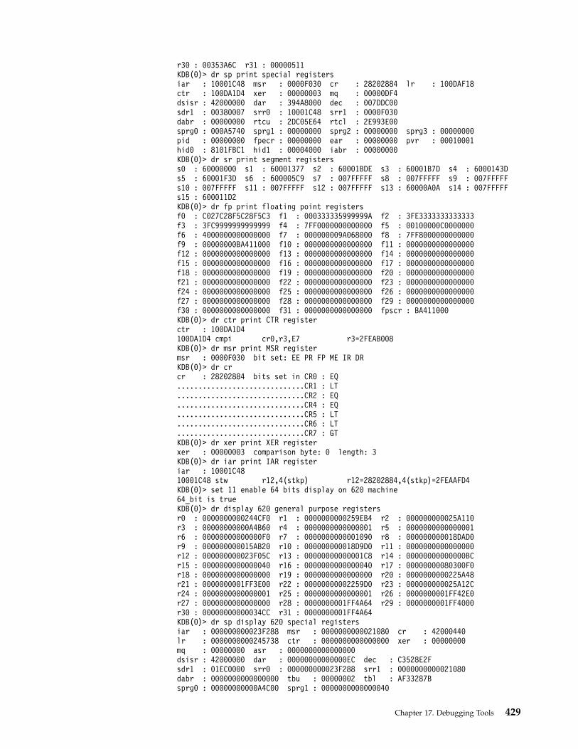
r30 : 00353A6C r31 : 00000511KDB(0)> dr sp print special registersiar : 10001C48 msr : 0000F030 cr : 28202884 lr : 100DAF18ctr : 100DA1D4 xer : 00000003 mq : 00000DF4dsisr : 42000000 dar : 394A8000 dec : 007DDC00sdr1 : 00380007 srr0 : 10001C48 srr1 : 0000F030dabr : 00000000 rtcu : 2DC05E64 rtcl : 2E993E00sprg0 : 000A5740 sprg1 : 00000000 sprg2 : 00000000 sprg3 : 00000000pid : 00000000 fpecr : 00000000 ear : 00000000 pvr : 00010001hid0 : 8101FBC1 hid1 : 00004000 iabr : 00000000KDB(0)> dr sr print segment registerss0 : 60000000 s1 : 60001377 s2 : 60001BDE s3 : 60001B7D s4 : 6000143Ds5 : 60001F3D s6 : 600005C9 s7 : 007FFFFF s8 : 007FFFFF s9 : 007FFFFFs10 : 007FFFFF s11 : 007FFFFF s12 : 007FFFFF s13 : 60000A0A s14 : 007FFFFFs15 : 600011D2KDB(0)> dr fp print floating point registersf0 : C027C28F5C28F5C3 f1 : 000333335999999A f2 : 3FE3333333333333f3 : 3FC9999999999999 f4 : 7FF0000000000000 f5 : 00100000C0000000f6 : 4000000000000000 f7 : 000000009A068000 f8 : 7FF8000000000000f9 : 00000000BA411000 f10 : 0000000000000000 f11 : 0000000000000000f12 : 0000000000000000 f13 : 0000000000000000 f14 : 0000000000000000f15 : 0000000000000000 f16 : 0000000000000000 f17 : 0000000000000000f18 : 0000000000000000 f19 : 0000000000000000 f20 : 0000000000000000f21 : 0000000000000000 f22 : 0000000000000000 f23 : 0000000000000000f24 : 0000000000000000 f25 : 0000000000000000 f26 : 0000000000000000f27 : 0000000000000000 f28 : 0000000000000000 f29 : 0000000000000000f30 : 0000000000000000 f31 : 0000000000000000 fpscr : BA411000KDB(0)> dr ctr print CTR registerctr : 100DA1D4100DA1D4 cmpi cr0,r3,E7 r3=2FEAB008KDB(0)> dr msr print MSR registermsr : 0000F030 bit set: EE PR FP ME IR DRKDB(0)> dr crcr : 28202884 bits set in CR0 : EQ..............................CR1 : LT..............................CR2 : EQ..............................CR4 : EQ..............................CR5 : LT..............................CR6 : LT..............................CR7 : GTKDB(0)> dr xer print XER registerxer : 00000003 comparison byte: 0 length: 3KDB(0)> dr iar print IAR registeriar : 10001C4810001C48 stw r12,4(stkp) r12=28202884,4(stkp)=2FEAAFD4KDB(0)> set 11 enable 64 bits display on 620 machine64_bit is trueKDB(0)> dr display 620 general purpose registersr0 : 0000000000244CF0 r1 : 0000000000259EB4 r2 : 000000000025A110r3 : 00000000000A4B60 r4 : 0000000000000001 r5 : 0000000000000001r6 : 00000000000000F0 r7 : 0000000000001090 r8 : 000000000018DAD0r9 : 000000000015AB20 r10 : 000000000018D9D0 r11 : 0000000000000000r12 : 000000000023F05C r13 : 00000000000001C8 r14 : 00000000000000BCr15 : 0000000000000040 r16 : 0000000000000040 r17 : 00000000080300F0r18 : 0000000000000000 r19 : 0000000000000000 r20 : 0000000000225A48r21 : 0000000001FF3E00 r22 : 00000000002259D0 r23 : 000000000025A12Cr24 : 0000000000000001 r25 : 0000000000000001 r26 : 0000000001FF42E0r27 : 0000000000000000 r28 : 0000000001FF4A64 r29 : 0000000001FF4000r30 : 00000000000034CC r31 : 0000000001FF4A64KDB(0)> dr sp display 620 special registersiar : 000000000023F288 msr : 0000000000021080 cr : 42000440lr : 0000000000245738 ctr : 0000000000000000 xer : 00000000mq : 00000000 asr : 0000000000000000dsisr : 42000000 dar : 00000000000000EC dec : C3528E2Fsdr1 : 01EC0000 srr0 : 000000000023F288 srr1 : 0000000000021080dabr : 0000000000000000 tbu : 00000002 tbl : AF33287Bsprg0 : 00000000000A4C00 sprg1 : 0000000000000040
Chapter 17. Debugging Tools 429

sprg2 : 0000000000000000 sprg3 : 0000000000000000pir : 0000000000000000 ear : 00000000 pvr : 00140201hid0 : 7001C080 iabr : 0000000000000000buscsr : 00000000008DC800 l2cr : 000000000000421A l2sr : 0000000000000000mmcr0 : 00000000 pmc1 : 00000000 pmc2 : 00000000sia : 0000000000000000 sda : 0000000000000000KDB(0)>
ddvb, ddvh, ddvw, ddvd, ddpd, ddph, and ddpwSubcommands
Note: This subcommand is only available within the kdb command; it is notincluded in the KDB Kernel Debugger.
IO space memory (Direct Store Segment (T=1)) can not be accessed whentranslation is disabled (see Storage model in POWER PC Operating EnvironmentArchitecture book III). bat mapped area must also be accessed with translationenabled, else cache controls are ignored.
Access can be done in bytes, half words, words or double words.
Address can be an effective address or a real address.
Four special subcommands ddvb, ddvh, ddvw and ddvd may be used to accessthese areas in translated mode, giving an effective address already mapped. On64-bit machine, double words correctly aligned are accessed (ddvd) in a single load(ld) instruction.
Four special subcommands ddpb, ddph, ddpw and ddpd may be used to accessthese areas in translated mode, giving a physical address that will be mapped. On64-bit machine, double words correctly aligned are accessed (ddpd) in a single load(ld) instruction. DBAT interface is used to translate this address in cache inhibitedmode (POWER PC only).
Note: Interface with effective address (ddv.) assumes that mapping to realaddress is currently valid. No check is done by KDB. Interface with realaddress (ddp.) can be used to let KDB doing th mapping (attach and detach).
Example on Power PC 601KDB(0)> tr fff19610 show current mappingBAT mapping for FFF19610DBAT0 FFC0003A FFC0005Fbepi 7FE0 brpn 7FE0 bl 001F v 1 wim 3 ks 1 kp 0 pp 2 s 0eaddr = FFC00000, paddr = FFC00000 size = 4096 KBytes
KDB(0)> ddvb fff19610 10 print 10 bytes using data relocate mode enableFFF19610: 0041 96B0 6666 CEEA 0041 A0B0 0041 AAB0 .A..ff...A...A..KDB(0)> ddvw fff19610 4 print 4 words using data relocate mode enableFFF19610: 004196B0 76763346 0041A0B0 0041AAB0KDB(0)>
Example on Power PC, PCI machineKDB(0)> ddpw 80000cfc print one word at physical address 80000cfc80000CFC: D0000080 Read is done in relocated mode, cache inhibitedKDB(0)>
find and findp SubcommandsThe search in memory subcommands may be used to search a specific pattern inmemory.
430 Kernel Extensions and Device Support Programming Concepts
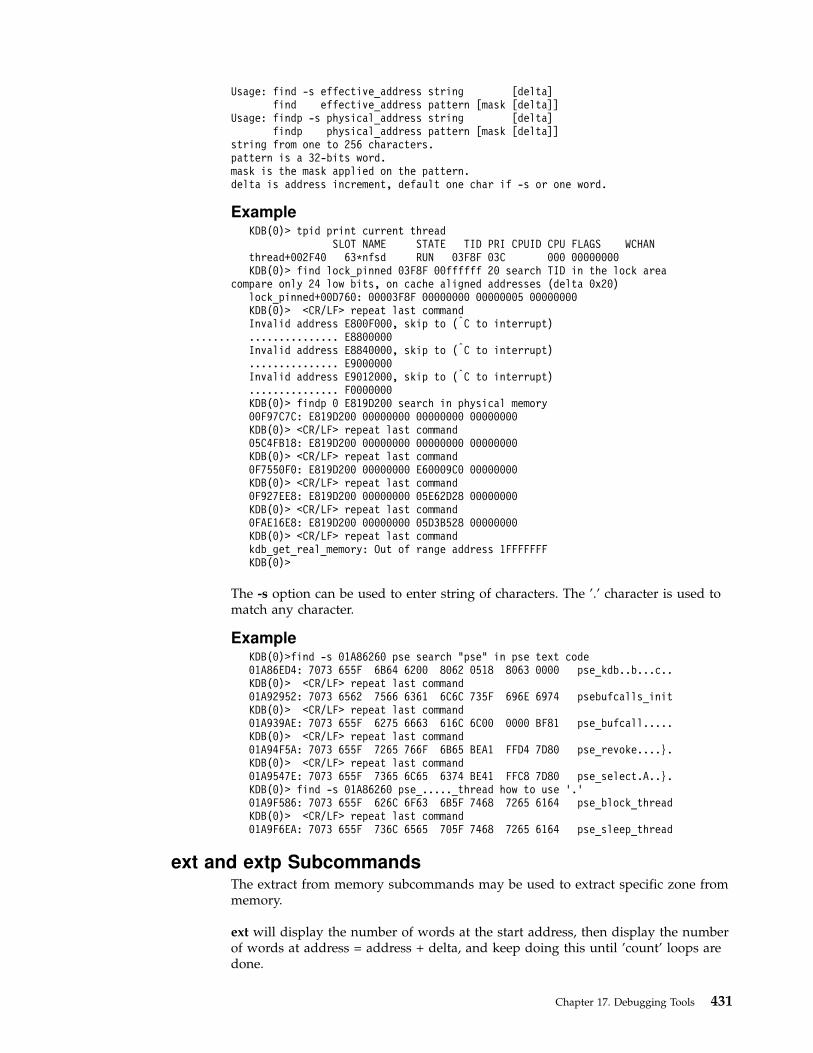
Usage: find -s effective_address string [delta]find effective_address pattern [mask [delta]]
Usage: findp -s physical_address string [delta]findp physical_address pattern [mask [delta]]
string from one to 256 characters.pattern is a 32-bits word.mask is the mask applied on the pattern.delta is address increment, default one char if -s or one word.
ExampleKDB(0)> tpid print current thread
SLOT NAME STATE TID PRI CPUID CPU FLAGS WCHANthread+002F40 63*nfsd RUN 03F8F 03C 000 00000000KDB(0)> find lock_pinned 03F8F 00ffffff 20 search TID in the lock area
compare only 24 low bits, on cache aligned addresses (delta 0x20)lock_pinned+00D760: 00003F8F 00000000 00000005 00000000KDB(0)> <CR/LF> repeat last commandInvalid address E800F000, skip to (|C to interrupt)............... E8800000Invalid address E8840000, skip to (|C to interrupt)............... E9000000Invalid address E9012000, skip to (|C to interrupt)............... F0000000KDB(0)> findp 0 E819D200 search in physical memory00F97C7C: E819D200 00000000 00000000 00000000KDB(0)> <CR/LF> repeat last command05C4FB18: E819D200 00000000 00000000 00000000KDB(0)> <CR/LF> repeat last command0F7550F0: E819D200 00000000 E60009C0 00000000KDB(0)> <CR/LF> repeat last command0F927EE8: E819D200 00000000 05E62D28 00000000KDB(0)> <CR/LF> repeat last command0FAE16E8: E819D200 00000000 05D3B528 00000000KDB(0)> <CR/LF> repeat last commandkdb_get_real_memory: Out of range address 1FFFFFFFKDB(0)>
The -s option can be used to enter string of characters. The ’.’ character is used tomatch any character.
ExampleKDB(0)>find -s 01A86260 pse search "pse" in pse text code01A86ED4: 7073 655F 6B64 6200 8062 0518 8063 0000 pse_kdb..b...c..KDB(0)> <CR/LF> repeat last command01A92952: 7073 6562 7566 6361 6C6C 735F 696E 6974 psebufcalls_initKDB(0)> <CR/LF> repeat last command01A939AE: 7073 655F 6275 6663 616C 6C00 0000 BF81 pse_bufcall.....KDB(0)> <CR/LF> repeat last command01A94F5A: 7073 655F 7265 766F 6B65 BEA1 FFD4 7D80 pse_revoke....}.KDB(0)> <CR/LF> repeat last command01A9547E: 7073 655F 7365 6C65 6374 BE41 FFC8 7D80 pse_select.A..}.KDB(0)> find -s 01A86260 pse_....._thread how to use '.'01A9F586: 7073 655F 626C 6F63 6B5F 7468 7265 6164 pse_block_threadKDB(0)> <CR/LF> repeat last command01A9F6EA: 7073 655F 736C 6565 705F 7468 7265 6164 pse_sleep_thread
ext and extp SubcommandsThe extract from memory subcommands may be used to extract specific zone frommemory.
ext will display the number of words at the start address, then display the numberof words at address = address + delta, and keep doing this until ’count’ loops aredone.
Chapter 17. Debugging Tools 431

extp will display the number of words at the start address, then display thenumber of words at address = *(address + delta), and keep doing this until ’count’loops are done.
Usage: ext effective_address delta [size [count]]ext -p effective_address delta [size [count]]
Usage: extp physical_address delta [size [count]]extp -p physical_address delta [size [count]]
delta is address increment or next address offset.size is how many words to print, default one linecount is how many extractions to do, default one.
Example(0)> ext thread+7c 0000C0 1 20 extract scheduler information from threadsthread+00007C: 00021001 ....thread+00013C: 00024800 ..H.thread+0001FC: 00007F01 ....thread+0002BC: 00017F01 ....thread+00037C: 00027F01 ....thread+00043C: 00037F01 ....thread+0004FC: 00021001 ....thread+0005BC: 00012402 ..$.thread+00067C: 00002502 ..%.thread+00073C: 00002502 ..%.thread+0007FC: 00002502 ..%.thread+0008BC: 00032502 ..%.thread+00097C: 00002502 ..%.thread+000A3C: 00033C00 ..<....KDB(0)> extp 0 4000000 4 100 extract memory using real address00000000: 00000000 00000000 00000000 00000000 ................04000000: 00004001 00000000 00000000 00000000 [email protected]: 00008001 00000000 00000000 00000000 ................0C000000: D0071128 F010EA08 F010EA68 F010F028 ...(.......h...(10000000: 00000000 00000000 00000000 00000000 ................14000000: 746C2E63 2C206C69 62636673 2C20626F tl.c, libcfs, bo18000000: 20005924 0000031D 20001B04 20005924 .Y$.... ... .Y$1C000000: 000C000D 000E000F 00100011 00120013 ................20000000: kdb_get_real_memory: Out of range address 20000000
The -p option specifies that delta is offset of the field giving the next address. Alist can be printed by this way.
Example(0)> ext -p proc+500 14 8 10 print siblings of a processproc+000500: 07000000 00000303 00000000 00000000 ................proc+000510: 00000000 E3000400 E3000500 00000000 ................proc+000400: 07000000 00000303 00000000 00000000 ................proc+000410: 00000000 E3000300 E3000400 00000000 ................proc+000300: 07000000 00000303 00000000 00000000 ................proc+000310: 00000000 E3000200 E3000300 00000000 ................proc+000200: 07000000 00000303 00000000 00000000 ................proc+000210: 00000000 00000000 E3000200 00000000 ................
Modify Memory Subcommands for the KDB Kernel Debugger and kdb
Command
m, mw, md, mp, mpw, and mpd Subcommands
Note: This subcommand is only available within the kdb command; it is notincluded in the KDB Kernel Debugger.
432 Kernel Extensions and Device Support Programming Concepts
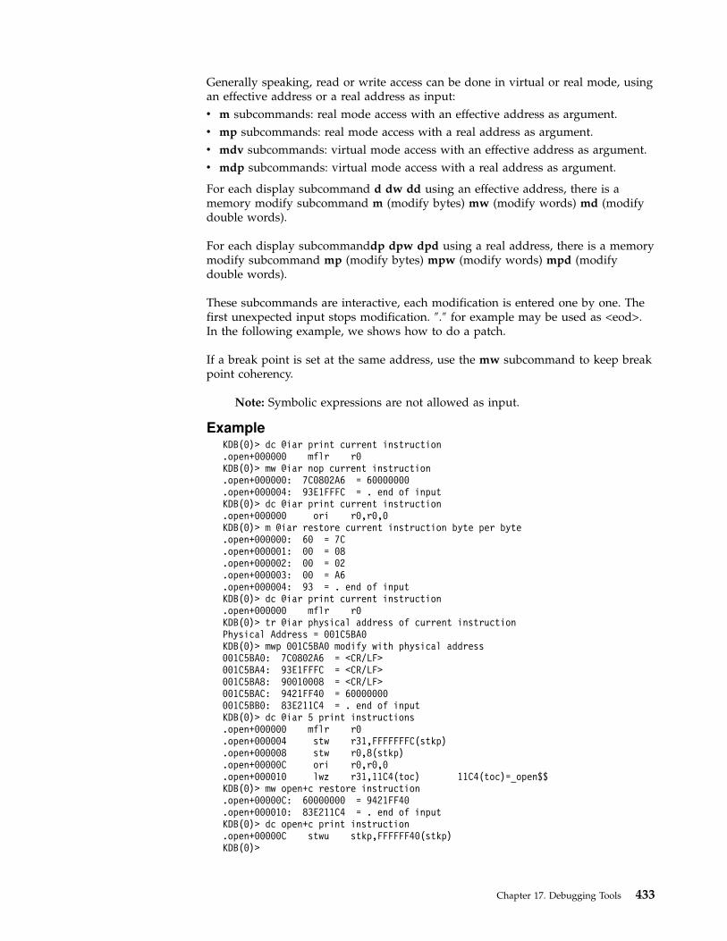
Generally speaking, read or write access can be done in virtual or real mode, usingan effective address or a real address as input:
v m subcommands: real mode access with an effective address as argument.
v mp subcommands: real mode access with a real address as argument.
v mdv subcommands: virtual mode access with an effective address as argument.
v mdp subcommands: virtual mode access with a real address as argument.
For each display subcommand d dw dd using an effective address, there is amemory modify subcommand m (modify bytes) mw (modify words) md (modifydouble words).
For each display subcommanddp dpw dpd using a real address, there is a memorymodify subcommand mp (modify bytes) mpw (modify words) mpd (modifydouble words).
These subcommands are interactive, each modification is entered one by one. Thefirst unexpected input stops modification. ″.″ for example may be used as <eod>.In the following example, we shows how to do a patch.
If a break point is set at the same address, use the mw subcommand to keep breakpoint coherency.
Note: Symbolic expressions are not allowed as input.
ExampleKDB(0)> dc @iar print current instruction.open+000000 mflr r0KDB(0)> mw @iar nop current instruction.open+000000: 7C0802A6 = 60000000.open+000004: 93E1FFFC = . end of inputKDB(0)> dc @iar print current instruction.open+000000 ori r0,r0,0KDB(0)> m @iar restore current instruction byte per byte.open+000000: 60 = 7C.open+000001: 00 = 08.open+000002: 00 = 02.open+000003: 00 = A6.open+000004: 93 = . end of inputKDB(0)> dc @iar print current instruction.open+000000 mflr r0KDB(0)> tr @iar physical address of current instructionPhysical Address = 001C5BA0KDB(0)> mwp 001C5BA0 modify with physical address001C5BA0: 7C0802A6 = <CR/LF>001C5BA4: 93E1FFFC = <CR/LF>001C5BA8: 90010008 = <CR/LF>001C5BAC: 9421FF40 = 60000000001C5BB0: 83E211C4 = . end of inputKDB(0)> dc @iar 5 print instructions.open+000000 mflr r0.open+000004 stw r31,FFFFFFFC(stkp).open+000008 stw r0,8(stkp).open+00000C ori r0,r0,0.open+000010 lwz r31,11C4(toc) 11C4(toc)=_open$$KDB(0)> mw open+c restore instruction.open+00000C: 60000000 = 9421FF40.open+000010: 83E211C4 = . end of inputKDB(0)> dc open+c print instruction.open+00000C stwu stkp,FFFFFF40(stkp)KDB(0)>
Chapter 17. Debugging Tools 433
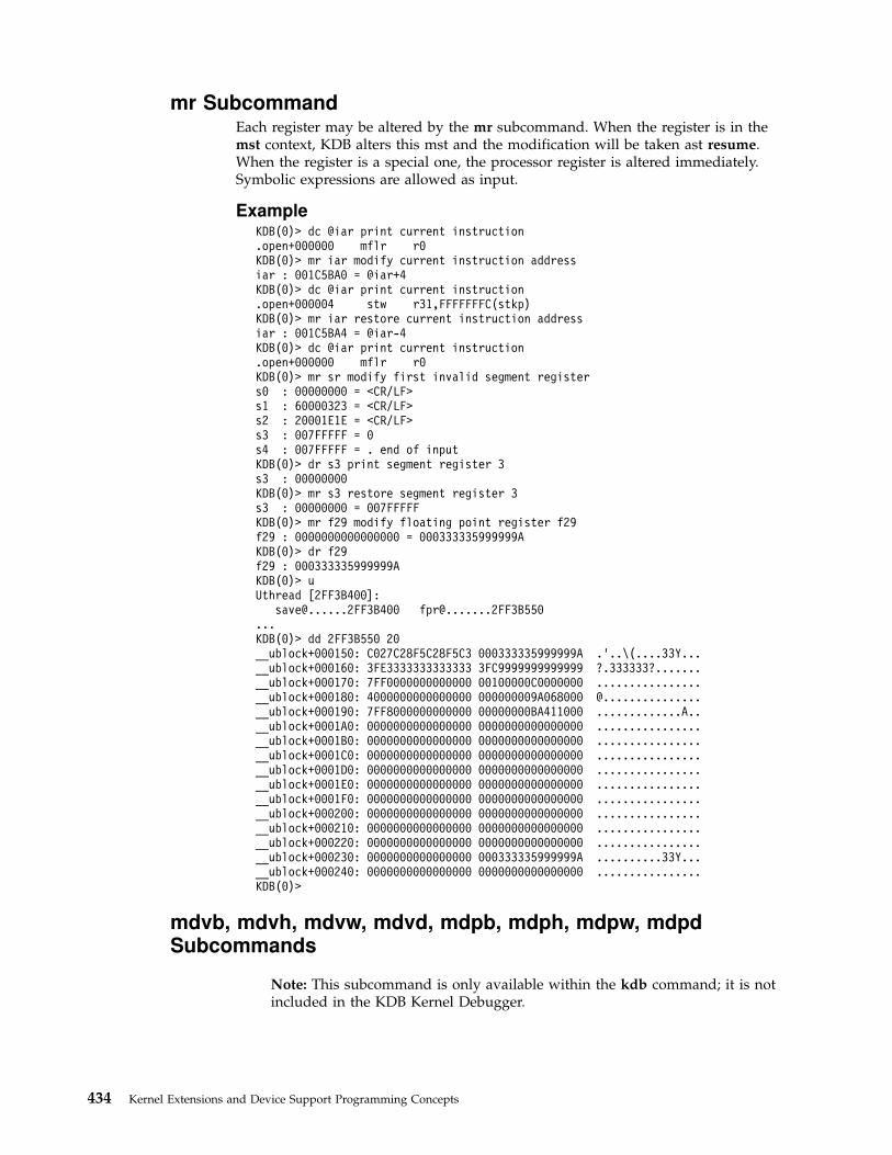
mr SubcommandEach register may be altered by the mr subcommand. When the register is in themst context, KDB alters this mst and the modification will be taken ast resume.When the register is a special one, the processor register is altered immediately.Symbolic expressions are allowed as input.
ExampleKDB(0)> dc @iar print current instruction.open+000000 mflr r0KDB(0)> mr iar modify current instruction addressiar : 001C5BA0 = @iar+4KDB(0)> dc @iar print current instruction.open+000004 stw r31,FFFFFFFC(stkp)KDB(0)> mr iar restore current instruction addressiar : 001C5BA4 = @iar-4KDB(0)> dc @iar print current instruction.open+000000 mflr r0KDB(0)> mr sr modify first invalid segment registers0 : 00000000 = <CR/LF>s1 : 60000323 = <CR/LF>s2 : 20001E1E = <CR/LF>s3 : 007FFFFF = 0s4 : 007FFFFF = . end of inputKDB(0)> dr s3 print segment register 3s3 : 00000000KDB(0)> mr s3 restore segment register 3s3 : 00000000 = 007FFFFFKDB(0)> mr f29 modify floating point register f29f29 : 0000000000000000 = 000333335999999AKDB(0)> dr f29f29 : 000333335999999AKDB(0)> uUthread [2FF3B400]:
[email protected] [email protected](0)> dd 2FF3B550 20__ublock+000150: C027C28F5C28F5C3 000333335999999A .'..\(....33Y...__ublock+000160: 3FE3333333333333 3FC9999999999999 ?.333333?.......__ublock+000170: 7FF0000000000000 00100000C0000000 ................__ublock+000180: 4000000000000000 000000009A068000 @...............__ublock+000190: 7FF8000000000000 00000000BA411000 .............A..__ublock+0001A0: 0000000000000000 0000000000000000 ................__ublock+0001B0: 0000000000000000 0000000000000000 ................__ublock+0001C0: 0000000000000000 0000000000000000 ................__ublock+0001D0: 0000000000000000 0000000000000000 ................__ublock+0001E0: 0000000000000000 0000000000000000 ................__ublock+0001F0: 0000000000000000 0000000000000000 ................__ublock+000200: 0000000000000000 0000000000000000 ................__ublock+000210: 0000000000000000 0000000000000000 ................__ublock+000220: 0000000000000000 0000000000000000 ................__ublock+000230: 0000000000000000 000333335999999A ..........33Y...__ublock+000240: 0000000000000000 0000000000000000 ................KDB(0)>
mdvb, mdvh, mdvw, mdvd, mdpb, mdph, mdpw, mdpdSubcommands
Note: This subcommand is only available within the kdb command; it is notincluded in the KDB Kernel Debugger.
434 Kernel Extensions and Device Support Programming Concepts
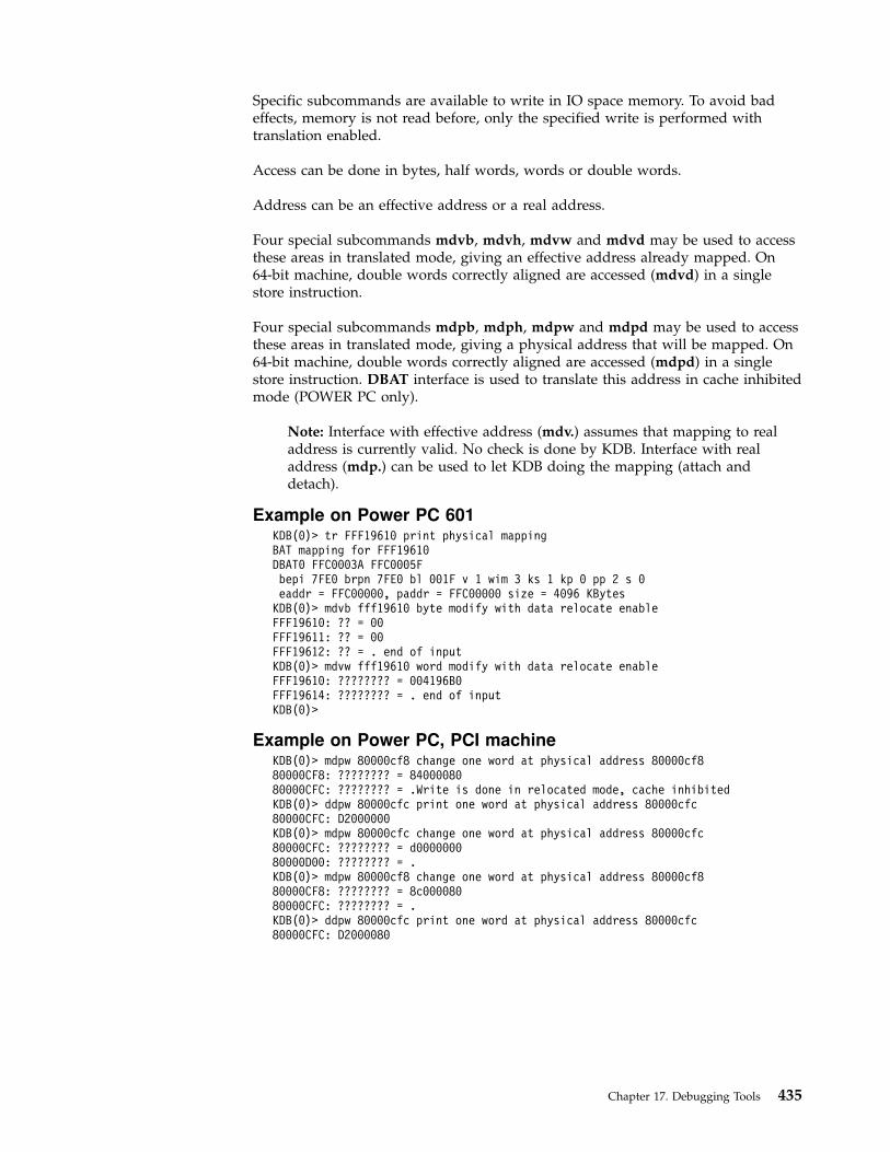
Specific subcommands are available to write in IO space memory. To avoid badeffects, memory is not read before, only the specified write is performed withtranslation enabled.
Access can be done in bytes, half words, words or double words.
Address can be an effective address or a real address.
Four special subcommands mdvb, mdvh, mdvw and mdvd may be used to accessthese areas in translated mode, giving an effective address already mapped. On64-bit machine, double words correctly aligned are accessed (mdvd) in a singlestore instruction.
Four special subcommands mdpb, mdph, mdpw and mdpd may be used to accessthese areas in translated mode, giving a physical address that will be mapped. On64-bit machine, double words correctly aligned are accessed (mdpd) in a singlestore instruction. DBAT interface is used to translate this address in cache inhibitedmode (POWER PC only).
Note: Interface with effective address (mdv.) assumes that mapping to realaddress is currently valid. No check is done by KDB. Interface with realaddress (mdp.) can be used to let KDB doing the mapping (attach anddetach).
Example on Power PC 601KDB(0)> tr FFF19610 print physical mappingBAT mapping for FFF19610DBAT0 FFC0003A FFC0005Fbepi 7FE0 brpn 7FE0 bl 001F v 1 wim 3 ks 1 kp 0 pp 2 s 0eaddr = FFC00000, paddr = FFC00000 size = 4096 KBytes
KDB(0)> mdvb fff19610 byte modify with data relocate enableFFF19610: ?? = 00FFF19611: ?? = 00FFF19612: ?? = . end of inputKDB(0)> mdvw fff19610 word modify with data relocate enableFFF19610: ???????? = 004196B0FFF19614: ???????? = . end of inputKDB(0)>
Example on Power PC, PCI machineKDB(0)> mdpw 80000cf8 change one word at physical address 80000cf880000CF8: ???????? = 8400008080000CFC: ???????? = .Write is done in relocated mode, cache inhibitedKDB(0)> ddpw 80000cfc print one word at physical address 80000cfc80000CFC: D2000000KDB(0)> mdpw 80000cfc change one word at physical address 80000cfc80000CFC: ???????? = d000000080000D00: ???????? = .KDB(0)> mdpw 80000cf8 change one word at physical address 80000cf880000CF8: ???????? = 8c00008080000CFC: ???????? = .KDB(0)> ddpw 80000cfc print one word at physical address 80000cfc80000CFC: D2000080
Chapter 17. Debugging Tools 435

Namelist/Symbol Subcommands for the KDB Kernel Debugger and kdb
Command
nm and ts SubcommandsThe following subcommands may be used to swap from symbol to hexadecimalvalues.
ExampleKDB(0)> nm __ublock print symbol valueSymbol Address : 2FF3B400KDB(0)> ts E3000000 print symbol nameproc+000000
ns SubcommandThe ns toggle may be used to disable symbol printing.
ExampleKDB(0)> set 2 do not print contextmst_wanted is falseKDB(0)> f print stack framethread+00D080 STACK:[000095A4].simple_lock+0000A4 ()[0007F4A0]v_prefreescb+000038 (??, ??)[00017AC4]isync_vcs3+000004 (??, ??)____ Exception (2FF40000) ____[00009414].unlock_enable+000110 ()[00009410].unlock_enable+00010C ()[0000CDD0]as_det+0000A8 (??, ??)[001B33F8]shm_freespace+000080 (??, ??)[001F6A04]rmmapseg+0000D0 (??)[001E41DC]vm_map_entry_delete+00023C (??, ??)[001E4828]vm_map_delete+000158 (??, ??, ??)[001E5034]vm_map_remove+000064 (??, ??, ??)[001E6514]munmap+0000C0 (??, ??)[000036FC].sys_call+000000 ()KDB(0)> ns enable no symbol printingSymbolic name translation offKDB(0)> f print stack frameE600D080 STACK:000095A4 ()0007F4A0 (??, ??)00017AC4 (??, ??)____ Exception (2FF40000) ____00009414 ()00009410 ()0000CDD0 (??, ??)001B33F8 (??, ??)001F6A04 (??)001E41DC (??, ??)001E4828 (??, ??, ??)001E5034 (??, ??, ??)001E6514 (??, ??)000036FC ()KDB(0)> ns disable no symbol printingSymbolic name translation onKDB(0)>
436 Kernel Extensions and Device Support Programming Concepts

Watch Break Points Subcommands for the KDB Kernel Debugger and
kdb Command
wr, ww, wrw, cw, lwr, lww, lwrw, and lcw Subcommands
Note: This subcommand is only available within the kdb command; it is notincluded in the KDB Kernel Debugger.
On POWER PC architecture, a watch register may be used (called DABR DataAddress Breakpoint Register or HID5 on POWER 601) to enter KDB when aspecified effective address is accessed. The register holds a double-word effectiveaddress and bits to specify load and/or store operation. See PowerPCImplementation Definition for the 601-604-620 Processor (book IV) to have moreinformation. The wr subcommand may be used to stop on load instruction. Theww subcommand may be used to stop on store instruction. The wrw subcommandmay be used to stop on load or store instruction. Without argument, thesubcommand prints the current active watch subcommand. The cw subcommandmay be used to clear the last watch subcommand. This subcommand is global toall processors, each processor may have different watch address with the localsubcommands lwr lww lwrw lcw. When no size is specified, the default size is 8bytes and the address is double word aligned. Otherwise KDB checks the faultingaddress with the specified range and continues execution if it does not match.
It is possible to specify if the address is physical or virtual with -p or -v option.604 and 620 processors take care of the translation mode, and it is necessary tospecify which mode is used. By default KDB chooses the current state of themachine: if the subcommand is entered beforeVMM inititialisation, the watchaddress is physical (real address), else virtual (effective address).
ExampleKDB(0)> ww -p emulate_count set a data break point (physical address, write mode)KDB(0)> ww print current data break pointsCPU 0: emulate_count+000000 paddr=00238360 size=8 hit=0 mode=WCPU 1: emulate_count+000000 paddr=00238360 size=8 hit=0 mode=WKDB(0)> e exit the debugger...Watch trap: 00238360 <emulate_count+000000>power_asm_emulate+00013C stw r28,0(r30)
r28=0000003A,0(r30)=emulate_countKDB(0)> ww print current data break pointsCPU 0: emulate_count+000000 paddr=00238360 size=8 hit=1 mode=WCPU 1: emulate_count+000000 paddr=00238360 size=8 hit=0 mode=WKDB(0)> wr sysinfo set a data break point (read mode)KDB(0)> wr print current data break pointsCPU 0: sysinfo+000000 eaddr=003BA9D0 vsid=00000000 size=8 hit=0 mode=RCPU 1: sysinfo+000000 eaddr=003BA9D0 vsid=00000000 size=8 hit=0 mode=RKDB(0)> e exit the debugger...Watch trap: 003BA9D4 <sysinfo+000004>.fetch_and_add+000008 lwarx r3,0,r6
r3=sysinfo+000004,r6=sysinfo+000004KDB(0)> cw clear data break points
Chapter 17. Debugging Tools 437
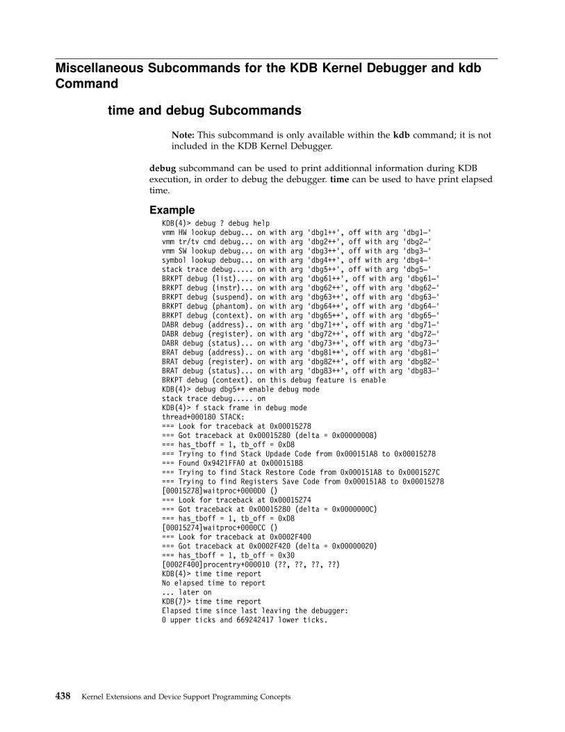
Miscellaneous Subcommands for the KDB Kernel Debugger and kdb
Command
time and debug Subcommands
Note: This subcommand is only available within the kdb command; it is notincluded in the KDB Kernel Debugger.
debug subcommand can be used to print additionnal information during KDBexecution, in order to debug the debugger. time can be used to have print elapsedtime.
ExampleKDB(4)> debug ? debug helpvmm HW lookup debug... on with arg 'dbg1++', off with arg 'dbg1—'vmm tr/tv cmd debug... on with arg 'dbg2++', off with arg 'dbg2—'vmm SW lookup debug... on with arg 'dbg3++', off with arg 'dbg3—'symbol lookup debug... on with arg 'dbg4++', off with arg 'dbg4—'stack trace debug..... on with arg 'dbg5++', off with arg 'dbg5—'BRKPT debug (list).... on with arg 'dbg61++', off with arg 'dbg61—'BRKPT debug (instr)... on with arg 'dbg62++', off with arg 'dbg62—'BRKPT debug (suspend). on with arg 'dbg63++', off with arg 'dbg63—'BRKPT debug (phantom). on with arg 'dbg64++', off with arg 'dbg64—'BRKPT debug (context). on with arg 'dbg65++', off with arg 'dbg65—'DABR debug (address).. on with arg 'dbg71++', off with arg 'dbg71—'DABR debug (register). on with arg 'dbg72++', off with arg 'dbg72—'DABR debug (status)... on with arg 'dbg73++', off with arg 'dbg73—'BRAT debug (address).. on with arg 'dbg81++', off with arg 'dbg81—'BRAT debug (register). on with arg 'dbg82++', off with arg 'dbg82—'BRAT debug (status)... on with arg 'dbg83++', off with arg 'dbg83—'BRKPT debug (context). on this debug feature is enableKDB(4)> debug dbg5++ enable debug modestack trace debug..... onKDB(4)> f stack frame in debug modethread+000180 STACK:=== Look for traceback at 0x00015278=== Got traceback at 0x00015280 (delta = 0x00000008)=== has_tboff = 1, tb_off = 0xD8=== Trying to find Stack Updade Code from 0x000151A8 to 0x00015278=== Found 0x9421FFA0 at 0x000151B8=== Trying to find Stack Restore Code from 0x000151A8 to 0x0001527C=== Trying to find Registers Save Code from 0x000151A8 to 0x00015278[00015278]waitproc+0000D0 ()=== Look for traceback at 0x00015274=== Got traceback at 0x00015280 (delta = 0x0000000C)=== has_tboff = 1, tb_off = 0xD8[00015274]waitproc+0000CC ()=== Look for traceback at 0x0002F400=== Got traceback at 0x0002F420 (delta = 0x00000020)=== has_tboff = 1, tb_off = 0x30[0002F400]procentry+000010 (??, ??, ??, ??)KDB(4)> time time reportNo elapsed time to report... later onKDB(7)> time time reportElapsed time since last leaving the debugger:0 upper ticks and 669242417 lower ticks.
438 Kernel Extensions and Device Support Programming Concepts
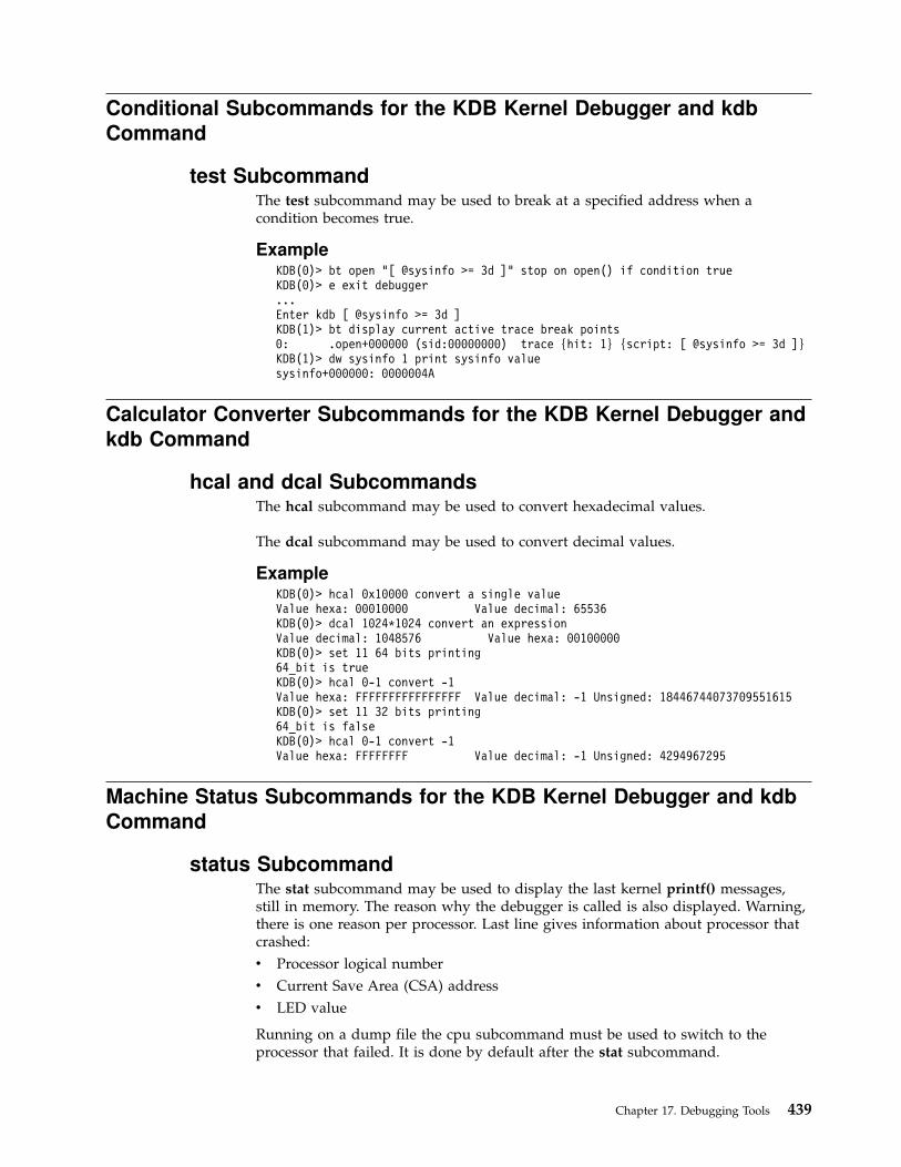
Conditional Subcommands for the KDB Kernel Debugger and kdb
Command
test SubcommandThe test subcommand may be used to break at a specified address when acondition becomes true.
ExampleKDB(0)> bt open "[ @sysinfo >= 3d ]" stop on open() if condition trueKDB(0)> e exit debugger...Enter kdb [ @sysinfo >= 3d ]KDB(1)> bt display current active trace break points0: .open+000000 (sid:00000000) trace {hit: 1} {script: [ @sysinfo >= 3d ]}KDB(1)> dw sysinfo 1 print sysinfo valuesysinfo+000000: 0000004A
Calculator Converter Subcommands for the KDB Kernel Debugger and
kdb Command
hcal and dcal SubcommandsThe hcal subcommand may be used to convert hexadecimal values.
The dcal subcommand may be used to convert decimal values.
ExampleKDB(0)> hcal 0x10000 convert a single valueValue hexa: 00010000 Value decimal: 65536KDB(0)> dcal 1024*1024 convert an expressionValue decimal: 1048576 Value hexa: 00100000KDB(0)> set 11 64 bits printing64_bit is trueKDB(0)> hcal 0-1 convert -1Value hexa: FFFFFFFFFFFFFFFF Value decimal: -1 Unsigned: 18446744073709551615KDB(0)> set 11 32 bits printing64_bit is falseKDB(0)> hcal 0-1 convert -1Value hexa: FFFFFFFF Value decimal: -1 Unsigned: 4294967295
Machine Status Subcommands for the KDB Kernel Debugger and kdb
Command
status SubcommandThe stat subcommand may be used to display the last kernel printf() messages,still in memory. The reason why the debugger is called is also displayed. Warning,there is one reason per processor. Last line gives information about processor thatcrashed:
v Processor logical number
v Current Save Area (CSA) address
v LED value
Running on a dump file the cpu subcommand must be used to switch to theprocessor that failed. It is done by default after the stat subcommand.
Chapter 17. Debugging Tools 439
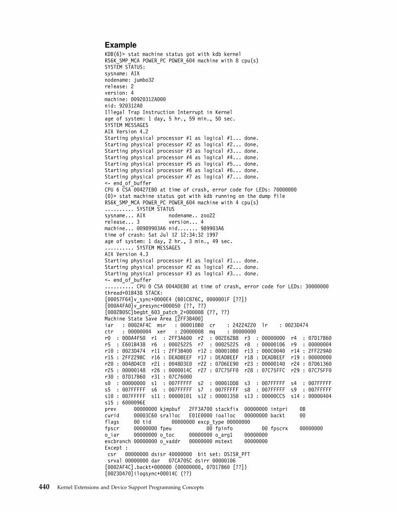
ExampleKDB(6)> stat machine status got with kdb kernelRS6K_SMP_MCA POWER_PC POWER_604 machine with 8 cpu(s)SYSTEM STATUS:sysname: AIXnodename: jumbo32release: 2version: 4machine: 00920312A000nid: 920312A0Illegal Trap Instruction Interrupt in Kernelage of system: 1 day, 5 hr., 59 min., 50 sec.SYSTEM MESSAGESAIX Version 4.2Starting physical processor #1 as logical #1... done.Starting physical processor #2 as logical #2... done.Starting physical processor #3 as logical #3... done.Starting physical processor #4 as logical #4... done.Starting physical processor #5 as logical #5... done.Starting physical processor #6 as logical #6... done.Starting physical processor #7 as logical #7... done.<- end_of_bufferCPU 6 CSA 00427EB0 at time of crash, error code for LEDs: 70000000(0)> stat machine status got with kdb running on the dump fileRS6K_SMP_MCA POWER_PC POWER_604 machine with 4 cpu(s).......... SYSTEM STATUSsysname... AIX nodename.. zoo22release... 3 version... 4machine... 00989903A6 nid....... 989903A6time of crash: Sat Jul 12 12:34:32 1997age of system: 1 day, 2 hr., 3 min., 49 sec........... SYSTEM MESSAGESAIX Version 4.3Starting physical processor #1 as logical #1... done.Starting physical processor #2 as logical #2... done.Starting physical processor #3 as logical #3... done.<- end_of_buffer.......... CPU 0 CSA 004ADEB0 at time of crash, error code for LEDs: 30000000thread+01B438 STACK:[00057F64]v_sync+0000E4 (B01C876C, 0000001F [??])[000A4FA0]v_presync+000050 (??, ??)[0002B05C]begbt_603_patch_2+000008 (??, ??)Machine State Save Area [2FF3B400]iar : 0002AF4C msr : 000010B0 cr : 24224220 lr : 0023D474ctr : 00000004 xer : 20000008 mq : 00000000r0 : 000A4F50 r1 : 2FF3A600 r2 : 002E62B8 r3 : 00000000 r4 : 07D17B60r5 : E601B438 r6 : 00025225 r7 : 00025225 r8 : 00000106 r9 : 00000004r10 : 0023D474 r11 : 2FF3B400 r12 : 000010B0 r13 : 000C0040 r14 : 2FF229A0r15 : 2FF229BC r16 : DEADBEEF r17 : DEADBEEF r18 : DEADBEEF r19 : 00000000r20 : 0048D4C0 r21 : 0048D3E0 r22 : 07D6EE90 r23 : 00000140 r24 : 07D61360r25 : 00000148 r26 : 0000014C r27 : 07C75FF0 r28 : 07C75FFC r29 : 07C75FF0r30 : 07D17B60 r31 : 07C76000s0 : 00000000 s1 : 007FFFFF s2 : 00001DD8 s3 : 007FFFFF s4 : 007FFFFFs5 : 007FFFFF s6 : 007FFFFF s7 : 007FFFFF s8 : 007FFFFF s9 : 007FFFFFs10 : 007FFFFF s11 : 00000101 s12 : 0000135B s13 : 00000CC5 s14 : 00000404s15 : 6000096Eprev 00000000 kjmpbuf 2FF3A700 stackfix 00000000 intpri 0Bcurid 00003C60 sralloc E01E0000 ioalloc 00000000 backt 00flags 00 tid 00000000 excp_type 00000000fpscr 00000000 fpeu 00 fpinfo 00 fpscrx 00000000o_iar 00000000 o_toc 00000000 o_arg1 00000000excbranch 00000000 o_vaddr 00000000 mstext 00000000Except :csr 00000000 dsisr 40000000 bit set: DSISR_PFTsrval 00000000 dar 07CA705C dsirr 00000106[0002AF4C].backt+000000 (00000000, 07D17B60 [??])[0023D470]ilogsync+00014C (??)
440 Kernel Extensions and Device Support Programming Concepts

[002894B8]logsync+000090 (??)[0028899C]logmvc+000124 (??, ??, ??, ??)[0023AB68]logafter+000100 (??, ??, ??)[0023A46C]commit2+0001EC (??)[0023BF50]finicom+0000BC (??, ??)[0023C2CC]comlist+0001F0 (??, ??)[0029391C]jfs_rename+000794 (??, ??, ??, ??, ??, ??, ??)[00248220]vnop_rename+000038 (??, ??, ??, ??, ??, ??, ??)[0026A168]rename+000380 (??, ??)(0)>
switch SubcommandThe switch subcommand is very usefull. By default, KDB shows the currentprocess virtual space. But it is possible to elect another process, and to have all itsvirtual space on line. When KDB is exiting, the initial context is automaticallyrestored. If local break points are process/thread attached, the switched context istaken as break point context. As kernel address space and user address space arenot identical, the switch subcommand can be used to switch between user (sw u)and kernel (sw k) space.
ExampleKDB(0)> sw 12 switch to thread slot 12Switch to thread: <thread+000900>KDB(0)> f print stack tracethread+000900 STACK:[000215FC]e_block_thread+000250 ()[00021C48]e_sleep_thread+000070 (??, ??, ??)[000200F4]errread+00009C (??, ??)[001C89B4]rdevread+000120 (??, ??, ??, ??)[0023A61C]cdev_rdwr+00009C (??, ??, ??, ??, ??, ??, ??)[00216324]spec_rdwr+00008C (??, ??, ??, ??, ??, ??, ??, ??)[001CEA3C]vnop_rdwr+000070 (??, ??, ??, ??, ??, ??, ??, ??)[001BDB0C]rwuio+0000CC (??, ??, ??, ??, ??, ??, ??, ??)[001BDF40]rdwr+000184 (??, ??, ??, ??, ??, ??)[001BDD68]kreadv+000064 (??, ??, ??, ??)[000037D8].sys_call+000000 ()[D0046B68]read+000028 (??, ??, ??)[1000167C]child+000120 ()[10001A84]main+0000E4 (??, ??)[1000014C].__start+00004C ()KDB(0)> dr sr display segment registerss0 : 00000000 s1 : 007FFFFF s2 : 00000AB7 s3 : 007FFFFF s4 : 007FFFFFs5 : 007FFFFF s6 : 007FFFFF s7 : 007FFFFF s8 : 007FFFFF s9 : 007FFFFFs10 : 007FFFFF s11 : 007FFFFF s12 : 007FFFFF s13 : 6000058B s14 : 00000204s15 : 60000CBBKDB(0)> sw u switch to user contextKDB(0)> dr sr display segment registerss0 : 60000000 s1 : 600009B1 s2 : 60000AB7 s3 : 007FFFFF s4 : 007FFFFFs5 : 007FFFFF s6 : 007FFFFF s7 : 007FFFFF s8 : 007FFFFF s9 : 007FFFFFs10 : 007FFFFF s11 : 007FFFFF s12 : 007FFFFF s13 : 6000058B s14 : 007FFFFFs15 : 60000CBBNow it is possible to look at user codeFor example, find how read() is called by child()KDB(0)> dc 1000167C print child() code (seg 1 is now valid)1000167C bl <1000A1BC>KDB(0)> dc 1000A1BC 6 print child() code1000A1BC lwz r12,244(toc)1000A1C0 stw toc,14(stkp)1000A1C4 lwz r0,0(r12)1000A1C8 lwz toc,4(r12)1000A1CC mtctr r01000A1D0 bcctr... find stack pointer of child() routine with 'set 9; f'[D0046B68]read+000028 (??, ??, ??)
Chapter 17. Debugging Tools 441
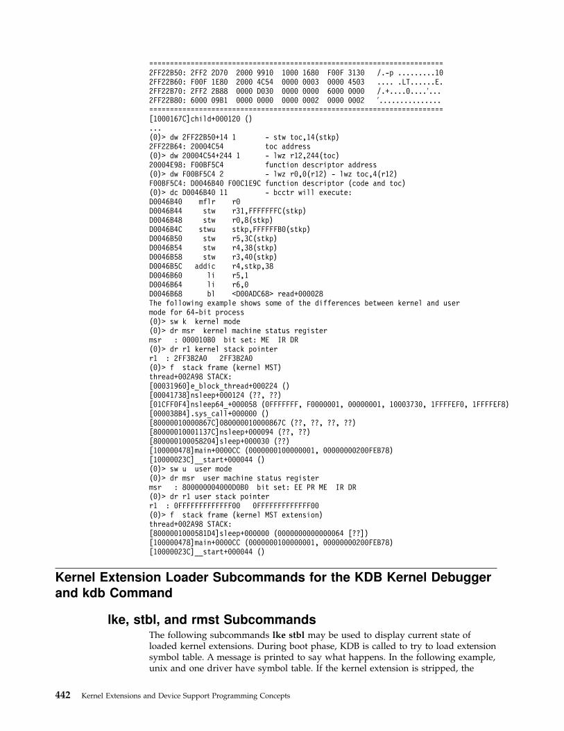
=======================================================================2FF22B50: 2FF2 2D70 2000 9910 1000 1680 F00F 3130 /.-p .........102FF22B60: F00F 1E80 2000 4C54 0000 0003 0000 4503 .... .LT......E.2FF22B70: 2FF2 2B88 0000 D030 0000 0000 6000 0000 /.+....0....′...2FF22B80: 6000 09B1 0000 0000 0000 0002 0000 0002 ′...............=======================================================================[1000167C]child+000120 ()...(0)> dw 2FF22B50+14 1 - stw toc,14(stkp)2FF22B64: 20004C54 toc address(0)> dw 20004C54+244 1 - lwz r12,244(toc)20004E98: F00BF5C4 function descriptor address(0)> dw F00BF5C4 2 - lwz r0,0(r12) - lwz toc,4(r12)F00BF5C4: D0046B40 F00C1E9C function descriptor (code and toc)(0)> dc D0046B40 11 - bcctr will execute:D0046B40 mflr r0D0046B44 stw r31,FFFFFFFC(stkp)D0046B48 stw r0,8(stkp)D0046B4C stwu stkp,FFFFFFB0(stkp)D0046B50 stw r5,3C(stkp)D0046B54 stw r4,38(stkp)D0046B58 stw r3,40(stkp)D0046B5C addic r4,stkp,38D0046B60 li r5,1D0046B64 li r6,0D0046B68 bl <D00ADC68> read+000028The following example shows some of the differences between kernel and usermode for 64-bit process(0)> sw k kernel mode(0)> dr msr kernel machine status registermsr : 000010B0 bit set: ME IR DR(0)> dr r1 kernel stack pointerr1 : 2FF3B2A0 2FF3B2A0(0)> f stack frame (kernel MST)thread+002A98 STACK:[00031960]e_block_thread+000224 ()[00041738]nsleep+000124 (??, ??)[01CFF0F4]nsleep64_+000058 (0FFFFFFF, F0000001, 00000001, 10003730, 1FFFFEF0, 1FFFFEF8)[000038B4].sys_call+000000 ()[80000010000867C]080000010000867C (??, ??, ??, ??)[80000010001137C]nsleep+000094 (??, ??)[800000100058204]sleep+000030 (??)[100000478]main+0000CC (0000000100000001, 00000000200FEB78)[10000023C]__start+000044 ()(0)> sw u user mode(0)> dr msr user machine status registermsr : 800000004000D0B0 bit set: EE PR ME IR DR(0)> dr r1 user stack pointerr1 : 0FFFFFFFFFFFFF00 0FFFFFFFFFFFFF00(0)> f stack frame (kernel MST extension)thread+002A98 STACK:[8000001000581D4]sleep+000000 (0000000000000064 [??])[100000478]main+0000CC (0000000100000001, 00000000200FEB78)[10000023C]__start+000044 ()
Kernel Extension Loader Subcommands for the KDB Kernel Debugger
and kdb Command
lke, stbl, and rmst SubcommandsThe following subcommands lke stbl may be used to display current state ofloaded kernel extensions. During boot phase, KDB is called to try to load extensionsymbol table. A message is printed to say what happens. In the following example,unix and one driver have symbol table. If the kernel extension is stripped, the
442 Kernel Extensions and Device Support Programming Concepts

symbol table is not loaded in memory, but it is possible to build a new symboltable with the traceback table. The lke subcommand can be used for this purpose.A symbol name cache is managed inside KDB, and the cache is filled with functionnames with lke entry subcommand. This cache is a circular buffer, old entries willbe removed by new ones when the cache is full.
v lke <slot|address> populate the cache with loader entry as argument
v lke -a <address> populate the cache with kernext address as argument
v lke -l list current cached name list
v stbl list all symbol tables connected to KDB
v rmst disconnect a specified symbol table
Example... during boot phaseno symbol [/etc/drivers/mddtu_load]no symbol [/etc/drivers/fd]Preserving 14280 bytes of symbol table [/etc/drivers/rsdd]no symbol [/etc/drivers/posixdd]no symbol [/etc/drivers/dtropendd]...KDB(4)> stbl list symbol table entries
LDRENTRY TEXT DATA TOC MODULE NAME1 00000000 00000000 00000000 00207EF0 /unix2 0B04C400 0156F0F0 015784F0 01578840 /etc/drivers/rsdd
KDB(4)> rmst 2 ignore second entryKDB(4)> stbl list symbol table entries
LDRENTRY TEXT DATA TOC MODULE NAME1 00000000 00000000 00000000 00207EF0 /unix
KDB(4)> stbl 1 list a symbol table entryLDRENTRY TEXT DATA TOC MODULE NAME
1 00000000 00000000 00000000 00207EF0 /unixst_desc addr.... 00153920symoff.......... 002A9EB8nb_sym.......... 0000551E...
(0)> lke ? helpA KERNEXT FUNCTION NAME CACHE existswith 1024 entries max (circular buffer)Usage: lke <entry> to populate the cacheUsage: lke -a <address> to populate the cacheUsage: lke -l to list the cache(0)> lke list loaded kernel extensions
ADDRESS FILE FILESIZE FLAGS MODULE NAME1 055ADD00 014620C0 000076CC 00000262 /usr/lib/drivers/pse/psekdb2 055AD780 05704000 000702D0 00000272 /usr/lib/drivers/nfs.ext3 055AD880 05781000 00000D74 00000248 /unix4 055AD380 01461D58 00000348 00000272 /usr/lib/drivers/nfs_kdes.ext5 055AD800 056F7000 00000D20 00000248 /unix6 055AD600 01455140 0000CC0C 00000262 /etc/drivers/ptydd7 055AD500 01451400 00003D2C 00000272 /usr/lib/drivers/if_en8 055AD580 05656000 00000D20 00000248 /unix9 055AD400 055FB000 0004E038 00000272 /usr/lib/drivers/netinet
...39 05518200 0135FA60 00006EFC 00000262 /etc/drivers/bscsidd40 05518300 0135F5B8 0000049C 00000272 /etc/drivers/lsadd41 05518180 04F7D000 00000CCC 00000248 /unix42 05518280 0135E020 00001590 00000262 /etc/drivers/mca_ppc_busdd43 04F61100 00326BF8 00000000 00000256 /unix44 04F61158 04F62000 00000CCC 00000248 /unix(0)> lke 40 print slot 40 and process traceback table
ADDRESS FILE FILESIZE FLAGS MODULE NAME40 05518300 0135F5B8 0000049C 00000272 /etc/drivers/lsaddle_flags....... TEXT KERNELEX DATAINTEXT DATA DATAEXISTSle_next........ 05518180 le_fp.......... 00000000
Chapter 17. Debugging Tools 443
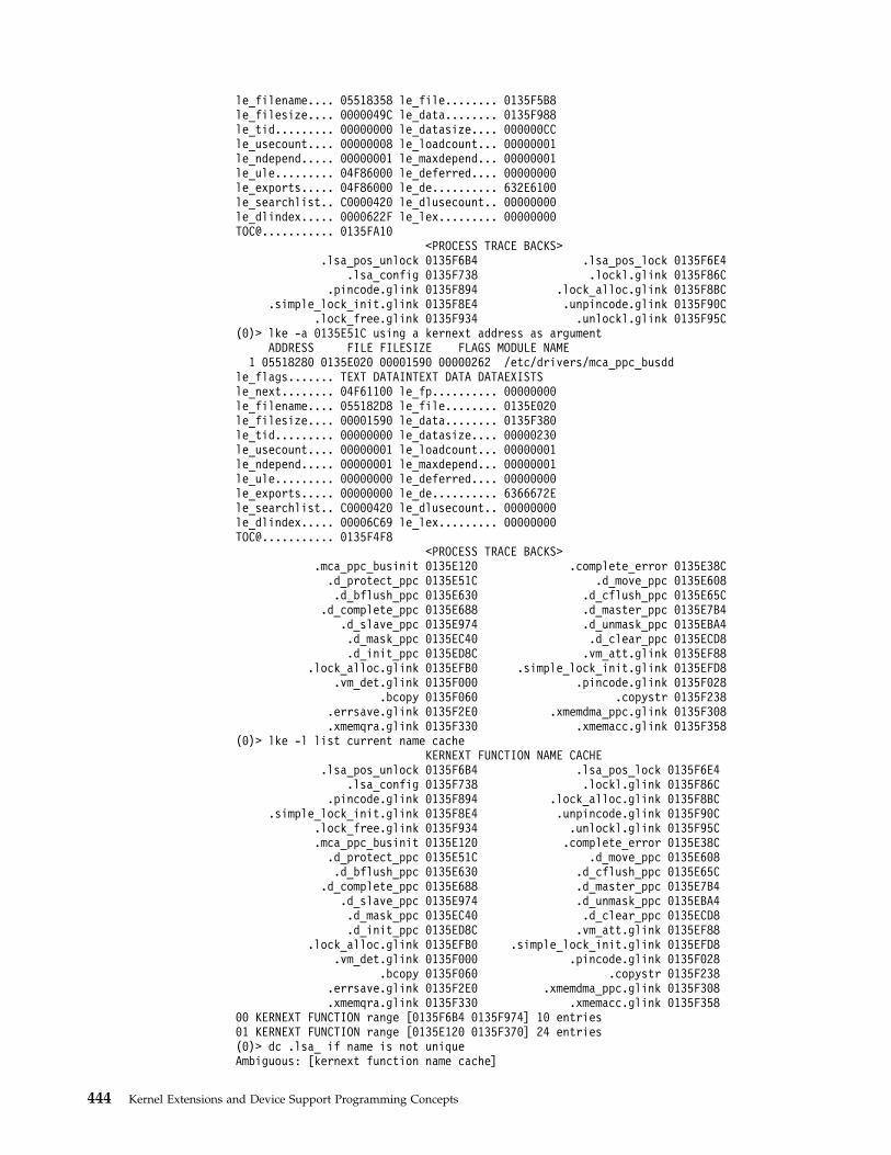
le_filename.... 05518358 le_file........ 0135F5B8le_filesize.... 0000049C le_data........ 0135F988le_tid......... 00000000 le_datasize.... 000000CCle_usecount.... 00000008 le_loadcount... 00000001le_ndepend..... 00000001 le_maxdepend... 00000001le_ule......... 04F86000 le_deferred.... 00000000le_exports..... 04F86000 le_de.......... 632E6100le_searchlist.. C0000420 le_dlusecount.. 00000000le_dlindex..... 0000622F le_lex......... 00000000TOC@........... 0135FA10
<PROCESS TRACE BACKS>.lsa_pos_unlock 0135F6B4 .lsa_pos_lock 0135F6E4
.lsa_config 0135F738 .lockl.glink 0135F86C.pincode.glink 0135F894 .lock_alloc.glink 0135F8BC
.simple_lock_init.glink 0135F8E4 .unpincode.glink 0135F90C.lock_free.glink 0135F934 .unlockl.glink 0135F95C
(0)> lke -a 0135E51C using a kernext address as argumentADDRESS FILE FILESIZE FLAGS MODULE NAME
1 05518280 0135E020 00001590 00000262 /etc/drivers/mca_ppc_busddle_flags....... TEXT DATAINTEXT DATA DATAEXISTSle_next........ 04F61100 le_fp.......... 00000000le_filename.... 055182D8 le_file........ 0135E020le_filesize.... 00001590 le_data........ 0135F380le_tid......... 00000000 le_datasize.... 00000230le_usecount.... 00000001 le_loadcount... 00000001le_ndepend..... 00000001 le_maxdepend... 00000001le_ule......... 00000000 le_deferred.... 00000000le_exports..... 00000000 le_de.......... 6366672Ele_searchlist.. C0000420 le_dlusecount.. 00000000le_dlindex..... 00006C69 le_lex......... 00000000TOC@........... 0135F4F8
<PROCESS TRACE BACKS>.mca_ppc_businit 0135E120 .complete_error 0135E38C
.d_protect_ppc 0135E51C .d_move_ppc 0135E608.d_bflush_ppc 0135E630 .d_cflush_ppc 0135E65C
.d_complete_ppc 0135E688 .d_master_ppc 0135E7B4.d_slave_ppc 0135E974 .d_unmask_ppc 0135EBA4.d_mask_ppc 0135EC40 .d_clear_ppc 0135ECD8.d_init_ppc 0135ED8C .vm_att.glink 0135EF88
.lock_alloc.glink 0135EFB0 .simple_lock_init.glink 0135EFD8.vm_det.glink 0135F000 .pincode.glink 0135F028
.bcopy 0135F060 .copystr 0135F238.errsave.glink 0135F2E0 .xmemdma_ppc.glink 0135F308.xmemqra.glink 0135F330 .xmemacc.glink 0135F358
(0)> lke -l list current name cacheKERNEXT FUNCTION NAME CACHE
.lsa_pos_unlock 0135F6B4 .lsa_pos_lock 0135F6E4.lsa_config 0135F738 .lockl.glink 0135F86C
.pincode.glink 0135F894 .lock_alloc.glink 0135F8BC.simple_lock_init.glink 0135F8E4 .unpincode.glink 0135F90C
.lock_free.glink 0135F934 .unlockl.glink 0135F95C
.mca_ppc_businit 0135E120 .complete_error 0135E38C.d_protect_ppc 0135E51C .d_move_ppc 0135E608.d_bflush_ppc 0135E630 .d_cflush_ppc 0135E65C
.d_complete_ppc 0135E688 .d_master_ppc 0135E7B4.d_slave_ppc 0135E974 .d_unmask_ppc 0135EBA4.d_mask_ppc 0135EC40 .d_clear_ppc 0135ECD8.d_init_ppc 0135ED8C .vm_att.glink 0135EF88
.lock_alloc.glink 0135EFB0 .simple_lock_init.glink 0135EFD8.vm_det.glink 0135F000 .pincode.glink 0135F028
.bcopy 0135F060 .copystr 0135F238.errsave.glink 0135F2E0 .xmemdma_ppc.glink 0135F308.xmemqra.glink 0135F330 .xmemacc.glink 0135F358
00 KERNEXT FUNCTION range [0135F6B4 0135F974] 10 entries01 KERNEXT FUNCTION range [0135E120 0135F370] 24 entries(0)> dc .lsa_ if name is not uniqueAmbiguous: [kernext function name cache]
444 Kernel Extensions and Device Support Programming Concepts

0135F6B4 .lsa_pos_unlock0135F6E4 .lsa_pos_lock0135F738 .lsa_config(0)> expected symbol or address(0)> dc .lsa_config 11 display code.lsa_config+000000 stmw r29,FFFFFFF4(stkp).lsa_config+000004 mflr r0.lsa_config+000008 ori r31,r3,0.lsa_config+00000C stw r0,8(stkp).lsa_config+000010 stwu stkp,FFFFFFB0(stkp).lsa_config+000014 li r30,0.lsa_config+000018 lwz r3,C(toc).lsa_config+00001C li r4,0.lsa_config+000020 bl <.lockl.glink>.lsa_config+000024 lwz toc,14(stkp).lsa_config+000028 lwz r29,14(toc)(0)> dc .lockl.glink 6 display glink code.lockl.glink+000000 lwz r12,10(toc).lockl.glink+000004 stw toc,14(stkp).lockl.glink+000008 lwz r0,0(r12).lockl.glink+00000C lwz toc,4(r12).lockl.glink+000010 mtctr r0.lockl.glink+000014 bcctr
export table SubcommandThe exp subcommand may be used to look for an exported symbol address, or todisplay the export list. By default all the export list is printed, but it is possible tospecify a string as prefix. Notice that export tables can be paged out.
ExampleKDB(0)> exp list export table000814D4 pio_assist019A7708 puthere0007BE90 vmminfo00081FD4 socket01A28A50 tcp_input01A28BFC in_pcb_hash_del019A78E8 adjmsg0000BAB8 execexit00325138 loif01980874 lvm_kp_tid000816E4 ns_detach019A7930 mps_wakeup01A28C50 ip_forward00081E60 ksettickd000810AC uiomove000811EC blkflush0018D97C setpriv01A5CD38 clntkudp_init000820D0 soqremque00178824 devtosth00081984 rtinithead01A5CD8C xdr_rmtcall_args(0)> more (|C to quit) ? |C interruptKDB(0)> exp send search in export table00081F5C sendmsg00081F80 sendto00081F74 sendKDB(0)>
Chapter 17. Debugging Tools 445

Address Translation Subcommands for the KDB Kernel Debugger and
kdb Command
tr and tv SubcommandsThe tr and tv subcommands may be used to decode the MMU translation. tr is ashort format, tv gives all information.
The following example applies on POWER PC achitecture, see POWER PCOperating Environment Architecture book III to have more information.
On tv subcommand, all double hashed entries are dumped, when the entrymatches the specified effective address, corresponding physical address andprotections are displayed. Page protection (K and PP bits) is given according tocurrent segment register value and current machine state register value.
ExampleKDB(0)> tr @iar physical address of current instructionPhysical Address = 001C5BA0KDB(0)> tv @iar physical mapping of current instructionvaddr 1C5BA0 sid 0 vpage 1C5 hash1 1C5pte_cur_addr B0007140 valid 1 vsid 0 hsel 0 avpi 0rpn 1C5 refbit 1 modbit 1 wim 1 key 0____ 001C5BA0 ____ K = 0 PP = 00 ==> read/writepte_cur_addr B0007148 valid 1 vsid 101 hsel 0 avpi 0rpn 3C4 refbit 0 modbit 0 wim 1 key 0vaddr 1C5BA0 sid 0 vpage 1C5 hash2 1E3APhysical Address = 001C5BA0KDB(0)> tv __ublock physical mapping of current U blockvaddr 2FF3B400 sid 9BC vpage FF3B hash1 687ppcpte_cur_addr B001A1C0 valid 1 sid 300 hsel 0 avpi 1rpn 13F4 refbit 1 modbit 1 wimg 2 key 1ppcpte_cur_addr B001A1C8 valid 1 sid 9BC hsel 0 avpi 3Frpn BFD refbit 1 modbit 1 wimg 2 key 0____ 00BFD400 ____ K = 0 PP = 00 ==> read/writevaddr 2FF3B400 sid 9BC vpage FF3B hash2 978ppcpte_cur_addr B0025E08 valid 1 sid 643 hsel 0 avpi 3Frpn 18D3 refbit 1 modbit 1 wimg 2 key 0Physical Address = 00BFD400KDB(0)> tv fffc1960 physical mapping thru BATsBAT mapping for FFFC1960DBAT0 FFC0003A FFC0005Fbepi 7FE0 brpn 7FE0 bl 001F v 1 wim 3 ks 1 kp 0 pp 2 s 0eaddr = FFC00000, paddr = FFC00000 size = 4096 KBytes
KDB(0)> tv abcdef00 invalid mappingInvalid Sid = 007FFFFFKDB(0)> tv eeee0000 invalid mappingvaddr EEEE0000 sid 505 vpage EEE0 hash1 BE5vaddr EEEE0000 sid 505 vpage EEE0 hash2 141AInvalid Address EEEE0000 !!!On 620 machineKDB(0)> set 11 64 bits printing64_bit is trueKDB(0)> tv 2FF3AC88 physical mapping of a stack addresseaddr 2FF3AC88 sid F9F vpage FF3A hash1 A5p64pte_cur_addr B0005280 sid_h 0 sid_l 0 avpi 0 hsel 0 valid 1rpn_h 0 rpn_l A5 refbit 1 modbit 1 wimg 2 key 0p64pte_cur_addr B0005290 sid_h 0 sid_l 81 avpi 0 hsel 0 valid 1rpn_h 0 rpn_l 824 refbit 1 modbit 0 wimg 2 key 0p64pte_cur_addr B00052A0 sid_h 0 sid_l 285 avpi 0 hsel 0 valid 1rpn_h 0 rpn_l 5BE refbit 1 modbit 1 wimg 2 key 0p64pte_cur_addr B00052B0 sid_h 0 sid_l F9F avpi 1F hsel 0 valid 1
446 Kernel Extensions and Device Support Programming Concepts

rpn_h 0 rpn_l 1EC2 refbit 1 modbit 1 wimg 2 key 0____ 0000000001EC2C88 ____ K = 0 PP = 00 ==> read/writeeaddr 2FF3AC88 sid F9F vpage FF3A hash2 F5APhysical Address = 0000000001EC2C88
The following example applies on POWER RS1 architecture.
ExampleKDB(0)> tr __ublock physical address of current U blockPhysical Address = 0779F000KDB(0)> tv __ublock physical mapping of current U blockvaddr 2FF98000 sid 4008 vpage FF98 hash BF90 hat_addr B102FE40pft_cur_addr B00779F0 nfr 779F sidpno 20047 valid 1 refbit 1 modbit 1 key 0Physical Address = 0779F000K = 0 PP = 00 ==> read/writeKDB(0)>
Process Subcommands for the KDB Kernel Debugger and kdb
Command
ppda SubcommandThe ppda subcommand allows to display all ppda area with the ’*’ argument.Otherwise, the current or specified processor ppda is printed.
ExampleKDB(1)> ppda *
SLT CSA CURTHREAD SRR1 SRR0ppda+000000 0 004ADEB0 thread+000178 4000D030 1002DC74ppda+000300 1 004B8EB0 thread+000234 00009030 .ld_usecount+00045Cppda+000600 2 004C3EB0 thread+0002F0 0000D030 D00012F0ppda+000900 3 004CEEB0 thread+0003AC 0000D030 D00012F0ppda+000C00 4 004D9EB0 thread+000468 0000F030 D00012F0ppda+000F00 5 004E4EB0 thread+000524 0000D030 10019870ppda+001200 6 004EFEB0 thread+0005E0 0000D030 D00012F0ppda+001500 7 004FAEB0 thread+00069C 0000D030 D00012F0KDB(1)> ppda current processor data areaPer Processor Data Area [000C0300]csa......................004B8EB0 mstack...................004B7EB0fpowner..................00000000 curthread................E6000234syscall..................0001879B intr.....................E0100080i_softis.....................0000 i_softpri....................4000prilvl...................05CB1000ppda_pal[0]..............00000000 ppda_pal[1]..............00000000ppda_pal[2]..............00000000 ppda_pal[3]..............00000000phy_cpuid....................0001 ppda_fp_cr...............28222881flih save[0].............00000000 flih save[1].............2FF3B338flih save[2].............002E65E0 flih save[3].............00000003flih save[4].............00000002 flih save[5].............00000006flih save[6].............002E6750 flih save[7].............00000000dsisr....................40000000 dsi_flag.................00000003dar......................2FF9F884dssave[0]................2FF3B2A0 dssave[1]................002E65E0dssave[2]................00000000 dssave[3]................002A4B1Cdssave[4]................E6001ED8 dssave[5]................00002A33dssave[6]................00002A33 dssave[7]................00000001dssrr0...................0027D5AC dssrr1...................00009030dssprg1..................2FF9F880 dsctr....................00000000dslr.....................0027D4CC dsxer....................20000000dsmq.....................00000000 pmapstk..................00212C80pmapsave64...............00000000 pmapcsa..................00000000schedtail[0].............00000000 schedtail[1].............00000000schedtail[2].............00000000 schedtail[3].............00000000
Chapter 17. Debugging Tools 447
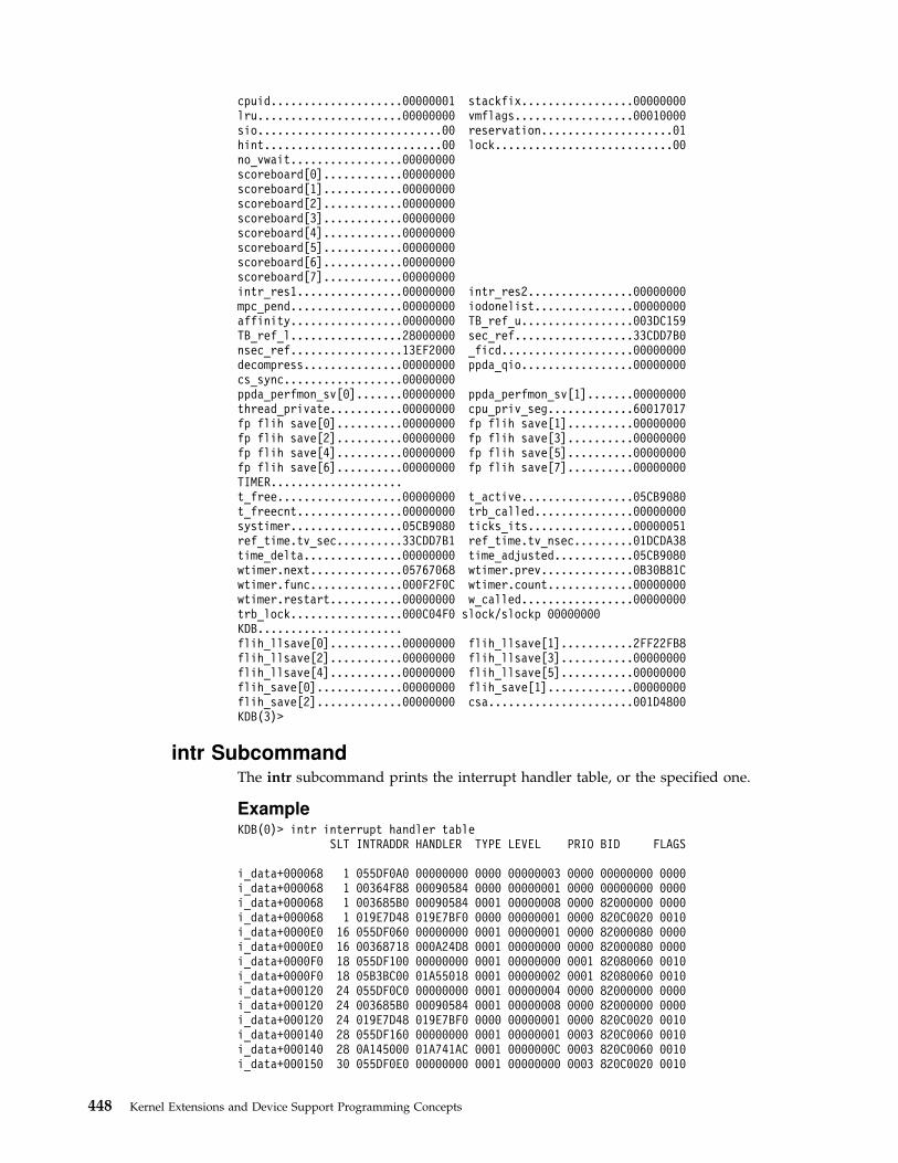
cpuid....................00000001 stackfix.................00000000lru......................00000000 vmflags..................00010000sio............................00 reservation....................01hint...........................00 lock...........................00no_vwait.................00000000scoreboard[0]............00000000scoreboard[1]............00000000scoreboard[2]............00000000scoreboard[3]............00000000scoreboard[4]............00000000scoreboard[5]............00000000scoreboard[6]............00000000scoreboard[7]............00000000intr_res1................00000000 intr_res2................00000000mpc_pend.................00000000 iodonelist...............00000000affinity.................00000000 TB_ref_u.................003DC159TB_ref_l.................28000000 sec_ref..................33CDD7B0nsec_ref.................13EF2000 _ficd....................00000000decompress...............00000000 ppda_qio.................00000000cs_sync..................00000000ppda_perfmon_sv[0].......00000000 ppda_perfmon_sv[1].......00000000thread_private...........00000000 cpu_priv_seg.............60017017fp flih save[0]..........00000000 fp flih save[1]..........00000000fp flih save[2]..........00000000 fp flih save[3]..........00000000fp flih save[4]..........00000000 fp flih save[5]..........00000000fp flih save[6]..........00000000 fp flih save[7]..........00000000TIMER....................t_free...................00000000 t_active.................05CB9080t_freecnt................00000000 trb_called...............00000000systimer.................05CB9080 ticks_its................00000051ref_time.tv_sec..........33CDD7B1 ref_time.tv_nsec.........01DCDA38time_delta...............00000000 time_adjusted............05CB9080wtimer.next..............05767068 wtimer.prev..............0B30B81Cwtimer.func..............000F2F0C wtimer.count.............00000000wtimer.restart...........00000000 w_called.................00000000trb_lock.................000C04F0 slock/slockp 00000000KDB......................flih_llsave[0]...........00000000 flih_llsave[1]...........2FF22FB8flih_llsave[2]...........00000000 flih_llsave[3]...........00000000flih_llsave[4]...........00000000 flih_llsave[5]...........00000000flih_save[0].............00000000 flih_save[1].............00000000flih_save[2].............00000000 csa......................001D4800KDB(3)>
intr SubcommandThe intr subcommand prints the interrupt handler table, or the specified one.
ExampleKDB(0)> intr interrupt handler table
SLT INTRADDR HANDLER TYPE LEVEL PRIO BID FLAGS
i_data+000068 1 055DF0A0 00000000 0000 00000003 0000 00000000 0000i_data+000068 1 00364F88 00090584 0000 00000001 0000 00000000 0000i_data+000068 1 003685B0 00090584 0001 00000008 0000 82000000 0000i_data+000068 1 019E7D48 019E7BF0 0000 00000001 0000 820C0020 0010i_data+0000E0 16 055DF060 00000000 0001 00000001 0000 82000080 0000i_data+0000E0 16 00368718 000A24D8 0001 00000000 0000 82000080 0000i_data+0000F0 18 055DF100 00000000 0001 00000000 0001 82080060 0010i_data+0000F0 18 05B3BC00 01A55018 0001 00000002 0001 82080060 0010i_data+000120 24 055DF0C0 00000000 0001 00000004 0000 82000000 0000i_data+000120 24 003685B0 00090584 0001 00000008 0000 82000000 0000i_data+000120 24 019E7D48 019E7BF0 0000 00000001 0000 820C0020 0010i_data+000140 28 055DF160 00000000 0001 00000001 0003 820C0060 0010i_data+000140 28 0A145000 01A741AC 0001 0000000C 0003 820C0060 0010i_data+000150 30 055DF0E0 00000000 0001 00000000 0003 820C0020 0010
448 Kernel Extensions and Device Support Programming Concepts

i_data+000150 30 055FC000 019E7AA8 0001 0000000E 0003 820C0020 0010i_data+000160 32 055DF080 00000000 0001 00000002 0000 82100080 0000i_data+000160 32 00368734 000A24D8 0001 00000000 0000 82100080 0000i_data+0004E0 144 055DF020 00000000 0002 00000000 0000 00000000 0011i_data+0004E0 144 00368560 000903B0 0002 00000002 0000 00000000 0011i_data+000530 154 055DF040 00000000 0002 FFFFFFFF 000A 00000000 0011i_data+000530 154 00368580 000903B0 0002 00000002 000A 00000000 0011KDB(0)> intr 1 interrupt handler slot 1
SLT INTRADDR HANDLER TYPE LEVEL PRIO BID FLAGS
i_data+000068 1 055DF0A0 00000000 0000 00000003 0000 00000000 0000i_data+000068 1 00364F88 00090584 0000 00000001 0000 00000000 0000i_data+000068 1 003685B0 00090584 0001 00000008 0000 82000000 0000i_data+000068 1 019E7D48 019E7BF0 0000 00000001 0000 820C0020 0010KDB(0)> intr 00368560 interrupt handler address ..addr.......... 00368560 handler....... 000903B0 i_hwassist_int+000000bid........... 00000000 bus_type...... 00000002 PLANARnext.......... 00000000 flags......... 00000011 NOT_SHARED MPSAFElevel......... 00000002 priority...... 00000000 INTMAXi_count....... 00000014KDB(0)>
mst SubcommandThe mst subcommand prints the current context (Machine State Save Area), or thespecified one. Argument is given to identify a process/thread mst context. If -aoption is specified, argument is an effective address, not a slot entry.
ExampleKDB(0)> mst current mstMachine State Save Areaiar : 0002599C msr : 00009030 cr : 20000000 lr : 000259B8ctr : 000258EC xer : 00000000 mq : 00000000r0 : 00000000 r1 : 2FF3B338 r2 : 002E65E0 r3 : 00000003 r4 : 00000002r5 : 00000006 r6 : 002E6750 r7 : 00000000 r8 : DEADBEEF r9 : DEADBEEFr10 : DEADBEEF r11 : 00000000 r12 : 00009030 r13 : DEADBEEF r14 : DEADBEEFr15 : DEADBEEF r16 : DEADBEEF r17 : DEADBEEF r18 : DEADBEEF r19 : DEADBEEFr20 : DEADBEEF r21 : DEADBEEF r22 : DEADBEEF r23 : DEADBEEF r24 : DEADBEEFr25 : DEADBEEF r26 : DEADBEEF r27 : DEADBEEF r28 : 000034E0 r29 : 000C6158r30 : 000C0578 r31 : 00005004s0 : 00000000 s1 : 007FFFFF s2 : 0000F00F s3 : 007FFFFF s4 : 007FFFFFs5 : 007FFFFF s6 : 007FFFFF s7 : 007FFFFF s8 : 007FFFFF s9 : 007FFFFFs10 : 007FFFFF s11 : 007FFFFF s12 : 007FFFFF s13 : 0000C00C s14 : 00004004s15 : 007FFFFFprev 00000000 kjmpbuf 00000000 stackfix 00000000 intpri 0Bcurid 00000306 sralloc E01E0000 ioalloc 00000000 backt 00flags 00 tid 00000000 excp_type 00000000fpscr 00000000 fpeu 00 fpinfo 00 fpscrx 00000000o_iar 00000000 o_toc 00000000 o_arg1 00000000excbranch 00000000 o_vaddr 00000000 mstext 00000000Except :csr 2FEC6B78 dsisr 40000000 bit set: DSISR_PFTsrval 000019DD dar 2FEC6B78 dsirr 00000106KDB(0)> mst 1 slot 1 is thread+0000A0Machine State Save Areaiar : 00038ED0 msr : 00001030 cr : 2A442424 lr : 00038ED0ctr : 002BCC00 xer : 00000000 mq : 00000000r0 : 60017017 r1 : 2FF3B300 r2 : 002E65E0 r3 : 00000000 r4 : 00000002r5 : E60000BC r6 : 00000109 r7 : 00000000 r8 : 000C0300 r9 : 00000001r10 : 2FF3B380 r11 : 00000000 r12 : 00001030 r13 : 00000001 r14 : 2FF22F54r15 : 2FF22F5C r16 : DEADBEEF r17 : DEADBEEF r18 : 0000040F r19 : 00000000r20 : 00000000 r21 : 00000003 r22 : 01000001 r23 : 00000001 r24 : 00000000r25 : E600014C r26 : 000D1A08 r27 : 00000000 r28 : E3000160 r29 : E60000BCr30 : 00000004 r31 : 00000004s0 : 00000000 s1 : 007FFFFF s2 : 0000A00A s3 : 007FFFFF s4 : 007FFFFFs5 : 007FFFFF s6 : 007FFFFF s7 : 007FFFFF s8 : 007FFFFF s9 : 007FFFFF
Chapter 17. Debugging Tools 449

s10 : 007FFFFF s11 : 007FFFFF s12 : 007FFFFF s13 : 6001F01F s14 : 00004004s15 : 60004024prev 00000000 kjmpbuf 00000000 stackfix 2FF3B300 intpri 00curid 00000001 sralloc E01E0000 ioalloc 00000000 backt 00flags 00 tid 00000000 excp_type 00000000fpscr 00000000 fpeu 00 fpinfo 00 fpscrx 00000000o_iar 00000000 o_toc 00000000 o_arg1 00000000excbranch 00000000 o_vaddr 00000000 mstext 00000000Except :csr 30002F00 dsisr 40000000 bit set: DSISR_PFTsrval 6000A00A dar 20022000 dsirr 00000106KDB(0)> set 11 64-bit printing mode64_bit is trueKDB(0)> sw u select user contextKDB(0)> mst print user contextMachine State Save Areaiar : 08000001000581D4 msr : 800000004000D0B0 cr : 84002222lr : 000000010000047C ctr : 08000001000581D4 xer : 00000000mq : 00000000 asr : 0000000013619001r0 : 08000001000581D4 r1 : 0FFFFFFFFFFFFF00 r2 : 080000018007BC80r3 : 0000000000000064 r4 : 0000000000989680 r5 : 0000000000000000r6 : 800000000000D0B0 r7 : 0000000000000000 r8 : 000000002FF9E008r9 : 0000000013619001 r10 : 000000002FF3B010 r11 : 0000000000000000r12 : 0800000180076A98 r13 : 0000000110003730 r14 : 0000000000000001r15 : 00000000200FEB78 r16 : 00000000200FEB88 r17 : BADC0FFEE0DDF00Dr18 : BADC0FFEE0DDF00D r19 : BADC0FFEE0DDF00D r20 : BADC0FFEE0DDF00Dr21 : BADC0FFEE0DDF00D r22 : BADC0FFEE0DDF00D r23 : BADC0FFEE0DDF00Dr24 : BADC0FFEE0DDF00D r25 : BADC0FFEE0DDF00D r26 : BADC0FFEE0DDF00Dr27 : BADC0FFEE0DDF00D r28 : BADC0FFEE0DDF00D r29 : BADC0FFEE0DDF00Dr30 : BADC0FFEE0DDF00D r31 : 0000000110000688s0 : 60000000 s1 : 007FFFFF s2 : 60010B68 s3 : 007FFFFF s4 : 007FFFFFs5 : 007FFFFF s6 : 007FFFFF s7 : 007FFFFF s8 : 007FFFFF s9 : 007FFFFFs10 : 007FFFFF s11 : 007FFFFF s12 : 007FFFFF s13 : 007FFFFF s14 : 007FFFFFs15 : 007FFFFFprev 00000000 kjmpbuf 00000000 stackfix 2FF3B2A0 intpri 00curid 00006FBC sralloc A0000000 ioalloc 00000000 backt 00flags 00 tid 00000000 excp_type 00000000fpscr 00000000 fpeu 00 fpinfo 00 fpscrx 00000000o_iar 00000000 o_toc 00000000 o_arg1 00000000excbranch 00000000 o_vaddr 00000000 mstext 00062C08Except : dar 08000001000581D4KDB(0)>
proc SubcommandThe p subcommand prints the proc table. The ’*’ argument specifies all the table,no argument specifies the current process. Output is decimal or hexadecimal,according to the hexadecimal_wanted toggle value. The current process is shownwith a ″*″.
ExampleKDB(0)> p * print proc table
SLOT NAME STATE PID PPID PGRP UID EUID ADSPACEproc+000000 0 swapper ACTIVE 00000 00000 00000 00000 00000 00001C07proc+000100 1 init ACTIVE 00001 00000 00000 00000 00000 00001405proc+000200 2*wait ACTIVE 00204 00000 00000 00000 00000 00002008proc+000300 3 wait ACTIVE 00306 00000 00000 00000 00000 00002409proc+000400 4 wait ACTIVE 00408 00000 00000 00000 00000 0000280Aproc+000500 5 wait ACTIVE 0050A 00000 00000 00000 00000 00002C0Bproc+000600 6 wait ACTIVE 0060C 00000 00000 00000 00000 0000300Cproc+000700 7 wait ACTIVE 0070E 00000 00000 00000 00000 0000340Dproc+000800 8 wait ACTIVE 00810 00000 00000 00000 00000 0000380Eproc+000900 9 wait ACTIVE 00912 00000 00000 00000 00000 00003C0Fproc+000A00 10 lrud ACTIVE 00A14 00000 00000 00000 00000 00004010proc+000B00 11 netm ACTIVE 00B16 00000 00000 00000 00000 00001806proc+000C00 12 gil ACTIVE 00C18 00000 00000 00000 00000 00004C13
450 Kernel Extensions and Device Support Programming Concepts

proc+000F00 15 lvmb ACTIVE 00F70 00000 00D68 00000 00000 00004832proc+001000 16 biod ACTIVE 01070 02066 02066 00000 00000 000021A8proc+001100 17 biod ACTIVE 0116E 02066 02066 00000 00000 000011A4proc+001200 18 errdemon ACTIVE 01220 00001 01220 00000 00000 00001104proc+001300 19 dump ACTIVE 01306 00001 00ECC 00000 00000 00005C77proc+001400 20 syncd ACTIVE 01418 00001 00ECC 00000 00000 00000D03proc+001500 21 biod ACTIVE 0156C 02066 02066 00000 00000 000001A0KDB(0)> p 21 print process slot 21
SLOT NAME STATE PID PPID PGRP UID EUID ADSPACEproc+001500 21 biod ACTIVE 0156C 02066 02066 00000 00000 000001A0NAME....... biodSTATE...... stat :07...... xstat :0000FLAGS...... flag :00040001 LOAD ORPHANPGRP........... int :00000000........... atomic:00000000LINKS...... child :00000000........... siblings :E3001800 proc+001800........... uidl :E3001500 proc+001500........... ganchor :00000000THREAD..... threadlist :E6001200 thread+001200........... threadcount:0001................. active :0001........... suspended :0000................. terminating:0000........... local :0000SCHEDULE... nice : 20 sched_pri :127DISPATCH... pevent :00000000........... synch :FFFFFFFFIDENTIFIER. uid :00000000............. suid :00000000........... pid :0000156C............. ppid :00002066(0)> more (|C to quit) ? continue........... sid :00002066............. pgrp :00002066MISC....... lock :00000000............. kstackseg :007FFFFF........... adspace :000001A0............. ipc :00000000........... pgrpl :E3001800 proc+001800........... ttyl :00000000........... dblist :00000000........... dbnext :00000000SIGNAL..... pending :........... sigignore: URG IO WINCH PWR........... sigcatch : TERM USR1 USR2STATISTICS. page size :00000000............. pctcpu :00000000........... auditmask :00000000........... minflt :00000004............. majflt :00000000SCHEDULER.. repage :00000000............. sched_count:00000000........... sched_next :00000000........... sched_back :00000000........... cpticks :0000................. msgcnt :0000........... majfltsec :00000000THE FOLLOWING EXAMPLE SHOWS HOW TO FIND A THREAD THRU THE PROCESS TABLE.The initial problem was that many threads are waiting for ever.This example shows how to point the failing process:KDB(6)> th -w WPGIN threads waiting for VMM resources
SLOT NAME STATE TID PRI CPUID CPU FLAGS WCHANthread+000780 10 lrud SLEEP 00A15 010 000 00001004 vmmdseg+69C84D0thread+0012C0 25 dtlogin SLEEP 01961 03C 000 00000000 vmmdseg+69C8670thread+001500 28 cnsview SLEEP 01C71 03C 000 00000004 vmmdseg+69C8670thread+00B1C0 237 jfsz SLEEP 0EDCD 032 000 00001000 vm_zqevent+000000thread+00C240 259 jfsc SLEEP 10303 01E 000 00001000 _$STATIC+000110thread+00E940 311 rm SLEEP 137C3 03C 000 00000000 vmmdseg+69C8670thread+012300 388 touch SLEEP 1843B 03C 000 00000000 vmmdseg+69C8670...thread+0D0F80 4458 link_fil SLEEP 116A39 03C 000 00000000 vmmdseg+69C9C74thread+0DC140 4695 sync SLEEP 1257BB 03C 000 00000000 vmmdseg+69C8670thread+0DD280 4718 touch SLEEP 126E57 03C 000 00000000 vmmdseg+69C8670thread+0E5A40 4899 renamer SLEEP 132315 03C 000 00000000 vmmdseg+69C8670thread+0EE140 5079 renamer SLEEP 13D7C3 03C 000 00000000 vmmdseg+69C8670thread+0F03C0 5125 renamer SLEEP 1405B7 03C 000 00000000 vmmdseg+69C8670thread+0FC540 5383 renamer SLEEP 15072F 03C 000 00000000 vmmdseg+69C8670
Chapter 17. Debugging Tools 451

thread+101AC0 5497 renamer SLEEP 157909 03C 000 00000000 vmmdseg+69C8670thread+10D280 5742 rm SLEEP 166E37 03C 000 00000000 vmmdseg+69C8670KDB(6)> vmwait vmmdseg+69C8670 VMM resourceVMM Wait InfoWaiting on transactions to end to forward the logKDB(6)> vmwait vmmdseg+69C9C74 VMM resourceVMM Wait InfoWaiting on transaction block number 00000057KDB(6)> tblk 87 print transaction block number
@tblk[87] vmmdseg +69C9C3Clogtid.... 002C77CF next...... 00000064 tid....... 00000057 flag...... 00000000cpn....... 00000000 ceor...... 00000000 cxor...... 00000000 csn....... 00000000waitsid... 00000000 waitline.. 00000000 locker.... 00000000 lsidx..... 00000AB3logage.... 00B71704 gcwait.... FFFFFFFF waitors... E60D0F80 cqnext.... 00000000TID is registered in __ublock, at page offset 0x6a0.Search in physical memory TID 0x00000057.The search is limited at this page offset.KDB(6)> findp 6A0 00000057 ffffffff 1000 physical search0AFC86A0: 00000057 00000000 00000000 00000000KDB(6)> pft 1 print page frame informationEnter the page frame number (in hex): 0AFC8VMM PFT Entry For Page Frame 0AFC8 of 7FF67pte = B066F458, pvt = B202BF20, pft = B3A0F580h/w hashed sid : 000164EA pno : 0000FF3B key : 0source sid : 000164EA pno : 0000FF3B key : 0> in use> on scb list> valid (h/w)> referenced (pft/pvt/pte): 0/1/1> modified (pft/pvt/pte): 0/1/1page number in scb (pagex) : 0000FF3Bdisk block number (dblock) : 00000000next page on scb list (sidfwd) : FFFFFFFFprev page on scb list (sidbwd) : 00051257freefwd/waitlist (freefwd): 00000000freebwd/logage/pincnt (freebwd): 00010000out of order I/O (nonfifo): 0000next frame i/o list (nextio) : 00000000storage attributes (wimg) : 2xmem hide count (xmemcnt): 0next page on s/w hash (next) : FFFFFFFFList of alias entries (alist) : 0000FFFFindex in PDT (devid) : 0000The Segment ID of __ublock is the ADSPACE of the processKDB(6)> find proc 000164EA search this SID in the proc tableproc+10EB58: 000164EA E3173F00 00000000 00000000KDB(6)> proc proc+10EB00 print the process entry
SLOT NAME STATE PID PPID PGRP UID EUID ADSPACEproc+10EB00 4331 renamer ACTIVE 10EB98 D6282 065DE 00000 00000 000164EANAME....... renamerSTATE...... stat :07...... xstat :0000FLAGS...... flag :00000001 LOAD........... int :00000000........... atomic:00000000LINKS...... child :00000000........... siblings :E3173F00 proc+173F00........... uidl :E310EB00 proc+10EB00........... ganchor :00000000THREAD..... threadlist :E60F2640 thread+0F2640...KDB(6)> sw thread+0F2640 switch to this threadSwitch to thread: <thread+0F2640>KDB(6)> f look at the stackthread+0F2640 STACK:[000D4950]slock_instr_ppc+00045C (C0042BDF, 00000002 [??])[000095AC].simple_lock+0000AC ()[00202370]logmvc+00004C (??, ??, ??, ??)
452 Kernel Extensions and Device Support Programming Concepts
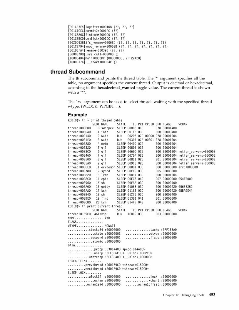
[001C23F4]logafter+000108 (??, ??, ??)[001C1CEC]commit2+0001FC (??)[001C386C]finicom+0000C0 (??, ??)[001C3BC0]comlist+0001CC (??, ??)[0020D938]jfs_rename+0006EC (??, ??, ??, ??, ??, ??, ??)[001CE794]vnop_rename+000038 (??, ??, ??, ??, ??, ??, ??)[001DEFA4]rename+000398 (??, ??)[000037D8].sys_call+000000 ()[100004B4]main+0002DC (00000006, 2FF22A20)[10000174].__start+00004C ()
thread SubcommandThe th subcommand prints the thread table. The ’*’ argument specifies all thetable, no argument specifies the current thread. Output is decimal or hexadecimal,according to the hexadecimal_wanted toggle value. The current thread is shownwith a ″*″.
The ’-w’ argument can be used to select threads waiting with the specified threadwtype, (WLOCK, WPGIN, ...).
ExampleKDB(0)> th * print thread table
SLOT NAME STATE TID PRI CPUID CPU FLAGS WCHANthread+000000 0 swapper SLEEP 00003 010 078 00001400thread+0000A0 1 init SLEEP 001F3 03C 000 00000400thread+000140 2 wait RUN 00205 07F 00000 078 00001004thread+0001E0 3 wait RUN 00307 07F 00001 078 00001004thread+000280 4 netm SLEEP 00409 024 000 00001004thread+000320 5 gil SLEEP 0050B 025 000 00001004thread+0003C0 6 gil SLEEP 0060D 025 000 00001004 netisr_servers+000000thread+000460 7 gil SLEEP 0070F 025 000 00001004 netisr_servers+000000thread+000500 8 gil SLEEP 00811 025 001 00001004 netisr_servers+000000thread+0005A0 9 gil SLEEP 00913 025 000 00001004 netisr_servers+000000thread+0006E0 11 errdemon SLEEP 00B01 03C 000 00000000 errc+000008thread+000780 12 syncd SLEEP 00CF9 03C 005 00000000thread+000820 13 lvmb SLEEP 00D97 03C 000 00001004thread+0008C0 14 cpio SLEEP 00EC3 040 007 00000000 054FB000thread+000960 15 sh SLEEP 00FAF 03C 000 00000400thread+000A00 16 getty SLEEP 01065 03C 000 00000420 0563525Cthread+000AA0 17 ksh SLEEP 01163 03C 000 00000420 05BA0E44thread+000B40 18 sh SLEEP 01279 03C 000 00000400thread+000BE0 19 find SLEEP 013B1 041 001 00000000thread+000C80 20 ksh SLEEP 014FB 040 000 00000400KDB(0)> th print current thread
SLOT NAME STATE TID PRI CPUID CPU FLAGS WCHANthread+0159C0 461*ksh RUN 1CDC9 03D 003 00000000NAME................ kshFLAGS...............WTYPE............... NOWAIT............stackp64 :00000000 ..............stackp :2FF1E5A0...............state :00000002 ...............wtype :00000000.............suspend :00000001 ...............flags :00000000..............atomic :00000000DATA...............................procp :E3014400 <proc+014400>...............userp :2FF3B6C0 <__ublock+0002C0>............uthreadp :2FF3B400 <__ublock+000000>THREAD LINK...................prevthread :E60159C0 <thread+0159C0>..........nextthread :E60159C0 <thread+0159C0>SLEEP LOCK.....................ulock64 :00000000 ..............ulock :00000000...............wchan :00000000 ..............wchan1 :00000000...........wchan1sid :00000000 ........wchan1offset :00000000
Chapter 17. Debugging Tools 453

(3)> more (|C to quit) ? continue..............wchan2 :00000000 ..............swchan :00000000...........eventlist :00000000 ..............result :00000000.............polevel :00000000 .............pevent :00000000.............wevent :00000000 ..............slist :00000000...........lockcount :00000002DISPATCH...........................ticks :00000000 ...............prior :E60159C0................next :E60159C0 ...............synch :FFFFFFFF..............dispct :00000003 ...............fpuct :00000000SCHEDULER..........................cpuid :FFFFFFFF ..............scpuid :FFFFFFFF............affinity :00000001 .................pri :0000003C..............policy :00000000 .................cpu :00000000.............lockpri :0000003D .............wakepri :0000007F................time :000000FF .............sav_pri :0000003CSIGNAL............................cursig :00000000......(pending) sig :............sigmask :...............scp64 :00000000 .................scp :00000000MISC............................graphics :00000000 ..............cancel :00000000(3)> more (|C to quit) ? continue...........lockowner :00000000 .............boosted :00000000..............tsleep :FFFFFFFF..........userdata64 :00000000 ............userdata :00000000KDB(0)> th -w print -w usageMissing wtype:NOWAITWEVENTWLOCKWTIMERWCPUWPGINWPGOUTWPLOCKWFREEFWMEMWLOCKREADWUEXCEPTKDB(0)> th -w WPGIN print threads waiting for page-in
SLOT NAME STATE TID PRI CPUID CPU FLAGS WCHANthread+000600 8 lrud SLEEP 00811 010 000 00001004 vmmdseg+69C84D0thread+000E40 19 syncd SLEEP 01329 03D 003 00000000 vmmdseg+69D1630thread+013440 411 oracle SLEEP 19B75 03D 002 00000000 vmmdseg+69F171Cthread+013500 412 oracle SLEEP 19C77 03F 006 00000000 vmmdseg+69F13A8thread+022740 735 rts32 SLEEP 2DF7F 03F 007 00000000 vmmdseg+3A9A5B8KDB(0)> vmwait vmmdseg+69C84D0 print VMM resource the thread is waiting forVMM Wait InfoWaiting on lru daemon anchorKDB(0)> vmwait vmmdseg+69D1630 print VMM resource the thread is waiting forVMM Wait InfoWaiting on segment I/O level (v_iowait), sidx = 00000124KDB(0)> vmwait vmmdseg+69F171C print VMM resource the thread is waiting forVMM Wait InfoWaiting on segment I/O level (v_iowait), sidx = 000008AFKDB(0)> vmwait vmmdseg+69F13A8 print VMM resource the thread is waiting forVMM Wait InfoWaiting on segment I/O level (v_iowait), sidx = 000008A2KDB(0)> vmwait vmmdseg+3A9A5B8 print VMM resource the thread is waiting forVMM Wait InfoWaiting on page frame number 0000DE1EKDB(1)> th -w WLOCK print threads waiting for locks
SLOT NAME STATE TID PRI CPUID CPU FLAGS WCHANthread+0000C0 1 init SLEEP 001BD 03C 000 00000000 cred_lock+000000
lockhsque+000020
454 Kernel Extensions and Device Support Programming Concepts
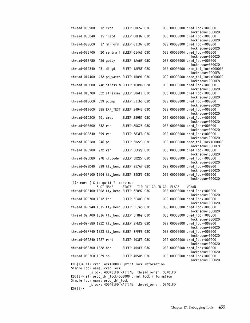
thread+000900 12 cron SLEEP 00C57 03C 000 00000000 cred_lock+000000lockhsque+000020
thread+000B40 15 inetd SLEEP 00FB7 03C 000 00000000 cred_lock+000000lockhsque+000020
thread+000CC0 17 mirrord SLEEP 01107 03C 000 00000000 cred_lock+000000lockhsque+000020
thread+000F00 20 sendmail SLEEP 014A5 03C 000 00000004 cred_lock+000000lockhsque+000020
thread+013F80 426 getty SLEEP 1AA6F 03C 000 00000000 cred_lock+000000lockhsque+000020
thread+014340 431 diagd SLEEP 1AF8F 03C 000 00000000 proc_tbl_lock+000000lockhsque+0000F8
thread+014400 432 pd_watch SLEEP 1B091 03C 000 00000000 proc_tbl_lock+000000lockhsque+0000F8
thread+015000 448 stress_m SLEEP 1C08B 028 000 00000000 cred_lock+000000lockhsque+000020
thread+018780 522 stresser SLEEP 20AF1 03C 000 00000000 cred_lock+000000lockhsque+000020
thread+018CC0 529 pcomp SLEEP 21165 03C 000 00000000 cred_lock+000000lockhsque+000020
thread+01B6C0 585 EXP_TEST SLEEP 24943 03C 000 00000000 cred_lock+000000lockhsque+000020
thread+01C2C0 601 cres SLEEP 25957 03C 000 00000000 cred_lock+000000lockhsque+000020
thread+022500 732 rsh SLEEP 2DC25 03C 000 00000000 cred_lock+000000lockhsque+000020
thread+02A240 899 rcp SLEEP 383FB 03C 000 00000000 cred_lock+000000lockhsque+000020
thread+02C580 946 ps SLEEP 3B223 03C 000 00000000 proc_tbl_lock+000000lockhsque+0000F8
thread+02D900 972 rsh SLEEP 3CC29 03C 000 00000000 cred_lock+000000lockhsque+000020
thread+02DD80 978 xlCcode SLEEP 3D227 03C 000 00000000 cred_lock+000000lockhsque+000020
thread+02ED40 999 tty_benc SLEEP 3E7A7 03C 000 00000000 cred_lock+000000lockhsque+000020
thread+02F100 1004 tty_benc SLEEP 3ECF3 03C 000 00000000 cred_lock+000000lockhsque+000020
(1)> more (|C to quit) ? continueSLOT NAME STATE TID PRI CPUID CPU FLAGS WCHAN
thread+02F400 1008 tty_benc SLEEP 3F097 03C 000 00000000 cred_lock+000000lockhsque+000020
thread+02F700 1012 ksh SLEEP 3F403 03C 000 00000000 cred_lock+000000lockhsque+000020
thread+02F940 1015 tty_benc SLEEP 3F745 03C 000 00000000 cred_lock+000000lockhsque+000020
thread+02FA00 1016 tty_benc SLEEP 3F869 03C 000 00000000 cred_lock+000000lockhsque+000020
thread+02FE80 1022 tty_benc SLEEP 3FECB 03C 000 00000000 cred_lock+000000lockhsque+000020
thread+02FF40 1023 tty_benc SLEEP 3FFF5 03C 000 00000000 cred_lock+000000lockhsque+000020
thread+030240 1027 rshd SLEEP 403F3 03C 000 00000000 cred_lock+000000lockhsque+000020
thread+030300 1028 bsh SLEEP 404FF 03C 000 00000000 cred_lock+000000lockhsque+000020
thread+0303C0 1029 sh SLEEP 40505 03C 000 00000000 cred_lock+000000lockhsque+000020
KDB(1)> slk cred_lock+000000 print lock informationSimple lock name: cred_lock
_slock: 400401FD WAITING thread_owner: 00401FDKDB(1)> slk proc_tbl_lock+000000 print lock informationSimple lock name: proc_tbl_lock
_slock: 400401FD WAITING thread_owner: 00401FDKDB(1)>
Chapter 17. Debugging Tools 455

ttid and tpid SubcommandsThe ttid subcommand prints the thread entry selected by thread id. Default is thecurrent thread. The tpid subcommand prints all thread entries selected by processid. Default is the current process.Id input is decima hexadecimal, according to thehexadecimal_wanted toggle value.
ExampleKDB(4)> p * print process table
SLOT NAME STATE PID PPID PGRP UID EUID ADSPACE...proc+000100 1 init ACTIVE 00001 00000 00000 00000 00000 0000A005...proc+000C00 12 gil ACTIVE 00C18 00000 00000 00000 00000 00026013...KDB(4)> tpid 1 print thread(s) of process pid 1
SLOT NAME STATE TID PRI CPUID CPU FLAGS WCHANthread+0000C0 1 init SLEEP 001D9 03C 000 00000400KDB(4)> tpid 00C18 print thread(s) of process pid 0xc18
SLOT NAME STATE TID PRI CPUID CPU FLAGS WCHANthread+000900 12 gil SLEEP 00C19 025 000 00001004thread+000C00 16 gil SLEEP 01021 025 00000 000 00003004 netisr_servers+000000thread+000B40 15 gil SLEEP 00F1F 025 00000 000 00003004 netisr_servers+000000thread+000A80 14 gil SLEEP 00E1D 025 00000 000 00003004 netisr_servers+000000thread+0009C0 13 gil SLEEP 00D1B 025 00000 000 00003004 netisr_servers+000000KDB(4)> ttid 001D9 print thread with tid 0x1d9
SLOT NAME STATE TID PRI CPUID CPU FLAGS WCHANthread+0000C0 1 init SLEEP 001D9 03C 000 00000400NAME................ initFLAGS............... WAKEONSIGWTYPE............... WEVENT............stackp64 :00000000 ..............stackp :2FF22DC0...............state :00000003 ...............wtype :00000001.............suspend :00000001 ...............flags :00000400..............atomic :00000000DATA...............................procp :E3000100 <proc+000100>...............userp :2FF3B6C0 <__ublock+0002C0>............uthreadp :2FF3B400 <__ublock+000000>THREAD LINK...................prevthread :E60000C0 <thread+0000C0>..........nextthread :E60000C0 <thread+0000C0>SLEEP LOCK.....................ulock64 :00000000 ..............ulock :00000000...............wchan :00000000 ..............wchan1 :00000000...........wchan1sid :00000000 ........wchan1offset :01AB5A58(4)> more (|C to quit) ? continue..............wchan2 :00000000 ..............swchan :00000000...........eventlist :00000000 ..............result :00000000.............polevel :000000AF .............pevent :00000000.............wevent :00000004 ..............slist :00000000...........lockcount :00000000DISPATCH...........................ticks :00000000 ...............prior :E60000C0................next :E60000C0 ...............synch :FFFFFFFF..............dispct :000008F6 ...............fpuct :00000000SCHEDULER..........................cpuid :FFFFFFFF ..............scpuid :FFFFFFFF............affinity :00000001 .................pri :0000003C..............policy :00000000 .................cpu :00000000.............lockpri :0000003D .............wakepri :0000007F................time :000000FF .............sav_pri :0000003CSIGNAL............................cursig :00000000......(pending) sig :............sigmask :
456 Kernel Extensions and Device Support Programming Concepts
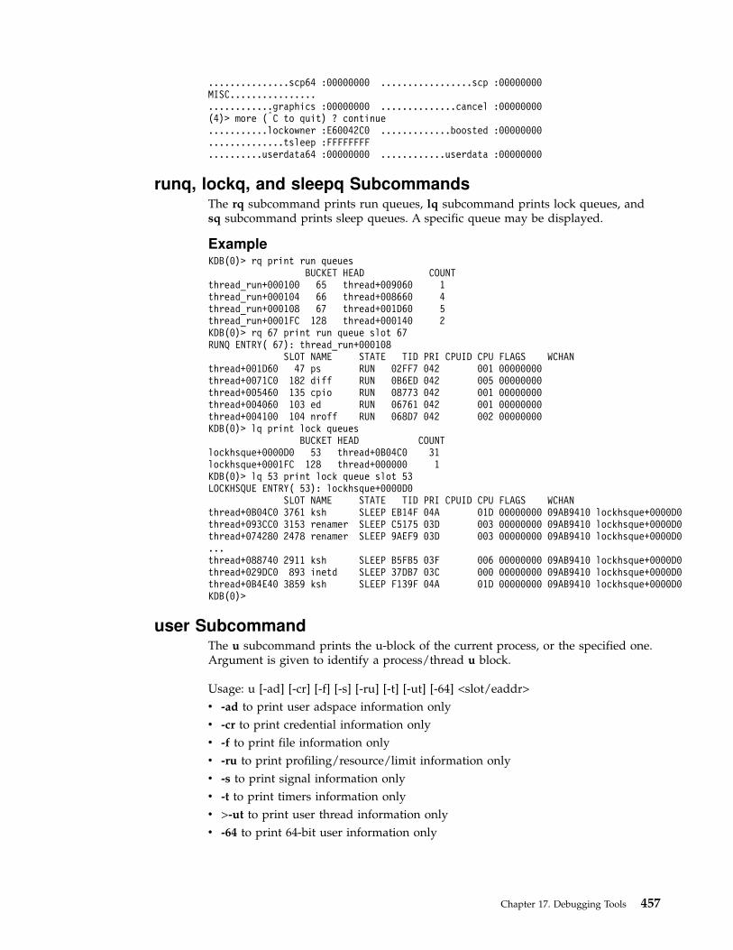
...............scp64 :00000000 .................scp :00000000MISC............................graphics :00000000 ..............cancel :00000000(4)> more (|C to quit) ? continue...........lockowner :E60042C0 .............boosted :00000000..............tsleep :FFFFFFFF..........userdata64 :00000000 ............userdata :00000000
runq, lockq, and sleepq SubcommandsThe rq subcommand prints run queues, lq subcommand prints lock queues, andsq subcommand prints sleep queues. A specific queue may be displayed.
ExampleKDB(0)> rq print run queues
BUCKET HEAD COUNTthread_run+000100 65 thread+009060 1thread_run+000104 66 thread+008660 4thread_run+000108 67 thread+001D60 5thread_run+0001FC 128 thread+000140 2KDB(0)> rq 67 print run queue slot 67RUNQ ENTRY( 67): thread_run+000108
SLOT NAME STATE TID PRI CPUID CPU FLAGS WCHANthread+001D60 47 ps RUN 02FF7 042 001 00000000thread+0071C0 182 diff RUN 0B6ED 042 005 00000000thread+005460 135 cpio RUN 08773 042 001 00000000thread+004060 103 ed RUN 06761 042 001 00000000thread+004100 104 nroff RUN 068D7 042 002 00000000KDB(0)> lq print lock queues
BUCKET HEAD COUNTlockhsque+0000D0 53 thread+0B04C0 31lockhsque+0001FC 128 thread+000000 1KDB(0)> lq 53 print lock queue slot 53LOCKHSQUE ENTRY( 53): lockhsque+0000D0
SLOT NAME STATE TID PRI CPUID CPU FLAGS WCHANthread+0B04C0 3761 ksh SLEEP EB14F 04A 01D 00000000 09AB9410 lockhsque+0000D0thread+093CC0 3153 renamer SLEEP C5175 03D 003 00000000 09AB9410 lockhsque+0000D0thread+074280 2478 renamer SLEEP 9AEF9 03D 003 00000000 09AB9410 lockhsque+0000D0...thread+088740 2911 ksh SLEEP B5FB5 03F 006 00000000 09AB9410 lockhsque+0000D0thread+029DC0 893 inetd SLEEP 37DB7 03C 000 00000000 09AB9410 lockhsque+0000D0thread+0B4E40 3859 ksh SLEEP F139F 04A 01D 00000000 09AB9410 lockhsque+0000D0KDB(0)>
user SubcommandThe u subcommand prints the u-block of the current process, or the specified one.Argument is given to identify a process/thread u block.
Usage: u [-ad] [-cr] [-f] [-s] [-ru] [-t] [-ut] [-64] <slot/eaddr>
v -ad to print user adspace information only
v -cr to print credential information only
v -f to print file information only
v -ru to print profiling/resource/limit information only
v -s to print signal information only
v -t to print timers information only
v >-ut to print user thread information only
v -64 to print 64-bit user information only
Chapter 17. Debugging Tools 457

ExampleKDB(0)> u -ut print current user thread blockUser thread context [2FF3B400]:
save.... @ 2FF3B400 fpr..... @ 2FF3B550Uthread System call state:
msr64......00000000 msr........0000D0B0errnopp64..00000000 errnopp....200FEFE8 error......00scsave[0]..2004A474 scsave[1]..00000020 scsave[2]..20007B48scsave[3]..2FF22AA0 scsave[4]..00000014 scsave[5]..20006B68scsave[6]..2004A7B4 scsave[7]..2004A474kstack.....2FF3B400 audsvc.....00000000flags:
Uthread Miscellaneous stuff:fstid.....00000000 ioctlrv...00000000 selchn....00000000link......00000000 loginfo...00000000fselchn...00000000 selbuc........0000context64.00000000 context...00000000sigssz64..00000000 sigssz....00000000stkb64....00000000 stkb......00000000jfscr.....00000000
Uthread Signal management:sigsp64...00000000 sigsp.....00000000code......00000000 oldmask...0000000000000000
Thread timers:timer[0].................00000000
KDB(0)> u -64 print current 64-bit user part of ublock64-bit process context [2FF7D000]:
stab.......... @ 2FF7D000STAB: esid vsid esid vsid
0 09000000000000B0 000000000714E000 1 0000000000000000 000000000000000016 00000000200000B0 000000000AA75000 17 0000000000000000 000000000000000080 09001000A00000B0 000000000CA99000 81 0000000000000000 0000000000000000104 00000000D00000B0 000000000D95B000 105 0000000000000000 0000000000000000128 00000001000000B0 0000000004288000 129 0000000000000000 0000000000000000136 00000001100000B0 000000000C298000 137 0000000000000000 0000000000000000160 09002001400000B0 000000000E15C000 161 08002001400000B0 0000000008290000248 09FFFFFFF00000B0 0000000002945000 249 08FFFFFFF00000B0 0000000001A83000250 0FFFFFFFF00000B0 000000000BA97000 251 0000000000000000 0000000000000000254 0000000000000000 0000000000000000 255 0000000000000000 0000000000000000
stablock...... @ 2FF7E000 stablock.........00000000mstext.mst64.. @ 2FF7E008 mstext.remaps. @ 2FF7E140
SNODE... @ 2FF7E3C8origin...28020000 freeind..FFFFFFFF nextind..00000002maxind...0006DD82 size.....00000094
UNODE... @ 2FF7E3E0origin...2BFA1000 freeind..FFFFFFFF nextind..0000000Emaxind...000D4393 size.....0000004C
maxbreak...00000001100005B8 minbreak...00000001100005B8maxdata....0000000000000000 exitexec...00000000brkseg.....00000011 stkseg.....FFFFFFFF
KDB(0)> u -f 18 print file decriptor table of thread slot 18fdfree[0].00000000 fdfree[1].00000000 fdfree[2].00000000maxofile..00000008 freefile..00000000fd_lock...2FF3C188 slock/slockp 00000000
File descriptor table at..2FF3C1A0:fd 3 fp..100000C0 count..00000000 flags. ALLOCATEDfd 4 fp..10000180 count..00000001 flags. ALLOCATEDfd 5 fp..100003C0 count..00000000 flags. ALLOCATEDfd 6 fp..100005A0 count..00000000 flags. ALLOCATEDfd 7 fp..10000600 count..00000000 flags. FDLOCK ALLOCATEDRest of File Descriptor Table empty or paged out.
458 Kernel Extensions and Device Support Programming Concepts

LVM Subcommands for the KDB Kernel Debugger and kdb Command
pbuf SubcommandThe pbuf subcommand prints physical buffer information.
Example(0)> pbuf 0ACA4500PBUF............. 0ACA4500pb@............. 0ACA4500 pb_lbuf........ 0A5B8318pb_sched........ 01B64880 pb_pvol........ 05770000pb_bad.......... 00000000 pb_start....... 00133460pb_mirror....... 00000000 pb_miravoid.... 00000000pb_mirbad....... 00000000 pb_mirdone..... 00000000pb_swretry...... 00000000 pb_type........ 00000000pb_bbfixtype.... 00000000 pb_bbop........ 00000000pb_bbstat....... 00000000 pb_whl_stop.... 00000000pb_part......... 00000000 pb_bbcount..... 00000000pb_forw......... 0ACA45A0 pb_back........ 0ACA4460stripe_next..... 0ACA4500 stripe_status.. 00000000orig_addr....... 0C149000 orig_count..... 00001000partial_stripe.. 00000000 first_issued... 00000001orig_bflags..... 000C0000(0)> buf 0A5B8318
DEV VNODE BLKNO FLAGS0 0A5B8318 000A000B 00000000 0007A360 DONE MPSAFE MPSAFE_INITIAL
forw 0000C4C1 back 00000000 av_forw 0A5B98C0 av_back 00000000blkno 0007A360 addr 0C149000 bcount 00001000 resid 00000000error 00000000 work 00080000 options 00000000 event 00000000iodone: v_pfend+000000start.tv_sec 00000000 start.tv_nsec 00000000xmemd.aspace_id 00000000 xmemd.xm_flag 00000000 xmemd.xm_version 00000000xmemd.subspace_id 0080CC5B xmemd.subspace_id2 00000000 xmemd.uaddr 00000000(0)> pbuf * 0ACA4500
PBUF@ LBUF@ PVOL@ DEV START STRIPE OR_ADDR OR_COUNT0ACA4500 0A5B8318 05770000 00120006 00133460 0ACA4500 0C149000 000010000ACA45A0 0AA64898 0A7DB000 00120000 001C71F0 0ACA45A0 0003E000 000010000ACA4640 0A323D10 05766000 00120004 00082FC0 0ACA4640 0A997000 000010000ACA46E0 0A5B97B8 05770000 00120006 001338C8 0AC95320 0C15C000 000010000ACB9400 0AA62630 0A7DB000 00120000 001851A0 0ACB9400 00054000 000010000ACB94A0 0AA65398 0A7BC000 00120001 001AD750 0ACB94A0 083E9000 000010000ACB9540 0AA62DC0 0A7DB000 00120000 00181150 0ACB9540 00000000 000020000ACA0000 0AA6CA20 0A7BC000 00120001 000F72BC 0ACA0000 00000000 000008000ACCD800 0AA64478 0A7DB000 00120000 001C7260 0ACCD800 00000000 000010000ACCD8A0 0A5B86E0 05770000 00120006 00133BA8 0ACCD8A0 0B796000 000020000ACCD940 0A31F210 05766000 00120004 0013B100 0ACCD940 00840000 000020000ACCD9E0 0AA6ADE8 0A7BC000 00120001 0006925C 0ACCD9E0 00000000 000008000ACCDA80 0AA6C028 0A7BC000 00120001 000DA29C 0ACCDA80 003FF000 000008000ACCDB20 0A324DE8 05766000 00120004 0008ACE8 0ACCDB20 0C151000 000010000ACCDBC0 0AA638C0 0A7DB000 00120000 00186228 0ACCDBC0 00000000 00001000...
volgrp SubcommandThe volgrp subcommand prints volume groupe information. volgrp addresses areregistered in the table, in DSDPTR field.
Example(0)> devsw 0aSlot address 0571E280MAJ#00A OPEN CLOSE READ WRITE
01B44DE4 01B44470 01B43CD0 01B43C04IOCTL STRATEGY TTY SELECT01B42B18 .hd_strategy 00000000 .nodevCONFIG PRINT DUMP MPX
Chapter 17. Debugging Tools 459

01B413A0 .nodev .hd_dump .nodevREVOKE DSDPTR SELPTR OPTS.nodev 05762000 00000000 0000000A
(0)> volgrp 05762000VOLGRP............. 05762000vg_lock.................. FFFFFFFF partshift............... 0000000Dopen_count............... 00000013 flags................... 00000000tot_io_cnt............... 00000000 lvols@.................. 05762010pvols@................... 05762410 major_num............... 0000000Avg_id.................... 00920045 005BDB00 00000000 00000000nextvg................... 00000000 opn_pin@................ 057624A8von_pid.................. 00000E78 nxtactvg................ 00000000ca_freepvw............... 00000000 ca_pvwmem............... 00000000ca_hld@.................. 057624D8 ca_pv_wrt@.............. 057624E0ca_inflt_cnt............. 00000000 ca_size................. 00000000ca_pvwblked.............. 00000000 mwc_rec................. 00000000ca_part2................. 00000000 ca_lst.................. 00000000ca_hash@................. 057624F4 bcachwait............... FFFFFFFFecachwait................ FFFFFFFF wait_cnt................ 00000000quorum_cnt............... 00000002 wheel_idx............... 00000000whl_seq_num.............. 00000000 sa_act_lst.............. 00000000sa_hld_lst............... 00000000 vgsa_ptr................ 05776000config_wait.............. FFFFFFFF sa_lbuf@................ 05762534sa_pbuf@................. 0576258C sa_intlock@............. 0576262Csa_intlock............... E8003B80conc_flags............... 00000000 conc_msglock............ 00000000vgsa_ts_prev.tv_sec...... 00000000 vgsa_ts_prev.tv_nsec.... 00000000vgsa_ts_merged.tv_sec.... 00000000 vgsa_ts_merged.tv_nsec.. 00000000vgsa_spare_ptr........... 00000000 intr_notify............. 00000000intr_ok.................. 00000000 intr_tries.............. 00000000resv_tries............... 00000000 sa_updated.............. 00000000re_lbuf@................. 05762660 re_pbuf@................ 057626B8re_idx................... 00000000 re_finish............... 00000000re_twice................. 00000000 re_marks................ 00000000re_saved_marks........... 00000000 refresh_Q@.............. 05762768concsync_wd_pass@........ 05762770 concsync_wd_init@....... 05762788concsync_wd_intr@........ 057627A0 concsync_terminate_Q@... 05762810concsync_lockpart........ 00000000concconfig_lbuf@......... 0576281C concconfig_wd@.......... 05762874concconfig_wd_intr@...... 0576288C concconfig_nodes........ 00000000concconfig_acknodes...... 00000000 concconfig_nacknodes.... 00000000concconfig_event......... 00000000 concconfig_timeout...... 00000000llc.flags................ 00000000 llc.ack................. 00000000llc.nak.................. 00000000 llc.timeout............. 00000000llc.contention........... 00000000 llc.awakened............ 00000000llc.wd@.................. 05762920 llc.event............... 00000000llc.arb_intlock.......... 00000000 llc.arb_intlock@........ 0576293Cdd_conc_reset............ 00000000 @timer_intlock.......... 05762944timer_intlock............ 00000000@vg_intlock.............. 05762948 vg_intlock.............. E8003BA0LVOL............ 05CC8400work_Q.......... 00000000 lv_status...... 00000000lv_options...... 00000001 nparts......... 00000001i_sched......... 00000000 nblocks........ 00040000parts[0]........ 05706A00 pvol@ 05766000 dev 00120004 start 00000000parts[1]........ 00000000parts[2]........ 00000000maxsize......... 00000000 tot_rds........ 00000000complcnt........ 00000000 waitlist....... FFFFFFFFstripe_exp...... 00000000 striping_width. 00000000lvol_intlock.... 00000000 lvol_intlock@.. 05CC8434LVOL............ 05CC8440work_Q.......... 05780D00 lv_status...... 00000002lv_options...... 00000190 nparts......... 00000001i_sched......... 00000000 nblocks........ 00044000parts[0]........ 05706000 pvol@ 05766000 dev 00120004 start 00065100parts[1]........ 00000000
460 Kernel Extensions and Device Support Programming Concepts

parts[2]........ 00000000maxsize......... 00000200 tot_rds........ 00000000complcnt........ 00000000 waitlist....... FFFFFFFFstripe_exp...... 00000000 striping_width. 00000000lvol_intlock.... 00000000 lvol_intlock@.. 05CC8474WORK_Q@ BUF@ FLAGS DEV BLKNO BADDR BCOUNT RESID SID05780D28 0A323580 000C8001 000A0001 00004A08 0FF3A000 00001000 00001000 0080C919WORK_Q@ BUF@ FLAGS DEV BLKNO BADDR BCOUNT RESID SID05780D90 0A323738 000C0000 000A0001 00022420 0B783000 00001000 00001000 0080CC5B05780D90 0A323D10 000C0000 000A0001 00022408 0B782000 00001000 00001000 0080CC5B...LVOL............ 0A752440work_Q.......... 0A82DD00 lv_status...... 00000002lv_options...... 00000000 nparts......... 00000001i_sched......... 00000000 nblocks........ 00002000parts[0]........ 057222F0 pvol@ 0576C000 dev 00120005 start 000C7100parts[1]........ 00000000parts[2]........ 00000000maxsize......... 00000200 tot_rds........ 00000000complcnt........ 00000000 waitlist....... FFFFFFFFstripe_exp...... 00000000 striping_width. 00000000lvol_intlock.... E80279C0 lvol_intlock@.. 0A752474
pvol SubcommandThe pvol subcommand prints physical volume information.
Example(0)> pvol 05766000PVOL............... 05766000dev............... 00120004 xfcnt............ 00000003armpos............ 00000000 pvstate.......... 00000000pvnum............. 00000000 vg_num........... 0000000Afp................ 00429258 flags............ 00000000num_bbdir_ent..... 00000000 fst_usr_blk...... 00001100beg_relblk........ 001F5A7A next_relblk...... 001F5A7Amax_relblk........ 001F5B79 defect_tbl....... 05705500ca_pv@............ 0576602C sa_area[0]@...... 05766034sa_area[1]@....... 0576603C pv_pbuf@......... 05766044conc_func......... 00000000 conc_msgseq...... 00000000conc_msglen....... 00000000 conc_msgbuf@..... 057660F0mirror_tur_cmd@... 057660F8 mirror_wait_list. 00000000ref_cmd@.......... 057661A8 user_cmd@........ 05766254refresh_intr@..... 05766300concsync_cmd@..... 05766370 synchold_cmd@.... 0576641Cwd_cmd@........... 057664C8 concsync_intr.... 00000000concsync_intr_next 00000000config_cmd@....... 0576657C ack_cmd@......... 05766628ack_idx........... 00000000 nak_cmd@......... 05767BACnak_idx........... 00000000 llc_cmd@......... 05769130ppCmdTail......... 00000000 send_cmd_lock.... 00000000send_cmd_lock@.... 057691E0
lvol SubcommandThe lvol subcommand prints logical volume information.
Example(0)> lvol 05CC8440LVOL............ 05CC8440work_Q.......... 05780D00 lv_status...... 00000002lv_options...... 00000190 nparts......... 00000001i_sched......... 00000000 nblocks........ 00044000parts[0]........ 05706000 pvol@ 05766000 dev 00120004 start 00065100parts[1]........ 00000000parts[2]........ 00000000
Chapter 17. Debugging Tools 461

maxsize......... 00000200 tot_rds........ 00000000complcnt........ 00000000 waitlist....... FFFFFFFFstripe_exp...... 00000000 striping_width. 00000000lvol_intlock.... 00000000 lvol_intlock@.. 05CC8474WORK_Q@ BUF@ FLAGS DEV BLKNO BADDR BCOUNT RESID SID05780D28 0A323580 000C8001 000A0001 00004A08 0FF3A000 00001000 00001000 0080C919WORK_Q@ BUF@ FLAGS DEV BLKNO BADDR BCOUNT RESID SID05780D90 0A323738 000C0000 000A0001 00022420 0B783000 00001000 00001000 0080CC5B05780D90 0A323D10 000C0000 000A0001 00022408 0B782000 00001000 00001000 0080CC5B
SCSI Subcommands for the KDB Kernel Debugger and kdb Command
ascsi SubcommandThe ascsi subcommand prints adapter information.
ExampleKDB(4)> lke 88 print kernel extension information
ADDRESS FILE FILESIZE FLAGS MODULE NAME88 05630600 01A2A640 00008680 00000262 /etc/drivers/ascsiddpin
le_flags........ TEXT DATAINTEXT DATA DATAEXISTSle_fp........... 00000000le_loadcount.... 00000000le_usecount..... 00000001le_data/le_tid.. 01A32760 <—- address (adjusted to 0x27C0) needed tole_datasize..... 00000560 initialize the ascsi command.le_exports...... 0BC6B800le_lex.......... 00000000le_defered...... 00000000le_filename..... 05630644le_ndepend...... 00000001le_maxdepend.... 00000001le_de........... 00000000KDB(4)> d 01A32760 80 print data01A32760: 01A3 175C 01A3 1758 01A3 1754 01A3 1750 ...\...X...T...P01A32770: 01A3 174C 01A3 1748 01A3 1744 01A3 1740 ...L...H...D...@01A32780: 01A3 17A0 01A3 17E0 01A3 1820 01A3 1860 ........... ...′
01A32790: 01A3 18A0 01A3 18E0 01A3 1920 01A3 1960 ........... ...′
01A327A0: 01A3 19A0 01A3 19E0 01A3 1A20 01A3 1A60 ........... ...′
01A327B0: 01A3 1AA0 01A3 1AE0 01A3 1B20 01A3 1B60 ........... ...′
01A327C0: 0000 0000 0000 0002 0000 0002 0564 6000 .............d′.01A327D0: 0564 7000 0000 0000 0000 0000 0000 0000 .dp.............KDB(4)> asc print adapter scsi tableUnable to find <adp_ctrl>Enter the adp_ctrl address (in hex): 01A327C0Adapter control [01A327C0]semaphore............00000000num_of_opens.........00000002num_of_cfgs..........00000002ap_ptr[ 0]...........05646000ap_ptr[ 1]...........05647000ap_ptr[ 2]...........00000000ap_ptr[ 3]...........00000000ap_ptr[ 4]...........00000000ap_ptr[ 5]...........00000000ap_ptr[ 6]...........00000000ap_ptr[ 7]...........00000000ap_ptr[ 8]...........00000000ap_ptr[ 9]...........00000000ap_ptr[10]...........00000000ap_ptr[11]...........00000000ap_ptr[12]...........00000000ap_ptr[13]...........00000000ap_ptr[14]...........00000000ap_ptr[15]...........00000000
462 Kernel Extensions and Device Support Programming Concepts
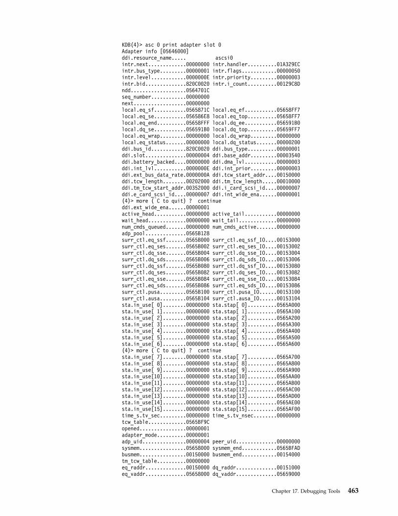
KDB(4)> asc 0 print adapter slot 0Adapter info [05646000]ddi.resource_name..... ascsi0intr.next.............00000000 intr.handler..........01A329ECintr.bus_type.........00000001 intr.flags............00000050intr.level............0000000E intr.priority.........00000003intr.bid..............820C0020 intr.i_count..........00129C8Dndd...................0564701Cseq_number............00000000next..................00000000local.eq_sf...........0565871C local.eq_ef...........05658FF7local.eq_se...........056586E8 local.eq_top..........05658FF7local.eq_end..........05658FFF local.dq_ee...........056591B0local.dq_se...........056591B0 local.dq_top..........05659FF7local.eq_wrap.........00000000 local.dq_wrap.........00000000local.eq_status.......00000000 local.dq_status.......00000200ddi.bus_id............820C0020 ddi.bus_type..........00000001ddi.slot..............00000004 ddi.base_addr.........00003540ddi.battery_backed....00000000 ddi.dma_lvl...........00000003ddi.int_lvl...........0000000E ddi.int_prior.........00000003ddi.ext_bus_data_rate.0000000A ddi.tcw_start_addr....00150000ddi.tcw_length........00202000 ddi.tm_tcw_length.....00010000ddi.tm_tcw_start_addr.00352000 ddi.i_card_scsi_id....00000007ddi.e_card_scsi_id....00000007 ddi.int_wide_ena......00000001(4)> more (|C to quit) ? continueddi.ext_wide_ena......00000001active_head...........00000000 active_tail...........00000000wait_head.............00000000 wait_tail.............00000000num_cmds_queued.......00000000 num_cmds_active.......00000000adp_pool..............0565B128surr_ctl.eq_ssf.......0565B000 surr_ctl.eq_ssf_IO....00153000surr_ctl.eq_ses.......0565B002 surr_ctl.eq_ses_IO....00153002surr_ctl.dq_sse.......0565B004 surr_ctl.dq_sse_IO....00153004surr_ctl.dq_sds.......0565B006 surr_ctl.dq_sds_IO....00153006surr_ctl.dq_ssf.......0565B080 surr_ctl.dq_ssf_IO....00153080surr_ctl.dq_ses.......0565B082 surr_ctl.dq_ses_IO....00153082surr_ctl.eq_sse.......0565B084 surr_ctl.eq_sse_IO....00153084surr_ctl.eq_sds.......0565B086 surr_ctl.eq_sds_IO....00153086surr_ctl.pusa.........0565B100 surr_ctl.pusa_IO......00153100surr_ctl.ausa.........0565B104 surr_ctl.ausa_IO......00153104sta.in_use[ 0]........00000000 sta.stap[ 0]..........0565A000sta.in_use[ 1]........00000000 sta.stap[ 1]..........0565A100sta.in_use[ 2]........00000000 sta.stap[ 2]..........0565A200sta.in_use[ 3]........00000000 sta.stap[ 3]..........0565A300sta.in_use[ 4]........00000000 sta.stap[ 4]..........0565A400sta.in_use[ 5]........00000000 sta.stap[ 5]..........0565A500sta.in_use[ 6]........00000000 sta.stap[ 6]..........0565A600(4)> more (|C to quit) ? continuesta.in_use[ 7]........00000000 sta.stap[ 7]..........0565A700sta.in_use[ 8]........00000000 sta.stap[ 8]..........0565A800sta.in_use[ 9]........00000000 sta.stap[ 9]..........0565A900sta.in_use[10]........00000000 sta.stap[10]..........0565AA00sta.in_use[11]........00000000 sta.stap[11]..........0565AB00sta.in_use[12]........00000000 sta.stap[12]..........0565AC00sta.in_use[13]........00000000 sta.stap[13]..........0565AD00sta.in_use[14]........00000000 sta.stap[14]..........0565AE00sta.in_use[15]........00000000 sta.stap[15]..........0565AF00time_s.tv_sec.........00000000 time_s.tv_nsec........00000000tcw_table.............0565BF9Copened................00000001adapter_mode..........00000001adp_uid...............00000004 peer_uid..............00000000sysmem................05658000 sysmem_end............0565BFADbusmem................00150000 busmem_end............00154000tm_tcw_table..........00000000eq_raddr..............00150000 dq_raddr..............00151000eq_vaddr..............05658000 dq_vaddr..............05659000
Chapter 17. Debugging Tools 463

sta_raddr.............00152000 sta_vaddr.............0565A000bufs..................00154000tm_sysmem.............00000000(4)> more (|C to quit) ? continuewdog.dog.next.........05646360 wdog.dog.prev.........0009A5C4wdog.dog.func.........01A32B28 wdog.dog.count........00000000wdog.dog.restart......0000001E wdog.ap...............05646000wdog.reason...........00000004tm.dog.next...........05647344 tm.dog.prev...........05646344tm.dog.func...........01A32B28 tm.dog.count..........00000000tm.dog.restart........00000000 tm.ap.................05646000tm.reason.............00000004delay_trb.to_next.....00000000 delay_trb.knext.......00000000delay_trb.kprev.......00000000 delay_trb.id..........00000000delay_trb.cpunum......00000000 delay_trb.flags.......00000000delay_trb.timerid.....00000000 delay_trb.eventlist...00000000delay_trb.timeout.it_interval.tv_sec....00000000 tv_nsec...00000000delay_trb.timeout.it_value.tv_sec.......00000000 tv_nsec...00000000delay_trb.func........00000000 delay_trb.func_data...00000000delay_trb.ipri........00000000 delay_trb.tof.........00000000xmem.aspace_id........FFFFFFFF xmem.xm_flag..........FFFFFFFFxmem.xm_version.......FFFFFFFF dma_channel...........10001000mtu...................00141000 num_tcw_words.........00000011shift.................0000001C tcw_word..............00000002resvd1................00000000 cfg_close.............00000000vpd_close.............00000000 locate_state..........00000004(4)> more (|C to quit) ? continuelocate_event..........FFFFFFFF rir_event.............FFFFFFFFvpd_event.............FFFFFFFF eid_event.............FFFFFFFFebp_event.............FFFFFFFF eid_lock..............FFFFFFFFrecv_fn...............01A3C54C tm_recv_fn............00000000tm_buf_info...........00000000 tm_head...............00000000tm_tail...............00000000 tm_recv_buf...........00000000tm_bufs_tot...........00000000 tm_bufs_at_adp........00000000tm_buf................00000000 tm_raddr..............00000000proto_tag_e...........0565D000 proto_tag_i...........00000000adapter_check.........00000000 [email protected]_start_time......00000000 [email protected][email protected] pipe_full_cnt.........00000000dump_state............00000000 pad...................00000000adp_cmd_pending.......00000000 reset_pending.........00000000epow_state............00000000 mm_reset_in_prog......00000000sleep_pending.........00000000 bus_reset_in_prog.....00000000first_try.............00000001 devs_in_use_I.........00000000devs_in_use_E.........00000002 num_buf_cmds..........00000000next_id...............000000D4 next_id_tm............00000000resvd4................00000000 ebp_flag..............00000000tm_bufs_blocked.......00000000 tm_enable_threshold...00000000limbo.................00000000
vscsi SubcommandThe vscsi subcommand prints virtual scsi information.
ExampleKDB(4)> lke 84 print kernel extension information
ADDRESS FILE FILESIZE FLAGS MODULE NAME84 05630780 01A36C00 00005A04 00000262 /etc/drivers/vscsiddpin
le_flags........ TEXT DATAINTEXT DATA DATAEXISTSle_fp........... 00000000le_loadcount.... 00000000le_usecount..... 00000001le_data/le_tid.. 01A3C3A0 <—- address (adjusted to 0xC468) neededle_datasize..... 00000264 to initialize the vscsi command.le_exports...... 0565E000le_lex.......... 00000000
464 Kernel Extensions and Device Support Programming Concepts
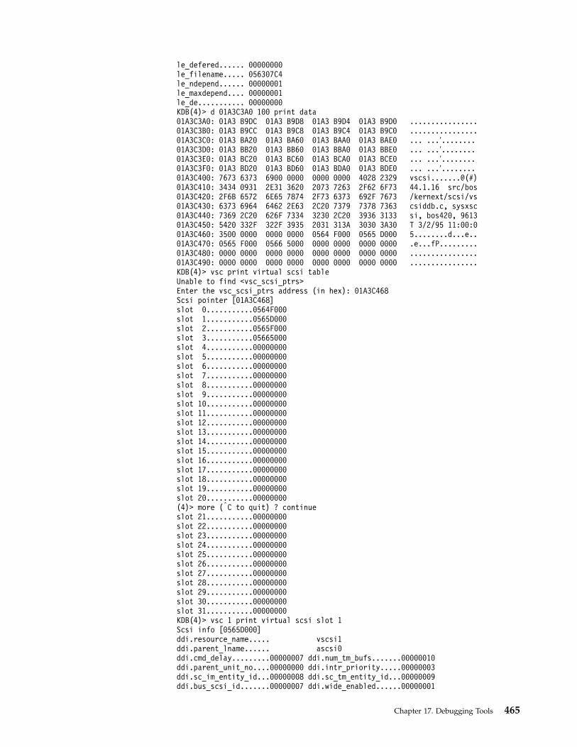
le_defered...... 00000000le_filename..... 056307C4le_ndepend...... 00000001le_maxdepend.... 00000001le_de........... 00000000KDB(4)> d 01A3C3A0 100 print data01A3C3A0: 01A3 B9DC 01A3 B9D8 01A3 B9D4 01A3 B9D0 ................01A3C3B0: 01A3 B9CC 01A3 B9C8 01A3 B9C4 01A3 B9C0 ................01A3C3C0: 01A3 BA20 01A3 BA60 01A3 BAA0 01A3 BAE0 ... ...′........01A3C3D0: 01A3 BB20 01A3 BB60 01A3 BBA0 01A3 BBE0 ... ...′........01A3C3E0: 01A3 BC20 01A3 BC60 01A3 BCA0 01A3 BCE0 ... ...′........01A3C3F0: 01A3 BD20 01A3 BD60 01A3 BDA0 01A3 BDE0 ... ...′........01A3C400: 7673 6373 6900 0000 0000 0000 4028 2329 vscsi.......@(#)01A3C410: 3434 0931 2E31 3620 2073 7263 2F62 6F73 44.1.16 src/bos01A3C420: 2F6B 6572 6E65 7874 2F73 6373 692F 7673 /kernext/scsi/vs01A3C430: 6373 6964 6462 2E63 2C20 7379 7378 7363 csiddb.c, sysxsc01A3C440: 7369 2C20 626F 7334 3230 2C20 3936 3133 si, bos420, 961301A3C450: 5420 332F 322F 3935 2031 313A 3030 3A30 T 3/2/95 11:00:001A3C460: 3500 0000 0000 0000 0564 F000 0565 D000 5........d...e..01A3C470: 0565 F000 0566 5000 0000 0000 0000 0000 .e...fP.........01A3C480: 0000 0000 0000 0000 0000 0000 0000 0000 ................01A3C490: 0000 0000 0000 0000 0000 0000 0000 0000 ................KDB(4)> vsc print virtual scsi tableUnable to find <vsc_scsi_ptrs>Enter the vsc_scsi_ptrs address (in hex): 01A3C468Scsi pointer [01A3C468]slot 0...........0564F000slot 1...........0565D000slot 2...........0565F000slot 3...........05665000slot 4...........00000000slot 5...........00000000slot 6...........00000000slot 7...........00000000slot 8...........00000000slot 9...........00000000slot 10...........00000000slot 11...........00000000slot 12...........00000000slot 13...........00000000slot 14...........00000000slot 15...........00000000slot 16...........00000000slot 17...........00000000slot 18...........00000000slot 19...........00000000slot 20...........00000000(4)> more (|C to quit) ? continueslot 21...........00000000slot 22...........00000000slot 23...........00000000slot 24...........00000000slot 25...........00000000slot 26...........00000000slot 27...........00000000slot 28...........00000000slot 29...........00000000slot 30...........00000000slot 31...........00000000KDB(4)> vsc 1 print virtual scsi slot 1Scsi info [0565D000]ddi.resource_name..... vscsi1ddi.parent_lname...... ascsi0ddi.cmd_delay.........00000007 ddi.num_tm_bufs.......00000010ddi.parent_unit_no....00000000 ddi.intr_priority.....00000003ddi.sc_im_entity_id...00000008 ddi.sc_tm_entity_id...00000009ddi.bus_scsi_id.......00000007 ddi.wide_enabled......00000001
Chapter 17. Debugging Tools 465

ddi.location..........00000001 ddi.num_cmd_elems.....00000028cdar_wdog.dog.next....0C3AB264 cdar_wdog.dog.prev....0009AE64cdar_wdog.dog.func....01A3C534 cdar_wdog.dog.count...00000000cdar_wdog.dog.restart.00000007 cdar_wdog.scsi........0565D000cdar_wdog.index.......00000000 cdar_wdog.timer_id....00000001cdar_wdog.save_time...00000000reset_wdog.dog.next...0C50F000 reset_wdog.dog.prev...0009AB84reset_wdog.dog.func...01A3C534 reset_wdog.dog.count..00000000reset_wdog.dog.restart00000008 reset_wdog.scsi.......0565D000reset_wdog.index......00000000 reset_wdog.timer_id...00000004reset_wdog.save_time..00000000RESET_CMD_ELEM.REPLY.header.format.........00000000 header.length.........00000000header.options........00000000 header.reserved.......00000000header.src_unit.......00000000 header.src_entity.....00000000header.dest_unit......00000000 header.dest_entity....00000000(4)> more (|C to quit) ? continueheader.correlation_id.00000000 adap_status...........00000000resid_count...........00000000 resid_addr............00000000cmd_status............00000000 scsi_status...........00000000cmd_error_code........00000000 device_error_code.....00000000RESET_CMD_ELEM.CTL_ELEMnext..................00000000 prev..................00000000flags.................00000003 key...................00000000status................00000000 num_pd_info...........00000000pds_data_len..........00000000 reply_elem............0565D07Creply_elem_len........0000002C ctl_elem..............0565D0D4pd_info...............00000000RESET_CMD_ELEM.REQUEST.header.format.........00000000 header.length.........00000054header.options........00000046 header.reserved.......00000000header.src_unit.......00000000 header.src_entity.....00000000header.dest_unit......00000000 header.dest_entity....00000000header.correlation_id.0565D0A8 type2_pd.desc_number..00000000type2_pd.ctl_info.....00008280 type2_pd.word1........00000001type2_pd.word2........00000000 type2_pd.word3........00000000type1_pd.desc_number..00000000 type1_pd.ctl_info.....00000180type1_pd.word1........00000054 type1_pd.word2........00000000type1_pd.word3........00000000 scsi_cdb.next_addr1...00000000(4)> more (|C to quit) ? continuescsi_cdb.next_addr2...00000000 scsi_cdb.scsi_id......00000000scsi_cdb.scsi_lun.....00000000 scsi_cdb.media_flags..0000C400RESET_CMD_ELEM.REQUEST.SCSI_CDB.scsi_cmd_blk.scsi_op_code..00000000 scsi_cmd_blk.lun...........00000000scsi_cmd_blk.scsi_bytes@...0565D116 scsi_extra.................00000000scsi_data_length...........00000000RESET_CMD_ELEM.PD_INFO1.next..................00000000 buf_type..............00000000pd_ctl_info...........00000000 mapped_addr...........00000000total_len.............00000000 num_tcws..............00000000p_buf_list............00000000RESET_CMD_ELEM.bp....................00000000 scsi..................0565D000cmd_type..............00000004 cmd_state.............00000000preempt...............00000000 tag...................00000000status_filter.type....00000129 status_filter.mask....0565D001status_filter.sid.....00000000scsi_lock.............FFFFFFFF ioctl_lock............E801AD40devno.................00110001 open_event............00000000ioctl_event...........FFFFFFFF [email protected] [email protected](4)> more (|C to quit) ? [email protected] head_free.............00000000b_pool................00000000 read_bufs.............00000000cmd_pool..............0C6CC000 next..................00000000head_gw_free..........00000000 tail_gw_free..........00000000proc_results..........00000000 proc_sleep_id.........00000000
466 Kernel Extensions and Device Support Programming Concepts
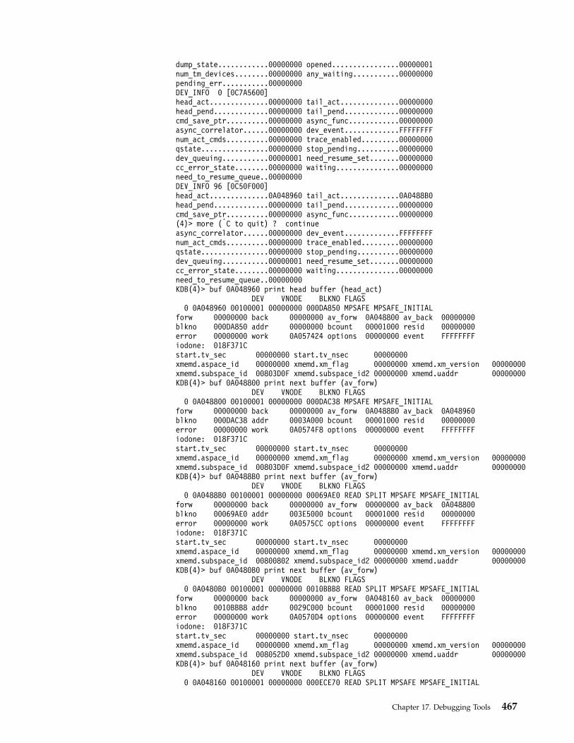
dump_state............00000000 opened................00000001num_tm_devices........00000000 any_waiting...........00000000pending_err...........00000000DEV_INFO 0 [0C7A5600]head_act..............00000000 tail_act..............00000000head_pend.............00000000 tail_pend.............00000000cmd_save_ptr..........00000000 async_func............00000000async_correlator......00000000 dev_event.............FFFFFFFFnum_act_cmds..........00000000 trace_enabled.........00000000qstate................00000000 stop_pending..........00000000dev_queuing...........00000001 need_resume_set.......00000000cc_error_state........00000000 waiting...............00000000need_to_resume_queue..00000000DEV_INFO 96 [0C50F000]head_act..............0A048960 tail_act..............0A0488B0head_pend.............00000000 tail_pend.............00000000cmd_save_ptr..........00000000 async_func............00000000(4)> more (|C to quit) ? continueasync_correlator......00000000 dev_event.............FFFFFFFFnum_act_cmds..........00000000 trace_enabled.........00000000qstate................00000000 stop_pending..........00000000dev_queuing...........00000001 need_resume_set.......00000000cc_error_state........00000000 waiting...............00000000need_to_resume_queue..00000000KDB(4)> buf 0A048960 print head buffer (head_act)
DEV VNODE BLKNO FLAGS0 0A048960 00100001 00000000 000DA850 MPSAFE MPSAFE_INITIAL
forw 00000000 back 00000000 av_forw 0A048800 av_back 00000000blkno 000DA850 addr 00000000 bcount 00001000 resid 00000000error 00000000 work 0A057424 options 00000000 event FFFFFFFFiodone: 018F371Cstart.tv_sec 00000000 start.tv_nsec 00000000xmemd.aspace_id 00000000 xmemd.xm_flag 00000000 xmemd.xm_version 00000000xmemd.subspace_id 00803D0F xmemd.subspace_id2 00000000 xmemd.uaddr 00000000KDB(4)> buf 0A048800 print next buffer (av_forw)
DEV VNODE BLKNO FLAGS0 0A048800 00100001 00000000 000DAC38 MPSAFE MPSAFE_INITIAL
forw 00000000 back 00000000 av_forw 0A0488B0 av_back 0A048960blkno 000DAC38 addr 0003A000 bcount 00001000 resid 00000000error 00000000 work 0A0574F8 options 00000000 event FFFFFFFFiodone: 018F371Cstart.tv_sec 00000000 start.tv_nsec 00000000xmemd.aspace_id 00000000 xmemd.xm_flag 00000000 xmemd.xm_version 00000000xmemd.subspace_id 00803D0F xmemd.subspace_id2 00000000 xmemd.uaddr 00000000KDB(4)> buf 0A0488B0 print next buffer (av_forw)
DEV VNODE BLKNO FLAGS0 0A0488B0 00100001 00000000 00069AE0 READ SPLIT MPSAFE MPSAFE_INITIAL
forw 00000000 back 00000000 av_forw 00000000 av_back 0A048800blkno 00069AE0 addr 003E5000 bcount 00001000 resid 00000000error 00000000 work 0A0575CC options 00000000 event FFFFFFFFiodone: 018F371Cstart.tv_sec 00000000 start.tv_nsec 00000000xmemd.aspace_id 00000000 xmemd.xm_flag 00000000 xmemd.xm_version 00000000xmemd.subspace_id 00800802 xmemd.subspace_id2 00000000 xmemd.uaddr 00000000KDB(4)> buf 0A0480B0 print next buffer (av_forw)
DEV VNODE BLKNO FLAGS0 0A0480B0 00100001 00000000 0010BBB8 READ SPLIT MPSAFE MPSAFE_INITIAL
forw 00000000 back 00000000 av_forw 0A048160 av_back 00000000blkno 0010BBB8 addr 0029C000 bcount 00001000 resid 00000000error 00000000 work 0A0570D4 options 00000000 event FFFFFFFFiodone: 018F371Cstart.tv_sec 00000000 start.tv_nsec 00000000xmemd.aspace_id 00000000 xmemd.xm_flag 00000000 xmemd.xm_version 00000000xmemd.subspace_id 008052D0 xmemd.subspace_id2 00000000 xmemd.uaddr 00000000KDB(4)> buf 0A048160 print next buffer (av_forw)
DEV VNODE BLKNO FLAGS0 0A048160 00100001 00000000 000ECE70 READ SPLIT MPSAFE MPSAFE_INITIAL
Chapter 17. Debugging Tools 467
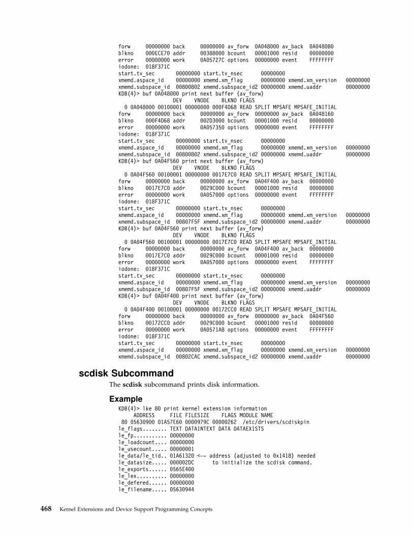
forw 00000000 back 00000000 av_forw 0A048000 av_back 0A0480B0blkno 000ECE70 addr 00388000 bcount 00001000 resid 00000000error 00000000 work 0A05727C options 00000000 event FFFFFFFFiodone: 018F371Cstart.tv_sec 00000000 start.tv_nsec 00000000xmemd.aspace_id 00000000 xmemd.xm_flag 00000000 xmemd.xm_version 00000000xmemd.subspace_id 00800802 xmemd.subspace_id2 00000000 xmemd.uaddr 00000000KDB(4)> buf 0A048000 print next buffer (av_forw)
DEV VNODE BLKNO FLAGS0 0A048000 00100001 00000000 000F4D68 READ SPLIT MPSAFE MPSAFE_INITIAL
forw 00000000 back 00000000 av_forw 00000000 av_back 0A048160blkno 000F4D68 addr 002D3000 bcount 00001000 resid 00000000error 00000000 work 0A057350 options 00000000 event FFFFFFFFiodone: 018F371Cstart.tv_sec 00000000 start.tv_nsec 00000000xmemd.aspace_id 00000000 xmemd.xm_flag 00000000 xmemd.xm_version 00000000xmemd.subspace_id 00800802 xmemd.subspace_id2 00000000 xmemd.uaddr 00000000KDB(4)> buf 0A04F560 print next buffer (av_forw)
DEV VNODE BLKNO FLAGS0 0A04F560 00100001 00000000 0017E7C0 READ SPLIT MPSAFE MPSAFE_INITIAL
forw 00000000 back 00000000 av_forw 0A04F400 av_back 00000000blkno 0017E7C0 addr 0029C000 bcount 00001000 resid 00000000error 00000000 work 0A057000 options 00000000 event FFFFFFFFiodone: 018F371Cstart.tv_sec 00000000 start.tv_nsec 00000000xmemd.aspace_id 00000000 xmemd.xm_flag 00000000 xmemd.xm_version 00000000xmemd.subspace_id 00807F5F xmemd.subspace_id2 00000000 xmemd.uaddr 00000000KDB(4)> buf 0A04F560 print next buffer (av_forw)
DEV VNODE BLKNO FLAGS0 0A04F560 00100001 00000000 0017E7C0 READ SPLIT MPSAFE MPSAFE_INITIAL
forw 00000000 back 00000000 av_forw 0A04F400 av_back 00000000blkno 0017E7C0 addr 0029C000 bcount 00001000 resid 00000000error 00000000 work 0A057000 options 00000000 event FFFFFFFFiodone: 018F371Cstart.tv_sec 00000000 start.tv_nsec 00000000xmemd.aspace_id 00000000 xmemd.xm_flag 00000000 xmemd.xm_version 00000000xmemd.subspace_id 00807F5F xmemd.subspace_id2 00000000 xmemd.uaddr 00000000KDB(4)> buf 0A04F400 print next buffer (av_forw)
DEV VNODE BLKNO FLAGS0 0A04F400 00100001 00000000 00172CC0 READ SPLIT MPSAFE MPSAFE_INITIAL
forw 00000000 back 00000000 av_forw 00000000 av_back 0A04F560blkno 00172CC0 addr 0029C000 bcount 00001000 resid 00000000error 00000000 work 0A0571A8 options 00000000 event FFFFFFFFiodone: 018F371Cstart.tv_sec 00000000 start.tv_nsec 00000000xmemd.aspace_id 00000000 xmemd.xm_flag 00000000 xmemd.xm_version 00000000xmemd.subspace_id 00802CAC xmemd.subspace_id2 00000000 xmemd.uaddr 00000000
scdisk SubcommandThe scdisk subcommand prints disk information.
ExampleKDB(4)> lke 80 print kernel extension information
ADDRESS FILE FILESIZE FLAGS MODULE NAME80 05630900 01A57E60 0000979C 00000262 /etc/drivers/scdiskpin
le_flags........ TEXT DATAINTEXT DATA DATAEXISTSle_fp........... 00000000le_loadcount.... 00000000le_usecount..... 00000001le_data/le_tid.. 01A61320 <—- address (adjusted to 0x1418) neededle_datasize..... 000002DC to initialize the scdisk command.le_exports...... 0565E400le_lex.......... 00000000le_defered...... 00000000le_filename..... 05630944
468 Kernel Extensions and Device Support Programming Concepts

le_ndepend...... 00000001le_maxdepend.... 00000001le_de........... 00000000KDB(4)> d 01A61320 100 print data01A61320: 0000 000B 0000 0006 FFFF FFFF 0562 7C00 .............b|.01A61330: 0000 0000 0000 0000 0000 0000 0000 0000 ................01A61340: 01A6 08DC 01A6 08D8 01A6 08D4 01A6 08D0 ................01A61350: 01A6 08CC 01A6 08C8 01A6 08C4 01A6 08C0 ................01A61360: 01A6 0920 01A6 0960 01A6 09A0 01A6 09E0 ... ...′........01A61370: 01A6 0A20 01A6 0A60 01A6 0AA0 01A6 0AE0 ... ...′........01A61380: 01A6 0B20 01A6 0B60 01A6 0BA0 01A6 0BE0 ... ...′........01A61390: 01A6 0C20 01A6 0C60 01A6 0CA0 01A6 0CE0 ... ...′........01A613A0: 7363 696E 666F 0000 6366 676C 6973 7400 scinfo..cfglist.01A613B0: 6F70 6C69 7374 0000 4028 2329 3435 2020 oplist..@(#)4501A613C0: 312E 3139 2E36 2E31 3620 2073 7263 2F62 1.19.6.16 src/b01A613D0: 6F73 2F6B 6572 6E65 7874 2F64 6973 6B2F os/kernext/disk/01A613E0: 7363 6469 736B 622E 632C 2073 7973 7864 scdiskb.c, sysxd01A613F0: 6973 6B2C 2062 6F73 3432 302C 2039 3631 isk, bos420, 96101A61400: 3354 2031 2F38 2F39 3620 3233 3A34 313A 3T 1/8/96 23:41:01A61410: 3538 0000 0000 0000 0567 4000 0567 5000 [email protected](4)> scd print scsi disk tableUnable to find <scdisk_list>Enter the scdisk_list address (in hex): 01A61418Scsi pointer [01A61418]slot 0...........05674000slot 1...........05675000slot 2...........0566C000slot 3...........0566D000slot 4...........0566E000slot 5...........0566F000slot 6...........05670000slot 7...........05671000slot 8...........05672000slot 9...........05673000slot 10...........0C40D000slot 11...........00000000slot 12...........00000000slot 13...........00000000slot 14...........00000000slot 15...........00000000KDB(4)> scd 0 print scsi disk slot 0Scdisk info [05674000]next......................00000000 next_open.................00000000devno.....................00120000 adapter_devno.............00100000watchdog_timer.watch.@....05674010 watchdog_timer.pointer....05674000scsi_id...................00000000 lun_id....................00000000reset_count...............00000000 dk_cmd_q_head.............00000000dk_cmd_q_tail.............00000000 [email protected]_pool..................05628400 pool_index................00000000open_event................FFFFFFFF checked_cmd...............00000000writev_err_cmd............00000000 reassign_err_cmd..........00000000reset_cmd@................056740FC [email protected][email protected] [email protected][email protected] [email protected][email protected] mode......................00000001disk_intrpt...............00000000 raw_io_intrpt.............00000000ioctl_chg_mode_flg........00000000 m_sense_status............00000000opened....................00000001 cmd_pending...............00000000errno.....................00000000 retain_reservation........00000000q_type....................00000000 q_err_value...............00000001clr_q_on_error............00000001 buffer_ratio..............00000000cmd_tag_q.................00000000 q_status..................00000000q_clr.....................00000000 timer_status..............00000000restart_unit..............00000000 retry_flag................00000000(4)> more (|C to quit) ? continuesafe_relocate.............00000000 async_flag................00000000dump_inited...............00000001 extended_rw...............00000001
Chapter 17. Debugging Tools 469

reset_delay...............00000002 starting_close............00000000reset_failures............00000000 wprotected................00000000reserve_lock..............00000001 prevent_eject.............00000000cfg_prevent_ej............00000000 cfg_reserve_lck...........00000001load_eject_alt............00000000 pm_susp_bdr...............00000000dev_type..................00000001 ioctl_pending.............00000000play_audio................00000000 overide_pg_e..............00000000cd_mode1_code.............00000000 cd_mode2_form1_code.......00000000cd_mode2_form2_code.......00000000 cd_da_code................00000000current_cd_code...........00000000 current_cd_mode...........00000001multi_session.............00000000 valid_cd_modes............00000000mult_of_blksize...........00000001 play_audio_started........00000000rw_timeout................0000001E fmt_timeout...............00000000start_timeout.............0000003C reassign_timeout..........00000078queue_depth...............00000001 cmds_out..................00000000raw_io_cmd................00000000 currbuf...................0A0546E0low.......................0A14E3C0 block_size................00000200cfg_block_size............00000200 last_ses_pvd_lba..........00000000max_request...............00040000 max_coalesce..............00010000lock......................FFFFFFFF fp........................00414348(4)> more (|C to quit) ? [email protected] [email protected]_data_length..........0000003D [email protected][email protected] [email protected][email protected] [email protected][email protected] [email protected][email protected] [email protected]@.......................05674BB4 [email protected]@.......................05674C44 [email protected]@.................05674CA4 [email protected]@[email protected] spin_lock.................E80039A0pmh@......................05674CFC pm_pending................00000000pm_reserve@...............05674D41 pm_device_id..............00100000pm_event..................FFFFFFFF [email protected](4)> file 00414348 print file (fp)
COUNT OFFSET DATA TYPE FLAGS18 file+000330 1 0000000000000000 0BC4A950 GNODE WRITE
f_flag......... 00000002 f_count........ 00000001f_msgcount......... 0000 f_type............. 0003f_data......... 0BC4A950 f_offset... 0000000000000000f_dir_off...... 00000000 f_cred......... 00000000f_lock@........ 00414368 f_lock......... E88007C0f_offset_lock@. 0041436C f_offset_lock.. E88007E0f_vinfo........ 00000000 f_ops.......... 001F3CD0 gno_fops+000000GNODE.......... 0BC4A950gn_seg....... 007FFFFF gn_mwrcnt.... 00000000 gn_mrdcnt.... 00000000gn_rdcnt..... 00000000 gn_wrcnt..... 00000002 gn_excnt..... 00000000gn_rshcnt.... 00000000 gn_ops....... 00000000 gn_vnode..... 00000000gn_reclk..... 00000000 gn_rdev...... 00100000gn_chan...... 00000000 gn_filocks... 00000000 gn_data...... 0BC4A940gn_type...... BLK gn_flags.....KDB(4)> buf 0A0546E0 print current buffer (currbuf)
DEV VNODE BLKNO FLAGS0 0A0546E0 00120000 00000000 00070A58 READ SPLIT MPSAFE MPSAFE_INITIAL
forw 00000000 back 00000000 av_forw 0A05DC60 av_back 0A14E3C0blkno 00070A58 addr 00626000 bcount 00001000 resid 00000000error 00000000 work 00000000 options 00000000 event FFFFFFFFiodone: 019057D4start.tv_sec 00000000 start.tv_nsec 00000000xmemd.aspace_id 00000000 xmemd.xm_flag 00000000 xmemd.xm_version 00000000xmemd.subspace_id 00800802 xmemd.subspace_id2 00000000 xmemd.uaddr 00000000
470 Kernel Extensions and Device Support Programming Concepts
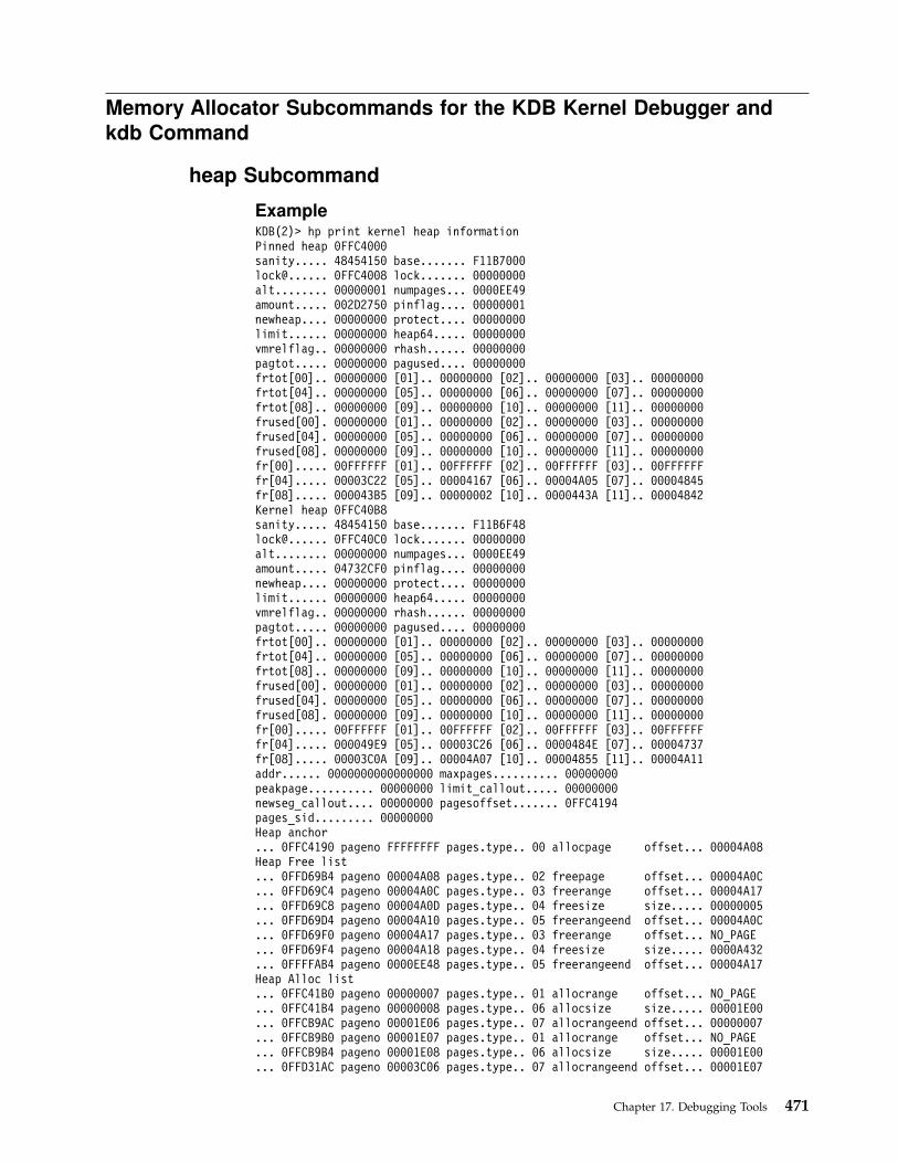
Memory Allocator Subcommands for the KDB Kernel Debugger and
kdb Command
heap Subcommand
ExampleKDB(2)> hp print kernel heap informationPinned heap 0FFC4000sanity..... 48454150 base....... F11B7000lock@...... 0FFC4008 lock....... 00000000alt........ 00000001 numpages... 0000EE49amount..... 002D2750 pinflag.... 00000001newheap.... 00000000 protect.... 00000000limit...... 00000000 heap64..... 00000000vmrelflag.. 00000000 rhash...... 00000000pagtot..... 00000000 pagused.... 00000000frtot[00].. 00000000 [01].. 00000000 [02].. 00000000 [03].. 00000000frtot[04].. 00000000 [05].. 00000000 [06].. 00000000 [07].. 00000000frtot[08].. 00000000 [09].. 00000000 [10].. 00000000 [11].. 00000000frused[00]. 00000000 [01].. 00000000 [02].. 00000000 [03].. 00000000frused[04]. 00000000 [05].. 00000000 [06].. 00000000 [07].. 00000000frused[08]. 00000000 [09].. 00000000 [10].. 00000000 [11].. 00000000fr[00]..... 00FFFFFF [01].. 00FFFFFF [02].. 00FFFFFF [03].. 00FFFFFFfr[04]..... 00003C22 [05].. 00004167 [06].. 00004A05 [07].. 00004845fr[08]..... 000043B5 [09].. 00000002 [10].. 0000443A [11].. 00004842Kernel heap 0FFC40B8sanity..... 48454150 base....... F11B6F48lock@...... 0FFC40C0 lock....... 00000000alt........ 00000000 numpages... 0000EE49amount..... 04732CF0 pinflag.... 00000000newheap.... 00000000 protect.... 00000000limit...... 00000000 heap64..... 00000000vmrelflag.. 00000000 rhash...... 00000000pagtot..... 00000000 pagused.... 00000000frtot[00].. 00000000 [01].. 00000000 [02].. 00000000 [03].. 00000000frtot[04].. 00000000 [05].. 00000000 [06].. 00000000 [07].. 00000000frtot[08].. 00000000 [09].. 00000000 [10].. 00000000 [11].. 00000000frused[00]. 00000000 [01].. 00000000 [02].. 00000000 [03].. 00000000frused[04]. 00000000 [05].. 00000000 [06].. 00000000 [07].. 00000000frused[08]. 00000000 [09].. 00000000 [10].. 00000000 [11].. 00000000fr[00]..... 00FFFFFF [01].. 00FFFFFF [02].. 00FFFFFF [03].. 00FFFFFFfr[04]..... 000049E9 [05].. 00003C26 [06].. 0000484E [07].. 00004737fr[08]..... 00003C0A [09].. 00004A07 [10].. 00004855 [11].. 00004A11addr...... 0000000000000000 maxpages.......... 00000000peakpage.......... 00000000 limit_callout..... 00000000newseg_callout.... 00000000 pagesoffset....... 0FFC4194pages_sid......... 00000000Heap anchor... 0FFC4190 pageno FFFFFFFF pages.type.. 00 allocpage offset... 00004A08Heap Free list... 0FFD69B4 pageno 00004A08 pages.type.. 02 freepage offset... 00004A0C... 0FFD69C4 pageno 00004A0C pages.type.. 03 freerange offset... 00004A17... 0FFD69C8 pageno 00004A0D pages.type.. 04 freesize size..... 00000005... 0FFD69D4 pageno 00004A10 pages.type.. 05 freerangeend offset... 00004A0C... 0FFD69F0 pageno 00004A17 pages.type.. 03 freerange offset... NO_PAGE... 0FFD69F4 pageno 00004A18 pages.type.. 04 freesize size..... 0000A432... 0FFFFAB4 pageno 0000EE48 pages.type.. 05 freerangeend offset... 00004A17Heap Alloc list... 0FFC41B0 pageno 00000007 pages.type.. 01 allocrange offset... NO_PAGE... 0FFC41B4 pageno 00000008 pages.type.. 06 allocsize size..... 00001E00... 0FFCB9AC pageno 00001E06 pages.type.. 07 allocrangeend offset... 00000007... 0FFCB9B0 pageno 00001E07 pages.type.. 01 allocrange offset... NO_PAGE... 0FFCB9B4 pageno 00001E08 pages.type.. 06 allocsize size..... 00001E00... 0FFD31AC pageno 00003C06 pages.type.. 07 allocrangeend offset... 00001E07
Chapter 17. Debugging Tools 471
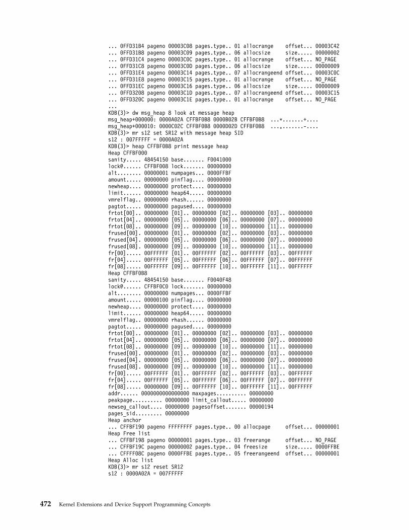
... 0FFD31B4 pageno 00003C08 pages.type.. 01 allocrange offset... 00003C42
... 0FFD31B8 pageno 00003C09 pages.type.. 06 allocsize size..... 00000002
... 0FFD31C4 pageno 00003C0C pages.type.. 01 allocrange offset... NO_PAGE
... 0FFD31C8 pageno 00003C0D pages.type.. 06 allocsize size..... 00000009
... 0FFD31E4 pageno 00003C14 pages.type.. 07 allocrangeend offset... 00003C0C
... 0FFD31E8 pageno 00003C15 pages.type.. 01 allocrange offset... NO_PAGE
... 0FFD31EC pageno 00003C16 pages.type.. 06 allocsize size..... 00000009
... 0FFD3208 pageno 00003C1D pages.type.. 07 allocrangeend offset... 00003C15
... 0FFD320C pageno 00003C1E pages.type.. 01 allocrange offset... NO_PAGE
...KDB(3)> dw msg_heap 8 look at message heapmsg_heap+000000: 0000A02A CFFBF0B8 0000B02B CFFBF0B8 ...*.......+....msg_heap+000010: 0000C02C CFFBF0B8 0000D02D CFFBF0B8 ...,.......-....KDB(3)> mr s12 set SR12 with message heap SIDs12 : 007FFFFF = 0000A02AKDB(3)> heap CFFBF0B8 print message heapHeap CFFBF000sanity..... 48454150 base....... F0041000lock@...... CFFBF008 lock....... 00000000alt........ 00000001 numpages... 0000FFBFamount..... 00000000 pinflag.... 00000000newheap.... 00000000 protect.... 00000000limit...... 00000000 heap64..... 00000000vmrelflag.. 00000000 rhash...... 00000000pagtot..... 00000000 pagused.... 00000000frtot[00].. 00000000 [01].. 00000000 [02].. 00000000 [03].. 00000000frtot[04].. 00000000 [05].. 00000000 [06].. 00000000 [07].. 00000000frtot[08].. 00000000 [09].. 00000000 [10].. 00000000 [11].. 00000000frused[00]. 00000000 [01].. 00000000 [02].. 00000000 [03].. 00000000frused[04]. 00000000 [05].. 00000000 [06].. 00000000 [07].. 00000000frused[08]. 00000000 [09].. 00000000 [10].. 00000000 [11].. 00000000fr[00]..... 00FFFFFF [01].. 00FFFFFF [02].. 00FFFFFF [03].. 00FFFFFFfr[04]..... 00FFFFFF [05].. 00FFFFFF [06].. 00FFFFFF [07].. 00FFFFFFfr[08]..... 00FFFFFF [09].. 00FFFFFF [10].. 00FFFFFF [11].. 00FFFFFFHeap CFFBF0B8sanity..... 48454150 base....... F0040F48lock@...... CFFBF0C0 lock....... 00000000alt........ 00000000 numpages... 0000FFBFamount..... 00000100 pinflag.... 00000000newheap.... 00000000 protect.... 00000000limit...... 00000000 heap64..... 00000000vmrelflag.. 00000000 rhash...... 00000000pagtot..... 00000000 pagused.... 00000000frtot[00].. 00000000 [01].. 00000000 [02].. 00000000 [03].. 00000000frtot[04].. 00000000 [05].. 00000000 [06].. 00000000 [07].. 00000000frtot[08].. 00000000 [09].. 00000000 [10].. 00000000 [11].. 00000000frused[00]. 00000000 [01].. 00000000 [02].. 00000000 [03].. 00000000frused[04]. 00000000 [05].. 00000000 [06].. 00000000 [07].. 00000000frused[08]. 00000000 [09].. 00000000 [10].. 00000000 [11].. 00000000fr[00]..... 00FFFFFF [01].. 00FFFFFF [02].. 00FFFFFF [03].. 00FFFFFFfr[04]..... 00FFFFFF [05].. 00FFFFFF [06].. 00FFFFFF [07].. 00FFFFFFfr[08]..... 00000000 [09].. 00FFFFFF [10].. 00FFFFFF [11].. 00FFFFFFaddr...... 0000000000000000 maxpages.......... 00000000peakpage.......... 00000000 limit_callout..... 00000000newseg_callout.... 00000000 pagesoffset....... 00000194pages_sid......... 00000000Heap anchor... CFFBF190 pageno FFFFFFFF pages.type.. 00 allocpage offset... 00000001Heap Free list... CFFBF198 pageno 00000001 pages.type.. 03 freerange offset... NO_PAGE... CFFBF19C pageno 00000002 pages.type.. 04 freesize size..... 0000FFBE... CFFFF08C pageno 0000FFBE pages.type.. 05 freerangeend offset... 00000001Heap Alloc listKDB(3)> mr s12 reset SR12s12 : 0000A02A = 007FFFFF
472 Kernel Extensions and Device Support Programming Concepts
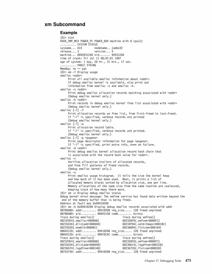
xm Subcommand
Example(0)> statRS6K_SMP_MCA POWER_PC POWER_604 machine with 8 cpu(s).......... SYSTEM STATUSsysname... AIX nodename.. jumbo32release... 3 version... 4machine... 00920312A0 nid....... 920312A0time of crash: Fri Jul 11 08:07:01 1997age of system: 1 day, 20 hr., 31 min., 17 sec........... PANIC STRINGMemdbg: *w == pat(0)> xm -? Display usagexmalloc <addr>
Print all available xmalloc information about <addr>.If debug xmalloc kernel is available, also print outinformation from xmalloc -s and xmalloc -h.
xmalloc -s <addr>Print debug xmalloc allocation records matching associated with <addr>(Debug xmalloc kernel only.)
xmalloc -h <addr>Print records in debug xmalloc kernel free list associated with <addr>(Debug xmalloc kernel only.)
xmalloc [-l] -fPrint allocation records on free list, from first-freed to last-freed.If "-l" is specified, verbose records are printed(Debug xmalloc kernel only.)
xmalloc [-l] -aPrint allocation record table.If "-l" is specified, verbose records are printed.(Debug xmalloc kernel only.)
xmalloc [-l] -p <pageno>Print page descriptor information for page <pageno>.If "-l" is specified, print extra info, even on failure.
xmalloc -d <addr>Print debug xmalloc kernel allocation record hash chain thatis associated with the record hash value for <addr>.
xmalloc -vVerifies allocation trailers of allocated records,and free fill patterns of freed records.(Debug xmalloc kernel only.)
xmalloc -uPrint xmalloc usage histogram. It tells the size the kernel heapand how much of it has been used. Next, it prints a list ofallocated memory blocks sorted by allocation size, one per line.Memory allocations of the same size from the same routine are coalesced,keeping track of how many there were.
(0)> xm -s Display debug xmalloc statusDebug kernel error message: The xmfree service has found data written beyond theend of the memory buffer that is being freed.Address at fault was 0x09410200(0)> xm -h 0x09410200 Display debug xmalloc records associated with addr0B78DAB0: addr......... 09410200 req_size..... 128 freed unpinned0B78DAB0: pid.......... 00043158 comm......... bcrossTrace during xmalloc() Trace during xmfree()002329E4(.xmalloc+0000A8) 002328F0(.xmfree+0000FC)00235CD4(.dlistadd+000040) 00234F04(.setbitmaps+0001BC)00235520(.newblk+00006C) 00236894(.finicom+0001A4)0B645120: addr......... 09410200 req_size..... 128 freed unpinned0B645120: pid.......... 0007DCAC comm......... bcrossTrace during xmalloc() Trace during xmfree()002329E4(.xmalloc+0000A8) 002328F0(.xmfree+0000FC)00235CD4(.dlistadd+000040) 00236614(.logdfree+0001E8)00236574(.logdfree+000148) 00236720(.finicom+000030)0B7A3750: addr......... 09410200 req_size..... 128 freed unpinned
Chapter 17. Debugging Tools 473

0B7A3750: pid.......... 000010BA comm......... syncdTrace during xmalloc() Trace during xmfree()002329E4(.xmalloc+0000A8) 002328F0(.xmfree+0000FC)00235CD4(.dlistadd+000040) 00234F04(.setbitmaps+0001BC)00235520(.newblk+00006C) 00236894(.finicom+0001A4)0B52B330: addr......... 09410200 req_size..... 128 freed unpinned0B52B330: pid.......... 00058702 comm......... bcrossTrace during xmalloc() Trace during xmfree()002329E4(.xmalloc+0000A8) 002328F0(.xmfree+0000FC)00235CD4(.dlistadd+000040) 00236698(.logdfree+00026C)00236510(.logdfree+0000E4) 00236720(.finicom+000030)07A33840: addr......... 09410200 req_size..... 133 freed unpinned07A33840: pid.......... 00042C24 comm......... kshTrace during xmalloc() Trace during xmfree()002329E4(.xmalloc+0000A8) 002328F0(.xmfree+0000FC)00271F28(.ld_pathopen+000160) 00271D24(.ld_pathclear+00008C)0027FB6C(.ld_getlib+000074) 002ABF04(.ld_execload+00075C)0B796480: addr......... 09410200 req_size..... 133 freed unpinned0B796480: pid.......... 0005C2E0 comm......... kshTrace during xmalloc() Trace during xmfree()002329E4(.xmalloc+0000A8) 002328F0(.xmfree+0000FC)00271F28(.ld_pathopen+000160) 00271D24(.ld_pathclear+00008C)0027FB6C(.ld_getlib+000074) 002ABF04(.ld_execload+00075C)07A31420: addr......... 09410200 req_size..... 135 freed unpinned07A31420: pid.......... 0007161A comm......... kshTrace during xmalloc() Trace during xmfree()002329E4(.xmalloc+0000A8) 002328F0(.xmfree+0000FC)00271F28(.ld_pathopen+000160) 00271D24(.ld_pathclear+00008C)0027FB6C(.ld_getlib+000074) 002ABF04(.ld_execload+00075C)07A38630: addr......... 09410200 req_size..... 125 freed unpinned07A38630: pid.......... 0001121E comm......... kshTrace during xmalloc() Trace during xmfree()002329E4(.xmalloc+0000A8) 002328F0(.xmfree+0000FC)00271F28(.ld_pathopen+000160) 00271D24(.ld_pathclear+00008C)0027FB6C(.ld_getlib+000074) 002ABF04(.ld_execload+00075C)07A3D240: addr......... 09410200 req_size..... 133 freed unpinned07A3D240: pid.......... 0000654C comm......... kshTrace during xmalloc() Trace during xmfree()002329E4(.xmalloc+0000A8) 002328F0(.xmfree+0000FC)00271F28(.ld_pathopen+000160) 00271D24(.ld_pathclear+00008C)0027FB6C(.ld_getlib+000074) 002ABF04(.ld_execload+00075C)
The xm subcommand can be used to find memory location of any heap record,knowing the page index (pageno) , or to find the heap record knowing theallocated memory location.
Example(0)> heap...Heap Alloc list... 0FFC41B0 pageno 00000007 pages.type.. 01 allocrange offset... NO_PAGE... 0FFC41B4 pageno 00000008 pages.type.. 06 allocsize size..... 00001E00... 0FFCB9AC pageno 00001E06 pages.type.. 07 allocrangeend offset... 00000007... 0FFCB9B0 pageno 00001E07 pages.type.. 01 allocrange offset... NO_PAGE... 0FFCB9B4 pageno 00001E08 pages.type.. 06 allocsize size..... 00001E00... 0FFD31AC pageno 00003C06 pages.type.. 07 allocrangeend offset... 00001E07... 0FFD31B4 pageno 00003C08 pages.type.. 01 allocrange offset... 00003C42... 0FFD31B8 pageno 00003C09 pages.type.. 06 allocsize size..... 00000002... 0FFD31C4 pageno 00003C0C pages.type.. 01 allocrange offset... NO_PAGE... 0FFD31C8 pageno 00003C0D pages.type.. 06 allocsize size..... 00000009... 0FFD31E4 pageno 00003C14 pages.type.. 07 allocrangeend offset... 00003C0C...(0)> xm -l -p 00001E07 how to find memory address of heap index 00001E07type..................... 1 (P_allocrange)page_addr................ 02F82000 pinned................... 0size..................... 00000000 offset................... 00FFFFFF
474 Kernel Extensions and Device Support Programming Concepts

page_descriptor_address.. 0FFCB9B0(0)> xm -l 02F82000 how to find page index in kernel heap of 02F82000P_allocrange (range of 2 or more allocated full pages)page........... 00001E07 start.......... 02F82000 page_cnt....... 00001E00allocated_size. 01E00000 pinned......... unknown(0)> xm -l -p 00003C08 how to find memory address of heap index 00003C08type..................... 1 (P_allocrange)page_addr................ 04D83000 pinned................... 0size..................... 00000000 offset................... 00003C42page_descriptor_address.. 0FFD31B4(0)> xm -l 04D83000 ow to find page index in kernel heap of 04D83000P_allocrange (range of 2 or more allocated full pages)page........... 00003C08 start.......... 04D83000 page_cnt....... 00000002allocated_size. 00002000 pinned......... unknown
bucket SubcommandThe bucket subcommand prints kernel memory allocator buckets.
ExampleKDB(0)> bucket ? print usageUsage: bucket [-l] [-c cpu] [-i index] [symb/eaddr]-l to display bucket free list-c to display only a cpu buckets-i to display only a bucket indexsymb/eaddr to display only one bucketKDB(0)> bucket -l -c 4 -i 13 print processor 4 8K bytes bucketsdisplaying kmembucket for cpu 4 offset 13 size 0x00002000address..................00376404b_next..(x)..............0659F000b_calls..(x).............0000AEBBb_total..(x).............00000003b_totalfree..(x).........00000003b_elmpercl..(x)..........00000001b_highwat..(x)...........0000000Ab_couldfree (sic)..(x)...00000000b_failed..(x)............00000000lock..(x)................00000000Bucket free list.....
1 next...0659F000, kmemusage...09B57268 [000D 0001 00000004]2 next...0619E000, kmemusage...09B55260 [000D 0001 00000004]3 next...06687000, kmemusage...09B579A8 [000D 0001 00000004]
KDB(0)> bucket -c 3 print all processor 3 bucketsdisplaying kmembucket for cpu 3 offset 0 size 0x00000002address..................00375F3Cb_next..(x)..............00000000b_calls..(x).............00000000b_total..(x).............00000000b_totalfree..(x).........00000000b_elmpercl..(x)..........00001000b_highwat..(x)...........00005000b_couldfree (sic)..(x)...00000000b_failed..(x)............00000000lock..(x)................00000000displaying kmembucket for cpu 3 offset 1 size 0x00000004address..................00375F60b_next..(x)..............00000000b_calls..(x).............00000000b_total..(x).............00000000b_totalfree..(x).........00000000b_elmpercl..(x)..........00000800b_highwat..(x)...........00002800b_couldfree (sic)..(x)...00000000(0)> more (|C to quit) ? continueb_failed..(x)............00000000lock..(x)................00000000
Chapter 17. Debugging Tools 475
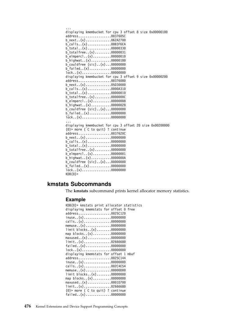
...displaying kmembucket for cpu 3 offset 8 size 0x00000100address..................0037605Cb_next..(x)..............062A2700b_calls..(x).............00B3F6EAb_total..(x).............00000330b_totalfree..(x).........00000031b_elmpercl..(x)..........00000010b_highwat..(x)...........00000180b_couldfree (sic)..(x)...00000000b_failed..(x)............00000000lock..(x)................00000000displaying kmembucket for cpu 3 offset 9 size 0x00000200address..................00376080b_next..(x)..............05D30000b_calls..(x).............0000A310b_total..(x).............00000010b_totalfree..(x).........0000000Cb_elmpercl..(x)..........00000008b_highwat..(x)...........00000028b_couldfree (sic)..(x)...00000000b_failed..(x)............00000000lock..(x)................00000000...displaying kmembucket for cpu 3 offset 20 size 0x00200000(0)> more (|C to quit) ? continueaddress..................0037620Cb_next..(x)..............00000000b_calls..(x).............00000000b_total..(x).............00000000b_totalfree..(x).........00000000b_elmpercl..(x)..........00000001b_highwat..(x)...........0000000Ab_couldfree (sic)..(x)...00000000b_failed..(x)............00000000lock..(x)................00000000KDB(0)>
kmstats SubcommandsThe kmstats subcommand prints kernel allocator memory statistics.
ExampleKDB(0)> kmstats print allocator statisticsdisplaying kmemstats for offset 0 freeaddress..................0025C120inuse..(x)...............00000000calls..(x)...............00000000memuse..(x)..............00000000limit blocks..(x)........00000000map blocks..(x)..........00000000maxused..(x).............00000000limit..(x)...............02666680failed..(x)..............00000000lock..(x)................00000000displaying kmemstats for offset 1 mbufaddress..................0025C144inuse..(x)...............0000000Dcalls..(x)...............002C4E54memuse..(x)..............00000D00limit blocks..(x)........00000000map blocks..(x)..........00000000maxused..(x).............0001D700limit..(x)...............02666680(0)> more (|C to quit) ? continuefailed..(x)..............00000000
476 Kernel Extensions and Device Support Programming Concepts
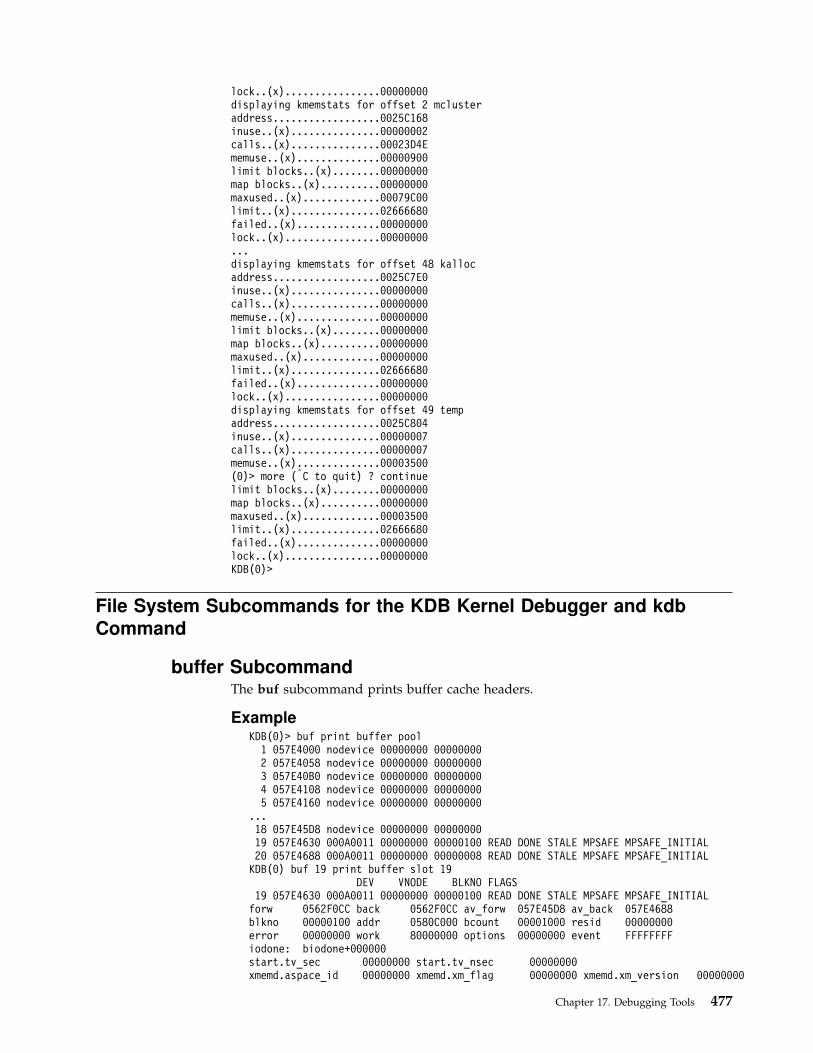
lock..(x)................00000000displaying kmemstats for offset 2 mclusteraddress..................0025C168inuse..(x)...............00000002calls..(x)...............00023D4Ememuse..(x)..............00000900limit blocks..(x)........00000000map blocks..(x)..........00000000maxused..(x).............00079C00limit..(x)...............02666680failed..(x)..............00000000lock..(x)................00000000...displaying kmemstats for offset 48 kallocaddress..................0025C7E0inuse..(x)...............00000000calls..(x)...............00000000memuse..(x)..............00000000limit blocks..(x)........00000000map blocks..(x)..........00000000maxused..(x).............00000000limit..(x)...............02666680failed..(x)..............00000000lock..(x)................00000000displaying kmemstats for offset 49 tempaddress..................0025C804inuse..(x)...............00000007calls..(x)...............00000007memuse..(x)..............00003500(0)> more (|C to quit) ? continuelimit blocks..(x)........00000000map blocks..(x)..........00000000maxused..(x).............00003500limit..(x)...............02666680failed..(x)..............00000000lock..(x)................00000000KDB(0)>
File System Subcommands for the KDB Kernel Debugger and kdb
Command
buffer SubcommandThe buf subcommand prints buffer cache headers.
ExampleKDB(0)> buf print buffer pool
1 057E4000 nodevice 00000000 000000002 057E4058 nodevice 00000000 000000003 057E40B0 nodevice 00000000 000000004 057E4108 nodevice 00000000 000000005 057E4160 nodevice 00000000 00000000
...18 057E45D8 nodevice 00000000 0000000019 057E4630 000A0011 00000000 00000100 READ DONE STALE MPSAFE MPSAFE_INITIAL20 057E4688 000A0011 00000000 00000008 READ DONE STALE MPSAFE MPSAFE_INITIAL
KDB(0) buf 19 print buffer slot 19DEV VNODE BLKNO FLAGS
19 057E4630 000A0011 00000000 00000100 READ DONE STALE MPSAFE MPSAFE_INITIALforw 0562F0CC back 0562F0CC av_forw 057E45D8 av_back 057E4688blkno 00000100 addr 0580C000 bcount 00001000 resid 00000000error 00000000 work 80000000 options 00000000 event FFFFFFFFiodone: biodone+000000start.tv_sec 00000000 start.tv_nsec 00000000xmemd.aspace_id 00000000 xmemd.xm_flag 00000000 xmemd.xm_version 00000000
Chapter 17. Debugging Tools 477

xmemd.subspace_id 00000000 xmemd.subspace_id2 00000000 xmemd.uaddr 00000000KDB(0)> pdt 17 print paging device slot 17 (the 1st FS)PDT address B69C0440 entry 17 of 511, type: FILESYSTEMnext pdt on i/o list (nextio) : FFFFFFFFdev_t or strategy ptr (device) : 000A0007last frame w/pend I/O (iotail) : FFFFFFFFfree buf_struct list (bufstr) : 056B2108total buf structs (nbufs) : 005Davailable (PAGING) (avail) : 0000JFS disk agsize (agsize) : 0800JFS inode agsize (iagsize) : 0800JFS log SCB index (logsidx) : 00035JFS fragments per page(fperpage): 1JFS compression type (comptype): 0JFS log2 bigalloc mult(bigexp) : 0disk map srval (dmsrval) : 00002021i/o's not finished (iocnt) : 00000000lock (lock) : E8003200KDB(0)> buf 056B2108 print paging device first free buffer
DEV VNODE BLKNO FLAGS0 056B2108 000A0007 00000000 00000048 DONE SPLIT MPSAFE MPSAFE_INITIAL
forw 0007DAB3 back 00000000 av_forw 056B20B0 av_back 00000000blkno 00000048 addr 00000000 bcount 00001000 resid 00000000error 00000000 work 00400000 options 00000000 event 00000000iodone: v_pfend+000000start.tv_sec 00000000 start.tv_nsec 00000000xmemd.aspace_id 00000000 xmemd.xm_flag 00000000 xmemd.xm_version 00000000xmemd.subspace_id 0083E01F xmemd.subspace_id2 00000000 xmemd.uaddr 00000000
hbuffer SubcommandThe hb subcommand prints buffer cache hash list of headers.
ExampleKDB(0)> hb print buffer cache hash lists
BUCKET HEAD COUNT0562F0CC 18 057E4630 10562F12C 26 057E4688 1KDB(0)> hb 26 print buffer cache hash list bucket 26
DEV VNODE BLKNO FLAGS20 057E4688 000A0011 00000000 00000008 READ DONE STALE MPSAFE MPSAFE_INITIAL
fbuffer SubcommandThe fb subcommand prints buffer cache freelist of headers.
ExampleKDB(0)> fb print free list buffer buckets
BUCKET HEAD COUNTbfreelist+000000 0001 057E4688 20KDB(0)> fb 1 print free list buffer bucket 1
DEV VNODE BLKNO FLAGS20 057E4688 000A0011 00000000 00000008 READ DONE STALE MPSAFE MPSAFE_INITIAL19 057E4630 000A0011 00000000 00000100 READ DONE STALE MPSAFE MPSAFE_INITIAL18 057E45D8 nodevice 00000000 0000000017 057E4580 nodevice 00000000 00000000
...2 057E4058 nodevice 00000000 000000001 057E4000 nodevice 00000000 00000000
gnode SubcommandThe gno subcommand prints the generic node structure.
478 Kernel Extensions and Device Support Programming Concepts

Example(0)> gno 09D0FD68 print gnodeGNODE............ 09D0FD68gn_type....... 00000002 gn_flags...... 00000000 gn_seg........ 0001A3FAgn_mwrcnt..... 00000000 gn_mrdcnt..... 00000000 gn_rdcnt...... 00000000gn_wrcnt...... 00000000 gn_excnt...... 00000000 gn_rshcnt..... 00000000gn_vnode...... 09D0FD28 gn_rdev....... 000A0010 gn_ops........ jfs_vopsgn_chan....... 00000000 gn_reclk_lock. 00000000 gn_reclk_lock@ 09D0FD9Cgn_reclk_event FFFFFFFF gn_filocks.... 00000000 gn_data....... 09D0FD58gn_type....... DIR
gfs SubcommandThe gfs subcommand prints the generic file system structure.
Example(0)> gfs gfs print gfs slot 1gfs_data. 00000000 gfs_flag. INIT VERSION4 VERSION42 VERSION421gfs_ops.. jfs_vfsops gn_ops... jfs_vops gfs_name. jfsgfs_init. jfs_init gfs_rinit jfs_rootinit gfs_type. JFSgfs_hold. 00000012(0)> gfs gfs+30 print gfs slot 2gfs_data. 00000000 gfs_flag. INIT VERSION4 VERSION42 VERSION421gfs_ops.. spec_vfsops gn_ops... spec_vnops gfs_name. sfsgfs_init. spec_init gfs_rinit nodev gfs_type. SFSgfs_hold. 00000000(0)> gfs gfs+60 print gfs slot 3gfs_data. 00000000 gfs_flag. REMOTE VERSION4gfs_ops.. 01D2ABF8 gn_ops... 01D2A328 gfs_name. nfsgfs_init. 01D2B5F0 gfs_rinit 00000000 gfs_type. NFSgfs_hold. 0000000E
file SubcommandThe file subcommand prints the file table.First, used files are printed (count > 0),then others.
Example(0)> file print file table
COUNT OFFSET DATA TYPE FLAGS1 file+000000 1 0000000000000100 09CD90C8 VNODE EXEC2 file+000030 1 0000000000000100 09CC4DE8 VNODE EXEC3 file+000060 1452 000000000019B084 09CC2B50 VNODE READ RSHARE4 file+000090 2 0000000000000100 09CFCD80 VNODE EXEC5 file+0000C0 2 0000000000000000 056CE008 VNODE READ WRITE6 file+0000F0 1 0000000000000000 056CE008 VNODE READ WRITE7 file+000120 1 0000000000000680 09CFF680 VNODE READ WRITE8 file+000150 1 0000000000000100 0B97BE0C VNODE EXEC9 file+000180 2 0000000000000000 056CE070 VNODE READ NONBLOCK10 file+0001B0 323 000000000000061C 09CC4F30 VNODE READ RSHARE11 file+0001E0 1 0000000000000000 0B7E8700 READ WRITE12 file+000210 16 000000000000061C 09CC5AB8 VNODE READ RSHARE13 file+000240 1 0000000000000000 0B221950 GNODE WRITE14 file+000270 1 0000000000000000 0B221A20 GNODE WRITE15 file+0002A0 2 000000000000055C 09CFFCE8 VNODE READ RSHARE16 file+0002D0 2 0000000000000000 09CFE9B0 VNODE WRITE17 file+000300 1 0000000000000000 0B7E8600 READ WRITE18 file+000330 1 0000000000000000 056CE008 VNODE READ19 file+000360 1 0000000000000000 09CFBB90 VNODE WRITE20 file+000390 3 000000000000284A 0B99A60C VNODE READ
(0)> more (|C to quit) ? Interrupted(0)> file 3 print file slot 3
COUNT OFFSET DATA TYPE FLAGS3 file+000060 1474 000000000019B084 09CC2B50 VNODE READ RSHARE
f_flag......... 00001001 f_count........ 000005C2
Chapter 17. Debugging Tools 479
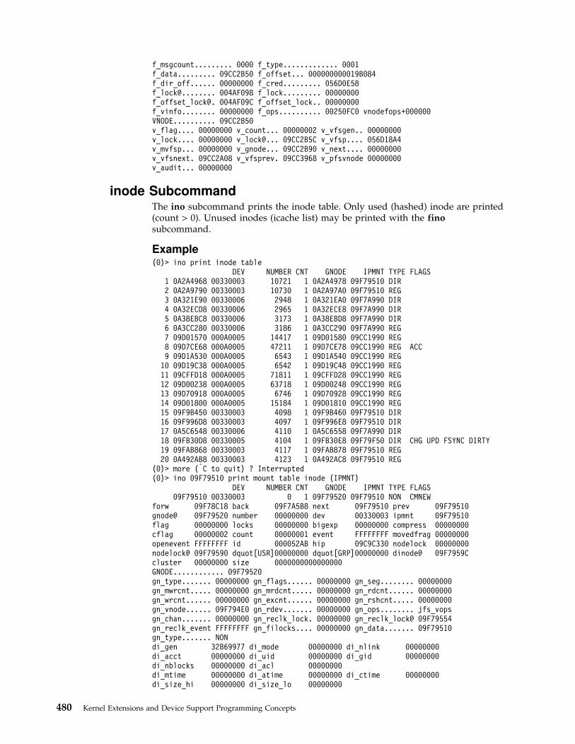
f_msgcount......... 0000 f_type............. 0001f_data......... 09CC2B50 f_offset... 000000000019B084f_dir_off...... 00000000 f_cred......... 056D0E58f_lock@........ 004AF098 f_lock......... 00000000f_offset_lock@. 004AF09C f_offset_lock.. 00000000f_vinfo........ 00000000 f_ops.......... 00250FC0 vnodefops+000000VNODE.......... 09CC2B50v_flag.... 00000000 v_count... 00000002 v_vfsgen.. 00000000v_lock.... 00000000 v_lock@... 09CC2B5C v_vfsp.... 056D18A4v_mvfsp... 00000000 v_gnode... 09CC2B90 v_next.... 00000000v_vfsnext. 09CC2A08 v_vfsprev. 09CC3968 v_pfsvnode 00000000v_audit... 00000000
inode SubcommandThe ino subcommand prints the inode table. Only used (hashed) inode are printed(count > 0). Unused inodes (icache list) may be printed with the finosubcommand.
Example(0)> ino print inode table
DEV NUMBER CNT GNODE IPMNT TYPE FLAGS1 0A2A4968 00330003 10721 1 0A2A4978 09F79510 DIR2 0A2A9790 00330003 10730 1 0A2A97A0 09F79510 REG3 0A321E90 00330006 2948 1 0A321EA0 09F7A990 DIR4 0A32ECD8 00330006 2965 1 0A32ECE8 09F7A990 DIR5 0A38EBC8 00330006 3173 1 0A38EBD8 09F7A990 DIR6 0A3CC280 00330006 3186 1 0A3CC290 09F7A990 REG7 09D01570 000A0005 14417 1 09D01580 09CC1990 REG8 09D7CE68 000A0005 47211 1 09D7CE78 09CC1990 REG ACC9 09D1A530 000A0005 6543 1 09D1A540 09CC1990 REG10 09D19C38 000A0005 6542 1 09D19C48 09CC1990 REG11 09CFFD18 000A0005 71811 1 09CFFD28 09CC1990 REG12 09D00238 000A0005 63718 1 09D00248 09CC1990 REG13 09D70918 000A0005 6746 1 09D70928 09CC1990 REG14 09D01800 000A0005 15184 1 09D01810 09CC1990 REG15 09F9B450 00330003 4098 1 09F9B460 09F79510 DIR16 09F996D8 00330003 4097 1 09F996E8 09F79510 DIR17 0A5C6548 00330006 4110 1 0A5C6558 09F7A990 DIR18 09FB30D8 00330005 4104 1 09FB30E8 09F79F50 DIR CHG UPD FSYNC DIRTY19 09FAB868 00330003 4117 1 09FAB878 09F79510 REG20 0A492AB8 00330003 4123 1 0A492AC8 09F79510 REG
(0)> more (|C to quit) ? Interrupted(0)> ino 09F79510 print mount table inode (IPMNT)
DEV NUMBER CNT GNODE IPMNT TYPE FLAGS09F79510 00330003 0 1 09F79520 09F79510 NON CMNEW
forw 09F78C18 back 09F7A5B8 next 09F79510 prev 09F79510gnode@ 09F79520 number 00000000 dev 00330003 ipmnt 09F79510flag 00000000 locks 00000000 bigexp 00000000 compress 00000000cflag 00000002 count 00000001 event FFFFFFFF movedfrag 00000000openevent FFFFFFFF id 000052AB hip 09C9C330 nodelock 00000000nodelock@ 09F79590 dquot[USR]00000000 dquot[GRP]00000000 dinode@ 09F7959Ccluster 00000000 size 0000000000000000GNODE............ 09F79520gn_type....... 00000000 gn_flags...... 00000000 gn_seg........ 00000000gn_mwrcnt..... 00000000 gn_mrdcnt..... 00000000 gn_rdcnt...... 00000000gn_wrcnt...... 00000000 gn_excnt...... 00000000 gn_rshcnt..... 00000000gn_vnode...... 09F794E0 gn_rdev....... 00000000 gn_ops........ jfs_vopsgn_chan....... 00000000 gn_reclk_lock. 00000000 gn_reclk_lock@ 09F79554gn_reclk_event FFFFFFFF gn_filocks.... 00000000 gn_data....... 09F79510gn_type....... NONdi_gen 32B69977 di_mode 00000000 di_nlink 00000000di_acct 00000000 di_uid 00000000 di_gid 00000000di_nblocks 00000000 di_acl 00000000di_mtime 00000000 di_atime 00000000 di_ctime 00000000di_size_hi 00000000 di_size_lo 00000000
480 Kernel Extensions and Device Support Programming Concepts
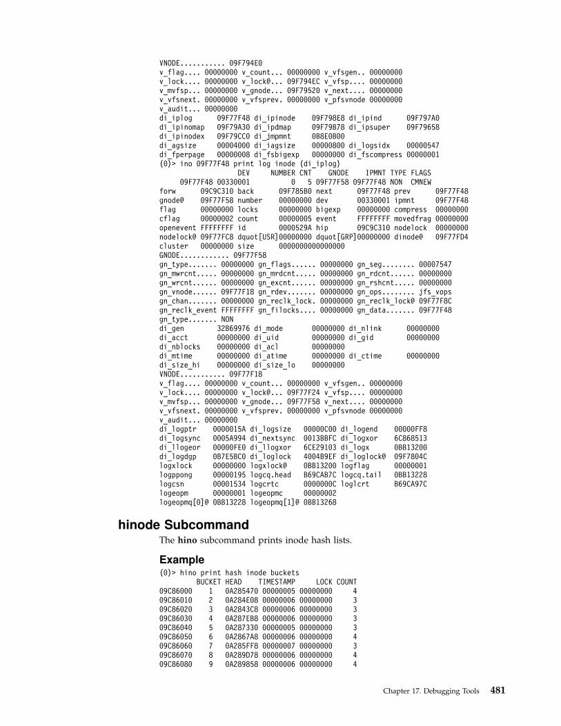
VNODE........... 09F794E0v_flag.... 00000000 v_count... 00000000 v_vfsgen.. 00000000v_lock.... 00000000 v_lock@... 09F794EC v_vfsp.... 00000000v_mvfsp... 00000000 v_gnode... 09F79520 v_next.... 00000000v_vfsnext. 00000000 v_vfsprev. 00000000 v_pfsvnode 00000000v_audit... 00000000di_iplog 09F77F48 di_ipinode 09F798E8 di_ipind 09F797A0di_ipinomap 09F79A30 di_ipdmap 09F79B78 di_ipsuper 09F79658di_ipinodex 09F79CC0 di_jmpmnt 0B8E0B00di_agsize 00004000 di_iagsize 00000800 di_logsidx 00000547di_fperpage 00000008 di_fsbigexp 00000000 di_fscompress 00000001(0)> ino 09F77F48 print log inode (di_iplog)
DEV NUMBER CNT GNODE IPMNT TYPE FLAGS09F77F48 00330001 0 5 09F77F58 09F77F48 NON CMNEW
forw 09C9C310 back 09F785B0 next 09F77F48 prev 09F77F48gnode@ 09F77F58 number 00000000 dev 00330001 ipmnt 09F77F48flag 00000000 locks 00000000 bigexp 00000000 compress 00000000cflag 00000002 count 00000005 event FFFFFFFF movedfrag 00000000openevent FFFFFFFF id 0000529A hip 09C9C310 nodelock 00000000nodelock@ 09F77FC8 dquot[USR]00000000 dquot[GRP]00000000 dinode@ 09F77FD4cluster 00000000 size 0000000000000000GNODE............ 09F77F58gn_type....... 00000000 gn_flags...... 00000000 gn_seg........ 00007547gn_mwrcnt..... 00000000 gn_mrdcnt..... 00000000 gn_rdcnt...... 00000000gn_wrcnt...... 00000000 gn_excnt...... 00000000 gn_rshcnt..... 00000000gn_vnode...... 09F77F18 gn_rdev....... 00000000 gn_ops........ jfs_vopsgn_chan....... 00000000 gn_reclk_lock. 00000000 gn_reclk_lock@ 09F77F8Cgn_reclk_event FFFFFFFF gn_filocks.... 00000000 gn_data....... 09F77F48gn_type....... NONdi_gen 32B69976 di_mode 00000000 di_nlink 00000000di_acct 00000000 di_uid 00000000 di_gid 00000000di_nblocks 00000000 di_acl 00000000di_mtime 00000000 di_atime 00000000 di_ctime 00000000di_size_hi 00000000 di_size_lo 00000000VNODE........... 09F77F18v_flag.... 00000000 v_count... 00000000 v_vfsgen.. 00000000v_lock.... 00000000 v_lock@... 09F77F24 v_vfsp.... 00000000v_mvfsp... 00000000 v_gnode... 09F77F58 v_next.... 00000000v_vfsnext. 00000000 v_vfsprev. 00000000 v_pfsvnode 00000000v_audit... 00000000di_logptr 0000015A di_logsize 00000C00 di_logend 00000FF8di_logsync 0005A994 di_nextsync 0013BBFC di_logxor 6C868513di_llogeor 00000FE0 di_llogxor 6CE29103 di_logx 0BB13200di_logdgp 0B7E5BC0 di_loglock 4004B9EF di_loglock@ 09F7804Clogxlock 00000000 logxlock@ 0BB13200 logflag 00000001logppong 00000195 logcq.head B69CAB7C logcq.tail 0BB13228logcsn 00001534 logcrtc 0000000C loglcrt B69CA97Clogeopm 00000001 logeopmc 00000002logeopmq[0]@ 0BB13228 logeopmq[1]@ 0BB13268
hinode SubcommandThe hino subcommand prints inode hash lists.
Example(0)> hino print hash inode buckets
BUCKET HEAD TIMESTAMP LOCK COUNT09C86000 1 0A285470 00000005 00000000 409C86010 2 0A284E08 00000006 00000000 309C86020 3 0A2843C8 00000006 00000000 309C86030 4 0A287EB8 00000006 00000000 309C86040 5 0A287330 00000005 00000000 309C86050 6 0A2867A8 00000006 00000000 409C86060 7 0A285FF8 00000007 00000000 309C86070 8 0A289D78 00000006 00000000 409C86080 9 0A289858 00000006 00000000 4
Chapter 17. Debugging Tools 481

09C86090 10 0A33E2D8 00000005 00000000 409C860A0 11 0A33E7F8 00000005 00000000 409C860B0 12 0A33EE60 00000005 00000000 409C860C0 13 0A33F758 00000005 00000000 409C860D0 14 0A28AE20 00000005 00000000 309C860E0 15 0A28A670 00000005 00000000 309C860F0 16 0A33CE58 00000005 00000000 409C86100 17 0A33D9E0 00000006 00000000 409C86110 18 0A5FF6D0 00000008 00000000 409C86120 19 0A5FD060 00000009 00000000 409C86130 20 0A5FC390 00000009 00000000 4(0)> more (|C to quit) ? Interrupted(0)> hino 18 print hash inode bucket 18HASH ENTRY( 18): 09C86110
DEV NUMBER CNT GNODE IPMNT TYPE FLAGS0A5FF6D0 00330003 2523 0 0A5FF6E0 09F79510 REG0A340E68 00330004 2524 0 0A340E78 09F78090 REG0A28CA50 00330003 10677 0 0A28CA60 09F79510 DIR0A1AFCA0 00330006 2526 0 0A1AFCB0 09F7A990 REG
icache SubcommandThe fino subcommand prints all the inode cache list.
Example(0)> fino print free inode cache
DEV NUMBER CNT GNODE IPMNT TYPE FLAGS1 09CABFA0 DEADBEEF 0 0 09CABFB0 09CA7178 CHR CMNOLINK2 0A8D3A70 DEADBEEF 0 0 0A8D3A80 09F7A990 REG CMNOLINK3 0A8F2528 DEADBEEF 0 0 0A8F2538 09CC6528 REG CMNOLINK4 0A7C66E0 DEADBEEF 0 0 0A7C66F0 09F7A990 REG CMNOLINK5 0A7BA568 DEADBEEF 0 0 0A7BA578 09F79F50 REG CMNOLINK6 0A78EC68 DEADBEEF 0 0 0A78EC78 09F78090 REG CMNOLINK7 0A7AF9B8 DEADBEEF 0 0 0A7AF9C8 09F79F50 REG CMNOLINK8 0A7B9230 DEADBEEF 0 0 0A7B9240 09F79F50 REG CMNOLINK9 0A8BDCA8 DEADBEEF 0 0 0A8BDCB8 09F79F50 LNK CMNOLINK10 0A8BE978 DEADBEEF 0 0 0A8BE988 09F7A990 REG CMNOLINK11 0A7C58C8 DEADBEEF 0 0 0A7C58D8 09F7A990 REG CMNOLINK12 0A78D6A0 DEADBEEF 0 0 0A78D6B0 09F78090 REG CMNOLINK13 0A7C4BF8 DEADBEEF 0 0 0A7C4C08 09F7A990 REG CMNOLINK14 0A78ADA0 DEADBEEF 0 0 0A78ADB0 09F78090 REG CMNOLINK15 0A7B8A80 DEADBEEF 0 0 0A7B8A90 09F79F50 REG CMNOLINK16 0A8BC970 DEADBEEF 0 0 0A8BC980 09F7A990 REG CMNOLINK17 0A8D1CF8 DEADBEEF 0 0 0A8D1D08 09F7A990 REG CMNOLINK18 0A7AE160 DEADBEEF 0 0 0A7AE170 09F79F50 REG CMNOLINK19 0A8EF998 DEADBEEF 0 0 0A8EF9A8 09CC6528 REG CMNOLINK20 0A7C41B8 DEADBEEF 0 0 0A7C41C8 09F7A990 REG CMNOLINK
(0)> more (|C to quit) ? Interrupted(0)> fino 1 print free inode slot 1
DEV NUMBER CNT GNODE IPMNT TYPE FLAGS09CABFA0 DEADBEEF 0 0 09CABFB0 09CA7178 CHR CMNOLINK
forw 09CABFA0 back 09CABFA0 next 0A8EF708 prev 0042AE60gnode@ 09CABFB0 number 00000000 dev DEADBEEF ipmnt 09CA7178flag 00000000 locks 00000000 bigexp 00000000 compress 00000000cflag 00000004 count 00000000 event FFFFFFFF movedfrag 00000000openevent FFFFFFFF id 00000045 hip 00000000 nodelock 00000000nodelock@ 09CAC020 dquot[USR]00000000 dquot[GRP]00000000 dinode@ 09CAC02Ccluster 00000000 size 0000000000000000GNODE............ 09CABFB0gn_type....... 00000004 gn_flags...... 00000000 gn_seg........ 00000000gn_mwrcnt..... 00000000 gn_mrdcnt..... 00000000 gn_rdcnt...... 00000000gn_wrcnt...... 00000000 gn_excnt...... 00000000 gn_rshcnt..... 00000000gn_vnode...... 09CABF70 gn_rdev....... 00030000 gn_ops........ jfs_vopsgn_chan....... 00000000 gn_reclk_lock. 00000000 gn_reclk_lock@ 09CABFE4gn_reclk_event FFFFFFFF gn_filocks.... 00000000 gn_data....... 09CABFA0gn_type....... CHR
482 Kernel Extensions and Device Support Programming Concepts

di_gen 00000000 di_mode 00000000 di_nlink 00000000di_acct 00000000 di_uid 00000000 di_gid 00000000di_nblocks 00000000 di_acl 00000000di_mtime 32B67A97 di_atime 32B67A97 di_ctime 32B67B4Bdi_size_hi 00000000 di_size_lo 00000000di_rdev 00030000VNODE........... 09CABF70v_flag.... 00000000 v_count... 00000000 v_vfsgen.. 00000000v_lock.... 00000000 v_lock@... 09CABF7C v_vfsp.... 00000000v_mvfsp... 00000000 v_gnode... 09CABFB0 v_next.... 00000000v_vfsnext. 09CABE28 v_vfsprev. 00000000 v_pfsvnode 00000000v_audit... 00000000
rnode SubcommandThe rno subcommand prints the remote node structure.
ExampleKDB(0)> rno 0A55D400 print rnodeRNODE............ 0A55D400freef........ 00000000 freeb....... 00000000hash......... 0A59A400 @vnode...... 0A55D40C@gnode....... 0A55D43C @fh......... 0A55D480fh[ 0]....... 0033000300000003 000A0000381F2F54fh[16]....... A3FA0000000A0000 08002F53C1030000flags........ 000001A0 error....... 00000000lastr........ 00000000 cred........ 0A5757F8altcred...... 00000000 unlcred..... 00000000unlname...... 00000000 unldvp...... 00000000size......... 001C3A90 @attr....... 0A55D4C0@attrtime.... 0A55D520 sdname...... 00000000sdvp......... 00000000 vh.......... 00000885sid.......... 00000885 acl......... 00000000aclsz........ 00000000 pcl......... 00000000pclsz........ 00000000 @lock....... 0A55D548rmevent...... FFFFFFFFflags........ RWVP ACLINVALID PCLINVALID
cku SubcommandThe cku subcommand prints the client kudp private structure.
ExampleKDB(0)> tpid print current thread
SLOT NAME STATE TID PRI CPUID CPU FLAGS WCHANthread+001E00 40*biod SLEEP 0028DD 03C 000 00000420 05F49A6CKDB(0)> f print current stackthread+001E00 STACK:[000191AC]e_block_thread+000214 ()[0004EE74]sosbwait+000190 (??, ??)[01AB64FC]clntkudp_callit_addr+0005A8 (0A1F3904, 00000006, 01AD8E48, 2FF3B198,
01AD8E54, 2FF3B1C8, 00000001, 00061A80)[01AB757C]clntkudp_callit+000020 (??, ??, ??, ??, ??, ??, ??, ??)[01AC4888]rfscall_progvers+0002C8 (??, ??, ??, ??, ??, ??, ??, ??)[01ACA384]nfsread+0000D8 (??, ??, ??, ??, ??, ??, ??, ??)[01ACB680]do_bio+000268 (??, ??)[01AC9868]async_daemon_x+000060 (??, ??)[01AC9920]async_daemon+000044 ()[000036F0].sys_call+000000 ()KDB(0)> cku @r22 print client kudp informationCKU_PRIVATE............ 0A1F3900flags............. 00000020 @client.......... 0A1F3904client.auth....... 054EE600 client.ops....... 01AC1898client.private.... 0A1F3900retrys............ 00000001 sock............. 05F49A00@addr............. 0A1F3918 @err............. 0A1F3928
Chapter 17. Debugging Tools 483

addr.sin_len...... 00000000 addr.sin_family.. 00000002addr.sin_port..... 00000801 addr.sin_addr.... 96B70101err.RE_errno...... 00000000 err.RE_why....... 00000000@outxdr........... 0A1F3934 @inxdr........... 0A1F394Coutxdr.x_op....... 00000000 outxdr.x_ops..... 01AC1430outxdr.x_public... 00000000 outxdr.x_private. 0A5A6078outxdr.x_base..... 05E9F600 outxdr.x_handy... 000021E8inxdr.x_op........ 00000001 inxdr.x_ops...... 01AC1430inxdr.x_public.... 00000000 inxdr.x_private.. 05E0A7A6inxdr.x_base...... 05E0A700 inxdr.x_handy.... 00000000outpos............ 00000014 outbuf........... 0A5A6000inbuf............. 05E0A746 inmbuf........... 05E0A700cred.............. 0A5757F8 timers........... 0A3CC788timeall........... 0A3CC798 feedback......... 01AD90ACxid............... 5397F6B5 trb.............. 0A54E280@buflock.......... 0A1F3990 bufevent......... FFFFFFFFflags............. INTR
vnode SubcommandThe vno subcommand prints the virtual node structure.
Example(0)> vnode print vnode table
COUNT VFSGEN GNODE VFSP DATAPTR TYPE FLAGS106 09D227B0 3 0 09D227F0 056D183C 00000000 REG126 09D1AB68 1 0 09D1ABA8 056D183C 00000000 REG130 09D196E8 1 0 09D19728 056D183C 00000000 REG135 09D18B60 1 0 09D18BA0 056D183C 05CC2D00 SOCK140 09D17E90 1 0 09D17ED0 056D183C 05D3F300 SOCK143 09D17970 1 0 09D179B0 056D183C 05CC2A00 SOCK148 09D17078 1 0 09D170B8 056D183C 05CC2800 SOCK154 09D14DE0 1 0 09D14E20 056D183C 00000000 REG162 09D13818 1 0 09D13858 056D183C 05D30E00 SOCK165 09D0D948 1 0 09D0D988 056D183C 00000000 DIR166 09D0D800 1 0 09D0D840 056D183C 00000000 DIR167 09D0D6B8 1 0 09D0D6F8 056D183C 00000000 DIR168 09D0D570 1 0 09D0D5B0 056D183C 00000000 DIR170 09D0D2E0 1 0 09D0D320 056D183C 00000000 DIR171 09D0D198 1 0 09D0D1D8 056D183C 00000000 DIR172 09D0D050 1 0 09D0D090 056D183C 00000000 DIR173 09D0CF08 1 0 09D0CF48 056D183C 00000000 DIR174 09D0CDC0 1 0 09D0CE00 056D183C 00000000 DIR175 09D0CC78 1 0 09D0CCB8 056D183C 00000000 DIR176 09D0CB30 1 0 09D0CB70 056D183C 00000000 DIR(0)> more (|C to quit) ? Interrupted(0)> vnode 106 print vnode slot 106
COUNT VFSGEN GNODE VFSP DATAPTR TYPE FLAGS106 09D227B0 3 0 09D227F0 056D183C 00000000 REGv_flag.... 00000000 v_count... 00000003 v_vfsgen.. 00000000v_lock.... 00000000 v_lock@... 09D227BC v_vfsp.... 056D183Cv_mvfsp... 00000000 v_gnode... 09D227F0 v_next.... 00000000v_vfsnext. 09D22668 v_vfsprev. 09D22B88 v_pfsvnode 00000000v_audit... 00000000
mount SubcommandThe vfs subcommand prints the virtual file system table.
Example(0)> vfs print vfs table
GFS MNTD MNTDOVER VNODES DATA TYPE FLAGS1 056D183C 0024F268 09CC08B8 00000000 0A5AADA0 0B221F68 JFS DEVMOUNT
... /dev/hd4 mounted over /2 056D18A4 0024F268 09CC2258 09CC0B48 0A545270 0B221F00 JFS DEVMOUNT
... /dev/hd2 mounted over /usr
484 Kernel Extensions and Device Support Programming Concepts
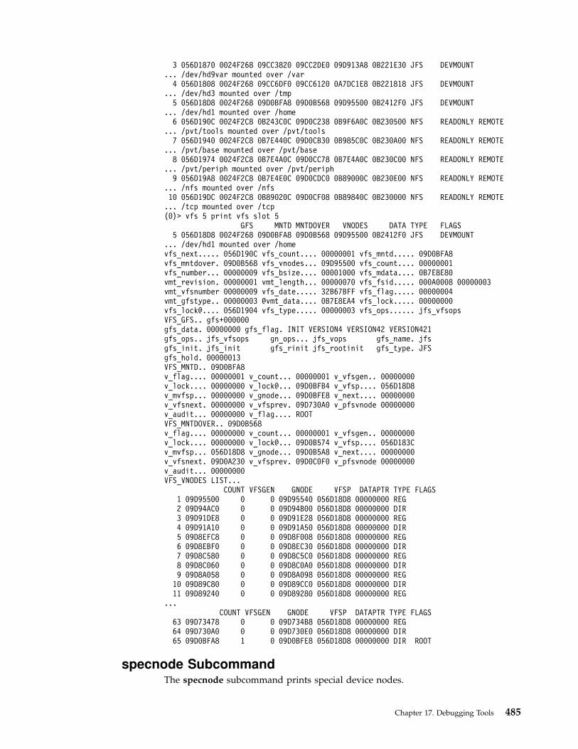
3 056D1870 0024F268 09CC3820 09CC2DE0 09D913A8 0B221E30 JFS DEVMOUNT... /dev/hd9var mounted over /var
4 056D1808 0024F268 09CC6DF0 09CC6120 0A7DC1E8 0B221818 JFS DEVMOUNT... /dev/hd3 mounted over /tmp
5 056D18D8 0024F268 09D0BFA8 09D0B568 09D95500 0B2412F0 JFS DEVMOUNT... /dev/hd1 mounted over /home
6 056D190C 0024F2C8 0B243C0C 09D0C238 0B9F6A0C 0B230500 NFS READONLY REMOTE... /pvt/tools mounted over /pvt/tools
7 056D1940 0024F2C8 0B7E440C 09D0CB30 0B985C0C 0B230A00 NFS READONLY REMOTE... /pvt/base mounted over /pvt/base
8 056D1974 0024F2C8 0B7E4A0C 09D0CC78 0B7E4A0C 0B230C00 NFS READONLY REMOTE... /pvt/periph mounted over /pvt/periph
9 056D19A8 0024F2C8 0B7E4E0C 09D0CDC0 0B89000C 0B230E00 NFS READONLY REMOTE... /nfs mounted over /nfs10 056D19DC 0024F2C8 0B89020C 09D0CF08 0B89840C 0B230000 NFS READONLY REMOTE... /tcp mounted over /tcp(0)> vfs 5 print vfs slot 5
GFS MNTD MNTDOVER VNODES DATA TYPE FLAGS5 056D18D8 0024F268 09D0BFA8 09D0B568 09D95500 0B2412F0 JFS DEVMOUNT
... /dev/hd1 mounted over /homevfs_next..... 056D190C vfs_count.... 00000001 vfs_mntd..... 09D0BFA8vfs_mntdover. 09D0B568 vfs_vnodes... 09D95500 vfs_count.... 00000001vfs_number... 00000009 vfs_bsize.... 00001000 vfs_mdata.... 0B7E8E80vmt_revision. 00000001 vmt_length... 00000070 vfs_fsid..... 000A0008 00000003vmt_vfsnumber 00000009 vfs_date..... 32B67BFF vfs_flag..... 00000004vmt_gfstype.. 00000003 @vmt_data.... 0B7E8EA4 vfs_lock..... 00000000vfs_lock@.... 056D1904 vfs_type..... 00000003 vfs_ops...... jfs_vfsopsVFS_GFS.. gfs+000000gfs_data. 00000000 gfs_flag. INIT VERSION4 VERSION42 VERSION421gfs_ops.. jfs_vfsops gn_ops... jfs_vops gfs_name. jfsgfs_init. jfs_init gfs_rinit jfs_rootinit gfs_type. JFSgfs_hold. 00000013VFS_MNTD.. 09D0BFA8v_flag.... 00000001 v_count... 00000001 v_vfsgen.. 00000000v_lock.... 00000000 v_lock@... 09D0BFB4 v_vfsp.... 056D18D8v_mvfsp... 00000000 v_gnode... 09D0BFE8 v_next.... 00000000v_vfsnext. 00000000 v_vfsprev. 09D730A0 v_pfsvnode 00000000v_audit... 00000000 v_flag.... ROOTVFS_MNTDOVER.. 09D0B568v_flag.... 00000000 v_count... 00000001 v_vfsgen.. 00000000v_lock.... 00000000 v_lock@... 09D0B574 v_vfsp.... 056D183Cv_mvfsp... 056D18D8 v_gnode... 09D0B5A8 v_next.... 00000000v_vfsnext. 09D0A230 v_vfsprev. 09D0C0F0 v_pfsvnode 00000000v_audit... 00000000VFS_VNODES LIST...
COUNT VFSGEN GNODE VFSP DATAPTR TYPE FLAGS1 09D95500 0 0 09D95540 056D18D8 00000000 REG2 09D94AC0 0 0 09D94B00 056D18D8 00000000 DIR3 09D91DE8 0 0 09D91E28 056D18D8 00000000 REG4 09D91A10 0 0 09D91A50 056D18D8 00000000 DIR5 09D8EFC8 0 0 09D8F008 056D18D8 00000000 REG6 09D8EBF0 0 0 09D8EC30 056D18D8 00000000 DIR7 09D8C580 0 0 09D8C5C0 056D18D8 00000000 REG8 09D8C060 0 0 09D8C0A0 056D18D8 00000000 DIR9 09D8A058 0 0 09D8A098 056D18D8 00000000 REG10 09D89C80 0 0 09D89CC0 056D18D8 00000000 DIR11 09D89240 0 0 09D89280 056D18D8 00000000 REG
...COUNT VFSGEN GNODE VFSP DATAPTR TYPE FLAGS
63 09D73478 0 0 09D734B8 056D18D8 00000000 REG64 09D730A0 0 0 09D730E0 056D18D8 00000000 DIR65 09D0BFA8 1 0 09D0BFE8 056D18D8 00000000 DIR ROOT
specnode SubcommandThe specnode subcommand prints special device nodes.
Chapter 17. Debugging Tools 485

Example(0)> file file+002880 print file entry
COUNT OFFSET DATA TYPE FLAGS217 file+002880 6 000000000002818F 056CE314 VNODE READ WRITEf_flag......... 00000003 f_count........ 00000006f_msgcount......... 0000 f_type............. 0001f_data......... 056CE314 f_offset... 000000000002818Ff_dir_off...... 00000000 f_cred......... 0B988E58f_lock@........ 004B18B8 f_lock......... 00000000f_offset_lock@. 004B18BC f_offset_lock.. 00000000f_vinfo........ 00000000 f_ops.......... 00250FC0 vnodefops+000000VNODE.......... 056CE314v_flag.... 00000000 v_count... 00000002 v_vfsgen.. 00000000v_lock.... 00000000 v_lock@... 056CE320 v_vfsp.... 01AC9840v_mvfsp... 00000000 v_gnode... 0B2215C8 v_next.... 00000000v_vfsnext. 00000000 v_vfsprev. 00000000 v_pfsvnode 09CD5D88v_audit... 00000000(0)> gno 0B2215C8 print gnode entryGNODE............ 0B2215C8gn_type....... 00000004 gn_flags...... 00000000 gn_seg........ 007FFFFFgn_mwrcnt..... 00000000 gn_mrdcnt..... 00000000 gn_rdcnt...... 00000000gn_wrcnt...... 00000000 gn_excnt...... 00000000 gn_rshcnt..... 00000000gn_vnode...... 056CE314 gn_rdev....... 000E0000 gn_ops........ spec_vnopsgn_chan....... 00000000 gn_reclk_lock. 00000000 gn_reclk_lock@ 0B2215FCgn_reclk_event FFFFFFFF gn_filocks.... 00000000 gn_data....... 0B2215B8gn_type....... CHR(0)> specno 0B2215B8 print special node entrySPECNODE........ 0B2215B8sn_next...... 00000000 sn_count..... 00000001 sn_lock...... 00000000sn_gnode..... 0B2215C8 sn_pfsgnode.. 09CD5DC8 sn_attr...... 00000000sn_dev....... 000E0000 sn_chan...... 00000000 sn_vnode..... 056CE314sn_ops....... 00275518 sn_devnode... 0B221C80 sn_type...... CHRSN_VNODE........ 056CE314v_flag.... 00000000 v_count... 00000002 v_vfsgen.. 00000000v_lock.... 00000000 v_lock@... 056CE320 v_vfsp.... 01AC9840v_mvfsp... 00000000 v_gnode... 0B2215C8 v_next.... 00000000v_vfsnext. 00000000 v_vfsprev. 00000000 v_pfsvnode 09CD5D88v_audit... 00000000SN_GNODE......... 0B2215C8gn_type....... 00000004 gn_flags...... 00000000 gn_seg........ 007FFFFFgn_mwrcnt..... 00000000 gn_mrdcnt..... 00000000 gn_rdcnt...... 00000000gn_wrcnt...... 00000000 gn_excnt...... 00000000 gn_rshcnt..... 00000000gn_vnode...... 056CE314 gn_rdev....... 000E0000 gn_ops........ spec_vnopsgn_chan....... 00000000 gn_reclk_lock. 00000000 gn_reclk_lock@ 0B2215FCgn_reclk_event FFFFFFFF gn_filocks.... 00000000 gn_data....... 0B2215B8gn_type....... CHRSN_PFSGNODE...... 09CD5DC8gn_type....... 00000004 gn_flags...... 00000000 gn_seg........ 00000000gn_mwrcnt..... 00000000 gn_mrdcnt..... 00000000 gn_rdcnt...... 00000000gn_wrcnt...... 00000000 gn_excnt...... 00000000 gn_rshcnt..... 00000000gn_vnode...... 09CD5D88 gn_rdev....... 000E0000 gn_ops........ jfs_vopsgn_chan....... 00000000 gn_reclk_lock. 00000000 gn_reclk_lock@ 09CD5DFCgn_reclk_event FFFFFFFF gn_filocks.... 00000000 gn_data....... 09CD5DB8gn_type....... CHR
devnode SubcommandThe devno subcommand prints device nodes.
Example(0)> devno print device node table
DEV CNT SPECNODE GNODE LASTR PDATA TYPE1 0B241758 00300000 1 0B2212E0 0B241768 00000000 05CB4E00 CHR2 0B221C18 00100000 1 00000000 0B221C28 00000000 00000000 CHR3 0B221940 00110000 2 00000000 0B221950 00000000 00000000 BLK4 0B221870 00020000 1 0B221140 0B221880 00000000 00000000 CHR
486 Kernel Extensions and Device Support Programming Concepts

5 0B7E5A10 00120001 2 00000000 0B7E5A20 00000000 00000000 BLK6 0B241070 00020001 1 0B8A3EF0 0B241080 00000000 00000000 CHR7 0B2219A8 00020002 1 0B221008 0B2219B8 00000000 00000000 CHR8 0B2218D8 00130000 1 00000000 0B2218E8 00000000 00000000 CHR9 0B7E5BB0 00330001 1 00000000 0B7E5BC0 00000000 00000000 BLK10 0B221A10 00130001 1 00000000 0B221A20 00000000 00000000 CHR11 0B241008 00330002 1 00000000 0B241018 00000000 00000000 BLK12 0B7E59A8 00130002 1 00000000 0B7E59B8 00000000 00000000 CHR13 0B7E5C18 00330003 1 00000000 0B7E5C28 00000000 00000000 BLK14 0B7E5808 00130003 1 00000000 0B7E5818 00000000 00000000 CHR15 0B7E5A78 00330004 1 00000000 0B7E5A88 00000000 00000000 BLK16 0B7E5C80 00330005 1 00000000 0B7E5C90 00000000 00000000 BLK17 0B7E5CE8 00330006 1 00000000 0B7E5CF8 00000000 00000000 BLK18 0B2416F0 00040000 1 0B2211A8 0B241700 00000000 00000000 MPC19 0B221BB0 00150000 3 0B221688 0B221BC0 00000000 05CC3E00 CHR20 0B2410D8 00060000 1 0B221480 0B2410E8 00000000 00000000 CHR
(0)> more (|C to quit) ? Interrupted(0)> devno 3 print device node slot 3
DEV CNT SPECNODE GNODE LASTR PDATA TYPE3 0B221940 00110000 2 00000000 0B221950 00000000 00000000 BLK
forw...... 00DD6CD8 back...... 00DD6CD8 lock...... 00000000GNODE............ 0B221950gn_type....... 00000003 gn_flags...... 00000000 gn_seg........ 007FFFFFgn_mwrcnt..... 00000000 gn_mrdcnt..... 00000000 gn_rdcnt...... 00000000gn_wrcnt...... 00000002 gn_excnt...... 00000000 gn_rshcnt..... 00000000gn_vnode...... 00000000 gn_rdev....... 00110000 gn_ops........ 00000000gn_chan....... 00000000 gn_reclk_lock. 00000000 gn_reclk_lock@ 0B221984gn_reclk_event 00000000 gn_filocks.... 00000000 gn_data....... 0B221940gn_type....... BLKSPECNODES....... 00000000
fifonode SubcommandThe fifono subcommand prints fifo nodes.
Example(0)> fifono print fifo node table
PFSGNODE SPECNODE SIZE RCNT WCNT TYPE FLAG1 056D1C08 09D15EC8 0B2210D8 00000000 1 1 FIFO WWRT2 056D1CA8 09D1BB08 0B7E5070 00000000 1 1 FIFO RBLK WWRT
(0)> fifono 1 print fifo node slot 1PFSGNODE SPECNODE SIZE RCNT WCNT TYPE FLAG
1 056D1C08 09D15EC8 0B2210D8 00000000 1 1 FIFO WWRTff_forw.... 00DD6D44 ff_back.... 00DD6D44 ff_dev..... FFFFFFFFff_poll.... 00000001 ff_rptr.... 00000000 ff_wptr.... 00000000ff_revent.. FFFFFFFF ff_wevent.. FFFFFFFF ff_buf..... 056D1C34SPECNODE........ 0B2210D8sn_next...... 00000000 sn_count..... 00000001 sn_lock...... 00000000sn_gnode..... 0B2210E8 sn_pfsgnode.. 09D15EC8 sn_attr...... 00000000sn_dev....... FFFFFFFF sn_chan...... 00000000 sn_vnode..... 056CE070sn_ops....... 002751B0 sn_devnode... 056D1C08 sn_type...... FIFOSN_VNODE........ 056CE070v_flag.... 00000000 v_count... 00000002 v_vfsgen.. 00000000v_lock.... 00000000 v_lock@... 056CE07C v_vfsp.... 01AC9810v_mvfsp... 00000000 v_gnode... 0B2210E8 v_next.... 00000000v_vfsnext. 00000000 v_vfsprev. 00000000 v_pfsvnode 09D15E88v_audit... 00000000SN_GNODE......... 0B2210E8gn_type....... 00000008 gn_flags...... 00000000 gn_seg........ 007FFFFFgn_mwrcnt..... 00000000 gn_mrdcnt..... 00000000 gn_rdcnt...... 00000000gn_wrcnt...... 00000000 gn_excnt...... 00000000 gn_rshcnt..... 00000000gn_vnode...... 056CE070 gn_rdev....... FFFFFFFF gn_ops........ fifo_vnopsgn_chan....... 00000000 gn_reclk_lock. 00000000 gn_reclk_lock@ 0B22111Cgn_reclk_event 00000000 gn_filocks.... 00000000 gn_data....... 0B2210D8gn_type....... FIFOSN_PFSGNODE...... 09D15EC8
Chapter 17. Debugging Tools 487
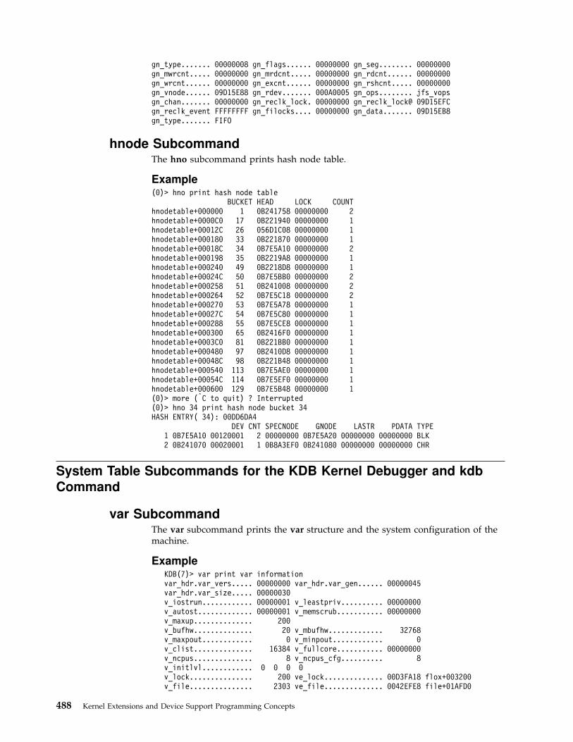
gn_type....... 00000008 gn_flags...... 00000000 gn_seg........ 00000000gn_mwrcnt..... 00000000 gn_mrdcnt..... 00000000 gn_rdcnt...... 00000000gn_wrcnt...... 00000000 gn_excnt...... 00000000 gn_rshcnt..... 00000000gn_vnode...... 09D15E88 gn_rdev....... 000A0005 gn_ops........ jfs_vopsgn_chan....... 00000000 gn_reclk_lock. 00000000 gn_reclk_lock@ 09D15EFCgn_reclk_event FFFFFFFF gn_filocks.... 00000000 gn_data....... 09D15EB8gn_type....... FIFO
hnode SubcommandThe hno subcommand prints hash node table.
Example(0)> hno print hash node table
BUCKET HEAD LOCK COUNThnodetable+000000 1 0B241758 00000000 2hnodetable+0000C0 17 0B221940 00000000 1hnodetable+00012C 26 056D1C08 00000000 1hnodetable+000180 33 0B221870 00000000 1hnodetable+00018C 34 0B7E5A10 00000000 2hnodetable+000198 35 0B2219A8 00000000 1hnodetable+000240 49 0B2218D8 00000000 1hnodetable+00024C 50 0B7E5BB0 00000000 2hnodetable+000258 51 0B241008 00000000 2hnodetable+000264 52 0B7E5C18 00000000 2hnodetable+000270 53 0B7E5A78 00000000 1hnodetable+00027C 54 0B7E5C80 00000000 1hnodetable+000288 55 0B7E5CE8 00000000 1hnodetable+000300 65 0B2416F0 00000000 1hnodetable+0003C0 81 0B221BB0 00000000 1hnodetable+000480 97 0B2410D8 00000000 1hnodetable+00048C 98 0B221B48 00000000 1hnodetable+000540 113 0B7E5AE0 00000000 1hnodetable+00054C 114 0B7E5EF0 00000000 1hnodetable+000600 129 0B7E5B48 00000000 1(0)> more (|C to quit) ? Interrupted(0)> hno 34 print hash node bucket 34HASH ENTRY( 34): 00DD6DA4
DEV CNT SPECNODE GNODE LASTR PDATA TYPE1 0B7E5A10 00120001 2 00000000 0B7E5A20 00000000 00000000 BLK2 0B241070 00020001 1 0B8A3EF0 0B241080 00000000 00000000 CHR
System Table Subcommands for the KDB Kernel Debugger and kdb
Command
var SubcommandThe var subcommand prints the var structure and the system configuration of themachine.
ExampleKDB(7)> var print var informationvar_hdr.var_vers..... 00000000 var_hdr.var_gen...... 00000045var_hdr.var_size..... 00000030v_iostrun............ 00000001 v_leastpriv.......... 00000000v_autost............. 00000001 v_memscrub........... 00000000v_maxup.............. 200v_bufhw.............. 20 v_mbufhw............. 32768v_maxpout............ 0 v_minpout............ 0v_clist.............. 16384 v_fullcore........... 00000000v_ncpus.............. 8 v_ncpus_cfg.......... 8v_initlvl............ 0 0 0 0v_lock............... 200 ve_lock.............. 00D3FA18 flox+003200v_file............... 2303 ve_file.............. 0042EFE8 file+01AFD0
488 Kernel Extensions and Device Support Programming Concepts
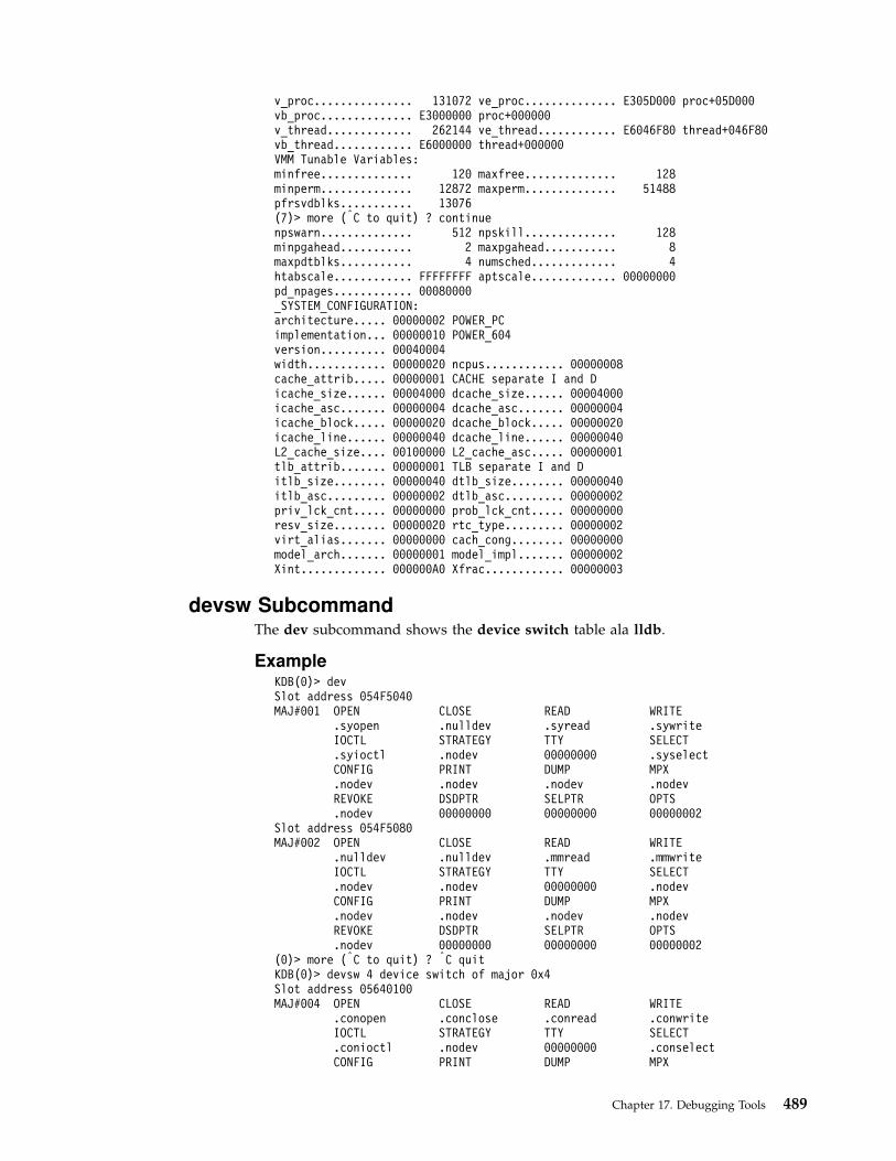
v_proc............... 131072 ve_proc.............. E305D000 proc+05D000vb_proc.............. E3000000 proc+000000v_thread............. 262144 ve_thread............ E6046F80 thread+046F80vb_thread............ E6000000 thread+000000VMM Tunable Variables:minfree.............. 120 maxfree.............. 128minperm.............. 12872 maxperm.............. 51488pfrsvdblks........... 13076(7)> more (|C to quit) ? continuenpswarn.............. 512 npskill.............. 128minpgahead........... 2 maxpgahead........... 8maxpdtblks........... 4 numsched............. 4htabscale............ FFFFFFFF aptscale............. 00000000pd_npages............ 00080000_SYSTEM_CONFIGURATION:architecture..... 00000002 POWER_PCimplementation... 00000010 POWER_604version.......... 00040004width............ 00000020 ncpus............ 00000008cache_attrib..... 00000001 CACHE separate I and Dicache_size...... 00004000 dcache_size...... 00004000icache_asc....... 00000004 dcache_asc....... 00000004icache_block..... 00000020 dcache_block..... 00000020icache_line...... 00000040 dcache_line...... 00000040L2_cache_size.... 00100000 L2_cache_asc..... 00000001tlb_attrib....... 00000001 TLB separate I and Ditlb_size........ 00000040 dtlb_size........ 00000040itlb_asc......... 00000002 dtlb_asc......... 00000002priv_lck_cnt..... 00000000 prob_lck_cnt..... 00000000resv_size........ 00000020 rtc_type......... 00000002virt_alias....... 00000000 cach_cong........ 00000000model_arch....... 00000001 model_impl....... 00000002Xint............. 000000A0 Xfrac............ 00000003
devsw SubcommandThe dev subcommand shows the device switch table ala lldb.
ExampleKDB(0)> devSlot address 054F5040MAJ#001 OPEN CLOSE READ WRITE
.syopen .nulldev .syread .sywriteIOCTL STRATEGY TTY SELECT.syioctl .nodev 00000000 .syselectCONFIG PRINT DUMP MPX.nodev .nodev .nodev .nodevREVOKE DSDPTR SELPTR OPTS.nodev 00000000 00000000 00000002
Slot address 054F5080MAJ#002 OPEN CLOSE READ WRITE
.nulldev .nulldev .mmread .mmwriteIOCTL STRATEGY TTY SELECT.nodev .nodev 00000000 .nodevCONFIG PRINT DUMP MPX.nodev .nodev .nodev .nodevREVOKE DSDPTR SELPTR OPTS.nodev 00000000 00000000 00000002
(0)> more (|C to quit) ? |C quitKDB(0)> devsw 4 device switch of major 0x4Slot address 05640100MAJ#004 OPEN CLOSE READ WRITE
.conopen .conclose .conread .conwriteIOCTL STRATEGY TTY SELECT.conioctl .nodev 00000000 .conselectCONFIG PRINT DUMP MPX
Chapter 17. Debugging Tools 489

.conconfig .nodev .nodev .conmpxREVOKE DSDPTR SELPTR OPTS.conrevoke 00000000 00000000 00000006
timer SubcommandThe trb subcommand displays timer request block ala lldb. Subcommand optionare selected thru the menu, or directly entered.
ExampleKDB(4)> trb timer request block subcommand usageUsage: trb [CPU selector] [1-9]CPU selector is '*' for all CPUs, 'cpu n' for CPU n, default is current CPU
Timer Request Block Information Menu1. TRB Maintenance Structure - Routine Addresses2. System TRB3. Thread Specified TRB4. Current Thread TRB's5. Address Specified TRB6. Active TRB Chain7. Free TRB Chain8. Clock Interrupt Handler Information9. Current System Time - System Timer Constants
Please enter an option number: <CR/LF>KDB(4)> trb * 6 print all active timer request blocksCPU #0 Active List
CPU PRI ID SECS NSECS DATA FUNC05689080 0000 0005 FFFFFFFE 00003BBA 23C3B080 05689080 sys_timer+00000005689600 0000 0003 FFFFFFFE 00003BBA 27DAC680 00000000 pffastsched+00000005689580 0000 0003 FFFFFFFE 00003BBA 2911BD80 00000000 pfslowsched+0000000B05A600 0000 0005 00001751 00003BBA 2ADBC480 0B05A618 rtsleep_end+00000005689500 0000 0003 FFFFFFFE 00003BBB 23186B00 00000000 if_slowsched+0000000B05A480 0000 0003 FFFFFFFE 00003BBF 2D5B4980 00000000 01B633F0CPU #1 Active List
CPU PRI ID SECS NSECS DATA FUNC05689100 0001 0005 FFFFFFFE 00003BBA 23C38E80 05689100 sys_timer+000000CPU #2 Active List
CPU PRI ID SECS NSECS DATA FUNC05689180 0002 0005 FFFFFFFE 00003BBA 23C37380 05689180 sys_timer+0000000B05A500 0002 0005 00001525 00003BE6 0CFF9500 0B05A518 rtsleep_end+000000CPU #3 Active List
CPU PRI ID SECS NSECS DATA FUNC05689200 0003 0005 FFFFFFFE 00003BBA 23C39F80 05689200 sys_timer+000000(4)> more (|C to quit) ? continue05689880 0003 0005 00000003 00003BBB 01B73180 00000000 sched_timer_post+0000000B05A580 0003 0005 00000001 00003BBB 0BCA7300 0000000E interval_end+000000CPU #4 Active List
CPU PRI ID SECS NSECS DATA FUNC05689280 0004 0005 FFFFFFFE 00003BBA 23C3A980 05689280 sys_timer+000000CPU #5 Active List
CPU PRI ID SECS NSECS DATA FUNC05689300 0005 0005 FFFFFFFE 00003BBA 23C39800 05689300 sys_timer+00000005689780 0005 0005 FFFFFFFF 00003BBF 1B052C00 05C62C40 01ADD6FCCPU #6 Active List
CPU PRI ID SECS NSECS DATA FUNC05689380 0006 0005 FFFFFFFE 00003BBA 23C3C200 05689380 sys_timer+000000CPU #7 Active List
CPU PRI ID SECS NSECS DATA FUNC05689400 0007 0005 FFFFFFFE 00003BBA 23C38180 05689400 sys_timer+00000005689680 0007 0003 FFFFFFFE 00003BBA 2DDD3480 00000000 threadtimer+000000KDB(4)> trb cpu 1 6 print active list of processor 1CPU #1 TRB #1 on Active ListTimer address......................05689100trb->to_next.......................00000000trb->knext.........................00000000trb->kprev.........................00000000
490 Kernel Extensions and Device Support Programming Concepts
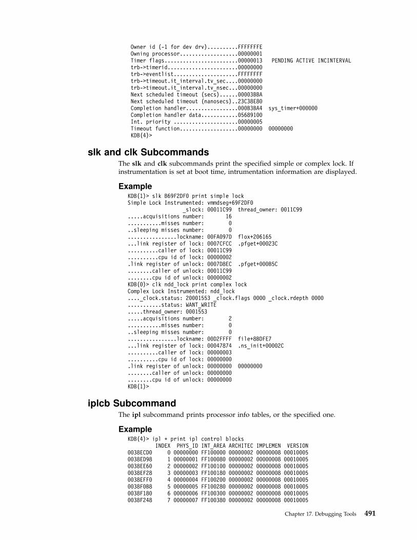
Owner id (-1 for dev drv)..........FFFFFFFEOwning processor...................00000001Timer flags........................00000013 PENDING ACTIVE INCINTERVALtrb->timerid.......................00000000trb->eventlist.....................FFFFFFFFtrb->timeout.it_interval.tv_sec....00000000trb->timeout.it_interval.tv_nsec...00000000Next scheduled timeout (secs)......00003BBANext scheduled timeout (nanosecs)..23C38E80Completion handler.................000B3BA4 sys_timer+000000Completion handler data............05689100Int. priority .....................00000005Timeout function...................00000000 00000000KDB(4)>
slk and clk SubcommandsThe slk and clk subcommands print the specified simple or complex lock. Ifinstrumentation is set at boot time, intrumentation information are displayed.
ExampleKDB(1)> slk B69F2DF0 print simple lockSimple Lock Instrumented: vmmdseg+69F2DF0
_slock: 00011C99 thread_owner: 0011C99.....acquisitions number: 16...........misses number: 0..sleeping misses number: 0................lockname: 00FA097D flox+206165...link register of lock: 0007CFCC .pfget+00023C..........caller of lock: 00011C99..........cpu id of lock: 00000002.link register of unlock: 0007D8EC .pfget+000B5C........caller of unlock: 00011C99........cpu id of unlock: 00000002KDB(0)> clk ndd_lock print complex lockComplex Lock Instrumented: ndd_lock...._clock.status: 20001553 _clock.flags 0000 _clock.rdepth 0000...........status: WANT_WRITE.....thread_owner: 0001553.....acquisitions number: 2...........misses number: 0..sleeping misses number: 0................lockname: 00D2FFFF file+8BDFE7...link register of lock: 00047874 .ns_init+00002C..........caller of lock: 00000003..........cpu id of lock: 00000000.link register of unlock: 00000000 00000000........caller of unlock: 00000000........cpu id of unlock: 00000000KDB(1)>
iplcb SubcommandThe ipl subcommand prints processor info tables, or the specified one.
ExampleKDB(4)> ipl * print ipl control blocks
INDEX PHYS_ID INT_AREA ARCHITEC IMPLEMEN VERSION0038ECD0 0 00000000 FF100000 00000002 00000008 000100050038ED98 1 00000001 FF100080 00000002 00000008 000100050038EE60 2 00000002 FF100100 00000002 00000008 000100050038EF28 3 00000003 FF100180 00000002 00000008 000100050038EFF0 4 00000004 FF100200 00000002 00000008 000100050038F0B8 5 00000005 FF100280 00000002 00000008 000100050038F180 6 00000006 FF100300 00000002 00000008 000100050038F248 7 00000007 FF100380 00000002 00000008 00010005
Chapter 17. Debugging Tools 491
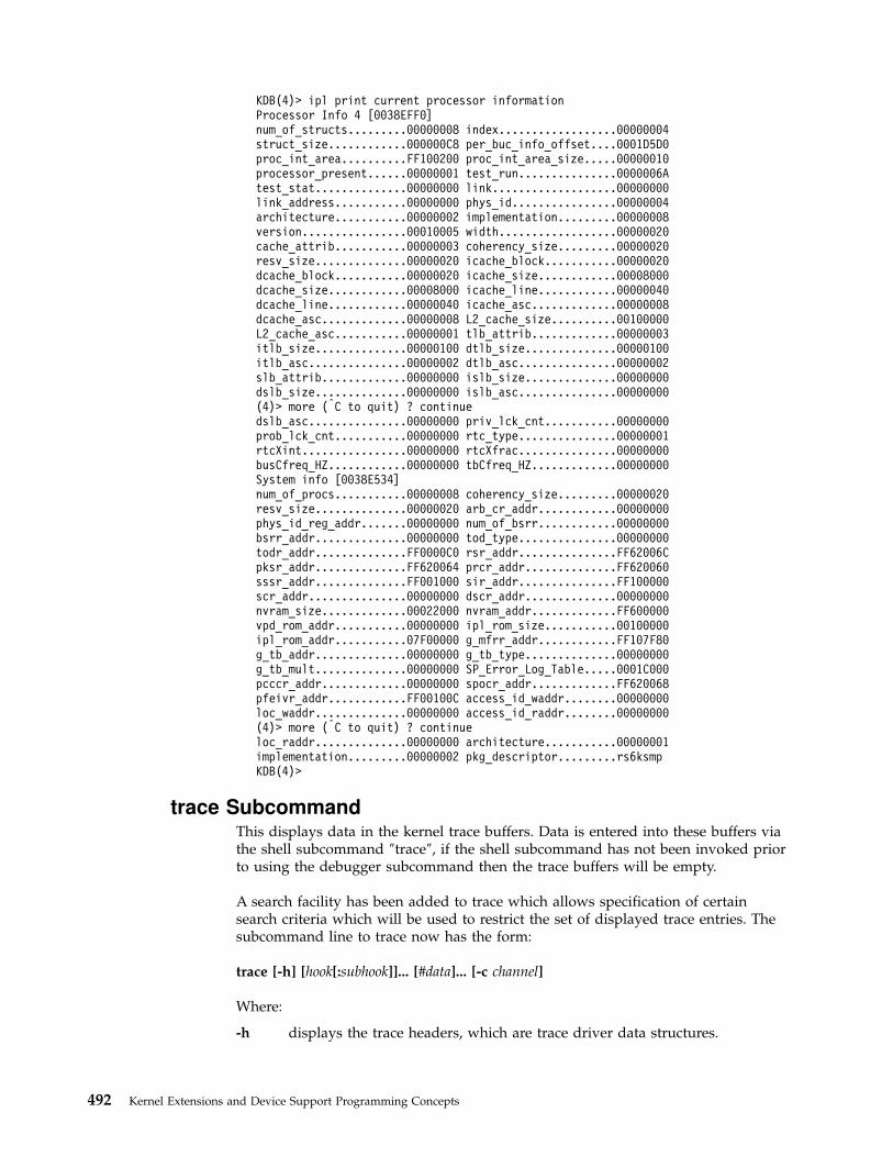
KDB(4)> ipl print current processor informationProcessor Info 4 [0038EFF0]num_of_structs.........00000008 index..................00000004struct_size............000000C8 per_buc_info_offset....0001D5D0proc_int_area..........FF100200 proc_int_area_size.....00000010processor_present......00000001 test_run...............0000006Atest_stat..............00000000 link...................00000000link_address...........00000000 phys_id................00000004architecture...........00000002 implementation.........00000008version................00010005 width..................00000020cache_attrib...........00000003 coherency_size.........00000020resv_size..............00000020 icache_block...........00000020dcache_block...........00000020 icache_size............00008000dcache_size............00008000 icache_line............00000040dcache_line............00000040 icache_asc.............00000008dcache_asc.............00000008 L2_cache_size..........00100000L2_cache_asc...........00000001 tlb_attrib.............00000003itlb_size..............00000100 dtlb_size..............00000100itlb_asc...............00000002 dtlb_asc...............00000002slb_attrib.............00000000 islb_size..............00000000dslb_size..............00000000 islb_asc...............00000000(4)> more (|C to quit) ? continuedslb_asc...............00000000 priv_lck_cnt...........00000000prob_lck_cnt...........00000000 rtc_type...............00000001rtcXint................00000000 rtcXfrac...............00000000busCfreq_HZ............00000000 tbCfreq_HZ.............00000000System info [0038E534]num_of_procs...........00000008 coherency_size.........00000020resv_size..............00000020 arb_cr_addr............00000000phys_id_reg_addr.......00000000 num_of_bsrr............00000000bsrr_addr..............00000000 tod_type...............00000000todr_addr..............FF0000C0 rsr_addr...............FF62006Cpksr_addr..............FF620064 prcr_addr..............FF620060sssr_addr..............FF001000 sir_addr...............FF100000scr_addr...............00000000 dscr_addr..............00000000nvram_size.............00022000 nvram_addr.............FF600000vpd_rom_addr...........00000000 ipl_rom_size...........00100000ipl_rom_addr...........07F00000 g_mfrr_addr............FF107F80g_tb_addr..............00000000 g_tb_type..............00000000g_tb_mult..............00000000 SP_Error_Log_Table.....0001C000pcccr_addr.............00000000 spocr_addr.............FF620068pfeivr_addr............FF00100C access_id_waddr........00000000loc_waddr..............00000000 access_id_raddr........00000000(4)> more (|C to quit) ? continueloc_raddr..............00000000 architecture...........00000001implementation.........00000002 pkg_descriptor.........rs6ksmpKDB(4)>
trace SubcommandThis displays data in the kernel trace buffers. Data is entered into these buffers viathe shell subcommand ″trace″, if the shell subcommand has not been invoked priorto using the debugger subcommand then the trace buffers will be empty.
A search facility has been added to trace which allows specification of certainsearch criteria which will be used to restrict the set of displayed trace entries. Thesubcommand line to trace now has the form:
trace [-h] [hook[:subhook]]... [#data]... [-c channel]
Where:
-h displays the trace headers, which are trace driver data structures.
492 Kernel Extensions and Device Support Programming Concepts

-c selects the channel number from the subcommand line, otherwise it will beprompted for.
The trace subcommand displays the contents of the specified channel, based onany search criteria which was entered on the subcommand line.
ExampleKDB(0)> trace -c 0 1b0 1b1 1b2 1b3 1b4 1b5 1b6 1b7 1b8 1b9trace VMM hooks onlyTrace Channel 0 (253 entries)Current queue starts at 0x0A919000 and ends at 0x0A939000Current entry is #128 of 128 at 0x0A92CDB4
Hook ID: VMM_DELETE (0x000001B1) Hook Type: HKTY_GT (0x0000000E)ThreadIdent: 0x0000ECE5Subhook ID/HookData: 0x0000D0: 0x0000DD1BD1: 0xA0801020D2: 0x000000D3D3: 0x00019AC0D4: 0x00000000
Current queue starts at 0x0A919000 and ends at 0x0A939000Current entry is #127 of 128 at 0x0A92CD84
Hook ID: VMM_DELETE (0x000001B1) Hook Type: HKTY_GT (0x0000000E)ThreadIdent: 0x0000ECE5Subhook ID/HookData: 0x0000D0: 0x0000DD1BD1: 0xA0801020D2: 0x000000D6D3: 0x0001BF3A
(0)> more (|C to quit) ? continueD4: 0x00000000
Current queue starts at 0x0A919000 and ends at 0x0A939000Current entry is #126 of 128 at 0x0A92CD04
Hook ID: VMM_DELETE (0x000001B1) Hook Type: HKTY_GT (0x0000000E)ThreadIdent: 0x0000ECE5Subhook ID/HookData: 0x0000D0: 0x0000DD1BD1: 0xA0801020D2: 0x000000D8D3: 0x00019AA2D4: 0x00000000
Current queue starts at 0x0A919000 and ends at 0x0A939000Current entry is #125 of 128 at 0x0A92CC74
Hook ID: VMM_DELETE (0x000001B1) Hook Type: HKTY_GT (0x0000000E)ThreadIdent: 0x0000ECE5Subhook ID/HookData: 0x0000D0: 0x0000DD1BD1: 0xA0801020D2: 0x000000D7D3: 0x0001A643
(0)> more (|C to quit) ? continueD4: 0x00000000
Current queue starts at 0x0A919000 and ends at 0x0A939000Current entry is #124 of 128 at 0x0A92CBF4
Hook ID: VMM_DELETE (0x000001B1) Hook Type: HKTY_GT (0x0000000E)ThreadIdent: 0x0000ECE5Subhook ID/HookData: 0x0000D0: 0x0000DD1BD1: 0xA0801020D2: 0x000000BAD3: 0x0001A947D4: 0x00000000
Current queue starts at 0x0A919000 and ends at 0x0A939000Current entry is #123 of 128 at 0x0A92CBD4
Hook ID: VMM_GETPARENT (0x000001B6) Hook Type: HKTY_GT (0x0000000E)ThreadIdent: 0x0000CE27
Chapter 17. Debugging Tools 493

Subhook ID/HookData: 0x0000D0: 0x000023A4D1: 0xA0801020D2: 0x000000E0D3: 0x0001D42E
(0)> more (|C to quit) ? continueD4: 0x00000000
Current queue starts at 0x0A919000 and ends at 0x0A939000Current entry is #122 of 128 at 0x0A92CBB4
Hook ID: VMM (0x000001B0) Hook Type: HKTY_GT (0x0000000E)ThreadIdent: 0x0000CE27Subhook ID/HookData: 0x0000D0: 0x000023A4D1: 0xA0801020D2: 0x000000E0D3: 0x0001D42ED4: 0x00000000
Current queue starts at 0x0A919000 and ends at 0x0A939000Current entry is #121 of 128 at 0x0A92CB94
Hook ID: VMM_DELETE (0x000001B1) Hook Type: HKTY_GT (0x0000000E)ThreadIdent: 0x0000ECE5Subhook ID/HookData: 0x0000D0: 0x0000DD1BD1: 0xA0801020D2: 0x000000B9D3: 0x000181B4
...Hook ID: VMM_PGEXCT (0x000001B2) Hook Type: HKTY_GT (0x0000000E)ThreadIdent: 0x000114EDSubhook ID/HookData: 0x0000D0: 0x00009D93D1: 0xA1801000D2: 0x0000FF99D3: 0x00000000
(0)> more (|C to quit) ? continueD4: 0x00000000
End of Trace
Net Subcommands for the KDB Kernel Debugger and kdb Command
ifnet SubcommandThe ifnet subcommand prints interface information, or the specified one.
ExampleKDB(0)> ifnet display interfaceSLOT 1 —— IFNET INFO ——(@0x00325138)——
flags:0x08080009(UP|LOOPBACK)
timer:00000 metric:00address: 127.0.0.1
ifq_head:0x00000000 if_init():0x00000000 ipackets:00000190ifq_tail:0x00000000 if_output():0x00080E9C ierrors: 00000ifq_len:00000 if_ioctl():0x00080E90 opackets:00000195ifq_maxlen:00000 if_reset():0x00000000 oerrors: 00000ifq_drops:00050 if_watchdog():0x00000000
SLOT 2 —— IFNET INFO ——(@0x05583800)——flags:0x08080863
(UP|BROADCAST|NOTRAILERS|RUNNING|CANTCHANGE)timer:00000 metric:00
address: 129.183.67.8ifq_head:0x01A2CACC if_init():0x00000000 ipackets:00003456ifq_tail:0x00000000 if_output():0x01A2CAA8 ierrors: 00000
494 Kernel Extensions and Device Support Programming Concepts

ifq_len:00000 if_ioctl():0x01A2CAC0 opackets:00000088ifq_maxlen:00000 if_reset():0x00000000 oerrors: 00000ifq_drops:00000 if_watchdog():0x00000000
KDB(0)>
tcb SubcommandThe tcb subcommand prints TCP blocks, or the specified one.
ExampleKDB(0)> tcb display TCP blocksSLOT 1 TCB ————- INPCB INFO ——(@0x05F4AB00)——
next:0x05CD0E80 prev:0x01C033B8 head:0x01C033B8ppcb:0x05F9FF00 inp_socket:0x05FA4C00lport: 23 laddr:0x96B70114fport: 3972 faddr:0x81B7600D
—— SOCKET INFO ——(@05FA4C00)——typeCommandCommand.. 0001 (STREAM)optsCommandCommand.. 010C (REUSEADDR|KEEPALIVE|OOBINLINE)lingerCommandCommand 0000 stateCommandCommand. 0182 (ISCONNECTED|PRIV|NBIO)pcbCommand.. 05F4AB00 protoCommand 01C01F80 lockCommand. 05FB1680 headCommand.00000000 q0CommandCommand 00000000 qCommandCommand. 00000000 dqCommandCommand00000000 q0lenCommandCommand. 0000 qlenCommandCommand.. 0000 qlimitCommandCommand0000 dqlenCommandCommand. 0000 timeoCommandCommand. 0000 errorCommandCommand.0000 specialCommand.. 0808 pgidCommand. 00000000 oobmark. 00000000snd:ccCommandCommand 00000000 hiwatCommand 00004000 mbcntCommand 00000000mbmaxCommand 00010000 lowatCommand 00001000 mbCommandCommand 00000000 selCommand..00000000 eventsCommandCommand 0000 iodone.. 00000000 ioargs.. 00000000 lastpkt.05FA9D00 wakeone. FFFFFFFF timerCommand 00000000 timeoCommand 00000000flagsCommandCommand. 0000 () wakeup.. 00000000 wakearg. 00000000 lockCommand. 05FB1684
rcv:ccCommandCommand 00000000 hiwatCommand 00004000 mbcntCommand 00000000 mbmaxCommand00010000 lowatCommand 00000001 mbCommandCommand 00000000 selCommand.. 00000000eventsCommandCommand 0004 iodone.. 00000000 ioargs.. 00000000 lastpkt. 05FA4900wakeone. FFFFFFFF timerCommand 00000000 timeoCommand 00000000 flagsCommandCommand.0008 (SEL) wakeup.. 00000000 wakearg. 00000000 lockCommand. 05FB1688
(0)> more (|C to quit) ? |C quitKDB(0)>
udb SubcommandThe udb subcommand prints UDP blocks, or the specified one.
ExampleKDB(0)> udb display UDP blocksSLOT 1 UDB ————- INPCB INFO ——(@0x05F31300)——
next:0x05D21A00 prev:0x01C07170 head:0x01C07170ppcb:0x00000000 inp_socket:0x05F2D200lport: 1595 laddr:0x00000000fport: 0 faddr:0x00000000
—— SOCKET INFO ——(@05F2D200)——typeCommandCommand.. 0002 (DGRAM)optsCommandCommand.. 0000 ()lingerCommandCommand 0000 stateCommandCommand. 0080 (PRIV)pcbCommand.. 05F31300 protoCommand 01C01F48 lockCommand. 05F2F900 headCommand.00000000 q0CommandCommand 00000000 qCommandCommand. 00000000 dqCommandCommand00000000 q0lenCommandCommand. 0000 qlenCommandCommand.. 0000 qlimitCommandCommand0000 dqlenCommandCommand. 0000 timeoCommandCommand. 0000 errorCommandCommand.0000 specialCommand.. 0808 pgidCommand. 00000000 oobmark. 00000000
snd:ccCommandCommand 00000000 hiwatCommand 00010000 mbcntCommand 00000000 mbmaxCommand00020000 lowatCommand 00001000 mbCommandCommand 00000000 selCommand.. 00000000eventsCommandCommand 0000 iodone.. 00000000 ioargs.. 00000000 lastpkt. 00000000wakeone. FFFFFFFF timerCommand 00000000 timeoCommand 00000000 flagsCommandCommand.0000 () wakeup.. 00000000 wakearg. 00000000 lockCommand. 05F2F904
rcv:ccCommandCommand 00000000 hiwatCommand 00010000 mbcntCommand 00000000 mbmaxCommand00020000 lowatCommand 00000001 mbCommandCommand 00000000 selCommand.. 00000000eventsCommandCommand 0000 iodone.. 00000000 ioargs.. 00000000 lastpkt. 05D3DD00
Chapter 17. Debugging Tools 495

wakeone. FFFFFFFF timerCommand 00000000 timeoCommand 0000005E flagsCommandCommand.0000 () wakeup.. 00000000 wakearg. 00000000 lockCommand. 05F2F908
(0)> more (|C to quit) ? |C quitKDB(0)>
sock SubcommandThe sock subcommand prints TCP UDP sockets, or the specified one. It is possibleto select only one protocol: tcp or udp.
ExampleKDB(0)> sock tcp display TCP sockets—— TCP ——(inpcb: @0x05F4AB00)———— SOCKET INFO ——(@05FA4C00)——
typeCommandCommand.. 0001 (STREAM)optsCommandCommand.. 010C (REUSEADDR|KEEPALIVE|OOBINLINE)lingerCommandCommand 0000 stateCommandCommand. 0182 (ISCONNECTED|PRIV|NBIO)pcbCommand.. 05F4AB00 protoCommand 01C01F80 lockCommand. 05FB1680 headCommand.00000000 q0CommandCommand 00000000 qCommandCommand. 00000000 dqCommandCommand00000000 q0lenCommandCommand. 0000 qlenCommandCommand.. 0000 qlimitCommandCommand0000 dqlenCommandCommand. 0000 timeoCommandCommand. 0000 errorCommandCommand.0000 specialCommand.. 0808 pgidCommand. 00000000 oobmark. 00000000
snd:ccCommandCommand 00000002 hiwatCommand 00004000 mbcntCommand 00000100 mbmaxCommand00010000 lowatCommand 00001000 mbCommandCommand 05F2D600 selCommand.. 00000000eventsCommandCommand 0000 iodone.. 00000000 ioargs.. 00000000 lastpkt. 05F2D600wakeone. FFFFFFFF timerCommand 00000000 timeoCommand 00000000 flagsCommandCommand.0000 () wakeup.. 00000000 wakearg. 00000000 lockCommand. 05FB1684
rcv:ccCommandCommand 00000000 hiwatCommand 00004000 mbcntCommand 00000000 mbmaxCommand00010000 lowatCommand 00000001 mbCommandCommand 00000000 selCommand.. 00000000eventsCommandCommand 0005 iodone.. 00000000 ioargs.. 00000000 lastpkt. 05E1A200wakeone. FFFFFFFF timerCommand 00000000 timeoCommand 00000000 flagsCommandCommand.0008 (SEL) wakeup.. 00000000 wakearg. 00000000 lockCommand. 05FB1688
—— TCP ——(inpcb: @0x05CD0E80)———— SOCKET INFO ——(@05CABA00)——
typeCommandCommand.. 0001 (STREAM)(0)> more (|C to quit) ? |C quitKDB(0)>
tcpcb SubcommandThe tcpcb subcommand prints TCP control blocks, or the specified one.
ExampleKDB(0)> tcpcb display TCB control blocks—— TCP ——(inpcb: @0x05B17F80)———— TCPCB ——(@0x05B26C00)——
seg_next 0x05B26C00 seg_prev 0x05B26C00 t_state 0x04 (ESTABLISHED)timers: TCPT_REXMT:3 TCPT_PERSIST:0 TCPT_KEEP:14400 TCPT_2MSL:0t_txtshift 0 t_txtcur 3 t_dupacks 0 t_maxseg 1460 t_force 0flags:0x0000 ()t_template 0x00000000 inpcb 0x00000000snd_cwnd: 0x00009448 snd_ssthresh:0x3FFFC000snd_una: 0x1EADFCA0 snd_nxt: 0x1EADFCA2 snd_up: 0x1EADFCA0snd=wl1: 0xE3BDEEAF snd_wl2: 0x1EADFCA0 iss: 0x1EAD8401snd_wnd: 16060 rcv_wnd: 16060t_idle: 0x00000000 t_rtt: 0x00000001 t_rtseq: 0x1EADFCA0t_srtt: 0x00000007 t_rttvar: 0x00000003max_sndwnd:16060 t_iobc:0x00 t_oobflags:0x00 ()
—— TCP ——(inpcb: @0x05B2D000)———— TCPCB ——(@0x05B28300)——
seg_next 0x05B28300 seg_prev 0x05B28300 t_state 0x04 (ESTABLISHED)timers: TCPT_REXMT:0 TCPT_PERSIST:0 TCPT_KEEP:4719 TCPT_2MSL:0t_txtshift 0 t_txtcur 3 t_dupacks 0 t_maxseg 1460 t_force 0flags:0x0000 ()
496 Kernel Extensions and Device Support Programming Concepts

t_template 0x00000000 inpcb 0x00000000snd_cwnd: 0x0000111C snd_ssthresh:0x3FFFC000
(0)> more (|C to quit) ?|C quitKDB(0)>
mbuf SubcommandThe mbuf subcommand prints TCP UDP message buffers, or the specified one. Itis possible to select only one protocol: tcp or udp.
ExampleKDB(0)> mbuf display message buffers—— TCP ——(inpcb: @0x05F4AB00)———— SND ——(sock: @0x05FA4C00)——mCommandCommandCommandCommandCommand 05E2E900 m_nextCommandCommandCommand. 00000000
m_nextpktCommandCommand. 00000000m_lenCommandCommandCommand.. 00000004 m_dataCommandCommandCommand. 05E2E91C
m_typeCommand.. 0001 DATAm_flagsCommandCommandCommand 0002 (M_PKTHDR)m_pkthdr.lenCommand. 00000004 m_pkthdr.rcvif.. 00000000——————————————————————————
05E2E91C: 7566 0D0A uf..—— TCP ——(inpcb: @0x05CD0E80)———— TCP ——(inpcb: @0x05CA6B80)———— TCP ——(inpcb: @0x05EB0A00)———— TCP ——(inpcb: @0x05D21E00)———— TCP ——(inpcb: @0x05CA6880)———— TCP ——(inpcb: @0x05DB1F00)———— TCP ——(inpcb: @0x05DB1F80)———— TCP ——(inpcb: @0x05DB1C80)———— TCP ——(inpcb: @0x05DB1D00)———— TCP ——(inpcb: @0x05DB1D80)———— TCP ——(inpcb: @0x05DB1E00)———— TCP ——(inpcb: @0x05F31580)———— TCP ——(inpcb: @0x05F31900)———— TCP ——(inpcb: @0x05F31980)——(0)> more (|C to quit) ? |C quitKDB(0)>
VMM Subcommands for the KDB Kernel Debugger and kdb Command
Most of vmm subcommands can be used without argument, then all choices areprinted. It is also possible to enter the selection as argument.
vmker SubcommandThe vmker subcommand prints virtual memory kernel data.
example:
KDB(4)> vmker display virtual memory kernel dataVMM Kernel Data:vmm srval (vmmsrval) : 00000801pgsp map srval (dmapsrval) : 00001803ram disk srval (ramdsrval) : 00000000kernel ext srval (kexsrval) : 00002004iplcb vaddr (iplcbptr) : 0045A000hashbits (hashbits) : 00000010hash shift amount (stoibits) : 0000000Brsvd pgsp blks (psrsvdblks) : 00000500total page frames (nrpages) : 0001FF58bad page frames (badpages) : 00000000free page frames (numfrb) : 000198AFmax perm frames (maxperm) : 000195E0num perm frames (numperm) : 0000125A
Chapter 17. Debugging Tools 497

total pgsp blks (numpsblks) : 00050000free pgsp blks (psfreeblks) : 0004CE2Cbase config seg (bconfsrval) : 0000580Brsvd page frames (pfrsvdblks) : 00006644fetch protect (nofetchprot): 00000000shadow srval (ukernsrval) : 60000000num client frames (numclient) : 00000014max client frames (maxclient) : 000195E0kernel srval (kernsrval) : 00000000STOI/ITOS mask (stoimask) : 0000001FSTOI/ITOS sid mask(stoinio) : 00000000max file pageout (maxpout) : 00000000min file pageout (minpout) : 00000000repage table size (rptsize) : 00010000next free in rpt (rptfree) : 00000000repage decay rate (rpdecay) : 0000005Aglobal repage cnt (sysrepage) : 00000000swhashmask (swhashmask) : 0000FFFFhashmask (hashmask) : 0000FFFFcachealign (cachealign) : 00001000overflows (overflows) : 00000000reloads (reloads) : 0000078Epmap_lock_addr (pmap_lock_addr): 00000000compressed segs (numcompress): 00000000compressed files (noflush) : 00000000extended iplcb (iplcbxptr) : 00000000alias hash mask (ahashmask) : 000000FFmax pgs to delete (pd_npages) : 00080000vrld xlate hits (vrldhits) : 00000000vrld xlate misses (vrldmisses) : 0000004Cvmm 1 swpft (...srval) : 00003006vmm 2 swpft (...srval) : 00003807vmm 3 swpft (...srval) : 00004008vmm 4 swpft (...srval) : 00004809vmm swhat (...srval) : 00002805# of ptasegments (numptasegs) : 00000001vmkerlock (vmkerlock) : E8000100ame srval(s) (amesrval[0] : 0000600Cptaseg(s) (ptasegs[1] : 00001002
rmap SubcommandThe rmap subcommand prints the real address range mapping table.
example:
KDB(2)> rmap * display real address range mappingsSLOT RADDR SIZE ALIGN WIMG <name>
vmrmap+000028 0001 0000000000000000 00458D51 00000000 0002 Kernelvmrmap+000048 0002 000000001FF20000 00028000 00000000 0002 IPL control blockvmrmap+000068 0003 0000000000459000 00058000 00001000 0002 MSTvmrmap+000088 0004 00000000008BF000 001ABCE0 00000000 0002 RAMDvmrmap+0000A8 0005 0000000000A6B000 00025001 00000000 0002 BCFGvmrmap+0000E8 0007 0000000000C00000 00400000 00400000 0002 PFTvmrmap+000108 0008 00000000004B1000 0007FD60 00001000 0002 PVTvmrmap+000128 0009 0000000000531000 00200000 00001000 0002 PVLISTvmrmap+000148 000A 0000000001000000 0067DDE0 00001000 0002 s/w PFTvmrmap+000168 000B 0000000000731000 00040000 00001000 0002 s/w HATvmrmap+000188 000C 0000000000771000 00001000 00001000 0002 APTvmrmap+0001A8 000D 0000000000772000 00000200 00001000 0002 AHATvmrmap+0001C8 000E 0000000000773000 00080000 00001000 0002 RPTvmrmap+0001E8 000F 00000000007F3000 00020000 00001000 0002 RPHATvmrmap+000208 0010 0000000000813000 0000D000 00001000 0002 PDTvmrmap+000228 0011 0000000000820000 00001000 00001000 0002 PTARvmrmap+000248 0012 0000000000821000 00002000 00001000 0002 PTADvmrmap+000268 0013 0000000000823000 00003000 00001000 0002 PTAIvmrmap+000288 0014 0000000000826000 00001000 00001000 0002 DMAP
498 Kernel Extensions and Device Support Programming Concepts

vmrmap+0002C8 0016 00000000FF000000 00000100 00000000 0005 SYSREGvmrmap+0002E8 0017 00000000FF100000 00000600 00000000 0005 SYSINTvmrmap+000308 0018 00000000FF600000 00022000 00000000 0005 NVRAMvmrmap+000328 0019 000000001FD00000 00080000 00000000 0006 TCEvmrmap+000348 001A 000000001FC00000 00080000 00000000 0006 TCEvmrmap+000368 001B 00000000FF001000 00000014 00000000 0005 System Specific Reg.vmrmap+000388 001C 00000000FF180000 00000004 00000000 0005 APRKDB(2)> rmap 16 display real address range mappings of slot 16RMAP entry 0016 of 001F: SYSREG> valid> range is in I/O spaceReal address : 00000000FF000000Effective address : 00000000E0000000Size : 00000100Alignment : 00000000WIMG bits : 5KDB(2)> rmap display page intervals utilized by the VMMVMM RMAP, usage: rmap [*][<slot>]Enter the RMAP index (0-001F): 20 out of range slotInterval entry 0 of 5.... Memory holes (1 intervals)
0 : [01FF58,100000)Interval entry 1 of 5.... Fixed kernel memory (4 intervals)
0 : [000000,0000F8)1 : [0000F7,00011A)2 : [000119,000125)3 : [0002E6,0002E9)
Interval entry 2 of 5.... Released kernel memory (1 intervals)
0 : [00011A,000124)Interval entry 3 of 5.... Fixed common memory (2 intervals)
0 : [000488,000495)1 : [000494,000495)
Interval entry 4 of 5.... Page replacement skips (6 intervals)
0 : [000000,000827)1 : [000C00,00167E)2 : [01FC00,01FC80)3 : [01FD00,01FD80)4 : [01FF20,01FF48)5 : [01FF58,100000)
Interval entry 5 of 5.... Debugger skips (3 intervals)
0 : [0004B1,000731)1 : [000C00,001000)2 : [01FF58,100000)
pfhdata SubcommandThe pfhdata subcommand prints virtual memory control variables.
example:
KDB(2)> pfhdata display virtual memory control variablesVMM Control Variables: B69C8000 vmmdseg +69C80001st non-pinned page (firstnf) : 000000001st free sid entry (sidfree) : 000003F01st delete pending (sidxmem) : 00000000highest sid entry (hisid) : 0000040Cfblru page-outs (numpout) : 00000000fblru remote pg-outs (numremote) : 00000000frames not pinned (pfavail) : 0001E062next lru candidate (lruptr) : 00000000v_sync cursor (syncptr) : 00000000last pdt on i/o list (iotail) : FFFFFFFF
Chapter 17. Debugging Tools 499

num of paging spaces (npgspaces) : 00000002PDT last alloc from (pdtlast) : 00000001max pgsp PDT index (pdtmaxpg) : 00000001PDT index of server (pdtserver) : 00000000fblru minfree (minfree) : 00000078fblru maxfree (maxfree) : 00000080scb serial num (nxtscbnum) : 00000338comp repage cnt (rpgcnt[RPCOMP]) : 00000000file repage cnt (rpgcnt[RPFILE]) : 00000000num of comp replaces (nreplaced[RPCOMP]): 00000000num of file replaces (nreplaced[RPFILE]): 00000000num of comp repages (nrepaged[RPCOMP]) : 00000000num of file repages (nrepaged[RPFILE]) : 00000000minperm (minperm) : 00006578min page-ahead (minpgahead) : 00000002max page-ahead (maxpgahead) : 00000008sysbr protect key (kerkey) : 00000000non-ws page-outs (numpermio) : 00000000free frame wait (freewait) : 00000000device i/o wait (devwait) : 00000000extend XPT wait (extendwait) : 00000000buf struct wait (bufwait) : 00000000inh/delete wait (deletewait) : 00000000SIGDANGER level (npswarn) : 00002800SIGKILL level (npskill) : 00000A00next warn level (nextwarn) : 00002800next kill level (nextkill) : 00000A00adj warn level (adjwarn) : 00000008adj kill level (adjkill) : 00000008cur pdt alloc (npdtblks) : 00000003max pdt alloc (maxpdtblks) : 00000004num i/o sched (numsched) : 00000004freewake (freewake) : 00000000disk quota wait (dqwait) : 000000001st free ame entry (amefree) : FFFFFFFF1st del pending ame (amexmem) : 00000000highest ame entry (hiame) : 00000000pag space free wait (pgspwait) : 00000000index in int array (lruidx) : 00000000next memory hole (skiplru) : 00000000first free apt entry (aptfree) : 00000056next apt entry (aptlru) : 00000000sid index of logs (logsidx) @ B01C80CClru request (lrurequested) : 00000000lru daemon wait anchor (lrudaemon) : E6000758global vmap lock @ B01C8514 E80001C0global ame lock @ B01C8554 E8000200global rpt lock @ B01C8594 E8000240global alloc lock @ B01C85D4 E8000280apt freelist lock @ B01C8614 E80002C0
vmstat SubcommandThe vmstat subcommand prints virtual memory statistics.
example:
KDB(6)> vmstat display virtual memory statisticsVMM Statistics:page faults (pgexct) : 0CE0A83Dpage reclaims (pgrclm) : 00000000lockmisses (lockexct) : 00000000backtracks (backtrks) : 0025D779pages paged in (pageins) : 002D264Apages paged out (pageouts) : 00E229D1paging space page ins (pgspgins) : 0001F9C8paging space page outs (pgspgouts): 0003B20E
500 Kernel Extensions and Device Support Programming Concepts

start I/Os (numsios) : 00B4786Aiodones (numiodone): 00B478F7zero filled pages (zerofills): 0225E1A4executable filled pages (exfills) : 000090C4pages examined by clock (scans) : 008F32DFclock hand cycles (cycles) : 0000008Fpage steals (pgsteals) : 004E986Ffree frame waits (freewts) : 023449E5extend XPT waits (extendwts): 000008C9pending I/O waits (pendiowts): 0022C5E3VMM Statistics:ping-pongs: source => alias (pings) : 00000000ping-pongs: alias => source (pongs) : 00000000ping-pongs: alias => alias (pangs) : 00000000ping-pongs: alias page del (dpongs): 00000000ping-pongs: alias page write(wpongs): 00000000ping-pong cache flushes (cachef): 00000000ping-pong cache invalidates (cachei): 00000000
vmaddr SubcommandThe vmaddr subcommand prints virtual memory addresses.
example:
KDB(1)> vmaddr display virtual memory addressesVMM AddressesH/W PTE : 00C00000 [real address]H/W PVT : 004B1000 [real address]H/W PVLIST : 00531000 [real address]S/W HAT : A0000000 A0000000S/W PFT : 60000000 60000000AHAT : B0000000 vmmdseg +000000APT : B0020000 vmmdseg +020000RPHAT : B0120000 vmmdseg +120000RPT : B0140000 vmmdseg +140000PDT : B01C0000 vmmdseg +1C0000PFHDATA : B01C8000 vmmdseg +1C8000LOCKANCH : B01C8654 vmmdseg +1C8654SCBs : B01CC87C vmmdseg +1CC87CLOCKWORDS : B45CC87C vmmdseg +45CC87CAMEs : D0000000 ameseg +000000LOCK:PMAP : 00000000 00000000
pdt SubcommandThe pdt subcommand prints paging device table. To print all pdts, enter thesubcommand without argument and select the first to be displayed.
example:
KDB(3)> pdt * display paging device tableSLOT NEXTIO DEVICE IOTAIL DMSRVAL IOCNT <name>
vmmdseg+1C0000 0000 FFFFFFFF 000A0001 FFFFFFFF 00000000 00000000 pagingvmmdseg+1C0040 0001 FFFFFFFF 000A000E FFFFFFFF 00000000 00000000 pagingvmmdseg+1C0080 0002 FFFFFFFF 000A000F FFFFFFFF 00000000 00000000 pagingvmmdseg+1C0440 0011 FFFFFFFF 000A0007 FFFFFFFF 0001B07B 00000000 filesystemvmmdseg+1C0480 0012 FFFFFFFF 000A0003 FFFFFFFF 00000000 00000000 logvmmdseg+1C04C0 0013 FFFFFFFF 000A0004 FFFFFFFF 00005085 00000000 filesystemvmmdseg+1C0500 0014 FFFFFFFF 000A0005 FFFFFFFF 0000B08B 00000000 filesystemvmmdseg+1C0540 0015 FFFFFFFF 000A0006 FFFFFFFF 0000E0AE 00000000 filesystemvmmdseg+1C0580 0016 FFFFFFFF 000A0008 FFFFFFFF 0000F14F 00000000 filesystemvmmdseg+1C05C0 0017 FFFFFFFF 0B5C7308 FFFFFFFF 00000000 00000000 remotevmmdseg+1C0600 0018 FFFFFFFF 0B5C75B4 FFFFFFFF 00000000 00000000 remoteKDB(3)> pdt 13 display paging device table slot 13PDT address B01C04C0 entry 0013 of 01FF, type: FILESYSTEM
Chapter 17. Debugging Tools 501
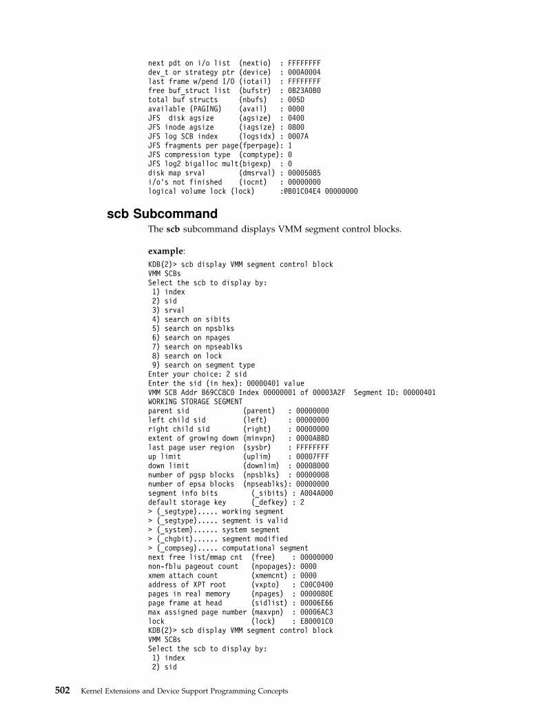
next pdt on i/o list (nextio) : FFFFFFFFdev_t or strategy ptr (device) : 000A0004last frame w/pend I/O (iotail) : FFFFFFFFfree buf_struct list (bufstr) : 0B23A0B0total buf structs (nbufs) : 005Davailable (PAGING) (avail) : 0000JFS disk agsize (agsize) : 0400JFS inode agsize (iagsize) : 0800JFS log SCB index (logsidx) : 0007AJFS fragments per page(fperpage): 1JFS compression type (comptype): 0JFS log2 bigalloc mult(bigexp) : 0disk map srval (dmsrval) : 00005085i/o's not finished (iocnt) : 00000000logical volume lock (lock) :@B01C04E4 00000000
scb SubcommandThe scb subcommand displays VMM segment control blocks.
example:
KDB(2)> scb display VMM segment control blockVMM SCBsSelect the scb to display by:1) index2) sid3) srval4) search on sibits5) search on npsblks6) search on npages7) search on npseablks8) search on lock9) search on segment typeEnter your choice: 2 sidEnter the sid (in hex): 00000401 valueVMM SCB Addr B69CC8C0 Index 00000001 of 00003A2F Segment ID: 00000401WORKING STORAGE SEGMENTparent sid (parent) : 00000000left child sid (left) : 00000000right child sid (right) : 00000000extent of growing down (minvpn) : 0000ABBDlast page user region (sysbr) : FFFFFFFFup limit (uplim) : 00007FFFdown limit (downlim) : 00008000number of pgsp blocks (npsblks) : 00000008number of epsa blocks (npseablks): 00000000segment info bits (_sibits) : A004A000default storage key (_defkey) : 2> (_segtype)..... working segment> (_segtype)..... segment is valid> (_system)...... system segment> (_chgbit)...... segment modified> (_compseg)..... computational segmentnext free list/mmap cnt (free) : 00000000non-fblu pageout count (npopages): 0000xmem attach count (xmemcnt) : 0000address of XPT root (vxpto) : C00C0400pages in real memory (npages) : 0000080Epage frame at head (sidlist) : 00006E66max assigned page number (maxvpn) : 00006AC3lock (lock) : E80001C0KDB(2)> scb display VMM segment control blockVMM SCBsSelect the scb to display by:1) index2) sid
502 Kernel Extensions and Device Support Programming Concepts

3) srval4) search on sibits5) search on npsblks6) search on npages7) search on npseablks8) search on lock9) search on segment typeEnter your choice: 8 search on lockFind all scbs currently locked
sidx 00000012 locked: 00044EEFsidx 00000D63 locked: 000412F7sidx 00000FB5 locked: 00044EEFsidx 00001072 locked: 000280E7sidx 000034B4 locked: 0002EC61
5 (dec) scb lockedKDB(2)> scb 1 display VMM segment control block by indexEnter the index (in hex): 000034B4 indexVMM SCB Addr B6AAC84C Index 000034B4 of 00003A2F Segment ID: 000064B4WORKING STORAGE SEGMENTparent sid (parent) : 00000000left child sid (left) : 00000000right child sid (right) : 00000000extent of growing down (minvpn) : 00010000last page user region (sysbr) : 00010000up limit (uplim) : 0000FFFFdown limit (downlim) : 00010000number of pgsp blocks (npsblks) : 0000000Anumber of epsa blocks (npseablks): 00000000segment info bits (_sibits) : A0002080default storage key (_defkey) : 2> (_segtype)..... working segment> (_segtype)..... segment is valid> (_compseg)..... computational segment> (_sparse)...... sparse segmentnext free list/mmap cnt (free) : 00000000non-fblu pageout count (npopages): 0000xmem attach count (xmemcnt) : 0000address of XPT root (vxpto) : C0699C00pages in real memory (npages) : 00000011page frame at head (sidlist) : 00004C5Cmax assigned page number (maxvpn) : 000001C1lock (lock) : E80955E0
pft SubcommandThe pft subcommand displays VMM page frame table.
example:
KDB(5)> pft display VMM page frameVMM PFTSelect the PFT entry to display by:1) page frame #2) h/w hash (sid,pno)3) s/w hash (sid,pno)4) search on swbits5) search on pincount6) search on xmemcnt7) scb list8) io listEnter your choice: 7 scb listEnter the sid (in hex): 00005555 sid valueVMM PFT Entry For Page Frame 0EB87 of 0FF67pte = B0155520, pvt = B203AE1C, pft = B3AC2950h/w hashed sid : 00005555 pno : 00000001 key : 1source sid : 00005555 pno : 00000001 key : 1> in use
Chapter 17. Debugging Tools 503

> on scb list> valid (h/w)> referenced (pft/pvt/pte): 0/0/1> modified (pft/pvt/pte): 0/0/0page number in scb (pagex) : 00000001disk block number (dblock) : 00000AC6next page on scb list (sidfwd) : 0000E682prev page on scb list (sidbwd) : FFFFFFFFfreefwd/waitlist (freefwd): 00000000freebwd/logage/pincnt (freebwd): 00000000out of order I/O (nonfifo): 0000next frame i/o list (nextio) : 00000000storage attributes (wimg) : 2xmem hide count (xmemcnt): 0next page on s/w hash (next) : FFFFFFFFList of alias entries (alist) : 0000FFFFindex in PDT (devid) : 0014VMM PFT Entry For Page Frame 0E682 of 0FF67pte = B01555F0, pvt = B2039A08, pft = B3AB3860h/w hashed sid : 00005555 pno : 00000002 key : 1source sid : 00005555 pno : 00000002 key : 1> in use> on scb list> valid (h/w)> referenced (pft/pvt/pte): 0/0/1> modified (pft/pvt/pte): 0/0/0page number in scb (pagex) : 00000002disk block number (dblock) : 00000AC7next page on scb list (sidfwd) : 0000EB7Bprev page on scb list (sidbwd) : 0000EB87freefwd/waitlist (freefwd): 00000000freebwd/logage/pincnt (freebwd): 00000000out of order I/O (nonfifo): 0000next frame i/o list (nextio) : 00000000storage attributes (wimg) : 2xmem hide count (xmemcnt): 0next page on s/w hash (next) : FFFFFFFFList of alias entries (alist) : 0000FFFFindex in PDT (devid) : 0014VMM PFT Entry For Page Frame 0EB7B of 0FF67pte = B0155558, pvt = B203ADEC, pft = B3AC2710h/w hashed sid : 00005555 pno : 00000000 key : 1source sid : 00005555 pno : 00000000 key : 1> in use> on scb list> valid (h/w)> referenced (pft/pvt/pte): 0/0/1> modified (pft/pvt/pte): 0/0/0page number in scb (pagex) : 00000000disk block number (dblock) : 00000AC5next page on scb list (sidfwd) : FFFFFFFFprev page on scb list (sidbwd) : 0000E682freefwd/waitlist (freefwd): 00000000freebwd/logage/pincnt (freebwd): 00000000out of order I/O (nonfifo): 0000next frame i/o list (nextio) : 00000000storage attributes (wimg) : 2xmem hide count (xmemcnt): 0next page on s/w hash (next) : FFFFFFFFList of alias entries (alist) : 0000FFFFindex in PDT (devid) : 0014Pages on SCB listnpages.......... 00000003on sidlist...... 00000003pageout_pagein.. 00000000free............ 00000000KDB(0)> pft 8 io list
504 Kernel Extensions and Device Support Programming Concepts

Enter the page frame number (in hex): 00002749 first page frameVMM PFT Entry For Page Frame 02749 of 0FF67pte = B00C9280, pvt = B2009D24, pft = B3875DB0h/w hashed sid : 0080324A pno : 00000000 key : 1source sid : 0000324A pno : 00000000 key : 1> page out> on scb list> ok to write to home> valid (h/w)> referenced (pft/pvt/pte): 0/1/0> modified (pft/pvt/pte): 1/1/0page number in scb (pagex) : 00000000disk block number (dblock) : 0000420Dnext page on scb list (sidfwd) : 0000EE94prev page on scb list (sidbwd) : 00002E11freefwd/waitlist (freefwd): E6096C00freebwd/logage/pincnt (freebwd): 00000000out of order I/O (nonfifo): 0001index in PDT (devid) : 0033next frame i/o list (nextio) : 000043EBstorage attributes (wimg) : 2xmem hide count (xmemcnt): 0next page on s/w hash (next) : FFFFFFFFList of alias entries (alist) : 0000FFFFVMM PFT Entry For Page Frame 043EB of 0FF67 next frame i/o listpte = B01580C0, pvt = B2010FAC, pft = B38CBC10h/w hashed sid : 008055FC pno : 000003FF key : 1source sid : 000055FC pno : 000003FF key : 1> page out> on scb list> ok to write to home> valid (h/w)> referenced (pft/pvt/pte): 0/1/0> modified (pft/pvt/pte): 1/1/0page number in scb (pagex) : 000003FFdisk block number (dblock) : 00044D47next page on scb list (sidfwd) : 00005364prev page on scb list (sidbwd) : 000043EBfreefwd/waitlist (freefwd): 00000000freebwd/logage/pincnt (freebwd): 00000000out of order I/O (nonfifo): 0001index in PDT (devid) : 0031next frame i/o list (nextio) : 00004405storage attributes (wimg) : 2xmem hide count (xmemcnt): 0next page on s/w hash (next) : 00002789List of alias entries (alist) : 0000FFFF...VMM PFT Entry For Page Frame 02E11 of 0FF67pte = B00C90C0, pvt = B200B844, pft = B388A330h/w hashed sid : 0080324A pno : 00000009 key : 1source sid : 0000324A pno : 00000009 key : 1> page out> on scb list> ok to write to home> valid (h/w)> referenced (pft/pvt/pte): 0/1/0> modified (pft/pvt/pte): 1/1/0page number in scb (pagex) : 00000009disk block number (dblock) : 000042C0next page on scb list (sidfwd) : 00002749prev page on scb list (sidbwd) : 00002FCBfreefwd/waitlist (freefwd): 00000000freebwd/logage/pincnt (freebwd): 00000000out of order I/O (nonfifo): 0001index in PDT (devid) : 0033next frame i/o list (nextio) : 00002749
Chapter 17. Debugging Tools 505

storage attributes (wimg) : 2xmem hide count (xmemcnt): 0next page on s/w hash (next) : FFFFFFFFList of alias entries (alist) : 0000FFFFPages on iolist...... 00000091
pte SubcommandThe pte subcommand displays VMM page table entries.
example:
KDB(1)> pte display VMM page table entryVMM PTESelect the PTE to display by:1) index2) sid,pno3) page frame4) PTE groupEnter your choice: 2 sid,pnoEnter the sid (in hex): 802 sid valueEnter the pno (in hex): 0 pno valuePTEX v SID h avpi RPN r c wimg pp004010 1 000802 0 00 007CD 1 1 0002 00KDB(1)> pte 4 display VMM page table groupEnter the sid (in hex): 802 sid valueEnter the pno (in hex): 0 pno valuePTEX v SID h avpi RPN r c wimg pp004010 1 000802 0 00 007CD 1 1 0002 00004011 1 000803 0 00 090FF 0 0 0002 03004012 0 000000 0 00 00000 0 0 0000 00004013 0 000000 0 00 00000 0 0 0000 00004014 0 000000 0 00 00000 0 0 0000 00004015 0 000000 0 00 00000 0 0 0000 00004016 0 000000 0 00 00000 0 0 0000 00004017 0 000000 0 00 00000 0 0 0000 00PTEX v SID h avpi RPN r c wimg pp03BFE8 1 00729E 0 01 0DC55 0 0 0002 0103BFE9 1 007659 0 00 07BC6 1 0 0002 0203BFEA 0 000000 0 00 00000 0 0 0000 0003BFEB 0 000000 0 00 00000 0 0 0000 0003BFEC 0 000000 0 00 00000 0 0 0000 0003BFED 0 000000 0 00 00000 0 0 0000 0003BFEE 0 000000 0 00 00000 0 0 0000 0003BFEF 0 000000 0 00 00000 0 0 0000 00
pta SubcommandThe pta subcommand displays VMM PTA segment.
example:
KDB(3)> pta ? display usageVMM PTA segment @ C0000000Usage: pta
pta -r[oot] [sid] to print XPT rootpta -d[blk] [sid] to print XPT direct blockspta -a[pm] [idx] to print Area Page Mappta -v[map] [idx] to print map blockspta -x[pt] xpt to print XPT fields
KDB(3)> pta display PTA informationVMM PTA segment @ C0000000pta_root....... @ C0000000 pta_hiapm...... : 00000200pta_vmapfree... : 00010FCB pta_usecount... : 0004D000pta_anchor[0].. : 00000107 pta_anchor[1].. : 00000000pta_anchor[2].. : 00000102 pta_anchor[3].. : 00000000pta_anchor[4].. : 00000000 pta_anchor[5].. : 00000000
506 Kernel Extensions and Device Support Programming Concepts
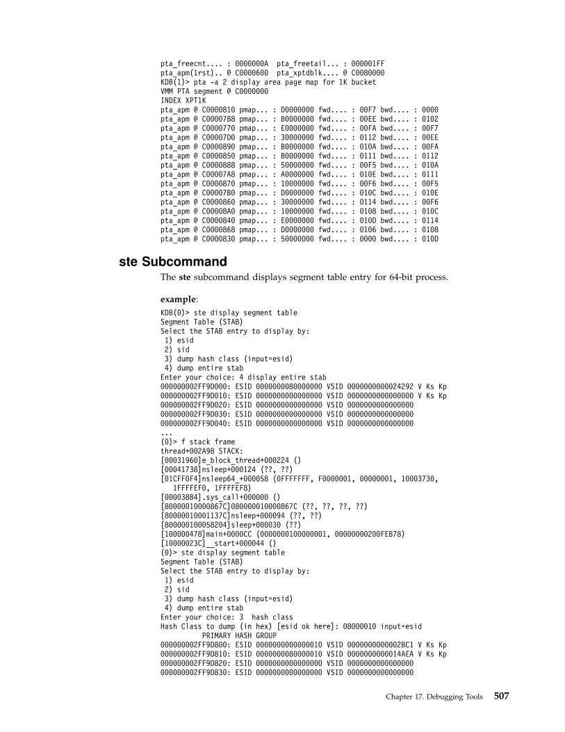
pta_freecnt.... : 0000000A pta_freetail... : 000001FFpta_apm(1rst).. @ C0000600 pta_xptdblk.... @ C0080000KDB(1)> pta -a 2 display area page map for 1K bucketVMM PTA segment @ C0000000INDEX XPT1Kpta_apm @ C0000810 pmap... : D0000000 fwd.... : 00F7 bwd.... : 0000pta_apm @ C00007B8 pmap... : B0000000 fwd.... : 00EE bwd.... : 0102pta_apm @ C0000770 pmap... : E0000000 fwd.... : 00FA bwd.... : 00F7pta_apm @ C00007D0 pmap... : 30000000 fwd.... : 0112 bwd.... : 00EEpta_apm @ C0000890 pmap... : B0000000 fwd.... : 010A bwd.... : 00FApta_apm @ C0000850 pmap... : B0000000 fwd.... : 0111 bwd.... : 0112pta_apm @ C0000888 pmap... : 50000000 fwd.... : 00F5 bwd.... : 010Apta_apm @ C00007A8 pmap... : A0000000 fwd.... : 010E bwd.... : 0111pta_apm @ C0000870 pmap... : 10000000 fwd.... : 00F6 bwd.... : 00F5pta_apm @ C00007B0 pmap... : D0000000 fwd.... : 010C bwd.... : 010Epta_apm @ C0000860 pmap... : 30000000 fwd.... : 0114 bwd.... : 00F6pta_apm @ C00008A0 pmap... : 10000000 fwd.... : 0108 bwd.... : 010Cpta_apm @ C0000840 pmap... : E0000000 fwd.... : 010D bwd.... : 0114pta_apm @ C0000868 pmap... : D0000000 fwd.... : 0106 bwd.... : 0108pta_apm @ C0000830 pmap... : 50000000 fwd.... : 0000 bwd.... : 010D
ste SubcommandThe ste subcommand displays segment table entry for 64-bit process.
example:
KDB(0)> ste display segment tableSegment Table (STAB)Select the STAB entry to display by:1) esid2) sid3) dump hash class (input=esid)4) dump entire stabEnter your choice: 4 display entire stab000000002FF9D000: ESID 0000000080000000 VSID 0000000000024292 V Ks Kp000000002FF9D010: ESID 0000000000000000 VSID 0000000000000000 V Ks Kp000000002FF9D020: ESID 0000000000000000 VSID 0000000000000000000000002FF9D030: ESID 0000000000000000 VSID 0000000000000000000000002FF9D040: ESID 0000000000000000 VSID 0000000000000000...(0)> f stack framethread+002A98 STACK:[00031960]e_block_thread+000224 ()[00041738]nsleep+000124 (??, ??)[01CFF0F4]nsleep64_+000058 (0FFFFFFF, F0000001, 00000001, 10003730,
1FFFFEF0, 1FFFFEF8)[000038B4].sys_call+000000 ()[80000010000867C]080000010000867C (??, ??, ??, ??)[80000010001137C]nsleep+000094 (??, ??)[800000100058204]sleep+000030 (??)[100000478]main+0000CC (0000000100000001, 00000000200FEB78)[10000023C]__start+000044 ()(0)> ste display segment tableSegment Table (STAB)Select the STAB entry to display by:1) esid2) sid3) dump hash class (input=esid)4) dump entire stabEnter your choice: 3 hash classHash Class to dump (in hex) [esid ok here]: 08000010 input=esid
PRIMARY HASH GROUP000000002FF9D800: ESID 0000000000000010 VSID 0000000000002BC1 V Ks Kp000000002FF9D810: ESID 0000000080000010 VSID 0000000000014AEA V Ks Kp000000002FF9D820: ESID 0000000000000000 VSID 0000000000000000000000002FF9D830: ESID 0000000000000000 VSID 0000000000000000
Chapter 17. Debugging Tools 507

000000002FF9D840: ESID 0000000000000000 VSID 0000000000000000000000002FF9D850: ESID 0000000000000000 VSID 0000000000000000000000002FF9D860: ESID 0000000000000000 VSID 0000000000000000000000002FF9D870: ESID 0000000000000000 VSID 0000000000000000
SECONDARY HASH GROUP000000002FF9D780: ESID 0000000000000000 VSID 0000000000000000000000002FF9D790: ESID 0000000000000000 VSID 0000000000000000000000002FF9D7A0: ESID 0000000000000000 VSID 0000000000000000000000002FF9D7B0: ESID 0000000000000000 VSID 0000000000000000000000002FF9D7C0: ESID 0000000000000000 VSID 0000000000000000000000002FF9D7D0: ESID 0000000000000000 VSID 0000000000000000000000002FF9D7E0: ESID 0000000000000000 VSID 0000000000000000000000002FF9D7F0: ESID 0000000000000000 VSID 0000000000000000000000002FF9DFF0: ESID 0000000000000000 VSID 0000000000000000(0)> ste 1 display esid entry in segment tableEnter the esid (in hex): 0FFFFFFFF000000002FF9DF80: ESID 00000000FFFFFFFF VSID 00000000000325F9 V Ks Kp
sr64 SubcommandThe sr64 subcommand displays segment registers for 64-bit process.
example:
KDB(0)> sr64 ? display helpUsage: sr64 [-p pid] [esid] [size]KDB(0)> sr64 display all segment registersSR00000000: 60000000 SR00000002: 60002B45 SR0000000D: 6000614CSR00000010: 6000520A SR00000011: 6000636CSR8001000A: 60003B47SR80020014: 6000B356SR8FFFFFFF: 60000340SR90000000: 60001142SR9FFFFFFF: 60004148SRFFFFFFFF: 6000B336KDB(0)> sr64 11 display up to 16 SRs from 10Segment registers for address space of Pid: 000048CASR00000010: 6000E339 SR00000011: 6000B855KDB(0)> sr64 0 100 display up to 256 SRs from 0Segment registers for address space of Pid: 000048CASR00000000: 60000000 SR00000002: 60002B45 SR0000000D: 6000614CSR00000010: 6000520A SR00000011: 6000636C
segst64 SubcommandThe segst64 subcommand displays segment state for 64-bit process.
example:
KDB(0)> segst64 displaysnode base last nvalid sfwd sbwd00000000 00000003 FFFFFFFE 00000010 00000001 FFFFFFFFESID segstate segflag num_segs fno/shmp/srval/nsegsSR00000003>[ 0] SEG_AVAIL 00000000 0000000ASR0000000D>[ 1] SEG_OTHER 00000001 00000001SR0000000E>[ 2] SEG_AVAIL 00000000 00000001SR0000000F>[ 3] SEG_OTHER 00000001 00000001SR00000010>[ 4] SEG_TEXT 00000001 00000001SR00000011>[ 5] SEG_WORKING 00000001 00000000SR00000012>[ 6] SEG_AVAIL 00000000 8000FFF8SR8001000A>[ 7] SEG_WORKING 00000001 00000000SR8001000B>[ 8] SEG_AVAIL 00000000 00010009SR80020014>[ 9] SEG_WORKING 00000001 00000000SR80020015>[10] SEG_AVAIL 00000000 0FFDFFEASR8FFFFFFF>[11] SEG_WORKING 00000001 00000000SR90000000>[12] SEG_TEXT 00000001 00000001SR90000001>[13] SEG_AVAIL 00000000 0FFFFFFE
508 Kernel Extensions and Device Support Programming Concepts
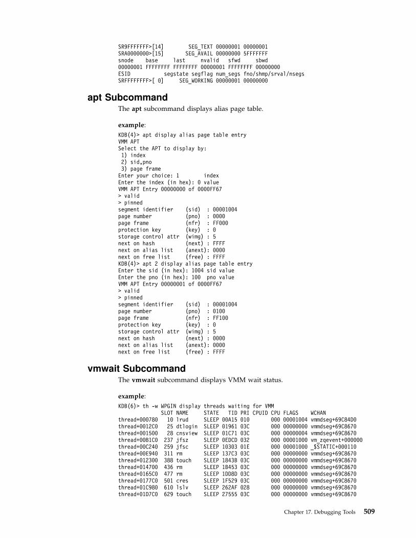
SR9FFFFFFF>[14] SEG_TEXT 00000001 00000001SRA0000000>[15] SEG_AVAIL 00000000 5FFFFFFFsnode base last nvalid sfwd sbwd00000001 FFFFFFFF FFFFFFFF 00000001 FFFFFFFF 00000000ESID segstate segflag num_segs fno/shmp/srval/nsegsSRFFFFFFFF>[ 0] SEG_WORKING 00000001 00000000
apt SubcommandThe apt subcommand displays alias page table.
example:
KDB(4)> apt display alias page table entryVMM APTSelect the APT to display by:1) index2) sid,pno3) page frameEnter your choice: 1 indexEnter the index (in hex): 0 valueVMM APT Entry 00000000 of 0000FF67> valid> pinnedsegment identifier (sid) : 00001004page number (pno) : 0000page frame (nfr) : FF000protection key (key) : 0storage control attr (wimg) : 5next on hash (next) : FFFFnext on alias list (anext): 0000next on free list (free) : FFFFKDB(4)> apt 2 display alias page table entryEnter the sid (in hex): 1004 sid valueEnter the pno (in hex): 100 pno valueVMM APT Entry 00000001 of 0000FF67> valid> pinnedsegment identifier (sid) : 00001004page number (pno) : 0100page frame (nfr) : FF100protection key (key) : 0storage control attr (wimg) : 5next on hash (next) : 0000next on alias list (anext): 0000next on free list (free) : FFFF
vmwait SubcommandThe vmwait subcommand displays VMM wait status.
example:
KDB(6)> th -w WPGIN display threads waiting for VMMSLOT NAME STATE TID PRI CPUID CPU FLAGS WCHAN
thread+000780 10 lrud SLEEP 00A15 010 000 00001004 vmmdseg+69C84D0thread+0012C0 25 dtlogin SLEEP 01961 03C 000 00000000 vmmdseg+69C8670thread+001500 28 cnsview SLEEP 01C71 03C 000 00000004 vmmdseg+69C8670thread+00B1C0 237 jfsz SLEEP 0EDCD 032 000 00001000 vm_zqevent+000000thread+00C240 259 jfsc SLEEP 10303 01E 000 00001000 _$STATIC+000110thread+00E940 311 rm SLEEP 137C3 03C 000 00000000 vmmdseg+69C8670thread+012300 388 touch SLEEP 1843B 03C 000 00000000 vmmdseg+69C8670thread+014700 436 rm SLEEP 1B453 03C 000 00000000 vmmdseg+69C8670thread+0165C0 477 rm SLEEP 1DD8D 03C 000 00000000 vmmdseg+69C8670thread+0177C0 501 cres SLEEP 1F529 03C 000 00000000 vmmdseg+69C8670thread+01C980 610 lslv SLEEP 262AF 028 000 00000000 vmmdseg+69C8670thread+01D7C0 629 touch SLEEP 27555 03C 000 00000000 vmmdseg+69C8670
Chapter 17. Debugging Tools 509
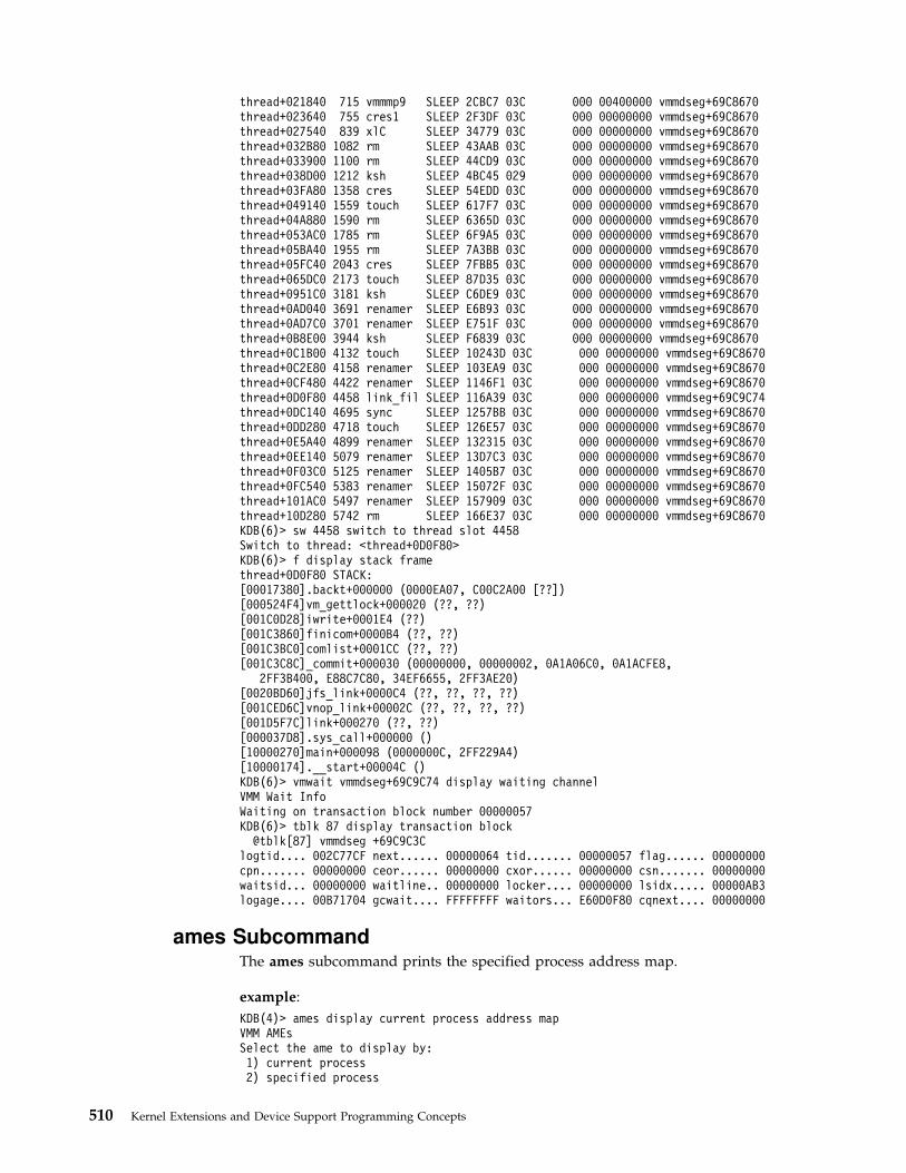
thread+021840 715 vmmmp9 SLEEP 2CBC7 03C 000 00400000 vmmdseg+69C8670thread+023640 755 cres1 SLEEP 2F3DF 03C 000 00000000 vmmdseg+69C8670thread+027540 839 xlC SLEEP 34779 03C 000 00000000 vmmdseg+69C8670thread+032B80 1082 rm SLEEP 43AAB 03C 000 00000000 vmmdseg+69C8670thread+033900 1100 rm SLEEP 44CD9 03C 000 00000000 vmmdseg+69C8670thread+038D00 1212 ksh SLEEP 4BC45 029 000 00000000 vmmdseg+69C8670thread+03FA80 1358 cres SLEEP 54EDD 03C 000 00000000 vmmdseg+69C8670thread+049140 1559 touch SLEEP 617F7 03C 000 00000000 vmmdseg+69C8670thread+04A880 1590 rm SLEEP 6365D 03C 000 00000000 vmmdseg+69C8670thread+053AC0 1785 rm SLEEP 6F9A5 03C 000 00000000 vmmdseg+69C8670thread+05BA40 1955 rm SLEEP 7A3BB 03C 000 00000000 vmmdseg+69C8670thread+05FC40 2043 cres SLEEP 7FBB5 03C 000 00000000 vmmdseg+69C8670thread+065DC0 2173 touch SLEEP 87D35 03C 000 00000000 vmmdseg+69C8670thread+0951C0 3181 ksh SLEEP C6DE9 03C 000 00000000 vmmdseg+69C8670thread+0AD040 3691 renamer SLEEP E6B93 03C 000 00000000 vmmdseg+69C8670thread+0AD7C0 3701 renamer SLEEP E751F 03C 000 00000000 vmmdseg+69C8670thread+0B8E00 3944 ksh SLEEP F6839 03C 000 00000000 vmmdseg+69C8670thread+0C1B00 4132 touch SLEEP 10243D 03C 000 00000000 vmmdseg+69C8670thread+0C2E80 4158 renamer SLEEP 103EA9 03C 000 00000000 vmmdseg+69C8670thread+0CF480 4422 renamer SLEEP 1146F1 03C 000 00000000 vmmdseg+69C8670thread+0D0F80 4458 link_fil SLEEP 116A39 03C 000 00000000 vmmdseg+69C9C74thread+0DC140 4695 sync SLEEP 1257BB 03C 000 00000000 vmmdseg+69C8670thread+0DD280 4718 touch SLEEP 126E57 03C 000 00000000 vmmdseg+69C8670thread+0E5A40 4899 renamer SLEEP 132315 03C 000 00000000 vmmdseg+69C8670thread+0EE140 5079 renamer SLEEP 13D7C3 03C 000 00000000 vmmdseg+69C8670thread+0F03C0 5125 renamer SLEEP 1405B7 03C 000 00000000 vmmdseg+69C8670thread+0FC540 5383 renamer SLEEP 15072F 03C 000 00000000 vmmdseg+69C8670thread+101AC0 5497 renamer SLEEP 157909 03C 000 00000000 vmmdseg+69C8670thread+10D280 5742 rm SLEEP 166E37 03C 000 00000000 vmmdseg+69C8670KDB(6)> sw 4458 switch to thread slot 4458Switch to thread: <thread+0D0F80>KDB(6)> f display stack framethread+0D0F80 STACK:[00017380].backt+000000 (0000EA07, C00C2A00 [??])[000524F4]vm_gettlock+000020 (??, ??)[001C0D28]iwrite+0001E4 (??)[001C3860]finicom+0000B4 (??, ??)[001C3BC0]comlist+0001CC (??, ??)[001C3C8C]_commit+000030 (00000000, 00000002, 0A1A06C0, 0A1ACFE8,
2FF3B400, E88C7C80, 34EF6655, 2FF3AE20)[0020BD60]jfs_link+0000C4 (??, ??, ??, ??)[001CED6C]vnop_link+00002C (??, ??, ??, ??)[001D5F7C]link+000270 (??, ??)[000037D8].sys_call+000000 ()[10000270]main+000098 (0000000C, 2FF229A4)[10000174].__start+00004C ()KDB(6)> vmwait vmmdseg+69C9C74 display waiting channelVMM Wait InfoWaiting on transaction block number 00000057KDB(6)> tblk 87 display transaction block
@tblk[87] vmmdseg +69C9C3Clogtid.... 002C77CF next...... 00000064 tid....... 00000057 flag...... 00000000cpn....... 00000000 ceor...... 00000000 cxor...... 00000000 csn....... 00000000waitsid... 00000000 waitline.. 00000000 locker.... 00000000 lsidx..... 00000AB3logage.... 00B71704 gcwait.... FFFFFFFF waitors... E60D0F80 cqnext.... 00000000
ames SubcommandThe ames subcommand prints the specified process address map.
example:
KDB(4)> ames display current process address mapVMM AMEsSelect the ame to display by:1) current process2) specified process
510 Kernel Extensions and Device Support Programming Concepts

Enter your choice: 1 current processVMM address map, address BADCD23Cprevious entry (vme_prev) : BADCC9FCnext entry (vme_next) : BADCC9FCminimum offset (min_offset) : 30000000maximum offset (max_offset) : D0000000number of entries (nentries) : 00000001size (size) : 00001000reference count (ref_count) : 00000001hint (hint) : BADCC9FCfirst free hint (first_free) : BADCC9FCentries pageable (entries_pageable): 00000000VMM map entry, address BADCC9FC> copy-on-write> needs-copyprevious entry (vme_prev) : BADCD23Cnext entry (vme_next) : BADCD23Cstart address (vme_start) : 60000000end address (vme_end) : 60001000object (vnode ptr) (object) : 09D7EB88page num in object (obj_pno) : 00000000cur protection (protection) : 00000003max protection (max_protection): 00000007inheritance (inheritance) : 00000001wired_count (wired_count) : 00000000source sid (source_sid) : 0000272Amapping sid (mapping_sid) : 000040B4paging sid (paging_sid) : 000029CEoriginal page num (orig_obj_pno) : 00000000xmem attach count (xmattach_count): 00000000KDB(4)> scb 2 display mapping sidEnter the sid (in hex): 000040B4 sid valueVMM SCB Addr B6A1384C Index 000010B4 of 00003A2F Segment ID: 000040B4MAPPING SEGMENTame start address (start): 60000000ame hint (ame) : BADCC9FCsegment info bits (_sibits) : 10000000default storage key (_defkey) : 0> (_segtype)..... mapping segment> (_segtype)..... segment is validnext free list/mmap cnt (free) : 00000001non-fblu pageout count (npopages): 0000xmem attach count (xmemcnt) : 0000address of XPT root (vxpto) : 00000000pages in real memory (npages) : 00000000page frame at head (sidlist) : FFFFFFFFmax assigned page number (maxvpn) : FFFFFFFFlock (lock) : E8038520
zproc SubcommandThe zproc subcommand prints the VMM zeroing kproc.
example:
KDB(1)> zproc display VMM zeroing kprocVMM zkproc pid = 63CA tid = 63FBCurrent queue info
Queue resides at 0x0009E3E8 with 10 elementsRequests 16800 processed 16800 failed 0Elements
sid pno npg pno npg0 - 007FFFFF FFFFFFFF 00000000 FFFFFFFF 000000001 - 007FFFFF FFFFFFFF 00000000 FFFFFFFF 000000002 - 007FFFFF FFFFFFFF 00000000 FFFFFFFF 000000003 - 007FFFFF FFFFFFFF 00000000 FFFFFFFF 000000004 - 007FFFFF FFFFFFFF 00000000 FFFFFFFF 00000000
Chapter 17. Debugging Tools 511

5 - 007FFFFF FFFFFFFF 00000000 FFFFFFFF 000000006 - 007FFFFF FFFFFFFF 00000000 FFFFFFFF 000000007 - 007FFFFF FFFFFFFF 00000000 FFFFFFFF 000000008 - 007FFFFF FFFFFFFF 00000000 FFFFFFFF 000000009 - 007FFFFF FFFFFFFF 00000000 FFFFFFFF 00000000
vmlog SubcommandThe vmlog subcommand prints the current VMM error log entry.
example:
KDB(0)> vmlog display VMM error log entryMost recent VMM errorlog entryError id = DSI_PROCException DSISR/ISISR = 40000000Exception srval = 007FFFFFException virt addr = FFFFFFFFException value = 0000000EKDB(0)> dr iar display current instructioniar : 01913DF001913DF0 lwz r0,0(r3) r0=00001030,0(r3)=FFFFFFFFKDB(0)>
vrld SubcommandThe vrld subcommand prints the VMM reload xlate table. This information is onlyused on SMP POWER PC machine, to prevent VMM reload dead-lock.
example:
KDB(0)> vrldfreepno: 0A, initobj: 0008DAA8, *initobj: FFFFFFFF[00] sid: 00000000, anch: 00
{00} spno:00000000, epno:00000097, nfr:00000000, next:01{01} spno:00000098, epno:000000AB, nfr:00000098, next:02{02} spno:FFFFFFFF, epno:000001F6, nfr:000001DD, next:03{03} spno:000001F7, epno:000001FA, nfr:000001F7, next:04{04} spno:0000038C, epno:000003E3, nfr:00000323, next:FF
[01] sid: 00000041, anch: 06{06} spno:00003400, epno:0000341F, nfr:000006EF, next:05{05} spno:00003800, epno:00003AFE, nfr:000003F0, next:08{08} spno:00006800, epno:00006800, nfr:0000037C, next:07{07} spno:00006820, epno:00006820, nfr:0000037B, next:09{09} spno:000069C0, epno:000069CC, nfr:0000072F, next:FF
[02] sid: FFFFFFFF, anch: FF[03] sid: FFFFFFFF, anch: FFKDB(0)>
ipc SubcommandThe ipc subcommand reports interprocess communication facility information.
example:
KDB(0)> ipcIPC infoSelect the display:1) Message Queues2) Shared Memory3) SemaphoresEnter your choice: 11) all msqid_ds2) select one msqid_ds3) struct msgEnter your choice: 1Message Queue id 00000000 @ 019E6988
512 Kernel Extensions and Device Support Programming Concepts

uid........... 00000000 gid........... 00000009cuid.......... 00000000 cgid.......... 00000009mode.......... 000083B0 seq........... 0000key........... 4107001C msg_first..... 00000000msg_last...... 00000000 msg_cbytes.... 00000000msg_qnum...... 00000000 msg_qbytes.... 0000FFFFmsg_lspid..... 00000000 msg_lrpid..... 00000000msg_stime..... 00000000 msg_rtime..... 00000000msg_ctime..... 3250C406 msg_rwait..... 0000561Dmsg_wwait..... FFFFFFFF msg_reqevents. 0000Message Queue id 00000001 @ 019E69D8uid........... 00000000 gid........... 00000000cuid.......... 00000000 cgid.......... 00000000mode.......... 000083B6 seq........... 0000key........... 77020916 msg_first..... 00000000msg_last...... 00000000 msg_cbytes.... 00000000msg_qnum...... 00000000 msg_qbytes.... 0000FFFFmsg_lspid..... 00000000 msg_lrpid..... 00000000msg_stime..... 00000000 msg_rtime..... 00000000msg_ctime..... 3250C40B msg_rwait..... 00006935msg_wwait..... FFFFFFFF msg_reqevents. 0000
lockanch SubcommandThe lka subcommand prints VMM lock anchor. The tblk subcommand prints thespecified transaction block.
example:
KDB(4)> lka display VMM lock anchorVMM LOCKANCH vmmdseg +69C8654nexttid................ : 003AB65Afreetid................ : 0000009Amaxtid................. : 000000B8lwptr.................. : BEDCD000freelock............... : 0000027Bmorelocks.............. : BEDD4000syncwait............... : 00000000tblkwait............... : 00000000freewait............... : 00000000
@tblk[1] vmmdseg +69C86BClogtid.... 003AB611 next...... 000002CF tid....... 00000001 flag...... 00000000cpn....... 00000000 ceor...... 00000000 cxor...... 00000000 csn....... 00000000waitsid... 00006A78 waitline.. 00000009 locker.... 00000015 lsidx..... 0000096Clogage.... 00B84FEC gcwait.... FFFFFFFF waitors... 00000000 cqnext.... 00000000
@tblk[2] vmmdseg +69C86FClogtid.... 003AB61A next...... 00000000 tid....... 00000002 flag...... 00000000cpn....... 00000000 ceor...... 00000000 cxor...... 00000000 csn....... 00000000waitsid... 00000000 waitline.. 00000000 locker.... 00000000 lsidx..... 0000096Clogage.... 00B861B8 gcwait.... FFFFFFFF waitors... 00000000 cqnext.... 00000000
@tblk[3] vmmdseg +69C873C tblk[3].cqnext vmmdseg +69C8D3Clogtid.... 003AB625 next...... 0000010D tid....... 00000003 flag...... 00000007cpn....... 00000B8B ceor...... 00000198 cxor...... 37A17C95 csn....... 00000342waitsid... 00000000 waitline.. 00000000 locker.... 00000000 lsidx..... 0000096Clogage.... 00B2AFC8 gcwait.... 00031825 waitors... E6012300 cqnext.... B69C8D3Cflag...... QUEUE READY COMMIT
@tblk[4] vmmdseg +69C877Clogtid.... 003AB649 next...... 00000301 tid....... 00000004 flag...... 00000000cpn....... 00000000 ceor...... 00000000 cxor...... 00000000 csn....... 00000000waitsid... 00000000 waitline.. 00000000 locker.... 00000000 lsidx..... 0000096Clogage.... 00B35FB8 gcwait.... FFFFFFFF waitors... 00000000 cqnext.... 00000000
@tblk[5] vmmdseg +69C87BClogtid.... 003AB418 next...... 00000000 tid....... 00000005 flag...... 00000000cpn....... 00000000 ceor...... 00000000 cxor...... 00000000 csn....... 00000000waitsid... 00007E7D waitline.. 00000014 locker.... 0000002D lsidx..... 0000096Clogage.... 00B46244 gcwait.... FFFFFFFF waitors... 00000000 cqnext.... 00000000
@tblk[6] vmmdseg +69C87FC
Chapter 17. Debugging Tools 513

logtid.... 003AB5AD next...... 0000003D tid....... 00000006 flag...... 00000000cpn....... 00000000 ceor...... 00000000 cxor...... 00000000 csn....... 00000000waitsid... 00007E7D waitline.. 0000001C locker.... 00000046 lsidx..... 0000096Clogage.... 00B2BF9C gcwait.... FFFFFFFF waitors... E603CE40 cqnext.... 00000000
@tblk[7] vmmdseg +69C883Clogtid.... 003AB1EC next...... 000001A3 tid....... 00000007 flag...... 00000000cpn....... 00000000 ceor...... 00000000 cxor...... 00000000 csn....... 00000000waitsid... 00000000 waitline.. 00000000 locker.... 00000000 lsidx..... 0000096Clogage.... 00B11F74 gcwait.... FFFFFFFF waitors... 00000000 cqnext.... 00000000(4)> more (|C to quit) ?
lockhash SubcommandThe lkh subcommand prints VMM lock hash list.
example:
KDB(4)> lkh display VMM lock hash listBUCKET HEAD COUNT
vmmdseg +69CC67C 1 00000144 3vmmdseg +69CC680 2 0000019D 3vmmdseg +69CC684 3 0000028E 2vmmdseg +69CC688 4 00000179 2vmmdseg +69CC68C 5 00000275 4vmmdseg +69CC690 6 00000249 1vmmdseg +69CC694 7 000000D4 2vmmdseg +69CC698 8 00000100 2vmmdseg +69CC69C 9 0000005E 2vmmdseg +69CC6A0 10 00000171 2vmmdseg +69CC6A4 11 00000245 2vmmdseg +69CC6AC 13 00000136 2vmmdseg +69CC6B4 15 000002F1 3vmmdseg +69CC6B8 16 00000048 1vmmdseg +69CC6BC 17 00000344 2vmmdseg +69CC6C4 19 000001E9 2vmmdseg +69CC6C8 20 0000021C 4vmmdseg +69CC6D0 22 00000239 1vmmdseg +69CC6D4 23 00000008 2vmmdseg +69CC6D8 24 00000304 2vmmdseg +69CC6DC 25 00000228 6vmmdseg +69CC6E8 28 0000008A 2vmmdseg +69CC6EC 29 000002F8 3vmmdseg +69CC6F0 30 0000005F 1vmmdseg +69CC6F4 31 000001FB 1vmmdseg +69CC6FC 33 00000107 1vmmdseg +69CC700 34 0000032A 2vmmdseg +69CC704 35 00000326 1vmmdseg +69CC708 36 0000006B 2vmmdseg +69CC70C 37 000002CF 1vmmdseg +69CC710 38 00000034 1vmmdseg +69CC718 40 000000CC 2vmmdseg +69CC71C 41 000001A4 1vmmdseg +69CC728 44 000000C5 2vmmdseg +69CC72C 45 000001C8 1vmmdseg +69CC730 46 00000075 3vmmdseg +69CC734 47 00000347 2vmmdseg +69CC738 48 000001C0 2vmmdseg +69CC73C 49 00000321 4vmmdseg +69CC740 50 0000033C 3vmmdseg +69CC744 51 00000201 3vmmdseg +69CC750 54 000002CE 3vmmdseg +69CC754 55 00000325 1vmmdseg +69CC758 56 00000263 2vmmdseg +69CC75C 57 0000014D 3vmmdseg +69CC760 58 000001FE 6...KDB(4)> lkh 58 display VMM lock hash list 58
514 Kernel Extensions and Device Support Programming Concepts
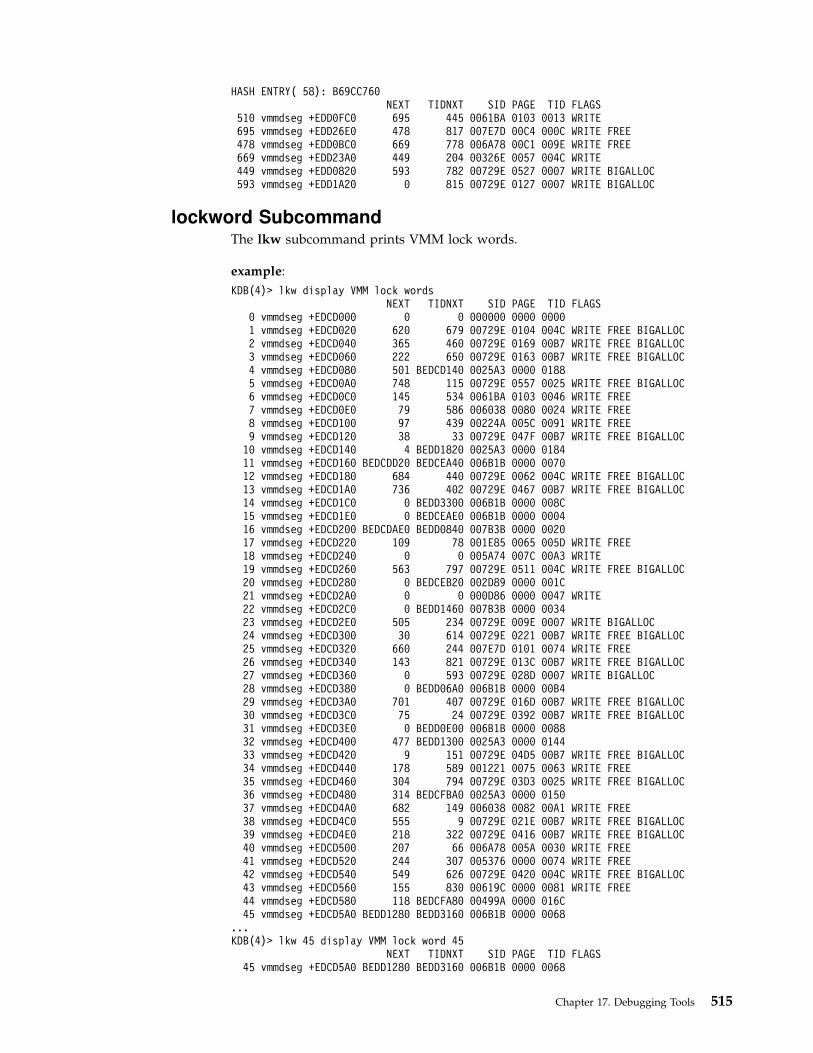
HASH ENTRY( 58): B69CC760NEXT TIDNXT SID PAGE TID FLAGS
510 vmmdseg +EDD0FC0 695 445 0061BA 0103 0013 WRITE695 vmmdseg +EDD26E0 478 817 007E7D 00C4 000C WRITE FREE478 vmmdseg +EDD0BC0 669 778 006A78 00C1 009E WRITE FREE669 vmmdseg +EDD23A0 449 204 00326E 0057 004C WRITE449 vmmdseg +EDD0820 593 782 00729E 0527 0007 WRITE BIGALLOC593 vmmdseg +EDD1A20 0 815 00729E 0127 0007 WRITE BIGALLOC
lockword SubcommandThe lkw subcommand prints VMM lock words.
example:
KDB(4)> lkw display VMM lock wordsNEXT TIDNXT SID PAGE TID FLAGS
0 vmmdseg +EDCD000 0 0 000000 0000 00001 vmmdseg +EDCD020 620 679 00729E 0104 004C WRITE FREE BIGALLOC2 vmmdseg +EDCD040 365 460 00729E 0169 00B7 WRITE FREE BIGALLOC3 vmmdseg +EDCD060 222 650 00729E 0163 00B7 WRITE FREE BIGALLOC4 vmmdseg +EDCD080 501 BEDCD140 0025A3 0000 01885 vmmdseg +EDCD0A0 748 115 00729E 0557 0025 WRITE FREE BIGALLOC6 vmmdseg +EDCD0C0 145 534 0061BA 0103 0046 WRITE FREE7 vmmdseg +EDCD0E0 79 586 006038 0080 0024 WRITE FREE8 vmmdseg +EDCD100 97 439 00224A 005C 0091 WRITE FREE9 vmmdseg +EDCD120 38 33 00729E 047F 00B7 WRITE FREE BIGALLOC10 vmmdseg +EDCD140 4 BEDD1820 0025A3 0000 018411 vmmdseg +EDCD160 BEDCDD20 BEDCEA40 006B1B 0000 007012 vmmdseg +EDCD180 684 440 00729E 0062 004C WRITE FREE BIGALLOC13 vmmdseg +EDCD1A0 736 402 00729E 0467 00B7 WRITE FREE BIGALLOC14 vmmdseg +EDCD1C0 0 BEDD3300 006B1B 0000 008C15 vmmdseg +EDCD1E0 0 BEDCEAE0 006B1B 0000 000416 vmmdseg +EDCD200 BEDCDAE0 BEDD0840 007B3B 0000 002017 vmmdseg +EDCD220 109 78 001E85 0065 005D WRITE FREE18 vmmdseg +EDCD240 0 0 005A74 007C 00A3 WRITE19 vmmdseg +EDCD260 563 797 00729E 0511 004C WRITE FREE BIGALLOC20 vmmdseg +EDCD280 0 BEDCEB20 002D89 0000 001C21 vmmdseg +EDCD2A0 0 0 000D86 0000 0047 WRITE22 vmmdseg +EDCD2C0 0 BEDD1460 007B3B 0000 003423 vmmdseg +EDCD2E0 505 234 00729E 009E 0007 WRITE BIGALLOC24 vmmdseg +EDCD300 30 614 00729E 0221 00B7 WRITE FREE BIGALLOC25 vmmdseg +EDCD320 660 244 007E7D 0101 0074 WRITE FREE26 vmmdseg +EDCD340 143 821 00729E 013C 00B7 WRITE FREE BIGALLOC27 vmmdseg +EDCD360 0 593 00729E 028D 0007 WRITE BIGALLOC28 vmmdseg +EDCD380 0 BEDD06A0 006B1B 0000 00B429 vmmdseg +EDCD3A0 701 407 00729E 016D 00B7 WRITE FREE BIGALLOC30 vmmdseg +EDCD3C0 75 24 00729E 0392 00B7 WRITE FREE BIGALLOC31 vmmdseg +EDCD3E0 0 BEDD0E00 006B1B 0000 008832 vmmdseg +EDCD400 477 BEDD1300 0025A3 0000 014433 vmmdseg +EDCD420 9 151 00729E 04D5 00B7 WRITE FREE BIGALLOC34 vmmdseg +EDCD440 178 589 001221 0075 0063 WRITE FREE35 vmmdseg +EDCD460 304 794 00729E 03D3 0025 WRITE FREE BIGALLOC36 vmmdseg +EDCD480 314 BEDCFBA0 0025A3 0000 015037 vmmdseg +EDCD4A0 682 149 006038 0082 00A1 WRITE FREE38 vmmdseg +EDCD4C0 555 9 00729E 021E 00B7 WRITE FREE BIGALLOC39 vmmdseg +EDCD4E0 218 322 00729E 0416 00B7 WRITE FREE BIGALLOC40 vmmdseg +EDCD500 207 66 006A78 005A 0030 WRITE FREE41 vmmdseg +EDCD520 244 307 005376 0000 0074 WRITE FREE42 vmmdseg +EDCD540 549 626 00729E 0420 004C WRITE FREE BIGALLOC43 vmmdseg +EDCD560 155 830 00619C 0000 0081 WRITE FREE44 vmmdseg +EDCD580 118 BEDCFA80 00499A 0000 016C45 vmmdseg +EDCD5A0 BEDD1280 BEDD3160 006B1B 0000 0068
...KDB(4)> lkw 45 display VMM lock word 45
NEXT TIDNXT SID PAGE TID FLAGS45 vmmdseg +EDCD5A0 BEDD1280 BEDD3160 006B1B 0000 0068
Chapter 17. Debugging Tools 515

bits........... 1000154A log............ 1000154Bhome........... 10001540 extmem......... 100015C0next........... BEDD1280 vmmdseg +EDD1280tidnxt......... BEDD3160 vmmdseg +EDD3160
NEXT TIDNXT SID PAGE TID FLAGS779 vmmdseg +EDD3160 BEDCE660 BEDD0C20 006B1B 0000 0064bits........... 10001480 log............ 10001483home........... 10001500 extmem......... 10001501next........... BEDCE660 vmmdseg +EDCE660tidnxt......... BEDD0C20 vmmdseg +EDD0C20
NEXT TIDNXT SID PAGE TID FLAGS481 vmmdseg +EDD0C20 BEDCFAA0 BEDD1FA0 006B1B 0000 0060bits........... 10001484 log............ 10001485home........... 10001486 extmem......... 10001482next........... BEDCFAA0 vmmdseg +EDCFAA0tidnxt......... BEDD1FA0 vmmdseg +EDD1FA0
NEXT TIDNXT SID PAGE TID FLAGS637 vmmdseg +EDD1FA0 BEDD2200 BEDD1220 006B1B 0000 0040bits........... 100012A3 log............ 100012A4home........... 10001299 extmem......... 1000131Cnext........... BEDD2200 vmmdseg +EDD2200tidnxt......... BEDD1220 vmmdseg +EDD1220
NEXT TIDNXT SID PAGE TID FLAGS529 vmmdseg +EDD1220 BEDCF980 BEDD31A0 006B1B 0000 0028bits........... 10001187 log............ 10001189home........... 100011A3 extmem......... 1000118Bnext........... BEDCF980 vmmdseg +EDCF980tidnxt......... BEDD31A0 vmmdseg +EDD31A0
NEXT TIDNXT SID PAGE TID FLAGS781 vmmdseg +EDD31A0 BEDCD2C0 BEDCFB40 006B1B 0000 0014bits........... 10001166 log............ 10001167home........... 1000115A extmem......... 10001157next........... BEDCD2C0 vmmdseg +EDCD2C0tidnxt......... BEDCFB40 vmmdseg +EDCFB40
NEXT TIDNXT SID PAGE TID FLAGS346 vmmdseg +EDCFB40 0 BEDCFFC0 006B1B 0000 0058bits........... 100013C1 log............ 100013C2home........... 100013C3 extmem......... 10001400tidnxt......... BEDCFFC0 vmmdseg +EDCFFC0
NEXT TIDNXT SID PAGE TID FLAGS382 vmmdseg +EDCFFC0 0 BEDD15C0 006B1B 0000 005Cbits........... 10001403 log............ 10001488home........... 10001489 extmem......... 1000148Atidnxt......... BEDD15C0 vmmdseg +EDD15C0
NEXT TIDNXT SID PAGE TID FLAGS558 vmmdseg +EDD15C0 0 BEDCFC40 006B1B 0000 0050(4)> more (|C to quit) ?bits........... 10001386 log............ 10001387home........... 10001389 extmem......... 1000138Ctidnxt......... BEDCFC40 vmmdseg +EDCFC40
NEXT TIDNXT SID PAGE TID FLAGS354 vmmdseg +EDCFC40 0 BEDD36E0 006B1B 0000 0054bits........... 1000138A log............ 1000138Bhome........... 10001382 extmem......... 10001385tidnxt......... BEDD36E0 vmmdseg +EDD36E0
NEXT TIDNXT SID PAGE TID FLAGS823 vmmdseg +EDD36E0 0 BEDD1D20 006B1B 0000 0010bits........... 10001548 log............ 10001546home........... 10001544 extmem......... 10001547tidnxt......... BEDD1D20 vmmdseg +EDD1D20
NEXT TIDNXT SID PAGE TID FLAGS617 vmmdseg +EDD1D20 0 BEDD2D40 006B1B 0000 0030bits........... 100011A7 log............ 100011FChome........... 100011FD extmem......... 100011E8tidnxt......... BEDD2D40 vmmdseg +EDD2D40
NEXT TIDNXT SID PAGE TID FLAGS746 vmmdseg +EDD2D40 0 BEDD16A0 006B1B 0000 000C
516 Kernel Extensions and Device Support Programming Concepts

bits........... 10001553 log............ 10001554home........... 10001545 extmem......... 10001541tidnxt......... BEDD16A0 vmmdseg +EDD16A0
NEXT TIDNXT SID PAGE TID FLAGS565 vmmdseg +EDD16A0 0 BEDD2C20 006B1B 0000 0020bits........... 10001159 log............ 10001141home........... 1000115D extmem......... 1000115Ctidnxt......... BEDD2C20 vmmdseg +EDD2C20
NEXT TIDNXT SID PAGE TID FLAGS737 vmmdseg +EDD2C20 0 BEDCDAE0 006B1B 0000 0048bits........... 1000130B log............ 1000131Dhome........... 1000131A extmem......... 1000131Btidnxt......... BEDCDAE0 vmmdseg +EDCDAE0
NEXT TIDNXT SID PAGE TID FLAGS87 vmmdseg +EDCDAE0 0 BEDD2E80 006B1B 0000 0000
bits........... 1000108F log............ 10001110home........... 1000114E extmem......... 1000114Ftidnxt......... BEDD2E80 vmmdseg +EDD2E80
NEXT TIDNXT SID PAGE TID FLAGS756 vmmdseg +EDD2E80 0 BEDD0960 006B1B 0000 004Cbits........... 1000132B log............ 1000132Chome........... 10001342 extmem......... 10001388tidnxt......... BEDD0960 vmmdseg +EDD0960
NEXT TIDNXT SID PAGE TID FLAGS459 vmmdseg +EDD0960 0 BEDD1140 006B1B 0000 0034bits........... 100011CF log............ 100011E2home........... 100011D0 extmem......... 100011D1tidnxt......... BEDD1140 vmmdseg +EDD1140(4)> more (|C to quit) ?
NEXT TIDNXT SID PAGE TID FLAGS522 vmmdseg +EDD1140 0 BEDCE580 006B1B 0000 0024bits........... 10001188 log............ 10001184home........... 10001186 extmem......... 1000118Atidnxt......... BEDCE580 vmmdseg +EDCE580
NEXT TIDNXT SID PAGE TID FLAGS172 vmmdseg +EDCE580 0 BEDCEC60 006B1B 0000 001Cbits........... 100011A0 log............ 1000119Ehome........... 100011F1 extmem......... 100011F2tidnxt......... BEDCEC60 vmmdseg +EDCEC60
NEXT TIDNXT SID PAGE TID FLAGS227 vmmdseg +EDCEC60 0 BEDCD1E0 006B1B 0000 0008bits........... 10001549 log............ 10001543home........... 10001542 extmem......... 10001552tidnxt......... BEDCD1E0 vmmdseg +EDCD1E0
NEXT TIDNXT SID PAGE TID FLAGS15 vmmdseg +EDCD1E0 0 BEDCEAE0 006B1B 0000 0004
bits........... 10001155 log............ 10001173home........... 10001140 extmem......... 10001156tidnxt......... BEDCEAE0 vmmdseg +EDCEAE0
NEXT TIDNXT SID PAGE TID FLAGS215 vmmdseg +EDCEAE0 0 BEDCE0E0 006B1B 0000 003Cbits........... 100011E4 log............ 100011E5home........... 10001297 extmem......... 10001298tidnxt......... BEDCE0E0 vmmdseg +EDCE0E0
NEXT TIDNXT SID PAGE TID FLAGS135 vmmdseg +EDCE0E0 0 BEDCE440 006B1B 0000 0044bits........... 10001318 log............ 1000133Bhome........... 1000133C extmem......... 1000130Ftidnxt......... BEDCE440 vmmdseg +EDCE440
NEXT TIDNXT SID PAGE TID FLAGS162 vmmdseg +EDCE440 0 BEDCF160 006B1B 0000 002Cbits........... 100011A4 log............ 100011A5home........... 100011A6 extmem......... 10001185tidnxt......... BEDCF160 vmmdseg +EDCF160
NEXT TIDNXT SID PAGE TID FLAGS267 vmmdseg +EDCF160 0 BEDCF2E0 006B1B 0000 0038bits........... 100011EA log............ 100011EB
Chapter 17. Debugging Tools 517

home........... 100011C8 extmem......... 100011D5tidnxt......... BEDCF2E0 vmmdseg +EDCF2E0
NEXT TIDNXT SID PAGE TID FLAGS279 vmmdseg +EDCF2E0 0 0 006B1B 0000 0018bits........... 10001117 log............ 10001168home........... 10001169 extmem......... 10001158KDB(4)>
vmdmap SubcommandThe vmdmap subcommand prints VMM disk maps. Argument could be a PDTindex. Default is all paging and file system disk map. To look at more, it isnecessary to initialize the segment register 13 with the corresponding srval.
example:
KDB(1)> vmdmap display VMM disk mapsPDT slot [0000] Vmdmap [D0000000] dmsrval [00000C03] <—- paging space 0mapsize................00007400 freecnt................00004D22agsize.................00000800 agcnt..................00000007totalags...............0000000F lastalloc..............00003384maptype................00000003 clsize.................00000001clmask.................00000080 [email protected] [email protected]@................D00001F4 [email protected] slot [0001] Vmdmap [D0800000] dmsrval [00000C03] <—- paging space 1mapsize................00005400 freecnt................00003CF6agsize.................00000800 agcnt..................00000007totalags...............0000000B lastalloc..............000047F4maptype................00000003 clsize.................00000001clmask.................00000080 [email protected] [email protected]@................D08001F4 [email protected] slot [0002] Vmdmap [D1000000] dmsrval [00000C03] <—- paging space 2mapsize................00005800 freecnt................0000418Cagsize.................00000800 agcnt..................00000007totalags...............0000000B lastalloc..............000047A8maptype................00000003 clsize.................00000001clmask.................00000080 [email protected] [email protected]@................D10001F4 [email protected] slot [0011] Vmdmap [D0000000] dmsrval [00003C2F] <—- file systemmapsize................00006400 freecnt................000057CCagsize.................00000800 agcnt..................00000007totalags...............0000000D lastalloc..............00001412maptype................00000001 clsize.................00000008clmask.................000000FF [email protected] [email protected]@................D00001F4 [email protected] slot [0013] Vmdmap [D0000000] dmsrval [00005455] <—- file systemmapsize................00000800 freecnt................0000030Aagsize.................00000400 agcnt..................00000002totalags...............00000002 lastalloc..............0000011Amaptype................00000001 clsize.................00000020clmask.................00000000 [email protected] [email protected]@................D00001F4 [email protected](1)> vmdmap 21 display VMM disk map slot 0x21PDT slot [0021] Vmdmap [D0000000] dmsrval [000075BC]mapsize................00000800 freecnt................000006B4agsize.................00000800 agcnt..................00000001totalags...............00000001 lastalloc..............00000060maptype................00000001 clsize.................00000008clmask.................000000FF [email protected] [email protected]@................D00001F4 [email protected]
518 Kernel Extensions and Device Support Programming Concepts

vmlocks SubcommandThe vl subcommand prints VMM spin locks.
For example:
KDB(1)> vl display VMM spin locksGLOBAL LOCKSpmap lock at @ 00000000 FREEvmker lock at @ 0009A1AC LOCKED by thread: 0039AEDpdt lock at @ B69C84D4 FREEvmap lock at @ B69C8514 FREEame lock at @ B69C8554 FREErpt lock at @ B69C8594 FREEalloc lock at @ B69C85D4 FREEapt lock at @ B69C8614 FREElw lock at @ B69C8678 FREESCOREBOARDscoreboard cpu 0 :hint.....................0000000000: empty01: empty02: empty03: empty04: empty05: empty06: empty07: emptyscoreboard cpu 1 :hint.....................0000000000: lock@ B6A31E60 lockword E804F38001: empty02: empty03: empty04: empty05: empty06: empty07: emptyscoreboard cpu 2 :hint.....................0000000200: lock@ B6A2851C lockword E8048B6001: empty02: empty03: empty04: empty05: empty06: empty07: emptyscoreboard cpu 3 :hint.....................0000000500: empty(1)> more (|C to quit) ?01: empty02: empty03: empty04: lock@ B6AB04D8 lockword E8096E2005: lock@ B69F2E54 lockword E802276006: empty07: emptyscoreboard cpu 4 :hint.....................0000000000: lock@ B6AAC380 lockword E809574001: empty02: empty03: empty04: empty05: empty
Chapter 17. Debugging Tools 519

06: empty07: emptyscoreboard cpu 5 :hint.....................0000000100: lock@ B6A7BBE0 lockword E805CC4001: lock@ B69CCD84 lockword E8000C8002: empty03: empty04: empty05: empty06: empty07: emptyscoreboard cpu 6 :hint.....................0000000000: empty01: empty02: empty03: empty04: empty05: empty06: empty07: emptyscoreboard cpu 7 :hint.....................0000000100: empty01: lock@ B6AA8FF8 lockword E807CA0002: empty03: empty04: empty05: empty06: empty07: emptyKDB(1)>
SMP Subcommands for the KDB Kernel Debugger and kdb Command
Note: The subcommands in this section are only valid for SMP machines.
KDB processor states are:
v running, outside kdb
v stopped, after a stop subcommand
v switched, after a cpu subcommand
v debug waiting, after a break point
v debug, inside kdb.
start and stop Subcommands
Note: This subcommand is only available within the kdb command; it is notincluded in the KDB Kernel Debugger.
The stop subcommand may be used to stop the specified processor. The startsubcommand may be used to start the specified processor. MPC is used to test anincoming kdb subcommand. When the processor is stopped, it is looping insideKDB. Stopped means that the processor does not go back to AIX.
ExampleKDB(1)> stop 0 stop processor 0KDB(1)> cpu display processors statuscpu 0 status VALID STOPPED action STOPcpu 1 status VALID DEBUG
520 Kernel Extensions and Device Support Programming Concepts
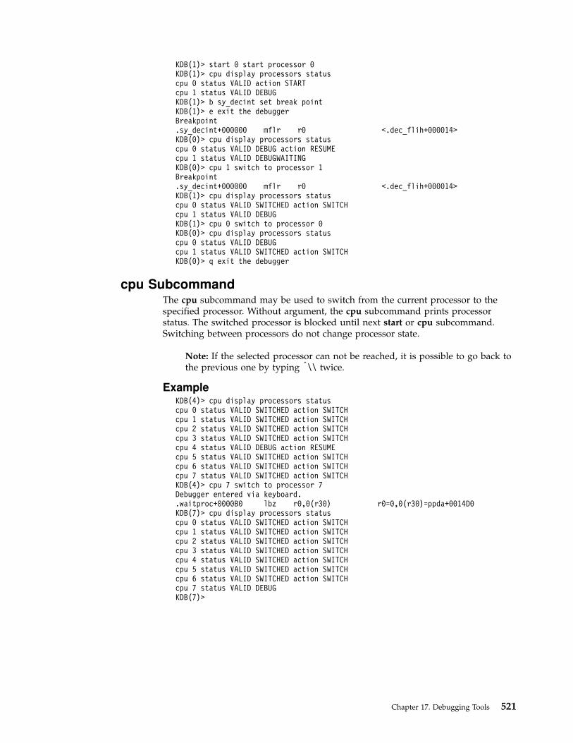
KDB(1)> start 0 start processor 0KDB(1)> cpu display processors statuscpu 0 status VALID action STARTcpu 1 status VALID DEBUGKDB(1)> b sy_decint set break pointKDB(1)> e exit the debuggerBreakpoint.sy_decint+000000 mflr r0 <.dec_flih+000014>KDB(0)> cpu display processors statuscpu 0 status VALID DEBUG action RESUMEcpu 1 status VALID DEBUGWAITINGKDB(0)> cpu 1 switch to processor 1Breakpoint.sy_decint+000000 mflr r0 <.dec_flih+000014>KDB(1)> cpu display processors statuscpu 0 status VALID SWITCHED action SWITCHcpu 1 status VALID DEBUGKDB(1)> cpu 0 switch to processor 0KDB(0)> cpu display processors statuscpu 0 status VALID DEBUGcpu 1 status VALID SWITCHED action SWITCHKDB(0)> q exit the debugger
cpu SubcommandThe cpu subcommand may be used to switch from the current processor to thespecified processor. Without argument, the cpu subcommand prints processorstatus. The switched processor is blocked until next start or cpu subcommand.Switching between processors do not change processor state.
Note: If the selected processor can not be reached, it is possible to go back tothe previous one by typing |\\ twice.
ExampleKDB(4)> cpu display processors statuscpu 0 status VALID SWITCHED action SWITCHcpu 1 status VALID SWITCHED action SWITCHcpu 2 status VALID SWITCHED action SWITCHcpu 3 status VALID SWITCHED action SWITCHcpu 4 status VALID DEBUG action RESUMEcpu 5 status VALID SWITCHED action SWITCHcpu 6 status VALID SWITCHED action SWITCHcpu 7 status VALID SWITCHED action SWITCHKDB(4)> cpu 7 switch to processor 7Debugger entered via keyboard..waitproc+0000B0 lbz r0,0(r30) r0=0,0(r30)=ppda+0014D0KDB(7)> cpu display processors statuscpu 0 status VALID SWITCHED action SWITCHcpu 1 status VALID SWITCHED action SWITCHcpu 2 status VALID SWITCHED action SWITCHcpu 3 status VALID SWITCHED action SWITCHcpu 4 status VALID SWITCHED action SWITCHcpu 5 status VALID SWITCHED action SWITCHcpu 6 status VALID SWITCHED action SWITCHcpu 7 status VALID DEBUGKDB(7)>
Chapter 17. Debugging Tools 521
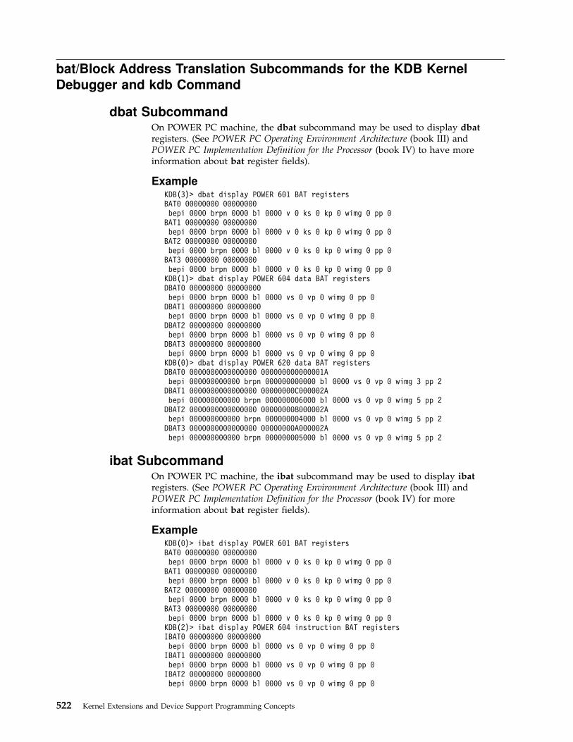
bat/Block Address Translation Subcommands for the KDB Kernel
Debugger and kdb Command
dbat SubcommandOn POWER PC machine, the dbat subcommand may be used to display dbatregisters. (See POWER PC Operating Environment Architecture (book III) andPOWER PC Implementation Definition for the Processor (book IV) to have moreinformation about bat register fields).
ExampleKDB(3)> dbat display POWER 601 BAT registersBAT0 00000000 00000000bepi 0000 brpn 0000 bl 0000 v 0 ks 0 kp 0 wimg 0 pp 0
BAT1 00000000 00000000bepi 0000 brpn 0000 bl 0000 v 0 ks 0 kp 0 wimg 0 pp 0
BAT2 00000000 00000000bepi 0000 brpn 0000 bl 0000 v 0 ks 0 kp 0 wimg 0 pp 0
BAT3 00000000 00000000bepi 0000 brpn 0000 bl 0000 v 0 ks 0 kp 0 wimg 0 pp 0
KDB(1)> dbat display POWER 604 data BAT registersDBAT0 00000000 00000000bepi 0000 brpn 0000 bl 0000 vs 0 vp 0 wimg 0 pp 0
DBAT1 00000000 00000000bepi 0000 brpn 0000 bl 0000 vs 0 vp 0 wimg 0 pp 0
DBAT2 00000000 00000000bepi 0000 brpn 0000 bl 0000 vs 0 vp 0 wimg 0 pp 0
DBAT3 00000000 00000000bepi 0000 brpn 0000 bl 0000 vs 0 vp 0 wimg 0 pp 0
KDB(0)> dbat display POWER 620 data BAT registersDBAT0 0000000000000000 000000000000001Abepi 000000000000 brpn 000000000000 bl 0000 vs 0 vp 0 wimg 3 pp 2
DBAT1 0000000000000000 00000000C000002Abepi 000000000000 brpn 000000006000 bl 0000 vs 0 vp 0 wimg 5 pp 2
DBAT2 0000000000000000 000000008000002Abepi 000000000000 brpn 000000004000 bl 0000 vs 0 vp 0 wimg 5 pp 2
DBAT3 0000000000000000 00000000A000002Abepi 000000000000 brpn 000000005000 bl 0000 vs 0 vp 0 wimg 5 pp 2
ibat SubcommandOn POWER PC machine, the ibat subcommand may be used to display ibatregisters. (See POWER PC Operating Environment Architecture (book III) andPOWER PC Implementation Definition for the Processor (book IV) for moreinformation about bat register fields).
ExampleKDB(0)> ibat display POWER 601 BAT registersBAT0 00000000 00000000bepi 0000 brpn 0000 bl 0000 v 0 ks 0 kp 0 wimg 0 pp 0
BAT1 00000000 00000000bepi 0000 brpn 0000 bl 0000 v 0 ks 0 kp 0 wimg 0 pp 0
BAT2 00000000 00000000bepi 0000 brpn 0000 bl 0000 v 0 ks 0 kp 0 wimg 0 pp 0
BAT3 00000000 00000000bepi 0000 brpn 0000 bl 0000 v 0 ks 0 kp 0 wimg 0 pp 0
KDB(2)> ibat display POWER 604 instruction BAT registersIBAT0 00000000 00000000bepi 0000 brpn 0000 bl 0000 vs 0 vp 0 wimg 0 pp 0
IBAT1 00000000 00000000bepi 0000 brpn 0000 bl 0000 vs 0 vp 0 wimg 0 pp 0
IBAT2 00000000 00000000bepi 0000 brpn 0000 bl 0000 vs 0 vp 0 wimg 0 pp 0
522 Kernel Extensions and Device Support Programming Concepts

IBAT3 00000000 00000000bepi 0000 brpn 0000 bl 0000 vs 0 vp 0 wimg 0 pp 0
KDB(0)> ibat display POWER 620 instruction BAT registersIBAT0 0000000000000000 0000000000000000bepi 000000000000 brpn 000000000000 bl 0000 vs 0 vp 0 wimg 0 pp 0
IBAT1 0000000000000000 0000000000000000bepi 000000000000 brpn 000000000000 bl 0000 vs 0 vp 0 wimg 0 pp 0
IBAT2 0000000000000000 0000000000000000bepi 000000000000 brpn 000000000000 bl 0000 vs 0 vp 0 wimg 0 pp 0
IBAT3 0000000000000000 0000000000000000bepi 000000000000 brpn 000000000000 bl 0000 vs 0 vp 0 wimg 0 pp 0
mdbat SubcommandEach dbat register may be altered by the mdbat subcommand. The processor databat register is altered immediately. KDB takes care of the valid bit, the word withvalid bit is set at last.
ExampleOn POWER 601 processorKDB(0)> dbat 2 display bat register 2BAT2: 00000000 00000000bepi 0000 brpn 0000 bl 0000 v 0 wimg 0 ks 0 kp 0 pp 0
KDB(0)> mdbat 2 alter bat register 2BAT register, enter <RC> twice to select BAT field, enter <.> to quitBAT2 upper 00000000 = <CR/LF>BAT2 lower 00000000 = <CR/LF>BAT field, enter <RC> to select field, enter <.> to quitBAT2.bepi: 00000000 = 00007FE0BAT2.brpn: 00000000 = 00007FE0BAT2.bl : 00000000 = 0000001FBAT2.v : 00000000 = 00000001BAT2.ks : 00000000 = 00000001BAT2.kp : 00000000 = <CR/LF>BAT2.wimg: 00000000 = 00000003BAT2.pp : 00000000 = 00000002BAT2: FFC0003A FFC0005Fbepi 7FE0 brpn 7FE0 bl 001F v 1 wimg 3 ks 1 kp 0 pp 2eaddr = FFC00000, paddr = FFC00000 size = 4096 KBytes
KDB(0)> mdbat 2 clear bat register 2BAT register, enter <RC> twice to select BAT field, enter <.> to quitBAT2 upper FFC0003A = 0BAT2 lower FFC0005F = 0BAT2 00000000 00000000bepi 0000 brpn 0000 bl 0000 v 0 wimg 0 ks 0 kp 0 pp 0
On POWER 604 processorKDB(0)> mdbat 2 alter bat register 2BAT register, enter <RC> twice to select BAT field, enter <.> to quitDBAT2 upper 00000000 =DBAT2 lower 00000000 =BAT field, enter <RC> to select field, enter <.> to quitDBAT2.bepi: 00000000 = 00007FE0DBAT2.brpn: 00000000 = 00007FE0DBAT2.bl : 00000000 = 0000001FDBAT2.vs : 00000000 = 00000001DBAT2.vp : 00000000 = <CR/LF>DBAT2.wimg: 00000000 = 00000003DBAT2.pp : 00000000 = 00000002DBAT2 FFC0007E FFC0001Abepi 7FE0 brpn 7FE0 bl 001F vs 1 vp 0 wimg 3 pp 2eaddr = FFC00000, paddr = FFC00000 size = 4096 KBytes [Supervisor state]
KDB(0)> mdbat 2 clear bat register 2BAT register, enter <RC> twice to select BAT field, enter <.> to quitDBAT2 upper FFC0007E = 0
Chapter 17. Debugging Tools 523

DBAT2 lower FFC0001A = 0DBAT2 00000000 00000000bepi 0000 brpn 0000 bl 0000 vs 0 vp 0 wimg 0 pp 0
mibat SubcommandEach ibat register may be altered by the mibat subcommand. The processorinstruction bat register is altered immediately.
ExampleOn POWER 601 processorKDB(0)> ibat 2 display bat register 2BAT2: 00000000 00000000bepi 0000 brpn 0000 bl 0000 v 0 wimg 0 ks 0 kp 0 pp 0
KDB(0)> mibat 2 alter bat register 2BAT register, enter <RC> twice to select BAT field, enter <.> to quitBAT2 upper 00000000 = <CR/LF>BAT2 lower 00000000 = <CR/LF>BAT field, enter <RC> to select field, enter <.> to quitBAT2.bepi: 00000000 = 00007FE0BAT2.brpn: 00000000 = 00007FE0BAT2.bl : 00000000 = 0000001FBAT2.v : 00000000 = 00000001BAT2.ks : 00000000 = 00000001BAT2.kp : 00000000 = <CR/LF>BAT2.wimg: 00000000 = 00000003BAT2.pp : 00000000 = 00000002BAT2: FFC0003A FFC0005Fbepi 7FE0 brpn 7FE0 bl 001F v 1 wimg 3 ks 1 kp 0 pp 2eaddr = FFC00000, paddr = FFC00000 size = 4096 KBytes
KDB(0)> mibat 2 clear bat register 2BAT register, enter <RC> twice to select BAT field, enter <.> to quitBAT2 upper FFC0003A = 0BAT2 lower FFC0005F = 0BAT2 00000000 00000000bepi 0000 brpn 0000 bl 0000 v 0 wimg 0 ks 0 kp 0 pp 0
On POWER 604 processorKDB(0)> mibat 2BAT register, enter <RC> twice to select BAT field, enter <.> to quitIBAT2 upper 00000000 = <CR/LF>IBAT2 lower 00000000 = <CR/LF>BAT field, enter <RC> to select field, enter <.> to quitIBAT2.bepi: 00000000 = <CR/LF>IBAT2.brpn: 00000000 = <CR/LF>IBAT2.bl : 00000000 = 3ffIBAT2.vs : 00000000 = 1IBAT2.vp : 00000000 = <CR/LF>IBAT2.wimg: 00000000 = 2IBAT2.pp : 00000000 = 2IBAT2 00000FFE 00000012bepi 0000 brpn 0000 bl 03FF vs 1 vp 0 wimg 2 pp 2eaddr = 00000000, paddr = 00000000 size = 131072 KBytes [Supervisor state]
btac/BRAT Subcommands for the KDB Kernel Debugger and kdb
Command
btac, cbtac, lbtac, lcbtac Subcommands
Note: This subcommand is only available within the kdb command; it is notincluded in the KDB Kernel Debugger.
524 Kernel Extensions and Device Support Programming Concepts

On POWER PC architecture, a hardware register may be used (called HID2 onPOWER 601) to enter KDB when a specified effective address is decoded. TheHID2 register holds the effective address, and the HID1 register specifies fullbranch target address compare and trap to address vector 0x1300 (0x2000 on 601).See PowerPC Implementation Definition for the 601-604-620 Processor (book IV) to havemore information. The btac subcommand may be used to stop when Branch TargetAddress Compare is true. The cbtac subcommand may be used to clear the lastbtac subcommand. This subcommand is global to all processors, each processormay have different address to compare with the local subcommands lbtac lcbtac.
It is possible to specify if the address is physical or virtual with -p or -v option.604 and 620 processors take care of the translation mode, and it is necessary tospecify which mode is used. By default KDB chooses the current state of themachine: if the subcommand is entered before VMM inititialisation, the address isphysical (real address), else virtual (effective address).
ExampleKDB(7)> btac open set BRAT on open functionKDB(7)> btac display current BRAT statusCPU 0: .open+000000 eaddr=001B5354 vsid=00000000 hit=0CPU 1: .open+000000 eaddr=001B5354 vsid=00000000 hit=0CPU 2: .open+000000 eaddr=001B5354 vsid=00000000 hit=0CPU 3: .open+000000 eaddr=001B5354 vsid=00000000 hit=0CPU 4: .open+000000 eaddr=001B5354 vsid=00000000 hit=0CPU 5: .open+000000 eaddr=001B5354 vsid=00000000 hit=0CPU 6: .open+000000 eaddr=001B5354 vsid=00000000 hit=0CPU 7: .open+000000 eaddr=001B5354 vsid=00000000 hit=0KDB(7)> e exit the debugger...Branch trap: 001B5354 <.open+000000>.sys_call+000000 bcctrl <.open>KDB(5)> btac display current BRAT statusCPU 0: .open+000000 eaddr=001B5354 vsid=00000000 hit=0CPU 1: .open+000000 eaddr=001B5354 vsid=00000000 hit=0CPU 2: .open+000000 eaddr=001B5354 vsid=00000000 hit=0CPU 3: .open+000000 eaddr=001B5354 vsid=00000000 hit=0CPU 4: .open+000000 eaddr=001B5354 vsid=00000000 hit=0CPU 5: .open+000000 eaddr=001B5354 vsid=00000000 hit=1CPU 6: .open+000000 eaddr=001B5354 vsid=00000000 hit=0CPU 7: .open+000000 eaddr=001B5354 vsid=00000000 hit=0KDB(5)> lbtac close set local BRAT on close functionKDB(5)> e exit the debugger...Branch trap: 001B5354 <.open+000000>.sys_call+000000 bcctrl <.open>KDB(7)> e exit the debugger...Branch trap: 00197D40 <.close+000000>.sys_call+000000 bcctrl <.close>KDB(5)> e exit the debugger...Branch trap: 001B5354 <.open+000000>.sys_call+000000 bcctrl <.open>KDB(6)> btac display current BRAT statusCPU 0: .open+000000 eaddr=001B5354 vsid=00000000 hit=0CPU 1: .open+000000 eaddr=001B5354 vsid=00000000 hit=0CPU 2: .open+000000 eaddr=001B5354 vsid=00000000 hit=0CPU 3: .open+000000 eaddr=001B5354 vsid=00000000 hit=0CPU 4: .open+000000 eaddr=001B5354 vsid=00000000 hit=0CPU 5: .close+000000 eaddr=00197D40 vsid=00000000 hit=1CPU 6: .open+000000 eaddr=001B5354 vsid=00000000 hit=1CPU 7: .open+000000 eaddr=001B5354 vsid=00000000 hit=1KDB(6)> cbtac reset all BRAT registers
Chapter 17. Debugging Tools 525

machdep Subcommands for the KDB Kernel Debugger and kdb
Command
reboot Subcommand
Note: This subcommand is only available within the kdb command; it is notincluded in the KDB Kernel Debugger.
The reboot subcommand may be used to reboot the machine. The soft rebootinterface is called (sr_slih(1)).
ExampleKDB(0)> reboot reboot the machineRebooting ...
Using the KDB Kernel Debug ProgramThe example files provide a demonstration kernel extension and a program toload, execute, and unload the extension. These programs may be compiled, linked,and executed as indicated in the following material. Note, to use these programs tofollow the examples you need a machine with a C compiler, a console, andrunning with a KDB kernel enabled for debugging. To use the KDB KernelDebugger you will need exclusive use of the machine.
Examples using the KDB Kernel Debugger with the demonstration programs areincluded in each of the following sections. The examples are shown in tables whichcontain two columns. The first column of the table contains an indication of thesystem prompt and the user input to perform each step. The second column ofeach table explains the function of the command and includes example output,where applicable. In the examples, since only the console is used, the demoprogram is switched between the background and the foreground as needed.
Example FilesThe files listed below are used in examples throughout this section.
v demo.c - Source program to load, execute, and unload a demonstration kernelextension.
v demokext.c - Source for a demonstration kernel extension
v demo.h - Include file used by demo.c and demokext.c
v demokext.exp - Export file for linking demokext
v comp_link - Example script to build demonstration program and kernelextension
To build the demonstration programs:
v Save each of the above files in a directory
v As the root user, execute the comp_link script
This script produces:
v An executable file demo
v An executable file demokext
v A list file demokext.lst
v A map file demokext.map
The following sections describe compilation and link options used in thecomp_link script in more detail and also cover using the map and list files.
526 Kernel Extensions and Device Support Programming Concepts
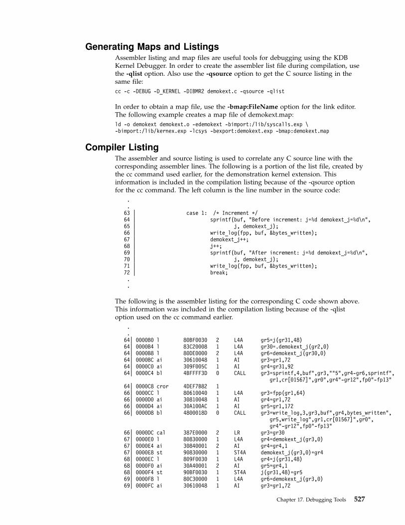
Generating Maps and ListingsAssembler listing and map files are useful tools for debugging using the KDBKernel Debugger. In order to create the assembler list file during compilation, usethe -qlist option. Also use the -qsource option to get the C source listing in thesame file:
cc -c -DEBUG -D_KERNEL -DIBMR2 demokext.c -qsource -qlist
In order to obtain a map file, use the -bmap:FileName option for the link editor.The following example creates a map file of demokext.map:
ld -o demokext demokext.o -edemokext -bimport:/lib/syscalls.exp \-bimport:/lib/kernex.exp -lcsys -bexport:demokext.exp -bmap:demokext.map
Compiler ListingThe assembler and source listing is used to correlate any C source line with thecorresponding assembler lines. The following is a portion of the list file, created bythe cc command used earlier, for the demonstration kernel extension. Thisinformation is included in the compilation listing because of the -qsource optionfor the cc command. The left column is the line number in the source code:
.
.63 | case 1: /* Increment */64 | sprintf(buf, "Before increment: j=%d demokext_j=%d\n",65 | j, demokext_j);66 | write_log(fpp, buf, &bytes_written);67 | demokext_j++;68 | j++;69 | sprintf(buf, "After increment: j=%d demokext_j=%d\n",70 | j, demokext_j);71 | write_log(fpp, buf, &bytes_written);72 | break;..
The following is the assembler listing for the corresponding C code shown above.This information was included in the compilation listing because of the -qlistoption used on the cc command earlier.
.
.64| 0000B0 l 80BF0030 2 L4A gr5=j(gr31,48)64| 0000B4 l 83C20008 1 L4A gr30=.demokext_j(gr2,0)64| 0000B8 l 80DE0000 2 L4A gr6=demokext_j(gr30,0)64| 0000BC ai 30610048 1 AI gr3=gr1,7264| 0000C0 ai 309F005C 1 AI gr4=gr31,9264| 0000C4 bl 4BFFFF3D 0 CALL gr3=sprintf,4,buf",gr3,""5",gr4-gr6,sprintf",
gr1,cr[01567]",gr0",gr4"-gr12",fp0"-fp13"64| 0000C8 cror 4DEF7B82 166| 0000CC l 80610040 1 L4A gr3=fpp(gr1,64)66| 0000D0 ai 30810048 1 AI gr4=gr1,7266| 0000D4 ai 30A100AC 1 AI gr5=gr1,17266| 0000D8 bl 4800018D 0 CALL gr3=write_log,3,gr3,buf",gr4,bytes_written",
gr5,write_log",gr1,cr[01567]",gr0",gr4"-gr12",fp0"-fp13"
66| 0000DC cal 387E0000 2 LR gr3=gr3067| 0000E0 l 80830000 1 L4A gr4=demokext_j(gr3,0)67| 0000E4 ai 30840001 2 AI gr4=gr4,167| 0000E8 st 90830000 1 ST4A demokext_j(gr3,0)=gr468| 0000EC l 809F0030 1 L4A gr4=j(gr31,48)68| 0000F0 ai 30A40001 2 AI gr5=gr4,168| 0000F4 st 90BF0030 1 ST4A j(gr31,48)=gr569| 0000F8 l 80C30000 1 L4A gr6=demokext_j(gr3,0)69| 0000FC ai 30610048 1 AI gr3=gr1,72
Chapter 17. Debugging Tools 527

69| 000100 ai 309F0084 1 AI gr4=gr31,13269| 000104 bl 4BFFFEFD 0 CALL gr3=sprintf,4,buf",gr3,""6",gr4-gr6,sprintf",
gr1,cr[01567]",gr0",gr4"-gr12",fp0"-fp13"69| 000108 cror 4DEF7B82 171| 00010C l 80610040 1 L4A gr3=fpp(gr1,64)71| 000110 ai 30810048 1 AI gr4=gr1,7271| 000114 ai 30A100AC 1 AI gr5=gr1,17271| 000118 bl 4800014D 0 CALL gr3=write_log,3,gr3,buf",gr4,bytes_written",
gr5,write_log",gr1,cr[01567]",gr0",gr4"-gr12",fp0"-fp13"
72| 00011C b 48000098 1 B CL.8,-1..
With both the assembler listing and the C source listing, the assembly instructionsassociated with each C statement may be found. As an example, consider the Csource line at line 67 of the demonstration kernel extension:
67 | demokext_j++;
The corresponding assembler instructions are:
67| 0000E0 l 80830000 1 L4A gr4=demokext_j(gr3,0)67| 0000E4 ai 30840001 2 AI gr4=gr4,167| 0000E8 st 90830000 1 ST4A demokext_j(gr3,0)=gr4
The offsets of these instructions within the demonstration kernel extension(demokext) are 0000E0, 0000E4, and 0000E8.
Map FileThe binder map file is a symbol map in address order format. Each symbol listedin the map file has a storage class (CL) and a type (TY) associated with it.
Storage classes correspond to the XMC_XX variables defined in the syms.h file.Each storage class belongs to one of the following section types:
.text Contains read-only data (instructions). Addresses listed in this section use thebeginning of the .text section as origin. The .text section can contain one of thefollowing storage class (CL) values:
DB Debug Table. Identifies a class of sections that has the same characteristicsas read only data.
GL Glue Code. Identifies a section that has the same characteristics as aprogram code. This type of section has code to interface with a routine inanother module. Part of the interface code requirement is to maintain TOCaddressability across the call.
PR Program Code. Identifies the sections that provide executable instructionsfor the module.
R0 Read Only Data. Identifies the sections that contain constants that are notmodified during execution.
TB Reserved.
TI Reserved.
XO Extended Op. Identifies a section of code that is to be treated as apseudo-machine instruction.
528 Kernel Extensions and Device Support Programming Concepts
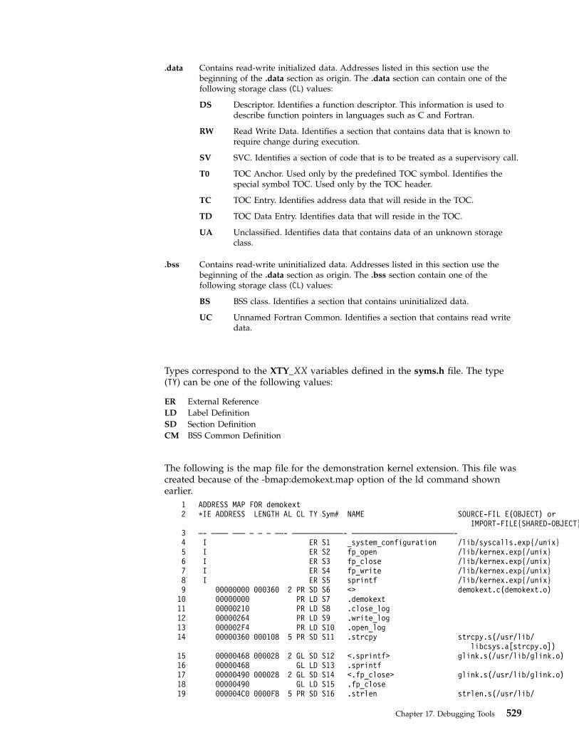
.data Contains read-write initialized data. Addresses listed in this section use thebeginning of the .data section as origin. The .data section can contain one of thefollowing storage class (CL) values:
DS Descriptor. Identifies a function descriptor. This information is used todescribe function pointers in languages such as C and Fortran.
RW Read Write Data. Identifies a section that contains data that is known torequire change during execution.
SV SVC. Identifies a section of code that is to be treated as a supervisory call.
T0 TOC Anchor. Used only by the predefined TOC symbol. Identifies thespecial symbol TOC. Used only by the TOC header.
TC TOC Entry. Identifies address data that will reside in the TOC.
TD TOC Data Entry. Identifies data that will reside in the TOC.
UA Unclassified. Identifies data that contains data of an unknown storageclass.
.bss Contains read-write uninitialized data. Addresses listed in this section use thebeginning of the .data section as origin. The .bss section contain one of thefollowing storage class (CL) values:
BS BSS class. Identifies a section that contains uninitialized data.
UC Unnamed Fortran Common. Identifies a section that contains read writedata.
Types correspond to the XTY_XX variables defined in the syms.h file. The type(TY) can be one of the following values:
ER External Reference
LD Label Definition
SD Section Definition
CM BSS Common Definition
The following is the map file for the demonstration kernel extension. This file wascreated because of the -bmap:demokext.map option of the ld command shownearlier.
1 ADDRESS MAP FOR demokext2 *IE ADDRESS LENGTH AL CL TY Sym# NAME SOURCE-FIL E(OBJECT) or
IMPORT-FILE{SHARED-OBJECT}3 —- ———— ——— — — — ——- ————————————- ————————————————————————-4 I ER S1 _system_configuration /lib/syscalls.exp{/unix}5 I ER S2 fp_open /lib/kernex.exp{/unix}6 I ER S3 fp_close /lib/kernex.exp{/unix}7 I ER S4 fp_write /lib/kernex.exp{/unix}8 I ER S5 sprintf /lib/kernex.exp{/unix}9 00000000 000360 2 PR SD S6 <> demokext.c(demokext.o)
10 00000000 PR LD S7 .demokext11 00000210 PR LD S8 .close_log12 00000264 PR LD S9 .write_log13 000002F4 PR LD S10 .open_log14 00000360 000108 5 PR SD S11 .strcpy strcpy.s(/usr/lib/
libcsys.a[strcpy.o])15 00000468 000028 2 GL SD S12 <.sprintf> glink.s(/usr/lib/glink.o)16 00000468 GL LD S13 .sprintf17 00000490 000028 2 GL SD S14 <.fp_close> glink.s(/usr/lib/glink.o)18 00000490 GL LD S15 .fp_close19 000004C0 0000F8 5 PR SD S16 .strlen strlen.s(/usr/lib/
Chapter 17. Debugging Tools 529

libcsys.a[strlen.o])20 000005B8 000028 2 GL SD S17 <.fp_write> glink.s(/usr/lib/glink.o)21 000005B8 GL LD S18 .fp_write22 000005E0 000028 2 GL SD S19 <.fp_open> glink.s(/usr/lib/glink.o)23 000005E0 GL LD S20 .fp_open24 00000000 0000F9 3 RW SD S21 <_$STATIC> demokext.c(demokext.o)25 E 000000FC 000004 2 RW SD S22 demokext_j demokext.c(demokext.o)26 * 00000100 00000C 2 DS SD S23 demokext demokext.c(demokext.o)27 0000010C 000000 2 T0 SD S24 <TOC>28 0000010C 000004 2 TC SD S25 <_$STATIC>29 00000110 000004 2 TC SD S26 <_system_configuration>30 00000114 000004 2 TC SD S27 <demokext_j>31 00000118 000004 2 TC SD S28 <sprintf>32 0000011C 000004 2 TC SD S29 <fp_close>33 00000120 000004 2 TC SD S30 <fp_write>34 00000124 000004 2 TC SD S31 <fp_open>
In the above map file, the .data section starts at the statement for line 24:
24 00000000 0000F9 3 RW SD S21 <_$STATIC> demokext.c(demokext.o)
The TOC (Table Of Contents) starts at the statement for line 27:
27 0000010C 000000 2 T0 SD S24 <TOC>
Setting BreakpointsSetting a breakpoint is essential for debugging kernel extensions. To set abreakpoint, use the following sequence of steps:
1. Locate the assembler instruction corresponding to the C statement.
2. Get the offset of the assembler instruction from the listing.
3. Locate the address where the kernel extension is loaded.
4. Add the address of the assembler instruction to the address where kernelextension is loaded.
5. Set the breakpoint with the KDB b (break) subcommand.
The process of locating the assembler instruction and getting its offset is explainedin the previous section. To continue with the demokext example, we will set abreak at the C source line 67, which increments the variable demokext_j. The list fileindicates that this line starts at an offset of 0xE0. So the next step is to determinethe address where the kernel extension is loaded.
Determine the Location of your Kernel ExtensionTo determine the address at which a kernel extension has been loaded, use thefollowing procedure. First, find the load point (the entry point) of the executablekernel extension. This is a label supplied with the -e option for the ld command. Inthe example this is the demokext routine.
Use one of the following methods to locate the address of this load point and set abreakpoint at the appropriate offset from this point.
v Method 1
Normally, with the KDB Kernel Debugger a breakpoint may be set directly byusing the b subcommand in conjunction with the routine name and the offset.For example, b demokext+4 will set a break at the instruction 4 bytes from thebeginning of the demokext routine.
v Method 2
The KDB lke subcommand displays a list of loaded kernel extensions. To findthe address of the modules for a particular extension use the KDB subcommandlke entry_number, where entry_number is the extension number of interest. In
530 Kernel Extensions and Device Support Programming Concepts

the displayed data is a list of Process Trace Backs which shows the beginningaddresses of routines contained in the extension.
v Method 3
If the kernel extension is not stripped the KDB Kernel Debugger may be used tolocate the address of the load point by name. For example the subcommand nmdemokext returns the address of the demokext routine after it is loaded. Thisaddress may then be used to set a breakpoint.
v Method 4
Another method to locate the address of the entry point for a kernel extension isto use the value of the kmid pointer returned by the sysconfig(SYS_KLOAD)subroutine when the kernel extension is loaded. The kmid pointer points to theaddress of the load point routine. Hence to get the address of the load point,print the kmid value during the sysconfig call from the configuration method;in the current example, this is the demo.c module. Then go into the KDB KernelDebugger and display the value pointed to by kmid.
v Method 5
If the kernel extension is a device driver, use the KDB devsw subcommand tolocate the desired address. The devsw subcommand lists all the functionaddresses for the device driver (that are in the dev switch table). Usually theconfig routine will be the load point routine.
MAJ#010 OPEN CLOSE READ WRITE0123DE04 0123DC04 0123DB20 0123DA3CIOCTL STRATEGY TTY SELECT0123D090 01244DF0 00000000 00059774CONFIG PRINT DUMP MPX0123E8C8 00059774 00059774 00059774REVOKE DSDPTR SELPTR OPTS00059774 00000000 00000000 00000002
The following provides examples of each of the above methods using the demoand demokext routines compiled earlier. Note, the following must be run as theroot user. For this example, assume that a break is to be set at line 67, which hasan offset from the beginning of demokext of 0xE0.
Prompt and Console Input Function and Example Output
Load the demokext kernel extension
$ ./demo Run the demo program, this loads the demokext extension. Note, the value printed forkmid, this is used later in this example.
$ <CTRL-Z> Stop the demo program.
$ bg Put the demo program in the background.
$ <CTRL-\> Activate KDB, use the appropriate key sequence for your configuration. You shouldhave a KDB prompt on completion of this step.
Set a breakpoint using Method 1
KDB(0)> b demokext+E0 Set a breakpoint using the symbol demokext. This is the easiest and most commonway of setting a breakpoint within KDB. KDB responds with an indication of theaddress where the break is set.
KDB(0)> b List all breakpoints. KDB displays a list of all breakpoints currently active.
KDB(0)> ca This clears all breakpoints
KDB(0)> b List all breakpoints. KDB indicates there are no active breakpoints.
Set a breakpoint using Method 2
Chapter 17. Debugging Tools 531
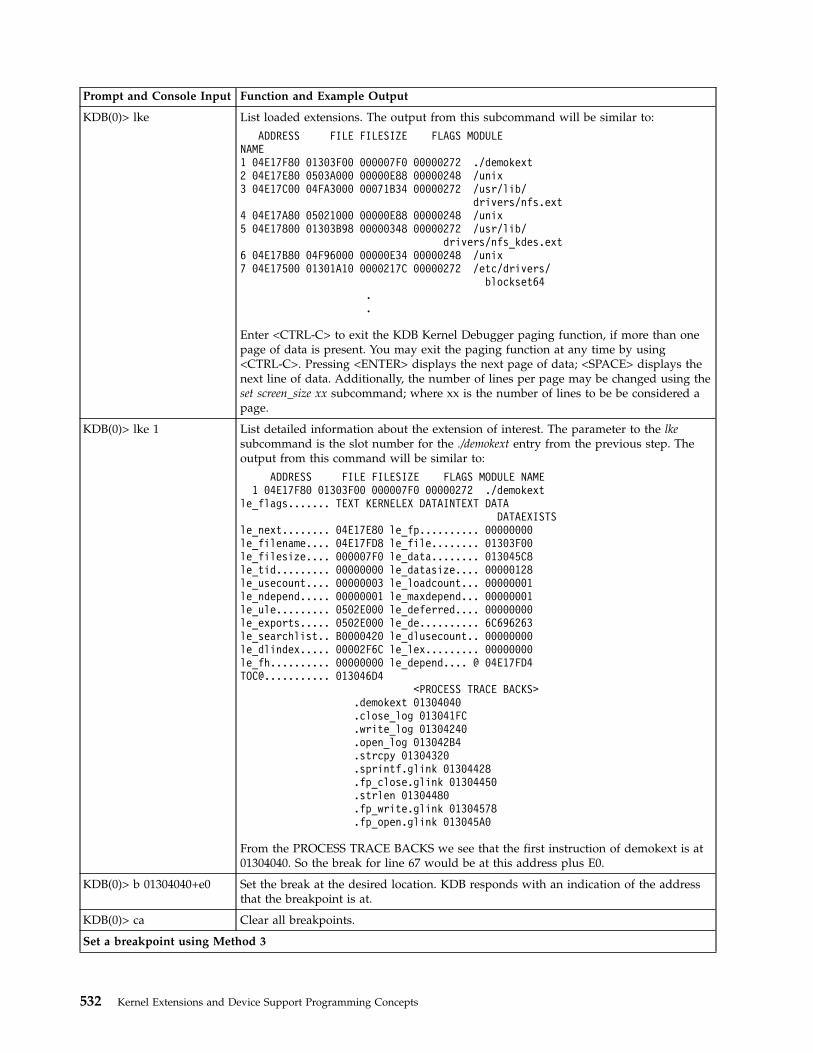
Prompt and Console Input Function and Example Output
KDB(0)> lke List loaded extensions. The output from this subcommand will be similar to:
ADDRESS FILE FILESIZE FLAGS MODULENAME1 04E17F80 01303F00 000007F0 00000272 ./demokext2 04E17E80 0503A000 00000E88 00000248 /unix3 04E17C00 04FA3000 00071B34 00000272 /usr/lib/
drivers/nfs.ext4 04E17A80 05021000 00000E88 00000248 /unix5 04E17800 01303B98 00000348 00000272 /usr/lib/
drivers/nfs_kdes.ext6 04E17B80 04F96000 00000E34 00000248 /unix7 04E17500 01301A10 0000217C 00000272 /etc/drivers/
blockset64..
Enter <CTRL-C> to exit the KDB Kernel Debugger paging function, if more than onepage of data is present. You may exit the paging function at any time by using<CTRL-C>. Pressing <ENTER> displays the next page of data; <SPACE> displays thenext line of data. Additionally, the number of lines per page may be changed using theset screen_size xx subcommand; where xx is the number of lines to be be considered apage.
KDB(0)> lke 1 List detailed information about the extension of interest. The parameter to the lkesubcommand is the slot number for the ./demokext entry from the previous step. Theoutput from this command will be similar to:
ADDRESS FILE FILESIZE FLAGS MODULE NAME1 04E17F80 01303F00 000007F0 00000272 ./demokext
le_flags....... TEXT KERNELEX DATAINTEXT DATADATAEXISTS
le_next........ 04E17E80 le_fp.......... 00000000le_filename.... 04E17FD8 le_file........ 01303F00le_filesize.... 000007F0 le_data........ 013045C8le_tid......... 00000000 le_datasize.... 00000128le_usecount.... 00000003 le_loadcount... 00000001le_ndepend..... 00000001 le_maxdepend... 00000001le_ule......... 0502E000 le_deferred.... 00000000le_exports..... 0502E000 le_de.......... 6C696263le_searchlist.. B0000420 le_dlusecount.. 00000000le_dlindex..... 00002F6C le_lex......... 00000000le_fh.......... 00000000 le_depend.... @ 04E17FD4TOC@........... 013046D4
<PROCESS TRACE BACKS>.demokext 01304040.close_log 013041FC.write_log 01304240.open_log 013042B4.strcpy 01304320.sprintf.glink 01304428.fp_close.glink 01304450.strlen 01304480.fp_write.glink 01304578.fp_open.glink 013045A0
From the PROCESS TRACE BACKS we see that the first instruction of demokext is at01304040. So the break for line 67 would be at this address plus E0.
KDB(0)> b 01304040+e0 Set the break at the desired location. KDB responds with an indication of the addressthat the breakpoint is at.
KDB(0)> ca Clear all breakpoints.
Set a breakpoint using Method 3
532 Kernel Extensions and Device Support Programming Concepts

Prompt and Console Input Function and Example Output
KDB(0)> nm demokext This translates a symbol to an effective address. The output from this subcommandwill be similar to:
Symbol Address : 01304040TOC Address : 013046D4
The value of the symbol demokext is the address of the first instruction of thedemokext routine. So this value can be used to set a breakpoint, just as in the previousexample.
KDB(0)> b 01304040+e0 Set the break at the desired location. KDB responds with an indication of the addressthat the breakpoint is at.
KDB(0)> dw 01304040+e0 Display the word at the breakpoint. KDB will respond with something similar to:
01304120: 80830000 30840001 90830000 809F0030....0..........0
This can then be checked against the assembly code in the listing to verify that thebreak is set at the correct location.
KDB(0)> ca Clear all breakpoints.
Set a breakpoint using Method 4
KDB(0)> dw 1304748 Display the memory at the address returned as the kmid from the sysconfig routine atthe beginning of this example. KDB responds with something similar to:
demokext+000000: 01304040 01304754 0000000001304648 .0@@.0GT.....0FH
The first word of data displayed is the address of the first instruction of the demokextroutine. Note, the data displayed is at the location demokext+000000. This correspondsto line 26 of the map presented earlier. However, the most important thing to note isthat demokext+000000 and .demokext+000000 are not the same address. The location.demokext+000000 corresponds to line 10 of the map and is the address of the firstinstruction for the demokext routine.
KDB(0)> b 01304040+e0 Set the break at the location indicated from the previous command plus the offset toget to line 67. KDB responds with an indication of the address that the breakpoint isat.
ca Clear all breakpoints.
Set a breakpoint using Method 5
KDB(0)> devsw 1 Display the device switch table for the first entry. Note, the demonstration programthat is being used is not a device driver; so this example just uses the addresses of thefirst device driver in the device switch table and is not related in any way to thedemonstration program. The KDB devsw command displays data similar to:
Slot address 50006040MAJ#001OPEN CLOSE READ WRITE.syopen .nulldev .syread .sywriteIOCTL STRATEGY TTY SELECT.syioctl .nodev 00000000 .syselectCONFIG PRINT DUMP MPX.nodev .nodev .nodev .nodevREVOKE DSDPTR SELPTR OPTS.nodev 00000000 00000000 00000012
KDB(0)> b .syopen+20 Set a breakpoint at an offset of 0x20 from the beginning of the open routine for thefirst device driver in the device switch table. Note, KDB responds with an indication ofwhere the break was set.
KDB(0)> ca Clear all breakpoints.
KDB(0)> ns Turn off symbolic name translation.
Chapter 17. Debugging Tools 533

Prompt and Console Input Function and Example Output
KDB(0)> devsw 1 Display the device switch table for the first device driver again. This time, withsymbolic name translation turned off addresses instead of names will be displayed.The output from this subcommand is similar to:
Slot address 50006040MAJ#001OPEN CLOSE READ WRITE00208858 00059750 002086D4 0020854CIOCTL STRATEGY TTY SELECT00208290 00059774 00000000 00208224CONFIG PRINT DUMP MPX
KDB(0)> b 00208858+20 Set a break at an offset of 0x20 from the beginning of the open routine for the firstdevice driver in the device switch table. This will set the same break that was set atthe beginning of Set a breakpoint using Method 5. KDB responds with an indication ofwhere the break was set.
KDB(0)> ns Toggle symbolic name translation on.
KDB(0)> ca Clear all breaks.
KDB(0)> g Exit the KDB Kernel Debugger and let the system resume normal execution.
Unload the demokext kernel extension
$ fg Bring the demo program to the foreground. Note, it will be waiting for user input of 0to unload and exit, 1 to increment counters, or 2 decrement counters (the prompt willnot be redisplayed, since it was shown prior to stopping the program and placing it inthe background).
./demo 0 Enter a value of 0 to indicate that the kernel extension is to be unloaded and that thedemo program is to terminate.
Viewing and Modifying Global DataGlobal data may be accessed by several methods. In this section three methods arepresented to access global data. The demo and demokext programs continue to beused in the illustrations in this section. In particular, the variable demokext_j (whichis exported) is used in the examples.
The first method presented demonstrates the simpliest method of access for globaldata. The second method presented demonstrates accessing global data using theTOC and the map file. This method requires that the system is stopped in the KDBKernel Debugger within a procedure of the kernel extension to be debugged.Finally, the third method demonstrates a way to access global data using the mapfile, but without using the TOC.
v Method 1
Access of global variables within KDB is very simple. The variables may beaccessed directly by name. For example to display the value of demokext_j thesubcommand ″dw demokext_j″ may be used. If demokext_j was an array, a specificvalue could be viewed by adding the appropriate offset. For example, ″dwdemokext_j+20″. Access to individual elements of a structure is accomplished byadding the proper offset to the base address for the variable.
v Method 2
To locate the address of global data using the address of the TOC and the maprequires that the system be stopped in the KDB Kernel Debugger within aroutine of the kernel extension to be debugged. This may be accomplished bysetting a breakpoint within the kernel extension, as discussed in the previoussection. When the KDB Kernel Debugger is invoked, general purpose registernumber 2 points to the address of the TOC. From the map file the offset from
534 Kernel Extensions and Device Support Programming Concepts

the start of the TOC to the desired TOC entry may be calculated. Knowing thisoffset and the address at which the TOC starts allows the address of the TOCentry for the desired global variable to be calculated. Then the address of theTOC entry for the desired variable may be examined to determine the address ofthe data.
Example
As an example, assume that the KDB Kernel Debugger has been invokedbecause of a breakpoint at line 67 of the demokext routine and that the value forgeneral purpose register number 2 is 0x01304754. Then to find the address of thedemokext_j data requires the following:
1. Calculate the offset from the beginning of the TOC to the TOC entry fordemokext_j. From the map file, the TOC starts at 0x0000010C and the TOCentry for demokext_j is at 0x00000114. Therefore, the offset from the beginningof the TOC to the entry of interest is:0x00000114 - 0x0000010C = 0x00000008
2. Calculate the address of the TOC entry for demokext_j. This is the currentvalue of general purpose register 2 plus the offset calculated in the precedingstep:0x01304754 + 0x00000008 = 0x0130475C
3. Display the data at 0x0130475C. The data displayed is the address of the datafor demokext_j.
v Method 3
Unlike the procedure outlined in method 2, this method may be used at anytime. This method requires the map file and the address at which the kernelextension has been loaded. Note, this method works because of the manner inwhich a kernel extension is loaded. Therefore, it may not work if the procedurefor loading a kernel extension changes.
This method relies on the assumption that the address of a global variable maybe found by using the formula:
Addr of variable = Addr of the last function before the variable in the map +Length of the function +Offset of the variable
To illustrate this calculation, refer to the following section of the map file for thedemokext kernel extension.
20 000005B8 000028 2 GL SD S17 <.fp_write> glink.s(/usr/lib/glink.o)
21 000005B8 GL LD S18 .fp_write22 000005E0 000028 2 GL SD S19 <.fp_open> glink.s(/usr/lib/
glink.o)23 000005E0 GL LD S20 .fp_open24 00000000 0000F9 3 RW SD S21 <_$STATIC> demokext.c(demokext.o)25 E 000000FC 000004 2 RW SD S22 demokext_j demokext.c(demokext.o)26 * 00000100 00000C 2 DS SD S23 demokext demokext.c(demokext.o)27 0000010C 000000 2 T0 SD S24 <TOC>28 0000010C 000004 2 TC SD S25 <_$STATIC>29 00000110 000004 2 TC SD S26 <_system_configuration>
The last function in the .text section is at lines 22-23. The offset of this functionfrom the map is 0x000005E0 (line 22, column 2). The length of the function is0x000028 (Line 22, column 3). The offset of the demokext_j variable is 0x000000FC(line 25, column 2). So the offset from the load point value to demokext_j is:
0x000005E0 + 0x000028 + 0x000000FC = 0x00000704
Chapter 17. Debugging Tools 535
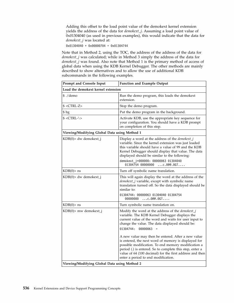
Adding this offset to the load point value of the demokext kernel extensionyields the address of the data for demokext_j. Assuming a load point value of0x01304040 (as used in previous examples), this would indicate that the data fordemokext_j was located at:
0x01304040 + 0x00000704 = 0x01304744
Note that in Method 2, using the TOC, the address of the address of the data fordemokext_j was calculated; while in Method 3 simply the address of the data fordemokext_j was found. Also note that Method 1 is the primary method of access ofglobal data when using the KDB Kernel Debugger. The other methods are mainlydescribed to show alternatives and to allow the use of additional KDBsubcommands in the following examples.
Prompt and Console Input Function and Example Output
Load the demokext kernel extension
$ ./demo Run the demo program, this loads the demokextextension.
$ <CTRL-Z> Stop the demo program.
$ bg Put the demo program in the background.
$ <CTRL-\> Activate KDB, use the appropriate key sequence foryour configuration. You should have a KDB prompton completion of this step.
Viewing/Modifying Global Data using Method 1
KDB(0)> dw demokext_j Display a word at the address of the demokext_jvariable. Since the kernel extension was just loadedthis variable should have a value of 99 and the KDBKernel Debugger should display that value. The datadisplayed should be similar to the following:
demokext_j+000000: 00000063 0130404001304754 00000000 ...c.0@@.0GT....
KDB(0)> ns Turn off symbolic name translation.
KDB(0)> dw demokext_j This will again display the word at the address of thedemokext_j variable, except with symbolic nametranslation turned off. So the data displayed should besimilar to:
01304744: 00000063 01304040 0130475400000000 ...c.0@@.0GT....
KDB(0)> ns Turn symbolic name translation on.
KDB(0)> mw demokext_j Modify the word at the address of the demokext_jvariable. The KDB Kernel Debugger displays thecurrent value of the word and waits for user input tochange the value. The data displayed should be:
01304744: 00000063 =
A new value may then be entered. After a new valueis entered, the next word of memory is displayed forpossible modification. To end memory modification aperiod (.) is entered. So to complete this step, enter avalue of 64 (100 decimal) for the first address and thenenter a period to end modification.
Viewing/Modifying Global Data using Method 2
536 Kernel Extensions and Device Support Programming Concepts

Prompt and Console Input Function and Example Output
KDB(0)> b demokext+e0 Set a break at line 67 of the demokext routine (see theexamples in the previous section). Breaking at thislocation will insure that the KDB Kernel Debugger isinvoked while within the demokext routines. Then wecan get the value of General Purpose Register 2, todetermine the address of the TOC.
KDB(0)> g Exit the KDB Kernel Debugger. This exits thedebugger and we can then bring the demo program tothe foreground and choose a selection to cause thedemokext routine to be called for configuration. Sincea break has been set this will cause the KDB KernelDebugger to be invoked.
$ fg Bring the demo program to the foreground.
./demo 1 Enter a value of 1 to select the option to increment thecounters within the demokext kernel extension. Thiscauses a break at line 67 of demokext.
KDB(0)> dr Display the general purpose registers. The datadisplayed should be similar to the following:
r0 : 0130411C r1 : 2FF3B210r2 : 01304754 r3 : 01304744r4 : 0047B180 r5 : 0047B230r6 : 000005FB r7 : 000DD300r8 : 000005FB r9 : 000DD300r10 : 00000000 r11 : 00000000r12 : 013042F4 r13 : DEADBEEFr14 : 00000001 r15 : 2FF22D80r16 : 2FF22D88 r17 : 00000000r18 : DEADBEEF r19 : DEADBEEFr20 : DEADBEEF r21 : DEADBEEFr22 : DEADBEEF r23 : DEADBEEFr24 : 2FF3B6E0 r25 : 2FF3B400r26 : 10000574 r27 : 22222484r28 : E3001E30 r29 : E6001800r30 : 01304744 r31 : 01304648
Using the map, the offset to the TOC entry fordemokext_j from the start of the TOC was 0x00000008(see the above text concerning Method 2). Adding thisoffset to the value displayed for r2 indicates that theTOC entry of interest is at: 0x0130475C. Note, the KDBKernel Debugger may be used to perform theaddition. In this case the subcommand to use wouldbe hcal @r2+8.
KDB(0)> dw 0130475C Display the TOC entry for demokext_j. This entry willcontain the address of the data for demokext_j. Thedata displayed should be similar to:
TOC+000008: 01304744 000BCB34 00242E94001E0518 .0GD...4.$......
The value for the first word displayed is the addressof the data for the demokext_j variable.
Chapter 17. Debugging Tools 537

Prompt and Console Input Function and Example Output
KDB(0)> dw 01304744 Display the data for demokext_j. The data displayedshould indicate that the value for demokext_j is still0x0000064, which we set it to earlier. This is becausethe breakpoint set was in the demokext routine priorto demokext_j being incremented. The data displayedshould be similar to:
demokext_j+000000: 00000064 0130404001304754 00000000 ...d.0@@.0GT....
KDB(0)> ca Clear all breakpoints.
KDB(0)> g Exit the kernel debugger. Be careful here, when weexit, the demo program will still be in the foregroundand there will be a prompt for the next option. Alsonote that the kernel extension is going to run andincrement demokext_j; so next time it should have avalue of 0x00000065.
Enter choice: <CTRL-Z> Enter <CTRL-Z> to stop the demo program.
$ bg Place the demo program in the background.
Viewing/Modifying Global Data using Method 3
$ <CTRL-\> Activate KDB, use the appropriate key sequence foryour configuration. You should have a KDB prompton completion of this step.
KDB(0)> dw demokext+704 Display the data for the demokext_j variable. The 704value is calculated from the map (refer to the abovetext for Method 3). This offset is then added to theload point of the demokext routine. Though there arenumerous ways to find this address, in this case thesimpliest is to just use the symbolic name; to reviewother options refer back to the Setting Breakpointssection. As mentioned, earlier the value for demokext_jshould now be 0x00000065. The data displayed shouldbe similar to:
demokext_j+000000: 00000065 0130404001304754 00000000 ...e.0@@.0GT....
KDB(0)> g Exit the KDB Kernel Debugger.
$ fg Bring the demo program to the foreground.
./demo 0 Enter an option of 0 to unload the demokext kernelextension and exit.
Stack TraceThe stack trace gives the stack history. This provides the sequence of procedurecalls leading to the current IAR. The Saved LR is the address of the instructioncalling this procedure. You can use the map file to locate the name of theprocedure. Note that the first stack frame shown is almost always useless, sincedata either has not been saved yet, or is from a previous call. The last functionpreceding the Saved LR is the function that called the procedure.
The following is a concise view of the stack:
Low | |Stack grows atAddresses | |this end.
|——————————|Callee's stack -> 0 | Back chain |pointer 4 | Saved CR |
538 Kernel Extensions and Device Support Programming Concepts
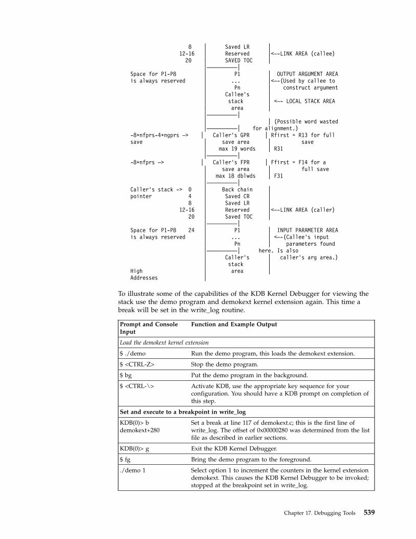
8 | Saved LR |12-16 | Reserved |<—-LINK AREA (callee)
20 | SAVED TOC ||——————————|
Space for P1-P8 | P1 | OUTPUT ARGUMENT AREAis always reserved | ... |<—-(Used by callee to
| Pn | construct argument| Callee's || stack | <—- LOCAL STACK AREA| area ||——————————|| | (Possible word wasted|——————————| for alignment.)
-8*nfprs-4*ngprs —> | Caller's GPR | Rfirst = R13 for fullsave | save area | save
| max 19 words | R31|——————————|
-8*nfprs —> | Caller's FPR | Ffirst = F14 for a| save area | full save| max 18 dblwds | F31|——————————|
Caller's stack -> 0 | Back chain |pointer 4 | Saved CR |
8 | Saved LR |12-16 | Reserved |<—-LINK AREA (caller)
20 | Saved TOC ||——————————|
Space for P1-P8 24 | P1 | INPUT PARAMETER AREAis always reserved | ... | <—-(Callee's input
| Pn | parameters found|——————————| here. Is also| Caller's | caller's arg area.)| stack |
High | area |Addresses |
To illustrate some of the capabilities of the KDB Kernel Debugger for viewing thestack use the demo program and demokext kernel extension again. This time abreak will be set in the write_log routine.
Prompt and ConsoleInput
Function and Example Output
Load the demokext kernel extension
$ ./demo Run the demo program, this loads the demokext extension.
$ <CTRL-Z> Stop the demo program.
$ bg Put the demo program in the background.
$ <CTRL-\> Activate KDB, use the appropriate key sequence for yourconfiguration. You should have a KDB prompt on completion ofthis step.
Set and execute to a breakpoint in write_log
KDB(0)> bdemokext+280
Set a break at line 117 of demokext.c; this is the first line ofwrite_log. The offset of 0x00000280 was determined from the listfile as described in earlier sections.
KDB(0)> g Exit the KDB Kernel Debugger.
$ fg Bring the demo program to the foreground.
./demo 1 Select option 1 to increment the counters in the kernel extensiondemokext. This causes the KDB Kernel Debugger to be invoked;stopped at the breakpoint set in write_log.
Chapter 17. Debugging Tools 539

Prompt and ConsoleInput
Function and Example Output
View the stack
KDB(0)> stack This displays the stack for the current process, which was the thedemo program calling the demokext kernel extension (since therewas a break set). The stack trace back displays the routines calledand even traces back through system calls. The displayed datashould be similar to:
thread+001800 STACK:[013042C0]write_log+00001C (10002040,
2FF3B258, 2FF3B2BC)[013040B0]demokext+000070 (00000001,
2FF3B338)[001E3BF4]config_kmod+0000F0 (??, ??, ??)[001E3FA8]sysconfig+000140 (??, ??, ??)[000039D8].sys_call+000000 ()[10000570]main+000280 (??, ??)[10000188]__start+000088 ()
KDB(0)> s 4 This subcommand steps 4 instructions. This should get into astrlen call. If it doesn’t, continue stepping until strlen is entered.
KDB(0)> stack Reexamine the stack. It should now include the strlen call andshould be similar to:
thread+001800 STACK:[01304500]strlen+000000 ()[013042CC]write_log+000028 (10002040,
2FF3B258, 2FF3B2BC)[013040B0]demokext+000070 (00000001,
2FF3B338)[001E3BF4]config_kmod+0000F0 (??, ??, ??)[001E3FA8]sysconfig+000140 (??, ??, ??)[000039D8].sys_call+000000 ()[10000570]main+000280 (??, ??)[10000188]__start+000088 ()
KDB(0)> setdisplay_stack_frames
This subcommand toggles a KDB Kernel Debugger option todisplay the top (lower addresses) 64 bytes for each stack frame.
540 Kernel Extensions and Device Support Programming Concepts

Prompt and ConsoleInput
Function and Example Output
KDB(0)> stack Redisplay the stack with the display_stack_frames option turnedon. The output should be similar to:
thread+001800 STACK:[01304510]strlen+000000 ()===================================================2FF3B1C0: 2FF3 B210 2FF3 B380 0130 4364 0000 0000
/.../....0Cd....2FF3B1D0: 2FF3 B230 0130 4754 0023 AD5C 2222 2082
/..0.0GT.#.\"" .2FF3B1E0: 0012 0000 2FF3 B400 0000 0480 0000 510C
..../.........Q.2FF3B1F0: 2FF3 B260 4A22 2860 001D CEC8 0000 153C
/..′J"(′.......|.... ... ...2FF3B3E0: 2000 A1D8 0000 0000 0000 0000 0000 0000
...............2FF3B3F0: 0000 0000 0024 FA90 0000 0000 0000 0000
.....$..........====================================================[000039D8].sys_call+000000 ()====================================================2FF21AA0: 2FF2 2D30 0000 0000 1000 0574 0000 0000
/.-0.......t....2FF21AB0: 0000 0000 2000 0B14 2000 08AC 2FF2 1AE0
.... ... .../...2FF21AC0: 0000 000E F014 992D 6F69 6365 3A20 0000
.......-oice: ..2FF21AD0: FFFF FFFF D012 D1C0 0000 0000 0000 0000
................====================================================[10000570]main+000280 (??, ??)====================================================2FF22D30: 0000 0000 0000 0000 1000 018C 0000 0000
................2FF22D40: 0000 0000 0000 0000 0000 0000 0000 0000
................2FF22D50: 0000 0000 0000 0000 0000 0000 0000 0000
................2FF22D60: 0000 0000 0000 0000 0000 0000 0000 0000
................====================================================[10000188]__start+000088 ()
The displayed data can be interpreted using the diagrampresented at the first of this section.
KDB(0)> setdisplay_stack_frames
Toggle the display_stack_frames option off.
KDB(0)> setdisplay_stacked_regs
This subcommand toggles a KDB Kernel Debugger option todisplay the registers saved in each stack frame.
Chapter 17. Debugging Tools 541
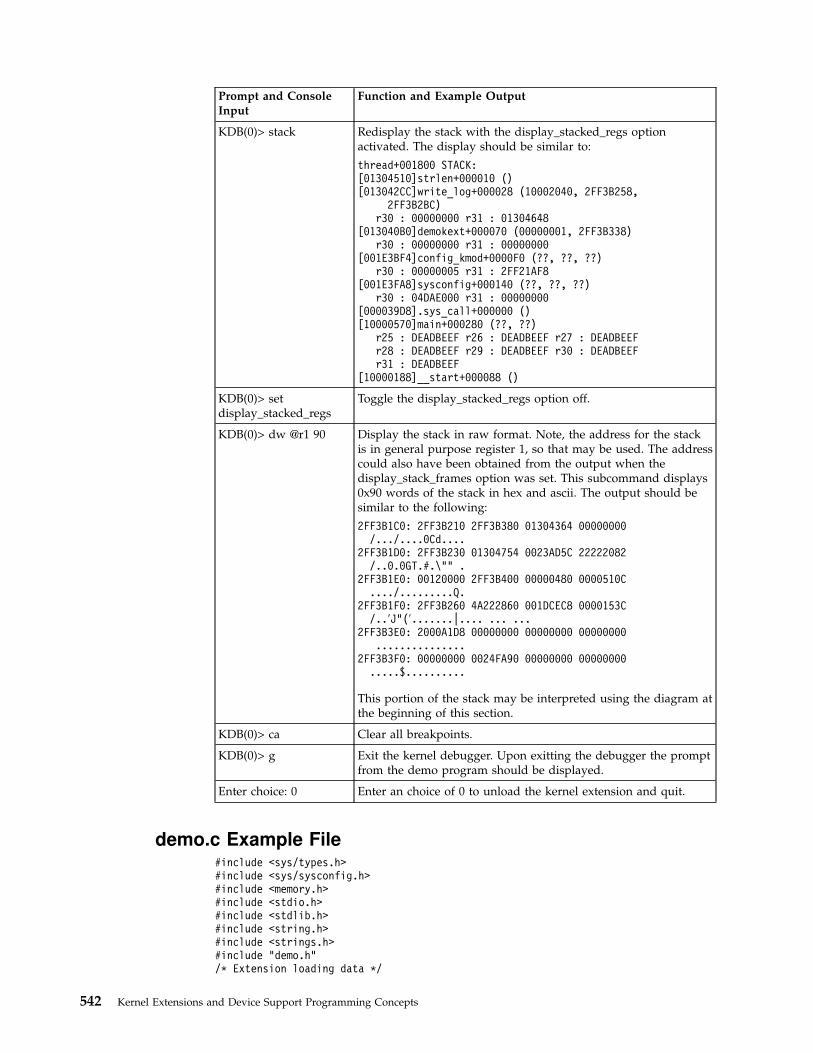
Prompt and ConsoleInput
Function and Example Output
KDB(0)> stack Redisplay the stack with the display_stacked_regs optionactivated. The display should be similar to:
thread+001800 STACK:[01304510]strlen+000010 ()[013042CC]write_log+000028 (10002040, 2FF3B258,
2FF3B2BC)r30 : 00000000 r31 : 01304648
[013040B0]demokext+000070 (00000001, 2FF3B338)r30 : 00000000 r31 : 00000000
[001E3BF4]config_kmod+0000F0 (??, ??, ??)r30 : 00000005 r31 : 2FF21AF8
[001E3FA8]sysconfig+000140 (??, ??, ??)r30 : 04DAE000 r31 : 00000000
[000039D8].sys_call+000000 ()[10000570]main+000280 (??, ??)
r25 : DEADBEEF r26 : DEADBEEF r27 : DEADBEEFr28 : DEADBEEF r29 : DEADBEEF r30 : DEADBEEFr31 : DEADBEEF
[10000188]__start+000088 ()
KDB(0)> setdisplay_stacked_regs
Toggle the display_stacked_regs option off.
KDB(0)> dw @r1 90 Display the stack in raw format. Note, the address for the stackis in general purpose register 1, so that may be used. The addresscould also have been obtained from the output when thedisplay_stack_frames option was set. This subcommand displays0x90 words of the stack in hex and ascii. The output should besimilar to the following:
2FF3B1C0: 2FF3B210 2FF3B380 01304364 00000000/.../....0Cd....
2FF3B1D0: 2FF3B230 01304754 0023AD5C 22222082/..0.0GT.#.\"" .
2FF3B1E0: 00120000 2FF3B400 00000480 0000510C..../.........Q.
2FF3B1F0: 2FF3B260 4A222860 001DCEC8 0000153C/..′J"(′.......|.... ... ...
2FF3B3E0: 2000A1D8 00000000 00000000 00000000...............
2FF3B3F0: 00000000 0024FA90 00000000 00000000.....$..........
This portion of the stack may be interpreted using the diagram atthe beginning of this section.
KDB(0)> ca Clear all breakpoints.
KDB(0)> g Exit the kernel debugger. Upon exitting the debugger the promptfrom the demo program should be displayed.
Enter choice: 0 Enter an choice of 0 to unload the kernel extension and quit.
demo.c Example File#include <sys/types.h>#include <sys/sysconfig.h>#include <memory.h>#include <stdio.h>#include <stdlib.h>#include <string.h>#include <strings.h>#include "demo.h"/* Extension loading data */
542 Kernel Extensions and Device Support Programming Concepts
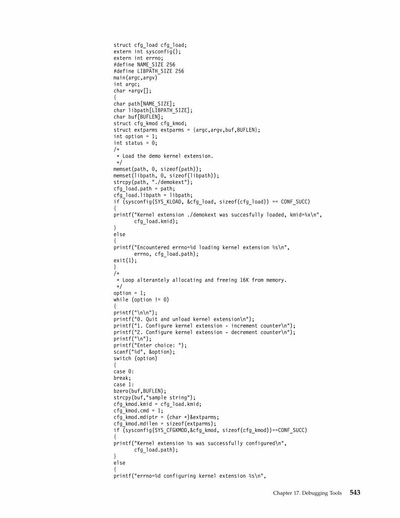
struct cfg_load cfg_load;extern int sysconfig();extern int errno;#define NAME_SIZE 256#define LIBPATH_SIZE 256main(argc,argv)int argc;char *argv[];{char path[NAME_SIZE];char libpath[LIBPATH_SIZE];char buf[BUFLEN];struct cfg_kmod cfg_kmod;struct extparms extparms = {argc,argv,buf,BUFLEN};int option = 1;int status = 0;/** Load the demo kernel extension.*/memset(path, 0, sizeof(path));memset(libpath, 0, sizeof(libpath));strcpy(path, "./demokext");cfg_load.path = path;cfg_load.libpath = libpath;if (sysconfig(SYS_KLOAD, &cfg_load, sizeof(cfg_load)) == CONF_SUCC){printf("Kernel extension ./demokext was succesfully loaded, kmid=%x\n",
cfg_load.kmid);}else{printf("Encountered errno=%d loading kernel extension %s\n",
errno, cfg_load.path);exit(1);}/** Loop alterantely allocating and freeing 16K from memory.*/option = 1;while (option != 0){printf("\n\n");printf("0. Quit and unload kernel extension\n");printf("1. Configure kernel extension - increment counter\n");printf("2. Configure kernel extension - decrement counter\n");printf("\n");printf("Enter choice: ");scanf("%d", &option);switch (option){case 0:break;case 1:bzero(buf,BUFLEN);strcpy(buf,"sample string");cfg_kmod.kmid = cfg_load.kmid;cfg_kmod.cmd = 1;cfg_kmod.mdiptr = (char *)&extparms;cfg_kmod.mdilen = sizeof(extparms);if (sysconfig(SYS_CFGKMOD,&cfg_kmod, sizeof(cfg_kmod))==CONF_SUCC){printf("Kernel extension %s was successfully configured\n",
cfg_load.path);}else{printf("errno=%d configuring kernel extension %s\n",
Chapter 17. Debugging Tools 543

errno, cfg_load.path);}break;case 2:bzero(buf,BUFLEN);strcpy(buf,"sample string");cfg_kmod.kmid = cfg_load.kmid;cfg_kmod.cmd = 2;cfg_kmod.mdiptr = (char *)&extparms;cfg_kmod.mdilen = sizeof(extparms);if (sysconfig(SYS_CFGKMOD,&cfg_kmod, sizeof(cfg_kmod))==CONF_SUCC){printf("Kernel extension %s was successfully configured\n",
cfg_load.path);}else{printf("errno=%d configuring kernel extension %s\n",
errno, cfg_load.path);}break;default:printf("\nUnknown option\n");break;}}/** Unload the demo kernel extension.*/
if (sysconfig(SYS_KULOAD, &cfg_load, sizeof(cfg_load)) == CONF_SUCC){printf("Kernel extension %s was successfully unloaded\n", cfg_load.path);}else{printf("errno=%d unloading kernel extension %s\n", errno, cfg_load.path);}}
demokext.c Example File#include <sys/types.h>#include <sys/malloc.h>#include <sys/uio.h>#include <sys/dump.h>#include <sys/errno.h>#include <sys/uprintf.h>#include <fcntl.h>#include "demo.h"/* Log routine prototypes */int open_log(char *path, struct file **fpp);int write_log(struct file *fpp, char *buf, int *bytes_written);int close_log(struct file *fpp);/* Unexported symbol */int demokext_i = 9;/* Exported symbol */int demokext_j = 99;/** Kernel extension entry point, called at config. time.** input:* cmd - unused (typically 1=config, 2=unconfig)* uiop - points to the uio structure.*/intdemokext(int cmd, struct uio *uiop){
544 Kernel Extensions and Device Support Programming Concepts

int rc;char *bufp;struct file *fpp;int fstat;char buf[100];int bytes_written;static int j = 0;/** Open the log file.*/strcpy(buf, "./demokext.log");fstat = open_log(buf, &fpp);if (fstat != 0) return(fstat);/** Put a message out to the log file.*/strcpy(buf, "demokext was called for configuration\n");fstat = write_log(fpp, buf, &bytes_written);if (fstat != 0) return(fstat);/** Increment or decrement j and demokext_j based on* the input value for cmd.*/{switch (cmd){case 1: /* Increment */sprintf(buf, "Before increment: j=%d demokext_j=%d\n",
j, demokext_j);write_log(fpp, buf, &bytes_written);demokext_j++;j++;sprintf(buf, "After increment: j=%d demokext_j=%d\n",
j, demokext_j);write_log(fpp, buf, &bytes_written);break;case 2: /* Decrement */sprintf(buf, "Before decrement: j=%d demokext_j=%d\n",
j, demokext_j);write_log(fpp, buf, &bytes_written);demokext_j—;j—;sprintf(buf, "After decrement: j=%d demokext_j=%d\n",
j, demokext_j);write_log(fpp, buf, &bytes_written);break;default: /* Unknown command value */sprintf(buf, "Received unknown command of %d\n", cmd);write_log(fpp, buf, &bytes_written);break;}}/** Close the log file.*/fstat = close_log(fpp);if (fstat !=0 ) return(fstat);return(0);}/**************************************************** Routines for logging debug information: ** open_log - Opens a log file ** write_log - Output a string to a log file ** close_log - Close a log file ****************************************************/int open_log (char *path, struct file **fpp){
Chapter 17. Debugging Tools 545
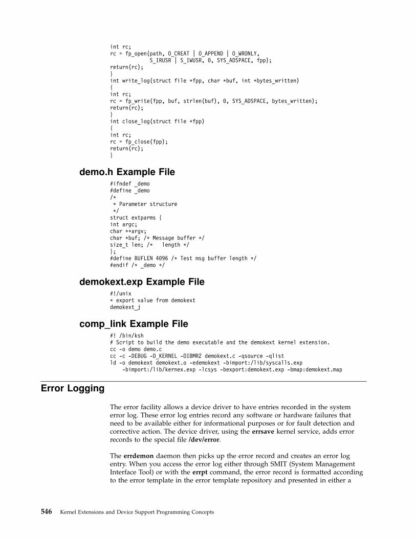
int rc;rc = fp_open(path, O_CREAT | O_APPEND | O_WRONLY,
S_IRUSR | S_IWUSR, 0, SYS_ADSPACE, fpp);return(rc);}int write_log(struct file *fpp, char *buf, int *bytes_written){int rc;rc = fp_write(fpp, buf, strlen(buf), 0, SYS_ADSPACE, bytes_written);return(rc);}int close_log(struct file *fpp){int rc;rc = fp_close(fpp);return(rc);}
demo.h Example File#ifndef _demo#define _demo/** Parameter structure*/struct extparms {int argc;char **argv;char *buf; /* Message buffer */size_t len; /* length */};#define BUFLEN 4096 /* Test msg buffer length */#endif /* _demo */
demokext.exp Example File#!/unix* export value from demokextdemokext_j
comp_link Example File#! /bin/ksh# Script to build the demo executable and the demokext kernel extension.cc -o demo demo.ccc -c -DEBUG -D_KERNEL -DIBMR2 demokext.c -qsource -qlistld -o demokext demokext.o -edemokext -bimport:/lib/syscalls.exp
-bimport:/lib/kernex.exp -lcsys -bexport:demokext.exp -bmap:demokext.map
Error Logging
The error facility allows a device driver to have entries recorded in the systemerror log. These error log entries record any software or hardware failures thatneed to be available either for informational purposes or for fault detection andcorrective action. The device driver, using the errsave kernel service, adds errorrecords to the special file /dev/error.
The errdemon daemon then picks up the error record and creates an error logentry. When you access the error log either through SMIT (System ManagementInterface Tool) or with the errpt command, the error record is formatted accordingto the error template in the error template repository and presented in either a
546 Kernel Extensions and Device Support Programming Concepts
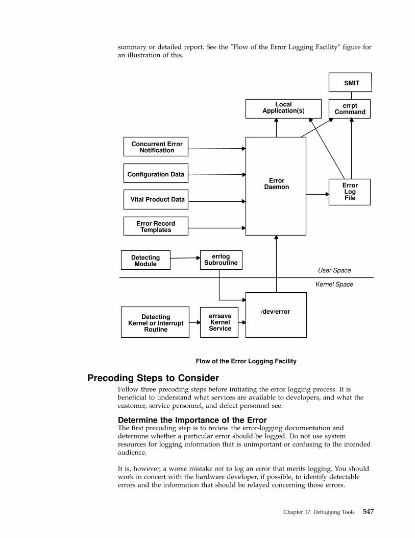
summary or detailed report. See the ″Flow of the Error Logging Facility″ figure foran illustration of this.
Precoding Steps to ConsiderFollow three precoding steps before initiating the error logging process. It isbeneficial to understand what services are available to developers, and what thecustomer, service personnel, and defect personnel see.
Determine the Importance of the ErrorThe first precoding step is to review the error-logging documentation anddetermine whether a particular error should be logged. Do not use systemresources for logging information that is unimportant or confusing to the intendedaudience.
It is, however, a worse mistake not to log an error that merits logging. You shouldwork in concert with the hardware developer, if possible, to identify detectableerrors and the information that should be relayed concerning those errors.
Concurrent ErrorNotification
Vital Product Data
errptCommand
SMIT
LocalApplication(s)
Configuration Data
Error RecordTemplates
DetectingModule
errlogSubroutine
DetectingKernel or Interrupt
Routine
errsaveKernelService
/dev/error
User Space
Kernel Space
ErrorLogFile
ErrorDaemon
Flow of the Error Logging Facility
Chapter 17. Debugging Tools 547

Determine the Text of the MessageThe next step is to determine the text of the message. Use the errmsg commandwith the -w flag to browse the system error messages file for a list of availablemessages. If you are developing a product for wide-spread general distributionand do not find a suitable system error message, you can submit a request to yoursupplier for a new message or follow the procedures that your organization uses torequest new error messages. If your product is an in-house application, you canuse the errmsg command to define a new message that meets your requirements.
Determine the Correct Level of ThresholdingFinally, determine the correct level of thresholding. Each error to be logged,regardless of whether it is a software or hardware error, can be limited bythresholding to avoid filling the error log with duplicate information.
Side effects of runaway error logging include overwriting existing error log entriesand unduly alarming the end user. The error log is not unlimited in size. When itssize limit is reached, the log wraps. If a particular error is repeated needlessly,existing information is overwritten, possibly causing inaccurate diagnosticanalyses. The end user or service person can perceive a situation as more seriousor pervasive than it is if they see hundreds of identical or nearly identical errorentries.
You are responsible for implementing the proper level of thresholding in the devicedriver code.
The error log currently equals 1MB. As shipped, it cleans up any entries older than30 days. In order to ensure that your error log entries are actually informative,noticed, and remain intact, test your driver thoroughly.
Coding Steps
To begin error logging,
1. Select the error text.
2. Construct error record templates.
3. Add error logging calls into the device driver code.
Selecting the Error TextThe first task is to select the error text. After browsing the contents of the systemmessage file, three possible paths exist for selecting the error text. Either all of thedesired messages for the new errors exist in the message file, none of the messagesexist, or a combination of errors exists.
v If the messages required already exist in the system message file, make a note ofthe four-digit hexadecimal identification number, as well as the message-setidentification letter. For instance, a desired error description can be:
SET EE859 "The wagon wheel is broken."
v If none of the system error messages meet your requirements, and if you areresponsible for developing a product for wide-spread general distribution, youcan either contact your supplier to allocate new messages or follow theprocedures that your organization uses to request new messages. If you arecreating an in-house product, use the errmsg command to write suitable errormessages and use the errinstall command to install them. Refer to ″SoftwareProduct Packaging″ in AIX Version 4.3 General Programming Concepts: Writing andDebugging Programs for more information. Take care not to overwrite other errormessages.
548 Kernel Extensions and Device Support Programming Concepts

v It is also possible to use a combination of existing messages and new messageswithin the same error record template definition.
Constructing Error Record Templates
The second step is to construct your error record templates. An error record templatedefines the text that appears in the error report. Each error record template has thefollowing general form:
Error Record Template+LABEL:
Comment =Class =Log =Report =Alert =Err_Type =Err_Desc =Probable_Causes =User_Causes =User_Actions =Inst_Causes =Inst_Actions =Fail_Causes =Fail_Actions =Detail_Data = <data_len>, <data_id>, <data_encoding>
Each field in this stanza has well-defined criteria for input values. See theerrupdate command for more information. The fields are:
Label Requires a unique label for each entry to be added. The label mustfollow C language rules for identifiers and must not exceed 16characters in length.
Comment Indicates this is a comment field. You must enclose the comment indouble quotation marks; and it cannot exceed 40 characters.
Class Requires class values of H (hardware), S (software), or U(Undetermined).
Log Requires values True or False. If failure occurs, the errors are loggedonly if this field value is set to True. When this value is False the Reportand Alert fields are ignored.
Report The values for this field are True or False. If the logged error is to bedisplayed using error report, the value of this field must be True.
Alert Set this field to True for errors that are alertable. For errors that are notalertable, set this field to False.
Chapter 17. Debugging Tools 549
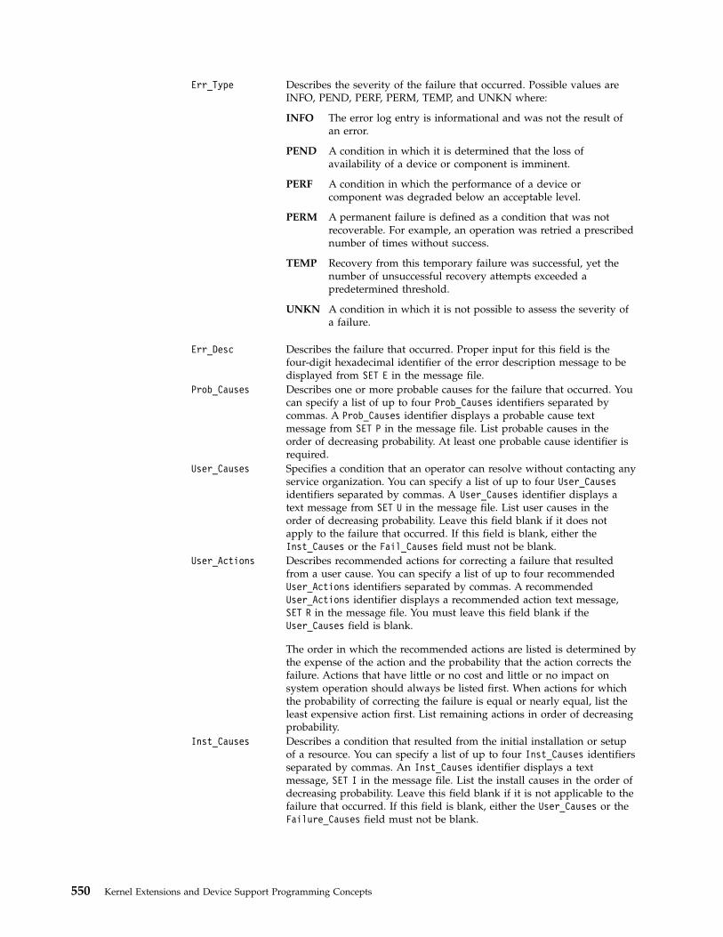
Err_Type Describes the severity of the failure that occurred. Possible values areINFO, PEND, PERF, PERM, TEMP, and UNKN where:
INFO The error log entry is informational and was not the result ofan error.
PEND A condition in which it is determined that the loss ofavailability of a device or component is imminent.
PERF A condition in which the performance of a device orcomponent was degraded below an acceptable level.
PERM A permanent failure is defined as a condition that was notrecoverable. For example, an operation was retried a prescribednumber of times without success.
TEMP Recovery from this temporary failure was successful, yet thenumber of unsuccessful recovery attempts exceeded apredetermined threshold.
UNKN A condition in which it is not possible to assess the severity ofa failure.
Err_Desc Describes the failure that occurred. Proper input for this field is thefour-digit hexadecimal identifier of the error description message to bedisplayed from SET E in the message file.
Prob_Causes Describes one or more probable causes for the failure that occurred. Youcan specify a list of up to four Prob_Causes identifiers separated bycommas. A Prob_Causes identifier displays a probable cause textmessage from SET P in the message file. List probable causes in theorder of decreasing probability. At least one probable cause identifier isrequired.
User_Causes Specifies a condition that an operator can resolve without contacting anyservice organization. You can specify a list of up to four User_Causesidentifiers separated by commas. A User_Causes identifier displays atext message from SET U in the message file. List user causes in theorder of decreasing probability. Leave this field blank if it does notapply to the failure that occurred. If this field is blank, either theInst_Causes or the Fail_Causes field must not be blank.
User_Actions Describes recommended actions for correcting a failure that resultedfrom a user cause. You can specify a list of up to four recommendedUser_Actions identifiers separated by commas. A recommendedUser_Actions identifier displays a recommended action text message,SET R in the message file. You must leave this field blank if theUser_Causes field is blank.
The order in which the recommended actions are listed is determined bythe expense of the action and the probability that the action corrects thefailure. Actions that have little or no cost and little or no impact onsystem operation should always be listed first. When actions for whichthe probability of correcting the failure is equal or nearly equal, list theleast expensive action first. List remaining actions in order of decreasingprobability.
Inst_Causes Describes a condition that resulted from the initial installation or setupof a resource. You can specify a list of up to four Inst_Causes identifiersseparated by commas. An Inst_Causes identifier displays a textmessage, SET I in the message file. List the install causes in the order ofdecreasing probability. Leave this field blank if it is not applicable to thefailure that occurred. If this field is blank, either the User_Causes or theFailure_Causes field must not be blank.
550 Kernel Extensions and Device Support Programming Concepts

Inst_Actions Describes recommended actions for correcting a failure that resultedfrom an install cause. You can specify a list of up to four recommendedInst_actions identifiers separated by commas. A recommendedInst_actions identifier identifies a recommended action text message,SET R in the message file. Leave this field blank if the Inst_Causes fieldis blank. The order in which the recommended actions are listed isdetermined by the expense of the action and the probability that theaction corrects the failure. See the User_Actions field for the list criteria.
Fail_Causes Describes a condition that resulted from the failure of a resource. Youcan specify a list of up to four Fail_Causes identifiers separated bycommas. A Fail_Causes identifier displays a failure cause text message,SET F in the message file. List the failure causes in the order ofdecreasing probability. Leave this field blank if it is not applicable to thefailure that occurred. If you leave this field blank, either the User_Causesor the Inst_Causes field must not be blank.
Fail_Actions Describes recommended actions for correcting a failure that resultedfrom a failure cause. You can specify a list of up to four recommendedaction identifiers separated by commas. The Fail_Actions identifiersmust correspond to recommended action messages found in SET R of themessage file. Leave this field blank if the Fail_Causes field is blank.Refer to the description of the User_Actions field for criteria in listingthese recommended actions.
Detail_Data Describes the detailed data that is logged with the error when the failureoccurs. The Detail_data field includes the name of the detectingmodule, sense data, or return codes. Leave this field blank if no detaileddata is logged with the error.
You can repeat the Detail_Data field. The amount of data logged withan error must not exceed the maximum error record length defined inthe sys/err_rec.h header file. Save failure data that cannot be containedin an error log entry elsewhere, for example in a file. The detailed datain the error log entry contains information that can be used to correlatethe failure data to the error log entry. Three values are required for eachdetail data entry:
data_lenIndicates the number of bytes of data to be associated with thedata_id value. The data_len value is interpreted as a decimalvalue.
data_id Identifies a text message to be printed in the error report infront of the detailed data. These identifiers refer to messages inSET D of the message file.
data_encodingDescribes how the detailed data is to be printed in the errorreport. Valid values for this field are:
ALPHAThe detailed data is a printable ASCII character string.
DEC The detailed data is the binary representation of aninteger value, the decimal equivalent is to be printed.
HEX The detailed data is to be printed in hexadecimal.
Sample Error Record TemplateAn example of an error record template is:
+ MISC_ERR:Comment = "Interrupt: I/O bus timeout or channel check"Class = H
Chapter 17. Debugging Tools 551

Log = TRUEReport = TRUEAlert = FALSEErr_Type = UNKNErr_Desc = E856Prob_Causes = 3300, 6300User_Causes =User_Actions =Inst_Causes =Inst_Actions =Fail_Causes = 3300, 6300Fail_Actions = 0000Detail_Data = 4, 8119, HEX *IOCC bus numberDetail_Data = 4, 811A, HEX *Bus Status RegisterDetail_Data = 4, 811B, HEX *Misc. Interrupt Register
Construct the error templates for all new errors to be added in a file suitable forentry with the errupdate command. Run the errupdate command with the -h flagand the input file. The new errors are now part of the error record templaterepository. A new header file is also created (file.h) in the same directory in whichthe errupdate command was run. This header file must be included in the devicedriver code at compile time. Note that the errupdate command has a built-insyntax checker for the new stanza that can be called with the -c flag.
Adding Error Logging Calls into the Code
The third step in coding error logging is to put the error logging calls into thedevice driver code. The errsave kernel service allows the kernel and kernelextensions to write to the error log. Typically, you define a routine in the devicedriver that can be called by other device driver routines when a loggable error isencountered. This function takes the data passed to it, puts it into the properstructure and calls the errsave kernel service. The syntax for the errsave kernelservice is:
#include <sys/errids.h>void errsave(buf, cnt)char *buf;unsigned int cnt;
where,
buf Specifies a pointer to a buffer that contains an error record as described in thesys/errids.h header file.
cnt Specifies a number of bytes in the error record contained in the buffer pointed to bythe buf parameter.
The following sample code is an example of a device driver error logging routine.This routine takes data passed to it from some part of the main body of the devicedriver. This code simply fills in the structure with the pertinent information, thenpasses it on using the errsave kernel service.
voiderrsv_ex (int err_id, unsigned int port_num,
int line, char *file, uint data1, uint data2){
dderr log;char errbuf[255];ddex_dds *p_dds;p_dds = dds_dir[port_num];log.err.error_id = err_id;if (port_num = BAD_STATE) {
sprintf(log.err.resource_name, "%s :%d",
552 Kernel Extensions and Device Support Programming Concepts

p_dds->dds_vpd.adpt_name, data1);data1 = 0;
}else
sprintf(log.err.resource_name,"%s",p_dds->dds_vpd.devname);sprintf(errbuf, "line: %d file: %s", line, file);strncpy(log.file, errbuf, (size_t)sizeof(log.file));log.data1 = data1;log.data2 = data2;errsave(&log, (uint)sizeof(dderr)); /* run actual logging */
} /* end errlog_ex */
The data to be passed to the errsave kernel service is defined in the dderr structurewhich is defined in a local header file, dderr.h. The definition for dderr is:
typedef struct dderr {struct err_rec0 err;int data1; /* use data1 and data2 to show detail */int data2; /* data in the errlog report. Define */
/* these fields in the errlog template *//* These fields may not be used in all *//* cases. */
} dderr;
The first field of the dderr.h header file is comprised of the err_rec0 structure,which is defined in the sys/err_rec.h header file. This structure contains the ID (orlabel) and a field for the resource name. The two data fields hold the detail datafor the error log report. As an alternative, you could simply list the fields withinthe function.
You can also log a message into the error log from the command line. To do this,use the errlogger command.
After you add the templates using the errupdate command, compile the devicedriver code along with the new header file. Simulate the error and verify that itwas written to the error log correctly. Some details to check for include:
v Is the error demon running? This can be verified by running the ps -efcommand and checking for /usr/lib/errdemon as part of the output.
v Is the error part of the error template repository? Verify this by running theerrpt -at command.
v Was the new header file, which was created by the errupdate command andwhich contains the error label and unique error identification number, includedin the device driver code when it was compiled?
Writing to the /dev/error Special FileThe error logging process begins when a loggable error is encountered and thedevice driver error logging subroutine sends the error information to the errsavekernel service. The error entry is written to the /dev/error special file. Once theinformation arrives at this file, it is time-stamped by the errdemon daemon andput in a buffer. The errdemon daemon constantly checks the /dev/error special filefor new entries, and when new data is written, the daemon collects otherinformation pertaining to the resource reporting the error. The errdemon daemonthen creates an entry in the /var/adm/ras/errlog error logging file.
Chapter 17. Debugging Tools 553

Debug and Performance Tracing
The AIX trace facility is useful for observing a running device driver and system.The trace facility captures a sequential flow of time-stamped system events,providing a fine level of detail on system activity. Events are shown in timesequence and in the context of other events. The trace facility is useful inexpanding the trace event information to understand who, when, how, and evenwhy the event happened.
IntroductionThe operating system is shipped with permanent trace event points. These eventsprovide general visibility to system execution. You can extend the visibility intoapplications by inserting additional events and providing formatting rules.
Care was taken in the design and implementation of this facility to make thecollection of trace data efficient, so that system performance and flow would beminimally altered by activating trace. Because of this, the facility is extremelyuseful as a performance analysis tool and as a problem determination tool.
The trace facility is more flexible than traditional system monitor services thataccess and present statistics maintained by the system. With traditional monitorservices, data reduction (conversion of system events to statistics) is largelycoupled to the system instrumentation. For example, the system can maintain theminimum, maximum, and average elapsed time observed for runs of a task andpermit this information to be extracted.
The trace facility does not strongly couple data reduction to instrumentation, butprovides a stream of system events. It is not required to presuppose what statisticsare needed. The statistics or data reduction are to a large degree separated fromthe instrumentation.
You can choose to develop the minimum, maximum, and average time for task Afrom the flow of events. But it is also possible to extract the average time for taskA when called by process B, extract the average time for task A when conditionsXYZ are met, develop a standard deviation for task A, or even decide that someother task, recognized by a stream of events, is more meaningful to summarize.This flexibility is invaluable for diagnosing performance or functional problems.
The trace facility generates large volumes of data. This data cannot be captured forextended periods of time without overflowing the storage device. This allows twopractical ways that the trace facility can be used natively.
First, the trace facility can be triggered in multiple ways to capture smallincrements of system activity. It is practical to capture seconds to minutes ofsystem activity in this way for post-processing. This is sufficient time tocharacterize major application transactions or interesting sections of a long task.
Second, the trace facility can be configured to direct the event stream to standardoutput. This allows a realtime process to connect to the event stream and providedata reduction in real-time, thereby creating a long term monitoring capability. Alogical extension for specialized instrumentation is to direct the data stream to anauxiliary device that can either store massive amounts of data or provide dynamicdata reduction.
You can start the system trace from:
554 Kernel Extensions and Device Support Programming Concepts

v The command line
v SMIT
v Software
As shown in the ″Starting and Stopping Trace″ figure, the trace facility causespredefined events to be written to a trace log. The tracing action is then stopped.Tracing from a command line is discussed in “Controlling trace” on page 559.Tracing from a software application is discussed and an example is presented in“Examples of Coding Events and Formatting Events” on page 576.
After a trace is started and stopped, you must format it before viewing it. This isillustrated in the ″Trace Formatting″ figure. To format the trace events that youhave defined, you must provide a stanza that describes how the trace formatter isto interpret the data that has been collected. This is described in “Syntax forStanzas in the trace Format File” on page 568.
Invoke trace from: – command line – SMIT – software
Defined traceevents are writtento the trace log.
trace
Command
Trace
Log
Stop
Trace
Starting and Stopping Trace
Chapter 17. Debugging Tools 555

The trcrpt command provides a general purpose report facility. The report facilityprovides little data reduction, but converts the raw binary event stream to areadable ASCII listing of the event stream. Data can be visually extracted by areader, or tools can be developed to further reduce the data.
For an event to be traced, you must write an event hook (sometimes called a tracehook) into the code that you want to trace. Tracing can be done on either thesystem channel (channel 0) or on a generic channel (channels 1-7). All preshippedtrace points are output to the system channel.
Usually, when you want to show interaction with other system routines, use thesystem channel. The generic channels are provided so that you can control howmuch data is written to the trace log. Only your data is written to one of thegeneric channels.
For more information on trace hooks, see “Macros for Recording trace Events” onpage 565.
Using the trace FacilityThe following sections describe the use of the trace facility.
Configuring and Starting trace Data Collection
The trace command configures the trace facility and starts data collection. Thesyntax of this command is:
trace [ -a | -f | -l ] [ -c ] [ -d ] [ -h ] [ -j Event [ ,Event ] ][ -k Event [ ,Event ] ] [ -m Message ] [ -n ] [ -o OutName ] [ -o- ] [ -s ][ -L Size ] [ -T Size ] [-1234567]
Invoke formatterfrom: – command line – SMIT
Trcrpt filters thetrace log accordingto entries in yourformat file.
trcrpt
Command
Trace
Log
Formatted
Output File
Trace Formatting
556 Kernel Extensions and Device Support Programming Concepts

The various options of the trace command are:
-f or -l Control the capture of trace data in system memory. If youspecify neither the -f nor -l option, the trace facility createstwo buffer areas in system memory to capture the tracedata. These buffers are alternately written to the log file (orstandard output if specified) as they become full. The -f or -lflag provides you with the ability to prevent data frombeing written to the file during data collection. The optionsare to collect data only until the memory buffer becomes full(-f for first), or to use the memory buffer as a circular bufferthat captures only the last set of events that occurred beforetrace was terminated (-l). The -f and -l options are mutuallyexclusive. With either the -f or -l option, data is nottransferred from the memory collection buffers to file untiltrace is terminated.
-a Run the trace collection asynchronously (as a backgroundtask), returning a normal command line prompt. Withoutthis option, the trace command runs in a subcommandmode (similar to the crash command) and returns a >prompt. You can issue subcommands and regular shellcommands from the trace subcommand mode by precedingthe shell commands with an ! (exclamation point).
-c Saves the previous trace log file adding .old to its name.Generates an error if a previous trace log file does not exists.When using the -o Name flag, the user-defined trace log fileis renamed.
-d Delay data collection. The trace facility is only configured.Data collection is delayed until one of the collection triggerevents occurs. Various methods for triggering data collectionon and off are provided. These include the following:
v trace subcommands
v trace commands
v ioctls to /dev/systrctl
-j Event or -k Event Specifies a set of events to include (-j) or exclude (-k) fromthe collection process. The Event list items can be separatedby commas, or enclosed in double quotation marks andseparated by commas or blanks.
-s Terminate trace data collection if the trace log file reaches itsmaximum specified size. The default without this option isto wrap and overwrite the data in the log file on a FIFObasis.
-h Do not write a date/sysname/message header to the tracelog file.
-m Message Specify a text string (message) to be included in the tracelog header record. The message is included in reportsgenerated by the trcrpt command.
-n Adds some information to the trace log header: lockinformation, hardware information, and, for each loaderentry, the symbol name, address, and type.
-o Outfile Specify a file to use as the log file. If you do not use the -ooption, the default log file is /usr/adm/ras/trcfile. To directthe trace data to standard output, code the -o option as -o -.(When -o- is specified the -c flag is ignored.) Use thistechnique only to pipe the data stream to another processsince the trace data contains raw binary events that are notdisplayable.
Chapter 17. Debugging Tools 557
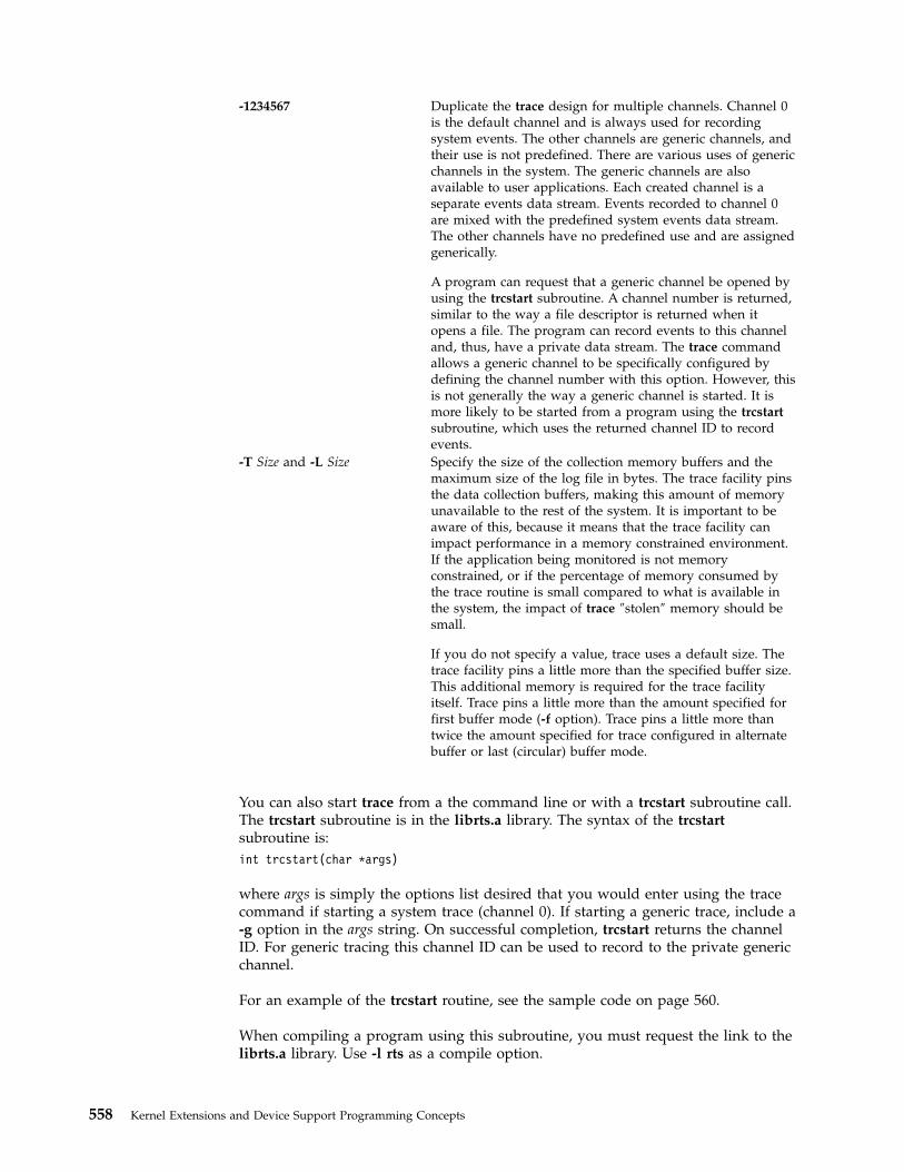
-1234567 Duplicate the trace design for multiple channels. Channel 0is the default channel and is always used for recordingsystem events. The other channels are generic channels, andtheir use is not predefined. There are various uses of genericchannels in the system. The generic channels are alsoavailable to user applications. Each created channel is aseparate events data stream. Events recorded to channel 0are mixed with the predefined system events data stream.The other channels have no predefined use and are assignedgenerically.
A program can request that a generic channel be opened byusing the trcstart subroutine. A channel number is returned,similar to the way a file descriptor is returned when itopens a file. The program can record events to this channeland, thus, have a private data stream. The trace commandallows a generic channel to be specifically configured bydefining the channel number with this option. However, thisis not generally the way a generic channel is started. It ismore likely to be started from a program using the trcstartsubroutine, which uses the returned channel ID to recordevents.
-T Size and -L Size Specify the size of the collection memory buffers and themaximum size of the log file in bytes. The trace facility pinsthe data collection buffers, making this amount of memoryunavailable to the rest of the system. It is important to beaware of this, because it means that the trace facility canimpact performance in a memory constrained environment.If the application being monitored is not memoryconstrained, or if the percentage of memory consumed bythe trace routine is small compared to what is available inthe system, the impact of trace ″stolen″ memory should besmall.
If you do not specify a value, trace uses a default size. Thetrace facility pins a little more than the specified buffer size.This additional memory is required for the trace facilityitself. Trace pins a little more than the amount specified forfirst buffer mode (-f option). Trace pins a little more thantwice the amount specified for trace configured in alternatebuffer or last (circular) buffer mode.
You can also start trace from a the command line or with a trcstart subroutine call.The trcstart subroutine is in the librts.a library. The syntax of the trcstartsubroutine is:
int trcstart(char *args)
where args is simply the options list desired that you would enter using the tracecommand if starting a system trace (channel 0). If starting a generic trace, include a-g option in the args string. On successful completion, trcstart returns the channelID. For generic tracing this channel ID can be used to record to the private genericchannel.
For an example of the trcstart routine, see the sample code on page 560.
When compiling a program using this subroutine, you must request the link to thelibrts.a library. Use -l rts as a compile option.
558 Kernel Extensions and Device Support Programming Concepts
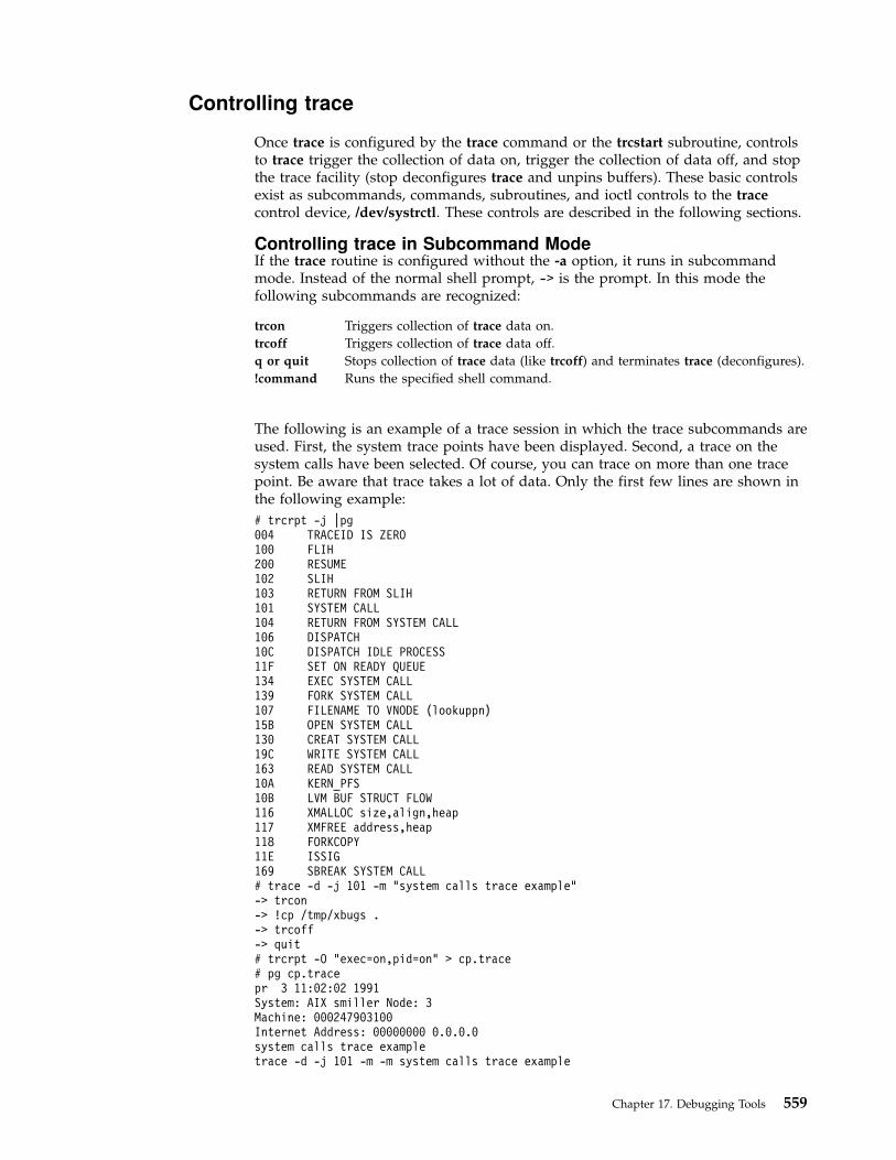
Controlling trace
Once trace is configured by the trace command or the trcstart subroutine, controlsto trace trigger the collection of data on, trigger the collection of data off, and stopthe trace facility (stop deconfigures trace and unpins buffers). These basic controlsexist as subcommands, commands, subroutines, and ioctl controls to the tracecontrol device, /dev/systrctl. These controls are described in the following sections.
Controlling trace in Subcommand ModeIf the trace routine is configured without the -a option, it runs in subcommandmode. Instead of the normal shell prompt, -> is the prompt. In this mode thefollowing subcommands are recognized:
trcon Triggers collection of trace data on.
trcoff Triggers collection of trace data off.
q or quit Stops collection of trace data (like trcoff) and terminates trace (deconfigures).
!command Runs the specified shell command.
The following is an example of a trace session in which the trace subcommands areused. First, the system trace points have been displayed. Second, a trace on thesystem calls have been selected. Of course, you can trace on more than one tracepoint. Be aware that trace takes a lot of data. Only the first few lines are shown inthe following example:
# trcrpt -j |pg004 TRACEID IS ZERO100 FLIH200 RESUME102 SLIH103 RETURN FROM SLIH101 SYSTEM CALL104 RETURN FROM SYSTEM CALL106 DISPATCH10C DISPATCH IDLE PROCESS11F SET ON READY QUEUE134 EXEC SYSTEM CALL139 FORK SYSTEM CALL107 FILENAME TO VNODE (lookuppn)15B OPEN SYSTEM CALL130 CREAT SYSTEM CALL19C WRITE SYSTEM CALL163 READ SYSTEM CALL10A KERN_PFS10B LVM BUF STRUCT FLOW116 XMALLOC size,align,heap117 XMFREE address,heap118 FORKCOPY11E ISSIG169 SBREAK SYSTEM CALL# trace -d -j 101 -m "system calls trace example"-> trcon-> !cp /tmp/xbugs .-> trcoff-> quit# trcrpt -O "exec=on,pid=on" > cp.trace# pg cp.tracepr 3 11:02:02 1991System: AIX smiller Node: 3Machine: 000247903100Internet Address: 00000000 0.0.0.0system calls trace exampletrace -d -j 101 -m -m system calls trace example
Chapter 17. Debugging Tools 559

ID PROCESS NAME PID I ELAPSED_SEC DELTA_MSEC APPL SYSCALL001 trace 13939 0.000000000 0.000000 TRACE ON chan 0101 trace 13939 0.000251392 0.251392 kwritev101 trace 13939 0.000940800 0.689408 sigprocmask101 trace 13939 0.001061888 0.121088 kreadv101 trace 13939 0.001501952 0.440064 kreadv101 trace 13939 0.001919488 0.417536 kioctl101 trace 13939 0.002395648 0.476160 kreadv101 trace 13939 0.002705664 0.310016 kioctl
Controlling the trace Facility by CommandsIf you configure the trace routine to run asynchronously (the -a option), you cancontrol the trace facility with the following commands:
trcon Triggers collection of trace data on.
trcoff Triggers collection of trace data off.
trcstop Stops collection of trace data (like trcoff) and terminates the trace routine.
Controlling the trace Facility by SubroutinesThe controls for the trace routine are available as subroutines from the librts.alibrary. The subroutines return zero on successful completion. The subroutines are:
trcon Triggers collection of trace data on.
trcoff Triggers collection of trace data off.
trcstop Stops collection of trace data (like trcoff) and terminates the trace routine.
Controlling the trace Facility with ioctls CallsThe subroutines for controlling trace open the trace control device (/dev/systrctl),issue the appropriate ioctl command, close the control device and return. Tocontrol tracing around sections of code, it can be more efficient for a program toissue the ioctl controls directly. This avoids the unnecessary, repetitive opening andclosing of the trace control device, at the expense of exposing some of theimplementation details of trace control. To use the ioctl call in a program, includesys/trcctl.h to define the ioctl commands. The syntax of the ioctl is as follows:
ioctl (fd, CMD, Channel)
where:
fd File descriptor returned from opening /dev/systrctl
CMD TRCON, TRCOFF, or TRCSTOP
Channel Trace channel (0 for system trace).
The following code sample shows how to start a trace from a program and onlytrace around a specified section of code:
#include <sys/trcctl.h>extern int trcstart(char *arg);char *ctl_dev ="/dev/systrctl";int ctl_fdmain(){
printf("configuring trace collection \n");if (trcstart("-ad")){perror("trcstart");
exit(1);}if((ctl_fd =open (ctl_dev))<0){
perror("open ctl_dev");exit(1);
560 Kernel Extensions and Device Support Programming Concepts

}printf("turning trace collection on \n");if(ioctl(ctl_fd,TRCON,0)){
perror("TRCON");exit(1);
}/* code between here and trcoff ioctl will be traced */printf("turning trace off\n");if (ioctl(ctl_fd,TRCOFF,0)){
perror("TRCOFF");exit(1);
}exit(0);
}
Producing a trace Report
A trace report facility formats and displays the collected event stream in readableform. This report facility displays text and data for each event according to rulesprovided in the trace format file. The default trace format file is /etc/trcfmt andcontains a stanza for each event ID. The stanza for the event provides the reportfacility with formatting rules for that event. This technique allows you to add yourown events to programs and insert corresponding event stanzas in the format fileto have their new events formatted.
This report facility does not attempt to extract summary statistics (such as CPUutilization and disk utilization) from the event stream. This can be done in severalother ways. To create simple summaries, consider using awk scripts to process theoutput obtained from the trcrpt command.
The trcrpt Command
The syntax of the trcrpt command is as follows:
trcrpt [ -c ] [ -d List ] [ -e Date ] [ -h ] [ -j ] [ -k List ] [ -n Name ] [ -o File ][ -p List ] [ -q ] [ -r ] [ -s Date ] [ -t File ] [ -v ] [ -O Options] [ -T List ][ LogFile ]
Normally the trcrpt output goes to standard output. However, it is generally moreuseful to redirect the report output to a file. The options are:
-c Causes the trcrpt command to check the syntax of the trace format file. Thetrace format file checked is either the default (/etc/trcfmt) or the filespecified by the -t flag with this command. You can check the syntax of thenew or modified format files with this option before attempting to usethem.
-d List llows you to specify a list of events to be included in the trcrpt output.This is useful for eliminating information that is superfluous to a givenanalysis and making the volume of data in the report more manageable.You may have commonly used event profiles, which are lists of events thatare useful for a certain type of analysis.
-e DateEnds the report time with entries on, or before the specified date. The Dateparameter has the form mmddhhmmssyy (month, day, hour, minute, second,and year). Date and time are recorded in the trace data only when tracedata collection is started and stopped. If you stop and restart trace datacollection multiple times during a trace session, date and time are recorded
Chapter 17. Debugging Tools 561
each time you start or stop a trace data collection. Use this flag incombination with the -s flag to limit the trace data to data collected duringa certain time interval.
-h Omit the column headings of the report.
-j Causes the trcrpt command to produce a list of all the defined events fromthe specified trace format file. This option is useful in creating an initial filethat you can edit to use as an include or exclude list for the trcrpt or tracecommand.
-k List Similar to the -d flag, but allows you to specify a list of events to excludefrom the trcrpt output.
-n NameSpecifies the kernel name list file to be used by trcrpt to convert kerneladdresses to routine names. If not specified, the report facility uses thesymbol table in /unix. A kernel name list file that matches the system thedata was collected on is necessary to produce an accurate trace report. Youcan create such a file for a given level of system with the trcnm command:
trcnm /unix > Name
-o File Writes the report to a file instead of to standard output.
-p List Limits the trcrpt output to events that occurred during the running ofspecific processes. List the processes by process name or process ID.
-q Suppresses detailed output of syntax error messages. This is not an optionyou typically use.
-r Produces a raw binary format of the trace data. Each event is output as arecord in the order of occurrence. This is not necessarily the order in whichthe events are in the trace log file since the logfile can wrap. If you use thisoption, direct the output to a file (or process), since the binary form of thedata is not displayable.
-t File Allows you to specify a trace format file other than the default(/etc/trcfmt).
-T List Limits the report to the kernel thread IDs specified by the List parameter.The list items are kernel thread IDs separated by commas. Starting the listwith a kernel thread ID limits the report to all kernel thread IDs in the list.Starting the list with a ! (exclamation point) followed by a kernel thread IDlimits the report to all kernel thread IDs not in the list.
-O optionsAllows you to specify formatting options to the trcrpt command in acomma separated list. Do not put spaces after the commas. These optionstake the form of option=selection. If you do not specify a selection, thecommand uses the default selection. The possible options are discussed inthe following sections. Each option is introduced by showing its defaultselection.
2line=offThis option lets the user specify whether the lines in the eventreport are split and displayed across two lines. This is useful whenmore columns of information have been requested than can bedisplayed on the width of the output device.
cpuid=offLets you specify whether to display a column that contains thephysical processor number.
562 Kernel Extensions and Device Support Programming Concepts

endtime=nnn.nnnnnnnnnThe starttime and endtime option permit you to specify an elapsedtime interval in which the trcrpt produces output. The elapsedtime interval is specified in seconds with nanosecond resolution.
exec=offLets you specify whether a column showing the path name of thecurrent process is displayed. This is useful in showing whatprocess (by name) was active at the time of the event. You typicallywant to specify this option. We recommend that you specifyexec=on and pid=on.
ids=onLets you specify whether to display a column that contains theevent IDs. If the selection is on, a three-digit hex ID is shown foreach event. The alternative is off.
pagesize=0Lets you specify how often the column headings is reprinted. Thedefault selection of 0 displays the column headings initially only. Aselection of 10 displays the column heading every 10 lines.
pid=offLets you specify whether a column showing the process ID of thecurrent process is displayed. It is useful to have the process IDdisplayed to distinguish between several processes with the sameexecutable name. We recommend that you specify exec=on andpid=on.
starttime=nnn.nnnnnnnnnThe starttime and endtime option permit you to specify an elapsedtime interval in which the trcrpt command produces output. Theelapsed time interval is specified in seconds with nanosecondresolution.
svc=offLets you specify whether the report should contain a column thatindicates the active system call for those events that occur while asystem call is active.
tid=offLets you specify whether a column showing the thread ID of thecurrent thread is displayed. It is useful to have the thread IDdisplayed to distinguish between several threads within the sameprocess. Alternatively, you can specify tid=on.
timestamp=0The report can contain two time columns. One column is elapsedtime since the trace command was initiated. The other possibletime column is the delta time between adjacent events. The optioncontrols if and how these times are displayed. The selections are:
0 Provides both an elapsed time from the start of trace and adelta time between events. The elapsed time is shown inseconds and the delta time is shown in milliseconds. Bothfields show resolution to a nanosecond. This is the defaultvalue.
1 Provides only an elapsed time column displayed asseconds with resolution shown to microseconds.
Chapter 17. Debugging Tools 563

2 Provides both an elapsed time and a delta time column.The elapsed time is shown in seconds with nanosecondresolution, and delta time is shown in microseconds withmicrosecond resolution.
3 Omits all time stamps from the report.
logfile The logfile is the name of the file that contains the event data to beprocessed by the trcrpt command. The default is the /usr/adm/ras/trcfilefile.
Defining trace Events
The operating system is shipped with predefined trace hooks (events). You needonly activate trace to capture the flow of events from the operating system. Youmay want to define trace events in your code during development for tuningpurposes. This provides insight into how the program is interacting with thesystem. The following sections provide the information that is required to do this.
Possible Forms of a trace Event Record
A trace event can take several forms. An event consists of a:
v Hookword
v Data words (optional)
v A TID, or thread identifier
v Timestamp (optional)
The ″Format of a Trace Event Record″ figure illustrates a trace event. A four-bittype is defined for each form the event record can take. The type field is imposedby the recording routine so that the report facility can always skip from event toevent when processing the data, even if the formatting rules in the trace format fileare incorrect or missing for that event.
564 Kernel Extensions and Device Support Programming Concepts

An event record should be as short as possible. Many system events use only thehookword and timestamp. There is another event type you should seldom usebecause it is less efficient. It is a long format that allows you to record a variablelength of data. In this long form, the 16-bit data field of the hookword is convertedto a length field that describes the length of the event record.
Macros for Recording trace Events
There is a macro to record each possible type of event record. The macros aredefined in the sys/trcmacros.h header file. The event IDs are defined in thesys/trchkid.h header file. Include these two header files in any program that isrecording trace events. The macros to record system (channel 0) events with a timestamp are:
v TRCHKL0T (hw)
v TRCHKL1T (hw,D1)
v TRCHKL2T (hw,D1,D2)
v TRCHKL3T (hw,D1,D2,D3)
v TRCHKL4T (hw,D1,D2,D3)
v TRCHKL5T (hw,D1,D2,D3,D4,D5)
Similarly, to record non-time stamped system events (channel 0), use the followingmacros:
v TRCHKL0 (hw)
v TRCHKL1 (hw,D1)
v TRCHKL2 (hw,D1,D2)
v TRCHKL3 (hw,D1,D2,D3)
v TRCHKL4 (hw,D1,D2,D3,D4)
v TRCHKL5 (hw,D1,D2,D3,D4,D5)
12 bitHook ID
4 bitType
16 bitData Field
D1 Optional Data Word 1
D2 Optional Data Word 2
D3 Optional Data Word 3
D4 Optional Data Word 4
D5 Optional Data Word 5
TID (Thread ID)
Optional Time Stamp
Format of a Trace Event Record
Chapter 17. Debugging Tools 565

There are only two macros to record events to one of the generic channels(channels 1-7). These are:
v TRCGEN (ch,hw,d1,len,buf)
v TRCGENT (ch,hw,d1,len,buf)
These macros record a hookword (hw), a data word (d1) and a length of data (len)specified in bytes from the user’s data segment at the location specified (buf) to theevent stream specified by the channel (ch).
Use of Event IDs (hookids)
Event IDs are 12 bits (or 3-digit hexadecimal), for a possibility of 4096 IDs. EventIDs that are permanently left in and shipped with code need to be permanentlyassigned. Permanently assigned event IDs are defined in the sys/trchkid.h headerfile.
To allow you to define events in your environments or during development, arange of event IDs exist for temporary use. The range of event IDs for temporaryuse is hex 010 through hex 0FF. No permanent (shipped) events are assigned inthis range. You can freely use this range of IDs in your own environment. If youdo use IDs in this range, do not let the code leave your environment.
Permanent events must have event IDs assigned by the current owner of the tracecomponent. You should conserve event IDs because they are limited. Event IDs canbe extended by the data field. The only reason to have a unique ID is that an ID isthe level at which collection and report filtering is available in the trace facility. AnID can be collected or not collected by the trace collection process and reported ornot reported by the trace report facility. Whole applications can be instrumentedusing only one event ID. The only restriction is that the granularity on choosingvisibility is to choose whether events for that application are visible.
A new event can be formatted by the trace report facility (trcrpt command) if youcreate a stanza for the event in the trace format file. The trace format file is aneditable ASCII file. The syntax for a format stanzas is shown in “Syntax for Stanzasin the trace Format File” on page 568. All permanently assigned event IDs shouldhave an appropriate stanza in the default trace format file shipped with the baseoperating system.
Suggested Locations and Data for Permanent Events
The intent of permanent events is to give an adequate level of visibility todetermine execution, and data flow, and have an adequate accounting for howCPU time is being consumed. During code development, it can be desirable tomake very detailed use of trace for a component. For example, you can choose totrace the entry and exit of every subroutine in order to understand and tunepathlength. However, this would generally be an excessive level of instrumentationto ship for a component.
We suggest that you consult a performance analyst for decisions regarding whatevents and data to capture as permanent events for a new component. Thefollowing paragraphs provide some guidelines for these decisions.
Events should capture execution flow and data flow between major components ormajor sections of a component. For example, there are existing events that capturethe interface between the virtual memory manager and the logical volumemanager. If work is being queued, data that identifies the queued item (a handle)
566 Kernel Extensions and Device Support Programming Concepts

should be recorded with the event. When a queue element is being processed, the″dequeue″ event should provide this identifier as data also, so that the queueelement being serviced is identified.
Data or requests that are identified by different handles at different levels of thesystem should have events and data that allow them to be uniquely identified atany level. For example, a read request to the physical file system is identified by afile descriptor and a current offset in the file. To a virtual memory manager, thesame request is identified by a segment ID and a virtual page address. At the diskdevice driver level, this request is identified as a pointer to a structure whichcontains pertinent data for the request.
The file descriptor or segment information is not available at the device driverlevel. Events must provide the necessary data to link these identifiers so that, forexample, when a disk interrupt occurs for incoming data, the identifier at that level(which can simply be the buffer address for where the data is to be copied) can belinked to the original user request for data at some offset into a file.
Events should provide visibility to major protocol events such as requests,responses, acknowledgements, errors, and retries. If a request at some level isfragmented into multiple requests, a trace event should indicate this and supplylinkage data to allow the multiple requests to be tracked from that point. Ifmultiple requests at some level are coalesced into a single request, a trace eventshould also indicate this and provide appropriate data to track the new request.
Use events to give visibility to resource consumption. Whenever resources areclaimed, returned, created or deleted an event should record the fact. For example,claiming or returning buffers to a buffer pool or growing or shrinking the numberof buffers in the pool.
The following guidelines can help you determine where and when you shouldhave trace hooks in your code:
v Tracing entry and exit points of every function is not necessary. Provide only keyactions and data.
v Show linkage between major code blocks or processes.
v If work is queued, associate a name (handle) with it and output it as data.
v If a queue is being serviced, the trace event should indicate the unique elementbeing serviced.
v If a work request or response is being referenced by different handles as itpasses through different software components, trace the transactions so theaction or receipt can be identified.
v Place trace hooks so that requests, responses, errors, and retries can be observed.
v Identify when resources are claimed, returned, created, or destroyed.
Also note that:
v A trace ID can be used for a group of events by ″switching″ on one of the datafields. This means that a particular data field can be used to identify from wherethe trace point was called. The trace format routine can be made to format thetrace data for that unique trace point.
v The trace hook is the level at which a group of events can be enabled ordisabled. Note that trace hooks can be grouped in SMIT. For more information,see “SMIT Trace Hook Groups” on page 579.
Chapter 17. Debugging Tools 567
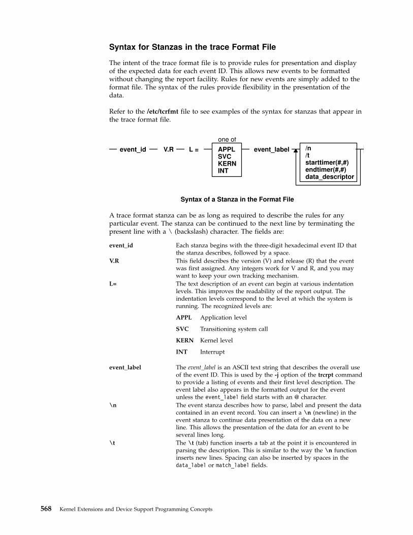
Syntax for Stanzas in the trace Format File
The intent of the trace format file is to provide rules for presentation and displayof the expected data for each event ID. This allows new events to be formattedwithout changing the report facility. Rules for new events are simply added to theformat file. The syntax of the rules provide flexibility in the presentation of thedata.
Refer to the /etc/tcrfmt file to see examples of the syntax for stanzas that appear inthe trace format file.
A trace format stanza can be as long as required to describe the rules for anyparticular event. The stanza can be continued to the next line by terminating thepresent line with a \ (backslash) character. The fields are:
event_id Each stanza begins with the three-digit hexadecimal event ID thatthe stanza describes, followed by a space.
V.R This field describes the version (V) and release (R) that the eventwas first assigned. Any integers work for V and R, and you maywant to keep your own tracking mechanism.
L= The text description of an event can begin at various indentationlevels. This improves the readability of the report output. Theindentation levels correspond to the level at which the system isrunning. The recognized levels are:
APPL Application level
SVC Transitioning system call
KERN Kernel level
INT Interrupt
event_label The event_label is an ASCII text string that describes the overall useof the event ID. This is used by the -j option of the trcrpt commandto provide a listing of events and their first level description. Theevent label also appears in the formatted output for the eventunless the event_label field starts with an @ character.
\n The event stanza describes how to parse, label and present the datacontained in an event record. You can insert a \n (newline) in theevent stanza to continue data presentation of the data on a newline. This allows the presentation of the data for an event to beseveral lines long.
\t The \t (tab) function inserts a tab at the point it is encountered inparsing the description. This is similar to the way the \n functioninserts new lines. Spacing can also be inserted by spaces in thedata_label or match_label fields.
event_id V.R L = event_label
one of
APPLSVCKERNINT
Syntax of a Stanza in the Format File
/n/tstarttimer(#,#)endtimer(#,#)data_descriptor
568 Kernel Extensions and Device Support Programming Concepts

starttimer(#,#) The starttimer and endtimer fields work together. The (#,#) field isa unique identifier that associates a particular starttimer valuewith an endtimer that has the same identifier. By convention, ifpossible, the identifiers should be the ID of starting event and theID of the ending event.
When the report facility encounters a start timer directive whileparsing an event, it associates the starting events time with theunique identifier. When an end timer with the same identifier isencountered, the report facility outputs the delta time (this appearsin brackets) that elapsed between the starting event and endingevent. The begin and end system call events make use of thiscapability. On the return from system call event, a delta time isshown that indicates how long the system call took.
endtimer(#,#) See the starttimer field in the preceding paragraph.
data_descriptor The data_descriptor field is the fundamental field that describeshow the report facility consumes, labels, and presents the data. TheSyntax of the data_descriptor Field figure illustrates this field’ssyntax.
data_label
, match_val
format
match_labeldata_descriptor
data_descriptor
Syntax of the data_descriptor Field
The various subfields of the data_descriptor field are:
data_label The data label is an ASCII string that can optionally precede theoutput of data consumed by the following format field.
format Review the format of an event record depicted in the Format of atrace Event Record figure. You can think of the report facility ashaving a pointer into the data portion of an event. This data pointeris initialized to point to the beginning of the event data (the 16-bitdata field in the hookword). The format field describes how muchdata the report facility consumes from this point and how the datais considered. For example, a value of Bm.n tells the report facilityto consume m bytes and n bits of data and to consider it as binarydata.
The possible format fields are described in the following section. Ifthis field is not followed by a comma, the report facility outputs theconsumed data in the format specified. If this field is followed by acomma, it signifies that the data is not to be displayed but insteadcompared against the following match_vals field. The datadescriptor associated with the matching match_val field is thenapplied to the remainder of the data.
match_val The match value is data of the same format described by thepreceding format fields. Several match values typically follow aformat field that is being matched. The successive match fields areseparated by commas. The last match value is not followed by acomma. Use the character string \* as a pattern-matching characterto match anything. A pattern-matching character is frequently usedas the last element of the match_val field to specify default rules ifthe preceding match_val field did not occur.
Chapter 17. Debugging Tools 569

match_label The match label is an ASCII string that is output for thecorresponding match.
Each of the possible format fields is described in the comments of the /etc/trcfmtfile. The following shows several possibilities:
Format field descriptions
Am.n This value specifies that m bytes of data are consumed as ASCII text,and that it is displayed in an output field that is n characters wide. Thedata pointer is moved m bytes.
S1, S2, S4 Left justified string. The length of the field is defined as 1 byte (S1), 2bytes (S2), or 4 bytes (S4). The data pointer is moved accordingly.
Bm.n Binary data of m bytes and n bits. The data pointer is movedaccordingly.
Xm Hexadecimal data of m bytes. The data pointer is moved accordingly.
D2, D4 Signed decimal format. Data length of 2 (D2) bytes or 4 (D4) bytes isconsumed.
U2, U4 Unsigned decimal format. Data length of 2 or 4 bytes is consumed.
F4, F8 Floating point of 4 or 8 bytes.
Gm.n Positions the data pointer. It specifies that the data pointer is positionedm bytes and n bits into the data.
Om.n Skip or omit data. It omits m bytes and n bits.
Rm Reverse the data pointer m bytes.
Some macros are provided that can be used as format fields to quickly access data.For example:
$D1, $D2, $D3, $D4, $D5 These macros access data words 1 through 5 of theevent record without moving the data pointer. The dataaccessed by a macro is hexadecimal by default. A macrocan be cast to a different data type (X, D, U, B) by usinga % character followed by the new format code. Forexample, the following macro causes data word one tobe accessed, but to be considered as 2 bytes and 3 bitsof binary data:
$D1%B2.3$HD This macro accesses the first 16 bits of data contained in
the hookword, in a similar manner as the $D1 through$D5 macros access the various data words. It is alsoconsidered as hexadecimal data, and also can be cast.
You can define other macros and use other formatting techniques in the traceformat file. This is shown in the following trace format file example.
Example Trace Format File# .# .# .## I. General Information## A. Binary format for the tracehook calls. (1 column = 4 bits)# trchk MMmTDDDD# trchkt MMmTDDDDtttttttt# trchkl MMmTDDDD11111111# trchklt MMmTDDDD11111111tttttttt# trchkg MMmTDDDD1111111122222222333333334444444455555555
570 Kernel Extensions and Device Support Programming Concepts
# trchkg MMmTDDDD1111111122222222333333334444444455555555tttttttt# trcgen MMmTLLLL11111111vvvvvvvvvvvvvvvvvvvvvvvvvvxxxxxx# trcgent MMmTLLLL11111111vvvvvvvvvvvvvvvvvvvvvvvvvvxxxxxxtttttttt## legend:# MM = major id# m = minor id# T = hooktype# D = hookdata# t = nanosecond timestamp# 1 = d1 (see trchkid.h for calling syntax for the tracehook routines)# 2 = d2, etc.# v = trcgen variable length buffer# L = length of variable length data in bytes.## The DATA_POINTER starts at the third byte in the event, ie.,# at the 16 bit hookdata DDDD.# The trcgen() type (6,7) is an exception.The DATA_POINTER starts at# the fifth byte, ie., at the 'd1' parameter 11111111.## B. Indentation levels# the left margin is set per template using the 'L=XXXX' command.# The default is L=KERN, the second column.# L=APPL moves the left margin to the first column.# L=SVC moves the left margin to the second column.# L=KERN moves the left margin to the third column.# L=INT moves the left margin to the fourth column.# The command if used must go just after the version code.## Example usage:#113 1.7 L=INT "stray interrupt" ... \## C. Continuation code and delimiters.# A '\' at the end of the line must be used to continue the template# on the next line.# Individual strings (labels) can be separated by one or more blanks# or tabs. However, all whitespace is squeezed down to 1 blank on# the report. Use '\t' for skipping to the next tabstop, or use# A0.X format (see below) for variable space.### II. FORMAT codes## A. Codes that manipulate the DATA_PONTER# Gm.n# "Goto" Set DATA_POINTER to byte.bit location m.n## Om.n# "Omit" Advance DATA_POINTER by m.n byte.bits## Rm# "Reverse" Decrement DATA_POINTER by m bytes. R0 byte aligns.## B. Codes that cause data to be output.# Am.n# Left justified ascii.# m=length in bytes of the binary data.# n=width of the displayed field.# The data pointer is rounded up to the next byte boundary.# Example# DATA_POINTER|# V# xxxxxhello world\0xxxxxx## i. A8.16 results in: |hello wo |# DATA_POINTER————|# V
Chapter 17. Debugging Tools 571
# xxxxxhello world\0xxxxxx## ii. A16.16 results in: |hello world |# DATA_POINTER————————|# V# xxxxxhello world\0xxxxxx## iii. A16 results in: |hello world|# DATA_POINTER————————|# V# xxxxxhello world\0xxxxxx## iv. A0.16 results in: | |# DATA_POINTER|# V# xxxxxhello world\0xxxxxx## S1, S2, S4# Left justified ascii string.# The length of the string is in the first byte(half-word, word)# of the data. This length of the string does not include this byte.# The data pointer is advanced by the length value.# Example# DATA_POINTER|# V# xxxxxBhello worldxxxxxx (B = hex 0x0b)## i. S1 results in: |hello world|# DATA_POINTER—————-|# V# xxxxBhello worldxxxxxx## $reg%S1# A register with the format code of 'Sx' works "backwards"# from a register with a different type. The format is Sx,# but the length of the string comes from $reg instead of the# next n bytes.## Bm.n# Binary format.# m = length in bytes# n = length in bits# The length in bits of the data is m * 8 + n. B2.3 and B0.19# are the same. Unlike the other printing FORMAT codes, the# DATA_POINTER can be bit aligned and is not rounded up to# the next byte boundary.## Xm# Hex format.# m = length in bytes. m=0 thru 16# The DATA_POINTER is advanced by m.## D2, D4# Signed decimal format.# The length of the data is 2 (4) bytes.# The DATA_POINTER is advanced by 2 (4).## U2, U4# Unsigned decimal format.# The length of the data is 2 (4) bytes.# The DATA_POINTER is advanced by 2 (4).## F4# Floating point format. (like %0.4E)# The length of the data is 4 bytes.# The format of the data is that of C type 'float'.# The DATA_POINTER is advanced by 4.
572 Kernel Extensions and Device Support Programming Concepts

## F8# Floating point format. (like %0.4E)# The length of the data is 8 bytes.# The format of the data is that of C type 'double'.# The DATA_POINTER is advanced by 8.## HB# Number of bytes in trcgen() variable length buffer.# This is also equal to the 16 bit hookdata.# The DATA_POINTER is not changed.## HT# The hooktype. (0 - E)# trcgen = 0, trchk = 1, trchl = 2, trchkg = 6# trcgent = 8, trchkt = 9, trchlt = A, trchkgt = E# HT & 0x07 masks off the timestamp bit# This is used for allowing multiple, different trchkx() calls with# the same template.# The DATA_POINTER is not changed.## C. Codes that interpret the data in some way before output.# T4# Output the next 4 bytes as a data and time string,# in GMT timezone format. (as in ctime(&seconds))# The DATA_POINTER is advanced by 4.## E1,E2,E4# Output the next byte (half_word, word) as an 'errno' value,# replacing the numeric code with the corresponding #define name in# /usr/include/sys/errno.h# The DATA_POINTER is advanced by 1, 2, or 4.## P4# Use the next word as a process id (pid), and output the# pathname of the executable with that process id.Process# ids and their pathnames are acquired by the trace command at# the start of a trace and by trcrpt via a special EXEC tracehook.# The DATA_POINTER is advanced by 4.## \t# Output a tab. \t\t\t outputs 3 tabs. Tabs are expanded to spaces,# using a fixed tabstop separation of 8.If L=0 indentation is used,# the first tabstop is at 3.# The DATA_POINTER advances over the \t.## \n# Output a newline. \n\n\n outputs 3 newlines.# The newline is left-justified according to the INDENTATION LEVEL.# The DATA_POINTER advances over the \n.## $macro# The value of 'macro' is output as a %04X value. Undefined# macros have the value of 0000.# The DATA_POINTER is not changed.# An optional format can be used with macros:# $v1%X4 will output the value $v1 in X4 format.# $zz%B0.8 will output the value $v1 in 8 bits of binary.# Understood formats are: X, D, U, B. Others default to X2.## "string" 'string' data type# Output the characters inside the double quotes exactly. A string# is treated as a descriptor. Use "" as a NULL string.## ′string format $macro′ If a string is backquoted, it is expanded# as a quoted string, except that FORMAT codes and $registers are# expanded as registers.
Chapter 17. Debugging Tools 573

## III. SWITCH statement# A format code followed by a comma is a SWITCH statement.# Each CASE entry of the SWITCH statement consists of# 1. a 'matchvalue' with a type (usually numeric) corresponding# to the format code.# 2. a simple 'string' or a new 'descriptor' bounded by braces.# A descriptor is a sequence of format codes, strings,# switches and loops.# 3. and a comma delimiter.# The switch is terminated by a CASE entry without a comma# delimiter. The CASE entry is selected to as the first# entry whose matchvalue is equal to the expansion of the format# code. The special matchvalue '\*' is a wildcard and matches# anything.# The DATA_POINTER is advanced by the format code.### IV. LOOP statement# The syntax of a 'loop' is# LOOP format_code { descriptor }# The descriptor is executed N times, where N is the numeric value# of the format code.The DATA_POINTER is advanced by the# format code plus whatever the descriptor does. Loops are used to# output binary buffers of data, so descriptor is# usually simply X1 or X0. Note that X0 is like X1 but does not# supply a space separator ' ' between each byte.## V. macro assignment and expressions# 'macros' are temporary (for the duration of that event) variables# that work like shell variables.# They are assigned a value with the syntax:# {{ $xxx = EXPR }}# where EXPR is a combination of format codes, macros, and constants.# Allowed operators are + - / *# For example:#{{ $dog = 7 + 6 }} {{ $cat = $dog * 2 }} $dog $cat## will output:#000D 001A## Macros are useful in loops where the loop count is not always# just before the data:#G1.5 {{ $count = B0.5 }} G11 LOOP $count {X0}## Up to 25 macros can be defined per template.### VI. Special macros:# $RELLINENO line number for this event. The first line starts at 1.# $D1 - $D5 dataword 1 through dataword 5. No change to datapointer.# $HD hookdata (lower 16 bits)# $SVC Output the name of the current SVC# $EXECPATH Output the pathname of the executable for current process.# $PID Output the current process id.# $ERROR Output an error message to the report and exit from the
template after the current descriptor is processed.# The error message supplies the logfile, logfile offset of# the start of that event, and the traceid.# $LOGIDX Current logfile offset into this event.# $LOGIDX0 Like $LOGIDX, but is the start of the event.# $LOGFILE Name of the logfile being processed.# $TRACEID Traceid of this event.# $DEFAULT Use the DEFAULT template 008# $STOP End the trace report right away# $BREAK End the current trace event# $SKIP Like break, but don't print anything out.
574 Kernel Extensions and Device Support Programming Concepts
# $DATAPOINTER The DATA_POINTER. It can be set and manipulated# like other user-macros.# {{ $DATAPOINTER = 5 }} is equivalent to G5# $BASEPOINTER Usually 0. It is the starting offset into an event.The# actual offset is the DATA_POINTER + BASE_POINTER. It is used# with template subroutines, where the parts on an event have# the same structure, and can be printed by the same template,# but may have different starting points into an event.## VII. Template subroutines# If a macro name consists of 3 hex digits, it is a "template# subroutine". The template whose traceid equals the macro name# is inserted in place of the macro.## The data pointer is where is was when the template# substitution was encountered.Any change made to the data pointer# by the template subroutine remains in affect when the template# ends.## Macros used within the template subroutine correspond to those# in the calling template. The first definition of a macro in the# called template is the same variable as the first in the called.# The names are not related.## Example:# Output the trace label ESDI STRATEGY.# The macro '$stat' is set to bytes 2 and 3 of the trace event.# Then call template 90F to interpret a buf header. The macro# '$return' corresponds to the macro '$rv', since they were# declared in the same order. A macro definition with# no '=' assignment just declares the name# like a place holder. When the template returns,the saved special# status word is output and the returned minor device number.##900 1.0 "ESDI STRATEGY" {{ $rv = 0 }} {{ $stat = X2 }} \# $90F \n\#special_esdi_status=$stat for minor device $rv##90F 1.0 "" G4 {{ $return }} \# block number X4 \n\# byte count X4 \n\# B0.1, 1 B_FLAG0 \# B0.1, 1 B_FLAG1 \# B0.1, 1 B_FLAG2 \# G16 {{ $return = X2 }}## Note: The $DEFAULT reserved macro is the same as $008## VII. BITFLAGS statement# The syntax of a 'bitflags' is# BITFLAGS [format_code|register],# flag_value string {optional string if false}, or# '&' mask field_value string,# ...## This statement simplifies expanding state flags, since it look# a lot like a series of #defines.# The '&' mask is used for interpreting bit fields.# The mask is anded to the register and the result is compared to# the field_value. If a match, the string is printed.# The base is 16 for flag_values and masks.# The DATA_POINTER is advanced if a format code is used.# Note:the default base for BITFLAGS is 16. If the mask or field# value has a leading 0, the number is octal. 0x or 0X makes the# number hex.# A 000 traceid will use this template
Chapter 17. Debugging Tools 575
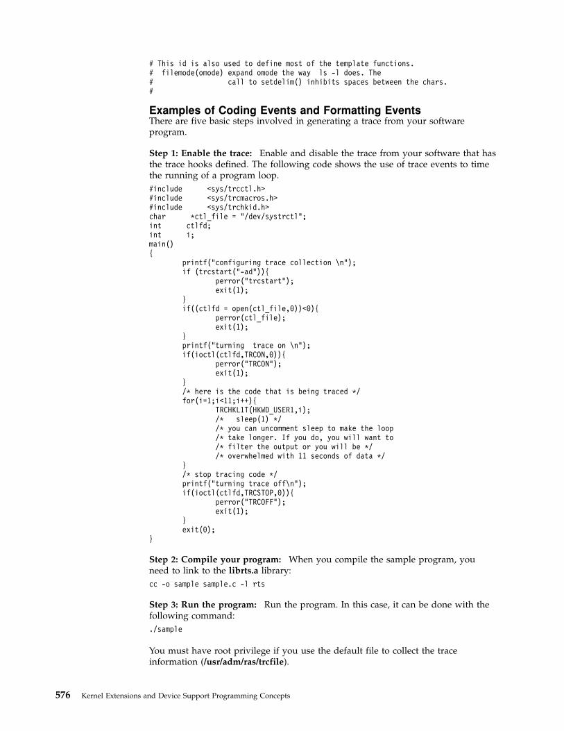
# This id is also used to define most of the template functions.# filemode(omode) expand omode the way ls -l does. The# call to setdelim() inhibits spaces between the chars.#
Examples of Coding Events and Formatting EventsThere are five basic steps involved in generating a trace from your softwareprogram.
Step 1: Enable the trace: Enable and disable the trace from your software that hasthe trace hooks defined. The following code shows the use of trace events to timethe running of a program loop.
#include <sys/trcctl.h>#include <sys/trcmacros.h>#include <sys/trchkid.h>char *ctl_file = "/dev/systrctl";int ctlfd;int i;main(){
printf("configuring trace collection \n");if (trcstart("-ad")){
perror("trcstart");exit(1);
}if((ctlfd = open(ctl_file,0))<0){
perror(ctl_file);exit(1);
}printf("turning trace on \n");if(ioctl(ctlfd,TRCON,0)){
perror("TRCON");exit(1);
}/* here is the code that is being traced */for(i=1;i<11;i++){
TRCHKL1T(HKWD_USER1,i);/* sleep(1) *//* you can uncomment sleep to make the loop/* take longer. If you do, you will want to/* filter the output or you will be *//* overwhelmed with 11 seconds of data */
}/* stop tracing code */printf("turning trace off\n");if(ioctl(ctlfd,TRCSTOP,0)){
perror("TRCOFF");exit(1);
}exit(0);
}
Step 2: Compile your program: When you compile the sample program, youneed to link to the librts.a library:
cc -o sample sample.c -l rts
Step 3: Run the program: Run the program. In this case, it can be done with thefollowing command:
./sample
You must have root privilege if you use the default file to collect the traceinformation (/usr/adm/ras/trcfile).
576 Kernel Extensions and Device Support Programming Concepts

Step 4: Add a stanza to the format file: This provides the report generator withthe information to correctly format your file. The report facility does not knowhow to format the HKWD_USER1 event, unless you provide rules in the traceformat file.
The following is an example of a stanza for the HKWD_USER1 event. TheHKWD_USER1 event is event ID 010 hexadecimal. You can verify this by lookingat the sys/trchkid.h header file.
# User event HKWD_USER1 Formatting Rules Stanza# An example that will format the event usage of the sample program010 1.0 L=APPL "USER EVENT - HKWD_USER1" O2.0 \n\
"The # of loop iterations =" U4\n\"The elapsed time of the last loop = "\endtimer(0x010,0x010) starttimer(0x010,0x010)
Note: When entering the example stanza, do not modify the master formatfile /etc/trcfmt. Instead, make a copy and keep it in your own directory. Thisallows you to always have the original trace format file available.
Step 5: Run the format/filter program: Filter the output report to get only yourevents. To do this, run the trcrpt command:
trcrpt -d 010 -t mytrcfmt -O exec=on -o sample.rpt
The formatted trace results are:
ID PROC NAME I ELAPSED_SEC DELTA_MSEC APPL SYSCALL KERNEL INTERRUPT010 sample 0.000105984 0.105984 USER HOOK 1
The data field for the user hook = 1010 sample 0.000113920 0.007936 USER HOOK 1
The data field for the user hook = 2 [7 usec]010 sample 0.000119296 0.005376 USER HOOK 1
The data field for the user hook = 3 [5 usec]010 sample 0.000124672 0.005376 USER HOOK 1
The data field for the user hook = 4 [5 usec]010 sample 0.000129792 0.005120 USER HOOK 1
The data field for the user hook = 5 [5 usec]010 sample 0.000135168 0.005376 USER HOOK 1
The data field for the user hook = 6 [5 usec]010 sample 0.000140288 0.005120 USER HOOK 1
The data field for the user hook = 7 [5 usec]010 sample 0.000145408 0.005120 USER HOOK 1
The data field for the user hook = 8 [5 usec]010 sample 0.000151040 0.005632 USER HOOK 1
The data field for the user hook = 9 [5 usec]010 sample 0.000156160 0.005120 USER HOOK 1
The data field for the user hook = 10 [5 usec]
Usage HintsThe following sections provide some examples and suggestions for use of the tracefacility.
Viewing trace DataInclude several optional columns of data in the trace output. This causes theoutput to exceed 80 columns. It is best to view the reports on an output device thatsupports 132 columns.
Bracketing Data CollectionTrace data accumulates rapidly. Bracket the data collection as closely around thearea of interest as possible. One technique for doing this is to issue severalcommands on the same command line. For example, the command:
trace -a; cp /etc/trcfmt /tmp/junk; trcstop
Chapter 17. Debugging Tools 577

captures the total execution of the copy command.
Note: This example is more educational if the source file is not alreadycached in system memory. The trcfmt file can be in memory if you have beenmodifying it or producing trace reports. In that case, choose as the source filesome other file that is 50 to 100KB and has not been touched.
Reading a trace Report
The trace facility displays system activity. It is a useful learning tool to observehow the system actually performs. The previous output is an interesting exampleto browse. To produce a report of the copy, use the following:
trcrpt -O "exec=on,pid=on" > cp.rpt
In the cp.rpt file you can see the following activities:
v The fork, exec, and page fault activities of the cp process.
v The opening of the /etc/trcfmt file for reading and the creation of the /tmp/junkfile.
v The successive read and write subroutiness to accomplish the copy.
v The cp process becoming blocked while waiting for I/O completion, and thewait process being dispatched.
v How logical volume requests are translated to physical volume requests.
v The files are mapped rather than buffered in traditional kernel buffers. The readaccesses cause page faults that must be resolved by the virtual memorymanager.
v The virtual memory manager senses sequential access and begins to prefetch thefile pages.
v The size of the prefetch becomes larger as sequential access continues.
v The writes are delayed until the file is closed (unless you captured execution ofthe sync daemon that periodically forces out modified pages).
v The disk device driver coalesces multiple file requests into one I/O request tothe drive when possible.
The trace output looks a little overwhelming at first. This is a good example to useas a learning aid. If you can discern the activities described, you are well on yourway to being able to use the trace facility to diagnose system performanceproblems.
Effective Filtering of the trace Report
The full detail of the trace data may not be required. You can choose specificevents of interest to be shown. For example, it is sometimes useful to find thenumber of times a certain event occurred. Answer the question, ″how many opensoccurred in the copy example?″ First, find the event ID for the open subroutine:
trcrpt -j | pg
You can see that event ID 15b is the open event. Now, process the data from thecopy example (the data is probably still in the log file) as follows:
trcrpt -d 15b -O "exec=on"
The report is written to standard output and you can determine the number ofopens that occurred. If you want to see only the opens that were performed by thecp process, run the report command again using:
578 Kernel Extensions and Device Support Programming Concepts

trcrpt -d 15b -p cp -O "exec=on"
This command shows only the opens performed by the cp process.
SMIT Trace Hook GroupsCombining multiple trace hooks into a trace hook group allows all hooks to beturned on at once when starting a trace.
The first item on the Start Trace menu is EVENT GROUPS to trace. The groupsthat can be traced are defined in the SWservAt ODM object class. Each group usesthe Name_trcgrpdesc and Name_trcgrp attributes. Name is the name of the tracegroup that must be no longer than 8 characters. The _trcgrpdesc attribute specifiesthe group description, and the _trcgrp attribute specifies the trace hooks in thegroup. A group can have only one _trcgrpdesc description, but it can havemultiple _trcgrp hook lists.
The following example shows the definition of the general kernel activity (gka)trace group.
SWservAt:attribute = "gka_trcgrpdesc"value = "GENERAL KERNEL ACTIVITY (files,execs,dispatches)"
SWservAt:attribute = "gka_trcgrp"value = "106,134,139,107,135,15b,12e"
Note that the value of gka_trcgrpdesc is shown by SMIT as the description of thegroup. The value list for gka_trcgrp contains the hooks in the group. You can addanother gka_trcgrp attribute to add additional trace hooks to that group. The hookids must be enclosed in double quotes (″) and separated by commas.
Memory Overlay Detection System (MODS)
AIX Kernel Memory Overlay Detection System (MODS)Some of the most difficult types of problems to debug are what are generallycalled ″memory overlays.″ Memory overlays include the following:
v Writing to memory that is owned by another program or routine
v Writing past the end (or before the beginning) of declared variables or arrays
v Writing past the end (or before the beginning) of dynamically-allocated memory
v Writing to or reading from freed memory
v Freeing memory twice
v Calling memory allocation routines with incorrect parameters or under incorrectconditions.
In the kernel environment (including the AIX kernel, kernel extensions, and devicedrivers), memory overlay problems have been especially difficult to debug becausetools for finding them have not been available. Starting with AIX Version 4.2.1,however, the Memory Overlay Detection System (MODS) helps detect memoryoverlay problems in the AIX kernel, kernel extensions, and device drivers.
Note: This feature does not detect problems in application code; it onlywatches kernel and kernel extension code.
Chapter 17. Debugging Tools 579

bosdebug commandThe bosdebug command turns the MODS facility on and off. Only the root usercan run the bosdebug command.
To turn on the base MODS support, type:
bosdebug -M
For a description of all the available options, type:
bosdebug -?
Once you have run bosdebug with the options you want, run the bosboot -acommand, then shutdown and reboot your system (using the shutdown -rcommand). If you need to make any changes to your bosdebug settings, you mustrun bosboot -a and shutdown -r again.
When to use the MODS featureThis feature is useful in the following circumstances:
v When developing your own kernel extensions or device drivers and want to testthem thoroughly.
v When asked to turn this feature on by IBM AIX service to help in furtherdiagnosing a problem that you are experiencing.
How MODS worksThe primary goal of the MODS feature is to produce a dump file that accuratelyidentifies the problem.
MODS works by turning on additional checking to help detect the conditions listedabove. When any of these conditions is detected, your system crashes immediatelyand produces a dump file that points directly at the offending code. (Previously, asystem dump might point to unrelated code that happened to be running laterwhen the invalid situation was finally detected.)
If your system crashes while the MODS is turned on, then MODS has most likelydone its job.
To make it easier to detect that this situation has occurred, the crash command hasbeen extensively modified. The stat subcommand of crash now displays both:
v Whether the MODS (also called ″xmalloc debug″) has been turned on
v Whether this crash was the result of the MODS detecting an incorrect situation.
The xmalloc subcommand provides details on exactly what memory address (ifany) was involved in the situation, and displays mini-tracebacks for the allocationand/or free of this memory.
Similarly, the netm command displays allocation and free records for memoryallocated using the net_malloc kernel service (for example, mbufs, mclusters, etc.).
You can use these commands, as well as standard crash techniques, to determineexactly what went wrong.
MODS limitationsThere are limitations to the Memory Overlay Detection System. Although itsignificantly improves your chances, MODS cannot detect all memory overlays.Also, turning MODS on has a small negative impact on overall systemperformance and causes somewhat more memory to be used in the kernel and thenetwork memory heaps. If your system is running at full CPU utilization, or if you
580 Kernel Extensions and Device Support Programming Concepts

are already near the maximums for kernel memory usage, turning on the MODSmay cause performance degradation and/or system hangs.
Our practical experience with the MODS, however, is that the great majority ofcustomers will be able to use it with minimal impact to their systems.
MODS benefitsYou’ll see these benefits from using the MODS:
v You can more easily test and debug your own kernel extensions anddevicedrivers.
v Difficult problems that once required multiple attempts to recreate and debugthem will generally require many fewer such attempts.
Chapter 17. Debugging Tools 581

582 Kernel Extensions and Device Support Programming Concepts

Appendix A. Alphabetical List of Kernel Services
This list is divided into parts based on the execution environment from which eachkernel service can be called (see “Understanding Execution Environments” onpage 7):
v “Kernel Services Available in Process and Interrupt Environments”
v “Kernel Services Available in the Process Environment Only” on page 588
“System Calls Available to Kernel Extensions” on page 31 lists the systems callsthat can be called by kernel extensions.
Kernel Services Available in Process and Interrupt Environments
add_domain_af Adds an address family to the Address Familydomain switch table.
add_input_type Adds a new input type to the Network Inputtable.
add_netisr Adds a network software interrupt service tothe Network Interrupt table.
add_netopt Adds a network option structure to the list ofnetwork options.
as_getsrval Obtains a handle to the virtual memory objectfor the specified address given in the specifiedaddress space.
bdwrite Releases the specified buffer after marking it fordelayed write.
brelse Frees the specified buffer.
_check_lock Conditionally updates a single word variableatomically, issuing an import fence formultiprocessor systems.
_clear_lock Atomically writes a single word variable,issuing an export fence for multiprocessorsystems.
clrbuf Sets the memory for the specified bufferstructure’s buffer to all zeros.
clrjmpx Removes a saved context by popping the mostrecently saved jump buffer from the list ofsaved contexts.
compare_and_swap Conditionally updates or returns a single wordvariable atomically.
curtime Reads the current time into a time structure.
d_align Assists in allocation of DMA buffers.
d_cflush Flushes the processor and I/O controller (IOCC)data caches when using the long termDMA_WRITE_ONLY mapping of DirectMemory Access (DMA) buffers approach to busdevice DMA.
d_clear Frees a DMA channel.
d_complete Cleans up after a DMA transfer.
d_init Initializes a DMA channel.
d_mask Disables a DMA channel.
d_master Initializes a block-mode DMA transfer for aDMA master.
© Copyright IBM Corp. 1997, 1999 583

d_move Provides consistent access to system memorythat is accessed asynchronously by a device andby the processor on the system.
d_roundup Assists in allocation of DMA buffers.
d_slave Initializes a block-mode DMA transfer for aDMA slave.
d_unmask Enables a DMA channel.
del_domain_af Deletes an address family from the AddressFamily domain switch table.
del_input_type Deletes an input type from the Network Inputtable.
del_netisr Deletes a network software interrupt serviceroutine from the Network Interrupt table.
del_netopt Deletes a network option structure from the listof network options.
devdump Calls a device driver dump-to-device routine.
devstrat Calls a block device driver’s strategy routine.
devswqry Checks the status of a device switch entry inthe device switch table.
disable_lock Raises the interrupt priority, and locks a simplelock if necessary.
DTOM macro Converts an address anywhere within an mbufstructure to the head of that mbuf structure.
e_clear_wait Clears the wait condition for a kernel thread.
e_wakeup, e_wakeup_one,ore_wakeup_w_result
Notifies kernel threads waiting on a sharedevent of the event’s occurrence.
e_wakeup_w_sig Posts a signal to sleeping kernel threads.
errsave and errlast Allows the kernel and kernel extensions towrite to the error log.
et_post Notifies a kernel thread of the occurrence of oneor more events.
fetch_and_add Increments a single word variable atomically.
fetch_and_and, fetch_and_or Manipulates bits in a single word variableatomically.
find_input_type Finds the given packet type in the NetworkInput Interface switch table and distributes theinput packet according to the table entry forthat type.
getc Retrieves a character from a character list.
getcb Removes the first buffer from a character listand returns the address of the removed buffer.
getcbp Retrieves multiple characters from a characterbuffer and places them at a designated address.
getcf Retrieves a free character buffer.
getcx Returns the character at the end of a designatedlist.
geterror Determines the completion status of the buffer.
getexcept Allows kernel exception handlers to retrieveadditional exception information.
getpid Gets the process ID of the current process.
i_disable Disables all of the interrupt levels at aparticular interrupt priority and all interruptlevels at a less-favored interrupt priority.
i_enable Enables all of the interrupt levels at a particularinterrupt priority and all interrupt levels at amore-favored interrupt priority.
i_mask Disables an interrupt level.
584 Kernel Extensions and Device Support Programming Concepts

i_reset Resets the system’s hardware interrupt latches.
i_sched Schedules off-level processing.
i_unmask Enables an interrupt level.
if_attach Adds a network interface to the networkinterface list.
if_detach Deletes a network interface from the networkinterface list.
if_down Marks an interface as down.
if_nostat Zeros statistical elements of the interface arrayin preparation for an attach operation.
ifa_ifwithaddr Locates an interface based on a completeaddress.
ifa_ifwithdstaddr Locates the point-to-point interface with a givendestination address.
ifa_ifwithnet Locates an interface on a specific network.
ifunit Returns a pointer to the ifnet structure of therequested interface.
io_att Selects, allocates, and maps a region in thecurrent address space for I/O access.
io_det Unmaps and deallocates the region in thecurrent address space at the given address.
iodone Performs block I/O completion processing.
kgethostname Retrieves the name of the current host.
kgettickd Retrieves the current status of the systemwidetime-of-day timer-adjustment values.
ksettickd Sets the current status of the systemwidetimer-adjustment values.
kthread_kill Posts a signal to a specified kernel thread.
loifp Returns the address of the software loopbackinterface structure.
longjmpx Allows exception handling by causing executionto resume at the most recently saved context.
looutput Sends data through a software loopbackinterface.
m_adj Adjusts the size of an mbuf chain.
m_cat Appends one mbuf chain to the end of another.
m_clattach Allocates an mbuf structure and attaches anexternal cluster.
m_clget macro Allocates a page-sized mbuf structure cluster.
m_clgetm Allocates and attaches an external buffer.
m_collapse Guarantees that an mbuf chain contains nomore than a given number of mbuf structures.
m_copy macro Creates a copy of all or part of a list of mbufstructures.
m_copydata Copies data from an mbuf chain to a specifiedbuffer.
m_copym Creates a copy of all or part of a list of mbufstructures.
m_free Frees an mbuf structure and any associatedexternal storage area.
m_freem Frees an entire mbuf chain.
m_get Allocates a memory buffer from the mbuf pool.
m_getclr Allocates and zeros a memory buffer from thembuf pool.
m_getclust macro Allocates an mbuf structure from the mbufbuffer pool and attaches a page-sized cluster.
Appendix A. Alphabetical List of Kernel Services 585

m_getclustm Allocates an mbuf structure from the mbufbuffer pool and attaches a cluster of thespecified size.
m_gethdr Allocates a header memory buffer from thembuf pool.
M_HASCL macro Determines if an mbuf structure has anattached cluster.
m_pullup Adjusts an mbuf chain so that a given numberof bytes is in contiguous memory in the dataarea of the head mbuf structure.
MTOCL macro Converts a pointer to an mbuf structure to apointer to the head of an attached cluster.
MTOD macro Converts a pointer to an mbuf structure to apointer to the data stored in that mbufstructure.
M_XMEMD macro Returns the address of an mbuf cross-memorydescriptor.
net_error Handles errors for AIX communication networkinterface drivers.
net_start_done Starts the done notification handler for AIXcommunications I/O device handlers.
net_wakeup Wakes up all sleepers waiting on the specifiedwait channel.
net_xmit Transmits data using an AIX communicationsI/O device handler.
net_xmit_trace Traces transmit packets. This kernel service wasadded for those network interfaces that choosenot to use the net_xmit kernel service to tracetransmit packets.
panic Crashes the system.
pci_cfgrw Reads and writes PCI bus slot configurationregisters.
pfctlinput Invokes the ctlinput function for eachconfigured protocol.
pffindproto Returns the address of a protocol switch tableentry.
pidsig Sends a signal to a process.
pgsignal Sends a signal to a process group.
pio_assist Provides a standardized programmed I/Oexception handling mechanism for all routinesperforming programmed I/O.
pm_planar_control Controls power of a specified device on theplanar.
pm_register_handle Registers and unregisters Power Managementhandle.
pm_register_planar_control_handle Registers and unregisters a planar controlsubroutine.
putc Places a character at the end of a character list.
putcb Places a character buffer at the end of acharacter list.
putcbp Places several characters at the end of acharacter list.
putcf Frees a specified buffer.
putcfl Frees the specified list of buffers.
putcx Places a character on a character list.
raw_input Builds a raw_header structure for a packet andsends both to the raw protocol handler.
raw_usrreq Implements user requests for raw protocols.
586 Kernel Extensions and Device Support Programming Concepts

rtalloc Allocates a route.
rtfree Frees the routing table entry.
rtinit Sets up a routing table entry, typically for anetwork interface.
rtredirect Forces a routing table entry with the specifieddestination to go through the given gateway.
rtrequest Carries out a request to change the routingtable.
_safe_fetch Atomically reads a single word variable, issuingan import fence for multiprocessor systems.
schednetisr Schedules or invokes a network softwareinterrupt service routine.
selnotify Wakes up processes waiting in a poll or selectsubroutine or the fp_poll kernel service.
setjmpx Allows saving the current execution state orcontext.
setpinit Sets the parent of the current kernel process tothe init process.
tfree Deallocates a timer request block.
timeout Schedules a function to be called after aspecified interval.
thread_self Returns the caller’s kernel thread ID.
trcgenk Records a trace event for a generic tracechannel.
trcgenkt Records a trace event, including a time stamp,for a generic trace channel.
tstart Submits a timer request.
tstop Cancels a pending timer request.
uexblock Makes a kernel thread non-runnable whencalled from a user-mode exception handler.
uexclear Makes a kernel thread blocked by the uexblockservice runnable again.
unlock_enable Unlocks a simple lock if necessary, and restoresthe interrupt priority.
unpin Unpins the address range in system (kernel)address space.
unpinu Unpins the specified address range in user orsystem memory.
untimeout Cancels a pending timer request.
vm_att Maps a specified virtual memory object to aregion in the current address space.
vm_det Unmaps and deallocates the region in thecurrent address space that contains a givenaddress.
xmdetach Detaches from a user buffer used forcross-memory operations.
xmemdma Prepares a page for DMA I/O or processes apage after DMA I/O is complete.
xmemin Performs a cross-memory move by copyingdata from the specified address space to kernelglobal memory.
xmemout Performs a cross-memory move by copyingdata from kernel global memory to a specifiedaddress space.
xmemunpin Unpins the specified address range in user orsystem memory, given a valid cross-memorydescriptor.
Appendix A. Alphabetical List of Kernel Services 587

Kernel Services Available in the Process Environment Only
as_att Selects, allocates, and maps a region in the specified addressspace for the specified virtual memory object.
as_det Unmaps and deallocates a region in the specified addressspace that was mapped with the as_att kernel service.
as_geth Obtains a handle to the virtual memory object for thespecified address given in the specified address space. Thevirtual memory object is protected.
as_puth Indicates that no more references will be made to a virtualmemory object that was obtained using the as_geth kernelservice.
as_seth Maps a specified region in the specified address space forthe specified virtual memory object
audit_svcbcopy Appends event information to the current audit event buffer.
audit_svcfinis Writes an audit record for a kernel service.
audit_svcstart Initiates an audit record for a system call.
bawrite Writes the specified buffer’s data without waiting for I/O tocomplete.
bflush Flushes all write-behind blocks on the specified device fromthe buffer cache.
binval Invalidates all of a specified device’s data in the buffercache.
bindprocessor Binds a process or thread to a processor.
blkflush Flushes the specified block if it is in the buffer cache.
bread Reads the specified block’s data into a buffer.
breada Reads in the specified block and then starts I/O on theread-ahead block.
bwrite Writes the specified buffer’s data.
cfgnadd Registers a notification routine to be called whensystem-configurable variables are changed.
cfgndel Removes a notification routine for receiving broadcasts ofchanges to system configurable variables.
copyin Copies data between user and kernel memory.
copyinstr Copies a character string (including the terminating NULLcharacter) from user to kernel space.
copyout Copies data between user and kernel memory.
creatp Creates a new kernel process.
delay Suspends the calling process for the specified number oftimer ticks.
devswadd Adds a device entry to the device switch table.
devswdel Deletes a device driver entry from the device switch table.
dmp_add Specifies data to be included in a system dump by addingan entry to the master dump table.
dmp_del Deletes an entry from the master dump table.
dmp_prinit Initializes the remote dump protocol.
e_assert_wait Asserts that the calling thread is going to sleep.
e_block_thread Blocks the calling thread.
e_sleep, e_sleepl, ore_sleep_thread
Forces the caller to wait for the occurrence of a shared event.
et_wait Forces the caller to wait for the occurrence of an event.
fp_access Checks for access permission to an open file.
fp_close Closes a file.
fp_fstat Gets the attributes of an open file.
fp_getdevno Gets the device number and/or channel number for adevice.
fp_getf Retrieves a pointer to a file structure.
588 Kernel Extensions and Device Support Programming Concepts

fp_hold Increments the open count for a specified file pointer.
fp_ioctl Issues a control command to an open device or file.
fp_llseek Changes the current offset in an open file. Used to accessoffsets beyond 2GB.
fp_lseek Changes the current offset in an open file.
fp_open Opens a regular file or directory.
fp_opendev Opens a device special file.
fp_poll Checks the I/O status of multiple file pointers/descriptorsand message queues.
fp_read Performs a read on an open file with arguments passed.
fp_readv Performs a read operation on an open file with argumentspassed in iovec elements.
fp_rwuio Performs read and write on an open file with argumentspassed in a uio structure.
fp_select Provides for cascaded, or redirected, support of the select orpoll request.
fp_write Performs a write operation on an open file with argumentspassed.
fp_writev Performs a write operation on an open file with argumentspassed in iovec elements.
fubyte Fetches, or retrieves, a byte of data from user memory.
fuword Fetches, or retrieves, a word of data from user memory.
getadsp Obtains a pointer to the current process’s address spacestructure for use with the as_att and as_det kernel services.
getblk Assigns a buffer to the specified block.
geteblk Allocates a free buffer.
getppidx Gets the parent process ID of the specified process.
getuerror Allows kernel extensions to retrieve the current value of theut_error field.
gfsadd Adds a file system type to the gfs table.
gfsdel Removes a file system type from the gfs table.
i_clear Removes an interrupt handler from the system.
i_init Defines an interrupt handler to the system, connects it to aninterrupt level, and assigns an interrupt priority to the level.
init_heap Initializes a new heap to be used with kernel memorymanagement services.
initp Changes the state of a kernel process from idle to ready.
iostadd Registers an I/O statistics structure used for updating I/Ostatistics reported by the iostat subroutine.
iostdel Removes the registration of an I/O statistics structure usedfor maintaining I/O statistics on a particular device.
iowait Waits for block I/O completion.
kmod_entrypt Returns a function pointer to a kernel module’s entry point.
kmod_load Loads an object file into the kernel or queries for an objectfile already loaded.
kmod_unload Unloads a kernel object file.
kmsgctl Provides message queue control operations.
kmsgget Obtains a message queue identifier.
kmsgrcv Reads a message from a message queue.
kmsgsnd Sends a message using a previously defined message queue.
ksettimer Sets the systemwide time-of-day timer.
kthread_start Starts a previously created kernel-only thread.
limit_sigs Changes the signal mask for the calling thread.
lock_alloc Allocates memory for a simple or complex lock.
lock_clear_recursive Prevents a complex lock from being acquired recursively.
lock_done Releases a complex lock.
lock_free Frees the memory of a simple or complex lock.
Appendix A. Alphabetical List of Kernel Services 589

lock_init Initializes a complex lock.
lock_islocked Tests whether a complex lock is locked.
lock_mine Checks whether a simple or complex lock is owned by thecaller.
lock_read, lock_try_read Locks a complex lock in shared-read mode.
lock_read_to_write,lock_try_read_to_write
Upgrades a complex lock from shared-read mode toexclusive-write mode.
lock_set_recursive Prepares a complex lock for recursive use.
lock_write, lock_try_write Locks a complex lock in exclusive-write mode.
lock_write_to_read Downgrades a complex lock from exclusive-write mode toshared-read mode.
lockl Locks a conventional process lock.
lookupvp Retrieves the vnode that corresponds to the named path.
m_dereg Deregisters expected mbuf structure usage.
m_reg Registers expected mbuf usage.
net_attach Opens a communications I/O device handler.
net_detach Closes a communications I/O device handler.
net_sleep Sleeps on the specified wait channel.
net_start Starts network IDs on a communications I/O device handler.
NLuprintf Submits a request to print an internationalized message tothe controlling terminal of a process.
pin Pins the address range in the system (kernel) space.
pincf Manages the list of free character buffers.
pincode Pins the code and data associated with an object file.
pinu Pins the specified address range in user or system memory.
prochadd Adds a systemwide process state-change notification routine.
prochdel Deletes a process state change notification routine.
purblk Invalidates a specified block’s data in the buffer cache.
rusage_incr Increments a field of the rusage structure.
setuerror Allows kernel extensions to set the ut _error field in the uarea.
sig_chk Provides the calling kernel thread the ability to poll forreceipt of signals.
sigsetmask Changes the signal mask for the calling kernel thread.
simple_lock_init Initializes a simple lock.
simple_lock, simple_lock_try Locks a simple lock.
simple_unlock Unlocks a simple lock.
sleep Forces the calling kernel thread to wait on a specifiedchannel.
subyte Stores a byte of data in user memory.
suser Determines the privilege state of a process.
suword Stores a word of data in user memory.
talloc Allocates a timer request block before starting a timerrequest.
thread_create Creates a new process thread in the calling process.
thread_setsched Sets process kernel thread scheduling parameters.
thread_terminate Terminates the calling process kernel thread.
timeoutcf Allocates or deallocates callout table entries for use with thetimeout kernel service.
uexadd Adds a systemwide exception handler for catchinguser-mode process exceptions.
uexdel Deletes a previously added systemwide user-mode exceptionhandler.
ufdcreate Provides a file interface to kernel services.
uiomove Moves a block of data between kernel space and a spacedefined by a uio structure.
590 Kernel Extensions and Device Support Programming Concepts

unlockl Unlocks a conventional process lock.
unpincode Unpins the code and data associated with an object file.
uprintf Submits a request to print a message to the controllingterminal of a process.
uphysio Performs character I/O for a block device using a uiostructure.
ureadc Writes a character to a buffer described by a uio structure.
uwritec Retrieves a character from a buffer described by a uiostructure.
vfsrele Points to a virtual file system structure.
vm_cflush Flushes the processor’s cache for a specified address range.
vm_handle Constructs a virtual memory handle for mapping a virtualmemory object with specified access level.
vm_makep Makes a page in client storage.
vm_mount Adds a file system to the paging device table.
vm_move Moves data between a virtual memory object and a bufferspecified in the uio structure.
vm_protectp Sets the page protection key for a page range.
vm_qmodify Determines whether a mapped file has been changed.
vm_release Releases virtual memory resources for the specified addressrange.
vm_releasep Releases virtual memory resources for the specified pagerange.
vm_uiomove Moves data between a virtual memory object and a bufferspecified in the uio structure.
vm_umount Removes a file system from the paging device table.
vm_write Initiates page-out for a page range in the address space.
vm_writep Initiates page-out for a page range in a virtual memoryobject.
vms_create Creates a virtual memory object of the type and size andlimits specified.
vms_delete Deletes a virtual memory object.
vms_iowait Waits for the completion of all page-out operations for pagesin the virtual memory object.
vn_free Frees a vnode previously allocated by the vn_get kernelservice.
vn_get Allocates a virtual node and inserts it into the list of vnodesfor the designated virtual file system.
waitcfree Checks the availability of a free character buffer.
w_clear Removes a watchdog timer from the list of watchdog timersknown to the kernel.
w_init Registers a watchdog timer with the kernel.
w_start Starts a watchdog timer.
w_stop Stops a watchdog timer.
xmalloc Allocates memory.
xmattach Attaches to a user buffer for cross-memory operations.
xmempin Pins the specified address range in user or system memory,given a valid cross-memory descriptor.
xmfree Frees allocated memory.
Appendix A. Alphabetical List of Kernel Services 591

592 Kernel Extensions and Device Support Programming Concepts

Index
Numerics64-bit 23
kernel extension 23
Aaccented characters 188asynchronous I/O subsystem
AIX subroutines affected by 76changing attributes in 76subroutines 75
ataide_buf structure (IDE) 291ATM LAN Emulation device driver 110
configuration parameters 113entry points 118trace and error logging 124
ATM LANEclients
adding 113attributes 94
Bblock (physical volumes) 192block device drivers
I/O kernel services 39block I/O buffer cache
managing 43supporting user access to device
drivers 42using write routines 43
block I/O buffer cache kernelservices 40
bootlist commandaltering list of boot devices 97
Ccfgmgr command
configuring devices 90, 97character I/O kernel services 40chdev command
changing device characteristics 97configuring devices 90
child devices 93clients
ATM LANEadding 113
commandscrash 303, 305, 334, 383, 388errinstall 548errlogger 553errmsg 548errpt 546, 553errupdate 549, 552, 553nm 377sysdumpdev 301sysdumpstart 302trace 556trcrpt 556, 561
communications device handlers
common entry points 100common status and exception
codes 101common status blocks 102interface kernel services 63kernel-mode interface 99mbuf structures and 101types
Ethernet 157Fiber Distributed Data Interface
(FDDI) 127Forum Compliant ATM LAN
Emulation 110Multiprotocol (MPQP) 104PCI Token-Ring High
Performance 149SOL (serial optical link) 108Token-Ring (8fa2) 140Token-Ring (8fc8) 131
user-mode interface 99
communications I/O subsystem
physical device handler model 100
compiling
when using the kernel debugger 377
configuration
low function terminal interface 185
cpu command
kernel debug program 345
crash command 303, 305, 334, 383, 388
pcb subcommand 327status subcommand 325thread subcommand 328
crash subcommands 312, 314
buf 307buffer 307callout 308cm 308cpu 309dlock 310ds 311du 312dump 312file 312fs 315hide 315inode 315kfp 315, 329knlist 316, 383le 316, 383linkblk 317mblock 318mbuf 318mst 319ndb 319nm 316, 319od 319, 334ppd 320print 321proc 321qrun 322
crash subcommands 312, 314(continued)
queue 322quit 322socket 324stack 325stat 325status 325stream 326tcb 327thread 328trace 315tty 329unhide 329user 329vfs 330vnode 330xmalloc 331
cross-memory kernel services 55
DDASD subsystem
device block level description 299device block operation
cylinder 300head 300sector 299track 300
DDS 95debugger 301, 332, 390device attributes
accessing 94modifying 95
device configuration databaseconfiguring 85customized database 84predefined database 84, 92
device configuration managerconfiguration hierarchy 85configuration rules 86device dependencies graph 86device methods and 89invoking 87
device configuration subroutines 98device configuration subsystem 84, 85
adding unsupported devices 92configuration commands 97configuration database structure
components 80device method level 84high-level perspective 83low-level perspective 84
configuration subroutines 98database configuration procedures 85device classifications 79device dependencies 93device types 87object classes in 87run-time configuration commands 90scope of support 79writing device methods for 88
© Copyright IBM Corp. 1997, 1999 593
device dependent structureformat 96updating
using the Change method 96device driver management kernel
services 46device drivers
adding 93device dependent structure 95display 187entry points 186Fibre Channel Protocol (FCP) 269interface 186pseudo
low function terminal 186device methods
Change method and device dependentstructure 96
Configure method and devicedependent structure 95
for adding devices 92for changing device states 90for changing the database and not
device state 91interfaces to
configuration manager 89run-time commands 90
invoking 88method types 88source code examples of 88writing 88
device states 90devices
child 93dependencies 93SCSI 207
devnm commandnaming devices 97
diacritics 188diagnostics
low function terminal interface 188direct access storage device
subsystem 191display device driver 187
interface 187DMA management
accessing data in progress 45hiding data 45setting up DMA transfers 44
DMA management kernel services 42dmp_add kernel service 303dmp_del kernel service 303dump 301, 332, 390
system 301
Eentry points
communications physical devicehandler 100
device driver 186IDE adapter device driver 294IDE device driver 294logical volume device driver 196MPQP device handler 104SCSI adapter device driver 227SCSI device driver 227
entry points (continued)SOL device handler 108
errinstall command 548errlogger command 553errmsg command 548error logging 546
adding logging calls 552coding steps 548
error record template 549errpt command 546, 553errsave kernel service 546, 552, 553errupdate command 549, 552, 553Ethernet device driver 157
asynchronous status 166configuration parameters 159device control operations 168entry points 164trace and error logging 171
exception codescommunications device handlers 101
exception handlersimplementing
in kernel-mode 20, 21, 22in user-mode 23
exception handlinginterrupts and exceptions 18modes
kernel 18user 23
processing exceptionsbasic requirements 19default mechanism 18kernel-mode 18
exception management kernelservices 63
execution environmentsinterrupt 8process 8
FFDDI device driver 127
configuration parameters 127entry points 128trace and error logging 129
Fiber Distributed Data Interface devicedriver 127
Fibre Channel Protocol (FCP) 269file descriptor 51file systems
logical file system 33virtual file system 35
files
/dev/error 546, 553/dev/mem 305/dev/systrctl 557, 559, 560/etc/trcfmt 561, 577/usr/adm/ras/trcfile 557/usr/lib/boot/unix 305sys/buf.h 307sys/dump.h 303, 305sys/erec.h 551sys/err_rec.h 553sys/errids.h 552sys/file.h 312sys/proc.h 301, 321sys/socket.h 324
files (continued)sys/timer.h 308sys/trcctl.h 560sys/trchkid.h 565, 566, 577sys/trcmacros.h 565sys/tty.h 329sys/user.h 301sys/vfs.h 330sys/vnode.h 331
filesystem 33find command for the kernel debug
program 348fine granularity timer services
coding the timer function 68Forum Compliant ATM LAN Emulation
device driver 110
Gg-nodes 35getattr subroutine
modifying attributes 95go command for kernel debug
program 350graphic input device 179
Hhardware interrupt kernel services 40hlpwatch 376
II/O kernel services
block I/O 39buffer cache 40character I/O 40DMA management 42interrupt management 40memory buffer (mbuf) 41
iddebug 371, 372
IDE subsystem
adapter device driverentry points 294ioctl commands 295ioctl operations 296, 297, 298performing dumps 294
device communicationinitiator-mode support 286
error processing 294error recovery
analyzing returned status 286initiator mode 286
IDE device driverdesign requirements 293entry points 294internal commands 288responsibilities relative to adapter
device driver 285initiator I/O request execution
fragmented commands 290gathered write commands 290spanned or consolidated
commands 288structures
ataide_buf structure 291
594 Kernel Extensions and Device Support Programming Concepts

IDE subsystem (continued)typical adapter transaction
sequence 287
input device, subsystem 179
input ring mechanism 186
interface
low function terminal subsystem 185
interrupt execution environment 8
interrupt management
defining levels 44setting priorities 44
interrupt management kernelservices 44
interrupts
management services 40
KKDB Kernel Debugger 390
example files 542, 544, 546introduction 390subcommands 394
kernel debug program 355
address origin, setting 354address register
instruction, increasing 354address register, instruction
decreasing 342breakpoints
clearing 344listing 343setting 342skipping, restarting after 351
cpu command 345create and change
values 361data screens, displaying 359data storing 364device drivers, displaying 347displays
memory segments 360displays contents of STREAMS 353displays data structure 354displays floating-point registers 349displays internal file system
tables 350displays internal STREAMS 346displays reason 357displays STREAMS queues 356displays structure of 64-bit
process 353ending the program session 357error messages 388floating point registers,
displaying 349formatted process tables,
displaying 355formatted trace buffers,
displaying 370fullwords, storing into memory 363halfwords, storing 365help screen, displaying 351instruction address register
decreasing 342increasing 354
loading 333
kernel debug program 355 (continued)memory
storing fullwords into 363memory, displaying 345memory location, altering 341per-processor data, displaying 355processor, switching 345program, restarting 350reboots machine 358RS-232 port, switching 367segment registers, displaying 362,
366single-stepping instructions 365stack traceback
formatted, tracing 364starting 333statistics
diplays 344storage, searching 348storing data 364storing halfwords 365system load list, displaying 352thread command 369thread table, displaying 368timer request blocks, displaying 371translating
virtual address to realaddress 376
tty command 372tty structure
displaying 371u-area, displaying 372un
displays 372user-defined variables, clearing 358user-defined variables,
displaying 375user64 area, displaying 373uthread command 374uthread structure, displaying 373variables
user-defined, clearing 358variables, user-defined 375virtual memory, displaying 375
kernel debug program commands
alter 341back 342break 342breaks 343buckets 344clear 344cpu 345create and change 361display
displaying memory 345internal STREAMS 346
displays64-bit process 353contents of STREAMS 353data structure 354internal file system tables 350internal STREAMS 349memory segmetns 360reason for entering debugger 357STREAMS queues 356
drivers 347find 348
kernel debug program commands(continued)
float 349go 350help 351loop 351map 352next 354origin 354proc 355quit 357reboots 358reset 358screen 359sr64 362, 366sregs 362st 363stack 364stc 364step 365sth 365swap 367trace 370trb 371tty 371un 372user
displaying u-area 372displaying user64 area 373
vars 375vmm 375watch 376xlate 376
kernel debugger
accessing global data 384compiler listings 377compiling options 377displaying registers 386entering 334KDB 390LLDB 332map files 378setting breakpoints 338, 381stack trace 387subcommands 335
breakpoints 338dereferencing a pointer 337expressions 337reserved variables 336variables 335
kernel environment 1
base kernel services 2creation of kernel processes 11exception handling 18exception processing in
exception and process kernelservices 63
execution environmentsinterrupt 8process 8
librarieslibcsys 6libsys 7
loading system calls and kernelservices 3
private routines 4
Index 595

kernel environment 1 (continued)programming
kernel threads 9kernel environment, runtime 39kernel extension binding
adding symbols to the /unix namespace 2
using existing libraries 5using private routines 4
kernel extension development
64-bit 23
kernel extension libraries
libcsys 6libsys 7
kernel extension management kernelservices 46
kernel extensions
accessing user-mode datausing cross-memory services 16using data transfer services 15
interrupt priorityservice times 44
loading and binding services 46management services 47serializing access to data
structures 16using with system calls 3
kernel processes
accessing data from 12comparison to user processes 11creating 13executing 13handling exceptions 14handling signals 14obtaining cross-memory
descriptors 13preempting 14terminating 13using system calls 15
kernel protection domain 11, 12
kernel services 39, 46
categoriesatomic operations 50, 51complex locks 49device driver management 46, 47exception management 63I/O 39, 40, 41, 42kernel extension management 46,
47lock allocation 48locking 48logical file system 51memory 53, 54, 55message queue 60network 61, 62, 63process level locks 50process management 63Reliability Availability
Serviceability (RAS) 66security 67simple locks 48time-of-day 67timer 67, 68virtual file system 69
dmp_add 303dmp_del 303errsave 546, 552, 553
kernel services 39, 46 (continued)loading
with system calls 3multiprocessor-safe timer service 69unloading
with system calls 4kernel threads
creating 10executing 10terminating 10
Llft 185LFT
accented characters 188libraries
libcsys 6libsys 7
LLDB Kernel Debugger 332commands 338
lockingconventional locks 16kernel-mode strategy 17serializing access to a predefined data
structure and 16locking kernel services 48logical file system
component structurefile routines 34system calls 34v-nodes 35
file system role 33logical file system kernel services 51logical volume device driver
bottom half 196data structures 195physical device driver interface 198pseudo-device driver role 195top half 196
logical volume managerchanging the mwcc_entries
variable 200DASD support 191
logical volume subsystembad block processing 199logical volume device driver 195physical volumes
comparison with logicalvolumes 191
reserved sectors 192loop command for the kernel debug
program 351loopback kernel services 62low function terminal
configuration commands 186functional description 185interface 185
components 186configuration 185device driver entry points 186ioctls 186terminal emulation 185to display device drivers 186to system keyboard 186
low function terminal interface
AIXwindow support 186
low function terminal subsystem 185accented characters supported 188
lsattr commanddisplaying attribute characteristics of
devices 97lscfg command
displaying device diagnosticinformation 98
lsconn commanddisplaying device connections 97
lsdev commanddisplaying device information 97
lsparent commanddisplaying information about parent
devices 97LVM 200
Mmacros
memory buffer (mbuf) 41management services
file descriptor 51map command 352mbuf structures
communications device handlersand 101
memory buffer (mbuf) kernelservices 41
memory buffer (mbuf) macros 41memory kernel services
memory management 53memory pinning 53user memory access 54
message queue kernel services 60Micro Channel adapters
displaying registers 386mirror write consistency cache (LVM)
changing the value 200mkdev command
adding devices to the system 97configuring devices 90
mknod commandcreating special files 98
MODS 579MPQP device handlers
binary synchronous communicationmessage types 104receive errors 105
card descriptionhardware specifications 105modem interfaces 107physical interface mapping 108port interfaces 106
entry points 104multiprocessor-safe timer services,
using 69Multiprotocol device handlers 104
Nnetwork kernel services
address family domain 61communications device handler
interface 63interface address 62loopback 62
596 Kernel Extensions and Device Support Programming Concepts

network kernel services (continued)network interface device driver 61protocol 62routing 62
nm command 377
Oobject data manager 92ODM 92odmadd command
adding devices to predefineddatabase 92
optical link device handlers 108
Ppartition (physical volumes) 192PCI Token-Ring Device Driver
trace and error logging 155PCI Token-Ring High Device Driver
entry points 151PCI Token-Ring High Performance
configuration parameters 150PCI Token-Ring High Performance
Device Driver 149performance tracing 301, 332, 390physical volumes
block 192comparison with logical volumes 191limitations 192partition 192reserved sectors 192sector layout 192
pinningmemory 53
ppd command 355predefined attributes object class
accessing 94modifying 95
printer addition management subsystemadding a printer definition 204adding a printer formatter 205adding a printer type 203defining embedded references in
attribute strings 205modifying printer attributes 204
printer formatterdefining embedded references 205
printersunsupported types 203
private routines 4process execution environment 8process management kernel services 63pseudo device driver
low function terminal 186putattr subroutine
modifying attributes 95
RRCM 187
referenced routines
for memory pinning 59to support address space
operations 59
referenced routines (continued)to support cross-memory
operations 59to support pager back ends 59
Reliability Availability Serviceability(RAS) kernel services 66
rendering context manager 186, 187restbase command
restoring customized information toconfiguration database 97
rmdev commandconfiguring devices 90removing devices from the
system 97runtime kernel environment 39
Ssample code
trace format file 570savebase command
saving customized information toconfiguration database 97
sc_buf structure (SCSI) 218SCSI subsystem
adapter device driverentry points 227ioctl commands 235, 237, 239ioctl operations 232, 236, 237, 238,
239performing dumps 228responsibilities relative to SCSI
device driver 207asynchronous event handling 209command tag queuing 218device communication
initiator-mode support 208target-mode support 208
error processing 227error recovery
initiator mode 211target mode 214
initiator I/O request executionfragmented commands 216gathered write commands 217spanned or consolidated
commands 215initiator-mode adapter transaction
sequence 214SCSI device driver
asynchronous event-handlingroutine 210
closing a device 227design requirements 223entry points 227internal commands 215responsibilities relative to adapter
device driver 207using openx subroutine
options 223structures
sc_buf structure 218tm_buf structure 227, 232
target-mode interface 229, 231, 233interaction with initiator-mode
interface 229security kernel services 67serial optical link device handlers 108
Small Computer Systems Interfacesubsystem 207
SOL device handlerschanging device attributes 110configuring physical and logical
devices 109entry points 108special files interfaces 108
status and exception codes 101status blocks
communications device handlerCIO_ASYNC_STATUS 103CIO_HALT_DONE 102CIO_LOST_STATUS 103CIO_NULL_BLK 103CIO_START_DONE 102CIO_TX_DONE 103
communications device handlersand 102
status codescommunications device handlers
and 101storage 191stream-based tty subsystem 185
subroutines
sysconfig 382
subsystem
low function terminal 185streams-based tty 185
subsysten
graphic input device 179
sysconfig subroutine 382
sysdumpdev command 301
sysdumpstart command 302
system calls
accessing kernel data fromdata types 27passing parameters 27
error information 31exception handling
alternatives 30default mechanism 29
extending the kernel withcall handler actions 26execution 25
in kernel protection domain 26in user protection domain 26loading
with kernel services 3nesting for kernel-mode use 30preempting 28response to page faulting 30services for all kernel extensions 31services for kernel processes only 32signal handling in
asynchronous signals 29setjmpx kernel service 29signal delivery 28stacking saved contexts 29wait termination 29
unloadingwith kernel services 4
using with kernel extensions 3
system dump 301
formatting 304including device driver
information 302
Index 597
system dump 301 (continued)initiating 301
system dumpcomponentscomponent dump table 302master dump table 302
Tterminal emulation
low function terminal 185thread command
kernel debug program 369time-of-day kernel services 67timer kernel services
coding the timer function 69compatibility 68determining the timer service to
use 68fine granularity 67reading time into time structure 68watchdog 68
timer servicemultiprocessor-safe, using 69
tm_buf structure (SCSI) 227Token-Ring (8fa2) device driver 140, 141
configuration parameters 141trace and error logging 147
Token-Ring (8fc8) device 131Token-Ring (8fc8) device driver 132
configuration parameters 132trace and error logging 138
trace command 556trace events
defining 564event IDs 566
determining location of 566format file example 570format file stanzas 568forms 564macros 565
trace reportfiltering 578producing 561reading 578
tracing 554configuring 556controlling 559starting 554, 556
trcrpt command 556, 561tty command
kernel debug program 372
Uuser commands
configuration 186uthread command
kernel debug program 374
Vv-nodes 35
virtual file system 33
configuring 38data structures 36, 37file system role 35
virtual file system 33 (continued)generic nodes (g-nodes) 35header files 37interface requirements 36mount points 35virtual nodes (v-nodes) 35
virtual file system kernel services 69
virtual memory management
addressing data 57data flushing 57discarding data 57executing data 58installing pager backends 58moving data to or from an object 57objects 56protecting data 58referenced routines
for manipulating objects 58, 59virtual memory manager 56
virtual memory management kernelservices 54
vm_uiomove 55, 57, 59, 591
598 Kernel Extensions and Device Support Programming Concepts

Vos remarques sur ce document / Technical publication remark form
Titre / Title : Bull Kernel Extensions and Device Support Programming Concepts
Nº Reférence / Reference Nº : 86 A2 36JX 02 Daté / Dated : November 1999
ERREURS DETECTEES / ERRORS IN PUBLICATION
AMELIORATIONS SUGGEREES / SUGGESTIONS FOR IMPROVEMENT TO PUBLICATION
Vos remarques et suggestions seront examinées attentivement.
Si vous désirez une réponse écrite, veuillez indiquer ci-après votre adresse postale complète.
Your comments will be promptly investigated by qualified technical personnel and action will be taken as required.
If you require a written reply, please furnish your complete mailing address below.
NOM / NAME : Date :
SOCIETE / COMPANY :
ADRESSE / ADDRESS :
Remettez cet imprimé à un responsable BULL ou envoyez-le directement à :
Please give this technical publication remark form to your BULL representative or mail to:
BULL ELECTRONICS ANGERS
CEDOC
34 Rue du Nid de Pie – BP 428
49004 ANGERS CEDEX 01
FRANCE

Technical Publications Ordering Form
Bon de Commande de Documents Techniques
To order additional publications, please fill up a copy of this form and send it via mail to:
Pour commander des documents techniques, remplissez une copie de ce formulaire et envoyez-la à :
BULL ELECTRONICS ANGERSCEDOCATTN / MME DUMOULIN34 Rue du Nid de Pie – BP 42849004 ANGERS CEDEX 01FRANCE
Managers / Gestionnaires :Mrs. / Mme : C. DUMOULIN +33 (0) 2 41 73 76 65Mr. / M : L. CHERUBIN +33 (0) 2 41 73 63 96
FAX : +33 (0) 2 41 73 60 19E–Mail / Courrier Electronique : [email protected]
Or visit our web site at: / Ou visitez notre site web à:
http://www–frec.bull.com (Press Room, Technical Literature, Ordering Publications)
CEDOC Reference #No Référence CEDOC
QtyQté
CEDOC Reference #No Référence CEDOC
QtyQté
CEDOC Reference #No Référence CEDOC
QtyQté
_ _ _ _ _ _ _ _ _ [ _ _ ] _ _ _ _ _ _ _ _ _ [ _ _ ] _ _ _ _ _ _ _ _ _ [ _ _ ]
_ _ _ _ _ _ _ _ _ [ _ _ ] _ _ _ _ _ _ _ _ _ [ _ _ ] _ _ _ _ _ _ _ _ _ [ _ _ ]
_ _ _ _ _ _ _ _ _ [ _ _ ] _ _ _ _ _ _ _ _ _ [ _ _ ] _ _ _ _ _ _ _ _ _ [ _ _ ]
_ _ _ _ _ _ _ _ _ [ _ _ ] _ _ _ _ _ _ _ _ _ [ _ _ ] _ _ _ _ _ _ _ _ _ [ _ _ ]
_ _ _ _ _ _ _ _ _ [ _ _ ] _ _ _ _ _ _ _ _ _ [ _ _ ] _ _ _ _ _ _ _ _ _ [ _ _ ]
_ _ _ _ _ _ _ _ _ [ _ _ ] _ _ _ _ _ _ _ _ _ [ _ _ ] _ _ _ _ _ _ _ _ _ [ _ _ ]
_ _ _ _ _ _ _ _ _ [ _ _ ] _ _ _ _ _ _ _ _ _ [ _ _ ] _ _ _ _ _ _ _ _ _ [ _ _ ]
[ _ _ ] : no revision number means latest revision / pas de numéro de révision signifie révision la plus récente
NOM / NAME : Date :
SOCIETE / COMPANY :
ADRESSE / ADDRESS :
PHONE / TELEPHONE : FAX :
E–MAIL :
For Bull Subsidiaries / Pour les Filiales Bull :
Identification:
For Bull Affiliated Customers / Pour les Clients Affiliés Bull :
Customer Code / Code Client :
For Bull Internal Customers / Pour les Clients Internes Bull :
Budgetary Section / Section Budgétaire :
For Others / Pour les Autres :
Please ask your Bull representative. / Merci de demander à votre contact Bull.


BULL ELECTRONICS ANGERS
CEDOC
34 Rue du Nid de Pie – BP 428
49004 ANGERS CEDEX 01
FRANCE
86 A2 36JX 02
ORDER REFERENCE
PLA
CE
BA
R C
OD
E I
N L
OW
ER
LE
FT
CO
RN
ER

Utiliser les marques de découpe pour obtenir les étiquettes.
Use the cut marks to get the labels.
86 A2 36JX 02
Kernel Extensionsand Device
SupportProgramming
Concepts
86 A2 36JX 02
Kernel Extensionsand Device
SupportProgramming
Concepts
86 A2 36JX 02
Kernel Extensionsand Device
SupportProgramming
Concepts