ken youssefi engineering 10, sjsu 1 the blade shape design groups should conduct a thorough search...
Post on 22-Dec-2015
217 views
TRANSCRIPT
Ken Youssefi Engineering 10, SJSU 1
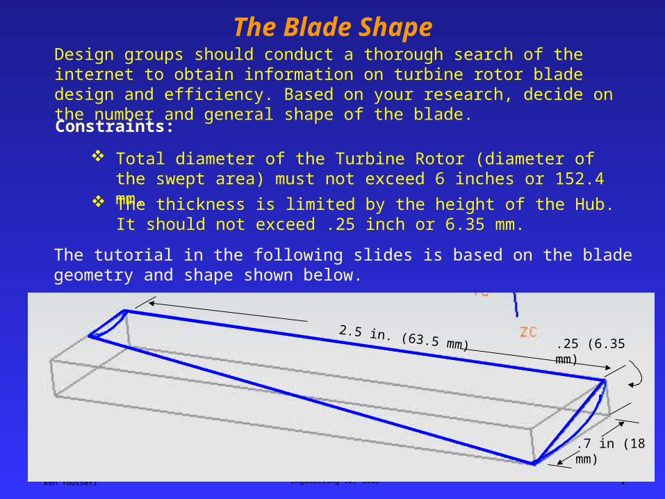
The Blade ShapeDesign groups should conduct a thorough search of the internet to obtain information on turbine rotor blade design and efficiency. Based on your research, decide on the number and general shape of the blade.
Constraints:
Total diameter of the Turbine Rotor (diameter of the swept area) must not exceed 6 inches or 152.4 mm.
The thickness is limited by the height of the Hub. It should not exceed .25 inch or 6.35 mm.
The tutorial in the following slides is based on the blade geometry and shape shown below.
.7 in (18 mm)
.25 (6.35 mm)2.5 in. (63.5 mm)
Ken Youssefi Engineering 10, SJSU 2
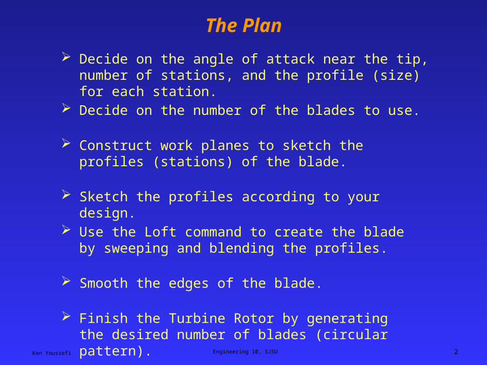
The Plan
Decide on the angle of attack near the tip, number of stations, and the profile (size) for each station.
Construct work planes to sketch the profiles (stations) of the blade.
Sketch the profiles according to your design.
Use the Loft command to create the blade by sweeping and blending the profiles.
Smooth the edges of the blade.
Finish the Turbine Rotor by generating the desired number of blades (circular pattern).
Decide on the number of the blades to use.
Ken Youssefi Engineering 10, SJSU 3
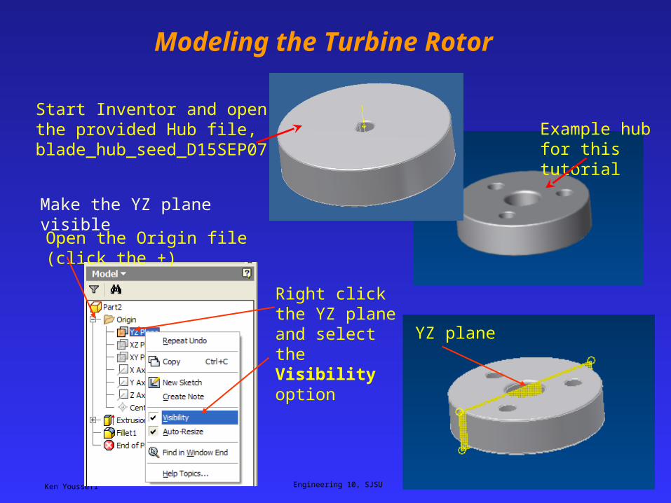
Modeling the Turbine Rotor
Start Inventor and open the provided Hub file, blade_hub_seed_D15SEP07
Make the YZ plane visible
Open the Origin file (click the +)
Right click the YZ plane and select the Visibility option
YZ plane
Example hub for this tutorial
Ken Youssefi Engineering 10, SJSU 4
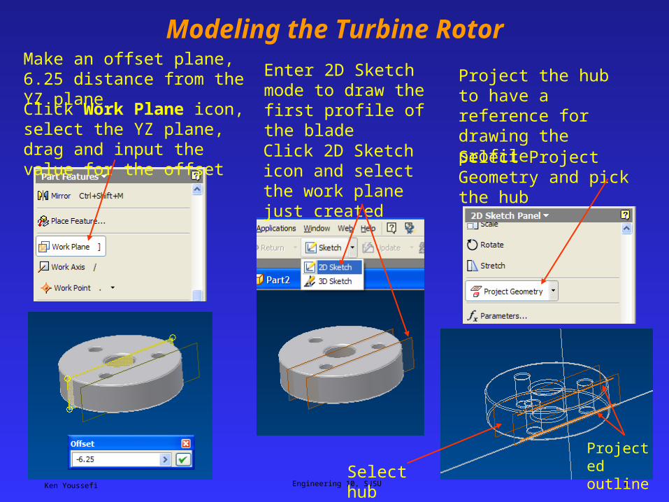
Modeling the Turbine RotorMake an offset plane, 6.25 distance from the YZ plane
Click Work Plane icon, select the YZ plane, drag and input the value for the offset
Project the hub to have a reference for drawing the profile
Select Project Geometry and pick the hub
Projected outlineSelect hub
Enter 2D Sketch mode to draw the first profile of the blade
Click 2D Sketch icon and select the work plane just created
Ken Youssefi Engineering 10, SJSU 5
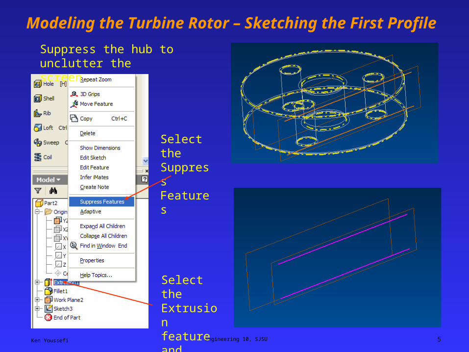
Modeling the Turbine Rotor – Sketching the First Profile
Suppress the hub to unclutter the screen
Select the Extrusion feature and right click
Select the Suppress Features
Ken Youssefi Engineering 10, SJSU 6
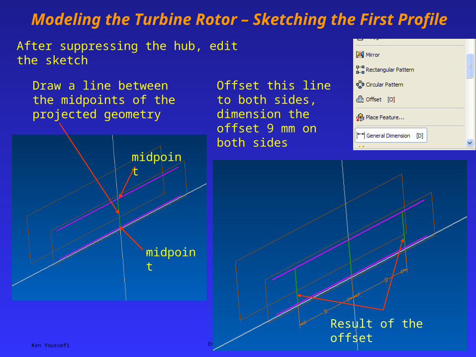
Modeling the Turbine Rotor – Sketching the First Profile
Draw a line between the midpoints of the projected geometry
After suppressing the hub, edit the sketch
midpoint
midpoint
Offset this line to both sides, dimension the offset 9 mm on both sides
Result of the offset
Ken Youssefi Engineering 10, SJSU 7
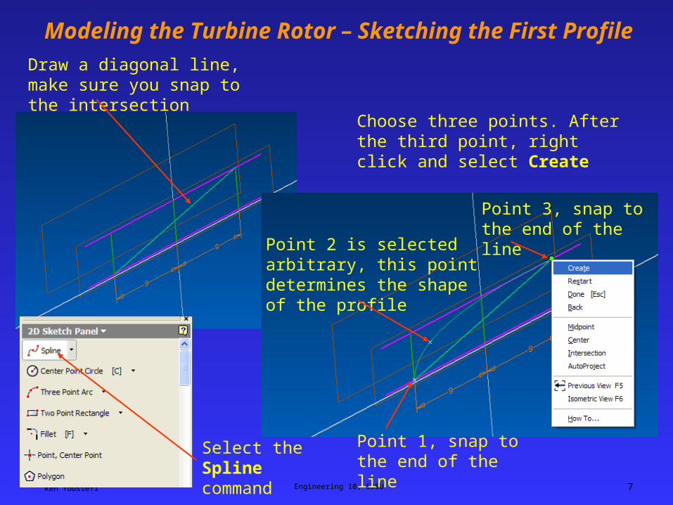
Modeling the Turbine Rotor – Sketching the First Profile
Draw a diagonal line, make sure you snap to the intersection
Select the Spline command
Choose three points. After the third point, right click and select Create
Point 1, snap to the end of the line
Point 2 is selected arbitrary, this point determines the shape of the profile
Point 3, snap to the end of the line
Ken Youssefi Engineering 10, SJSU 8
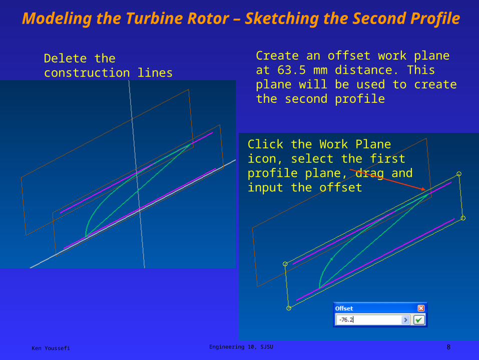
Modeling the Turbine Rotor – Sketching the Second Profile
Delete the construction lines Create an offset work plane at 63.5 mm distance. This plane will be used to create the second profile
Click the Work Plane icon, select the first profile plane, drag and input the offset
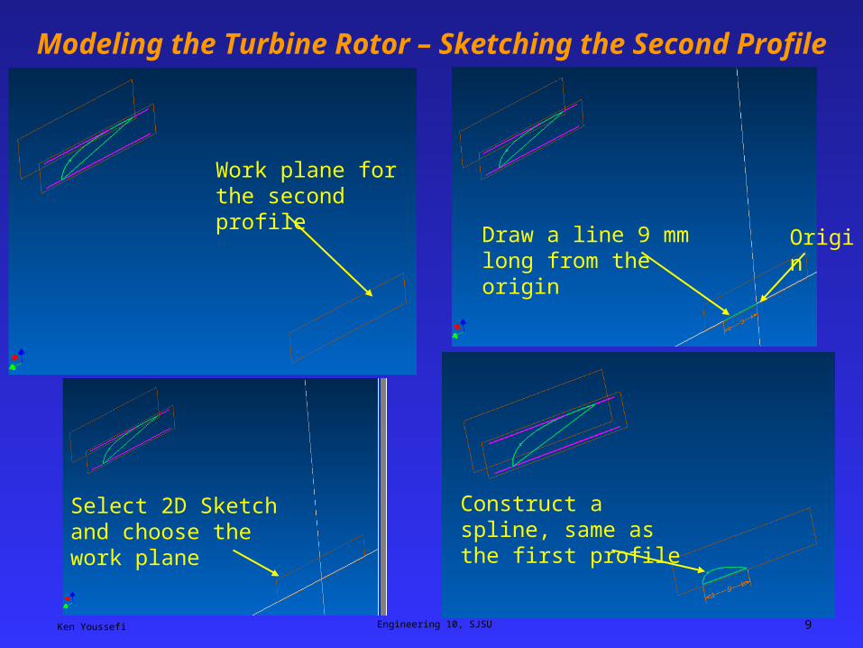
Ken Youssefi Engineering 10, SJSU 9
Modeling the Turbine Rotor – Sketching the Second Profile
Work plane for the second profile
Select 2D Sketch and choose the work plane
Draw a line 9 mm long from the origin
Origin
Construct a spline, same as the first profile
Ken Youssefi Engineering 10, SJSU 10
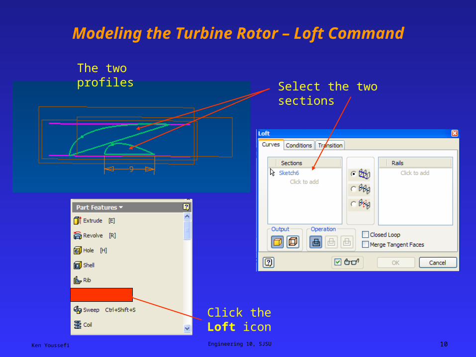
Modeling the Turbine Rotor – Loft Command
The two profiles
Click the Loft icon
Select the two sections
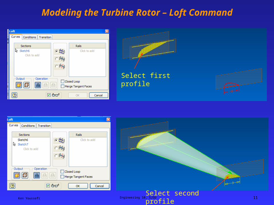
Ken Youssefi Engineering 10, SJSU 11
Modeling the Turbine Rotor – Loft Command
Select first profile
Select second profile
Ken Youssefi Engineering 10, SJSU 12
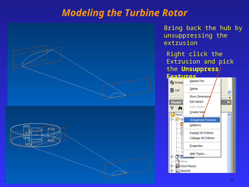
Modeling the Turbine Rotor
Bring back the hub by unsuppressing the extrusion
Right click the Extrusion and pick the Unsuppress Features
Ken Youssefi Engineering 10, SJSU 13
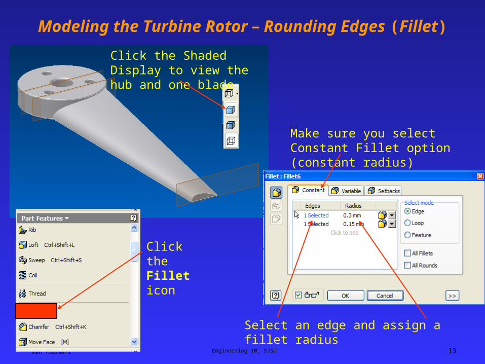
Modeling the Turbine Rotor – Rounding Edges (Fillet)
Click the Shaded Display to view the hub and one blade
Click the Fillet icon
Make sure you select Constant Fillet option (constant radius)
Select an edge and assign a fillet radius
Ken Youssefi Engineering 10, SJSU 14
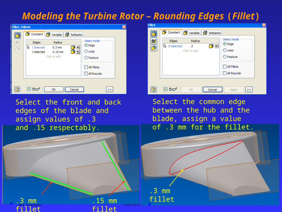
Modeling the Turbine Rotor – Rounding Edges (Fillet)
Select the front and back edges of the blade and assign values of .3 and .15 respectably.
.3 mm fillet .15 mm fillet
Select the common edge between the hub and the blade, assign a value of .3 mm for the fillet.
.3 mm fillet
Ken Youssefi Engineering 10, SJSU 15
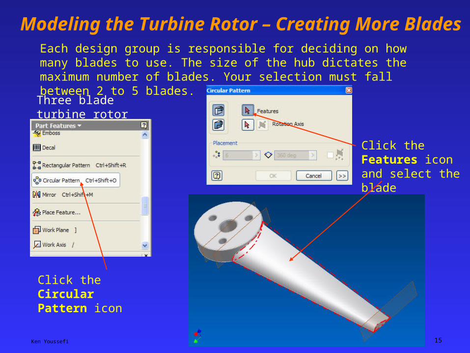
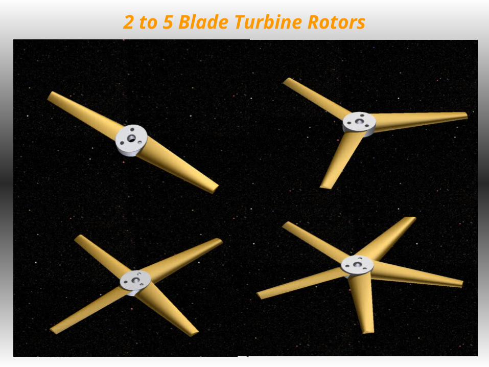
Modeling the Turbine Rotor – Creating More BladesEach design group is responsible for deciding on how many blades to use. The size of the hub dictates the maximum number of blades. Your selection must fall between 2 to 5 blades.
Click the Features icon and select the blade
Three blade turbine rotor
Click the Circular Pattern icon
Ken Youssefi Engineering 10, SJSU 16
Modeling the Turbine Rotor – Creating More Blades
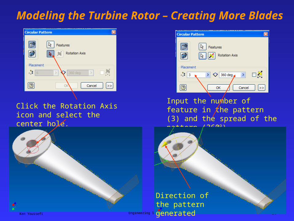
Click the Rotation Axis icon and select the center hole.
Input the number of feature in the pattern (3) and the spread of the pattern (360o).
Direction of the pattern generated
Ken Youssefi Engineering 10, SJSU 17
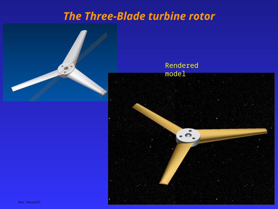
The Three-Blade turbine rotor
Rendered model
Ken Youssefi Engineering 10, SJSU 18
2 to 5 Blade Turbine Rotors