ken toolingsystems11 l000 l001.qxp:widia 11:41 …€¦ · da 01 double angle locknuts ... shell...
TRANSCRIPT

KEN_TOOLINGSYSTEMS11_L000_L001.qxp:WIDIA 11:41 AM Page L2

Shrink Fit Unit Offering . . . . . . . . . . . . . . . . . . . . . . . . . . . . . . . . . . . . . . . . . . . . . . . . . . . . . . . . . . . .L2Induction Shrink Fit Unit TTISG3400EU . . . . . . . . . . . . . . . . . . . . . . . . . . . . . . . . . . . . . . . . . . . .L4–L7Induction Shrink Fit Unit TTISG3400NA . . . . . . . . . . . . . . . . . . . . . . . . . . . . . . . . . . . . . . . . . . . .L4–L7Induction Shrink Fit Unit TTISG3400CCEU . . . . . . . . . . . . . . . . . . . . . . . . . . . . . . . . . . . . . . . .L8–L11Induction Shrink Fit Unit TTISG3400CCNA . . . . . . . . . . . . . . . . . . . . . . . . . . . . . . . . . . . . . . . .L8–L11Shrink Fit Axial Adjustment Gages . . . . . . . . . . . . . . . . . . . . . . . . . . . . . . . . . . . . . . . . . . . . . .L12–L13Balance Screw Sets . . . . . . . . . . . . . . . . . . . . . . . . . . . . . . . . . . . . . . . . . . . . . . . . . . . . . . . . . . . . . .L14HC Hydraulic Chuck Test Pins . . . . . . . . . . . . . . . . . . . . . . . . . . . . . . . . . . . . . . . . . . . . . . . . . . . . .L14HC Hydraulic Chuck Cleaning Brushes . . . . . . . . . . . . . . . . . . . . . . . . . . . . . . . . . . . . . . . . . . . . . .L15Collet Extractors TG . . . . . . . . . . . . . . . . . . . . . . . . . . . . . . . . . . . . . . . . . . . . . . . . . . . . . . . . . . . . . .L15TG Round Flush-Face Locknuts . . . . . . . . . . . . . . . . . . . . . . . . . . . . . . . . . . . . . . . . . . . . . . . . . . . .L16TG Balanceable Round Locknuts . . . . . . . . . . . . . . . . . . . . . . . . . . . . . . . . . . . . . . . . . . . . . . . . . . .L16Coolant Disk Assemblies . . . . . . . . . . . . . . . . . . . . . . . . . . . . . . . . . . . . . . . . . . . . . . . . . . . . . . . . . .L17TG Standard Round and Hex Locknuts . . . . . . . . . . . . . . . . . . . . . . . . . . . . . . . . . . . . . . . . . . . . . .L18ER Standard Short and Slim Locknuts . . . . . . . . . . . . . . . . . . . . . . . . . . . . . . . . . . . . . . . . . . . . . . .L19ER Slim Coolant and Hex Locknuts . . . . . . . . . . . . . . . . . . . . . . . . . . . . . . . . . . . . . . . . . . . . . . . . .L20ER Coolant Hex and Standard Round Locknuts . . . . . . . . . . . . . . . . . . . . . . . . . . . . . . . . . . . . . . .L21ER Coolant Round Locknuts . . . . . . . . . . . . . . . . . . . . . . . . . . . . . . . . . . . . . . . . . . . . . . . . . . . . . . .L22Coolant Locknut Sealing Disks and Disk Sets . . . . . . . . . . . . . . . . . . . . . . . . . . . . . . . . . . . .L23–L29
ER16 . . . . . . . . . . . . . . . . . . . . . . . . . . . . . . . . . . . . . . . . . . . . . . . . . . . . . . . . . . . . . . . . . . . .L23ER20 . . . . . . . . . . . . . . . . . . . . . . . . . . . . . . . . . . . . . . . . . . . . . . . . . . . . . . . . . . . . . . . . . . . .L24ER25 . . . . . . . . . . . . . . . . . . . . . . . . . . . . . . . . . . . . . . . . . . . . . . . . . . . . . . . . . . . . . . . . . . . .L25ER32 . . . . . . . . . . . . . . . . . . . . . . . . . . . . . . . . . . . . . . . . . . . . . . . . . . . . . . . . . . . . . . . .L26–L27ER40 . . . . . . . . . . . . . . . . . . . . . . . . . . . . . . . . . . . . . . . . . . . . . . . . . . . . . . . . . . . . . . . .L28–L29
DA 01 Double Angle Locknuts . . . . . . . . . . . . . . . . . . . . . . . . . . . . . . . . . . . . . . . . . . . . . . . . . . . . .L30DA 04 Double Angle Locknuts . . . . . . . . . . . . . . . . . . . . . . . . . . . . . . . . . . . . . . . . . . . . . . . . . . . . .L31DA 08 Double Angle Locknuts . . . . . . . . . . . . . . . . . . . . . . . . . . . . . . . . . . . . . . . . . . . . . . . . . . . . .L31Stop Screws . . . . . . . . . . . . . . . . . . . . . . . . . . . . . . . . . . . . . . . . . . . . . . . . . . . . . . . . . . . . . . . . . . . .L32Coolant and Blank Caps . . . . . . . . . . . . . . . . . . . . . . . . . . . . . . . . . . . . . . . . . . . . . . . . . . . . . . . . . .L34Extended Caps . . . . . . . . . . . . . . . . . . . . . . . . . . . . . . . . . . . . . . . . . . . . . . . . . . . . . . . . . . . . . . . . . .L35Shell Mill Adapter Lock Screws . . . . . . . . . . . . . . . . . . . . . . . . . . . . . . . . . . . . . . . . . . . . . . . .L36–L37Shell Mill Coolant Lock Screws . . . . . . . . . . . . . . . . . . . . . . . . . . . . . . . . . . . . . . . . . . . . . . . . . . . .L38Tightening Fixtures . . . . . . . . . . . . . . . . . . . . . . . . . . . . . . . . . . . . . . . . . . . . . . . . . . . . . . . . . . .L38–L41
KM Vise Mounts . . . . . . . . . . . . . . . . . . . . . . . . . . . . . . . . . . . . . . . . . . . . . . . . . . . . . . . . . . .L38KM4X and HSK Vise Mounts . . . . . . . . . . . . . . . . . . . . . . . . . . . . . . . . . . . . . . . . . . . . . . . . . .L39HSK Universal Mounts and Sleeves . . . . . . . . . . . . . . . . . . . . . . . . . . . . . . . . . . . . . . . . . . . . .L407/24 Steep Taper Vise and Universal Mounts . . . . . . . . . . . . . . . . . . . . . . . . . . . . . . . . . . . . .L41
P-KM and HSK Spindle Plugs . . . . . . . . . . . . . . . . . . . . . . . . . . . . . . . . . . . . . . . . . . . . . . . . . . . . . .L42KM, HSK, and 7/24 Steep Taper Spindle Wipers . . . . . . . . . . . . . . . . . . . . . . . . . . . . . . . . . . . . . . .L43HSK Coolant Supply Units and Wrenches . . . . . . . . . . . . . . . . . . . . . . . . . . . . . . . . . . . . . . . . . . . .L44Retention Knobs . . . . . . . . . . . . . . . . . . . . . . . . . . . . . . . . . . . . . . . . . . . . . . . . . . . . . . . . . . . . .L45–L50Socket Wrenches . . . . . . . . . . . . . . . . . . . . . . . . . . . . . . . . . . . . . . . . . . . . . . . . . . . . . . . . . . . . . . . .L51KM Manual Torque Wrenches . . . . . . . . . . . . . . . . . . . . . . . . . . . . . . . . . . . . . . . . . . . . . . . . . . . . . .L52KM-LOC II and KM-LOC Wrenches . . . . . . . . . . . . . . . . . . . . . . . . . . . . . . . . . . . . . . . . . . . . . . . . .L53T-Handle Hex Wrench Sets . . . . . . . . . . . . . . . . . . . . . . . . . . . . . . . . . . . . . . . . . . . . . . . . . . . . . . . .L54Universal Bit Drivers . . . . . . . . . . . . . . . . . . . . . . . . . . . . . . . . . . . . . . . . . . . . . . . . . . . . . . . . . . . . . .L55Driver Bits . . . . . . . . . . . . . . . . . . . . . . . . . . . . . . . . . . . . . . . . . . . . . . . . . . . . . . . . . . . . . . . . . . . . . .L55Open-Ended Wrenches . . . . . . . . . . . . . . . . . . . . . . . . . . . . . . . . . . . . . . . . . . . . . . . . . . . . . . . . . . .L56Pin Spanner and Hook Spanner Wrenches . . . . . . . . . . . . . . . . . . . . . . . . . . . . . . . . . . . . . . . . . . .L57Rapid and Rapid Plus Wrenches . . . . . . . . . . . . . . . . . . . . . . . . . . . . . . . . . . . . . . . . . . . . . . . . . . . .L58
Accessories
L1www.kennametal.com
KEN_TOOLINGSYSTEMS11_L000_L001.qxp:WIDIA 1:23 PM Page L3

Ac
ce
sso
rie
s
L2 www.kennametal.com
AccessoriesShrink Fit Unit Offering
EMEA, Asia, South America TTISG3400EU TTISG3400CCEU
North America TTISG3400NA TTISG3400CCNA
generator power 10 kW 10 kW
compressed air supply required 4 bar (58 psi) 4 bar (58 psi)input
supply power needed (3 phase) 3 x 400V/16A (EU)3 x 480V/16A (NA)
3 x 400V/16A (EU)3 x 480V/16A (NA)
cooling process water water
number of cooling stations 1 1
HSS shank diameters range/capacity 6–32 (50mm)(1/4–1-1/4"[2"])
6–32 (50mm)(1/4–1-1/4"[2"])
capability
carbide shank diameters range/capacity 3–32 (50mm)(1/8–1-1/4"[2"])
3–32 (50mm)(1/8–1-1/4"[2"])
process controlled semi automated fully automated
output process time 45 sec 45 sec
cost high highest
best top machine
** Unit needs transformer.
To learn more, scan here.
For instructions on how to scan, please see page xxxiii.
KEN_TOOLINGSYSTEMS11_L002_L003.qxp:WIDIA 11:41 AM Page L2

Difficult-to-Cut Materials Are
No Match for Kennametal’s
High Torque Shrink Fit System!
• HT line is ideal for heavy roughing operations that require higher
clamping torque levels (30–50% higher than the GP line).
• Increase productivity and reduce costs with a shrinking and
cooling process that takes 30 seconds or less!
• Precision engineered system ensures precise concentricity,
greater balancing quality, optimized bore sizes, and superior
metal removal rates.
• Increased accuracies when machining difficult to cut materials
common to the aerospace industry.
Two lines available to address all your High Torque (HT)
and General Purpose (GP) requirements.
Visit www.kennametal.com or contact your local Authorized Kennametal Distributor.
www.kennametal.com
®
KEN_TOOLINGSYSTEMS11_L002_L003.qxp:WIDIA 11:41 AM Page L3

5275128 TTISG3400EU induction shrink unit 400V/16A (CE and FC approved) for Europe/ROW
5275038 TTISG3400NA induction shrink unit 480V/16A (UL and CSA approved) for North America
L4 www.kennametal.com
AccessoriesInduction Shrink Fit Unit TTISG3400EU and TTISG3400NA
Induction Shrink Fit Unit TTISG3400EU and TTISG3400NA
The TTISG3400EU and TTISG3400NA is a top of the line unit that Kennametal offers withmanual processes and integral, enclosed water-cooling system. Built for Europe/ROW andthe North American market, fully CE and FC approved for Europe/ROW and fully UL® andCSA approved for North America with direct 400V, 16A for Europe/ROW or with direct480V, 16A for North America.3-phase electrical supply capabillity - no transformer needed.
• One permanent induction coil Ø 6–32mm (1/8–1-1/4").
• Four heating coil stop plates coveringrange of Ø 3–32mm (1/8–1-1/4").
• One disk holding clip.
• One heating coil stop (optional).
• Operation manual.
Essential accessories:
• Electrical transformer, if480V/16A 3-phase power notavailable for North America.
• Toolholder setting pot (V-flange, HSK, KM™).
• Liquid cooling; no cooling pots required.
� Shrink Fit Unit Complete
order number catalog number description
(continued)
Ac
ce
sso
rie
s
• 10 kW high-frequency generator — maximum 5 seconds heat cycle.
• 3 x 400V/16A Europe/ROW or 480/16A North America electrical supply needed.
• No air pressure supply needed.
• 560mm (22") D, 800mm (31.5") W, 950mm (37.5") H.
• Shrinking capacity carbide Ø 3–32mm (1/8–1-1/4") with supplied coil.
• Shrinking capacity HSS Ø 6–32mm (1/4–1-1/4") with supplied coil.
• Maximum toolholder gage length for cooling 160mm (6.3") for HSK63 toolholder.
• Maximum toolholder length for heating 400mm (15.75") for HSK63 toolholder.
• Shrink fit holder till outside geometry 65mm with extra Inver coil.
• Long life expectancy of toolholders while using pre-programmed parameters.
• Manual over-ride of pre-programmed parameters, time and power, to allow shrinking of special toolholder designs.
• Integrated coolant sprayer with coolant sleeve for consistent cooling down of the adapterwithin 25 seconds. (Complete toolchange process 30 seconds).
• Manual retreat of the toolholder after the cooling and cleaning process is finished.
• No drying action – no compressed air.
KEN_TOOLINGSYSTEMS11_L004_L005.qxp:WIDIA 11:41 AM Page L4

L5www.kennametal.com
� Toolholder Setting Pots (essential accessories)
• These pots are essential to locate toolholder in Shrink Fit Units.
order number catalog number description
3387728 TTISG3200LCPCCV30 30V flange adapter (BT, CV, DV, etc.)
3387729 TTISG3200LCPCCV40 40V flange adapter (BT, CV, DV, etc.)
3387730 TTISG3200LCPCCV50 50V flange adapter (BT, CV, DV, etc.)
3853186 TTISG3200LCPCCKM50 KM50™ flange adapters
3853187 TTISG3200LCPCCKM63 KM63™ flange adapters
3853188 TTISG3200LCPCCKM80 KM80™ flange adapters
3387731 TTISG3200LCPCCHSK32 32 HSK flange adapters
3387732 TTISG3200LCPCCHSK40 40 HSK flange adapters
3387763 TTISG3200LCPCCHSK50 50 HSK flange adapters
3387764 TTISG3200LCPCCHSK63 63 HSK flange adapters
3387765 TTISG3200LCPCCHSK80 80 HSK flange adapters
3387766 TTISG3200LCPCCHSK100 100 HSK flange adapters
NOTE: Retention knobs do not need to be removed on the V-flange design pots.
� Shrink Fit • Coil Stop (not included, optional accessory)
• Used on column to find edge at the front of extra slim/special toolholdersfor the coil positioning stop.
order number catalog number description
1779396 TTCS coil stop block
� Shrink Fit • Heating Coil (TTHC0332M included in TTISG3400CCEU and TTISG3400CCNA unit purchase)
• Easy, quick connection from supplied coil to larger capacity coil.
(Induction Shrink Fit Unit TTISG3400EU and TTISG3400NA continued)
AccessoriesInduction Shrink Fit Unit TTISG3400EU and TTISG3400NA
order number catalog number description
2641533 TTHC0332M induction coil Ø 3–32mm (1/8–1-1/4")
Ac
ce
sso
rie
s
KEN_TOOLINGSYSTEMS11_L004_L005.qxp:WIDIA 11:42 AM Page L5

order number catalog number description
3648695 TT3200HCSSP0306M coil stop plates Ø 3,0 to 5,9mm (.125" – .232")
3648696 TT3200HCSSP0612M coil stop plates Ø 6,0 to 12,0mm (.233" – .472")
3648697 TT3200HCSSP1220M coil stop plates Ø12,1 to 22,0mm (.473" – .866")
3648698 TT3200HCSSP2032M coil stop plates Ø 22,1 to 32,0mm (.867" – 1.260")
� Shrink Fit • Heating Coil Split Stop Plates (not included — optional accessory)
3003874 TTHCSP0306M coil stop plates Ø 3,0 to 5,9mm (.125" – .232")
3003875 TTHCSP0612M coil stop plates Ø 6,0 to 12,0mm (.233" – .472")
order number catalog number description
2614114 TTHCSP1220M coil stop plates Ø12,1 to 22,0mm (.473" – .866")
2613902 TTHCSP2032M coil stop plates Ø 22,1 to 32,0mm (.867" – 1.260”)
L6 www.kennametal.com
AccessoriesInduction Shrink Fit Unit TTISG3400EU and TTISG3400NA
� Shrink Fit • Heating Coil Stop Plates (included with TTISG3400EU and TTISG3400NA)
• Shields to protect cutting tool from heat soakand used as an automated stop for the coil.
� Heating Coil Holding Clip (included in TTISG3400EU and TTISG3400NA purchase)
• Clip holds stop plates in position within the heating coil.
• Split shields can be used for cutting tools withlarger cutting diameters than theholding/shrinking diameter.
• Shields to protect cutting tool from heat soak.
• Shields are designed for 400/480V version — will work in 208V version with manual alignment.
(continued)
Ac
ce
sso
rie
s
order number catalog number description
3003876 TTHCHC0332M holding clip
KEN_TOOLINGSYSTEMS11_L006_L007.qxp:WIDIA 11:42 AM Page L6

order number catalog number description
1850281 TTCCTRAY 3200 CC accessory tray
order number catalog number description
3648699 TT3200CCTRAY 3200 CC accessory tray
L7www.kennametal.com
� Shrink Fit • Accessory Tray (not included — optional accessory)
• Safe holding of stop plates, cutting tools —will have to be placed on a bench top.
� Shrink Fit • Accessory Cutting Tool Tray (not included — optional accessory)
• Safe holding of cutting tools.
(Induction Shrink Fit Unit TTISG3400EU and TTISG3400NA continued)
AccessoriesInduction Shrink Fit Unit TTISG3400EU and TTISG3400NA
Ac
ce
sso
rie
s
KEN_TOOLINGSYSTEMS11_L006_L007.qxp:WIDIA 11:42 AM Page L7

L8 www.kennametal.com
AccessoriesInduction Shrink Fit Unit TTISG3400CCEU and TTISG3400CCNA
Induction Shrink Fit Unit TTTISG3400CCEU and TTISG3400CCNA
The TTISG3400CCEU and TTISG3400CCNA is a top of the line unit that Kennametaloffers with fully automated processes and integral, enclosed water-cooling system. Built for Europe/ROW and the North American market, fully CE and FC approved forEurope/ROW and fully UL® and CSA approved for North America, with direct 400V, 16A for Europe/ROW or with direct 480V 16A for North America.3-phase electrical supply capability — no transformer needed.
• One induction coil Ø 3–32mm(1/8–1-1/4").
• Four heating coil stop plates coveringrange of Ø 3–32mm (1/8–1-1/4").
• One disk holding clip.
• One heating coil stop (optional).
• Operating manual.
Essential accessories:
• Electrical transformer, if480V/16A for North America3-phase power not available.
• Toolholder setting pot (V-flange, HSK, KM™).
• Liquid cooling: no coolantpots required.
� Shrink Fit Unit Complete
order number catalog number
5275129 TTISG3400CCEU
5275039 TTISG3400CCNA
NOTE: TTISG3400CCEU (for Europe/ROW): 400V/16A. Fully CE and FC approved.TTISG3400CCNA (for North America): 480V/16A. Fully UL and CSA approved.
(continued)
Ac
ce
sso
rie
s
• 10kW high frequency generator – max. 5 second heat cycle.
• Europe/ROW: 3 x 400V/16A electrical supply needed.
• North America: 3 x 480V/16A electrical supply needed.
• 4 bar (90 psi) air pressure supply needed.
• 560mm (22") D, 800mm (31.5") W, 1950mm (77") H.
• Shrinking capacity carbide Ø 3–32mm (1/8–1-1/4") with supplied coil.
• Shrinking capacity HSS Ø 6–32mm (1/4–1-1/4") with supplied coil.
• Second coil available to extend range to Ø 50mm (2").
• Maximum toolholder length for cooling 400mm (15.75") for HSK63 toolholders.
• Maximum toolholder length for heating 680mm (26,78") for HSK63 toolholders.
• Virtually hands free automated system.
• Long life expectancy of toolholders while using pre-programmed parameters.
• Manual over-ride of pre-programmed parameters, time and power, to allow shrinking of special toolholder designs.
• Integrated coolant sprayer for consistent cooling down of the adapter within 25 seconds. (Complete toolchange process 30 seconds).
• Automatic retreat of the toolholder after the cooling and cleaning process is finished.
KEN_TOOLINGSYSTEMS11_L008_L009.qxp:WIDIA 11:42 AM Page L8

order number catalog number description
3387728 TTISG3200LCPCCV30 30V flange adapter (BT, CV, DV, etc.)
3387729 TTISG3200LCPCCV40 40V flange adapter (BT, CV, DV, etc.)
3387730 TTISG3200LCPCCV50 50V flange adapter (BT, CV, DV, etc.)
3853186 TTISG3200LCPCCKM50 KM50™ flange adapters
3853187 TTISG3200LCPCCKM63 KM63™ flange adapters
3853188 TTISG3200LCPCCKM80 KM80™ flange adapters
3387731 TTISG3200LCPCCHSK32 32 HSK flange adapters
3387732 TTISG3200LCPCCHSK40 40 HSK flange adapters
3387763 TTISG3200LCPCCHSK50 50 HSK flange adapters
3387764 TTISG3200LCPCCHSK63 63 HSK flange adapters
3387765 TTISG3200LCPCCHSK80 80 HSK flange adapters
3387766 TTISG3200LCPCCHSK100 100 HSK flange adapters
order number catalog number description
2641533 TTHC0332M induction coil Ø 3–32mm (1/8–1-1/4")
2229225 TTHC3250M induction coil Ø 40–50mm (1-1/2–2")
� Shrink Fit • Coil Stop (not included, optional accessory)
L9www.kennametal.com
� Toolholder Setting Pots (essential accessories)
• These pots are essential to locate toolholder in Shrink Fit Units.
NOTE: Retention knobs do not need to be removed on the V-flange design pots.
order number catalog number description
1779396 TTCS coil stop block
� Shrink Fit • Heating Coil (TTHC0332M included in TTISG3400CCEU and TTISG3400CCNA unit purchase)
• Easy, quick connection from supplied coil to larger capacity coil.
AccessoriesInduction Shrink Fit Unit TTISG3400CCEU and TTISG3400CCNA
• Used on column to find edge at the front of extra slim/special toolholders for the coil positioning stop.
(Induction Shrink Fit Unit TTISG3400CCEU and TTISG3400CCNA continued)
(continued)
Ac
ce
sso
rie
s
KEN_TOOLINGSYSTEMS11_L008_L009.qxp:WIDIA 11:42 AM Page L9

order number catalog number description
3648695 TT3200HCSSP0306M coil stop plates Ø 3,0 to 5,9mm (.125" – .232")
3648696 TT3200HCSSP0612M coil stop plates Ø 6,0 to 12,0mm (.233" – .472")
3648697 TT3200HCSSP1220M coil stop plates Ø12,1 to 22,0mm (.473" – .866")
3648698 TT3200HCSSP2032M coil stop plates Ø 22,1 to 32,0mm (.867" – 1.260")
order number catalog number description
3003874 TTHCSP0306M coil stop plates Ø 3,0 to 5,9mm (.125" – .232")
3003875 TTHCSP0612M coil stop plates Ø 6,0 to 12,0mm (.233" – .472")
2614114 TTHCSP1220M coil stop plates Ø12,1 to 22,0mm (.473" – .866")
2613902 TTHCSP2032M coil stop plates Ø 22,1 to 32,0mm (.867" – 1.260")
L10 www.kennametal.com
AccessoriesInduction Shrink Fit Unit TTISG3400CCEU and TTISG3400CCNA
� Shrink Fit • Heating Coil Stop Plates (included with TTISG3400CCEU and TTISG3400CCNA)
• Shields to protect cutting tool from heat soak and used as an automated stop for the coil.
� Heating Coil Holding Clip (included in TTISG3400CCEU and TTISG3400CCNA purchase)
• Clip holds stop plates in position within the heating coil.
� Shrink Fit • Heating Coil Split Stop Plates (not included — optional accessory)
• Split shields can be used for cutting tools withlarger cutting diameters than theholding/shrinking diameter.
• Shields to protect cutting tool from heat soak.
• Shields are designed for 400/480V version —will work in 208V version with manual alignment.
(Induction Shrink Fit Unit TTISG3400CCEU and TTISG3400CCNA continued)
(continued)
order number catalog number description
3003876 TTHCHC0332M holding clip
Ac
ce
sso
rie
s
KEN_TOOLINGSYSTEMS11_L010_L011.qxp:WIDIA 11:42 AM Page L10

order number catalog number description
1850281 TTCCTRAY 3200 CC accessory tray
order number catalog number description
3648699 TT3200CCTRAY 3200 CC accessory tray
L11www.kennametal.com
� Shrink Fit • Accessory Tray (not included — optional accessory)
• Safe holding of stop plates, cutting tools —
will have to be placed on a bench top.
• Safe holding of cutting tools.
(Induction Shrink Fit Unit TTISG3400CCEU and TTISG3400CCNA continued)
� Shrink Fit • Accessory Cutting Tool Tray (not included — optional accessory)
AccessoriesInduction Shrink Fit Unit TTISG3400CCEU and TTISG3400CCNA
Ac
ce
sso
rie
s
KEN_TOOLINGSYSTEMS11_L010_L011.qxp:WIDIA 11:42 AM Page L11

order number catalog number D D1 D2 L L1 DRVS
2441761 TTAAG03M 3 3 20 50 40 3mm
2456185 TTAAG04M 4 4 20 52 40 4mm
2456186 TTAAG05M 5 5 20 55 40 3mm
1801298 TTAAG06M 6 6 25 110 80 2,5mm
1775603 TTAAG08M 8 8 25 112 80 3mm
1775604 TTAAG10M 10 10 30 117 80 4mm
1775605 TTAAG12M 12 12 30 117 80 4mm
3110267 TTAAG12MX1 12 12 30 117 80 5mm
1775606 TTAAG14M 14 14 30 117 80 4mm
3110268 TTAAG14MX1 14 14 30 117 80 5mm
5086814 TTAAG16MX1 16 16 30 120 80 5mm
1775608 TTAAG16M 16 16 30 120 80 6mm
5086815 TTAAG18MX1 18 18 30 120 80 5mm
1775609 TTAAG18M 18 16 30 120 80 6mm
5086816 TTAAG20MX1 20 20 40 120 80 5mm
1775610 TTAAG20M 20 20 40 120 80 8mm
5086817 TTAAG25MX1 25 25 40 124 80 5mm
1784105 TTAAG25M 25 25 40 124 80 8mm
5086818 TTAAG32MX1 32 32 40 124 80 5mm
1775611 TTAAG32M 32 32 40 124 80 8mm
L12 www.kennametal.com
Accessories
� TTAAG • Metric
®
Cutting tool length adjustment is performed using a special axial adjusting gage(B) before shrinking the cutting tool into the toolholder.
An axial adjustment gage is placed in the toolholder (A) along with the cuttingtool (C). Length difference of the setting gage (L1) is calculated into the required tool assembly length.
The whole assembly then can be placed into a length presetter for adjustment.
Rotating the gage moves the axial stop screw and presets the assembled tool to the required length. Remove the gage; the cutting tool can then be shrunkinto the toolholder.
In some cases, there are two different gage options for the D bore size. The only difference is the DRVS hex drive size to accommodate a recent DIN standard change.
(continued)
Shrink Fit Axial Adjustment Gages
Shrink Fit Axial Adjustment Gages
Ac
ce
sso
rie
s
KEN_TOOLINGSYSTEMS11_L012_L013.qxp:WIDIA 11:42 AM Page L12

L13www.kennametal.com
� TTAAG • Inch
order number catalog number D D1 D2 L L1 DRVS
1765666 TTAAG025 1/4 .250 .984 4.33 3.15 2,5mm
1765669 TTAAG031 5/16 .313 .984 4.41 3.15 3mm
1765670 TTAAG038 3/8 .375 1.181 4.61 3.15 4mm
1765671 TTAAG044 7/16 .438 1.181 4.41 3.15 4mm
3110269 TTAAG044X1 7/16 .438 1.181 4.41 3.15 5mm
1765702 TTAAG050 1/2 .500 1.181 4.61 3.15 4mm
3110270 TTAAG050X1 1/2 .500 1.181 4.61 3.15 5mm
1765703 TTAAG056 9/16 .563 1.181 4.61 3.15 4mm
3110271 TTAAG056X1 9/16 .563 1.181 4.61 3.15 5mm
1765704 TTAAG062 5/8 .625 1.181 4.72 3.15 6mm
1765705 TTAAG068 11/16 .688 1.181 4.72 3.15 6mm
1765707 TTAAG075 3/4 .750 1.575 4.72 3.15 8mm
1765708 TTAAG088 7/8 .875 1.575 4.72 3.15 8mm
1765709 TTAAG100 1 1.000 1.575 4.88 3.15 8mm
1765710 TTAAG125 1 1/4 1.250 1.850 4.88 3.15 8mm
AccessoriesShrink Fit Axial Adjustment Gages
(TTAAG continued)
Ac
ce
sso
rie
s
KEN_TOOLINGSYSTEMS11_L012_L013.qxp:WIDIA 11:42 AM Page L13

L14 www.kennametal.com
order number catalog number
3367391 HPMCBALSCREWSET
AccessoriesBalance Screw Sets • HC Hydraulic Chuck Test Pins
• Standard balance screw set is used on HPMCbearing milling chuck.
• Total number of screws in each set is 110.
• All are M6 screws.
• Eleven different lengths from 3,5–8mm.
• Eleven different weights, 10 of each, varying between 0,047–1,138 grams.
• Set comes complete in a divider box and screwdriver.
• For high-performance milling choices.
� Balance Screw Set
• It is important to periodically check the clamping function on a hydraulic chuck with a test pin for clamping clarity.
• The clamping grip can be checked quickly and easily by placingthe correct test pin in the chuck bore and the turning the clampscrew to the limit stop. The chuck is functioning correctly if thetesting pin cannot be moved by hand.
� HC Test Pin • Metric
order number catalog number D
1191037 280.200 6
1191039 280.202 10
1191040 280.203 12
1245409 280.204 14
1191041 280.205 16
1245410 280.206 18
1191042 280.207 20
1245411 280.208 25
1191043 280.209 32
� HC Test Pin • Inch
order number catalog number D
1247566 280.262 3/8
1247570 280.264 1/2
1247572 280.266 5/8
1247575 280.268 3/4
1247577 280.269 1
Ac
ce
sso
rie
s
KEN_TOOLINGSYSTEMS11_L014_L015.qxp:WIDIA 11:42 AM Page L14

L15www.kennametal.com
AccessoriesHC Hydraulic Chuck Cleaning Brushes • Collet Extractors TG
• Hydraulic chucks are maintenance-free and deliver a long service life. A non-abrasive cleaning brush is recommended to help maintain the performance and accuracy of the clamping bore of the hydraulic chuck and reducing sleeves.
D1
� Cleaning Brush
D1
order number catalog number mm in
1138729 192.950 6 1/4
1138736 192.951 8 5/16
1138744 192.952 10 3/8
1138752 192.953 12 1/2
1138759 192.954 14 9/16
1138766 192.955 16 5/8
1138914 192.956 18 11/16
1138853 192.957 20 3/4
1138922 192.958 25 1
1138930 192.959 32 1 1 /4
• Assists with collet extraction from locknut.
� TG • CE
order number catalog numbersystem
size
1106809 50TGCE TG50
1106812 75TGCE TG75
1106813 100TGCE TG100
1106814 150TGCE TG150
system size
Ac
ce
sso
rie
s
KEN_TOOLINGSYSTEMS11_L014_L015.qxp:WIDIA 11:42 AM Page L15

L16 www.kennametal.com
Accessories
� TG Locknut • Round Flush Face
NOTE: Locknut wrench must be ordered separately.WF = Open-ended wrench size.
D11 L LF WF
order number catalog number mm in mm in mm in mm in G3wrench
size Nm ft. lbs.
2980879 LNATGF050M 38 1.50 18,3 .72 10,6 .42 34 1.34 15/16-20 UNEF HSW34M 81 60
2980880 LNATGF075M 50 1.97 23,4 .92 13,0 .51 46 1.81 1 1/2-12 ACME HSW45M 150 110
2980881 LNATGF100M 60 2.36 30,2 1.19 16,4 .65 55 2.17 1 7/8-12 ACME HSW58M 203 150
• TG flush mount, coolant-capable locknuts, and coolant disks/caps can be used on allstandard TG collet chucks to seal standard TG collets.
• Face is completely flush.
• Includes the original ball bearing race design.
• External diameter is the same as existing global round TG locknut.
• Operated by a standard open-ended wrench or the original hook-style wrench.
• TG flush mount coolant capable locknuts and coolant disks/caps are interchangeable with existing designs.
• Utilizes standard TG collets.
Ac
ce
sso
rie
s
• Balanceable and interchangeable locknuts can be ordered separatelyas an option to the original standard locknut supplied on collet chucks.
order number catalog number mm in mm in mm in mm in mm in G3wrench
size Nm ft. lbs.balance ring set
1020465 HPVLNA050G 38,0 1.50 42,5 1.67 20,0 .79 10,05 .40 9,7 .38 15/16-20 UNEF HSW34M 81 60 SHVBR0325M
1091592 HPVLNA075G 50,0 1.97 56,5 2.22 25,0 .98 12,05 .47 14,4 .57 1 1/2-12 ACME HSW45M 150 110 SHVBR0445M
1020466 HPVLNA100G 60,0 2.36 66,5 2.62 33,0 1.30 12,05 .47 19,1 .75 1 7/8-12 ACME HSW58M 203 150 SHVBR0545M
� TG Locknut Round • Balanceable
Note: Collet must be loaded into locknut first. Before loading into the chuck body, insert the cutting tool, then tighten according to torque reccommendations. Collet chuck technical section, see pages M98–M99.Locknut wrench must be ordered separately.Balance rings are supplied with locknut and adjustment directions.
D11 D12 L L23 LF
TG Round Flush-Face Locknuts • TG Balanceable Round Locknuts
KEN_TOOLINGSYSTEMS11_L016_L017.qxp:WIDIA 11:42 AM Page L16

L17www.kennametal.com
• TG coolant disk cap assemblies are used inconjunction with the TG flush-style locknuts and collet chucks to seal standard TG collets.
• Utilizes the ER coolant disks.
• High-pressure coolant up to 150 bar (1,500 psi).
• Withstands most of today’s coolants.
• Seals against chip packing and machined contaminants.
� TG Nut • Coolant Disk Assembly
NOTE: Tighten the four assembly screws to the recommended tightening torque.Assembly screws to locknuts are supplied with the appropriate wrench.ER coolant disks must be ordered separately; see page L23.Collet must be loaded into locknut first. Before loading into the chuck body, insert the cutting tool, then tighten to torque recommendations.Collet chuck technical section, see page M98.Locknut wrench must be ordered separately.
Accessories
order number catalog number mm in mm in mm inlock
screwlocknut
referenceER coolant
disk reference Nm ft. lbs.
2980882 TG050CDA 21,0 .827 40 1.6 5,7 .22 MS311 LNATGF050M ER25 25 18
2980893 TG075CDA 27,0 1.063 50 2.0 5,7 .22 MS1488 LNATGF075M ER32 25 18
2980894 TG100CDA 33,5 1.319 60 2.4 5,7 .22 MS1488 LNATGF100M ER40 25 18
D1 D2 L
Coolant Disk Assemblies
Ac
ce
sso
rie
s
KEN_TOOLINGSYSTEMS11_L016_L017.qxp:WIDIA 11:42 AM Page L17
L18 www.kennametal.com
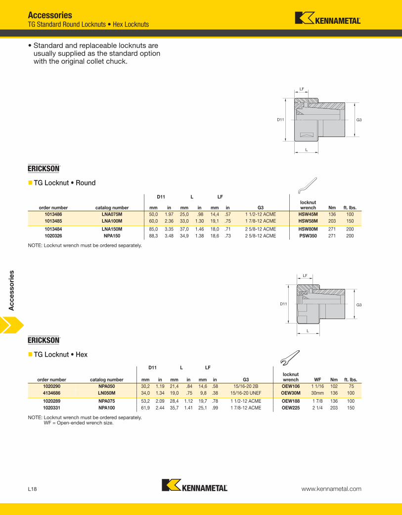
AccessoriesTG Standard Round Locknuts • Hex Locknuts
• Standard and replaceable locknuts are usually supplied as the standard option with the original collet chuck.
NOTE: Locknut wrench must be ordered separately.
NOTE: Locknut wrench must be ordered separately.WF = Open-ended wrench size.
order number catalog number mm in mm in mm in G3locknutwrench Nm ft. lbs.
1013486 LNA075M 50,0 1.97 25,0 .98 14,4 .57 1 1/2-12 ACME HSW45M 136 100
1013485 LNA100M 60,0 2.36 33,0 1.30 19,1 .75 1 7/8-12 ACME HSW58M 203 150
1013484 LNA150M 85,0 3.35 37,0 1.46 18,0 .71 2 5/8-12 ACME HSW80M 271 200
1020326 NPA150 88,3 3.48 34,9 1.38 18,6 .73 2 5/8-12 ACME PSW350 271 200
D11 L LF
D11 L LF
order number catalog number mm in mm in mm in G3locknutwrench WF Nm ft. lbs.
1020290 NPA050 30,2 1.19 21,4 .84 14,6 .58 15/16-20 2B OEW106 1 1/16 102 75
4134686 LN050M 34,0 1.34 19,0 .75 9,8 .38 15/16-20 UNEF OEW30M 30mm 136 100
1020289 NPA075 53,2 2.09 28,4 1.12 19,7 .78 1 1/2-12 ACME OEW188 1 7/8 136 100
1020331 NPA100 61,9 2.44 35,7 1.41 25,1 .99 1 7/8-12 ACME OEW225 2 1/4 203 150
� TG Locknut • Round
� TG Locknut • Hex
Ac
ce
sso
rie
s
KEN_TOOLINGSYSTEMS11_L018_L019.qxp:WIDIA 11:42 AM Page L18

� ER Locknut • Slim
L19www.kennametal.com
D11 L LF
order number catalog numbercolletseries mm in mm in mm in G3
locknutwrench
wrenchsize Nm ft. lbs.
2978768 LNECSER32M ER32 35,9 1.41 14,4 .57 8 .32 M40 x 1.5 OEW32M 32 136 100
2978769 LNECSER40M ER40 46,0 1.81 16,0 .63 8 .32 M50 x 1.5 OEW168 1 11/16 176 130
AccessoriesER Standard Short Locknuts • Slim Locknuts
• Standard and replaceable locknuts are supplied as the standard option with the original short-style collet chuck.
� ER Locknut • Short
NOTE: Locknut wrench must be ordered separately.
NOTE: Locknut wrench must be ordered separately.
D11 L LF
order number catalog numbercolletseries mm in mm in mm in G3
locknutwrench
counterbore collettorque (Nm)
straight collettorque (Nm)
counterbore collettorque
(in. lbs.)
straight collettorque
(in. lbs.)
1024642 LER08M ER08 12 .47 10,8 .43 6,1 .24 M10 X .75 ER08WEM 5 5 42 42
1024643 LER11M ER11 16 .63 12,0 .47 7,5 .30 M13 X .75 ER11WEM 12 16 106 142
1016342 LER16M ER16 22 .87 18,4 .72 11,5 .45 M19 X 1 ER16WEM 24 24 212 212
1799219 LER20M ER20 28 1.10 19,0 .75 11,5 .45 M24 X 1 ER20WEM 28 28 248 248
Ac
ce
sso
rie
s
KEN_TOOLINGSYSTEMS11_L018_L019.qxp:WIDIA 11:43 AM Page L19

L20 www.kennametal.com
D11 L LNC LF
order number catalog numbercolletseries mm in mm in mm in mm in G3
locknutwrench Nm in. lbs.
2255307 LABER16M ER16 22 .87 22 .87 4,5 .18 11,5 .45 M19 X 1 ER16WEM 24 212
2398953 LABER20M ER20 28 1.10 24 .94 5,0 .20 13,0 .51 M24 X 1 ER20WEM 28 248
AccessoriesER Slim Coolant Locknuts • Hex Locknuts
• Interchangeable with slim locknuts.
• Must be ordered separately.
• Used in conjunction with ER coolant-sealing disks for high-pressure coolant applications up to 150 bar (2,000 psi). Must be ordered separately; see page L23.
� ER Locknut • Slim Coolant
NOTE: Locknut wrench must be ordered separately.
G3
• Standard and replaceable locknuts are usuallysupplied as the standard option with the originalcollet chuck.
NOTE: Locknut wrench must be ordered separately.
order number catalog number
colletseries mm in mm in mm in G3
locknutwrench
wrench size Nm ft. lbs.
counterbore collettorque (Nm)
straight collettorque (Nm)
counterbore collettorque (ft. lbs.)
straight collettorque (ft. lbs.)
3062811 LNHSER16M ER16 28,0 1.10 17,5 .69 10,5 .41 M22 X 1.5 OEW25M 25mm 56 42 40 56 30 42
3062812 LNHSER20M ER20 34,0 1.34 19,0 .75 11,5 .45 M25 X 1.5 OEW30M 30mm 80 59 32 80 24 59
� ER Locknut • Hex
D11 L LF
Ac
ce
sso
rie
s
KEN_TOOLINGSYSTEMS11_L020_L021.qxp:WIDIA 11:43 AM Page L20

L21www.kennametal.com
AccessoriesER Coolant Hex Locknuts • Standard Round Locknuts
• Interchangeable with standard locknuts.
• Must be ordered separately.
• Used in conjunction with ER coolant-sealing disks for high-pressure coolant applications up to 150 bar (2,000 psi). Must be ordered separately; see page L23.
NOTE: Locknut wrench must be ordered separately.
order number catalog numbercolletseries mm in mm in mm in G3
locknutwrench Nm ft. lbs.
3063113 LNSER25M ER25 42 1.65 20 .79 12 .47 M32 X 1.5 ER25WM 104 77
3063114 LNSER32M ER32 50 1.97 23 .89 13 .51 M40 X 1.5 ER32WM 136 100
3063115 LNSER40M ER40 63 2.48 26 1.00 15 .59 M50 X 1.5 ER40WM 176 130
• Standard and replaceable locknuts are usually supplied as the standard option with the original collet chuck.
NOTE: Locknut wrench must be ordered separately.
D11 L LNC LF
order number catalog numbercolletseries mm in mm in mm in mm in G3
locknutwrench
wrenchsize
counterbore collettorque (Nm)
straight collettorque (Nm)
counterbore collettorque (ft. lbs.)
straight collettorque (ft. lbs.)
1854738 LNHABER16M ER16 28,0 1.10 22,5 .89 5,0 .20 15,5 .61 M22 X 1.5 OEW25M 25mm 40 56 30 42
1859410 LNHABER20M ER20 34,0 1.34 24,0 .94 5,0 .20 16,5 .65 M25 X 1.5 OEW30M 30mm 32 80 24 59
D11 L LF
� ER Locknut Hex • Coolant
� ER Locknut • Round
Ac
ce
sso
rie
s
KEN_TOOLINGSYSTEMS11_L020_L021.qxp:WIDIA 11:43 AM Page L21
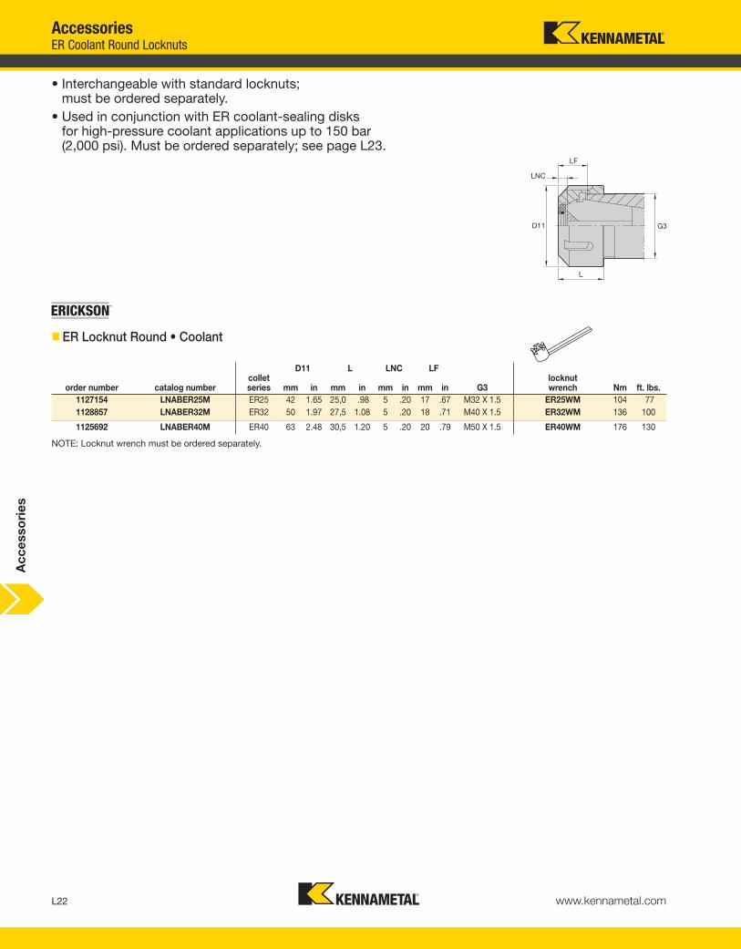
L22 www.kennametal.com
order number catalog numbercolletseries mm in mm in mm in mm in G3
locknutwrench Nm ft. lbs.
1127154 LNABER25M ER25 42 1.65 25,0 .98 5 .20 17 .67 M32 X 1.5 ER25WM 104 77
1128857 LNABER32M ER32 50 1.97 27,5 1.08 5 .20 18 .71 M40 X 1.5 ER32WM 136 100
1125692 LNABER40M ER40 63 2.48 30,5 1.20 5 .20 20 .79 M50 X 1.5 ER40WM 176 130
AccessoriesER Coolant Round Locknuts
• Interchangeable with standard locknuts;must be ordered separately.
• Used in conjunction with ER coolant-sealing disks for high-pressure coolant applications up to 150 bar(2,000 psi). Must be ordered separately; see page L23.
� ER Locknut Round • Coolant
NOTE: Locknut wrench must be ordered separately.
D11 L LNC LF
Ac
ce
sso
rie
s
KEN_TOOLINGSYSTEMS11_L022_L023.qxp:WIDIA 11:43 AM Page L22

L23www.kennametal.com
order number catalog numbercolletseries
rangemetric
rangeinch
rangefraction
1128244 CDER16035M ER16 3,0–3,5 .1181–.1387 1/8
1122128 CDER16040M ER16 3,5–4,0 .1378–.1575 5/32
1125973 CDER16045M ER16 4,0–4,5 .1575–.1772 —
1125741 CDER16050M ER16 4,5–5,0 .1772–.1969 3/16
1260100 CDER16055M ER16 5,0–5,5 .1969–.2165 7/32
1130781 CDER16060M ER16 5,5–6,0 .2165–.2362 —
1260101 CDER16065M ER16 6,0–6,5 .2362 -.2559 1/4
1260102 CDER16070M ER16 6,5–7,0 .2559–.2756 —
1260103 CDER16075M ER16 7,0–7,5 .2756–.2953 9/32
1124948 CDER16080M ER16 7,5–8,0 .3150–.3347 5/16
1254499 CDER16085M ER16 8,0–8,5 .3150–.3347 —
1120977 CDER16090M ER16 8,5–9,0 .3347–.3543 11/32
1260104 CDER16095M ER16 9,0–9,5 .3543–.3740 3/8
1128201 CDER16100M ER16 9,5–10,0 .3740–.3937 —
AccessoriesER16 Coolant Locknut Sealing Disks • Disk Sets
• 0,5mm (.020") range of sealing per disk.
• High-pressure coolant up to 150 bar (2,000 psi).
• Accommodates both metric- and inch-sized cutting tool shanks.
• Standard-sized replaceable O-rings.
� ER16 Locknut Coolant Seal Disk
order number catalog numbercolletseries quantity
dimensionalrange
incrementaldivision
1148501 CDER16000M ER16 14 3,5mm–10mm .5mm
• An economical way to purchase a group of coolant disks.
� ER16 Locknut Coolant Seal Disk Set
NOTE: ER coolant disk sets come complete with wooden protective tray.
Ac
ce
sso
rie
s
KEN_TOOLINGSYSTEMS11_L022_L023.qxp:WIDIA 11:43 AM Page L23

L24 www.kennametal.com
(.63)Ø 16,0
order number catalog numbercolletseries
rangemetric
rangeinch
rangefraction
1882862 CDER20030M ER20 2,5–3,0 .0984–.1181 —
2046541 CDER20035M ER20 3,0–3,5 .1181–.1387 1/8
2046542 CDER20040M ER20 3,5–4,0 .1378–.1575 5/32
1785844 CDER20045M ER20 4,0–4,5 .1575–.1772 —
2046613 CDER20050M ER20 4,5–5,0 .1772–.1969 3/16
2046614 CDER20055M ER20 5,0–5,5 .1969–.2165 7/32
1600448 CDER20060M ER20 5,5–6,0 .2165–.2362 —
2046615 CDER20065M ER20 6,0–6,5 .2362 -.2559 1/4
1821042 CDER20070M ER20 6,5–7,0 .2559–.2756 —
2046616 CDER20075M ER20 7,0–7,5 .2756–.2953 9/32
1568338 CDER20080M ER20 7,5–8,0 .3150–.3347 5/16
2046617 CDER20085M ER20 8,0–8,5 .3150–.3347 —
1567466 CDER20090M ER20 8,5–9,0 .3347–.3543 11/32
2046618 CDER20095M ER20 9,0–9,5 .3543–.3740 3/8
1747032 CDER20100M ER20 9,5–10,0 .3740–.3937 —
2046619 CDER20105M ER20 10,0–10,5 .3937–.4134 13/32
1923780 CDER20110M ER20 10,5–11,0 .4314–.4330 —
2046620 CDER20115M ER20 11,0–11,5 .4330–.4528 7/16
1883015 CDER20120M ER20 11,5–12,0 .4528–.4724 15/32
2046621 CDER20125M ER20 12,0–12,5 .4724–.4921 —
2046622 CDER20130M ER20 12,5–13,0 .4921–.5118 1/2
AccessoriesER20 Coolant Locknut Sealing Disks • Disk Sets
• 0,5mm (.020") range of sealing per disk.
• High-pressure coolant up to 150 bar (2,000 psi).
• Accommodates both metric- and inch-sized cutting tool shanks.
• Standard-sized, replaceable O-rings.
� ER20 Locknut Coolant Seal Disk
order number catalog numbercolletseries quantity
dimensionalrange
incrementaldivision
1720848 CDER20000M ER20 20 3,5mm–13mm .5mm
• An economical way to purchase a group of coolant disks.
� ER20 Locknut Coolant Seal Disk Set
NOTE: ER coolant disk sets come complete with wooden protective tray.
Ac
ce
sso
rie
s
KEN_TOOLINGSYSTEMS11_L024_L025.qxp:WIDIA 11:43 AM Page L24

L25www.kennametal.com
order number catalog numbercolletseries
rangemetric
rangeinch
rangefraction
1820323 CDER25035M ER25 3,0 - 3,5 .1181 - .1387 1/8
1136043 CDER25040M ER25 3,5 - 4,0 .1378 - .1575 5/32
1260105 CDER25045M ER25 4,0 - 4,5 .1575 - .1772 —
1130194 CDER25050M ER25 4,5 - 5,0 .1772 - .1969 3/16
1260106 CDER25055M ER25 5,0 - 5,5 .1969 - .2165 7/32
1127146 CDER25060M ER25 5,5 - 6,0 .2165 - .2362 —
1260107 CDER25065M ER25 6,0 - 6,5 .2263 -.2559 1/4
1126670 CDER25070M ER25 6,5 - 7,0 .2559 - .2756 —
1260108 CDER25075M ER25 7,0 - 7,5 .2756 - .2953 9/32
1126607 CDER25085M ER25 8,0 - 8,5 .3150 - .3347 —
1126599 CDER25080M ER25 7,5 - 8,0 .3150 - .3347 —
1129478 CDER25090M ER25 8,5 - 9,0 .3347 - .3543 11/32
1260109 CDER25095M ER25 9,0 - 9,5 .3543 - .3740 3/8
1126613 CDER25100M ER25 9,5 - 10,0 .3740 - .3937 —
1124966 CDER25105M ER25 10,0 - 10,5 .3937 - .4134 13/32
1126677 CDER25110M ER25 10,5 - 11,0 .4134 - .4330 —
1260110 CDER25115M ER25 11,0 - 11,5 .4330 - .4528 7/16
1125474 CDER25120M ER25 11,5 - 12,0 .4528 - .4724 15/32
1260111 CDER25125M ER25 12,0 - 12,5 .4724 - .4921 —
1129141 CDER25130M ER25 12,5 - 13,0 .4921 - .5118 1/2
1260112 CDER25135M ER25 13,0 - 13,5 .5118 - .5315 17/32
1125481 CDER25140M ER25 13,5 - 14,0 .5315 - .5512 —
1260113 CDER25145M ER25 14,0 - 14,5 .5512 - .5709 9/16
1260114 CDER25150M ER25 14,5 - 15,0 .5709 - .5906 37/64
1260115 CDER25155M ER25 15,0 - 15,5 .5906 - .6102 19/32
1128486 CDER25160M ER25 15,5 - 16,0 .6102 - .6300 5/8
AccessoriesER25 Coolant Locknut Sealing Disks • Disk Sets
• 0,5mm (.020") range of sealing per disk.
• High-pressure coolant up to 150 bar (2,000 psi).
• Accommodates both metric- and inch-sized cutting tool shanks.
• Standard-sized, replaceable O-rings.
� ER25 Locknut Coolant Seal Disk
order number catalog numbercolletseries quantity
dimensionalrange
incrementaldivision
1254501 CDER25000M ER25 26 3,5mm–16mm .5mm
• An economical way to purchase a group of coolant disks.
� ER25 Locknut Coolant Seal Disk Set
NOTE: ER coolant disk sets come complete with wooden protective tray.
Ac
ce
sso
rie
s
KEN_TOOLINGSYSTEMS11_L024_L025.qxp:WIDIA 11:43 AM Page L25
L26 www.kennametal.com
order number catalog numbercolletseries
rangemetric
rangeinch
rangefraction
1120969 CDER32035M ER32 3,0–3,5 .1181–.1387 1/8
1125347 CDER32040M ER32 3,5–4,0 .1378–.1575 5/32
1260116 CDER32045M ER32 4,0–4,5 .1575–.1772 —
1148555 CDER32050M ER32 4,5–5,0 .1772–.1969 3/16
1260117 CDER32055M ER32 5,0–5,5 .1969–.2165 7/32
1121104 CDER32060M ER32 5,5–6,0 .2165–.2362 —
1120661 CDER32065M ER32 6,0–6,5 .2362 -.2559 1/4
1131561 CDER32070M ER32 6,5–7,0 .2559–.2756 —
1260118 CDER32075M ER32 7,0–7,5 .2756–.2953 9/32
1132831 CDER32080M ER32 7,5–8,0 .3150–.3347 5/16
1260119 CDER32085M ER32 8,0–8,5 .3150–.3347 —
1122258 CDER32090M ER32 8,5–9,0 .3347–.3543 11/32
1260120 CDER32095M ER32 9,0–9,5 .3543–.3740 3/8
1136052 CDER32100M ER32 9,5–10,0 .3740–.3937 —
1260121 CDER32105M ER32 10,0–10,5 .3937–.4134 13/32
1135241 CDER32110M ER32 10,5–11,0 .4134–.4330 —
1260122 CDER32115M ER32 11,0–11,5 .4330–.4528 7/16
1128840 CDER32120M ER32 11,5–12,0 .4528–.4724 15/32
1125490 CDER32125M ER32 12,0–12,5 .4724–4921 —
1126728 CDER32130M ER32 12,5–13,0 .4921–.5118 1/2
1260123 CDER32135M ER32 13,0–13,5 .5118–.5315 17/32
1132848 CDER32140M ER32 13,5–14,0 .5315–.5512 —
1127692 CDER32145M ER32 14,0–14,5 .5512–.5709 9/16
1232472 CDER32150M ER32 14,5–15,0 .5709–.5905 —
1260124 CDER32155M ER32 15,0–15,5 .5905–.6102 19/32
1125023 CDER32160M ER32 15,5–16,0 .6102–.6300 5/8
1260125 CDER32165M ER32 16,0–16,5 .6300–.6496 —
1260126 CDER32170M ER32 16,5–17,0 .6496–.6693 21/32
1260127 CDER32175M ER32 17,0–17,5 .6693–.6890 11/16
1126732 CDER32180M ER32 17,5–18,0 .6890–.7087 —
1260128 CDER32185M ER32 18,0–18,5 .7087–.7284 23/32
1155337 CDER32190M ER32 18,5–19,0 .7284–.7480 3/4
1260129 CDER32195M ER32 19,0–19,5 .7480–.7677 —
1124951 CDER32200M ER32 19,5–20,0 .7677–.7874 25/32
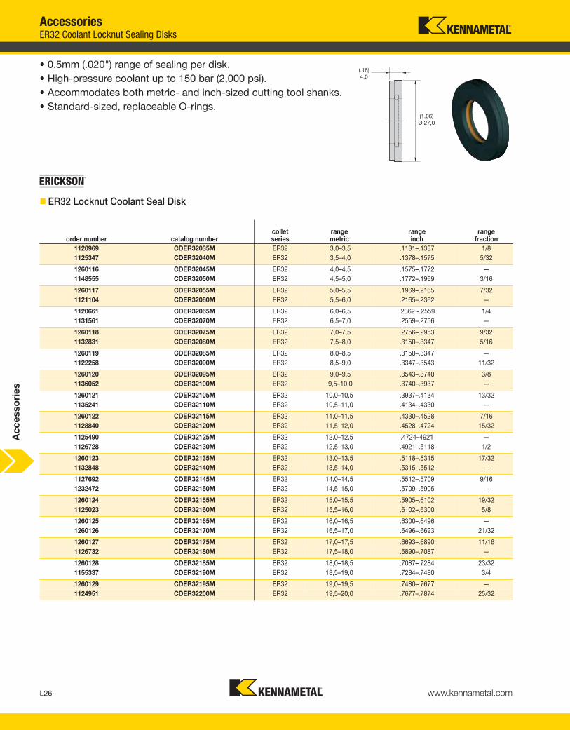
AccessoriesER32 Coolant Locknut Sealing Disks
� ER32 Locknut Coolant Seal Disk
• 0,5mm (.020") range of sealing per disk.
• High-pressure coolant up to 150 bar (2,000 psi).
• Accommodates both metric- and inch-sized cutting tool shanks.
• Standard-sized, replaceable O-rings.
Ac
ce
sso
rie
s
KEN_TOOLINGSYSTEMS11_L026_L027.qxp:WIDIA 11:43 AM Page L26

L27www.kennametal.com
order number catalog numbercolletseries quantity
dimensionalrange
incrementaldivision
1123496 CDER32000M ER32 34 3,5mm–20mm .5mm
Accessories
• An economical way to purchase a group of coolant disks.
� ER32 Locknut Coolant Seal Disk Set
NOTE: ER coolant disk sets come complete with wooden protective tray.
ER32 Coolant Locknut Sealing Disk Sets
Ac
ce
sso
rie
s
KEN_TOOLINGSYSTEMS11_L026_L027.qxp:WIDIA 11:43 AM Page L27

L28 www.kennametal.com
order number catalog numbercolletseries
rangemetric
rangeinch
rangefraction
1260131 CDER40035M ER40 3,0–3,5 .1181–.1387 1/8
1260132 CDER40040M ER40 3,5–4,0 .1378–.1575 5/32
1260133 CDER40045M ER40 4,0–4,5 .1575–.1772 —
1260134 CDER40050M ER40 4,5–5,0 .1772–.1969 3/16
1260135 CDER40055M ER40 5,0–5,5 .1969–.2165 7/32
1128810 CDER40060M ER40 5,5–6,0 .2165–.2362 —
1260136 CDER40065M ER40 6,0–6,5 .2362 -.2559 1/4
1128828 CDER40070M ER40 6,5–7,0 .2559–.2756 —
1260137 CDER40075M ER40 7,0–7,5 .2756–.2953 9/32
1126684 CDER40080M ER40 7,5–8,0 .3150–.3347 5/16
1260138 CDER40085M ER40 8,0–8,5 .3150–.3347 —
1129486 CDER40090M ER40 8,5–9,0 .3347–.3543 11/32
1260139 CDER40095M ER40 9,0–9,5 .3543–.3740 3/8
1128834 CDER40100M ER40 9,5–10,0 .3740–.3937 —
1260140 CDER40105M ER40 10,0–10,5 .3937–.4134 13/32
1125622 CDER40110M ER40 10,5–11,0 .4134–.4330 —
1260141 CDER40115M ER40 11,0–11,5 .4330–.4528 7/16
1125678 CDER40120M ER40 11,5–12,0 .4528–.2724 15/32
1260142 CDER40125M ER40 12,0–12,5 .4724–.4921 —
1260143 CDER40130M ER40 12,5–13,0 .4921–.5118 1/2
1260144 CDER40135M ER40 13,0–13,5 .5118–.5315 17/32
1128841 CDER40140M ER40 13,5–14,0 .5315–.5512 —
1260145 CDER40145M ER40 14,0–14,5 .5512–.5709 9/16
1128848 CDER40150M ER40 14,5–15,0 .5709–.5905 —
1260146 CDER40155M ER40 15,0–15,5 .5905–.6102 19/32
1125686 CDER40160M ER40 15,5–16,0 .6102–.6300 5/8
1260147 CDER40165M ER40 16,0–16,5 .6300–.6496 —
1125623 CDER40170M ER40 16,5–17,0 .6496–.6693 21/32
AccessoriesER40 Coolant Locknut Sealing Disks
• 0,5mm (.020") range of sealing per disk.
• High-pressure coolant up to 150 bar (2,000 psi).
• Accommodates both metric- and inch-sized cutting tool shanks.
• Standard-sized, replaceable O-rings.
� ER40 Locknut Coolant Seal Disk
(continued)
Ac
ce
sso
rie
s
KEN_TOOLINGSYSTEMS11_L028_L029.qxp:WIDIA 11:43 AM Page L28
L29www.kennametal.com
1260148 CDER40175M ER40 17,0–17,5 .6693–.6890 11/16
1128856 CDER40180M ER40 17,5–18,0 .6890–.7087 —
1260149 CDER40185M ER40 18,0–18,5 .7087–.7248 23/32
1260150 CDER40190M ER40 18,5–19,0 .7284–.7480 3/4
1260151 CDER40195M ER40 19,0–19,5 .7480–.7677 —
1128845 CDER40200M ER40 19,5–20,0 .7677–.7874 25/32
1260152 CDER40205M ER40 20,0–20,5 .7874–.8071 —
1260153 CDER40215M ER40 21,0–21,5 .7874–.8465 27/32
1129413 CDER40210M ER40 20,5–21,0 .8071–.8268 13/16
1121616 CDER40220M ER40 21,5–22,0 .8465–.8661 —
1254500 CDER40230M ER40 22,5–23,0 .8858–.9055 29/32
1260154 CDER40225M ER40 23,0–23,5 .9055–.9252 —
1260155 CDER40235M ER40 23,0–23,5 .9055–.9252 —
1260156 CDER40240M ER40 23,5–24,0 .9252–.9449 15/16
1260157 CDER40245M ER40 24,0–24,5 .9449–.9646 —
1128850 CDER40250M ER40 24,5–25,0 .9646–.9843 31/32
1971143 CDER40255M ER40 25,0–25,5 .9843–.1.0039 1
1124539 CDER40260M ER40 25,5–26,0 1.0039–1.0236 —
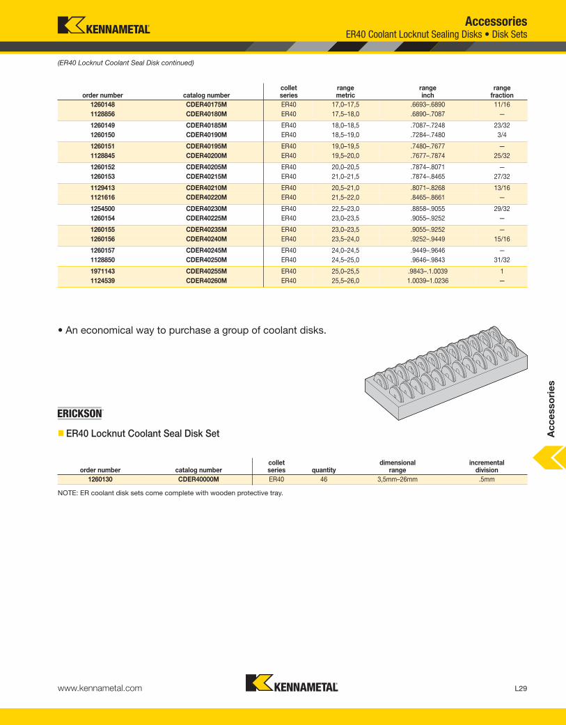
(ER40 Locknut Coolant Seal Disk continued)
order number catalog numbercolletseries quantity
dimensionalrange
incrementaldivision
1260130 CDER40000M ER40 46 3,5mm–26mm .5mm
• An economical way to purchase a group of coolant disks.
� ER40 Locknut Coolant Seal Disk Set
NOTE: ER coolant disk sets come complete with wooden protective tray.
order number catalog numbercolletseries
rangemetric
rangeinch
rangefraction
AccessoriesER40 Coolant Locknut Sealing Disks • Disk Sets
Ac
ce
sso
rie
s
KEN_TOOLINGSYSTEMS11_L028_L029.qxp:WIDIA 11:43 AM Page L29

L30 www.kennametal.com
AccessoriesDA 01 Double Angle Locknuts
collet series nose piecelocknut
� DA01 Locknut Hex
NOTE: Locknut and nose piece need to be ordered separately.Locknut wrench to be ordered separately.
� DA01 Nose Piece
NOTE: Locknut and nose piece need to be ordered separately.
order number catalog numbercolletseries D11 WF G3
1021948 LN101 DA100 1.73 1.50 1.375-12 UNF
1021950 LN181 DA180 2.02 1.75 1.625-12 UN
1022884 LN201 DA200 1.44 1.25 1.125-16 UN
1022886 LN301 DA300 .86 .75 .625-18 UNF
Ac
ce
sso
rie
s
order number catalog numbercolletseries D2 LF
1021918 NP101 DA100 1.06 .51
1022702 NP181 DA180 1.33 .35
1021920 NP201 DA200 .81 .37
1022726 NP301 DA300 .51 .35
KEN_TOOLINGSYSTEMS11_L030_L031.qxp:WIDIA 11:43 AM Page L30

L31www.kennametal.com
Accessories
� DA04 Double Angle Locknuts
order number catalog numbercolletseries D11 L LF WF G3
1013469 LNA104M DA100 1.06 1.51 .62 .94 .9375-20 UNEF
1013470 LNA184M DA180 1.44 1.60 .49 1.18 1.250-16 UN
1013489 LNAL04M L 1.50 1.28 .40 1.25 1.313-16 UN
1013488 LNAK04M K 1.06 1.19 .37 .94 .9375-20 UNEF
1013472 LNA304M DA300 .56 1.13 .48 .50 .4375-32 UN
1013471 LNA204M DA200 .85 1.42 .47 .75 .6875-20 UN
1013440 LN000M DA000 .40 .89 .18 .35 M9 X .9
NOTE: Locknut needs to be ordered separately.
� DA08 Double Angle Locknuts
NOTE: Locknut needs to be ordered separately.
DA 04 and DA 08 Double Angle Locknuts
order number catalog numbercolletseries D11 D2 L LF WF G3
1013467 LNA108M DA100 1.44 1.24 .91 .58 1.25 1.000-14 UNS
1013439 LNA208M DA200 1.08 .93 .75 .48 .94 .750-16 UNF
1013468 LNA308M DA300 .77 .66 .73 .43 .67 .5625-18 UNF
Ac
ce
sso
rie
s
collet series
collet series
KEN_TOOLINGSYSTEMS11_L030_L031.qxp:WIDIA 11:44 AM Page L31

L32 www.kennametal.com
L
order number catalog number mm inWSWS
wrench sizeWSMS
wrench size G3X
1019943 SS031031G 7,9 .31 4mm & 5/32 — 5/16-24UNF LH
1019975 SS038031G 7,9 .31 4mm & 5/32 — 3/8-24UNF LH
1019977 SS044038G 9,5 .38 4mm & 5/32 — 7/16-20UNF LH
1019979 SS050038G 9,5 .38 4mm & 5/32 — 1/2-20UNF LH
1019981 SS056041G 9,5 .38 4mm & 5/32 — 9/16-18UNF LH
1019983 SS062041G 9,5 .38 4mm & 5/32 — 5/8-18UNF LH
1019985 SS075041G 10,3 .41 4mm & 5/32 — 3/4-16UNF LH
1019987 SS081041G 10,3 .41 4mm & 5/32 8mm & 5/16 13/16-16UN LH
1019989 SS094041G 10,3 .41 4mm & 5/32 8mm & 5/16 15/16-16UN LH
1019991 SS112041G 10,3 .41 4mm & 5/32 8mm & 5/16 1 1/8-16UN LH
1020023 SS125050G 12,7 .50 4mm & 5/32 8mm & 5/16 1 1/4-12UNF LH
1020017 SS162062G 15,8 .62 4mm & 5/32 8mm & 5/16 1 5/8-12UN LH
1020049 SS175062G 15,8 .62 4mm & 5/32 8mm & 5/16 1 3/4-12UN LH
AccessoriesStop Screws
• Replacement stop screws.
• Coolant, blank, and extended caps are available for added capabilities.
� Stop Screw
Ac
ce
sso
rie
s
KEN_TOOLINGSYSTEMS11_L032_L033.qxp:WIDIA 11:44 AM Page L32

Experience the advantages at your Authorized Kennametal Distributor or at www.kennametal.com.
www.kennametal.com
The TunableTooling
• Proprietary features provide superior surface finish and increased productivity.
• Wide product offering — from boring bars, extensions, and holders to rotating
adapters and modular sections.
• Reduce setup time with KM™ Quick Change Tooling — now an ISO Standard!
• Customize Kennametal’s pre-tuned boring bars — after they’re on the machine —
to optimize performance in your specific machining operations.
For tighter tolerances, reduced scrap rates, and improved tool life, you can rely on Kennametal Tunable Tooling!
Internal dampening package eliminates chatter, vibration,
and harmonics in all your deep-hole boring applications!
KEN_TOOLINGSYSTEMS11_L032_L033.qxp:WIDIA 11:44 AM Page L33

L34 www.kennametal.com
D2 LF
order number catalog number mm in mm instop screwreference
1021134 SSCC031 6,5 .25 2,4 .09 SS031031G
1021138 SSCC044 9,5 .37 3,0 .12 SS044038G
1021140 SSCC050 11,0 .43 3,0 .12 SS050038G
1021142 SSCC056 12,0 .47 4,0 .16 SS056041G
1092046 SSCC062 14,0 .55 4,5 .18 SS062041G
1021154 SSCC075 17,0 .67 6,0 .24 SS075041G
1021156 SSCC081 17,0 .67 6,0 .24 SS081041G
1021158 SSCC094 21,8 .86 8,5 .33 SS094041G
1021160 SSCC112 24,5 .97 9,8 .38 SS112041G
1021162 SSCC125 29,0 1.14 12,0 .47 SS125050G
1021176 SSCC162 37,0 1.46 15,5 .61 SS162062G
1021178 SSCC175 42,0 1.65 18,5 .73 SS175062G
D2 LF
order number catalog number mm in mm instop screwreference
1021180 SSC031 6,5 .26 2,2 .09 SS031031G
1021204 SSC044 9,5 .37 2,2 .09 SS044038G,SS0500384
1021206 SSC056 12,0 .47 2,2 .09 SS075041G,SS056041G,SS062041G
1021208 SSC081 17,0 .67 2,2 .09 SS081041G,SS094041G
AccessoriesCoolant Caps • Blank Caps
• Stop screw caps can easily be snapped onto their respective stop screws, referenced in the first column in respective tables below, for added capabilities.
� Coolant Cap
NOTE: For use with through-coolant applications for improved sealing.
� Blank Cap
NOTE: A solid cap for small-diameter cutting tools with no through-coolant capability.
Ac
ce
sso
rie
s
KEN_TOOLINGSYSTEMS11_L034_L035.qxp:WIDIA 11:44 AM Page L34

L35www.kennametal.com
D D2 LF
order number catalog number mm in mm in mm instop screwreference
1021216 SSC038081 8,1 .32 8,1 .32 20,5 .81 SS038031G
1021220 SSC056066 12,0 .47 5,0 .20 16,7 .66 SS094041G,SS075041G,SS056041G
1021222 SSC081103 17,0 .67 5,0 .20 26,2 1.03 SS094041G,SS081041G
1021254 SSC112150 24,5 .96 12,0 .47 38,1 1.50 SS150062G,SS125050G,SS112041G
Accessories
• Stop screw caps can easily be snapped onto their respective stop screws, referenced in the first column in respective tables below, for added capabilities.
� Extended Cap
NOTE: For greater access and reaching inside collet cavities.
Extended Caps
Ac
ce
sso
rie
s
KEN_TOOLINGSYSTEMS11_L034_L035.qxp:WIDIA 11:44 AM Page L35

L36 www.kennametal.com
AccessoriesShell Mill Adapter Lock Screws
� SM Cap Lock Screw • Metric
� SM Lock Screw • Metric
order number catalog numberexternal
thread size D2 L LTHD
1147969 KLS27MPKG M12X1.75 34,8 29,9 17,5
1736199 KLS32M M16X2.0 41,8 34,9 20,5
1016374 KLS40M M20X2.5 51,8 39,9 24,0
1178775 KLS50M M24X3 62,8 47,9 28,5
(continued)
I.D. drive
size
external
thread
size
external
thread
size
order number catalog numberexternal
thread size D2 LI.D.
drive size
1905810 MS1294 M8X1.25 13,0 25,0 6mm
1129648 MS1234 M10X1.5 16,0 25,0 8mm
Ac
ce
sso
rie
s
KEN_TOOLINGSYSTEMS11_L036_L037.qxp:WIDIA 11:44 AM Page L36

L37www.kennametal.com
AccessoriesShell Mill Adapter Lock Screws
� SM Round Lock Screw • Metric
� SM Lock Screw • Inch
(SM Lock Screws continued)
order number catalog numberexternal
thread size D2 L LTHDI.D.
drive size
4078806 KLSS27M M12X1.75 35,0 30,9 22,0 10mm
4078807 KLSS32M M16X2.0 42,0 37,9 26,0 14mm
4078808 KLSS40M M20X2.5 52,0 44,9 30,0 17mm
order number catalog numberexternal
thread size D2 L LTHDI.D.
drive size
1020548 KLS05 .250-28 UNF .656 1.000 .656 3/16
1020550 KLS07 .375 - 24 UNF .875 1.062 .687 1/4
1020552 KLS10 .500 - 20 UNF 1.188 1.187 .812 5/16
1020574 KLS12 .625 - 18 UNF 1.500 1.535 1.040 5/16
1020576 KLS15 3/4 - 16 UNF 1.875 1.516 1.016 3/8
1020578 KLS20 1.000 - 14 UNS — — — 9/16
I.D. drive
size
external
thread
size
I.D. drive
size
external
thread
size
Ac
ce
sso
rie
s
KEN_TOOLINGSYSTEMS11_L036_L037.qxp:WIDIA 11:44 AM Page L37

L38 www.kennametal.com
AccessoriesShell Mill Coolant Lock Screws • Tightening Fixtures, KM™ Vise Mounts
• Coolant lock screw to convert a standard shell milladapter into a through-coolant version.
� SM Lock Screw Coolant • Inch
• Vise mount pot to hold KM toolholders for tightening/locking operations.
� TF • KM Vise Mount
order number catalog numberexternal
thread size D2 L LTHDI.D.
drive size
1151259 KLSSH10 .500-20 UNF 1.2 1.2 .8 5/16
1151260 KLSSH12 .625-18 UNF 1.5 1.5 1.0 5/16
1151261 KLSSH15 .750-16 UNF 1.9 1.5 1.0 3/8
1151262 KLSSH20 1.000-14 UNS 2.5 1.5 1.0 9/16
1151315 KLSSH25 1.000-14 UNS 3.1 2.0 1.5 9/16
D2 L LS WF
order number catalog numbersystem
size mm in mm in mm in mm in
1021816 KM40TF KM40 50,80 2.00 152,4 6.00 101,6 4.00 44,45 1.750
1021817 KM50TF KM50 63,50 2.50 152,4 6.00 101,6 4.00 57,15 2.250
1021818 KM63TF KM63 76,20 3.00 152,4 6.00 101,6 4.00 69,15 2.750
2606542 KM80TF KM80 88,90 3.50 152,4 6.00 101,6 4.00 85,73 3.375
I.D. drive
size
external
thread
size
Ac
ce
sso
rie
s
KEN_TOOLINGSYSTEMS11_L038_L039.qxp:WIDIA 11:44 AM Page L38

L39www.kennametal.com
• Vise mount pot to hold HSK toolholders for tightening/locking operations.
� TF • KM4X and HSK Vise Mount
order number catalog number mm in mm in mm in mm inwrench size clamp screw
1013573 TFHSK32A 32,0 1.26 50,8 2.00 63,5 2.50 82,5 3.25 3mm & 1/8
1013584 TFHSK40A 40,0 1.57 60,0 2.36 63,5 2.50 82,5 3.25 4mm & 5/32
1013586 TFHSK63A 63,0 2.48 98,4 98.41 69,9 2.75 82,5 3.25 8mm & 5/16
1013587 TFHSK80A 80,0 3.15 108,0 4.25 120,7 4.75 82,5 3.25 8mm & 5/16
1013588 TFHSK100A 100,0 3.94 135,0 5.31 139,7 5.50 82,5 3.25 8mm & 5/16
AccessoriesTightening Fixtures, KM4X™ and HSK Vise Mounts
D1 D2 L WF
Ac
ce
sso
rie
s
KEN_TOOLINGSYSTEMS11_L038_L039.qxp:WIDIA 11:44 AM Page L39
L40 www.kennametal.com
AccessoriesTightening Fixtures, HSK Universal Mounts and Sleeves
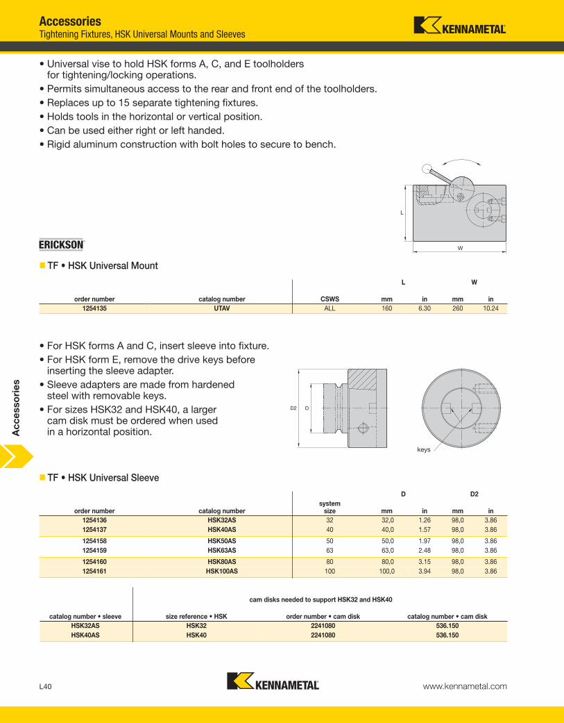
• Universal vise to hold HSK forms A, C, and E toolholders for tightening/locking operations.
• Permits simultaneous access to the rear and front end of the toolholders.
• Replaces up to 15 separate tightening fixtures.
• Holds tools in the horizontal or vertical position.
• Can be used either right or left handed.
• Rigid aluminum construction with bolt holes to secure to bench.
• For HSK forms A and C, insert sleeve into fixture.
• For HSK form E, remove the drive keys beforeinserting the sleeve adapter.
• Sleeve adapters are made from hardened steel with removable keys.
• For sizes HSK32 and HSK40, a larger cam disk must be ordered when used in a horizontal position.
L W
order number catalog number CSWS mm in mm in
1254135 UTAV ALL 160 6.30 260 10.24
D D2
order number catalog numbersystem
size mm in mm in
1254136 HSK32AS 32 32,0 1.26 98,0 3.86
1254137 HSK40AS 40 40,0 1.57 98,0 3.86
1254158 HSK50AS 50 50,0 1.97 98,0 3.86
1254159 HSK63AS 63 63,0 2.48 98,0 3.86
1254160 HSK80AS 80 80,0 3.15 98,0 3.86
1254161 HSK100AS 100 100,0 3.94 98,0 3.86
cam disks needed to support HSK32 and HSK40
catalog number • sleeve size reference • HSK order number • cam disk catalog number • cam disk
HSK32AS HSK32 2241080 536.150
HSK40AS HSK40 2241080 536.150
� TF • HSK Universal Mount
� TF • HSK Universal Sleeve
keys
Ac
ce
sso
rie
s
KEN_TOOLINGSYSTEMS11_L040_L041.qxp:WIDIA 11:44 AM Page L40

L41www.kennametal.com
AccessoriesTightening Fixtures, 7/24 Steep Taper Vise Mounts • Universal Mounts
• Vise mount pot to hold steep taper toolholders for tightening/locking operations.
� TF • ST Vise Mount
order number catalog numbersystem
size
1013591 UTV5030 30, 35, 40, 45, & 50
• Universal vise to hold 30, 35, 40, 45, and 50 7/24 steep taper toolholders for tightening/locking operations.
• Permits simultaneous access to the retention knob and locknut.
• Replaces up to five separate tightening fixtures.
• Holds tools in the horizontal or vertical position.
• Can be used either right or left handed.
• Holds most 7/24 tapers including ANSI, ISO, DIN, V-flange, BT, and NMTB.
• Handle position is easily changed with a simple button push.
• No setups, bushings, or spare parts required.
• 400 Nm (300 ft. lbs.) maximum torque capacity.
� TF • ST Universal Mount
D2 L WF
order number catalog numbersystem
size mm in mm in mm in
1013620 TF30 30 88,9 3.50 109,5 4.31 76,2 3.00
1013636 TF40 40 88,9 3.50 122,2 4.81 76,2 3.00
1013638 TF50 50 133,4 5.25 165,1 6.50 114,3 4.50
system size
Ac
ce
sso
rie
s
KEN_TOOLINGSYSTEMS11_L040_L041.qxp:WIDIA 11:44 AM Page L41

L42 www.kennametal.com
D2 L1
order number catalog numbersystem
size mm in mm in
1019237 KM32P KM32 32 1.26 25 .98
1144452 KM40P KM40 40 1.57 27 1.06
1144501 KM50P KM50 50 1.97 31 1.22
1019945 KM63TSP KM63TS 63 2.48 33 1.30
1144328 KM80P KM80 80 3.15 37 1.46
AccessoriesP-KM Spindle Plugs • HSK Spindle Plugs
• Prevents machine tool spindle from becomingcontaminated when not in use.
� Spindle Plug • KM™
D2 L1
order number catalog numbersystem
size mm in mm in kg
1256061 HSK63AP 63 50 1.97 42,3 1.66 0,7
1307767 HSK100AP 100 80 3.15 45,3 1.78 0,7
• Prevents machine tool spindle from becomingcontaminated when not in use.
� P-HSK • Form A
system size
system size
Ac
ce
sso
rie
s
KEN_TOOLINGSYSTEMS11_L042_L043.qxp:WIDIA 11:44 AM Page L42

L43www.kennametal.com
order number catalog numbersystem
size
1727267 KMSW32 32
1606113 KMSW40 40
1612900 KMSW50 50
1612922 KMSW63 63
1612923 KMSW80 80
AccessoriesKM™ • HSK • 7/24 Steep Taper Spindle Wipers
• Cleans taper and face of machine spindle and tool adapter.
� SW-KM
D2 LU
order number catalog numbersystem
size mm in mm in
1518662 HSK32SW 32 45 1.77 11 .43
1518630 HSK40SW 40 45 1.77 14 .55
1514497 HSK50SW 50 53 2.09 17 .67
1518677 HSK63SW 63 66 2.60 22 .87
1518681 HSK100SW 100 103 4.06 35 1.38
• Cleans taper and face of machine spindle and tool adapter.
� SW-HSK
order number catalog numbersystem
size
1288838 SW30 30
1288842 SW40 40
1192562 SW50 50
• Cleans taper of machine spindle and tool adapter.
� SW-ST
Ac
ce
sso
rie
s
KEN_TOOLINGSYSTEMS11_L042_L043.qxp:WIDIA 11:44 AM Page L43

L44 www.kennametal.com
AccessoriesHSK Coolant Supply Units • Wrenches
• Designed in accordance with DIN 69893.
• Withstand coolant pressure up to 80 bar (1,160 psi).
• Directs flow of coolant through the tool and avoids spindle mechanism contaminationfrom flow-back.
• Standard-sized replaceable O-rings.
• Designed to lock and unlock theHSK coolant supply units.
� HSK Wrench
� HSK Coolant Supply Unit • Assembly
Ac
ce
sso
rie
s
D2 L
order number catalog number CSWS mm in mm in Nm ft. lbs.
1176487 170.195 40A & 40E 13,0 .51 120 4.72 10 7
1132992 170.196 50A & 50E & 63F 14,5 .57 114 4.49 15 11
1134161 170.197 63A & 63T & 80F 16,5 .65 122 4.80 20 14
1127524 170.198 80A 19,0 .75 130 5.12 25 18
1132993 170.199 100A 22,0 .87 141 5.55 30 22
D5 L LTHD
order number catalog numbersystem
size mm in mm in mm in GX Nm ft. lbs.
1132083 193.158 40A & 40E 8,0 .3 29,5 1.2 7,5 .30 M12 X 1 10 7
1132144 193.159 50A & 50E & 63F 10,0 .4 32,7 1.3 9,5 .37 M16 X 1 15 11
1132145 193.160 63A & 63T & 80F 12,0 .5 36,2 1.4 11,5 .45 M18 X 1 20 14
1132146 193.161 80A 14,0 .6 40,2 1.6 13,5 .53 M20 X 1.5 25 18
1132147 193.162 100A 16,0 .6 43,6 1.7 15,5 .61 M24 X 1.5 30 22
KEN_TOOLINGSYSTEMS11_L044_L045.qxp:WIDIA 11:44 AM Page L44

L45www.kennametal.com
Retention Knobs
WARNING
taper size suggested torque max (ft. lbs.) suggested torque max (Nm)
30 40 54
40 85 115
50 110 149
machine builder machine builder’s drawing and/or numbers machine model number
taper size G thread A angle
D1 D2 D3 D4 D5
L L1 L2 through coolant needed? O-ring needed?
Accessories
Retention knobs are available in various styles and are not always interchangeablebecause all are machine and spindle specific. The proper retention knob must beused at all times with the appropriate adapter, according to machine specificationsas provided by the machine's original manufacturer. Failure to use the correctretention knob, or to adequately install and tighten the correct retention knob, may result in an adapter loosening. Using a combination of metric and non-metriccomponents can result in an inadequate coupling of the adapter to the spindleduring machining, causing the component to fail.
While Kennametal has endeavored to obtain accurate and up-to-date informationregarding retention knob selection based on individual machine tool builderspecifications, we cannot guarantee that the information and specificationscontained in this catalog are complete and that they have not been modified orsuperseded by the manufacturer. You, the machine tool operator, areultimately responsible for proper selection and use of retention knobs.The purchase of retention knobs from Kennametal is subject to Kennametal’sStandard Terms and Conditions of Sale.
Machining center manufacturers use numerous types and styles of retentionknobs. Kennametal has listed some of the most popular retention knobs in the industry on the next few pages.
If a retention knob is not shown, please contact your Kennametal Representative or call Kennametal Customer Service and have the following information available:
The machine builder should recommend the required tightening torque for the retention knobs. This information is not always available.
Kennametal has referenced a suggested maximum torque setting and offers a specialized socket just for retention knobs. Please see these socket wrench sizes listed against each knob.
Ac
ce
sso
rie
s
KEN_TOOLINGSYSTEMS11_L044_L045.qxp:WIDIA 11:45 AM Page L45

L46 www.kennametal.com
• Metric thread.
• Piloted with O-ring.
• No through coolant.
NOTE: WF = Width over flats for open-ended wrench or socket wrench.For socket wrench, see page L51.
AccessoriesRetention Knobs DIN 69872 Form A Metric • Form B Metric
• Metric thread.
• Piloted.
• Through coolant.
NOTE: WF = Width over flats for open-ended wrench or socket wrench.For socket wrench, see page L51.
order number catalog numbersystem
size GX A CHTA D5 DN DPW HDD LF LPR Lwrench socket Nm
1192424 RK40DVM 40 M16 X 2 7,05 75° 23 13,95 16,97 18,97 20,0 26,00 54 RKW40 115
1192430 RK50DVM 50 M24 X 3 11,55 75° 36 20,95 24,97 27,97 25,0 34,00 74 RKW50M 143
order number catalog numbersystem
size GX A CHTA D5 DN DPW HDD LF LPR Lwrench socket Nm
1192423 RK40DVBM 40 M16 X 2 7,05 75° 22,9 13,95 16,97 18,97 20 26 54 RKW40 115
1192429 RK50DVBM 50 M24 X 3 11,55 75° 35,9 20,95 24,97 27,97 25 34 74 RKW50M 143
� RK DIN 69872 Form A • Metric
� RK DIN 69872 Form B • MetricAc
ce
sso
rie
s
KEN_TOOLINGSYSTEMS11_L046_L047.qxp:WIDIA 11:45 AM Page L46

L47www.kennametal.com
AccessoriesRetention Knobs ISO 7388/2 Type A Metric • Type B Metric
• Metric thread.
• Piloted.
• Through coolant.
NOTE: WF = Width over flats for open-ended wrench or socket wrench.For socket wrench, see page L51.
• Metric thread.
• Piloted.
• Through coolant.
NOTE: WF = Width over flats for open-ended wrench or socket wrench.For socket wrench, see page L51.
order number catalog numbersystem
size GX A CHTA D5 DN DPW HDD LF LPR Lwrench socket Nm
1192425 RK40ISBM 40 M16 X 2 7,5 45° 22 12,80 16,99 18,80 11,0 16,25 44,50 RKW40 115
1192431 RK50ISBM 50 M24 X 3 11,7 45° 36 19,45 24,99 28,95 17,8 25,40 65,50 RKW50M 143
order number catalog numbersystem
size GX A CHTA D5 DN DPW HDD LF LPR Lwrench socket Nm
1285460 RK40ISAM 40 M16 X 2 7,05 75° 22,9 13,95 16,99 18,95 20 26 54 RKW40 115
1285502 RK50ISAM 50 M24 X 3 11,55 75° 35,9 20,95 24,99 27,95 25 34 74 RKW50M 143
� RK ISO 7388/2 Type A • Metric
� RK • ISO 7388/2 Type B • Metric
Ac
ce
sso
rie
s
KEN_TOOLINGSYSTEMS11_L046_L047.qxp:WIDIA 11:45 AM Page L47

L48 www.kennametal.com
AccessoriesRetention Knobs BT-MAS-Style with Pilot Metric
• Metric thread.
• Piloted.
• No through coolant.
NOTE: WF = Width over flats for open-ended wrench or socket wrench.For socket wrench, see page L51.
order number catalog numbersystem
size GX CHTA D5 DN DPW HDD LF LPR Lwrench socket Nm
1192417 RK30BT1M 30 M12 X 1.75 45° 16,4 6,95 12,49 10,95 17,95 22,95 43,0 RKW30 54
1285416 RK30BT2M 30 M12 X 1.75 60° 16,4 6,95 12,49 10,95 17,95 22,95 43,0 RKW30 54
1192419 RK40BT1M 40 M16 X 2 45° 22,9 9,95 16,99 14,95 27,95 34,95 60,0 RKW40 115
1192420 RK40BT2M 40 M16 X 2 60° 22,9 9,95 16,99 14,95 27,95 34,95 60,0 RKW40 115
1285441 RK40BT3M 40 M16 X 2 90° 22,9 9,95 16,99 14,95 27,95 34,95 60,0 RKW40 115
1192426 RK50BT1M 50 M24 X 3 45° 37,9 16,95 24,99 22,95 34,95 44,95 85,0 RKW50M 143
1192427 RK50BT2M 50 M24 X 3 60° 37,9 16,95 24,99 22,95 34,95 44,95 85,0 RKW50M 143
1285482 RK50BT3M 50 M24 X 3 90° 37,9 16,95 24,99 22,95 34,95 44,95 85,0 RKW50M 143
� RK BT-MAS-Style with Pilot • Metric
Ac
ce
sso
rie
s
KEN_TOOLINGSYSTEMS11_L048_L049.qxp:WIDIA 11:45 AM Page L48

L49www.kennametal.com
AccessoriesRetention Knobs ANSI Style
• Metric thread.
• Piloted.
• Through coolant.
NOTE: WF = width over flats for open-ended wrench or socket wrench.For socket wrench, see page L51.
• Metric thread.
• No pilot.
• Through coolant.
NOTE: WF = width over flats for open-ended wrench or socket wrench.For socket wrench, see page L51.
• Inch thread.
• No pilot.
• Through coolant.
NOTE: WF = width over flats for open-ended wrench or socket wrench.For socket wrench, see page L51.
order number catalog numbersystem
size GX A CHTA D5 DN DPW HDD LF LPR Lwrench socket Nm
1192422 RK40CV3M 40 M16 X 2 7,14 45° 23,63 12,45 16,98 18,80 11,18 16,26 41,26 RKW40 115
1026734 RK50HPCV 50 M24 X 3 11,89 45° 36,32 20,83 24,99 28,96 17,78 25,40 65,41 RKW50 143
order number catalog numbersystem
size GX A CHTA D5 DN HDD LF LPR Lwrench socket Nm
1192421 RK40CV1M 40 M16 X 2 6,95 45° 22,5 12,4 18,8 11,20 16,30 38,1 RKW40 115
1285478 RK50AV1M 50 M24 X 3 11,55 45° 37,0 19,6 29,1 17,95 25,55 60,0 RKW50M 143
order number catalog numbersystem
size GX A CHTA D5 DN HDD LF LPR Lwrench socket ft. lbs.
1026590 RK40CV 40 5/8 - 11 .281 45° .900 .490 .740 .440 .640 1.500 RKW40 85
1026690 RK50CV 50 1 - 8 .500 45° 1.400 .820 1.140 .700 1.000 2.300 RKW50 110
� RK Short CV with Pilot • Metric
� RK Short CV without Pilot • Metric
� RK Short CV without Pilot • Inch
Ac
ce
sso
rie
s
KEN_TOOLINGSYSTEMS11_L048_L049.qxp:WIDIA 11:45 AM Page L49

L50 www.kennametal.com
AccessoriesRetention Knobs BT-MAS Style
• Inch thread.
• Piloted.
• No through coolant.
NOTE: WF = Width over flats for open-ended wrench or socket wrench.For socket wrench, see page L51.
• Inch thread.
• Piloted.
• No through coolant.
NOTE: WF = Width over flats for open-ended wrench or socket wrench.For socket wrench, see page L51.
order number catalog numbersystem
size GX CHTA D5 DN DPW HDD LF LPR Lwrench socket ft. lbs.
1026729 RK31114 40 5/8 - 11 45° .938 .392 .636 .589 .988 1.264 2.250 RKW40 85
1025459 RK31114B 40 5/8 - 11 90° .938 .392 .636 .589 .988 1.264 2.250 RKW40 85
1021844 RK31118 50 1 - 8 45° 1.438 .668 1.026 .903 1.384 1.778 3.355 RKW50 110
1021800 RK31118B 50 1 - 8 90° 1.438 .668 1.026 .903 1.384 1.778 3.355 RKW50 110
order number catalog numbersystem
size GX CHTA D5 DN HDD LF LPR Lwrench socket ft. lbs.
1026730 RK32114 40 5/8 - 11 45° .903 .392 .588 .990 1.266 2.125 RKW40 85
� RK BT-MAS Style with Pilot • Inch
� RK BT-MAS-Style without Pilot • Inch
Ac
ce
sso
rie
s
KEN_TOOLINGSYSTEMS11_L050_L051.qxp:WIDIA 11:45 AM Page L50

L51www.kennametal.com
S10
order number catalog numbersystem
size D2 L LF mm in WF Nm
2407089 RKW40M 40 31,8 31,8 19,0 12,7 .50 18,1 115
2407091 RKW50M 50 44,5 60,3 47,6 12,7 .50 30,2 150
order number catalog numbersystem
size D2 L LF S10 WF ft. lbs.
2407087 RKW30 30 1.00 1.50 1.00 .50 .54 40
2407088 RKW40 40 1.25 1.94 1.44 .50 .76 85
2407090 RKW50 50 1.75 1.63 1.12 .50 1.26 110
AccessoriesSocket Wrenches
• Socket wrench with standard 1/2" drive to tighten retention knobs.
� RK Socket • Metric
� RK Socket • Inch
Ac
ce
sso
rie
s
KEN_TOOLINGSYSTEMS11_L050_L051.qxp:WIDIA 11:45 AM Page L51
L52 www.kennametal.com
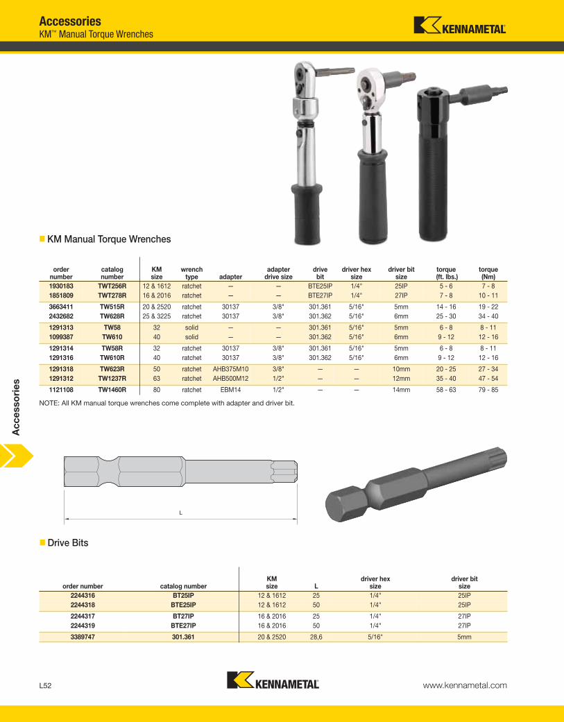
AccessoriesKM™ Manual Torque Wrenches
Ac
ce
sso
rie
s
order number
catalog number
KM size
wrench type adapter
adapter drive size
drive bit
driver hex size
driver bit size
torque(ft. lbs.)
torque (Nm)
1930183 TWT256R 12 & 1612 ratchet — — BTE25IP 1/4" 25IP 5 - 6 7 - 8
1851809 TWT278R 16 & 2016 ratchet — — BTE27IP 1/4" 27IP 7 - 8 10 - 11
3663411 TW515R 20 & 2520 ratchet 30137 3/8" 301.361 5/16" 5mm 14 - 16 19 - 22
2432682 TW628R 25 & 3225 ratchet 30137 3/8" 301.362 5/16" 6mm 25 - 30 34 - 40
1291313 TW58 32 solid — — 301.361 5/16" 5mm 6 - 8 8 - 11
1099387 TW610 40 solid — — 301.362 5/16" 6mm 9 - 12 12 - 16
1291314 TW58R 32 ratchet 30137 3/8" 301.361 5/16" 5mm 6 - 8 8 - 11
1291316 TW610R 40 ratchet 30137 3/8" 301.362 5/16" 6mm 9 - 12 12 - 16
1291318 TW623R 50 ratchet AHB375M10 3/8" — — 10mm 20 - 25 27 - 34
1291312 TW1237R 63 ratchet AHB500M12 1/2" — — 12mm 35 - 40 47 - 54
1121108 TW1460R 80 ratchet EBM14 1/2" — — 14mm 58 - 63 79 - 85
� KM Manual Torque Wrenches
NOTE: All KM manual torque wrenches come complete with adapter and driver bit.
� Drive Bits
order number catalog numberKM size L
driver hex size
driver bit size
2244316 BT25IP 12 & 1612 25 1/4" 25IP
2244318 BTE25IP 12 & 1612 50 1/4" 25IP
2244317 BT27IP 16 & 2016 25 1/4" 27IP
2244319 BTE27IP 16 & 2016 50 1/4" 27IP
3389747 301.361 20 & 2520 28,6 5/16" 5mm
KEN_TOOLINGSYSTEMS11_L052_L053.qxp:WIDIA 11:45 AM Page L52

L53www.kennametal.com
order numberdrive hex bit
catalog number
1863666 986-6
1131354 986-8
1131361 986-10
NOTE: Wrench and drive hex bit must be ordered separately.
wrenchdrive hex bit
catalog number KM32 KM40 KM50 KM63
914-15 986-6 = hex size 6mm 986-8 = hex size 8mm 986-10 = hex size 10mm 986-10 = hex size 10mm
AccessoriesKM-LOC II™ and KM-LOC™ Wrenches
Ac
ce
sso
rie
s
order number catalog numberKM size driver
driver bit size
2906898 TBWLT25IP 12 & 1612 1/4" Hex 25IP
2906899 TBWLT27IP 16 & 2016 1/4" Hex 27IP
3746472 TBWL5H 20 & 2520 3/8" Square 5mm
3336459 TBWL6H 25 & 3225 3/8" Square 6mm
� Thumbwheels
(KM Manual Torque Wrenches continued)
� KM LOC and KM LOC II Wrench
KEN_TOOLINGSYSTEMS11_L052_L053.qxp:WIDIA 11:45 AM Page L53

L54 www.kennametal.com
order number catalog numberwrench set description
1192354 MW-9 set contains (mm) 1,27; 1,5; 2,0; 2,5; 3,0; 4,0; 5,0; 6,0; and 8,0
order number catalog number hex size1138748 170.135 5mm1138755 170.136 6mm
order number catalog numberwrench
description1192321 KW-7A set contains sizes: 5/64, 3/32, 7/64, 1/8, 5/32, 3/16, and 7/32
� Hex Wrench Set • Metric
� T-Handle Hex Wrench • Metric
� T-Handle Wrench Set • Inch
AccessoriesHex Wrench Sets • T-Handle Hex Wrench Sets
Acc
esso
ries
KEN_TOOLINGSYSTEMS11_L054_L055.qxp:WIDIA 2:04 PM Page L54

L55www.kennametal.com
order number catalog number
1963869 driver
order number catalog numberhex size
Torx size
Torx Plus size
1138851 170.179 2,5mm — —
1150198 170.180 3mm — —
1138857 170.181 4mm — —
1962981 BT6 — 6 —
1963853 BT7 — 7 —
1963855 BT8 — 8 —
1963854 BT9 — 9 —
1963856 BT10 — 10 —
1138814 170.175 — 15 —
1138822 170.176 — 20 —
1994654 170.258 — 25 —
1984243 170.256 — 27 —
2244316 BT25IP — — 25IP
2244317 BT27IP — — 27IP
� Universal Bit Driver
� Driver Bit
Universal Bit Drivers • Driver BitsAccessories
Ac
ce
sso
rie
s
KEN_TOOLINGSYSTEMS11_L054_L055.qxp:WIDIA 11:45 AM Page L55

L56 www.kennametal.com
AccessoriesOpen-Ended Wrenches
• Standard open-ended wrenches.
� Wrench OEW • Metric
� Wrench OEW • Inch
order number catalog number DRVS
1284020 OEW9M 9mm
1284011 OEW13M 13mm
1174217 OEW16M 16mm
1197387 OEW19M 19mm
1192371 OEW24M 24mm
1186649 OEW25M 25mm
1284014 OEW30M 30mm
1284015 OEW32M 32mm
order number catalog number DRVS
1025533 OEW044 7/16
1025544 OEW050 1/8
1025546 OEW062 5/8
1025547 OEW068 11/16
1025548 OEW075 3/4
1025550 OEW088 7/8
1025551 OEW094 15/16
1025552 OEW100 1
1025553 OEW106 1 1/16
1025574 OEW112 1 1/8
1025575 OEW119 1 3/16
1025576 OEW125 1 1/4
1025674 OEW138 1 3/8
1025581 OEW150 1 1/2
1025582 OEW162 1 5/8
1025583 OEW168 1 11/16
1025604 OEW175 1 3/4
1025605 OEW188 1 7/8
1025607 OEW225 2 1/4
1025608 OEW250 2 1/2
Ac
ce
sso
rie
s
KEN_TOOLINGSYSTEMS11_L056_L057.qxp:WIDIA 11:46 AM Page L56

L57www.kennametal.com
order number catalog number DSWC
3367387 PSW52M 58,0mm - 62,0mm
1284310 PSW58M 52,0mm - 55,0mm
1192392 PSW68M 68,0mm - 75,0mm
1284311 PSW80M 80,0mm - 90,0mm
order number catalog number DSWC
1013497 PSW350 3 1/2
AccessoriesPin Spanner Wrenches • Hook Spanner Wrenches
• Standard pin spanner wrenches.
� Wrench PSW • Metric
� Wrench PSW • Inch
order number catalog number DSWC
1273813 HSW25M 25,0mm - 28,0mm
1273814 HSW34M 34,0mm - 36,0mm
1192229 HSW45M 45,0mm - 50,0mm
1192230 HSW58M 58,0mm - 62,0mm
1273815 HSW68M 68,0mm - 75,0mm
1192231 HSW80M 80,0mm - 90,0mm
• Standard hook spanner wrenches.
� Wrench HSW • Metric
Ac
ce
sso
rie
s
KEN_TOOLINGSYSTEMS11_L056_L057.qxp:WIDIA 11:46 AM Page L57
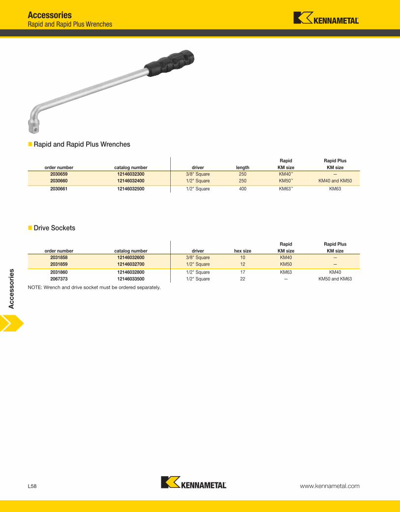
L58 www.kennametal.com
Rapid Rapid Plus
order number catalog number driver length KM size KM size
2030659 12146032300 3/8" Square 250 KM40™ —
2030660 12146032400 1/2" Square 250 KM50™ KM40 and KM50
2030661 12146032500 1/2" Square 400 KM63™ KM63
Rapid Rapid Plus
order number catalog number driver hex size KM size KM size
2031858 12146032600 3/8" Square 10 KM40 —
2031859 12146032700 1/2" Square 12 KM50 —
2031860 12146032800 1/2" Square 17 KM63 KM40
2067373 12146033500 1/2" Square 22 — KM50 and KM63
AccessoriesRapid and Rapid Plus Wrenches
� Rapid and Rapid Plus Wrenches
� Drive Sockets
NOTE: Wrench and drive socket must be ordered separately.
Ac
ce
sso
rie
s
KEN_TOOLINGSYSTEMS11_L058_L059.qxp:WIDIA 11:46 AM Page L58

Experience the advantages at your Authorized Kennametal Distributor or at www.kennametal.com.
www.kennametal.com
ERICKSON™ & KM™
• Most accurate chuck, ≤3μm (.0001"), achieves maximum performance from your cutting edge.
• Inherent dampening design extends tool life and improves surface finish.
• Pre-balanced to high specifications.
• Versatile as a collet chuck with the use of reduction sleeves.
For hydraulic chucks — ERICKSON and KM — the industry names you can trust.
Names You Can Trust
KEN_TOOLINGSYSTEMS11_L058_L059.qxp:WIDIA 11:46 AM Page L59