keith cleensweep tarp system installation & operation … · 2018-01-08 · step 2: a slot must...
TRANSCRIPT

KEITH® CleenSweep® Tarp SystemINSTALLATION & OPERATION MANUAL
Original Instructionswww.keithwalkingfloor.com
©2017 KEITH Manufacturing Co. All Rights Reserved. KEITH, KEITH logo and WALKING FLOOR are registered trademarks of KEITH Manufacturing Co. Equipment manufactured by KEITH Manufacturing Co. is protected by numerous patents both domestic and foreign.
8570101.igs
Revised: 1/8/18
www.keithwalkingfloor.com
KEITH Manufacturing Co.401 N.W. Adler St., P.O. Box 1Madras, OR 97741(800) 547 6161T:(541) 475 3802F:(541) 475 [email protected]

KEITH®
CLEENSWEEP™
TARP SYSTEM
KEITH®
CLEENSWEEP™
TARP SYSTEM
This CleenSweep® Tarp System is warranted to the original purchaser to be free from defects in material and workmanship under normal use for a period of one year from the date of purchase. During the warranty period, and upon proof of purchase, the CleenSweep® Tarp System will be repaired or replaced with the same or similar model.
I have fully read the CleenSweep® Tarp System warranty information and I/we fully understand and agree to the terms of the warranty. SIGNATURE:
WARRANTY
WARRANTY CARDCleenSweep® Tarp System Warranty Registration Card
IT IS EXPRESSLY AGREED THAT THIS SHALL BE THE SOLE AND EXCLUSIVE REMEDY OF THE BUYER. UNDER NO CIRCUMSTANCES SHALL KEITH MFG. CO. BE LIABLE FOR ANY COSTS, LOSS, EXPENSE, DAMAGE, SPECIAL DAMAGES, INCIDENTAL DAMAGES, OR CONSEQUENTIAL DAMAGES ARISING DIRECTLY OR INDIRECTLY FROM THE USE OF THE CLEENSWEEP TARP SYSTEM. WHETHER BASED UPON WARRANTY, CONTRACT NEGLIGENCE OR STRICT LIABILITY.
THE WARRANTY AND LIMITS OF LIABILITY CONTAINED HEREIN ARE IN PLACE OF ALL OTHER WARRANTIES AND LIABILITIES, EXPRESSED OR IMPLIED. ALL IMPLIED WARRANTIES OF MERCHANTABILITY AND FITNESS FOR A PARTICULAR PURPOSE ARE HEREBY DISCLAIMED BY KEITH MFG. CO. AND EXCLUDED FROM THIS WARRANTY. FURTHER, KEITH MFG. CO. DOES NOT WARRANT THAT THE CLEENSWEEP TARP SYSTEM COMPLIES WITH LOCAL, MUNICIPAL, STATE OR FEDERAL CODES, IF ANY AND THE BUYER ALONE IS RESPONSIBLE FOR ANY KNOWLEDGE OF ANY COMPLIANCE WITH ANY SUCH CODES.
This warranty shall not apply to any parts that; (a) have been repaired or altered outside of the CleenSweep® Tarp System; (b) have been subjected to misuse, negligence or accident; or (c) have been used or installed in a manner contrary to CleenSweep® Tarp System instructions.
In certain circumstances some states do not allow the exclusion or limitation of incidental damages, some or all of the above limitations or exclusions may not apply to you. This warranty gives you specific legal rights and you may have other rights that vary from state to state.
If this warranty violates law: To the extent any provision of this warranty contravenes the law of any jurisdiction, that provision shall be inapplicable in such jurisdiction and the remainder of the warranty shall not be affected thereby.
Notice: To validate all warranties, a warranty registration card must be completed and returned to KEITH Mfg. Co. within ten days of purchase. If you did not receive a warranty registration card, contact your dealer immediately.
Purchaser:Address:State/Prov: Country:Postal Code:Original Purchase Date of System: System Serial Number:Dealer Name & Location: Type of Material Unloaded:
Note: To validate the warranty, this registration card must be filled out completely and returned to KEITH Mfg. Co. / KEITH WALKING FLOOR Europe within ten (10) days of purchase and/or installation.
KEITH Manufacturing Co. WORLD HEADQUARTERS [email protected]
KEITH WALKING FLOOR EuropeTHE NETHERLANDS
PO Box 1; 401 NW AdlerMadras, OR 97741 USAPh: (541) 475-3802Fax: (541) 475-2169
Harselaarseweg 1133771 MA BarneveldPh: (+31) (0) 342 42207Fax: (+31) (0) 342-422180
®
®

CONTENTS:
1.0 INTRODUCTION.......................................................................................................
2.0 HYDRAULIC INSTALLATION.................................................................................... 2.1 Tools................................................................................................................ 2.2 Materials......................................................................................................... 2.3 Winch Installation............................................................................................ 2.4 Strap Roller Assembly Installation .................................................................. 2.5 Manifold Installation ........................................................................................ 2.6 Hydraulic Plumbing Installation....................................................................... 2.7 Tarp Installation............................................................................................... 2.8 Winch Brake Adjustment................................................................................. 2.9 CleenSweep® Installation and Operation Instructions..................................... 2.10 System Check ................................................................................................
3.0 OPERATION ............................................................................................................. 3.11 Normal Operation........................................................................................... 3.12 Electric System Manual Override...................................................................
APPENDIX A: Tools................................... ...........................................................................
APPENDIX B: Materials Not Supplied .................................................................................
APPENDIX C: Parts List.......................................................................................................
APPENDIX D: Part Diagrams...............................................................................................
4.0 Pre-2015 KEITH® Hydraulic CleenSweep®................................................................
4.1 Pre-2015 Control Manifold Schematic................................................................. 4.2 Pre-2015 Winch Break Adjustment..................................................................... 4.3 Pre-2015 Tarp Out Installation............................................................................. 4.4 Pre-2015 System Check...................................................................................... 4.5 Pre-2015 Normal Operation................................................................................ 4.6 Pre-2015 Electric System Manual Override........................................................
APPENDIX E: Tools..............................................................................................................
APPENDIX F: Materials Not Supplied..................................................................................
APPENDIX G: Parts List.......................................................................................................
APPENDIX H: Parts Diagrams.............................................................................................
1
2
22267912161718
19
1920
21
22
23
26
29
303132333334
35
36
37
40

5.0 PNEUMATIC INSTALLATION....................................................................................
5.1 Winch Installation............................................................................................ 5.2 Spool Assembly................................................................................................ 5.3 Lubricator and Air Filter Installation................................................................. 5.4 Plumbing Instructions...................................................................................... 5.5 Actuator valve and Lockout Installation........................................................... 5.6 Tarp Installation............................................................................................... 5.7 Tarp Out-Stop Installation................................................................................ 5.8 Oiling Instructions............................................................................................
APPENDIX I: Parts List........................................................................................................
APPENDIX J: Brake Assembly.............................................................................................
42
4345464849505556
57
60
CONTENTS: (Continued)

1
Introduction Hydraulic CleenSweep®
1.0 INTRODUCTIONThis manual explains procedures for installing and operating the KEITH® Hydraulic CleenSweep® Tarp System and the KEITH Pneumatic CleenSweep® Tarp System. Many variables affect the installation, but the general process remains constant. Details of the installation vary, according to trailer features and installer preferences.
An efficient installation requires appropriate tools and accessible materials. A list of tools is found in Appendix A. This kit does not include any hoses - Appendix B lists required materials not supplied. Appendix C contains a list of parts supplied with this kit.
It is strongly recommended that the installers and operators read this entire manual before beginning the installation or operating of the system.
Please direct any questions to KEITH Manufacturing Co. or one of our international offices listed on our website.
WARNING: Always disconnect hydraulic power to the trailer before entering the trailer or working on the CleenSweep® Tarp System components. Failure to do so may result in serious injury or death due to the large forces involved with the CleenSweep® Tarp System.
IMPORTANT: Installing the CleenSweep® Tarp System requires some alterations to your trailer. Changes made without the approval of the trailer manufacturer may void the trailer’s warranty.

2
Installation Hydraulic CleenSweep®
2.0 Hydraulic CleenSweep® Installation WARNING: Always disconnect hydraulic power to the trailer before entering the trailer or working on the CleenSweep® Tarp System components. Failure to do so may result in serious injury or death due to the large forces involved with the CleenSweep® Tarp System.
2.1 Tools Gather tools listed in Appendix A.
2.2 Materials Refer to the part list in Appendix C and verify that all KEITH®-supplied parts are present. A list of parts and materials not supplied by KEITH is found in Appendix B. Hose lengths and tubing bends and lengths will vary depending on the manifold and winch mounting locations and therefore should not be produced until the winch and manifold are mounted and measurements can be taken. Additional fittings (elbows, reducers, adapters, etc…) may be required depending on the particular installation.
2.3 Hydraulic Winch Installation Option 1: Winch mounted below front shield (low-mount)
Figure 1: Winch and manifold mounted below the front shield (low-mount).
8570101.igs

3
Mount the winch to the lower center of the front wall of the trailer. The winch should be under the front shield and must not interfere with the operation of the floor slats – maintain at least 1” (25 mm) clearance between the winch and floor slats. The winch should be mounted with the strap guide up. Ensure all moving parts of the winch have adequate clearance.
Note: Front wall may need to be reinforced to withstand the forces created by the winch.
Option 1 requires the use of the strap roller assembly mounted at the top center of the front wall or top rail – see section 2.4 for installation instructions.
Step 1: Front shield modification: It is recommended that the front shield be hinged or fitted with a door/panel to gain access to the winch after it is installed to facilitate adjustment, inspection and maintenance.
Step 2: A slot must be cut through the front shield for the strap to pass through. The slot must be centered along the path of the strap, from the winch to the strap roller assembly and all sharp edges removed or covered to prevent damage to the strap. Maintain at least 1/2” (13 mm) clearance all around the strap.
Step 3: Locate the center of the front wall of the trailer. Please note that it is crucial that the winch is mounted in the absolute center of the trailer and at a 90-degree angle. If the winch is not mounted square, it will put uneven pressure on the tarp strap.
Step 4: Measure 3 1/2” (89 mm) up from the top of the floor slats to locate the bottom of the base plate. Transfer the winch base plate bolt pattern to the wall and drill two 17/32” (13mm) bolt clearance holes (or four 7/16” (11 mm) bolt clearance holes if installing the SAE mounting version with the 3/8”-16 threaded base plate).
Step 5: Attach the winch to the front wall using 1/2” grade 8+ (M12 class 10.9+) locking fasteners (or appropriate length 3/8” -16 bolts if installing the SAE mounting version with the 3/8” -16 threaded base plate).
Installation - Winch Hydraulic CleenSweep®

4
Option 2: Winch mounted at top of trailer front wall (high-mount)
Figure 2: Winch mounted at top of front wall. Mount the winch to the top center of the front wall of the trailer. The winch should be mounted with the strap guide down. Ensure all moving parts of the winch have adequate clearance.Note: Front wall may need to be reinforced to withstand the forces created by the winch. Option 2 does not require the strap roller assembly because the winch structure with strap guide is designed to locate the tarp at the front wall and stop the tarp when it is fully retracted.
Step 1: Locate the center of the front wall of the trailer. Please note that it is crucial that the winch is mounted in the absolute center of the trailer and at a 90-degree angle. If the winch is not mounted square, it will put uneven pressure on the strap.
Step 2: Transfer the winch base plate bolt pattern to the wall and drill two 17/32” (13 mm) bolt clearance holes (or four 7/16” (11 mm) bolt clearance holes if installing the SAE mounting version with the 3/8”-16 threaded base plate).
Step 3: Attach the winch to the front wall using 1/2” grade 8+ (M12 class 10.9+) locking fasteners (or appropriate length 3/8”-16 bolts if installing the SAE mounting version with the 3/8”-16 threaded base plate).
Installation - Winch Hydraulic CleenSweep®
8570301B.igs
5
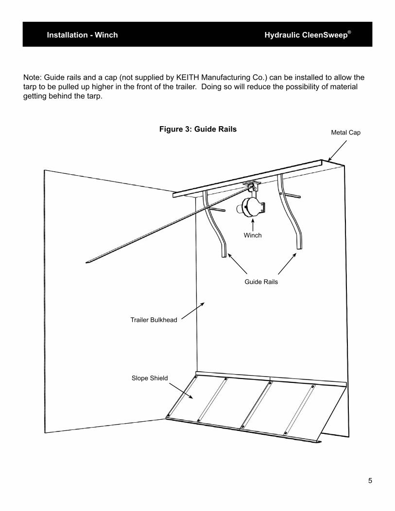
Note: Guide rails and a cap (not supplied by KEITH Manufacturing Co.) can be installed to allow the tarp to be pulled up higher in the front of the trailer. Doing so will reduce the possibility of material getting behind the tarp.
Figure 3: Guide Rails Metal Cap
Guide Rails
Winch
Trailer Bulkhead
Slope Shield
Installation - Winch Hydraulic CleenSweep®

6
2.4 Strap Roller Assembly Installation
Figure 4: Strap roller assembly mounted at top of front wall.
The strap roller assembly is only required for low-mount winch installations.
The strap roller assembly may be mounted at the top of the front wall or to the top rail at the front of the trailer. Please note that it is crucial that the strap roller assembly is mounted in the absolute center of the trailer and at a 90-degree angle. If the strap roller assembly is not mounted square, it will put uneven pressure on the tarp strap. Note: Front wall may need to be reinforced to withstand the forces created by the winch.
Step 1: Locate the top center of the trailer front wall or the center of the top rail.
Step 2: Measure 1 1/2” from the front (if mounting to the top rail) or from the top rail downward to locate the strap roller base mounting location.
Step 3: Transfer the strap roller bracket bolt pattern to the wall or top rail and drill two 7/16” (11 mm) bolt clearance holes (or four 7/16” (11 mm) bolt clearance holes if installing the SAE mounting version with the 3/8”-16 threaded base plate).
Step 4: Attach the strap roller to the front wall using 3/8” grade 5+ (M10 class 8.8+) locking fasteners (or appropriate length 3/8”-16 bolts if installing the SAE mounting version with the 3/8”-16 threaded base plate).
Installation - Strap Roller Hydraulic CleenSweep®

7
2.5 Manifold Installation
Figure 5: Manifold mounted below front shield.
Figure 6: Manifold mounted to exterior front wall on driver’s side.
Installation - Manifold Hydraulic CleenSweep®
8570101.igs
8767601.igs

8
The manifold can be mounted in several locations based on installer preference, trailer construction and other installed equipment. The most common mounting locations are under the front shield, on the driver’s side of the exterior front wall or on the driver’s side landing gear. See Section 2.6 for hydraulic plumbing installation considerations before choosing a location and installing the manifold.
Step 1: If the manifold is mounted below the front shield it is recommended that the front shield and/or trailer wall be hinged or fitted with a door/panel to gain access to the manifold after it is installed to facilitate adjustment, inspection and maintenance.
Step 2: Determine the orientation and location of the manifold and manifold fittings based on hose/tube routing requirements, clearance requirements and valve access. · When mounting the manifold under the front shield position, the manifold and manifold mounting bracket must be installed so that hydraulic hoses cannot interfere with the operation of the floor slats. A manifold distance of 2 1/2” to 3” above the top of the slats works well. · Maintain at least 1” (25 mm) clearance between any part of the CleenSweep® system assembly and the floor slats. Step 3: Attach the manifold mounting bracket to the trailer by welding or using 3/8” (10 mm) nuts, washers, locking washers and bolts of appropriate length (not supplied).
Step 4: The manual override knob on electric systems and the manual valve knob on manual systems must be accessible from the outside of the trailer. This will require a hole through the wall of the trailer or an appropriate access panel in the wall of the trailer, if the manifold is mounted below the front shield. · For manual systems, the knob may be removed temporarily and reattached on the opposite side of the wall after mounting the manifold with the valve body inserted through a 1 1/4” (32 mm) hole in the trailer wall. · An extension (not supplied) may be fitted to the manual valve stem if necessary. The valve stem knob may be removed and the valve stem is threaded ¼”-20 UNC. Step 5: Attach the manifold to the manifold mounting bracket using the supplied M10 x 1.5 x 150mm bolts, locking nuts and washers.
Installation - Manifold Hydraulic CleenSweep®

9
The manifold is plumbed into the hydraulic system, between the pump and the WALKING FLOOR® drive. All fluid traveling to and from the drive goes through the CleenSweep® system manifold first -this requires rerouting some of the existing trailer hydraulic plumbing. Careful planning is necessary before making any modifications to the existing trailer plumbing. Due to the wide variety of existing plumbing configurations and possible CleenSweep® system manifold installation options, specific plumbing details including hose/tube lengths, etc. are not provided.
All ports on the manifold are labeled. There are two ports each for the winch pressure, winch return, pressure out to floor, return from floor, and return to tank to allow several mounting/plumbing options. The manifold is shipped with one of the paired ports plugged but it may be necessary to swap plugs/fittings for certain installations. · All components, lines and fittings must be kept absolutely clean to prevent contamination of the hydraulic system. · Keep bends and fittings to a minimum. · Ensure all hoses and tubes are adequately protected from moving parts and possible damage from material loading by providing at least 1” clearance from moving parts, firmly clamping hoses and tubing in place and using shields or guards where applicable. Use rubber grommets or equivalent protection when routing through cross-members, walls or other structures. · All hoses, tubes and fittings must be suitable for a working pressure of at least 3000 PSI (207 bar). · The fittings supplied on the winch motor and manifold for the winch pressure and return lines are male -6 (3/8”) 37º JIC (ISO 8434-2). · The fittings supplied on the manifold for the Pump-Pressure-In, Pressure-Out-To- Drive, Tank-Return-From-Drive and Return-To-Tank are male -16 (1”) 37º JIC (ISO 8434-2). · Manifold ports are SAE O-ring ports of the same size as the hose/tube fitting. · The manifold is connected to the winch and the trailer hydraulic system according to Table 1.
2.6 Hydraulic Plumbing Installation
Installation - Hydraulic Plumbing Hydraulic CleenSweep®

10
MANIFOLD FITTING: CONNECTS TO:WINCH PRESSURE Male -6 (3/8”) 37º JIC (ISO 8434-2)
Winch motor pressure port (pressure port is the one that will cause counter clockwise spool rotation when viewing winch from motor side) Male -6 (3/8”) 37º JIC (ISO 8434-2)
WINCH RETURN Male -6 (3/8”) 37º JIC (ISO 8434-2)
Winch return portMale -6 (3/8”) 37º JIC (ISO 8434-2)
PRESSURE IN Male -16 (1”) 37º JIC (ISO 8434-2)
Pressure line in from pump
PRESSURE OUTMale -16 (1”) 37º JIC (ISO 8434-2)
Pressure line out to floor drive
TANKMale -16 (1”) 37º JIC (ISO 8434-2)
Tank return line from floor drive
TANKMale -16 (1”) 37º JIC (ISO 8434-2)
Return line to tank
Table 1: Manifold plumbing
Installation - Hydraulic Plumbing Hydraulic CleenSweep®

11
Figure 7: Control manifold hydraulic schematic.
Installation - Hydraulic Plumbing Hydraulic CleenSweep®

12
Please note that tarp poles are not supplied by KEITH Manufacturing Co. For the top pole, located at the top of the tarp, one 2” (50 mm) lightweight metal pipe is recommended. For all other poles, use three 1 ½” (40 mm) pipes.
Step 1: Thread the strap through the strap guide on the winch, through the slot in the front shield (if winch is low-mounted) and through the strap roller (if used).
Step 2: Cut the tarp poles approximately 2” (50 mm) shorter than the inside width of the trailer. Take this measurement just above the trailer floor, at the trailer’s narrowest point.
Step 3: If the tarp is wider than the width of the trailer, cut the tarp to the same width as the inside of the trailer. Use the vertical stitching as a guide and remove half of the material from each side of the tarp.
Note: If you are installing a CleenSweep® into a trailer with a V-FLOOR® system, the tarp will need to be wider than the inside of the trailer because the tarp will conform to the ridges on the floor. For a V-9 system, the tarp should be 6” wider than the inside of the trailer. For a V-18 system, the tarp should be 7” wider.
Step 4: Center the tarp poles in the tarp pockets. The 2” (50 mm) pole should be inserted into the top pocket with the notch in the center. The smaller diameter poles go into the next two pockets down from the top. UHMW strips, similar to what is installed on the bottom of the front slope shield, can also be used as other poles.
Step 5: Keep the tarp poles in place by pop riveting the tarp to the poles—two rivets on each end (not supplied).
Step 6: Find the center of the top tarp pole. Drill 3/8” (9.5 mm) holes through the top pole to attach the U-Bolt. It must be centered and installed so that when the tarp is hanging from the winch, the threads of the U-Bolt are facing downward. If necessary, you can make the notch in the middle of the tarp wider to accommodate the U-Bolt.
Step 7: Place the tarp in the trailer, with the handles facing upward and the 2” (50 mm) top tarp pole towards the front of the trailer.
Step 8: Making sure that the strap is not twisted, wrap it around the pole tightly at least twice and tighten the U-Bolt.
Note: Systems are available in 2.5 or 5 GPM versions. If a galvanized steel pole is used, it is recommended to use the 2.5 GPM version. Either the 2.5 or 5 GPM version may be used if a lightweight metal pole is used.
2.7 Tarp Installation
Installation - Tarp Hydraulic CleenSweep®

13
Installation - Tarp Hydraulic CleenSweep®
A.
Wid
th o
f th
e T
raile
r M
inu
s 1
” (2
5m
m)
B.
2”
(50
mm
)(1 r
eq
uired
) C
. 1
½”
(38
mm
)(3
req
uire
d)
D
. R
ive
t th
e T
arp
to
th
e P
ipe
(4 P
lace
s P
er
Pip
e)
E.
Ce
nte
r th
e P
ipe
s in t
he M
idd
le o
f th
e T
arp
F
. F
or
Sh
ort
er
Tra
ilers
, th
e T
hird P
ipe M
ay B
e M
oved
to
the
Up
per
Po
cke
t G
. T
arp
Ha
nd
les
H.
Use
Stitc
hin
g L
ine
s a
s a
Gu
ide
line
to
Cu
t th
e W
idth
of th
e T
arp
to
fit th
e T
raile
r
No
te:
Cut
Ha
lf o
f th
e M
ate
ria
l O
ff F
rom
Each
Sid
e
Figure 8

14
Installation - Tarp Hydraulic CleenSweep®
U-Bolt Assembly
Center of Tarp
Drill Two 11/32” (10mm) holes
through the top of the pipe for mounting the U-Bolt
If necessary, enlarge notch in the tarp.
Figure 9

15
Installation - Tarp Hydraulic CleenSweep®
Figure 10
U-Bolt Assembly
Strap
Wrap the strap around the pipethree times and secure it to the pipe using the U-Bolt.

16
The winch brake retains the tarp in the retracted position at the top of the front wall during loading, transport and the beginning of the unloading cycle.
Step 1: Retract the tarp to the top of the front wall.
Step 2: Tighten the brake against the strap until it takes approximately 10lbs to pull the CleenSweep® free from the brake.
Step 3: Raise tarp to the parked position. Trim the bottom of the tarp to leave 12” to 14” laying on the floor.
Figure 11: Winch brake
2.8 Winch Brake Adjustment
Installation - Winch Brake Hydraulic CleenSweep®
8570502.igs

17
2.9 CleenSweep® Installation and Operation Instructions
Installation - Tarp Out-Stop Hydraulic CleenSweep®
85869_2
2016 KEITH Mfg. Co. KEITH, KEITH logo and WALKING FLOOR are registered trademarks of KEITH Mfg. Co. Manufactured under license.
® KEITH Mfg. Co.1.800.547.6161www.keithwalking�oor.com
#85869A
85869_1
CleenSweep® Installation and Operation Instructions
1. Attach tarp and retract all the way to the front of the trailer.
2. Cut tarp to length as shown in Fig. A.
3. Unload until top of tarp reaches threshold at rear of trailer (Fig. B).
4. Set strap length by removing “Tarp Out-Stop Bolt.” Adjust strap to proper length and reinstall “Tarp Out- Stop Bolt.”
5. Pull forward far enough to get between load and trailer.
6. Pull tarp and shake to clean.
7. Put tarp into trailer and close door.
8. Retract tarp to load position.
(See CleenSweep® Tarp System Installation and Operation Manual at www.keithwalking�oor.com for more information.)
Adjusting Tarp Length and Setting Proper Strap Length
Top of Tarp
Slope Shield
Top of Tarp
Trailer bulkhead
CleeenSweep® Tarp
Trailer �oor slats
300mm (12”)
Cut tarp so 300mm (12”) is on �oor
Fig. B
Fig. A

18
Inspect all fasteners and fittings for proper torque. Ensure there are no leaks and that all lines are secure before putting the trailer in service.
2.10 System Check
Systems Check Hydraulic CleenSweep®

19
3.0 OPERATION3.1 Normal Operation Step 1: Verify that the tarp is fully retracted prior to loading the trailer. It is suggested that a viewing window/port be installed in the top of the front trailer wall so the operator can verify that the tarp is fully retracted from the winch operating position. Step 2: It is recommended that the trailer is moved forward slightly, near the end of the unloading cycle, to reduce the amount of material unloaded on top of the tarp. Step 3: After unloading the trailer, dislodge the tarp by hand from underneath any material that may have been unloaded on top of the tarp. Do not attempt to pull the tarp from under a load by using the winch or moving the trailer – this may damage the winch, tarp, strap or trailer.
Step 4: Ensure hydraulic power is supplied to the trailer and engage the winch by activating the power switch (electric systems) or pulling out the manual valve knob (manual systems).
Step 5 : The tarp takes 5-15 seconds to retract and when fully retracted, hydraulic fluid delivered to the winch is redirected through the relief valve in the manifold. Full retraction can be verified through the viewing window/port (if installed), otherwise it is signified by an audible bang as the tarp top pole impacts the strap roller, as well as an audible change in the hydraulic system sound as the fluid is directed through the relief valve. At this point, disengage the winch and verify that the tarp is fully retracted.
Operation Hydraulic CleenSweep®

20
3.2 Electric System Manual Override
The electrically-activated valve supplied with electric systems includes a manual override knob that allows the operator to activate the winch without electric power. The manual override is intended for emergency use, not for continuous-duty operation.
Manual Override
Knob
Figure 13: manual override knob on electrically-activated valve.
Figure 14: operation of the manual override knob. Ensure the valve is returned to the normal position after the tarp is retracted.
Operation Hydraulic CleenSweep®

21
TOOL: WHERE USED:End wrenches: Metric
Ratcheting driver with Metric
Hex (Allen) wrenches: Metric
Power drill and the following bits:3/8” (9.5 mm) Tarp top pole for U-bolt attachment7/16” (11 mm) Mounting winch, strap roller, manifold bracket (opt.
– may be welded on)1 1/4” (32 mm) hole saw (optional) Manual valve clearance through trailer wall
(opt. - if manifold is mounted below front shield)Welding equipment (optional) Mounting manifold bracket
(opt. – may be bolted on)Cutting tools (optional) Cutting access panels in trailer wall or front shield
(opt. - if necessary)
APPENDIX A: Tools Hydraulic CleenSweep®

22
MATERIAL: WHERE USED:Hoses/tubing:* *Hose/tube lengths will vary depending on
installation-6 (3/8”) (10 mm) hose/tube with Female-6 (3/8”) 37º JIC (ISO 8434-2) each end
MANIFOLD – TO – WINCH MOTOR: PRES-SURE WINCH MOTOR – TO – MANIFOLD: RETURN
-16 (1”) (25 mm) hose/tube with female-16 (1”) 37º JIC (ISO 8434-2) fitting on manifold end
PUMP – TO – MANIFOLDMANIFOLD – TO – DRIVE: PRESSUREDRIVE – TO – MANIFOLD: RETURNMANIFOLD – TO – TANK
Fittings:* *Required fittings will vary depending on installa-tion
Hose/tube clamps:* *Required clamps will vary depending on instal-lation
Fasteners:* *Fastener lengths and required quantities will vary depending on installation
3/8” (M10) bolts, nuts, washers, locking nuts (or plain nuts w/locking washers)
Mounting strap roller (2 each) and manifold bracket (2 each); use grade 5 (class 8.8) or stronger fasteners.
1/2” (M12) bolts, nuts, washers, locking nuts (or plain nuts w/locking wash-ers)
Mounting winch (2 each); use grade 8 (class 10.9) or stronger fasteners.
rivets Securing tarp poles to tarp
Pipe:2” (50 mm) Top tarp pole (1); Length: 1” (25 mm) shorter
than trailer interior width1 1/2” (40 mm) Middle tarp poles (3);Length: 1” (25 mm) shorter
than trailer interior widthWiring Wiring length will vary depending on installation14 AWG 2-conductor Electric-controlled systems
APPENDIX B: Materials not supplied Hydraulic CleenSweep®

23
APPENDIX C: Parts list Hydraulic CleenSweep®
KITS (INCLUDE ALL REQUIRED PARTS- EXCLUDING TARPS AS NOTED):DESCRIPTION PART #MANUAL ASSEMBLY WITH TARP
Please call a KEITH dealer for a quote.
MANUAL ASSEMBLY WITHOUT TARPELECTRIC 12VOLT ASSEMBLY WITH TARPELECTRIC 24VOLT ASSEMBLY WITH TARPELECTRIC 12VOLT ASSEMBLY WITHOUT TARPELECTRIC 24VOLT ASSEMBLY WITHOUT TARP
PARTS (INCLUDED IN KITS AS REQUIRED):E= FOR ELECTRIC KITS ONLY
ID# QTY DESCRIPTION PART #
1 1 Hydraulic Winch Assembly 08387701
2 1 WINCH BASE PLATE, UNIVERSAL MOUNT 08551301
3 1 Brake for Winch 090952014 2 Brake Holding Nut for Winch 08418801
5 4 Roll Pin 1/4 x 1 86651425
6 2 Brake Holding Mount 08418901
8 4 Lock Washer - M10 87076500
9 4 Hex Bolt - M10 x 1.5 x 20 87008470
10 8 Hex Bolt - M6 x 1 x 20 87002500
11 8 Lock Washer - M6 87075500
12 1 BOLT HEX GR5 ZN 1/4-20 X 3.25 86421500
13 1 WASHER LOCK 1/4" 86551500
14 1 SHAFT EXTENSION, V-SWEEP WINCH 06932001
15 2 NUT HEX NYLOCK 8mm 87101000
16 1 BEARING FLANGE ABEC-1 2-BOLT 85818617
17 1 Support Plate for Winch 08418601
18 2 Hex Socket Countersunk Head Cap Screw - M8x20 87701599
19 1 SHOULDER SCREW, BOLT-ON WINCH SPOOL 06175401
20 3 Flat Washer 96550552
21 3 Hex Socket Head Cap Screw - M6x1 x 10 87009009
22 1 WINCH SPOOL WELDMENT, BOLT-ON 08549601
23 1 Motor Mount Winch 08418501
24 2 BOLT FLOOR 12MMX40MM 87703060
25 2 NUT HEX NYLOCK 12mm 87102500
26 1 CHAR-LYNN HYD MOTOR, H SERIES 85819475
27 2 06-10 F5OX-S STRAIGHT THREAD CONNECTOR MJIC X M O-RING 84684100
28 2 Hex Bolt - M6 x 1 x 110 87005101
29 3 NUT HEX NYLOCK 6mm 87100500
30 1 Hex Bolt - M6 x 1 x 70 87004570

24
37 1 STRAP ROLLER ASSEMBLY 06250301INCLUDES ITEMS 38-44
38 1 STRAP ROLLER 0579550139 1 STRAP ROLLER BRACKET 0625040140 1 STRAP ROLLER BRACKET BASE PLATE NOT REQ.41 1 STRAP ROLLER BUSHING 0581340143 1 BOLT HEX M12 x 1.75 x 90mm 8701340044 1 NUT HEX NYLOCK M12 x 1.75 87102500
45 1 HYDRAULIC MANIFOLD ASSEMBLY (ELECTRIC)E
****************** OR ************************************HYDRAULIC MANIFOLD ASSEMBLY (MANUAL)
05973301************05973304
INCLUDES ITEMS 46-5546 1 MANIFOLD BODY 0597160147 4 HEX UNION,
-16 37º JIC X -16 SAE O-RING84685400
APPENDIX C: Parts list (continued) Hydraulic CleenSweep®
31 2 Strap Guide for Winch #08387701 08419101
32 1 M10 Allthread x 281mm 11-1/16” 08553901
33 2 Flat Washer 87076000
34 2 NUT HEX 10MM 87101500
35 2 NUT HEX NYLOCK 10mm 87102000
36 1 2" STRAP FOR 6117201/02 85811075

25
48 2 HEX UNION,-6 37º JIC X -6 SAE O-RING 8468400049 7 8 mm EXPANDER PLUG MB 800-080 8510113050 2 PLUG, HEX SOCKET,-16 SAE O-RING 8468790051 2 PLUG, HEX SOCKET,-6 SAE O-RING 8468740052 1 PRIORITY FLOW CONTROL
(5 GPM), FREA-XAN-5.085101045
53 2 CHECK VALVE CV08-20-0-N-25 8510360154 1 RELIEF VALVE RV08-20H-0-N-18/800 8510755555 1 CART. VALVE
SV10-40M-0-N-0 (ELECTRIC) E ************************ OR ************************** CART. VALVE, 4-WAY PULL MP10-40K-0-N (MANUAL)
85108800
************85104949
56 1 TARP, 18 OZ. VINYL, STANDARDTRIM-TO-FIT (NOT PICTURED)
85811120
57 1 U-Bolt Assembly Metric (Not Pictured) 8667111258 1 E COIL 12V WEATHERPROOF 4303712
(NOT PICTURED)*************************OR*****************************COIL 24V WEATHERPROOF 4303724(NOT PICTURED)
85601805
************85600250
59 1 E Connector Kit: Deutch DT06-25 (NOT PICTURED)
06714701
62 1 E BUTTON START W/BOX XALD101(NOT PICTURED)
85791635
63 1 MANIFOLD MOUNTING BRACKET,STEEL (NOT PICTURED)
06033101
64 1 MANIFOLD MOUNTING BRACKET,ALUMINUM (NOT PICTURED)
06033102
65 2 BOLT HEX 10.9 M10 x 150mm (NOT PICTURED) 8701160266 2 WASHER FLAT M10 (NOT PICTURED) 8707600067 2 NUT HEX NYLOCK M10 (NOT PICTURED) 87102000
APPENDIX C: Parts list (continued) Hydraulic CleenSweep®

26
APPENDIX D: Part diagrams Hydraulic CleenSweep®
1
2
4
5
631
27
28
26
2425
2220 211918 2317
1615
1413
12
11
10 9
8 29
32
333435
85707-1B
3

27
APPENDIX D: Part diagrams (continued) Hydraulic CleenSweep®

28
APPENDIX D: Part diagrams (continued) Hydraulic CleenSweep®

29
Section:2 Pre-2015 CleenSweep® Tarp System
6169902.igs
WARNING: Always disconnect hydraulic power to the trailer before entering the trailer or working on the CleenSweep® Tarp System components. Failure to do so may result in serious injury or death due to the large forces involved with the CleenSweep® Tarp System.
www.keithwalkingfloor.com
KEITH Manufacturing Co.401 N.W. Adler St., P.O. Box 1Madras, OR 97741(800) 547 6161T:(541) 475 3802F:(541) 475 [email protected]

30
4.1 Control manifold hydraulic schematic.
Installation - Hydraulic Plumbing Pre-2015 Hydraulic CleenSweep
Figure: 1

31
The winch brake retains the tarp in the retracted position at the top of the front wall during loading, transport and the beginning of the unloading cycle.
During loading, the tarp must conform to the load and the front wall of the trailer. The brake must release a short length - usually less than 12” (305 mm) – of strap from the spool while maintaining sufficient (but not excessive) tension on the strap. Excessive tension may cause the tarp pole to bend or restrict the tarp from coming out with the load.
Do not tighten the spring bolt more than 2 turns between testing.
Step 1: Begin adjustment by pulling the tarp out so that it is approximately 15 feet (4600 mm) from being fully retracted and adjust the 5/16”-18 spring bolt so the roller just touches the strap roll – this will ensure the spring bolt is not initially over-tightened which may cause damage.
Step 2: Retract the tarp and verify that the tarp will stay in the retracted position. Test by hanging a 10 lb (7 kg) object from the top pole at the strap.
Step 3: Adjust as necessary to achieve sufficient strap tension and tighten the jam-nut before operating the winch.
Step 4: Raise tarp to the parked position. Trim the bottom of the tarp to leave 12” to 14” laying on the floor.
Figure 2: Winch brake
4.2 Pre-2015 Winch Brake Adjustment
Installation - Winch Brake Pre-2015 Hydraulic CleenSweep®

32
Installation - Tarp Out-Stop Pre-2015 Hydraulic CleenSweep®
4.3 Tarp Out-Stop Installation
Figure 3: Tarp out-stop installation. The tarp out-stop prevents the tarp from coming completely out the back of the trailer during unloading.
Step 1: Pull the tarp out the back of the trailer until it touches the ground with the strap pulled tight.
Step 2: At the winch, install a 1/4”-20 X 2 3/4” bolt through the slot in the spool. Holding the bolt tight against the strap roll, tighten the bolt with a 1/4”-20 low-profile locking nut.
Step 3: After tightening the bolt, tap it down against the strap roll with a hammer or mallet – this recesses the bolt so there is not a bump in the strap roll.
Step 4: Verify that the tarp stops when it touches the ground with the strap pulled tight. Small adjustments can be made by wrapping more or less strap around the top pole under the U-Bolt.

33
Operation Pre-2015 Hydraulic CleenSweep®
Inspect all fasteners and fittings for proper torque. Ensure there are no leaks and that all lines are secure before putting the trailer in service.
4.4 System Check
4.5 Normal Operation Step 1: Verify that the tarp is fully retracted prior to loading the trailer. It is suggested that a viewing window/port be installed in the top of the front trailer wall so the operator can verify that the tarp is fully retracted from the winch operating position. Step 2: It is recommended that the trailer is moved forward slightly, near the end of the unloading cycle, to reduce the amount of material unloaded on top of the tarp. Step 3: After unloading the trailer, dislodge the tarp by hand from underneath any material that may have been unloaded on top of the tarp. Do not attempt to pull the tarp from under a load by using the winch or moving the trailer – this may damage the winch, tarp, strap or trailer.
Step 4: Ensure hydraulic power is supplied to the trailer and engage the winch by activating the power switch (electric systems) or pulling out the manual valve knob (manual systems).
Step 5 : The tarp takes 5-15 seconds to retract and when fully retracted, hydraulic fluid delivered to the winch is redirected through the relief valve in the manifold. Full retraction can be verified through the viewing window/port (if installed), otherwise it is signified by an audible bang as the tarp top pole impacts the strap roller, as well as an audible change in the hydraulic system sound as the fluid is directed through the relief valve. At this point, disengage the winch and verify that the tarp is fully retracted.

34
Operation Pre-2015 Hydraulic CleenSweep®
4.6 Electric System Manual Override
The electrically-activated valve supplied with electric systems includes a manual override knob that allows the operator to activate the winch without electric power. The manual override is intended for emergency use, not for continuous-duty operation.
Manual Override
Knob
Figure 4: manual override knob on electrically-activated valve.
Figure 5: operation of the manual override knob. Ensure the valve is returned to the normal position after the tarp is retracted.

35
TOOL: WHERE USED:End wrenches:
7/16” 1/4”-20 nuts & bolts (Tarp out-stop)1/2” 5/16”-18 nuts (Spring bolt jam-nut, U-bolt nuts)
9/16” 3/8”-16 nuts & bolts (Base plates, manifold bracket)
5/8” -6 (3/8”) port/hose/tube fittings11/16” -6 (3/8”) port/hose/tube fittings3/4” 1/2”-13 nuts & bolts
(Strap roller nut & bolt, motor nuts)1” Control valve, relief valve
1 3/8” -16 (1”) port/hose/tube fittings1 1/2” -16 (1”) port/hose/tube fittings
Ratcheting driver with the following sockets:
7/16” 1/4”-20 nuts & bolts (Tarp out-stop)1/2” 5/16”-18 nuts (Spring bolt jam-nut, U-bolt nuts)
9/16” 3/8”-16 nuts & bolts (Strap Roller, manifold bracket)3/4” 1/2”-13 nuts & bolts (Strap roller nut & bolt, motor
nuts, mounting winch)Hex (Allen) wrenches:
1/8” #10-24 button head socket screws (SAE strap roller bracket)
5/32” 1/4” button head socket screws (strap/spool attach)
1/4” -6 port plugs, 5/16”-18 socket head cap screw (spring bolt)
5/16” 1/2”-13 countersunk bolts (motor bolts)5/8” -16 port plugs
Power drill and the following bits:3/8” (9.5 mm) Tarp top pole for U-bolt attachment7/16” (11 mm) Mounting winch, strap roller, manifold bracket (opt.
– may be welded on)1 1/4” (32 mm) hole saw (optional) Manual valve clearance through trailer wall
(opt. - if manifold is mounted below front shield)Welding equipment (optional) Mounting manifold bracket
(opt. – may be bolted on)Cutting tools (optional) Cutting access panels in trailer wall or front shield
(opt. - if necessary)
APPENDIX E: Tools Pre-2015 Hydraulic CleenSweep®

36
MATERIAL: WHERE USED:Hoses/tubing:* *Hose/tube lengths will vary depending on
installation-6 (3/8”) (10 mm) hose/tube with Female-6 (3/8”) 37º JIC (ISO 8434-2) each end
MANIFOLD – TO – WINCH MOTOR: PRES-SURE WINCH MOTOR – TO – MANIFOLD: RETURN
-16 (1”) (25 mm) hose/tube with female-16 (1”) 37º JIC (ISO 8434-2) fitting on manifold end
PUMP – TO – MANIFOLDMANIFOLD – TO – DRIVE: PRESSUREDRIVE – TO – MANIFOLD: RETURNMANIFOLD – TO – TANK
Fittings:* *Required fittings will vary depending on installa-tion
Hose/tube clamps:* *Required clamps will vary depending on instal-lation
Fasteners:* *Fastener lengths and required quantities will vary depending on installation
3/8” (M10) bolts, nuts, washers, locking nuts (or plain nuts w/locking washers)
Mounting strap roller (2 each) and manifold bracket (2 each); use grade 5 (class 8.8) or stronger fasteners.
1/2” (M12) bolts, nuts, washers, locking nuts (or plain nuts w/locking wash-ers)
Mounting winch (2 each); use grade 8 (class 10.9) or stronger fasteners.
rivets Securing tarp poles to tarp
Pipe:2” (50 mm) Top tarp pole (1); Length: 1” (25 mm) shorter
than trailer interior width1 1/2” (40 mm) Middle tarp poles (3);Length: 1” (25 mm) shorter
than trailer interior widthWiring Wiring length will vary depending on installation14 AWG 2-conductor Electric-controlled systems
APPENDIX F: Materials not supplied Pre-2015 Hydraulic CleenSweep®

37
APPENDIX G: Parts list Pre-2015 Hydraulic CleenSweep®
KITS (INCLUDE ALL REQUIRED PARTS- EXCLUDING TARPS AS NOTED):DESCRIPTION PART #MANUAL ASSEMBLY WITH TARP
Please call a KEITH dealer for a quote.
MANUAL ASSEMBLY WITHOUT TARPELECTRIC 12VOLT ASSEMBLY WITH TARPELECTRIC 24VOLT ASSEMBLY WITH TARPELECTRIC 12VOLT ASSEMBLY WITHOUT TARPELECTRIC 24VOLT ASSEMBLY WITHOUT TARP
PARTS (INCLUDED IN KITS AS REQUIRED):E= FOR ELECTRIC KITS ONLYID # QTY DESCRIPTION PART #
*SAE MOUNTING
UNIVERSAL MOUNTING
1 1 HYDRAULIC WINCH ASSEMBLY 05942301 06250201INCLUDES ITEMS 2-36
2 1 ROLLER, BRAKE 06049201 060492013 1 ROLLER AXLE, BRAKE 06093401 060934014 1 SPRING SPACER, BRAKE 06117101 061171015 2 SWING ARM WELDMENT, BRAKE 06119201 061192016 1 WINCH MOTOR MOUNT 06126701 061267017 1 SUPPORT, WINCH STRAP GUIDE AND BRAKE 06126801 061268018 1 WINCH BASE PLATE 06126901 062505019 2 WINCH STRAP GUIDE 06127301 06127301
10 2 SPACER, WINCH STRAP GUIDE 06127401 0612740111 1 SPRING MOUNT, BRAKE 06127510 0612751012 1 SWING ARM SHAFT, BRAKE 06127601 0612760113 2 SHAFT SPACER, BRAKE 06127701 0612770114 1 WINCH SPOOL WELDMENT,
BOLT-ON06175301 06175301
15 1 SHOULDER SCREW, BOLT-ON WINCH SPOOL 06175401 0617540116 1 SPRING 105-505 84452610 8445261017 2 6400-06-10 ST THREAD
CONNECTOR MJIC X M ORING84684100 84684100
18 2 BUSHING SINTERED SF-1620-8 85811020 8581102019 1 STRAP NYLON CSW 2”X75’
(NOT PICTURED)85811075 85811075

38
20 1 CHAR-LYN HYDRAULIC MOTOR 101-1820-009 H-SERIES
85819475 85819475
21 3 SCREW BUTTON ZN 1/4”-20 X 3/8” 86404312 8640431222 2 BOLT HEX GR5 ZN 1/4”-20 X 1” 86414050 8641405023 1 BOLT HEX GR5 ZN 1/4”-20 X 1-1/4” 86415500 8641550024 1 BOLT HEX GR5 ZN 1/4”-20 X 2-3/4” 86420500 8642050025 2 BOLT HEX GR5 ZN 1/4”-20 X 4-1/2” 86424000 8642400026 1 BOLT SOCKET HEAD ZN 5/16”-18 X 4.5” 86432511 8643251127 4 BOLT HEX GR5 ZN 3/8”X3/4” 86437000 8643700028 3 WASHER FLAT #12 SAE 86550552 8655055229 1 WASHER FLAT 1/4” 86551000 8655100030 3 WASHER FENDER 5/16” X 1-1/4” 86552530 8655253031 4 WASHER LOCK 3/8” 86555000 8655500032 2 NUT HEX NYLOCK 1/4”-20 86626000 8662600033 4 NUT HEX NYLOCK JAM NUT1/4”-20 86626030 8662603034 1 NUT HEX 5/16”-18 86627000 8662700035 2 NUT HEX NYLOCK 1/2” 86629500 8662950036 2 BOLT FLOOR GR8 1/2” X 1-3/4” 87420100 87420100
36A 2 WASHER LOCK 1/4” 86551500 8655150036B 1 HEX NUT - NYLON LOCK - 5/16 - 18 TOP
INSERT TYPE86627500 86627500
37 1 STRAP ROLLER ASSEMBLY 05943001 06250301INCLUDES ITEMS 38-44
38 1 STRAP ROLLER 05795501 0579550139 1 STRAP ROLLER BRACKET 05796201 0625040140 1 STRAP ROLLER BRACKET BASE PLATE 05797701 NOT REQ.41 1 STRAP ROLLER BUSHING 05813401 0581340142 4 SCREW BUTTON #10-24 X 5/8” 86404350 NOT REQ.43 1 BOLT HEX GR8 1/2”-13 X 3 1/2” 86456500 8645700044 1 NUT HEX NYLOCK 1/2”-13 86629500 86629500
45 1 HYDRAULIC MANIFOLD ASSEMBLY (ELECTRIC)E
****************** OR ************************************HYDRAULIC MANIFOLD ASSEMBLY (MANUAL)
05973301************05973304
05973301************05973304
INCLUDES ITEMS 46-5546 1 MANIFOLD BODY 05971601 0597160147 4 HEX UNION,
-16 37º JIC X -16 SAE O-RING84685400 84685400
APPENDIX G: Parts list (continued) Pre-2015 Hydraulic CleenSweep®

39
48 2 HEX UNION,-6 37º JIC X -6 SAE O-RING 84684000 8468400049 7 8 mm EXPANDER PLUG MB 800-080 85101130 8510113050 2 PLUG, HEX SOCKET,-16 SAE O-RING 84687900 8468790051 2 PLUG, HEX SOCKET,-6 SAE O-RING 84687400 8468740052 1 PRIORITY FLOW CONTROL
(5 GPM), FREA-XAN-5.085101045 85101045
53 2 CHECK VALVE CV08-20-0-N-25 85103601 8510360154 1 RELIEF VALVE RV08-20H-0-N-18/800 85107555 8510755555 1 CART. VALVE
SV10-40M-0-N-0 (ELECTRIC) E ************************ OR ************************** CART. VALVE, 4-WAY PULL MP10-40K-0-N (MANUAL)
85108800
************85104949
85108800
************85104949
56 1 TARP, 18 OZ. VINYL, STANDARDTRIM-TO-FIT (NOT PICTURED)
85811120 85811120
57 1 U-BOLT ASSEMBLY (NOT PICTURED) 86671100 8667110058 1 E COIL 12V WEATHERPROOF 4303712
(NOT PICTURED)*************************OR*****************************COIL 24V WEATHERPROOF 4303724(NOT PICTURED)
85601805
************85600250
85601805
************85600250
59 1 E Connector Kit: Deutch DT06-25 (NOT PICTURED)
06714701 06714701
62 1 E BUTTON START W/BOX XALD101(NOT PICTURED)
85791635 85791635
63 1 MANIFOLD MOUNTING BRACKET,STEEL (NOT PICTURED)
06033101 06033101
64 1 MANIFOLD MOUNTING BRACKET,ALUMINUM (NOT PICTURED)
06033102 06033102
65 2 BOLT HEX GR5 ZN 3/8” X 5 3/4” (NOT PIC-TURED)
86446012 86446012
66 2 WASHER FLAT 3/8” (NOT PICTURED) 86554000 8655400067 2 NUT HEX NYLOCK 3/8” (NOT PICTURED) 86626000 86626000
APPENDIX G: Parts list (continued) Pre-2015 Hydraulic CleenSweep®

40
APPENDIX H: Part diagrams Pre-2015 Hydraulic CleenSweep®
1
25
20
35
12
28
21
15
24
17
23
30
2927
31
8
33
3
2
26
33
16
11
32
718
13
10
229
6
36SEE NOTE*
*NOTE*: WINCH ASSEMBLIES (ITEM 1) 5942301 & 6250201 ARE IDENTICAL EXCEPT FOR THEIR MOUNTING METHODS:-ASSEMBLY 5942301 CONTAINS BASE PLATE (ITEM 8) 6126901 WHICH HAS FOUR 3/8"-16 TAPPED MOUNTING HOLES;-ASSEMBLY 6250201 CONTAINS BASE PLATE (ITEM 8) 6250501 WHICH HAS TWO CLEARANCE HOLES FOR 1/2" (M12) MOUNTING BOLTS;-ALL OTHER PARTS ARE INTERCHANGEABLE.
4
14
36A
34
36B
22
61896B
5

41
APPENDIX H: Part diagrams (continued) Pre-2015 Hydraulic CleenSweep®

42
KEITH®
CleenSweep® Installation Instructions Pneumatic Version
5.0

43
Installation of Winch System and Plumbing of Trailer Pneumatic CleenSweep®
5.1 Step 1: Mounting of Winch Frame/Backing Plate
Mount winch frame to the underside of the top rail channel at the front of the trailer. If trailer does not have a top rail, a mounting box will need to be constructed and attached to the trailer.
• Locate the center of the top rail. Please note that it is crucial that the winch is mounted in the absolute center of the trailer and at a 90 degree angle. If the winch is not mounted square, it will put uneven pressure on the tarp strap.
• Measure 1 ¼” back from the front bulkhead and use the winch mount support as a template to drill bolt holes.
Center of Trailer’s Top Rail
Winch Mount Support

44
Installation of Winch Pneumatic CleenSweep®
Step 2:
• Bolt winch to winch mount support using the 3/8” (10mm) bolts, double checking that it is centered and square in the trailer. Washers are not needed because both the winch mount support and winch frame are steel.
• Use a ¾” wrench to remove strap spool, providing access to tighten mounting bolts with socket wrench.
3/8” (10mm) Bolts
1/2” Spool Bolt
1/2” Spool Nut
Spool Assembly

45
Reinstall Spool Assembly Pneumatic CleenSweep®
5.2 Step 3:
• Bolt winch to winch mount support using the 3/8” (10mm) bolts, double checking that it is centered and square in the trailer. Washers are not needed because both the winch mount support and winch frame are steel.
• Use a ¾” wrench to remove strap spool, providing access to tighten mounting bolts with socket wrench.
1 1/4” (32mm) Winch Mount Support
Front Bulkhead

46
Installation of Lubricator & Air Filter Pneumatic CleenSweep®
5.3 Step 4:
• Install bracket mount to the top rail or mounting box approximately 18” to the left of the CleenSweep® winch. Make sure the air hose will still be easily accessible. Note that the bracket design is tilted for easy filling of lubricator.
• Drill a ¾” hole in the top portion of the trailer wall near the bracket mount. If the trailer has front ribs, it is easiest to drill the hole in one of the ribs and thread the air hose through to the bottom of the trailer. If trailer walls do not have ribs, run the air hose through one of the corner braces and attach with hose clamps.
• Install grommet into hole in trailer wall to protect air hose. Feed air hose through hole leaving approximately 18” remaining at top.
• Decide at what angle you want the air fittings for the air hose. Note that it is easier to tighten the fittings before mounting the lubricator and air filter assembly. Fill lubricator with the lubricant supplied before mounting. Lubricant typically lasts 6 to 8 months, depending upon use. Always regularly check the lubricant and use ATL004 or equivalent.
• Bolt lubricator and air filter assembly to bracket mount, making sure that the bottom of the lubricator is not lower than the winch. Also make sure that lubricator and air filter assembly is not installed more than four-feet away from the winch’s air motor to ensure proper lubrication.
Set lubricant regulator by opening the lubricator valve completely (3 ½ to 4 ½ turns counter-clockwise.) The valve is located on the top of the lubricator. See diagram 5.8 page 56.
Note: See figure on next page

47
Installation of Lubricator & Air Filter Pneumatic CleenSweep®
Lubricator & Air Filter AssemblyNote: Lubricator & Air Filter Bracket Mount is mounted at an angle.

48
Plumbing of Lubricator & Air Filter Pneumatic CleenSweep®
5.4 Step 5:
• Cut air hose and attach it to inlet side of the air filter.
• Measure area between fitting on lubricator and fitting on the winch’s air motor. Cut air hose to the appropriate length. Place approximately 20-30 drops of lubricant into the air hose. Attach the air hose to the fittings from the lubricator to the air motor.
Lubricator & Air Filter Assembly
Corner Wall Post
Grommet Protecting Air Hose
Air Hose
Air Hose
Winch Assembly

49
Installation of Actuator Valve & Lock-Out Pneumatic CleenSweep®
5.5 Step 6:
• Determine location of actuator valve. Installation is recommended at one of two locations: • It can be installed on the driver’s side, near the front of the trailer. If this location is chosen, it is a good idea to have a sight hole so that you can see the CleenSweep® system as it works to ensure it is properly set. • It can be installed at rear of trailer, allowing you to watch the CleenSweep® system properly retract to the ready-position before closing the trailer door.
• Drill ¾” hole to accommodate the actuator valve. If it is located at the front of the trailer, drill the hole under the slope shield. Install the lock-out system over the threads before installing the nut. The lock-out system prevents anyone from activating the actuator button when conducting maintenance on the winch system. Make sure the horizontal slot on the actuator valve lock-out is located at the top of the button to ensure the lock-out does not fall out.
Lubricator & Air Filter Assembly
Actuator Valve
Actuator Valve Lock-Out Cover & Lock-Out
Pressure Protection Air Valve
Shared Connection to the Trailer Air Tank

50
Plumbing of Actuator Valve Pneumatic CleenSweep®
Step7:
• Locate the trailer air tanks. If there is an outlet without a valve, you can plumb into it. If not, you will have to create an outlet, using a T-fitting. Outlet must be a “live” outlet, meaning it will have air pressure at all times.
• Attach the pressure protection air valve to the outlet. Note that it may be necessary to reduce the outlet to accommodate the ¼” fitting of the pressure protection air valve. Properly attach all plumbing valves using Teflon tape.
• Begin threading air hose under trailer frame from actuator valve to air tank. Attach air hose to pressure protection air valve.
• Secure air hose to the trailer frame with zip ties.
• If actuator valve is installed near the front of the trailer, run the air hose under slope shield. Make sure all air hoses are clear of the floor slats when they are in the forward most position. Attach air hose from tank to the inlet on the actuator valve.
Attach air hose from tank to the inlet on the actuator valve. Attach the air hose from the air filter to the actuator valve outlet.
5.6 Step 8: Tarp Installation
Please note that tarp poles are not supplied by KEITH Manufacturing Co. For the top pole, located at the top of the tarp, one 2” (50 mm) lightweight metal pipe, is recommended. For all other poles, use three 1 ½” (40 mm) pipes.
Step 1: Thread the strap through the strap guide on the winch, through the slot in the front shield (if winch is low-mounted) and through the strap roller (if used).
Step 2: Cut the tarp poles approximately 1” (25 mm) shorter than the inside width of the trailer. Take this measurement just above the trailer floor, at the trailer’s narrowest point. If using metal poles, cut them 2” (50 mm) shorter than the inside width of the trailer.
Step 3: If the tarp is more than 3” (75 mm) wider than the width of the trailer, cut the tarp to the same width as the inside of the trailer. Use the vertical stitching as a guide and remove half of the material from each side of the tarp.

51
Tarp Assembly & Installation Pneumatic CleenSweep®
Note: If you are installing a CleenSweep® into a trailer with a V-FLOOR® system, the tarp will need to be wider than the inside of the trailer because the tarp will conform to the ridges on the floor. For a V-9 system, the tarp should be 6” wider than the inside of the trailer. For a V-18 system, the tarp should be 7” wider.
Step 4: Center the tarp poles in the tarp pockets. The 2” (50 mm) pole should be inserted into the top pocket with the notch in the center. The smaller diameter poles go into the next two pockets down from the top and either in the third or fourth pocket down from the top, depending on the height of the trailer. UHMW strips, similar to what is installed on the bottom of the front slope shield, can also be used as other poles.
Step 5: Keep the tarp poles in place by pop riveting the tarp to the poles—two rivets on each end (not supplied).
Step 6: Find the center of the top tarp pole. Drill 3/8” (9.5 mm) holes through the top pole to attach the U-Bolt. It must be centered and installed so that when the tarp is hanging from the winch, the threads of the U-Bolt are facing downward. If necessary, you can make the notch in the middle of the tarp wider to accommodate the U-Bolt.
Step 7: Place the tarp in the trailer, with the handles facing upward and the 2” (50 mm) top tarp pole toward the front of the trailer.
Step 8: Making sure that the strap is not twisted, wrap it around the pole tightly at least twice and tighten the U-Bolt.

52
Tarp Assembly & Installation Pneumatic CleenSweep®
A.
Wid
th o
f th
e T
raile
r M
inu
s 1
” (2
5m
m)
B.
2”
(50
mm
)(1 r
eq
uired
) C
. 1
½”
(38
mm
)(3
req
uire
d)
D
. R
ive
t th
e T
arp
to
th
e P
ipe
(4 P
lace
s P
er
Pip
e)
E.
Ce
nte
r th
e P
ipe
s in t
he M
idd
le o
f th
e T
arp
F
. F
or
Sh
ort
er
Tra
ilers
, th
e T
hird P
ipe M
ay B
e M
oved
to
the
Up
per
Po
cke
t G
. T
arp
Ha
nd
les
H.
Use
Stitc
hin
g L
ine
s a
s a
Gu
ide
line
to
Cu
t th
e W
idth
of th
e T
arp
to
fit th
e T
raile
r
No
te:
Cut
Ha
lf o
f th
e M
ate
ria
l O
ff F
rom
Each
Sid
e

53
Tarp Assembly & Installation Pneumatic CleenSweep®
U-Bolt Assembly
Center of Tarp
Drill Two 11/32” (10mm) holes
through the top of the pipe for mounting the U-Bolt
If necessary, enlarge notch in the tarp.

54
Tarp Assembly & Installation Pneumatic CleenSweep®
Wrap the strap around the pipethree times and secure it to the pipe using the U-Bolt.
U-Bolt Assembly
Strap

55
Installation of Tarp Stop Pneumatic CleenSweep®
5.7
• Pull the tarp out the back of the trailer until approximately 24 inches (610mm) remain inside the trailer.
• At the spool assembly install ¼” (6mm) bolt through the slots on either side of the spool, holding the bolt tight against the roll of strapping. Tighten the bolt. Once the bolt is tight, tap the bolt against the spool with a hammer. This recesses the bolt so that there is no bump in the roll of strapping, which could affect the operation of the brake. The tarp stop prevents the tarp from coming completely out of the trailer during unloading.
Tarp Stop Bolt

56
Check Lubricator for Proper Oiling Pneumatic CleenSweep®
5.8
Check that the lubricant bottle has been filled and that the regulator has been fully opened. Refer to instructions on page 46.
To ensure the motor is well lubricated before starting normal operation. Pull the tarp out to the back of the trailer and retract several times by pushing and holding the valve actuator button.

57
APPENDIX I: Parts List Pneumatic CleenSweep®
ID #
Quantity Description Part Number Notes
1 1 Winch Assembly 05214401 - - Includes Items 2-3 7 - 2 1 Winch Frame 05214601
3 1 Winch Mount Support 05215001 4 1 Spool Modification 05215501 5 1 Friction Brake Assembly 05214501 - Includes Items 6-14 6 1 Friction Brake 05216501 6A 1 Brake Mounting Lug 05985701
7 2 Nut Hex 1/4" Nylock 86626000 8 3 Brake Roller 05216701 9 1 Brake Roller Pin 05216801 10 2 Eccentric Set Collar 05216901 11 1 Hinge Pin Brake 05217001 12 4 Pin Cotter 1/16” x 1/2" 86650100 13 2 Sliding Shaft Brake 05217101
14 2 Spring 520 84451900 15 1 Bolt Socket GR5 1/4"x3” 86421010 16 4 Nut Hex 1/4" Nylock 86626000 17 3 Bushing 1/2" ID Sintered 85811020 18 1 Axle Bolt ½” 05216401 19 1 Nut 1/2" Hex Nylock 86629500
20 1 Washer Flat 1/2" 86556500 21 1 Bolt Hex GR5 1/4"x 5” 86424500 22 2 Washer Flat 1/4" 86551000 23 1 Bumper Gear-Side 05230101 24 1 Roller 05215201 25 1 Bumper Non Gear-Side 05215101
26 1 Gear Guard Small 05217601 27 2 Bolt Hex GR5 1/4"x1-1/2” 86416500 28 3 Bolt Hex GR5 1/4"x1/2” 86409500 29 3 Washer Lock 1/4" 86551500 30 1 Shaft Drive/Brake Assembly 05215901 31 1 Air Motor 85819901 32 3 Bolt Flat Head 1/4"x1” 87400100
33 3 Screw Button #10-32 X 3/8” 86404300 34 1 Strap Nylon 2”x 75’ 85811075 35 4 Bolt Hex GR5 3/8”x1-3/4” 86439000 36 7 Washer Flat 3/8” 86554000 3 of 7 shipped loose
37 7 Nut Hex Nylock 3/8” 86628000 3 of 7 shipped loose
38 1 U-Bolt Assembly 5/16”x2x3 86671100
See Figure 12 See Figure 11 See Figure 13
CleenSweep Parts List

58
APPENDIX I: Parts List Pneumatic CleenSweep®
ID # Quantity Description Part Number
Notes:
39 2 Nut Hex Nylock 1/4" 86626000 40 2 Air Fitting 1/4" Straight 85115020 41 2 Air Fitting 3/8” Straight 85115060 42 2 Air Fitting 1/4" 90° Elbow 85115010 43 100 Air Hose 1/2" 85115030 44 1 Lubricator & Air Filter Assembly - Includes Items 45-47 45 1 Lubricator Air Parker 46 1 Air Filter Parker 84004030 47 1 Air Bracket Mount 85612010 48 1 Mount Bracket Lubricator & Air
Filter 05217201
50 1 Bolt Hex 6mmx16mm 87002480 51 2 Bolt Hex 1/4"x1” 86414050 52 2 Washer Flat 1/4" 86551000 53 2 Grommet 1/2" ID 83217520 54 3 Clamp Hydraulic Tube CL-9 55 3 Bolt Hex GR5 3/8”x3/4” 86437000 56 1 Actuator Valve 85114080 57 1 Mu�er 85114230 58 1 Actuator Valve Lock-Out Cover 59 1 Actuator Valve Lock - Out 60 1 Pressure Protection Air Valve 61 1 Washer Lock 6mm 87075500 62 1 Lubricant Air Tool ATL004W 63 1 Tarp Woven 108”x98” 85811120
See Figure 12 See Figure 11 See Figure 13
49 2 Bolt HWH ROLOCK #10-32 x 1/2" 86404510
85811065
85811060
84750244
052173010521740185115050
85811080

59
APPENDIX I: Parts List Pneumatic CleenSweep®

60
APPENDIX J: Brake Assembly Pneumatic CleenSweep®

61
APPENDIX J: Parts Diagram Pneumatic CleenSweep®