keeping the heat in - natural resources canada...keeping the heat in acknowledgements natural...
TRANSCRIPT

Keeping the Heat In

Cat. No. M144-41/2012E (Print)Cat. No. M144-41/2012E-PDF (On-line) ISBN 978-1-100-20093-4
Aussi disponible en français sous le titre : Emprisonnons la chaleur
© Her Majesty the Queen in Right of Canada, as represented by the Minister of Natural Resources, 2017
Disclaimer: The Government of Canada does not endorse specific products or contractors and accepts no liability in the selection of materials, products, procedures and contractors or for the performance of work. Check with your local municipal office and utility (where applicable) about permits before beginning your retrofit.
Her Majesty the Queen in Right of Canada, represented by the Minister of Natural Resources (Canada), makes no representations about the suitability for any purpose of the information (the Information) contained in this document. All such Information is provided on an as is basis and Canada makes no representations or warranties respecting the Information, either expressed or implied, arising by law or otherwise, including but not limited to, effectiveness, completeness, accuracy or fitness for a particular purpose. Canada does not assume any liability in respect of any damage or loss incurred as a result of the use of the Information. In no event shall Canada be liable in any way for loss of revenue or contracts, or any other consequential loss of any kind resulting from the use of the Information.
Recycled paper

Keeping the Heat In
Acknowledgements
Natural Resources Canada (NRCan) would like to thank the many industry professionals whose comments and constructive advice have assisted greatly in the revising and updating of this edition of Keeping the Heat In. In particular, NRCan wishes to thank the following individuals whose detailed review of the publication and suggestions for improvement were most appreciated:
Darcy Bzdel, Sun Ridge Group
Bill Crist, Sol-Tech Housing Calgary Ltd.
Don Fugler, Canada Mortgage and Housing Corporation
Steve Goldberg, Canadian Construction Controls Limited
Bill Greer, Yukon Housing Corporation
Richard Kadulski, Richard Kadulski Architect
Gail Lawlor, Energy Matters
W.M. Tex McLeod, The McLeod Associates
Joe Waugh, J. Waugh Construction Ltd.
Wayne Wilkinson
NRCan wishes to thank Canada Mortgage and Housing Corporation for use of information and related illustrations on the remediation of ice dams.
NRCan also wishes to thank Manitoba Hydro for permission to use selected illustration concepts from their Power Smart* Guides.
* Manitoba Hydro is a licensee of the Trademark and Official Mark.
iii

Keeping the Heat In
Contents
1 Introduction . . . . . . . . . . . . . . . . . . . . . . . . . . . . . . . . . . . . . . . . . . . . . . . . . . . . . . . . . . . . . . . . 21.1 Energy retrofits . . . . . . . . . . . . . . . . . . . . . . . . . . . . . . . . . . . . . . . . . . . . . . . . . . . . . . . . . . . . . 21.2 How to use this book . . . . . . . . . . . . . . . . . . . . . . . . . . . . . . . . . . . . . . . . . . . . . . . . . . . . . . . . 31.3 Doing the work . . . . . . . . . . . . . . . . . . . . . . . . . . . . . . . . . . . . . . . . . . . . . . . . . . . . . . . . . . . . . 41.4 Health and safety considerations . . . . . . . . . . . . . . . . . . . . . . . . . . . . . . . . . . . . . . . . . . . . . 5
2 Howyourhouseworks . . . . . . . . . . . . . . . . . . . . . . . . . . . . . . . . . . . . . . . . . . . . . . . . . . . . . . . 92.1 The basics of house performance . . . . . . . . . . . . . . . . . . . . . . . . . . . . . . . . . . . . . . . . . . . . . 92.2 Control of heat flow . . . . . . . . . . . . . . . . . . . . . . . . . . . . . . . . . . . . . . . . . . . . . . . . . . . . . . . . . 132.3 Control of airflow . . . . . . . . . . . . . . . . . . . . . . . . . . . . . . . . . . . . . . . . . . . . . . . . . . . . . . . . . . . 152.4 Control of moisture flow . . . . . . . . . . . . . . . . . . . . . . . . . . . . . . . . . . . . . . . . . . . . . . . . . . . . . 172.5 Older homes . . . . . . . . . . . . . . . . . . . . . . . . . . . . . . . . . . . . . . . . . . . . . . . . . . . . . . . . . . . . . . . 20
3 Materials . . . . . . . . . . . . . . . . . . . . . . . . . . . . . . . . . . . . . . . . . . . . . . . . . . . . . . . . . . . . . . . . . . . 213.1 Insulation . . . . . . . . . . . . . . . . . . . . . . . . . . . . . . . . . . . . . . . . . . . . . . . . . . . . . . . . . . . . . . . . . . 213.2 Insulation values table . . . . . . . . . . . . . . . . . . . . . . . . . . . . . . . . . . . . . . . . . . . . . . . . . . . . . . . 273.3 Air barrier materials. . . . . . . . . . . . . . . . . . . . . . . . . . . . . . . . . . . . . . . . . . . . . . . . . . . . . . . . . 293.4 Vapour barrier materials . . . . . . . . . . . . . . . . . . . . . . . . . . . . . . . . . . . . . . . . . . . . . . . . . . . . . 40
4 Comprehensiveairleakagecontrol . . . . . . . . . . . . . . . . . . . . . . . . . . . . . . . . . . . . . . . . . . . . . 414.1 Finding leakage areas . . . . . . . . . . . . . . . . . . . . . . . . . . . . . . . . . . . . . . . . . . . . . . . . . . . . . . . 424.2 Caulking and other air sealing materials . . . . . . . . . . . . . . . . . . . . . . . . . . . . . . . . . . . . . . . . 44
5 Roofsandattics . . . . . . . . . . . . . . . . . . . . . . . . . . . . . . . . . . . . . . . . . . . . . . . . . . . . . . . . . . . . .49
5.1 General considerations for all attics . . . . . . . . . . . . . . . . . . . . . . . . . . . . . . . . . . . . . . . . . . . 505.2 Easily accessible attics . . . . . . . . . . . . . . . . . . . . . . . . . . . . . . . . . . . . . . . . . . . . . . . . . . . . . . 575.3 Houses with half storeys . . . . . . . . . . . . . . . . . . . . . . . . . . . . . . . . . . . . . . . . . . . . . . . . . . . . . 625.4 Cramped attics, cathedral ceilings and flat roofs . . . . . . . . . . . . . . . . . . . . . . . . . . . . . . . . 645.5 Ice dams . . . . . . . . . . . . . . . . . . . . . . . . . . . . . . . . . . . . . . . . . . . . . . . . . . . . . . . . . . . . . . . . . . 665.6 Renovations and repair . . . . . . . . . . . . . . . . . . . . . . . . . . . . . . . . . . . . . . . . . . . . . . . . . . . . . . 68
iv

6 Basementinsulation . . . . . . . . . . . . . . . . . . . . . . . . . . . . . . . . . . . . . . . . . . . . . . . . . . . . . . . . 726.1 Insulating the basement from the outside . . . . . . . . . . . . . . . . . . . . . . . . . . . . . . . . . . . . . 766.2 Insulating the basement from the inside. . . . . . . . . . . . . . . . . . . . . . . . . . . . . . . . . . . . . . . 826.3 Crawl spaces . . . . . . . . . . . . . . . . . . . . . . . . . . . . . . . . . . . . . . . . . . . . . . . . . . . . . . . . . . . . . . 946.4 Open foundations. . . . . . . . . . . . . . . . . . . . . . . . . . . . . . . . . . . . . . . . . . . . . . . . . . . . . . . . . . 976.5 Concrete slab on grade . . . . . . . . . . . . . . . . . . . . . . . . . . . . . . . . . . . . . . . . . . . . . . . . . . . . . 97
7 Insulatingwalls . . . . . . . . . . . . . . . . . . . . . . . . . . . . . . . . . . . . . . . . . . . . . . . . . . . . . . . . . . . . 987.1 Blown-in insulation. . . . . . . . . . . . . . . . . . . . . . . . . . . . . . . . . . . . . . . . . . . . . . . . . . . . . . . . . 1007.2 Renovating the interior . . . . . . . . . . . . . . . . . . . . . . . . . . . . . . . . . . . . . . . . . . . . . . . . . . . . . 1017.3 Renovating the exterior . . . . . . . . . . . . . . . . . . . . . . . . . . . . . . . . . . . . . . . . . . . . . . . . . . . . . 1047.4 Miscellaneous spaces: attached garages and more . . . . . . . . . . . . . . . . . . . . . . . . . . . . . 1077.5 Additions and new construction . . . . . . . . . . . . . . . . . . . . . . . . . . . . . . . . . . . . . . . . . . . . . 108
8 Upgradingwindowsanddoors . . . . . . . . . . . . . . . . . . . . . . . . . . . . . . . . . . . . . . . . . . . . . . . . 1108.1 Windows . . . . . . . . . . . . . . . . . . . . . . . . . . . . . . . . . . . . . . . . . . . . . . . . . . . . . . . . . . . . . . . . . 1108.2 Doors . . . . . . . . . . . . . . . . . . . . . . . . . . . . . . . . . . . . . . . . . . . . . . . . . . . . . . . . . . . . . . . . . . . . 117
9 Operatingyourhouse . . . . . . . . . . . . . . . . . . . . . . . . . . . . . . . . . . . . . . . . . . . . . . . . . . . . . . . 1199.1 Operating and maintaining the heating, ventilating and air-conditioning system. . . . . 1199.2 Domestic hot water . . . . . . . . . . . . . . . . . . . . . . . . . . . . . . . . . . . . . . . . . . . . . . . . . . . . . . . . 1229.3 Cooling systems . . . . . . . . . . . . . . . . . . . . . . . . . . . . . . . . . . . . . . . . . . . . . . . . . . . . . . . . . . . 1229.4 Ventilation and combustion air . . . . . . . . . . . . . . . . . . . . . . . . . . . . . . . . . . . . . . . . . . . . . . 1229.5 More ways to save energy . . . . . . . . . . . . . . . . . . . . . . . . . . . . . . . . . . . . . . . . . . . . . . . . . . 128
Index . . . . . . . . . . . . . . . . . . . . . . . . . . . . . . . . . . . . . . . . . . . . . . . . . . . . . . . . . . . . . . . . . . . . . . . . 129
Keeping the Heat In ● Contents
v

INTRODUCTION
This book is designed to guide you in upgrading the energy performance of your home. Whether you do the work yourself or hire a contractor, you will have a good understanding of how to do the job or ensure that it is done properly.
1 .1 ENERGYRETROFITS
Retrofitting is simply upgrading or renovating a house so it will keep the heat in during the heating season and keep it cooler during the summer. This means adding insulation, caulking and weatherstrip-ping, improving or replacing windows and doors, and improving the mechanical systems. Retrofitting also means including energy efficiency measures in all your renovation and repair activities. Within the context of the Canadian climate, retrofitting makes a lot of sense.
1 .1 .1 Whyretrofit?• Energy efficiency. Retrofitting costs less than pro-
ducing new energy supplies to heat a house. Morethan 16 percent of Canada’s annual energy goes toheat our homes, and this energy comes mostly fromnon-renewable resources such as oil and gas.
• Comfort and health. A well-insulated, air sealedand ventilated house makes for a comfortable
Keeping the Heat In
1 Introduction
1 .1Energyretrofits
1 .2Howtousethisbook
1 .3Doingthework
1 .4Healthandsafetyconsiderations
2

home. It is also much quieter, and there is less dust and pollen to worry about.
• Durability. By retrofitting your home you can alsoimprove air and moisture control. As a result, yourhouse will remain in better shape and last longer.
• Save money. Improving a home’s energy efficiency is one of the best investments you canmake, paying tax-free dividends immediately inthe form of lower energy bills.
• Protect the environment. Consuming less energy means fewer greenhouse gas emissions.Furthermore, retrofitting uses fewer new resources than building a new house.
1 .1 .2 SeekprofessionaladviceA professional energy evaluation service is the best way to assess your home’s energy improvement poten-tial. An energy advisor certified by Natural Resources Canada (NRCan) evaluates your home from the attic down to the foundation, including a measurement of your insulation levels and a blower door test to determine air tightness. You will receive a personal-ized report, including a checklist of recommended retrofits to improve overall energy efficiency, as well as an EnerGuide rating so you can compare the energy efficiency of your home with other homes. Your local utility may also offer this service or other assistance.
1 .1 .3 RetrofitopportunitiesWhat is your best retrofit strategy? You will have to determine what shape your house is in and what can be done to improve it. Check the interior and exterior for signs of moisture damage and structural problems and maintenance and repair needs. Consider renovation opportunities, the level and condition of insulation, air leakage paths, and the age and condition of mechanical systems.
Although each house is unique, here are some typical retrofit opportunities:
• Most houses will benefit from air leakage con-trol, moisture control and ventilation to reducethe chance of condensation problems.
• Insulate a poorly insulated attic.
• Insulate an empty frame wall.
• Insulate the basement. If the insulation can becombined with water proofing on the exterioror finishing the interior, it will be even moreworthwhile.
• Once building envelope upgrades are complete,it may be worthwhile to install a smaller capacity,high efficiency heating system, which may offersubstantial savings.
• Many houses will benefit from a complete heat-ing system tune-up, including the distributionsystem and controls.
• Make the most of repairs and renovations. Almost all home improvements can have an energy efficient component piggybacked ontothe work, such as adding additional insulationbehind new siding.
• Retrofitting may offer the best opportunityto upgrade the wiring and electrical service.Many older homes have outdated, inadequateor unsafe electrical systems, and renovationsmay offer the perfect opportunity to upgradeyour electrical system. You may need utility and building permits for this job, so check with yourlocal authorities.
1 .2 HOWTOUSETHISBOOK
Every homeowner should read the following for relevant background information about the science behind retrofit techniques and materials as well as for important health and safety information:
• Section 1.4, Health and safety considerations
• Chapter 2, “How your house works”
• Chapter 3, “Materials”
• Chapter 9, “Operating your house”
Read other chapters as required for specific details. Improving energy efficiency is an ongoing process, accomplished bit by bit as you work on your
Keeping the Heat In ● Introduction
3

house over the years. Keep this book as a handy unbiased reference.
Where more details could be helpful (e.g. information about heating systems and health concerns), we refer to the various sections of our website.
1 .2 .1 MeasuringupThis book uses metric measurements and values and provides the imperial equivalent in parentheses, for example, RSI 3.5 (R-20). Some measurements are provided as expressions; for example, a 38 x 89 millimetre (mm) stud is commonly known as a 2 x 4. In these cases, the metric unit of measurement is not indicated because the imperial expressions are those used by the housing industry.
1 .2 .2 HouseasasystemExperts at NRCan have gained a great deal of experience with retrofit work over the last four decades. One of the most important lessons is that a house works as a system. Each part is related to all others and making a change in one place causes an effect elsewhere. Chapter 2, “How your house works,”discusses this in detail.
1 .2 .3 CodesandstandardsEach province or territory and most municipali-ties have jurisdiction over their respective building codes. The information in this book – written for readers across Canada – is general in nature. Fol-low local codes; check with your municipal office and building inspector (and utility, if applicable) for requirements and permits.
1 .2 .4 Recommendedtechniques
Throughout this book, certain techniques are described as recommended. This means that building scientists and professional contractors believe this approach is the best current practice to follow when retrofitting a house.
1 .2 .5 SafetywarningSafety warnings indicate that a technique or material requires particular attention or treatment. In these instances, you must take appropriate precautions to protect the health and safety of workers and occupants. With all materials, be sure to read and follow the manufacturer’s recommendations and instructions.
1 .2 .6 TechnicalnotesTechnical notes offer useful information or advice about a particular technique or procedure. This information is designed to help you ensure that the job is done properly.
1 .2 .7 BeawareofyourresponsibilityYou and the companies that you select are responsible for verifying the quality and safety of the products and services used. All products and services must meet relevant building codes and standards. If a building permit is not required or issued – and as a result, a building inspector does not verify that the work and the products used meet relevant building codes and standards – then whoever is doing the work must make sure that the work and materials comply with the relevant building codes and standards.
1 .3 DOINGTHEWORK
Should you decide to do all or part of the renova-tions yourself, do not forget about health and safety. Be careful when working with tools and products, and follow the manufacturer’s safety information and directions. Wear appropriate protective equip-ment and clothing. You should also take steps to protect the rest of the house from dust, debris and contaminants that could pose a problem for others.
Find out about the necessary precautions to take before working in areas that contain vermin,
Keeping the Heat In ● Introduction
4

droppings, mould, lead, asbestos, and vermiculite insulation that may contain amphibole asbestos or other hazardous products. Section 1.4, Health and safety considerations, describes some general health and safety considerations.
1 .3 .1 HiringacontractorIf you decide to hire a contractor, ask for quotes in writing and insist on a written contract before you start any work. Contractors are responsible for complying with local by-laws and relevant provincial, territorial and/or federal legislation and guidelines. Ask your contractor questions about the materials to be installed, such as:
• How can I be sure that the product you arerecommending meets the applicable federal andprovincial or territorial legislation?
• Can I see the Material Safety Data Sheet for thisproduct (if applicable)?
• Will the product be installed according to manu-facturer’s guidelines?
• Are the workers trained in these procedures?
• Will the retrofit work comply with municipal by-laws as well as any provincial, territorial and/orfederal legislation and utility requirements?
• What steps will you take to protect my family andme during and after the renovation?
• What challenges as a contractor have you hadworking with this product?
• Do you foresee any problems installing this inour home?
• May I contact your references?
You are far more likely to have excellent results if you choose a contractor carefully and take an active interest in the work. The more you know the better. This is especially important if you are hir-ing a contractor to undertake general renovations and want to include energy efficiency as part of the retrofit. Visit the Planning energy efficiency
1 .4 HEALTHANDSAFETYCONSIDERATIONS
With proper precautions, retrofitting should pose little to no threat to the health and safety of the occupants or to those doing the work. Though most building materials and renovation work can be potentially hazardous, risk factors should be low if materials are handled with care and work is performed with safety in mind. Always read and fol-low the manufacturer’s recommendations for safety procedures when working with various materials.
Safety reminders for each type of retrofit job are not-ed in the chapters that follow. This section provides general construction safety tips and guidelines.
Figure1-1 Protective clothing
Keeping the Heat In ● Introduction
5
renovations for your home section of our website for more information.

General construction safety tips
• Know how to use and handle all tools withcare, including rental equipment. Complicatedequipment such as power nailers, sprayersand powder-actuated fasteners require specialinstruction and practice.
• Have a first aid kit and an appropriate fire extin-guisher nearby and know how to use them.
• Protect your back when lifting heavy objects;do not lift and reach at the same time and take special care when handling heavy or bulkyobjects, especially when going up and downstairs and ladders.
• Do not smoke near insulation or fumes (watchout for hidden open flames like pilot lights).
• Keep your work site well organized with toolsout of the way of traffic and give yourself plentyof clear space to manœuvre.
• Make sure that the work space is well lighted andventilated and that fall protection barriers are inplace where needed.
• Ensure sufficient and proper electrical supply forpower tools.
• Wear appropriate protective clothing, footwear,helmets, hearing protection, masks and gogglesfor the job at hand.
• Avoid working in an attic on a hot day. Heatstress can cause accidents and serious illness.
1 .4 .1 AsbestosandvermiculiteinsulationAn older home may contain insulation that is wholly or partly asbestos (usually white or greyish-white in colour) and may be in a powder or semifibrous form. If you find asbestos, check with your local or regional health authority to determine if you should consult a professional qualified to work with asbestos.
Some vermiculite insulation may contain asbestos fibres. From the 1920s to 1990, a vermiculite ore produced by the Libby Mine in Montana, USA, may have contained amphibole asbestos. It was sold in
Canada as Zonolite® Attic Insulation and possibly as other brands.
Not all vermiculite insulation produced before 1990 contains asbestos fibres. However, to be safe in the absence of evidence to the contrary, it is reasonable to assume that if your home has older vermiculite insulation, it may contain some asbestos.
If vermiculite is contained in walls or attic spaces and is not disturbed, it poses very little risk to occu-pant health. However, if it is exposed or disturbed as it might be during a renovation, it can cause health risks. Asbestos inhalation is associated with asbestosis, lung cancer and mesothelioma.
If you find vermiculite insulation in your home, do not disturb it. Refer to the Health and safety considerations for energy-efficient renovations section of our website.
1 .4 .2 MouldIf you suspect mould growth in your home, it must be thoroughly removed, the affected areas cleaned and disinfected, and contaminated materials prop-erly disposed of. To control and reduce the potential for mould growth, control sources of moisture, maintain indoor humidity at recommended levels (see Section 2.4, Control of moisture flow), and remedy water infiltration and leakage.
For detailed information, refer to the Health and safety considerations for energy-efficient renovations section of our website.
1 .4 .3 RadonRadon is a radioactive gas that is colourless, odourless and tasteless. Radon is produced by the breakdown of uranium, a naturally occurring material found in soil, rocks and groundwater. When radon is released from the ground into the air, it is diluted to low concentrations and is not a
Keeping the Heat In ● Introduction
6

concern. However, in enclosed spaces, like houses, it can sometimes accumulate to high levels, which can be a health risk. The only way to know is to test for its presence.
For more information on testing your home for radon and reducing radon levels in your home, refer to the Health and safety
1 .4 .4 ProtectingyourselfandyourfamilyMany materials give off particles, fibres or vapours during installation that can be harmful to the install-er and anyone in the immediate area. Even natural materials such as sawdust and plaster dust can be harmful. Often, the hazard is not from the primary material, but from binders, solvents, stabilizers or other additives.
To retrofit safely and effectively, maintain a clean work area, separate it from the rest of the house and follow the guidelines below:
• Bag and properly dispose of all waste materials.
• Keep fibrous and vapour-generating materialswell sealed until they are needed, and close thecontainers at the end of the workday.
• Vacuum the work area daily to remove fibresand dust.
• Provide ventilation for the work area and isolateit from the rest of the house by closing doors orhanging curtains of plastic.
• Provide extra ventilation for the rest of thehouse while the work is in progress and duringany curing or drying period.
• Rags and sawdust exposed to finishes mayspontaneously combust. Carefully followdisposal directions for these products.
1 .4 .5 Insulationandotherparticulatematerials
Fibrous insulation materials such as glass fibre and mineral wool can easily irritate the skin, eyes and respiratory system. Disposable lightweight coveralls or loose, thick clothing with long sleeves and tight cuffs will help minimize skin irritations. Special bar-rier creams that protect the skin when working with fibrous materials are available from safety supply houses and some building supply stores.
Wear goggles when there is any possibility of insula-tion dust coming in contact with the eyes. Eyes can easily become irritated or inflamed by brittle fibres, and permanent damage can result. Wear a hard hat to prevent head injuries, bumps and cuts (watch out for exposed roofing nails in the attic) and to protect your hair from insulation particles.
Avoid breathing insulation, wood and plastic dusts. Wear a well-designed, snug-fitting half-mask respira-tor with a particulate filter when handling glass fibre, mineral wool and cellulose fibre insulation.
If opening existing attics, wall cavities or ceilings, be especially cautious. Wear a well-fitted mask with r eplacement cartridges to avoid inhaling dust, pollens, mould spores and debris associated with bats, mice and other vermin. A half-mask respirator with a high efficiency particulate arrester (HEPA) filter cartridge is recommended. These are available through safety supply houses. Buy a supply of filters rated for the material you will be using and change the filters according to the manufacturer’s instructions.
Plastic insulations
Rigid polystyrene insulation is essentially an inert material, but it can shed particles, so use a face mask when cutting board stock. However, note that poly-urethane insulations give off harmful vapours when being cut or sprayed in place. The vapour causes skin and eye irritation and breathing difficulties, even at low levels of exposure, so ventilate well.
Keeping the Heat In ● Introduction
7
considerations for energy-efficient renovations section of our website.

When applying the spray-in-place material, con-tractors take special safety precautions and use respirators. If you plan to have spray plastic foam insulation installed inside your home, make sure you provide additional ventilation until the material has cured. Curing time is generally between 24 and 48 hours (hr).
Caulking
Sealants and caulking materials have widely different chemical compositions. Most sealants use solvents to keep the material pliable until it is installed. Once applied, the solvents evaporate and release fumes as the material sets or cures. These fumes can cause respiratory irritation or other allergic reactions. Make sure the work area is well ventilated and pro-vide additional ventilation to the home during the curing period, which can vary from days to weeks.
1 .4 .6 Lead-basedpaintOlder homes, especially those built before 1950, were often painted with lead-based paint. Exercise caution when working with windows, doors, trim work, wood siding or porches of older homes. For additional information, refer to the Health and safety considerations for energy-efficient renovations section of our website.
1 .4 .7 CleanupA wet/dry vacuum cleaner (such as a Shop-VacTM) with a HEPA filter is the preferred type of machine to use to clean up fibres and dust. Attach an extension hose to the exhaust port of the vacuum cleaner to discharge it to the outside to ensure that any particles travelling through the filter are not recirculated in the household air.
If you can only sweep up the material, wet it first to prevent particles from becoming airborne. Vacuum your clothing to avoid spreading dust and insulation material around the house. Wash work clothes separately from other clothing.
1 .4 .8 RetrofittingforthehypersensitiveRetrofitting poses potential health problems for people with allergies, asthma or chemical sensitivities. Visit the Planning energy efficiency renovations for your home section of our website for more information.
TECHNICALNOTE:Do not use a household vacuum cleaner especially when removing drywall dust. Drywall dust can damage the vacuum motor as well as furnace fan motors and may void their warranties.
Keeping the Heat In ● Introduction
8

Keeping the Heat In
2 How your house works
2 .1 Thebasicsofhouseperformance
2 .2Controlofheatflow
2 .3Controlofairflow
2 .4Controlofmoistureflow
2 .5Olderhomes
HOWYOURHOUSEWORKS
Understanding how your house works before starting a retrofit will help ensure that the job meets your expectations and that you will not be causing new issues while resolving old ones. This chapter explains how building science principles can help you control the flow of heat, air and moisture, and why you must consider these factors together.
2 .1 THEBASICSOFHOUSEPERFORMANCE
We expect our homes to be sturdy and durable, provide shelter, and keep us warm and comfortable. Some factors working together to meet these needs include the building envelope, the mechanical system and us, the occupants. This book is mainly about improving the performance of the building envelope.
2 .1 .1 ThebuildingenvelopeThe building envelope is the shell of the house, comprising the basement or crawl space walls and floor (i.e. the foundation), the above-grade walls, the roof, and the windows and doors. The envelope separates our indoor environment from the weather outside. To maintain our indoor environment, the envelope must control the flow of heat, air and moisture from the inside to the outdoors.
9

2 .1 .2 TheenvelopeandheatflowHeat will move wherever there is a difference in temperature. Many people believe that because hot air rises, most heat loss will be through the ceiling. This is not necessarily so. Heat moves in any direction – up, down or sideways – as long as it is moving from a warm spot to a colder one.
2 .1 .3 Howdoesheatflow?Heat flows in three distinct ways. In a wall, for example, heat can move in one, two or three ways at the same time.
• Conduction: Heat can be transferred directlyfrom one part of an object to another partby molecules bumping into each other. Forexample, heat from a cast iron frying pan istransferred to the handle and eventually to yourhand. Some materials conduct heat better thanothers, depending on their structure. Insulationworks by reducing heat flow with tiny pocketsof air, which are relatively poor conductorsof heat.
• Convection: The movement of air or afluid such as water can transfer heat. In anuninsulated wall space, for instance, air picksup heat from the warm side of the wall andthen circulates to the cold wall, where it losesthe heat. The mixing of warm and cold airalso transfers some heat. Cold convectioncurrents are often misinterpreted as air leaksaround windows.
• Radiation: Any object will radiate heat inthe same way as the sun or a fire does. Whenstanding in front of a cold window, you radiateheat to the window and so you feel cold, eventhough the room temperature may be high.
Figure2-1 Heat moves out of a house in all directions
Figure2-2 Heat can move by conduction, convection and radiation
Keeping the Heat In ● How your house works
10

In most houses, radiation accounts for less than 10 percent of heat loss and most of that loss will be associated with windows. Conduction and convection are the main causes of heat loss; convection is the main culprit when the house is leaky.
2 .1 .4 TheenvelopeandairflowUncontrolled airflow (i.e. leakage) through the envelope can be the major source of heat loss and can lead to other problems. Since warm air can carry large amounts of water vapour, airflow is also the main means by which moisture is carried into the envelope.
Under winter conditions, inside air is forced out through the building envelope, carrying heat and moisture, while incoming replacement air brings drafts and dry winter air. For air to move from one side of the building envelope to the other, there must be holes in the envelope and a difference in air pressure between the inside and outside. The difference in air pressure can result from any combination of wind, a temperature difference
creating a stack effect in the home, and combustion appliances or exhaust fans.
• Wind effect: When wind blows against thehouse, it creates a high-pressure area on thewindward side and forces air into the house.There is a low-pressure area on the downwindside (and sometimes other sides) where inside airis forced out.
• Stack effect: In a heated home, less dense warmair rises and expands, creating a higher-pressurearea near the top of the house. Air escapesthrough holes in the ceiling and cracks in thewalls and around upper-storey windows. Theforce of the rising air creates lower pressure nearthe bottom of the house, which draws outsideair in through cracks and openings (e.g. basementwindows and rim joist space). Stack effectincreases as a result of higher leakage rates,higher building heights and larger differencesbetween the indoor and outdoor temperatures.
• Combustion and ventilation effect: Fuel-burning appliances, such as those that use wood,oil, natural gas or propane, need air to support
Wind effect Stack effect Combustion and ventilation effect
Figure2-3 Causes of airflow through the building envelope
Keeping the Heat In ● How your house works
11

combustion and provide the draft in the chimney. Open chimneys and fireplaces exhaust a lot of air, reducing pressure within the house. Because this air must be replaced, outside air is drawn in through leaks in the envelope. (See Section 9.4, Ventilation and combustion air).
2 .1 .5 TheenvelopeandmoistureWater, in all of its states, is the major cause of damage to a building and affects its durability. Moisture can cause concrete to crumble, wood to rot and paint to peel; it can also damage plaster, ruin carpets and encourage mould growth. Moisture can appear as a solid (ice), a liquid or a gas (water vapour). It can originate from the outside of a building as surface runoff, ground water, ice, snow, rain or fog. It can also originate from the inside as water vapour produced by the occupants and their activities like washing, cleaning and cooking, and direct sources like houseplants, aquariums and humidifiers. Moisture can also come from plumbing leaks, open sumps and damp or leaky foundations.
In its different forms, moisture can move through the envelope in a number of ways:
• Gravity: Water running down a roof orcondensation running down a windowpaneshows how gravity causes water to movedownward.
• Capillary action: Water can move sidewaysor upward by capillary action. Capillary actiondepends on the presence of very narrow spaces,as with lapped siding or porous materials suchas concrete or soil. Think of how a paper towelwicks water.
• Diffusion: Water vapour can move directlythrough materials by diffusion. Diffusiondepends on a difference in water vapour pressureand the material’s resistance to this pressure(e.g. some paints help reduce diffusion throughdrywall).
• Air movement: Moisture in the form of watervapour is carried by moving air, for example,where there is an opening in the house envelope.
Far more moisture can be carried by airflow through a small hole in the envelope than by diffusion through the building materials.
2 .1 .6 CondensationWater vapour becomes a problem when it condenses into liquid water. This happens at the point of 100 percent relative humidity (known as the dew point), which is when the air cannot hold any more water vapour. Warm air can contain far more water vapour than cold air.
Condensation on windows is a typical example. When air contacts a cold window, the air loses heat. The air can then no longer hold all the water vapour and some condenses out onto the surface of the window. If the window is extremely cold,
One small air leak can let in 100 times more moisture than diffusion will for the same area.
Figure2-4 Moisture entry from holes in the building envelope
Keeping the Heat In ● How your house works
12

the condensation will appear as frost. Condensation is more likely to occur in humid areas such as the kitchen, bathroom and some basements and crawl spaces.
2 .1 .7 HouseasasystemA house operates as a system. All the elements of a house, the environment, envelope, mechanical systems and occupant activities affect each other, and the result affects the performance of the house as a whole. The secret to avoiding problems is in understanding these relationships.
For example, reducing air leakage provides more comfort to the occupants and protects the envelope from moisture damage, but it also increases humidity levels inside the house since less water vapour can escape. This can mean an increase of condensation on windows. If a house is tightened to this degree, it will now need more ventilation. The lesson here is that a change to one component of the house can have an immediate effect on another component. Many small changes over time can also affect the balance of the system.
Before beginning any retrofit work, it is a good idea to review what is involved and to understand which other aspects of the house may be affected. For major retrofit projects, you may have to anticipate the need for changes to the heating system or house ventilation and include these changes in the work plan. When undertaking smaller projects that are spread out over time, monitor your house carefully after each project to assess the impact of the changes.
For example, watch for signs of higher relative humidity, such as condensation on windows, stale air and lingering odours. At some point, you will probably have to make adjustments to the heating system and house ventilation to keep the system working properly and efficiently.
2 .2 CONTROLOFHEATFLOW
Insulation wraps the house in a layer of material that slows the rate of heat loss to the outdoors. Still air does not conduct heat well and is a relatively good insulator. In large empty spaces such as wall cavities, heat can be lost across the air space by convection and radiation. Insulation divides the air space into many small pockets of still air, inhibiting heat transfer by convection. At the same time, the insulation material reduces radiation across the space.
2 .2 .1 Howisinsulationrated?To rate insulation, its resistance to heat flow is measured, and products are labelled with both an RSI value (Résistance Système International) and an R-value. The R-value is the imperial measurement, and the RSI-value is the metric measurement of thermal resistance.
Use the following equation to convert an R-value (imperial) to RSI (metric).
The higher the resistance value, the slower the rate of heat transfer through the insulating material. One brand of insulation may be thicker or thinner than another, but if they both have the same RSI value, they will control heat flow equally well. Chapter 3, “Materials,” describes insulation materials and their RSI values.
Follow these common guidelines where you install insulation:
• Ensure that the insulation fills the spacecompletely and evenly. Blank spots or cornersallow convection currents to occur, sometimesletting heat bypass the insulation completely.
ConversionofanR-valuetoRSIR-value/5.678 = RSI
Example: 20/5.678 = RSI 3.52
Keeping the Heat In ● How your house works
13
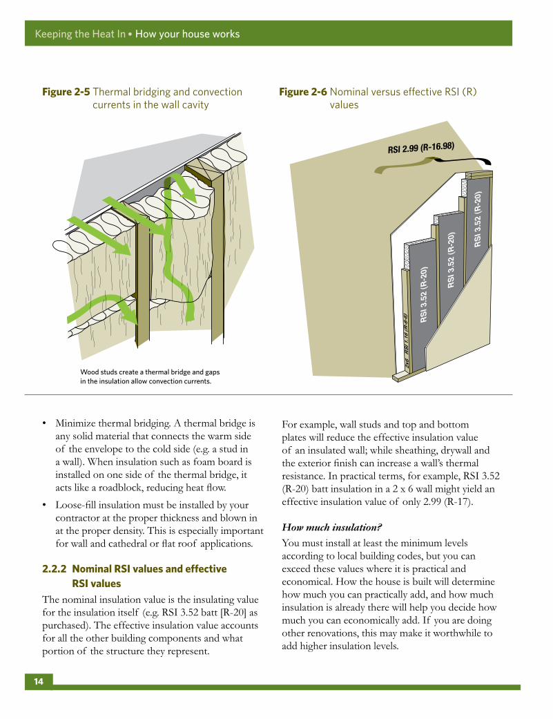
• Minimize thermal bridging. A thermal bridge isany solid material that connects the warm sideof the envelope to the cold side (e.g. a stud ina wall). When insulation such as foam board isinstalled on one side of the thermal bridge, itacts like a roadblock, reducing heat flow.
• Loose-fill insulation must be installed by yourcontractor at the proper thickness and blown inat the proper density. This is especially importantfor wall and cathedral or flat roof applications.
2 .2 .2 NominalRSIvaluesandeffectiveRSIvalues
The nominal insulation value is the insulating value for the insulation itself (e.g. RSI 3.52 batt [R-20] as purchased). The effective insulation value accounts for all the other building components and what portion of the structure they represent.
For example, wall studs and top and bottom plates will reduce the effective insulation value of an insulated wall; while sheathing, drywall and the exterior finish can increase a wall’s thermal resistance. In practical terms, for example, RSI 3.52 (R-20) batt insulation in a 2 x 6 wall might yield an effective insulation value of only 2.99 (R-17).
How much insulation?
You must install at least the minimum levels according to local building codes, but you can exceed these values where it is practical and economical. How the house is built will determine how much you can practically add, and how much insulation is already there will help you decide how much you can economically add. If you are doing other renovations, this may make it worthwhile to add higher insulation levels.
Wood studs create a thermal bridge and gaps in the insulation allow convection currents.
Figure2-5 Thermal bridging and convection currents in the wall cavity
Figure2-6 Nominal versus effective RSI (R) values
Keeping the Heat In ● How your house works
14

2 .3 CONTROLOFAIRFLOW
Controlling airflow protects building materials from moisture damage, improves comfort and makes for a cleaner, healthier, safer and quieter home. Controlling airflow prevents uncontrolled air leakage through the building envelope, provides for fresh air supply and the exhaust of stale air, and provides draft and combustion air for fuel-burning appliances.
2 .3 .1 Airleakagecontrol—weatherbarriers,airbarriersandvapourbarriers
Insulation must trap still air to be effective. Insulation must be protected from wind blowing through from the outside and from air escaping from the inside of the home.
Typically, the air barrier (sometimes referred to as a wind barrier or weather barrier) is under the exterior wall finish or cladding (wood or vinyl siding, brick veneer, stucco, etc.). Its primary roles are to shield the wall components from the weather (rain, wind, etc.) while also providing an escape route to the
Heating degree-days (HDD) are a measure of heating demand based on the difference between the average daily outdoor temperature and 18°C (65°F). Cumulative totals for the month or heating season are used to estimate heating energy needs. Each zone represents an area that experiences a similar number of heating degree-days.
A up to 3500 HDDB 3500–5000 HDDC 5001–6500 HDDD more than 6500 HDD
Figure2-7 Heating degree-day zones
Table2-1 Recommended minimum insulation values
Housecomponent Metric(RSI)orimperial(R)
Nominalinsulatingvalue
ZoneA ZoneB ZoneC ZoneD
WallsRSI 3.9 4.2 4.8 7.1
R 22.0 24.0 27.0 40.0
BasementwallsRSI 3.3 3.3 4.2 4.4
R 19.0 19.0 24.0 25.0
RooforceilingRSI 7.1 8.8 10.6 10.6
R 40.0 50.0 60.0 60.0
Floor(overunheatedspaces)RSI 4.8 5.5 7.1 8.8
R 27.0 31.0 40.0 50.0
Keeping the Heat In ● How your house works
15

exterior for any water vapour that has penetrated the wall cavity. When rain leaks past the cladding or internal water vapour permeates through the air barrier, there should be a space or gap at the base of the wall where the moisture can escape. This space, called the drainage plane, allows moisture to drain down and away.
An air barrier blocks airflow through the building envelope. It reduces heat loss by preventing air from passing in and out through the envelope and protects the insulation and structure from moisture damage. The air barrier, when located on the exterior, may also act as part of the drainage plane. Standard building materials, such as exterior sheathing, building paper and house wrap, act as the air barrier.
The vapour barrier resists the diffusion of water vapour from the inside to the outside of the building envelope. It protects the insulation and structure from moisture damage that can be caused if water vapour moves into and condenses in the envelope assembly. In some applications, the vapour barrier also acts as the air barrier by reducing heat loss as it prevents air from passing in and out through the envelope (i.e. an air and vapour barrier).
A number of building materials resist vapour diffusion well enough to be used as a vapour barrier. These include polyethylene sheeting, smart retarders, oil-based and special vapour barrier paints, some insulation materials, exterior-grade plywood and oriented strand board (OSB).
New houses typically have an air barrier on the outside and a vapour barrier on the inside of the exterior walls. The ceiling typically has only a single air and vapour barrier, as an exterior air barrier is normally impractical due to air sealing constraints caused by the roofing and ceiling structures.
One material can work as both an air barrier and a vapour barrier, provided it meets the requirements of both types of barriers and is properly installed. Polyethylene sheets and foil-backed gypsum drywall can combine these functions. To avoid confusion of terms, when a material is doing both jobs it is called an air and vapour barrier.
Because the house envelope is made up of many components, it is impossible for any one material to surround the house completely and form the air barrier (see Figure 2-9). The air barrier is actually a continuous system made up of many parts that are sealed to each other with caulking, tape, gaskets and weatherstripping. Typical components of the air barrier system include the following:
• polyethylene, drywall or plaster – when used forlarge interior surfaces such as walls and ceilings
Figure2-8 Weather barrier, air barrier and vapour barrier
Weather and air barrier
Weather barrier
Vapour barrier
Vapour and air barrier
OR
A) Exterior air barrier B) Interior air barrier
Keeping the Heat In ● How your house works
16

• windows, doors, hatches, vent dampers andany components that close an opening inthe envelope
• structural parts of the building in some cases,such as the sill plate or rim joist
2 .3 .2 Howtightshouldanairbarriersystembe?
The air barrier must be continuous and well sealed. But if the air barrier is too tight, how will fresh air get into the house?
First, most older houses are so loosely built that, even after extensive air-leakage control work, enough air will still come in to provide ventilation. Second, the air barrier is just the first step in the control of airflow.
The other essential steps include providing air for ventilation and air for combustion in a controlled manner. These steps may be necessary in houses where extensive retrofit work has already been done.
Read Chapter 9, “Operating your house,” for essential information about ensuring proper ventilation and adequate combustion air for your home.
2 .4 CONTROLOFMOISTUREFLOW
Control of moisture in all its forms is critical in making homes durable and comfortable. Building components and practices such as flashings, roofing and waterproofing the basement protect the home from liquid water. It is equally important to control the movement of water vapour to provide added protection for the house structure and help maintain indoor humidity at a comfortable level.
Controlling moisture involves construction techniques that keep moisture away from the structure, producing less moisture and exhausting the excess.
Figure2-9 The air barrier is a system that joins several building components
Circle-dotted line = air barrierDashed line = vapour barrierCircle and dashed line = air and vapour barrier
SAFETYWARNING:Every home that has a combustion appliance should have carbon monoxide detectors. The local building code may require it. Typically, the requirement is to have one detector located near the furnace or appliance and one detector in each bedroom area.
Keeping the Heat In ● How your house works
17

2 .4 .1 SourcesofmoistureinthehomeEven houses that are apparently dry, with no leaks in the basement or roof, can have moisture problems. Where does all the moisture come from?
A family of four generates about 50 litres (L) (17 gallons) of water a week through normal household activities. Where basement waterproofing is inadequate, groundwater in the soil can migrate through the foundation by capillary action and evaporate on the surface of the wall or floor. A small plumbing leak can produce a lot of moisture. Finally, during humid weather, building materials and furnishings absorb moisture from the air and then expel it during the heating season.
Despite all this water produced each day, most older and even newer, poorly air sealed houses have dry air in winter to the point that they have to have humidifiers installed. Why?
Cold outdoor air cannot carry much water vapour. In poorly air sealed homes, uncontrolled airflow brings colder, drier air indoors and forces the warm, moist air out through openings in the upper walls and attic. The moist air condenses and causes mould and structural damage.
When insulation is added, the building exterior becomes much colder. Unless there is additional protection, such as an air and vapour barrier, water can condense in parts of the building structure, for example, in the insulation.
As the warm, moist air cools in the cold outer layers of the building, the water vapour it holds may condense as liquid or, if it is cold enough, as frost. This can reduce the effectiveness of insulation and even cause rot, peeling paint, buckled siding, mould growth and other problems.
Table2-2 Moisture added to the house through various household activities (for a family of four)
Activity Moistureproduced
(L)
Cooking – three meals daily for one week
6.3
Bathing – 0.2 L per shower or 0.05 L per bath
2.4
Clothes washing (per week) 1.8
Floor mopping per 9.3 m2 (100 sq. ft.) 1.3
Normal respiration and skin evaporation from occupants
38.0
Totalmoistureproductionperweek 49 .8
2 .4 .2 Howmuchhumidity?Humidity levels above 20 percent help prevent dry, sore throats and should make the air feel warmer and more comfortable. Moist air will also eliminate static electricity in the house and help to protect plants and preserve your furniture.
On the other hand, humidity levels above 40 percent can cause frosting and fogging of windows, staining of walls and ceilings, peeling paint, mould growth and odours. When relative humidity is more than 50 percent, airborne diseases become more difficult to control.
Condensation on windows or static electricity can provide good indications of the relative humidity levels. However, a humidity sensor or humidistat can monitor or adjust humidity levels more accurately.
Keeping the Heat In ● How your house works
18

2 .4 .3 KeepingthestructuredryHere are four strategies that are used to keep the structure dry:
• Exterior weather and moisture protection:This strategy requires building paper, siding,flashing, gutters and other constructiontechniques (e.g. a drainage plane) to shed waterand repel wind-driven rain. It also involvesbelow-grade measures such as proper drainage,grade slope and water proofing to protect thefoundation from groundwater leaks or frommoisture movement by capillary action.
• Reducing moisture at the source: Thisinvolves producing less moisture in the firstplace, exhausting moist air and bringing in drierair. (For solutions to moisture problems, seeChapter 9, “Operating your house.”)
• Preventing moist indoor air from getting intothe envelope: This requires a vapour barrierto reduce moisture movement by diffusion andan air barrier to prevent moisture movement byair leakage.
As a general rule, the vapour barrier should beon the warm side of the insulation. In somecases, however, the vapour barrier can be locatedwithin the wall or ceiling assembly, following theone-third, two-thirds rule (1/3 – 2/3 rule). This rulerequires that at least two thirds of the insulationvalue of the wall is on the cold side of the vapourbarrier (see Figure 2-12). Because this ratio shouldbe adjusted for houses with high interior humidity
Figure2-10 Water vapour condenses into liquid water or frost when it reaches the dew point
Figure2-11 The building envelope must shed water from the roof to the footings
Keeping the Heat In ● How your house works
19

(i.e. levels exceeding 50 percent, such as those with indoor pools or open spa-pools) or for homes in extremely cold climates (i.e. northern Canada), consult with your local building authority.
• Letting the envelope dry (through) to theoutside: This final strategy allows the house todeal with seasonal fluctuations in humidity andto release any moisture that does penetrate theenvelope from the interior or exterior. Dryingto the outside is promoted by layering materialsmost resistant to vapour diffusion on the warmside of the envelope and the least resistant (suchas building paper) on the outside.
Some wall systems work well with a relatively impermeable insulated sheathing because the interior wall-cavity temperatures are kept high. As a precaution, when retrofitting a wall, always install code-compliant RSI levels of insulated sheathing and ensure that the interior surfaces are vapour resistant.
Some siding applications have an air space or drainage plane immediately behind the exterior finish to promote drying out of materials that have been soaked by rain, wind or solar-driven dampness. This drainage plane also provides an escape route for any moisture that has penetrated the wall cavity from the indoors. If installing insulated siding, keep a drainage space behind the insulation even though a small amount of the insulation value of the siding will be lost.
2 .5 OLDERHOMES
Older homes are part of our architectural heritage and require special consideration when retrofitting. Maintaining the durability of the structure is especially important. Some houses that were built before 1950 incorporated unusual construction details and materials that make it necessary to improvise and adapt standard retrofit methods.
Remain sensitive to the heritage aspect, design, materials and particular features of the house when retrofitting. Some houses may even have special heritage designation that may limit what can be changed. The retrofit will need to minimize changes to the building’s appearance and emphasize repair, rather than replacement, of building components. In any event, it is advisable to consult with your local building authorities about planned upgrades.
In some cases, you may want to consult with an architect or a building conservator with knowledge of heritage house conservation and in others, an engineer, before undertaking work that may compromise the structure.
Figure2-12 Up to one third of the insulating value can be installed on the warm side of the vapour barrier
2/3
1/3
Keeping the Heat In ● How your house works
20

Keeping the Heat In
3 Materials
3 .1 Insulation
3 .2Insulationvaluestable
3 .3Airbarriermaterials
3 .4Vapourbarriermaterials
MATERIALS
Choosing the right materials and installing them properly ensures the finished job lives up to your expectations. This chapter describes insulation, air barrier and vapour barrier materials.
3 .1 INSULATION
To be effective, insulation must resist heat flow, fill the space completely and evenly, be durable, and for some locations, withstand exposure to heat or moisture. Different materials may be used at different locations in the house envelope depending on the space available, ease of access and other installation requirements.
In addition, consider the following:
• Is the material available locally?
• Is it relatively easy to install, especially for do-it-yourselfers?
• Is it the best buy for the space available ( eitherhigh insulating value per dollar if you have alot of open space, or high insulating value perthickness if space is restricted)?
• Can it conform to surface irregularities?
21

• Is it rigid enough to provide support for finishedmaterials or resist pressures against its surfaces?
• Does any single type of insulation requiremore accessory products than another (e.g. fireprotection, air and vapour barrier or framing)?
For proper application, material handling, safety equipment and protective clothing requirements, follow the manufacturer’s instructions (see Section 1.4, Health and safety considerations).
3 .1 .1 DoyourresearchOnce you have selected a product, get the facts about it and find out about proper installation techniques. Compare the advantages, limitations and intended use of different products.
Materials (or their packaging) may be marked indicating that they comply with Canadian product standards. If they do not, they may have an evaluation number issued by the Canadian Construction Materials Centre. Your local municipal office can tell you if certain products are acceptable for use in your municipality.
Manufacturers, suppliers and contractors should be able to provide you with information about products. They should also be able to advise you on any health and safety issues (such as indoor air quality and fire safety) and what they will do to reduce these risks.
Ask for a Material Safety Data Sheet (MSDS) that lists the hazardous ingredients, safety information and emergency measures related to specific products. An MSDS is required for certain industrial and chemical products used in the workplace like paint, caulking, spray foam insulation and cleaners. An MSDS is not required for manufactured items (e.g. insulation) or consumer products, but it may be available from the manufacturer or supplier.
Manufacturers and suppliers are responsible for making sure that the products they sell comply with
Canadian legislation. If you are concerned about the safety of a particular product, find out if it is prohibited or regulated under the Hazardous Products Act (the Act), other relevant federal, provincial or territorial legislation, or municipal bylaws.
For example, as of the date of publication, one type of insulation product is prohibited and two others are regulated under the Act.
Prohibited
• Urea formaldehyde-based foam insulation(UFFI) foamed in place (prohibited in Canadain 1980): This includes insulation productsthat are available in the United States that areurea-formaldehyde based and are installed via afoaming process.
Regulated
• Cellulose fibre insulation (regulated inCanada in 1979): This commonly used andeffective insulation material must meetcertain performance standards with respect toflammability, among other things.
• Asbestos: A product composed entirely ofasbestos cannot be sold as a consumer product.Asbestos products applied by spraying musthave asbestos fibres coated with a binder duringspraying and cannot come loose after drying.
For more information about the Act and for clarification on these requirements, contact Health Canada’s Consumer Product Safety Office. Visit the Planning energy efficiency renovations for your home section of our website for more information.
3 .1 .2 CostofmaterialsGenerally, the cost per RSI value is lower for loose fill or batt type materials than for rigid board or foam type insulations. However, the price of the basic material is just one aspect. High
Keeping the Heat In ● Materials
22

material costs may be offset by lower installation costs or the installer’s preference for a particular insulation technique.
3 .1 .3 Thermalperformance:Howeffectiveisthatmaterial?
Thermal resistance values (RSI and R) are listed in Table 3-1. This table also provides average design specifications because values for different manufacturer’s products of the same class may vary.
3 .1 .4 Ifitsoundstoogoodtobetrue . . .Some manufacturers may claim that an insulation product offers remarkable insulating value. Any product that is promoted as offering a long-term thermal resistance exceeding RSI 1.14/25 mm (R-6.5/in.) may be making a claim that is not
substantiated by industry-recognized tests to specific accepted standards. Also, be alert to any manufacturer’s thermal performance claims that are based on building envelope systems (e.g. whole wall or ceiling configurations) that are not identical to those configurations or conditions in which the product is being considered for use.
3 .1 .5 SummaryofinsulationtypesThis section explains the following insulation types:
• batt or blanket
• loose fill
– cellulose fibre
– glass fibre
– mineral fibre (mineral wool or rock wool)
Figure3-1 Insulating materials and safety gear
Keeping the Heat In ● Materials
23

• rigid board
– expanded polystyrene
– extruded polystyrene
– mineral fibre rigid board
– polyurethane and polyisocyanurate boards
• spray foam
– closed-cell polyurethane foam
– open-cell polyurethane foam
• cementitious foam
• reflective bubble foil insulations and radiant barriers
Batt or blanket insulation
Glass fibre and mineral fibre (slag or rock wool) batt or blanket insulation is relatively easy to install in accessible spaces such as exposed wall cavities and some attics. This type of insulation does not settle, it conforms to slight surface irregularities, and it can be cut to fit. To gain the maximum insulating benefit, batts and blankets should completely fill the space they are fitted into and neither be compressed nor have gaps (especially avoid compressing the edges).
Some products are available in non-combustible form. Check with the manufacturer to verify that the products are non-combustible. Safety equipment and protective clothing are required during installation.
Loose-fill insulation
Loose-fill insulation is suitable for walls and floors and excellent in attics and enclosed spaces, such as roofs, where the space between the joists may be irregular or cluttered with obstacles. You can use it to top up existing insulation in attics and accessible enclosed wall cavities and to fill in cracks and small or uneven spaces. It is not appropriate for below-grade application. Use safety equipment and wear protective clothing during installation.
Loose-fill insulation may be poured or blown into cavities. Pouring will generally require more material than blowing to achieve a specified RSI value. Check the manufacturer’s information on the quantity of material required to provide a specified RSI value.
Most loose-fill materials installed in walls will settle after installation, creating gaps at the top of the cavities. There are different installation approaches for each type of material to lessen this effect.
Loose-fill insulation options include cellulose fibre, glass fibre and mineral fibre described as follows.
i) Cellulose fibre
Cellulose fibre is made from shredded newsprint treated with chemicals that resist fire and fungal growth and inhibit corrosion. Because of its small particle size, it can fill any gaps around obstructions such as nails or electrical wires that are within cavities. However, blowing cellulose fibre can create a lot of dust. Be sure to make allowance for settling.
SAFETYWARNING:Never allow insulation materials to come into contact with a chimney or a combustion vent, an exposed recessed lighting fixture or old knob and tube wiring because these can pose a fire hazard. See Section 1.4, Health and safety considerations.
TECHNICALNOTE:Glass and mineral fibre insulations are typically poor air sealing products. Sometimes these products are stuffed into cracks and gaps (at the header in the basement or around a window) in an attempt to block air leakage. This practice is not effective. Always air seal by using appropriate materials and techniques.
Keeping the Heat In ● Materials
24

Cellulose fibre offers limited additional air sealing when blown into cavities that already have insulation. However, it will provide increased air sealing when blown into empty and restricted cavities at dense-pack levels, typically around 56 kilograms per cubic metre (kg/m3) (3.5 pounds per cubic foot [lb./cu. ft.]).
To reduce settling, some companies offer a wet-spray installation technique for their products for open wall cavities that may require a fabric net. Drying time varies for the different types and brands of product. A trained and manufacturer-licensed technician typically performs the installation.
ii) Glass fibre
Loose-fill glass fibre is a similar material to glass fibre batts, but chopped up for blowing or pouring applications. Hand-poured glass fibre works best in open horizontal surfaces such as attics. Blown glass fibre can be used in both horizontal and vertical applications.
At conventional application pressure, it may be difficult to install in cavities that are partially blocked by nails, framing, electrical wiring, etc. At dense-pack levels (i.e. around 40 kg/m3 [2.5 lb./cu. ft.]), higher RSI (R) values are achieved and can better fill cavities that have restrictions. For walls, application density is usually two to two-and-a-half times the manufacturer’s recommended rate of application for horizontal surfaces. This higher density ensures better overall application and performance.
Some products are classified as non-combustible. Check the manufacturer’s specifications for verification.
iii) Mineral fibre (mineral wool or rock wool)
Mineral fibre is treated with oil and binders to suppress dust, maintain shape and ease the blowing process. It is similar to glass fibre in appearance and texture. Mineral fibre is suitable for accessible attics and inaccessible areas such as wood-frame walls,
roofs or floors. For walls, the density of application is usually two to two-and-a-half times the manufacturer’s recommended rate of application for horizontal surfaces.
Mineral fibre may be acceptable for insulating around masonry chimneys as it will not support combustion. However, check with your local building inspector to learn what is accepted.
Rigid board insulation
Rigid board insulation (insulating boards) is currently manufactured from mineral fibre or foam plastic materials. These materials have a high insulating value per unit thickness although the cost per RSI value is greater than that for loose-fill or batt or blanket insulations.
Insulating boards are lightweight and easy to cut and handle. Fitting them into irregular spaces, however, can be a tedious process. Some boards are available with special coverings (e.g. a fire-resistant material) and their own system of attachment. Some board materials can be ordered pre-cut to specific sizes for an additional cost.
When installed on interior surfaces, all plastic-based rigid board insulation must be covered with a fire-resistant material – typically 13-mm (1/2-in.) drywall – that is mechanically fastened to the building structure. Plastic boards must be protected from prolonged exposure to sunlight, solvents and some sealants. Be sure to ask your supplier for a compatible sealant.
Rigid board insulation options include expanded polystyrene, extruded polystyrene, mineral fibre rigid board and polyurethane and polyisocyanurate plastic boards described as follows.
i) Expanded polystyrene
Expanded polystyrene (EPS), often called bead board, is made by using pressurized steam to expand and form polystyrene beads into rigid foam plastic boards. High and low-density products are
Keeping the Heat In ● Materials
25

manufactured using steam as the blowing agent. High-density board is more moisture resistant and can be used on the exterior of foundation walls in dry, sandy soils.
ii) Extruded polystyrene
Extruded polystyrene (XPS) is a foam plastic board with fine, closed cells containing a mixture of air and non-ozone depleting refrigerant gases (fluorocarbons). If joints are sealed properly, it can perform as an air barrier and, at certain thicknesses, may perform as a vapour barrier. Low permeability means that it does not absorb or pass on moisture, making it suitable for below-grade applications.
iii) Mineral fibre rigid board
Mineral fibre insulation, when compressed and held together with a combustible binder, forms semi-rigid board stock. The fibres are aligned vertically so that any water that penetrates the surface will run down, making it suitable as a drainage layer. High-density, semi-rigid mineral fibre board for residential use is designed for below-grade exterior applications.
iv) Polyurethane and polyisocyanurate boards
Polyurethane and polyisocyanurate plastic boards are made of closed cells containing non-ozone depleting refrigerant gases (fluorocarbons) instead of air. They usually come double-faced with foil or are sometimes bonded with an interior or exterior finishing material. These products must be protected from prolonged exposure to sunlight and water. If the seams are well sealed, they can act as an air and vapour barrier. Use is generally limited to areas where a high RSI is desired and space is limited.
Spray-foam insulation
Spray-foam insulation is made of plastic resin (e.g. soy-based resins or resins made from recycled plastic) and a catalyst, which is prepared and applied on the job site. Spray kits for this type of insulation are available to the consumer, but employing a certified installer who is trained in the application
of the specific product will ensure the best results. The liquid foam is sprayed directly onto the building surface or poured into enclosed cavities with a pump-driven applicator. The foam expands in place and sets in seconds.
There are two types of foam: low density and high density. When installed on interior surfaces, all plastic-based foam insulation must be covered with a fire-resistant material – typically 13-mm (1/2-in.) drywall – that is mechanically fastened to the building. All foam plastics must be protected from prolonged exposure to sunlight.
Options for spray-foam insulation include closed-cell polyurethane foam and open-cell polyurethane foam described as follows.
i) Closed-cell polyurethane foam
Closed-cell polyurethane foam (also called high-density or two-pound foam) is sprayed onto surfaces in layers not more than 50 mm (2 in.) thick at each pass (if greater thicknesses are desired), where it hardens in seconds. A 24-hr curing and off-gassing period is required before occupancy can resume. The foam can expand 28 to 35 times its initial volume and should not be used in enclosed cavities.
This product can be used as an air barrier. When applied to a thickness of 50 mm (2 in.), it can sometimes act as a vapour barrier. It can be used below grade and it bonds well to clean cement and masonry where it also makes a good moisture barrier. Though high-density foam is a premium,
TECHNICALNOTE:The RSI (R) value listed in Table 3-1 may be lower than that quoted by the vendor because it takes into account the loss of the blowing gases over time and the recent changes that ban the use of ozone-depleting blowing agents.
Keeping the Heat In ● Materials
26

hard textured, multi-task product, it is not generally used to completely fill cavities due to its high cost.
ii) Open-cell polyurethane foam
Open-cell polyurethane foam (also known as low-density or half-pound foam) is made from a combination of isocyanurate resins and catalysts, resulting in an open-celled, spongy semiflexible material. With a very high expansion rate – up to 100 times its initial volume – and its lower comparative cost, this product is more effective than closed-cell foam for filling larger cavities. It can be used as an air barrier but not a vapour barrier.
Cementitious foam insulation
Recently introduced into Canada, cementitious foam insulation is a non-plastic based non-combustible
material with a soft chalky texture. When poured or injected into cavities by a trained installer, it has the consistency of shaving cream and may require some drying out time. This insulation can be used as an air barrier but not a vapour barrier.
Reflective bubble foil insulations and radiant barriers
Reflective bubble foil insulation is essentially a plastic bubble wrap sheet with a reflective foil layer and belongs to a class of insulation products known as radiant foils. Reflective bubble foil insulations – and other radiant barrier products like paints and sheeting – are noted for their ability to reflect unwanted solar radiation in hot climates, when applied properly.
However, all of Canada is considered a cold climate, so these products do not perform as promoted. Though they are often marketed as offering very high insulating values, there is no specific standard for radiant insulation products, so be wary of posted testimonials and manufacturers’ thermal performance claims.
Research has shown that the insulation value of reflective bubble foil insulations and radiant barriers can vary from RSI 0 (R-0) to RSI 0.62 (R-3.5) per thickness of material. The effective insulating value depends on the number of adjacent dead air spaces, layers of foil and where they are installed.
If the foil is laminated to rigid foam insulation, the total insulating value is obtained by adding the RSI of the foam insulation to the RSI of the dead air space and the foil. If there is no air space or clear bubble layer, the RSI value of the film is zero.
3 .2 INSULATIONVALUESTABLE
This table lists the thermal resistance ranges and the accepted design specification values or averages of insulation materials, including older and less common materials that you may find in a house.
Spacer
Radiant heat
FinishAir gap
Figure3-2 Foil-faced foam board acts as an air and vapour barrier
Keeping the Heat In ● Materials
27

Table3-1 Insulation values
Material RangesRSI/25 .4mm(R/in .)
DesignspecoraverageRSI/25 .4mm(R/in .)
Polyurethane closed-cell spray foam 0.97 to 1.14 (R-5.5 to 6.5) 1.06 (R-6)
Polyurethane board 0.97 to 1.2 (R-5.5 to 6.8) 1.06 (R-6)
Extruded polystyrene board (XPS) 0.88 (R-5) 0.88 (R-5)
Polyisocyanurate spray foam 0.85 to 1.46 (R-4.8 to 8.3) 0.88 (R-5)
High-density glass fibre board 0.63 to 0.88 (R-3.6 to 5) 0.7 (R-4)
Expanded polystyrene board – Type I (EPS) 0.67 (R-3.8) 0.67 (R-3.8)
Expanded polystyrene board – Type Il (EPS) 0.7 to 0.77 (R-4 to 4.4) 0.7 (R-4)
Glass fibre roof board 0.67 (R-3.8) 0.67 (R-3.8)
Cementitious foam 0.69 (R-3.9) 0.69 (R-3.9)
Cotton fibre batt 0.67 (R-3.8) 0.67 (R-3.8)
Cork 0.65 to 0.67 (R-3.7 to 3.8) 0.65 (R-3.7)
Polyurethane open-cell spray foam 0.63 to 0.67 (R-3.6 to 3.8) 0.63 (R-3.6)
Polyurethane open-cell foam, poured 0.7 (R-4) 0.7 (R-4)
Cellulose fibre, wet sprayed 0.53 to 0.67 (R-3 to 3.8) 0.63 (R-3.6)
Cellulose fibre, blown, settled thickness 0.53 to 0.67 (R-3 to 3.8) 0.63 (R-3.6)
Mineral fibre batt 0.53 to 0.7 (R-3 to 4) 0.6 (R-3.4)
Wood fibre 0.58 (R-3.3) 0.58 (R-3.3)
Mineral fibre, loose fill, poured 0.44 to 0.65 (R-2.5 to 3.7) 0.58 (R-3.3)
Glass fibre batt 0.55 to 0.76 (R-3.1 to 4.3) 0.56 (R-3.2)
Glass fibre, loose fill, poured 0.39 to 0.65 (R-2.2 to 3.7) 0.53 (R-3)
Mineral fibre, loose fill, blown 0.51 to 0.56 (R-3 to 3.8) 0.53 (R-3)
Glass fibre, loose fill, blown 0.48 to 0.63 (R-2.7 to 3.6) 0.51 (R-2.9)
Fibreboard (beaverboard) 0.41 (R-2.3) 0.41 (R-2.3)
Mineral aggregate board (Insulbrick) 0.41 to 0.7 (R-2.3 to 4) 0.46 (R-2.6)
Wood shavings 0.18 to 0.53 (R-1 to 3) 0.42 (R-2.4)
Vermiculite* 0.37 to 0.41 (R-2.1 to 2.3) 0.38 (R-2.2)
Compressed straw board 0.35 (R-2.0) 0.35 (R-2.0)
Keeping the Heat In ● Materials
28

3 .3 AIRBARRIERMATERIALS
The main purpose of an air barrier system is to protect the building structure and the insulation from moisture damage. It must resist air movement; be continuous, completely surrounding the envelope of the house; be properly supported by rigid surfaces on both the interior and exterior (to prevent movement in high winds); and be strong and durable. Attention to detail during installation is critical for good performance.
Various materials throughout the envelope act as an air barrier. Large-surface building materials such as drywall, baseboards or structural members and windows and doorframes are incorporated into the air barrier by sealing them to the adjoining materials. Caulking, tapes and gaskets are used for joints between materials that do not move, and weatherstripping, for joints that do move.
3 .3 .1 ChoosinganairbarriermaterialIf the material that you are considering using offers resistance to airflow and is strong and durable, consider the following installation factors:
• Is it easy to install without help?
• If installed in a concealed location, will it last the life of the building or will it be accessible and easily repairable?
• Is it compatible with other materials in the system? Can it be successfully sealed to adjacent materials?
• Is the choice of material appropriate for any other work being done?
• Does it serve other functions such as acting as insulation, a vapour barrier or part of a drainage plane?
Sheet materials
i) House wrap (typically made from a spun polyolefin plastic)
• is generally used to wrap the exterior of a house
• acts as a wind barrier when installed on the exterior; prevents wind from reducing the nominal RSI value of insulation
• acts solely as an air barrier; does not function as a vapour barrier
• can function as a drainage plane surface when the upper sheet overlaps the lower sheet and the flashings and all edges and penetrations are sealed with acoustical sealant or sheathing tape
• application in wide sheets minimizes the number of seams required
• should be protected from extended exposure to sunlight
Material RangesRSI/25 .4mm(R/in .)
DesignspecoraverageRSI/25 .4mm(R/in .)
Eel grass (seaweed) batt 0.53 (R-3) 0.53 (R-3)
Cedar logs 0.18 (R-1) 0.18 (R-1)
Softwood logs (other than cedar) 0.18 to 0.25 (R-1 to 1.4) 0.22 (R-1.25)
Hardwood logs 0.12 (R-0.7) 0.22 (R-1.25)
Straw bale 0.23 to 0.28 (R-1.3 to 1.6) 0.26 (R-1.45)
Radiant foil insulation See Radiant foils
*See the vermiculite health and safety warning in Section 1.4, Health and safety considerations.
Keeping the Heat In ● Materials
29

• when installed with stucco or embedded in stone veneers, requires an additional 5-mm (3/8-in.) gap for a drainage plane (use a drainage mat) to prevent the stucco from bonding to the house wrap
• should not come in direct contact with cedar because the oils in the wood can cause deterioration in the product
ii) Polyethylene sheeting
• is commonly installed as a vapour barrier in the thickness of 0.15 mm (6 mil) because it is more durable on the construction site
• should be labelled showing that it conforms to the Canadian General Standards Board (CGSB) standard for polyethylene
• application in wide sheets minimizes the number of seams required
• should have the seams and edges supported on both sides to maintain the seal
• requires an appropriate sealant and overlapped joints
• functions as a vapour barrier. Should always be used on the interior or follow the 1/3 – 2/3 rule (see Section 1.4, Health and safety considerations). Follow local building codes for placement of a polyethylene vapour barrier.
iii) Polyamide sheeting
• is also known as Nylon-6 vapour retarder film or smart barrier
• adapts its permeability to the conditions. In cold temperatures, it offers high resistance to vapour pressure; in warmer conditions, it becomes more permeable, allowing the structure to dry out.
• can be installed as a vapour barrier or an air barrier
• should not be used in indoor areas that have high humidity such as an indoor spa or pool or a bathroom
iv) Rigid materials
Most solid building components including drywall, plaster, plywood, glass, wood, rigid foam insulation and poured concrete (not concrete blocks) will act as air barriers. Seal all seams between these materials with the appropriate caulking, weatherstripping, tape or gasket. For example, caulking can be used between the baseboard and a wall as well as between the baseboard and the floor, linking the air sealing qualities of three building components.
3 .3 .2 SealantsCaulking seals joints between building components. Most joints move because of changes in moisture and temperature in the building. Some materials can seal a larger joint and accommodate more joint movement than others. Choose carefully because there is wide variation among the same type of products produced under different brands. If possible, always select the premium product for long-term durability. Choosing the proper product and paying attention to the quality of application are crucial.
All sealants will require extra ventilation of the house after application to let the material cure. Typical curing time will be two or three days for interior applications. For application directions, see Section 4.2, Caulking and other air sealing materials.
Materials labelled “for exterior use only” may not be suitable for indoor applications because they may contain volatiles that may be hazardous if inhaled in a confined space over an extended period. Read the manufacturer’s literature carefully.
TECHNICALNOTE:If the sheeting will be exposed to sunlight over an extended period during renovations, use a UV-stabilized polyethylene.
Keeping the Heat In ● Materials
30

The following factors limit the effectiveness of caulking:
• the flexibility and elasticity of the product. Some products can span a larger gap than others. Use a backer rod or foam rope in joints of 6 mm (1/4 in.) and larger before applying caulking to ensure an effective seal.
• its compatibility with the materials being joined. Read the manufacturer’s literature carefully.
• its durability, paintability and curing time. If the product will be exposed to sunlight, make sure it is appropriate for this condition.
• its ease of removal and reapplication. Some products can be used over previous applications while others cannot; some clean up easily with water, some require solvents, and some are very difficult to remove once cured.
Table 3-2 lists caulks and sealants available at most building supply stores. It is designed to help you select the best product for each application. If possible, always select a premium product for long-term durability.
TECHNICALNOTE:Be mindful when using caulks and sealants. Urethane foams are impossible to remove once cured, other products are flammable. Read manufacturers’ literature and take proper precautions during installations (wear gloves, etc.).
Table3-2 Air barrier caulking and sealants
Type Bondsto Application Maximumjoint Comments
Acoustical sealant • metal, concrete, gypsum board and polyethylene
• use only where sandwiched between two materials (not exposed to the exterior)
• staples required when sealing joints in polyethylene
• can be reapplied over itself
• 16 mm (5/8 in.)• accepts 10% joint
movement
• good durability: 20 years
• non-hardening• not paintable
Butyl rubber caulk (synthetic rubber sealant)
• most surfaces but particularly suited to metal and masonry
• generally used on exterior
• ventilation required during application and curing (up to three days)
• difficult to smooth
• 13 mm (1/2 in.)• accepts 5 to 10%
joint movement
• low to moderate durability: 5 to 10 years
• available in a variety of colours
• paintable after curing
Keeping the Heat In ● Materials
31

Type Bondsto Application Maximumjoint Comments
Silicone sealant caulk
• most non-porous surfaces
• primers may be required on wood, steel or anodized aluminum
• cannot be used over existing silicone
• interior and exterior grades
• ventilation required during application
• easy to smooth• flexible, watertight
seal when cured
• 25 mm (1 in.) with backer rod
• accepts 12 to 50% joint movement
• excellent for large moving joints
• good durability: 20+ years
• available with fungicide for wet locations and in a high-temperature type for use around chimneys/vents
• available in colours and clear
• most types not paintable
• paintable types less durable
Polysulphide caulk (synthetic rubber sealant)
• stone, masonry and concrete surfaces when used with a special primer
• may attack some plastics
• generally used on exterior
• can be used below grade
• ventilation required while curing
• moderately easy to smooth
• flexible upon curing
• 25 mm (1 in.) with backer rod
• accepts 12 to 25% joint movement
• very good durability: 25+ years
• available in several colours
• paintable
Polyurethane caulk (urethane)
• most surfaces• preferred choice of
window and door installers
• exterior use only• ventilation
required while curing
• long curing time• can be hard to
smooth• flexible upon
curing• can be reapplied
over itself
• 25 mm (1 in.) with backer rod
• very stretchable: up to 50% joint movement
• very good durability: 25+ years
• limited colours• paintable
Acrylic latex caulk • most surfaces • interior and exterior use
• ventilation required when curing
• easy to smooth
• 10 mm (3/8 in.)• accepts 7 to 10%
joint movement
• low to moderate durability (varies by brand): 5 to 25 years
• water cleanup• comes in colours• paintable
Keeping the Heat In ● Materials
32

Type Bondsto Application Maximumjoint Comments
Acrylic latex with silicone caulk
• most surfaces • interior and exterior use
• ventilation required when curing
• easy to smooth• can be reapplied
over itself
• 13 mm (1/2 in.) • accepts 10 to 15%
joint movement
• very good durability: 30+ years
• water cleanup• paintable
Elastomeric latex sealant
• most surfaces • interior (some brands only) and exterior use
• ventilation required when curing
• flexible upon curing
• moderately easy to smooth
• can be reapplied over itself
• 25 mm (1 in.) with backer rod
• accepts 50% joint movement
• very good durability: 30+ years
• water cleanup limited colours
• paintable
Urethane foam sealant (low, medium and high expansion types)
• most surfaces except Teflon, polyethylene or silicone plastics
• interior and exterior use
• use only low expansion type around window and doorframes or risk bowing
• can be used below grade
• ventilation required during installation
• can be reapplied over previous foam
• protect from sunlight
• check the can for expansion rates and sizes of cracks that can be filled
• very good for filling larger joints and cavities like header/joist intersections, around indoor and outdoor plumbing and vent openings, and wiring holes
• good durability: 10 to 20 years
• available in individual aerosol spray cans and dispensing systems with spray nozzles
• hard consistency when cured
• use gloves and a drop cloth: impossible to remove residue after curing
• use acetone to clean up uncured foam
• paintable
Keeping the Heat In ● Materials
33

Type Bondsto Application Maximumjoint Comments
Latex foam sealant • most surfaces • interior and exterior use
• must be covered for exterior use due to open-cell structure
• not for use below grade
• ventilation required during installation
• extremely flammable during application: read precautions on the product label
• can be applied in successive layers
• difficult to smooth
• will not over expand – reaches 75% of size upon application
• recommended around window and door frames, but requires a vapour barrier
• good durability: 10 to 20 years
• cleans up with water
• soft, spongy consistency when cured
• paintable
High-temperature stove or muffler cements and non-combustible sealants
• most materials• typically used in
conjunction with other materials for sealing around masonry or factory-built chimneys
• interior and exterior use
• for use in high temperature applications
• easy to smooth
• no joint movement • very good durability
• compatible with high-temperature silicone sealant
• check product for CSA or UL rating for high-temperature use
• available at heating equipment supply stores
Keeping the Heat In ● Materials
34

3 .3 .3 GasketsGaskets are used to seal joints where caulking may not be appropriate. Table 3-3 describes the most common types of gasket materials and where each type works best.
Table3-3 Gaskets
Type Application Installation Comments
Sill plate gasket (polyethylene foam strips)
• installed between the foundation and sill plate during construction or where existing house walls meet
• staple to hold it temporarily in place
• cuts easily with a knife
• available in 152 and 203 mm (6 and 8 in.) widths on 24 m (79 ft.) rolls
Foam backer rod (closed-cell compressible foam rope)
• excellent for filling gaps before caulking
• ensure caulking will fill the gap (see product specifications for maximum joint width)
• available in diameters of 6 to 50 mm (1/4 to 2 in.)
Electrical outlet and lighting fixture gaskets (pre-cut)
• designed to fit behind the cover plates of electrical receptacles, switches and lighting mounts
• electrical outlet gaskets are more effective when caulked and should be used in conjunction with child-safety plugs to reduce air leakage through electrical sockets
• place the centre cut-out piece of foam gasket over the end of the electrical plug or child safety plug to ensure a proper seal
Neoprene and elastomeric gaskets
• excellent for sealing joints and penetrations where movement is to be expected such as plumbing stacks
• best slipped over piping, if possible
• very difficult to seal if it must be cut to fit around piping
• flexible and very durable
Figure3-3 Electrical outlet gasket Figure3-4 Foam backer rod
Keeping the Heat In ● Materials
35

Figure3-5 Types of weatherstripping
Closed-cell foam
Spring vinyl
Door sweep
Ribbed
Spring metal
Full threshold
Tubular
Magnetic strip
Spring loaded
3 .3 .4 WeatherstrippingWeatherstripping is used to block air leakage around doors and the operable parts of windows. Weatherstripping comes in a variety of shapes: flat strip, tube or V (i.e. V-strips), and can be designed to work under compression or by sliding along the joint. To be effective, the product must close the gap and not allow air to pass. Some products get hard – and less effective – in cold weather when you need them the most.
When choosing weatherstripping, consider the size of the gap to be sealed and the durability, ease of installation and finished appearance of the product. Look for products that are flexible and that spring back to their original shape quickly and easily. Avoid products that make it difficult to operate the window or door. When replacing weatherstripping, bring a sample of the old material to the store with you to ensure that you purchase the correct product.
Keeping the Heat In ● Materials
36

A wide range of products is available in most building supply stores, including complete sealing kits. For the best quality weatherstripping, contact window and door manufacturers or installers.
Table 3-4 lists the major types of products.
Table3-4 Weatherstripping
Compression strips
Category Application Installation Comments
Closed-cell foam (with or without vinyl covering)
• use where there is a pressure stress: along the bottom of vertical sliding windows, around attic hatches or on hinged windows and doors
• adhesive-backed • easy to install • available in rolls
• available as a high-performance compressible polyurethane strip with its own carrier
• good for irregular surfaces• vinyl may crack over time
Ribbed closed-cell rubber
as above • adhesive-backed• available in rolls• very durable• easy to install
• good for irregular surfaces• less appropriate for long or
varied gaps
Tubular stripping material
as above • has its own attachment or an attachment strip
• installed with nails, staples or screws
• rubber more durable than plastic
• noticeable when installed• check for suitability of use in
cold weather
Tension strips
Category Application Installation Comments
Spring vinyl • use in the same applications as compression strips
• also in sliding joints for double-hung windows and doors
• adhesive-backed• easy to install• use small-format V-strip for
narrow gaps such as tight-fitting double-hung windows
• use large format for wide gaps
• good durability• polypropylene type
should be chosen instead of other plastics
Spring metal • generally used for doors• most effective under light
compression
• installed using small tacks • metal can permanently deform
• potential to ice-up
Keeping the Heat In ● Materials
37
Combination types
Category Application Installation Comments
Spring-loaded, self adjusting
• spring mechanism adapts to long unequal distances from the weatherstrip to the door or window
• effective for doors and hinged windows
• installed with screws through an attachment strip
• can be used in conjunction with V- strips
• cannot adjust to small irregularities
• limited colours• highly visible
Magnetic-strip systems
• magnetic strips on the frame and on the door/window provide the seal
• effective for doors and hinged windows
• ensure a clean, smooth surface for installation of self-stick products
• good durability• highly noticeable when
installed• limited colours• for doors: works best on
modern steel doors• may not provide good seal
in cold conditions because of condensation and frost formation (i.e. the PVC case may stiffen and split)
Door bottoms, sweeps and thresholds
Category Application Installation Comments
Door sweeps (attach to the door)
• vinyl, pile, silicone or rubber sweep
• screwed with a metal or plastic attachment strip
• easier to install than a threshold
• effective with low-pile carpet or no carpet
• height variable attachment• some models have replacement
seals available• more durable than thresholds,
but often provide a less effective seal
• some vinyl types are very flexible and more durable
Door bottoms • combination strips of vinyl, pile or compressible rubber
• attachment strip fits over the door bottom
• requires a clearance of 8 to 13 mm (1/3 to 1 2/ in.) under the door
• more durable than thresholds, but often provide a less effective seal
Thresholds (attach to the floor or door frame beneath the door)
• a vinyl rubber or combination metal/vinyl or rubber strip attached to the threshold
• requires clearance below the door, see the manufacturer’s instructions
• can become damaged by traffic and weathering
• some models have replacement seals available
• provides an excellent seal• less durable than door sweeps,
but a more effective seal
Keeping the Heat In ● Materials
38

Other air barrier materials
Category Application Installation Comments
Duct tape • approved foil and flexible plastic duct tapes can be used to seal seams of heating duct to reduce air leakage
• do not use on heating equipment vents or chimneys
• may require removal of paper backing to expose the adhesive
• clean surfaces before applying
• do not use common vinyl or cloth-backed duct tapes because the adhesive fails over time
• use especially where ducts pass through unheated areas
Sheathing tape (i.e. red technical tape)
• used to seal the seams of house wrap, wind barrier material and polyethylene air barrier material
• try to place tape joints between building materials to help further secure it, if possible
• very sticky adhesive
• do not apply temporarily to finished surfaces because the adhesive may remain on the surface after the tape is removed
Electrical box air barriers
• placed around electrical outlet and switch boxes before installation
• equipped with a flange for sealing to the main air barrier
• also act as a vapour barrier
• seal the wiring hole with an appropriate sealant
Mastic putty • hole filler
• usually applied around pipes and cabling on exterior walls
• sticks or ribbons of putty are softened and pushed around pipes or cables on existing walls or furnace plenum
• poor adhesion when the product dries out
• do not use below grade or where subject to wetting
Mastic latex sealant
• seals joints on heating, cooling and ventilation ducts
• apply to cleaned joints with a brush or a cotton glove with non-latex liner (then discard!)
• easy cleanup
• good bond
• not noticeable
• water-based type has low to no fumes
Pot light covers (recessed light covers)
• seals pot light fixtures to the top of the ceiling
• installed from above with screws
• some come with sealants on gaskets
• designed for high temperatures
Keeping the Heat In ● Materials
39

3 .4 VAPOURBARRIERMATERIALS
The vapour barrier is an important component of the house envelope because it provides the structure and insulation some protection from moisture damage. The vapour barrier must resist the flow of water vapour from the interior, be durable and be located on the warm side of the insulation. In some cases it may be part of the insulation or air barrier. It should be easy to install and appropriate for other work being done on the home.
Install the vapour barrier to protect the entire surface areas of insulated walls, ceilings and floors. Give special attention to all penetrations, joints and junctions (e.g. light fixtures, wall plugs, switches and window frames) and areas that receive high humidity such as bathrooms and kitchens.
Usually located on the warm side of the insulation, the vapour barrier can also be installed part way into the wall, provided that no more than one third of the insulating value of the wall is on the warm side of the vapour barrier. (For information about the 1/3 – 2/3 rule, see Section 2.4, Control of moisture flow.)
This amount of insulating value should be reduced to one quarter or less in very cold climates or in buildings with high moisture sources such as swimming pools. Like an air barrier, the vapour barrier can be made of various materials, including existing building components such as plywood, OSB, paint or vinyl wallpaper. In most older homes, the layers of oil-based primer and paint can function as an adequate vapour barrier for walls and ceilings.
Vapour barrier performance
The effectiveness of a vapour barrier (also known as a vapour diffusion retarder) is measured in terms of its permeability (perm) rating. The lower the perm rating, the more effective the moisture barrier will be. Materials considered to be effective vapour barriers include polyethylene, aluminum foil, polamide film (smart barrier), oil-based and latex vapour barrier paints (varying by type and thickness, some types and thickness of insulation and even some vinyl wallpapers).
Figure3-6 Sealing an electrical box
Keeping the Heat In ● Materials
40

Keeping the Heat In
4 Comprehensive air leakage control
4 .1 Findingleakageareas
4 .2Caulkingandotherairsealingmaterials
COMPREHENSIVEAIRLEAKAGECONTROL
Air leakage control is the single most important retrofit activity, and it should be considered first in any retrofit strategy. Air leakage control is essential, so every time you insulate, install or upgrade the air barrier system, ensure that moisture does not enter the insulation or building envelope.
Comprehensive air leakage control is the systematic identification and sealing of as many air leakage paths as possible with weatherstripping and caulking and by applying gaskets and tapes.
Contracting the work
Homeowners can usually do a relatively effective air sealing job if they have the time and patience and are conscientious about air sealing in areas that can be difficult and uncomfortable to work in (e.g. the attic). However, professional air sealers can usually do a much better job because of their experience in locating and sealing leaks.
Contractors may use a depressurizing fan door (sometimes called a blower door) with smoke pencils to locate air leaks and use specialty caulking and sealants. The infrared scanner, used in conjunction with a blower door test, is also a powerful tool to locate air leaks and missing insulation.
Many air sealing companies also offer testing and assessment of ventilation and combustion air requirements, including testing for backdrafting.
41

Effect on a house as a whole
As the envelope is tightened, household humidity levels rise. Condensation and moisture problems can occur, less fresh air is circulated through the house and less air is available for combustion appliances. Therefore, an important part of comprehensive air leakage control is attention to controllable whole-house ventilation and combustion-air supply.
Each house will respond to comprehensive air sealing in its own unique way, so monitoring is important. Older houses may require remedial measures before comprehensive air sealing.
For example, moisture can accumulate in the walls over time, resulting in mould buildup. This situation may require cleanup and replacement of the affected materials and installation of an improved air and vapour barrier. The best way to avoid problems is to understand how they occur and to take steps to control humidity and ventilation.
Furnaces, water heaters, fireplaces, woodstoves and any other fuel-burning appliances require air for combus-tion and for exhausting the products of combustion out of the house. If there is not enough air, the chim-ney or flue could spill dangerous gases into the house.
Humidity, ventilation and combustion air are discussed in more detail in Chapter 9, “Operating your house.”
4 .1 FINDINGLEAKAGEAREAS
Air leaks occur where there is a hole in the building envelope and a pressure difference. In winter, the house tends to operate like a chimney due to stack effect, where air enters the house at lower levels and exits at the upper levels and ceiling.
4 .1 .1 HowtolocateairleaksIdentifying the specific leakage areas requires a little detective work. For optimal results, hire an air sealing contractor or professional energy advisor. However, you can also do it yourself, as described below.
Make yourself a leak detector – all you need are burning incense sticks. Hold two or three together for more smoke and easier detection. Powerful leaks will cause the smoke to dissipate and the tips of the incense to glow. Slower leaks will cause the smoke to trail away or move toward the leak.
On a cold day, check for drafts in all suspected areas. It is easier to locate air leaks on a windy day. Check for possible leaks on the interior walls and features, such as electrical outlets and switches, because there may be a direct route through partition walls or along floor joists to the outside that should be sealed.
You can perform a rudimentary fan test by closing all windows and doors and turning on all the exhaust appliances in the house, i.e. bathroom and kitchen fans, clothes dryers (on cool cycle) and any portable fan placed in a window (if you can seal around it). However, before starting, turn off any fuel-fired space and water heaters to prevent backdrafting. You can now go around the house with your leak detector and identify and mark the air leakage locations that should be sealed.
Figure4-1 Do-it-yourself leak detector
Keeping the Heat In ● Comprehensive air leakage control
42

4 .1 .2 ChecklistofairleakageareasA few areas deserve special attention but do not limit your detective work to just these places.
Inside the main living areas, check the following:
• window glazings for tightness and around the window sash and casing
• around the door, including the threshold and around the door frame
• electrical outlets and switches, including ones on interior walls
• exhaust fans and vents (these should vent to the outside and close properly when not in use)
• corners where two walls meet with an imperfect seal
• light fixtures in the ceiling
• interior trim and baseboards
• cracks in the wall finish or ceiling
• the joint where a wood frame wall joins a masonry wall or chimney
• doors and hatches into unheated attics
WheretolookKey locations to check for leaks1. attic hatch 4. exhaust vent 7. service entry 10. electrical outlet2. ceiling penetrations into the attic 5. mail slot 8. floor drain 11. window3. door 6. sill and header 9. foundation crack 12. chimney
Figure4-2 Typical leakage areas
1
2
3
5
6
6
8
9
10
11
12
7
7
4
Keeping the Heat In ● Comprehensive air leakage control
43

• fireplace dampers and fireplace bricks
• behind bathtubs and under sinks
• above sliding pocket doors
• around plumbing pipes and ductwork
Inside the attic, check the following (you may have to move aside existing insulation):
• around the plumbing stack and any other pipes entering the attic
• around wires or ceiling light fixtures that penetrate the attic floor
• around ducting that enters the attic from inside the house
• at the junction of the ceiling with interior wall partitions
• around attic access doors
• around chimneys
• along any shared walls
• the ceiling area in bathrooms and above stairwells
Inside the basement, check the following:
• where the wood-frame wall (sill plate) meets the masonry (concrete or stone) foundation or where joists penetrate the masonry wall
• holes or gaps where the electrical service, gas service or oil fill pipes go through the wall; be careful around electrical wires and gas pipes; do not disturb connections
• holes for wiring, cabling and plumbing, and air conditioning pipes going into internal and external walls
• leaky ducting or poorly fitted hot air registers or cold air intakes
• around window and door framing
• cracks in the foundation wall and slab
• floor drains
• the base of the chimney or flue
4 .2 CAULKINGANDOTHERAIRSEALINGMATERIALS
Air seal cracks and penetrations on the inside surface of exterior walls, ceilings or floors to prevent air from escaping into the walls and roof.
On the exterior, caulk cracks that will allow water and insect entry. If you are painting the house, try not to plug the joints in the siding and use a permeable paint or stain. The outside of the walls must be able to dispel moisture. For these same reasons, do not paint stucco; special sealers are available for stucco.
4 .2 .1 CaulkingbasicsBuy a good quality caulking gun that easily fits your hand to avoid strain. The gun should have a pressure release lever. A thumb release is convenient since it permits one-hand operation, as are a nozzle cutter and tube piercer.
Choose the right sealant for the job. People often have a bad experience when they first try caulking because they purchase a low quality or inappropriate caulk and/or caulking gun. Choose premium caulks for durability. Practice running and smoothing beads before starting on the actual job.
See Section 3.3, Air barrier materials, for a guide to the different types of caulking.
• Use wide sheets to minimize seams.
• Overlap all seams and edges over a solid backing such as a stud.
SAFETYWARNING:See Section 1.4, Health and safety considerations, for a warning about asbestos and vermiculite insulation.
Keeping the Heat In ● Comprehensive air leakage control
44

• Run a bead of non-hardening acoustical sealant between the overlapped sheets over the support.
• Staple through the sheets and the bead of sealant. Avoid or minimize the use of all other staples.
• The finish (e.g. drywall) acts as an anchor, securing the seam. If the polyethylene is recessed in the wall, a batten nailed over the seam can provide mechanical support.
• Seal all penetrations. Where possible, penetrate at a solid backing such as plywood or drill through a single or double stud.
4 .2 .2 OthersealingmaterialsandapplicationsOther materials are used to provide an air barrier at different locations in the house, including specialty gaskets and tapes, as well as sheet materials such as polyethylene, spun-bonded olefin, rigid insulation, drywall, plywood, Oriented Strand Board (OSB) and sheet metal. Installation techniques are critical when using sheet materials as an air barrier. Seal all edges, seams and penetrations in the sheets.
SAFETYWARNING:Use non-combustible caulking around heat sources (chimney, light fixtures, fan motors, etc.). Silicone or polysulphide sealants usually work well. Special high-temperature silicones are available for flue pipes. Check the product labels.
4
Polyethylene air and vapour barrier installation1. first sheet placed over a solid member2. bead of acoustical caulking3. second sheet pressed into the bead4. staples through the bead5. wallboard or batten attached for mechanical support
Figure4-3 Sealing air and vapour barrier seams Figure4-4 How to lay a bead of caulking
Hold the caulking gun approximately perpendicular to the line of travel.Cut the nozzle squarely.Force the caulk into the crack.
1
2
3
5
Keeping the Heat In ● Comprehensive air leakage control
45

4 .2 .3 AirandvapourbarriersIt is often possible to install a new air and vapour barrier by using sealed drywall as the air barrier and layers of paint or sheet polyethylene as the vapour barrier. Alternatively, sealed sheet polyethylene installed on the warm side of the insulation can provide both an air barrier and a vapour barrier. Proper installation is critical (see Figure 4-3).
4 .2 .4 RefinishingtheinteriorIf an attic retrofit is part of interior renovations, consider removing the ceiling and installing a new sheet-polyethylene or sealed drywall air barrier on the underside of the ceiling joists. Although sealing the air barrier on the ceiling to the one on the wall should pose no difficulties, maintaining continuity at interior partitions will require some ingenuity and detailed work.
Where partition walls run perpendicular to the ceiling joists, maintain continuity by working from above, using connecting strips of polyethylene or extruded polystyrene.
Where partition walls run parallel to the ceiling joists, install blocking and nailing strips to provide support for the new ceiling materials.
4 .2 .5 Tipsonsealingsomeoftheleakiestareas
Electrical outlets
If you notice a draft through any wall electrical outlet, seal it. Inside wall outlets can also be leaky and need to be sealed. Turn off the power to the outlet by turning off the circuit breaker or removing the fuse. Check to make sure the power is disconnected by turning on a lamp. There are special approved foam pads that fit between the cover plate and receptacles.
You will obtain a better seal if you caulk the gasket before installation. Place child safety plugs in seldom-used outlets. Some foam pads come with a gasket that fits on the safety plug (see Figure 3-3).
If you are installing an electrical outlet during a renovation, place it in a special plastic box available from building supply stores for an optimal seal. Caulk the penetration for the wire, and seal the new air and vapour barrier to the edge of the box.
Trim areas
Seal areas of air leakage around all baseboards, mouldings and window and door casings. In some cases, this can be done easily by sealing all the joints with a flexible caulk that is clear, paintable or of a matching colour. A more effective solution is to carefully remove the trim and seal behind it. Insulate wide cracks with a foam backer rod and seal them with caulking, the appropriate type of polyurethane foam or other suitable material. If you remove baseboards, you might also be able to caulk between the wall finish and the bottom wall plates, and between the plates and the floor.
Glass panes (glazings)
The seal between glass and its wood frame should be tight. Check the glazing carefully and be certain
Caulking
Backer rod
Figure4-5 Sealing behind window or door trim
Keeping the Heat In ● Comprehensive air leakage control
46
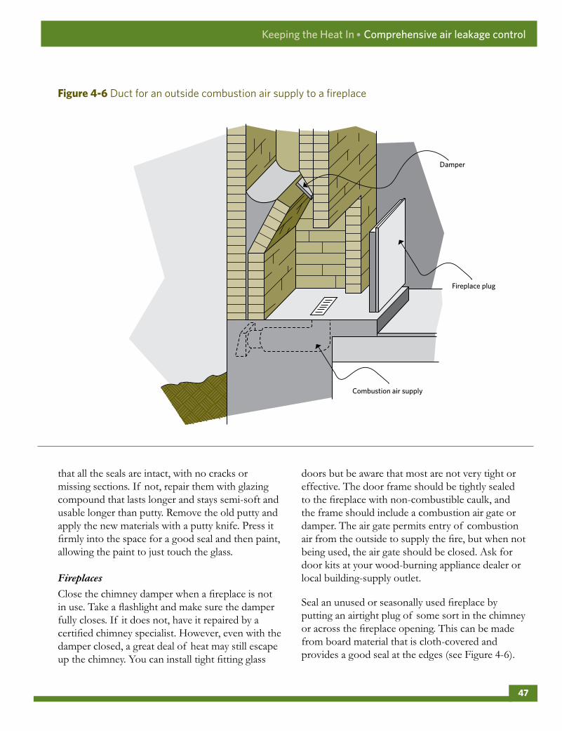
that all the seals are intact, with no cracks or missing sections. If not, repair them with glazing compound that lasts longer and stays semi-soft and usable longer than putty. Remove the old putty and apply the new materials with a putty knife. Press it firmly into the space for a good seal and then paint, allowing the paint to just touch the glass.
Fireplaces
Close the chimney damper when a fireplace is not in use. Take a flashlight and make sure the damper fully closes. If it does not, have it repaired by a certified chimney specialist. However, even with the damper closed, a great deal of heat may still escape up the chimney. You can install tight fitting glass
doors but be aware that most are not very tight or effective. The door frame should be tightly sealed to the fireplace with non-combustible caulk, and the frame should include a combustion air gate or damper. The air gate permits entry of combustion air from the outside to supply the fire, but when not being used, the air gate should be closed. Ask for door kits at your wood-burning appliance dealer or local building-supply outlet.
Seal an unused or seasonally used fireplace by putting an airtight plug of some sort in the chimney or across the fireplace opening. This can be made from board material that is cloth-covered and provides a good seal at the edges (see Figure 4-6).
Combustion air supply
Damper
Fireplace plug
Figure4-6 Duct for an outside combustion air supply to a fireplace
Keeping the Heat In ● Comprehensive air leakage control
47
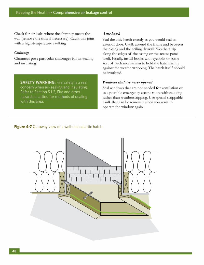
Check for air leaks where the chimney meets the wall (remove the trim if necessary). Caulk this joint with a high-temperature caulking.
Chimney
Chimneys pose particular challenges for air-sealing and insulating.
Attic hatch
Seal the attic hatch exactly as you would seal an exterior door. Caulk around the frame and between the casing and the ceiling drywall. Weatherstrip along the edges of the casing or the access panel itself. Finally, install hooks with eyebolts or some sort of latch mechanism to hold the hatch firmly against the weatherstripping. The hatch itself should be insulated.
Windows that are never opened
Seal windows that are not needed for ventilation or as a possible emergency escape route with caulking rather than weatherstripping. Use special strippable caulk that can be removed when you want to operate the window again.
SAFETYWARNING:Fire safety is a real concern when air-sealing and insulating. Refer to Section 5.1.2, Fire and other hazards in attics, for methods of dealing with this area.
Figure4-7 Cutaway view of a well-sealed attic hatch
Keeping the Heat In ● Comprehensive air leakage control
48

ROOFSANDATTICS
Relatively easy access has made the attic a favourite starting point to insulate for many homeowners, despite the fact that most other areas, such as basements and uninsulated walls, lose more heat than the typical attic. Even if an attic is already insulated, there may still be an opportunity to improve the energy efficiency and soundness of the house through air sealing. Air leaks into the attic can account for substantial heat loss and can lead to a variety of moisture-related problems.
The importance of air sealing cannot be overstated. Read this entire chapter if you are upgrading your attic for helpful tips and other relevant information.
Keeping the Heat In
5 Roofs and attics
5 .1 Generalconsiderationsforallattics
5 .2Easilyaccessibleattics
5 .3Houseswithhalfstoreys
5 .4Crampedattics,cathedralceilingsandflatroofs
5 .5Icedams
5 .6Renovationsandrepair
Figure5-1 Types of attics
One-and-a-half storey
Truss
Cathedral/flat roof/mansardAccessible
49

5 .1 GENERALCONSIDERATIONSFORALLATTICS
Regardless of the type of attic or ceiling your house has, there are a number of things to examine before beginning work. A thorough inspection of the following features will help you to develop your retrofit strategy.
Accessibility
Most houses with accessible attics have an interior ceiling hatch, although exterior roof or wall-mounted entries are not uncommon. A hatch should be large enough to allow you to bring in materials. If not, or if there is no access, you may be able to cut a hole in the ceiling in an inconspicuous place such as a closet. Exterior-mounted, gable-end entries represent one less opening that will have to be air sealed, which offers ready access to firefighters in the event of a fire.
Check the roof space for obstructions and ease of movement. Vertical clearances of less than 1 m (39 in.) will not allow you to move freely. Attics or roofs without a working space are covered later in this chapter, in Section 5.4, Cramped attics, cathedral ceilings and flat roofs.
Assessments
In addition to checking for structural problems, check the condition of the roof framing, sheathing, finish and the soffit and fascia for signs of moisture problems such as leaks, stains, mould, flaking or rot. Uncorrected moisture problems will reduce the effectiveness of insulation and can lead to structural damage such as wood rot or split rafters. Mould or rot are sure signs of advanced condensation problems. Identify the cause and correct it before adding insulation.
Figure5-2 Some attics are easier to work in than others
Keeping the Heat In ● Roofs and attics
50

Moisture can come from the outside due to failure of the roof or flashing. Typical problem areas include poor flashing at a hip, valley or the chimney and ice dam leaks. Pay particular attention to water marks on the underside of the sheathing or along rafters.
Moisture can also come from inside the house, carried into the attic as water vapour by air leakage. Typical problem areas occur around bathroom and kitchen vents that penetrate the ceiling, around plumbing stacks and chimney chases and at wiring penetrations and pot lights. A tell-tale sign of air leakage is the discolouration of insulation, so do not hesitate to look under existing insulation to locate air leaks.
Check the attic during or just after a cold snap for condensation buildup, which will appear as frost in cold climates. Some frost buildup is to be expected, but if it is particularly heavy buildup (10 mm [2 in.] or more), look to make sure ventilation is present and not blocked with insulation. Checking the attic during or just after a rainstorm will help determine whether moisture problems are generated by interior or exterior sources.
Examine the existing insulation for type, condition (dry, wet, compact, etc.), average depth and coverage. If it has been damaged or contaminated by mould or vermin, remove it. However, do not disturb vermiculite insulation (see Section 1.4, Health and safety considerations).
If the insulation is wet, do not cover it until the source of moisture is removed and the insulation is dry. If the insulation is dry, it will probably be all right to leave it in place. Generally, there is no problem in using two types of insulation. Check the depth of the insulation to determine its insulating value. Compare this with the recommended insulation values in Section 2.2, Control of heat flow.
Make sure that the insulation is distributed evenly and that there is full depth coverage, especially around the perimeter of the attic above the wall plates. Uninsulated areas will cause a cold spot where the wall and ceiling meet, which can lead to moisture and mould problems.
Existing air and vapour barriers
Houses should have a vapour barrier on the warm side of the insulation. In older homes, the vapour barrier might have been provided by wax paper, kraft paper-backed batts or layers of paint. Newer houses usually have a polyethylene sheet vapour barrier, but overall, very few houses have an effective air barrier.
If there is an air barrier, locate it and determine its condition. Remember, an air barrier must be continuous; holes or tears must be repaired, and penetrations sealed. Do not hesitate to pull back existing insulation where leakage sites might be found and seal these areas. However, do not disturb vermiculite insulation as previously warned.
Increased insulation means a colder attic, which in turn means that any vapour escaping into the attic can condense before it can be vented. It is essential to air seal the attic to prevent moist indoor air from getting in.
If there is no air and vapour barrier, concentrate on comprehensive air sealing. Create an effective air barrier by using caulking, gaskets and weatherstripping to seal the joints between building components. Do not rely on batt, blown-in or poured insulation to reduce the need for proper air sealing.
Keeping the Heat In ● Roofs and attics
51

5 .1 .2 Fireandotherhazardsinattics
Masonry chimneys
Check the chimney and surrounding framing for signs of charring, soot deposits, crumbling masonry or mortar, or evidence that the chimney lining is
deteriorating. Do not insulate it if the chimney is suspect. Have a chimney specialist repair, seal and insulate it at the same time.
Commonly a gap exists where a masonry chimney passes through the attic. To air seal this area, first install sheet metal flashing to bridge this gap and then seal all the joints with a non-combustible sealant (ensure the product is rated for this application). To prevent insulation, especially blown-in insulation, from coming into contact with the chimney, construct a barrier 75 mm (3 in.) from the face of the masonry chimney and a minimum 75 mm (3 in.) higher than the top of the insulation.
Figure5-3 Keep combustibles away from a masonry chimney
SAFETYWARNING:Certain areas in the attic can pose serious fire and health hazards. Before air sealing and insulating an attic, ensure you or your contractor address the following health and safety concerns.
Air and vapour barrier
High-temperature caulking
75 mm (3 in.) above insulation
Acoustical sealant
75 mm (3 in.) air space around chimney
Air space
Non-combustible flashing
Keeping the Heat In ● Roofs and attics
52

Metal chimneys
Factory-built metal chimneys should be kept from contacting insulation by a minimum 75 mm (3 in.) unless otherwise specified by manufacturer or local authorities. Install a non-flammable radiation shield that maintains a 75-mm (3-in.) air space between the chimney and insulation. To reduce air leakage, first air seal the fire stop to the air and vapour
barrier with non-combustible sealant. The top of the radiation shield should also be a minimum of 75 mm (3 in.) higher than the level of existing or new insulation to be added. To prevent insulation from falling behind the shield, attach a clamp-type storm collar without sealant at the top of the radiation shield.
Figure5-4 Keep combustibles away from a metal chimney
Storm collar (only clamped, not sealed)
Firestop installed from below
Ceiling trim plate
Radiation barrier to maintain the distance to the combustible material
High-temperature caulking
75 mm (3 in.) above insulation
75 mm (3 in.) air space
Air and vapour barrier wrapped around drywall to contact the firestop sealant
Keeping the Heat In ● Roofs and attics
53

Electrical installations
Work safely around electrical wiring (turn off the power). Consult with an electrical contractor if questionable wiring or corroded electrical connections are present.
Recessed lighting
Standard interior recessed lights are difficult to air seal effectively and can become a fire hazard if covered with insulation. Replace with approved airtight recessed fixtures or covers that can be installed safely under insulation.
Animal droppings
If you find a significant amount of animal droppings and vermin in the attic, do not disturb them because they can harbour easily airborne moulds, parasite eggs and bacteria that can cause severe illness. See Section 1.4, Health and safety considerations, for more information.
Figure5-5 Keep insulation away from a recessed light fixture by creating a barrier
Minimum box volume — allow 800 cubic centimetres (cm3) per watt of the fixture (e.g. a 150-watt the fixture would require a 120 000-cm3 box)
Centre the fixture if possible, keep it a minimum of 12.5 mm (1/2 in.) from the sides and top
Minimum 12.5-mm (1/2-in.) clearance, 150 mm (6 in.) preferred
12.5-mm (1/2-in.) plywood box lined with a fire-resistant material such as drywall or sheet metal to provide airspace around the fixture; caulk all joints and edges of the box to minimize air leakage
Keeping the Heat In ● Roofs and attics
54

5 .1 .3 AirsealingSeal the following areas:
• Around the plumbing stack and any other pipes. For plastic plumbing stacks that move up and down due to thermal expansion, use a flexible gasket or a polyethylene sleeve sealed to a plywood collar (see Figure 5-6).
• Around wires or ceiling light fixtures that penetrate the attic floor and partition and exterior wall top plates (see Figure 5-7 and Figure 5-8.) See Section 5.1.2, Fire and other hazards in attics, on how to deal with recessed lights.
• Around ducting that enters the attic from inside the house. Seal duct joints with aluminum duct tape or paint or mastic. Seal the gaps where
ducts penetrate the ceiling. The ducts should stay below the insulation or should be wrapped with insulation and be protected from being crushed. Exhaust fans should always discharge to the outside but not directly below the eave vents.
• At the junction of the ceiling and interior wall partitions, pull back the insulation to locate and caulk cracks along interior walls (see Figure 4-4).
• At the top of interior and exterior walls, check to see if all wall cavities are blocked from the attic (usually by a top plate). Block any open spaces in the exposed cavity with a piece of rigid board insulation and caulking. If the top plate is cracked or poorly fitted, use caulking and polyethylene to create a tight seal (see Figure 5-7).
Figure5-6 Sealing the plumbing stack
Pipe clamp
Plumbing stack
Heavy polyethylene strip (overlap, caulk with acoustical sealant and staple to the ceiling)
Keeping the Heat In ● Roofs and attics
55
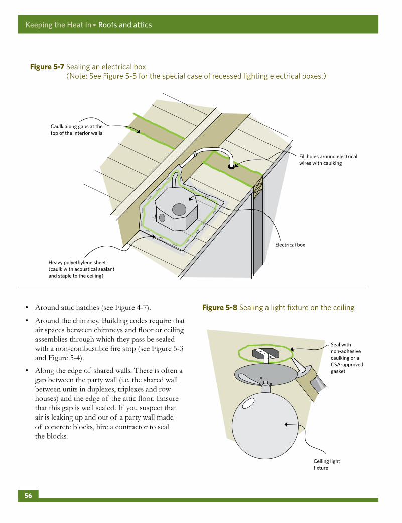
• Around attic hatches (see Figure 4-7).
• Around the chimney. Building codes require that air spaces between chimneys and floor or ceiling assemblies through which they pass be sealed with a non-combustible fire stop (see Figure 5-3 and Figure 5-4).
• Along the edge of shared walls. There is often a gap between the party wall (i.e. the shared wall between units in duplexes, triplexes and row houses) and the edge of the attic floor. Ensure that this gap is well sealed. If you suspect that air is leaking up and out of a party wall made of concrete blocks, hire a contractor to seal the blocks.
Figure5-7 Sealing an electrical box (Note: See Figure 5-5 for the special case of recessed lighting electrical boxes.)
Caulk along gaps at the top of the interior walls
Heavy polyethylene sheet (caulk with acoustical sealant and staple to the ceiling)
Fill holes around electrical wires with caulking
Electrical box
Figure5-8 Sealing a light fixture on the ceiling
Seal with non-adhesive caulking or a CSA-approved gasket
Ceiling light fixture
Keeping the Heat In ● Roofs and attics
56

5 .1 .4 VentilationAttic ventilation serves a number of purposes. It reduces summer heat buildup, prolonging the life of roofing and reduces air conditioner loads. After air sealing, attic ventilation is your second line of defence against the water vapour that may have found its way into the attic. It ensures a colder, well-vented attic space less prone to the formation of ice dams at the eaves.
Houses with peaked roofs and accessible attics are the easiest to vent by using the ratio of 1 to 300 (see below). This ratio refers to unobstructed vent area, so it must be increased if vents are covered with screening (to keep out insects, etc.) and with baffles (to keep out rain and snow), which reduce their clear area. Ideally, locate vents to allow for good cross ventilation from end to end and from top to bottom. However, although important, vents will not prevent condensation and will not solve the problems created by air leakage.
Make sure that existing attic vents are working properly and not blocked by insulation, debris or other materials. You may have to locate roof or soffit vents from outside if they are not clearly visible from inside the attic.
Although an airtight ceiling will significantly reduce the likelihood of moisture in the attic, building codes still require minimum attic ventilation. The ratio of vent area to ceiling area should be approximately 1 to 300.
Do not automatically increase ventilation. Also, do not use electric exhaust fans for attic ventilation as these can draw more air than can be supplied through the soffit vents. This will actually pull house air into the attic, resulting in greater heat loss and moisture accumulation. They are also prone to failure, noise production and increased energy use. Wind-driven, revolving roof vents do not create suction and are no more effective than other types of capped vents.
The location of vents is as important as their number and type. Often, a mixture of types and locations will work best. The following sections detail the best approach depending on your attic type.
5 .2 EASILYACCESSIBLEATTICS
After you have inspected the attic and carried out any remedial work, focus first on air and moisture control.
5 .2 .1 AirandmoisturecontrolThere are five options for installing an air barrier system in an unfinished attic:
• concentrate on air sealing
• install polyethylene over top of the joists
• install polyethylene between the joists
• spray foam between the joists (hire a contractor)
• spray foam under the roof to create a conditioned attic (hire a contractor)
The first option is the most practical, since installing a polyethylene air and vapour barrier in an existing attic is fraught with obstructions and requires painstaking attention to detail. On the other hand, spray foam offers air sealing and an initial layer of high quality insulation that can be topped up to the desired RSI (R) level.
If the attic retrofit is being completed in conjunction with interior renovations, the easiest approach is to install a new, single air and vapour barrier on the underside of the ceiling joists.
5 .2 .2 ConcentrateonairsealingIt is a good idea to paint the room side of the ceiling with two coats of oil-based paint or apply a single coat of latex vapour barrier paint to inhibit vapour movement. Ordinary latex paint is not a suitable vapour barrier.
Keeping the Heat In ● Roofs and attics
57

See Chapter 4, “Comprehensive air leakage control,” for detailed information on sealing all air leaks into the attic.
Install polyethylene over top of the joists
If the attic is relatively unobstructed with chimneys, plumbing stacks or structural members, consider installing polyethylene directly over the ceiling joists. This method involves the least number of seams and requires less caulking and stapling than other methods. It also leaves existing insulation in place. However, seal all obvious air leakage paths before laying down the polyethylene.
To avoid trapping moisture between the plastic and the ceiling, which might lead to possible wood rot or other moisture-related problems, install a minimum of twice the insulating value over top of the air vapour barrier (i.e. applying the one-third, two-thirds rule). For example, if the joist height is 89 mm (3 1/2 in.) and contains RSI 2.1 (R-12), install at least RSI 4.2 (R-24) over top of the polyethylene.
The main difficulty with this technique involves sealing the barrier to the wall top plate, especially at the eaves where there is little room to manœuvre. This area must be well sealed. Spray foam or rigid board insulation can help bridge the gap in this area. Cut rigid board to fit between the ceiling joists and to extend from the exterior wall top plate toward the attic. A second piece of rigid insulation, installed vertically, joins the polyethylene to the horizontal rigid board. Carefully caulk any joints or seams between materials. Expanding two-part spray foam kits (or the service of a spray foam company) are also very good for sealing areas around joists and boards.
Install polyethylene between the joists
Where obstructions, such as a truss roof, make the previous method too difficult, install a polyethylene air barrier or low-permeable foam insulation board between the joists. However, note that this is a lengthy and painstaking process.
Remove existing insulation from the area you are working on and set it to one side. Cut foam boards to fit snugly between the trusses. Caulk all edges, gaps and joints. Obstructions, such as electrical wires, will require cuts in the barrier; seal these carefully to make the barrier continuous. Another option is to cut the polyethylene strips about 200 mm (8 in.) wider than the joist spacing. Lay a bead of caulking on the side of the joists along their length and install the polyethylene using staples, installed through the caulk every 75 mm (3 in.) See Figure 5-10.
Spray foam between the joists
Spray foam contractors can install closed-cell foam between the joists to air seal and add insulation at the same time to the ceiling. All existing insulation and dust must be removed first to allow for a good bond. A minimum of 50 mm (2 in.) is needed; top up with other insulation afterwards.
Figure5-9 Installation of polyethylene sheets over attic joists
Rigid foam board at the eaves to maintain ventilation space
Keeping the Heat In ● Roofs and attics
58

Spray foam under the roof
This approach involves installing closed-cell spray foam directly under the roof surface, right down to the junction of the ceiling and exterior walls. This eliminates roof venting and creates what is called a hot roof, where the attic space becomes part of the conditioned (heated and cooled) house space. This process may be suitable for some attics, but do not proceed without approval from your building inspector, and then only use a certified spray foam contractor who is familiar with the process.
5 .2 .3 InstallinginsulationCommon materials for use in accessible attics are batt or blanket types or loose-fill insulation. If there are obstructions above the joists, such as with a truss roof, it may be easiest to put batt insulation into the joist spaces and then use loose-fill insulation to create a complete blanket of insulation above the joists and around all obstructions. Loose-fill insulation is also good by itself, especially in irregular or obstructed spaces.
Batt or blanket insulation
Fit batt insulation into place between the ceiling joists snugly, without compression. If the joist space is not the standard 16 or 24 in. (400 or 600 mm), cut the batts to fit the space or use loose-fill insulation.
Additional installation tips:
• Butt batt ends together as snugly as possible.
• Batts should cover the top plate of the exterior wall but not block the venting. To maintain airflow, leave a space of 38 to 50 mm (1 1/2 to 2 in.) between the top of the insulation and the underside of the roof sheathing. Use baffles between each rafter space to prevent it from being blocked (see Figure 5-11).
• Insulate above and below cross bracing, splitting or cutting the batt to accommodate the cross bracing as illustrated in Figure 5-12. Alternatively, cut one batt into a series of wedges and then fit a wedge under each brace. In either approach, do not compress the insulation.
Figure5-10 Foam board laid between the joists and caulked as an air and vapour barrier
Figure5-11 Baffles can be used to maintain airflow through the soffit vents
Keeping the Heat In ● Roofs and attics
59

• The first layer of batts should be thick enough to completely fill to the top of the joist space. The second layer can then run perpendicular across the joists to block any heat flow through and around the joists (see Figure 5-13). Ensure that there are no gaps between the two layers of insulation.
• Fill any awkward spaces or gaps with pieces of batt or with loose fill.
• Apply blanket insulation in the same way as batts. It may be pre-cut with a knife or cut on the spot. Start at one end of the attic and unroll the blanket.
Loose-fill insulation
• Loose-fill insulation can be poured by hand or blown in on top of the air and vapour barrier to a depth greater than the height of the joists. This task can be done by the homeowner using rented equipment or by a qualified contractor.
• Before adding insulation, nail enough depth indi-cators (e.g. a piece of wood nailed perpendicular to the joist) or mark highly visible lines on truss members so you can easily see and gauge the depth of the insulation. Maintain an even depth throughout the attic by levelling the insulation with a board or garden rake (see Figure 5-14).
• Fill all nooks and crannies.
• At the eaves, do not block the ventilation. Prevent insulation from disappearing into the eave space by installing a piece of rigid board insulation or a wood baffle before the work begins. Building-supply stores sell cardboard or foam plastic baffles that can be stapled between the rafters (see Figure 5-11). Be sure that the insulation extends out far enough to cover the top of the exterior wall.
• If the loose fill is deeper than the joists, build insulation framework (a crib) around the attic hatch so that it can be filled to the edge (see Figure 4-7).
Figure5-12 Fitting insulation around cross bracing
Figure5-13 The top layer of insulation runs perpendicular to the bottom layer
Keeping the Heat In ● Roofs and attics
60

• The bags of insulation material will list how many square metres (or square feet) each bag should cover to provide the required RSI value. Calculate the attic area to help determine the number of bags needed.
• If you are having a contractor do the work, calculate the RSI value that you want and check the bags of insulation to be used. They should indicate the area that one bag will cover at the selected insulating value. You and the contractor should then agree on the total number of bags to be used, the expected insulating value and the minimum settled depth of insulation throughout the attic, based on a specific density.
• Remember to seal the attic hatch (see Figure 4-7).
• Seal and insulate up to party walls in attached housing (see Section 5.1, General considerations for all attics).
• Do not cover recessed light fixtures unless they are installed in approved covers.
5 .2 .4 VentilationIdeally, 50 percent of the attic ventilation openings should be continuous soffit vents, and the other 50 percent gable, ridge or roof vents. Figure 5-15 shows various types of vents. Any of them are adequate when used in conjunction with soffit vents. Ridge vents are preferable where practical, but must be equipped with baffles to deflect wind blowing up the roof and to prevent the penetration of water and snow. Occasionally, a house will only have soffit vents. In this case, install gable end, ridge or roof vents to take advantage of cross ventilation.
Figure5-14 Installing loose-fill insulation
Note the markers that indicate the final depth of the insulation.
Different types of ventilation1. Soffit vents 3. Ridge vent2. Gable end vent 4. Roof vent
Figure5-15 Roof venting
3
1
42
Keeping the Heat In ● Roofs and attics
61

5 .3 HOUSESWITHHALFSTOREYS
Houses with 1 1/2 or 2 1/2 storeys have attics with several small sections that may make access, air sealing and insulating very difficult. If you cannot get into these spaces, you may have to hire a contractor. If the space is accessible, the following section gives some guidelines on how to do the work yourself.
5 .3 .1 AirandvapourcontrolWhere you have access to the attic space, follow the directions for the control of air and vapour flows as outlined in Section 5.2, Easily accessible attics.
Houses with half storeys have one major source of air leakage that must not be overlooked: through the ceiling joists immediately beneath the knee walls
(see Figure 5-17). This critical air leakage area must be sealed flush with the back of the knee wall finish. This can be done by cutting and fitting foam board that will fill that ceiling joist opening and seal it into place with caulking or spray foam.
Another option may be to dense-pack loose-fill insulation between the floorboards and the ceiling below while ensuring that an air barrier is installed.
5 .3 .2 VentilationVentilate the attic spaces above and beside the top storey separately by using gable vents. Position the vents to prevent wind from blowing through the insulation.
A second option is to use gable vents in the area above the attic ceiling and eave vents in the side areas. This is a good option if the house already has working eaves vents (see Figure 5-19). A ventilation space in the rafter section will permit airflow between the insulated areas.
Figure5-16 The wall and floor sections of a half storey should be insulated
Figure5-17 Rigid insulation can be nailed over the studs of the knee-wall section
Vent space
Foam boardCaulking
Attic rafter vent
Keeping the Heat In ● Roofs and attics
62

Otherwise, you will have to install rafter vents in the section along the rafters to ensure adequate ventilation (see Figure 5-18 and Figure 5-19). These vents must be on the cold side of the space, while the warm side can be filled with insulation that can be added to the sloping ceiling portion unless other arrangements are made in the renovation process.
5 .3 .3 InsulationSpray foam and rigid foam insulation can be used, but batts are less expensive and easier to handle in confined spaces. If there are any electrical outlets (use care to avoid shocks – and also take this opportunity to upgrade wiring in this area) or pipes in the knee wall, keep them on the warm side of the air and vapour barrier and insulation, and seal the air and vapour barrier around them.
• Treat the attic floor behind the knee wall and the attic space above the half storey’s ceiling (see Figure 5-17) exactly as described previously for a standard, unfinished attic; in addition, add air sealing under the knee wall.
• Treat end walls as described in Chapter 7, “Insulating walls.”(End walls are the full-height walls that are exposed to the exterior.)
• The knee wall can be treated like an unfinished attic floor (see Figure 5-9), making allowances for the fact that it is vertical. Install a combination air and vapour barrier made from polyethylene strips sealed between each stud. Sealing all cracks and penetrations and painting a vapour barrier on the interior surface also can create the air barrier. Next, install the insulation and secure it in place with building paper, cardboard, olefin sheets or chicken wire. Better yet, nail 25 mm (1 in.) or more of rigid board insulation to the exterior side of the studs to hold the insulation. This will also increase the thermal resistance of the wall section and reduce thermal bridging. A wall in the attic that adjoins a heated space can also be insulated like a knee wall.
• The section between the rafters may be filled with insulation if all penetrations through the ceiling
Figure5-18 Each section has its own cross ventilation
Figure5-19 Ventilation occurs between sections through attic rafter vents installed in the rafter section
Baffle
Air space
Baffle sealed at the rafter
Keeping the Heat In ● Roofs and attics
63
are sealed and if this is permitted by local building codes or standards (see hot roof in Section 5.2.2, Concentrate on air sealing, subsection Spray foam under the roof). The hot roof could involve the slope ceiling and then the knee wall space. It is unlikely to be necessary in the small triangular top attic. Having an insulated roof slope allows the knee wall spaces to be used for storage (as they often are).
• Exposed foam in accessible areas must be fire protected.
• Due to limited space for insulation and venting on the sloping ceiling, consider adding rigid board directly to the ceiling, and then air seal and cover with drywall. This method will greatly increase comfort levels in summer and winter, though it may reduce headroom.
• Some contractors specialize in high density blown insulation that will help reduce airflow while improving thermal values.
Dormer windows
Many 1 1/2 or 2 1/2 storey houses have dormer windows. The walls of the dormer may be insulated with batts, as described for the knee wall. Dormers typically include a lot of framing members that limit the amount of insulation that can be added. Besides air sealing, consider dense-pack blown-in insulation and also the addition of rigid board insulation and drywall to reduce thermal bridging.
Floorboards
Some houses will have the attic floored over, even when it is not used as living space. You can insulate it by lifting the floorboards and treating it as you would an unfinished attic, though some or all of the boards may have to be replaced to maintain the ceiling stiffness.
Alternatively, a contractor can fill the subfloor space completely by blowing in dense-pack loose-fill insulation through access holes. Air leaks, such as around plumbing stacks and open eave spaces, should
be sealed first. With the contractor, ensure that the space is filled completely and at the right density.
You will not likely be able to achieve the minimum manufacturer’s recommended levels for attic insula-tion by filling this space alone. If possible, add some insulation on top of the floorboards to keep them warm and to reduce thermal bridging through the joists and floorboards.
5 .4 CRAMPEDATTICS,CATHEDRALCEILINGSANDFLATROOFS
This section discusses methods for insulating difficult areas.
5 .4 .1 CrampedatticsThere are three options for insulating an attic that is too cramped to work in:
• Insulate on top of the existing roof (see Section 5.5, Ice dams).
• Add rigid board and drywall to the ceiling if there is adequate headroom.
• Have an experienced contractor blow in dense-pack loose-fill insulation.
The last two options can also be done together. The first and last methods may apply where there is inadequate headroom.
SAFETYWARNING:Before insulating, check for wiring (replace damaged or frayed wiring), recessed light fixtures or other sources of heat that may be concealed beneath the floorboards. All heat sources must be protected from the insulation or removed entirely.
Keeping the Heat In ● Roofs and attics
64

There will likely be no way of installing a new sheet-material air barrier. If one does not already exist, it should still be acceptable to install insulation if there is no evidence of moisture problems, if humidity levels in the house are reasonable and if any air leaks through the ceiling into the attic are sealed. You can achieve added protection by painting the ceiling below the attic with latex vapour barrier paint (ask paint suppliers or manufacturers) or two coats of oil-based paint.
Ensure that the contractor prevents insulation from entering the eaves and blocking the ventilation. If there are any recessed light fixtures, chimneys or other sources of heat in the attic, make sure precautions are taken to avoid creating a fire hazard.
Ventilating cramped attics can be difficult because of the difficulty of creating an adequate airflow. Where the roof extends past the exterior walls, it may be possible to use soffit vents in combination with roof vents or built-up ridge vents.
Many houses with cramped attic spaces lack eaves. In such cases, approach ventilation with caution. The best approach is to carefully seal the ceiling below the attic from inside the house and then insulate without installing additional vents.
If possible, check the roof space for moisture problems during or just after a cold snap in mid-winter. Some frost is to be expected, but if the buildup is especially heavy, you will have to vent the space, thoroughly seal all air leaks and reduce humidity levels in the house. Check with local building authorities to determine which procedures are permitted in your area.
5 .4 .2 CathedralceilingsandflatroofsA house (or any portion of a house) with a flat roof, cathedral ceiling or some other attic-less construction is difficult and will require the services of a qualified contractor.
The main problem with these roofs is the limited space for insulation and ventilation. If there is
already some insulation in the joist space, trying to add more may not be beneficial. However, if you decide it is worth your while to increase insulation levels, there are a number of options. Each option involves some risk of either moisture problems or thermal bridges that can reduce the effectiveness of the insulation. A technique involving blown insulation is discussed below.
Section 5.6, Renovations and repair, discusses both interior and exterior retrofits, including the addition of a new roof. The existing space between the ceiling and roof can be dense-packed with cellulose or glass fibre loose-fill insulation by a contractor. Densities are typically between 56 to 72 kg/m3 (3 1/2 to 4 1/2 lb./cu. ft.). The contractor should calculate and confirm the density for each roof cavity.
This approach eliminates roof ventilation, so it is generally not recommended (check with local building authorities first). However, the high density of the insulation, combined with comprehensive air sealing, should reduce airflow sufficiently to avoid condensation problems.
Figure5-20 Flat roof
Soffit vent
Air flow
Keeping the Heat In ● Roofs and attics
65
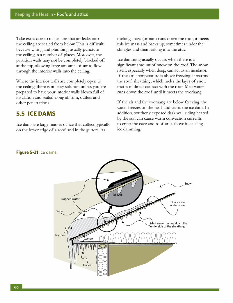
Take extra care to make sure that air leaks into the ceiling are sealed from below. This is difficult because wiring and plumbing usually puncture the ceiling in a number of places. Moreover, the partition walls may not be completely blocked off at the top, allowing large amounts of air to flow through the interior walls into the ceiling.
Where the interior walls are completely open to the ceiling, there is no easy solution unless you are prepared to have your interior walls blown full of insulation and sealed along all trim, outlets and other penetrations.
5 .5 ICEDAMS
Ice dams are large masses of ice that collect typically on the lower edge of a roof and in the gutters. As
melting snow (or rain) runs down the roof, it meets this ice mass and backs up, sometimes under the shingles and then leaking into the attic.
Ice damming usually occurs when there is a significant amount of snow on the roof. The snow itself, especially when deep, can act as an insulator. If the attic temperature is above freezing, it warms the roof sheathing, which melts the layer of snow that is in direct contact with the roof. Melt water runs down the roof until it meets the overhang.
If the air and the overhang are below freezing, the water freezes on the roof and starts the ice dam. In addition, southerly exposed dark wall siding heated by the sun can cause warm convection currents to enter the eave and roof area above it, causing ice damming.
Figure5-21 Ice dams
Icicles
Ice dam
Trapped waterThin ice slab under snow
Melt snow running down the underside of the sheathing
Snow
Snow
Ice
DETAIL
Keeping the Heat In ● Roofs and attics
66
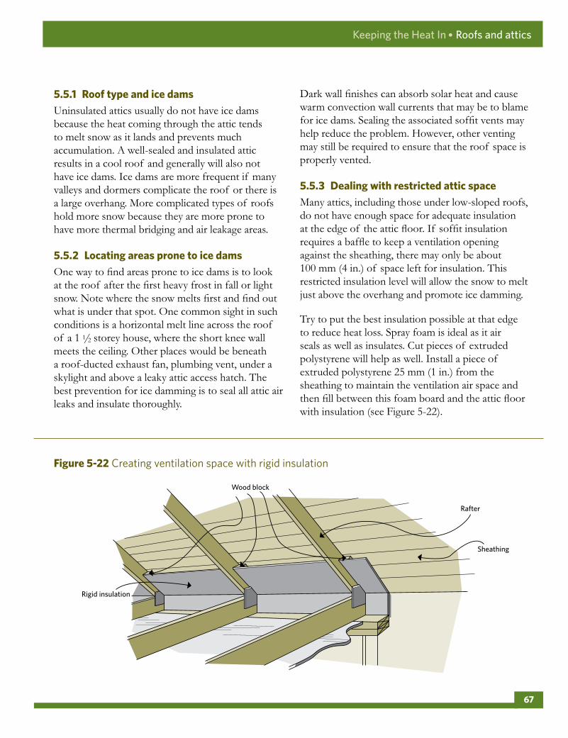
5 .5 .1 RooftypeandicedamsUninsulated attics usually do not have ice dams because the heat coming through the attic tends to melt snow as it lands and prevents much accumulation. A well-sealed and insulated attic results in a cool roof and generally will also not have ice dams. Ice dams are more frequent if many valleys and dormers complicate the roof or there is a large overhang. More complicated types of roofs hold more snow because they are more prone to have more thermal bridging and air leakage areas.
5 .5 .2 LocatingareaspronetoicedamsOne way to find areas prone to ice dams is to look at the roof after the first heavy frost in fall or light snow. Note where the snow melts first and find out what is under that spot. One common sight in such conditions is a horizontal melt line across the roof of a 1 1/2 storey house, where the short knee wall meets the ceiling. Other places would be beneath a roof-ducted exhaust fan, plumbing vent, under a skylight and above a leaky attic access hatch. The best prevention for ice damming is to seal all attic air leaks and insulate thoroughly.
Dark wall finishes can absorb solar heat and cause warm convection wall currents that may be to blame for ice dams. Sealing the associated soffit vents may help reduce the problem. However, other venting may still be required to ensure that the roof space is properly vented.
5 .5 .3 DealingwithrestrictedatticspaceMany attics, including those under low-sloped roofs, do not have enough space for adequate insulation at the edge of the attic floor. If soffit insulation requires a baffle to keep a ventilation opening against the sheathing, there may only be about 100 mm (4 in.) of space left for insulation. This restricted insulation level will allow the snow to melt just above the overhang and promote ice damming.
Try to put the best insulation possible at that edge to reduce heat loss. Spray foam is ideal as it air seals as well as insulates. Cut pieces of extruded polystyrene will help as well. Install a piece of extruded polystyrene 25 mm (1 in.) from the sheathing to maintain the ventilation air space and then fill between this foam board and the attic floor with insulation (see Figure 5-22).
Figure5-22 Creating ventilation space with rigid insulation
Rafter
Sheathing
Wood block
Rigid insulation
Keeping the Heat In ● Roofs and attics
67

5 .5 .4 CathedralceilingsIce dams on roofs with cathedral ceilings are more difficult to resolve as they are harder to access. The same principles apply to preventing ice dams – stopping house air leaks, upgrading insulation, possibly improving roof ventilation. Ice dam issues on cathedral-type roofs are usually best dealt with by contracting an insulator with dense-pack insulation experience or when re-roofing.
5 .5 .5 InstallinganewroofWhen re-roofing, remove the roof finish and the sheathing, air seal and fill the cavities with insulation and then install the new roofing materials, including an ice-shield membrane. A well-sealed roof will need little to no ventilation. If you are uncertain about whether or not the sealing can be done effectively, leave a ventilation channel under the sheathing from the soffit to the peak. Sometimes insulation can be added to the ceiling inside, although this approach will not stop the air leakage.
An alternative measure to prevent ice dams is to make the roof impermeable by using a self-sealing membrane under the shingles. Building codes require such membranes on the lower part of the roof in new houses. These membranes do not stop ice dams, but they prevent the water from leaking through the roof sheathing and into the house. Ice damming can still occur and possibly damage shingles and gutters.
5 .5 .6 QuickfixesandtheirlimitationsThere are many popular, quicker solutions but they have drawbacks:
• Attaching electric heating cables will melt channels in the ice, sometimes alleviating a problem, but they use a significant amount of electrical energy while being an eyesore on most roofs.
• Removing gutters will keep them from becoming ice traps, but gutters keep roof water away from the foundation.
• Attacking ice dams every winter with an axe or ice pick will damage the roof surface.
• Although removing snow from the roof will also help, removing ice dams and snow is not always easy or safe to do.
• For certain older houses with complicated roofs, it may be impossible to completely eliminate ice dams without resorting to several different techniques.
The preferred solution for most houses is to keep house heat out of the attic by air sealing and insulating.
5 .6 RENOVATIONSANDREPAIR
Renovations or repairs provide an opportunity to ensure a well-insulated attic ceiling and walls with an effective air and vapour barrier.
A popular renovation activity is to convert an existing unfinished attic into a new living space. Depending on the depth of the rafter space, it may be difficult to achieve the recommended high attic RSI values. If you choose to finish your attic, check for local code requirements and then consider the following steps:
• Install collar ties between every pair of rafters (see Figure 5-23). These ties will provide structural support for both the roof and the new ceiling.
• Ensure that the insulation installed in the rafter spaces fits snugly against the top of the walls to form a continuous thermal envelope. There must be no gaps around the perimeter of the attic floor, otherwise heat will escape and ice damming may occur near the eaves. In most cases, it should be possible to insulate each rafter space all the way down to the eaves and over the top of the exterior wall. Leave a clear space between the top of the insulation and the underside of the roof sheathing to allow for
Keeping the Heat In ● Roofs and attics
68

roof ventilation. Seal any roof vents into the parts of the attic that are not heated.
• Staple a continuous polyethylene air and vapour barrier to the rafters and end-wall studs; then carefully seal the edges and seams with acoustical sealant.
• If your attic is not too cramped, consider adding strapping onto the rafter bottoms and wall studs to allow for more insulation (up to the recommended minimum level for attic insulation, if possible). After installing insulation in the existing cavities, nail or screw strapping (2 x 2 or 2 x 3 on-edge) perpendicular to the rafters and studs. Space the strapping to suit the width of the insulation you will use. However, the strapping should be no more than 610 mm (24 in.) apart – measured on centre – or you will have difficulty attaching the interior finish. Fit insulation snugly between the strapping, covering all the rafters and studs. Finally, staple a continuous, sealed polyethylene air and vapour barrier to the strapping. Alternatively, secure rigid board insulation 25 to 50 mm (1 to 2 in.) to the rafters and studs, seal or install a vapour barrier and then cover with an approved finish (e.g. drywall).
• Insulation between the collar ties is applied from below in much the same way, with a continuous polyethylene air and vapour barrier applied last. If the collar ties have already been insulated and if there is access to the upper portion, then more insulation may be added as in a normal attic.
5 .6 .1 DroppedceilingWhere headroom is sufficient, constructing a dropped ceiling to hold insulation is an excellent way of thermally upgrading a cathedral ceiling or flat roof, especially when planned as part of a renovation. The following are several options:
• Construct a new ceiling immediately below the existing ceiling. If the roof has exposed joists or beams (usually for decorative purposes), it may be possible to close the space, which creates a new ceiling. Install batts or rigid insulation in the space followed by a continuous air and vapour barrier and a new ceiling. In all cases, you must prevent warm air from getting into the new cavity space and bypassing the insulation. Seal the perimeter of the new ceiling and any possible air leakage paths through partition walls.
• With the ceiling removed, extend existing rafters or trusses to accommodate additional insulation. Cross strap the existing rafters or extend the rafter cavity with 2 x 4 lumber and plywood gussets (see Figure 5-24).
Although it is not necessary to remove the interior finish and expose the rafters and tops of the walls when constructing a new ceiling, it is a good idea. This will allow you to perform air sealing, check the state of the insulation and verify if there is a vapour barrier.
• Mechanically fasten rigid board insulation directly to the structure of an existing ceiling. Although this technique avoids the mess and time required to tear down the ceiling, it will make access to the space between the ceiling and the attic floor more difficult (e.g. to install
Figure5-23 Collar beams (collar ties) provide additional support
Keeping the Heat In ● Roofs and attics
69

recessed light fixtures). If rigid board insulation doubles as the air barrier, fit the boards tightly and seal the seams well. Extend electrical fixtures to accommodate the depth of the new ceiling.
5 .6 .2 AddinganewroofInsulation can also be added on top of an existing ceiling or roof. This option is most suitable for cathedral ceilings and flat roofs when major exterior alterations, such as a new roof, are required. Air sealing, installing new insulation, sheathing, roofing surface and replacing eavestroughs, soffits and fascia plus disposal will cost several thousand dollars. You will almost certainly need the services of a qualified contractor.
One method involves installing rigid board insulation on top of the existing roof (see Figure 5-25). The higher RSI value of rigid insulation means a smaller increase in the roof thickness, although several layers of insulation may be needed to meet the desired RSI level.
Sheet polyethylene is first placed on the existing roof to provide the air and vapour barrier, following the 1/3 – 2/3 rule. Alternatively, a layer of closed-cell spray foam or low-permeability rigid board can be installed with the joints taped to prevent air leakage. This step is not necessary if an air barrier is already in place.
Figure5-24 Extending the rafters provides space for insulation and ventilation
Keeping the Heat In ● Roofs and attics
70

It is important to insulate (i.e. block) and air seal the spaces between the joists along the perimeter of the roof. This prevents heated air from escaping around the insulation. Line up the edges of the blocking material with the inside finish of the exterior wall and thoroughly caulk all seams. Another approach is to hire a spray foam contractor familiar with air sealing to block these critical areas.
Another method is to build up the existing roof or to frame a new roof and fill it with batt insulation or loose-fill insulation, which is blown in. Ensure that the air and vapour barrier is tightly sealed. The new space or roof frame may add to the structural loading of the entire assembly, so this must be done following local code requirements.
This approach is best done with new trusses or by installing cross members (called purlins) that span the length of the roof. Once the purlins are in place, the new rafters are installed, followed by the proper installation of the insulation to avoid air movement and thermal bridging. Leave enough clear space above the insulation and above the new roof rafter to allow for ventilation.
Figure5-25 A new insulated roof can be built over the old roof
Blocking insulation
Keeping the Heat In ● Roofs and attics
71

Keeping the Heat In
6 Basement insulation
6 .1 Insulatingthebasementfromtheoutside
6 .2 Insulatingthebasementfromtheinside
6 .3 Crawlspaces
6 .4Openfoundations
6 .5 Concreteslabongrade
BASEMENTINSULATION
Basements can account for about 20 percent of a home’s total heat loss. This is due to the large, uninsulated surface area both above and below grade level. Contrary to popular opinion, earth is a poor insulator. There is also a lot of air leakage through basement windows and penetrations (including cracks in these areas) and at the top of the foundation wall (sill area).
Many basements have little or no insulation, so this means there is much potential for improvement. Insulating can often be tied in with other repairs or renovation work such as waterproofing, radon remediation or finishing the basement.
Figure6-1 Heat loss in a basement
72

Types of basement construction
The most common type of construction is the full foundation basement, with mainly below grade foundation walls supporting the house structure. Many houses have been built with partial depth foundation walls that create a crawl space under the house. Some older homes, cottages or mobile homes are built up on posts and piers, leaving the space below the house open or walled off. Other houses are built on a slab-on-grade where there is no basement or crawl space at all.
i) Concrete foundations
Poured or concrete block foundations have been built since the 1920s, usually with parging, waterproofing and drain tiles on the exterior. However, anything more than 20 years old may need some repair. This type of foundation can be insulated from the outside or inside if no serious water or structural problems exist.
ii) New houses or new foundations under older houses
If the house is new or it has been raised to accommodate a new basement, allow about a year of drying out time before insulating or renovating. As concrete contains large amounts of moisture, it
is best to let it dry before insulating and finishing unless the renovation method to be used can handle this entrained moisture.
iii) Older rubble, brick or stone foundations
Older foundations are often uneven and can vary in depth and thickness. These foundations were rarely damp-proofed; some have an interior drainage path and all have a high mortar content, which can absorb water from the soil. They are best insulated from the outside, but some interior insulating is possible. Always obtain expert advice before proceeding on remediation.
iv) Other types of foundations
Many newer homes are built with preserved wood foundations. They are damp-proofed and are generally fully insulated.
Basement assessment
Before planning the job, assess the status of your basement. Here are some of the problems to look for:
i) Water leaks
Major water leaks, such as persistent leaks and flooding in the spring and when it rains, must be corrected. Often the solution requires excavating, damp-proofing or waterproofing the basement, adding a drainage system and insulating from the exterior.
Minor water leaks can sometimes be corrected by directing water away from the foundation by sloping the grade, aiming downspouts away from the house and patching the foundation on the interior.
Correct any problems with sump pumps or sewer backup before beginning the insulation job.
Figure6-2 Common foundation types
Rubble Brick Poured concrete
Concrete block
Keeping the Heat In ● Basement insulation
73

ii) Dampness
Symptoms of dampness on foundations and finishes include staining or mould growth, blistering and peeling paint, efflorescence (a whitish mineral deposit on the surface), spalling (deterioration of the surface) as well as a musty smell. Minor dampness may be corrected from the interior; more serious problems should be corrected from the outside. Condensation can also form on the foundation walls in the summer when the air is very humid and the foundation is cool.
Checking for dampness
If the foundation walls, slabs and earth floors appear dry yet the space seems damp, this might indicate that moisture is wicking through the foundations and evaporating faster than it can accumulate.
To test for this, cut a sheet of plastic about 1 m (40 in.) square and tape it to the concrete walls and slab. For earth floors, hold down the edges with sand or sticks. After a day or two, check the plastic. If condensation formed on the top of it, this indicates high interior moisture levels. (See details in Section 2.4, Control of moisture flow and Section 9.4, Ventilation and combustion air.)
Carefully remove the plastic and note any condensation on the bottom of the plastic or wetting of the concrete or soil. Condensation formed under the plastic indicates moisture movement from the ground into the home as well as the possibility of radon emissions.
To reduce the movement of moisture into the home from the foundations, apply a moisture barrier (see Section 6.3, Crawl spaces) or have the interior or exterior concrete sealed or waterproofed.
iii) Cracks
If the basement has an active crack (i.e. one that gets bigger or smaller), seek professional help to determine if the situation requires structural repairs.
iv) Radon
Radon may be present in all homes, with and without humidity and moisture problems (see Section 1.4, Health and safety considerations, for more information).
Insulate inside or outside?
Insulating on the outside is best, but it is often necessary to insulate from the inside for economical and practical reasons. Sometimes a combination of approaches is required. Examine the advantages of each approach carefully.
i) Insulating inside
This may involve installing rigid insulation board and drywall, a wood-frame wall and insulation or other combinations of insulation. Your choice of method will depend on a number of factors, including whether there are moisture issues, the need to account for moisture and air/vapour barriers, how you plan to use the space and, finally, cost.
Advantages of inside insulation
• It can be incorporated into a plan to finish the basement.
• The work can be done at any time of the year and can be done one section at a time. Often all or part can be a do-it-yourself job.
• It is often easier and cheaper to insulate the full wall and achieve high insulating values.
• The landscaping and driveway will not be disturbed.
Disadvantages of inside insulation
• Do not insulate a basement with moisture problems from the inside (leaks, dampness, efflorescence and blistering paint). If you must, take corrective measures to eliminate the moisture before adding insulation or your new walls will rot.
Keeping the Heat In ● Basement insulation
74

• Adding insulation to the inside will make the foundation walls even colder. Any humid air that comes in contact with these cold walls will condense. Interior finishes hide or obscure moisture problems as they develop. This can lead to long-term mould exposure as people are less likely to fix a moisture problem if they have to remove finishing that they have erected.
• Obstructions such as electrical panels, wiring, plumbing, stairs and partition walls make the work more difficult and the insulation and air barrier less effective. If part of the basement wall is already finished, this too may prove troublesome, although wall paneling may be easy to remove and re-install.
ii) Insulating outside
This involves excavating around the foundation, waterproofing and installing insulation, as per Figure 6-3. Flashing must be attached to keep water from getting behind the insulation and a protective covering installed on exposed sections of insulation.
Advantages of outside insulation
• The outside wall tends to be more continuous and easier to insulate.
• You can effectively see and correct any moisture or structural problems (efflorescence, cracks, spalling and eroded mortar). Rubble or brick foundations and foundations with water leakage, dampness or other moisture problems should be insulated from the outside. Repairing the foundation, parging, waterproofing and installing a drainage system can be done at the same time.
• There is no disruption in the house, no interior work disturbed and no inside space lost.
• Freeze-thaw stresses are eliminated, and frost is unlikely to penetrate down to the footings.
• The mass of the foundation is within the insulated portion of the house and will tend to even out temperature fluctuations.
Disadvantages of outside insulation
• Digging a trench around the house by hand can be difficult and risky depending on soil type and depth. It is much easier to use machinery but access could be a problem.
• Storing the dirt can be a problem.
• Excavation cannot be done in winter and can be a problem in the spring or throughout the year if the property has a high water table.
• Features such as non-removable steps, paved carports, shrubbery, trees or fences can make the work difficult.
• Rubble or brick foundations could be partially supported by the soil. Get expert advice before starting.
• It is expensive to obtain high insulation levels, and the retrofit may detract from the appearance of the house.
TECHNICALNOTE:Some authorities have expressed concern about the possibility of frost action and structural damage when foundations are insulated from the inside. The concern is that frost will penetrate deeper down the outside of the foundation wall. Research has found that this is not a problem.
Under some circumstances, such as in soils that are particularly frost-susceptible in extreme climates, there could be a problem caused by some construction techniques. Check with your local building authorities or find out if your neighbours have experienced any difficulties with frost action on their foundation.
Keeping the Heat In ● Basement insulation
75

6 .1 INSULATINGTHEBASEMENTFROMTHEOUTSIDE
Further to the previous introduction, assess the following before beginning work:
• outside features such as buried and surface services, access and lot lines inhibiting excavation
• insulation requirements (type and thickness, height and depth) finishing details (protective coating, flashing)
• tools and equipment required (for excavating, water-sealing, insulating, etc.)
6 .1 .1 SpecialsafetyconsiderationsRefer to Section 1.4, Health and safety considerations, for general advice on safe working procedures.
For every underground service that enters your home (e.g. gas, electricity, telephone, water and sewage), find out where each is located before you begin digging. Utilities provide this service at no cost.
How to insulate outside the basement
The work may require several weeks of effort. Plan for extra time if you need to excavate, repair cracks, waterproof the exterior foundation walls and install a drainage system.
Insulating the outside of the basement includes the following steps:
i) Dig the trench
The excavation should ideally go down to the footings but never below. The trench should be wide enough to work in. It is a big job, so do not make it even bigger with an oversize trench. Digging may be done by hand or using appropriate machinery. The excavated dirt can be stored on a tarp or sheet of polyethylene at least 610 mm (24 in.) away from the excavation.
SAFETYWARNING:In particular, follow safe trenching practices to avoid accidental burial and trench collapse. Protect the trench from running water and the elements, and ensure that people and animals cannot fall in. Some soils are not stable and may require bracing to prevent collapse. If you are doing this yourself, consult local building authorities for advice on proper shoring and trenching practices. Figure6-3 Components of exterior insulation
Exterior insulation involves1. excavation 4. drainage system and backfill2. waterproofing 5. protective coating and flashing3. insulation
4
2
1
5
3
Keeping the Heat In ● Basement insulation
76

In some cases it may only be practical to install insulation to a minimum of 610 mm (24 in.) below grade, especially when the foundation walls and drainage system are in good condition. This will reduce the excavating required while still offering substantial thermal protection, and can be coupled with further interior insulating. An optional horizontal rigid insulation skirt can also be added to reduce heat loss to the surface, which can mitigate frost-related problems (see Figure 6-4).
ii) Prepare the surface and site
First clean the surface of the foundation with a wire brush and scraper or use a pressure-washer if you can easily remove the water. Inspect and repair any major holes, cracks or damage and then seal
all penetrations. Smooth or replace deteriorated surfaces and old parging with an appropriate type of new parging. Allow repairs to dry.
Check the condition of the drainage tiles and repair as needed. Install a drainage system if one does not exist but only if it can be done properly (i.e. one that can drain to an appropriate discharge). It is best to do this task after completing work on the foundation wall. Consult a drainage systems expert before proceeding.
Have a contractor apply waterproofing material from grade level down to and over the top of the footings, and then seal all penetrations and overlaps. Sheet materials, sprays and roll-on compounds are available. Follow all manufacturers’ directions.
Figure6-4 Exterior basement insulation
Minimum 600 mm (24 in.) below the grade line
Optional — extend insulation 600 mm (24 in.) horizontally sloping away from house
Optional — extend insulation 600 mm (24 in.) horizontally sloping away from house
Flashing Flashing
Floor joist Floor joist
Rigid insulation Rigid insulation
Sand bed, if required
Sand bed, if required
Basement wall Basement wall
Footing Footing
Drain tile Drain tile
Protective covering Protective covering
Grade line
A) Minimum B) Full Depth
Keeping the Heat In ● Basement insulation
77

iii) Apply the insulation
Three types of insulation are used on the exterior of basement walls: rigid mineral wool boards, high-density polystyrene (Type IV) and polyurethane/ polyisocyanurate boards. (See Section 4.2, Caulking and other air sealing materials, for more information.)
Type IV polystyrene board is the material most commonly used in exterior below-grade applications (see Figure 6-3 and Figure 6-4).
Insulation with drainage capability (see Figure 6-5), such as mineral wool board, must be used only if:
• It is applied to the full depth of the foundation wall.
• There is a drainage system.
• The insulation has no horizontal seams that break the drainage path.
Measure and cut the insulation to the desired height (generally from the top of the footings to the exterior wall flashing). Start installing the insulation at one corner, overlapping at the corners and keep the insulation sheets as tight to the wall as possible (see Figure 6-6).
Figure6-5 Draining-type insulations must be installed vertically all the way down to the footings
Figure6-6 The insulation should overlap at corners
A drain tile is essential.
TECHNICALNOTE:Some experts suggest using two layers of insulation with overlapping joints. The insulation is held in place at the top edge by the flashing and by using corrosion-resistant fasteners and washers. The below-grade portion of the insulation will be held in place by the backfill, but may require some fasteners to hold it in place during the process.
Insulation
Drainage tile
Keeping the Heat In ● Basement insulation
78

It may be convenient (although more expensive) to purchase a special interlocking system of grooved polystyrene boards with steel channels. These should be used in the above-grade portion only to a depth of 305 mm (12 in.). There are also special clips and fasteners for applying the rigid board to the wall; check building-supply stores.
Apply parging to rubble and brick foundations to smooth the wall after all repairs have been completed. The type and flexibility of the insulation will determine the smoothness of the parging required. The correct parging material will also act as a sacrificial surface material to help protect the mortar in the foundation wall. Waterproof the parging, insulate and then proceed as noted above.
iv) Apply the flashing
Flashing helps keep the insulation in place, prevents water from getting behind it and provides a clean, neat junction. There are two major considerations:
the location of the flashing, which defines how far up the wall the insulation extends, and the type of flashing used.
If the siding can be partially removed or pried up, use standard Z-flashing inserted at least 50 mm (2 in.) behind the siding and building paper (i.e. behind the drainage plane). If you cannot insert flashing behind the siding (such as with brick), then either a metal J-channel must be installed prior to the insulation or a wood flashing installed after the insulation.
Flashing should accommodate the width of the insulation and protective coat. Wood flashing should be sloped with an overhang of at least 20 mm (3/4 in.) and have a drip edge on the underside.
For wood flashing or a J-channel, seal the joint between the flashing and the house with a suitable caulking.
Figure6-7 Types of flashing for a foundation – first floor transition
J channel Z flashing Wood flashing
Keeping the Heat In ● Basement insulation
79

For brick siding, keep the weep holes open that allow water to escape from behind the brick.
Ideally, carry the insulation up past the header area by at least 150 mm (6 in.) as shown in Figure 6-8. This often cannot be done because of practical or aesthetic reasons. If the insulation is carried up only to the header area or lower, then air seal and insulate the header area from the interior. This is described later in this chapter.
v) Protect the exterior by covering the exposed insulation
Protect the insulation from sunlight and physical damage with a covering applied from the top of the insulation to a point about 300 mm (12 in.) below ground level.
Covering options include the following:
• expanded metal lath with cement parging
• polymer-modified pargings, which go directly on some types of insulation without metal lath – check manufacturer’s literature
• pressure-treated plywood installed using stainless-steel fasteners vinyl or other siding that matches the house siding
vi) Refill the excavation
First, cover the drain tiles (i.e. the perforated plastic pipe) with 150 mm (6 in.) of clean gravel – 4 mm 1/8 in.) or larger – and a strip of filter fabric. If drainage insulation is used, the gravel should extend at least 100 mm (4 in.) up the side of the insulation.
Figure6-8 Insulating the header area from the exterior Figure6-9 Exterior protection should extend
below grade
Flashing
Grade
Protective covering
Siding or stucco to match the existing wall
Insulation
Rigid insulation
Basement wall
Start the siding at 200 mm (8 in.) above grade
Extend the protective covering at least 100 mm (4 in.) below grade
Protective covering over the insulation
Keeping the Heat In ● Basement insulation
80

Backfill the excavated area in stages by removing large objects from the backfill and then compacting or tamping the ground. In poor draining soils such as expansive clay, it would be better to bring in free-draining backfill. When the excavation is filled, make sure the ground slopes away from the house. Usually a slope of 10 percent (i.e. 200 mm [8 in.] for the first 2 m [6 ft.]) is provided to allow for settling. This will encourage drainage away from the insulation, as will the addition of eavestroughs and downspouts that direct excess surface water away from the foundation by at least 2 m (6 ft.).
Cover the filled excavation with any type of surface – patio stones, grass or a garden. Some additional settling may take place, so it is better to wait before undertaking any expensive treatments such as paving.
vii) Complete the finishing details
Windows can usually be finished by wrapping the insulation around the foundation to meet the window frame. Apply lath and parging on top of the insulation to the edge of the window frame. Caulk the joint between the frame and parging, and inspect it periodically to make sure it is still sealed.
Doors should be outlined with a J-channel or equivalent flashing. You may have to extend the doorsill to protect the flashing beneath the door.
Seal penetrations through the insulation and covering to prevent wind, water and vermin entry. Some penetrations (gas lines, electrical conduits) should be sealed with a compatible and flexible sealant.
viii) Insulate the exterior joist header area
If the exterior insulation does not extend above the header area by at least 150 mm (6 in.), air seal and insulate the header area from inside the basement. (See Section 6.2, Insulating the basement from the inside.)
6 .1 .2 ComplicationsWhere part of the basement wall encloses a cold cellar or unheated garage, apply the insulation inside the basement, against the cold cellar or garage walls, treating them like exterior basement walls. Weatherstrip and insulate the doorway from the basement. Finally, insulate the ceiling of the cold cellar or garage. (See Section 6.4, Open foundations, for information about exposed floors.)
Extend the outside insulation around the rest of the basement by at least 610 mm (24 in.) beyond the inside wall junction to minimize heat loss at these points. (For information about insulating a cold
Figure6-10 The sill should slope away from the window
Keeping the Heat In ● Basement insulation
81

cellar, see Section 6.2, Insulating the basement from the inside).
If a concrete porch is butted against a basement wall, a paved driveway or some other obstruction, the insulation should switch to the inside around these obstacles. Allow at least 610 mm (24 in.) of overlap to provide continuous coverage and reduce the heat loss through the thermal bridge.
6 .2 INSULATINGTHEBASEMENTFROMTHEINSIDE
Since basement type and condition will influence how you insulate, be sure to also consider the following factors:
• indications of structural problems (e.g. cracks and bulges)
• insulation requirements (e.g. type, RSI (R) value and location)
• wiring and plumbing upgrades
• finishing details
Consult your local building authorities to be sure that your proposed project will meet code requirements. Also, some regions have particular problems such as frost heave due to expansive clay soils, which you should consider before beginning work.
Common types of insulation used as interior base-ment insulation include batt or blanket, glass fibre loose fill, polyurethane spray and rigid plastic board.
Closed cell polyurethane spray foam, which should be applied only by a certified installer, is a high-quality insulating method for all types of walls, including uneven ones. Closed cell spray foam can also help control dampness on basement walls.
Rigid plastic board insulation generally has a higher RSI value per millimetre than batt insulation and requires less basement space and a thinner supporting framework. (See Section 3.1, Insulation, for more information.)
Figure6-11 Overlapping foundation insulation at places where insulation cannot be put on the exterior
Overlap
Overlap Overlap
Overlap
Keeping the Heat In ● Basement insulation
82

6 .2 .1 Howtoinsulateinsidethebasementusingonlyrigidboardinsulation
This method works best if the basement wall is even and vertical (i.e. poured concrete or concrete block) as the board material is fairly rigid. Secure rigid and moisture impermeable insulation panels to the concrete using mechanically attached fastening strips and then protect the assembly by attaching 12.7 mm (1/2 in.) gypsum drywall to the fastening strips (see Figure 6-12 for details). Electrical outlets and switches will typically be surface-run.
Preparation
After checking the wall and making any necessary repairs, air seal all leakage paths such as at the sill and around penetrations. This important step provides the primary air barrier system.
As the insulation board is acting as a moisture barrier, use medium- to high-density foam board with good moisture resistance properties such as extruded polystyrene and Type IV expanded polystyrene. Foil-faced insulation board may deteriorate in contact with cement and mortar, so check with the manufacturer before using.
Installation
The insulation can be sealed to the foundation by applying foam-compatible adhesive around the perimeter of the foam board before fastening it to the wall. If any mould were to develop behind the insulation, it would be contained. Air sealing the foam board to the wall creates an air and moisture barrier somewhat equivalent to spray foam.
As mechanical fasteners are essential to secure the gypsum board to the wall, use wooden fastening strips on top of the insulation. Alternatively, insulation can be held in place with special wood or metal fastening strips that fit within grooves or notches factory-cut in the insulation panels. In either case, screw or nail the drywall to the strip that has been secured to the concrete with corrosion-resistant concrete fasteners.
SAFETYWARNING:When working inside basements, refer to Section 1.4, Health and safety considerations, and follow those guidelines. In addition, because powder-activated concrete fastening tools are often used in basement renovations, carefully follow usage directions.
Figure6-12 Insulating with rigid insulation from the interior
Rigid board insulation involves1. air sealing the old walls2. installing the insulation3. finishing
Keeping the Heat In ● Basement insulation
83

Install a minimum of RSI 2.1 (R-12) unless local building codes require more. Consider installing insulation in overlapping layers to minimize heat loss through any fastening strips. Fit the insulation snugly to eliminate air circulation at the edges and use foam caulking and technical tape to seal all joints and intersections.
Finishing
Insulate and seal the joist area (unless the joists are embedded in concrete). See joist header space later in the part. Protect the entire wall with 12.7 mm (1/2-in.) gypsum board or equivalent fire protection. This includes the joist space if a new ceiling is not installed.
6 .2 .2 Howtoframeandinsulateinsidethebasement
There are three common methods for insulating the interior of a basement incorporating a frame wall. Each method should be assessed on basic principles of practicality: the ability to do the work yourself, the cost of materials and labour if contracted out, and the expected outcome (e.g. will it be a finished basement or just storage space?).
The three current approaches are
• frame wall with single or double layer of batt insulation
• frame wall filled with batt insulation and rigid board insulation backing
• frame wall filled with batt insulation and spray foam backing
Preparation
After checking the wall and making any necessary repairs, air seal all leakage paths such as at the sill and around penetrations. This important step provides the primary air barrier system.
For information about materials and techniques, see Chapter 3, “Materials,” and Chapter 4, “Comprehensive air leakage control.”
6 .2 .3 Framewallwithsingleordoublelayerofbattinsulation
To protect the insulation, framing and wall finish from possible water damage, cover the basement walls with house wrap. Plastic was once the material of choice, but in some cases where air and moisture entered the insulated wall, condensation formed on the plastic and caused wetting and mould issues within the wall.
By using house wrap, moisture (not excessive and not leakage) that penetrates the new wall will dry out either into the interior of the house or to the top of the foundations that are above grade. The building paper should start at or just above the grade line and extend down to the basement floor and under the bottom plate of the frame wall. Mechanically support it with strapping such as 1 x 3 lumber.
TECHNICALNOTE:Use dry lumber for the framing. If the lumber is not dry, allow the framing to dry for at least two weeks before adding insulation and covering the wall with the air and vapour barrier. Temporary bracing may be tacked on to the framing to keep the wet studs from twisting as they dry.
SAFETYWARNING:Do not use asphalt building paper (tar paper) inside of the house because it can release toxic vapours.
Keeping the Heat In ● Basement insulation
84

Framing
The next step is to install a frame wall. You can use one of two approaches:
• Install the wall close to but not touching the house wrap (12-mm [½-in.] spacing) using 2 x 4 or 2 x 6 lumber.
• Position the framing further away from the foundation wall to allow for a layer of batt insulation between the framing and the wall.
Allow enough room for a firm fit without compressing the insulation.
The second approach takes up more interior room but provides more insulation, less thermal bridging through the studs and better moisture protection. The bottom plate should sit on top of the extension of the house wrap and on a continuous impermeable membrane such as a sill gasket (see Figure 6-14).
Next, fasten the top plate to the bottom of the joists. Where the wall runs parallel to the joists you will have to build in a nailing support for the top plate (the approach you use will depend upon your particular house). Now is the time to square up the walls.
Figure6-13 Framed wall with batt insulation
Grade level
Moisture barrier
Fastened mechanically
Keeping the Heat In ● Basement insulation
85

If your home is in an area of expansive clay soils, you may have to include a 25 mm (1 in.) gap between the top plate and the bottom of the floor joists to allow for vertical movement of the basement slab/floor. Talk with your local building authorities about how to best handle this situation.
Next, install the studs 610 mm (24 in.) on centre (i.e. measured from the centre of one stud to the centre of the next). Confirm that this spacing will offer structural support for your finishing needs. Make sure that the studs are perfectly vertical and accurately spaced so that the insulation will fit snugly and the finish can be installed without problems. Measure each stud separately. Extra framing is needed around doors in the foundation, but window openings only need a single stud, as the wall is non-load bearing.
If all alignments are perfectly level and square and there are no obstructions, you may be able to build the wall on the floor, tilt it into place, shim the bottom plate and secure the wall frame in place. Then install any required wiring and plumbing rough-ins.
Insulating
If you left a space behind the frame for batt insulation, you can now add the insulation between the studs and the wall in a horizontal layer. The insulation must be tight against the foundation wall. Next, fill the frame wall with a vertical layer of batt insulation fitting it snugly between the studs, allowing no gaps, air spaces or over-compression. Alternatively, if using fibreglass blown-in insulation, fill all cavities to the manufacturer’s recommended density and RSI level.
Finishing
Install a vapour barrier over the studs and insulation. In basements that have proven to be dry, a polyethylene vapour barrier is suitable. However, if you have any doubts or there is a risk of dampness in the basement, there are two alternate methods that may be better suited.
Figure6-14 Double layer batt insulation in a framed wall
Figure6-15 Top plate detail where the joists run parallel to the wall
Two layers of insulation can be used:1. horizontally between the foundation wall and the studs2. vertically between the studs
1
2
Moisture barrier
Wood blocking
Keeping the Heat In ● Basement insulation
86

The first alternate method is to use polyamide sheeting, a breathable membrane also known as Nylon-6 vapour retarder film or smart barrier. When installed on the warm side of an exterior wall, smart barrier has a water vapour permeance that changes with the conditions within the wall. If the relative humidity in the wall cavity increases, the smart barrier will allow the wall to dry out toward the interior unlike other sheet-type vapour barriers. If you are using smart barrier, carefully follow manufacturer’s directions and installation requirements, though its application is similar to polyethylene sheet with a few important exceptions.
Leave enough of either the polyethylene or smart barrier at the top to connect to the air barrier in the joist header space. Seal all edges, seams and penetrations with acoustical sealant or other approved materials. All joints should overlap over a stud and be sealed with a continuous bead of sealant that is run between the layers of material at the lapped joints. Staple the barrier to the stud through the bead of sealant (see detail in Figure 4-3).
The second alternate method is to use an air and vapour barrier system known as the airtight drywall approach (ADA). The ADA method uses rigid materials, typically drywall, very carefully and thoroughly sealed to the framing and all other component connections by using adhesive-backed foam tape and flexible caulking.
Attention to detail is critical. The ADA method works only if it is completely sealed and tied into the air and vapour barrier system in the rest of the house. The following is a non-inclusive list of ADA sealing considerations:
• Frame airtight boxes for plumbing, water and drain line penetrations with gasket on the face of the box and caulk the pipe penetrations (see Figure 3-6 and Figure 6-16).
• Use special airtight electrical switch and plug boxes that include a gasket on the face of the box and caulk all wire penetrations.
• Do not run wiring or plumbing from exterior walls into interior walls unless all holes are caulked (see Figure 6-16).
• Air seal all window and door frames using expanding foam and appropriate caulking (see Figure 7-7).
• Install foam gaskets and caulk the upper edge of the top plate and all other framing members that are in direct contact with floors, slab, interior walls and ceiling.
• Air seal all edges and perforations of obstructions such as stairs that are against the exterior wall.
Figure6-16 Sealed plumbing penetrations
Keeping the Heat In ● Basement insulation
87

• Frame in and air seal separately any electrical panels that are not surface mounted on the finish and then air seal all penetrations.
• Remember to insulate and seal the joist header space (explained later in Section 6.2.6, Joist header space) before attaching the finishing surface. This area is particularly prone to air leakage and must be properly sealed and insulated as part of any basement retrofit.
• Finishing must include a vapour barrier primer or paint.
6 .2 .4 Framewallwithbattinsulationandrigidboardinsulation
This method involves gluing rigid board insulation to the foundation wall and then covering it with a frame wall incorporating batt insulation. The result is higher insulation values with less loss of interior space, a very good reduction of thermal bridging and no need for an additional moisture barrier. It works best if the basement wall is even and vertical (i.e. poured concrete or concrete block) as the board is fairly rigid. Use only moisture-resistant board insulation such as extruded polystyrene or Type IV expanded polystyrene.
Preparation
Follow the preparations required in Section 6.2.1, How to insulate inside the basement using only rigid board insulation.
Installation
Using rigid board insulation with at least RSI 1.76 (R-10), secure and seal it to the foundation by applying foam-compatible adhesive around the perimeter of the foam board before fastening it to the wall. If any mould were to develop behind the insulation it would be contained. Air sealing the foam board to the wall creates an air and moisture barrier somewhat equivalent to spray foam. Special mechanical fasteners can be used if you have any sensitivity to the glue. Install the insulation snugly to eliminate air circulation at the edges. Use urethane
foam sealant and technical tape to seal all joints and intersections of the foam board.
Next, install the wood-frame wall directly in contact with the rigid board insulation. Follow the techniques detailed in Section 6.2.3, Frame wall with single or double layer of batt insulation.
Adding additional insulation
The frame wall can now be roughed in for any wiring and plumbing and insulated as noted previously in Section 6.2.3, Frame wall with single or double layer of batt insulation. For details on treating the joist area, see Section 6.2.6, Joist header space.
Finishing
Do not use a polyethylene air and vapour barrier with this approach, as there is a risk of creating a double vapour barrier with the foam board. Instead, use either the smart barrier or the ADA method.
If you are using smart barrier, leave enough of the film at the top to connect to the air barrier in the joist space.
If you are using the ADA method, pay strict attention to proper air and vapour sealing, including a layer of vapour barrier paint. Any exposed foam insulation may require fire protection as per code requirements.
6 .2 .5 Framewallwithbattinsulationandsprayfoambacking
This is becoming a popular hybrid method of insulating. It involves building a frame wall 25 to 50 mm (1 to 2 in.) away from the foundation and then having a professional spray-foam contractor install about 50 mm (2 in.) of medium or high density polyurethane foam against the wall. The spray foam fills and bonds directly to the framing members and the wall, offering high insulation value (about RSI 0.98 [R-5.6/in.]) while reducing
Keeping the Heat In ● Basement insulation
88

thermal bridging and providing a moisture barrier. The frame wall is then filled with insulation.
The primary limitation of this approach is higher cost, although its use reduces the need for additional materials and labour (see Figure 6-17).
Preparation
Discuss with the spray foam contactor on site what should be done before starting the spraying. Major issues such as active structural cracks and frequent and major water leaks must be addressed first.
Install the wood frame wall at a distance from the foundation as directed by the contractor, including both sides of the corner studs. Follow the framing techniques discussed in Section 6.2.3, Frame wall with single or double layer of batt insulation.
Adding additional insulation
Once the contractor has installed the foam, the frame wall can be roughed in for wiring and
plumbing and insulated. Again, a polyethylene vapour barrier is not recommended.
For details on treating the joist area, see Section 6.2.6, Joist header space. For finishing, see the previous frame wall method in Section 6.2.3, Frame wall with single or double layer of batt insulation.
6 .2 .6 JoistheaderspaceThe joist header space is also called the rim joist space, foundation header space or simply the joist space. This is the area where the floor joists intersect and are supported by the foundation walls in both basements and crawl spaces. Put simply, it is the area where the house structure rests on the foundation. This area is prone to air leakage and is seldom properly insulated, resulting in unwanted drafts, dust and pollen entry and vermin access.
Figure6-17 Top view of a framed wall with batt insulation and spray foam
Framing spaced out from the foundation wall
Smart retarder or ADA
Spray foam acts as a thermal break
Batt insulation
Keeping the Heat In ● Basement insulation
89

Figure6-18 Reducing air leakage in the joist header area
A) Floor joists on a sill plate
B) Floor joists partially cast-in
C) Floor joists fully cast-in
Sill plate
Floor joists
Floor joists
Floor joists
Subfloor
Caulk around the joists and under the subfloor
Subfloor
Subfloor
Caulk along the sill, joists and under the subfloor
Caulk around the joists
Basement wall
Basement wall
Fill large gaps with expanding foam
Basement wall
Keeping the Heat In ● Basement insulation
90

Figure6-19 Insulating the joist header area
A) Floor joists on a sill plate
B) Floor joists partially cast-in
C) Floor joists fully cast-in
Subfloor
Subfloor
Subfloor
Floor joist
Floor joist
Floor joist
Caulk around the joists, along the top of the wall and under the subfloor
2 x 4 blocking
Batt insulation
Sill plate
Batt insulation
Basement wall
Basement wall
Basement wall
Caulk around the joists, along the top of the wall and under the subfloor
Caulk around the joists, along the top of the wall and under the subfloor
Rigid insulation– 25 mm (1 in.) thick– Cut to fit tightly– Cover with drywall
Rigid insulation– 25 mm (1 in.) thick– Cut to fit tightly– Cover with drywall
Rigid insulation– 25 mm (1 in.) thick– Cut to fit tightly– Cover with drywall
Keeping the Heat In ● Basement insulation
91

There are three major joint configurations, each with implications on how best to air seal and insulate:
• floor joists on a sill plate (Figure 6-18, Part A and Figure 6-19, Part A)
• floor joists partially embedded in the foundation (Figure 6-18, Part B and Figure 6-19, Part B)
• floor joists fully embedded in the foundation (Figure 6-18, Part C and Figure 6-19, Part C)
If it is not possible to extend the exterior foundation insulation to cover the full header joist area, the space will have to be insulated and sealed from the inside.
If the foundation walls are insulated from the inte-rior, the air and vapour barrier must be continuous for the wall and header space.
Figure 6-19 shows how to air seal and insulate three common types of joist header spaces.
For fully-embedded joists, do not exceed a maxi-mum of 25 mm (1 in.) of foam board insulation as the concrete below the floor may make the floor above uncomfortably cold and prone to damage.
For all the approaches illustrated in Figure 6-18 and Figure 6-19, building codes may mandate levels of insulation, so check with your local authorities as to the recommended levels and practices.
Polyurethane spray foam installed by a certified contractor offers excellent air sealing and insulation of this space. However, the foam must be covered with fire-resistant material if it is not covered by the basement ceiling.
6 .2 .7 ComplicationsThe following issues can complicate the process of installing insulation:
Wall space interrupted by pipes, ducts or an electrical panel
• Move water lines away from the wall or install the insulation and vapour barrier behind the
pipes so that they are on the warm side. Never place insulation in front of pipes. Any pipes that pass through the air and vapour barrier should pass through a plywood box sealed to the main air and vapour barrier and the gaps around the pipes caulked.
• Do not insulate around flue pipes. Different clearances are needed depending on the type of flue. Check with the manufacturers or a heating system specialist. Similarly, do not insulate if you cannot maintain the proper clearances between furnaces, wood stoves and the wall.
• Be careful working around electrical panels. Even when the power to the rest of the house is off, the panel will still be live. Have an electrician help seal or move the panel to accommodate the new wall.
Basement wall interrupted by a window
• Using low-expansion spray foam caulk, seal the point where the window frame adjoins the wall. Then seal frames to the vapour barrier system.
6 .2 .8 Rubbleandirregularbasementandcrawlspacewalls
An irregular basement is usually made of stone or rubble and is rarely waterproofed on the outside (see Figure 6-2). While an exterior retrofit is always recommended, it may be possible to insulate on the inside if there are no water or moisture problems.
First, cover the interior wall with cement-based parging to smooth the surface and to protect the existing mortar. Then build a frame wall, add a maximum of RSI 2.1 (R-12) batt insulation and fin-ish as previously described in Section 6.2.3, Frame wall with single or double layer of batt insulation.
In general, do not go with higher insulation values as there is a risk that the wall may be subjected to damaging freeze-thaw cycles. Check with your local building authorities for more information on how to deal with this potential problem.
Keeping the Heat In ● Basement insulation
92

Closed-cell spray polyurethane foam has been used successfully to reduce dampness problems for rubble walls while offering some thermal protection value. Do not exceed RSI 2.1 (R-12). This product must be installed by a certified installer and be covered by an appropriate fire-resistant material.
For very wet basements prone to flooding and high moisture problems, it may be best not to insulate the basement walls. Instead, consult your building authorities and an experienced general contractor about the potential to treat the floor joist space as an exposed and insulated floor.
Additional modifications will be needed to take care of the plumbing and heating system.
6 .2 .9 Partofthebasementisacoldcellaroranunheatedgarage
Apply the insulation to the cold cellar or garage wall separating the heated basement from the unheated space, as if it were an external wall. Weatherstrip and insulate the doorway from the basement. Insulate the ceiling as described in Section 6.4, Open foundations, as well as Figure 6-11.
If you insulate your cold cellar, check on the winter temperature so you can make adjustments to prevent freezing. If the room is still too warm or the floor above is cold, you may want to insulate the ceiling of the cold room (see Section 6.4, Open foundations).
6 .2 .10 BasementponywallsA pony wall consists of a short wood frame wall sitting on top of a conventional concrete foundation. In this case, the wood frame section is insulated between the studs, and the concrete section is insulated on the interior (assuming there are no moisture problems). The insulation on the concrete is extended up about 200 mm (8 in.) to overlap with the frame section. A ledge is created at this point (see Figure 6-20). To avoid a ledge, install a frame wall from floor to ceiling and fill the cavity with insulation.
This method will offer higher thermal performance but creates a deep window frame.
6 .2 .11 OverhangsSeal and insulate floors that overhang the foundation. It is usually possible to remove the finish underneath the overhang and air seal the space between the joists above the foundation with polyurethane foam or with caulked, low-permeability rigid insulation. Insulate the joist space with batt or blanket insulation and add an air barrier before re-installing the finish.
In some cases, a layer of rigid board insulation with protective outer finish can be applied to the underside of the overhang, but the space should still be air sealed and insulated. Alternatively, a contractor can spray foam into the cavities or blow in dense-pack fibre insulation though holes drilled to the underside.
Figure6-20 Insulating a pony wall is a two-step process that creates a small ledge
Keeping the Heat In ● Basement insulation
93

6 .2 .12 BasementfloorsAs most heat is lost through the upper part of the foundation walls, basement floor slabs are seldom insulated. For improved comfort, moisture control and radon reduction, apply a moisture barrier to the floor or seal the floor to prevent moisture accumulation between the insulation and the slab. Alternatively, you may install a floor drainage system under the new floor.
If you are installing or replacing a concrete slab floor, this offers an excellent opportunity to have in-floor heating installed or to have it made radiant-ready. Radiant-ready is where insulation and heating lines are installed before pouring the new slab, allowing for future use of radiant heat (including solar-generated) in this area. Consult a heating contractor with experience in hydronic in-floor heating.
6 .2 .13 Uninhabitedbasementsandcrawlspaces
Medium- and high-density polyurethane foams are sometimes used in basements and crawl spaces that have poured concrete, concrete block, brick or rubble walls and are not intended to be living
space. In these cases, spray foam is installed directly on the foundation wall and then sprayed with a non-flammable covering to meet local code requirements.
6 .3 CRAWLSPACES
A crawl space can be insulated in two ways:
• The walls of the crawl space can be insulated on the inside or the outside, resulting in a heated area.
• The house floor above it can be insulated to keep heat from getting into the crawl space in the first place.
As a general rule, treat heated crawl spaces as short – sometimes very short – basements and renovate them as described earlier in this chapter.
Fix any water leaks and remove sources of water infiltration as noted in Section 2.4, Control of moisture flow.
Remember, as with a basement, never vent a clothes dryer into a crawl space.
Insulating the walls is recommended to avoid having to insulate and protect all plumbing pipes and heating distribution systems. Walls can be insulated externally to reduce the internal moisture problems that can develop in damp crawl spaces and to keep the soil below the footings warm. It is also usually easier to insulate the walls than the ceiling above, especially in tight crawl spaces or where joist spacing is uneven. Walls tend to require fewer materials than ceilings.
If there is no moisture barrier on the crawl space floor, add one. The minimum barrier should be 0.10 mm (4 mil) clear or opaque polyethylene overlapped, caulked and taped at the seams. Although more difficult to find, white opaque polyethylene brightens the space, shows areas of
Figure6-21 Overhangs should be air sealed before they are insulated
Keeping the Heat In ● Basement insulation
94

leakage or vermin entry more readily, and hides moisture or mould that may be on the other side of the plastic.
Mechanically fasten the moisture barrier to the walls and all obstructions that it cannot go over such as floor support posts. It should also be sealed to any moisture barrier added to the walls. To prevent the plastic from billowing, as may happen occasionally, hold it down with a few old boards or some smooth scrap material. If there is likely to be any traffic, protect the polyethylene with a length of plastic floor mat. Do not use sand or gravel.
6 .3 .1 Howtoinsulateaheatedcrawlspace
From the outside
• Insulate the outside wall exactly as described previously for the outside basement wall (see Figure 6-22 and Section 6.1, Insulating the basement from the outside).
• If outside obstructions (e.g. a porch or paved driveway) make it impossible to completely encircle the crawl space from outside the house, then insulate the inside portion of the wall at those points. Overlap interior and exterior insulation coverage by at least 610 mm (24 in.) See Figure 6-11.
• If the crawl space does not open into a full basement, it should have some form of ventilation. In general, do not use vents that open to the exterior, as there is a risk of condensation increasing during the summer. Instead, try to incorporate the crawl space with a whole-house ventilation approach or consider using a dehumidifier. Any existing vents should be sealed permanently if you are performing a full renovation where the space will be heated.
• If the foundation footings are above the frost line, insulate on the outside of the crawl space walls. By insulating on the outside, the walls will be kept warmer, avoiding the possibility of frost heave. Shallow footings can be kept warmer by placing a layer of horizontal insulation sloping away from the foundation.
From the inside
• If using rigid board or spray foam insulation, follow the approach as outlined for the inside of a basement (see Section 6.2, Insulating the basement from the inside). Treat joist spaces as described in Section 6.2.2, How to frame and insulate inside the basement. Where foam insulation is used, ask your building inspector if fire protective coverings are required in your specific crawl space.
• Apply a polyethylene moisture barrier to the crawl space floor and ensure the space is adequately ventilated as noted in the third bullet of Section 6.3.1, How to insulate a heated crawl space, From the outside.
Figure6-22 Insulating outside the crawl space is similar to insulating a full basement
Flashing
Insulation protection
Fastened mechanically
Moisture barrier
Keeping the Heat In ● Basement insulation
95

6 .3 .2 Howtoinsulateapartiallyheatedcrawlspace
It is possible to insulate between and under the joists, and create an unheated crawl space. However, this can lead to problems of freezing pipes, frozen ground and possible rot at the joist ends. For these reasons, use floor insulation only when combined with foundation-wall insulation to create a partially heated crawl space.
Points of general importance
• The air and vapour barrier must be applied on the warm (top) side of the insulation. If the floor above the crawl space is already covered with an impermeable material (e.g. vinyl flooring, linoleum or plywood), you already have an air
and vapour barrier where you want it. The solid materials of the floor can serve as the air and vapour barrier, but be sure to locate and seal any air leaks (e.g. piping and wiring holes). The air tightness at the rim joist area is critical and can be sealed with polyurethane foam.
• Batt insulation may be held in place with breathable building wrap stapled to the joists, chicken wire, sheets of polystyrene bead board (Type I or II) or a commercially available insulation-support system.
• Place the insulation tightly against the underside of the floor above, filling the joist cavity to the insulation support system.
• Tape the seams in any heating ducts and insulate all ducts and water pipes in the crawl space. Remember, even insulated water pipes may freeze if the temperature of the crawl space is allowed to fall below freezing. Consider installing energy-efficient, self-regulating electric heat trace to protect the plumbing pipes.
• Make sure that the crawl space is adequately ventilated in the spring. Vents should be installed at a ratio of 1 to 500 (vent area to floor area). Do not ventilate in winter; the vents should be plugged and insulated. Inspect and monitor the crawl space humidity levels and condition every month, at a minimum.
• There must be a moisture barrier on the crawl space floor. For full basements with a section of crawl space where a part of the floor above has been insulated, insulate the wall separating the basement from the crawl space.
• If the ground level inside the crawl space is lower than the ground level outside, there is a risk that frost heave can damage the walls by pushing them inward. Make every effort to keep water away from the foundation walls.
• As an added safety precaution, you may want to install a thermostat attached to a small heater in the crawl space. This unit can automatically prevent the crawl space from freezing.
Figure6-23 Insulation on the walls and in the floor creates a partially heated crawl space
Keeping the Heat In ● Basement insulation
96

6 .4 OPENFOUNDATIONS
Some older homes, cottages and modular/mobile homes have open foundations and exposed floors. They should be insulated between the joists in the same way as crawl spaces, with the vapour barrier placed above the insulation (always on the warm side) instead of below. There should be a good air seal and the insulation should be protected from the wind, insects and animals. It may be possible to build an insulated skirt around the foundation to create a heated crawl space.
For modular/mobile homes, the floor may contain a bagged system of insulation. It is critical to seal any perforations or openings in the system. Pay special attention to sealing the bag around the water service line, the sewer connection, gas or oil service and the combustion air inlet for the furnace.
If the joist space is already covered, consider having the floor space blown with dense-pack fibre insulation so that there is no air space between the insulation and the floor above. Alternatively, medium- or high-density foam can be used as the vapour barrier, air barrier and primary insulation layer.
In all cases, do not vent the clothes dryer into the floor space.
6 .5 CONCRETESLABONGRADE
Insulation is applied to houses with slab-on-grade foundations exactly as you would insulate the outside of a full basement (see Section 6.1, Insulating the basement from the outside). If the foundation is on frost-susceptible soils, install a layer of impermeable insulation horizontally in the soil at a slope ratio of 1:5 for at least 1 m (3 ft.). For more specific information, consult your local building authority.
Figure6-24 Sloped rigid insulation buried in the soil provides frost protection to the slab-on-grade
Keeping the Heat In ● Basement insulation
97

TypesofwallconstructionThere are three main types of wall construction used in Canadian houses.
i) Solid walls
Solid walls – built of brick, stone, concrete block, log or wood plank – do not have a cavity that can be insulated. The only option is to add insulation to the exterior or to the interior. Many solid walls, including double brick walls (see Figure 7-1), have a small cavity, generally less than 25 mm (1 in.), which is a drainage plane that collects and drains water out of the wall. Never insulate these cavities or plug their drain holes.
Keeping the Heat In
7 Insulating walls
7 .1 Blown-ininsulation
7 .2Renovatingtheinterior
7 .3Renovatingtheexterior
7 .4Miscellaneousspaces:attachedgaragesandmore
7 .5 Additionsandnewconstruction
INSULATINGWALLS
Walls can account for about 20 percent of heat loss in houses. In addition to heat loss through the walls, there are many cracks and penetrations that allow uncontrolled air leakage into and out of the house.
98

ii) Concrete block
Concrete-block walls usually have hollow cores that allow air circulation within, increasing convective heat losses. Insulating the cores offers minimal thermal resistance since the block’s internal webs and mortar will continue to act as thermal bridges. Instead, seal all possible air leakage routes into the
block wall and ensure that the top course of blocks is capped. Where block walls form the party walls between housing units, air leakage often occurs in the space between the block wall and the interior finish. Make sure the space is fully air sealed.
iii) Frame walls
Frame walls have a cavity that may be insulated. Different construction techniques determine the size of the cavity and ease of access from either the interior or exterior. The wall construction also affects details that can interfere with the insulation, including top and bottom plates, fire stops, blocking, plumbing, wiring and heating ducts.
A frame house with a brick veneer usually has a 25 to 50 mm (1 to 2 in.) air space between the bricks and the frame wall as part of the drainage plane. Do not insulate this space. Furthermore, insulating over the surface of an exterior wall that includes a drainage plane air space will simply not be very
Figure7-1 Double brick construction Figure7-3 Concrete block construction, a party wall with an open wall
Figure7-2 Wood plank construction
Strapping
Tar paper
Exterior finish
Diagonal strapping
Horizontal planks, one on top of another
Air space Top block capped and filled
Seal the open space
Unit A Unit B
Stud
Lath and plaster
Lath and plaster
Keeping the Heat In ● Insulating walls
99

effective. It is better to add the insulation directly to the exterior of the frame wall and then incorporate the appropriate air barrier, drainage plane and siding, unless the specific product and its installation directions account for these requirements. The larger cavity in the frame wall can be insulated.
Opportunities for upgrading
Using dense-pack insulation techniques, empty-cavity and some partially insulated cavity frame walls can be insulated from the top and bottom or from the interior or exterior. Insulating should include air sealing as described in Chapter 4, “Comprehensive air leakage control.”
Walls can be insulated as part of a major repair job or renovation. Interior work includes wall repairs, electrical wiring upgrades, insulation and vapour
barrier installation, drywall and finishing. On the exterior, insulating can be combined with re-siding.
Address any moisture or structural problems before insulating. Indications of problems include staining, mould growth, rot, cracks on the inside and exterior wall finishes, and windows and doors that do not operate properly because they are out of square.
It is important to consider both vapour barriers and air barriers, especially when adding insulation to the interior or exterior of an existing wall. The vapour barrier must be on the warm third of the finished wall (see Figure 2-12 for more details). Also consider the location and condition of old vapour barriers, which could be as simple as plaster walls with several coats of paint.
7 .1 BLOWN-ININSULATION
Today, professional insulation contractors can blow in loose-fill insulation or inject approved foam insulation into even partially insulated wood-frame wall cavities. Using dense-pack techniques, cellulose, glass fibre and approved foams will compress existing batt insulation and fill all the remaining voids while also offering good air sealing values. Since the stud space is likely only about 89 to 102 mm (3 1/2 to 4 in.) thick, thermal resistance gains may be limited, especially if the wall already contains some insulation. However, next to adding either interior or exterior insulation, good results can be had. Before proceeding, try looking behind electrical outlets – with the power off – to find out what already exists in the walls.
To insulate, small holes must be drilled into each stud space. In most cases, one to five holes must be drilled per storey, including those above and below windows and doors. A long tube is inserted through each hole into the cavity from the top or the bottom of the stud space. The hose is then withdrawn in stages to allow the space to be filled to the proper density.
Figure7-4 Potential blockages in the wall, including wires, pipes, blocking, windows and doors
Keeping the Heat In ● Insulating walls
100

To help choose the right product for your job, review the characteristics of blown-in and foamed-in insulations as outlined in Chapter 3, “Materials.”
Choose your insulation product and installation method carefully. Consult closely with a contractor with a proven track record to obtain the best results. Stipulate the manufacturer’s recommended densities for the material in the contract with the installer. The contractor will need to verify the amount and density of the application and then you and the contractor should agree on the number of bags or containers to be used.
Only a small variation from this target is acceptable as too little will leave voids and/or settling gaps in the walls. If too much is used, some of the insulation may be escaping from the wall into the floor space or some other area where it is not needed. Too high a density can cause walls to bulge. Also verify with the contractor exactly how the holes will be sealed, patched and finished.
Installing the insulation
There are three ways to install the insulation:
• from the inside
• from the outside
• from the basement/attic
i) From the inside
Small holes of 15 to 50 mm (5/8 to 2 in.) are drilled through the inside wall finish and the insulation is blown or injected directly into the wall. The holes must then be completely plugged and sealed.
If you must replace or re-cover the interior finish, it should be possible to
• drill the holes
• blow in or inject the insulation
• install a well-sealed air and vapour barrier on top of the old interior wall
• apply new drywall and finish
ii) From the outside
Most types of exterior siding can be drilled, lifted or removed to access the stud wall behind. In some cases, brick siding can have single bricks temporarily removed leaving sufficient space to repair holes in the sheathing. Ideally, two stud spaces can be filled from one brick space, though each stud space may require two or more holes with this method. Do not insulate the drainage cavity between the brick veneer and the stud walls. Make sure the installer patches the holes section by section rather than leaving them all until the end to avoid water entry if a storm occurs.
iii) From the basement/attic
This can be the easiest approach if access can be gained and if the cavity is open from top to bottom such as with balloon frame construction. All stud spaces need to be filled, but there should be allowance for windows and doors, fire stops, cross braces and other obstructions in the wall cavity. The contractor will check to see if the wall should be filled from the top, bottom or both, depending on obstructions (see Figure 7-4). After the wall is filled, ensure that the access holes are tightly sealed.
7 .2 RENOVATINGTHEINTERIOR
If your plans involve extensive renovation, you have two options: you can rebuild the existing wall or build a new wall on the inside of an existing one.
7 .2 .1 RebuildtheexistingwallRemove the existing wall board or plaster from a wood frame wall, add or upgrade the existing wall cavity insulation and then install the vapour barrier, new drywall and finish. Better yet, reduce thermal bridging by upgrading the stud cavity and adding 50 mm x 50 mm (2 in. x 2 in.), 50 mm x 76 mm (2 in. x 3 in.) or even 50 mm x 89 mm (2 in. x 4 in.) horizontal strapping, and fill the space with insulation.
Keeping the Heat In ● Insulating walls
101

Add a vapour barrier on the warm side of the wall within the first third of the thermal resistance value of the overall wall insulation. (See the 1/3 – 2/3 rule in Section 2.4, Control of moisture flow.)
Alternatively, after filling the cavity with insulation, screw or nail the rigid foam board directly to the exposed studs. Foam board materials, with their high RSI (R) value, use less interior space and provide a thermal break. Depending on the type and thickness of the foam board used, either seal the foam board to act as a vapour barrier or install an approved vapour barrier (see Chapter 3, “Materials”).
If you are considering having spray-foam professionally installed, there are two basic techniques – one that uses low-density spray foam and the other, high-density spray foam.
For low-density applications, you can choose to remove any existing wall cavity insulation and fill the cavity or better yet, strap the wall and then fill the full, deeper space. The low-density foam will act as an air barrier, but you will have to install an additional vapour barrier before covering the wall with drywall and finishing.
Figure7-5 Two thirds or more of the total insulating value must be on the cold side of the air and vapour barrier
Insulating the interior involves1. insulating the old wall 4. cross strapping2. extending the electrical boxes 5. horizontal insulation between the strapping3. applying the air and vapour barrier 6. option of extending the insulation past the partition walls
23
14
5
6
Keeping the Heat In ● Insulating walls
102

For high-density spray foam, first strap the wall to create a deeper cavity. Then spray a continuous layer of foam (minimum 50 mm [2 in.]) against the exterior sheathing and also cover the framing members. Fill the rest of the cavity with your choice of insulation (e.g. low-density spray foam, glass, mineral or cellulose fibre). Since the high-density spray foam acts as a vapour barrier, the wall does not need a polyethylene vapour barrier. Instead, before finishing the wall, install a smart barrier or use the ADA method as described in Section 6.2.3, Frame wall with single or double layer of batt insulation.
7 .2 .2 Buildanewwallontheinsideofanexistingone
With both wood frame and masonry walls, you can build a new insulated wall onto the existing one. The new frame wall can be installed any distance from the old wall as long as all cavities are filled with insulation (see Figure 7-6). If you ensure that a new, well-sealed vapour barrier is installed, there is no need to remove or damage any existing vapour barrier.
In both options noted above, follow the relevant part of the instructions for insulating a basement from the inside. This includes sealing air leaks, framing the new wall, framing around window and door
Figure7-6 Building a new wall on the interior of an existing wall
Build a new wall inside the existing wall and completely fill the space with insulation
Cover the new wall with continuous air and vapour barrier and drywall (or use ADA)
Caulk the air and vapour barrier at the top and bottom of the wall as well as at overlaps
Keeping the Heat In ● Insulating walls
103

openings, insulating (ideally in two layers so there are no gaps), installing an air and vapour barrier, and applying the new finish. For more details, see Section 6.2, Insulating the basement from the inside.
Additional points
• When installing the air and vapour barrier, cover the entire wall area, including window and door openings (see Figure 7-5). (Later, this will be cut with a large X – from corner to corner – and the flaps sealed to the frame.) Make sure the air and vapour barrier is well sealed at all joints, openings and penetrations.
• Though it may be difficult, plan for the insulation to extend behind any obstructions (e.g. pipes, electrical boxes and heating ducts), so that these are on the warm side of the insulation. New and existing electrical boxes need to be moved into the new wall and installed in poly pans that are sealed to the new air and vapour barrier. Plumbing pipes should be moved into the new wall or carefully insulated only from behind to prevent freezing and bursting. Any air duct joints must be air sealed with approved sealants.
• If you are rebuilding the existing wall, seal all cracks around door or window frames with non-expanding polyurethane foam sealant or stuff the gap with insulation or backer rod and caulk. If installing a new wall, it is usually not necessary to install extra framing around windows and doors, as the new wall is non-load bearing.
• Consider extending the insulation past junctions at partition walls. To do this, remove the drywall on the partition wall back one stud space and cut back the partition wall enough to extend the insulation and seal the air and vapour barrier through the partition wall.
• As a fast option to increase the wall RSI value while reducing thermal bridging, install at least RSI 0.88 to 1.76 (R-5 to 10) rigid board insulation directly to the wall finish and cover it with
drywall. You will still need to ensure the vapour barrier is sealed and will have to reposition such things as electrical switches and plugs. Seriously consider having insulation blown or injected into the wall cavities at the same time.
7 .3 RENOVATINGTHEEXTERIOR
It is always best to remove the existing siding and perform any upgrades to the structure, wiring, plumbing, cavity insulation and the vapour and air barrier before installing additional insulation under new siding (see Figure 7-8). However, rigid board or batt or blanket insulation can be applied on top of old siding.
Figure7-7 Low expansion foam insulation can seal gaps around window and door frames
Keeping the Heat In ● Insulating walls
104

Points to keep in mind:
• Significant amounts of insulation can be added since space is usually not a limitation, except in the case of lot-line restrictions or limited roof overhangs.
• Make allowances for extending window and door jambs, and for other penetrations such as vents, electrical service, gas and oil pipes, and for eavestroughs and downpipes.
• Consider extending the new insulated wall down past the rim joist area to help seal this notorious air leakage area. The wall can be extended to a minimum of 200 mm (8 in.) above grade without having to use materials that are not subject to degradation from contact with the soil. In addition, if the basement is not already insulated, consider extending insulation a minimum of 610 mm (24 in.) below ground level over the foundation wall. For details, see Figure 6-8 and Section 6.1, Insulating the basement from the outside.
Figure7-8 Adding insulation to the exterior
Rigid insulation applied over the existing wall
Building paper or house wrap under the new siding
New siding
Use wood framing along edges and around doors and windows
Keeping the Heat In ● Insulating walls
105

• Consider the location of the vapour barrier. If the new insulation has at least twice the insulating value of the old wall, then a new vapour barrier can be installed over the old wall before installing the new wall, insulation and air barrier. This is most often the case with solid masonry walls and can be done with a continuous and well-sealed polyethylene sheet or high-density spray foam.
Alternatively, a new air barrier can be installed on the exterior and the existing vapour barrier left on the inside. This new air barrier, typically spun polyolefin, can be of any material that prevents air from moving through the wall. Ensure that all penetrations, seams, joints and the perimeter edges are sealed to prevent air from getting around or through the air barrier. Where the air barrier extends to below the rim joist area, seal and mechanically fix it to the foundation.
• If included, limit any air space depth to no more than 10 mm (3/8 in.) between the existing wall air/vapour barrier and the new construction. This space may be built in to help ensure that any moisture that permeates through the existing wall can escape to the exterior. This space will reduce the effect of any overlying insulation by about 5 percent.
• Any new exterior framing generally requires a top plate along the soffit and a bottom plate or box beam attached to the foundation wall. In some cases you may have to extend framing up into the eaves, which is not a problem if you are planning to replace the soffits. Ensure that the air barrier at the top is sealed through to the old wall so air cannot get around it. Also ensure that adequate roof ventilation is maintained if you change the soffit ventilation space.
• Ensure that the eaves will prevent wind-blown water from getting in between the insulation and the siding. If necessary, add flashing at the top of the insulation and caulk the top joints for good measure.
Rigidboardinsulation• Any type of rigid board insulation can be
used. However, check with your local building authority to confirm the minimum RSI values, air barrier and vapour barrier code requirements. Typically, impermeable foam board with more than a true (i.e. not system-based) RSI value of 1.14/25 mm (R-6.5/in.) is suspect (see Section 3.1, Insulation).
• Fasten the rigid board insulation in place with the appropriate fasteners as specified by the manufacturer or supplier.
• Ensure the framing and insulation fit snugly together without unintentional gaps.
• Check the siding manufacturer’s recommen-dations for the required type and length of fasteners to use on top of rigid board insulation.
• Insulated siding (often polyurethane and polystyrene foam bonded onto the back of aluminum or vinyl siding) is an alternative to the
Figure7-9 The box beam can overlap at corners
Weather or air barrier
Keeping the Heat In ● Insulating walls
106

more reliable method of separate insulation and siding. In general, the insulating value – RSI 0.35 to 0.70 (R-2 to 4) – is not high. The siding should incorporate a drainage feature. If it does not, add a drainage plane to remove wind-blown precipitation and interior escaping moisture.
• Applying vertical or diagonal strapping on top of the insulation has several advantages. It allows for the installation of a drainage plane and reduces heat buildup behind the siding. It also provides a nailing surface for the siding while reducing thermal bridging.
Batt/blanketinsulation• Build a wooden framework on top of the entire
outside wall to hold the insulation and support the new siding (see Figure 7-10). Ensure the air and vapour barriers are properly installed.
• Alternatively, a lightweight frame wall (such as a Larsen truss) can be hung from the rafters
or supported on a bottom plate out from the old wall. This would allow two layers of snugly installed batt type insulation, one horizontally behind the frame, the other vertically between the studs. Using this method, RSI 3.5 (R-20) or higher can be installed.
7 .4 MISCELLANEOUSSPACES:ATTACHEDGARAGESANDMORE
Heat moves in all directions, so walls and floors must be insulated where they separate a heated space from an unheated space. This is commonly found with bonus rooms, which is where a living space is created above an attached garage.
AttachedunheatedgarageThe walls, ceiling and door adjoining the house must be insulated and air sealed to reduce heat loss and prevent garage fumes from entering the house. Refer to Section 7.1, Blown-in insulation, and Section 7.2, Renovating the interior, for instructions on wall insulation if the garage is above ground, or Chapter 6, “Basement insulation,” if it is below ground level.
If the garage ceiling is open and the joists are visible, proceed as outlined for open foundations (see Section 6.4, Open foundations). It is best to remove an existing garage ceiling finish to air seal and insulate it properly.
Where a finished ceiling exists in the garage, a contractor may be able to blow dense-pack insulation into the space between it and the floor above. All holes cut in the ceiling should be carefully re-sealed to prevent any garage fumes from leaking into the rooms above, and all house ducts must be sealed with an approved sealant.
Figure7-10 Trusses can be hung from the rafters and nailed to the existing wall
Keeping the Heat In ● Insulating walls
107

Many contractors recommend the use of professionally installed spray foam against the bottom of the floor above if there is no ceiling finish as this space is notoriously difficult to air seal. This can create a vapour barrier, an air barrier and a good initial insulating layer. Fill any remaining space with additional insulation. Any exposed spray foam will have to be covered with either drywall or approved fire-rated overspray.
If there is a ceiling finish that you do not want to remove, you can nail rigid board insulation and drywall to it as long as the surface is fairly even. Before adding the rigid board insulation, seal all potential leakage paths to prevent air from bypassing the insulation. This is especially important along any junction of the ceiling and walls where you may have to seal the cavity and spaces within the surrounding walls that typically leak into the ceiling. Seal this area with spray foam or with sections of impermeable rigid board insulation caulked between the joists (see Figure 7-11).
7 .5 ADDITIONSANDNEWCONSTRUCTION
Renovating often involves some new construction such as the addition of a room or wing. New construction provides an opportunity to install a continuous air and vapour barrier and high levels of insulation in an efficient and cost-effective way.
Figure 7-12 shows a typical cross-section of new construction from the roof to the footings. Note how both the insulation and air barrier run continuously without breaks or thermal bridging.
Renovations also allow for current or future allowances of renewable energy and other energy-efficient features into your home such as solar water heating, passive solar heating, radiant-ready in-floor heating and photovoltaic power generation.
Figure7-11 Air seal and insulate between an unheated garage and the houseSAFETYWARNING:Never run heating
supply and return ducts from the house into a garage because this is dangerous and violates all codes. See Chapter 9, “Operating your house.”
Keeping the Heat In ● Insulating walls
108

Figure7-12 Exterior wall cross-section
AtticHigh levels of insulation, a continuous air and vapour barrier and ventilation are the features of an energy-efficient attic. Roof trusses are available that allow high insulation levels above the top plate of the outer walls. These include raised heel trusses for flat ceilings, scissor trusses for cathedral ceilings and parallel chord trusses for flat roofs.
WallsThe section in the illustration at the right shows a 2 x 6 wall with insulating sheathing. Other wall systems include interior cross strapping, double-wall systems and the use of trusses. These systems allow the continuous air and vapour barrier part way in the wall. Note the recessed headers that allow room for the continuous air and vapour barrier and extra insulation.
WindowsHigh-performance ENERGY STAR® windows are used where possible. Most windows face south. All windows are sealed to the air barrier.
FoundationThe foundation has full-depth insulation – in this example, on the exterior. Proper damp proofing, a drainage system and a sloped grade help ensure a dry basement.
Mechanical systemsSpace heating and cooling systems are smaller for well-insulated and air-sealed homes. High-efficiency space and water heating equipment can use directly connected combustion air and avoid using household air to operate.
Keeping the Heat In ● Insulating walls
109

8 .1 WINDOWS
There are a number of options for upgrading the energy efficiency of your windows. Windows can be repaired by servicing hardware such as latches, cranks and locks or retrofitted with caulking and weatherstripping or adding glazing and storm windows. At times the best choice is total window and frame replacement with new, high-performance ENERGY STAR® certified windows or inserts. If the frames are still in good condition, inserts (i.e. new sash and glazing units) can be a good option, especially for homes with heritage status.
Keeping the Heat In
8 Upgrading windows and doors
8 .1 Windows
8 .2 Doors
UPGRADINGWINDOWSANDDOORS
Windows and doors can account for up to 25 percent of total house heat loss. This chapter deals with upgrading or replacing windows and doors to save energy.
110

8 .1 .1 Replacingglazing,sashesandwindowsProperly installed energy-efficient windows make homes more comfortable by reducing drafts and increasing the temperature of the interior side of the window, reducing condensation. Energy-efficient windows will have many of the following features:
• double-, triple- or even quadruple-glazing
• low-emissivity (low-E) glass
• inert gas, such argon or krypton in the sealed unit
• low conductivity or warm-edge spacer bars
• insulated frames and sashes
• good air tightness
If your inspection has revealed serious problems with a window’s glazing, sash or the entire unit, your best option will be to replace all or part of the window.
For example, if the glazing is only a single pane of glass or is in poor condition, you can buy a new sealed glazing window insert. If the frame is in poor condition, it may be time to replace the unit.
8 .1 .2 TakingstockCheck each window for signs of damage: rot, mould and/or staining on or around the window, the condition of the glass, putty and paint, weatherstripping and the operation and condition of the hardware. Some windows may need only minor air sealing work, while others require major upgrading or even replacement. Check for air leakage around the frame and at all movable joints. Combine a visual inspection with a test using a leak detector as described in Chapter 2, “How your house works.”
Figure8-1 Casement window showing parts and hardware
Figure8-2 Double-hung window showing parts and air-leakage paths
Hinges
Glazing
FrameHinges, casement cranks, handles, locks, latch plates, sash balances, etc. that are used to operate and lock the window
Sash
Interior trim
Shim space
Window frame
Upper sash
Shim space
Lower sash
Sill (rough framing)
Drywall
Header (rough framing)
Drip cap or flash
Exterior casing
Wall (rough framing)
Shim space
Window frame
Exterior sheathing
Keeping the Heat In ● Upgrading windows and doors
111

8 .1 .3 CondensationproblemsInterior surface condensation and frosting are common complaints. Sometimes the problem is light fogging on some windows; at other times, there may be persistent and heavy frost covering the glass. Many homeowners buy new windows only to find that the problem becomes worse because the old, leaky windows actually helped to reduce humidity. The new windows seal the house more tightly, causing a rise in humidity. One solution is to reduce humidity levels in the house.
For more information on moisture and condensation, see Chapter 2, “How your house works,” and Chapter 4, “Comprehensive air leakage control.”
Alternatively, you can increase the surface temperature of the window and frame by adding another layer of glazing. New energy-efficient windows are the best solution.
When condensation forms between panes on non-sealed glazing units or storm windows, moist house air has leaked past the inner pane and condensed on the outer pane. Even dry houses can suffer from this type of condensation problem. This problem is common on second storeys where there is more air being pushed out the window because of the stack effect. The solution is to weatherstrip the inner sash to prevent air leakage; make sure that the weep holes on the storm windows, which allow water to escape, are open to the outside.
If condensation occurs inside a sealed double-glazed unit, the problem is best corrected by replacing the glazing unit. Although some specialty companies can refurbish sealed glazing units that have failed, this is considered a temporary fix that will not offer the same original energy efficiency. Check to see if the window is still under warranty.
8 .1 .4 InteriorcaulkingWindow air leakage can be reduced by applying a continuous bead of caulk around the window trim where it meets the wall, at the mitred joints of the trim, and between the trim and the frame (see Figure 8-3). Make sure the caulk is intended for indoor use (do not use exterior caulking indoors), can be painted and is of good quality. For more information about caulking products, see Section 3.3, Air barrier materials.
If a window is particularly leaky and the trim can be easily removed and re-installed, remove the trim, add insulation and seal the gap before reapplying the trim. If the gap is small, 6 mm (1/4 in.) or less, insulating the gap followed by caulking may suffice. Larger gaps may require either a backer rod with caulking or low-expansion foam (see Figure 8-4).
Figure8-3 Where to caulk the joints of a fixed window
Caulking
Caulking
Shim space
Shim space
Keeping the Heat In ● Upgrading windows and doors
112

To further reduce air leakage, apply a layer of red technical tape to cover the joint between the wall and window frame. Ensure that the tape will be hidden by the trim as it cannot be painted and red adhesive may remain after excess tape is removed.
8 .1 .5 ExteriorcaulkingExterior caulking is the last and weakest defence against rain entering a wall from the outside. The best defence against window and door wall leakage includes the following two items:
• properly applied flashing (i.e. top window flashing is underneath the air barrier, while side and bottom flashings are on top of the air barrier)
• a properly detailed drainage plane
Caulking on the outside of a window should be done only after interior sealing is complete. If the exterior is caulked first, it can trap warm, moist air in the wall, which over time, can damage the wall.
8 .1 .6 WeatherstrippingWeatherstrip windows around the sash to reduce air leakage. If the windows do not have to be opened and do not serve as emergency exits, they can be locked and caulked. Where storm windows are in-stalled, seal the inside window more tightly than the outside window to reduce condensation problems.
Many types of weatherstripping are available. Table 3-4 lists some of the more common varieties of weatherstripping, though it is certainly not an exhaustive list. Try to visit a window and door supplier that stocks a wide variety of original manufacturer products. For newer windows with built-in weatherstripping that has lost its effectiveness over time, pry out a sample and take it to the window manufacturer or supplier for replacement with the same type. Cheaper products are usually less durable and less effective, so do not choose merely on the basis of cost.
Preparation and installation are important and typically involve the following steps:
• Try to adjust and square windows that are out of alignment.
• Remove old weatherstripping, caulking and blobs of paint from contact surfaces. If the surface is very uneven, apply a bead of caulking under the weatherstripping or fill, sand and paint the surface to make it smooth.
• Clean the surface with a clean cloth and fast-drying mineral spirits or MEK (methyl ethyl ketone).
TECHNICALNOTE:Building codes require that every bedroom have at least one window that opens from the inside to allow escape in case of emergency. Be mindful of this requirement before deciding to seal shut certain windows.
Figure8-4 How to seal behind the window trim
Drywall
FrameLow-expansion foam insulation
Keeping the Heat In ● Upgrading windows and doors
113

• Apply the weatherstripping. With doors and windows that are used often, you may want to reinforce the adhesive types with staples.
• Check the window for smooth operation and ensure all hinges, slides and hardware operate freely and correctly.
• Periodically check the weatherstripping for wear.
i) Double-hung and single-hung windows
Double-hung and single-hung windows should be weatherstripped on the sides, top and bottom of the moving sash, as shown in Figure 8-5. Caulk air leaks around the fixed portion of the window.
Sides
The thin plastic V-type weatherstripping is a good choice. Open the window and slip the stripping up the crack between the sash and the frame, with the mouth of the V facing the exterior. It need only extend to 25 mm (1 in.) above the top of the closed
window. You can do a better job if you first remove the stop and the bottom sash.
Top
Weatherstrip the space where the two sashes meet by removing the lower sash and applying V-type weather-stripping to the upper window from the inside.
Bottom
Apply V-type or compression-type neoprene rubber to the windowsill where the closed window will sit or to the bottom of the moving window sash itself.
ii) Sliding windows
Sliding windows with sashes typically use brush weatherstripping that will require removing the sash and pulling the old weatherstripping out of its slot. Cut the new material to the length required and snap or slide it into the slot. Tack, staple or glue each end of the brush material to ensure that the
Figure8-5 Where to weatherstrip a single-hung window
Figure8-6 Brush weatherstripping on a sliding window
V-strip
V-strip
Weatherstrip the side of the sash
SASH MOVEMENT
Sash
Brush-type weatherstripping
Weatherstrip the upper and lower sashes
Weatherstrip the sill
INSIDE
INSIDE
V-strip
Keeping the Heat In ● Upgrading windows and doors
114

weatherstripping stays in place before reinstalling the sash.
Sashless sliders – panes of glass not encased in a frame – are inefficient. At the very least they should be supplemented with interior storm windows. Better yet, replace them with energy-efficient units.
iii) Swing-type (hinged) windows
Swing-type (hinged) windows are treated like doors. Apply weatherstripping to the frame so it meets the edge of the sash or place it on the stop where it will meet the face of the sash. The force of a closed window against the weatherstripping makes a pressure seal. Hinged windows usually require a combination of V-strip and compression-type weatherstripping. Hinges and locking hardware may complicate the job. Sometimes, more than one weatherstrip will therefore be needed in those areas.
8 .1 .7 StormwindowsystemsSingle-glazed windows lose about 10 to 20 times as much heat as the same area of a properly insulated wall. Storm windows or double-glazed sealed units will reduce the heat loss by almost half.
Storm windows can be installed on the inside or the outside, can be permanent or seasonal, and can be made to order.
Exterior storm window systems
Exterior storm windows were once very common and continue to serve a useful role in many applications. They are usually constructed of a wood or metal frame, with glass or an acrylic sheet as glazing.
Exterior storm windows can be either seasonal (installed in the fall and removed in the spring) or permanent. Seasonal storm windows should be inspected each year before installation to ensure that the glazing, putty and weatherstripping are in good condition. A drawback of seasonal units is the labour involved in installing and removing them each year, as well as the need for storage. Permanent exterior storm windows are usually equipped with a built-in screen and a sliding sash.
When you use exterior storm windows, the main interior window must be air sealed more tightly than the storm window to prevent moist household air from entering the space between the windows and being trapped, where it can condense and cause deterioration of the sash and frame.
Interior storm window systems
Interior storm windows are generally attached directly to the window frame, which helps reduce air leakage around the window. To minimize condensation and air leakage, interior storm windows should be sealed tightly so that no warm air gets between the storm unit and the original window after installation.
Figure8-7 Compression and sweep weatherstripping on a casement window
Sweep-type weatherstripping
Compression-type weatherstripping
INSIDE
SASH MOVEMENT
Keeping the Heat In ● Upgrading windows and doors
115

Interior storm windows are lighter and more accessible than seasonal exterior storm windows especially on upper floors. A disadvantage is that blinds or other window treatments may have to be repositioned to accommodate the storm window.
Interior storm windows are typically used in the winter only and are stored for the rest of the year. However, in an air-conditioned house, they can also help keep heat out and cool air in during the hot summer months.
There are two common interior storm window system options – heat-shrink film with double-sided tape and clear rigid acrylic sheets with magnetic seals.
i) Heat-shrink film with double-sided tape
These inexpensive, temporary, do-it-yourself kits are sold at most hardware and building supply stores and include instructions for installation. With this system, two-sided tape attaches the film to the window trim, after which the film is heated with a hair dryer to shrink it tightly across the window. In most cases, the film can be used only once.
Although this system provides an excellent seal and good visibility, the two-sided tape can lift paint when it is removed. As well, once this system is installed, the window cannot be opened without removing or puncturing the film.
Points to keep in mind:
• Lightweight film may be damaged if you have young children or pets in the house.
• Plastics must be kept away from strong heat sources.
• Some people may be sensitive to plastics, which can emit odours, particularly when their surfaces are warmed by sunlight.
ii) Clear rigid acrylic sheets with magnetic seals
This seasonal system is more durable than plastic film but more expensive; plus, it may require the services of a contractor. To install a magnetic seal system, a metal strip is fastened to the window trim using double-sided tape (this strip can be painted to match the frame). A magnetic moulding is then secured to the acrylic sheet and the sheet is pressed into place on the metal strip.
When the acrylic sheets are not in use, they must be stored in a flat or vertical position (not slanted) and in a cool place protected from exposure to sunlight and excessive heat. The rigid glazing is easier to clean and has a more finished appearance than shrink film.
Some plastic supply stores sell these systems (and the appropriate cleaning products) and can cut the sheets to the size required. As well, some firms specialize in manufacturing and installing these systems.
Specialty products
There are two products that are most suitable for areas that have very high solar gains that make the room too hot: applied window films and multi-layered polyester films. Films are usually professionally applied with some precautions.
Applied window films are usually made from a clear or tinted polyester substrate with a scratch-resistant coating on one side and an adhesive with a protective liner on the other. Multi-layered polyester films are black on one side and silver on the other. The film is permanently attached to the window by removing the liner and pressing it firmly on the glass.
Window films with a solar-control coating reduce solar gain and help protect carpeting, draperies, furniture and wood from fading. They should not be used on all windows as they offer very little increased insulation and greatly cut down on solar gain, which could lead to higher energy bills during
Keeping the Heat In ● Upgrading windows and doors
116

the heating season. There is also a small risk of glass breakage due to increased thermal stress and the use of these films may void the warranty issued by the original window manufacturer.
Curtains and blinds can help reduce radiant heat loss from windows during the heating season and reduce solar gain during the summer. Shutters, shades, awnings and trees can also reduce solar gains during the summer. Close window coverings during the day and open windows at night for ventilation.
During the heating season, insulated drapes offer somewhat more benefit than non-insulated drapes and blinds. However, as curtains and blinds are not airtight, they may cause window condensation problems in the winter.
8 .1 .8 SkylightsSkylights commonly suffer from water leakage and condensation around the frame and curb or tunnel. For operable skylights, ensure that hardware is working and all seals are in good order. Keep rain out by repairing exterior seals and flashings. Curbs and interior tunnels around the skylight must be well insulated and air sealed to reduce condensation. Reduce summer overheating with light-reflective glazing and blinds.
Do not open a skylight (or upper storey window) in hot weather if the house air temperature is cooler than the outside air. Opening the skylight draws hot air into the house, negating the effectiveness of air conditioning or natural cooling.
8 .1 .9 Informationonbuyingnewwindowsanddoors
Helpful publications on energy-efficient windows and doors can be found at our Publications website
8 .2 DOORS
Poor installation, years of hard use, shifting foundations and seasonal warping can often force hinged doors and sliding glass patio doors to become out of square with their frames. If doors do not fit snugly, fix or replace the door, frame, hardware, gaskets and weatherstripping. The same techniques for preparing windows (as explained in Section 8.1, Windows) apply to all doors including any needed repairs or adjustments, surface preparation and cleaning for the weatherstripping.
Figure8-8 Methods of weatherstripping a door
A) Weatherstripping the face of the door
B) Weatherstripping the edge of the door
C) Weatherstripping the bottom of the door
Keeping the Heat In ● Upgrading windows and doors
117

Weatherstrip the top and sides of the door frame as illustrated in Figure 8-8, Part A and Figure 8-8, Part B. The easiest and most effective weatherstripping for a door frame is a good quality V-shaped vinyl type. It makes contact with the edge of the door and provides a good seal even when the door warps from season to season.
For increased protection, attach weatherstripping to the stop so that it presses against the face of the door as shown in Figure 8-8, Part A.
There are also many types of combination metal and foam or rubber weatherstripping that are screwed to the stop. They should be adjusted regularly to conform to the changing warp of the door.
Apply weatherstripping to either the door sill (see the threshold in Figure 8-8, Part C) or to the door itself. Although this can be a difficult area to seal well, it is worthwhile doing because this is often a source of major drafts. Use durable material that can withstand traffic and is flexible enough to conform to changes in the door caused by fluctuations in humidity and temperature. The weatherstripping should also be easy to replace. A good seal can usually be obtained with gasketed door-bottom weatherstripping that attaches to the door, or with full or partial threshold weatherstripping that is attached to the door sill.
When the weatherstripping is applied to the door itself, a very durable material is necessary. The most effective choice is the combination type, which is simply tacked or screwed along the bottom inside surface of the door. There should be slots that allow for some adjustment of the weatherstripping.
There is a wide variety of door weatherstripping on the market, including kits that include weatherstripping and threshold or door bottom seals. Some products come with replacement seals. Look for high-quality, durable products.
For sliding patio doors, replace weatherstripping and hardware when worn. Replace poor condition sliding patio doors with ENERGY STAR® certified units or with French or garden-style doors and additional energy-efficient windows. In the interim, older patio sliding doors not used in winter can be sealed with removable sealant or covered with heat-shrink film.
8 .2 .1 ContractingtheworkAir sealing and repairing windows and doors can become part of the work of an air sealing contractor (see Chapter 3, “Materials”). If you are having only some of the windows or doors replaced, ask the contractor to check and replace defective weatherstripping on the remaining units.
8 .2 .2 WindowanddoorcontractorsWhen getting estimates, make sure the contractor has experience in the type of work you want done. Ask the contractor if the company offers a third-party warranty on products and services.
Keeping the Heat In ● Upgrading windows and doors
118

Keeping the Heat In
9 Operating your house
OPERATINGYOURHOUSE
Like any system, your house will run only as efficiently as you operate and maintain it. Operating it efficiently will maximize your retrofit gains and can actually improve your home’s heating, cooling and ventilation performance and overall durability. Even more important, you will create a healthier, more comfortable living environment. As part of your house as a system, a well-tuned and efficiently operating heating, ventilating and air-conditioning (HVAC) system can significantly reduce your annual energy bill.
9 .1 OPERATINGANDMAINTAININGTHEHEATING,VENTILATINGANDAIR-CONDITIONINGSYSTEM
Follow the manufacturer’s recommended maintenance procedures for cleaning and servicing heating and cooling equipment. Oil-fired furnaces and boilers require annual cleaning and tuning. Natural gas and propane furnaces and boilers and ground-source heat pumps should be serviced at least every two years. If your home has solid fuel burning equipment (e.g. wood stove or fireplace), have the equipment and chimney inspected annually and cleaned as often as necessary.
9 .1 .1 HomeownermaintenanceAlthough a qualified service technician should perform annual maintenance and efficiency tune-ups, homeowners can do some of the work.
9 .1 Operatingandmaintainingtheheating,ventilatingandair-conditioningsystem
9 .2 Domestichotwater
9 .3 Coolingsystems
9 .4 Ventilationandcombustionair
9 .5 Morewaystosaveenergy
119

For a forced-air system, keep return-air grilles and warm-air vents clean and free of obstructions, and change or clean filters every three months or as they become loaded. Vacuum the radiators of electric or hydronic baseboard systems each autumn to prevent dust buildup. If the heating fins are bent, gently straighten them with a plastic comb to improve their efficiency.
Hydronic systems perform best when radiators are relatively free of air bubbles and operating at correct pressures. This means bleeding radiators regularly unless the system has an automatic bleeding capability. Automatically achieve further savings with an outdoor reset control that adjusts the operating temperature of the circulating water according to outdoor temperatures.
9 .1 .2 ThermostatsExcept for some hydronic systems with slow response times, you can save energy by turning down your thermostat, and the best way to do this is to install a programmable setback thermostat. A basic programmable thermostat will provide a clock timer and allow at least two setback and reset periods a day.
For example, a temperature reduction could be programmed to start before bedtime and end before you get up in the morning. The second setback can reduce the temperature when everyone is away during the day and end just before you arrive in the evening.
A drop of 1°C (2°F) over an eight-hour period can save about 2 percent on your heating energy consumption. If you are away from home for more than three or four hours, it is worthwhile to turn down the temperature. In general, it is best not to reduce the temperature lower than 17°C (63°F), as there is a risk of moisture build-up in the exterior walls. If you want to reduce your temperature further, such as when you are away for extended periods of time (a week or longer), you must keep humidity levels low (see Section 2.4, Control of moisture flow).
Measure the relative humidity throughout the house with a hygrometer to ensure low levels exist, and if not, reduce the humidity by controlling moisture sources or by adding an ENERGY STAR® certified dehumidifier.
9 .1 .3 SizingandbalancinganHVACsystemA newly retrofitted house will have reduced heat loss and will need a smaller heating and cooling system than before the retrofit. This means that any fuel-fired heating equipment is now oversized – a condition that can cause larger temperature fluctuations and inefficient short cycling, especially for mid-efficiency furnaces and boilers. High-efficiency furnaces and boilers are less affected efficiency-wise, but temperature fluctuations will still affect comfort for occupants, and the equipment will suffer more wear and tear.
When a mid-efficiency furnace or boiler operates less often, the chimney can get colder between firings, increasing the potential for down drafting and possible condensation and damage to the chimney. If your retrofit measures are extensive and you are concerned about this, have the system checked by a qualified heating-system technician.
A persistent problem for almost all new, existing and renovated homes is the need to have the heat distribution system balanced. Undersized ductwork, leaking ducts, inadequate or poorly placed return
SAFETYWARNING:Building codes now require that every home with a combustion appliance or attached garage must have a carbon monoxide (CO) detector, one located near the furnace or appliance or one within 5 m (15 ft.) of each bedroom door.
Keeping the Heat In ● Operating your house
120

air grilles and ducts can mean occupant discomfort and higher heating bills. Improved insulation and air sealing may make some previously hard-to-heat rooms easier to heat, while others may overheat.
Simple rebalancing of the system by either adjusting the dampers in a ducted system or adjusting valves in a hot water system may help. Otherwise, find a competent contractor to upgrade or balance your system.
Be warned, duct cleaning alone will not resolve balancing issues and generally has little effect on the HVAC system and indoor air quality.
If you have a central air conditioner that uses the same ductwork, it may have to be reset for the cooling season. Note the settings that were used for heat distribution as well as those for cooling so you can re-set the system yourself for each season.
9 .1 .4 AirdistributionductsTo improve comfort, safety and system balancing, seal all plenums and supply and return ducts with aluminum foil duct tape, approved flexible plastic tape or water-based mastic. Heating ducts running through unheated or cool basements and crawl spaces should be insulated. Cut RSI 2.1 (R-12) or more of batt or blanket insulation to size or use specially designed foil-faced fibreglass blanket insulation designed for this purpose. Wrap the insulation around the ducts and secure with string, wire or approved tape – do not use vinyl type duct tape.
Do not wrap the ducts within 1.8 m (6 ft.) of a wood-fired furnace unless you use a special, approved non-combustible insulation.
For houses with hydronic systems, place foil-covered insulation board between radiators and exterior walls to reflect heat back into the room. Metallic supply and return lines can be insulated with minimum RSI 0.7 (R-4) approved insulation. Insulated jackets are available for some types of boilers and may offer some efficiency gains for equipment installed in cold parts of the house.
9 .1 .5 OpenhearthfireplacesOpen hearth gas- or wood-fired fireplaces are basically decorative; the heat supplied will not make up for the losses due to house air drawn up the chimney. Consequently, most fireplaces are unable to provide any net heat gain. Fireplace accessories such as tightly fitted glass doors only offer nominal improvements on efficiency. The hearth industry has a variety of efficient direct vent zero-clearance fireplaces and inserts: gas, propane, pellet and wood units that also look great and eliminate standby losses.
Figure9-1 Taping an air duct
Keeping the Heat In ● Operating your house
121

9 .2 DOMESTICHOTWATER
Domestic water heaters (DWHs) consume about 20 percent of your home’s energy – about the same as all your lights and appliances combined. Next to space heating, the water heater is the largest energy user in most homes.
9 .2 .1 Replacingyourfuel-firedDWHsystemThe best energy performance option is to replace the existing system with a new high-efficiency system, including tank-type, instantaneous or combination space and water heating models. Compare carefully for your best selection. Match the size of the heater to your needs: bigger tank-type units are typically less efficient than smaller units, especially if your hot water demand is low. Use sizing charts available from the manufacturer or retailer.
There are more energy-efficient options now available, including ENERGY STAR® certified units and solar hot water heating systems. Find the most energy-efficient model for your needs.
Energy saving tips for DWH systems
Here are some ways to save on hot water bills:
• Use less hot water: fix leaks and drips, washclothes in cold water, use low-flow showerheadsand restrictive aerators on faucets.
• Locate the water heater close to point-of-useor use small-diameter piping and run it directlyfrom the tank to each point-of-use.
• If the point-of-use is 9 m (30 ft.) or more fromthe water heater, install a demand-type hot waterrecirculation system.
• Install an insulated base and an insulating kitaround the tank for electric tank type waterheaters located in basements.
• Insulate both metallic and plastic water lineswith a minimum of RSI 0.7 (R-4) compatibleinsulation (i.e. pre-formed type).
• Install a drain water heat recovery unit on themain stack(s) serving the shower(s).
• Install a solar water heater to pre-heat the waterfor the DWH system.
9 .3 COOLINGSYSTEMS
Retrofitting also reduces the amount of energy needed to cool your home in the summer. Air conditioning lowers both air temperature and, very importantly, humidity levels. Air conditioning is a good example of where oversizing is clearly detrimental to comfort, cost of operation and equipment performance. An oversized system will lower house temperature too quickly without removing excess humidity. The result is a house that is cool and damp, which in turn can promote mould growth and musty odours. Higher indoor temperatures (e.g. 26°C/79°F) with reduced humidity levels are more comfortable and allow for more energy savings.
Air conditioners should be serviced and maintained regularly. They become inefficient when the inside coil is dirty, when the airways on the outdoor condenser unit are blocked and when the refrigerant level runs low. You can do some simple maintenance yourself.
For example, clean or change the air filter, keep the outside condenser free from obstructions such as plants and leaves. In addition, a service contractor should periodically maintain your unit. Check your owner’s manual for information on maintenance.
9 .4 VENTILATIONANDCOMBUSTIONAIR
People need fresh ventilation air to control indoor air quality, and fuel-fired space and water heating systems need combustion air to burn properly. Yet, most Canadian homes have too much excess air. In fact, typically about 25 percent of heat loss can be due to excess air infiltration (leakage).
Keeping the Heat In ● Operating your house
122

For most older homes, comprehensive air leakage control will lower heating bills without reducing the air supply enough to cause problems. Air leakage does not make for good ventilation.
A better approach is to install a ventilation system that is capable of changing the total household air once every three hours, plus providing separate combustion air for fuel-burning appliances.
Take a systematic look at the moisture balance and ventilation needs of your house. This involves listing moisture sources, symptoms of problems and ventilation requirements. Retrofits will affect the house, so if the house already shows signs of excessive condensation, find and reduce the moisture sources. If this cannot be done, any retrofit that makes the house more airtight will have to include a mechanical ventilation system.
Some systems exhaust stale air, some exhaust stale and supply fresh air and some are balanced to do both. The addition of balanced ventilation with heat recovery has a long list of benefits including ability to control the rate of ventilation, maximizing air tightening and increased home durability. Furthermore, improved indoor air quality from controlled ventilation has proven positive health effects.
9 .4 .1 Isyourhousesusceptibletoindoorairqualityproblems?
Be aware of potential problems, the symptoms to look for and some of the possible solutions. The following circumstances can make a house more susceptible:
• houses without a conventional chimney and/or a circulating air duct system
• competition for air from fireplaces and/or powerful exhaust vents such as kitchen range hoods
• non-ducted range hoods or undersized or inoperable bathroom fans
• air sealing a home without adequate ventilation
• sources of air contamination (smokers, burning candles, hobbies, etc.)
• high humidity levels
• high radon levels (see Section 1.4, Health and safety considerations)
9 .4 .2 Somesignsofindoorairqualityandmoistureproblems
The following symptoms indicate that your house may have air quality or moisture problems:
• excessive condensation on double-paned windows
• staining and mould growth, which often appears in bathrooms, closets and on walls or ceilings situated on exterior walls
Figure9-2 Sources of moisture in the home
1. Shower or bath 5. Foundation leaks2. Plants 6. Drying fire wood3. Cooking 7. Hot water appliances4. Drying clothes
2
3
1
45
6
7
Keeping the Heat In ● Operating your house
123

• stuffy, musty atmosphere and lingering odours
• back-puffing and odours from the space andwater heating equipment
• backdrafts or odours from the fireplace
9 .4 .3 SolutionstomoistureproblemsIf the problem is high humidity or condensation, the first step is to reduce the amount of water vapour in the air:
• Do not store firewood in the house.
• Avoid drying laundry in the house.
• Vent the clothes dryer to the exterior.
• Disconnect any humidifiers.
• Cover exposed earth floors in basements or crawlspaces with a moisture barrier.
• Install a sump pump with a cover to removeexcess moisture from the soil under the slab.
• Fix all water leaks into the basement.
• Do not allow any standing water in the house oragainst the foundation wall.
• Make sure the ground slopes away from thefoundation wall and that there are properlyfunctioning eavestroughs around the house(see Figure 2-11).
• Operate kitchen and bathroom fans during use.
• Adjust your living habits to produce lesshumidity (cleaning, washing, number ofhouseplants and aquariums, etc.).
Table 9-1 shows the maximum levels of indoor relative humidity at 20ºC (68ºF) at which there will be no condensation on conventional double-glazed or energy-efficient windows at various outside temperatures.
It can be difficult to accurately measure and maintain the recommended humidity levels. One simple approach is to let your windows become your indicator. If excessive condensation appears on the interior surface of double-glazed windows (except those in the kitchen and bathroom), you have too much moisture in the air. Alternatively, you can also use a hygrometer to monitor humidity levels.
Occasional condensation does not pose a problem. Excessive condensation or frosting is an indication that you should reduce moisture production or increase ventilation. Refer to the Health and safety considerations for energy-efficient renovations section of our website.
Finally, if you are replacing your space heating and DWH systems with high-efficiency sealed combustion equipment, this may affect indoor air quality. Combustion air from outside directly
Table9-1 Maximum indoor relative humidity levels
Outdoortemperature Maximumindoorrelativehumidity
Standardwindow Energy-efficientwindow
0°C (32°F) 50% 68%
-10°C (14°F) 38% 50%
-20°C (-4°F) 26% 40%
-30°C (-22°F) 18% 30%
-40°C (-40°F) 12% 20%
Keeping the Heat In ● Operating your house
124

connected to equipment helps reduce spillage and uncontrolled combustion air from entering the home. However, using outdoor air as part of the combustion process reduces air changes in the home and may cause humidity levels to rise.
9 .4 .4 IncreasingventilationIf you still have too much condensation even after reducing moisture production, or if indoor air quality is poor, you will have to increase the rate of ventilation or air change.
Ventilation systems work under two main categories: balanced and unbalanced. Unbalanced is most common where exhaust fans are used and replacement air comes from air leakage. This can result in reduced house pressures and limited success in ventilating the house properly. Balanced ventilation incorporates a system where exhausted air is replaced with a dedicated source of incoming air. This helps keep house pressures close to neutral and helps to ventilate the house more evenly.
Ventilation can be increased by
• turning on kitchen and bathroom fans whenthose rooms are used. A simple timer orhumidity controller will turn the bathroomfan on or off automatically to ensure properventilation and avoid over-ventilation.
• installing ENERGY STAR® certified fans. It is worth buying quieter models designed for continuous use. Noisy fans tend not to be used much because they are annoying.
• ensuring that all fans fully exhaust to the exteriorand incorporate air sealing measures in theirinstallation. Avoid kitchen range hoods thatrecirculate air back into the room.
• installing a balanced central system incorporatinga heat or energy recovery ventilator (HRV orERV) to ensure improved indoor air quality.
A somewhat effective ventilation technique involves having a contractor install a fresh-air duct with a damper to the return-air plenum of a forced-air system. The forced air system should be interlocked to appropriate exhaust fans to avoid pressurizing the house and pushing moisture into the building envelope. Outdoor air is drawn in by the suction of the furnace fan, mixed with house air and preheated by the furnace. The contractor should ensure that the cold ventilation air does not adversely affect the furnace in any way.
Figure9-3 Ventilating a house with a heat recovery ventilator
Heat recovery ventilators1. collect and exhaust stale, moist air2. supply and distribute fresh air3. use a heat exchanger to recover some of the heat from
the outgoing air
1
23
Keeping the Heat In ● Operating your house
125
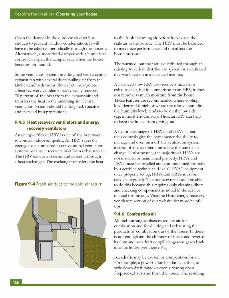
Open the damper in the outdoor-air duct just enough to prevent window condensation. It will have to be adjusted periodically through the seasons. Alternatively, a motorized damper with a humidistat control can open the damper only when the house becomes too humid.
Some ventilation systems are designed with a central exhaust fan with several ducts pulling air from the kitchen and bathrooms. Better yet, incorporate a heat recovery ventilator that typically recovers 70 percent of the heat from the exhaust air and transfers the heat to the incoming air. Central ventilation systems should be designed, specified and installed by a professional.
9 .4 .5 Heatrecoveryventilatorsandenergyrecoveryventilators
An energy-efficient HRV is one of the best ways to control indoor air quality. An HRV saves on energy costs compared to conventional ventilation systems because it recovers heat from exhausted air. The HRV exhausts stale air and passes it through a heat exchanger. The exchanger transfers the heat
to the fresh incoming air before it exhausts the stale air to the outside. The HRV must be balanced to maximize performance and not affect the house pressure.
The warmed, outdoor air is distributed through an existing forced-air distribution system or a dedicated ductwork system in a balanced manner.
A balanced-flow ERV also recovers heat from exhausted air, but in comparison to an HRV, it does not remove as much moisture from the house. These features are recommended where cooling load demand is high or where the relative humidity (i.e. humidity level) tends to be on the low side (e.g. in northern Canada). Thus, an ERV can help to keep the house from drying out.
A major advantage of HRVs and ERVs is that their controls give the homeowner the ability to manage and even turn off the ventilation system instead of the weather controlling the rate of air change. Unfortunately, the majority of HRVs are not installed or maintained properly. HRVs and ERVs must be installed and commissioned properly by a certified technician. Like all HVAC equipment, once properly set up, HRVs and ERVs must be serviced regularly. The homeowner should be able to do this because this requires only cleaning filters and checking components as noted in the service manual for the unit. Visit the Heat/energy recovery ventilators section of our website for more helpful tips.
9 .4 .6 CombustionairAll fuel-burning appliances require air for combustion and for diluting and exhausting the products of combustion out of the house. If there is not enough air, the chimney or flue could reverse its flow and backdraft or spill dangerous gases back into the house (see Figure 9-5).
Backdrafts may be caused by competition for air. For example, a powerful kitchen fan, a barbeque-style down draft range or even a roaring open fireplace exhausts air from the house. The resulting
Figure9-4 Fresh-air duct to the cold-air return
Keeping the Heat In ● Operating your house
126

negative pressure can pull air into the house down chimneys or vents.
Signs of combustion air problems include
• back-puffing of the furnace, boiler or water heater (indicated by soot or staining around the air intake, burner, barometric hood, damper or chimney connections), or melted plastic fittings on top of the tank-type water heater
• unusual odours or hot and muggy air around or from the combustion appliance
• difficulty starting or maintaining a fire in the fireplace
• occupants experiencing frequent headaches, skin or throat irritations or nausea
The first line of defence is to replace spillage-susceptible space and DWH equipment with direct vent or sealed combustion appliances. For example, electricity, or better yet, consider heat pump technologies.
Figure9-5 Many appliances compete for household air
Keeping the Heat In ● Operating your house
127

Conventional open fireplaces can be a wonderful feature of a home, but they are also responsible for leaking heated air to the outside and are prone to backdrafting. When at the end of their burn cycles, fireplaces release large quantities of carbon monoxide and are also more vulnerable to backdrafting at this point. Minimize this problem by installing tight-fitting glass doors and consider opening a window slightly when you operate the fireplace.
9 .5 MOREWAYSTOSAVEENERGY
Explore the Energy efficiency renovations section of our website to access a wealth of additional tips on saving energy in your home and to learn more about how an EnerGuide home evaluation can help you make informed decisions when operating, renovating or purchasing a home.
SAFETYWARNING:Always install CO detectors in a home that has combustion appliances (fireplace, wood stove, fuel-burning furnace or water heater) or an attached garage. Properly installed, these detectors will help protect occupants from asphyxiation caused by a venting failure or malfunction of combustion appliances or automobile fumes leaking into the home from an attached garage. Never operate a vehicle in an enclosed space. Always open the garage door before starting a car inside.
Regularly replace batteries in CO and smoke detectors. These devices have limited life spans and must be replaced regularly. Check the manufacturer’s literature for this information.
Figure9-6 Direct-venting heating equipment
Keeping the Heat In ● Operating your house
128

Keeping the Heat In
Index
1/3 – 2/3 rule (see one-third, two-thirds rule)
additions . . . . . . . . . . . . . . . . . . . . . . . . . . . . . . . . . 108
air barriers
general . . . . . . . . . . . . . . . . . . . . . . . . . . . . . . . . . 15
materials . . . . . . . . . . . . . . . . . . . . . . . . . . . . 29-39
air leakage control
attics . . . . . . . . . . . . . . . . . . . . . . . . . . . . 44, 49-50
attic hatches . . . . . . . . . . . . . . . . . . . . . . . . . . . . 48
basements . . . . . . . . . . . . . . . . . . . . . . . . . . . . . . 90
cathedral ceilings . . . . . . . . . . . . . . . . . . . . . 64-65
chimneys . . . . . . . . . . . . . . . . . . . . . . . . . . . . 52-53
detection of air leaks . . . . . . . . . . . . . . . . . . . . . 42
doors . . . . . . . . . . . . . . . . . . . . . . . . . . . . . 117-118
electrical outlets . . . . . . . . . . . . . . . . . . . . . . . . . 46
exposed floors . . . . . . . . . . . . . . . . . . . . . . . . . . 94
fireplaces . . . . . . . . . . . . . . . . . . . . . . . . . . . . . . . 47
fixtures . . . . . . . . . . . . . . . . . . . . . . . . . . . . . . . . 56
flat roofs . . . . . . . . . . . . . . . . . . . . . . . . . . . . . . . 65
floors . . . . . . . . . . . . . . . . . . . . . . . . . . . . . . . . . . 94
garages . . . . . . . . . . . . . . . . . . . . . . . . . . . . . . . 107
general . . . . . . . . . . . . . . . . . . . . . . . . . . . . . . 41-44
header area . . . . . . . . . . . . . . . . . . . . . . . . . . 89-92
overhangs . . . . . . . . . . . . . . . . . . . . . . . . . . . . . . 94
trim areas . . . . . . . . . . . . . . . . . . . . . . . . . . . . . . 46
walls . . . . . . . . . . . . . . . . . . . . . . . . . . . . . . . 98-109
windows . . . . . . . . . . . . . . . . . . . . . . . 42, 112-115
wiring . . . . . . . . . . . . . . . . . . . . . . . . . . . . . . 52-56
air sealing (see air leakage control)
air and vapour barriers . . . . . . . . . . . . . 15-16, 40, 51
attics . . . . . . . . . . . . . . . . . . . . . . . . . . . . . . . . . . 49-66
attic hatches . . . . . . . . . . . . . . . . . . . . . . . . . . . . . . . 48
backdraft . . . . . . . . . . . . . . . . . . . . . . . . . . . . . . . . 126
backer rod (foam rope) . . . . . . . . . . . . . . . . . . . . . . 35
baffles . . . . . . . . . . . . . . . . . . . . . . . . . . . . . . . . . . . . 59
basements . . . . . . . . . . . . . . . . . . . . . . . . . . . . . . 72-94
bonus room . . . . . . . . . . . . . . . . . . . . . . . . . . . . . . 107
building codes (see codes and standards)
cathedral ceilings . . . . . . . . . . . . . . . . . . . . . 64-65, 68
caulking . . . . . . . . . . . . . . . . . . . . . . . .8, 30-35, 44-45
ceiling hatch (see attic hatches)
chimneys . . . . . . . . . . . . . . . . . . . . . . . . . . . . . . . 52-53
codes and standards . . . . . . . . . . . . . . . . . . . . . . . . . 4
cold cellar . . . . . . . . . . . . . . . . . . . . . . . . . . . . . . 81, 93
combustion air . . . . . . . . . . . . . . . . . . . . 122, 126-127
common wall . . . . . . . . . . . . . . . . . . . . . . . . . . . . . . 99
condensation (see moisture problems)
129

contract . . . . . . . . . . . . . . . . . . . . . . . . . . . . . . . . . . . . 5
cooling systems . . . . . . . . . . . . . . . . . . . . . . . . . . . 122
crawl spaces . . . . . . . . . . . . . . . . . . . . . . . . . . . . 94-96
crib (see attic hatches)
damp-proofing (see also waterproofing)
domestic water heater . . . . . . . . . . . . . . . . . . . . . . 122
doors . . . . . . . . . . . . . . . . . . . . . . . . . . . . . . . . 117-118
dormer windows . . . . . . . . . . . . . . . . . . . . . . . . . . . 64
drainage plane . . . . . . . . . . . . . . . . . . . . . . . . . . . . . 16
dropped ceiling . . . . . . . . . . . . . . . . . . . . . . . . . . . . 69
DWH (see domestic water heater)
efflorescence . . . . . . . . . . . . . . . . . . . . . . . . . . . 74-75
electrical outlets . . . . . . . . . . . . . . . . . . . . . . 42-43, 46
energy recovery ventilator . . . . . . . . . . . . . . 125-126
ENERGY STAR® . . . . . . . . . 110, 118, 120, 122, 125
EPS (expanded polystyrene) . . . . . . . . . . . . . . . . . . 25
ERV (see energy recovery ventilator)
exposed floors . . . . . . . . . . . . . . . . . . . . . . . . . . . . . 97
fireplaces . . . . . . . . . . . . . . . . . . 42, 47, 121, 123, 128
fire resistance . . . . . . . . . . . . . . . . . . . . . . . . . . . . . . 22
fire stops . . . . . . . . . . . . . . . . . . . . . . . . . . . . . . 99, 101
flashing . . . . . . . . . . . . . . . . . . . . . . . . . . . . . 76-77, 79
flat roofs . . . . . . . . . . . . . . . . . . . . . . . . . . . . . . . 64-65
frost heave . . . . . . . . . . . . . . . . . . . . . . . . . . 82, 95, 96
garages . . . . . . . . . . . . . . . . . . . . . . . . . . . . . . . . . . 107
gaskets . . . . . . . . . . . . . . . . . . . . . . . . . . . . . . . . . . . 35
half storeys . . . . . . . . . . . . . . . . . . . . . . . . . . . . . . . . 62
health and safety
equipment . . . . . . . . . . . . . . . . . . . . . . . 4, 5, 22, 24
UFFI and asbestos . . . . . . . . . . . . . . . . . . . 5, 6, 22
vermiculite . . . . . . . . . . . . . . . . . . . . . . 5, 6, 28, 51
heat recovery ventilator . . . . . . . . . . . . . . . . . 125, 126
heating system . . . . . . . . . . . . . . . . . . . . . 13, 119-121
heating, ventilating and air conditioning . . . . . . . 119
hiring a contractor . . . . . . . . . . . . . . . . . . . . . . . 5, 113
hot roof . . . . . . . . . . . . . . . . . . . . . . . . . . . . . . . 64-65
house as a system . . . . . . . . . . . . . . . . . . . . . . . . . 4, 13
HRV (see heat recovery ventilator)
humidity (see moisture)
HVAC (see heating, ventilating and air conditioning)
ice dams . . . . . . . . . . . . . . . . . . . . . . . . . . . . . . . 66-68
indoor air quality . . . . . . . . . . . . . . . 22, 121, 122-126
insulation
attics . . . . . . . . . . . . . . . . . . . . . . . . . . . . 50, 59-61
basements . . . . . . . . . . . . . . . . . . . . . . . . . . . 76-97
compression . . . . . . . . . . . . . . . . . . . . . . . . . . . . 37
concrete slab . . . . . . . . . . . . . . . . . . . . . . . . . . . . 97
crawl spaces . . . . . . . . . . . . . . . . . . . . . . . . . 94-95
dense-pack . . . . . . . . .25, 62, 64, 65, 68, 100, 107
general . . . . . . . . . . . . . . . . . . . . . . . . . . . . . . . . .7-8
half storeys . . . . . . . . . . . . . . . . . . . . . . . . . . . . . 62
Keeping the Heat In ● Index
130

knee walls . . . . . . . . . . . . . . . . . . . . . . . . . . . . . . 62
materials . . . . . . . . . . . . . . . . . . . . . . . . . . . . 21-40
open foundations . . . . . . . . . . . . . . . . . . . . . . . . 97
prohibited . . . . . . . . . . . . . . . . . . . . . . . . . . . . . . 22
radiant foils . . . . . . . . . . . . . . . . . . . . . . . . . . . . . 27
regulated . . . . . . . . . . . . . . . . . . . . . . . . . . . . . . . 22
roof . . . . . . . . . . . . . . . . . . . . . . . . . . . . . . . . 70-71
walls . . . . . . . . . . . . . . . . . . . . . . . . . . . . . . . . . . 100
moisture
attics . . . . . . . . . . . . . . . . . . . . . . . . . . . . . . . 50-51
barrier (see moisture – moisture barrier, vapour barriers)
basements . . . . . . . . . . . . . . . . . . . . . . . . . . . 77-78
crawl spaces . . . . . . . . . . . . . . . . . . . . . . . . . 94-95
general . . . . . . . . . . . . . . . . .11-12, 17-18, 119-121
moisture barrier . . . . . . . . . . . . . . . . . . . 19-20, 40
sources . . . . . . . . . . . . . . . . . . . . . . . . . 17-18, 119
walls . . . . . . . . . . . . . . . . . . . . . . . . . . . . . . . . . . 100
windows . . . . . . . . . . . . . . . . . . . . . . . . . . . . . . 112
moisture problems . . . . . . . . . . . . . . . . . . . . . . . . 124
mould . . . . . . . . . . . . . . . . . . . . . . . . . . . . . . . . . . . . . 6
new construction . . . . . . . . . . . . . . . . . . . . . . . . . . 108
one-third, two-thirds rule . . . . . . . . . . . . . . . . . . . . 19
open foundations . . . . . . . . . . . . . . . . . . . . . . . . . . 97
oriented strand board . . . . . . . . . . . . . . . . . . . . 16, 45
OSB (see oriented strand board)
overhangs . . . . . . . . . . . . . . . . . . . . . . . . . . . . . . . . . 93
parging . . . . . . . . . . . . . . . . . . . . . . . . . . . . . . . . 79-80
party wall . . . . . . . . . . . . . . . . . . . . . . . . . . . . . . . . . 99
patio doors (see doors)
permits . . . . . . . . . . . . . . . . . . . . . . . . . . . . . . . . . . . . 4
quotes . . . . . . . . . . . . . . . . . . . . . . . . . . . . . . . . . . . . . 5
radiant insulation products (see insulation – radiant foils)
radon . . . . . . . . . . . . . . . . . . . . . . . . . . . . . . . . . 6-7, 74
recessed light fixtures . . . . . . . . . . . . . . 56, 61, 65, 70
roof . . . . . . . . . . . . . . . . . . . . . . . . . . . . . . . . . . . 49-71
sealants (see caulking)
smart retarder (see vapour barriers)
stack effect . . . . . . . . . . . . . . . . . . . . . . . . . . . . . . . . 11
thermal bridging . . . . . . . . . . . . . . . . . . . . . . . . . . . 14
UFFI . . . . . . . . . . . . . . . . . . . . . . . . . . . . . . . . . 22, 133
vapour barriers . . . . . . . . . . . . . . . . . . . . . . . 15-20, 40
ventilation
attics . . . . . . . . . . . . . . . . . . . . . . . . . . . . 50-51, 57
combustion air . . . . . . . . . . . . . . . . . . . . . 122-123
crawl spaces . . . . . . . . . . . . . . . . . . . . . . . . . 94-95
house . . . . . . . . . . . . . . . . . . . . . . . .15-17, 122-126
vermiculite . . . . . . . . . . . . . . . . . . . . . . . . . . . 6, 28, 51
water heating (see domestic water heater)
waterproofing (see also damp-proofing) . . . . . . 73-74
weather barrier . . . . . . . . . . . . . . . . . . . . . . . . . . 15-17
weatherstripping . . . . . .36-38, 48, 113-115, 117-118
wind barrier (see weather barrier)
Keeping the Heat In ● Index
131

windows
insulation . . . . . . . . . . . . . . . . . . . . . . . . . . . . . 117
new windows . . . . . . . . . . . . . . . . . . . . . . 112, 117
retrofit . . . . . . . . . . . . . . . . . . . . . . . . . . . . 110-115
storm windows . . . . . . . . . . . . . . . . . . . . . 115-116
wiring
upgrading wiring . . . . . . . . . . . . . . . . . . . . . . . . . 3
XPS (extruded polystyrene) . . . . . . . . . . . . . . . . . . 26
Keeping the Heat In ● Index
132


Natural Resources Canada’s Office of Energy Efficiency Leading Canadians to Energy Efficiency at Home, at Work and on the Road