keeping centrifugal pump trouble free and energy …
TRANSCRIPT

KEEPING CENTRIFUGAL PUMP TROUBLEFREE AND ENERGY SAVING TIPS

LIBRARY IRCPO Box 93190,2509 AD THE HAGUE
Tel.: +31 70 30 689 80Fax: +31 70 35 899 64
BARCODE:LO:
' • E
l f 0
XAkraryIRC in^mMlonalVvateand Sanitation CentreT«.:+31 70 30 689 80Fax: +31 70 38 899 64
DO IT YOURSELF
KEEPING CENTRIFUGAL PUMPTROUBLE FREE & ENERGY
SAVING TIPSSyed Anis Ahmad*
1.0 Introduction :
In the past few years, there has been significant achieve-ment in the development of ground water resource involvingincrease in the number of irrigation pumping sets. Theincrease in pumping sets has like-wise been affected through-out the country. However, comparable facilities for properrepair and maintenance have so far been lacking. It may notbe possible for the users to take up major repairs by them-selves but usual maintenance, proper handling and minorrepairs can be performed by them knowing schedule of main-tenance, possible trouble and their remedies. A properlymaintained pumping set gives trouble free operation and lowoperating cost.
The pumping sets commonly used are centrifugal pumpsdriven by diesel engine or electric motor. A break down of
*Sr. Lecturer, Deptt. of Renewable Source of Energy,I. E. R. T.s Alld.

the pump during the irrigation season could mean a greatreduction in yield and farm income. Therefore, it is necessaryto ensure proper care and maintenance of centrifugal pumpsfor their efficient and prolonged service.
2.0. About the Centrifugal Pump :
1. Casing 2. Vane5. Discharge
3. Eye of Impeller 4, Impeller Shaft
Fig. i
A centrifugal pump is a rotary machine consisting of twobasic parts, the rotary element or impeller and the stationaryelement or casing (Fig. 1). The impeller is a wheel or discmounted on a shaft and provided with a number of vanes orblades usually curved. The vanes are arranged in a circular
( 2 )

array around an inlet opening at the centre. The impelleris secured on a shaft mounted on suitable bearing, Theshaft usually has a stuffing box or seal where it passes throughthe casing wall. Stuffing box packings are generally madeof basic materials such as asbestos or organic fibre.
3.0. Care Prior to Starting Pump :Prior to starting the pump for the first time special atten-
tion should be paid to the following points :—
t. Check the alignment of the pump. (See fig. 2).
4
1. Steel straight edge4. Thickness gauge.
Fig. 2 (a)—Incorrect Alignment
2. Pump shaft 3. Couplings
Fig. 2 (b)—Correct AlignmentFig. 2 (a & b) checking of pump alignment

2.
The pump and primemover (driver) must be carefullyaligned. The correct method of aligning couplings isshown in above fig. 2. Parallel alignment can be checkedby placing a straight edge across the coupling halves.They must raise evenly on both halves at four positionsplaced at approximately 90° intervals around thecoupling, Angular alignment can be checked witha feeler gauge placed between the coupling halvesat 4 points around the coupling.
Make sure that the engine/motor will drive the pumpin the direction indicated on the pump body (FollowFig. 3).
t . Pump 2. Coupling 3. Primemover 4. Foot Valve.
Fig. 3—Correct direction of Rotation

3. Make sure that the gland is lightly and evenly adjustedand the pump shaft revolves freely when turned byhand, (Follow Fig. 4).
1. Pump 2. Coupling 3. Pritnemover 4. Gland packinglightly and evenly adjusted/tighten 5, Foot Valve
Fig. 4
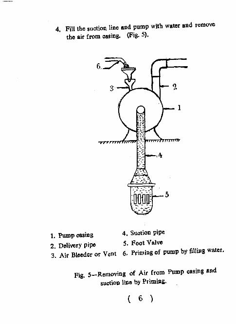
4. Fill the suction line and pump with water and removethe air from casing. (Fig. 5).
1. Pump casing 4. Suction pipe
2. Delivery Pipe 5. Foot Valve3. Air Bleeder or Vent 6. Priming of pump by filling water.
Fig. 5-Removing of Air from Pump casing andsuction line by Priming.

5. Check the air tightness of the suction pipe and anyleakage in the foot valve. (Fig. 6).
1. Coupling2. Vent3. Airtight flanges4. Water leakage5. Suction pipe
6. Water leakage7. Foot valve8. Delivery pipe9. Water.
Fig. 6
( 7

After fitting the airtight flanges and foot valve in thesuction line as shown in Fig. 6, fill the pump body and itssuction pipe completely with water and leave the system forfew minutes If there is any air leakage in flanges and footvalve joints the filled water will flow in drops. Dismantle allthe joints, clean the surfaces, place the mbber packing in bet-ween flanges joint, coat the white lead over the threaded por-tion and then tighten all the joints carefully. For foot valvecheck seat and packing and repair it. Insert the foot valveproperly in the suction line and tighten the pipe and make acoat of while lead over the joint,
6. Attend to lubrication requ'u emeots whertver necessary.
4.0 Pump Operation :
On account of its simple construction, the centrifugalpump requires practically no attention while running. Properlubrication of the bearing and adjustment of the glands areusually the only things which need attention from the operator.The centrifugal pump must be stopped promptly if no liquid isbeing pumped.
5.0. Pomp Maintenance :
Operating conditions of pumps vary widely and so do themaintenance requirements. There are some tips, that shouldbe kept in mind for the successful operation and maintenanceof a centrifugal pump. The following maintenance schedulesapply to most pumps under average operating conditions:—
( 8 )

5,1. General:
(i) The pump and engine/motor flanges should be in align-ment.
(ii) The entire suction and discharge Hoe should be self-supporting. No weight from the piping should be puton tbe pumps otherwise the casing is likely to becraoked or damaged.
(iii) Use a suitable foot valve at the entrance of the suctionpipe when it is planned to pump from an open pit.
(iv) Gland packing should be replaced periodically. Neverput a new packing on the old one.
(v) Never tighten a gland more than necessary. After therequired number of rings have been inserted, theyshould first be tightened until there is no leakage.(F.g-4).
(vi) Replace the worn out rubber flap of the foot valve.
(vii) Never run pump dry. If pump runs dry, the rota-ting parts will wear out quickly. In case the prime-mover is to be started, it should be disconnected fromthe pump.
(VIM) Coat all the piping joints with white lead.
(ix) Lubricate the bearings with grease of proper grade.Clean the nipple and the connector before lubrication.It should be done while the pump is running.

5.2. Every Month :
Check bearing temperature. Bearings may run hot dueto lack of lubrication or excess lubricants
5.3. Every Three Month :
Drain lubricants in ring oil bearings and wash out oilwells and bearings with kerosene. In case of sleeve bearings,check to see that oil rings are free to turn with the shaft.Refill with the lubricant recommended by the manufacturer.Check the wear in the bearings and replace, if excessive.
5.4. Every Six Month :
Replace gland packing. Check alignment of pump anddriver and add shims if required.
5.5. Every Year :
Thoroughly inspect the unit once a year. Remove bear-ings, clean and examine for flaws. Clean bearing housings.Remove packing and examine the wear in the shaft sleeve orshaft. Disconnect coupling and check alignment. Inspectfoot valve and check valves.
6.0. Spare Parts :
It is advisable that following spares be maintained by theowner for quick replacement and smooth operation of thepump.
C 10 )

(i) Set of ball bearings,
(ii) Coupling bolts with washer.
(Hi) Rubber packing,
(iv) Gland packings.
7.0. Pomp Troubles, Causes and Their Remedies :
When the centrifugal pump fails to operate or there is re-duction in discharge or pressure drops, the cause of troubleshould be investigated and steps taken to eliminate it. A listof the most common troubles, causes and their remedies aregiven below :—
, S. No. Troubles & Causes Remedies
1 2 3
A. Pump not Delivered water at First Start
(i) Lack of Priming (i) Fill the pump and its sue
tion pipe completely withwater. Leave the ventsopen until clear bubblefree liquid flows from them.Close tbe vents and startthe pump.
(ii) Speed of pump driver (ii) Adjust the driver speed totoo low. its proper speed.
( 11 )

(iii) Discharge head too (iii) Check vertical head (parti-high cularly friction loss).
(iv) Suction lift too high (iv) (a) Total lift including fric-tion loss in suction pipeshould not exceed 7.5meters.
(b) Check the foot valvestrainer choking.
(v) Wrong direction of rota- (v) Cheok up the pump turnstion in the direction of arrow.
(vi) Air leaks in gland (vi) Tighten the gland,
(vii) Air leaks in suction pipe (vii) Tighten the suction pipe.
(viii) Water leaks through (viii) Cheok up the foot valve,foot valve.
B. Not Enough Water Delivered
(i) Speed too low (i) Adjust to its proper speed.
(it) Impeller eye too small (ii) Install the pump having asuitable capacity for thejob.
( 12 )

(tit) Discharge head higher (iii) Check particularly frictionthan anticipated. loss.
(iv) Atr pocket in suction (iv) Remove air pocket by fill-line, ing the pump and suction
pipe completely by water.
(v) Impeller or suction (v) Removo the foreign matterpipe plugged up. causing plugging.
(vi) Air leakage. (vi) Check the pump stuffingboxes and adjust the gland.
(vii) Foot valve too small (vii) Replace with the suitable footvalve.
(viii) Mechanical defects : (viii) Remove mechanical defects.
(a) Wearing rings worn out (a) Replace all worn out partsduring the pump overhaul.
(b) Impeller damaged (b) Repair or replace the damagedimpeller.
(c) Casing packing defective (c) Make the casing packing pro-perly effective.
( 13 )

C. Low Discharge Pressure Developed :
(i) Speed too low (i) Adjust suitable speed.
(ii) Worn wearing rings, (ii) Replace the wornout parts,packing, gasket etc.
(iii) Damaged Impeller (iii) Repair or replace the damagedimpeller.
(iv) Pump water passage (iv) Remove any obstructions in theobstructed. passage.
(v) Excessive amount of air (v) Remove if possible or wait tillor gas in liquid. the air or gas exhausted.
(vi) Impeller diameter too (vi) Check with the pump manu-
small. facturer.
D. Pump Stops Delivering Water While Working ;
(i) Air leaks through the (i) Tighten the gland,gland.
(ii) Air leaks through the (ii) Locate the leak and removeflange or some joint in the cause of leak,the suction line.
(iii) Impeller is choked up (iii) Remove the foreign matter.with foreign matter.
(iv) Foot valve strainer oho- (iv) Clean the foot valve,
ked up with rubbish.

(v) Water level gone down (v) Wait till the water rises orbelow practical suction lower the pump within thelift. practical suction lift.
(vi) Engine is running slow (vi) Adjust the engine to its pro-per speed.
(vii) Belt is slipping, if driven (vii) Tighten the belt,by belt.
E. Pump is Noisy :
(i) Bearing worn out (i) Check and replace.
(ii) Pump and driving units (ii) Make the proper alignmentmisaligned. of pumps and driving unit.
(iii) Rotating parts out of (iii) Check and repair,balance, loose or broken.
(vi) Foundation is not rigid (iv) Use correct foundation forrigidity.
(v) Lack of lubrication (v) Lubricate the moving parts.
F. Pump Takes too Much Power
(i) The bearings are (0 (a) Check the lubrication isrunning hot, properly given.
(b) Check that the belt is notover tight.

1
(ii) Speed too high (ii) Adjust the speed suitably.
(iii) Vibration in pump (iii) (a) Use correct foundation forrigidity.
(b) Check for pump misalign-ment,
(c) Check for bent shaft,
(iv) Stuffing box too tight (iv) Adjust the tightness.
(v) Rotating element rubb- (v) Check and repair the rubbinging parts.
G. Pump does not Start
(i) Impeller looked (i) Remove the sand or any othercause of locking,
(ii) Trash in casing (ii) Remove the obstruction and fitthe suction with strainer tokeep trash out of the pump.
(iii) Corrosion in case of (iii) Remove the corroded matterpumps out of service from the pump by using acidfor long period. or other recommended chemi-
cals.
(iv) Too much beariDg fric- (iv) Use the right lubricating oiltion and check the shaft bent, rep-
lace if necessary.
(v) Wiring faulty, if driven (v) Check the circuit breaker ofby electric motor. fuses for an open Hoe.

ENERGY SAVING TIPS FOR FARMERS
Which foot-valve saves more energy ?
The foot-valve in the diagram A has a wider mouth andlarger area of openings. This helps save about 10 percentenergy (diesel/electricity) because less fuel or less power isseeded to draw water from the well (A good foot-valve,though slightly costlier, pays back fast for the extra cost bysaving a lot of energy). The recommended foot valve shouldhave K valve which is less than 0.8 mm.
Which pipeline requires lesser quantity of diesel ?
The pipeline, with bigger diameter figure B requires lessenergy. More energy is required to pump water-through smalldiameter pipes because they offer higher friction. If the pipeis bigger than the pump flange size, a reducer (see the figure)must be used. A 20 mm decrease in diameter increases thefriction 3 times. If, in place of a 100 mm (4") pipe, you use80 mm (3") pipe, the loss due to friction for drawing the samequantity of water will be three times more, and your energyconsumption greater.
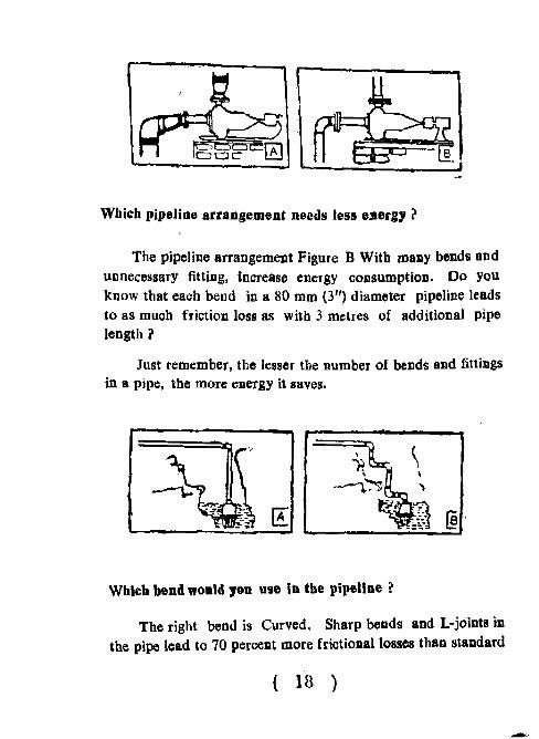
Wbich pipeline arrangement needs less energy ?
The pipeline arrangement Figure B With many bends andunnecessary fitting, increase energy consumption. Do youknow that each bend in a 80 mm (3") diameter pipeline leadsto as much friction loss as with 3 metres of additional pipelength ?
Just remember, the lesser tbe number of bends and fittingsin a pipe, the more energy it saves.
Which bend would you use in the pipeline ?
The right bend is Curved, Sharp bends and L-jolnts inthe pipe lead to 70 percent more frictional losses than standard
( 18 )
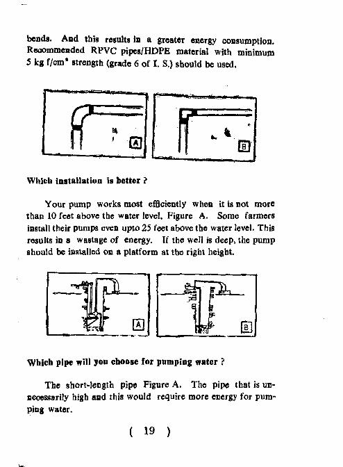
bends. And this results in a greater energy consumption.Recommended RPVC pipes/HDPE material with minimum5 kg f/cm* strength (grade 6 of I. S.) should be used.
Which installation is better ?
Your pump works most efficiently when it is not morethan 10 feet above the water level, Figure A. Some farmersinstall their pumps even upto 25 feet above the water level. Thisresults in a wastage of energy. If the well is deep, the pumpshould be installed on a platform at the right height.
Which pipe will you choose for pumping water ?
The short-length pipe Figure A. The pipe that is un-necessarily high and this would require more energy for pum-ping water.
( 19 )

I
/
•1
1 T— =i—rrr*C ^ " cLg.
Which transmission is better ?
The transmission shown in the Figure A. The belt in thesecond pioture is old and worn out. It can slip or snap any-time, causing a loss in the transmission of power and hence anincreased energy consumption.
( 20 )

IERT-CDRT-ISD-DIYS-12
This work was carried outwith the aid of a grant fromInternational Development ResearchCentre, Ottawa, Canada.
EDITOR :
P. P. Lahiry
For more details contact:
Information Service DivisionCentre for Development of Rural TechnologyInstitute of Engg. & Rural Technology26, Chatham Lines, Allahabad-2U002.