kdb-fa fc st stg - saturn s.a. · the diagram of the standard piping : cistern tank install type...
TRANSCRIPT
1
Thank you for using our KYUNG-DONG NAVIEN. To use this boiler in the proper way, be sure to read this manual fully before using it, and keep this manual with the warranty of the quality in a safe place.
1. The structure and its description ------------------------- 2 2. How to install ------------------------------------------- 13
3. Before using the boiler ---------------------------------- 16
4. How to use -------------------------------------------- 19
5. Safety device ------------------------------------------- 22
6. Everyday checking ------------------------------------- 23
7. How to replace parts ------------------------------------ 26
8. How to locate a troubles and to salve -------------------- 27
9. The specification ---------------------------------------- 28
10. Electric wiring diagram ----------------------------------- 30
11. After sales service
CONTENTS
2
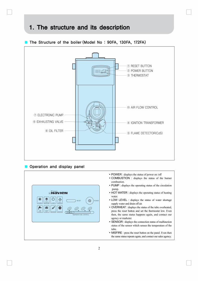
■ The Structure of the boiler (Model No : 90FA, 130FA, 172FA)
■ Operation and display panel
POWER : displays the status of power on /off COMBUSTION : displays the status of the burner combustion.
PUMP : displays the operating status of the circulation pump.
HOT WATER : displays the operating status of heating water.
LOW LEVEL : displays the status of water shortage supply water and drain off air.
OVERHEAT : displays the status of the tube overheated, press the reset button and set the thermostat low. Even then, the same status happens again, and contact our agency or marketer.
SENSOR : displays the connection status of malfunction status of the sensor which senses the temperature of the tube.
MISFIRE : press the reset button on the panel. Even then the same status repeats again, and contact our sales agency.
1. The structure and its description
3
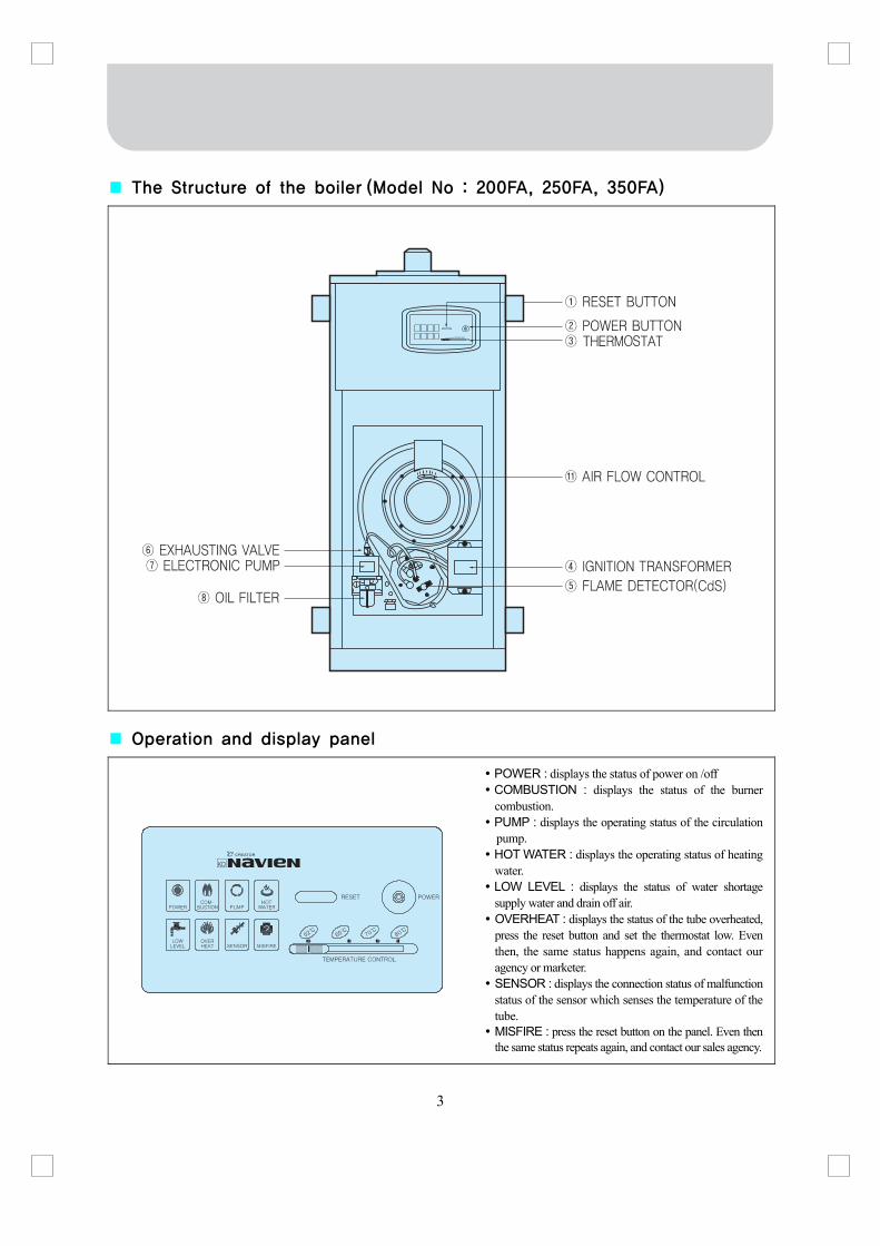
■ The Structure of the boiler (Model No : 200FA, 250FA, 350FA)
■ Operation and display panel
POWER : displays the status of power on /off COMBUSTION : displays the status of the burner combustion.
PUMP : displays the operating status of the circulation pump.
HOT WATER : displays the operating status of heating water.
LOW LEVEL : displays the status of water shortage supply water and drain off air.
OVERHEAT : displays the status of the tube overheated, press the reset button and set the thermostat low. Even then, the same status happens again, and contact our agency or marketer.
SENSOR : displays the connection status of malfunction status of the sensor which senses the temperature of the tube.
MISFIRE : press the reset button on the panel. Even then the same status repeats again, and contact our sales agency.

4
■ The Structure of the boiler (Model No : 253STG)
■ Operation and display panel
POWER : displays the status of power on /off COMBUSTION : displays the status of the burner combustion.
PUMP : displays the operating status of the circulation pump.
LOW LEVEL : displays the status of water shortage supply water and drain off air.
OVERHEAT : displays the status of the tube overheated, press the reset button and set the thermostat low. Even then, the same status happens again, and contact our agency or marketer.
SENSOR : displays the connection status of malfunction status of the sensor which senses the temperature of the tube.
MISFIRE : press the reset button on the panel. Even then the same status repeats again, and contact our sales agency.
5
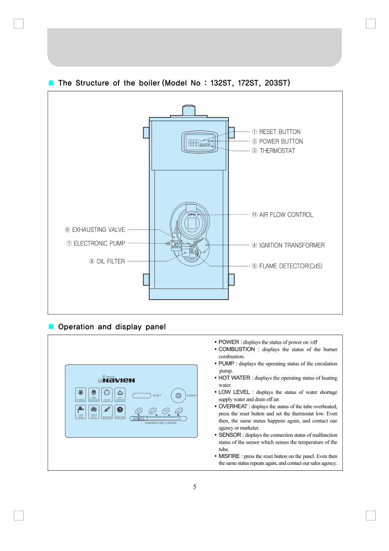
■ The Structure of the boiler (Model No : 132ST, 172ST, 203ST)
■ Operation and display panel
POWER : displays the status of power on /off COMBUSTION : displays the status of the burner combustion.
PUMP : displays the operating status of the circulation pump.
HOT WATER : displays the operating status of heating water.
LOW LEVEL : displays the status of water shortage supply water and drain off air.
OVERHEAT : displays the status of the tube overheated, press the reset button and set the thermostat low. Even then, the same status happens again, and contact our agency or marketer.
SENSOR : displays the connection status of malfunction status of the sensor which senses the temperature of the tube.
MISFIRE : press the reset button on the panel. Even then the same status repeats again, and contact our sales agency.

6
■ The Structure of the boiler (Model No : 253ST)
■ Operation and display panel
POWER : displays the status of power on /off COMBUSTION : displays the status of the burner combustion.
PUMP : displays the operating status of the circulation pump.
HOT WATER : displays the operating status of heating water.
LOW LEVEL : displays the status of water shortage supply water and drain off air.
OVERHEAT : displays the status of the tube overheated, press the reset button and set the thermostat low. Even then, the same status happens again, and contact our agency or marketer.
SENSOR : displays the connection status of malfunction status of the sensor which senses the temperature of the tube.
MISFIRE : press the reset button on the panel. Even then the same status repeats again, and contact our sales agency.
7
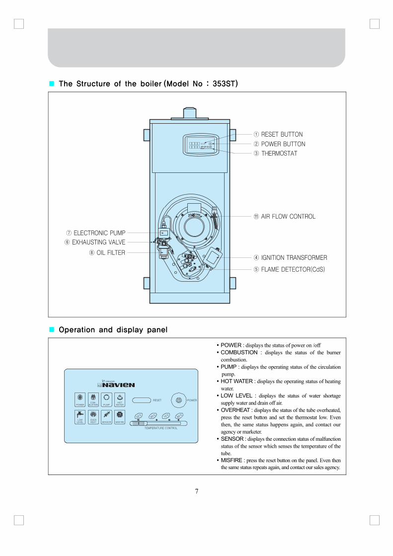
■ The Structure of the boiler (Model No : 353ST)
■ Operation and display panel
POWER : displays the status of power on /off COMBUSTION : displays the status of the burner combustion.
PUMP : displays the operating status of the circulation pump.
HOT WATER : displays the operating status of heating water.
LOW LEVEL : displays the status of water shortage supply water and drain off air.
OVERHEAT : displays the status of the tube overheated, press the reset button and set the thermostat low. Even then, the same status happens again, and contact our agency or marketer.
SENSOR : displays the connection status of malfunction status of the sensor which senses the temperature of the tube.
MISFIRE : press the reset button on the panel. Even then the same status repeats again, and contact our sales agency.

8
■ The Structure of the boiler (Model No : 134FC, 174FC)
■ The descriptions of the name
① RESET BUTTON : a switch for the restart when the “MISFIRE”, “OVERHEAT” lamp is on ② POWER BUTTON : a device for the boiler’s power on/off ③ THERMOSTAT : a device for controlling the temperature of the heating water. ④ IGNITION TRANSFORMER : a hight voltage generator(to ignite the burner) ⑤ FLAME DETECTOR : a device for identifying whether or not there is a flame in the fire box ⑥ EXHAUSTING VALVE : a device for removing air in fuel ⑦ ELECTRONIC PUMP : a device for spraying in fuel ⑧ OIL FILTER : a device for filtering impurities in fuel ⑨ CIRCULATION PUMP : a heating apparatus which circulates warm water ⑩ OPEN TYPE EXPANSION TANK : a device for absorbing the expanded water when the water in the pipes
of the boiler or a room is expanded. ⑪ AIR FLOW CONTROL : for the adjusting of airflow in the blower

9
■ The Structure of the boiler (Model No : 200FC)
■ The descriptions of the name
① RESET BUTTON : a switch for the restart when the “MISFIRE”, “OVERHEAT” lamp is on ② POWER BUTTON : a device for the boiler’s power on/off ③ THERMOSTAT : a device for controlling the temperature of the heating water. ④ IGNITION TRANSFORMER : a hight voltage generator(to ignite the burner) ⑤ FLAME DETECTOR : a device for identifying whether or not there is a flame in the fire box ⑥ EXHAUSTING VALVE : a device for removing air in fuel ⑦ ELECTRONIC PUMP : a device for spraying in fuel ⑧ OIL FILTER : a device for filtering impurities in fuel ⑨ CIRCULATION PUMP : a heating apparatus which circulates warm water ⑩ OPEN TYPE EXPANSION TANK : a device for absorbing the expanded water when the water in the pipes
of the boiler or a room is expanded. ⑪ AIR FLOW CONTROL : for the adjusting of airflow in the blower

10
■ Room controller(Model No : 90FA, 130FA, 134FC, 172FA, 174FC, 200FA, 200FA, 200FC, 250FA, 350FA, 132ST, 172ST, 203ST, 253ST, 353ST)
11
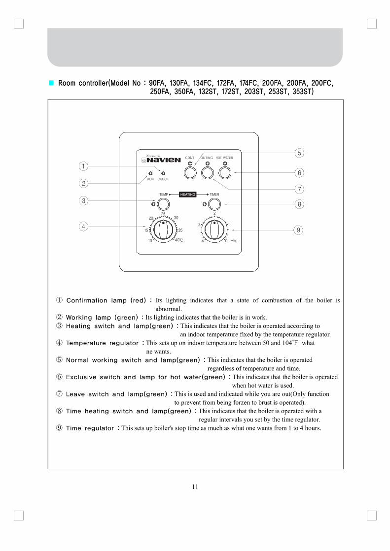
■ Room controller(Model No : 90FA, 130FA, 134FC, 172FA, 174FC, 200FA, 200FA, 200FC, 250FA, 350FA, 132ST, 172ST, 203ST, 253ST, 353ST)
① Confirmation lamp (red) : Its lighting indicates that a state of combustion of the boiler is
abnormal. ② Working lamp (green) : Its lighting indicates that the boiler is in work. ③ Heating switch and lamp(green) : This indicates that the boiler is operated according to
an indoor temperature fixed by the temperature regulator. ④ Temperature regulator : This sets up on indoor temperature between 50 and 104℉ what
ne wants. ⑤ Normal working switch and lamp(green) : This indicates that the boiler is operated
regardless of temperature and time. ⑥ Exclusive switch and lamp for hot water(green) : This indicates that the boiler is operated
when hot water is used. ⑦ Leave switch and lamp(green) : This is used and indicated while you are out(Only function
to prevent from being forzen to brust is operated). ⑧ Time heating switch and lamp(green) : This indicates that the boiler is operated with a
regular intervals you set by the time regulator. ⑨ Time regulator : This sets up boiler's stop time as much as what one wants from 1 to 4 hours.

12
■ Room controller(Model No. : 253STG)

13
■ Choosing of the installation place For the place to install the boiler, choose the place possible to do the accompanying works, such as water supply works or electric works.
For the place to install, choose the place conformed to the installation standards of the boiler and the construction act or the code of each city or municipality.
Install the boiler in the place as wide as possible for the maintenance and the fire prevention. Install the boiler in the place convenient for controlling and manipulation of the temperature. If there is no electric outlet in the proper position, do wiring by requesting to a company designated by the electric power company. Around the installation place, there must be no place which stores and treats the combustibles and the inflammables. There should be equiped drainage in the installing spot.
■ The diagram of the standard piping : Cistern tank install type(Model No. : 90FA,
130FA, 172FA, 200FA, 250FA, 350FA, 132ST, 172ST, 203ST, 253ST, 353ST) ■ The diagram of the standard piping : Open type tank installation type
(Model No. : 134FC, 174FC, 200FC)
2. How to install

14
■ The diagram of the standard piping : Cistern tank install type (Model No. : 253STG)
■ Precautions
① The distributor on the return water distributor side should be placed lower than the heating inlet.
② Connection should be made by installing a safety valve with 2.5kgf/cm2(ST·STG
model : 3.5kgf/cm2) or lower opening the discharge piping to the cistern tank.
③ The maximum operation pressure is 2.5kgf/cm2(ST·STG model : 3.5kgf/cm
2). Do not
supply water at a higher pressure or directly connect the water pipe heaving the pressure higher than 2.5kgf/cm
2(ST·STG model : 3.5kgf/cm
2).
④ Overflow of water during the heating to the cistern tank means short tank capacity. Exchange it with a larger one.
⑤ Backflow of water during the running or stopping of the circulation pump to the cistern tank is caused by too much air in the piping. Remove air by opening valves on the distributor, one at a time, while running the circulation pump.
⑥ Evaporation at the cistern tank means failure in the system. Contact your representative to receivethe check.
⑦ Never install any valve between the boiler and the cistern tank.
⑧ We will not be liable for any defect or breakdown caused by the failure to comply with the above precautions.
15
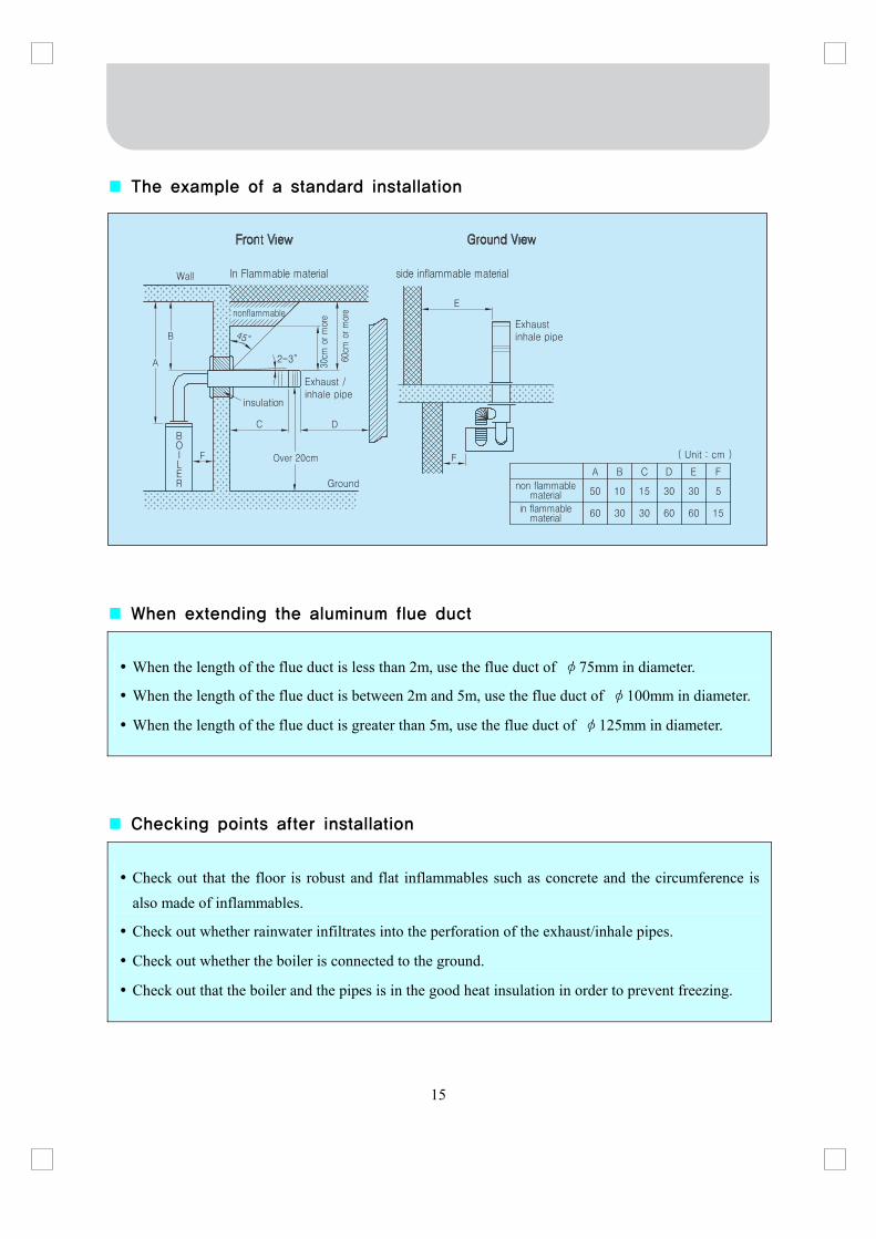
■ The example of a standard installation ■ When extending the aluminum flue duct
When the length of the flue duct is less than 2m, use the flue duct of φ75mm in diameter.
When the length of the flue duct is between 2m and 5m, use the flue duct of φ100mm in diameter.
When the length of the flue duct is greater than 5m, use the flue duct of φ125mm in diameter.
■ Checking points after installation
Check out that the floor is robust and flat inflammables such as concrete and the circumference is also made of inflammables.
Check out whether rainwater infiltrates into the perforation of the exhaust/inhale pipes.
Check out whether the boiler is connected to the ground.
Check out that the boiler and the pipes is in the good heat insulation in order to prevent freezing.
16
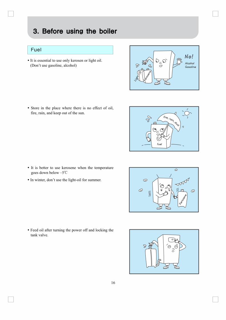
It is essential to use only kerosen or light oil. (Don’t use gasoline, alcohol)
Store in the place where there is no effect of oil, fire, rain, and keep out of the sun.
It is better to use kerosene when the temperature goes down below –5℃
In winter, don’t use the light-oil for summer.
Feed oil after turning the power off and locking the tank valve.
3. Before using the boiler
Fuel

17
Pay attention that water or dust may not get in on time of feeding oil.(Water or dust may cause the combustion failure or shorten the boiler span.)
Wipe off the oil spilled.
Close the lid of the oil inlet without fail.
Check out if or not oil leaks in the connecting part of the oil pipe.
Check out that there is enough water in the body of the boiler without failure.
Expansion tank type-Check out if there is water in the Expansion tank, and in case that there is no water, please fill water in the body of the boiler.
Open Expansion Tank type-check out if there is water in the expansion tank, and in case that there is no water, press the power button. Then, ‘Low Water Level’ lamp turns on and water is supplied automatically.
Checking points before starting up
18
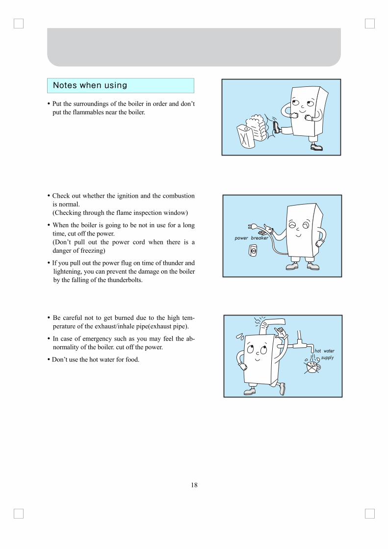
Put the surroundings of the boiler in order and don’t put the flammables near the boiler.
Check out whether the ignition and the combustion is normal. (Checking through the flame inspection window)
When the boiler is going to be not in use for a long time, cut off the power. (Don’t pull out the power cord when there is a danger of freezing)
If you pull out the power flug on time of thunder and lightening, you can prevent the damage on the boiler by the falling of the thunderbolts.
Be careful not to get burned due to the high tem-perature of the exhaust/inhale pipe(exhaust pipe).
In case of emergency such as you may feel the ab-normality of the boiler. cut off the power.
Don’t use the hot water for food.
Notes when using

19
Be careful that the oil tank may not run out of oil completely. In that case, even though oil is supplied, air may get in. As a result, ignition failure or operation failure may occurs.
Untighten the screw for exhaust in the oil filter by a screwdriver, the air goes out. When oil flows out, please tighten it. (This is possible only in case that the oil tank is above the oil filter)
If the oil tank is below the oil filter or the air flows out enough like the above, lock the screw for exhaust and remove the air with the exhaust valve.
In such case, open the exhaust valve turn the power on to operate the boiler. After about 6-7seconds, the electronic pump exhaust the air off with noise, and “MISFIRE” lamp on, the boiler stops.
4. How to use
How to exhaust
20
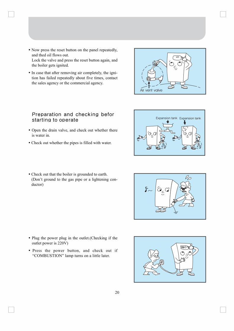
Now press the reset button on the panel repeatedly, and thed oil flows out. Lock the valve and press the reset button again, and the boiler gets ignited.
In case that after removing air completely, the igni-tion has failed repeatedly about five times, contact the sales agency or the commercial agency.
Open the drain valve, and check out whether there is water in.
Check out whether the pipes is filled with water.
Check out that the boiler is grounded to earth. (Don’t ground to the gas pipe or a lightening con-ductor)
Plug the power plug in the outlet.(Checking if the outlet power is 220V)
Press the power button, and check out if “COMBUSTION” lamp turns on a little later.
Preparation and checking beforstarting to operate
Air vent valve

21
Open the front door of the Operation and Display Panel and set the thermostat to the position you like.
Pressing the power button starts fan motor. And the boiler gets started, turning the “COMBUSTION” lamp on.
If ignition fails and the operation stops, “MISFIRE” lamp turns on. In this case, press the reset button on the panel.
In case that the ignition fails with pressing the reset button four or five times, contact the sales agency or the commercial agency.
How to use
22
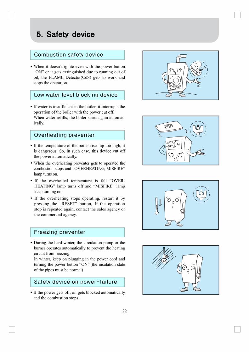
When it doesn’t ignite even with the power button “ON” or it gets extinguished due to running out of oil, the FLAME Detector(CdS) gets to work and stops the operation.
If water is insufficient in the boiler, it interrupts the operation of the boiler with the power cut off. When water refills, the boiler starts again automat-ically.
If the temperature of the boiler rises up too high, it is dangerous. So, in such case, this device cut off the power automatically.
When the overheating preventer gets to operated the combustion stops and “OVERHEATING, MISFIRE” lamp turns on.
If the overheated temperature is fall “OVER-HEATING” lamp turns off and “MISFIRE” lamp keep turning on.
If the overheating stops operating, restart it by pressing the “RESET” button, If the operation stop is repeated again, contact the sales agency or the commercial agency.
During the hard winter, the circulation pump or the burner operates automatically to prevent the heating circuit from freezing. In winter, keep on plugging in the power cord and turning the power button “ON”.(the insulation state of the pipes must be normal)
If the power gets off, oil gets blocked automatically and the combustion stops.
5. Safety device
Combustion safety device
Low water level blocking device
Overheating preventer
Freezing preventer
Safety device on power-failure

23
Check out whether the combustibles is near.
Keep cleaning all the time and don’t let the dust accumulated.
Check out whether oil leaks from, is stacked on, or soaks into the oil tank, oil pipes, the body of the boiler, etc.
Check out whether there is any water leakage from the body of the boiler and the pipes.
Open the drain plug of the oil tank regularly and remove water.
6. Everyday Checking
Points to be checked once or more a year

24
Much soot accumulated inside the boiler will reduce the life and efficiency. At least once a year, clean the boiler inside.
In case that the oil filter gets dirty, stop operating, lock the oil valve, and remove dust or rust accu-mulated below the oil cup.
Detach the oil cup by rotating right and left.
Pull down the filter.
Wash the filter and the inside of the oil cup with clean kerosene and light oil.
Water may get mired in during feeding oil or get accu-mulated naturally during the long period in the oil tank. In this case, drain water off through the drain plug in the oil tank, and when oil starts to get out, lock it.
Cleaning of boiler
Cleaning the oil filter
Cleaning the oil tank

25
If the light-receiving surface(sensing surface) gets darkened with soot, the bad sensitivity cause the wrong automatic operation.
You can pull out the flame detector(black) which is attached in the lower part of the burner.
Wipe the glassy surface of the flame detector with a scrap and fix it in its oposition.
At least once a year, check for any loose joints in the discharge(piping and flue), clogging in flue, corrosion or leak. If any abnormality is found, contact out sales agency for checking up.(blocking pipes or holes, and so on)
Cleaning the flame detector
Checking the exhaust pipe
26
There is no parts which gets wear in a short period, but when the replacement of the parts is needed, consult to out sales agency or commercial agency.
For the repair of the boiler, request to our sales agency or commercial agency, or to the A/S center.
Repairing the boiler by a man without qualification cause another trouble, so never do that.
7. How to replace the parts
27
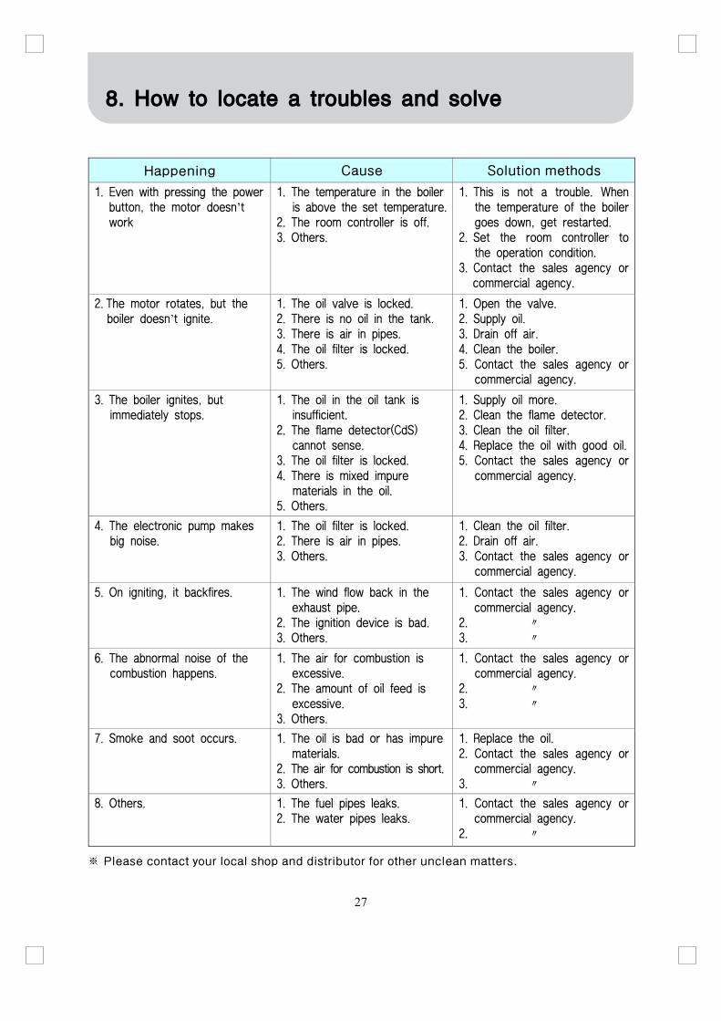
Happening Cause Solution methods
1. Even with pressing the power button, the motor doesn’t work
1. The temperature in the boileris above the set temperature.
2. The room controller is off. 3. Others.
1. This is not a trouble. When the temperature of the boiler goes down, get restarted.
2. Set the room controller to the operation condition.
3. Contact the sales agency or commercial agency.
2. The motor rotates, but the boiler doesn’t ignite.
1. The oil valve is locked. 2. There is no oil in the tank. 3. There is air in pipes. 4. The oil filter is locked. 5. Others.
1. Open the valve. 2. Supply oil. 3. Drain off air. 4. Clean the boiler. 5. Contact the sales agency or
commercial agency.
3. The boiler ignites, but immediately stops.
1. The oil in the oil tank is insufficient.
2. The flame detector(CdS) cannot sense.
3. The oil filter is locked. 4. There is mixed impure
materials in the oil. 5. Others.
1. Supply oil more. 2. Clean the flame detector. 3. Clean the oil filter. 4. Replace the oil with good oil.5. Contact the sales agency or
commercial agency.
4. The electronic pump makes big noise.
1. The oil filter is locked. 2. There is air in pipes. 3. Others.
1. Clean the oil filter. 2. Drain off air. 3. Contact the sales agency or
commercial agency.
5. On igniting, it backfires. 1. The wind flow back in the exhaust pipe.
2. The ignition device is bad. 3. Others.
1. Contact the sales agency or commercial agency.
2. ″ 3. ″
6. The abnormal noise of the combustion happens.
1. The air for combustion is excessive.
2. The amount of oil feed is excessive.
3. Others.
1. Contact the sales agency or commercial agency.
2. ″ 3. ″
7. Smoke and soot occurs. 1. The oil is bad or has impurematerials.
2. The air for combustion is short.3. Others.
1. Replace the oil. 2. Contact the sales agency or
commercial agency. 3. ″
8. Others. 1. The fuel pipes leaks. 2. The water pipes leaks.
1. Contact the sales agency or commercial agency.
2. ″
※ Please contact your local shop and distributor for other unclean matters.
8. How to locate a troubles and solve
28
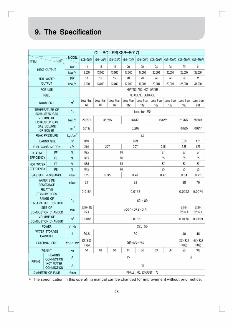
OIL BOILER(KSB-8017)
MODEL ITEM UNIT KDB-90FA KDB-130FA KDB-134FC KDB-172FA KDB-174FC KDB-200FA KDB-200FC KDB-250FA KDB-350FA
KW 11 15 15 20 20 24 24 29 41 HEAT OUTPUT
kcal/h 9,000 13,000 13,000 17,000 17,000 20,000 20,000 25,000 35,000
KW 11 15 15 20 20 24 24 29 41 HOT WATER OUTPUT kcal/h 9,000 13,000 13,000 17,000 17,000 20,000 20,000 25,000 35,000
FOR USE HEATING AND HOT WATER
FUEL KEROSENE, LIGHT-OIL
ROOM SIZE m2 Less than
60
Less than
86
Less than
86 Less than
112 Less than
112 Less than
132 Less than
132 Less than
165 Less than
231 TEMPERATURE OF EXHAUSTED GAS
℃ Less than 250
VOLUME OF EXHAUSTED GAS
Nm3/h 29.0671 32.7665 36.6421 45.6265 51.2637 68.8801
GAS VOLUME OF BOILER
mm3 0.0138 0.0205 0.0265 0.0317
PEAK PRESSURE kgf/cm2 2.5
HEATING SIZE m2 0.59 0.79 0.98 1.21
FUEL CONSUMPTION ℓ/h 2.01 2.27 2.27 3.15 3.55 4.77
FF % 89.5 88 87 87 87 HEATING EFFICIENCY FE % 88.5 86 85 85 85
FF % 88.5 88 87 87 87 HOT WATER EFFICIENCY FE % 87.5 86 85 85 85
GAS SIDE RESISTANCE mbar 0.27 0.35 0.41 0.48 0.64 0.72
WATER SIDE RESISTANCE
mbar 27 32 58 70
RELATIVE STANDBY LOSS
0.0154 0.0138 0.0092 0.0074
RANGE OF TEMPERATURE CONTROL
℃ 52 ~ 80
SIZE OF COMBUSTION CHAMBER
mm Φ240×225
×2.3t Φ270×254×2.3t
Φ310×
255×2.3t
Φ330×
255×2.3t
VOLUME OF COMBUSTION CHAMBER
m3 0.0088 0.0136 0.0176 0.0199
POWER V, Hz 220, 50
WATER STORAGE CAPACITY
ℓ 20.5 30 40 45
EXTERNAL SIZE W×L×Hmm 302×500×764
362×632×855 382×632×855
402×632×855
WEIGHT kg 51 81 84 81 84 83 86 90 103
HEATING CONNECTION
A 25 32 PIPING
HOT WATER CONNECTION
A 15
DIAMETER OF FLUE φmm INHALE : 60, EXHAUST : 75
※ The specification in this operating manual can be changed for improvement without prior notice.
9. The Specification

29
OIL BOILER
MODEL ITEM UNIT KDB-132ST KDB-172ST KDB-203ST KDB-253ST KDB-253STG KDB-353ST
KW 18 20.3 23.2 29 - 40.7 HEAT OUTPUT
kcal/h 15,500 17,500 20,000 25,000 - 35,000
KW 18 20.3 23.2 29 29 40.7 HOT WATER OUTPUT kcal/h 15,500 17,500 20,000 25,000 25,000 35,000
FOR USE HEATING AND HOT WATER HOT WATER HEATING ANDHOT WATER
FUEL KEROSENE, LIGHT-OIL
ROOM SIZE m2 Less than
102 Less than
115 Less than
132 Less than
165 - Less than 231
TEMPERATURE OF EXHAUSTED GAS
℃ Less than 250
VOLUME OF EXHAUSTED GAS
Nm2/h 29.0363 32.7318 36.6033 51.2637 65.7092
GAS VOLUME OF BOILER
mm3 0.0150 0.0155 0.0252 0.0347
PEAK PRESSURE kgf/cm2 3.5
HEATING SIZE m2 0.84 0.92 1.08 1.43
FUEL CONSUMPTION ℓ/h 2.01 2.27 2.54 3.55 4.54
FF % 90 90 90 90 - 90.7 HEATING EFFICIENCY FE % 90 90 90 90 - 90.7
FF % 90 90 90 90 90 90.7 HOT WATER EFFICIENCY FE % 90 90 90 90 90 90.7 GAS SIDE RESISTANCE mbar 0.38 0.52 0.67 0.78
WATER SIDE RESISTANCE
mbar 38 42 45 78.5
RELATIVE STANDBY LOSS
0.0180 0.0098 0.00781
RANGE OF TEMPERATURE CONTROL
℃ 52 ~ 80
SIZE OF COMBUSTION CHAMBER
mm Φ253×322.5×1.5t Φ253×
341.8×1.5tΦ283×346×1.5t
Φ320×336.5×2.0t
VOLUME OF COMBUSTION CHAMBER
m3 0.0157 0.0167 0.0213 0.0271
POWER V, Hz 220, 50
WATER STORAGE CAPACITY
ℓ 18 20 25 31.6
EXTERNAL SIZE W×L×Hmm 322×520×800 322×520×860 350×550×855 402×691×910
WEIGHT kg 42 44 48 44 68
HEATING CONNECTION
A 25 - 32 PIPING
HOT WATER CONNECTION
A 15 25 15
DIAMETER OF FLUE φmm INHALE : 60, EXHAUST : 75 INHALE : 70, EXHAUST : 75 INHALE : 60 EXHAUST : 75
※ The specification in this operating manual can be changed for improvement without prior notice.

30
■ MODEL NO : KDB-90FA, 130FA, 172FA, 200FA, 250FA, 350FA, 132ST, 172ST, 203ST, 253ST, 353ST
■ MODEL NO : KDB-90FA, 130FA, 172FA, 200FA, 250FA, 350FA, 132ST, 172ST, 203ST, 253ST, 353ST
10. Electric wiring diagram
31
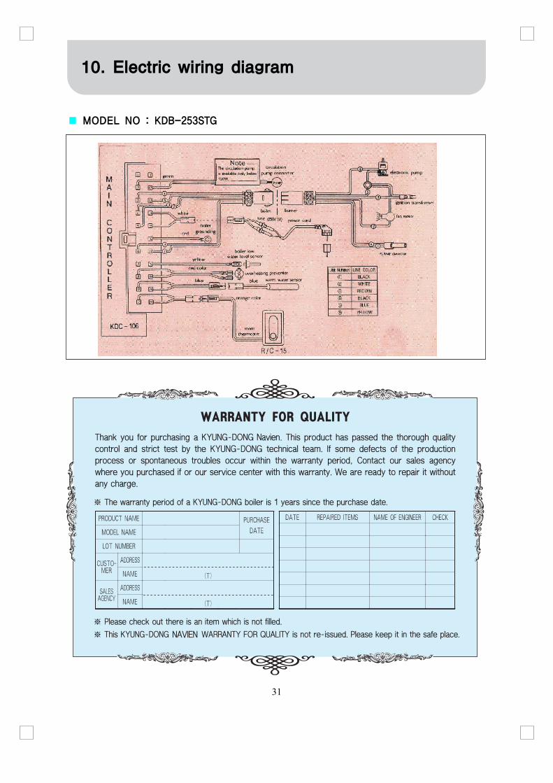
■ MODEL NO : KDB-253STG
10. Electric wiring diagram

32
MEMO

33
11. After-sales Service