katalog 2 en - hansa-flex · tolerances: din 10305-4 note: the stated pressure designation refers...
TRANSCRIPT

Edition: 02/2008 Catalogue 2
6
301
Hydraulic pipes
Hydraulic pipes

Edition: 02/2008Catalogue 2
6
302
Hydraulic pipes Note
All the information in this catalogue is based on the standards applicable at the time of publication and the regu-
lations of the employers‘ liability insurance associations. Product safety can only be guaranteed if our assembly
instructions are followed correctly. Failure to follow any of these instructions may affect the operational safety
of the product and invalidate our warranty. Our warranty in any event only covers HANSA-FLEX products. Our
products are constantly being updated, technical modifications are possible.
While we take every care in editing and checking the catalogue we cannot rule out possible errors or omissions
and accept no liability for the information it contains.
® 2008 HANSA-FLEX Hydraulik GmbH – www.hansa-flex.com
Information about fitting, installation, pressure loads and permissible operating temperatures can be found in
the technical information for pipe fittings.
Edition: 02/2008 Catalogue 2
6
303
Ø = External pipe diameter – PN = Nominal pressure PB = Max. operating pressure
L = Pipe length approx. 6 metres
Hydraulic pipes Metric precision steel pipes
Pipes
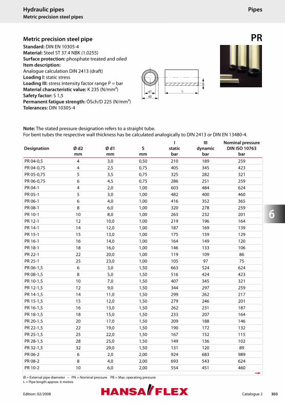
PR Metric precision steel pipe Standard: DIN EN 10305-4
Material: Steel ST 37.4 NBK (1.0255)
Surface protection: phosphate treated and oiled
Item description:
Analogue calculation DIN 2413 (draft)
Loading I: static stress
Loading III: stress intensity factor range P = bar
Material characteristic value: K 235 (N/mm2)
Safety factor: S 1,5
Permanent fatigue strength: ÓSch/D 225 (N/mm2)
Tolerances: DIN 10305-4
Note: The stated pressure designation refers to a straight tube.
For bent tubes the respective wall thickness has be calculated analogically to DIN 2413 or DIN EN 13480-4.
Designation
Ø d2
mm
Ø d1
mm
S
mm
I
static
bar
III
dynamic
bar
Nominal pressure
DIN ISO 10763
bar
PR 04-0,5 4 3,0 0,50 210 189 259
PR 04-0,75 4 2,5 0,75 405 345 423
PR 05-0,75 5 3,5 0,75 325 282 321
PR 06-0,75 6 4,5 0,75 286 251 259
PR 04-1 4 2,0 1,00 603 484 624
PR 05-1 5 3,0 1,00 482 400 460
PR 06-1 6 4,0 1,00 416 352 365
PR 08-1 8 6,0 1,00 320 278 259
PR 10-1 10 8,0 1,00 263 232 201
PR 12-1 12 10,0 1,00 219 196 164
PR 14-1 14 12,0 1,00 187 169 139
PR 15-1 15 13,0 1,00 175 159 129
PR 16-1 16 14,0 1,00 164 149 120
PR 18-1 18 16,0 1,00 146 133 106
PR 22-1 22 20,0 1,00 119 109 86
PR 25-1 25 23,0 1,00 105 97 75
PR 06-1,5 6 3,0 1,50 663 524 624
PR 08-1,5 8 5,0 1,50 516 424 423
PR 10-1,5 10 7,0 1,50 407 345 321
PR 12-1,5 12 9,0 1,50 344 297 259
PR 14-1,5 14 11,0 1,50 299 262 217
PR 15-1,5 15 12,0 1,50 279 246 201
PR 16-1,5 16 13,0 1,50 262 231 187
PR 18-1,5 18 15,0 1,50 233 207 164
PR 20-1,5 20 17,0 1,50 209 188 146
PR 22-1,5 22 19,0 1,50 190 172 132
PR 25-1,5 25 22,0 1,50 167 152 115
PR 28-1,5 28 25,0 1,50 149 136 102
PR 32-1,5 32 29,0 1,50 131 120 89
PR 06-2 6 2,0 2,00 924 683 989
PR 08-2 8 4,0 2,00 693 543 624
PR 10-2 10 6,0 2,00 554 451 460
Hydraulic pipes Metric precision steel pipes
Pipes

Edition: 02/2008Catalogue 2
6
304
Ø = External pipe diameter – PN = Nominal pressure PB = Max. operating pressure
L = Pipe length approx. 6 metres
Hydraulic pipes Metric precision steel pipes
Pipes
PR Metric precision steel pipe
Designation
Ø d2
mm
Ø d1
mm
S
mm
I
static
bar
III
dynamic
bar
Nominal pressure
DIN ISO 10763
bar
PR 12-2 12 8,0 2,00 469 391 365
PR 14-2 14 10,0 2,00 407 345 303
PR 15-2 15 11,0 2,00 380 324 279
PR 16-2 16 12,0 2,00 346 298 259
PR 18-2 18 14,0 2,00 320 278 226
PR 20-2 20 16,0 2,00 288 252 201
PR 22-2 22 18,0 2,00 262 231 181
PR 25-2 25 21,0 2,00 230 205 157
PR 28-2 28 24,0 2,00 205 184 139
PR 30-2 30 26,0 2,00 192 173 129
PR 35-2 35 31,0 2,00 152 138 109
PR 42-2 42 38,0 2,00 119 109 90
PR 06-2,25 6 1,5 2,25 1053 755 1248
PR 08-2,5 8 3,0 2,50 888 663 883
PR 10-2,5 10 5,0 2,50 711 555 624
PR 12-2,5 12 7,0 2,50 592 477 485
PR 14-2,5 14 9,0 2,50 514 423 398
PR 15-2,5 15 10,0 2,50 480 398 365
PR 16-2,5 16 11,0 2,50 450 377 337
PR 18-2,5 18 13,0 2,50 395 335 293
PR 20-2,5 20 15,0 2,50 355 305 259
PR 22-2,5 22 17,0 2,50 333 288 232
PR 25-2,5 25 20,0 2,50 293 256 201
PR 28-2,5 28 23,0 2,50 261 231 177
PR 30-2,5 30 25,0 2,50 244 217 164
PR 35-2,5 35 30,0 2,50 196 177 139
PR 38-2,5 38 33,0 2,50 181 163 127
PR 10-3 10 4,0 3,00 867 650 825
PR 12-3 12 6,0 3,00 723 562 624
PR 14-3 14 8,0 3,00 619 495 504
PR 15-3 15 9,0 3,00 578 467 460
PR 16-3 16 10,0 3,00 542 442 423
Standard: DIN EN 10305-4
Material: Steel ST 37.4 NBK (1.0255)
Surface protection: phosphate treated and oiled
Item description:
Analogue calculation DIN 2413 (draft)
Loading I: static stress
Loading III: stress intensity factor range P = bar
Material characteristic value: K 235 (N/mm2)
Safety factor: S 1,5
Permanent fatigue strength: ÓSch/D 225 (N/mm2)
Tolerances: DIN 10305-4
Note: The stated pressure designation refers to a straight tube.
For bent tubes the respective wall thickness has be calculated analogically to DIN 2413 or DIN EN 13480-4.

Edition: 02/2008 Catalogue 2
6
305
Hydraulic pipes Metric precision steel pipes
Pipes
PR Metric precision steel pipe
Designation
Ø d2
mm
Ø d1
mm
S
mm
I
static
bar
III
dynamic
bar
Nominal pressure
DIN ISO 10763
bar
PR 18-3 18 12,0 3,00 482 400 365
PR 20-3 20 14,0 3,00 433 364 321
PR 22-3 22 16,0 3,00 394 335 287
PR 25-3 25 19,0 3,00 347 299 247
PR 28-3 28 22,0 3,00 309 270 217
PR 30-3 30 24,0 3,00 289 253 201
PR 35-3 35 29,0 3,00 241 214 169
PR 38-3 38 32,0 3,00 222 198 155
PR 42-3 42 36,0 3,00 193 174 139
PR 60-3 60 54,0 3,00 130 119 365
PR 14-3,5 14 7,0 3,50 731 568 624
PR 20-3,5 20 13,0 3,50 512 421 388
PR 25-3,5 25 18,0 3,50 409 347 296
PR 12-4 12 4,0 4,00 984 717 989
PR 16-4 16 8,0 4,00 738 572 624
PR 20-4 20 12,0 4,00 590 475 460
PR 25-4 25 17,0 4,00 472 393 347
PR 28-4 28 20,0 4,00 421 355 303
PR 30-4 30 22,0 4,00 393 334 279
PR 35-4 35 27,0 4,00 331 286 234
PR 38-4 38 30,0 4,00 305 266 213
PR 42-4 42 34,0 4,00 268 236 190
PR 50-4 50 42,0 4,00 225 201 157
PR 60-4 60 52,0 4,00 182 165 95
PR 25-4,5 25 16,0 4,50 535 437 402
PR 28-4,5 28 19,0 4,50 477 396 349
PR 25-5 25 15,0 5,00 597 480 460
PR 28-5 28 18,0 5,00 533 436 398
PR 30-5 30 20,0 5,00 489 411 365
PR 35-5 35 25,0 5,00 420 355 303
PR 38-5 38 28,0 5,00 387 330 275
PR 42-5 42 32,0 5,00 343 296 245
Ø = External pipe diameter – PN = Nominal pressure PB = Max. operating pressure
L = Pipe length approx. 6 metres
Standard: DIN EN 10305-4
Material: Steel ST 37.4 NBK (1.0255)
Surface protection: phosphate treated and oiled
Item description:
Analogue calculation DIN 2413 (draft)
Loading I: static stress
Loading III: stress intensity factor range P = bar
Material characteristic value: K 235 (N/mm2)
Safety factor: S 1,5
Permanent fatigue strength: ÓSch/D 225 (N/mm2)
Tolerances: DIN 10305-4
Note: The stated pressure designation refers to a straight tube.
For bent tubes the respective wall thickness has be calculated analogically to DIN 2413 or DIN EN 13480-4.
Edition: 02/2008Catalogue 2
6
306
Ø = External pipe diameter – PN = Nominal pressure PB = Max. operating pressure
L = Pipe length approx. 6 metres
Hydraulic pipes Metric precision steel pipes
Pipes
PR Metric precision steel pipe
Designation
Ø d2
mm
Ø d1
mm
S
mm
I
static
bar
III
dynamic
bar
Nominal pressure
DIN ISO 10763
bar
PR 50-5 50 40,0 5,00 288 252 201
PR 38-6 38 26,0 6,00 469 391 342
PR 50-6 50 38,0 6,00 350 302 247
PR 38-7 38 24,0 7,00 552 449 414
PR 65-8 65 49,0 8,00 356 306 254
PR 60-10 60 40,0 10,00 496 410 129
PR 80-10 80 60,0 10,00 346 312 259
Standard: DIN EN 10305-4
Material: Steel ST 37.4 NBK (1.0255)
Surface protection: phosphate treated and oiled
Item description:
Analogue calculation DIN 2413 (draft)
Loading I: static stress
Loading III: stress intensity factor range P = bar
Material characteristic value: K 235 (N/mm2)
Safety factor: S 1,5
Permanent fatigue strength: ÓSch/D 225 (N/mm2)
Tolerances: DIN 10305-4
Note: The stated pressure designation refers to a straight tube.
For bent tubes the respective wall thickness has be calculated analogically to DIN 2413 or DIN EN 13480-4.

Edition: 02/2008 Catalogue 2
6
307
Ø = External pipe diameter – PN = Nominal pressure PB = Max. operating pressure
L = Pipe length approx. 6 metres
Hydraulic pipes Metric precision steel pipes
Pipes
PR VZ Metric precision steel pipe Standard: DIN EN 10305-4
Material: Steel ST 37.4 NBK (1.0255)
Surface protection: electro galvanised,
yellow chromized
Item description:
Analogue calculation DIN 2413 (draft)
Loading I: static stress
Loading III: stress intensity factor range P = bar
Material characteristic value: K 235 (N/mm2)
Safety factor: S 1,5
Permanent fatigue strength: ÓSch/D 225 (N/mm2)
Tolerances: DIN 10305-4
Designation
Ø d2
mm
Ø d1
mm
S
mm
I
static
bar
III
dynamic
bar
Nominal pressure
DIN ISO 10763
bar
PR 05-0,75 VZ 4 2,5 0,75 325 282 321
PR 06-0,75 VZ 6 4,5 0,75 286 251 259
PR 04-1 VZ 4 2,0 1,00 602 484 624
PR 05-1 VZ 5 3,0 1,00 482 400 460
PR 06-1 VZ 6 4,0 1,00 416 352 365
PR 08-1 VZ 8 6,0 1,00 320 278 259
PR 10-1 VZ 10 8,0 1,00 263 232 201
PR 12-1 VZ 12 10,0 1,00 219 196 164
PR 15-1 VZ 15 13,0 1,00 175 159 129
PR 18-1 VZ 18 16,0 1,00 146 133 106
PR 06-1,5 VZ 6 3,0 1,50 663 524 624
PR 08-1,5 VZ 8 5,0 1,50 516 424 423
PR 10-1,5 VZ 10 7,0 1,50 407 345 321
PR 12-1,5 VZ 12 9,0 1,50 344 297 259
PR 14-1,5 VZ 14 11,0 1,50 299 262 217
PR 15-1,5 VZ 15 12,0 1,50 279 246 201
PR 16-1,5 VZ 16 13,0 1,50 262 231 187
PR 18-1,5 VZ 18 15,0 1,50 233 207 164
PR 20-1,5 VZ 20 17,0 1,50 209 188 146
PR 22-1,5 VZ 22 19,0 1,50 190 172 132
PR 28-1,5 VZ 28 25,0 1,50 149 136 102
PR 08-2 VZ 8 4,0 2,00 693 543 624
PR 10-2 VZ 10 6,0 2,00 554 451 460
PR 12-2 VZ 12 8,0 2,00 469 391 365
PR 14-2 VZ 14 10,0 2,00 407 345 303
PR 15-2 VZ 15 11,0 2,00 380 324 279
PR 16-2 VZ 16 12,0 2,00 346 298 259
PR 18-2 VZ 18 14,0 2,00 320 278 226
PR 20-2 VZ 20 16,0 2,00 288 252 201
PR 22-2 VZ 22 18,0 2,00 262 231 181
PR 25-2 VZ 25 21,0 2,00 230 205 157
PR 28-2 VZ 28 24,0 2,00 205 184 139
Note: The stated pressure designation refers to a straight tube.
For bent tubes the respective wall thickness has be calculated analogically to DIN 2413 or DIN EN 13480-4.

Edition: 02/2008Catalogue 2
6
308
Ø = External pipe diameter – PN = Nominal pressure PB = Max. operating pressure
L = Pipe length approx. 6 metres
Hydraulic pipes Metric precision steel pipes
Pipes
PR VZ Metric precision steel pipe
Designation
Ø d2
mm
Ø d1
mm
S
mm
I
static
bar
III
dynamic
bar
Nominal pressure
DIN ISO 10763
bar
PR 35-2 VZ 35 31,0 2,00 152 138 109
PR 42-2 VZ 42 38,0 2,00 119 109 90
PR 10-2,5 VZ 10 5,0 2,50 711 555 624
PR 12-2,5 VZ 12 7,0 2,50 592 477 485
PR 14-2,5 VZ 14 9,0 2,50 514 423 398
PR 16-2,5 VZ 16 11,0 2,50 450 377 337
PR 18-2,5 VZ 18 13,0 2,50 395 335 293
PR 20-2,5 VZ 20 15,0 2,50 355 305 259
PR 22-2,5 VZ 22 17,0 2,50 333 288 232
PR 25-2,5 VZ 25 20,0 2,50 293 256 201
PR 28-2,5 VZ 28 23,0 2,50 261 231 177
PR 30-2,5 VZ 20 25,0 2,50 244 217 164
PR 38-2,5 VZ 38 23,0 2,50 181 163 127
PR 20-3 VZ 20 14,0 3,00 433 364 321
PR 25-3 VZ 25 19,0 3,00 347 299 247
PR 28-3 VZ 28 22,0 3,00 270 309 217
PR 30-3 VZ 30 24,0 3,00 289 253 201
PR 35-3 VZ 35 29,0 3,00 241 214 169
PR 38-3 VZ 38 32,0 3,00 222 198 155
PR 42-3 VZ 42 36,0 3,00 193 174 139
PR 30-4 VZ 30 22,0 4,00 393 334 279
PR 35-4 VZ 35 27,0 4,00 331 286 234
PR 38-4 VZ 38 30,0 4,00 305 266 213
PR 38-5 VZ 38 28,0 5,00 387 330 275
PR 38-6 VZ 38 26,0 6,00 469 391 342
Standard: DIN EN 10305-4
Material: Steel ST 37.4 NBK (1.0255)
Surface protection: electro galvanised,
yellow chromized
Item description:
Analogue calculation DIN 2413 (draft)
Loading I: static stress
Loading III: stress intensity factor range P = bar
Material characteristic value: K 235 (N/mm2)
Safety factor: S 1,5
Permanent fatigue strength: ÓSch/D 225 (N/mm2)
Tolerances: DIN 10305-4
Note: The stated pressure designation refers to a straight tube.
For bent tubes the respective wall thickness has be calculated analogically to DIN 2413 or DIN EN 13480-4.
Edition: 02/2008 Catalogue 2
6
309
Ø = External pipe diameter – PN = Nominal pressure PB = Max. operating pressure
L = Pipe length approx. 6 metres
Hydraulic pipes Metric precision steel pipes
Pipes
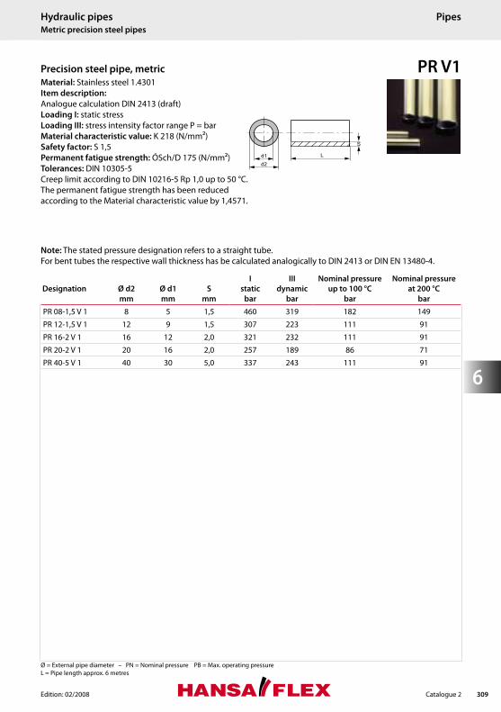
PR V1 Precision steel pipe, metric Material: Stainless steel 1.4301
Item description:
Analogue calculation DIN 2413 (draft)
Loading I: static stress
Loading III: stress intensity factor range P = bar
Material characteristic value: K 218 (N/mm2)
Safety factor: S 1,5
Permanent fatigue strength: ÓSch/D 175 (N/mm2)
Tolerances: DIN 10305-5
Creep limit according to DIN 10216-5 Rp 1,0 up to 50 °C.
The permanent fatigue strength has been reduced
according to the Material characteristic value by 1,4571.
Designation
Ø d2
mm
Ø d1
mm
S
mm
I
static
bar
III
dynamic
bar
Nominal pressure
up to 100 °C
bar
Nominal pressure
at 200 °C
bar
PR 08-1,5 V 1 8 5 1,5 460 319 182 149
PR 12-1,5 V 1 12 9 1,5 307 223 111 91
PR 16-2 V 1 16 12 2,0 321 232 111 91
PR 20-2 V 1 20 16 2,0 257 189 86 71
PR 40-5 V 1 40 30 5,0 337 243 111 91
Note: The stated pressure designation refers to a straight tube.
For bent tubes the respective wall thickness has be calculated analogically to DIN 2413 or DIN EN 13480-4.

Edition: 02/2008Catalogue 2
6
310
Ø = External pipe diameter – PN = Nominal pressure PB = Max. operating pressure
L = Pipe length approx. 6 metres
Hydraulic pipes Metric precision steel pipes
Pipes
PR V2 Metric precision steel pipe Material: Stainless steel 1.4541
Item description:
Analogue calculation DIN 2413 (draft)
Loading I: static stress
Loading III: stress intensity factor range P = bar
Material characteristic value: K 222 (N/mm2)
Safety factor: S 1,5
Permanent fatigue strength: ÓSch/D 180 (N/mm2)
Tolerances: DIN 10305-5
Creep limit according to DIN 10216-5 Rp 1,0 up to 50 °C.
The permanent fatigue strength has been reduced
according to the Material characteristic value by 1,4571.
Designation
Ø d2
mm
Ø d1
mm
S
mm
I
static
bar
III
dynamic
bar
Nominal pressure
up to 100 °C
bar
Nominal pressure
at 200 °C
bar
PR 12,7-0,91 V 2 12,7 10,88 0,91 158 121 68 61
PR 04-1 V 2 4,0 2,00 1,00 567 387 305 272
PR 06-1 V 2 6,0 4,00 1,00 379 272 178 159
PR 08-1 V 2 8,0 6,00 1,00 284 210 127 113
PR 10-1 V 2 10,0 8,00 1,00 227 171 98 88
PR 12-1 V 2 12,0 10,00 1,00 189 144 80 72
PR 14-1 V 2 14,0 12,00 1,00 162 125 68 61
PR 15-1 V 2 15,0 13,00 1,00 165 127 63 56
PR 16-1 V 2 16,0 14,00 1,00 155 119 59 52
PR 18-1 V 2 18,0 16,00 1,00 138 107 52 46
PR 20-1 V 2 20,0 18,00 1,00 124 96 46 41
PR 22-1 V 2 22,0 20,00 1,00 113 88 42 37
PR 28-1 V 2 28,0 26,00 1,00 88 69 33 29
PR 08-1,5 V 2 8,0 5,00 1,50 469 328 207 184
PR 10-1,5 V 2 10,0 7,00 1,50 375 270 157 140
PR 12-1,5 V 2 12,0 9,00 1,50 313 229 127 113
PR 15-1,5 V 2 15,0 12,00 1,50 250 187 98 88
PR 16-1,5 V 2 16,0 13,00 1,50 234 176 91 81
PR 18-1,5 V 2 18,0 15,00 1,50 220 166 80 72
PR 20-1,5 V 2 20,0 17,00 1,50 187 143 80 72
PR 22-1,5 V 2 22,0 19,00 1,50 180 137 65 58
PR 23-1,5 V 2 23,0 20,00 1,50 163 125 61 55
PR 30-1,5 V 2 30,0 27,00 1,50 132 102 46 41
PR 32-1,5 V 2 32,0 29,00 1,50 110 86 43 39
PR 35-1,5 V 2 35,0 32,00 1,50 101 79 39 35
PR 40-1,5 V 2 40,0 37,00 1,50 87 69 34 31
PR 10-2 V 2 10,0 6,00 2,00 523 360 225 200
PR 12-2 V 2 12,0 8,00 2,00 436 308 178 159
PR 14-2 V 2 14,0 10,00 2,00 374 269 148 132
PR 15-2 V 2 15,0 11,00 2,00 349 253 136 122
Note: The stated pressure designation refers to a straight tube.
For bent tubes the respective wall thickness has be calculated analogically to DIN 2413 or DIN EN 13480-4.

Edition: 02/2008 Catalogue 2
6
311
Hydraulic pipes Metric precision steel pipes
Pipes
PR V2 Metric precision steel pipe
Designation
Ø d2
mm
Ø d1
mm
S
mm
I
static
bar
III
dynamic
bar
Nominal pressure
up to 100 °C
bar
Nominal pressure
at 200 °C
bar
PR 16-2 V 2 16,0 12,00 2,00 327 239 127 113
PR 18-2 V 2 18,0 14,00 2,00 302 222 111 99
PR 20-2 V 2 20,0 16,00 2,00 261 195 98 88
PR 22-2 V 2 22,0 18,00 2,00 238 178 88 79
PR 25-2 V 2 25,0 21,00 2,00 217 164 77 68
PR 28-2 V 2 28,0 24,00 2,00 194 147 68 61
PR 30-2 V 2 30,0 26,00 2,00 181 138 63 56
PR 32-2 V 2 32,0 28,00 2,00 157 121 59 52
PR 34-2 V 2 34,0 30,00 2,00 147 114 55 49
PR 38-2 V 2 38,0 34,00 2,00 102 132 49 44
PR 42-2 V 2 42,0 38,00 2,00 112 88 44 39
PR 54-2 V 2 54,0 50,00 2,00 82 64 34 30
PR 60,3-2 V 2 60,3 56,30 2,00 78 62 30 27
PR 76,1-2 V 2 76,1 72,10 2,00 62 49 24 21
PR 25-2,5 V 2 25,0 20,00 2,50 277 205 98 88
PR 18-2,5 V 2 18,0 13,00 2,50 373 268 143 128
PR 28-2,5 V 2 28,0 23,00 2,50 247 185 87 77
PR 26,9-2,6 V 2 26,9 21,70 2,60 268 199 95 84
PR 48,3-2,6 V 2 48,3 43,10 2,60 134 104 50 45
PR 20-3 V 2 20,0 14,00 3,00 420 298 157 140
PR 25-3 V 2 25,0 19,00 3,00 336 244 121 108
PR 28-3 V 2 28,0 22,00 3,00 292 216 106 95
PR 30-3 V 2 30,0 24,00 3,00 273 202 98 88
PR 38-3 V 2 38,0 32,00 3,00 210 159 76 67
PR 26,9-3,2 V 2 26,9 20,50 3,20 326 238 12 107
PR 30-4 V 2 30,0 22,00 4,00 371 267 136 122
Ø = External pipe diameter – PN = Nominal pressure PB = Max. operating pressure
L = Pipe length approx. 6 metres
Material: Stainless steel 1.4541
Item description:
Analogue calculation DIN 2413 (draft)
Loading I: static stress
Loading III: stress intensity factor range P = bar
Material characteristic value: K 222 (N/mm2)
Safety factor: S 1,5
Permanent fatigue strength: ÓSch/D 180 (N/mm2)
Tolerances: DIN 10305-5
Creep limit according to DIN 10216-5 Rp 1,0 up to 50 °C.
The permanent fatigue strength has been reduced
according to the Material characteristic value by 1,4571.
Note: The stated pressure designation refers to a straight tube.
For bent tubes the respective wall thickness has be calculated analogically to DIN 2413 or DIN EN 13480-4.

Edition: 02/2008Catalogue 2
6
312
Ø = External pipe diameter – PN = Nominal pressure PB = Max. operating pressure
L = Pipe length approx. 6 metres
Hydraulic pipes Metric precision steel pipes
Pipes
PR V4 Metric precision steel pipe Material: Stainless steel 1.4571
Item description:
Analogue calculation DIN 2413 (draft)
Loading I: static stress
Loading III: stress intensity factor range P = bar
Material characteristic value: K 234 (N/mm2)
Safety factor: S 1,5
Permanent fatigue strength: ÓSch/D 190 (N/mm2)
Tolerances: DIN 10305-05
Creep limit according to DIN 10216-5 Rp 1,0 up to 50 °C.
Designation
Ø d2
mm
Ø d1
mm
S
mm
I
static
bar
III
dynamic
bar
Nominal pressure
up to 100 °C
bar
Nominal pressure
at 200 °C
bar
PR 04-1 V 4 4,0 2,0 1,0 600 408 321 289
PR 06-1 V 4 6,0 4,0 1,0 400 287 188 169
PR 08-1 V 4 8,0 6,0 1,0 300 222 133 120
PR 10-1 V 4 10,0 8,0 1,0 240 181 103 93
PR 12-1 V 4 12,0 10,0 1,0 200 152 84 76
PR 15-1 V 4 15,0 13,0 1,0 174 134 66 60
PR 18-1 V 4 18,0 16,0 1,0 145 112 54 49
PR 06-1,5 V 4 6,0 3,0 1,5 660 442 321 289
PR 08-1,5 V 4 8,0 5,0 1,5 495 347 217 196
PR 10-1,5 V 4 10,0 7,0 1,5 396 285 165 149
PR 12-1,5 V 4 12,0 9,0 1,5 330 242 133 120
PR 14-1,5 V 4 14,0 11,0 1,5 283 210 112 101
PR 15-1,5 V 4 158,0 12,0 1,5 264 197 103 93
PR 16-1,5 V 4 16,0 13,0 1,5 261 195 96 87
PR 18-1,5 V 4 18,0 15,0 1,5 232 175 84 76
PR 22-1,5 V 4 22,0 19,0 1,5 190 145 68 61
PR 25-1,5 V 4 25,0 22,0 1,5 167 128 59 53
PR 28-1,5 V 4 28,0 25,0 1,5 149 115 52 47
PR 33,7-1,6 V 4 33,7 30,5 1,6 126 98 46 42
PR 48,3-1,6 V 4 48,3 45,1 1,6 77 32 32 29
PR 08-2 V 4 8,0 4,0 2,0 690 458 321 289
PR 10-2 V 4 10,0 6,0 2,0 552 380 236 213
PR 12-2 V 4 12,0 8,0 2,0 460 325 188 169
PR 14-2 V 4 14,0 10,0 2,0 394 284 156 140
PR 15-2 V 4 15,0 11,0 2,0 368 267 143 129
PR 16-2 V 4 16,0 12,0 2,0 345 252 133 120
PR 18-2 V 4 18,0 14,0 2,0 318 234 116 105
PR 20-2 V 4 20,0 16,0 2,0 287 213 103 93
PR 21,3-2 V 4 21,3 17,3 2,0 269 201 96 87
PR 22-2 V 4 22,0 18,0 2,0 260 195 93 84
PR 25-2 V 4 25,0 21,0 2,0 229 173 81 73
PR 28-2 V 4 28,0 24,0 2,0 205 156 71 64
Note: The stated pressure designation refers to a straight tube.
For bent tubes the respective wall thickness has be calculated analogically to DIN 2413 or DIN EN 13480-4.

Edition: 02/2008 Catalogue 2
6
313
Hydraulic pipes Metric precision steel pipes
Pipes
PR V4 Metric precision steel pipe
Designation
Ø d2
mm
Ø d1
mm
S
mm
I
static
bar
III
dynamic
bar
Nominal pressure
up to 100 °C
bar
Nominal pressure
at 200 °C
bar
PR 30-2 V 4 30,0 26,0 2,0 191 146 66 60
PR 35-2 V 4 36,0 32,0 2,0 151 117 56 51
PR 42-2 V 4 42,0 38,4 2,0 118 92 46 42
PR 42,4-2 V 4 42,4 38,4 2,0 117 92 46 41
PR 17,2-2,3 V 4 17,2 12,6 2,3 375 272 144 130
PR 14-2,5 V 4 14,0 9,0 2,5 505 353 204 184
PR 16-2,5 V 4 16,0 11,0 2,5 442 314 173 156
PR 18-2,5 V 4 18,0 13,0 2,5 393 283 151 136
PR 20-2,5 V 4 20,0 15,0 2,5 345 258 133 120
PR 22-2,5 V 4 22,0 17,0 2,5 321 236 119 108
PR 25-2,5 V 4 25,0 20,0 2,5 292 216 103 93
PR 28-2,5 V 4 28,0 23,0 2,5 260 195 91 82
PR 30-2,5 V 4 30,0 25,0 2,5 243 183 84 76
PR 35-2,5 V 4 35,0 30,0 2,5 196 149 71 64
PR 42,4-2,6 V 4 42,4 37,2 2,6 161 124 61 55
PR 60,3-2,9 V 4 60,3 54,5 2,9 121 95 47 42
PR 76,1-2,9 V 4 76,1 70,3 2,9 90 71 37 33
PR 88,9-2,9 V 4 88,9 83,1 2,9 71 57 31 28
PR 12-3 V 4 12,0 6,0 3,0 694 461 321 289
PR 16-3 V 4 16,0 10,0 3,0 540 373 217 196
PR 20-3 V 4 20,0 14,0 3,0 432 308 165 149
PR 22-3 V 4 22,0 16,0 3,0 392 283 147 133
PR 25-3 V 4 25,0 19,0 3,0 345 252 127 115
PR 30-3 V 4 30, 26,0 3,0 288 214 103 93
PR 42-3 V 4 42,0 36,0 3,0 193 147 71 64
PR 33,7-3,2 V 4 33,7 27,3 3,2 274 205 97 88
PR 48,3-3,2 V 4 48,3 41,9 3,2 180 138 66 59
PR 42,4-3,2 V 4 42,4 36 3,2 206 156 76 68
PR 88,9-3,2 V 4 88,9 82,5 3,2 82 65 35 31
PR 114,3-3,2 V 4 114,3 107,9 3,2 54 43 27 24
PR 30-4 V 4 30,0 22,0 4,0 392 282 143 129
PR 38-4 V 4 38,0 30,0 4,0 303 224 109 99
PR 38-5 V 4 38,0 28,0 5,0 385 278 141 127 Ø = External pipe diameter – PN = Nominal pressure PB = Max. operating pressure
L = Pipe length approx. 6 metres
Material: Stainless steel 1.4571
Item description:
Analogue calculation DIN 2413 (draft)
Loading I: static stress
Loading III: stress intensity factor range P = bar
Material characteristic value: K 234 (N/mm2)
Safety factor: S 1,5
Permanent fatigue strength: ÓSch/D 190 (N/mm2)
Tolerances: DIN 10305-05
Creep limit according to DIN 10216-5 Rp 1,0 up to 50 °C.
Note: The stated pressure designation refers to a straight tube.
For bent tubes the respective wall thickness has be calculated analogically to DIN 2413 or DIN EN 13480-4.

Edition: 02/2008Catalogue 2
6
314
Ø = External pipe diameter – PN = Nominal pressure PB = Max. operating pressure
L = Pipe length approx. 6 metres
Hydraulic pipes French precision steel pipes
Pipes
PR franzoesisch French precision steel pipe Material: Steel ST 37.4 NBK (1.0255)
Surface protection: electro galvanised,
yellow chromized
Item description: Calculation as in DIN ISO 10763 (DIN handbook 174 – Page 416)
Temperature range: -20 °C to +120 °C
Load: Kinetic (dynamic load)
Safety: 4 : 1
Designation
Ø d2
mm
Ø d1
mm
S
mm
Nominal pressure
bar
PR 13 13,25 8,75 2,25 374
PR 17 16,75 11,25 2,75 358
PR 21 21,25 14,75 3,25 329
PR 27 26,75 20,25 3,25 251
PR 33 33,5 25,4 4,05 249

Edition: 02/2008 Catalogue 2
6
315
Ø = External pipe diameter – PN = Nominal pressure PB = Max. operating pressure
Hydraulic pipes Angle 90°
Pipe bends
RB Pipe bend 90 Standard: DIN 2391/C
Material: Steel ST 37.4 NBK (1.0255)
Surface protection: phosphate treated and
oiled
Item description: Seamless pipe bend 90° for minimum loss of fl ow
Designation
Ø
mm
S
mm
Internal Ø
mm
Bending radius R
mm
a
mm
b
mm
L1
mm
L2
mm
RB 14-1,5 14 1,5 11 30 200 40 230 70
RB 15-1,5 15 1,5 12 30 200 40 230 70
RB 15-2 15 2,0 11 30 200 40 230 70
RB 16-2 16 2,0 12 30 200 40 230 70
RB 18-1,5 18 1,5 15 36 200 35 236 71
RB 18-2 18 2,0 14 36 200 35 236 72
RB 20-2 20 2,0 16 36 200 45 236 81
RB 20-2,5 20 2,5 15 36 200 45 236 81
RB 20-3 20 3,0 14 36 200 45 236 81
RB 22-1,5 22 1,5 19 38 200 40 238 78
RB 22-2 22 2,0 18 38 200 40 238 78
RB 22-2,5 22 2,5 17 38 200 40 238 78
RB 22-3,5 22 3,5 15 38 200 40 238 78
RB 25-2 25 2,0 21 44 200 50 244 94
RB 25-2,5 25 2,5 20 44 200 50 244 94
RB 25-3 25 3,0 19 44 200 50 244 94
RB 25-4 25 4,0 17 44 200 50 244 94
RB 28-1,5 28 1,5 25 48 200 50 248 98
RB 28-2 28 2,0 24 48 200 50 248 98
RB 28-3 28 3,0 22 48 200 50 248 98
RB 30-2,5 30 2,5 25 50 200 60 250 110
RB 30-3 30 3,0 24 50 200 60 250 110
RB 30-4 30 4,0 22 50 200 60 250 110
RB 35-2 35 2,0 31 60 200 65 260 125
RB 35-3 35 3,0 29 60 200 65 260 125
RB 38-2,5 38 2,5 33 65 200 75 265 140
RB 38-3 38 3,0 32 65 200 75 265 140
RB 38-4 38 4,0 30 65 200 75 265 140
RB 38-5 38 5,0 28 65 200 75 265 140

Edition: 02/2008Catalogue 2
6
316
Hydraulic pipes Angle 90°
Pipe bends
RB Pipe bend 90 Standard: DIN 2391/C
Material: Steel ST 37.4 NBK (1.0255)
Surface protection: phosphate treated and
oiled
Item description: Seamless pipe bend 90° for minimum loss of fl ow
Designation
Ø
mm
S
mm
Internal Ø
mm
Bending radius R
mm
a
mm
b
mm
L1
mm
L2
mm
RB 42-2 42 2,0 38 80 200 85 280 165
RB 42-3 42 3,0 36 80 200 85 280 165
RB 50-6 50 6,0 38 210 100 100 310 310
RB 65-8 65 8,0 49 210 110 110 320 320
RB 80-10 80 10,0 60 210 120 120 330 330
Ø = External pipe diameter – PN = Nominal pressure PB = Max. operating pressure