kansas water technologies
TRANSCRIPT

Completed for:
Kansas Water Technologies
SN#130241575
1st Element, 1st Pass
March 2014 WO#120313-2
MEMBRANE AUTOPSY REPORT

Avista Technologies, Inc. Page 1 of 27
EXECUTIVE SUMMARY 2
INITIAL ELEMENT TEST RESULTS 4
Element Weight 4
Wet Test 4
Integrity Test 5
EXTERNAL INSPECTION 6
Spiral-Wound Membrane Element Construction 6
Fiberglass Casing 8
Brine Seal 8
Permeate Tube 8
Anti-Telescoping Device (ATD) 9
INTERNAL INSPECTION & TESTING 10
Scroll End Examination 10
Membrane Surface Visual Examination 11
Feed Spacer Visual Examination 12
Permeate Spacer Visual Examination 12
Glue Line Integrity Examination 12
Testing for the Presence of Oxidizing Halogens 13
CELL TEST FOR PERMEATE FLOW & SALT PASSAGE 14
FOULANT ANALYSIS 15
Organic Content Testing 15
Foulant Density Measurement 15
Testing for Presence of Carbonates 15
Testing for the Presence of Microbiological Organisms 15
Testing for the Presence of Coagulant 16
Fourier Transform Infrared Spectroscopy Analysis 17
Testing to Identify Inorganic Foulant Constituents 20
Chromatic Elemental Imaging (CEI) 22
Testing Comments and Interpretation 23
CELL TEST & LABORATORY CLEAN-IN-PLACE STUDY 24
Additional Testing 25
Gas Chromatography-Mass Spectrometry (GC-MS) 25
High Pressure Liquid Chromatography 26
CERTIFICATION BY LABORATORY 27
TABLE OF CONTENTS

Avista Technologies, Inc. Page 2 of 27
EXECUTIVE SUMMARY
Background Kansas Water Technologies provided one reverse osmosis element to Avista Technologies for dissection and analysis. Field data from the Sunflower Electric RO system showed a steady decline in flow from start up. Furthermore, cleaning was unable to completely recover flow back to baseline. Element SN#130241575 was removed from the first position of the first pass.
Initial Element Testing Element SN# 130241575 produced lower than normal flow (76% of normal), lower than normal rejection (98.2%) and normal delta pressure (5 psi) upon baseline wet testing.
External Inspection The fiberglass casing, anti-telescoping devices (ATDs), brine seal and permeate tube were in good mechanical condition. The element passed integrity testing, indicating that there was no damage to the internal mechanical components of the spiral-wound element.
Internal Inspection and Testing Black colored particles were observed on the feed scroll end (brine seal end) of the element. The concentrate scroll end was virtually free of visible foulant material. Extruding feed spacer was observed on both scroll ends during examination. The exposed membrane surfaces were virtually free of visible foulant material, except on the glue line of the feed end of the element where black particles were present. The glue lines and permeate spacers were in good mechanical condition. The element also tested negative for the presence of halogens (e.g. chlorine) in the membrane structure.
Cell Testing Results Flat sheet samples harvested from the full element produced 76% of normal water passage and 128% of normal salt passage.

Avista Technologies, Inc. Page 3 of 27
Foulant Analysis Due to the lack of removable foulant material on the membrane surface the organic content (loss on ignition), foulant density and zeta potential could not be determined. Moreover, a sample could not be scraped from the surface to perform microscope analysis. The Energy Dispersive X-ray (EDX) analysis primarily identified components representative of the membrane material itself (carbon, oxygen and sulfur) and organics. The high sulfur weight percentage (6.86%), contributed by the membrane material, also confirmed the lack of foulant. The only inorganics detected were trace amounts (<0.20%) of silicon and aluminum. The Scanning Electron Microscope (SEM) images showed predominantly the membrane material itself with randomly dispersed particles and isolated regions of granular and smooth foulant. Chromatic Elemental Imaging (CEI) confirmed the relative lack of foulant material by displaying primarily the elements which represent the membrane material itself (alternating carbon and sulfur). The granular material was identified as a combination of clay (aluminum silicate), colloidal silica and aluminum hydroxide. The smooth deposits showed a higher concentration of carbon, confirming organics were present.
Cleaning Study Results Flat sheet samples harvested from the full element were cleaned with various cleaner combinations. Cleaning results showed losses in water passsage in the flat sheet samples from SN#130241575 which were not observed when used on new Toray TM720D-400. This indicates that the losses in water passage were due to the foulant material on the membrane surface of SN#130241575.
Additional Comments High Pressure Liquid Chromatography (HPLC) and Gas Chromatography-Mass Spectroscopy (GC-MS)
were also performed on fouled and new flat sheet samples from a Toray TM720D. Both the HPLC and
GC-MS analysis identified identical peaks on the fouled and new flat sheet samples (i.e. no obvious
contaminants were identified). Fourier Transform Infrared (FT-IR) spectroscopy of the fouled membrane
surface was compared to a new Toray TM720D membrane. The fouled membrane FT-IR identified a
broad band between 1100 and 900 cm-1 which was not present on the new membrane FT-IR spectrum.
FT-IR analysis was also conducted on the oil used onsite (on the well head) and a feed water sample
provided. The same broad peak was identified in the feed water sample but not the oil sample. The
bands identified in the feed water spectrum were then compared to the spectra in the FT-IR library (see
top 5 library matches on page 17). The components identified may be associated with agricultural
products (i.e. pesticides). In particular, Poly (Ethylene oxide) can be used to form non-ionic surfactants
and Pentachlorophenol can be found in pesticides.

Avista Technologies, Inc. Page 4 of 27
INITIAL ELEMENT TEST RESULTS Element Weight Because element weight is often indicative of the degree of fouling, elements are weighed prior to the autopsy.
SN# 130241575 weighed 33 pounds; new eight inch elements weigh approximately 30 to 35 pounds.
Wet Test The element was wet tested on dechlorinated San Marcos, CA city water. Wet test results were normalized to the manufacturer’s published test conditions.
Toray TM720D-400
Flow (gpm)
Rejection (%)
Pressure Drop (psi)
SN# 130241575 4.35 98.2 5
Manufacturer’s Specifications 6.10 to 7.60 99.6 to 99.8 ≤20
Element Wet Testing

Avista Technologies, Inc. Page 5 of 27
Integrity Test To determine if a membrane performance problem is possibly caused by mechanical damage, membranes are tested to check for vacuum decay that may indicate abnormal bypass. In this test a vacuum of about 22 inches Mercury (in. Hg) is applied to the permeate side of the membrane for a duration of 120 seconds. If over 35% of the vacuum is lost within a 120 second period, then the membrane can be said to have severe physical damage. SN# 130241575 passed integrity testing.
0
10
20
30
40
50
60
70
80
90
100
0
5
10
15
20
25
30
0 15 30 45 60 75 90 105 120
Pe
rce
nt
Loss
Vac
uu
m (
in H
g)
Time (seconds)
Integrity Test Results for SN #130241575
Vacuum
Percent loss

Avista Technologies, Inc. Page 6 of 27
EXTERNAL INSPECTION The external inspection of a membrane element is an important step in the autopsy process. Physical damage to the fiberglass components can contribute to performance issues in the element or may yield clues as to the operating conditions of the membrane system that led to poor membrane performance. As most of the external components are damaged during the autopsy process, documenting any significant finds before further work is completed is essential.
This section covers the Fiberglass casing, anti-telescoping devices (ATDs), permeate tube, and brine seal. In addition the scroll ends are also examined for any foulant/scale material that may be interfering with flow and for feed spacer extrusion also known as telescoping and gapping in the scroll end which may cause localized scaling (uneven hydraulics).
Spiral-Wound Membrane Element Construction

Avista Technologies, Inc. Page 7 of 27

Avista Technologies, Inc. Page 8 of 27
Fiberglass Casing The fiberglass casing is an integral part of each element. The purpose of this wrap is to protect the element from external differential pressure, provide compressive strength to prevent telescoping and to ensure that the various membrane components are held in their correct position for optimum performance. Damage to the wrap can be an indication of rough handling or damage from excessive differential pressure across the membrane surface.
The fiberglass casing of the element was in good mechanical condition and showed no signs of physical damage.
Fiberglass casing for SN# 130241575
Brine Seal The purpose of the brine seal is to seal against the inside diameter of the pressure vessels and the outside diameter of the membrane to ensure that all the feed water passes through the membrane element. Chevron type seals are used to aid in membrane loading and to seal to a variety of pressure vessel inside surfaces.
The brine seal was in good condition and no damage was noted during the external inspection.
Permeate Tube At the center of each membrane element is a round section of pipe that is called the permeate tube. Down the length of the tube, holes are drilled through the pipe wall to the tube center. This tube is bonded to the membrane leaves and permits water to flow from the leaves outward at each end of the full element and the through the holes for collection. To function properly, the permeate tube must be free from gouges or damage that can prevent proper o-ring sealing at each end. Poor sealing can result in bypass from the high-pressure feed/concentrate flow into the permeate stream.
The permeate tube was free from damage which could allow for the bypass of feed water into the permeate stream.

Avista Technologies, Inc. Page 9 of 27
Anti-Telescoping Device (ATD) When assembled at the factory, membrane elements are commonly fitted with Anti-Telescoping Devices (ATDs) at each end of the element. These devices are designed to prevent telescoping of the membrane leaves under normal operating conditions that can cause membrane damage.
Both the feed and concentrate end anti-telescoping devices (ATDs) were in good condition.
Image of feed ATD (left) and concentrate ATD (right) for SN# 1323232845

Avista Technologies, Inc. Page 10 of 27
INTERNAL INSPECTION & TESTING Scroll End Examination Once the anti-telescoping devices are removed, the scroll ends of the membrane leaves are examined for presence of colloidal particles, biofouling, feed spacer extrusion and membrane gapping. In addition, each scroll end is examined for the gradual axial shift of the element leaves from outer diameter of the element towards the permeate tube. This type of damage is termed "telescoping" and is caused by the development of high differential pressure (usually greater than 10 psi) across the element.
Black particles were observed on the feed scroll end of the element. The concentrate scroll end was virtually free of visible foulant material. Extruding feed spacer was noted on both scroll ends.
Feed (left) and concentrate (right) scroll ends of SN# 130241575
Extruding feed spacer observed on feed (left) and concentrate (right) scroll ends

Avista Technologies, Inc. Page 11 of 27
Membrane Surface Visual Examination When assembled, the surface of the membrane is a uniform, shiny surface with no visual contamination or impurities. Although the membrane surface contamination can be sometimes hard to detect visually many times contamination is very visible and easy to detect with the naked eye. Black particles were observed on the glue line of the feed end of the element. The remainder of the exposed membrane surfaces was virtually free of visible foulant material.
Exposed membrane surface for SN#130241575
Close up image of black particles on the glue line of the feed end of the element

Avista Technologies, Inc. Page 12 of 27
Feed Spacer Visual Examination The feed spacer is a plastic net material designed to separate membrane surfaces to form a flow path and to promote turbulence within feed water channel.
The feed spacers were free of foulant debris.
Image of feed spacer of SN#130241575
Permeate Spacer Visual Examination Permeate spacer provides a path for permeate flow to channel towards the central permeate tube which minimizes permeate-side pressure losses.
The permeate spacers were in good mechanical condition.
Glue Line Integrity Examination Membrane leaves are glued on three sides to separate feed and permeate streams. Glue lines are inspected to ensure that there are no sections of unbounded material referred to as glue flaps that may block the feed channel into the element module. In some worst case situations, glue lines may fail at the feed end of the membrane permitting contamination. The glue lines are also inspected for pouching and delamination which often occur on the concentrate end of last stage elements. This type of physical damage may indicate permeate backpressure caused by positive pressure on the permeate side of the membrane.
Glue lines in the element were in good condition and showed no signs of pouching, delamination, or glue flaps.

Avista Technologies, Inc. Page 13 of 27
Testing for the Presence of Oxidizing Halogens The Fujiwara test is used to confirm that a polyamide (PA) thin-film membrane has been exposed to an oxidizing halogen, such as chlorine, bromine, or iodine. This test analyzes whether halogens have become part of the polymer structure through oxidative attack. Please note that the Fujiwara test is a qualitative test and that any color change indicates the presence of a halogen in the membrane structure. However the test does not quantify the amount of exposure or which exact halogen is attached.
Fujiwara testing for SN#130241575 was negative for the presence of halogens (e.g. chlorine) in the membrane structure.
Example of negative (left) and positive (right) Fujiwara color change
Avista Technologies, Inc. Page 14 of 27
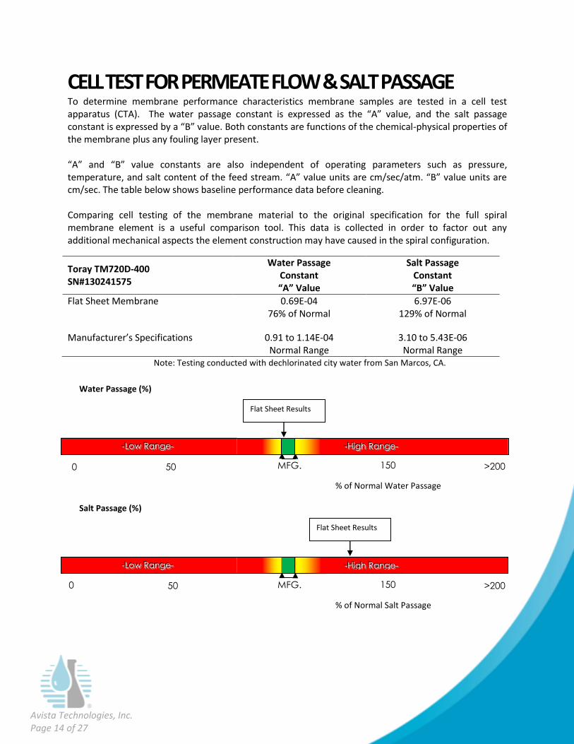
CELL TEST FOR PERMEATE FLOW & SALT PASSAGE To determine membrane performance characteristics membrane samples are tested in a cell test apparatus (CTA). The water passage constant is expressed as the “A” value, and the salt passage constant is expressed by a “B” value. Both constants are functions of the chemical-physical properties of the membrane plus any fouling layer present. “A” and “B” value constants are also independent of operating parameters such as pressure, temperature, and salt content of the feed stream. “A” value units are cm/sec/atm. “B” value units are cm/sec. The table below shows baseline performance data before cleaning. Comparing cell testing of the membrane material to the original specification for the full spiral membrane element is a useful comparison tool. This data is collected in order to factor out any additional mechanical aspects the element construction may have caused in the spiral configuration.
Toray TM720D-400 SN#130241575
Water Passage Constant “A” Value
Salt Passage Constant “B” Value
Flat Sheet Membrane 0.69E-04 76% of Normal
6.97E-06 129% of Normal
Manufacturer’s Specifications 0.91 to 1.14E-04 Normal Range
3.10 to 5.43E-06 Normal Range
Note: Testing conducted with dechlorinated city water from San Marcos, CA.
0 50 150
0
>200
0
---HHHiiiggghhh RRRaaannngggeee---
---LLLooowww RRRaaannngggeee---
MFG.
Spec
.
Salt Passage (%)
% of Normal Salt Passage
150
0
>200
0
---HHHiiiggghhh RRRaaannngggeee---
---LLLooowww RRRaaannngggeee---
MFG.
Spec
.
Water Passage (%)
% of Normal Water Passage
50 0
Flat Sheet Results
Flat Sheet Results

Avista Technologies, Inc. Page 15 of 27
FOULANT ANALYSIS Organic Content Testing Loss on ignition (LOI) testing gives an approximation of the organic content of the foulant. Values in excess of 35% typically represent the presence of organic content.
Organic content could not be determined as the membrane surfaces lacked scrapable foulant material.
Foulant Density Measurement Membrane foulant density is the weight of dry foulant per area of membrane surface. Foulant densities determined from past autopsies range from 0.02 to 1.84 mg/cm2 and average 0.49 mg/cm2.
The foulant density could not be measured due to the lack of removable foulant material.
Testing for Presence of Carbonates Acid testing is used to determine the presence of carbonates on the membrane surface. In this test, several drops of dilute hydrochloric acid were placed on the foulant surfaces. Effervescing indicates a positive test result.
No bubbling was observed when acid was applied to the active membrane surfaces indicating any carbonates present were below the visual detection limit.
Testing for the Presence of Microbiological Organisms Foulant samples were stained and examined with a light microscope at 1000x using an oil immersion lens. Gram positive bacteria are stained blue while Gram negative bacteria are stained red.
Microscope analysis could not be performed due to the lack of foulant material on the membrane surfaces.

Avista Technologies, Inc. Page 16 of 27
Testing for the Presence of Coagulant Zeta potential testing of the membrane surface foulant can determine the presence of excess coagulant by measuring the charge associated with the surface colloids. Most naturally occurring colloids are negatively charged and surrounded by a double layer of counter ions. Zeta potential is the charge that resides at the double layer boundary, which we can conveniently measure with a zeta potential meter.
Electrostatic repulsion becomes significant when two colloids approach each other and their charged double layers begin to interfere. Because of this mutual repulsion, coagulation and flocculation are difficult to accomplish and coagulants are often overfed into the RO system resulting in a positive zeta potential. Samples that show a near zero or neutral zeta potential represent the optimum coagulant dosage.
The zeta potential could not be measured as foulant material could not be collected from the membrane surface.
Image based on diagram from Particle Characterization Laboratories, Inc.

Avista Technologies, Inc. Page 17 of 27
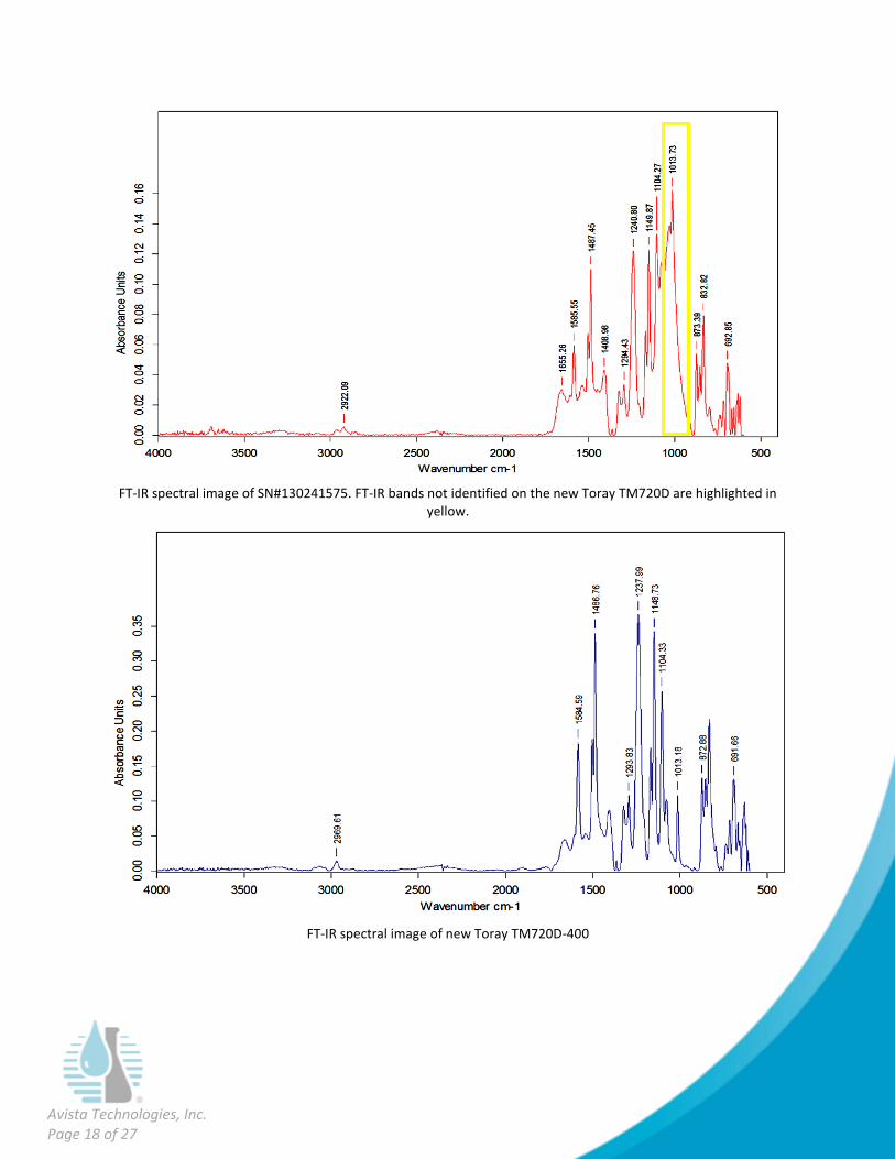
Fourier Transform Infrared Spectroscopy Analysis Fourier Transform Infrared Spectroscopy (FT-IR) analysis identifies the functional groups of organic and inorganic foulant constituents. FT-IR is a measurement technique whereby spectra are collected based on measurements of the temporal coherence of a radiative source, using time-domain measurements of the electromagnetic radiation or other type of radiation.
FT-IR spectrum of the fouled membrane surface and new Toray TM720D membrane identified a broad band between 1100 and 900 cm-1 which was not present on the new Toray membrane. FT-IR analysis was also conducted on the oil used on the well head and incoming feed water sample. The same broad peak was identified in the water sample but not the oil sample. The peaks in the feed water sample were then compared to the FT-IR library. Below are a list of the top 5 compound matches.
FT-IR Library Matches for the Feed Water Sample Provided
Compound Name Library Match (%)
1-Methoxy-2-Propanol 58
Diethylene Glycol Dimethyl Ether 56
Poly (Ethylene oxide) 55
Pentachlorophenol 54
Diethylene Glycol Monomethyl Ether 52
Avista Technologies, Inc. Page 18 of 27
FT-IR spectral image of SN#130241575. FT-IR bands not identified on the new Toray TM720D are highlighted in yellow.
FT-IR spectral image of new Toray TM720D-400

Avista Technologies, Inc. Page 19 of 27
FT-IR spectrum of DuoPrime Well Oil
FT-IR spectrum of feed water sample

Avista Technologies, Inc. Page 20 of 27
Testing to Identify Inorganic Foulant Constituents Energy Dispersive X-ray (EDX) analysis is conducted in conjunction with scanning electron microscopy (SEM) to identify inorganic foulant constituents. The electron beam in the microscope causes specimens to emit x-rays including those from the k, l and m atomic shells. Spectrometer counts of these x-rays, which are said to be “characteristic” of the elements present in the specimen, can be used to calculate composition for a full qualitative analysis. Inorganic Foulant Constituents Test Results
Elements (wt %) SN#130241575
Carbon 79.16
Oxygen 13.76
Sulfur 6.86
Silicon 0.15
Aluminum 0.07

Avista Technologies, Inc. Page 21 of 27
SEM image (150x) of the membrane surface of SN#130241575
Close up SEM image (15000x) of the membrane surface of SN#130241575

Avista Technologies, Inc. Page 22 of 27
Chromatic Elemental Imaging (CEI) Chromatic Elemental Imaging (CEI) is an analytical technique used to resolve the spatial distribution of elements in a foulant sample. In this technique, a beam of focused electrons is accelerated across the surface of a foulant sample and interacts with the sample’s inorganic elements by causing the elements to emit electrons. Since each element has its own unique atomic shell, a particular element's electron emission from its atomic shell generates a characteristic X-ray spectrum that allows for its identification. CEI assigns each element a color and provides a high resolution image of their exact location in a sample. An element’s color intensity in a Chromatic Elemental Image is largely influenced by its concentration in the foulant sample; elements present in a higher percentage will be displayed with greater intensity in the image. CEI can uniquely identify the distinct elements in a mixed foulant sample containing a number of inorganic deposits. This technique also reveals the location and concentration of different elements relative to each other in a sample.
CEI image(5000x) of the membrane surface

Avista Technologies, Inc. Page 23 of 27
Testing Comments and Interpretation The Energy Dispersive X-ray (EDX) analysis identified primarily the components representative of the membrane material itself (carbon, oxygen and sulfur) and organics. The high sulfur weight percentage (6.86%), contributed by the membrane material, also confirmed the lack of foulant. The only inorganics detected were trace amounts (<0.20%) of silicon and aluminum.
The Scanning Electron Microscope (SEM) images showed predominantly the membrane material itself with randomly dispersed particles and isolated regions of granular and smooth foulant.
Chromatic Elemental Imaging (CEI) confirmed the relative lack of foulant material by displaying primarily the elements which represent the membrane material itself (alternating carbon and sulfur). The granular material was identified as a combination of clay (aluminum silicate), colloidal silica and aluminum hydroxide. The smooth deposits showed a higher concentration of carbon, confirming organics were present.

Avista Technologies, Inc. Page 24 of 27
CELL TEST & LABORATORY CLEAN-IN-PLACE STUDY Flat sheet membrane samples harvested from the full element are placed in a cell test apparatus and cleaned with various Avista chemicals to determine the most effective cleaner combinations and the amount of time required for an effective cleaning.
Flat sheet samples harvested from the full element were cleaned with various cleaner combinations. Cleaning results showed losses in water passage in the flat sheet samples from SN#130241575 which were not observed when used on new Toray TM720D-400. This suggests that the losses in water passage were due to the foulant material on the membrane surface of SN#130241575.
Avista Technologies, Inc. Page 25 of 27
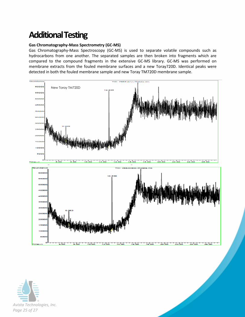
Additional Testing Gas Chromatography-Mass Spectrometry (GC-MS) Gas Chromatography-Mass Spectroscopy (GC-MS) is used to separate volatile compounds such as hydrocarbons from one another. The separated samples are then broken into fragments which are compared to the compound fragments in the extensive GC-MS library. GC-MS was performed on membrane extracts from the fouled membrane surfaces and a new Toray720D. Identical peaks were detected in both the fouled membrane sample and new Toray TM720D membrane sample.
New Toray TM720D

Avista Technologies, Inc. Page 26 of 27
High Pressure Liquid Chromatography High Pressure Liquid Chromatography (HPLC) was performed on extracts of the fouled membrane surface and a new Toray TMD720. The extracts were injected into a reverse phase column and compounds visible in the UV range were detected. Avista has correlated the 11 to 16 min (based on the gradient) with hydrophobic organic material. Comparison of the HPLC graphs from the fouled membrane to the new membrane identified identical peaks.
New Toray TM720D
Kansas Water
Avista Technologies, Inc. Page 27 of 27
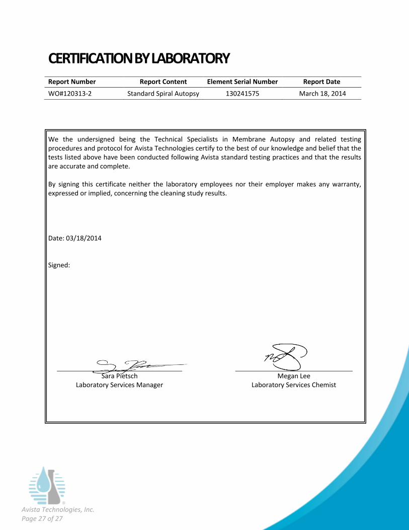
CERTIFICATION BY LABORATORY
Report Number Report Content Element Serial Number Report Date
WO#120313-2 Standard Spiral Autopsy 130241575 March 18, 2014
We the undersigned being the Technical Specialists in Membrane Autopsy and related testing procedures and protocol for Avista Technologies certify to the best of our knowledge and belief that the tests listed above have been conducted following Avista standard testing practices and that the results are accurate and complete. By signing this certificate neither the laboratory employees nor their employer makes any warranty, expressed or implied, concerning the cleaning study results. Date: 03/18/2014 Signed:
Sara Pietsch Laboratory Services Manager
Megan Lee Laboratory Services Chemist