k&t #14 inspection overview, observed defects & corrective
TRANSCRIPT

K&T #14
Inspection Overview,
Observed Defects
& Corrective Actions Jason Sobczynski
Next Generation Rail Services
Overview
During the weekend of 11/17/17 to 11/19/17 I had the opportunity to perform a
rather thorough inspection on the locomotive known as K&T 14. The first
objective was to determine to what extent the previously contracted scope of work
has or has not been completed. I am providing two percentages, the percentage of
completion as it appears, and the percentage of the work which is salvageable.
The following is a breakdown of that list and what is observed of the locomotive as
it sits:
Appears Complete, Salvagable (Percentages)
• Engineering/Project management
85%, 3% There is no documentation related to the repairs made to the boiler on
site/ given the volume of rework required for the boiler to be made serviceable
(among other issues) I consider there to have been no project management
provided by the contractor.
• Boiler, Steam, & Combustion Systems
90%, 0% While work has been performed and there is the perception of
completion, the work was performed contrary to what code or standard practice
allows for. There are no MTR’s (material test reports) available for any steel
components installed into the boiler. Unfortunately, all of the work to the boiler
must be corrected for reasons which will be explained in great detail in the final
report. The ashpan is constructed of material which is too thin, and the grate
supports are fabricated of thin steel weldments versus iron castings of an
appropriate alloy.

• Assembly of Boiler to Frame
100%, 10% While the boiler is sitting on the frame, the method of attachment is
not correct. The boiler is to be attached (in accordance with OEM and accepted
railroad practices) via machined holes/taper fitted bolts to the cylinder saddle, and
rivets at the smokebox joint.
As it sits, the boiler is attached via standard bolts through torch cut holes at the
cylinder saddle and with hardware store carriage bolts at the smokebox joint. The
furnace bearers (plates at front and rear of firebox) are also attached via torch cut
holes but that is likely salvageable.
• Throttle & Control Systems
0%, 0% No work has been performed on these components
• Auxiliary System Application
30%, 0% While the air compressor and power reverse gear are mounted, the
systems are not only incomplete but must be removed for boiler rework. Both
appliances are mounted onto some studs which were replaced with pieces of all-
thread, these must be removed and have proper studs put into their place.
• Cab/Jacket Operation System
85%, 10% The cab will need to be removed in order to facilitate the rework on
the boiler. However, the interior wood work seems to have been done relatively
well. The jacket is not installed correctly, there is no railway practice which calls
for welding a framework to the boiler for the jacket to sit upon.
• Steam Piping Systems
0%, 0% No work has been performed on these components
• Air Systems
0%, 0%
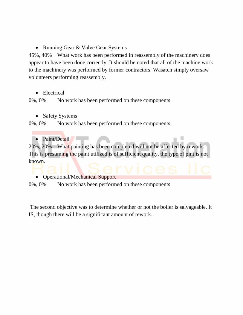
• Running Gear & Valve Gear Systems
45%, 40% What work has been performed in reassembly of the machinery does
appear to have been done correctly. It should be noted that all of the machine work
to the machinery was performed by former contractors. Wasatch simply oversaw
volunteers performing reassembly.
• Electrical
0%, 0% No work has been performed on these components
• Safety Systems
0%, 0% No work has been performed on these components
• Paint/Detail
20%, 20% What painting has been completed will not be affected by rework.
This is presuming the paint utilized is of sufficient quality, the type of pint is not
known.
• Operational/Mechanical Support
0%, 0% No work has been performed on these components
The second objective was to determine whether or not the boiler is salvageable. It
IS, though there will be a significant amount of rework..

Applicable Codes
FRA:
The Federal Railroad Administration, the regulatory entity which has jurisdiction
over the K&T 14. Regulatory information is contained within 49 CFR Part 230.
Specifically stated within this component of the CFR is the following:
§ 230.29 Inspection and repair.
(a)Responsibility. The steam locomotive owner and/or operator shall inspect and
repair all steam locomotive boilers and appurtenances under their control. They
shall immediately remove from service any boiler that has developed cracks in the
barrel. The steam locomotive owner and/or operator shall also remove the boiler
from service whenever either of them, or the FRA inspector, considers it necessary
due to other defects.
(b)Repair standards.
(1) All defects disclosed by inspection shall be repaired in accordance with
accepted industry standards - which may include established railroad practices, or
NBIC or API established standards - before the steam locomotive is returned to
service. The steam locomotive owner and/or operator shall not return the steam
locomotive boiler or appurtenances to service unless they are in good condition
and safe and suitable for service.
(2) Any welding to unstayed portions of the boiler made pursuant to § 230.33 shall
be made in accordance with an accepted national standard for boiler repairs. The
steam locomotive owner and/or operator shall not return the steam locomotive
boiler or appurtenances to service unless they are in good condition and safe and
suitable for service.
While not explicitly stated, the FRA does recognize and often reference ASME
standards.

NBIC:
The National Board Inspection Code (NBIC) was first published in 1946 as a
guide for chief inspectors. It has become an internationally recognized standard,
adopted by most US and Canadian jurisdictions. The NBIC provides standards for
the installation, inspection, and repair and/or alteration of boilers, pressure vessels,
and pressure relief devices.
ASME:
The ASME Boiler & Pressure Vessel Code (BPVC) is an American Society of
Mechanical Engineers (ASME) standard that regulates the design and construction
of boilers and pressure vessels. The document is written and maintained by
volunteers chosen for their technical expertise. The American Society of
Mechanical Engineers works as an Accreditation Body and entitles independent
third parties such as verification, testing and certification agencies to inspect and
ensure compliance to the BPVC.

Locomotive Boiler Familiarity
The following images are provided for the purpose of lending visual aid in
understanding the location of the mentioned components.

This image provides a perspective as to the manner in which the boiler is
integrated into the locomotive.

Observed Defects
1) Rigid and Crown staybolts incorrectly installed.
The rigid bolts are installed utilizing a combination of filet welding and threading.
The FRA does not allow for the application of filet welded bolts on non-chinese
locomotives without prior written approval as it is not an accepted railroad practice
nor (until summer of 2017) is it allowed by the ASME.
Though the ASME does now allow filet welded installation, they must be applied
under specific criteria as laid forth in PL-30. Specifically, parts PL-30.4, PL-
30.4.2, and PL-30.4.4. This in turn violates CFR49 Part 230.29 (b) (1).
PL-30.4.2: A number of bolts do not
have sufficient projection through fire
side of the sheet to allow for 1/4” of
weld without consuming the end of the
bolt as prohibited by PW-19.2.
PL-30.4.4: All rigid and crown
staybolts which can be observed from
within the boiler have 1/8”+ clearance
between the bolt and the sheet. Double
allowable.

2) Flexible bolts installed via filet through torch cut holes which are
between 1/8” to 5/8” oversized. This violates PL-30.4.4, and also PW-
29.3.
PW-29.3: The surfaces left
behind (throughout the
firebox) by the torch cutting
are not free of torch scale or
slag (foreign material), and
are also notched and
consistently textured with
deep striations. This in turn
violates CFR49 Part 230.29
(b) (1). Hundreds such
locations exist.

The above depicts holes well in excess of Orange denotes 2” diameter
1/8” oversize on fluesheet torch cut holes.
Red denotes holes in excess of
¼” oversize in FR crownsheet

3) All New Holes for flexible sleeves thermally enlarged. Torch scale, slag,
gouges, and striations not removed prior to welding.
In addition to the violations to code consistent with PW-29.3, the accompanying
photos depict a portion of an original rigid bolt remaining alongside of (and partially
consumed by) a rough cut hole. This in turn violates CFR49 Part 230.29 (b) (1). This
boiler has approximately 300 flexible bolts.


4) Rivets do not meet the specifications set forth in ASTM A31-B
The tensile strength exceeds the maximum limit set forth by the A31 grade B
material specification. This in turn violates CFR49 Part 230.29 (b) (1), and NBIC
Section 3, S1.1.3.1 material specifications for locomotive boilers.


5) Interior Firebox Corners, Plate Misalignment, Lack of Full Penetration
Weld
PW-9.3.1 lays out permissible tolerances associated with sheet misalignment, the
maximum allowable is 25% of sheet thickness. Misalignment on the waterside of
the sheet are up to 83% or 5/16”. This in turn violates CFR49 Part 230.29 (b) (1).

PW-9.1. states that all welds are to be full penetration. It can be seen from the
above photos that there is no 1 in 3 blending of the above limit offset, and no sign
of weld coming through to the waterside of the plate. This in turn violates CFR49
Part 230.29 (b) (1).

6) A Portion Of The New Firebox Was Replaced With Flat Plate In A
Tight Radius
A sharply radiused portion of the new firebox was cut out and replaced with a
piece of flat plate. This is contrary to O.E.M. design and violates railroad standard
practice, and NBIC code. PW-9.3.1 states that the “middle lines” of the plate are to
be aligned, these are not as one is radiused and the other straight. When replacing a
portion of any boiler it is to replaced “in kind” to the original. This in turn violates
CFR49 Part 230.29 (b) (1).

7) “All Thread” Utilized As Staybolt Material
All of the staybolts between the belly braces and rear tubesheet consist of an “all
thread” material. ASME and NBIC specify that acceptable staybolt materials shall
comply with SA36 or SA675. Commercially made “all thread” does not comply
with either of these material specifications. This style of belly brace is designed to
utilize a flexible staybolt, there is a socket beneath the nuts which do not generally
contact the brace. This in turn violates CFR49 Part 230.29 (b) (1).

8) “All Thread” Utilized As Studs At 62 Locations Around The Barrel
And Firebox, Installed Into Torch Cut Holes
A commercial grade “all thread” material was utilized. There are no commercially
available “all thread” materials which are approved for welding into steam boilers.
The pieces of “all thread” were installed into torch cut holes. Code does not allow
for the welding of threads into a pressure vessel. This in turn violates CFR49 Part
230.29 (b) (1).

There are multiple locations around
the pressure vessel at which these
incorrectly applied studs are pressure
retaining. These are especially
concerning because when they do fail
there would be a sudden and uncontrolled release of steam. Due to the proximity of
the effected attachments to crew or the public, it is almost guaranteed scalding
injuries would occur.

9) Bolts Welded Into The Vessel As Studs For Attachment Of Delivery
Tee, Bolts Installed Through Torch Cut Holes
The issues with the bolts are no different than those of the studs, the use of bolts is
not a compliant practice. The bolts are installed through torch cut holes, leaving
behind gouging and striations. As discussed above, PW-29.3 prohibits these
physical conditions. The integrity of the reinforcing ring has been compromised.
This in turn violates CFR49 Part 230.29 (b) (1).
10) Non-compliant Application Of Nozzles And Scab Patches To Belly
Of Barrel
Reinforcing liners for the application of washout plug sleeves were applied via
filet weld after the tubes were installed. Holes were then cut for application of the
sleeves (referred to as nozzles), though the nozzles appear to have only been
welded to the liner. This is determined via exterior inspection revealing inadequate
beveling around the nozzle for full penetration 1 ¼” of material, and a borescope
inspection which shows a seem on the waterside of the nozzle.
These conditions are in contradiction to PW-16.1
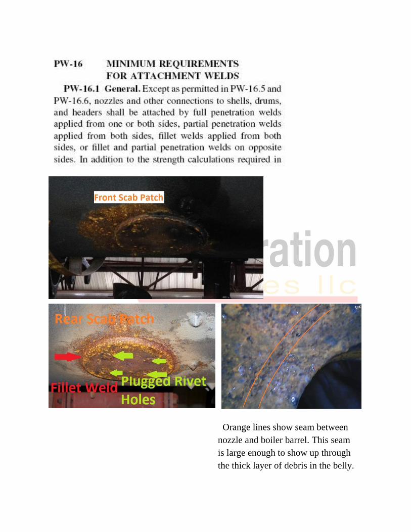
Orange lines show seam between
nozzle and boiler barrel. This seam
is large enough to show up through
the thick layer of debris in the belly.
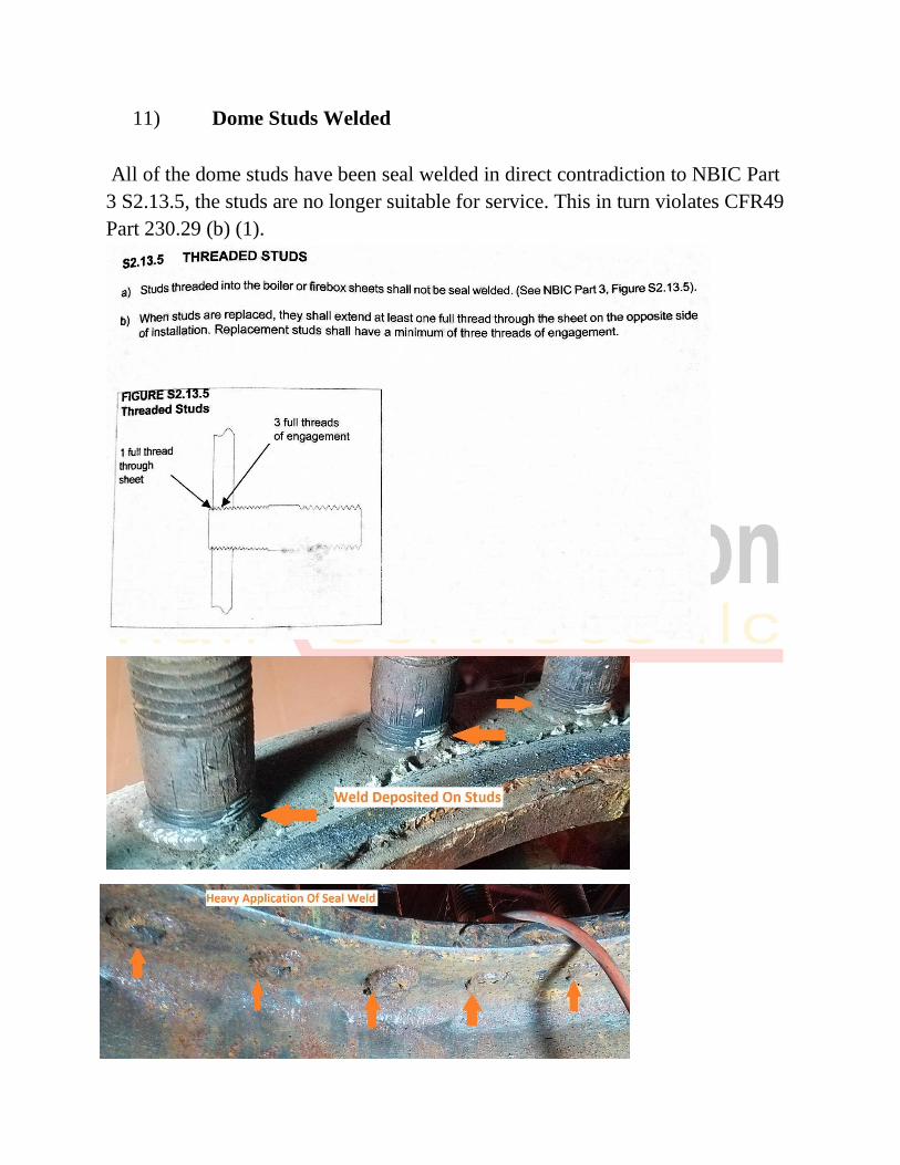
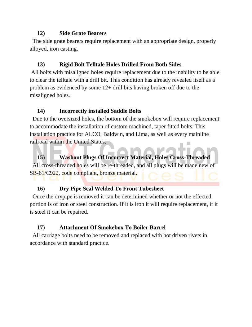
11) Dome Studs Welded
All of the dome studs have been seal welded in direct contradiction to NBIC Part
3 S2.13.5, the studs are no longer suitable for service. This in turn violates CFR49
Part 230.29 (b) (1).

12) Side Grate Bearers
The side grate bearers consist of thin steel fabrications. Standard practice dictates
these to be heavy/solid iron castings of an appropriate alloy. This is required as
steel will burn, warp, and quickly fail.

13) Rigid Bolt Telltale Holes Drilled From Both Sides
The telltale holes are drilled from both ends of the bolt, many do not lineup from
one end to the other. Numerous bolts exhibit holes which are misaligned by ½ of
the hole diameter. This results in an inability to clear telltales in accordance with
CFR 49 230.38 (c) as is evidenced by numerous broken drill bits left behind in the
installed bolts. Bolts must be cleared so that when a bolt breaks, steam/water can
be observed escaping.

14) Incorrectly installed Saddle Bolts
The saddle bolts (bolts connecting the smokebox to the cylinder casting) are of
incorrect design and installed incorrectly. Railroad standard practice calls for the
saddle bolts to be of a taper fitted type bolt, these are commercially available,
straight shank, black oxide bolts. The bolts were installed through dramatically
oversized torch cut holes, versus the tight and machined fit standard practice calls
for. Additionally, standard practice dictates that bolts be installed from the inside
with nuts on the exterior, these bolts are installed upside down.
15) Washout Plugs Of Incorrect Material, Holes Cross-Threaded
All washout plugs are machined from a steel material. It is a well-accepted fact
that steel plugs will seize in their threaded hole when utilized in locomotive boiler
service, standard practice dictates the use of SB-61 bronze. Several holes are
severely cross threaded.

16) Dry Pipe Seal Welded To Front Tubesheet
The front end of the drypipe has been seal welded to the front tubesheet. This is
contrary to railroad standard practice as the drypipe is to be a removable
component.
17) Attachment Of Smokebox To Boiler Barrel
The boiler and smokebox have been joined by generic/hardware store carriage
bolts. Standard railroad practice calls for attachment via rivets. The exterior of the
bolts were heated and driven with an air hammer, presumably to make them look
more like rivets. This Joint will allow movement between the boiler and the
smokebox which will ultimately lead to cracking in the frame.

18) No Flexible Bolts In Backhead
The firebox of the 14’s boiler has received *most* of an AAR flexible staybolt
pattern. While upgrading a locomotive boiler to having a full AAR flexible bolt
pattern is a railroad standard practice, and highly advisable, it must be done in full.
In this case, the backhead received no flexible bolts. The result of this incomplete
installation will result a high occurrence of broken bolts around the backhead due
to allowance for additional movement along the ends of the sidesheets.
19) The First Three Rows Of The Crownsheet Bolt Holes
The first three rows of bolts had dramatically oversized holes (double bolt
diameter, several of which are still visible. Those still visible are approximately
7/16” oversized. Approximately 18 bolts have been removed to allow for the weld
build up of the holes. This was done so poorly that the original enlarged diameter
is still visible at multiple locations as well as pockets of slag within the welds.
While it is unclear as to why, the water side surface of the sheet has been built up
with weld. The thickness of the .375” sheet has increased to over .625”. I conclude
that this was done for the purpose of hiding sheet misalignment. The welding rod
utilized for this welding is not appropriate for use on pressure vessels.


20) Crown To Doorsheet Fit-up
The welded joint between the crownsheet and doorsheet was found to be far in
excess of ASME/NBIC parameters. These standards were discussed above
regarding the corners. In addition to the sheet misalignment, the accompanying
photo depicts torch cut holes, and threads present in the welds joining the bolts to
the crownsheet.
What was unable to be adequately captured in photos is the amount of
misalignment. At the center of the crownsheet it as almost full sheet thickness. In
order to achieve this fit up, only the leading edge of the doorsheet knuckle was
bent upward. When the new sheet was made the knuckle was bent about 10
degrees beyond 90 to allow for fit up. Instead of just the leading edge, the
transition in
alignments should
have flowed back into
the radius.

21) Material Test Reports (MTR’s)
No MTR’s are present for any of the material which was installed into the boiler.
The materials lacking MTR’s consist of the firebox sheets, rigid bolts, crown bolts,
rivets, tubes, caps, sleeves, and stud material.

Corrective Actions
1) Rigid and Crown staybolts incorrectly installed.
Due to the incorrect method of installation, all crown staybolts, and rigid staybolts
must be removed and replaced. In order to properly install new staybolts, the
firebox sheets must also be replaced due to the oversized, and damaged holes.
2) Flexible bolts installed via filet through torch cut holes which are
between 1/8” to 5/8” oversized.
Due to the incorrect method of installation, all flexible staybolts must be removed
and replaced. In order to properly install new staybolts, the firebox sheets must
also be replaced due to the oversized, and damaged holes.
3) Holes for flexible sleeves thermally enlarged. Torch scale, slag, gouges,
and striations not removed prior to welding.
Once all flexible bolts are removed, the accompanying sleeves will then need to
be removed. This will facilitate reclaiming the holes in the external firebox sheets
via welding following proper hole preparation.
4) Rivets do not meet the specifications set forth in ASTM A31-B
All rivets must be replaced with rivets made of code material. This would be done
in conjunction with replacing the interior firebox sheets to correct for defects 1,
and 2.
5) Interior Firebox Corners, Plate Misalignment, Lack of Full Penetration
Weld
The defects associated with the corners require their replacement. This will be
done in conjunction with items 1, 2, and 4.
6) A Portion Of The New Firebox Was Replaced With Flat Plate In A
Tight Radius
This defect requires the replacement of the flat plate with a piece of material
formed to properly match the centerline of the adjoining plate. This will be
corrected in conjunction with items 1, 2, and 3.

7) “All Thread” Utilized As Staybolt Material
These pieces of non-code, improper design material will be replaced with flexible
staybolts. This will be accomplished in conjunction with items 1, 2, 3, and 4.
8) “All Thread” Utilized As Studs At 62 Locations Around The Barrel
And Firebox, Installed Into Torch Cut Holes
All “all thread” studs must be replaced with studs of a proper material, and
utilizing a proper installation practice. There are 3 repair options and they would
need to be discussed with the FRA to determine which they are most comfortable
with, though all 3 do meet code requirements. The repair options are: 1) Full
penetration welded installation of code material, 2) Weld build up and re-tapping
of all effected holes, 3) Replace the boiler barrel with one of new, all welded
construction.
While the 3rd option may seem intimidating, it is relatively simple and may well
be the fastest and most cost-effective option. In the course of replacing the boiler
barrel items would be addressed with new construction rather than rework.
9) Bolts Welded Into The Vessel As Studs For Attachment Of Delivery
Tee, Bolts Installed Through Torch Cut Holes
The reinforcing ring requires replacement to correct for the torch cut holes.
Depending upon the appearance of the fluesheet once the non-code material is
removed, a patch may be required.
10) Non-compliant Application Of Nozzles And Scab Patches To Belly
Of Barrel
The “scab patches” need to be removed need to be removed from the boiler barrel
to facilitate liners of riveted attachment in keeping with OEM construction.
Following the application of the liners, Huron washout sleeves will be applied in
accordance with OEM practice which consists of threading them into the barrel.
11) Dome Studs Welded
All dome studs require replacement due to the seal welding.
12) Side Grate Bearers
The side grate bearers require replacement with an appropriate design, properly
alloyed, iron casting.
13) Rigid Bolt Telltale Holes Drilled From Both Sides
All bolts with misaligned holes require replacement due to the inability to be able
to clear the telltale with a drill bit. This condition has already revealed itself as a
problem as evidenced by some 12+ drill bits having broken off due to the
misaligned holes.
14) Incorrectly installed Saddle Bolts
Due to the oversized holes, the bottom of the smokebox will require replacement
to accommodate the installation of custom machined, taper fitted bolts. This
installation practice for ALCO, Baldwin, and Lima, as well as every mainline
railroad within the United States.
15) Washout Plugs Of Incorrect Material, Holes Cross-Threaded
All cross-threaded holes will be re-threaded, and all plugs will be made new of
SB-61/C922, code compliant, bronze material.
16) Dry Pipe Seal Welded To Front Tubesheet
Once the drypipe is removed it can be determined whether or not the effected
portion is of iron or steel construction. If it is iron it will require replacement, if it
is steel it can be repaired.
17) Attachment Of Smokebox To Boiler Barrel
All carriage bolts need to be removed and replaced with hot driven rivets in
accordance with standard practice.

18) No Flexible Bolts In Backhead
While correcting items 1, 2, 4, and 5, 2 rows of flexible sleeves (and then bolts)
need to be installed around the perimeter of the backhead staybolt pattern. This is
required as a component of the AAR flexible pattern installed throughout the other
appropriate areas of the firebox. Without the installation of these, the rigid bolts
would break on a very regular basis.
19) The First Three Rows Of The Crownsheet Bolt Holes
These torch-cut, oversized, and then incorrectly repaired holes require
replacement of the effected sheet. This will be accomplished in conjunction with
items 1, and 2.
20) Crown To Doorsheet Fit-up
This defect requires replacement of either the doorsheet or the crownsheet. This
will be accomplished in conjunction with items 1, 2, 4, 5, and 6.
21) Material Test Reports (MTRs)
Any new installation material, for which a material test report does not exist, must
be replaced. Currently, there are no MTRs available for the staybolts, firebox
sheets, flexible sleeves or caps, flues, rivets, etc.
At this point, even if MTRs were made available, there is no “chain of custody”
which could show that the MTRs are applicable to the material which was
installed. All recently installed material must then be replaced.
Corrective Costs
The cost associated with repairing these defects will be approximately 30% more
than what has currently been invested into creating them. This is due to the
required labor associated with the disassembly, repair of base material, and re-
fabrication of new firebox components.