kalypso installation planning guide - grass valley
TRANSCRIPT

KalypsoVIDEO PRODUCTION CENTER
Installation Planning Guide
071061910JUNE 2004

2 Kalypso Installation Planning Guide
Contacting Grass Valley
Copyright © Thomson Broadcast and Media Solutions All rights reserved.
Grass Valley Web Site
The www.thomsongrassvalley.com web site offers the following:
Online User Documentation
— Current versions of product catalogs, brochures, data sheets, ordering guides, planning guides, manuals, and release notes in .pdf format can be downloaded.
FAQ Database
— Solutions to problems and troubleshooting efforts can be found by searching our Frequently Asked Questions (FAQ) database.
Software Downloads
— Software updates, drivers, and patches can be down-loaded.
Region Voice Fax Address Web Site
North America (800) 547-8949Support: 530-478-4148
Sales: (530) 478-3347Support: (530) 478-3181
Grass ValleyP.O. Box 599000Nevada City, CA 95959-7900 USA
www.thomsongrassvalley.com
Pacific Operations +852-2585-6688Support: 852-2585-6579
+852-2802-2996
U.K., Asia, Middle East +44 1753 218 777 +44 1753 218 757
France +33 1 45 29 73 00
Germany, Europe +49 6150 104 782 +49 6150 104 223

ContentsSection 1 — Introduction . . . . . . . . . . . . . . . . . . . . . . . . . . . . . . . . . . . . . . . . . . . . . . . . . 5
Kalypso Video Production Center . . . . . . . . . . . . . . . . . . . . . . . . . . . . . . . . . . . . . . . . 5Standard Kalypso System Components . . . . . . . . . . . . . . . . . . . . . . . . . . . . . . . . . . . 6
Control Surface . . . . . . . . . . . . . . . . . . . . . . . . . . . . . . . . . . . . . . . . . . . . . . . . . . . . . . 6Video Processing Frame . . . . . . . . . . . . . . . . . . . . . . . . . . . . . . . . . . . . . . . . . . . . . . . 7
Kalypso System Options . . . . . . . . . . . . . . . . . . . . . . . . . . . . . . . . . . . . . . . . . . . . . . . . 7Video Processor Frame Options . . . . . . . . . . . . . . . . . . . . . . . . . . . . . . . . . . . . . . . . 7
Kalypso Classic Frame Only Options . . . . . . . . . . . . . . . . . . . . . . . . . . . . . . . . . . 8Kalypso HD Frame Only Options . . . . . . . . . . . . . . . . . . . . . . . . . . . . . . . . . . . . . 8
Control Surface Options . . . . . . . . . . . . . . . . . . . . . . . . . . . . . . . . . . . . . . . . . . . . . . . 8Specifications . . . . . . . . . . . . . . . . . . . . . . . . . . . . . . . . . . . . . . . . . . . . . . . . . . . . . . . . . . 9
Kalypso Classic, HD, and Duo Systems. . . . . . . . . . . . . . . . . . . . . . . . . . . . . . . . . . 9Kalypso Classic System . . . . . . . . . . . . . . . . . . . . . . . . . . . . . . . . . . . . . . . . . . . . . . 10Kalypso HD and Duo Systems . . . . . . . . . . . . . . . . . . . . . . . . . . . . . . . . . . . . . . . . 12
Section 2 — Kalypso Control Surfaces . . . . . . . . . . . . . . . . . . . . . . . . . . . . . . . . . 15Control Surface Components . . . . . . . . . . . . . . . . . . . . . . . . . . . . . . . . . . . . . . . . . . . 15
4-M/E Control Surface . . . . . . . . . . . . . . . . . . . . . . . . . . . . . . . . . . . . . . . . . . . . . . . 152-M/E Control Surface . . . . . . . . . . . . . . . . . . . . . . . . . . . . . . . . . . . . . . . . . . . . . . . 161-M/E Control Surface . . . . . . . . . . . . . . . . . . . . . . . . . . . . . . . . . . . . . . . . . . . . . . . 16Removable Media Drives . . . . . . . . . . . . . . . . . . . . . . . . . . . . . . . . . . . . . . . . . . . . . 17
4-M/E and 2-M/E Main Panel Installation. . . . . . . . . . . . . . . . . . . . . . . . . . . . . . . . 17Cosmetic Bracket . . . . . . . . . . . . . . . . . . . . . . . . . . . . . . . . . . . . . . . . . . . . . . . . . . . . 184-M/E Main Panel . . . . . . . . . . . . . . . . . . . . . . . . . . . . . . . . . . . . . . . . . . . . . . . . . . . 202-M/E Main Panel . . . . . . . . . . . . . . . . . . . . . . . . . . . . . . . . . . . . . . . . . . . . . . . . . . . 22
1-M/E Main Panel Installation . . . . . . . . . . . . . . . . . . . . . . . . . . . . . . . . . . . . . . . . . . 24Local Aux Panel Installation . . . . . . . . . . . . . . . . . . . . . . . . . . . . . . . . . . . . . . . . . . . . 26
Mounting Brackets . . . . . . . . . . . . . . . . . . . . . . . . . . . . . . . . . . . . . . . . . . . . . . . . . . 27Power Cabling . . . . . . . . . . . . . . . . . . . . . . . . . . . . . . . . . . . . . . . . . . . . . . . . . . . . . . 28
4-M/E Systems . . . . . . . . . . . . . . . . . . . . . . . . . . . . . . . . . . . . . . . . . . . . . . . . . . . . 282-M/E Systems . . . . . . . . . . . . . . . . . . . . . . . . . . . . . . . . . . . . . . . . . . . . . . . . . . . . 28External Power Supply . . . . . . . . . . . . . . . . . . . . . . . . . . . . . . . . . . . . . . . . . . . . . 29
Menu Panel Installation . . . . . . . . . . . . . . . . . . . . . . . . . . . . . . . . . . . . . . . . . . . . . . . . 29Menu Panel Ventilation . . . . . . . . . . . . . . . . . . . . . . . . . . . . . . . . . . . . . . . . . . . . . . 30Recommended Mounting Location . . . . . . . . . . . . . . . . . . . . . . . . . . . . . . . . . . . . 30Available Mounting Brackets . . . . . . . . . . . . . . . . . . . . . . . . . . . . . . . . . . . . . . . . . 31Adaptable Mounting Bracket. . . . . . . . . . . . . . . . . . . . . . . . . . . . . . . . . . . . . . . . . . 32Adjustable Freestanding Console Bracket . . . . . . . . . . . . . . . . . . . . . . . . . . . . . . . 33Flush Mount Kit . . . . . . . . . . . . . . . . . . . . . . . . . . . . . . . . . . . . . . . . . . . . . . . . . . . . . 34Power Cabling . . . . . . . . . . . . . . . . . . . . . . . . . . . . . . . . . . . . . . . . . . . . . . . . . . . . . . 36
Optional System Components. . . . . . . . . . . . . . . . . . . . . . . . . . . . . . . . . . . . . . . . . . . 37Remote Aux Panels . . . . . . . . . . . . . . . . . . . . . . . . . . . . . . . . . . . . . . . . . . . . . . . . . . 37
24-Crosspoint Remote Aux Panels . . . . . . . . . . . . . . . . . . . . . . . . . . . . . . . . . . . 3732-Crosspoint Remote Aux Panels . . . . . . . . . . . . . . . . . . . . . . . . . . . . . . . . . . . 40
Shot Box . . . . . . . . . . . . . . . . . . . . . . . . . . . . . . . . . . . . . . . . . . . . . . . . . . . . . . . . . . . 42
Kalypso Installation Planning Guide 3

Contents
Installation . . . . . . . . . . . . . . . . . . . . . . . . . . . . . . . . . . . . . . . . . . . . . . . . . . . . . . . 42Cabling . . . . . . . . . . . . . . . . . . . . . . . . . . . . . . . . . . . . . . . . . . . . . . . . . . . . . . . . . . 44
Pinouts . . . . . . . . . . . . . . . . . . . . . . . . . . . . . . . . . . . . . . . . . . . . . . . . . . . . . . . . . . . . . . 454- and 2-M/E Main Control Panel . . . . . . . . . . . . . . . . . . . . . . . . . . . . . . . . . . . . . 451-M/E Main Control Panel . . . . . . . . . . . . . . . . . . . . . . . . . . . . . . . . . . . . . . . . . . . 45Menu Panel . . . . . . . . . . . . . . . . . . . . . . . . . . . . . . . . . . . . . . . . . . . . . . . . . . . . . . . . 46
Section 3 — Kalypso Classic Frame . . . . . . . . . . . . . . . . . . . . . . . . . . . . . . . . . . . 47Kalypso Classic Video Processor Frame . . . . . . . . . . . . . . . . . . . . . . . . . . . . . . . . . . 47
SD Video Processor Frame Options . . . . . . . . . . . . . . . . . . . . . . . . . . . . . . . . . . . . 51Video Processor Power Supply Frame . . . . . . . . . . . . . . . . . . . . . . . . . . . . . . . . . 51
Typical Kalypso Classic System Video Cabling. . . . . . . . . . . . . . . . . . . . . . . . . . . . 53Kalypso Classic System Control Cabling . . . . . . . . . . . . . . . . . . . . . . . . . . . . . . . . . 54
4-M/E Kalypso Classic System. . . . . . . . . . . . . . . . . . . . . . . . . . . . . . . . . . . . . . . . 542-M/E Kalypso Classic System. . . . . . . . . . . . . . . . . . . . . . . . . . . . . . . . . . . . . . . . 55Cables Provided . . . . . . . . . . . . . . . . . . . . . . . . . . . . . . . . . . . . . . . . . . . . . . . . . . . . 56LAN Requirements. . . . . . . . . . . . . . . . . . . . . . . . . . . . . . . . . . . . . . . . . . . . . . . . . . 56
Ethernet Switches and Hubs . . . . . . . . . . . . . . . . . . . . . . . . . . . . . . . . . . . . . . . . 57Kalypso Classic Video Timing and Delay . . . . . . . . . . . . . . . . . . . . . . . . . . . . . . . . 60Optional Kalypso Classic System Components. . . . . . . . . . . . . . . . . . . . . . . . . . . . 61
Emergency Bypass . . . . . . . . . . . . . . . . . . . . . . . . . . . . . . . . . . . . . . . . . . . . . . . . . . 61Emergency Bypass Frame . . . . . . . . . . . . . . . . . . . . . . . . . . . . . . . . . . . . . . . . . . 62Frame Restrictions. . . . . . . . . . . . . . . . . . . . . . . . . . . . . . . . . . . . . . . . . . . . . . . . . 63Power Supply Options . . . . . . . . . . . . . . . . . . . . . . . . . . . . . . . . . . . . . . . . . . . . . 63
8950ADC Module - 4:4:4 Chroma Key Processing. . . . . . . . . . . . . . . . . . . . . . . . 63Overview . . . . . . . . . . . . . . . . . . . . . . . . . . . . . . . . . . . . . . . . . . . . . . . . . . . . . . . . 63Kalypso Solution . . . . . . . . . . . . . . . . . . . . . . . . . . . . . . . . . . . . . . . . . . . . . . . . . . 64
SD Video Processor Frame Pinouts . . . . . . . . . . . . . . . . . . . . . . . . . . . . . . . . . . . . . . 65Control I/O Module. . . . . . . . . . . . . . . . . . . . . . . . . . . . . . . . . . . . . . . . . . . . . . . . . 65Reference In Module . . . . . . . . . . . . . . . . . . . . . . . . . . . . . . . . . . . . . . . . . . . . . . . . 69
Section 4 — Kalypso HD Frame . . . . . . . . . . . . . . . . . . . . . . . . . . . . . . . . . . . . . . . . 71HD Video Processor Frame. . . . . . . . . . . . . . . . . . . . . . . . . . . . . . . . . . . . . . . . . . . . . 71
HD Video Processor Frame Hardware Options. . . . . . . . . . . . . . . . . . . . . . . . . . 75Emergency Bypass Option. . . . . . . . . . . . . . . . . . . . . . . . . . . . . . . . . . . . . . . . . . 75
Video Processor Power Supply Frame . . . . . . . . . . . . . . . . . . . . . . . . . . . . . . . . . 75Typical Kalypso HD System Video Cabling . . . . . . . . . . . . . . . . . . . . . . . . . . . . . . 76Kalypso HD System Control Cabling . . . . . . . . . . . . . . . . . . . . . . . . . . . . . . . . . . . . 77
4-M/E Kalypso HD System. . . . . . . . . . . . . . . . . . . . . . . . . . . . . . . . . . . . . . . . . . . 772-M/E Kalypso HD System. . . . . . . . . . . . . . . . . . . . . . . . . . . . . . . . . . . . . . . . . . . 78Cables Provided . . . . . . . . . . . . . . . . . . . . . . . . . . . . . . . . . . . . . . . . . . . . . . . . . . . . 79Kalypso HD LAN Requirements . . . . . . . . . . . . . . . . . . . . . . . . . . . . . . . . . . . . . . 79
Kalypso Control Surface Facility LAN. . . . . . . . . . . . . . . . . . . . . . . . . . . . . . . . 80Connecting Kalypso to An Existing LAN . . . . . . . . . . . . . . . . . . . . . . . . . . . . . 81
HD Video Processor Frame Pinouts . . . . . . . . . . . . . . . . . . . . . . . . . . . . . . . . . . . . . 83
4 Kalypso Installation Planning Guide

Section 1Introduction
Kalypso Video Production CenterThe Kalypso Video Production Center features powerful digital video switching, mixing, and keying with E-MEM, plus integrated control of other production devices such as external effects systems, VTRs, DDRs, and facility routers. The architecture of the system provides a flexible, quickly reconfigurable system able to meet the demanding requirements of live production and post production applications.
The Kalypso system includes a variety of components that can be pur-chased in different combinations to meet varying requirements. Refer to the Kalypso Ordering Guide for information on the many hardware and software options available. Online documentation is available on the Grass Valley Group web site. The URL for the Grass Valley Group website is found on the copyright page at the front of this manual.
Kalypso Installation Planning Guide 5

Section 1 — Introduction
Standard Kalypso System ComponentsA Kalypso system consists of a Control Surface, a Video Processor frame, Video Processor Power Supply frame, and removable media drives. Figure 1 shows a standard 4-M/E Kalypso system. Several of the system components depicted are also common to 2-M/E systems.
Figure 1. 4-M/E System Components
Control SurfaceThe modular design of Kalypso control panels provides flexibility for mounting component panels in various environments, and allows the addition of specialized accessory control panels. A group of panels avail-able to a single operator is called a Control Surface. Kalypso Control Surface components include:
• Main panel, which provides the operator with real time control of the system. 4-M/E, 2-M/E, and 1-M/E Main panels are available.
• Menu panel, which provides additional system controls that generally do not require real time adjustment.
• Local Aux panel, which provides control of Kalypso system Aux buses and some other system components. 4-M/E Kalypso systems have a separate Local Aux panel. Local Aux panel functionality is incorpo-rated into the Kalypso 2-M/E panel.
• Removable media drives (CD-ROM and Zip Disk) for software loading and data storage.
Different Kalypso systems can have different Control Surface components.
4-M/EMain Panel
Video Processor Frame
Video ProcessorPower Supply Frame
Local Aux PanelMenu Panel
Control Surface
RemovableMediaDrives
0619
_08_
01_r
0
Bypass Active
Assign
EmergencyBypass
Select Source
6 Kalypso Installation Planning Guide

Kalypso System Options
Video Processing FrameTwo different Video Processing frames are available. The Kalypso Classic frame operates with standard definition video only. The Kalypso HD frame can be switched between either high definition or standard definition video operation. The Kalypso Duo system uses the Kalypso HD frame for only standard definition video operation. An optional upgrade is available to convert a Kalypso Duo system into a fully functional Kalypso HD system that also supports high definition video.
Kalypso Video Processing frames do not perform input video format con-versions. The video sources connected to the Kalypso frame must be com-patible with the selected operating format and reference signal.
Each type of Video Processing frame can be configured as either a 4-M/E system or a 2-M/E system, depending on the number of Mix Effects and other modules installed in the frame. In addition, a 2-M/E frame can be upgraded to a 3-M/E system or 4-M/E system.
The Video Processor frame has a separate power supply. The same type of power supply frame is used for the SD and HD Kalypso frames.
Kalypso System OptionsKalypso system options can be categorized as Video Processor frame options and Control Surface options. Frame options add basic capabilities to the system, while the Control Surface options offer flexibility in control-ling the Kalypso system. A general description of these options follows. Refer to the Kalypso Ordering Guide for details.
Video Processor Frame Options• Transform Engine, adds three channels of video/key digital transform
effects. Up to two Transform Engines can be installed,
• Kurl (for Transform Engine), with Splits and Mirrors,
• SuperStill, adds advanced Still Store capabilities with two inputs, eight outputs, animation, disk storage, and includes the Still Store Loader application for image transfer to and from PCs,
• KlipCache (for SuperStill), increases cache storage capacity to about 1800 frames.
• Chromatte Advanced Dual Chroma Keyer, adds two floating chroma keyers, able to be assigned to any keyer in the system at any time. Up to eight dual chroma keyers (16 total) can be installed,
Kalypso Installation Planning Guide 7

Section 1 — Introduction
• FlexiKey Programmable Clean Feed, allows creation of two indepen-dent program streams, using key substitution, through one or more M/Es,
• DoubleTake, allows creation of two completely independent M/E com-posites in a single M/E, producing the power of eight M/Es in a 4-M/E system,
• Machine control of Profile VDR channels,
• Machine control of VTRs, and
• Redundant Video Processor power supply,
Kalypso Classic Frame Only Options• Input modules (16 inputs each), up to 80 total inputs,
• Output modules (8 outputs each), up to 48 total outputs,
• Additional Tally Module, adding 64 more tally contacts,
• Emergency Bypass system, with two keyers and program and preview outputs,
• 2-M/E to 4-M/E upgrade, and
• 2-M/E to 3-M/E upgrade.
Kalypso HD Frame Only Options• M/E upgrade (upgrades 2-M/E to 3-M/E or 3-M/E to 4-M/E system,
purchase two to upgrade from 2-M/E to 4-M/E),
• Additional 15 inputs, up to 90 total inputs, and
• Kalypso Duo to Kalypso HD upgrade.
Control Surface Options• Source Name displays for M/E 1, 2, and 3,
• 24 and 32-Crosspoint Remote Aux panels,
• Shot Box, and
• Redundant Main panel power supply.
8 Kalypso Installation Planning Guide

Specifications
Specifications
Kalypso Classic, HD, and Duo Systems
Table 1. Kalypso Mechanical Specifications
Component Depth Width Height Weight a
a All weights approximate.
Rack Units
Standard
Video Processor Frame - Classic 586 mm / 23.06 in.b
b Allow an extra 102 mm (4 in.) for cable.
483 mm / 19 in. 578 mm / 22.75 in. 75.75 kg / 167 lb 13
Video Processor Frame - HD & Duo 523 mm / 20.56 in.b 483 mm / 19 in. 578 mm / 22.75 in. 46 kg / 100 lb 13
4-M/E Main Control Panel 624 mm / 24.58 in.c, d
c Allow a minimum of 152 mm (6 in.) of clear space at the rear of the Main panel below the mounting surface for proper cable clearance andair flow. Allow an extra 203 mm (8 in.) to 254 mm (10 in.) of mounting surface behind the Main panel for peripheral components (e.g., LocalAux panel). d Indicated measurement is for lid. Refer to installation detail for tub measurements.
1410 mm / 55.5 in.d 189 mm / 7.44 in.e
e Add 13 mm (0.5 in.) for rubber feet on bottom of tub if required. Indicated measurement is from bottom surface of tub to top surface of lid.
86 kg / 189 lb N/A
2-M/E Main Control Panel 483 mm / 19.0 in.c, d 1252 mm / 49.31in.d 207 mm / 8.3 in.e 63 kg / 138 lb N/A
1-M/E Main Control Panel 400 mm / 15.73 in.f
f Indicated measurement is for top surface of panel. Refer to installation detail for tub measurements.
458 mm / 18.02 in.g
g Indicated measurement is for top surface of panel. Add 27 mm (1.06 in.) for mounting brackets.
101 mm / 3.99 in.h
h Indicated measurement is from bottom surface of tub to top surface of panel.
11.34 kg / 25 lb 9
Local Aux Panel 99 mm / 3.9 in. 668 mm / 26.3 in. 183 mm / 7.2 in. 15.88 kg / 35 lb N/A
Menu Panel 109 mm / 4.30 in. 375 mm / 14.75 in.i
i Allow an extra 147 mm (5.8 in.) clearance for the CD-ROM and fan exhaust.
257 mm / 10.1 in. 7.7 kg / 17 lb 7j
j Optional Flush Mount kit.
Video Processor Power Supply Frame 406 mm / 16.0 in. 483 mm / 19.0 in. 89 mm / 3.5 in. 15 kg / 33 lbk
k Includes optional redundant power supply module.
2
Options
KAL-24AUX1 Remote Aux Panel 51 mm / 2.0 in. 483 mm / 19.0 in. 45 mm / 1.75 in. 1.02 kg / 2.25 lb 1
KAL-24AUX2 Remote Aux Panel 64 mm / 2.5 in. 483 mm / 19.0 in. 89 mm / 3.5 in. 2.04 kg / 4.5 lb 2
KAL-24AUX3 Remote Aux Panel 64 mm / 2.5 in. 483 mm / 19.0 in. 133 mm / 5.25 in. 3.06 kg / 6.75 lb 3
KAL-32AUX1 Remote Aux Panel 133 mm / 5.25 in. 483 mm / 19.0 in. 44 mm / 1.75 in. 0.93 kg / 2.06 lb 1
KAL-32AUX2 Remote Aux Panel 108 mm / 4.25 in. 483 mm / 19.0 in. 89 mm / 3.5 in. 1.02 kg / 2.25 lb 2
Emergency Bypass Framel
l Available only for Kalypso Classic systems.
356 mm / 14 in. 483mm / 19.0 in. 89 mm / 3.5 in. 5.17 kg / 11.4 lbm
m Weight with no modules, 1 power supply. 5.71 kg/12.6 lb with no modules, 2 power supplies.
2
Shot Box 172 mm/ 6.75 in. 216 mm / 8.5 in. 51 mm/ 2 in. 1.22 kg/2.7 lb N/A
Kalypso Installation Planning Guide 9

Section 1 — Introduction
Kalypso Classic SystemTable 2. Kalypso Classic General Specifications
Power
Video Processor Frame Power Supply
PowerConsumption
100-125 VAC or 200-250 VAC autorange, 50-60 Hz power factor corrected
700 W (no options), 850 W (typical), 1200 W (maximum)
Main Panel Power Supply
PowerConsumption
100-125 VAC or 200-250 VAC autorange 50-60 Hz power factor corrected
4-M/E: 600 W (typical), 800 W (maximum) 2-M/E: 600 W (maximum)
Local Aux Panel Power Supply
PowerConsumption
100-125 VAC or 200-250 VAC
Usually powered through Main Panel, 50 W if powered externally.
Environmental
Temperature Range
Frame, Local Aux Panel, Menu Panel
Ambient temperature for specifications: 20º to 30º C (68º to 86º F)Ambient temperature for operation: 0º to 40º C (32º to 104º F)
Main Control Panel Specification: 20º to 30º C (68º to 86º F)Operational: 0º to 35º C (32º to 95º F)
Relative Humidity Up to 95% (non-condensing)
Table 3. Kalypso Classic System Specifications
Video Standard - Conforms to SMPTE RP-259M
Serial Digital Video Inputs
Number 16 standard, 64 optional, 80 total (non-looping)
Type of Connectors 75 ohm BNC, (SMPTE 259M)
Nominal Amplitude 800 mV peak-to-peak terminated
Return Loss > 15 dB, 5 MHz to 270 MHz
Channel Coding Conforms to SMPTE RP-259M
Ancillary Data Blanked or passed from A background to M/E outputs (includes reentries)
Input Impedance 75 ohm
Maximum Cable Length Equalized (Belden 8281 type cable) 225 m (738 ft)
Number of Bits 10
Serial Digital Video Outputs
Number8 standard video (2 connectors each), or up to 4 video/key pairs of Effects Send. 4-M/E: An additional 40 standard video (2 connectors each) are optional (32 standard video for 2-M/E)
Type of Connectors 75 ohm BNC, self terminating (SMPTE 259M)
Amplitude 800 mV peak-to-peak across 75 ohm ± 10% (SMPTE 259M)
Return Loss > 15 dB, 5 MHz to 270 MHz
Rise and Fall Times (between 20% and 80% amplitude points) Between 400 picosecond and 1.5 nanosecond across 75 ohm termination
Timing Jitter 0.2 UI (SMPTE RP184-1996 method)
Output Impedance 75 ohm
DC Offset on Output < 50 mV across 75 ohm termination
Number of Bits 10
Number of Connectors per Output 2 BNC connectors per channel
Ancillary Data Included on the A program output of each M/E
10 Kalypso Installation Planning Guide

Specifications
Analog Reference Input
Black 525 (60 Hz) or 625 (50 Hz)
Connectors 2 BNC
Return Loss > 40 dB to 5 MHz
Impedance 75 ohm loop through
System Timing
Nominal Switcher Delay 53 µs
Serial Input Autotiming +/- 10 µs
Minimum Switcher Delay 43 µs
Maximum Switcher Delay 63 µs
Table 3. Kalypso Classic System Specifications - (continued)
Kalypso Installation Planning Guide 11

Section 1 — Introduction
Kalypso HD and Duo SystemsTable 4. Kalypso HD and Duo General Specifications
Power
Video Processor Frame Power Supply
PowerConsumption
100-125 VAC or 200-250 VAC autorange, 50-60 Hz power factor corrected
900 W (typical), 1200 W (maximum)
Main Panel Power Supply
PowerConsumption
100-125 VAC or 200-250 VAC autorange 50-60 Hz power factor corrected
4-M/E: 600 W (typical), 800 W (maximum) 2-M/E: 600 W (maximum)
Local Aux Panel Power Supply
PowerConsumption
100-125 VAC or 200-250 VAC
Usually powered through Main Panel, 50 W if powered externally.
Environmental
Temperature Range
Frame, Local Aux Panel, Menu Panel
Ambient temperature for specifications: 20º to 30º C (68º to 86º F)Ambient temperature for operation: 0º to 40º C (32º to 104º F)
Main Control Panel Specification: 20º to 30º C (68º to 86º F)Operational: 0º to 35º C (32º to 95º F)
Relative Humidity Up to 95% (non-condensing)
Vibration ASTM D 4728 Fig X1.1, table X1.1, Truck Profile
Table 5. Kalypso HD and Duo System Video Specifications
Video Standards
HD Mode SD Mode
1080i 29.97/30 SMPTE 274M Table 1-4, 5 525i 59.94 SMPTE RP-259M
1080i 25 SMPTE 274M Table 1-6 625i 50 SMPTE RP-259M
1080p 24/23.976 SMPTE 274M Table 1-10, 11
1080sF 24/23.976 SMPTE RP211 Table 1-15, 16
720p 60/59.94 SMPTE 296 Table 1-1, 2
Video Inputs and Outputs
Number of Inputs 90 non-looping (15 standard, up to 90 total in 15 input option increments)
Number of Outputs 24 for 2-M/E, 48 for 4-M/E
Type of Connectors 75 ohm BNC
Number of Bits 10
Serial Digital Video Input
Nominal Amplitude 800 mV peak-to-peak terminated
Return Loss > 15 dB, 5 MHz to 1.5 GHz
Ancillary Data
User Selectable Blanked or Passed
Aux Buses Always passes ancillary data
PGM A-D Blank or pass ancillary data from any input (Background source and blank/pass independent for all four)
Preview A-B No ancillary data
Input Impedance 75 ohm
Maximum Cable Length Equalized (Belden 1694 type) 100 m (328 ft)
12 Kalypso Installation Planning Guide

Specifications
HD Serial Digital Video Output
Nominal Amplitude 800 mV peak-to-peak across 75 ohm
Return Loss > 15 dB, 5 MHz to 1.5 GHz
Rise and Fall Times (between 20% and 80% amplitude points) ≤ 270 picosecond
Timing Jitter ≤ 1 UI
Output Impedance 75 ohm
Analog Reference Input
Signal TypeHD Mode Tri-level sync
SD Mode Color Black (NTSC 525/60 Hz or PAL 625/50 Hz)
Return Loss > 40 dB, up to 5 MHz
Connectors 2 BNC loop-through
Impedance 75 ohm external
Table 6. Kalypso HD and Duo System Timing
System TimingHD Mode SD Mode
720p/59.94/60 1080i/29.97/30 1080i/25 525i/60 625i/50
Nominal Switcher Delay 19.79 µs 23.50 µs 26.46 µs 59.81 µs 60.04 µs
Serial Input Autotiming +/- 2.45 µs +/- 6.16 µs +/- 9.12 µs +/- 2.74 µs +/- 2.96 µs
Minimum Switcher Delay 17.34 µs 17.34 µs 17.34 µs 57.07 µs 63.00 µs
Maximum Switcher Delay 22.24 µs 29.66 µs 35.58 µs 62.55 µs 57.08 µs
Table 5. Kalypso HD and Duo System Video Specifications - (continued)
Kalypso Installation Planning Guide 13

Section 1 — Introduction
14 Kalypso Installation Planning Guide

Section 2Kalypso Control Surfaces
Control Surface ComponentsThe same control surface components are used to control Kalypso Classic and HD systems. Various Kalypso system models have different standard control surface components. Additional control surface components can be added as options.
4-M/E Control SurfaceA 4-M/E Kalypso control surface (Figure 2) is designed for high-end live production, where maximum power and flexibility is required.
Figure 2. Kalypso 4-M/E Control Surface
A 4-M/E Kalypso control surface has four fully functional M/E control banks, a separate Local Aux panel, a Menu panel, and two removable media drives (a CD-ROM in the Menu panel and a separate USB Zip drive).
0619
_08_
73_r
1
Menu PanelLocal Aux Panel4-M/E Main Panel
Zip Drive
Kalypso Installation Planning Guide 15
Section 2 — Kalypso Control Surfaces
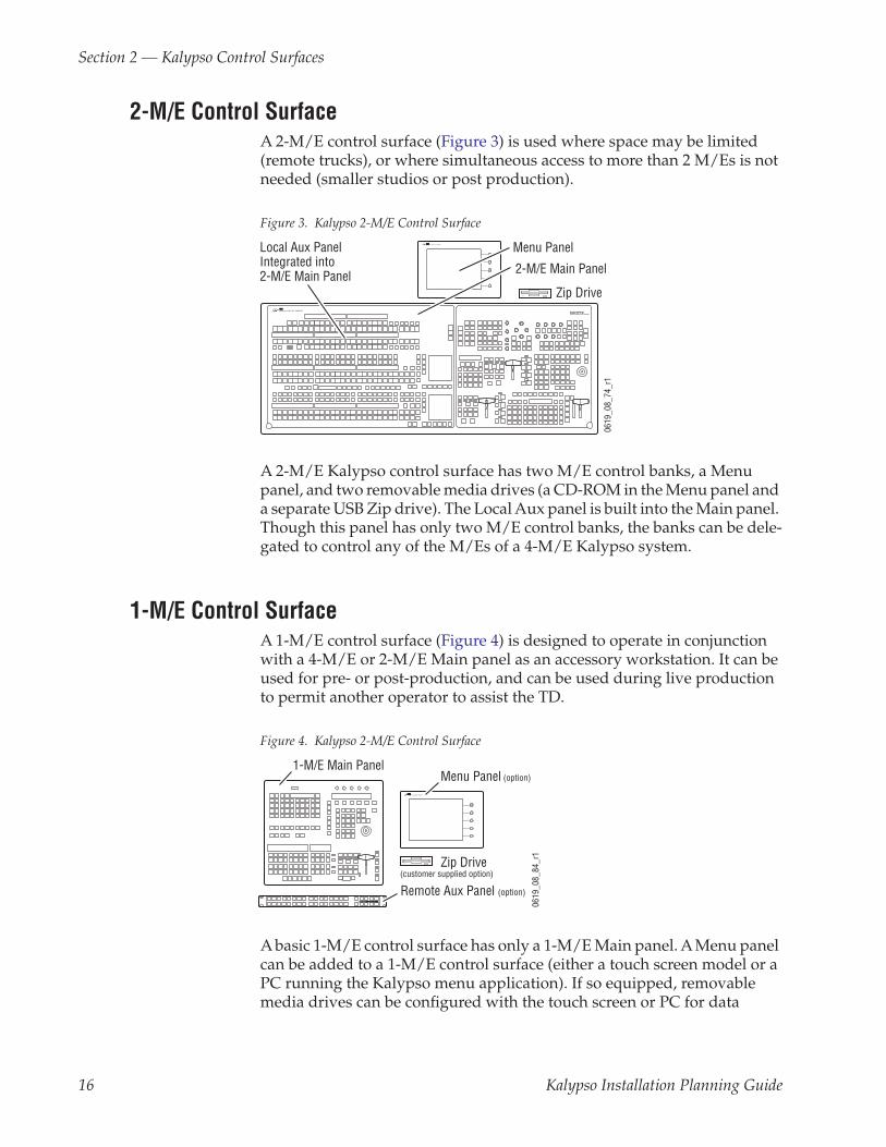
2-M/E Control SurfaceA 2-M/E control surface (Figure 3) is used where space may be limited (remote trucks), or where simultaneous access to more than 2 M/Es is not needed (smaller studios or post production).
Figure 3. Kalypso 2-M/E Control Surface
A 2-M/E Kalypso control surface has two M/E control banks, a Menu panel, and two removable media drives (a CD-ROM in the Menu panel and a separate USB Zip drive). The Local Aux panel is built into the Main panel. Though this panel has only two M/E control banks, the banks can be dele-gated to control any of the M/Es of a 4-M/E Kalypso system.
1-M/E Control SurfaceA 1-M/E control surface (Figure 4) is designed to operate in conjunction with a 4-M/E or 2-M/E Main panel as an accessory workstation. It can be used for pre- or post-production, and can be used during live production to permit another operator to assist the TD.
Figure 4. Kalypso 2-M/E Control Surface
A basic 1-M/E control surface has only a 1-M/E Main panel. A Menu panel can be added to a 1-M/E control surface (either a touch screen model or a PC running the Kalypso menu application). If so equipped, removable media drives can be configured with the touch screen or PC for data
0619
_08_
74_r
1
2-M/E Main Panel
Local Aux Panel Integrated into2-M/E Main Panel
Menu Panel
Zip Drive
0619
_08_
84_r
1
KALYPSO REMOTE AUX PANEL R E M O T E A U X P A N E L
1-M/E Main PanelMenu Panel (option)
Remote Aux Panel (option)
Zip Drive (customer supplied option)
16 Kalypso Installation Planning Guide

4-M/E and 2-M/E Main Panel Installation
storage. An optional Remote Aux panel can also be added for Aux bus con-trol. Though the 1-M/E Main panel has only one M/E control bank, it can be delegated to control any of the M/Es of a 2 or 4-M/E Kalypso system.
Removable Media DrivesTwo removable media drives are standard components of a Kalypso 4-M/E or 2-M/E system. Included are a CD-ROM drive (installed inside the Menu panel), and an external USB 250 MB Zip drive (which connects to the Menu panel). No special mounting brackets or specific placement is required for the Zip drive; placement is restricted only by USB cable length.
An external USB CD-ROM drive is provided with the Menu panel Flush Mount kit, as flush mount installation may block access to the drive inside the Menu panel. Other customer supplied USB drives can be added.
4-M/E and 2-M/E Main Panel Installation4-M/E and 2-M/E Main panel installations require careful attention to the console support structure and the console cutout dimensions necessary to accommodate the mounting flanges located on the front and sides of the tub (Figure 5).
Figure 5. Mounting Flanges
CAUTION The 4-M/E Main panel weighs approximately 86 kg (189 lb) and the 2-M/E Main panel weighs approximately 63 kg (138 lb). Prior to installation, ensure that your console is structurally capable of supporting the Main panel.
The 4 and 2-M/E Main panels are designed to be flush mounted in a con-sole, but it may also be surface mounted. Figure 6 provides installation details for both flush mount and surface mount installations. Refer to 4-M/E Main Panel on page 20 for dimensions and other information specific to the 4-M/E Main panel, or 2-M/E Main Panel on page 22 for information specific to the 2-M/E Main panel.
0619
_07_
52_r
0
SATELLITE PORTSTRANSMIT
RECEIVE
8 8 8 8 8 8 8 8
TRANSMITGP8
GP7
GP6
GP5
GENERALPURPOSELEDS
GP4
GP5
GP1
GP0
RECEIVE
SATELLITE PORTS
FAULT
INITRUN
XMT
C119
RCVLINK
RTP/CONTROL PANEL LANACTIVITY
COLN
C29
3.3V
R151R152
POWER SUPPLIESMENUPROCESSORRESET
R153
5V12V
SCSIHARD
DISK
56789012
34
TRUN
XMT
C119
RCVLINK
RTP/CONTROL PANEL LANACTIVITY
COLN
C29
3.3V
R151R152
POWER SUPPLIESMENUPROCESSORRESETR153
5V12V
SCSIHARD
DISK
0.43 in.11 mm
Kalypso Installation Planning Guide 17

Section 2 — Kalypso Control Surfaces
Figure 6. Main Panel Mounting Options, Front Left View
The Main panel lid is held in the open position by two gas spring assem-blies. The ability of these devices to support the lid is compromised if the installed panel tilts toward the user at an angle greater than 15 degrees.
Panel ventilation is accomplished by two fans which draw air through slots around buttons and expel it at the rear of the panel, where connections to the Kalypso Video Processor frame and other Control Surface components are located.
Cosmetic Bracket4-M/E and 2-M/E systems manufactured since March 2001 are shipped with a cosmetic bracket attached to the rear of the Main panel lid (Figure 7). The purpose of the cosmetic bracket is to cover a visible gap between the rear of the panel and the mounting surface when the panel is flush mounted. The cosmetic bracket is removable (see the Kalypso Installation and Service Manual for details) and can be ordered for older systems. It is recommended the bracket be removed if the Main panel is surface mounted.
Mounting Flange0.43 in. / 11 mm
0619
_04_
28_r
3
Panel Tub
Panel Lid
Surface Mount Flush MountConsole to tub Clearance
0.49 in. / 12 mm
Console.8125 in. / 21 mm
(typical)
Panel Tub
Panel Lid
Support Member Support Member
1.03 in. / 26 mm
Mounting Option
Cutout Dimensions
Aa
a Console surface cutout.
B1 Cb
b Distance between flush mount support members.
2-M/E 4-M/E 2-M/E 4-M/E 2-M/E 4-M/E
Flush Mountc, d
c Recommended tilt of 5˚; maximum tilt of 15˚. The recommended five degree tilt may be obtained by elevating the rear of the panelapproximately two inches relative to the front of the panel. d See Cosmetic Bracket (below) for additional flush mount considerations.
20.09 in. (510 mm)
25.06 in. (637 mm)
49.51 in. (1258 mm)
55.63 in. (1413 mm)
48.66in. (1236 mm)
54.78in. (1391 mm)
Surface Mount3 18.70 in. (475 mm)
23.81 in. (605 mm)
48.66in. (1236 mm)
54.78in. (1391 mm) n/a n/a
B
CA
18 Kalypso Installation Planning Guide

4-M/E and 2-M/E Main Panel Installation
Figure 7. Main Panel with Attached Cosmetic Bracket, Side View
If you choose to use the cosmetic bracket and your Main panel installation has a console support structure similar to that shown in Figure 8, it will be necessary to cut notches in the support members at the left and right rear corners of the console cutout (see the notch dimensions in Figure 8). This enables the Main panel lid to clear the support structure upon opening.
Figure 8. Support Member Notch Dimensions
0619
_05_
02_r
0
Cosmetic BracketMain Panel Lid
Main Panel Tub
.69 in..69 in.
17.53 mm17.53 mm
.27 in. / 6.86 mm.27 in. / 6.86 mm
00.60 in.00.60 in.
15.24 mm15.24 mm0.69 in.18 mm
0.27 in. / 7 mm
0.60 in.15 mm
0061
9_05
_05_
r2
AB
13 m
m / 0.5
in.
25 mm1.0 in.25 mm1.0 in.
ConsoleControl Panel Console Cutout
Notch
Support Member
Front
Back
Mounting Option
Dimensions
A Ba
a Console cutout dimension.
2-M/E 4-M/E 2-M/E 4-M/E
Flush Mount 19.09 in. (485 mm)
24.06 in. (611 mm)
20.09 in. (510 mm)
25.06 in. (637 mm)
Kalypso Installation Planning Guide 19

Section 2 — Kalypso Control Surfaces
4-M/E Main Panel4-M/E Main panel options include a redundant power supply and Source ID displays for M/E 1, 2, and 3. (Source ID displays are standard on PGM/PST and on the Local Aux panel.) Refer to Figure 9 through Figure 11 for panel dimensions and connector layout.
Figure 9. 4-M/E Main Panel Dimensions
Figure 10. 4-M/E Main Panel, Rear View
CAUTION Regardless of mounting method or cutout dimensions, ensure that there is at least 152 mm (6 in.) of clear space at the rear of the Main panel below the mounting surface for proper cable clearance and air flow. Allow an extra 203 mm (8 in.) to 254 mm (10 in.) of mounting surface behind the Main panel for peripheral components (e.g., Local Aux panel).
24.58 in.624 mm
(lid)
55.5 in. / 1410 mm (lid)
54.65 in. / 1388 mm (tub)
23.56 in.598 mm
(tub)
7.44 in.189 mm
(tub to topof lid)
0619
_00_
30_r
1Menu Panel
PowerLocal Aux Bus
PowerPanel
DiagnosticPanelLAN
Satellite ControlPanels (12)
NotUsed
AC In
8162
_00_
02_r
0
20 Kalypso Installation Planning Guide
4-M/E and 2-M/E Main Panel Installation
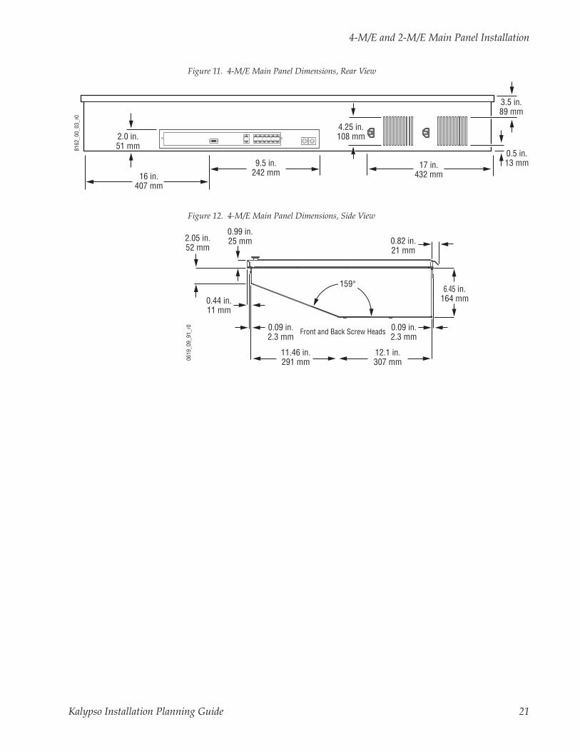
Figure 11. 4-M/E Main Panel Dimensions, Rear View
Figure 12. 4-M/E Main Panel Dimensions, Side View
8162
_00_
03_r
0
2.0 in.51 mm
16 in.407 mm
9.5 in.242 mm
17 in.432 mm
4.25 in.108 mm
0.5 in.13 mm
3.5 in.89 mm
6.45 in.164 mm
12.1 in.307 mm
11.46 in.291 mm
0.44 in.11 mm
2.05 in.52 mm
0.99 in.25 mm
0619
_09_
91_r
0
0.82 in.21 mm
0.09 in.2.3 mm
Front and Back Screw Heads0.09 in.2.3 mm
159°
Kalypso Installation Planning Guide 21

Section 2 — Kalypso Control Surfaces
2-M/E Main PanelSource ID displays are standard on the 2-M/E Main panel’s M/E 1 and PGM/PST buses and on the Local Aux subpanel. A redundant power supply is optional. Refer to Figure 13, Figure 14, and Figure 15.
Figure 13. 2-M/E Main Panel Dimensions
Figure 14. 2-M/E Main Panel, Rear View
CAUTION Regardless of mounting method or cutout dimensions, ensure that there is at least 152 mm (6 in.) of clear space at the rear of the Main panel below the mounting surface for proper cable clearance and air flow. Allow an extra 203 mm (8 in.) to 254 mm (10 in.) of mounting surface behind the Main panel for peripheral components.
19.0 in.483 mm
(lid)
49.31 in. / 1252 mm (lid)
48.54 in. / 1233 mm (tub)
18.45 in.469 mm
(tub)
8.13 in.207 mm
(tub to topof lid)
0619
_04_
50_r
4
8162
_00_
04_r
0
Aux Panel
Diagnostic EmergencyBypassMixer
EmergencyBypassRouter
Menu PanelPower
Local Aux BusPower
AC In
LAN RedundantDC Power In
PanelDiagnostic
PanelLAN
Satellite ControlPanels (12)
NotUsed
22 Kalypso Installation Planning Guide

4-M/E and 2-M/E Main Panel Installation
Figure 15. 2-M/E Rear Panel Dimensions
Figure 16. 2-M/E Main Panel Dimensions, Side View
8162
_00_
05_r
0
21 in.533 mm
20.5 in.527 mm
7.0 in.178 mm
1.0 in.25 mm
8.25 in.210 mm
9.5 in.242 mm
4.0 in.102 mm
18 in.457 mm
2.5 in.64 mm
0.5 in.13 mm
3.5 in.89 mm
4.25 in.108 mm
2.5 in.64 mm
13.54 in.344 mm
4.91 in.125 mm
2.22 in.56 mm
1.0 in.25 mm
0619
_09_
92_r
0 BackScrewHead
7.12 in.181 mm
0.09 in.2.3 mm
135°
0.82 in.21 mm
Kalypso Installation Planning Guide 23

Section 2 — Kalypso Control Surfaces
1-M/E Main Panel InstallationThe 1-M/E Main panel is designed for either flush or surface console mounting, or it can be installed in a standard 19 inch rack. The panel is ven-tilated with a fan that draws air through front vents and slots around the buttons and expels it out the recessed rear panel.
Figure 17. 1-M/E Main Panel Dimensions
Figure 18. 1-M/E Panel Mounting Options, Front Left View
3.99 in.101.3 mm
(to panel surface)
0619
_08_
85_r
1
15.73 in.399.5 mm
(lid)
18.02 in.457.7 mm
(lid)
19.0 in.482.6 mm
(lid & rack ears)
14.60 in.370.8 mm
(tub)16.96 in.430.8 mm
(tub)
0619
_08_
86_r
0
Panel TubPanel Surface
0.58 in. / 14.7 mm
Mounting Bracket
Panel Surface
Bracket1.02 in. / 26 mm
Panel Overhang0.53 in. / 13.5 mm
Routed Cutout0.53 in. / 13.5 mm
Routed Cutout0.41 in. 10.4 mm 0.40 in.
10.2 mm
Console .8125 in.21 mm(typical)
Panel Tub
Panel Surface
Mounting Bracket
Flush Mount Surface Mount
Mounting OptionConsole Cutout Dimensions
A B
Flush MountPanel surfacerouted cutout 15.98 in. (406 mm) 18.27 in (464 mm)
Panel tub cutout 14.85 in. (377 mm) 17.21 in. (437 mm)
Surface Mount 14.85 in. (377 mm) 17.21 in. (437mm) B
A
24 Kalypso Installation Planning Guide

1-M/E Main Panel Installation
Figure 19. 1-M/E Main Panel, Rear View
Figure 20. 1-M/E Rear Panel Dimensions
Figure 21. 1-M/E Rear Recess and Bottom Panel Dimensions
ACLINE 1
ACLINE 2
LAN SATELLITEPANEL
DIAGNOSTIC0 = NORMAL
RESET COM 1 COM 2
ACLINE 1
ACLINE 2 LAN SATELLITE
PANELDIAGNOSTIC0 = NORMAL
RESET COM 1 COM 2
0 1
5
23
4678
9COM 2Reset
ButtonBoot DialSwitch
LAN SatellitePanel
COM 1AC In
0619
_08_
88_r
1
Green LEDLink/Receive
Yellow LEDActivity
GroundLug
ACLINE 1
ACLINE 2
LAN SATELLITEPANEL
DIAGNOSTIC0 = NORMAL
RESET COM 1 COM 2
0619
_08_
89_r
114.44 in.366.8 mm
2.5 in.63.8 mm
0.58 in.14.8 mm
1.76 in.44.5 mm
0.76 in.19.4 mm
0.16 in.4.1 mm
1.48 in.38 mm
0.07 in.1.8 mm
6.24 in.158.5 mm
3.41 in.86.6 mm
Bracket at highest and lowest points.
0619
_08_
90_r
2
13.41 in.340.6 mm
4.12 in.104.6 mm
6.76 in.171.7 mm
7.84 in.199.1 mm
3.55 in.90.2 mm
Floppy ConnectorAccess Door
Exhaust Fan
Recessed Depth2.50 in.
63.5 mm
Kalypso Installation Planning Guide 25

Section 2 — Kalypso Control Surfaces
Local Aux Panel InstallationThe Local Aux panel (Figure 22) provides control of Kalypso System Aux buses, the Emergency Bypass system, Still Store source selection, switched preview, gang roll control, and router source selection. The Local Aux Panel is integrated into the design of the 2-M/E Main panel, so a separate Local Aux panel is not provided with 2-M/E systems.
Figure 22. Local Aux Panel Dimensions
Ports located on the rear of the Local Aux panel (Figure 23) provide connec-tions to the Kalypso Main panel. The Kalypso system may also be config-ured with several types of Remote Aux panel. Refer to Remote Aux Panels on page 37 for more information on these panels.
Figure 23. Local Aux Panel Connections
Bypass Active
Assign
EmergencyBypass
Select Source
Key2
Key1
BypassDelegate
Aux1
Aux2
Aux3
Aux4
Aux8
Aux5
Aux6
Aux7
Aux9
Aux10
Aux11
Aux12
M / E1
PGMPST Near
SideUnShift
KeySplit
ShiftHoldM / E2
M / E3
PrevPage
GangSelect
RouterAssignNext
PageAux1
Aux2
Aux3
Aux4
Aux5
Aux11
Aux12
StillStore
M / E1
M / E2
M / E3
PGMPST Hold Near
SideUnShift
KeySplit
Shift FarSide
BypassEnable
Aux13
StillStore
PVWPri
Aux6
Aux7
Aux8
Aux13
PVWPri
Aux9
Aux10
26.3 in.668 mm
7.2 in.183 mm
0619
_00_
10_r
6
1.8 in.46 mm
1.8 in.46 mm
3.9 in.99 mm
8.4 in.213 mm
BottomView
SideView
WithoutMountingBracket
Spare EmergencyBypassMixerDiagnostic
EmergencyBypassRouter
LAN
0618
_03_
127_
r2
Main and Redundant DC Power In
Local Aux PanelBoot Dial
(recessed)
Local Aux PanelReset Button
26 Kalypso Installation Planning Guide

Local Aux Panel Installation
Mounting BracketsWhen ordering your Kalypso system, you will specify the type of Local Aux panel mounting bracket (flush or console). If a preference is not given, flush mount brackets will be shipped. Flush mount brackets depicted in Figure 24 provide console flush mount capability.
Figure 24. Local Aux Panel Console Flush Mount
When flush mounting the Local Aux panel, leave the area near the fan open for cooling (Figure 25).
Figure 25. Local Aux Panel Fan Position
0619
_00_
23_r
2
.875 in.22 mm
Flush Mount Brackets
Aux Panel (bottom view)Console
Aux Panel Console Cutout Dimensions
A B
7.32 in. (186 mm) 26.42 in. (671 mm)
A
B
0.75 in.19 mm
3.0 in.76 mm
3.0 in.76 mm
Aux PanelRear View
3.0 in.76 mm
3.5 in.89 mm
0619
_04_
72_r
1
Kalypso Installation Planning Guide 27

Section 2 — Kalypso Control Surfaces
Figure 26 provides guidance for mounting the Local Aux panel using free-standing console brackets so that its Source Selection buttons align with those on the 4-M/E Main panel.
Figure 26. Recommended Bracket Placement for Console Mounting Local Aux Panel
Power Cabling
4-M/E SystemsNormally, the Local Aux panel receives power from the Main panel via a cable connected between the two panels. If the Main panel has two power supplies, there is already redundant power protection. It is also possible to install an external power supply (see Figure 27) for additional redundancy that connects to the Redundant DC Power In connector on the Local Aux panel (see Figure 23). If desired, two separate external power supplies can be connected to the Local Aux panel. This eliminates the need to connect a power cable from the Main panel to the Local Aux panel.
2-M/E SystemsLocal Aux control is integrated into the 2-M/E Main panel, but it has a sep-arate processor. It is powered by a direct connection inside the Main panel. If the Main panel has two power supplies, there is already Local Aux
0619
_00_
46_r
0
3.91 in.99 mm
Measurementsreferenced to leftrear corner of tub.
Main Panel
4.68 in.119 mm
2.5 in.64 mm
2.0 in.51 mm
1.05 in.27 mm
3.0 in.76 mm
22.73 in.577 mm
Local Aux PanelConsole Bracket Footprint
Grass V Grass Valley alley Group Group
Kalypso Kalypso
0619
_00_
45_r
1
Local Aux Panel
Fixed FreestandingConsole Brackets
Console
Main Panel
28 Kalypso Installation Planning Guide
Menu Panel Installation
control redundant power protection. You can optionally add an external power supply (see Figure 27) that connects to the Aux Panel Redundant DC Power In connector on the Main panel (see Figure 14).
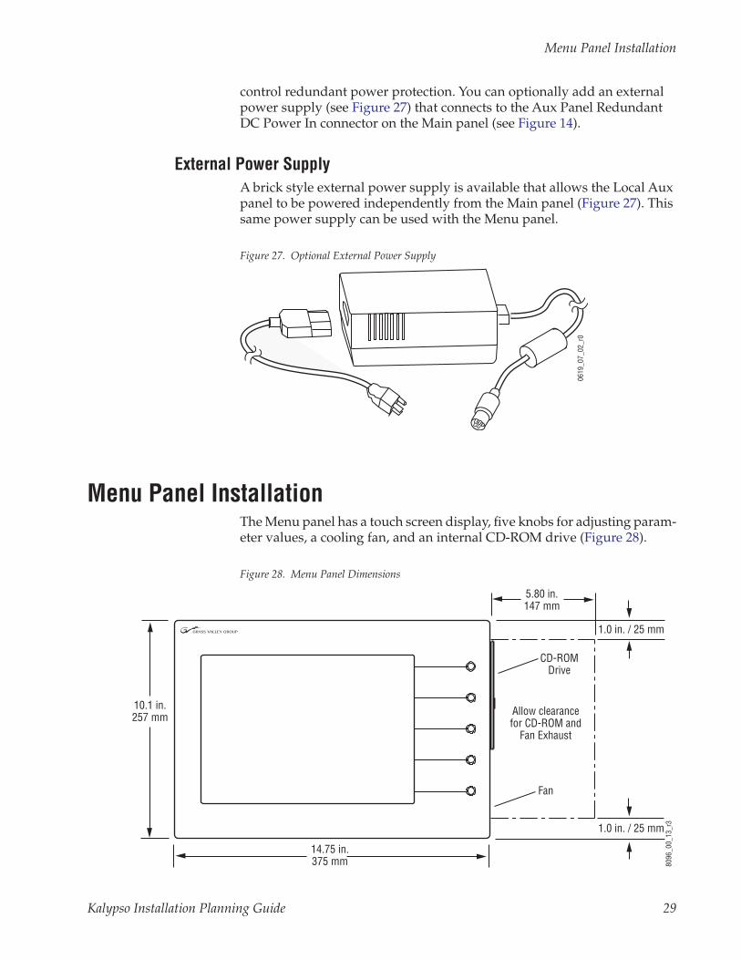
External Power SupplyA brick style external power supply is available that allows the Local Aux panel to be powered independently from the Main panel (Figure 27). This same power supply can be used with the Menu panel.
Figure 27. Optional External Power Supply
Menu Panel InstallationThe Menu panel has a touch screen display, five knobs for adjusting param-eter values, a cooling fan, and an internal CD-ROM drive (Figure 28).
Figure 28. Menu Panel Dimensions06
19_0
7_02
_r0
8096
_00_
13_r
3
14.75 in.375 mm
10.1 in.257 mm
5.80 in.147 mm
Allow clearancefor CD-ROM and
Fan Exhaust
1.0 in. / 25 mm
Fan
1.0 in. / 25 mm
CD-ROMDrive
Kalypso Installation Planning Guide 29

Section 2 — Kalypso Control Surfaces
Ports located on the rear of the Menu panel (Figure 29) provide connections to the Main panel, Video Processor frame, an external USB Zip drive, a PS/2 mouse and keyboard, and other devices. For example, the USB ports can be used with a USB style mouse and keyboard, and/or for additional USB data storage devices.
Figure 29. Menu Panel, Bottom and Side Views
Menu Panel VentilationAir is drawn into the Menu panel through slots along the top and left side of the panel. Air is expelled out of the Menu panel by a fan located on the right side of the panel (see Figure 28). When mounting the panel, be sure to leave either the top or left side slots unobstructed for proper air intake. The right side of the panel requires clearance for the fan exhaust.
Recommended Mounting LocationThe recommended mounting location for the Menu panel is to the left or right of the Main panel (see Figure 30). This provides the most comfortable reach to the touch screen, soft knobs, and internal CD-ROM and also clears
8096
_00_
14_r
5
2.5 in.64 mm
Left SideView
Panel Bottom
Rear of panel
Alternative Four Hole Pattern forAdjustable Freestanding Console Bracketor Articulated Arm
Serial Ports
1.6 in.41 mm
4.3 in.109 mm
**
*
*◊
= Hole pairs (top and bottom) for Flush Mount kit◊= Hole pair for Adaptable Mounting Bracket (5)*
USB Ports PS/2 Mouse/Keyboard Ethernet Power
LAN DC INMOUSE KEYBOARDUSB 1
USB 2RESET
COM 3 CROSSOVER
COM 4
Link LED
30 Kalypso Installation Planning Guide

Menu Panel Installation
the area for better viewing of monitors beyond the Main panel. When con-sidering mounting options, remember that the optimum Menu panel viewing angle is 90 degrees in both the horizontal and vertical planes.
Figure 30. Recommended Menu Panel Mounting Location
CAUTION When finalizing the location of the Menu panel, be sure to open the Main panel lid and check for sufficient clearance between the Menu panel and the Main panel components.
Available Mounting BracketsWhen ordering your system, you will specify the type of Menu panel mounting bracket. Three different mounting brackets are available to provide a wide variety of installation options. One bracket type is included with each system, and one additional bracket of your choice is also included:
• Adaptable Mounting bracket (always included), and choose either
• Adjustable Freestanding Console bracket,
- or -
• Flush Mount kit.
If a preference is not given, the Flush Mount kit will be shipped.
CAUTION All Menu panel mounting holes are tapped 10-32. Do not penetrate the case more than 0.24 in. / 6.10 mm.
Bypass Active
Assign
EmergencyBypass
Select Source
BypassEnable Key
OnSource 2
KeyOn
Source 1Bypass
DelegateAux
1 Aux2 Aux
3 Aux4
Aux8
Aux5 Aux
6 Aux7 Aux
9 Aux10 Aux
11 Aux12 PVW
StillStore
1Still
Store2
M / E1 PGM
PST
NearSide
UnShift Key
Split
ShiftHold
M / E2 M / E
3
PrevPage
GangSelect
RouterAssign
NextPage
Aux1 Aux
2 Aux3 Aux
4 Aux5 Aux
6Aux
7Aux
8Aux
9Aux
10Aux
11 Aux12 Still
Store1
StillStore
2PVW M / E
1 M / E2 M / E
3 PGMPST Hold
NearSide
UnShift Key
Split
ShiftFar
Side
Menu Panel
Adjustable Freestanding Console Bracket
Local Aux Panel
Main Panel
8162
_00_
06_r
1
Console
Kalypso Installation Planning Guide 31

Section 2 — Kalypso Control Surfaces
Adaptable Mounting BracketThe Adaptable Mounting bracket allows the Menu panel to be mounted from above, from below, or from the back, using pairs of screw holes as shown in Figure 31.
Figure 31. Optional Placement of Adaptable Mounting Bracket
This Adaptable Mounting bracket allows the Menu panel to be tilted on a horizontal axis for optimum viewing. After the final location and angle of the Menu panel has been established, tighten the clamping pivot screws. This bracket is not intended to be friction-lock adjustable.
2.06 in.52 mm
10.36 in.263 mm
BottomMounts
6.57 in.167 mm
2 x 0.25 in. / 6.35 mm diameter
Bottom
LeftSide
RightSide
MountingBracket
4.20 in.107 mm
3.96 in.101 mm
1.00 in. / 25 mm
Upper back
Lower back
CD-ROM Drawer
TopMount
MountingBracket
Hole Sizesand Spacing
8096
_00_
15_r
0
Exhaust Fan
32 Kalypso Installation Planning Guide

Menu Panel Installation
Adjustable Freestanding Console BracketA single four-hole screw pattern on the back of the Menu panel (Figure 29) accommodates the Adjustable Freestanding Console bracket. This bracket’s friction-lock can be set during installation to allow the user to tilt the Menu panel on a horizontal axis during use for optimum viewing.
The Adjustable Freestanding Console bracket can be used to mount the Menu panel to the console in the recommended position (Figure 30 on page 31). The Menu panel can also be mounted above the Main panel with this bracket, as shown in Figure 32. If installed in this orientation, follow the recommended mounting dimensions to ensure adequate clearance when the Main panel lid is opened.
Figure 32. Optional Placement of Menu Panel
CAUTION When finalizing the location of the Menu panel, be sure to open the Main panel lid and check for sufficient clearance between the Menu panel and the Main panel components. Without sufficient clearance, the lever arm or joy-stick could damage the Touch Screen when the Main panel is opened.
If an overhang or wall exists by the Main panel, this bracket can be rotated to mount the Menu panel to that surface (like the Adaptable Mounting bracket). The four-hole screw pattern on the Menu panel may also be used to attach a user-supplied articulated arm, for even more flexibility.
0619
_00_
00_r
2
3.91 in.99 mm
Measurementsreferenced to leftrear corner of tub.
Main Panel
4.68 in.119 mm
2.5 in.64 mm
7.0 in.178 mm
(minimum)
2.5 in.64 mm
2.0 in.51 mm
1.05 in.27 mm
3.0 in.76 mm
10.0 in.254 mm
22.73 in.577 mm 8.86 in.
225 mm6.0 in.
152 mm
Local Aux PanelConsole Bracket Footprint
Menu PanelConsole Bracket Footprint
Grass V Grass Valley alley Group Group
Kalypso Kalypso
0619
_00_
44_r
10
Local Aux PanelFixed FreestandingConsole Brackets
Menu Panel
Adjustable FreestandingConsole BracketConsole
Main Panel
Kalypso Installation Planning Guide 33

Section 2 — Kalypso Control Surfaces
Flush Mount KitThe Flush Mount kit allows the Menu panel to be installed in a standard 19 in. (483 mm) rack (Figure 33), occupying seven rack units. Alternatively, the Menu panel can be set into a console cutout (Figure 35 on page 36).
Access to the CD-ROM on the right side of the Menu panel is blocked with this mounting option, so an external CD-ROM with a USB cable is pro-vided. The external CD-ROM drive connects to one of the two USB ports on the Menu panel, and receives its power through this cable.
Clearance for the exhaust fan on the right side of the panel and the inter-connect cables to the external CD-ROM, Main panel and Video Processor frame on the bottom of the panel must also be taken into consideration when mounting the panel in this manner.
Figure 33. Optional Flush Mount Kit
8096
_03_
03_r
1
Flush Mount BezelMenu Panel
19 in.483 mm
12.22 in.310 mm
34 Kalypso Installation Planning Guide

Menu Panel Installation
The Flush Mount bezel is attached to the top and bottom of the Menu panel with two mounting brackets as shown in Figure 34. Four #10 screws are included for attaching the Flush Mount assembly to the Menu panel.
Figure 34. Attaching Flush Mount Bezel to Menu Panel
To install the Menu panel into a console cutout, the Flush Mount bezel is removed. The mounting brackets directly support the top and bottom of the Menu panel. Eight wood screws (not provided) are required for securing the mounting brackets to the console. The Menu panel attaches to the bracket using slotted holes, permitting a 1.5 in. (38 mm) range of height adjustment to accommodate different console thicknesses (Figure 35 on page 36). For the best cosmetics, it is recommended to have the Main panel protrude slightly above the console surface to conceal the cut console edge.
CAUTION Console thickness should not be less than 0.5 in./13 mm for proper support of the Menu panel.
Dimensions for the console cutout without the Flush Mount bezel are given in Figure 36 on page 36.
Mounting Brackets
x2
x2x4
Top
Bottom
RightSide
Exhaust Fan
CD-ROMDrive(not used)
8096
_03_
04_r
2
Menu Panel CablingIncluding External
CD-ROM
x4
Kalypso Installation Planning Guide 35

Section 2 — Kalypso Control Surfaces
Figure 35. Menu Panel Console Installation
Figure 36. Menu Panel Console Cutout Dimensions
Power CablingThe Menu panel normally receives its power from the Main panel. The Menu panel can be powered separately using the same model optional power supply available for the Local Aux panel (see Figure 27 on page 29).
Bottom
RightSide
x2
Top
x4
x2x4
8218
_00_
07_r
0
Console thickness:1.25 in./32 mm (maximum)0.5 in./13 mm (minimum)
Exhaust Fan
Menu Panel CablingIncluding External
CD-ROM
CD-ROM(not used)
Mounting Brackets
10.31 in. 262 mm
If console thickness exceeds 1.25 in. / 32 mm, route these areas from far side.
14.81 in. / 376 mm
4x R 0.0625 in. / 1.5 mm permitted
2x 0.85 in. 22 mm
8096
_03_
02_r
1
36 Kalypso Installation Planning Guide

Optional System Components
Optional System Components
Remote Aux PanelsRemote Aux panels control Kalypso aux buses from remote locations. Three 24-Crosspoint and two 32-Crosspoint Remote Aux panel configura-tions are available for Kalypso systems. Refer to Table 7 and the following sections for panel-specific information.
Remote aux panels may be purchased with the Kalypso system or added at a later time. For more information on Kalypso options, refer to the Kalypso Ordering Guide or the Grass Valley Group Full Line Product Catalog. Online documentation is available on the Grass Valley Group web site. The URL for the Grass Valley Group web site is found on the copyright page at the front of this manual.
Note Remote Aux panels used with Model 2200, 3000, and 4000 systems can be upgraded to 24-Crosspoint functionality for use in a Kalypso environment. See the Kalypso Model 4000 Remote Aux Panel Upgrade Instruction Manual for details.
24-Crosspoint Remote Aux PanelsThese panels are designed to select 48 external sources (24 unshifted and 24 shifted). Up to Thirty-two 24-Crosspoint Remote Aux panels can be daisy-chained on a single serial control port on a Kalypso Video Processor frame. Three panel configurations are available, identified by the number of rack units (RUs) each occupies in a standard 19 in. (483 mm) equipment rack (see Figure 37 through Figure 39). The 1 and 2 RU panels (KAL-24AUX1 and KAL-24AUX2) are dedicated to a single bus. The 3 RU panel (KAL-24AUX3) panel has 18 bus delegate buttons. All three panels have the same connectors and DIP switches as that depicted for the KAL-24AUX1 in Figure 40 on page 38.
Table 7. Remote Aux Panel Summary
24-Crosspoint Aux Panel 32-Crosspoint Aux Panel
Connection Serial Port Daisy Chain Ethernet
Maximum Panelsa
a A maximum of 40 Remote Aux panels, in any combination, can be connected to a 4-M/E or 2-M/E.
32 40
External Sources Controlled 48 (24 unshifted, 24 shifted) 64 (32 unshifted, 32 shifted)
Available Configurations
KAL-24AUX1 (1 RU, single bus) KAL-32AUX1 (single bus)
KAL-24AUX2 (2 RU, single bus) KAL-32AUX2 (16 bus delegate buttons)
KAL-24AUX3 (3 RU, 18 bus delegate buttons) --
Kalypso Installation Planning Guide 37

Section 2 — Kalypso Control Surfaces
Figure 37. KAL-24AUX1 (1 RU)
Figure 38. KAL-24AUX2 (2 RU)
Figure 39. KAL-24AUX3 (3 RU)
24-Crosspoint Remote Aux ConnectionsThe 24-Crosspoint Remote Aux rear panels have connectors for DC power, Communications Bus, and Joystick Override (Figure 40).
Figure 40. KAL-24AUX1 (1 RU), Rear View
Note All KAL-24AUX rear panels have similar layouts and have the same connec-tors.
REMOTE AUX PANEL
11 2 3 4 5 6 7 8 9 1010 1111 1212 1313 1414 1515 1616 ONONAIRAIR1 2 3
PgmPgmPstPst
M/EM/E M/EM/E M/EM/E1717 1818 1919 2020 2121 2222 2323 2424 Shi f tShi f t
0619
_04_
64_r
1
REMOTE AUX PANELREMOTE AUX PANEL
10109876542 31
242423232222
1111
21212020191918181717
1616151513131212 1414
PstPstPgmPgm
3M/EM/E
2M/EM/E
1M/EM/EShiftShift
0619
_04_
67_r
1
REMOTE AUX PANELREMOTE AUX PANEL
10109876542 31
242423232222
1111
21212020191918181717
1616151513131212 1414
PstPstPgmPgm
3M/EM/E
2M/EM/E
1M/EM/EShiftShift
3A3AAuxAux
2A2AAuxAux
1A1AAuxAux
9A9AAuxAuxAuxAux
8A8AAuxAux7A7A6A6A
AuxAux5A5AAuxAux
4A4AAuxAux
AuxAux4B4B
AuxAux5B5B3B3B
AuxAux2B2BAuxAux
1B1BAuxAux AuxAux
9B9B7B7BAuxAux
8B8BAuxAuxAuxAux
6B6B
0619
_04_
69_r
1
-
+
COMMUNICATIONSBUS
SHIELD
DC POWER
JOYSTICK OVERRIDE
6432168421 8421
FORCE HIGH TALLY
MODETEST
ADDRESSPANEL
OFF
ON
0619
_04_
65_r
0
DC PowerTest Mode Panel Address and
Force High TallyJoystick OverrideCommunications Bus
38 Kalypso Installation Planning Guide

Optional System Components
Power Supply – The 24-Crosspoint Remote Aux panel power supply (Figure 41) should be securely fastened to a horizontal surface or attached to a support inside the equipment rack. Verify that the power supply cord reaches the 24-Crosspoint Remote Aux Control panel and the AC source.
Figure 41. KAL-24AUX Power Supply
Communications Bus – The communications bus cable connector shipped with each panel must be attached to the supplied cable or a user fabricated cable (refer to Figure 42). The supplied cable is 50 m (164 ft) long and has a pre-wired 9-pin D connector on one end.
If fabricating a cable, use a shielded twisted pair cable such as Belden 8451 and refer to Table 8 for wiring connections. The total length of cable in a 24-Crosspoint Remote Aux panel daisy-chain cannot exceed 320 m (1000 ft). Allow enough cable to reach each control panel connector, plus about 1 m (approximately 3 ft) extra.
Figure 42. KAL-24 AUX Communications Bus Connector Cable Wiring
Table 8. Cable Polarity
Panel Connector
D-Connector Pins
Factory Supplied Cable
+ (Plus) 3 and 7 Red
- (Minus) 2 and 8 Black
Shield 9 Shield
0619
_04_
63_r
1
0619
_04_
66_r
0
To Pin 9 ofD Connector(SHIELD)
To Pins 2 and 8 ofD Connector (–)
To Pins 3 and 7 ofD Connector (+)
To Next Panel(If Any)
Side View Connector-endView
From Switcher orPrevious Panel
Kalypso Installation Planning Guide 39

Section 2 — Kalypso Control Surfaces
Joystick Override – A user fabricated cable, external switch, and a 9-pin D con-nector are required to implement camera joystick override. Use shielded cable and connect the shield to the metal connector shell when fabricating the joystick override cable. Refer to Figure 43 for connector wiring.
Figure 43. KAL-24AUX Joystick Override Connector Cable Wiring
32-Crosspoint Remote Aux PanelsThese panels are designed to select 64 external sources (32 unshifted and 32 shifted). Up to forty 32-Crosspoint Remote Aux panels can be network con-nected to a Kalypso Video Processor frame. Two panel configurations are available, identified by the number of rack units (RUs) each occupies in the standard 19 in. (483 mm) equipment rack (see Figure 44 and Figure 45). Both panels have the same connector layout as that depicted for the KAL-32AUX1 in Figure 46.
The 1 RU panel (KAL-32AUX1) is dedicated to a single bus. The 2 RU panel (KAL-32AUX2) panel has 16 bus delegate buttons, that can be any of up to 16 Aux buses in the switcher.
Figure 44. KAL-32AUX1 (1 RU)
Figure 45. KAL-32AUX2 (2 RU)
Momentary Contact Switches
0619
_04_
71_r
5
Pin 1
Pin 9Pin 6
Pin 5
Common
1
2
3
4
6
7
8
5
9
D-9 MaleJoystick Override
Connector(wiring side)
KALYPSO REMOTE AUX PANEL
1 2 3 4 5 6 7 8 9 10 11 12 13 14 15 16 M/E1
M/E2
M/E3
PgmPst
Hold
17 18 19 20 21 22 23 24 25 26 27 28 29 30 31 32 Un-Shift
Shift KeySplit
NearSide
FarSide
0619
_04_
58_r
3 R E M O T E A U X P A N E L
KALYPSO REMOTE AUX PANEL
1 2 3 4 5 6 7 8 9 10 11 12 13 14 15 16 M/E1
M/E2
M/E3
PgmPst
Hold
17 18 19 20 21 22 23 24 25 26 27 28 29 30 31 32 Un-Shift
Shift KeySplit
NearSide
FarSide
AUX1
AUX2
AUX3
AUX4
AUX5
AUX6
AUX7
AUX8
AUX9
AUX10
AUX11
AUX12
AUX13
AUX14
AUX15
AUX16
0619
_04_
60_r
3
R E M O T E A U X P A N E L
Display Area
40 Kalypso Installation Planning Guide

Optional System Components
32-Crosspoint Remote Aux ConnectionsThe 32-Crosspoint Remote Aux rear panels have connectors for AC power, LAN, and Camera Joystick Override (Figure 46).
Figure 46. KAL-32AUX1 (1 RU), Rear View
Note The rear panel layout is the same for both KAL-32AUX panels.
AC Power – The 32-Crosspoint Remote Aux panels have internal power sup-plies which connect directly to facility AC power by supplied line cords.
LAN – The 32-Crosspoint Remote Aux panels employ Ethernet network con-figuration. Refer to Ethernet Switches and Hubs on page 57 for information on system topography.
Camera Joystick Override – A user fabricated cable, external switch, and a 15-pin D connector are required to implement camera joystick override. Use shielded cable and connect the shield to the metal connector shell when fabricating the joystick override cable. Refer to Figure 47 for connector wiring.
Figure 47. KAL-32AUX Joystick Override Connector Cable Wiring
RATED CURRENT: 0.35 ACAMERA JOYSTICK
OVERRIDEFREQUENCY: 47-440 Hz
RATED VOLTAGE RANGE: 85-260 VAC
LAN
0619
_04_
59_r
2
LANCamera Joystick OverrideAC Power
Common
0619
_04_
62_r
3
1
2
3
4
6
7
8
5
9
10
11
12
13
15
14
Pin 1
Pin 15Pin 9
D-15 MaleJoystick Override
Connector(wiring side)
Pin 8
Momentary Contact Switches
Kalypso Installation Planning Guide 41

Section 2 — Kalypso Control Surfaces
Shot BoxThe E-MEM Shot Box (Figure 48) is a separate panel that is designed for rapidly recalling previously built effects. Features include single button delegation for M/E 1, 2, 3, or PGM/PST, five pages of 20 registers allowing access to all 100 registers, register and page readout display, and Pvw, Run and Auto Run controls.
The Shot Box operates with Release 5.0 and higher software versions using the Editor protocol.
Figure 48. Kalypso Shot Box
InstallationThe dimensions in Figure 49 allow clearance for sheet metal and fasteners, and provide top plate overlap of approximately 0.6 in. (15 mm) on all sides. If the mounting surface is 0.75 in (19 mm) or less in thickness, the mounting nuts will not need to be countersunk (Figure 49). Refer to Figure 50 for exact screw placement and sheet metal dimensions.
SHOT BOX
M/M/E 1 M/M/E 2 M/M/E 3 P/P/P
Misc 1Misc 1 Misc 2Misc 2 Misc 3Misc 3 Misc 4Misc 4
Misc 5Misc 5 Misc 6Misc 6 Misc 7Misc 7 DPMDPM
SS ASS A SS BSS B SS CSS C AllAll
M/EM/E
1
PagePage AutoAutoRunRun
RunRun
0 1 2 3
8 9 1010 1111
1616
4 5 6 7
1313 1414 15151212
1717 1818 1919
M/EM/E
2M/EM/E
3
0721
_07_
65_r
1
42 Kalypso Installation Planning Guide

Optional System Components
Figure 49. Shot Box Cutout
Figure 50. Shot Box Dimensions
0721
_07_
66_r
2
7.3 in
186 mm
5.75 in147 mm
8.5 in
216 mm 6.75 in172 mm
0.75 in19 mm
Top View
8.5 in.216 mm
0.25 in.6 mm
4.0 in.102 mm
1.38 in.35 mm
1.63 in.41 mm
5.25 in.133 mm
8.0 in.203 mm
0.7 in.18 mm
6.75 in.172 mm
2.3 in.57 mm 2.0 in.
51 mm1.08 in.27 mm
0721
_07_
67_r
1
Rear View
Kalypso Installation Planning Guide 43

Section 2 — Kalypso Control Surfaces
CablingThe provided cables connect the Main panel, Shot Box, and Video Pro-cessor frame as shown in Figure 51. Power passes from the Main panel to the Shot Box over this cable.
Figure 51. Provided Shot Box Cables and Connections
Optional Satellite Panel ExtensionIf the Shot Box is to be placed more than 3 m (10 ft) from the Main panel, an optional Satellite Panel extension kit is available, permitting installation up to 100 meters away. The kit consists of a Y-cable (to separate the communi-cation path from the power path), a separate power supply, and two adapters. A Cat-5 extension cable of the desired length is to be provided by the end user. The Satellite Panel extension kit cabling replaces any existing Shot Box cabling (Figure 52).
Figure 52. Shot Box Panel Extension Cabling, Editor Port Connection
Male
To Video ProcessorFrame Editor Port
16 m (52 ft)
To Shot Box
To Main PanelSatellite Port
3 m (10 ft)
0619
_05_
07_r
2
0.3 m (1 ft) Female Male
To Video ProcessorFrame Editor Port
User Supplied Cat-5 Cable100 meter maximum length
8159
_00_
01_r
1
To Shot Box
Option KitY-Cable
PlugJ2
9-Pin to RJ-45Adapter
RJ-45Barrel
Adapter
PowerSupply
To ACSource
44 Kalypso Installation Planning Guide

Pinouts
Pinouts
4- and 2-M/E Main Control Panel
1-M/E Main Control Panel
Table 9. Console Ports
Console Ports Pin Panel Diagnostic
1 DSD
2 RXD
3 TXD
4 DTR
5 Chassis Ground
6 DSR
7 RTS
8 CTS
9 Reserved
Table 10. 1-ME Console Ports
Console Ports Pin Main Panel Proc. Com 1 Main Panel Proc. Com 2
1 DSD DSD
2 TXD TXD
3 RXD RXD
4 DSR DSR
5 Chassis Ground Chassis Ground
6 DTR DTR
7 CTS CTS
8 RTS RTS
9 Reserved (low) Reserved (high)
Pin 1
Pin 9
Pin 6
D-9 Male
Pin 5
Pin 5
Pin 6
Pin 9
D-9 Female
Pin 1
Kalypso Installation Planning Guide 45

Section 2 — Kalypso Control Surfaces
Menu Panel Table 11. Menu Panel Serial Ports
Serial PortsRS-232 Pin Menu Proc.
COM 3Menu Proc.
COM 4
1 DSD DSD
2 RXD RXD
3 TXD TXD
4 DTR DTR
5 Chassis GND Chassis GND
6 DSR DSR
7 RTS RTS
8 CTS CTS
9 Menu Reseta
a Open circuit or Mark (-5 to -15 volts) is run. Space (+5 to +15 volts) is reset.
RI (Ring Indicator)
Pin 1
Pin 9
Pin 6
D-9 Male
Pin 5
46 Kalypso Installation Planning Guide

Section 3Kalypso Classic Frame
Kalypso Classic Video Processor FrameThe Kalypso Classic Video Processor frame is a 13 rack unit chassis which mounts in a standard 483 mm (19 in.) rack (Figure 53 on page 48). An addi-tional 2 rack unit power supply is also required (Figure 56 on page 51).
The Video Processor frame has a built-in cooling system consisting of a fan/plenum mounted in the upper section of the frame, and an air filter in the lower section. Cooling air is drawn in at the lower sides of the frame, up through the filter and modules, then expelled out the back of the fan/plenum. In racks with forced air cooling that enters from above, heated exhaust air may be forced down to the air intakes and cause elevated frame temperatures. In these cases installing ducts or baffles to keep airflows sep-arate is advised.
Kalypso Installation Planning Guide 47

Section 3 — Kalypso Classic Frame
Figure 53. SD Video Processor Frame Dimensions
The Kalypso Classic Video Processor frame has front and rear bays. The front bay (Figure 54) provides access to the Fan Drawer, Air Filter, and removable modules such as the Control, Crosspoint, M/E, and Sync Gen-erator.
CAUTION For clarity, the Kalypso Classic Video Processor frame is shown below with the front door removed. The front door must remain in place and closed during normal system operation to maintain maximum cooling efficiency.
17 in.432 mm
Air Exhaust
22.75 in.578 mm
22.125 in.562 mm
AirIntake
19 in.483 mm
0619
_00_
03_r
5
Air Intake(both sides)
0.93 in.24 mm
48 Kalypso Installation Planning Guide

Kalypso Classic Video Processor Frame
Figure 54. SD Video Processor Frame, Front Bay View
DC POWER
0619
_00_
02_r
9
ON
OFF
Fan Drawer
Power Switch
Slot A1ControlModule
Slot A5Still Store
Module (optional)
Air Filter Slot A11 - A14M/E Modules
(PGM/PST, M/E 1, 2, 3)
Slot A15 - A16Transform Engine
Modules (2, optional)
Slot A17Sync Generator
Module
Slots A8 - A10Crosspoint
Modules (3)
Kalypso Installation Planning Guide 49

Section 3 — Kalypso Classic Frame
Power, control, and video connections are made at the rear of the Video Processor frame. Figure 55 shows a fully loaded rear bay. Some of the front and rear bay modules shown in Figure 54 and Figure 55 are optional and may not be included in your system configuration.
Figure 55. SD Video Processor Frame, Rear Bay View
J4
J3TIMECODE IN
J2
J1
REFERENCE
REFERENCEIN
OUTINJ6
J4
J5
J8J7
J10J92 1
J13J125 4
J16J158
J113
J146 7
422/CPL
SERIALPORTS
GPI
COMM 1
COMM I/O
CONTROLPANEL
LANJ1
FACILITYLAN
J2
STILLSTORE
LANJ3
SERIALOUTPUT
J1
J2
J3
J4
J5
J6
J7
J8
J9
J10
J11
J12
J13
J14
J15
J16
SERIALOUTPUT
J1
J2
J3
J4
J5
J6
J7
J8
J9
J10
J11
J12
J13
J14
J15
J16
SERIALOUTPUT
J1
J2
J3
J4
J5
J6
J7
J8
J9
J10
J11
J12
J13
J14
J15
J16
SERIALOUTPUT
J1
J2
J3
J4
J5
J6
J7
J8
J9
J10
J11
J12
J13
J14
J15
J16
SERIALOUTPUT
J1
J2
J3
J4
J5
J6
J7
J8
J9
J10
J11
J12
J13
J14
J15
J16
SERIALINPUT
J1
J2
J3
J4
J5
J6
J7
J8
J9
J10
J11
J12
J13
J14
J15
J16
SERIALINPUT
J1
J2
J3
J4
J5
J6
J7
J8
J9
J10
J11
J12
J13
J14
J15
J16
SERIALINPUT
J1
J2
J3
J4
J5
J6
J7
J8
J9
J10
J11
J12
J13
J14
J15
J16
SERIALINPUT
J1
J2
J3
J4
J5
J6
J7
J8
J9
J10
J11
J12
J13
J14
J15
J16
EFFECTSSEND
J1
J2
J3
J4
J5
J6
J7
J8
J9
J10
J11
J12
J13
J14
J15
J16
1A
1B
2A
2B
3A
3B
4A
4B
SERIALINPUT
J1
J2
J3
J4
J5
J6
J7
J8
J9
J10
J11
J12
J13
J14
J15
J16
TALLY
J1
J2
TALLY
J1
J2
J1
DCINPUT
J3
TIMECODEIN
J4ALARM
Slot B17Reference In
Module
Slots B16-B12Output Modules (5)
(optional)
Slots B10-B6Input Modules (5)(1 standard [B10],
4 optional)
Slots B5-B4Tally Modules (2)(1 standard [B5],
1 optional)
Slot B1Control I/O Module
(3 slots wide)
Slot B11Effects Send
Module
Air ExhaustDC Input from Power Supply
0619
_00_
05_r
9Chassis
Grounding Lug
CPL
PeripheralBus II
Editor
Tally
RemoteAux Panels
50 Kalypso Installation Planning Guide
Kalypso Classic Video Processor Frame
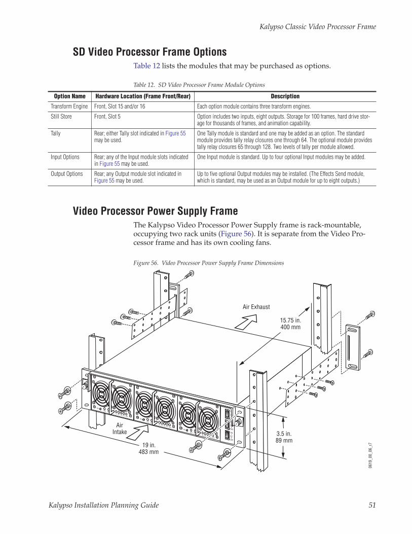
SD Video Processor Frame OptionsTable 12 lists the modules that may be purchased as options.
Video Processor Power Supply FrameThe Kalypso Video Processor Power Supply frame is rack-mountable, occupying two rack units (Figure 56). It is separate from the Video Pro-cessor frame and has its own cooling fans.
Figure 56. Video Processor Power Supply Frame Dimensions
Table 12. SD Video Processor Frame Module Options
Option Name Hardware Location (Frame Front/Rear) Description
Transform Engine Front, Slot 15 and/or 16 Each option module contains three transform engines.
Still Store Front, Slot 5 Option includes two inputs, eight outputs. Storage for 100 frames, hard drive stor-age for thousands of frames, and animation capability.
Tally Rear; either Tally slot indicated in Figure 55 may be used.
One Tally module is standard and one may be added as an option. The standard module provides tally relay closures one through 64. The optional module provides tally relay closures 65 through 128. Two levels of tally per module allowed.
Input Options Rear; any of the Input module slots indicated in Figure 55 may be used.
One Input module is standard. Up to four optional Input modules may be added.
Output Options Rear; any Output module slot indicated in Figure 55 may be used.
Up to five optional Output modules may be installed. (The Effects Send module, which is standard, may be used as an Output module for up to eight outputs.)
VADJ
ACG
20 40 60 80 100%
DCG
VADJ
ACG
20 40 60 80 100%
DCG
VADJ
ACG
20 40 60 80 100%
DCG
PS1
PS2
PS3
ON
DC
OFF
ON
DC
OFF
ON
DC
OFF
3.5 in.89 mm
19 in.483 mm
AirIntake
Air Exhaust
15.75 in.400 mm
0619
_00_
06_r
7
Kalypso Installation Planning Guide 51
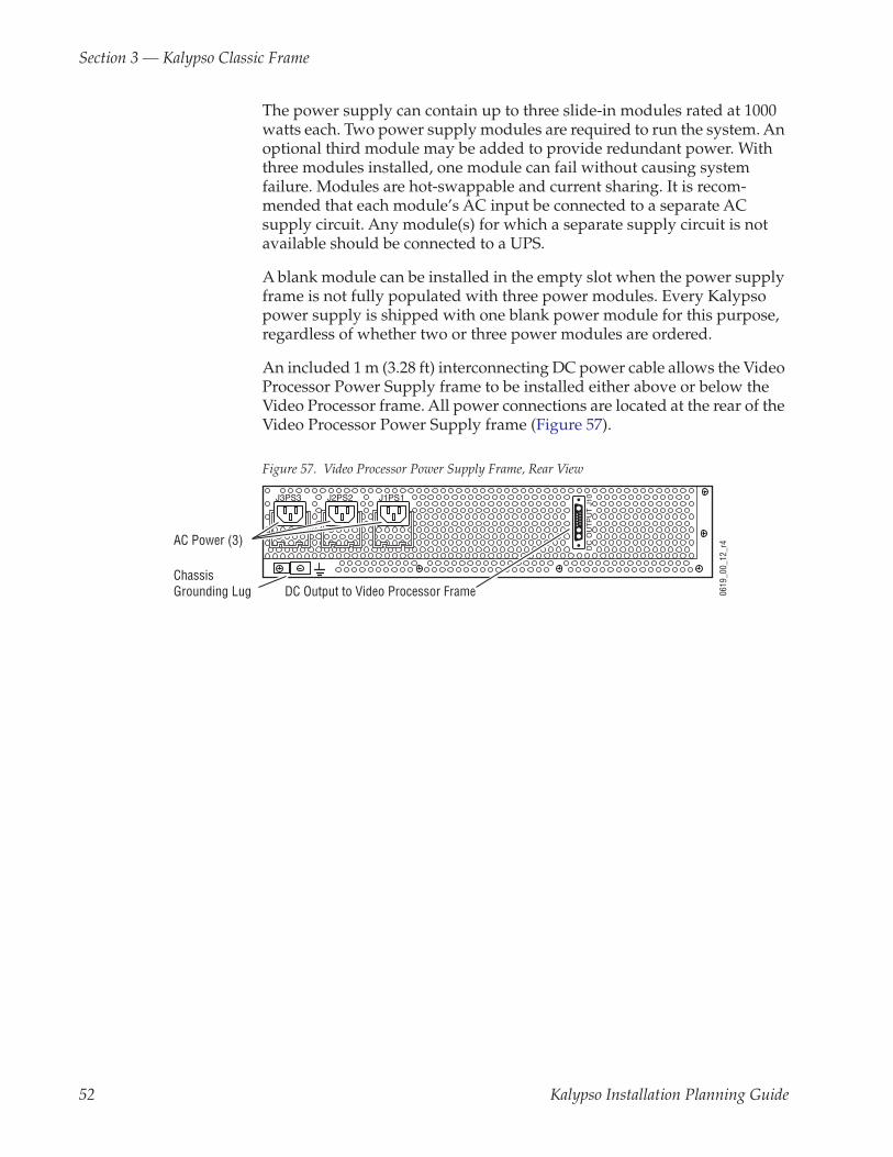
Section 3 — Kalypso Classic Frame
The power supply can contain up to three slide-in modules rated at 1000 watts each. Two power supply modules are required to run the system. An optional third module may be added to provide redundant power. With three modules installed, one module can fail without causing system failure. Modules are hot-swappable and current sharing. It is recom-mended that each module’s AC input be connected to a separate AC supply circuit. Any module(s) for which a separate supply circuit is not available should be connected to a UPS.
A blank module can be installed in the empty slot when the power supply frame is not fully populated with three power modules. Every Kalypso power supply is shipped with one blank power module for this purpose, regardless of whether two or three power modules are ordered.
An included 1 m (3.28 ft) interconnecting DC power cable allows the Video Processor Power Supply frame to be installed either above or below the Video Processor frame. All power connections are located at the rear of the Video Processor Power Supply frame (Figure 57).
Figure 57. Video Processor Power Supply Frame, Rear View
J3PS3 J2PS2 J1PS1
DC
OU
TP
UT
J10
0619
_00_
12_r
4
DC Output to Video Processor Frame
AC Power (3)
ChassisGrounding Lug
52 Kalypso Installation Planning Guide

Typical Kalypso Classic System Video Cabling
Typical Kalypso Classic System Video CablingTypical Kalypso Classic system connections are shown in Figure 58. Dif-ferent video and control wiring configurations may be used to meet indi-vidual facility requirements. All Kalypso system video inputs and outputs are configurable. Each input can be mapped to any Kalypso panel source select button, and any Kalypso system video signal can be mapped to any pair of output connectors.
Figure 58. Typical Kalypso Classic System
ProgramMonitor
PreviewMonitor
OtherMonitors
Program Out
Master Control/Transmitter
Video/Key (Effects Send)
FacilityRouterFrame
Cam 1
Cam 2
Cam 3
Video
Facility RouterControl
CameraShader
Video/Key (Effects Return)
Synchronous Serial (CPL)
NOTE: External Effects Send only on Kalypso Classic
Serial
ReferenceBlack
Aux Bus Outputs
ProfileVDR
Facility LAN
32-CrosspointRemote Aux Panel
Remote Control Surface #1
0618
_00_
17_r
13
Video/Key
Kalypso Main Control Surface
Kalypso Control
Ethernet Hub
32-CrosspointRemote Aux Panel
Remote Control Surface #2
Remote Control Surface #3
24-CrosspointRemote Aux Panel
Monitor
Monitor
SerialLAN
EthernetSwitch
Shot Box
KalypsoVideoProcessorFrame
Joystick DPM1
VTR
1Compatible DVEs: Krystal, GVeous/Dveous
Video or Key SignalControl Line
Override
Kalypso Installation Planning Guide 53

Section 3 — Kalypso Classic Frame
Kalypso Classic System Control CablingThe Kalypso system uses Ethernet, serial, parallel, and SCSI control. Tally and GPI control are also available (see Figure 59 and Figure 60). Refer to Table 13 on page 56 for a list of supplied cables.
4-M/E Kalypso Classic System
Figure 59. Typical 4-M/E Kalypso Classic System Control
Internal Control
Still Store LAN
Facility LAN
Facility LAN
Faci
lity
LAN
16 GPI In16 GPI Out8 Serial
Tally (Relay)
Kalypso Video Processor Frame
2 Synchronous Serial
Cont
rol
Syst
em
BootConfig BUFlash
Tally
HardDrive
Still
Sto
re
HardDrive
Remote Control Surface #3
24-CrosspointRemote Aux Panel
32-CrosspointRemote Aux Panel
Video or Key SignalControl LineSuite BoundaryControl Surface Boundary
USB
USB
To networkedimage sources
Ethernet Hub
NOTES:Control Panel, Facility, Still Store LAN: 10Base-T or 100Base-T EthernetRemote Aux Panels and Still Store are system options.
Point to Point SerialPorts 1-12RS-422/Serial Async
8162
_00_
07_r
1
Local Aux PanelMain Control Surface
Remote Control Surface #1
Kalypso Suite (Four Control Surfaces)
Remote Control Surface #2
32-CrosspointRemote Aux Panel
LANEthernetSwitch
Shot Box
(Provided with Flush Mount bracket.)
4-M/EMain Panel
Menu Panel
HardDrive
CD-ROMDrive
Optional Keyboard
Optional Mouse
Zip DriveMenuSystem Processor(Win 2000)
Optional CD-ROM
Real TimeProcessor
OptionalFuture SatellitePanels (1-12)
1-M/EMain Panel (option)
Real TimeProcessor
54 Kalypso Installation Planning Guide

Kalypso Classic System Control Cabling
2-M/E Kalypso Classic System
Figure 60. Typical 2-M/E Kalypso Classic System Control
Internal Control
Still Store LAN
Facility LAN
16 GPI In16 GPI Out8 Serial
Tally (Relay)
Kalypso Video Processor Frame
2 Synchronous Serial
Cont
rol
Syst
em
BootConfig BUFlash
Tally
HardDrive
Still
Sto
re
HardDrive
Remote Control Surface #3
24-CrosspointRemote Aux Panel
32-CrosspointRemote Aux Panel
32-CrosspointRemote Aux Panel
To networkedimage sources
LANEthernetSwitch
Ethernet Hub
0721
_02_
05_r
6
Remote Control Surface #1 Remote Control Surface #2
Kalypso Suite (Four Control Surfaces)
Shot Box
Facility LANFacility LAN
Video or Key SignalControl LineSuite BoundaryControl Surface Boundary
USB
USB
NOTES:Control Panel, Facility, Still Store LAN: 10Base-T or 100Base-T EthernetRemote Aux Panels and Still Store are system options.
Point to Point SerialPorts 1-12RS-422/Serial Async
Main Control Surface
(Provided with Flush Mount bracket.)
2-M/EMain Panel
Menu Panel
HardDrive
CD-ROMDrive
Optional Keyboard
Optional Mouse
Zip DriveMenuSystem Processor(Win 2000)
Optional CD-ROM
Real TimeProcessor
OptionalFuture SatellitePanels (1-12)
Local Aux Panel
Additional Menu Panel (option)
HardDrive
CD-ROMDrive
MenuSystem Processor(Win 2000)
Kalypso Installation Planning Guide 55
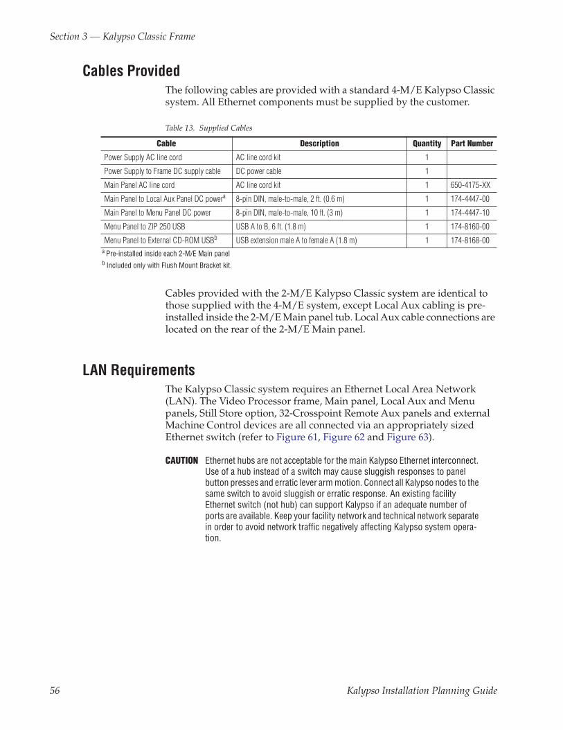
Section 3 — Kalypso Classic Frame
Cables ProvidedThe following cables are provided with a standard 4-M/E Kalypso Classic system. All Ethernet components must be supplied by the customer.
Cables provided with the 2-M/E Kalypso Classic system are identical to those supplied with the 4-M/E system, except Local Aux cabling is pre-installed inside the 2-M/E Main panel tub. Local Aux cable connections are located on the rear of the 2-M/E Main panel.
LAN RequirementsThe Kalypso Classic system requires an Ethernet Local Area Network (LAN). The Video Processor frame, Main panel, Local Aux and Menu panels, Still Store option, 32-Crosspoint Remote Aux panels and external Machine Control devices are all connected via an appropriately sized Ethernet switch (refer to Figure 61, Figure 62 and Figure 63).
CAUTION Ethernet hubs are not acceptable for the main Kalypso Ethernet interconnect. Use of a hub instead of a switch may cause sluggish responses to panel button presses and erratic lever arm motion. Connect all Kalypso nodes to the same switch to avoid sluggish or erratic response. An existing facility Ethernet switch (not hub) can support Kalypso if an adequate number of ports are available. Keep your facility network and technical network separate in order to avoid network traffic negatively affecting Kalypso system opera-tion.
Table 13. Supplied Cables
Cable Description Quantity Part Number
Power Supply AC line cord AC line cord kit 1
Power Supply to Frame DC supply cable DC power cable 1
Main Panel AC line cord AC line cord kit 1 650-4175-XX
Main Panel to Local Aux Panel DC powera
a Pre-installed inside each 2-M/E Main panel
8-pin DIN, male-to-male, 2 ft. (0.6 m) 1 174-4447-00
Main Panel to Menu Panel DC power 8-pin DIN, male-to-male, 10 ft. (3 m) 1 174-4447-10
Menu Panel to ZIP 250 USB USB A to B, 6 ft. (1.8 m) 1 174-8160-00
Menu Panel to External CD-ROM USBb
b Included only with Flush Mount Bracket kit.
USB extension male A to female A (1.8 m) 1 174-8168-00
56 Kalypso Installation Planning Guide

Kalypso Classic System Control Cabling
Refer to Table 14 for Ethernet specifications. All Ethernet components are supplied by the customer.
Ethernet Switches and HubsKalypso components rely primarily on Ethernet switches for LAN inter-connects. Remote Auxiliary panels may be connected directly to the Kalypso switch, or through an Ethernet hub. A hub is required only if there is a need to exceed 100 m (328 ft) between the Main panel and Video Pro-cessor frame (refer to Figure 62 and Figure 63). If a hub is used, connect hub to switch via the Uplink port, or through a peer-to-peer (crossover) cable. Reserve a port on Kalypso’s Ethernet switch if you will be utilizing an existing hub or switch (e.g., Omnibus LAN) (see Figure 62).
Note The number and type of components in your Kalypso system determines the size of the switch (number of ports) required. Refer to the following examples of system topography and the accompanying worksheet to determine the number of ports required for your system.
Figure 61. Example Topography Requiring an Eight Port Ethernet Switch
Table 14. Kalypso Classic System Ethernet Specifications
Cables
Typea
a 100Base-T required for core Kalypso system operation. 10Base-T used for 32-Crosspoint Remote Aux panels.
100Base-T and 10Base-T compatible. Category 5 or 6 cable, 8 conductor twisted pair.
Connectors RJ-45 male connector at each end of cable.
Lengthb
b Use a hub when necessary to exceed maximum cable runs.
100Base-T: 100 m (328 ft) maximum. 10Base-T: 300 m (984 ft) maximum.
Switch
Speed Dual: 10 and 100 Mb
Ports RJ-45 auto-negotiating 10/100 Mb; number of ports required is dependent upon system size.
Unmanaged Recommended. Configuration is not required, but does not provide remote monitoring capa-bility.
Managed May be used. Requires configuration, but offers remote monitoring capability.
Ethernet Hub1
32-XPT RemoteAux Panel (Option)
32-XPT RemoteAux Panel (Option)
32-XPT RemoteAux Panel (Option)
32-XPT RemoteAux Panel (Option)
Profile
Profile06
19_0
2_01
_r5
Video Processor Frame
Control System Facility LAN
Still Store
8 PortEthernetSwitch
1 Use hubs to exceed 100 m (328 ft.) cable limitations.
10BaseT Facility LAN100BaseT Facility LAN
10/100BaseT Facility Intranet
Local Aux Panel
Main PanelReal Time Processor
Menu PanelWindows Processor
Kalypso Installation Planning Guide 57
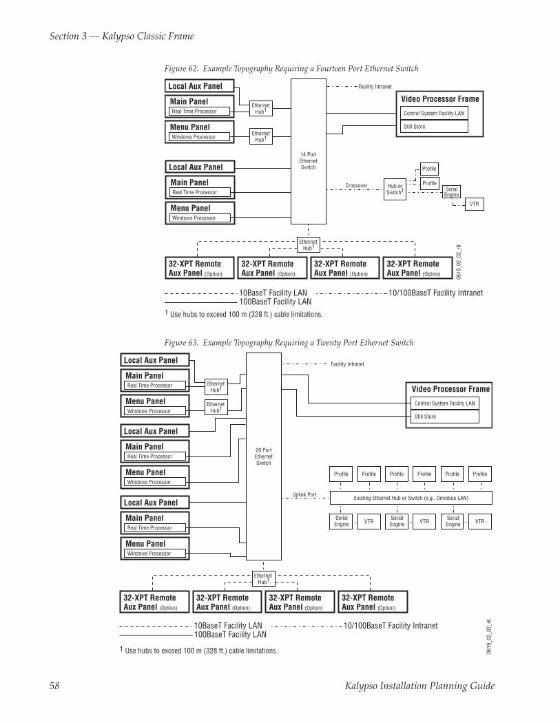
Section 3 — Kalypso Classic Frame
Figure 62. Example Topography Requiring a Fourteen Port Ethernet Switch
Figure 63. Example Topography Requiring a Twenty Port Ethernet Switch
ProfileHub orSwitch1
Crossover
Profile
SerialEngine
VTR
Ethernet Hub1
32-XPT RemoteAux Panel (Option)
32-XPT RemoteAux Panel (Option)
32-XPT RemoteAux Panel (Option)
32-XPT RemoteAux Panel (Option)
Facility Intranet
EthernetHub1
EthernetHub1
14 PortEthernetSwitch
0619
_02_
02_r
6
Video Processor Frame
Control System Facility LAN
Still Store
1 Use hubs to exceed 100 m (328 ft.) cable limitations.
10BaseT Facility LAN100BaseT Facility LAN
10/100BaseT Facility Intranet
Local Aux Panel
Main PanelReal Time Processor
Menu PanelWindows Processor
Local Aux Panel
Main PanelReal Time Processor
Menu PanelWindows Processor
Uplink Port
SerialEngine VTR
SerialEngine VTR
SerialEngine VTR
Profile Profile Profile Profile Profile Profile
Existing Ethernet Hub or Switch (e.g., Omnibus LAN)
Ethernet Hub1
32-XPT RemoteAux Panel (Option)
32-XPT RemoteAux Panel (Option)
32-XPT RemoteAux Panel (Option)
32-XPT RemoteAux Panel (Option)
Facility Intranet
Ethernet Hub1
Ethernet Hub1
20 PortEthernetSwitch
0619
_02_
03_r
6
Local Aux Panel
Main PanelReal Time Processor
Menu PanelWindows Processor
Local Aux Panel
Main PanelReal Time Processor
Menu PanelWindows Processor
Local Aux Panel
Main PanelReal Time Processor
Menu PanelWindows Processor
Video Processor Frame
Control System Facility LAN
Still Store
1 Use hubs to exceed 100 m (328 ft.) cable limitations.
10BaseT Facility LAN100BaseT Facility LAN
10/100BaseT Facility Intranet
58 Kalypso Installation Planning Guide

Kalypso Classic System Control Cabling
Standard System Components Ports Required Number of Components
Frame 3 x =
Main Control Panel 1 x =
Local Auxiliary Panel 1 x =
Menu Panel 1 x =
Kalypso Options
Facility Intranet 1a
a No port required if option not installed.
x =
32-Crosspoint Remote Aux Panel Hub 1a x (# of Hubs) =
Kalypso Machine Control Option
Profiles (Direct to Switch)b
b Connect devices directly to the Kalypso switch in small systems which have no other Omnibus components(Figure 61).
1a x =
Profiles (Hub or Switch)c
c An existing system will typically have a switch or hub which connects all Serial Engines, Profiles and Machine Controlsystem control panels and managers. Use an Uplink port on the Machine Control switch to make the switch-to-switchor switch-to-hub connection. Alternatively, one port on the switch can be connected to the Kalypso switch via a peer topeer (crossover) cable (Figure 63).
1a =
Existing Omnibus System (Hub or Switch)c 1a =
Total Number of Ports Required:
Kalypso Installation Planning Guide 59

Section 3 — Kalypso Classic Frame
Kalypso Classic Video Timing and DelayThe total delay of a video input to the switcher output can vary according to the relationship of the input to the switcher reference. The switcher will automatically autotime inputs that fall within an autotiming window (± B µs). Inputs must be within this range to be properly timed at the output. The calculation of the actual video delay of a specific input is the Nominal Switcher Delay minus the input time location within the autotiming window (the time location value can be zero, positive, or nega-tive). A timing diagram of the input autotiming window and various switcher delay values is provided in Figure 64.
Figure 64. Switcher Timing Diagram
Note For both 525 and 625 switcher operation, the approximate maximum switcher delay is one line of video.
• For inputs entering the switcher in zero time with the reference, the total delay through the switcher is the Nominal Switcher Delay (A µs).
• Inputs that reach the switcher at the latest point in the autotiming window (+B µs) will have a total delay that equals the time required for switcher processing. This value is the Minimum Switcher Delay (C µs).
• Inputs that reach the switcher at the earliest point in the autotiming window (-B µs) will have a total delay equal to the Nominal Switcher Delay (A µs) plus the autotiming window range. This value is the Maximum Switcher Delay value (D µs).
Delay values for a Kalypso system are given in Table 15.
Table 15. Kalypso System Video Delay Values
Nominal Switcher Delay A 53 µs
Serial Input Autotiming B +/- 10 µs
Minimum Switcher Delay C 43 µs
Maximum Switcher Delay D 63 µs
Nominal Output Timing
Serial InputAutotiming
Window+/- B µs
Nominal Reference Timing
8096
_03_
05_r
1
Nominal Switcher Delay A µs
Maximum Switcher Delay D µs
Minimum Switcher Delay C µs
- B µs + B µs0 µs
60 Kalypso Installation Planning Guide

Optional Kalypso Classic System Components
Optional Kalypso Classic System Components
Emergency BypassThe Emergency Bypass system provides basic switching capability should a component in the Kalypso system fail or lose power. The Emergency Bypass option uses an external router to perform the actual source selec-tions. Operator control is provided by the Local Aux panel. If the Kalypso system Main panel and/or the Video Processor frame fails, the Local Aux subpanel, Emergency Bypass frame, and facility router can still provide basic switching and keying capability.
An example of an installed Kalypso Emergency Bypass system is shown in Figure 65.
Figure 65. Emergency Bypass System
0721
_07_
59_r
6
Vide
o/Ke
y 2
RouterMatrix
RouterControl
KalypsoVideo
ProcessorFrame
KalypsoMainPanel
Local AuxPanel
Pgm 1 Out
Pgm 2 Out
Emergency Bypass(8900 TF Frame)
Bkgd
Vid
eo
Pvw
Vide
o/Ke
y 1
BypassRelay
Module
BypassFrame
MonitorModule
PowerSupply
BackupPower
(option)
BypassKeyer
Module
ExternalVideo & Key
Sources
Pgm
1
Pgm
2
Pvw
Video/Keyfrom Router
or Direct
RS-4
22
RS-4
22
BackupPowerSupply(option)
MenuPanel
Breakout Cable
Pvw Out
Pgm
Kalypso Installation Planning Guide 61

Section 3 — Kalypso Classic Frame
Emergency Bypass FrameThe 2 RU Emergency Bypass frame (Figure 66) fits a standard 19 in. (483 mm) equipment rack (See Specifications on page 9 for dimensions). Behind the front cover are ten slots for modules, plus one control slot and two slots for power supplies. The standard Kalypso Emergency Bypass option only uses two of these slots, typically slot 7 for the Relay Module and slot 8 for the Keyer module.
Figure 66. 8900TF Frame, Front View
The forced-air system has a front cover equipped with three fans for air cir-culation. The fan speed varies with the ambient frame temperature. Fan speed control voltage is generated on the Kalypso Emergency Bypass Frame Monitor module and can be disabled so that the fan runs at maximum speed only.
The right rear of the frame (Figure 67) includes ten groups of ten connectors (corresponding to the ten frame slots), which are used for input/output functions for inserted modules.
Figure 67. 8900TF Frame, Rear View
The power and communication section at the left rear of the frame provides RS-422 communications (the connector is labeled RS-232, but is RS-422 when the Kalypso Emergency Bypass Frame Monitor module is installed), AC power plug connections, and SMPTE Alarm BNC (J101) for fault reporting. The Ethernet connector is not used with the Kalypso Emergency Bypass option.
0619
_05_
03_r
0
LOCK LOCK
FAULT PS1 PS2
8900 Series
J1
DA10J1
DA10
0619
_05_
04_r
1
J1 J2
J3 J4
J5 J6
J7 J8J9 J10
IN
1
J2
J4
J6
J8
J1 J2
J3 J4
J5 J6
J7 J8J9 J10
IN
3
J1 J2
J3 J4
J5 J6
J7 J8J9 J10
IN
5
J1 J2
J3 J4
J5 J6
J7 J8J9 J10
IN
2
J1 J2
J3 J4
J5 J6
J7 J8J9 J10
IN
7
J1 J2
J3 J4
J5 J6
J7 J8J9 J10
IN
9
J1 J2
J3 J4
J5 J6
J7 J8J9 J10
IN
4
J2
J4
J6
J8
J1 J2
J3 J4
J5 J6
J7 J8J9 J10
IN
6
J2
J4
J6
J8
J1 J2
J3 J4
J5 J6
J7 J8J9 J10
IN
8
J2
J4
J6
J8
J1 J2
J3 J4
J5 J6
J7 J8J9 J10
IN
10
OUT
OUT
OUT
OUT
OUT
OUT
OUT
OUT
OUT
OUT
SMPTE
ALARM
J101
RS232
J102
ETHERNETJ103
J1 J2
62 Kalypso Installation Planning Guide

Optional Kalypso Classic System Components
Frame RestrictionsAlthough the Emergency Bypass frame is derived from Grass Valley Group’s 8900 Series Modular frame, it has been designed specifically for the Kalypso system, making the frame suitable only for Emergency Bypass modules.
CAUTION Do not plan to install any other types of 8900 series modules in the Emer-gency Bypass frame.
Power Supply OptionsRedundant power options include:
• Redundant power supply for the Emergency Bypass frame, and
• Redundant power for the Local Aux panel: a 4-M/E Local Aux panel can use up to two redundant power bricks while only one can be used for a 2-M/E Local Aux subpanel.
See the Kalypso Emergency Bypass Option Installation Instructions and the 8900 Series Modular and SMS 7000 Router documentation sets for detailed information. Online documentation is available on the Grass Valley Group web site. The URL for the Grass Valley Group website is found on the copy-right page at the front of this manual.
8950ADC Module - 4:4:4 Chroma Key ProcessingThe 8950ADC module in Grass Valley Group’s 8900 modular product line can be configured to support full bandwidth chroma key processing on the Kalypso Classic system.
OverviewIn CCIR-601 digital signals, luminance (Y) is sampled at twice the rate of the two chrominance signals (Cr, Cb) – hence the 4:2:2 designation to indi-cate the sampling rate for Y:Cr:Cb respectively. So every pixel on the screen has a unique luminance value, but color information is transmitted for every other pixel. The receiving device typically repeats one chrominance value for two pixels, or generates the missing values by some form of inter-polation. In neither case is the information regained that was lost by the original filtering to 4:2:2. This works for most video processing and trans-mission applications since the human eye is not nearly as responsive to color changes as it is to luminance changes. However, in chroma key pro-cessing, the user is selecting a particular color out of a scene, so chromi-nance bandwidth is paramount to achieving the best results.
In most cases, you can achieve excellent results even when using a 4:2:2 signal as both the video fill and the chroma key source. Pre-processing in the chroma keyer uses interpolation as described above in order to have a
Kalypso Installation Planning Guide 63

Section 3 — Kalypso Classic Frame
chrominance value for each pixel. In some critical applications, however, there is something to be gained by utilizing unique chrominance values for each pixel for the highest input resolution when computing the chroma key.
It is important to note that the chroma keyer always does 4:4:4 processing. However, if the key source is a 4:2:2 signal, the chroma keyer computes the missing samples using interpolation. In the case of full bandwidth key sources, the chroma keyer actually receives chrominance samples for every pixel location from the external device.
Kalypso SolutionThe Kalypso Video Production Center has a superior solution for full band-width chroma keys which keeps analog-to-digital conversion out of the digital switcher chassis and minimizes the number of input BNCs con-sumed by each 0:4:4 source. In addition, customers can accommodate any number of 0:4:4 sources as desired — limited only by the number of avail-able digital inputs.
The Kalypso Video Production Center keeps analog signals out of the digital switcher chassis, but uses only two SDI input BNCs for a full band-width chroma key. The video fill is still a CCIR-601 standard video signal which comes in on one of Kalypso’s inputs. The key source comes in on a separate input BNC.
The 8950ADC module has a special 0:4:4 mode that takes the RGB analog input from a camera or other chroma key source and converts it to a special 0.4.4. signal format for Kalypso. One 8950ADC module is used for each full bandwidth chroma key source.
As far as the Kalypso input board and crosspoint system know, the key source looks just like any other standard CCIR-601 video signal. However, all of the 0:4:4 chrominance samples you need to do a full bandwidth chroma key are present in the luminance and chrominance data bits of the CCIR-601 signal.
Note This special 0:4:4 chroma key signal cannot be viewed on a standard digital waveform monitor.
Any pair of Kalypso inputs may be used for a 4:2:2 / 0:4:4 chroma key fill/source pair, so the total number of full bandwidth chroma key inputs is limited only by the total number of Kalypso inputs available.
See the 8950ADC Analog to Component Digital Converter Instruction manual for detailed information. Online documentation is available on the Grass Valley Group web site. The URL for the Grass Valley Group website is found on the copyright page at the front of this manual.
64 Kalypso Installation Planning Guide

SD Video Processor Frame Pinouts
SD Video Processor Frame Pinouts
Control I/O Module Table 16. RS-232 Port
COM1 Port - J4 Pin Function Pin Function
1 Chassis Ground 14 Not Used
2 RXD 15 Not Used
3 TXD 16 Not Used
4 RTS 17 Not Used
5 CTS 18 Not Used
6 DSR 19 Not Used
7 Chassis Ground 20 DTR
8 DCD 21 Not Used
9 Not Used 22 Not Used
10 Not Used 23 Not Used
11 Not Used 24 Not Used
12 Not Used 25 Not Used
13 Not Used
Pin 1
Pin 13
Pin 14
Pin 25
D-25 Female
Kalypso Installation Planning Guide 65

Section 3 — Kalypso Classic Frame
Table 17. GPI Inputs
GPI Inputs Port – J5 Pin Function Pin Function
1 Chassis Ground 20 IN 1 B
2 IN 1 A 21 IN 2 B
3 IN 2 A 22 IN 3 B
4 IN 3 A 23 IN 4 B
5 IN 4 A 24 Chassis Ground
6 IN 5 A 25 IN 5 B
7 IN 6 A 26 IN 6 B
8 IN 7 A 27 IN 7 B
9 IN 8 A 28 IN 8 B
10 Chassis Ground 29 IN 9 B
11 IN 9 A 30 IN 10 B
12 IN 10 A 31 IN 11 B
13 IN 11 A 32 IN 12 B
14 IN 12 A 33 Chassis Ground
15 IN 13 A 34 IN 13 B
16 IN 14 A 35 IN 14 B
17 IN 15 A 36 IN 15 B
18 IN 16 A 37 IN 16 B
19 Chassis Ground
Notes:Inputs are opto-isolated.A and B are polarity independent.Apply from 5 to 24 volts to A and B to turn on.
Pin 1
Pin 19
Pin 20
Pin 37
D-37 Female
66 Kalypso Installation Planning Guide

SD Video Processor Frame Pinouts
Table 18. GPI Outputs
GPI Outputs Port – J6 Pin Function Pin Function
1 Chassis Ground 20 Out 1 B
2 Out 1 A 21 Out 2 B
3 Out 2 A 22 Out 3 B
4 Out 3 A 23 Out 4 B
5 Out 4 A 24 Chassis Ground
6 Out 5 A 25 Out 5 B
7 Out 6 A 26 Out 6 B
8 Out 7 A 27 Out 7 B
9 Out 8 A 28 Out 8 B
10 Chassis Ground 29 Out 9 B
11 Out 9 A 30 Out 10 B
12 Out 10 A 31 Out 11 B
13 Out 11 A 32 Out 12 B
14 Out 12 A 33 Chassis Ground
15 Out 13 A 34 Out 13 B
16 Out 14 A 35 Out 14 B
17 Out 15 A 36 Out 15 B
18 Out 16 A 37 Out 16 B
19 Chassis Ground
Notes:Outputs are normally open relay closures between A and B.30 volts maximum open circuit between A and B.1 amp maximum.
Table 19. Serial Ports
RS-422 Ports Pin CPL Ports - J7, J8 J9, J10, J11, J12, J13, J14, J15, J16
Serial Ports
1 Chassis Ground Chassis Ground
2 RX - RX -
3 TX + TX +
4 Chassis Ground Chassis Ground
5 Not Used Not Used
6 Common (Ground) Common (Ground)
7 RX + RX +
8 TX - TX -
9 Chassis Ground Chassis Ground
Notes:For Ports J9 – J16 only: The data directions specified on pins 2&3 and 7&8 as RX and TX may be reversed in software configuration.
Pin 1
Pin 19
Pin 20
Pin 37
D-37 Female
Pin 5
Pin 6
Pin 9
D-9 Female
Pin 1
Kalypso Installation Planning Guide 67

Section 3 — Kalypso Classic Frame
Table 20. Tally Ports
Tally Ports Pin Tally Module 1Tally 1-32, J1
Tally Module 1Tally 33-64, J2
Tally Module 2Tally 65-96, J1
Tally Module 2Tally 97-128, J2
1 Tally 1 Tally 33 Tally 65 Tally 97
2 Tally 2 Tally 34 Tally 66 Tally 98
3 Tally 3 Tally 35 Tally 67 Tally 99
4 Tally 4 Tally 36 Tally 68 Tally 100
5 Tally 5 Tally 37 Tally 69 Tally 101
6 Tally 6 Tally 38 Tally 70 Tally 102
7 Tally 7 Tally 39 Tally 71 Tally 103
8 Tally 8 Tally 40 Tally 72 Tally 104
9 Tally 9 Tally 41 Tally 73 Tally 105
10 Tally 1 0 Tally 42 Tally 74 Tally 106
11 Tally 11 Tally 43 Tally 75 Tally 107
12 Tally 12 Tally 44 Tally 76 Tally 108
13 Tally 13 Tally 45 Tally 77 Tally 109
14 Tally 14 Tally 46 Tally 78 Tally 110
15 Tally 15 Tally 47 Tally 79 Tally 111
16 Tally 16 Tally 48 Tally 80 Tally 112
17 Tally 17 Tally 49 Tally 81 Tally 113
18 Tally 18 Tally 50 Tally 82 Tally 114
19 Tally 19 Tally 51 Tally 83 Tally 115
20 Tally 20 Tally 52 Tally 84 Tally 116
21 Tally 21 Tally 53 Tally 85 Tally 117
22 Tally 22 Tally 54 Tally 86 Tally 118
23 Tally 23 Tally 55 Tally 87 Tally 119
24 Tally 24 Tally 56 Tally 88 Tally 120
25 Tally 25 Tally 57 Tally 89 Tally 121
26 Tally 26 Tally 58 Tally 90 Tally 122
27 Tally 27 Tally 59 Tally 91 Tally 123
28 Tally 28 Tally 60 Tally 92 Tally 124
29 Tally 29 Tally 61 Tally 93 Tally 125
30 Tally 3 0 Tally 62 Tally 94 Tally 126
31 Tally 31 Tally 63 Tally 95 Tally 127
32 Tally 32 Tally 64 Tally 96 Tally 128
33 Not Used Not Used Not Used Not Used
34 Not Used Not Used Not Used Not Used
35 Not Used Not Used Not Used Not Used
36 Tally CommonTally 1-32
Tally CommonTally 33-64
Tally CommonTally 65-96
Tally CommonTally 97-128
37 Chassis Ground Chassis Ground Chassis Ground Chassis Ground
Pin 1
Pin 19
Pin 20
Pin 37
D-37 Female
68 Kalypso Installation Planning Guide

SD Video Processor Frame Pinouts
Reference In ModuleTable 21. Alarms
Alarms Port - J4 Pin FunctionAlarm Status
Pins Normal Alarm
1 Normally Closed A 1, 3 Closed Open
2 Normally Open A 2, 3 Open Closed
3 COM A 4, 6 Closed Open
4 Normally Closed B 5, 6 Open Closed
5 Normally Open B
6 COM B
7 Not Used
8 Not Used
9 Not Used
10 Not Used
11 Not Used
12 Not Used
13 Not Used
14 Not Used
15 Chassis Ground
Notes:Relay contacts A and B are totally isolated from each other.
Table 22. Linear Timecode
Linear Timecode Port - J3 Pin Function
1 Not Used
2 Not Used
3 Not Used
4 Chassis Ground
5 LTC +
6 Not Used
7 Chassis Ground
8 Not Used
9 LTC –
Notes:This port is currently unused.
Pin 8
Pin 9
Pin 15
D-15 Female
Pin 1
Pin 5
Pin 6
Pin 9
D-9 Female
Pin 1
Kalypso Installation Planning Guide 69

Section 3 — Kalypso Classic Frame
70 Kalypso Installation Planning Guide

Section 4Kalypso HD Frame
HD Video Processor FrameThe Kalypso HD Video Processor frame is a 13 rack unit chassis which mounts in a standard 483 mm (19 in.) rack (Figure 68 on page 72). An addi-tional 2 rack unit power supply is also required (Figure 56 on page 51).
The Video Processor frame has a built-in cooling system consisting of a fan/plenum mounted in the upper section of the frame, and an air filter in the lower section. Cooling air is drawn in at the lower sides of the frame, up through the filter and modules, then expelled out the back of the fan/plenum. In racks with forced air cooling that enters from above, heated exhaust air may be forced down to the air intakes and cause elevated frame temperatures. In these cases installing ducts or baffles to keep airflows sep-arate is advised.
Kalypso Installation Planning Guide 71

Section 4 — Kalypso HD Frame
Figure 68. HD Video Processor Frame Dimensions
The Kalypso HD Video Processor frame has a front bay (Figure 69) that provides access to the Fan Drawer, Air Filter, and removable modules such as the Control, Crosspoint, M/E, and Transform Engines. Some of the modules shown are optional and may not be included in your system con-figuration.
CAUTION For clarity, the Kalypso HD Video Processor frame is shown with the front door removed. The front door must remain in place and closed during normal system operation to maintain maximum cooling efficiency.
17 in.432 mm
Air Exhaust
22.75 in578 mm
19.625 in.495 mm
0.93 in.24 mm
AirIntake
19 in.483 mm
0619
_08_
75_r
0
Air Intake(both sides)
72 Kalypso Installation Planning Guide

HD Video Processor Frame
Figure 69. HD Video Processor Frame, Front View
0619
_08_
76_r
3
OFF
ON
Fan Drawer
Keyboard*
VGA Port*
Floppy DiskDrive*
* For Service Personnel Use Only
ControlProcessor
PowerSwitch
Frame ResetButton
COM BootDial
Slot 1ControlModule
Slot 2Still StoreModule
(optional)
Air Filter Slot 4 - 7M/E Modules
(M/E 3, 2, 1, PGM/PST)
Slot 8 - 9Transform Engine
Modules (2)(optional)
Slots 3Crosspoint
Module
Kalypso Installation Planning Guide 73

Section 4 — Kalypso HD Frame
Power, control, and video connections are made at the rear of the Video Processor frame (Figure 70).
Figure 70. HD Video Processor Frame, Rear View
Air Exhaust
15 Standard Inputs(with up to 5
15 Input options for 90 inputs total)
48 ProgrammableOutputs
(24 2-M/E48 4-M/E)
DC Input from Power Supply
SD Reference Looping Input
HD Reference Looping Input
Ethernet LANConnections(6 external ports)
0619
_08_
77_r
1
2 HDLC SerialConnectors for CPL Interface
Diagnostic Port
Timecode ReaderInput
GPI InGPI Out
Tally 1-32
Tally 33-64
Outputs Inputs
LAN
TimecodeIn
SD HD
Analog Reference In
DC In
GPI In
Serial 5 Serial 6 Serial 7 Serial 8
Serial 1 Serial 2 Serial 3 Serial 4
Diagnostic HDLC 1 HDLC 2
GPI OutTally1-32
Tally33-64
1 1
2
3
4
5
6
7
8
9
10
11
12
13
14
15
16
17
18
19
20
21
22
23
24
25
26
27
28
29
30
31
32
33
34
53
36
37
38
39
40
41
42
43
44
45
46
47
48
49
50
51
52
53
54
55
56
57
58
59
60
61
1 2 3
4 5 6
62
63
64
65
66
67
68
69
70
71
72
73
74
75
76
77
78
79
80
81
82
83
84
85
86
87
88
89
90
2
3
4
5
6
7
8
9
10
11
12
13
14
15
16
17
18
19
20
21
22
23
24
25
26
27
28
29
30
31
32
33
34
35
36
37
38
39
40
41
42
43
44
45
46
47
48
8 configurableSerial Ports for Editor, Peripheral Bus II, andRemote Aux Panels
Chassis Grounding
Lug
74 Kalypso Installation Planning Guide

HD Video Processor Frame
HD Video Processor Frame Hardware OptionsTable 23 lists the modules that may be purchased as options.
Emergency Bypass OptionThe Emergency Bypass system provides basic switching capability should a component in the Kalypso system fail or lose power. This option operates with SD video signals and so does not support any HD video formats. This option is appropriate for Kalypso Duo systems, and for Kalypso HD systems only when operating in SD mode. See Emergency Bypass on page 61 for more information about this option.
Video Processor Power Supply FrameThe Kalypso HD Video Processor Power Supply frame is rack-mountable, occupying two rack units (Figure 56 on page 51). It is separate from the Video Processor frame and has its own cooling fans.
The power supply can contain up to three slide-in modules rated at 1000 watts each. Two power supply modules are required to run the system. An optional third module may be added to provide redundant power. With three modules installed, one module can fail without causing system failure. Modules are hot-swappable and current sharing. It is recom-mended that each module’s AC input be connected to a separate AC supply circuit. Any module(s) for which a separate supply circuit is not available should be connected to a UPS.
A blank module can be installed in the empty slot when the power supply frame is not fully populated with three power modules. Every Kalypso power supply is shipped with one blank power module for this purpose, regardless of whether two or three power modules are ordered.
An included 1 m (3.28 ft) interconnecting DC power cable allows the Video Processor Power Supply frame to be installed either above or below the Video Processor frame. All power connections are located at the rear of the Video Processor Power Supply frame (Figure 57 on page 52).
Table 23. HD Video Processor Frame Module Options
Option Name Hardware Location (Frame Front/Rear) Description
Transform Engine Slot 8 and 9 Each option module contains three transform engines.
Still Store Slot 2 Option includes two inputs, eight outputs. Storage for 100 frames, hard drive stor-age for thousands of frames, and animation capability.
Kalypso Installation Planning Guide 75

Section 4 — Kalypso HD Frame
Typical Kalypso HD System Video CablingTypical Kalypso HD system connections are shown in Figure 71. Different video and control wiring configurations may be used to meet individual facility requirements. All Kalypso system video inputs and outputs are configurable. Each input can be mapped to any Kalypso panel source select button, and any Kalypso system video signal can be mapped to any pair of output connectors.
Figure 71. Typical Kalypso HD System
Serial Ports(8 total)
Program Out
KalypsoHD VideoProcessorFrame
HDTV ProgramMonitor
HDTV PreviewMonitor
Other HDTVMoni tors
Master Control/Transmitter
FacilityHD RouterFrame
HDTVCam 1
HDTVCam 2
HDTVCam 3
Video
Video
Facility RouterControl
CameraShader
Serial
Serial
Serial
Serial
Serial
SD or HDReference
Aux Bus Outputs
ProfileXP
32-CrosspointRemote Aux Panel
Remote Control Surface #1
0619
_08_
78r0
Video/Key
Kalypso Main Control Surface
Kalypso Control
Ethernet Switch
32-CrosspointRemote Aux Panel
Remote Control Surface #2
Remote Control Surface #3
24-CrosspointRemote Aux Panel
HDTV Monitor
HDTV Monitor
Shot Box
Joystick
VTR
Video or Key SignalControl Line
Override EthernetLANSwitch8 Ports(6 external/2 internal)
StillStore
(3 LAN Ports)
(1 LAN Port)
Editor
SerialTally
FrameCPU
1 LAN Port(internal)
1 LAN Port(internal)
76 Kalypso Installation Planning Guide

Kalypso HD System Control Cabling
Kalypso HD System Control CablingThe Kalypso HD system uses Ethernet, serial, parallel, and SCSI control. Tally and GPI control are also available (see Figure 72 and Figure 73). Refer to Table 24 on page 79 for a list of supplied cables.
4-M/E Kalypso HD System
Figure 72. Typical 4-M/E Kalypso HD System Control
Internal Control
Still Store LAN
16 GPI In16 GPI Out
8 Serial
Tally 1-32 and 33-64 (Relay)
Kalypso HD Video Processor Frame
2 Synchronous Serial Cont
rol
Syst
em
CPUBootConfig BUFlash
Tally
HardDrive
Still
Sto
re
HardDrive
Remote Control Surface #3
24-CrosspointRemote Aux Panel
Video or Key SignalControl LineSuite BoundaryControl Surface Boundary
USB
USB
To networkedimage sources
Ethernet Switch
NOTES:Control Panel, Facility, Still Store LAN: 10Base-T or 100Base-T EthernetRemote Aux Panels and Still Store are system options.
Point to Point SerialPorts 1-12RS-422/Serial Async
0619
_08_
79_r
0
Local Aux Panel
Main Control Surface
32-CrosspointRemote Aux Panel
Remote Control Surface #1
Kalypso Suite (Four Control Surfaces)
Remote Control Surface #2
32-CrosspointRemote Aux Panel
LANEthernetSwitch
Shot Box
(Provided with Flush Mount bracket.)
Menu Panel
HardDrive
CD-ROMDrive
Optional Keyboard
Optional Mouse
Zip DriveMenuSystem Processor(Win 2000)
Optional CD-ROM
OptionalFuture SatellitePanels (1-12)
4-M/EMain Panel
Real TimeProcessor
1-M/EMain Panel (option)
Real TimeProcessor
Kalypso Installation Planning Guide 77

Section 4 — Kalypso HD Frame
2-M/E Kalypso HD System
Figure 73. Typical 2-M/E Kalypso HD System Control
Internal Control
Still Store LAN
Facility LAN
16 GPI In16 GPI Out
8 Serial
Tally 1-32 and 33-64 (Relay)
Kalypso HD Video Processor Frame
2 Synchronous Serial Cont
rol
Syst
em
CPUBootConfig BUFlash
Tally
HardDrive
Still
Sto
re
HardDrive24-Crosspoint
Remote Aux Panel
Video or Key SignalControl LineSuite BoundaryControl Surface Boundary
USB
USB
To networkedimage sources
Ethernet Switch
NOTES:Control Panel, Facility, Still Store LAN: 10Base-T or 100Base-T EthernetRemote Aux Panels and Still Store are system options.
Point to Point SerialPorts 1-12RS-422/Serial Async
0619
_08_
80_r
0
Main Control Surface
32-CrosspointRemote Aux Panel
Remote Control Surface #1
Kalypso Suite (Three Control Surfaces)
Remote Control Surface #2
32-CrosspointRemote Aux Panel
LANEthernetSwitch
Shot Box
(Provided with Flush Mount bracket.)
Menu Panel
HardDrive
CD-ROMDrive
Optional Keyboard
Optional Mouse
Zip DriveMenuSystem Processor(Win 2000)
Optional CD-ROM
OptionalFuture SatellitePanels (1-12)
2-M/EMain Panel
Real TimeProcessor
Local Aux Panel
Additional Menu Panel (option)
HardDrive
CD-ROMDrive
MenuSystem Processor(Win 2000)
78 Kalypso Installation Planning Guide

Kalypso HD System Control Cabling
Cables ProvidedThe following cables are provided with a standard 4-M/E Kalypso HD system. All Ethernet components must be supplied by the customer.
Cables provided with the 2-M/E Kalypso HD system are identical to those supplied with the 4-M/E system, except Local Aux cabling is pre-installed inside the 2-M/E Main panel tub. Local Aux cable connections are located on the rear of the 2-M/E Main panel.
Kalypso HD LAN RequirementsKalypso components rely primarily on Ethernet switches for LAN inter-connects. The Kalypso HD Video Processor frame contains a built-in 8 port Ethernet switch (6 external ports and 2 internal ports for the Frame CPU and the Still Store) providing convenient connections for system compo-nents. The built-in switch automatically senses Ethernet cable wiring, so there is no need to use crossover cables. Remote Aux panels may be con-nected directly to the internal Video Processor frame switch, or through an external Ethernet switch or hub. A hub is required only if there is a need to exceed 100 m (328 ft) between the system component and Video Processor frame (refer to Figure 75 and Figure 76).
Note The number and type of components in your Kalypso system determines the size of any additional switches (number of ports) required. Refer to the fol-lowing examples of system topography and the accompanying worksheet to determine the number of ports required for your system.
Table 24. Supplied Cables
Cable Description Quantity Part Number
Power Supply AC line cord AC line cord kit 1
Power Supply to Frame DC supply cable DC power cable 1
Main Panel AC line cord AC line cord kit 1 650-4175-XX
Main Panel to Local Aux Panel DC powera
a Pre-installed inside each 2-M/E Main panel
8-pin DIN, male-to-male, 2 ft. (0.6 m) 1 174-4447-00
Main Panel to Menu Panel DC power 8-pin DIN, male-to-male, 10 ft. (3 m) 1 174-4447-10
Menu Panel to ZIP 250 USB USB A to B, 6 ft. (1.8 m) 1 174-8160-00
Menu Panel to External CD-ROM USBb
b Included only with Flush Mount Bracket kit.
USB extension male A to female A (1.8 m) 1 174-8168-00
Kalypso Installation Planning Guide 79

Section 4 — Kalypso HD Frame
Kalypso Control Surface Facility LANKalypso system components communicate over a Control Surface Facility LAN using an 8 port Ethernet switch built in to the HD Video Processor frame. This plug and play configuration allows Kalypso components to communicate with one another with no IP address configuration necessary using factory default settings.
The Kalypso Control Surface LAN is illustrated in Figure 74. In this config-uration, the Main panel, Menu panel, Local Aux panel, uplink from an Ethernet hub with four Remote Aux panels, and an additional Menu panel option are connected directly to the Video Processor frame Ethernet switch. Up to 6 external ports (LAN 1-6) can be accessed on the rear of the Video Processor frame for connecting system components to the Control Surface LAN. Two internal ports provide Video Processor frame CPU and the Still Store option LAN connections.
The Kalypso Control Surface Facility LAN may then be interfaced to an existing network by connecting a Video Processor frame LAN port to an external switch or gateway as described in the next sections.
Figure 74. Example Topography of Kalypso Control Surface Facility LAN
Ethernet Hub1
32-XPT RemoteAux Panel (Option)
32-XPT RemoteAux Panel (Option)
32-XPT RemoteAux Panel (Option)
32-XPT RemoteAux Panel (Option)
0619
_08_
83_r
0
1 Use hubs to exceed 100 m (328 ft.) cable limitations.
10BaseT Facility LAN100BaseT Facility LAN
Local Aux Panel
Main PanelReal Time Processor
Menu PanelWindows Processor
Kalypso HD Video Processor Frame
Still StoreLAN 7 - Internal
Frame CPULAN 8 - Internal
Built-in 8 Port Ethernet Switch
(6 external ports/2 internal ports)
LAN 1
LAN 2
LAN 3
LAN 4
LAN 5
LAN 6
AdditionalMenu Panel (option)
Windows Processor
To External Switch or Gateway
80 Kalypso Installation Planning Guide

Kalypso HD System Control Cabling
Connecting Kalypso to An Existing LANThe Kalypso system can be connected to an existing LAN in your facility (e.g., Omnibus LAN), in a number of different ways depending on the number of system components, the existing network structure, and the needs of the user.
In the example in Figure 75, the Kalypso system components are connected to an external 8 port switch then interface to the Video Processor frame internal switch and the existing LAN.
Figure 75. Example Topography Requiring an Eight Port Ethernet Switch
In Figure 76 on page 82, a more complex network is illustrated requiring multiple switches and/or hubs.
ProfileHub orSwitch1
Profile
SerialEngine
VTREthernet
Hub1
32-XPT RemoteAux Panel (Option)
32-XPT RemoteAux Panel (Option)
32-XPT RemoteAux Panel (Option)
32-XPT RemoteAux Panel (Option)
Facility Intranet
8 PortEthernetSwitch
0619
_08_
81r0
1 Use hubs to exceed 100 m (328 ft.) cable limitations.
10BaseT Facility LAN100BaseT Facility LAN
10/100BaseT Facility Intranet
Local Aux Panel
Main PanelReal Time Processor
Menu PanelWindows Processor
Local Aux Panel
Main PanelReal Time Processor
Menu PanelWindows Processor
Kalypso HD Video Processor Frame
Still StoreLAN 7 - Internal
Frame CPULAN 8 - Internal
Built-in 8 Port Ethernet Switch
(6 external ports/2 internal ports)
Ethernet Hub1
Ethernet Hub1
Kalypso Installation Planning Guide 81

Section 4 — Kalypso HD Frame
Figure 76. Example Topography Requiring a Twenty Port Ethernet Switch
Standard System Components Ports Required Number of Components
Frame 1 x =
Main Control Panel 1 x =
Local Auxiliary Panel 1 x =
Menu Panel 1 x =
Kalypso Options
Facility Intranet 1a
a No port required if option not installed.
x =
32-Crosspoint Remote Aux Panel Hub 1a x (# of Hubs) =
Kalypso Machine Control Option
Profiles (Direct to Switch)b
b Connect devices directly to the Kalypso switch in small systems which have no other Omnibus components(Figure 74).
1a x =
Profiles (Hub or Switch)c
c An existing system will typically have a switch or hub which connects all Serial Engines, Profiles and Machine Controlsystem control panels and managers. Use an Uplink port on the Machine Control switch to make the switch-to-switchor switch-to-hub connection. Alternatively, one port on the switch can be connected to the Kalypso switch (Figure 76).
1a =
Existing Omnibus System (Hub or Switch)c 1a =
Total Number of Ports Required:
SerialEngine VTR
SerialEngine VTR
SerialEngine VTR
Profile Profile Profile Profile Profile Profile
Existing Ethernet Hub or Switch (e.g., Omnibus LAN)
Ethernet Hub1
32-XPT RemoteAux Panel (Option)
32-XPT RemoteAux Panel (Option)
32-XPT RemoteAux Panel (Option)
32-XPT RemoteAux Panel (Option)
Ethernet Hub1
EthernetSwitch
0619
_08_
82r0
Local Aux Panel
Main PanelReal Time Processor
Menu PanelWindows Processor
Local Aux Panel
Main PanelReal Time Processor
Menu PanelWindows Processor
Local Aux Panel
Main PanelReal Time Processor
Menu PanelWindows Processor
Kalypso HD Video Processor Frame
Still Store
Frame CPU
1 Use hubs to exceed 100 m (328 ft.) cable limitations.
10BaseT Facility LAN100BaseT Facility LAN
10/100BaseT Facility Intranet
8 Port Ethernet Switch(6 external ports and
2 internal ports)
PC running Kalypso Application
Windows Processor
Ethernet Hub1
82 Kalypso Installation Planning Guide

HD Video Processor Frame Pinouts
HD Video Processor Frame Pinouts
Table 25. Linear Timecode
Linear Timecode Port Pin Function
1 Not Used
2 Not Used
3 Not Used
4 Chassis Ground
5 LTC +
6 Not Used
7 Chassis Ground
8 Not Used
9 LTC –
Notes:This port is currently unused.
Table 26. Serial Ports
RS-422 Ports Pin HDLC Ports Serial Ports 1-8
1 Chassis Ground Chassis Ground
2 RX - RX -
3 TX + TX +
4 Chassis Ground Chassis Ground
5 Not Used Not Used
6 Common (Ground) Common (Ground)
7 RX + RX +
8 TX - TX -
9 Chassis Ground Chassis Ground
Notes:For Serial Ports only: The data directions specified on pins 2&3 and 7&8 as RX and TX may be reversed in software configuration.
Pin 5
Pin 6
Pin 9
D-9 Female
Pin 1
Pin 5
Pin 6
Pin 9
D-9 Female
Pin 1
Kalypso Installation Planning Guide 83

Section 4 — Kalypso HD Frame
Table 27. GPI Inputs
GPI Inputs Port Pin Function Pin Function
1 Chassis Ground 20 IN 1 B
2 IN 1 A 21 IN 2 B
3 IN 2 A 22 IN 3 B
4 IN 3 A 23 IN 4 B
5 IN 4 A 24 Chassis Ground
6 IN 5 A 25 IN 5 B
7 IN 6 A 26 IN 6 B
8 IN 7 A 27 IN 7 B
9 IN 8 A 28 IN 8 B
10 Chassis Ground 29 IN 9 B
11 IN 9 A 30 IN 10 B
12 IN 10 A 31 IN 11 B
13 IN 11 A 32 IN 12 B
14 IN 12 A 33 Chassis Ground
15 IN 13 A 34 IN 13 B
16 IN 14 A 35 IN 14 B
17 IN 15 A 36 IN 15 B
18 IN 16 A 37 IN 16 B
19 Chassis Ground
Notes:Inputs are opto-isolated.A and B are polarity independent.Apply from 5 to 24 volts to A and B to turn on.
Pin 1
Pin 19
Pin 20
Pin 37
D-37 Female
84 Kalypso Installation Planning Guide

HD Video Processor Frame Pinouts
Table 28. GPI Outputs
GPI Outputs Port Pin Function Pin Function
1 Chassis Ground 20 Out 1 B
2 Out 1 A 21 Out 2 B
3 Out 2 A 22 Out 3 B
4 Out 3 A 23 Out 4 B
5 Out 4 A 24 Chassis Ground
6 Out 5 A 25 Out 5 B
7 Out 6 A 26 Out 6 B
8 Out 7 A 27 Out 7 B
9 Out 8 A 28 Out 8 B
10 Chassis Ground 29 Out 9 B
11 Out 9 A 30 Out 10 B
12 Out 10 A 31 Out 11 B
13 Out 11 A 32 Out 12 B
14 Out 12 A 33 Chassis Ground
15 Out 13 A 34 Out 13 B
16 Out 14 A 35 Out 14 B
17 Out 15 A 36 Out 15 B
18 Out 16 A 37 Out 16 B
19 Chassis Ground
Notes:Outputs are normally open relay closures between A and B.30 volts maximum open circuit between A and B.1 amp maximum.
Pin 1
Pin 19
Pin 20
Pin 37
D-37 Female
Kalypso Installation Planning Guide 85

Section 4 — Kalypso HD Frame
Table 29. Tally Port 1-32
Tally Port Pin Function Pin Function
1 Tally 1 20 Tally 20
2 Tally 2 21 Tally 21
3 Tally 3 22 Tally 22
4 Tally 4 23 Tally 23
5 Tally 5 24 Tally 24
6 Tally 6 25 Tally 25
7 Tally 7 26 Tally 26
8 Tally 8 27 Tally 27
9 Tally 9 28 Tally 28
10 Tally 10 29 Tally 29
11 Tally 11 30 Tally 30
12 Tally 12 31 Tally 31
13 Tally 13 32 Tally 32
14 Tally 14 33 Reserved
15 Tally 15 34 Reserved
16 Tally 16 35 Reserved
17 Tally 17 36 Tally Commona
a Outputs are relay closures between the respective tally pin and Tally Common (pin 36).
18 Tally 18 37 Chassis GND
19 Tally 19
Pin 1
Pin 19
Pin 20
Pin 37
D-37 Female
86 Kalypso Installation Planning Guide

HD Video Processor Frame Pinouts
Table 30. Tally Port 33-64
Tally Port Pin Function Pin Function
1 Tally 33 20 Tally 52
2 Tally 34 21 Tally 53
3 Tally 35 22 Tally 54
4 Tally 36 23 Tally 55
5 Tally 37 24 Tally 56
6 Tally 38 25 Tally 57
7 Tally 39 26 Tally 58
8 Tally 40 27 Tally 59
9 Tally 41 28 Tally 60
10 Tally 42 29 Tally 61
11 Tally 43 30 Tally 62
12 Tally 44 31 Tally 63
13 Tally 45 32 Tally 64
14 Tally 46 33 Reserved
15 Tally 47 34 Reserved
16 Tally 48 35 Reserved
17 Tally 49 36 Tally Commona
a Outputs are relay closures between the respective tally pin and Tally Common (pin 36).
18 Tally 50 37 Chassis GND
19 Tally 51
Pin 1
Pin 19
Pin 20
Pin 37
D-37 Female
Kalypso Installation Planning Guide 87

Section 4 — Kalypso HD Frame
88 Kalypso Installation Planning Guide