kaiser capitol hill medical office building
TRANSCRIPT

KAISER CAPITOL HILL MEDICAL OFFICE BUILDING
BIM ENABLED
LEAN
CONSTRUCTION
FASTER, EASIER, BETTER,
AND LESS EXPENSIVE
PROJECT DELIVERY
EMILY FINAU
YONG CHEOL LEE
Table of Contents
Introduction
Description of Project
Project Organization
Specific Challenges
Schedule
BIM and Interoperability
Design Innovation and Construction
1. Dynamic animation for evaluating MRI package movement paths
2. Pharmacy area virtual mockup
3. MEP coordination
4. BIM + Lean construction
5. BIG room
3C’s (Collaboration & Coordination & Communication)
BIM Benefits Realized
BIM Application’s Return on Value
Conclusion and Lessons Learned
References

KAISER CAPITOL HILL MEDICAL OFFICE BUILDING
1
Figure. 1 Building and Site
Introduction
Kaiser Permanente is a not-for-profit health plan and care
provider, which has built a medical office building on
Capitol Hill, Washington, D.C., 700 2nd
street. Kaiser
Permanente Capitol Hill Medical Center was completed in
January 2011. This Medical Office Building includes
radiology/imaging suite and pharmacy, laboratory space, a
conference space, and exam and procedure rooms, physician
offices.
This project involved the renovation of an existing office
building for a hospital facility, using four of the eleven
floors (lower, ground, 6th and 7th floors) in the building,
approximately 189,000 square feet. MOB’s have special
requirements for mechanical, electrical, and plumbing, and
have specialized spatial needs for large equipment, so the
use of BIM was especially important in this project. Thus,
the initial objective of BIM was how to effectively minimize
problems in the renovation project from an office building to a hospital, how to efficiently
design the MEP systems of hospital in low height stories and how to efficiently arrange the
hospital equipment. Also, in this project, BIM was used by various ways like dynamic
animation, virtual mockup, lean construction and BIG room.
In addition, collaboration, coordination and communication were essential to the success of
this project because there were several difficulties in the tight schedule: scheduling between
DPR and another construction firm working in the same building, and coordinating among an
architect, an engineer and a constructor. These were all issues of collaboration, coordination
and communication that were solved by BIM application.
KAISER CAPITOL HILL MEDICAL OFFICE BUILDING
2
Project
Location
Construction
Size
Cost
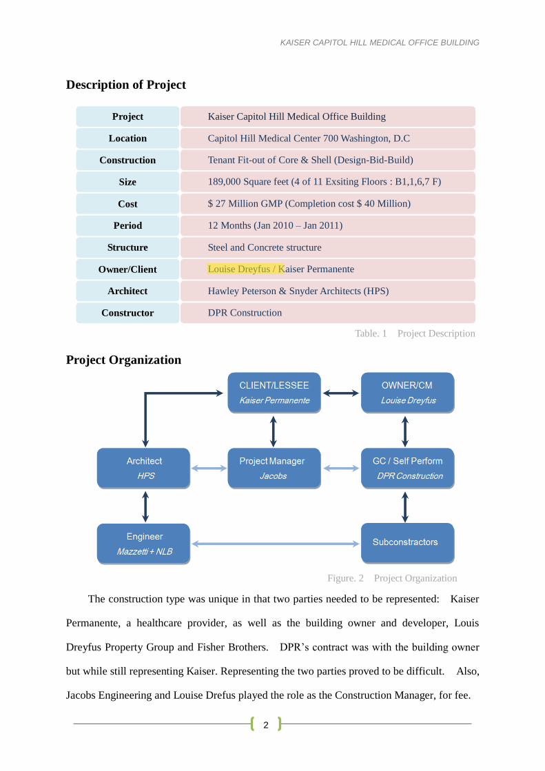
Kaiser Capitol Hill Medical Office Building
Capitol Hill Medical Center 700 Washington, D.C
Tenant Fit-out of Core & Shell (Design-Bid-Build)
189,000 Square feet (4 of 11 Exsiting Floors : B1,1,6,7 F)
$ 27 Million GMP (Completion cost $ 40 Million)
Period
Structure
Owner/Client
Architect
Constructor
12 Months (Jan 2010 – Jan 2011)
Steel and Concrete structure
Louise Dreyfus / Kaiser Permanente
Hawley Peterson & Snyder Architects (HPS)
DPR Construction
Description of Project
Project Organization
The construction type was unique in that two parties needed to be represented: Kaiser
Permanente, a healthcare provider, as well as the building owner and developer, Louis
Dreyfus Property Group and Fisher Brothers. DPR’s contract was with the building owner
but while still representing Kaiser. Representing the two parties proved to be difficult. Also,
Jacobs Engineering and Louise Drefus played the role as the Construction Manager, for fee.
Table. 1 Project Description
Figure. 2 Project Organization

KAISER CAPITOL HILL MEDICAL OFFICE BUILDING
3
Specific Challenges
1. Tight schedule
The schedule for completion called for 1 year, which is
a short amount of time to design, collaborate, fabricate,
and build. The time for BIM coordination, especially,
was not quite enough for DPR.
2. Building structure
Low ceiling heights and height limits in Washington D.C. resulted in low height
stories (1000ft). Since the building was previously an office building, there were low
height stories already in place, and were therefore problematic for hospital equipment
and all MEP systems. Additionally, the building had 11 floors total, with 4 of the
floors being used for the hospital.
3. Coordination.
There were many problems in coordination work. Firstly, it was hard to coordinate
between DPR construction and another construction firm because both construction
companies were going their works in Kaiser Capitol Hill Medical Office Building at the
same time. Thus, DPR construction was difficult to set the schedule for avoiding
overlapping with the other construction going on. Secondly, the collaboration with an
architect and an engineer was another problem. That is because the architect was in
California and the engineer was in Tennessee and DPR was in Washington. Thus, it
was not easy to set the meetings for project.
4. Budget.
The budget for the project was $27 million but ended up at $40 million. The main
reason for this budget increase is the low quality of the architectural/mechanical designs.
Therefore, during constructing the building, there were a number of design changes.
Actually, there were 60 bulletin changes.
Figure. 3
Schedule Timer in DPR office
KAISER CAPITOL HILL MEDICAL OFFICE BUILDING
4
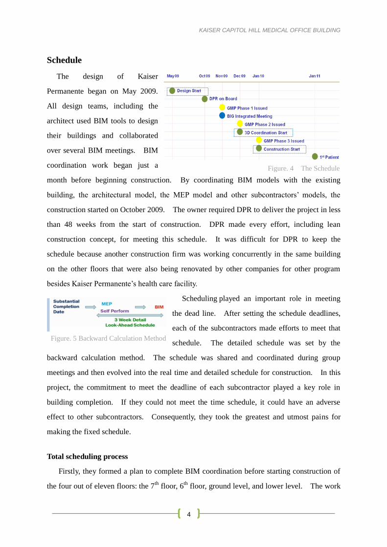
Figure. 5 Backward Calculation Method
Schedule
The design of Kaiser
Permanente began on May 2009.
All design teams, including the
architect used BIM tools to design
their buildings and collaborated
over several BIM meetings. BIM
coordination work began just a
month before beginning construction. By coordinating BIM models with the existing
building, the architectural model, the MEP model and other subcontractors’ models, the
construction started on October 2009. The owner required DPR to deliver the project in less
than 48 weeks from the start of construction. DPR made every effort, including lean
construction concept, for meeting this schedule. It was difficult for DPR to keep the
schedule because another construction firm was working concurrently in the same building
on the other floors that were also being renovated by other companies for other program
besides Kaiser Permanente’s health care facility.
Scheduling played an important role in meeting
the dead line. After setting the schedule deadlines,
each of the subcontractors made efforts to meet that
schedule. The detailed schedule was set by the
backward calculation method. The schedule was shared and coordinated during group
meetings and then evolved into the real time and detailed schedule for construction. In this
project, the commitment to meet the deadline of each subcontractor played a key role in
building completion. If they could not meet the time schedule, it could have an adverse
effect to other subcontractors. Consequently, they took the greatest and utmost pains for
making the fixed schedule.
Total scheduling process
Firstly, they formed a plan to complete BIM coordination before starting construction of
the four out of eleven floors: the 7th
floor, 6th
floor, ground level, and lower level. The work
Figure. 4 The Schedule

KAISER CAPITOL HILL MEDICAL OFFICE BUILDING
5
went from one floor to next after each BIM team finished the corresponding BIM
coordination. However, they recognized that the coordination work took more time than
expected and could have resulted in the delay of starting the construction.
Figure. 6 Schedule Board Figure. 7 Initial BIM Execution Schedule – Last Planner Scheduling
For solving the problem, they decided to operate two BIM teams for BIM coordination.
In addition, they divided the 4 specific sections for reducing time per each coordination works
instead of work for each floor, which enabled them to enter the construction right after
finishing the coordination for each section. The change in BIM coordination work helped to
complete construction quickly.
Figure. 8 Smaller Sections
Figure. 9 Actual BIM Execution Schedule – Last Planner Scheduling
BIM and Interoperability
3D modeling used by DPR was crucial in the design
process and in modeling the complex MEP design. The
Kaiser Capitol Hill Medical Office Building proved that
use of BIM applications was invaluable in completing the
project. This renovation project required the as-built 3D
S #2 S #1
S #4 S #3
Figure. 10 3D Rendering
KAISER CAPITOL HILL MEDICAL OFFICE BUILDING
6
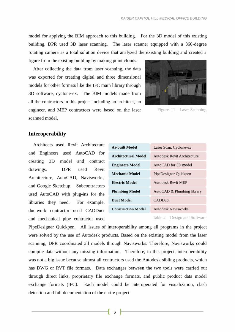
Figure. 11 Laser Scanning
Autodesk Revit Architecture
Engineers Model
AutoCAD for 3D model
Mechanic Model
PipeDesigner Quickpen
Electric Model
Autodesk Revit MEP
Architectural Model
Laser Scan, Cyclone-ex As-built Model
AutoCAD & Plumbing library Plumbing Model
CADDuct
Construction Model
Autodesk Navisworks
Duct Model
Table 2 Design and Software
model for applying the BIM approach to this building. For the 3D model of this existing
building, DPR used 3D laser scanning. The laser scanner equipped with a 360-degree
rotating camera as a total solution device that analyzed the existing building and created a
figure from the existing building by making point clouds.
After collecting the data from laser scanning, the data
was exported for creating digital and three dimensional
models for other formats like the IFC main library through
3D software, cyclone-ex. The BIM models made from
all the contractors in this project including an architect, an
engineer, and MEP contractors were based on the laser
scanned model.
Interoperability
Architects used Revit Architecture
and Engineers used AutoCAD for
creating 3D model and contract
drawings. DPR used Revit
Architecture, AutoCAD, Navisworks,
and Google Sketchup. Subcontractors
used AutoCAD with plug-ins for the
libraries they need. For example,
ductwork contractor used CADDuct
and mechanical pipe contractor used
PipeDesigner Quickpen. All issues of interoperability among all programs in the project
were solved by the use of Autodesk products. Based on the existing model from the laser
scanning, DPR coordinated all models through Navisworks. Therefore, Navisworks could
compile data without any missing information. Therefore, in this project, interoperability
was not a big issue because almost all contractors used the Autodesk sibling products, which
has DWG or RVT file formats. Data exchanges between the two tools were carried out
through direct links, proprietary file exchange formats, and public product data model
exchange formats (IFC). Each model could be interoperated for visualization, clash
detection and full documentation of the entire project.
KAISER CAPITOL HILL MEDICAL OFFICE BUILDING
7
The interesting point in the above chart was a plumbing model made by AutoCAD and
plumbing library. They could not use Revit MEP because the machine making real ducts
only read AutoCAD files. This was perhaps the most problematic interoperability issue;
BIM did not apply to the fabrication component because of the fabricator’s software. This
is commonly a current problem of applying BIM to the real work, and there is still much to
be done to improve the architectural environment.
Design Innovation and Construction
Kaiser Permanente was a hospital renovation from an office building with a core and shell,
or with an existing structure and curtain wall. The work scope included concrete,
mechanical, electrical, and plumbing; an entire renovation and interior construction project of
4 of the floors of the building. DPR had utilized BIM models to identify the design concept
and the project scope of work. BIM was also utilized for visualization and enhancing the
design. All of contractors use Autodesk products like Revit and Revit MEP for 3D
modeling, production scheduling, HVAC design, optimization of various mechanical systems,
energy analysis, performance monitoring, quantity extraction, and estimating.
1. Dynamic animation for evaluating MRI package movement paths
DESIGN DILEMMA: Hospital equipment needs - MRI, CT big equipment results in
difficulties in creating an entrance and circulation pathways that result in ease of
movement and flow.
DESIGN SOLUTION: Dynamic Animation
Generally, in the case of a hospital new construction project, a pathway and an entrance
are set for large equipment like MRI or CT. However, because the Kaiser project was
a renovation project from an office to a hospital, it was difficult to plan the equipment’s
pathways. Dynamic animation in this project was used in that there was a movement
point that moved throughout the model to find how many clash detections occurred.
The path with the fewest clashes was found and once clash detection was performed
and adjustments made, the walls were then constructed after first moving the equipment
or they were built by using precast concrete method. This method was really effective
to show the pathways and to find the best one among several alternative pathways.

KAISER CAPITOL HILL MEDICAL OFFICE BUILDING
8
Clash Detection
MRI
Clash Detection
MRI
Figure. 12 Dynamic Animation for MRI Package Path
2. Pharmacy area virtual mockup
DESIGN DILEMMA: Nurses wanted to confirm that the pharmacy facility and
movement through the facility would assist the ease in flow throughout their workdays.
DESIGN SOLUTION: Virtual Mockup
Figure. 13 Pharmacy area virtual mockup
KAISER CAPITOL HILL MEDICAL OFFICE BUILDING
9
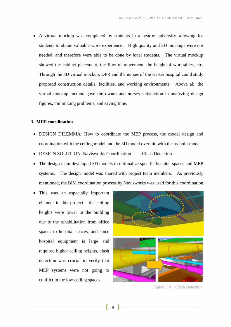
Figure. 14 Clash Detection
A virtual mockup was completed by students in a nearby university, allowing for
students to obtain valuable work experience. High quality and 3D mockups were not
needed, and therefore were able to be done by local students. The virtual mockup
showed the cabinet placement, the flow of movement, the height of worktables, etc.
Through the 3D virtual mockup, DPR and the nurses of the Kaiser hospital could study
proposed construction details, facilities, and working environments. Above all, the
virtual mockup method gave the owner and nurses satisfaction in analyzing design
figures, minimizing problems, and saving time.
3. MEP coordination
DESIGN DILEMMA: How to coordinate the MEP process, the model design and
coordination with the ceiling model and the 3D model overlaid with the as-built model.
DESIGN SOLUTION: Navisworks Coordination - Clash Detection
The design team developed 3D models to rationalize specific hospital spaces and MEP
systems. The design model was shared with project team members. As previously
mentioned, the BIM coordination process by Navisworks was used for this coordination.
This was an especially important
element in this project - the ceiling
heights were lower in the building
due to the rehabilitation from office
spaces to hospital spaces, and since
hospital equipment is large and
required higher ceiling heights, clash
detection was crucial to verify that
MEP systems were not going to
conflict in the low ceiling spaces.

KAISER CAPITOL HILL MEDICAL OFFICE BUILDING
10
Figure. 17 Lean Construction Meeting
Figure. 15 MEP Coordination & Real Construction
Figure. 16 MEP Coordination
4. BIM + Lean construction
DESIGN DILEMMA: Meeting the construction schedule with less waste and less time.
DESIGN SOLUTION: Lean Construction Production Management
Using LEAN construction techniques are used to
maximize overall production value, reduce waste,
and maintain the highest quality. For the LEAN
construction management, the project team
members including the owner, architect, DPR and
subcontractors, worked together to plan the

KAISER CAPITOL HILL MEDICAL OFFICE BUILDING
11
delivery process in conjunction with the facility. The architect, Pritzker award winner
Kevin Roche, used Revit but the architect was located in California and the engineer,
Jonghoon Kim with DPR, was located in Tennessee, making it difficult to coordinate
meetings. However, because of the Big Room Concept (discussed below),
coordination and model updates became possible to promote a more fluid transition and
more reliable work flows between the various trades involved. Every step of the
construction delivery process was broken down. Potential time and space conflicts
and sequencing issues cold be more easily understood through this collaboration
process. It was the pairing of the virtual building technology (3D and 4D models and
computer-aided design drawings) along with a LEAN approach that produced the most
efficient installation of MEP systems.
5. BIG room
DESIGN DILEMMA: Coordination among designers, contractors, subcontractors,
construction, fabricators, etc.
DESIGN SOLUTION: Big room concept – Smart board
After clash detection was performed, the Big Room Concept was implemented. This
is where all parties were able to conference into the meeting held in an I-Room
(Information Room) in which a SMART Board was used to automatically show updates
in the model and then everyone on the team is able to update all the drawings
accordingly. An I-Room is a room large enough to house the entire team and all the
necessary computers and display screens for everyone to follow the process in detail.
The point of getting everyone together in one place is important. This makes the
designer actually a collaborative team, which is under the conducting of the architect.
Figure. 18 BIG Room Coordination
KAISER CAPITOL HILL MEDICAL OFFICE BUILDING
12
3C’s (Collaboration & Coordination & Communication)
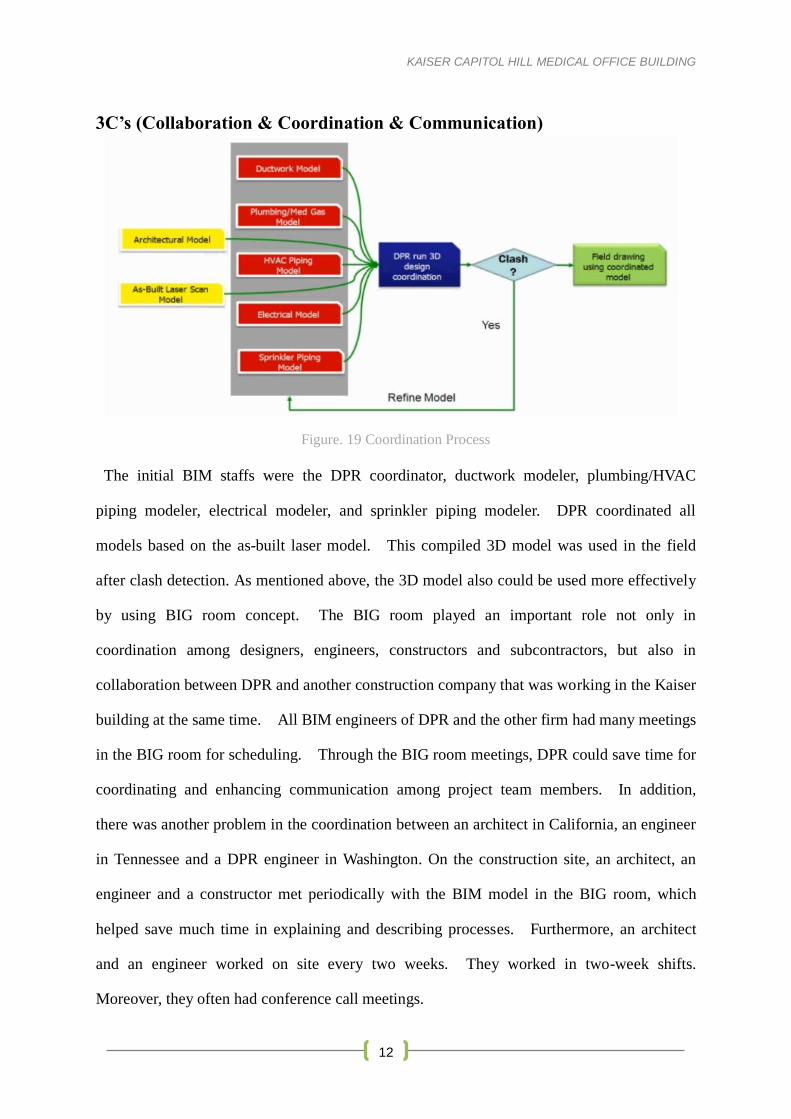
Figure. 19 Coordination Process
The initial BIM staffs were the DPR coordinator, ductwork modeler, plumbing/HVAC
piping modeler, electrical modeler, and sprinkler piping modeler. DPR coordinated all
models based on the as-built laser model. This compiled 3D model was used in the field
after clash detection. As mentioned above, the 3D model also could be used more effectively
by using BIG room concept. The BIG room played an important role not only in
coordination among designers, engineers, constructors and subcontractors, but also in
collaboration between DPR and another construction company that was working in the Kaiser
building at the same time. All BIM engineers of DPR and the other firm had many meetings
in the BIG room for scheduling. Through the BIG room meetings, DPR could save time for
coordinating and enhancing communication among project team members. In addition,
there was another problem in the coordination between an architect in California, an engineer
in Tennessee and a DPR engineer in Washington. On the construction site, an architect, an
engineer and a constructor met periodically with the BIM model in the BIG room, which
helped save much time in explaining and describing processes. Furthermore, an architect
and an engineer worked on site every two weeks. They worked in two-week shifts.
Moreover, they often had conference call meetings.

KAISER CAPITOL HILL MEDICAL OFFICE BUILDING
13
Figure. 20 BIM & Real Work
BIM Benefits Realized
The BIM tools and the coordinated 3D model played a
pivotal role in this MOB project.
Firstly, the use of BIM in pre-design phase was a great
help in the designing and coordination of the hospital’s
mechanical, electric systems and plumbing in low height
stories of the office building. That is, BIM enabled the
project team members to identify the possible problems and
understand the whole project easily, which resulted in successful completion of the project.
Secondly, the use of the same 3D model provided modelers and designers on site with the
opportunities for collaboration and coordination. After MEP coordination, DPR performed
the clash detection, as previously mentioned, with Navisworks, a coordination program
created by Autodesk. The changes made from each subcontractor were updated throughout
those databases so that the changes of each contractor were coordinated quickly. That is,
BIM approach enabled workers to explore and modify changes of the building at any time
without re-coordination of the tasks. Thus, MEP coordination enabled DPR to minimize
coordination time and facilitate manual checking. Also, sharing the Revit model allowed
project members to work together with one model through all phases of the project. Therefore,
the construction on site could go on quickly. The 3D BIM model was a bridge among all
project members (including the other construction firm working at the same time) for
collaboration, coordination and communication.
Thirdly, the BIM tool supports other tools’ application like the dynamic animation, the
virtual mockup, the BIG room concept and the Lean construction. BIM model has the
multi-functions, which allows the project members to see and estimate the project from
various angles through various methods related to BIM model. Also, these functions make a
great contribution in improving the project quality, saving cost, reducing the schedule and
satisfying an owner.
Fourthly, the BIM approach improved the documentation process and was helpful
throughout all administration phases. The 3D database also provided feedback for use in
cost estimating and information was exported to excel and costs were applied to generate cost
estimate.
Lastly, DPR could provide easily and quickly the owner with site utilization and
renovation process, which lead to communicate better with owner and represent the intent of
the owner. BIM in this project enabled workers to deliver better work faster.
Visualizations and mockup test through BIM model requires less time and effort by workers,

KAISER CAPITOL HILL MEDICAL OFFICE BUILDING
14
so the project could proceed ahead faster. Moreover, DPR use BIM model for quantification
of the building and value engineering. This model would be reused for similar project later
in estimating and planning. Also, the BIM model allowed design teams and constructors to
get more work done with fewer people. BIM resulted in less miscommunication and errors.
These benefits resulted in reducing the cost of changes and coordination in administration
process. Furthermore, BIM was used for budgeting and cost estimating. The cost
information and changes could be updated easier.
Figure. 21 BIM Coordination Model
The BIM application’s return on value achieved for the project
DPR was interested in knowing what the return would be on the value achieved for the
project divided by value expended in effort. However, JongHoon Kim, the senior BIM
engineer at DPR, said that it is difficult to evaluate the quantitative analysis. He thought the
benefits of using BIM application were that project participants and owner were entirely
favorable to how BIM improved the quality. The owner was so pleased with the outcome
that Kaiser decided after completion of this project to give their next two projects to DPR.
In addition, KIM could identify other BIM benefits by calculating the real construction
time and cost for coordination comparing them to the conventional method. Also, he could
estimate the BIM advantages through estimating the reduction of RFI’s by using BIM and
how much RFI response time was reduced during sharing BIM model. However, he said
that the results could not be absolutely evaluated.
Lastly, the cost reduction is subjective judgment, so it is difficult to calculate the accurate
KAISER CAPITOL HILL MEDICAL OFFICE BUILDING
15
value. Although it is better to have a coordination work effort as quickly as possible, the
quality of design can be low. Another reason that BIM cannot be a part of the process any
earlier is that early coordination can cause the delay of subcontractor selection.
Conclusion and Lessons Learned
The use of BIM software in the Kaiser Permanente Capitol Hill Medical Center project
was central to the designing, planning, coordinating, organizing, and constructing processes.
It allowed for important procedures such as clash detection, which is essential for all
mechanical systems but especially important when planning for large hospital equipment.
Additionally, the coordination and collaboration between members of the design and
construction team was made possible through the BIM application and the use of same BIM
model. In the Kaiser project, there were few problems with BIM interoperability because
the project members used tools having similar file format. We thought that it is necessary to
plan which BIM applications and which file formats would be interoperable before laying out
the project in the beginning.
This case study did prove several problems when applying BIM to real work. Firstly,
although it is better to have a coordination work as quickly as possible, BIM design and
coordination takes a lot of time. The designs can be of low quality because BIM engineers
may not have enough time to work. The results in many design changes and consequently
increase costs and the delays. Secondly, there were problems that the plumbing contractor
could not prevent while using AutoCAD instead of using 3D Revit because of fabricator’s
software requirements. Another problem was that the architect and other subcontractors still
had low-quality designs, which resulted in a number of design changes and cost increases.
In light of the current situation, we thought that it is necessary to improve the construction
environment and invest in the equipment for BIM application to make an easier transition in
to the use of BIM.
In this project, DPR performed all the metal stud framing, the drywall and acoustic ceilings,
the doors, the frams, and the hardware. DPR reported that next time they would like to use
BIM for drywall framing design, fabrication, quantity take-off, and continue with
coordination of MEP systems. In addition, JongHoon Kim who is a senior BIM engineer at
DPR said, “If we did not use BIM in this project, the project could not been completed on
time. Rather, without BIM, we might not even imagine the execution of project that is a
renovation from an office building to a hospital. If the project can be executed without BIM,
the construction cost would be increased significantly.” BIM allowed DPR to make the
impossible possible.

KAISER CAPITOL HILL MEDICAL OFFICE BUILDING
16
References
Eastman, CM, Teicholz, P, Sacks, R and Liston, K:2008, BIM Handbook: A Guide to
Building Information Modeling for Owners, Managers, Designers, Engineers and
Contractors, John Wiley & Sons, Inc., New Jersey
Kaiser Permanente, Opens New Medical Center on Capitol Hill, Jan. 2011,
http://xnet.kp.org/newscenter/pressreleases/mas/2011/012411capitolhillmc.html
DPR, Kaiser Permanente Station Place 3 Medical Office Building,
http://www.dpr.com/projects/mid-atlantic/detail.cfm?ProjectID=523
Digital Building Lab at Georgia Tech, http://bim.arch.gatech.edu/content_view.asp?id=528
DPR Contact : Jonghoon Kim PhD
| DPR Construction, Inc.
| Mobile: 650-714-3467
| eFax: 703-995-0816