k3vl - kawasaki precision machinery
TRANSCRIPT

Data SheetP-1002/04.11Model K3VL Page 1.
Sizes 45, 80, 112,140 and 200Up to 203 kWand 320bar
Features◊ SAE and ISO mount.◊ Small installation envelope.◊ Through drive.◊ SAE and metric ports.◊ Side and rear porting.◊ Vertical mount capability.◊ Multiple drain ports.◊ CW and CCW rotation.◊ Opposed stroking pistons.◊ Rated pressure 320 bar.◊ Swash plate pillow support.◊ Maximum displacement stop.◊ Servo assist springs.◊ Hydrostatic pillow bearing.◊ Overcentre bleed.◊ Pressure compensation.◊ Integral proportional pressure.
◊ Load sensing.◊ Integral unload.◊ Torque limiter.◊ Rigid construction.◊ Long life roller bearings.◊ Various sealing options.◊ Low pulsation.◊ Proven rotating group.◊ Separate swash plate.◊ Spherical valve plate.◊ Super-finished bores.◊ Solid pistons.
Swash-plateAxial Piston Pump
B Series K3VL
Pumps Industrial Products
Data SheetP-1002/04.11
GB

Data SheetP-1002/04.11Model K3VL Page 2.
Pumps Industrial Products
Data SheetP-1002/04.11Model K3VL Page 3.
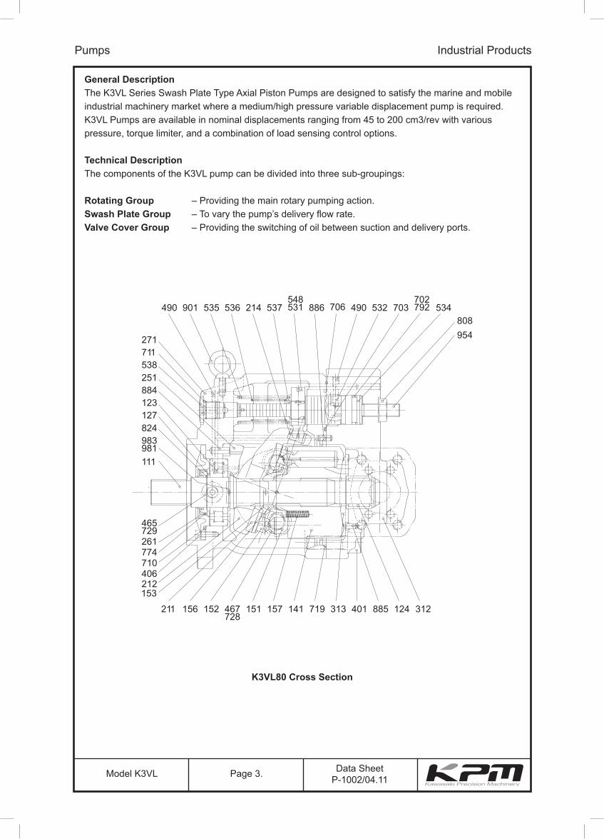
General DescriptionThe K3VL Series Swash Plate Type Axial Piston Pumps are designed to satisfy the marine and mobile industrial machinery market where a medium/high pressure variable displacement pump is required. K3VL Pumps are available in nominal displacements ranging from 45 to 200 cm3/rev with various pressure, torque limiter, and a combination of load sensing control options.
Technical DescriptionThe components of the K3VL pump can be divided into three sub-groupings:
Rotating Group – Providing the main rotary pumping action.Swash Plate Group – To vary the pump’s delivery flow rate.Valve Cover Group – Providing the switching of oil between suction and delivery ports.
Pumps Industrial Products
K3VL80 Cross Section

Data SheetP-1002/04.11Model K3VL Page 4.
Technical Description (continued)
The Rotating Group
The Rotating Group comprises:
(a) Valve plate 313(b) Cylinder block, 141(c) Pistons, 9 x 151 + Shoes, 9 x 152(d) Setting plate, 153(e) Spherical bush, 156(f) Cylinder springs, 9 x 157
The drive shaft is coupled to the cylinder block through a splined section and supported at both of its ends by bearings. The shoe is swaged over the end of the piston forming a ball joint.Additionally the shoe has a hydrostatic pocket to balance the hydraulic thrust developed by the pistonpressure allowing the shoe to lightly slide against the shoe plate.
The subgroup consisting of the pistons and shoes are pressed against the shoe plate by the cylindersprings acting through the setting plate and the spherical bush. The force developed by these cylindersprings also press the cylinder block against the valve plate. Only the K3VL45 units use a singlecentralised spring with individual push pins to provide the shoe and cylinder block hold down force.
Swash Plate GroupThe Swash Plate Group comprises:
(a) Swash plate, 212(b) Shoe plate, 211(c) Swash plate support, 251(d) Tilting bush, 214(e) Tilting pin, 531(f) Servo piston and Springs, 532, 535, 536
The swash plate on the reverse side to the shoe location is a cylindrical form which is a “pillow” supported by the hydrostatic bearing provided by the swash plate support. The tilting bush is inserted into the swash plate and into this is installed the spherical portion of the tilting pin which is coupled to the servo piston.
Any linear movement of the servo piston produced by the regulator pressure applied to either end istranslated through the tilting pin into an angular movement of the swash plate which varies the tilting orswash angle of the pump. A screw adjuster and lock nut is available to adjust the maximum tilting anglecondition. The servo assist springs are provided to ensure good on stroking response particularly at lowoperating pressures.
Pumps Industrial Products

Data SheetP-1002/04.11Model K3VL Page 5.
Technical Description (continued)
Valve Cover Group
The Valve Cover Group comprises:
(a) Valve cover, 312(b) Valve pin, 885
The valve plate with its two “kidney” shaped ports is installed onto the valve cover located by the valve plate pin. These two ports serve to supply and exhaust oil to and from the cylinder block. The oil passage switched by the valve plate is connected to the externally piped inlet and outlet pressure ports through the valve cover. This valve plate is spherical in form for all but the smallest 45cc unit.
Pump Operation
When the pump’s drive shaft is driven by a prime mover (Electric motor, Engine etc.), the cylinder blockbeing spline coupled to the shaft will also rotate. If the swash plate has been tilted, the pistons arranged in the cylinder block due to the shoe being retained on the swash plate surface will both rotate with thecylinder block and reciprocate once per revolution. Paying attention to one such piston then it will moveaway from the valve plate for half a rotation (inlet stroke) and move towards the valve plate for thesecond half of rotation (oil delivery stroke). The larger the tilt angle, the longer the piston stroke and thehigher is the pump’s displacement. As the swash plate tilting angle approaches zero so the piston makes no stroke and thereby delivers no oil.
Through Drive Option
By suitable use of adaptors and splined couplings a wide variety of through drive mounting capabilities are available. The formation of these kits and their relevant part numbers will be found in the installationsection.
Pumps Industrial Products

Data SheetP-1002/04.11Model K3VL Page 6.
Technical Data
For applications outside the following parameters, please consult Kawasaki Precision Machinery (UK) Ltd.
Hydraulic Data
Pressure Fluid Mineral oil, polyol ester and water glycol.
Use a high quality, anti-wear, mineral based hydraulic fluid when the pressure exceeds 206 bar. In applications where fire resistant fluids are required consult Kawasaki Precision Machinery (UK) Ltd. Fluid selection
Pumps Industrial Products
VG22VG32VG46VG68VG100
1000
600
200
100
10-20° 0° 20° 40° 60° 80° 100°
15
20
40
6080
allowable temperature range
fluid temperature (°C)
Ideal working range
kine
mat
ic v
isco
sity
(cS
t)

Data SheetP-1002/04.11Model K3VL Page 7.
Technical Data (continued)
Filtration & Contamination Control
Filtration
The most important means to prevent premature damage to the pump and associated equipment and toextend its working life, is to ensure that hydraulic fluid contamination control of the system is workingeffectively.
This begins by ensuring that at the time of installation that all piping, tanks etc. are rigorously cleaned in a sanitary way. Flushing should be provided using an off line filtration system and after flushing the filter elements should be replaced.
A full flow return line filter of 10 micron nominal should be utilised to prevent contaminant ingress from the external environment, a 5 to 10 micron filter within the tank’s breather is also recommended.
Suggested Acceptable Contamination Level
The relationship between contamination level and pump life is very difficult to predict as it depends on the type and nature of the contaminant present in the system. Sand or Silica in particular, due to its abrasive nature, does significantly reduce the expected life of a pump. Based on the precondition that there is no significant presence of Silica type substances then a minimum Cleanliness level of -/18/15 ISO 4406 or SAE AS 4059E Table 1 Class 9 (NAS 1638 Class 9 ).
Working Fluid Types
Anti-Wear Type Hydraulic fluid
It is generally recommended to use an anti-wear hydraulic fluid like mineral oil when the operating pressure exceeds 206 bar.
Fire-resistant Fluids
Some kind of fire-resistant fluids require special materials for seals, paint and metal finishing. Pleaseconsult Kawasaki Precision Machinery (UK) Limited and provide details of the particular fluid specification and the working conditions so that any special requirements can be ascertained.
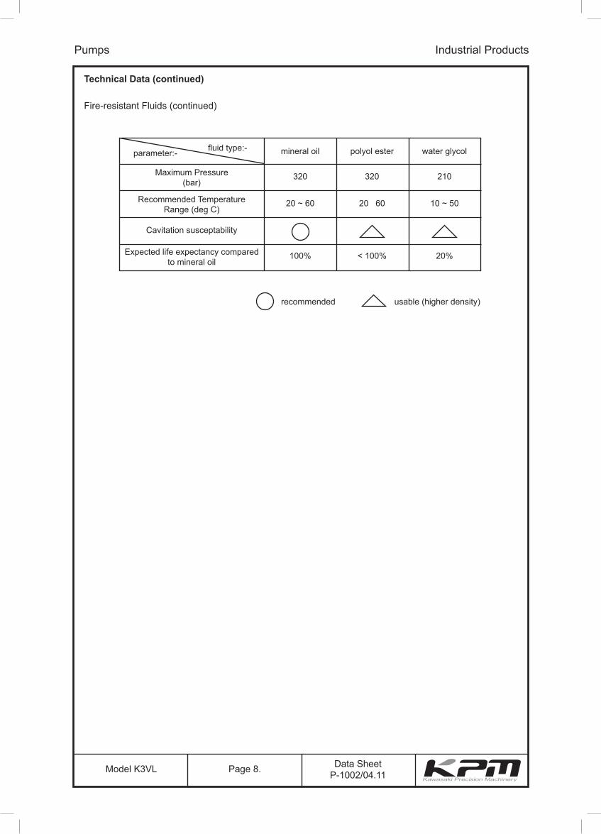
In general, fire-resistant fluids have a low viscosity index and their viscosity also changes significantly with operating temperature and service life. For this reason, the circuit should be provided with an adequately sized cooler or forced cooling so that temperatures can be stabilised. Due to the inherent water content of some of these fluids the minimum allowable suction pressure will be higher than that of an equivalent mineral oil and so needs to be fully evaluated by Kawasaki Precision Machinery (UK) Limited. The following table provides an overview of the precautions and characteristicsthat can be expected with these types of fluids.
Pumps Industrial Products
Data SheetP-1002/04.11Model K3VL Page 8.
Technical Data (continued)
Fire-resistant Fluids (continued)
Pumps Industrial Products
Maximum Pressure(bar)
320 320 210
mineral oilfluid type:- polyol ester water glycol parameter:-
Recommended TemperatureRange (deg C)
20 ~ 60 20 60 10 ~ 50
Expected life expectancy comparedto mineral oil
100% < 100% 20%
Cavitation susceptability
recommended usable (higher density)
Data SheetP-1002/04.11Model K3VL Page 9.
Technical Data (continued)
Pump Start Up Precautions
Pump Case Filling
Be sure to fill the pump casing with oil through the drain port, filling only the suction line with oil is totally in sufficient. The pump contains bearings and high-speed sliding parts including pistons with shoes and spherical bushes that need to be continuously lubricated. Part seizure or total premature failure will occur very quickly if this procedure is not rigidly followed.
Piping & Circuit Checking
Check to see that the piping and full hydraulic circuit is completed and that any gate valves etc. are open.
Direction of Rotation
Check to ensure that direction of rotation is correct and that the inlet and delivery lines are connected correctly.
Start Up
Jog start the motor and check once more for correct rotation. Run the pump unloaded for a period to ensure that all residual air within the system is released. Check for external leakage, abnormal noise and vibrations.
Case Drain Pressure
Please ensure, that the maximum steady state drain line pressure at the pump casing does not exceed 1 bar. (Maximum peak pressure 4 bar). A suitable drain line hose must be selected and return directly back to the tank and terminate below the oil level.
Long Term Out of Usage
It is undesirable to leave the pump out of use for a long period e.g. a year or more. In such a situation it is recommended that the pump is run for a short period on a more frequent basis even if it is just unloaded. With regard to a pump held in storage then rotating the shaft on a frequent basis is sufficient. If the pump is left out for more than the suggested time it will require a service inspection.
Pumps Industrial Products

Page 10.Model K3VL Data SheetP-1002/04.11
Pumps
Technical Data (continued)
SpecificationsThe following table indicates all of the specifications for the complete K3VLpump range from 45-200cc.More detailed efficiency curves and other related information will be found in a later section.
#1 Maximum allowable shaft torques are based on achieving an infinite life for a coupling assembly that is lubricated and completely clamped and utilises the full spline/key length as engagement. The following points therefore need to be fully considered:-
(i) Lubrication of shaft couplings should be in accordance with the coupling manufacturers instructions. (ii) The maximum allowable input shaft torque is based on ensuring an infinite life condition by limiting the resultant combined shaft bending and torsional stress.(iii) This allowable input shaft torque can be further increased dependant on the resultant surface stress at the spline interface which is highly dependant on coupling selection and the provision of adequate spline lubrication. If you have an application that requires higher input torque please consult Kawasaki.#2 Allowable through drive torques are based on the achieving an infinite life for a fully lubricated coupling and full spline engagement with a mineral oil based anti-wear hydraulic fluid.
pump model 45 80 112 140 200capacity cc/rev 45 80 112 140 200
pressure ratingsrated bar 320
peak bar 350
speed ratingsself prime rpm 2,700 2,400 2,200 2,100 1,900
max. boosted rpm 3,250 3,000 2,700 2,500 2,200
minimum operating speed rpm 600
case drain pressure
max. continuous bar 1
peak bar 4
weight kg 25 35 65 65 95
case fill capacity L 0.6 0.8 1.5 1.5 2
maximum allowable input torque #1 (basic coupling arrangement) Nm 140 225 225 225 400 400 400 400 765 980 980 980 400 765 980 980 980 980 980 1800
mounting flangetype SAE B SAE B-B ISO100 SAE C ISO125 SAE D ISO180 SAE D ISO180 SAE E
bolts 2 2 2 4 2 4 4
input shafttype SAE B-B ISO 25mm SAE C ISO 32mm SAE C SAE C-C SAE D ISO 45mm SAE C SAE C-C SAE D ISO 45mm SAE D SAE F
form Spline Spline Key Key Spline Key Key Spline Spline Spline Key Key Spline Spline Spline Key Key Spline Key Spline
allowable through drive
torque #2
SAE “A”
Nm
123
SAE “B” 290 340
SAE “B-B” 290 400 550
SAE "C" / "C4" 400 700 990
SAE “C-C” 700 990
SAE “D” 700 990
SAE “E” 990
temperature range oC -20 to +95
viscosity range cSt 10 to 1,000
maximum allowable contamination level 20 / 18 / 15 ISO/DIS 4406 or SAE AS 4059E Table 1 Class 9 (NAS1638 Class 9)

Industrial Products
pump model 45 80 112 140 200capacity cc/rev 45 80 112 140 200
pressure ratingsrated bar 320
peak bar 350
speed ratingsself prime rpm 2,700 2,400 2,200 2,100 1,900
max. boosted rpm 3,250 3,000 2,700 2,500 2,200
minimum operating speed rpm 600
case drain pressure
max. continuous bar 1
peak bar 4
weight kg 25 35 65 65 95
case fill capacity L 0.6 0.8 1.5 1.5 2
maximum allowable input torque #1 (basic coupling arrangement) Nm 140 225 225 225 400 400 400 400 765 980 980 980 400 765 980 980 980 980 980 1800
mounting flangetype SAE B SAE B-B ISO100 SAE C ISO125 SAE D ISO180 SAE D ISO180 SAE E
bolts 2 2 2 4 2 4 4
input shafttype SAE B-B ISO 25mm SAE C ISO 32mm SAE C SAE C-C SAE D ISO 45mm SAE C SAE C-C SAE D ISO 45mm SAE D SAE F
form Spline Spline Key Key Spline Key Key Spline Spline Spline Key Key Spline Spline Spline Key Key Spline Key Spline
allowable through drive
torque #2
SAE “A”
Nm
123
SAE “B” 290 340
SAE “B-B” 290 400 550
SAE "C" / "C4" 400 700 990
SAE “C-C” 700 990
SAE “D” 700 990
SAE “E” 990
temperature range oC -20 to +95
viscosity range cSt 10 to 1,000
maximum allowable contamination level 20 / 18 / 15 ISO/DIS 4406 or SAE AS 4059E Table 1 Class 9 (NAS1638 Class 9)

Data SheetP-1002/04.11Model K3VL Page 12.
Technical Data (continued)
Specifications
Notes: Rated Pressure Pressure at which life and durability will not be affected. Peak Pressure The instant allowable surge pressure as defined by BS ISO 2944:2000. Life and durability however will be shortened. Maximum Self Priming Speed Values are valid for an absolute suction pressure of 1 bar. If the flow is reduced and the inlet pressure is increased the speed may also be increased. Maximum Boosted Speed Values stated are the absolute maximum permitted speed for which an increased inlet pressure will be required. Weight Approximate dry weights, dependant on exact pump type.
Hydraulic Fluid Mineral anti wear hydraulic fluid – for other fluid types please consult KPM. Viscosity Range If viscosity is in range 200 to 1,000 cSt, then warming up is necessary before commencing full scale running.
Pumps Industrial Products
Data SheetP-1002/04.11Model K3VL Page 13.
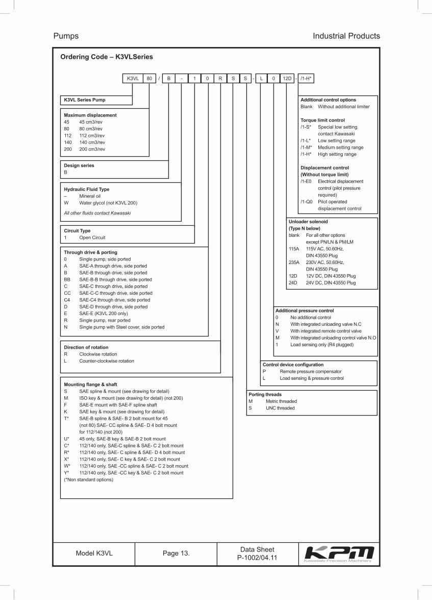
Ordering Code – K3VLSeries
Pumps Industrial Products
K3VL 80 B - 1 0 R S S L 0 12D /1-H*
K3VL Series Pump
Maximum displacement45 45 cm3/rev80 80 cm3/rev112 112 cm3/rev140 140 cm3/rev200 200 cm3/rev
Design seriesB
Hydraulic Fluid Type– Mineral oilW Water glycol (not K3VL 200)
All other fluids contact Kawasaki
Circuit Type1 Open Circuit
Through drive & porting0 Single pump, side portedA SAE-A through drive, side portedB SAE-B through drive, side portedBB SAE-B-B through drive, side portedC SAE-C through drive, side portedCC SAE-C-C through drive, side ported C4 SAE-C4 through drive, side ported D SAE-D through drive, side portedE SAE-E (K3VL 200 only)R Single pump, rear portedN Single pump with Steel cover, side ported
Direction of rotationR Clockwise rotationL Counter-clockwise rotation
Mounting flange & shaftS SAE spline & mount (see drawing for detail)M ISO key & mount (see drawing for detail) (not 200)F SAE-E mount with SAE-F spline shaftK SAE key & mount (see drawing for detail)T* SAE-B spline & SAE- B 2 bolt mount for 45 (not 80) SAE- CC spline & SAE- D 4 bolt mount for 112/140 (not 200)U* 45 only, SAE-B key & SAE-B 2 bolt mountC* 112/140 only, SAE-C spline & SAE- C 2 bolt mountR* 112/140 only, SAE- C spline & SAE- D 4 bolt mountX* 112/140 only, SAE- C key & SAE- C 2 bolt mountW* 112/140 only, SAE -CC spline & SAE- C 2 bolt mountY* 112/140 only, SAE -CC key & SAE- C 2 bolt mount (*Non standard options)
Additional control optionsBlank Without additional limiter
Torque limit control/1-S* Special low setting contact Kawasaki/1-L* Low setting range/1-M* Medium setting range/1-H* High setting range
Displacement control(Without torque limit)/1-E0 Electrical displacement control (pilot pressure required)/1-Q0 Pilot operated displacement control
Unloader solenoid(Type N below)blank For all other options except PN/LN & PM/LM 115A 115V AC, 50.60Hz, DIN 43550 Plug235A 230V AC, 50.60Hz, DIN 43550 Plug12D 12V DC, DIN 43550 Plug24D 24V DC, DIN 43550 Plug
Additional pressure control0 No additional controlN With integrated unloading valve N.CV With integrated remote control valveM With integrated unloading control valve N.O1 Load sensing only (R4 plugged)
Control device configurationP Remote pressure compensatorL Load sensing & pressure control
Porting threadsM Metric threadedS UNC threaded
/ - -

Data SheetP-1002/04.11Model K3VL Page 14.
Bearing Life
Noise Level
Performance K3VL45
Pumps Industrial Products
1.00 0.75 0.50 0.25
00 50 100 150 200 250 300 350
10
20
30
40
50
60
70
80
90
100
0.00
0.10
0.20
0.30
0.40
0.50
0.60
0.70
0.80
0.90
1.00
607075
8083
86
88
89
90
Ratio of displacement
Delivery Pressure (bar)
Volu
met
ric E
ffici
ency
(%)
Rat
io o
f Dis
plac
emen
t
Pump Efficiency (%)
28 30 32 34 36 38 40 42 44
-0.2 bar
-0.1 bar
0 bar
+0.1 bar
+0.2 bar
2200
2400
2600
2800
3000
3200
Displacement q [cc/rev]
Spe
ed N
(rpm
) InletPressurePs (bar)gauge,
measured at the inlet
port of the pump
Self Priming Capability
1
Bea
ring
Life
L10
[hr]
1000000
1000
1000rpm 1200rpm1500rpm1800rpm
E/M capacity [kW]100
10000
100000
85
80
75
70
65
60
55
50100 150
Delivery pressure Pd [kgf/cm2]
Noi
se L
evel
[db(
A)]
200 250 300 350
1800rpm
1500rpm
q = 45cc/rev
10
500

Data SheetP-1002/04.11Model K3VL Page 15.
Bea
ring
Life
L10
[hr]
1000000
1000
1500rpm
1000rpm
1800rpm
1200rpm
1 10E/M capacity [kW]
100
10000
100000
Bearing Life
Noise Level
Performance K3VL80
Pumps Industrial Products
1.00 0.75 0.50 0.25
00 50 100 150 200 250 300 350
10
20
30
40
50
60
70
80
90
100
0.00
0.10
0.20
0.30
0.40
0.50
0.60
0.70
0.80
0.90
1.00
70
75
80
8385
87
89
91
92
Ratio of displacement
Delivery Pressure Pd [kgf/cm2]
Volu
met
ric E
ffici
ency
(%)
Rat
io o
f Dis
plac
emen
t
Pump Efficiency (%)
Self Priming Capability Ps = +0.3bar
Ps = +0.2bar
Ps = +0.1bar
Ps = 0bar
Ps = -0.1bar
Ps = -0.2bar
3000
2800
2600
2400
2200
200050 55 60 65 70 75 80
Displacement q [cc/rev]
Spe
ed N
[min
-1] Inlet
PressurePs (bar)gauge,
measured at the inlet
port of the pump
85
80
75
70
65
60
55
50150100 200
Delivery pressure Pd [kgf/cm2]
Noi
se L
evel
[db(
A)]
250 300 350
1800rpm
1500rpm
q = 80cc/rev
0 50

Data SheetP-1002/04.11Model K3VL Page 16.
Performance K3VL112
Pumps Industrial Products
1.00 0.75 0.50 0.25
00 50 100 150 200 250 300 350
10
20
30
40
50
60
70
80
90
100
0.00
0.10
0.20
0.30
0.40
0.50
0.60
0.70
0.80
0.90
1.00
838075
70
8587
89
91
92
Ratio of displacement
Delivery Pressure (bar)
Volu
met
ric E
ffici
ency
(%)
Rat
io o
f Dis
plac
emen
t
Pump Efficiency (%)
70 80 90 100 110
Ps = -0.2bar
Ps = -0.1bar
Ps = 0bar
Ps = +0.1bar
Ps = +0.3bar
Ps = +0.2bar
1800
2000
2200
2400
2600
2800
Displacement q [cc/rev]
Spe
ed N
[min
-1] Inlet
PressurePs (bar)gauge,
measured at the inlet
port of the pump
Bearing Life
Noise Level
Self Priming Capability
1000000
1000
1000rpm1200rpm
1500rpm1800rpm
E/M capacity [kW]100
10000
100000
85
80
75
70
65
60
55
50150100 200
Delivery pressure Pd [kgf/cm2]
Noi
se L
evel
[db(
A)]
250 300 350
1800rpm
1500rpm
q = 112cc/rev
1
0 50
10
Bea
ring
Life
L10
[hr]
Data SheetP-1002/04.11Model K3VL Page 17.
10
0
1
Bea
ring
Life
L10
[hr]
1000000
1000
1000rpm 1200rpm
1500rpm
1800rpm
E/M capacity [kW]100
10000
100000
85
80
75
70
65
60
55
50150100 200
Delivery pressure Pd [kgf/cm2]
Noi
se L
evel
[db(
A)]
250 300 350
1800rpm
1500rpm
q = 140cc/rev
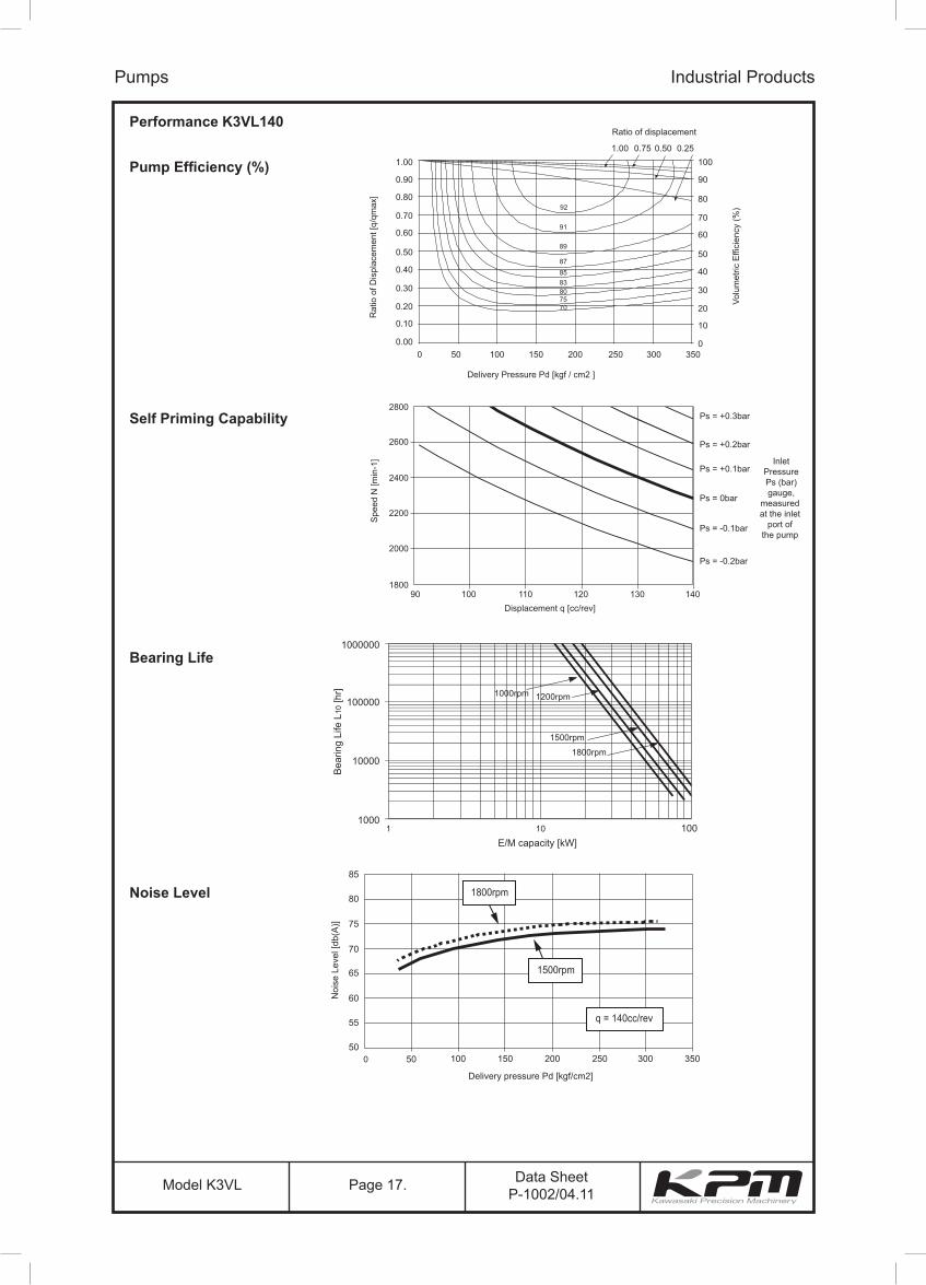
Performance K3VL140
Pumps Industrial Products
1.00 0.75 0.50 0.25
00 50 100 150 200 250 300 350
10
20
30
40
50
60
70
80
90
100
0.00
0.10
0.20
0.30
0.40
0.50
0.60
0.70
0.80
0.90
1.00
91
89
878583807570
92
Ratio of displacement
Delivery Pressure Pd [kgf / cm2 ]
Volu
met
ric E
ffici
ency
(%)
Rat
io o
f Dis
plac
emen
t [q/
qmax
]
Pump Efficiency (%)
Self Priming Capability
Bearing Life
90 100 110 120 130 140
Ps = -0.2bar
Ps = -0.1bar
Ps = 0bar
Ps = +0.1bar
Ps = +0.3bar
Ps = +0.2bar
1800
2000
2200
2400
2600
2800
Displacement q [cc/rev]
Spe
ed N
[min
-1] Inlet
PressurePs (bar)gauge,
measured at the inlet
port of the pump
Noise Level
50

Data SheetP-1002/04.11Model K3VL Page 18.
120 140 160 180 200
Ps = -0.2bar
Ps = -0.1bar
Ps = 0bar
Ps = +0.1bar
Ps = +0.2bar
1700
1600
1800
1900
2000
2100
Displacement q [cc/rev]
Spe
ed N
(min
-1)
85
80
75
70
65
60
55
50150100 200
Delivery pressure Pd [kgf/cm2]
Noi
se L
evel
[db(
A)]
250 300 350
1500rpm
1800rpm
q = 200cc/rev
Bea
ring
Life
L10
[hr]
1000000
100000
10000
1000
1000rpm
1200rpm 1500rpm
1800rpm
10 100 1000E/M capacity [kW]
Performance K3VL200
Pumps Industrial Products
1.00 0.75 0.50 0.25
0 50 100 150 200 250 300 350
100
75
50
25
00.00
0.25
0.50
0.75
1.00
89
87
858380
75
70
91
90
Ratio of displacement
Delivery Pressure (bar)
Volu
met
ric E
ffici
ency
(%)
Rat
io o
f Dis
plac
emen
t
Pump Efficiency (%)
Self Priming Capability
Bearing Life
Noise Level
0 50
2200
InletPressurePs (bar)gauge,
measured at the inlet
port of the pump

Data SheetP-1002/04.11Model K3VL Page 19.
Bearing Life (continued)
Bearing Life Correction Factors for Partial Displacement
Pumps Industrial Products
75%
Displacement %
Bea
ring
life
adju
stm
ent f
acto
r (%
)
50%0%
200%
260%
400%
600%
800%
1000%
1200%
60% 70% 80% 85% 90%
All bearing life curves on the previous pages refer to L10 life at full displacement. The foregoing curve is therefore to be used where duty cycle considerations require one to compute weighted life, which include partial displacement conditions.
For example as shown above if the bearing life at full displacement from the previous graphs was say 50,000 hours, then at the same operating condition with only 75% displacement the bearing life would be 260% of 50,000 hours or 130,000 hours.

Data SheetP-1002/04.11Model K3VL Page 20.
Radial Loading Capacity
No axial shaft loading possible Radial loading is achievable but in specific orientation:-
In addition because of the high bearing capacity of the front bearing, radial shaft loading can be allowed provided that its orientation is such that the front bearing takes the additional load (See diagram below).
Note: In this case bearing life will be reduced.
Pumps Industrial Products
acceptable
not acceptable
Data SheetP-1002/04.11Model K3VL Page 21.
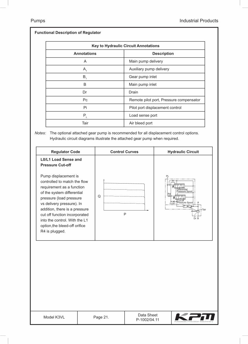
Functional Description of Regulator
Pumps Industrial Products
Key to Hydraulic Circuit Annotations
Annotations
A
A1
B1
B
Dr
Pc
Pi
PL
Tair
Description
Main pump delivery
Auxiliary pump delivery
Gear pump inlet
Main pump inlet
Drain
Remote pilot port, Pressure compensator
Pilot port displacement control
Load sense port
Air bleed port
Notes: The optional attached gear pump is recommended for all displacement control options. Hydraulic circuit diagrams illustrate the attached gear pump when required.
Regulator Code Control Curves Hydraulic Circuit
L0/L1 Load Sense andPressure Cut-off
Pump displacement is controlled to match the flow requirement as a function of the system differential pressure (load pressure vs delivery pressure). In addition, there is a pressure cut off function incorporated into the control. With the L1 option,the bleed-off orifice R4 is plugged.
Q
P
PL
A
Dr
Tair
R1
R4
DifferentialPressure Spool
Cut-offPressure Spool
B
Q
P
PL
A
Dr
Tair
R1
R4
DifferentialPressure Spool
Cut-offPressure Spool
B

Data SheetP-1002/04.11Model K3VL Page 22.
Functional Description of Regulator (continued)
Pumps Industrial Products
Regulator Code Control Curves Hydraulic Circuit
LN Load Sense and Pressure Cut-off with Integrated Unloading Valve (Normally Closed)
An integrated unloading valve is sandwiched between the Load Sense regulator and pump to effectivelyde-stroke the swashplate when an electric signal is provided.
Q
P
Dr B
A
Tair
PL
R3
R1Cut-offPressure Spool
UnloadingSolenoid
Valve
DifferentialPressure Spool
Q
P
Dr B
A
Tair
PL
R3
R1Cut-offPressure Spool
UnloadingSolenoid
Valve
DifferentialPressure Spool
Regulator Code Control Curves Hydraulic Circuit
LM Load Sense and Pressure Cut-off with Integrated Unloading Valve (Normally Open)
An integrated unloading valve is sandwiched between the Load Sense regulator and the pump. An electrical signal must be provided to prevent the Load Sense line from draining.
Q
P
Dr B
A
Tair
PL
R3
R1Cut-offPressure Spool
UnloadingSolenoid
Valve
DifferentialPressure Spool
Q
P
Dr B
A
Tair
PL
R3
R1Cut-offPressure Spool
DifferentialPressure Spool
Regulator Code Control Curves Hydraulic Circuit
LV Load Sense and Pressure Cut-off with Integrated Proportional Relief Valve
An integrated proportional relief valve is sandwiched between the Load Sense regulator and pump to control the maximum pressure setting by varying an electric signal to the valve.A separate amplifier is required.
Q
P
Dr B
A
Tair
PL
R3
R1Cut-offPressure Spool
ProportionalReliefValve
DifferentialPressure Spool
Q
P
Dr B
A
Tair
PL
R3
R1Cut-offPressure Spool
ProportionalReliefValve
DifferentialPressure Spool

Data SheetP-1002/04.11Model K3VL Page 23.
Functional Description of Regulator (continued)
Pumps Industrial Products
Regulator Code Control Curves Hydraulic Circuit
L0/1 Load Sense and Pressure Cut-off with Torque Limiting
L0/L1 control functions aspreviously noted. In response to a rise in delivery pressure the swashplate angle isdecreased, restricting the input torque. This regulator prevents excessive load against the prime mover.The torque limit control module is comprised of two springs that oppose the spool force generated by the system pressure. By turning an outer and inner spring adjustment screw, the appropriate input torque limit can be set.
Q
P
Dr B
A
Tair
PL
R4
R1Cut-offPressure Spool
Torque LimiterSpool
DifferentialPressure Spool
Q
P
Dr B
A
Tair
PL
R4
R1Cut-offPressure Spool
Torque LimiterSpool
DifferentialPressure Spool
Regulator Code Control Curves Hydraulic Circuit
P0 Pressure Cut-off
As system pressure rises to the cut-off setting, the swashplate de-strokes to prevent the system pressure from exceeding the compensator setting. It isimperative that a safety reliefvalve be installed in the system.
Note: By connecting the Pc port to a remote pressure control, variable pump pressure control can be achieved.
Q
P
Dr B
A
Tair
Pc
R2
R1Cut-offPressure Spool
DifferentialPressure Spool
Q
P
Dr B
A
Tair
Pc
R2
R1Cut-offPressure Spool
DifferentialPressure Spool

Data SheetP-1002/04.11Model K3VL Page 24.
Functional Description of Regulator (continued)
Pumps Industrial Products
Regulator Code Control Curves Hydraulic Circuit
PN Pressure Cut-off withIntegrated Unloading Valve(Normally Closed)
An integrated unloading valve is sandwiched between thePressure Cut-off regulator andpump to effectively de-stroke the swashplate when an electric signal is provided.
Q
P
Dr B
A
Tair
Pc
R2
R1Cut-offPressure Spool
SolenoidValve
DifferentialPressure Spool
R3
Regulator Code Control Curves Hydraulic Circuit
PM Pressure Cut-off withIntegrated Unloading Valve(Normally Open)
An integrated unloading valve is sandwiched between the Pressure Cut-off regulator and the pump.
An electrical signal must be provided to prevent the Pc line from draining.
Q
P
Dr B
A
Tair
Pc
R2
R1Cut-offPressure Spool
SolenoidValve
DifferentialPressure Spool
R3
Q
P
Dr B
A
Tair
Pc
R2
R1Cut-offPressure Spool
SolenoidValve
DifferentialPressure Spool
R3
Q
P
Dr B
A
Tair
Pc
R2
R1Cut-offPressure Spool
SolenoidValve
DifferentialPressure Spool
R3

Data SheetP-1002/04.11Model K3VL Page 25.
Functional Description of Regulator (continued)
Pumps Industrial Products
Regulator Code Control Curves Hydraulic Circuit
PV Pressure Cut-off withIntegrated Proportional Relief Valve
An integrated proportional relief valve is sandwiched between the Pressure Cut-off regulator and the pump to control the maximum pressure setting by varying an electric signal to the valve.
A separate amplifier is required.
Q
P
Dr B
A
Tair
Pc
R2
R1Cut-offPressure Spool
ProportionalReliefValve
DifferentialPressure Spool
Q
P
Dr B
A
Tair
Pc
R2
R1Cut-offPressure Spool
ProportionalReliefValve
DifferentialPressure Spool
Regulator Code Control Curves Hydraulic Circuit
P0/1 Pressure Cut-off withTorque Limiting
P0/1 control functions aspreviously noted. In response to a rise in delivery pressure the swashplate angle is reduced, restricting the input torque. This regulator prevents excessive load against the prime mover.
The torque limit control module is comprised of two springs that oppose the spool force generated by the system pressure. By turning an outer and inner spring adjustment screw, the appropriate input torque limit can be set.
Note: By connecting the Pc port to a remote pressure control, variable pump pressure control can be achieved.
Q
P
Outer SpringAdjustment
Delivery Pressure
Pum
p Fl
ow
Outer Plus InnerSpring Adjustment
Dr B
A
Tair
PC
R2
R1
Cut-offPressure Spool
Torque SpoolLimiter
DifferentialPressure Spool
Q
P
Outer SpringAdjustment
Delivery Pressure
Pum
p Fl
ow
Outer Plus InnerSpring Adjustment
Dr B
A
Tair
PC
R2
R1
Cut-offPressure Spool
Torque SpoolLimiter
DifferentialPressure Spool

Data SheetP-1002/04.11Model K3VL Page 26.
Functional Description of Regulator (continued)
Pumps Industrial Products
Regulator Code Control Curves Hydraulic Circuit
/1-E0 Electrical Displacement Control
Varying the input current signal to the pump controller’selectronic proportional pressure reducing valve (PPRV) allows the user to control the pump displacement. As the currentsignal to the PPRV increases,the pump displacementincreases proportionally. Note: An external pressuresupply of 40 bar is required atthe Pi Port (50bar max).
Qmax
Pum
p Fl
ow R
ate
(Q)
Qmin
Input Current (mA) of ProportionalPressure Reading Valve
360 600
CustomerSupplied
Pi
A
BDr B1
A1
Pc
Tair
Regulator Code Control Curves Hydraulic Circuit
/1-Q0 Pilot OperatedDisplacement Control
Varying the input pressuresignal to the Pi port allowsthe user to control the pumpdisplacement. As the pressuresignal to the Pi increases,the pump displacementincreases proportionally.
Qmax
Pum
p Fl
ow R
ate
(Q)
Qmin
Pilot Pressure (bar)
90 28
a
Pi
Pc
A
BDrCustomerSupplied
B1
A1Tair
Qmax
Pum
p Fl
ow R
ate
(Q)
Qmin
Pilot Pressure (bar)
90 28
a
Pi
Pc
A
BDrCustomerSupplied
B1
A1Tair

Data SheetP-1002/04.11Model K3VL Page 27.
Torque Limiter Settings
The following tabulations show the power limitation at various electric motor speeds for a specific pump.When selecting a control setting please ensure that the power limitation of a particularly sized electricmotor to your national standard is not exceeded.
Pumps Industrial Products
K3VL45KW 970 1150 1450 17503.7 S3 S45.5 L3 S1 S3 S47.5 L1 L2 L4 S211 M1 M3 L1 L215 H3 H4 M2 M4
18.5 H2 H4 M222 H3 H430 H13745557590
K3VL80KW 970 1150 1450 17503.75.5 S2 S47.5 L6 S1 S311 L2 L4 L6 S115 M4 L1 L3 L5
18.5 M1 M3 L1 L322 H3 M1 M4 L130 H1 H2 H4 M237 H2 H445 H1 H255 H17590
K3VL112KW 970 1150 1450 17503.75.57.5 S5 S611 S1 S3 S5 S615 L3 L4 S2 S4
18.5 M4 L2 L4 S222 M2 M4 L3 L430 H4 M1 M3 L137 H2 H3 M1 M345 H2 H4 M155 H2 H475 H190
K3VL140KW 970 1150 1450 17503.75.57.511 S2 S415 L6 S1 S3
18.5 L3 L5 S1 S322 L1 L3 L6 S130 M2 M3 L2 L437 H4 M1 M3 L245 H2 H4 M2 M355 H2 H4 M275 H1 H390 H1
K3VL200KW 970 1150 1450 17503.75.57.51115
18.5 S122 L4 S130 L2 L3 L537 M3 L1 L345 M1 M3 L255 H5 M1 M375 H1 H3 H690110132
H1 H4H2
S2L5L3L2M2H6H4H2
S-rating SpringsPlease contact Kawasaki

Data SheetP-1002/04.11Model K3VL Page 28.
Installation
Pump Mounting Options
Drain lineIt is the preferred option to mount the pump with the case drain piping initially rising above the pump before continuing to the tank. Do not connect the drain line to the inlet line.
The uppermost drain port should be used and the drain piping should be equal or larger in size than thedrain port to minimise pressure in the pump case. The pump case pressure should not exceed 1 bar asshown in the illustration below. (Peak pressure should never exceed 4 bar.)
Pumps Industrial Products
Cautions A) Inlet and drain pipes must be immersed by 200mm minimum from the lowest oil level under operating conditions. B) Height from the oil level to the centre of the shaft must be within 1 meter maximum. (consult Kawasaki). C) The oil in the pump case must be refilled when the pump has not been operated for one month or longer.
4 bar(peak)
1 bar(normal)
0.1 secP
200mmminimum
depth
200mmminimum
depth
with
in 1
m
Mus
t be
high
er th
anto
p of
Pum
p C
ase
200mmminimum
depth
Fluid level
Fluid level
Mounting the Pump Above the TankSuction line
4 bar(peak)
1 bar(normal)
0.1 secP
200mmminimum
depth
200mmminimum
depth
with
in 1
m
Mus
t be
high
er th
anto
p of
Pum
p C
ase
200mmminimum
depth
Fluid level
Fluid level
4 bar(peak)
1 bar(normal)
0.1 secP
200mmminimum
depth
200mmminimum
depth
with
in 1
m
Mus
t be
high
er th
anto
p of
Pum
p C
ase
200mmminimum
depth
Fluid level
Fluid level

Data SheetP-1002/04.11Model K3VL Page 29.
Installation (continued)
Mounting the Pump Vertically (shaft up)
Note: Both the Tair and one case drain port must be used.
For applications requiring vertical installation (shaft up) please remove the Tair bleed plug and connectpiping as shown in the illustration below.
When installing the pump in the tank and submerged in the oil, open the drain port and Tair bleed port to provide adequate lubrication to the internal components. See illustration [a].
The oil level in the tank should be higher than the pump-mounting flange as shown in illustration [a]below. If the oil level in the tank is lower than the pump mounting flange then forced lubrication isrequired through the Tair bleed port 1 ~ 2 l/min.
When installing the pump outside the tank run piping for the drain and Tair bleed ports to tank (seeillustration [c]). If the drain or Tair bleed piping rise above the level of oil (see illustration [b]) fill the lineswith oil before operation.motor to your national standard is not exceeded.
Pumps Industrial Products
A check valve with cracking pressure of 0.1 bar should be fitted to the case drain line as shown.
pipe for air bleeding
min. oil level
Tair bleederplug port
drain portpipe for draining
Dr
Tair
TairDr
DrDr
[c][b][a]
check valvecracking pressure
0.1 bar
oiloil

Data SheetP-1002/04.11Model K3VL Page 30.
datums
dial gauge (reading a)δ =a/2 0.025mm
dial gauge (reading b)α=SIN-1 (b/D)
0.2°
δ
D
α
datums
b
Drive Shaft Coupling
Use a flexible coupling to connect the pump shaft to an engine flywheel or electric motor shaft. Alignment should be within 0.05mm TIR as shown in the illustration below.
Do not apply any radial or axial loading to the pump shaft. For applications where radial or side loads exist please contact Kawasaki Precision Machinery (UK) Ltd. for recommendations.
Do not force the coupling on or off the pump shaft. Use the threaded hole in the end of the pump shaft to fix or remove the coupling.
Pumps Industrial Products
For engine drives a split type pinch bolt drive flange and flexible coupling is recommended.
Moment of Inertia and Torsional Stiffness
Moment of InertiaGD2 (kgf.m2)
Torsional Stiffness(N.m/rad)
K3VL45 1.54 x 10⁻² 3.59 x 10⁴
K3VL80 2.92 x 10⁻² 4.83 x 10⁴
K3VL112 8.06 x 10⁻² 9.33 x 10⁴
K3VL140 8.06 x 10⁻² 9.33 x 10⁴
K3VL200 1.83 x 10⁻¹ 1.54 x 10⁵

Data SheetP-1002/04.11Model K3VL Page 31.
Through Drive Limitations (continued)
Through Drive LimitationsApart from predefined maximum throughput limitations, one must also ensure that to prevent a possibleexcessive bending moment occurring that the maximum combined bending moment of the combination is not exceeded as determined in the following expression
Electrical and Pilot Operated Displacement Control (Type E0, Q0)Type E0 - Typical minimum flow setting for the K3VL pump is 0.5-3.0% of the maximum pump delivery. In order for the electronic displacement control to function, a minimum pilot pressure of 40 bar must be supplied to the Pi port on the regulator. A gear pump attached to the rear of the K3VL pump or an external pressure source can be used to provide the required pilot pressure.Type Q0 - In order for the Q0 displacement control to function, a varible pilot pressure between 0 and 40 bar is required.
Proportional Pressure Reducing Valve SpecificationMaximum Pilot Pressure : 50 bar (If higher pressure required contact KPM)Max Flow : 10 l/minHydraulic oil : Mineral oilOil temp range : -20~+90°CViscosity range : 5~500 cstAllowable contamination : NAS grade 10 and belowElectrical specifications,Rated current : 700 mARecommended dither : 80 Hz / 200 mAp-pCoil resistance : 17.5 Ω(at 20°C)Ambient temperature range : -30~+80°CWater resistance : According to JIS D 0203 S2
Pumps Industrial Products
PumpSize4580
112/140200
Maximum PermisableBending Moment (Nm)
137244462930
Adaptor Kits Weight & WidthPumpsize
45
AdaptorKit
WeightKg
Widthmm
SAE “A” 0 0SAE “B” & “BB” 2 20
80SAE “A” 0 0
SAE “B” & “BB” 3 20SAE “C” & “C4” 4 24.5
SAE “A” 0 0SAE “B” & “BB” 3 25
SAE “C”, “CC” & “C4” 5 30SAE “D” 10 43
112& 140
SAE “A” 1 6SAE “B” & “BB” 8 25
SAE “C”, “CC” & “C4” 8 30SAE “D” 10 38SAE “E” 15 38
200
Pump over all length mmFrame size Single pump type N
45 244
80 272
112/140 307.5
200 359
Pump approx weight KgSingle pump type N
Without Torque limitor With Torque limitor
28 30
38 40
69 71
103 105
Pump CofG from mount mmFrame size Single pump type N
45 120
80 130
112/140 150
200 190

Data SheetP-1002/04.11Model K3VL Page 32.
Unit Dimensions (continued)
Electrical Displacement Control
Pumps Industrial Products
G
F
ACB
Pc
ED
Pi
Pi
Pi
Pump Size
Installation Dimensions (mm)
K3VL45 21A
K3VL80K3VL112/140
K3VL200
253857
52B
596461
90C
837880
187D
202244258
157E
172214229
226F
233247257
210G
217231249

Data SheetP-1002/04.11Model K3VL Page 33.
Unit Dimensions (continued)
Pumps Industrial Products
Unloading valve module (Type N,M)
K3VL45
K3VL80
K3VL112/140
K3VL200
A
169
169
202
212
B
155
166
190
205
Proportional pressure module (*V)
K3VL45
K3VL80
K3VL112/140
K3VL200
A
179
179
212
222
B
233
244
280
295
A: Distance between the centre line of the pump and the top of the bolt head for the cut off regulator.B: Distance between the centre line of the pump and top of the solenoid valve.

Data SheetP-1002/04.11Model K3VL Page 34.
Unit Dimensions
K3VL45 Installation
K3VL45 with Cut-Off / Load Sense Control& Torque Limit Module (Clockwise Rotation)
Pumps Industrial Products
See Torque Limit Detail
and Adjustment
See Max. Flow Adjustment DetailAdjustment screw forhorsepower setting
Adjustment screw fordifferential pressure
Adjustment screwfor cut-off pressure
See PortDetails
See PortDetails
119
154
160
218184
14.3
14.3
91
ø38ø25
A
91184
26.2 ±0.2
52.4
±0.
2
1335.7 ±0.2
69.8
±0.
2
7316
6 7070
ø90
14440
40
8080 9989
556.5
PLPC
PLPC
PLPCPLPCPLPC
TairTair
45°
45° Dr
Dr
Dr
Dr
B
A
Dr
Dr
B
B
A
Note:for counter clockwise rotation,the inlet port “B” and thedelivery port “A” are reversed
Data SheetP-1002/04.11Model K3VL Page 35.
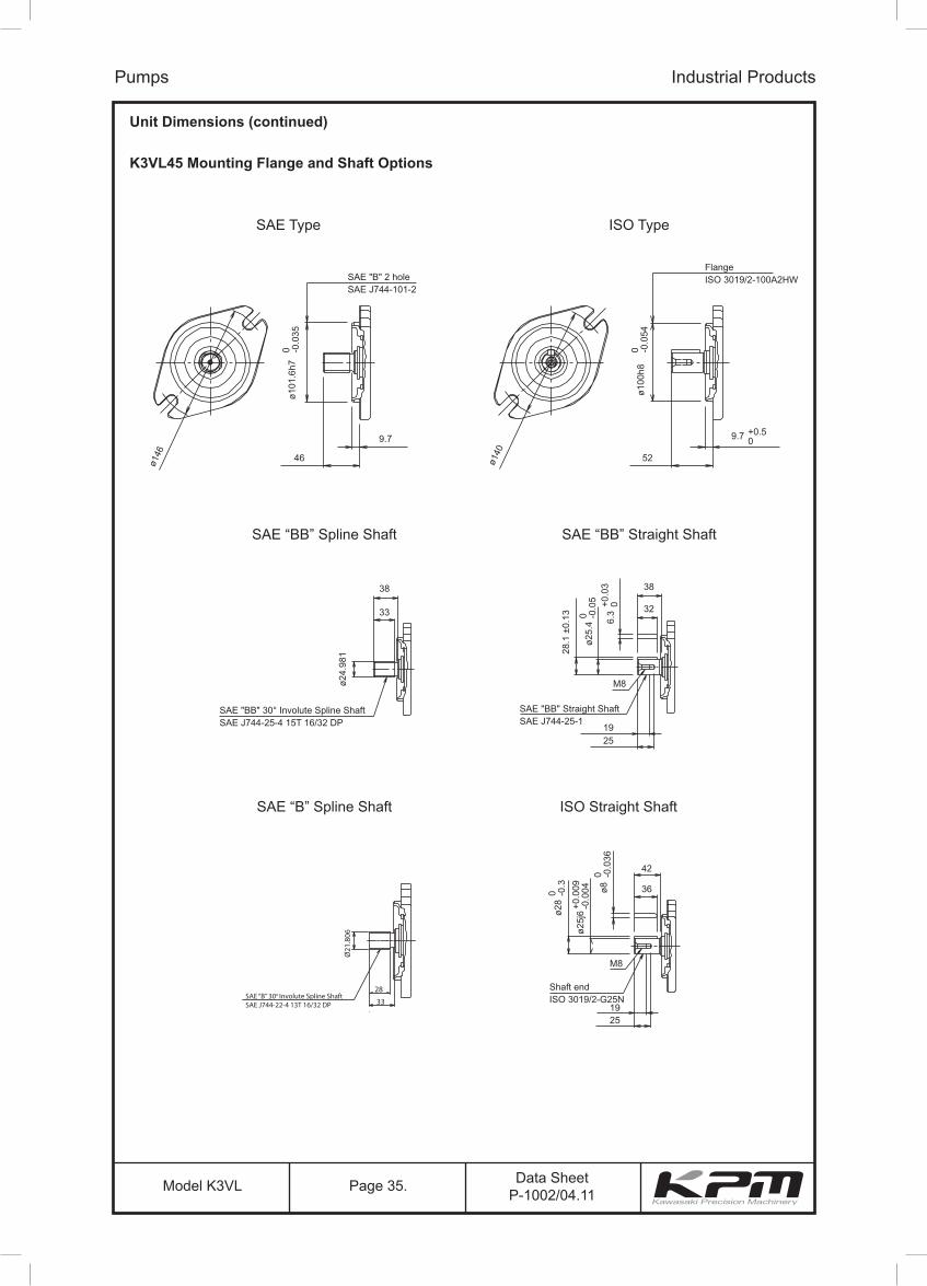
Unit Dimensions (continued)
K3VL45 Mounting Flange and Shaft Options
Pumps Industrial Products
ø146
ø140
SAE "B" 2 holeSAE J744-101-2
SAE "BB" 30° Involute Spline ShaftSAE J744-25-4 15T 16/32 DP
SAE "BB" Straight ShaftSAE J744-25-1
Shaft endISO 3019/2-G25N
FlangeISO 3019/2-100A2HW
9.7
52
38
19
38
32
M8
25
42
36
M8
1925
ø24.
981
33
46
ø101
.6h7
0 -0.0
35
ø100
h80 -0
.054
ø25.
40 -0
.05
6.3
+0.0
30
28.1
±0.
13
9.7 +0.50
ø28
0 -0.3 ø8
0 -0.0
36
ø25j
6+0
.009
-0.0
04
SAE “B” 30o Involute Spline ShaftSAE J744-22-4 13T 16/32 DP
28
33
Ø21
.806
SAE Type ISO Type
SAE “BB” Spline Shaft
SAE “B” Spline Shaft
SAE “BB” Straight Shaft
ISO Straight Shaft
Data SheetP-1002/04.11Model K3VL Page 36.
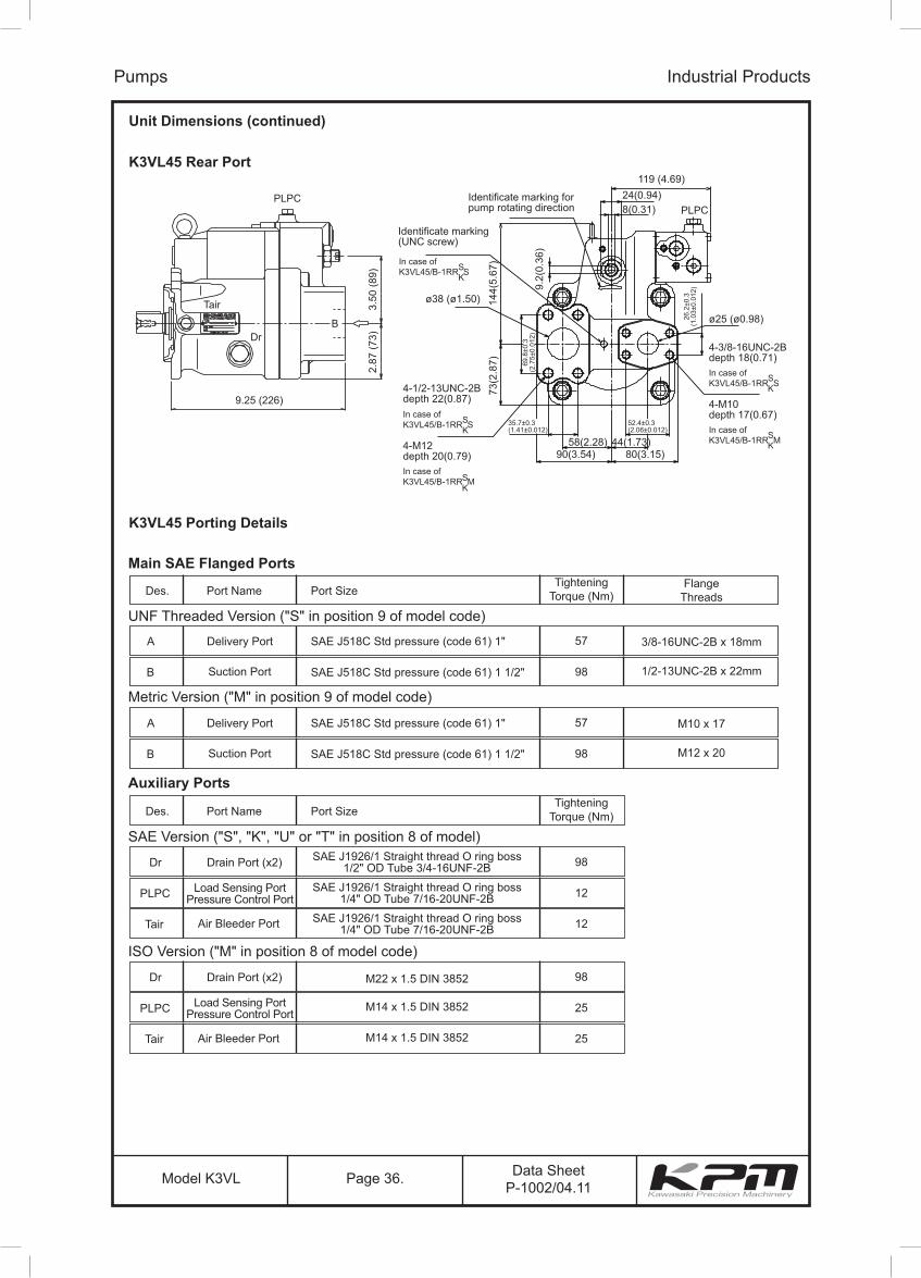
Unit Dimensions (continued)
K3VL45 Rear Port
Pumps Industrial Products
PLPCPLPC
ø25 (ø0.98)
ø38 (ø1.50)
4-3/8-16UNC-2Bdepth 18(0.71)
4-M10depth 17(0.67)
In case ofK3VL45/B-1RR S
In case ofK3VL45/B-1RR M4-M12
depth 20(0.79)
4-1/2-13UNC-2Bdepth 22(0.87)In case ofK3VL45/B-1RR SS
K
In case ofK3VL45/B-1RR SS
K
SK
In case ofK3VL45/B-1RR M
119 (4.69)
Identificate marking forpump rotating direction
Identificate marking(UNC screw)
24(0.94)8(0.31)
80(3.15)90(3.54)58(2.28) 44(1.73)
BDr
Tair
2.87
(73)
73(2
.87)
144(
5.67
)
9.2(
0.36
)
3.50
(89)
9.25 (226)
SK
SK
35.7±0.3(1.41±0.012)
69.8
±0.3
(2.7
5±0.
012)
26.2
±0.3
(1.0
3±0.
012)
52.4±0.3(2.06±0.012)
K3VL45 Porting Details
Main SAE Flanged Ports
UNF Threaded Version ("S" in position 9 of model code)
Des. Port Name Port SizeTightening
Torque (Nm)Flange
Threads
A Delivery Port SAE J518C Std pressure (code 61) 1" 57 3/8-16UNC-2B x 18mm
B Suction Port SAE J518C Std pressure (code 61) 1 1/2" 98 1/2-13UNC-2B x 22mm
Auxiliary Ports
SAE Version ("S", "K", "U" or "T" in position 8 of model)
Des. Port Name Port SizeTightening
Torque (Nm)
Dr Drain Port (x2) SAE J1926/1 Straight thread O ring boss1/2" OD Tube 3/4-16UNF-2B 98
PLPC Load Sensing PortPressure Control Port
SAE J1926/1 Straight thread O ring boss1/4" OD Tube 7/16-20UNF-2B 12
Tair Air Bleeder Port SAE J1926/1 Straight thread O ring boss1/4" OD Tube 7/16-20UNF-2B 12
ISO Version ("M" in position 8 of model code)
Dr Drain Port (x2) M22 x 1.5 DIN 3852 98
PLPC Load Sensing PortPressure Control Port M14 x 1.5 DIN 3852 25
Tair Air Bleeder Port M14 x 1.5 DIN 3852 25
Metric Version ("M" in position 9 of model code)
A Delivery Port SAE J518C Std pressure (code 61) 1" 57 M10 x 17
B Suction Port SAE J518C Std pressure (code 61) 1 1/2" 98 M12 x 20

Data SheetP-1002/04.11Model K3VL Page 37.
Unit Dimensions (continued)
K3VL45 Through Drive Options
Pumps Industrial Products
SAE "A" 2 holeSAE J744-82-2
Through Drive "A"
Through Drive "B"
Through Drive "BB"
6 - M10Depth 17
Dr
TairB
PLPC
ø82.
55+0
.050
+0.0
20244
308
ø106
45°
SAE "A" 30° Involute SplineSAE J744-16-4 9T 16/32 DP
SAE "B" 2 holeSAE J744-101-2
4 - M12Depth 20
Dr
TairB
PLPC
ø101
.6+0
.035
0
2644711
ø146
45°
SAE "B" 30° Involute SplineSAE J744-22-2 13T 16/32 DP
SAE "BB" 2 holeSAE J744-101-2
4 - M12Depth 20
Dr
TairB
PLPC
ø101
.6+0
.035
0
2644711
ø146
45°
SAE "BB" 30°Involute SplineSAE J744-25-2 15T 16/32 DP

Data SheetP-1002/04.11Model K3VL Page 38.
Unit Dimensions (continued)
K3VL45 Adaptor Kits
Pumps Industrial Products
402317
116
743
742
415
314
116
743743
No.
T/D Kit 29L8TN 29L4TA 29L4TB 29L4T2743 1 00RBG85 00RBG85 00RBG85 00RBG85742 1 00RBG105 00RBG105415 4 0SBM825 0SBM825402 2 0SBM1020317 1 2924750-0358 2924750-0358314 1 2923150-0316116 1 2903150-0264 2903150-0265 2903150-0266
Part Name Cover KitQTY SAE "A"T/D Kit
SAE "B"T/D Kit
SAE "BB"T/D Kit
O-RingO-Ring
Screw Hex SHCScrew Hex SHC
SubplateCover
Coupling
Cover Kit SAE “A”T/D Kit
SAE “B” & “BB”T/D Kit
Data SheetP-1002/04.11Model K3VL Page 39.
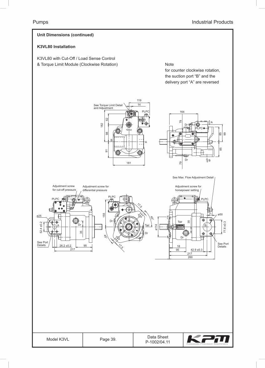
Unit Dimensions (continued)
K3VL80 Installation
K3VL80 with Cut-Off / Load Sense Control& Torque Limit Module (Clockwise Rotation)
Pumps Industrial Products
See Torque Limit Detailand Adjustment
See Max. Flow Adjustment Detail
Adjustment screw forhorsepower setting
Adjustment screw fordifferential pressure
Adjustment screwfor cut-off pressure
See PortDetails
See PortDetails
119
164
181
260217
17.5
17.5
95
ø50Lø25
A
95217
26.2 ±0.2
52.4
±0.
2
1842.9 ±0.3
77.8
±0.
3
91
182
7979
ø114
155
35
35
8585 9998
6214
PLPC
PLPC
PLPCPLPC
PLPC
TairTair
45°
45° Dr
DrDr
Dr
B
A
Dr
Dr
B
B
A
Notefor counter clockwise rotation,the suction port “B” and thedelivery port “A” are reversed

Data SheetP-1002/04.11Model K3VL Page 40.
Unit Dimensions (continued)K3VL80 Mounting Flange and Shaft Options
Pumps Industrial Products
ø181
ø180
SAE "C" 2 holeSAE J744-127-2
SAE "C" 30° Involute Spline Shaft
SAE J744-32-4 14T 12/24 DP
SAE "C" Straight ShaftSAE J744-32-1
Shaft end – ISO 3019/2-G32N
FlangeISO 3019/2-125A2HW
12.7
68
48
19
48
44
M8
25
58
504
M12
2838
ø31.
224
43
56
ø127
0 -0.0
5
0-0.5
ø125
h80 -0
.063
ø35.
2+0
.002
0
ø31.
75h7
0 -0.0
25
7.94
+0.0
020
9 +0.50
ø35
0 -0.3
10h9
0 -0.0
36
ø32k
6+0
.018
-0.0
02
SAE Type ISO Type
SAE “C” Spline Shaft SAE “C” Straight Shaft
ISO Straight Shaft

Data SheetP-1002/04.11Model K3VL Page 41.
Unit Dimensions (continued)
K3VL80 Rear Port
Pumps Industrial Products
PLPC
Dr
4-M14depth 19(0.75)
4-M12depth 22(0.87)
103.5(4.07)106.5(4.19)
Identificate marking forpump rotating direction
62(2.44) 55(2.17)
ø32(ø1.26)
10(0.39)30(1.18)
124(4.88)152(5.98)
ø64(ø2.52)
DrTair
95(3
.74)
125(
4.92
) 220(
8.66
)
197.
5(7.
78)
280(11.02)
Adapter tightening torque:12N.m(Not attached but supply with pump)
88.9
±0.3
3.50
±0.0
12)
31.8
±0.3
(1.2
5±0.
012)
66.7±0.3(2.63±0.012)
50.8±0.3(2.00±0.012)
K3VL80 Porting Details
Main SAE Flanged Ports
UNF Threaded Version ("S" in position 9 of model code)
Des. Port Name Port SizeTightening
Torque (Nm)Flange
Threads
A Delivery Port SAE J518C Std pressure (code 61) 1" 57 3/8-16UNC-2B x 18mm
B Suction Port SAE J518C Std pressure (code 61) 2" 98 1/2-13UNC-2B x 22mm
Auxiliary Ports
SAE Version ("S", "K", or "T" in position 8 of model)
Des. Port Name Port SizeTightening
Torque (Nm)
Dr Drain Port (x2) SAE J1926/1 Straight thread O ring boss1/2" OD Tube 3/4-16UNF-2B 98
PLPC Load Sensing PortPressure Control Port
SAE J1926/1 Straight thread O ring boss1/4" OD Tube 7/16-20UNF-2B 12
Tair Air Bleeder Port SAE J1926/1 Straight thread O ring boss1/4" OD Tube 7/16-20UNF-2B 12
ISO Version ("M" in position 8 of model code)
Dr Drain Port (x2) M22 x 1.5 DIN 3852 98
PLPC Load Sensing PortPressure Control Port M14 x 1.5 DIN 3852 25
Tair Air Bleeder Port M14 x 1.5 DIN 3852 25
Metric Version ("M" in position 9 of model code)
A Delivery Port SAE J518C Std pressure (code 61) 1" 57 M10 x 17
B Suction Port SAE J518C Std pressure (code 61) 2" 98 M12 x 20

Data SheetP-1002/04.11Model K3VL Page 42.
SAE "A" 2 holeSAE J744-82-2
Through Drive "A"
Through Drive "BB"
Through Drive "B"
Through Drive "C"
6 - M10Depth 17
Dr
TairB
PLPC
ø82.
55+0
.035
0
272 33
8
ø106
45°
SAE "A" 30° Involute SplineSAE J744-16-4 9T 16/32 DP
SAE "B" 2 holeSAE J744-101-2
4 - M12Depth 20
Dr
Tair
PLPC
ø101
.6+0
.035
0
29247
11
ø146
45°
SAE "B" 30° Involute SplineSAE J744-22-2 13T 16/32 DP
SAE "BB" 2 holeSAE J744-101-2
SAE "C" 2 holeSAE J744-127-2
4 - M12Depth 20
4 - M16Depth 24.5
Dr
TairB
B
PLPC
Dr
Tair
PLPC
ø101
.6+0
.035
0
ø127
+0.0
350
292
296.5
4711
5314
ø146
ø181
45°
45°
SAE "BB" 30°Involute SplineSAE J744-25-2 15T 16/32 DP
SAE "C" 30°Involute SplineSAE J744-33-4 15T 12/24 DP
Through Drive "C4"
SAE "C" 2 holeSAE J744-127-2
4 - M124 - M12 Through
B
Dr
Tair
PLPC
ø127
+0.0
350
301.55314
25° 25°
SAE "C" 30°Involute SplineSAE J744-33-4 15T 12/24 DP
Unit Dimensions (continued)
K3VL80 Through Drive Options
Pumps Industrial Products
Data SheetP-1002/04.11Model K3VL Page 43.
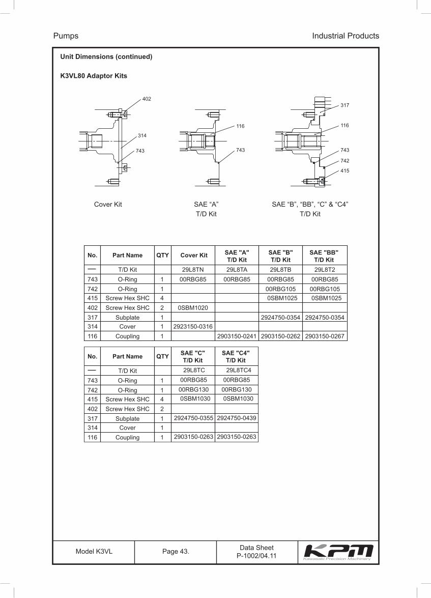
Unit Dimensions (continued)
K3VL80 Adaptor Kits
Pumps Industrial Products
402317
116
743
742
415
314
116
743743
No.
T/D Kit 29L8TN 29L8TA 29L8TB743 O-Ring 1 00RBG85 00RBG85 00RBG85742 O-Ring 1 00RBG105415 Screw Hex SHC 4 0SBM1025402 Screw Hex SHC 2 0SBM1020317 Subplate 1 2924750-0354314 Cover 1 2923150-0316116 Coupling 1 2903150-0241 2903150-0262
Part Name Cover KitQTY SAE "A"T/D Kit
SAE "B"T/D Kit
29L8T200RBG85
00RBG1050SBM1025
2924750-0354
2903150-0267
SAE "BB"T/D Kit
No.
T/D Kit743 O-Ring 1742 O-Ring 1415 Screw Hex SHC 4402 Screw Hex SHC 2317 Subplate 1314 Cover 1116 Coupling 1
Part Name QTY
29L8TC00RBG85
00RBG1300SBM1030
2924750-0355
2903150-0263
SAE "C"T/D Kit
29L8TC400RBG85
00RBG1300SBM1030
2924750-0439
2903150-0263
SAE "C4"T/D Kit
Cover Kit SAE “A”T/D Kit
SAE “B”, “BB”, “C” & “C4”T/D Kit

Data SheetP-1002/04.11Model K3VL Page 44.
Unit Dimensions (continued)
K3VL112/140 Installation
K3VL112/140 with Cut-Off / Load Sense Control& Torque Limit Module (Clockwise Rotation)
Pumps Industrial Products
Max Flow Adjustment
Adjustment screw forhorsepower setting
Adjustment screw fordifferential pressure
Adjustment screwfor cut-off pressure
See PortDetails
See PortDetails
19
ø64ø32
25031.8 ±0.3
66.7
±0.
3
106.5
113.3 113.3
10310398.5 23
106.5250
50.8 ±0.3
88.9
±0.
3
224
ø140
30
200
30
125
124
100
100
77152
188PLPC
PLPC
DrTair B
ADr
L
PLPCPLPC
TairTair
Dr
DrDr
ADr
Notefor counter clockwise rotation,the suction port “B” and thedelivery port “A” are reversed

Data SheetP-1002/04.11Model K3VL Page 45.
Unit Dimensions (continued)
K3VL112/140 (SAE D 4 BOLT) Mounting Flange & Shaft Options
Pumps Industrial Products
FlangeISO 3019/2
4-ø20 through
161.6
161.
6
SAE "D" 4 holeSAE J744-152-4
SAE "D" 30° Involute Spline Shaft
SAE J744-44-4 13T 8/16 DP SAE "D" Straight Shaft
SAE J744-44-1
7/16-14UNC-2B
Shaft end – ISO 3019/2 G45
ø152
.4h7
ø44.
447
ø48.
5
0 -0.0
63
ø180
h80 -0
.063
49.3
±0.
13
11.1
1h8
+0.0
30+0
.015
ø44.
45h7
0 -0.0
25
ø45k
6+0
.018
+0.0
02
14h9
0 +0.0
43
ø12.7 4-ø18 through
75
992
67
3 75
45
36
M16
60
67
63
28
38
0-0.5
ø224
45°
SAE “D” Type ISO Type
SAE “D” Spline Shaft SAE “D” Straight Shaft
ISO Straight Shaft

Data SheetP-1002/04.11Model K3VL Page 46.
Unit Dimensions (continued)
K3VL112/140 Rear Port
Pumps Industrial Products
PLPC
Dr
4-M14depth 19(0.75)
4-M12depth 22(0.87)
103.5(4.07)106.5(4.19)
Identificate marking forpump rotating direction
62(2.44) 55(2.17)
ø32(ø1.26)
10(0.39)30(1.18)
124(4.88)152(5.98)
ø64(ø2.52)
DrTair
95(3
.74)
125(
4.92
) 220(
8.66
)
197.
5(7.
78)
280(11.02)
Adapter tightening torque:12N.m(Not attached but supply with pump)
88.9
±0.3
3.50
±0.0
12)
31.8
±0.3
(1.2
5±0.
012)
66.7±0.3(2.63±0.012)
50.8±0.3(2.00±0.012)
K3VL112/140 Porting Details
Main SAE Flanged Ports
UNF Threaded Version ("S" in position 9 of model code)
Des. Port Name Port SizeTightening
Torque (Nm)Flange
Threads
A Delivery Port SAE J518C high pressure (code 62) 1 1/4" 157 1/2-13UNC-2B x 22mm
B Suction Port SAE J518C Std pressure (code 61) 2 1/2" 98 1/2-13UNC-2B x 22mm
Auxiliary Ports
SAE Version ("S", "K", "C", "R", "U", "X" or "T" in position 8 of model)
Des. Port Name Port SizeTightening
Torque (Nm)
Dr Drain Port (x2) SAE J1926/1 Straight thread O ring boss3/4" OD Tube 1 1/16-12UN-2B 167
PLPC Load Sensing PortPressure Control Port
SAE J1926/1 Straight thread O ring boss1/4" OD Tube 7/16-20UNF-2B 12
Tair Air Bleeder Port SAE J1926/1 Straight thread O ring boss1/4" OD Tube 7/16-20UNF-2B 12
ISO Version ("M" in position 8 of model code)
Dr Drain Port (x2) M27 x 2 DIN 3852 167
PLPC Load Sensing PortPressure Control Port M14 x 1.5 DIN 3852 25
Tair Air Bleeder Port M14 x 1.5 DIN 3852 25
Metric Version ("M" in position 9 of model code)
A Delivery Port SAE J518C high pressure (code 62) 1 1/4" 157 M14 x 19
B Suction Port SAE J518C Std pressure (code 61) 2 1/2" 98 M12 x 17
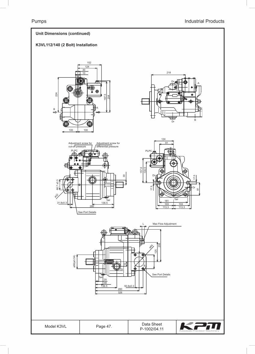
Data SheetP-1002/04.11Model K3VL Page 47.
Unit Dimensions (continued)
K3VL112/140 (2 Bolt) Installation
Pumps Industrial Products
152
218
Dr A
BDr
1243010
AB
100 100
30
157.
613
4.5
17.5
81
10
125
208
17.5
66.7
±0.
3
ø90(
ø3.5
4)
20422
4
197.
5
Adjustment screw forcut-off pressure
PLPC
See Port Details
See Port Details
326280
50.8±0.3136.54820
Dr
Tair
280136.5
Tair Tair181103 103
113.3 113.3
31.8±0.3
ø32
ø64
Adjustment screw fordifferential pressure
Max Flow Adjustment L
B
12491
PLPC
Dr
Dr
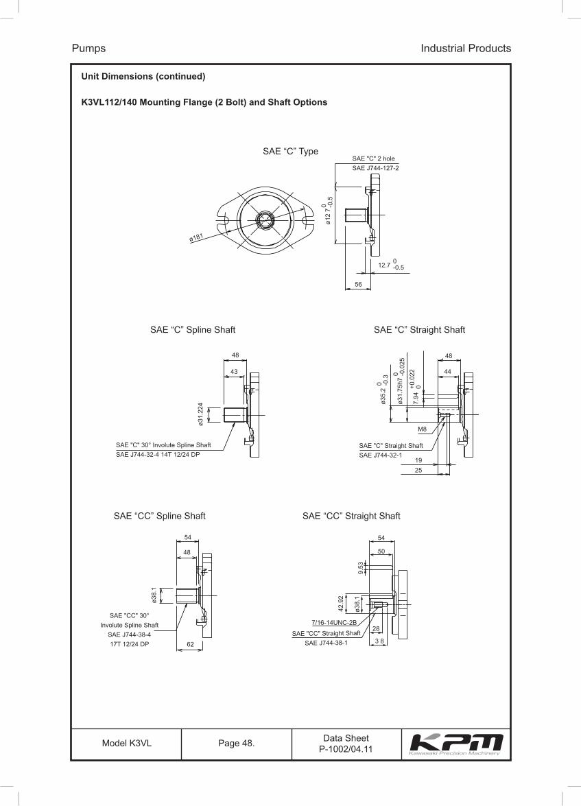
Data SheetP-1002/04.11Model K3VL Page 48.
Unit Dimensions (continued)
K3VL112/140 Mounting Flange (2 Bolt) and Shaft Options
Pumps Industrial Products
SAE "C" 2 holeSAE J744-127-2
SAE "C" 30° Involute Spline ShaftSAE J744-32-4 14T 12/24 DP
SAE "C" Straight ShaftSAE J744-32-1
56
48
ø31.
224 ø3
5.2
0 -0.3 0 -0
.025
+0.0
220
ø31.
75h7
7.94
19
M8
44
48
25
43
12.7 0-0.5
ø12
70 -0
.5
ø181
SAE "CC" 30°Involute Spline Shaft
SAE J744-38-417T 12/24 DP 62
48
ø38.
1
54
SAE "CC" Straight ShaftSAE J744-38-1
7/16-14UNC-2B
9.53
42.9
2
ø38.
1
54
50
28
3 8
SAE “C” Type
SAE “C” Spline Shaft
SAE “CC” Straight Shaft
SAE “C” Straight Shaft
SAE “CC” Spline Shaft

Data SheetP-1002/04.11Model K3VL Page 49.
Unit Dimensions (continued)
K3VL112/140 Through Drive Options
Pumps Industrial Products
SAE "A" 30° Involute SplineSAE J744-16-4 9T 16/32 DP
SAE "BB" 30° Involute SplineSAE J744-25-4 15T 16/32 DP
SAE "C4" 30° Involute SplineSAE J744-38-4 17T 12/24 DP
SAE "B" 30° Involute SplineSAE J744-22-4 13T 16/32 DP
SAE "C" 30° Involute SplineSAE J744-33-4 14T 12/24 DP
307.5
332.5
337.5
332.5
337.5
ø82.
55+0
.035
0ø1
01.6
+0.0
350
ø127
+0.0
350
ø101
.6+0
.035
0ø1
27+0
.035
0
6 - M10Depth 17
6 - M12Depth 25
4 - M12Depth 30
6 - M16Depth 30
6 - M12Depth 17
SAE "A" 2 holeSAE J744-82-2
SAE "BB" 2 holeSAE J744-101-2
SAE "C4" 2 holeSAE J744-127-2
SAE "C" 2 holeSAE J744-127-2
SAE "B" 2 holeSAE J744-101-2
45°
45°
ø106
45°
ø146
ø162
45°
ø181
ø146
PLPC
B
B
Tair Dr
B
Tair Dr
B
Tair Dr
Tair Dr
B
Tair Dr
11
53
14
58
SAE "D" 30° Involute SplineSAE J744-47-4 13T 8/16 DP
350.5
ø152
.4
161.
6±0.
2
+0.0
350
4 - M16 Depth 43161.6 ±0.2
SAE "D" 4 holeSAE J744-152-2
B
Tair Dr
15
71
11
53
14
59
8
31
Through Drive "A"
Through Drive "BB"
Through Drive "C4"
Through Drive "B"
Through Drive "C"
Through Drive "CC"
Through Drive "D"
SAE "CC" 30° Involute SplineSAE J744-38-4 17T 12/24 DP
337.5
ø127
+0.0
350
6 - M16Depth 30
SAE "CC" 2 holeSAE J744-127-2
45°
ø146
B
Tair Dr
14
59

Data SheetP-1002/04.11Model K3VL Page 50.
Unit Dimensions (continued)
K3VL112/140 Adaptor Kits
Pumps Industrial Products
402
314
743
116
743
317
116
743
742
415
317 317 317 317
116
743
742
415
116
743
742
415
116
743
742
415
116
743
742
415
Cover Kit
SAE "BB" T/D Kit SAE "C" & “C4” T/D Kit SAE "CC" T/D Kit SAE "D" T/D Kit
SAE "A" T/D Kit SAE "B" T/D Kit
No.
T/D Kit 29L8TN 29LHTA 29LHTB743 O-Ring 1 00RBG85 00RBG85 00RBG85742 O-Ring 1 00RBG105415 Screw Hex SHC 4 0SBM1230402 Screw Hex SHC 2 0SBM1020317 Subplate 1 2924750-0360314 Cover 1 2923150-0316116 Coupling 1 2903150-0268 2903150-0269
Part Name Cover KitQTY SAE "A"T/D Kit
SAE "B"T/D Kit
29LHT200RBG8500RBG1050SBM1230
2924750-0360
2903150-0270
SAE "BB"T/D Kit
No.
T/D Kit 29LHTC 29LHT3743 O-Ring 1 00RBG85 00RBG85742 O-Ring 1 00RBG13000RBG130415 Screw Hex SHC 4 0SBM12350SBM1235
2924750-0361Screw Hex SHC 2
317 Subplate 1 2924750-0361314 Cover 1116 Coupling 1 2903150-0271 2903150-0272
Part Name QTY SAE "C"T/D Kit
SAE "CC"T/D Kit
29LHT400RBG8500RBG1300SBM1235
2924750-0603
2903150-0272
SAE "C4"T/D Kit
29LHTD00RBG8500RBG1500SBM1250
2924750-0362
2903150-0273
SAE "D"T/D Kit
Data SheetP-1002/04.11Model K3VL Page 51.
Pumps Industrial Products
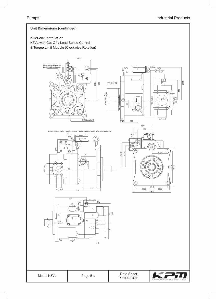
Unit Dimensions (continued)
K3VL200 InstallationK3VL with Cut-Off / Load Sense Control& Torque Limit Module (Clockwise Rotation)
PLPC PLPC
PLPC
PLPCDr
DrTair
B
A
221
134
115
115
PLPC
Dr
Adjustment screw for cut-off pressure Adjustment screw for differential pressure
12261.9 ±0.3
134
113.5
172.
5
53
Ø38
Ø76
149.
5
123.312229236.5 ±0.3
79.4
±0.
3
123.3224.5
264.5
224.
526
4.5
101
106.
4 ±0
.3
90 ±
0.1
106.
4 ±0
.3
26
53
Dr
A
X
X
B
162
Identificate marking forpump rotating direction
3010
219
212.
5
230.
5
140
2-M10 depth 17
ø165
.1h7
0 -0.0
5
SAE "E" 4 holeSAE J744-165-4

Data SheetP-1002/04.11Model K3VL Page 52.
Pumps Industrial Products
Unit Dimensions (continued)
K3VL200 Mounting Flange and Shaft Options
224.5
80
67
60
75
68
75
67
63
Ø44
.45
Ø49
.3Ø
44.4
5
11.1
1
SAE D Straight ShaftSAE J744-44-1
Ø50
.1
224.
5
Ø44
.447
88
4-ø22 through
SAE "D" 30° Involute Spline ShaftSAE J744-44-4 13T 8/16 DP
7/16-14UNC-2B
28
38
SAE "F" 30° Involute Spline ShaftSAE J744-50-4 15T 8/16 DP
SAE Type SAE Spline “D” Shaft
SAE Spline “F” Shaft SAE “D” Straight Shaft
Data SheetP-1002/04.11Model K3VL Page 53.
Pumps Industrial Products
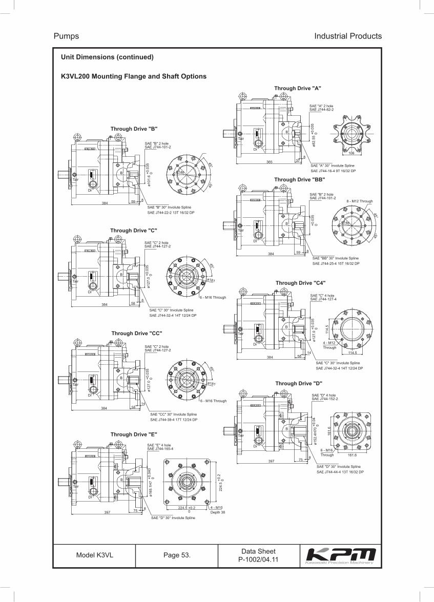
Unit Dimensions (continued)
K3VL200 Mounting Flange and Shaft Options
B
Tair
Dr
859384
ø101
.6+0
.035
0
SAE "B" 2 holeSAE J744-101-2
SAE "B" 30° Involute SplineSAE J744-22-2 13T 16/32 DP
8 - M12 Through
6 - M16 Through
ø146
45°
45°
ø146
ø181
45°
45°
45°
B
Tair
Dr
837365
SAE "A" 30° Involute SplineSAE J744-16-4 9T 16/32 DP
ø82.
55+0
.035
0
SAE "A" 2 holeSAE J744-82-2
106
B
Tair
Dr
SAE "B" 2 holeSAE J744-101-2
+0.0
350
SAE "BB" 30° Involute SplineSAE J744-25-4 15T 16/32 DP
859384
B
Tair
Dr
SAE "C" 30° Involute SplineSAE J744-32-4 14T 12/24 DP
858384
ø127
.0+0
.035
0
SAE "C" 2 holeSAE J744-127-2
Through Drive "B"
Through Drive "C"
Through Drive "BB"
Through Drive "A"
SAE "E" 4 holeSAE J744-165-4
ø165
.1H
7+0
.040
0
SAE "D" 30° Involute SplineSAE J744-44-4 13T 16/32 DP
875397
B
Tair
Dr
224.5 +0.20
4 - M10Depth 38
224.
5+0
.20
B
Tair
Dr
1458384
1458384
ø127
.0+0
.035
0
SAE "C" 2 holeSAE J744-127-2
SAE "CC" 30° Involute SplineSAE J744-38-4 17T 12/24 DP
6 - M16 Through
ø181
45°
B
Tair
Dr
SAE "C" 30° Involute SplineSAE J744-32-4 14T 12/24 DP
SAE "C" 4 holeSAE J744-127-4
ø127
.0+0
.035
0
114.5
114.
5
4 - M12 Through
B
Tair
Dr
875397
SAE "D" 4 holeSAE J744-152-2
SAE "D" 30° Involute SplineSAE J744-44-4 13T 16/32 DP
ø152
.4H
70+0
.04
0
161.
6
161.66 - M16 Through
Through Drive "CC"
Through Drive "E"
Through Drive "C4"
Through Drive "D"
Data SheetP-1002/04.11Model K3VL Page 54.
Unit Dimensions (continued)
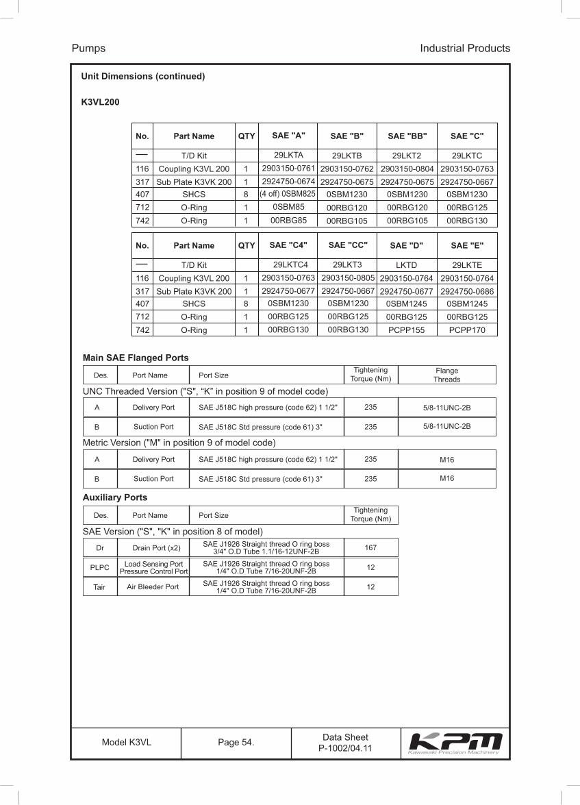
K3VL200
Pumps Industrial Products
No.
116 1317 1407 8
1742712
1
T/D KitCoupling K3VL 200Sub Plate K3VK 200
SHCSO-RingO-Ring
Part Name QTY
LKTD2903150-07642924750-0677
0SBM1245
PCPP15500RBG125
SAE "D"
29LKTE2903150-07642924750-0686
0SBM1245
PCPP17000RBG125
SAE "E"
No.
116 1317 1407 8
1742712
1
T/D KitCoupling K3VL 200Sub Plate K3VK 200
SHCSO-RingO-Ring
Part Name QTY
29LKTA2903150-07612924750-0674
(4 off) 0SBM8250SBM8500RBG85
SAE "A"
Main SAE Flanged Ports
UNC Threaded Version ("S", “K” in position 9 of model code)
Des. Port Name Port SizeTightening
Torque (Nm)Flange
Threads
A Delivery Port SAE J518C high pressure (code 62) 1 1/2" 235 5/8-11UNC-2B
B Suction Port SAE J518C Std pressure (code 61) 3" 235 5/8-11UNC-2B
Auxiliary Ports
SAE Version ("S", "K" in position 8 of model)
Des. Port Name Port SizeTightening
Torque (Nm)
Dr Drain Port (x2) SAE J1926 Straight thread O ring boss3/4" O.D Tube 1.1/16-12UNF-2B 167
PLPC Load Sensing PortPressure Control Port
SAE J1926 Straight thread O ring boss1/4" O.D Tube 7/16-20UNF-2B 12
Tair Air Bleeder Port SAE J1926 Straight thread O ring boss1/4" O.D Tube 7/16-20UNF-2B 12
Metric Version ("M" in position 9 of model code)
A Delivery Port SAE J518C high pressure (code 62) 1 1/2" 235 M16
B Suction Port SAE J518C Std pressure (code 61) 3" 235 M16
29LKTB 29LKT22903150-0762 2903150-0804
2924750-06752924750-06750SBM12300SBM1230
00RBG105 00RBG105
SAE "B" SAE "BB"
00RBG120 00RBG120
29LKTC2903150-07632924750-0667
0SBM1230
00RBG130
SAE "C"
00RBG125
29LKTC42903150-07632924750-0677
0SBM1230
00RBG130
SAE "C4"
00RBG125
29LKT32903150-08052924750-0667
0SBM1230
00RBG130
SAE "CC"
00RBG125

Data SheetP-1002/04.11Model K3VL Page 55.
Pumps Industrial Products
SAE “A” T/D Kit SAE “B” T/D Kit SAE “BB” T/D Kit
SAE “C” & “C4” T/D Kit SAE “CC” T/D Kit SAE “D” T/D Kit SAE “E” T/D Kit
Unit Dimensions (continued)
K3VL200 Through drive kits

Data SheetP-1002/04.11Model K3VL Page 56.
ALL RIGHTS RESERVED, SUBJECT TO REVISION
The specified data is for product descriptionpurposes only and may not be deemed to beguaranteed unless expressly confirmedin the contract.
KAWASAKI PRECISION MACHINERY (UK) LTDErnesettle, Plymouth, Devon, PL5 2SA, EnglandTel: +44 1752 364394 Fax: +44 1752 364816E Mail:[email protected] site: http://www.kpm-eu.com
Pumps Industrial Products