k2 wind power project wind turbine … · the siemens swt-2.3 turbine uses unique features such as...
TRANSCRIPT

K2 WIND POWER PROJECT WIND TURBINE SPECIFICATIONS REPORT
Prepared by: K2 Wind Ontario Limited Partnership
Suite105, 100 Simcoe Street Toronto, ON
M5H 3G2
In association with: Stantec Consulting Ltd.;
SENES Consultants Limited; and AMEC Environment & Infrastructure
November 2012
K2 Wind Ontario Limited Partnership K2 Wind Power Project Wind Turbine Specifications Report November 2012
Page i
TABLE OF CONTENTS
PAGE
1.0 INTRODUCTION .............................................................................................................................. 1
1.1 Project Overview ................................................................................................................. 1 1.2 Report Requirements .......................................................................................................... 1
2.0 TECHNICAL SPECIFICATIONS ..................................................................................................... 3
2.1 Siemens SWT-2.3 Wind Turbine ........................................................................................ 3 2.2 Acoustic Emissions Data .................................................................................................... 5
3.0 CLOSURE ........................................................................................................................................ 6
4.0 REFERENCES ................................................................................................................................. 7
LIST OF TABLES
Table 1-1: Wind Turbine Specifications Report Requirements per Ontario Regulation 359/09 .................. 2 Table 2-1: Basic Wind Turbine Specifications ............................................................................................. 3
LIST OF APPENDICES
APPENDIX A: Siemens SWT-2.3 Specifications

K2 Wind Ontario Limited Partnership K2 Wind Power Project Wind Turbine Specifications Report November 2012
Page 1
1.0 INTRODUCTION
1.1 Project Overview
K2 Wind Ontario Inc., in its capacity as general partner of K2 Wind Ontario Limited Partnership (the Proponent or K2 Wind), is proposing to develop, construct and operate the K2 Wind Power Project (the Project) in the Township of Ashfield-Colborne-Wawanosh (Township of ACW) north of Goderich within the County of Huron, Ontario. The Proponent is a limited partnership formed under the Limited Partnerships Act (Ontario), with K2 Wind Ontario Inc. as general partner and CP K2 Holdings Inc. (an affiliate of Capital Power Corporation), Samsung Renewable Energy Inc., and Pattern K2 LP Holdings LP (an affiliate of Pattern Renewable Holdings Canada ULC), as limited partners. The Project would supply approximately 270 megawatts (MW) of electricity to the Ontario power grid. The development of the Project would help the province of Ontario meet its goal of increasing the proportion of electricity generated from renewable sources. The Project is subject to Ontario Regulation 359/09 – Renewable Energy Approvals under Part V.0.1 of the Environmental Protection Act (O. Reg. 359/09).
Key Project components would consist of up to 140 wind turbines, electrical collection and communications systems including a transmission line, a transformer station, a substation, an operation and maintenance building, meteorological towers, access roads, and temporary construction and laydown areas.
The Proponent has elected to assess and seek approval for some alternative Project configurations. The Renewable Energy Approval (REA) application process will consider two potential transmission line voltages (138 kV vs. 230 kV), two potential transmission line routes, and several alternate access road and collector line alignments. Final selection of the sites to be used would be based on the results of consultation activities, detailed design / engineering work, and the conditions experienced during construction.
The Proponent retained Stantec Consulting Ltd., SENES Consultants Limited, and AMEC Environment & Infrastructure, a division of AMEC Americas Limited (AMEC) to assist in the preparation of the REA application with input from Timmins Martelle Heritage Consultants Inc., Selde Corporation and Zephyr North Canada.
1.2 Report Requirements
The purpose of the Wind Turbine Specifications Report is to provide specific technical information regarding the wind turbines proposed to be used for the Project.
The Wind Turbine Specifications Report has been prepared in accordance with Item 14, Table 1 of O. Reg. 359/09 and in consideration of the Ministry of the Environment’s (MOE’s) guidance document Technical Guide to Renewable Energy Approvals.
The following table provides the requirements of the Wind Turbine Specifications Report as prescribed in O. Reg. 359/09 and the relevant sections where it can be found within this document.
K2 Wind Ontario Limited Partnership K2 Wind Power Project Wind Turbine Specifications Report November 2012
Page 2
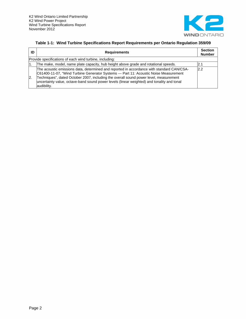
Table 1-1: Wind Turbine Specifications Report Requirements per Ontario Regulation 359/09
ID Requirements Section Number
Provide specifications of each wind turbine, including: 1. The make, model, name plate capacity, hub height above grade and rotational speeds. 2.1
2.
The acoustic emissions data, determined and reported in accordance with standard CAN/CSA-C61400-11-07, “Wind Turbine Generator Systems — Part 11: Acoustic Noise Measurement Techniques”, dated October 2007, including the overall sound power level, measurement uncertainty value, octave-band sound power levels (linear weighted) and tonality and tonal audibility.
2.2
K2 Wind Ontario Limited Partnership K2 Wind Power Project Wind Turbine Specifications Report November 2012
Page 3
2.0 TECHNICAL SPECIFICATIONS
2.1 Siemens SWT-2.3 Wind Turbine
The Project includes approximately 140 Siemens SWT-2.3 wind turbines. A summary of the basic specifications of the turbine model is provided in Table 2.1 below. A complete description of the general specifications for this turbine model is found in the manufacturer’s brochure provided as Appendix A.
Table 2-1: Basic Wind Turbine Specifications
Basic Wind Turbine Specifications Manufacturer Siemens
Model SWT-2.3-101 Name plate capacity (MW) Rated between 1.824 and 2.300 MW Hub height above grade 99.5 m Blade length 49 m Full blade diameter 101 m Blade sweep area 8,000 m2 Nominal revolutions (rotational speed)
6-16 rpm
Grid frequency 60 Hz Sound power nameplate (1.824 MW) 3 m/s – 91.4 dBA; 4 m/s – 95.3 dBA; 5 m/s – 98.1 dBA; 6 m/s – 100.5 dBA;
>7 m/s – 101.0 dBA Sound power nameplate (1.903 MW) 3 m/s – 91.4 dBA; 4 m/s – 95.5 dBA; 5 m/s – 99.0 dBA; 6 m/s – 101.5 dBA;
>7 m/s – 102.0 dBA Sound power nameplate (2.030 MW) 3 m/s – 91.4 dBA; 4 m/s – 95.6 dBA; 5 m/s – 99.8 dBA; 6 m/s – 102.5 dBA;
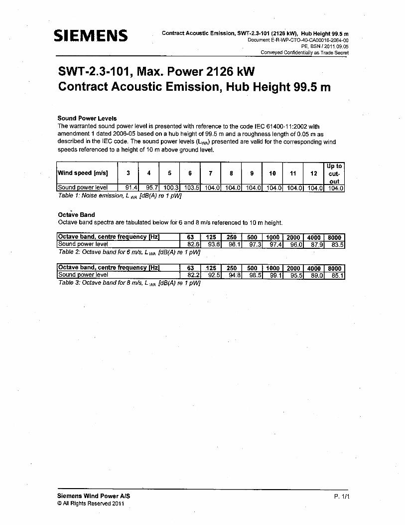
>7 m/s – 103.0 dBA Sound power nameplate (2.126 MW) 3 m/s – 91.4 dBA; 4 m/s – 95.7 dBA; 5 m/s – 100.3 dBA; 6 m/s – 103.5 dBA;
>7 m/s – 104.0 dBA Sound power nameplate (2.221 MW) 3 m/s – 91.4 dBA; 4 m/s – 95.7 dBA; 5 m/s – 100.5 dBA; 6 m/s – 104.5 dBA;
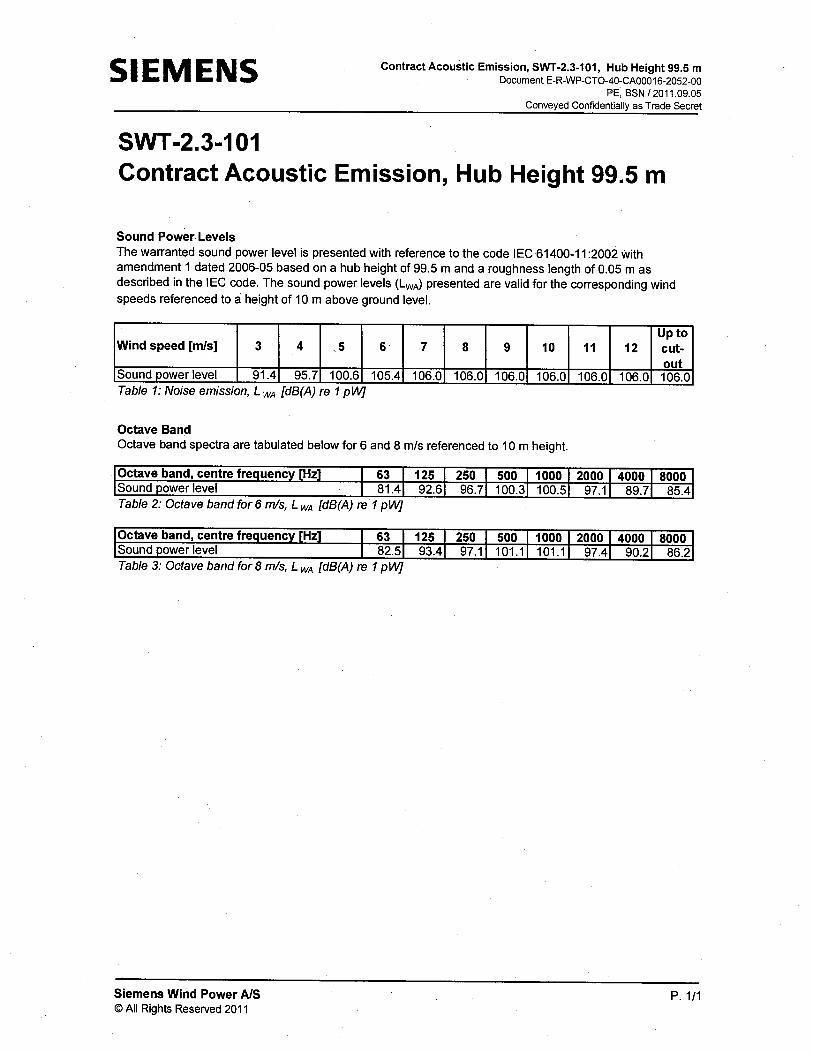
>7 m/s – 105.0 dBA Sound power (nameplate 2.300 MW) 3 m/s – 91.4 dBA; 4 m/s – 95.7 dBA; 5 m/s – 100.6 dBA; 6 m/s – 105.4 dBA;
>7 m/s – 106.0 dBA
Each wind turbine consists of eight key components:
• concrete tower foundation; • five steel tower sections; • nacelle (comprised of gearbox, electrical generator, and housing); • three rotor blades; • hub (the structure to where the blades attach); • power convertor; • padmount transformer at the base of the tower; and • electrical wiring and grounding.

K2 Wind Ontario Limited Partnership K2 Wind Power Project Wind Turbine Specifications Report November 2012
Page 4
The tower would be supported by a concrete foundation, approximately 3 m deep, depending upon subsurface conditions. The turbine tower has internal ascent and direct access to the yaw system and nacelle. It is equipped with platforms and internal electric lighting. The tower height for the Siemens SWT-2.3 turbine is 99.5 m.
The tower supports the nacelle which is accessible via a hatch in the floor and houses the main components of the wind turbine including:
• Main bearing; • Main shaft; • Gearbox; • Brake disc; • Coupling; • Generator; • Service crane; • Yaw ring; • Yaw gear; • Nacelle bedplate; • Oil filter; • Canopy; and • Generator fan.
The rotor hub is cast in nodular cast iron and is fitted to the main shaft with a flange connection. The hub is sufficiently large to provide a comfortable working environment for two service technicians during maintenance of the blade roots and pitch bearings from inside the structure.
The Siemens SWT-2.3 turbine uses unique features such as NetConverter® power conversion system which allows generator operation at variable speed, frequency and voltage while supplying power at a constant frequency and voltage to the MV transformer. The 101 m rotor supports three blades and a hub. Each blade is constructed of fibreglass reinforced epoxy in Siemens’ proprietary IntegralBlade® manufacturing process. The blades are 49 m in length. Each blade has its own independent pitching mechanism capable of feathering the blade under any operating condition. The blade pitch arrangement allows for optimization of the power output throughout the operating range, and the blades are feathered during standstill to minimize wind loads.
Electrical wiring includes a 690 V cable which runs down the turbine tower to the padmount transformer located adjacent to the tower base. A padmount transformer, located adjacent to the base of each wind turbine, is required to transform the electricity created in the nacelle to a standard operating power line voltage (i.e. 690 V to 34.5 kV). The converter is also located at the base of the turbine and controls the energy conversion in the generator by feeding power to and from the grid. From the padmount transformer, underground 34.5 kV collector lines would carry the electricity from the turbines to the collector line system.
K2 Wind Ontario Limited Partnership K2 Wind Power Project Wind Turbine Specifications Report November 2012
Page 5
Turbine tower lighting would be in accordance with Transport Canada Regulations and Standards as described in the Design and Operations Report.
2.2 Acoustic Emissions Data
The Siemens SWT-2.3 wind-powered turbines are rated to operate between 1.824 and 2.300 MW. The maximum overall sound power rating of the highest rated turbines (2.300 MW) is 106.0 dBA. Information regarding the acoustic emissions of the turbine, including the overall sound power level, measurement uncertainty value, octave-band sound power levels, and tonality and tonal audibility, is available in the manufacturer specifications provided in Appendix A.
K2 Wind Ontario Limited Partnership K2 Wind Power Project Wind Turbine Specifications Report November 2012
Page 6
3.0 CLOSURE
K2 Wind Ontario Limited Partnership, in association with Stantec Consulting Ltd., SENES Consultants Limited, and AMEC Environment and Infrastructure, has completed this report for the exclusive use of the Proponent for specific application to the Project. The work has been completed in accordance with Ontario Regulation 359/09, and in consideration of the guidance document Technical Guide to Renewable Energy Approvals.
Prepared by:
Kara Hearne
Project Manager Stantec Consulting Ltd.
Sarah Palmer
Senior Environmental Advisor Capital Power Corporation for K2 Wind Ontario Limited Partnership.
rpt_60738_wtsr_201211_final.docx
K2 Wind Ontario Limited Partnership K2 Wind Power Project Wind Turbine Specifications Report November 2012
Page 7
4.0 REFERENCES
Ontario Regulation 359/09. Renewable Energy Approvals Under Part V.0.1 of the Act made under the Environmental Protection Act.
Ontario Ministry of the Environment. 2011 & 2012. Technical Guide to Renewable Energy Approvals. Queen’s Printer for Ontario. PIBS 8472e.

K2 Wind Ontario Limited Partnership K2 Wind Power Project Wind Turbine Specifications Report November 2012
APPENDIX A: Siemens SWT-2.3 Specifications

Noise Measurement,
Ejler Kristensen / AJJ 25/06/2012For Internal use only
Siemens Wind Power A/S © All Rights Reserved 2008
1 / 16Noise Measurement, 16 April 2011.doc
Noise Measurement SWP Report N-2304 099-T1 Ejler Kristensen 25.05.2011

Noise Measurement,
Ejler Kristensen / AJJ 25/06/2012For Internal use only
Siemens Wind Power A/S © All Rights Reserved 2008
2 / 16Noise Measurement, 16 April 2011.doc
Contents 1 Measurement ...........................................................................................................................4 2 Conclusion...............................................................................................................................4
2.1 Results............................................................................................................................... 4 3 Analysis of Sound Power Level .............................................................................................5
3.1 Sound Power Level .......................................................................................................... 5 4 Analyses of Tonality ...............................................................................................................8
4.1 Info ..................................................................................................................................... 8 4.1.1 Tonal analysis method............................................................................................... 8
4.2 Tonal analysis at 6 m/s .................................................................................................... 8 4.2.1 Tonality analysis at 117.5 Hz..................................................................................... 9
4.3 Tonal analysis at 7 m/s .................................................................................................... 9 4.3.1 Tonality analysis at 118.8 Hz................................................................................... 10 4.3.2 Tonality analysis at 495.3 Hz................................................................................... 10
4.4 Tonal analysis at 8 m/s .................................................................................................. 11 4.4.1 Tonality analysis at 517.3 Hz................................................................................... 11
4.5 Tonal analysis at 9 m/s .................................................................................................. 12 4.5.1 Tonality analysis at 517.8 Hz................................................................................... 12
4.6 Tonal analysis at 10 m/s ................................................................................................ 13 4.6.1 Tonality analysis at 519.3 Hz................................................................................... 13
Appendix 1 Non acoustic measurements 10 s average ...........................................................14
Appendix 2 Acoustic overall analyzer measurements 10 s average.......................................16
Noise Measurement,
Ejler Kristensen / AJJ 25/06/2012y For Internal use onl
Siemens Wind Power A/S © All Rights Reserved 2008
3 / 16Noise Measurement, 16 April 2011.doc
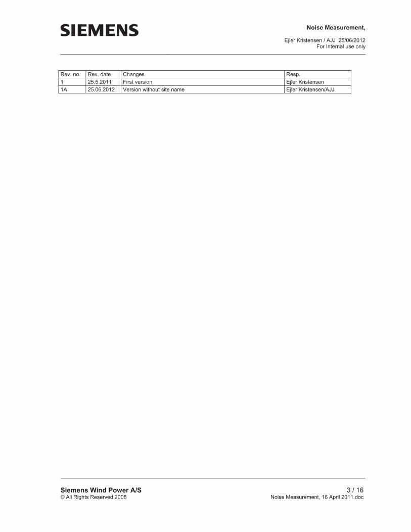
Rev. no. Rev. date Changes Resp. 1 25.5.2011 First version Ejler Kristensen 1A 25.06.2012 Version without site name Ejler Kristensen/AJJ

Noise Measurement,
Ejler Kristensen / AJJ 25/06/2012y For Internal use onl
Siemens Wind Power A/S © All Rights Reserved 2008
4 / 16Noise Measurement, 16 April 2011.doc
1 Measurement
The measurement was performed at turbine xx at xxxxxx Wind farm in Ontario on 16th April 2011 from 14:43 to 18:07 by Ejler Kristensen, Siemens Wind Power. The measurement computer time was synchronized with the turbine computer time. The turbine type is SWT-2.3-101 with turbine ID no. 230x-xxxx. The hub height wind speed range from 4.6 m/s - 14.0 m/s measured as 10 sec average with the nacelle anemometer, and the power output from 430 kW - 2300 kW. 10 sec average non acoustic measurements are shown in appendix 1. The measurement fulfils IEC61400-11:2002 with following exceptions:
The nacelle anemometer is used for background noise wind speed measurements.
2 Conclusion
A noise measurement has been performed at turbine xx at xxxxxx Wind Farm.
2.1 Results The results are shown in table 2.1 below: Wind speed BIN [m/s] - 10 m 5 6 7 8 9 10
LWA [dB re. 1 pW] 101.7 104.4 104.9 105.1 105.6 105.1
Tone average frequency, f [Hz] - 117.5 118.8 517.3 517.8 519.3
Max. tonality, Lk [dB] - - 6.7 -5.2 -2.9 -1.5 -0.2
Max. tonal audibility, La,k [dB] - -4.7 -3.2 -0.6 0.8 2.1 Table 2.1: Results of the measurements Sound power levels, LWA, of the turbine are below guaranteed values. The level of tonality in the reference position (near field) is acceptable. The maximum tonality measured in the reference position is -0.2 dB at 519.3 Hz, which corresponds to an audibility of 2.1 dB.

Noise Measurement,
Ejler Kristensen / AJJ 25/06/2012For Internal use only
Siemens Wind Power A/S © All Rights Reserved 2008
5 / 16Noise Measurement, 16 April 2011.doc
3 Analysis of Sound Power Level
3.1 Sound Power Level The sound power level, LWA, is calculated according to IEC61400-11:2002. Figure 3.1 shows measured sound pressure levels. Table 3.1 shows the resulting sound power level without extrapolation of the regression results. Microphone: Signal 1_130 m ref: [Pa] Date: 16-04-2011 Engineer: EJK Location: XXXXX in Ontario Turbine-ID: T1 Hub Height: 80m Distance: 130m Roughness: 0,05m K-Faktor: 0.7418 V_P/V_Anemo: 1.041 Calibrator with serial type 4231 serial no. 2326419 has been measured to 93,89 dB at Brüel & Kjær – Nærum DK with reference to calibration letter of 25. maj 2011. The calibrating signal was measured to 93,8 dB at the beginning of the measurement. See appendix 2

Noise Measurement,
Ejler Kristensen / AJJ 25/06/2012For Internal use only
Siemens Wind Power A/S © All Rights Reserved 2008
6 / 16Noise Measurement, 16 April 2011.doc
Figure 3.1: Measured background noise and total noise Windspeed [m/s] 10 m 5 6 7 8 9 10 Averaged 2 PitchBladeB: [deg] -1,67 -2,52 -1,57 0,9 3,86 7,27 Averaged 5 MainSRpm: [RPM] 13,14 14,44 14,55 15,23 15,55 15,62 Averaged 6 ActPower: [kW] 824,93 1397,41 1885 2259,79 2296,43 2295,79Averaged 7 AcWindSp: [m/s] 7,1 8,12 9,5 10,73 11,99 13,43 Averaged 8 GenRpm: [RPM] 1190,69 1308,2 1318,88 1379,96 1409,2 1415,96Laeq total [dB(A) re 20 μPa] 53,1 55,85 56,33 56,58 57,04 56,63 Laeq BG [dB(A) re 20 μPa] 36,52 38,35 39,96 41,35 42,51 43,45 Laeq BG corr. [dB(A) re 20 μPa] 53,01 55,78 56,23 56,44 56,89 56,41 LWA [dB(A) re pW] 101,67 104,44 104,90 105,11 105,55 105,08 *) difference between LAeg total and LAeq BG is between 3 and 6 dB(A) Table 3.1: Turbine noise
Noise Measurement,
Ejler Kristensen / AJJ 25/06/2012For Internal use only
Siemens Wind Power A/S © All Rights Reserved 2008
7 / 16Noise Measurement, 16 April 2011.doc
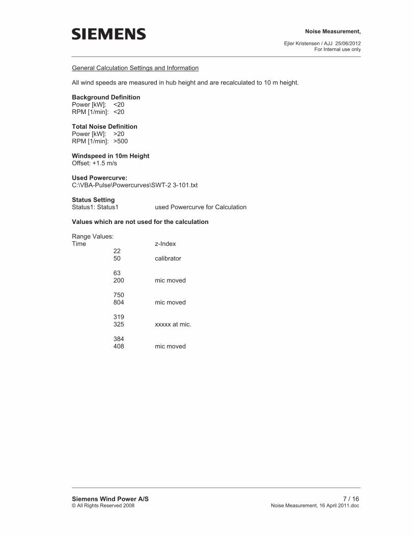
General Calculation Settings and Information All wind speeds are measured in hub height and are recalculated to 10 m height. Background Definition Power [kW]: <20 RPM [1/min]: <20 Total Noise Definition Power [kW]: >20 RPM [1/min]: >500 Windspeed in 10m Height Offset: +1.5 m/s Used Powercurve: C:\VBA-Pulse\Powercurves\SWT-2 3-101.txt Status Setting Status1: Status1 used Powercurve for Calculation Values which are not used for the calculation Range Values: Time z-Index 22 50 calibrator 63 200 mic moved 750 804 mic moved 319 325 xxxxx at mic. 384 408 mic moved

Noise Measurement,
Ejler Kristensen / AJJ 25/06/2012For Internal use only
Siemens Wind Power A/S © All Rights Reserved 2008
8 / 16Noise Measurement, 16 April 2011.doc
4 Analyses of Tonality
4.1 Info Txxx, ID no. 23xx-xxxx.
4.1.1 Tonal analysis method The tonal analysis presented in this report is performed according to the L70 method as described in IEC 61400-11:2002. Due to air absorption, different level of masking noise etc. tonal analysis in the reference position is not comparable with tonality analysis in the far field. Wind speeds in the tonal analysis are given at 10 m height.
4.2 Tonal analysis at 6 m/s The 2 periods of 1 minute with averaged wind speeds closest to 6 m/s are used for this tonal analysis. The twelve 10 sec. FFT spectra are shown in Figure 4.1 below.
Figure 4.1: The twelve 10 sec FFT spectra used for tonal analysis.

Noise Measurement,
Ejler Kristensen / AJJ 25/06/2012For Internal use only
Siemens Wind Power A/S © All Rights Reserved 2008
9 / 16Noise Measurement, 16 April 2011.doc
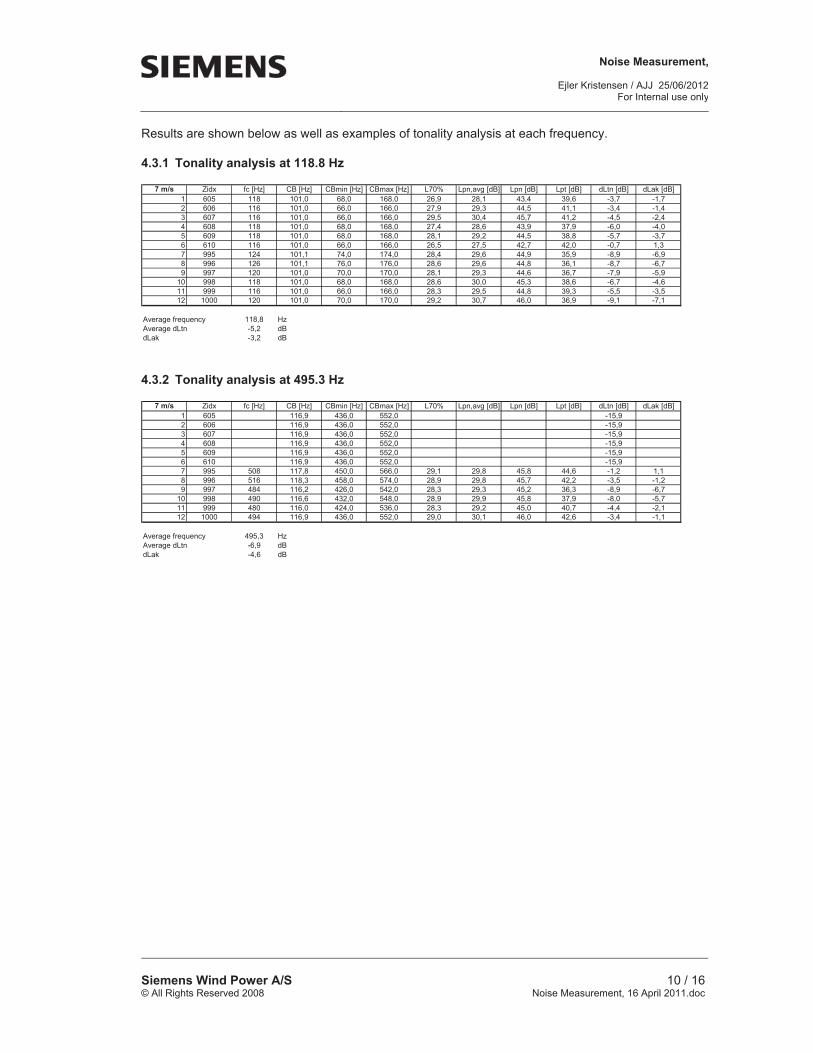
Results are shown below as well as examples of tonality analysis at each frequency.
4.2.1 Tonality analysis at 117.5 Hz
6 m/s Zidx fc [Hz] CB [Hz] CBmin [Hz] CBmax [Hz] L70% Lpn,avg [dB] Lpn [dB] Lpt [dB] dLtn [dB] dLak [dB]1 248 101,0 68,0 168,0 -15,32 249 101,0 68,0 168,0 -15,33 250 101,0 68,0 168,0 -15,34 251 101,0 68,0 168,0 -15,35 252 101,0 68,0 168,0 -15,36 253 101,0 68,0 168,0 -15,37 347 101,0 68,0 168,0 -15,38 348 101,0 68,0 168,0 -15,39 349 118 101,0 68,0 168,0 27,1 28,4 43,6 41,5 -2,2 -0,2
10 350 118 101,0 68,0 168,0 26,3 27,5 42,7 40,4 -2,3 -0,311 351 118 101,0 68,0 168,0 26,4 27,7 43,0 40,5 -2,5 -0,512 352 116 101,0 66,0 166,0 26,4 27,7 43,0 40,5 -2,5 -0,5
Average frequency 117,5 HzAverage dLtn -6,7 dBdLak -4,7 dB
4.3 Tonal analysis at 7 m/s The 2 periods of 1 minute with averaged wind speeds closest to 7 m/s are used for this tonal analysis. The twelve 10 sec. FFT spectra are shown in Figure 4.2 below.
Figure 4.2: The twelve 10 sec FFT spectra used for tonal analysis.
Noise Measurement,
Ejler Kristensen / AJJ 25/06/2012For Internal use only
Siemens Wind Power A/S © All Rights Reserved 2008
10 / 16Noise Measurement, 16 April 2011.doc
Results are shown below as well as examples of tonality analysis at each frequency.
4.3.1 Tonality analysis at 118.8 Hz
7 m/s Zidx fc [Hz] CB [Hz] CBmin [Hz] CBmax [Hz] L70% Lpn,avg [dB] Lpn [dB] Lpt [dB] dLtn [dB] dLak [dB]1 605 118 101,0 68,0 168,0 26,9 28,1 43,4 39,6 -3,7 -1,72 606 116 101,0 66,0 166,0 27,9 29,3 44,5 41,1 -3,4 -1,43 607 116 101,0 66,0 166,0 29,5 30,4 45,7 41,2 -4,5 -2,44 608 118 101,0 68,0 168,0 27,4 28,6 43,9 37,9 -6,0 -4,05 609 118 101,0 68,0 168,0 28,1 29,2 44,5 38,8 -5,7 -3,76 610 116 101,0 66,0 166,0 26,5 27,5 42,7 42,0 -0,7 1,37 995 124 101,1 74,0 174,0 28,4 29,6 44,9 35,9 -8,9 -6,98 996 126 101,1 76,0 176,0 28,6 29,6 44,8 36,1 -8,7 -6,79 997 120 101,0 70,0 170,0 28,1 29,3 44,6 36,7 -7,9 -5,9
10 998 118 101,0 68,0 168,0 28,6 30,0 45,3 38,6 -6,7 -4,611 999 116 101,0 66,0 166,0 28,3 29,5 44,8 39,3 -5,5 -3,512 1000 120 101,0 70,0 170,0 29,2 30,7 46,0 36,9 -9,1 -7,1
Average frequency 118,8 HzAverage dLtn -5,2 dBdLak -3,2 dB
4.3.2 Tonality analysis at 495.3 Hz
7 m/s Zidx fc [Hz] CB [Hz] CBmin [Hz] CBmax [Hz] L70% Lpn,avg [dB] Lpn [dB] Lpt [dB] dLtn [dB] dLak [dB]1 605 116,9 436,0 552,0 -15,92 606 116,9 436,0 552,0 -15,93 607 116,9 436,0 552,0 -15,94 608 116,9 436,0 552,0 -15,95 609 116,9 436,0 552,0 -15,96 610 116,9 436,0 552,0 -15,97 995 508 117,8 450,0 566,0 29,1 29,8 45,8 44,6 -1,2 1,18 996 516 118,3 458,0 574,0 28,9 29,8 45,7 42,2 -3,5 -1,29 997 484 116,2 426,0 542,0 28,3 29,3 45,2 36,3 -8,9 -6,7
10 998 490 116,6 432,0 548,0 28,9 29,9 45,8 37,9 -8,0 -5,711 999 480 116,0 424,0 536,0 28,3 29,2 45,0 40,7 -4,4 -2,112 1000 494 116,9 436,0 552,0 29,0 30,1 46,0 42,6 -3,4 -1,1
Average frequency 495,3 HzAverage dLtn -6,9 dBdLak -4,6 dB

Noise Measurement,
Ejler Kristensen / AJJ 25/06/2012For Internal use only
Siemens Wind Power A/S © All Rights Reserved 2008
11 / 16Noise Measurement, 16 April 2011.doc
4.4 Tonal analysis at 8 m/s The 2 periods of 1 minute with averaged wind speeds closest to 8 m/s are used for this tonal analysis. The twelve 10 sec. FFT spectra are shown in Figure 4.3 below.
Figure 4.3: The twelve 10 sec FFT spectra used for tonal analysis. Results are shown below as well as examples of tonality analysis at each frequency.
4.4.1 Tonality analysis at 517.3 Hz
8 m/s Zidx fc [Hz] CB [Hz] CBmin [Hz] CBmax [Hz] L70% Lpn,avg [dB] Lpn [dB] Lpt [dB] dLtn [dB] dLak [dB]1 1007 516 118,3 458,0 574,0 26,6 27,8 43,8 41,5 -2,2 0,12 1008 514 118,2 456,0 572,0 28,3 29,3 45,2 39,9 -5,3 -3,03 1009 522 118,7 464,0 580,0 28,6 29,5 45,4 40,4 -5,0 -2,74 1010 504 117,5 446,0 562,0 29,1 30,6 46,6 38,8 -7,7 -5,45 1011 118,5 460,0 576,0 -16,06 1012 518 118,5 460,0 576,0 27,6 28,9 44,9 35,5 -9,4 -7,17 1115 520 118,6 462,0 578,0 28,4 29,5 45,4 43,3 -2,1 0,28 1116 518 118,5 460,0 576,0 28,0 28,9 44,8 41,3 -3,5 -1,29 1117 516 118,3 458,0 574,0 27,5 28,3 44,3 44,9 0,6 2,9
10 1118 522 118,7 464,0 580,0 27,8 28,9 44,9 43,0 -1,9 0,511 1119 516 118,3 458,0 574,0 28,2 28,9 44,8 44,9 0,1 2,412 1120 524 118,9 466,0 582,0 27,4 28,5 44,4 43,1 -1,4 1,0
Average frequency 517,3 HzAverage dLtn -2,9 dBdLak -0,6 dB

Noise Measurement,
Ejler Kristensen / AJJ 25/06/2012For Internal use only
Siemens Wind Power A/S © All Rights Reserved 2008
12 / 16Noise Measurement, 16 April 2011.doc
4.5 Tonal analysis at 9 m/s The 2 periods of 1 minute with averaged wind speeds closest to 9 m/s are used for this tonal analysis. The twelve 10 sec. FFT spectra are shown in Figure 4.4 below.
Figure 4.4: The twelve 10 sec FFT spectra used for tonal analysis. Results are shown below as well as examples of tonality analysis at each frequency.
4.5.1 Tonality analysis at 517.8 Hz
9 m/s Zidx fc [Hz] CB [Hz] CBmin [Hz] CBmax [Hz] L70% Lpn,avg [dB] Lpn [dB] Lpt [dB] dLtn [dB] dLak [dB]1 1037 518 118,5 460,0 576,0 26,8 27,9 43,9 42,2 -1,7 0,62 1038 522 118,7 464,0 580,0 27,4 28,3 44,3 41,5 -2,9 -0,53 1039 510 117,9 452,0 568,0 25,8 26,6 42,5 40,5 -2,1 0,24 1040 518 118,5 460,0 576,0 28,4 29,4 45,4 41,0 -4,4 -2,15 1041 512 118,1 454,0 570,0 26,6 27,2 43,2 43,7 0,5 2,86 1042 512 118,1 454,0 570,0 27,6 28,4 44,4 43,3 -1,1 1,27 1061 524 118,9 466,0 582,0 28,2 29,3 45,2 41,1 -4,1 -1,88 1062 528 119,1 470,0 586,0 26,7 27,9 43,9 39,3 -4,6 -2,39 1063 520 118,6 462,0 578,0 26,3 27,3 43,3 41,3 -1,9 0,4
10 1064 514 118,2 456,0 572,0 25,3 26,6 42,5 43,2 0,7 3,011 1065 522 118,7 464,0 580,0 26,5 27,5 43,5 42,8 -0,6 1,712 1066 514 118,2 456,0 572,0 25,9 26,6 42,5 42,8 0,2 2,5
Average frequency 517,8 HzAverage dLtn -1,5 dBdLak 0,8 dB

Noise Measurement,
Ejler Kristensen / AJJ 25/06/2012For Internal use only
Siemens Wind Power A/S © All Rights Reserved 2008
13 / 16Noise Measurement, 16 April 2011.doc
4.6 Tonal analysis at 10 m/s The 2 periods of 1 minute with averaged wind speeds closest to 10 m/s are used for this tonal analysis. The twelve 10 sec. FFT spectra are shown in Figure 4.5 below.
Figure 4.5: The twelve 10 sec FFT spectra used for tonal analysis. Results are shown below as well as examples of tonality analysis at each frequency.
4.6.1 Tonality analysis at 519.3 Hz
10 m/s Zidx fc [Hz] CB [Hz] CBmin [Hz] CBmax [Hz] L70% Lpn,avg [dB] Lpn [dB] Lpt [dB] dLtn [dB] dLak [dB]1 1031 528 119,1 470,0 586,0 26,8 27,7 43,7 44,3 0,7 3,02 1032 518 118,5 460,0 576,0 26,3 27,3 43,3 41,0 -2,3 0,03 1033 520 118,6 462,0 578,0 26,3 27,2 43,1 46,1 3,0 5,34 1034 518 118,5 460,0 576,0 26,4 27,3 43,3 42,6 -0,6 1,75 1035 516 118,3 458,0 574,0 26,6 27,4 43,4 43,7 0,4 2,76 1036 516 118,3 458,0 574,0 26,6 27,5 43,4 45,4 1,9 4,27 1091 520 118,6 462,0 578,0 26,2 27,3 43,3 41,9 -1,4 1,08 1092 520 118,6 462,0 578,0 26,2 26,9 42,9 41,8 -1,1 1,29 1093 524 118,9 466,0 582,0 26,3 27,7 43,7 37,3 -6,3 -4,0
10 1094 514 118,2 456,0 572,0 25,6 26,5 42,5 41,2 -1,3 1,011 1095 514 118,2 456,0 572,0 26,1 27,1 43,0 42,5 -0,5 1,812 1096 524 118,9 466,0 582,0 26,6 27,5 43,5 42,7 -0,8 1,5
Average frequency 519,3 HzAverage dLtn -0,2 dBdLak 2,1 dB

Noise Measurement,
Ejler Kristensen / AJJ 25/06/2012For Internal use only
Siemens Wind Power A/S © All Rights Reserved 2008
14 / 16Noise Measurement, 16 April 2011.doc
Appendix 1 Non acoustic measurements 10 s average Averaged(7 AcWindSp) - Input
Working : Input : Multi-buffer 1 : Aux Logger
0 100 200 300 400 500 600 700 800 900 1k 1,1k 1,2k 1,3k
0
2
4
6
8
10
12
14
16
18
20
[] (Nominal Values)
[m/s] Averaged(7 AcWindSp) - InputWorking : Input : Multi-buffer 1 : Aux Logger
0 100 200 300 400 500 600 700 800 900 1k 1,1k 1,2k 1,3k
0
2
4
6
8
10
12
14
16
18
20
[] (Nominal Values)
[m/s]
Meas start 14:43 Meas stop 18:02
Figure A1.1: Dark green line: Measured 10 s avg. wind speed from the nacelle anemometer.
Averaged(6 ActPower) - InputWorking : Input : Multi-buffer 1 : Aux Logger
0 100 200 300 400 500 600 700 800 900 1k 1,1k 1,2k 1,3k
0
400
800
1,2k
1,6k
2k
2,4k
2,8k
[] (Nominal Values)
[kW] Averaged(6 ActPower) - InputWorking : Input : Multi-buffer 1 : Aux Logger
0 100 200 300 400 500 600 700 800 900 1k 1,1k 1,2k 1,3k
0
400
800
1,2k
1,6k
2k
2,4k
2,8k
[] (Nominal Values)
[kW]
Figure A1.2: Dark green line: Measured 10 s avg. produced power. Light green line shows max instantaneous measurements within the averaging period.

Noise Measurement,
Ejler Kristensen / AJJ 25/06/2012For Internal use only
Siemens Wind Power A/S © All Rights Reserved 2008
15 / 16Noise Measurement, 16 April 2011.doc
Averaged(4 YawPos) - InputWorking : Input : Multi-buffer 1 : Aux Logger
0 100 200 300 400 500 600 700 800 900 1k 1,1k 1,2k 1,3k
0
40
80
120
160
200
240
280
[] (Nominal Values)
[deg] Averaged(4 YawPos) - InputWorking : Input : Multi-buffer 1 : Aux Logger
0 100 200 300 400 500 600 700 800 900 1k 1,1k 1,2k 1,3k
0
40
80
120
160
200
240
280
[] (Nominal Values)
[deg]
Ref.pos 150 new ref.pos
Z63 yaw out of limit
212 new ref
new ref 232
Figure A1.3: Dark green line: Measured 10 s avg. yaw position.

Noise Measurement,
Ejler Kristensen / AJJ 25/06/2012For Internal use only
Siemens Wind Power A/S © All Rights Reserved 2008
16 / 16Noise Measurement, 16 April 2011.doc
Appendix 2 Acoustic overall analyzer measurements 10 s average
Figure A2.1: Dark green line: Measured 10 s avg. overall analyzer values.
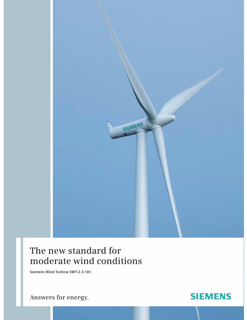
The new standard for moderate wind conditions Siemens Wind Turbine SWT-2.3-101
Answers for energy.
2
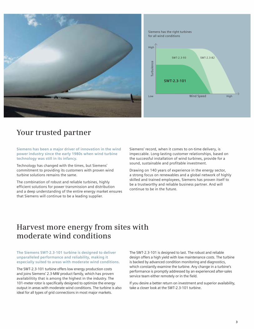
Harvest more energy from sites with moderate wind conditions
The Siemens SWT-2.3-101 turbine is designed to deliver unparalleled performance and reliability, making it especially suited to areas with moderate wind conditions.
The SWT-2.3-101 turbine offers low energy production costsand joins Siemens’ 2.3-MW product family, which has proven availabilitity that is among the highest in the industry. The 101-meter rotor is specifically designed to optimize the energy output in areas with moderate wind conditions. The turbine is also ideal for all types of grid connections in most major markets.
Your trusted partner
Siemens has been a major driver of innovation in the wind power industry since the early 1980s when wind turbine technology was still in its infancy.
Technology has changed with the times, but Siemens’ commitment to providing its customers with proven wind turbine solutions remains the same.
The combination of robust and reliable turbines, highly efficient solutions for power transmission and distribution and a deep understanding of the entire energy market ensures that Siemens will continue to be a leading supplier.
Siemens’ record, when it comes to on-time delivery, is impeccable. Long-lasting customer relationships, based on the successful installation of wind turbines, provide for a sound, sustainable and profitable investment.
Drawing on 140 years of experience in the energy sector, a strong focus on renewables and a global network of highly skilled and trained employees, Siemens has proven itself to be a trustworthy and reliable business partner. And will continue to be in the future.
Siemens has the right turbines for all wind conditions
High
Low High
Turb
ule
nce
Wind Speed
SWT-2.3-93 SWT-2.3-82
SWT-2.3-101
The SWT-2.3-101 is designed to last. The robust and reliable design offers a high yield with low maintenance costs. The turbine is backed by advanced condition monitoring and diagnostics, which constantly examine the turbine. Any change in a turbine’s performance is promptly addressed by an experienced after-sales service team either remotely or in the field.
If you desire a better return on investment and superior availability, take a closer look at the SWT-2.3-101 turbine.
3

Superior performance gives higher yields
Superior grid compliance
The Siemens NetConverter® system is designed for maximum flexibility in the turbine’s response to voltage and frequency variations, fault ride-through capability and output adjustment. The advanced wind farm control system provides state-of-the-art fleet management.
Proven track record
Siemens has a proven track record of providing reliable turbines that last. The world’s first offshore wind farm in Vindeby, Denmark, was installed in 1991 and is still fully operational. In California, Siemens installed over 1,100 turbines between 1983 and 1990, with 97% still in operation today. Siemens takes its commitment to reliability seriously and prides itself on the long lifespan that its turbines have demonstrated.
Optimum energy at moderate wind conditions
Harvesting more energy
The SWT-2.3-101 wind turbine is designed to increase the energy returns from sites with moderate wind conditions. Advanced blade technology also allows for quieter operation. The B49 blade with a rotor diameter of 101 meters and pitch regulation optimizes power output and increases control over the energy output.
High availability
Currently, the Siemens fleet of 2.3-MW wind turbines sets the industry standard for availability. The SWT-2.3-101 will build on the reputation for reliability that the market has come to expect from a Siemens Wind turbine.
High yield with minimal maintenance
Siemens optimizes the return on investment in its wind turbines through intelligent maintenance that ensures the turbine to deliver high yield with low operational costs.
The rugged structural design, combined with an automatic lubrication system, internal climate control and a generator system without slip rings contributes to exceptional reliability. The innovative design of the SWT-2.3-101 allows for longer service intervals.
4
SWT-2.3-101: Newest member of the extremely reliable product family
Designed for life
Siemens turbines are designed to last. The robust design of the SWT-2.3-101 allows for trouble-free output throughout the complete lifecycle of the turbine.
The blades are made of fiberglass-reinforced epoxy in Siemens’ proprietary IntegralBlade® manufacturing process. The blades are cast in one piece in a closed process, which eliminates the traditional weaknesses found at glue joints in other manufacturers’ blades. Like the turbine itself, the blades are designed to last.
Climate control within the turbine protects vital equipment from the outside environment. The turbine also offers controlled-wear strategies for critical components, which results in a further reduction of maintenance costs.
Safety first
Safety is at the heart of all Siemens operations. From production to installation, operation and service, Siemens strives to set the standard in safety.
The fail-to-safe capabilities within a turbine, combined with Siemens’ superior lightning protection system, are designed to enhance security for the turbine.
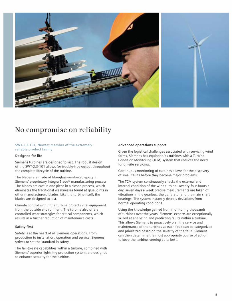
No compromise on reliability
Advanced operations support
Given the logistical challenges associated with servicing wind farms, Siemens has equipped its turbines with a Turbine Condition Monitoring (TCM) system that reduces the need for on-site servicing.
Continuous monitoring of turbines allows for the discovery of small faults before they become major problems.
The TCM system continuously checks the external and internal condition of the wind turbine. Twenty-four hours a day, seven days a week precise measurements are taken of vibrations in the gearbox, the generator and the main shaft bearings. The system instantly detects deviations from normal operating conditions.
Using the knowledge gained from monitoring thousands of turbines over the years, Siemens’ experts are exceptionally skilled at analyzing and predicting faults within a turbine. This allows Siemens to proactively plan the service and maintenance of the turbines as each fault can be categorized and prioritized based on the severity of the fault. Siemens can then determine the most appropriate course of action to keep the turbine running at its best.
5
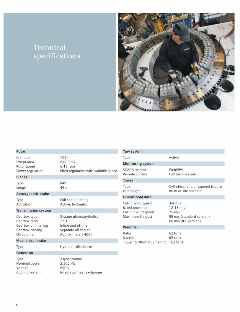
Yaw system
Type Active
Monitoring system
SCADA system WebWPSRemote control Full turbine control
Tower
Type Cylindrical and/or tapered tubularHub height 80 m or site-specific
Operational data
Cut-in wind speed 3-4 m/sRated power at 12-13 m/sCut-out wind speed 25 m/sMaximum 3 s gust 55 m/s (standard version) 60 m/s (IEC version)
Weights
Rotor 62 tonsNacelle 82 tonsTower for 80-m hub height 162 tons
Rotor
Diameter 101 mSwept area 8,000 m2Rotor speed 6-16 rpmPower regulation Pitch regulation with variable speed
Blades
Type B49Length 49 m
Aerodynamic brake
Type Full-span pitchingActivation Active, hydraulic
Transmission system
Gearbox type 3-stage planetary/helical Gearbox ratio 1:91Gearbox oil filtering Inline and offlineGearbox cooling Separate oil coolerOil volume Approximately 400 l
Mechanical brake
Type Hydraulic disc brake
Generator
Type AsynchronousNominal power 2,300 kWVoltage 690 VCooling system Integrated heat exchanger
Technical specifications
6
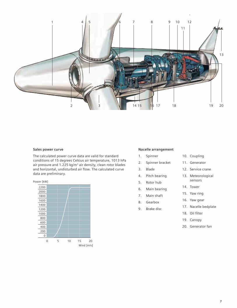
Sales power curve
The calculated power curve data are valid for standard conditions of 15 degrees Celsius air temperature, 1013 hPa air pressure and 1.225 kg/m3 air density, clean rotor blades and horizontal, undisturbed air flow. The calculated curve data are preliminary.
Nacelle arrangement
1. Spinner
2. Spinner bracket
3. Blade
4. Pitch bearing
5. Rotor hub
6. Main bearing
7. Main shaft
8. Gearbox
9. Brake disc
10. Coupling
11. Generator
12. Service crane
13. Meteorological sensors
14. Tower
15. Yaw ring
16. Yaw gear
17. Nacelle bedplate
18. Oil filter
19. Canopy
20. Generator fan
0 5 10 15 20
Power [kW]
Wind [m/s]
1
2 3
13
1615 18 19
4 5 6 7 8 9 1210
11
1714 20
2200
2000
1800
1600
1400
1200
1000
800
600
400
200
0
7

www.siemens.com/energy
Published by and copyright © 2009:Siemens AGEnergy SectorFreyeslebenstrasse 191058 Erlangen, Germany
Siemens AGSiemens Wind Power A/SBorupvej 167330 Brande, Denmarkwww.siemens.com/wind
For more information, please contact our Customer Support Center.Phone: +49 180 524 70 00Fax: +49 180 524 24 71(Charges depending on provider)E-mail: [email protected]
Renewable Energy DivisionOrder No. E50001-W310-A121-X-4A00Printed in GermanyDispo 34804, c4bs No. 7491fb 2225 WS 10095.
Printed on elementary chlorine-free bleached paper.
All rights reserved. Trademarks mentioned in this document are the property of Siemens AG, its affiliates, or their respective owners.
Subject to change without prior notice. The information in this document contains general descriptions of the technical options available, which may not apply in all cases. The required technical options should therefore be specified in the contract.