k eynote address: risk concepts for optimal hydrocarbon ...€¦ · hydrocarbon production o. t....
TRANSCRIPT

hydrocarbon production
O. T. Gudmestad Faculty of Science and Technology, University of Stavanger, Norway
Abstract
In order to ensure optimal production from hydrocarbon reserves, it is necessary to see to that risks in the production process are managed. This relate to limit the probability for production standstill and to limit the consequences of a production standstill. We emphasise on the causes of a production stop which are technical and which also relate to human behavior as well as sabotage and other unwanted incidents. Further, we discuss the consequences of a production stop which could be unexpected expenses and production delays caused by a need to perform maintenance. Other consequences could be safety and environmental related and could cause safety hazards and environmental damages. In order to manage the risk, we point to the needs for risk analysis which could be qualitative or quantitative. Thus, risks can be identified and risk mitigation efforts can be identified and implemented. We also discuss the benefits to an operating company and to the authorities of implementing a risk based scheme for securing the optimum production from a hydrocarbon province. Throughout the paper we refer to management of seismic risk and mitigation measures to manage the seismic risk by reducing the probability of severe consequences associated with seismic events. Keywords: risks, probability, consequences, QRA, international standards, seismic events, risk mitigation.
1 Introduction
Risks during production of oil and gas resources could be envisaged as the multiplication of the probability for production problem and the consequences of
Petroleum and Mineral Resources 1
www.witpress.com, ISSN 1743-3533 (on-line) WIT Transactions on Engineering Sciences, Vol 81, © 201 WIT Press2
doi:10.2495/PMR120011
K eynote address: risk concepts for optimal

the problem. In some cases the consequences can be huge to personnel and the environment and large assets can be lost. A production standstill will also represent a large loss of values. The causes of an undesirable event can be the physical environment (for example strong winds or seismicity), technical errors or wrong actions taken by humans and even by sabotage or other unwanted incidents. The causes have certain probabilities that should be reduced to acceptable levels. The consequences of an undesirable event will as a minimum be unexpected expenses and production delays caused by the need to perform maintenance. Risk analysis which could be qualitative or quantitative can be used to identify potential causes for failures and evaluate the potential consequences of these (see Figure 1) [1]. Thereafter, risk mitigation efforts can be identified and implemented. Such mitigation measures are, for example, proper inspection strategies, proper maintenance, implementation of automatic safety valves and other types of safety related equipment.
Figure 1: Risk estimation matrix for identification of unacceptable risk. The red area represents the unacceptable risk while the yellow area represents a region where the risk should be reduced to a level as low as reasonably practical (ALARP). Note that this figure only relates to personnel and assets and not to environmental damage. A similar figure can be developed for the clean environment where the toxicity level of pollutants will influence on the risk and the acceptable level of a release.
2 State of art with respect to risk management
In any efforts to manage risk, the key tasks are to set acceptance criteria, identify the risk and carry out mitigating measures. The acceptance criteria will have to
<10-6 10-6 - 10-4 10-4 - 10-2 10-2 - 1 > 1
10-7 10-5 10-3 10-1 10
People AssetsExtremely unlikely
Very unlikely Unlikely Probable Frequent
A B C D E
Minor injury Minor damage 1 A1 B1 C1 D1 E1
Loss time accident Damage 2 A2 B2 C2 D2 E2
Single or few serious injuries
Severe damage 3 A3 B3 C3 D3 E3
Single or few fatalities
Major damage 4 A4 B4 C4 D4 E4
Many fatalities (5 or more)
Catastrophic damage
5 A5 B5 C5 D5 E5
Increasing Likelihood >
Increasing Likelihood (Upper and Lower Values) >
Increasing Likelihood (Median Values) >
< I
ncre
asin
g Se
veri
ty
2 Petroleum and Mineral Resources
www.witpress.com, ISSN 1743-3533 (on-line) WIT Transactions on Engineering Sciences, Vol 81, © 201 WIT Press2
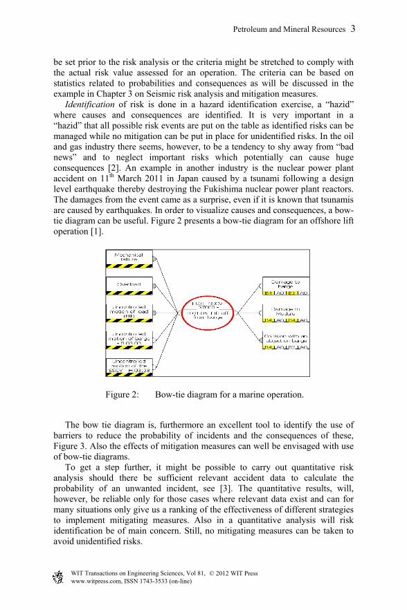
be set prior to the risk analysis or the criteria might be stretched to comply with the actual risk value assessed for an operation. The criteria can be based on statistics related to probabilities and consequences as will be discussed in the example in Chapter 3 on Seismic risk analysis and mitigation measures. Identification of risk is done in a hazard identification exercise, a “hazid” where causes and consequences are identified. It is very important in a “hazid” that all possible risk events are put on the table as identified risks can be managed while no mitigation can be put in place for unidentified risks. In the oil and gas industry there seems, however, to be a tendency to shy away from “bad news” and to neglect important risks which potentially can cause huge consequences [2]. An example in another industry is the nuclear power plant accident on 11th March 2011 in Japan caused by a tsunami following a design level earthquake thereby destroying the Fukishima nuclear power plant reactors. The damages from the event came as a surprise, even if it is known that tsunamis are caused by earthquakes. In order to visualize causes and consequences, a bow-tie diagram can be useful. Figure 2 presents a bow-tie diagram for an offshore lift operation [1].
Figure 2: Bow-tie diagram for a marine operation.
The bow tie diagram is, furthermore an excellent tool to identify the use of barriers to reduce the probability of incidents and the consequences of these, Figure 3. Also the effects of mitigation measures can well be envisaged with use of bow-tie diagrams. To get a step further, it might be possible to carry out quantitative risk analysis should there be sufficient relevant accident data to calculate the probability of an unwanted incident, see [3]. The quantitative results, will, however, be reliable only for those cases where relevant data exist and can for many situations only give us a ranking of the effectiveness of different strategies to implement mitigating measures. Also in a quantitative analysis will risk identification be of main concern. Still, no mitigating measures can be taken to avoid unidentified risks.
Petroleum and Mineral Resources 3
www.witpress.com, ISSN 1743-3533 (on-line) WIT Transactions on Engineering Sciences, Vol 81, © 201 WIT Press2
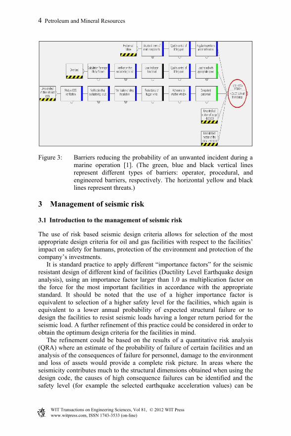
Figure 3: Barriers reducing the probability of an unwanted incident during a marine operation [1]. (The green, blue and black vertical lines represent different types of barriers: operator, procedural, and engineered barriers, respectively. The horizontal yellow and black lines represent threats.)
3 Management of seismic risk
3.1 Introduction to the management of seismic risk
The use of risk based seismic design criteria allows for selection of the most appropriate design criteria for oil and gas facilities with respect to the facilities’ impact on safety for humans, protection of the environment and protection of the company’s investments. It is standard practice to apply different “importance factors” for the seismic resistant design of different kind of facilities (Ductility Level Earthquake design analysis), using an importance factor larger than 1.0 as multiplication factor on the force for the most important facilities in accordance with the appropriate standard. It should be noted that the use of a higher importance factor is equivalent to selection of a higher safety level for the facilities, which again is equivalent to a lower annual probability of expected structural failure or to design the facilities to resist seismic loads having a longer return period for the seismic load. A further refinement of this practice could be considered in order to obtain the optimum design criteria for the facilities in mind. The refinement could be based on the results of a quantitative risk analysis (QRA) where an estimate of the probability of failure of certain facilities and an analysis of the consequences of failure for personnel, damage to the environment and loss of assets would provide a complete risk picture. In areas where the seismicity contributes much to the structural dimensions obtained when using the design code, the causes of high consequence failures can be identified and the safety level (for example the selected earthquake acceleration values) can be
4 Petroleum and Mineral Resources
www.witpress.com, ISSN 1743-3533 (on-line) WIT Transactions on Engineering Sciences, Vol 81, © 201 WIT Press2
increased for facilities that could cause high consequence failures, in order to reduce the total risk of damage to an acceptable level. Such facilities could be process facilities in the oil and gas sector, LPG tanks, toxic storage tanks etc., which possibly could cause unacceptable risk to nearby settlements or could cause unacceptable environmental damage. Alternatively, the distance between the facilities or to nearby settlements could be increased or nearby facilities could be strengthened to withstand explosion or fire loads. Similar consequence mitigation efforts could be implemented to contain environmental pollutants.
3.2 Selection of codes (standards) for the seismic resistant design of onshore facilities and offshore facilities
The laws and regulations in the country where a development is taking place determine the selection of codes and standards. In Norway the Petroleum Safety Authority (PSA) is the governing body for all offshore developments. PSA refers as much as possible to Norwegian Standards for the construction industry and to industry standards (the “NORSOK” standards) that have been developed by the oil industry in close cooperation with the PSA. For offshore structures, particular reference should be made to NORSOK Standards N-001 to N-004 (Standards Norway, Latest editions [4]). The N-003 standard does, for example, include recommendations as to earthquake resistant design of offshore platforms. The rules and regulations of PSA have been further developed to comply with the standards of the International Organization for Standardization (ISO) and the approach suggested in the latest ISO codes [5] is adapted, although selection of the safety level is decided at the national level. Norwegian specialists have prepared national seismic hazard map [6]. For onshore facilities, the standards developed by the European Committee for Standardization (CEN) do apply to Norway and these have gradually been adapted. As to earthquake resistant design, reference is made to Eurocode 8 [7] and to the Standards Norway [8]. The latest document is a translation of the Eurocode with a Norwegian Annex. Having the general standards of the country in mind, an operating company can select stricter criteria (higher safety level) should health, safety or environmental concerns (HSE-concerns) require so. For a company working in the international environment, the international standards prepared by ISO and CEN will normally constitute minimum requirements to the design. These are internationally gradually replacing the different US codes which often have been used, such as the International Building Code [9], formerly the Uniform Building Code) and other American National Standards (such as, for example, ANSI/ ASCE 7-05 [10]).
3.3 The safety principles of the ISO standard [5] for offshore structures
This standard presents a two level design procedure; design checks are to be made for the Serviceability Level Earthquake (SLE) and for the Ductility Level
Petroleum and Mineral Resources 5
www.witpress.com, ISSN 1743-3533 (on-line) WIT Transactions on Engineering Sciences, Vol 81, © 201 WIT Press2
Earthquake (DLE). The SLE criteria should lead to a design that will meet the DLE criteria with minimum of changes:
- SLE: little or no damage accepted during frequent earthquakes. - DLE: low probability of exceedance. Considerable damage accepted,
while collapse shall be avoided.
For a structure we determine the Seismic Risk Category, SCR that is used to determine how the seismic design is carried out, depending on the exposure level (L) and the site seismic zone. SLE and DLE return periods depend on the “exposure level”. A structure’s exposure level, L, depends on the criticality of the structure (see Table 1).
Table 1: Safety categories for structures, i.e. with different exposure levels (L) for structures according to the ISO Offshore ISO Standard [5].
Life safety category High consequence of failure
Medium consequence of failure
Low consequence of failure
Manned – Not evacuated L 1 L 1 L 1 Manned - evacuated L 1 L 2 L 2 Unmanned L 1 L 2 L 3
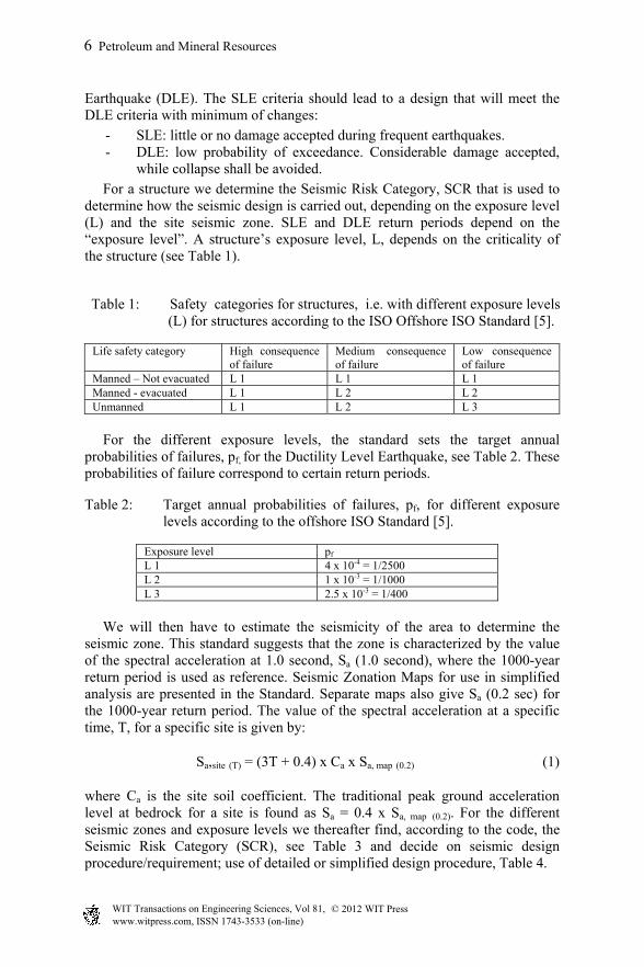
For the different exposure levels, the standard sets the target annual probabilities of failures, pf, for the Ductility Level Earthquake, see Table 2. These probabilities of failure correspond to certain return periods.
Table 2: Target annual probabilities of failures, pf, for different exposure levels according to the offshore ISO Standard [5].
Exposure level pf L 1 4 x 10-4 = 1/2500 L 2 1 x 10-3 = 1/1000 L 3 2.5 x 10-3 = 1/400
We will then have to estimate the seismicity of the area to determine the seismic zone. This standard suggests that the zone is characterized by the value of the spectral acceleration at 1.0 second, Sa (1.0 second), where the 1000-year return period is used as reference. Seismic Zonation Maps for use in simplified analysis are presented in the Standard. Separate maps also give Sa (0.2 sec) for the 1000-year return period. The value of the spectral acceleration at a specific time, T, for a specific site is given by:
Sa,site (T) = (3T + 0.4) x Ca x Sa, map (0.2) (1)
where Ca is the site soil coefficient. The traditional peak ground acceleration level at bedrock for a site is found as Sa = 0.4 x Sa, map (0.2). For the different seismic zones and exposure levels we thereafter find, according to the code, the Seismic Risk Category (SCR), see Table 3 and decide on seismic design procedure/requirement; use of detailed or simplified design procedure, Table 4.
6 Petroleum and Mineral Resources
www.witpress.com, ISSN 1743-3533 (on-line) WIT Transactions on Engineering Sciences, Vol 81, © 201 WIT Press2

Table 3: Seismic risk category according to Table 11.2-3 of the ISO Standard.
Table 4: Seismic design requirements according to Table 12.1-1 of ISO.
This ISO standard thus puts forward a semi-probabilistic approach to the design, prescribing a minimum safety level to be applied for the design of offshore structures.
3.4 The use of quantitative risk analysis (QRA) in the design of onshore facilities
3.4.1 Seismic design criteria for onshore facilities The design of onshore facilities is normally undertaken by determining the horizontal base shear force. This force is dependent upon the following parameters:
- Design base acceleration determined from seismic hazard analysis. - Response coefficient of the building to the load, taking into account the
dynamics of the building and the soil dynamic amplification effects. - Importance factor of the building. - Behavioral factor of the building as determined by the building’s structural
system. - Weight of the building.
Petroleum and Mineral Resources 7
www.witpress.com, ISSN 1743-3533 (on-line) WIT Transactions on Engineering Sciences, Vol 81, © 201 WIT Press2

Through this approach, the safety level is inherent in the
- selection of the return period for the design base acceleration; - importance factor of the building.
The CEN code (the code of the European Union) applicable for the earthquake resistant design of buildings (Eurocode 8 [7]) recommends a return period of 475 years for ductile design, i.e. a design where collapse is avoided. The different member countries of the European Union select the safety level, depending upon the safety level specified in the laws of the countries. The importance factor reflecting the importance category of the building should be selected as depending upon the variability in the seismic hazard at the site. The importance factors recommended in Eurocode 8 and the factors recommended in the Norwegian code (Table 5) reflect the differences in earthquake variability between Southern European countries and in Norway.
Table 5: Importance factors for seismic resistant design of buildings.
3.4.2 Application of QRA for the establishment of risk based seismic design criteria
For a specific facility, we suggest to select the effective design acceleration (i.e. the design base acceleration multiplied with the importance factor) on the basis of a risk analysis where we compare the risk to personnel, to the environment, to assets and to nearby facilities with acceptance criteria set by the operating company. These acceptance criteria could be criteria for safeguarding of the facilities or the environment and for the personnel. Note that the acceptance criteria as a minimum must satisfy the requirements and laws of the country in which the facilities are installed. For a selected part of the facilities, for example a building, a tank, or a gas centre, the probability of failure, pf, is determined through the selection of the effective design acceleration. Furthermore, the consequences of failure to nearby facilities, the environment or the personnel (including personnel living in nearby settlements) are dependent upon the distance of the selected part to the nearby facility and the structural strength of the nearby facility. For a situation with a prevailing wind direction we obtain, for example, “risk contours” as shown in Figure 4 (possibly resulting in consequences that could cause failure of nearby facilities, like for example when the gas ratio in a gas cloud could cause explosion of nearby facilities, etc.). Note that in the case of larger amounts of gas release, the scales in Figure 4 may be increased one or several orders of magnitude.
8 Petroleum and Mineral Resources
www.witpress.com, ISSN 1743-3533 (on-line) WIT Transactions on Engineering Sciences, Vol 81, © 201 WIT Press2
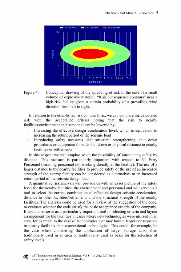
Figure 4: Conceptual drawing of the spreading of risk in the case of a small volume of explosive material. “Risk consequence contours” near a high-risk facility given a certain probability of a prevailing wind direction from left to right.
In relation to the established risk contour lines, we can compare the calculated risk with the acceptance criteria noting that the risk to nearby facilities/environment and personnel can be lowered by:
- Increasing the effective design acceleration level, which is equivalent to increasing the return period of the seismic load
- Introducing safety measures like: structural strengthening, shut down procedures or equipment for safe shut down or physical distance to nearby facilities or settlements
In this respect we will emphasise on the possibility of introducing safety by distance. This measure is particularly important with respect to 3rd Party Personnel (meaning personnel not working directly at the facility). The use of a larger distance to the nearby facilities to provide safety or the use of an increased strength of the nearby facility can be considered as alternatives to an increased return period of the seismic design load. A quantitative risk analysis will provide us with an exact picture of the safety level for the nearby facilities, the environment and personnel and will serve us a tool to select the correct combination of effective design seismic acceleration, distance to other facilities/settlements and the structural strength of the nearby facilities. The analysis could be used for a review of the suggestion of the code, to evaluate whether the code satisfy the basic acceptance criteria of the company. It could also serve as a particularly important tool in selecting criteria and layout arrangement for the facilities in cases where new technologies were utilized in an area, for example in the case of technologies that may have a larger consequence to nearby facilities than conventional technologies. This could, for example, be the case when considering the application of larger storage tanks than traditionally used in an area or traditionally used as basis for the selection of safety levels.
Petroleum and Mineral Resources 9
www.witpress.com, ISSN 1743-3533 (on-line) WIT Transactions on Engineering Sciences, Vol 81, © 201 WIT Press2

It should be noted that the design of major facilities in the oil and gas industry always should be based on a site specific hazard analysis, determining the seismic hazard, and a site specific analysis of the geotechnical data (soils data) at the site.
3.4.3 Application of QRA for the establishment of risk based seismic design criteria for gas systems
The alternative of using shut down systems can be particularly useful in case of gas facilities/gas pipelines. The acceptable inventory of gas in a pipeline system could be identified as a function of the seismic hazard. Then, optimization can be carried out as regarding the most optimum way to provide the acceptable safety level, either by introducing a lower probability of failure (increasing the return period of the seismic design load) or by decreasing the gas inventory (for example by increasing the number of shut down values that are reacting to a certain earthquake acceleration level).
3.5 Examples
For onshore facilities in Norway, reference has for design purposes in the past often been given to different versions of the Uniform Building Code (the latest version was issued by ICC [9]). Site-specific seismic risk analysis have been carried out to determine the acceleration levels and the safety level has been set to a DLE level with an annual probability of exceedance of 10-4. For some specific facilities (like the Mongstad oil refinery and the Snøhvit LNG plant) in the vicinity of areas with high population, the risk to personnel living outside the facilities was considered through quantitative risk analysis in order to satisfy the requirement of obtaining a FAR value of around one for those living outside the facilities (meaning that the fatality ratio should not be more than 1 in the case of 108 exposed hours).
3.6 Conclusions related to seismic design criteria
The safety requirements of the different international design codes in relation to earthquake resistant design have recently been reviewed. The ISO code for offshore structures [5] and the new Eurocode 8 for onshore buildings [7] represent well balanced codes. It is suggested, however, that a quantitative risk analysis could be well suited to confirm that the safety obtained through the use of the codes, is adequate for the facilities being designed. This relates in particular to facilities in the oil and gas industry as these facilities often contain large amounts of highly flammable and toxic materials.
4 Application of the learnings from seismic design to other areas of the society
The approach outlined for management of seismic risk can be applied in other industries and in particular for the oil and gas industry. The approach consists of:
10 Petroleum and Mineral Resources
www.witpress.com, ISSN 1743-3533 (on-line) WIT Transactions on Engineering Sciences, Vol 81, © 201 WIT Press2

- Setting the design criteria following a risk analysis where high risk activities be designed for lower probability of occurrence and/or lower consequences than for low risk activities
- Selection of proper state of art international codes or recommended practice for the design, should the national code be goal setting and be lacking design suggestions.
The risk analysis as prescribed above could be qualitative in case few data exist to quantify probabilities and/or consequences. In case sufficient relevant data exists, the analysis could be quantitative (QRA), leading to an assumed realistic ranking of different options for design. The design criteria set must be quantitative with respect to safety level for the design in order to the user to be able to select design values for important parameters. In some instances, the design criteria could be probabilistic, leading to the requirement for a low (and specified) probability of exceedance of the safety level selected. As a matter of fact, modern design codes are often semi probabilistic where the selection of safety factors (action and resistance factors) is based on analysis of the probability of exceedance. The action is defined with a certain probability of exceedance (for example based on a wind speed with an annual probability of exceedance of 0.02 (50 year return period). The action value calculated must be multiplied with an action factor to account for the uncertainty in the estimate. The factored action value must be less that the factored resistance value: the resistance value could be the yield strength of steel with a certain fraction of exceedance (for example 0.02) divided with a resistance factor to account for uncertainties, equation (2):
γl L < R/γr (2)
It must be realized that no risk analysis is helpful in case the risk identification, the hazard identification, is suppressed by management requesting a successful project without any threats. The “devil’s advocate” should be engaged to identify all operations that could represent non acceptable risk and where risk mitigation measures must be incorporated, potentially in form of procedural or other types of barriers that will reduce the risk to an acceptable level.
5 Conclusions and recommendations
It is concluded that risk analysis should be carried out in engineering projects. The following activities have to be carried out:
- Set acceptance criteria for risk, by selecting appropriate standards or possibly by carrying out quantitative risk analysis of generalized events.
- Identify the risk in the activity. - Evaluate potential hazards that could lead to undesired events the
probability issue). - Evaluate potential consequences of undesired events (the consequence
issue).
Petroleum and Mineral Resources 11
www.witpress.com, ISSN 1743-3533 (on-line) WIT Transactions on Engineering Sciences, Vol 81, © 201 WIT Press2

- Implement risk mitigation measures when the risk exceeds the acceptance criteria.
- When sufficient relevant data are available, the risk analysis could be quantitative. Then we could rank the different mitigation measures and select the most appropriate measure.
For seismic design, risk analysis of new projects should follow international standards. For ongoing activities, risk analysis might identify the needs for mitigating measures, such as the needs for introduction of additional safety valves or instrumentation to allow for shut down in case of emergency. For a general evaluation of the risk in the oil and gas sector, reference is also made to Bercha [11].
Acknowledgements
The author acknowledges a long standing cooperation with Dr Vladimir Trbojevic of Risk Support, London on risk analysis in marine and construction activities and with Frank Bercha of Bercha Group, Calgary, Canada.
References
[1] Trbojevic, V. M. and O. T. Gudmestad; “Risk analysis of marine operations in Arctic waters”, Proc. POAC, POAC paper 2009-088, Luleå, Sweden, June 2009.
[2] Gudmestad, O. T.: “Treatment of “Bad news” in a project”, Proceedings of the 24th Int. Congress on Condition Monitoring and diagnostics Engineering management, ISBN 09541307-2-2, pp. 1035-1041, Stavanger, June 2011.
[3] Aven, T. and Vinnem, J.-E.: Risk Management with Applications from the Offshore Petroleum Industry, Series: Springer Series in Reliability Engineering, 2007.
[4] Standards Norway: NORSOK Standard N-003: “Actions and Action Effects”, Rev 2, 2007. Standards Norway, Oslo. (http://www.standard.no /en/Sectors/Petroleum/NORSOK-Standard-Categories/N-Structural/).
[5] International Organization for Standardization (ISO): ISO 19901-2 “Petroleum and natural gas industries - Specific requirements for offshore structures - Part 2: Seismic design procedures and criteria”, ISO 19901-2:2004, ISO, Geneva, 2005.
[6] NFR/Norsar: “Seismic Zonation for Norway”, Norwegian Council for Building Standardization, NBR, Oslo, 1998.
[7] European Committee for Standardization (CEN): “Eurocode 8: Design of structures for earthquake resistance”, CEN Brussels, 2008.
[8] Standards Norway: NS-EN 1998-1:2004+NA: Prosjektering av kon-struksjoner for seismisk påvirkning - Del 1: Allmenne regler, seismiske laster og regler for bygninger, with Norwegian annex, Standards Norway, 2008.
12 Petroleum and Mineral Resources
www.witpress.com, ISSN 1743-3533 (on-line) WIT Transactions on Engineering Sciences, Vol 81, © 201 WIT Press2

[9] International Code Council, (ICC): “International Building Code”, Virginia, USA, 2012.
[10] American National Standards Institute, (ANSI): “American National Standard, Minimum design loads for buildings and other structures”, ANSI/ ASCE 7-05, New York, USA, 2006.
[11] Bercha, F. D.: Risk Analysis, Methods and Applications, Universal Publishers Inc., 2012.
Petroleum and Mineral Resources 13
www.witpress.com, ISSN 1743-3533 (on-line) WIT Transactions on Engineering Sciences, Vol 81, © 201 WIT Press2