k aps mini arem57u en - provu communications · page 3 2 product description the arem 57u 1) reader...
TRANSCRIPT

AREM 57U
APS mini reader module in IPDP SLIM panels
User’s guide
®
© 2004 – 2011, TECH FASS s.r.o., Plavecka 503, 252 42 Jesenice, Czech Republic, www.techfass.cz, [email protected] (Date of release: 02-11-2011, valid for FW version 4.14)

All brand or product names are or may be trademarks of, and are used to identify products and services of, their respective owners.
1 Content
1 Content ....................................................................................................................... 2 2 Product Description .................................................................................................... 3 3 Technical parameters ................................................................................................. 3
3.1 Product version .................................................................................................... 3 3.2 Technical features ................................................................................................ 4
3.3 Mechanical design ............................................................................................... 4 4 Installation .................................................................................................................. 5
4.1 Connectors description ........................................................................................ 5 4.2 Wiring description ................................................................................................ 5 4.3 Reader module connection .................................................................................. 6
4.4 LED Indicators ..................................................................................................... 6 4.5 Installation instructions ......................................................................................... 6 4.6 Mounting and removal of the module ................................................................... 6
5 Setting parameters of the reader module .................................................................... 7 5.1 Configurable parameters ...................................................................................... 7
5.2 Reader module parameters setting ...................................................................... 7 6 Reader module functioning ......................................................................................... 7
6.1 “Door Open” function description ......................................................................... 8 6.2 Function permanent door lock release according to a time schedule ................... 8 6.3 Standard operating modes ................................................................................... 8
6.4 Read ID media format .......................................................................................... 8 6.5 Programming mode ............................................................................................. 9 6.6 Access rights ..................................................................................................... 13
7 Useful links ............................................................................................................... 13

Page 3
2 Product Description
The AREM 57U 1) reader modules (125 kHz readers with an embedded single door controller) are designed for connection to the RS 485 bus of the APS mini access control system. It is possible to connect up to 32 reader modules to a single line of the APS mini system. In effect the number of lines is not limited.
The modules are supplied as a part of IPDP SLIM panels (design Urmet). The product is distributed by ALPHATECH TECHNOLOGIES s.r.o. company.
1) Commercial designation of available versions is described in table 1.
3 Technical parameters
3.1 Product version
Pro
duct
ver
sion
Product designation Catalogue number
Module features 2)
TF
EM
HID
AREM 57U - TF 52457200 AREM 57U - EM 52457201
Table 1: Product version
2) TF – TECHFASS factory ID media reading; EM – EM Marin ID media reading; HID –HID Proximity ID media reading
Pic. 1: AREM 57U

Page 4
3.2 Technical features Te
chni
cal f
eatu
res Supply voltage 8 ÷ 18 VDC
Current demand Typical 80 mA Maximal 90 mA (8 V)
Version with keypad N/A ID technology, typical reading range
EM Marin 4 cm (with ISO card) HID Proximity 3 cm (with ISO card)
Real-time clock Yes
Memory Cards 748 ID, 2 programming cards Time schedules 64
Inputs N / A
Output Door lock
1x open collector 0V active – for connection to the REX device of the IPDP SLIM panel
Alarm N / A
Signalization 3x LED 1x PIEZO
Tamper protection N / A Communication interface RS 485 Alternative data output N / A
Table 2: Technical features
3.3 Mechanical design
Mec
hani
cal d
esig
n Weight 0,025 kg Operating temperature -25 ÷ 60 °C Humidity Max. 95%, non-condensing Housing IP 44 (built in the entry panel) Cable length 2x 0,4 m Color White Dimensions 21 x 85 x 21 mm
Table 3: Mechanical design
Page 5
4 Installation
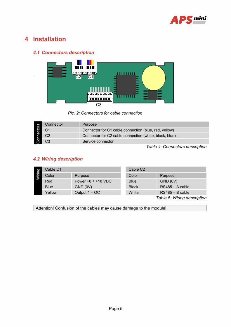
4.1 Connectors description
Con
nect
ors Connector Purpose
C1 Connector for C1 cable connection (blue, red, yellow) C2 Connector for C2 cable connection (white, black, blue) C3 Service connector
Table 4: Connectors description
4.2 Wiring description
Wiri
ng Cable C1 Cable C2
Color Purpose Color Purpose Red Power +8 ÷ +18 VDC Blue GND (0V) Blue GND (0V) Black RS485 – A cable Yellow Output 1 – OC White RS485 – B cable
Table 5: Wiring description
Attention! Confusion of the cables may cause damage to the module!
C1 C2
C3
Pic. 2: Connectors for cable connection

Page 6
4.3 Reader module connection
The C1 cable is standardly soldered to the panel PCB, which provides power supply and door lock control contact for the reader module. For connecting to a PC, the C2 cable must be used.
4.4 LED Indicators
LED
indi
cato
rs
Red Continuously lit Online operating mode via RS 485 Flashing with 4 s period Offline operating mode Fast switching with green Address setting mode
Yellow Continuously lit Programming mode Flashing Indicating door lock release
Green ID media reading Table 7: LED indicators
4.5 Installation instructions
The reader module uses passive RF/ID technology, which is sensitive to RF noise sources. Noise sources are generally of two types: radiating or conducting.
Conducted noise enters the reader via wires from the power supply or the host. Sometimes, switching power supplies generate enough noise to cause reader malfunction, it is recommended to use linear system power supplies.
Radiated noise is transmitted through the air. It can be caused by computer monitors or other electrical equipment generating electromagnetic fields.
Consequently, a short distance between the reader modules themselves can cause reading malfunctions – for correct operation it is necessary to keep a minimum distance of 50 cm. Various metallic constructions may have a negative influence on this distance; if there are any doubts, it is recommended to perform a practical test before final mounting.
Nearby metal surfaces may cause a decrease in reading distance and speed. This is caused by the combined effects of parasitic capacitance and conductance.
4.6 Mounting and removal of the module
The module is supplied built-in in the IPDP SLIM panel, where it occupies space of a single push button space in a predefined position. For manipulation with the devices please follow the instructions in the user’s guide to the IPDP SLIM panel.
Page 7
5 Setting parameters of the reader module
5.1 Configurable parameters
Con
figur
able
par
amet
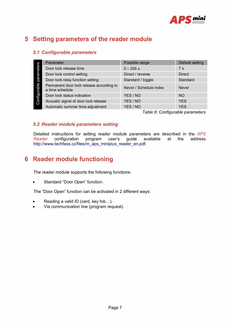
ers Parameter Possible range Default setting
Door lock release time 0 255 s 7 s Door lock control setting Direct / reverse Direct Door lock relay function setting Standard / toggle Standard Permanent door lock release according to a time schedule Never / Schedule index Never
Door lock status indication YES / NO NO Acoustic signal of door lock release YES / NO YES Automatic summer time adjustment YES / NO YES
Table 8: Configurable parameters
5.2 Reader module parameters setting
Detailed instructions for setting reader module parameters are described in the APS Reader configuration program user’s guide available at the address http://www.techfass.cz/files/m_aps_miniplus_reader_en.pdf.
6 Reader module functioning
The reader module supports the following functions:
Standard “Door Open” function.
The “Door Open” function can be activated in 2 different ways:
Reading a valid ID (card, key fob…). Via communication line (program request).
Page 8
6.1 “Door Open” function description
In case the standard function of the door lock relay is set, the door lock is released and the beeper activated (when not disabled) when the “Door Open“ function is activated. Both outputs stay active until the preset door lock release time has elapsed - see Tab. 8.
In case the toggle function of the door lock relay is set, the door lock relay status is switched and the beeper is activated (when not disabled) when the “Door Open” function is activated. The beeper stays active until the preset door lock release time has elapsed - see Tab. 8. The door lock relay status remains unchanged until another “Door Open” function is activated.
Reading a programming card during door lock release will not cause the reader to enter the programming mode.
In case the standard function of the door lock relay is set, reading a valid card during door lock release resets the door lock release time.
6.2 Function permanent door lock release according to a time schedule
When the function is set, the door lock is permanently released when relevant time schedule is valid. Reading a valid ID is standardly announced via the communication line (in online operating mode).
The permanent door lock release function and the toggle function of the door lock relay are mutually exclusive.
6.3 Standard operating modes
The reader module can be in either online or offline operating mode. The module’s functionality is identical in both operating modes; the events archive is read from the reader module’s memory when the module goes online. When a programming card is read (while in either online or offline mode), the module goes into programming mode.
6.4 Read ID media format
6.4.1 EM Marin ID media format
The EM Marin ID media format can be changed into selected 24, 32 or 40 bits length of ID code. The default length is 40 bits. This setting is only used when unifying of the ID media codes length is required – in combined systems with WIEGAND output readers with a fixed WIEGAND data format IDs (more information in APS Reader user’s guide available at http://www.techfass.cz/files/m_aps_miniplus_reader_en.pdf).
6.4.2 HID Proximity ID media format
When working with HID Proximity technology ID media, the module operates with a code in a recognized 26 or 32 bit format, in other cases it uses all 45 bits of a media (45bit raw format). If a specific format of the HID Proximity IDs is required, it can be performed by setting up the user’s configuration of read IDs (more information in APS Reader user’s guide available at http://www.techfass.cz/files/m_aps_miniplus_reader_en.pdf).

Page 9
6.5 Programming mode
The module enters programming mode by reading one of the two programming cards (cards “+” and “-“). The programming mode cannot be entered while the module is in hardware address setting mode (for modules with HW address setting via the communication line). The module’s functionality in programming mode can be seen in pictures 5 a-d.
It is not possible to use time schedules when inserting cards in programming mode, therefore cards are always valid.
6.5.1 Inserting cards into the reader’s memory
Follow these steps for inserting cards into the reader module’s memory:
Step 1 Step 2 Step 3
Read the programming card for inserting: the reader goes into programming mode.
One by one, read the cards which are to be granted access.
About 15 seconds after inserting the last card the reader module goes back into standard operating mode.
Pic.5 a): Inserting cards
6.5.2 Deleting cards from the reader’s memory
For deleting the cards from the reader module’s memory use following steps:
Step 1 Step 2 Step 3
Read the programming card for deleting: the reader goes into programming mode.
One by one, read the cards which are to have their access revoked.
About 15 seconds after deleting the last card the reader module goes back into standard operating mode.
Pic.5 b): Deleting cards
Page 10
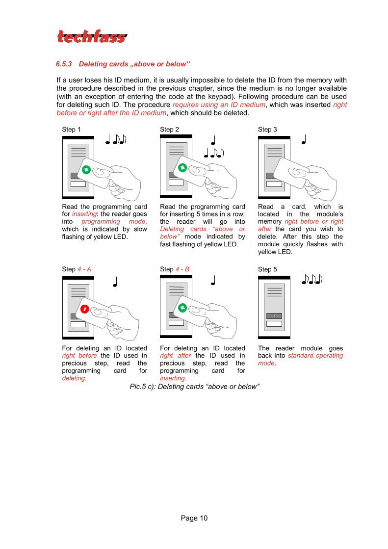
6.5.3 Deleting cards „above or below“
If a user loses his ID medium, it is usually impossible to delete the ID from the memory with the procedure described in the previous chapter, since the medium is no longer available (with an exception of entering the code at the keypad). Following procedure can be used for deleting such ID. The procedure requires using an ID medium, which was inserted right before or right after the ID medium, which should be deleted.
Step 1 Step 2 Step 3
Read the programming card for inserting: the reader goes into programming mode, which is indicated by slow flashing of yellow LED.
Read the programming card for inserting 5 times in a row; the reader will go into Deleting cards “above or below” mode indicated by fast flashing of yellow LED.
Read a card, which is located in the module’s memory right before or right after the card you wish to delete. After this step the module quickly flashes with yellow LED.
Step 4 - A Step 4 - B Step 5
For deleting an ID located right before the ID used in precious step, read the programming card for deleting.
For deleting an ID located right after the ID used in precious step, read the programming card for inserting.
The reader module goes back into standard operating mode.
Pic.5 c): Deleting cards “above or below”

Page 11
6.5.4 Deleting all cards from the reader’s memory
Follow these steps for deleting all cards from the reader module’s memory:
Step 1 Step 2 Step 3
Read the programming card for deleting: the reader goes into programming mode.
Read the programming card for deleting 5 times in a row; the reader will erase all cards from its memory.
The reader module goes back into standard operating mode.
Pic.5 d): Deleting all cards
6.5.5 Recommended method for access rights management (using prog. cards)
In case of managing access rights of plenty of users (using programming cards only), it is appropriate to establish a table, which summarizes operation with the reader module memory. All operations (adding and deleting cards) should be stored in the table. Following example shows correct usage of the programming cards and proper filing of the actions:
Inserting 5 new cards using the procedure from chapter 6.5.1 – Read + (inserting) programming card, read cards 1-5, after 15 s the programming mode is exited, create a table.
Pic.5 e): Table after inserting 5 cards
Card 3 gets lost – Delete it using the card 4, which is available, and using the procedure from chapter 6.5.3 – Read + (inserting) programming card, then 5x + (inserting) programming card again, then card 4, and finally – (deleting) programming card. Register the change in your table.
Pic.5 f): Deleting card 3 using the card 4, table after deleting card 3
position card 1 card 1 2 card 2 3 card 3 (lost) 4 card 4 (available) 5 card 5
position card 1 card 1 2 card 2 3 card 3 4 card 4 5 card 5
position card 1 card 1 2 card 2 3 card 3 4 card 4 5 card 5
5x
Page 12
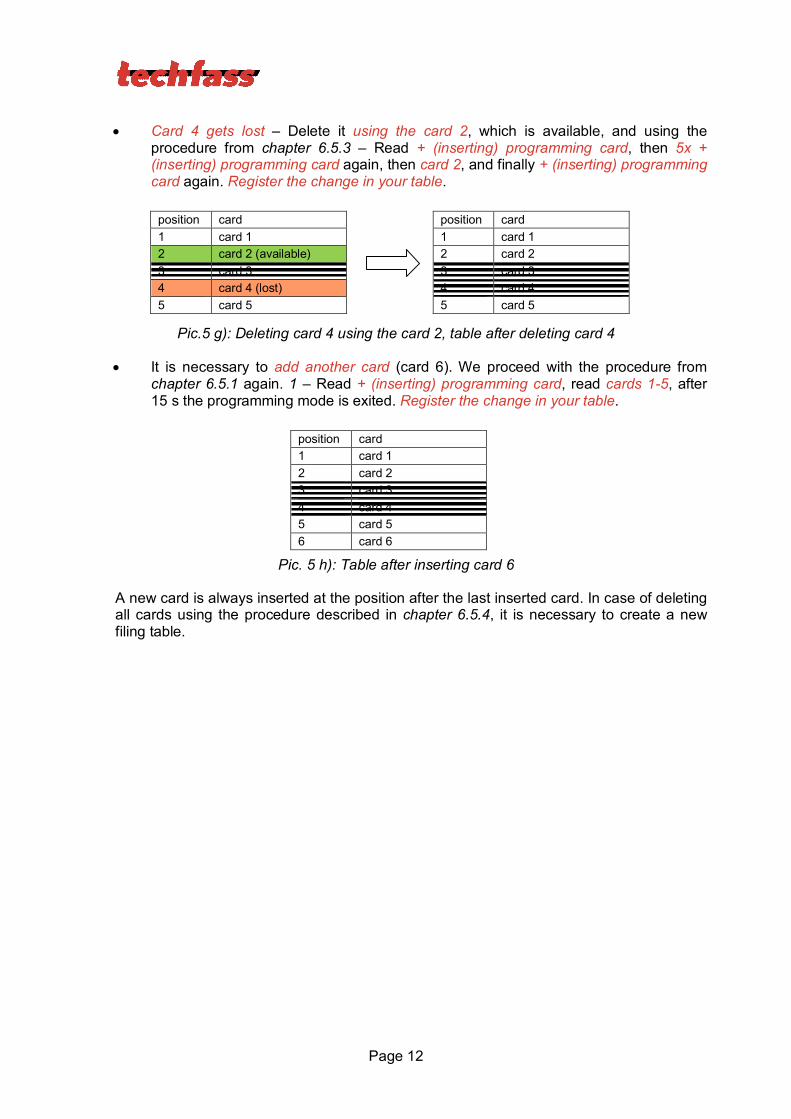
Card 4 gets lost – Delete it using the card 2, which is available, and using the procedure from chapter 6.5.3 – Read + (inserting) programming card, then 5x + (inserting) programming card again, then card 2, and finally + (inserting) programming card again. Register the change in your table.
Pic.5 g): Deleting card 4 using the card 2, table after deleting card 4
It is necessary to add another card (card 6). We proceed with the procedure from chapter 6.5.1 again. 1 – Read + (inserting) programming card, read cards 1-5, after 15 s the programming mode is exited. Register the change in your table.
Pic. 5 h): Table after inserting card 6
A new card is always inserted at the position after the last inserted card. In case of deleting all cards using the procedure described in chapter 6.5.4, it is necessary to create a new filing table.
position card 1 card 1 2 card 2 3 card 3 4 card 4 5 card 5 6 card 6
position card 1 card 1 2 card 2 (available) 3 card 3 4 card 4 (lost) 5 card 5
position card 1 card 1 2 card 2 3 card 3 4 card 4 5 card 5
Page 13
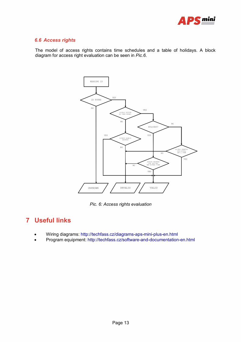
6.6 Access rights
The model of access rights contains time schedules and a table of holidays. A block diagram for access right evaluation can be seen in Pic.6.
Pic. 6: Access rights evaluation
7 Useful links
Wiring diagrams: http://techfass.cz/diagrams-aps-mini-plus-en.html Program equipment: http://techfass.cz/software-and-documentation-en.html
VALID UNKNOWN
ID FOUND
ACCESS DRIVEN BY TIME SCHED.
ACCESS ALWAYS GRANTED
HOLIDAY?
ACCESS GRANTED FOR HOLIDAY
AND ACTUAL TIME
ACCESS GRANTED FOR ACTUAL DAY & TIME
READING ID
YES
NO YES
NO
NO
YES
INVALID
YES
NO
NO
YES
NO
YES