jwst pathfinder telescope risk reduction cryo test … · jwst pathfinder telescope risk reduction...
TRANSCRIPT

JWST pathfinder telescope risk reduction cryo test program Gary W. Matthews
a, Thomas R. Scorse
a, John A. Spina
a, Darin M. Noël
a, Keith A. Havey Jr
a,
Jesse A. Hugueta, Tony L. Whitman
a, Conrad Wells
a, Chanda B. Walker
a, Sharon Lunt
a,
James B. Hadawayb,
Ritva Keski-Kuhab, Lee D. Feinberg
b, Mark F. Voyton
b, Juli A. Lander
c, James M. Marsh
c
aExelis Inc., a wholly owned subsidiary of Harris Corp. (United States),
bUniversity of Alabama
Huntsville, cNASA Goddard Space Flight Ctr. (United States)
ABSTRACT
In 2014, the Optical Ground Support Equipment was integrated into the large cryo vacuum chamber at Johnson Space
Center (JSC) and an initial Chamber Commissioning Test was completed. This insured that the support equipment was
ready for the three Pathfinder telescope cryo tests. The Pathfinder telescope which consists of two primary mirror
segment assemblies and the secondary mirror was delivered to JSC in February 2015 in support of this critical risk
reduction test program prior to the flight hardware. This paper will detail the Chamber Commissioning and first optical
test of the JWST Pathfinder telescope.
Keywords: JWST, Telescope, Alignment, Integration, Test
1. INTRODUCTION
The James Webb Space Telescope (Figure 1) is the successor to
the Hubble Space Telescope. JWST will operate in the infrared
region of the electromagnetic spectrum to allow the science
community to observe far red shifted stars and galaxies as they
were originally forming after the Big Bang 13.8 billion years
ago. The scientists call JWST the first light machine since it will
actually observe the first stars “turning on” and early galaxy
formation. Even though the light from these early stars and
galaxies was created billions of years ago, that light is just
getting to our solar system now. They are moving away from us
at nearly the speed of light Doppler-shifting the visible light into
the infrared. In order to image this phenomenon, the telescope
must also image in the infrared spectrum. This means that the
telescope and all the systems that create that image must be very
cold. That is why JWST operates at 40K. This extreme
temperature creates many challenges for the engineers and
scientists that are building and testing the observatory. This
paper will provide an overview of the Alignment, Integration,
and Test (AI&T) program and provide specific details on the
Pathfinder telescope integration that occurred in 2014.
2. ALIGNMENT, INTEGRATION, AND TEST
The AI&T phase of the program is fast approaching. But it has been in the planning stages since the inception of the
program. It was recognized very early that the integration and test would be critical in the successful execution of the
program. There are really two distinct aspects of JWST that are unique to the program – the optical configuration and
operating temperature. The optical configuration for JWST represents the first space-based telescope that is segmented
and deployable on orbit which provides a set of interesting challenges to be able to build an 18 segment primary mirror
on Earth with the assurance that once on-orbit in zero gravity, it can be aligned to create a monolithic-like optical
Figure 1: The James Webb Space Telescope in its fully
deployed configuration.
https://ntrs.nasa.gov/search.jsp?R=20150018095 2018-08-25T15:03:46+00:00Z

surface. The operating temperature is truly the biggest challenge for testing. In order to verify the performance, the
largest cryogenic environmental test system in the world has been created. Given the fact that it takes a month to cool
down and another two weeks to warm the system, a test configuration has been developed that will operate with the
accuracy and dependability to satisfy the verification program.
The initial phase of the program will be to build what is called the Optical Telescope Element (OTE). This is the 6.5m
telescope as shown in Figure 2. It is comprised of the large optical elements and the main structures that make up the
system. Once the telescope is completed, the Integrated Science Instrument Module (ISIM) shown in Figure 3 is aligned
and mated to the telescope. This major subsystem is called the OTIS which is comprised of the OTE and the ISIM.
.
Figure 2: The major components of the Optical Telescope Element are shown above.
Figure 3: The Integrated Science Instrument Module consists of the instrument assembly and the Integrated Electronics
compartment.

The final success of the AI&T portion of the program will be driven by careful planning and demonstrations prior to
building the flight telescope and observatory to insure that the program can stay on plan during this critical path phase of
the program
To aid in this very difficult task, a risk reduction Pathfinder Integration and Test program has been included in the plan
since the original JWST proposal submitted by Northrop Grumman.
3. THE PATHFINDER PROGRAM
The Pathfinder program has been a part of
JWST since the very beginning of the
program. The combined experience of the
NASA/contractor team placed a high value
of making the investment in a risk
reduction, alignment, integration and test
program. In essence, the Pathfinder
program has two distinct parts; the
telescope integration phase and the cryo
test phase. This paper focuses on the
alignment and integration phase of the
Pathfinder program. Paper SPIE 9575-3
discussed the integration of the three
mirrors onto the composite backplane
structure (Figure 4).
The two PMSA’s and the secondary mirror
are all flight spares that are fully
representative of the flight optics in every
way. It should be noted that only one of
the primary mirror segments are coated.
The other two mirrors are polished
Beryllium with no coating. For the
purposes of the risk reduction program,
this slight difference in reflectance is not
considered to be a problem for the test
equipment.
The test phase of the Pathfinder program is to check out all the
cryo test equipment against a representation of the flight
telescope. The Pathfinder telescope was shipped to the Johnson
Space Center in Houston and installed in the large cryo,
vacuum chamber. Over the past several years, the Apollo era
vacuum chamber has been transformed into a state-of-the-art
optical test system with specialized optical test equipment
inside the giant thermal shrouds that operate at less than 20K
using a 12.5KW Helium regeneration refrigeration system. The
vacuum chamber and the connected clean room are shown in
Figure 5.
The cryo test risk reduction program has four parts that will be
executed over a period of 18 months. These tests are designed
to add complexity as the confidence in the previous test is
gained. Each step adds modest complexity and as much as
possible, each test program can stand on its own merits. The
tests are as follows:
Secondary Mirror
Secondary Mirror Support Struts
Primary Mirror Segment Assemblies
Future location of Aft Optics Subsystem
Pathfinder Backplane
Figure 4: The Pathfinder telescope contains two; spare primary mirrors
segments assemblies (OMSA) and the spare secondary mirror assembly
(SMA). The flight aft optics assembly (AOS) will be installed after delivery to
JSC.
Figure 5: The JSC clean room will be used to stage the
Pathfinder and flight system into the large refurbished
cryo vacuum chamber.

Chamber Commissioning Test (CCT): The CCT is the initial cryo test of the Optical Ground Support
Equipment (OGSE) hardware and chamber system that will be used in the subsequent test program. It should be
noted, that some additional test hardware will be added as the test program proceeds but all the major elements
were present at the CCT test. The CCT was envisioned to check out the functionality of all the test hardware
prior to starting the formal hardware testing with the Pathfinder telescope. It also served as final cryo load test
of the OGSE hardware prior to introducing any critical optical hardware.
Optical Ground Support Equipment #1 (OGSE#1): OGSE#1 is the first test that uses the Pathfinder telescope.
This test program checks out the chamber dynamic control system, the center of curvature test system and the
photogrammetry system. During the test, the team will also load test the AOS interface where the flight
hardware will be placed for OGSE#2.
Optical Ground Support Equipment #2 (OGSE#2): The next step in complexity is to add the Aft Optics
Subsystem (AOS) to the Pathfinder telescope which allows the half pass and the pass and a half test to be
demonstrated. In addition to the AOS, the source plate will also be included in this test that illuminates the full
telescope system. In order to be able to understand the telescope performance, an instrument simulator called
the Beam Image Analyzer (BIA) was developed by NASA and included in the OGSE#2 test. By the end of
OGSE#2, the entire optical system test program will have been demonstrated.
Thermal Pathfinder (TPF): The TPF program is a unique test that simulates how the flight system will react as
the chamber temperatures are changed. Mirror simulators and thermal control surfaces similar to the flight
hardware will be added to the Pathfinder structure. This is a non-optical test that is designed to better
understand the thermal characteristics of the flight hardware under test conditions. Due to the severity of
thermal environment, a TPF-like test program will be able to identify how small errors in modeling or hardware
integration can influence not only the test program, but also the flight system.
The Pathfinder AI&T risk reduction program provides an unprecedented ability to practice and fine tune these critical
integration and test processes well off the critical path of the program. The team can them make modifications and
prepare for the flight operations with a high degree of confidence that the schedule can be maintained during the
upcoming phase of the JWST program.
4. CRYO OPTICAL GROUND SUPPORT EQUIPMENT (OGSE)
As discussed earlier, the cryogenic testing will take place at the
Johnson Space Center (JSC) in Houston, Texas. The JSC Chamber
A is a legacy vacuum chamber that was originally built for the
Apollo program in the 1960’s. It was never intended to be an
optical test chamber or a cryogenic test facility capable of creating
a 20K test environment. So a major retrofit was in order that took
several years.
The basic chamber was fully functional and with its large 40 foot
(12.2m) diameter door, it was really a perfect choice for JWST. So
the original solar lamps that illuminated the Apollo Command
Module (Figure 6) were removed and the existing liquid Nitrogen
(LN2) shrouds were refurbished. While that was going on, an inner
set of thermal shrouds were fabricated and installed that would
support the gaseous Helium (GHe) cryogen enabling a 20K test
environment. Once that work was completed, it was time to start to
install all the Optical Ground Support Equipment (OGSE) that will
allow the ground test of the JWST OTIS.
Figure 7 is a CAD model of the chamber with the OGSE installed. A brief description of each major piece of OGSE will
be discussed below:
Starting at the top of the chamber, there are six isolators manufactured by Minus-K. These six isolators allow
the test team to transform the very noisy Apollo vacuum chamber into a quiet environment capable of
supporting a precision optical test program. These six isolators support a total suspended mass of aboout 60,000
pounds (27,000 kg).
Figure 6: Chamber A was originally built to test
Apollo spacecraft and has been refurbished for its
new role to test JWST.
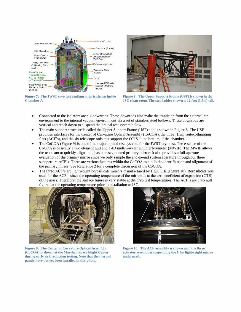
Figure 7: The JWST cryo test configuration is shown inside
Chamber A
Figure 8: The Upper Support Frame (USF) is shown in the
JSC clean room. The step ladder shown is 12 feet (3.7m) tall.
Connected to the isolators are six downrods. These downrods also make the transition from the external air
environment to the internal vacuum environment via a set of stainless steel bellows. These downrods are
vertical and reach down to suspend the optical test system below.
The main support structure is called the Upper Support Frame (USF) and is shown in Figure 8. The USF
provides interfaces for the Center of Curvature Optical Assembly (CoCOA), the three, 1.5m autocollimating
flats (ACF’s), and the six telescope rods that support the OTIS at the bottom of the chamber.
The CoCOA (Figure 9) is one of the major optical test systems for the JWST cryo test. The essence of the
CoCOA is basically a two element null and a 4D multiwavelength interferometer (MWIF). The MWIF allows
the test team to quickly align and phase the segmented primary mirror. It also provides a full aperture
evaluation of the primary mirror since we only sample the end-to-end system aperature through our three
subaperture ACF’s. There are various features within the CoCOA to aid in the identification and alignment of
the primary mirror. See Reference 2 for a complete discussion of the CoCOA.
The three ACF’s are lightweight borosilicate mirrors manufactured by HEXTEK (Figure 10). Borosilicate was
used for the ACF’s since the operating temperature of the mirrors is at the zero coeficient of expansion (CTE)
of the glass. Therefore, the surface figure is very stable at the cryo test temperatures. The ACF’s are cryo null
figured at the operating temperature prior to installation at JSC.
Figure 9: The Center of Curvature Optical Assembly
(CoCOA) is shown at the Marshall Space Flight Center
during early risk reduction testing. Note that the thermal
panels have not yet been installed in this photo.
Figure 10: The ACF assembly is shown with the three
actuator assemblies suspending the 1.5m lightweight mirror
underneath.

There are six telescope rods that hang from the USF
and support the Hardpoint/Offloader Supprt Structure
(HOSS). The very large stainless steel structure
(Figure 11) holds the flight OTIS in a kinematic
configuration of 2 monopod struts on one end and two
sets of bipods on the other end.
There are four photogrammetry (PG) systems
manufactured by Johns Hopkins University Instrument
Development Group that are attached to the walls of
the chamber (Figure 12). The camera systems in inside
pressure tight enclosures that are thermally controlled.
Each system rotates in a windmill fashion through 360
degrees of rotation. This PG system allows the test
team to understand where the hardware is in the
chamber to about 100 microns.
5. OGSE INTEGRATION
Over the period of 8 months, all this equipment was installed
into the JSC chamber and prepared for an initial Cryo
Commissioning Test.
During the time leading up to the final integration into the JSC
vacuum chamber, the CoCOA and the photogrammetry
canisters were tested at their operating temperatures. This risk
reduction provided high confidence that the equipment would
work, but this is the first time that the system was configured
and expected to work seamlessly as a system.
The major assembly that is installed near the top of the chamber
is the ACF/CoCOA/USF (ACU) assembly. This is a very large
optical assembly with the complexity on par with flight
hardware. To add to this complexity, the system is so large that even at ground level, the technicians were working 30
feet (9m) in the air. A specially designed and built piece of ground support equipment was needed for this task (Figure
13). This ACU Dolly as it is referred to be the assembly station and also allowed the entire subsystem to be rolled into
the chamber and lifted into position via a set of three hoists at the top of the chamber.
Figure 11: The Hardpoint/Offloader Support Structure (HOSS) is
shown after painting. The structure is approximately 30 feed (9m)
in length and width.
Figure 12: The four photogrammetry systems are
shown in their final “windmill” configuration in the
JSC vacuum chamber.
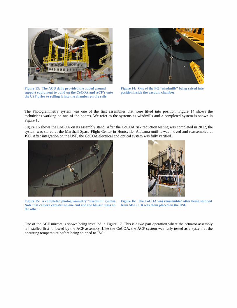
Figure 13: The ACU dolly provided the added ground
support equipment to build up the CoCOA and ACF’s onto
the USF prior to rolling it into the chamber on the rails.
Figure 14: One of the PG “windmills” being raised into
position inside the vacuum chamber.
The Photogrammetry system was one of the first assemblies that were lifted into position. Figure 14 shows the
technicians working on one of the booms. We refer to the systems as windmills and a completed system is shown in
Figure 15.
Figure 16 shows the CoCOA on its assembly stand. After the CoCOA risk reduction testing was completed in 2012, the
system was stored at the Marshall Space Flight Center in Huntsville, Alabama until it was moved and reassembled at
JSC. After integration on the USF, the CoCOA electrical and optical system was fully verified.
Figure 15: A completed photogrammetry “windmill” system.
Note that camera canister on one end and the ballast mass on
the other.
Figure 16: The CoCOA was reassembled after being shipped
from MSFC. It was them placed on the USF.
One of the ACF mirrors is shown being installed in Figure 17. This is a two part operation where the actuator assembly
is installed first followed by the ACF assembly. Like the CoCOA, the ACF system was fully tested as a system at the
operating temperature before being shipped to JSC.

Figure 17: The ACF actuator assembly (left) and the entire assembly (right) is shown in the pictures above.
Once the whole ACU assembly is completed, it is rolled into the chamber on the rail system (Figure 18) and the long
process of lifting the assembly into final position is started. As the system is lifted, the telescope rods are attached. The
telescope rods are 16 foot (4.9m) sections that also have thermal diodes and also photogrammetry targets so all the
cabling and other integration work was a serial effort. It was a long arduous process that took 3 days to raise and get into
final position (Figure 19).
Figure 18: The ACE assembly is ready to be rolled in and
lifted into position at the top of the chamber.
Figure 19: The ACU assembly being prepared to be raised into
position. This effort took three days to complete.
The final configuration with the 2X mass simulator is shown in Figure 20.
6. CHAMBER COMMISSIONING TEST
We are now ready to check out the system. In addition for an initial path to check out the systems operationally, we also
used this configuration as a load test for the hanging system. This test was the first time that the OGSE was taken cold
and an excellent risk reduction run prior to starting actual testing with the Pathfinder telescope.
In general, the system operated as expected. As with any highly complex system, we did come away with some lessons
learned from the experience. Several issues were identified during the Chamber Commissioning Test (CCT) as discussed
below:

We did have a significant leak in one area of the
CoCOA equipment. One of the sealing flanges that
allow the CoCOA equipment to stay at ambient pressure
was warped during manufacturing. So when the
chamber was evacuated, there was effectively a small
hole in chamber. A temporary fix was completed with
slowed the leak to an acceptable level and the test
proceeded.
One of the photogrammetry booms stopped working as
the system got colder. This was traced to some
contamination in one of the bearings. The aluminum
shards of contamination did not impact the warm
operation, but as the system cooled, the clearances in the
bearing got tighter. There became a point where the
motor could not overcome the contamination.
Other than these minor issues, the OGSE and chamber worked as
planned. At this point, the team completed the rework required to
repair the air leak in the CoCOA system and the cause of the PG
boom stalling was also repaired with new bearings with shields to
prevent any new contamination from entering the system.
Prior to OGSE#1, there is one additional piece of OGSE called
the Beam Image Analyzer (BIA). The BIA is actually an ISIM
simulator that allows the test team to understand the end-to-end
performance of the telescope. Even though the aft optics
assembly (AOS) was not be included in OGSE#1, the test team
wanted to have a dry run of the OGSE#2 operations to insure that
the BIA was functioning properly.
At this point, we are ready for the Pathfinder and some actual
optical testing!
7. OGSE#1 PREPARATION
The Pathfinder was delivered to JSC and the work to configure for OGSE#1 was started. The Pathfinder was moved
from the shipping container to the assembly cart as shown in Figure 21. The secondary mirror was then deployed (Figure
22) using the same support equipment that was used during mirror integration. That whole system was then moved over
to the HOSS and placed on the six hardpoint struts. This is actually the same configuration and the same struts that were
used at Goddard during the mirror integration.
Figure 20: The configuration for the CCT is complete.
The 2X OTIS mass simulator is shown and the rails
system is in the process of being removed in
preparation to close the door.
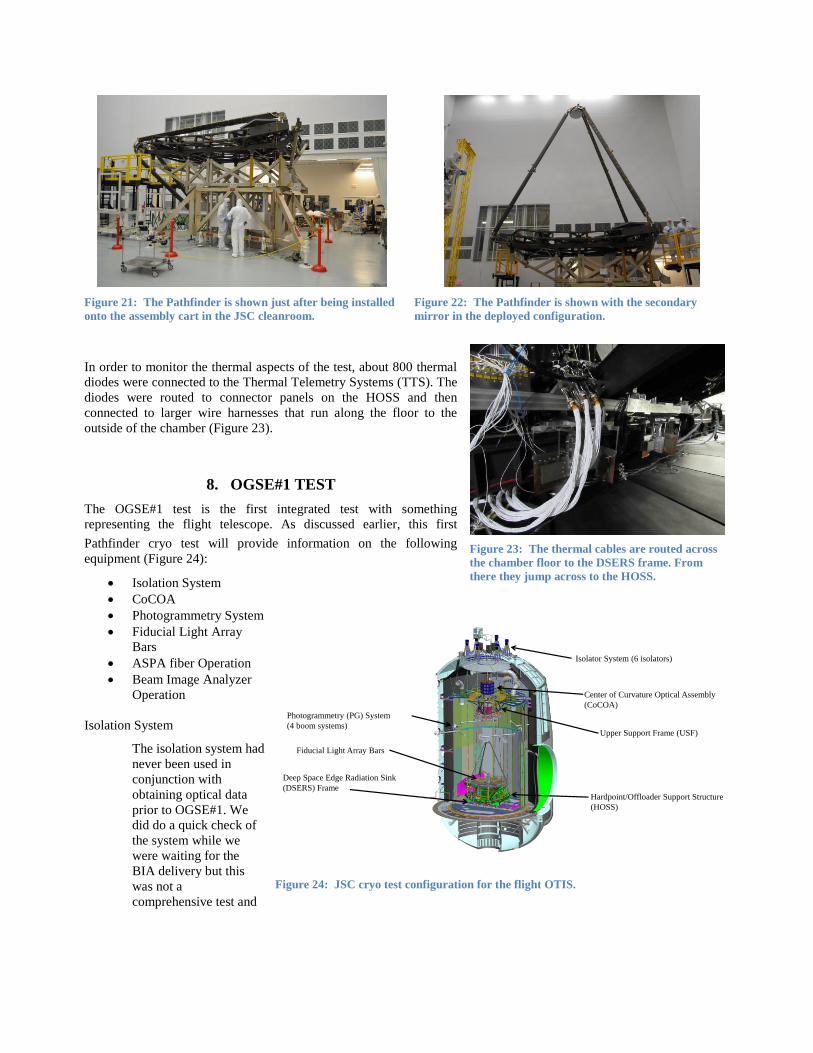
Figure 21: The Pathfinder is shown just after being installed
onto the assembly cart in the JSC cleanroom.
Figure 22: The Pathfinder is shown with the secondary
mirror in the deployed configuration.
In order to monitor the thermal aspects of the test, about 800 thermal
diodes were connected to the Thermal Telemetry Systems (TTS). The
diodes were routed to connector panels on the HOSS and then
connected to larger wire harnesses that run along the floor to the
outside of the chamber (Figure 23).
8. OGSE#1 TEST
The OGSE#1 test is the first integrated test with something
representing the flight telescope. As discussed earlier, this first
Pathfinder cryo test will provide information on the following
equipment (Figure 24):
Isolation System
CoCOA
Photogrammetry System
Fiducial Light Array
Bars
ASPA fiber Operation
Beam Image Analyzer
Operation
Isolation System
The isolation system had
never been used in
conjunction with
obtaining optical data
prior to OGSE#1. We
did do a quick check of
the system while we
were waiting for the
BIA delivery but this
was not a
comprehensive test and
Figure 23: The thermal cables are routed across
the chamber floor to the DSERS frame. From
there they jump across to the HOSS.
Isolator System (6 isolators)
Center of Curvature Optical Assembly
(CoCOA)
Upper Support Frame (USF)
Photogrammetry (PG) System
(4 boom systems)
Hardpoint/Offloader Support Structure
(HOSS)
Deep Space Edge Radiation Sink
(DSERS) Frame
Fiducial Light Array Bars
Figure 24: JSC cryo test configuration for the flight OTIS.

no optical data could be obtained during that test. The process involves adjusting the six isolators and
equalizing the load in each one that allows the system to “float” within the balance point of the isolators.
We were able to float the system very easily in air and readjust it quickly for vacuum operations. There is a
slight difference between air and vacuum since the system loses the air buoyancy and also due to the force on
the downrod feed through bellows. As the mirror segments were adjusted, the fringes were very stable which
indicated that the isolation system was working as designed. Figure 25 shows some dynamic data that shows a 6
order of magnitude decrease in response between 0.5Hz and 20Hz.
Figure 25: Mirror dynamic data from a high speed displacement measuring interferometer is shown above. Note that the
response is reduced by 6 orders of magnitude between 0.5Hz and 20Hz.
But as the system cooled, we did identify an issue that would remain a mystery until after the test was over. As
the temperature dropped and the long telescope rods got colder, the load on the isolators increased by about 680
kg (1500 pounds). In-situ testing indicated that the force acted like a large spring connected to ground. The cold
optical testing had to work through this added disturbance until we could correct the problem in subsequent
testing.
After the test was completed and the chamber door opened, the NASA/Harris team identified the issue as an
interference of the DSERS frame and the HOSS magnetic damper system. A large cap head screw protruded
from the DSERS frame where the mag damper system was located. This reduced clearance caused an
interference to occur where we basically lifted the corner of the DSERS frame that was tied to ground. The
resulting bending appeared to look like a large spring attached to the HOSS thus causing the increase in load as
the system cooled. This condition has been corrected for the OGSE#2 test which will start in September 2015.

The other condition that was identified was that the damping system first fundamental mode was designed to be
0.5 Hz. During the test, we identified that this first mode was 0.8 Hz. There are isolator parameters that can be
adjusted to move that first mode back down to 0.5 Hz and improve the overall performance of the system. This
was done late in the test and the Harris test team was able to demonstrate very stable fringes on the
interferometer.
CoCOA
The CoCOA had been though a cryo test in 2012 with WFE measured against a computer generated hologram
at the Marshall Space Flight Center as part of a risk reduction effort. But this is the first time that the CoCOA
would be operational in the JSC chamber while actually looking at flight primary mirror segment assemblies
(PMSA). There are various features in the CoCOA that allow the test team to quickly adjust and phase the
mirrors. Photogrammetry (PG) is used to set the position of the mirror relative to the Aft Optical Subsystem
(AOS) position before the CoCOA determines where to move the mirrors to create a phased monolithic PM.
There are several features that help with this process. There are two camera systems within the CoCOA that
allow the test team to fine tune the alignment of the PMSA’s. The Coarse Alignment Subsystem (CASS) is a
very large screen that is illuminated by the mirror returns (Figure 26). These images are so far out of alignment
that they would not get back through the hole in the null mirrors. The CASS images provide the knowledge to
be able to better align the PMSA’s to the interferometer. The next step is the alignment to the Fine Alignment
Subsystem (FASS). This is basically a camera looking at the hole going into the interferometer. Figure 27
shows the FASS images with respect to the interferometer reference hole. The returns are then easily driven
back into the interferometer where the final alignment can take place.
Figure 26: The CASS image on the left is just after the mirrors were deployed. As the mirrors are driven into alignment, the
images converge. The fid lights that are barely visible in the image provide references for the initial alignment.
Figure 27: The left FASS image is the “handoff” image after the CASS alignment is completed. The next task is to drive the
two PMSA images into the interferometer return hole as shown in the picture on the right.
Initial Deployment
CASS w/reference circle)
Preliminary Alignment
Scattered light from FASS alignment target hole (images aligned to target) (zoomed)
The cameras and MWIF are mounted to a bench on actuators that are used to align the pointing direction of the
COCOA optical axis using fiducial lights on the bars over the edge of the Pathfinder primary mirror location.
When all 18 mirrors are in place for OTIS, the returns could get very confusing. There is another feature that
was verified during OGSE#1 that isolated each of the PMSA’s to eliminate the confusion. By only illuminating
one mirror at a time, it is very easy to drive their alignment position. This worked flawlessly during the test.
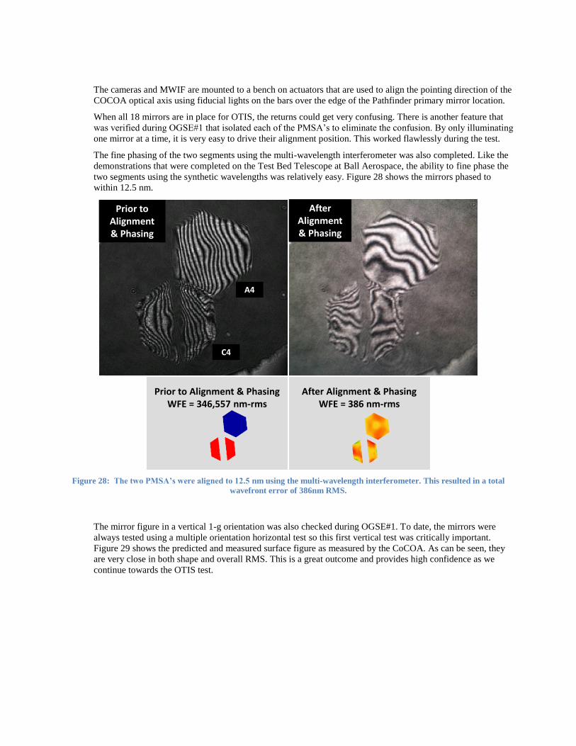
The fine phasing of the two segments using the multi-wavelength interferometer was also completed. Like the
demonstrations that were completed on the Test Bed Telescope at Ball Aerospace, the ability to fine phase the
two segments using the synthetic wavelengths was relatively easy. Figure 28 shows the mirrors phased to
within 12.5 nm.
Figure 28: The two PMSA’s were aligned to 12.5 nm using the multi-wavelength interferometer. This resulted in a total
wavefront error of 386nm RMS.
The mirror figure in a vertical 1-g orientation was also checked during OGSE#1. To date, the mirrors were
always tested using a multiple orientation horizontal test so this first vertical test was critically important.
Figure 29 shows the predicted and measured surface figure as measured by the CoCOA. As can be seen, they
are very close in both shape and overall RMS. This is a great outcome and provides high confidence as we
continue towards the OTIS test.
Prior to Alignment & PhasingWFE = 346,557 nm-rms
After Alignment & PhasingWFE = 386 nm-rms
A4
C4
Prior to Alignment& Phasing
After Alignment& Phasing

Figure 29: The comparison above shows the measured and predicted mirror wavefront error were very close. Note that the
distortion has not been removed from the test image on the left.
Then many measurements were collected to characterize range, resolution, repeatability, sensitivity to
adjustment, sensitivity to dynamic motion, and sensitivity to thermal distortion. In addition, processes were
demonstrated in the event of a CASS or FASS failure.
The final aspect of the CoCOA is a pair of Displacement Measuring Interferometers (DMI). The DMI also
provides high speed information at 7,000 measurements per second which could be evaluated in the time or
frequency domain (Figure 25). This capability provides excellent cryo dynamic data for analysis comparisons.
This device worked very well and provided some excellent dynamic feedback to the test team.
In general, the CoCOA worked as designed. There were some minor processing software upgrades that will be
completed prior to
OGSE#2, but these were
easily worked around for
this initial OGSE#1 test
program,
Photogrammetry (PG) System
The PG system worked as
designed during the test.
There were many
upgrades after the CCT
which allowed a near
flawless operational
system for OGSE#1.
The result of the PG
analysis show that the
system is working
extremely well. Figure 30
shows pictorially the
absolute accuracy in the
critical locations on the
hardware when compared
JSC Measured Cryo Figure:RMS WFE = 168 nm
Waves
-0.193
0.6521
0.2298
WAVEFRONT ABERRATION
Segment A4
Field = ( 0.000, 0.000) DegreesWavelength = 1000.0 nmDefocusing = 0.000000 mm
Predicted Gravity Cup Up (EDU has slight tilt) RMS WFE = 176 nm
Figure 30: The PG results are well within expectations. This data was verified using
laser radar as a cross check.
with a laser radar instrument at ambient temperature and pressure. Figure 31 shows the same data in tabular
form.
Average Absolute Error RMS (2σ ) 2σobject
V1 (mm) V2 (mm) V3 (mm) Mag. (mm) V1 (mm) V2 (mm) V3 (mm) V1 (mm) V2 (mm) V3 (mm) # points
AOS- Base 0.0334 -0.0457 -0.0170 0.0591 0.0489 0.0225 0.0356 0.0129 0.0390 0.1212 3
ARM -0.1136 -0.0809 -0.0364 0.1441 0.0420 0.0296 0.0376 0.0652 0.0513 0.1338 5
FLAB 0.0136 -0.0010 -0.0295 0.0325 0.0338 0.0858 0.0289 0.1201 0.0803 0.1560 13
PM-A4 0.0229 0.1584 0.0305 0.1629 0.0412 0.0273 0.0040 0.0943 0.0405 0.0626 2
PM-C4 0.0113 0.0521 0.0019 0.0533 0.0401 0.0268 0.0321 0.0327 0.0674 0.0908 5
SM 0.0362
0.1794
0.0308
4
Figure 31: The average absolute error is the result of comparing the laser radar and PG calculated locations. The RMS 2-
sigma error is the calculated standard deviation across four independent PG runs. The 2-sigma object error is the standard
deviation of the absolute errors of all the PG points that represent the object when laser radar and PG positions are
compared.
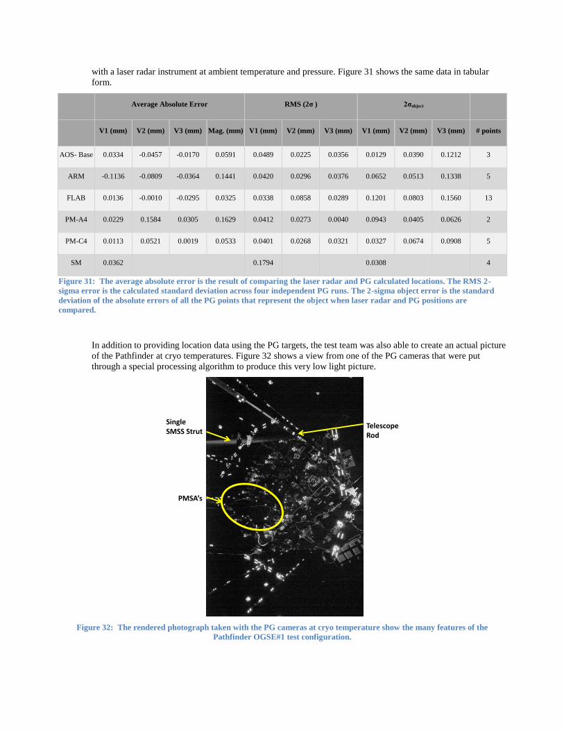
In addition to providing location data using the PG targets, the test team was also able to create an actual picture
of the Pathfinder at cryo temperatures. Figure 32 shows a view from one of the PG cameras that were put
through a special processing algorithm to produce this very low light picture.
Figure 32: The rendered photograph taken with the PG cameras at cryo temperature show the many features of the
Pathfinder OGSE#1 test configuration.
PMSA’s
Single SMSS Strut
TelescopeRod

Fiducial Light Array Bars
This was the first time that the fiducial light bars were in a cryo test. In addition to centering the COCOA
pointing direction, the light array will be used in the OGSE 2 and the OTIS tests to locate the relative alignment
of the pupil apertures. Each LED within the capture window of the BIA peering around the edge of the AOS
mass simulator peering towards the Secondary Mirror was checked for operating light with > 98% success!
There was some concern regarding the wavelength change of the LED’s as they got cold. Analysis and testing
indicated that the shift would be within range of the detectors. This initial test demonstrated the fid lights are
acceptable as the test program progresses.
ASPA Fiber Operation
In the CCT, we did observe some of the optical fibers were severely attenuating above 2 micrometer
wavelength. The OGSE 1 test proved a slight modification to the bend radius features eliminated that problem
for OGSE#2. This provides high confidence that the optical fibers that feed the source plate assembly will work
as designed.
Beam Image Analyzer Operation
For OGSE#1, the operation of the detectors and the various stages were verified for operation. This was
completed without issues. PG was used to verify the location of the detector head with respect to the Pathfinder
location. The LED’s on the Fid Bars were used as flat field and pupil imaging sources for the NIR detectors.
The COCOA heat with a thermal shutter was used as a source to check function of the InSb detector. This will
all be repeated for OGSE#2 when the Aft Optics Subsystem (AOS) is installed onto the Pathfinder. OGSE#1
verified that the various location could be viewed using the PG system.
9. SUMMARY
The early demonstrations and the Pathfinder Alignment, Integration, and Test program provided an excellent basis for
process development and early detection of test equipment problems. These first two cryo tests provide additional
confidence as the complexity of the next phases of the test program increase in OGSE#2 and Thermal Pathfinder. The
value of such a robust, high fidelity Pathfinder program cannot be understated as the ultimate in risk reduction.
REFERENCES
[1] Optomechanical integration and alignment verification of the James Webb Space Telescope (JWST)
optical telescope element
Conrad Wells, Matthew Coon, ITT Space Systems Division (United States)
Published in Proceedings Volume 7433: August 2009
[2] The center of curvature optical assembly for the JWST primary mirror cryogenic optical test: optical
verification
Conrad Wells, Gene Olczak, Cormic Merle, Tom Dey, Mark Waldman, Tony Whitman, Eric Wick, Aaron Peer,
ITT Corp. Geospatial Systems (United States)
Published in Proceedings Volume 7790: August 2010
[3] Architecting a revised optical test approach for JWST
Charlie Atkinson, Jonathan Arenberg, Northrop Grumman (United States); Gary Matthews, Mark Waldman, Alan
Wertheimer, Tony Whitman, ITT (United States); Jim Oschmann, Ball Aerospace& Technologies Corp. (United
States)
Published in Proceedings Volume 7010: August 2008
[4] The center of curvature optical assembly for the JWST primary mirror cryogenic optical test
Conrad Wells, Gene Olczak, Cormic Merle, Tom Dey, Mark Waldman, Tony Whitman, Eric Wick, Aaron Peer,
ITT Geospatial Systems (United States)
Published in Proceedings Volume 7739: July 2010

[5] JWST's cryogenic position metrology system
Tony L. Whitman, ITT Exelis Geospatial Systems (United States); Randolph P. Hammond, Joe Orndorff, Stephen
Hope, Stephen A. Smee, The Johns Hopkins Univ. (United States); Thomas Scorse, Keith A. Havey, Jr., ITT
Exelis Geospatial Systems (United States)
Published in Proceedings Volume 8442: August 2012
[6] The integration and test program of the James Webb Space Telescope
Randy A. Kimble, Pamela S. Davila, Charles E. Diaz, Lee D. Feinberg, Stuart D. Glazer, NASA Goddard Space
Flight Ctr. (United States); Gregory S. Jones, Northrop Grumman Aerospace Systems (United States); James M.
Marsh, NASA Goddard Space Flight Ctr (United States); Gary W. Matthews, ITT Exelis Geospatial Systems
(United States); Douglas B. McGuffey, NASA Goddard Space Flight Ctr. (United States); Patrick H. O'Rear,
NASA Johnson Space Flight Ctr. (United States); Deborah D. Ramey, NASA Goddard Space Flight Ctr. (United
States); Carl A. Reis, NASA Johnson Space Flight Ctr. (United States); Scott C. Texter, Northrop Grumman
Aerospace Systems (United States); Tony L. Whitman, ITT Exelis Geospatial Systems (United States)
Published in Proceedings Volume 8442: August 2012
[7] Assembly integration and ambient testing of the James Webb Space Telescope primary mirror
Conrad Wells, Tony Whitman, John Hannon, Art Jensen, Eastman Kodak Co. (United States)
Published in Proceedings Volume 5487: October 2004
[8] Integration and verification of the James Webb Space Telescope
Charles B. Atkinson, Pat Harrison, Northrop Grumman Corp. (United States); Gary Matthews, Eastman Kodak
Co. (United States); Paul Atcheson, Ball Aerospace& Technologies Corp. (United States)
Published in Proceedings Volume 5180: December 2003
[9] James Webb Space Telescope system cryogenic optical test plans
Lee D. Feinberg, NASA Goddard Space Flight Ctr. (United States); Allison Barto, Ball Aerospace& Technologies
Corp. (United States); Mark Waldman, Sigma Space Corp. (United States); Tony Whitman, ITT Corp. Geospatial
Systems (United States)
Published in Proceedings Volume 8150: September 2011
[10] James Webb Space Telescope primary mirror integration: testing the multiwavelength interferometer on
the test bed telescope
Gene Olczak, David J. Fischer, Mark Connelly, Conrad Wells, ITT Corp. Geospatial Systems (United States)
Published in Proceedings Volume 8146: September 2011
[11] James Webb Space Telescope (JWST) Optical Telescope Element (OTE) Pathfinder status and plans
Lee D. Feinberg, Ritva A. Keski-Kuha, NASA Goddard Space Flight Ctr. (United States); Charles B. Atkinson,
Northrop Grumman Aerospace Systems (United States); Andrew J. Booth, Sigma Space Corp. (United States);
Tony L. Whitman, Exelis Geospatial Systems (United States)
Published in Proceedings Volume 9143: Space Telescopes and Instrumentation 2014: Optical, Infrared, and
Millimeter Wave: September 2014
[12] JWST telescope integration and test status
Gary W. Matthews, Thomas R. Scorse, Scott Kennard, John Spina, Tony Whitman, Exelis Inc. (United States);
Scott Texter, Charles Atkinson, Greg Young, Northrop Grumman Aerospace Systems (United States); Ritva A.
Keski-Kuha, James M. Marsh, Juli Lander, Lee D. Feinberg, NASA Goddard Space Flight Ctr. (United States)
Published in Proceedings Volume 9143: Space Telescopes and Instrumentation 2014: Optical, Infrared, and
Millimeter Wave: September 2014
[13] Use of a pathfinder optical telescope element for James Webb Space Telescope risk mitigation

Lee D. Feinberg, Ritva Keski-Kuha, NASA Goddard Space Flight Ctr. (United States); Charlie Atkinson, Scott C.
Texter, Northrop Grumman Aerospace Systems (United States)
Published in Proceedings Volume 7731: Space Telescopes and Instrumentation 2010: Optical, Infrared, and
Millimeter Wave: July 2010