june09 - slot techslot-tech.com/members/magazine/lores/june09.pdfpage 6 slot tech magazine june 2009...
TRANSCRIPT


June 2009Slot Tech MagazinePage 4
Randy Fromm's
Slot Tech Magazine
EditorRandy Fromm
Technical WritersTed Befus, Kevin Noble,
Herschel Peeler, PatPorath, James Borg
Slot Tech Magazine is publishedmonthly bySlot Tech Magazine1944 Falmouth Dr.El Cajon, CA 92020-2827tel.619.593.6131 fax.619.593.6132e-mail [email protected] the website at slot-techs.com
SUBSCRIPTIONSDomestic (North America)1 year - $60.002 years - $120.00International1 year - $120.002 years - $240.00
Subscribe online atslot-techs.com
Copyright 2009 under the UniversalCopyright Convention. All rights re-served.
Slot Tech Maga-zine
June 2009
Inside Slot Tech Magazine
Page 4 - EditorialPage 6 - Problem: Cocktail Waitresses With Skirts TooShort and Necklines Too LowPage 8 - Ceronix CCFL ReplacementPage 12 - Slot Tech Training at Twin Pine CasinoPage 13 - Save $$$ Through CCFL Backlight DimmingPage 17 - TechFest 19 - Mystic Lake CasinoPage 18 - Quick and Simple Repairs #51Page 20 - Kingbright Releases New Optoelectronics Catalog 2009-2010Page 21 - The Chicken or the Egg?Page 26 - Subscriptions and Order Form
Slot Tech Magazine is anofficial publication of
Randy Fromm
Randy Fromm - Publisher
Printed back issues are available for only one year from the date ofpublication. All single issues of Slot Tech Magazine are $10.00/ea.
For further details on the contents of each issue, please refer to thewebsite at slot-techs.com. To order, fax a PO or e-mail a note listingthe issues you need.
Complete archive (2001 to present) available online. Visitslot-techs.com for details.
Dear Friends of Slot Tech Magazine,
I received a short contribution from our old friend Herschel Peeler thismonth. He submitted it with a humorous title. As a writer myself, I havealways hated it when an editor changed the title of one of my stories so histitle “Problem: Cocktail Waitresses With Skirts Too Short and NecklinesToo Low” stands. Yes, I DO realize we have many female slot techs but hereat Slot Tech Magazine, we try to make technical articles just a wee bit moreinteresting and funny and I would ask that you accept a little light humorin the spirit it was intended. I’ll try to include something that might bemildly offensive to cat lovers, the disabled or a religious group in a futureissue.
Moving on . . . This issue contains some very important information. Theknowledge in this issue will save your casino thousands of dollars a year,starting the instant you read the article on page 13, put down the maga-zine, open a slot machine with an LCD monitor and make a simple adjust-ment. Do this 1000 times and you will save your casino over six grand!
We also have an excellent contribution from our friends at Ceronix on thetopic of CCFL replacement. In older LCD monitors, this was sort of a painin the brain as you sometimes had to disassemble all the films to get to thelamps. Now, it’s a bit more straightforward. This article shows you how.Replacement lamps are available from CI Innovations or Ceronix, bothsupporters of Slot Tech Magazine. Thanks.
We also have some coverage of a couple of slot tech training events as wellas two excellent contributions from Malta’s James Borg and homeboy PatPorath.
That’s all for this month. See you at the casino.

Slot Tech MagazineJune 2009 Page 5

June 2009Slot Tech MagazinePage 6
Slot Tech Feature Article
Yes, I know that hasnothing to do with theproblem but I figured
that headline would get yourattention quicker than “NoComm on an Acres Account-ing System” or “Spilled DrinkKills the Casino.” So here’sthe real problem, two banksof games on the sides of abar shows no communicationwith the Acres system, nowelcome message. One sideis location 030101 to 030114,the other side is location030201 to 030212. Both areon one channel of the samebank controller. Five min-utes before it was my time togo home, they both decidedto die at once.
The Acres event monitorshows that this bank is dead.All I show is a white dot thatshould be green. Only thatone string seems to be bad.At the bank controller, LEDsegment “G” is out, indicat-ing no communication online OL1. So far this agreeswith our symptom. Afterconsidering our options, withthe new casino managerlooking over our shoulder,the tech and I decide to tryswitching to our backupcable. Most of our banks havetwo CAT5 cables running
from the patch panel in thecomputer room to the floorbanks. We swap cables atboth ends. Still down. Trying to make a good im-pression on our new man-ager, we next try powercycling the Bank Controller.The “G” segment comes onfor a minute then dies againas the Bank Controller triesto communicate with thebanks but stops trying after awhile. “G” stays out. It isn’t acertain conclusion but thebest guess is that it isn’t theBank Controller. The techand I throw techno-babbleback and forth for a fewminutes, the manager lookslost (that was the intention).We decide that it must beone game dragging down thewhole string. “Can thatreally happen,” asks themanager. “Can one gamebeing down take out all ofthe games?” “Sure,” I say.“All the games are hooked inparallel. If one shorts out itcan take down all of thegames on that line.” The tech and I break thestring about half waythrough at game 030114, oneend half way around the bar.Half the games come up,030101 to 030114. Our badgame is somewhere on030201 to 030112. The gameis afoot. Thankfully themanager gets called awayand the tech and I can getdown to business again.Continuing our half-at-timeline breaking we get theproblem down to the game at030204. When that game isremoved from the line allother games come up. Themanager comes back throughlooking for a progress check.The tech hands him theboard covered with goo from
a spilled drink, maybe two orthree days ago. “Spilleddrink,” says the tech. “That took out all thegames?” The manager looksat all the other games upand running and seemssatisfied. “Do we have an-other board?” “Not inhouse, of course. But we canget one quick,” he says. The next day our new boardarrives from IGT. We plug itin, clear it and configure itwith the new location andasset number. Still down.Luckily the new managerwasn’t around. The tech andI take a good look at the newboard. EPROM version AE-02,versus AE-01 on the oldboard. An EPROM swap andthe board and the gamecomes up. With the Wel-come Message on all thedisplays, the “G” segmentblinking as it should, greendots on the Event Monitor,all is right with the worldand I finally get to go home,just a little bit late. Log outon the system, turn off thelight, say good night, Gracie.
- Herschel Peeler [email protected]
Problem: Cocktail Waitresses With Skirts TooShort and Necklines Too Low
By Herschel Peeler

Slot Tech MagazineJune 2009 Page 7

June 2009Slot Tech MagazinePage 8
Slot Tech Feature Article
CCFLs-Cold CathodeFlorescent Lamps-AKA Cold Cathode
Florescent Tubes (CCFT). Ifyou notice your LCD panelflickering or turning onthen shutting off or even nopicture at all, you will, mostlikely, have to replace thetubes. The cost of the tubesis a fraction of the cost toreplace the complete LCDpanel and an even smallerfraction of the cost of anentire replacement moni-tor.
Please read this articlecompletely before startingthis project. When workingon LCD panels, make surethe work surface is cleanand free of contaminants. Apiece of cloth or foam isrecommended. The paneldescribed in this article is aSamsung 19” TFTLTM190E4 Ceronix PN-CPP1701. The Samsung 17”TFT LTM170E8-L01-L Cero-nix PN-CPP1700 panel willfollow the same procedureas the 19” panel. TheSamsung 15” TFTLTM150X0-L01 is toosimple to address here indetail. Simply remove thetwo screws holding the tubeassembly, then slide theassembly out .
The first step is to removethe LCD panel from theframe/ electronics. Remove
Figure 1
Figure 2
Figure 3
Ceronix CCFL Replacement

Slot Tech MagazineJune 2009 Page 9
June 2009Slot Tech MagazinePage 10
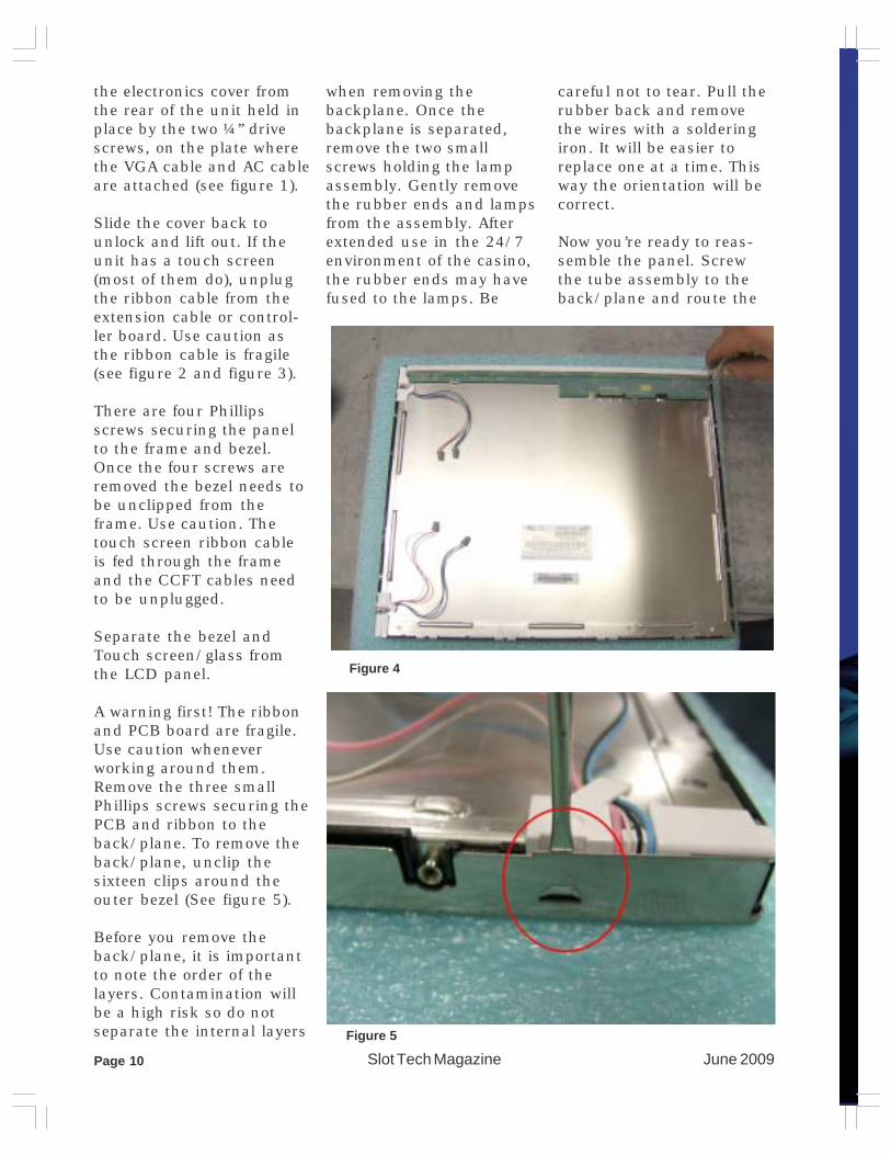
the electronics cover fromthe rear of the unit held inplace by the two ¼” drivescrews, on the plate wherethe VGA cable and AC cableare attached (see figure 1).
Slide the cover back tounlock and lift out. If theunit has a touch screen(most of them do), unplugthe ribbon cable from theextension cable or control-ler board. Use caution asthe ribbon cable is fragile(see figure 2 and figure 3).
There are four Phillipsscrews securing the panelto the frame and bezel.Once the four screws areremoved the bezel needs tobe unclipped from theframe. Use caution. Thetouch screen ribbon cableis fed through the frameand the CCFT cables needto be unplugged.
Separate the bezel andTouch screen/glass fromthe LCD panel.
A warning first! The ribbonand PCB board are fragile.Use caution wheneverworking around them.Remove the three smallPhillips screws securing thePCB and ribbon to theback/plane. To remove theback/plane, unclip thesixteen clips around theouter bezel (See figure 5).
Before you remove theback/plane, it is importantto note the order of thelayers. Contamination willbe a high risk so do notseparate the internal layers
when removing thebackplane. Once thebackplane is separated,remove the two smallscrews holding the lampassembly. Gently removethe rubber ends and lampsfrom the assembly. Afterextended use in the 24/7environment of the casino,the rubber ends may havefused to the lamps. Be
careful not to tear. Pull therubber back and removethe wires with a solderingiron. It will be easier toreplace one at a time. Thisway the orientation will becorrect.
Now you’re ready to reas-semble the panel. Screwthe tube assembly to theback/plane and route the
Figure 4
Figure 5

Slot Tech MagazineJune 2009 Page 11

June 2009Slot Tech MagazinePage 12
wires in their holder. Snapthe back/plane back intothe panel. If you encounterany resistance, do notforce. Simply tap the oppo-site side on edge and thelayers will line right up.
When all the clips aresnapped in, screw the PCBto the panel and reas-semble.
The two most commonproblems seen after chang-ing the tubes are solid colorlines running top to bottomand inverter flashing onthen off. If the lines arepresent, the ribbon to thePCB was nicked. If flashingon then off, the rubber orwire shielding is broken onthe tube wires.
For more information, con-tact Ceronix distributorSuzo-Happ or your localCeronix distributor. For a
list of distributors, pleasevisit the website atceronix.com or contactCeronix at 530-886-6400.
Figure 6. Here you see the CCFL tubes removed from the channel(top) and a close-up of the worn tube ends with the rubber bootpulled back to expose the solder points.
Slot Tech Event - Slot Tech Training at Twin Pine Casino
Some of Indian Country is so darned beautiful, it makes goingto work each day a real pleasure, even if it means workinginside a double-wide trailer, parked outside the brand new
Twin Pine Casino in Middletown, California. This is in LakeCounty. You’ve probably never heard of Lake County but I’ll wagerthat you’ve heard of neighboring Napa and Sonoma counties. Thisis the heart of California’s wine country and it’s a beautiful placeto visit in the spring which is when Slot Tech Magazine’s team oftechnical instructors spent two weeks working with a baker’s dozenof the casino’s slot techs. I (Randy Fromm) did the bulk of thetraining, including power supplies, CRT monitors and LCD monitorrepair. We were lucky to have a Konami machine’s LCD monitor failwhile we were having ourhands-on repair lab. Wesnagged the monitor out of themachine, replaced a single(obviously bad) electrolyticcapacitor on the inverter PCBand had the monitor back in themachine in about 20 minutes.That’s what I’m talkin’ about!Component-level electronicrepair can be pretty easy andthis was a good example. Alsoincluded in the class was a dayof Futurelogic Ticket Printerrepair (presented by DavidOldham of Suzo-Happ) and a dayof JCM bill validator repair,presented by Jack Geller.
Attending the class from Twin Pine Casino were GwenBrown, Serena Velarde, Darrell Yee, Trung Nguyen,Felipe Leon, Jan Albertson, Dan Buck, David Stevens,Shawn Arson, Manuel Ledesma, Richard Russo, TonyJackson & Katie Marks.
Trung Nguyen and GwenBrown work on a CRT monitorduring the hands-on repairlab.

Slot Tech MagazineJune 2009 Page 13
Slot Tech Feature Article
Sencore’s DonMulterer gave a pre-sentation at TechFest
19. He was his usual, high-energy self, with a splendidpresentation on LCD moni-tor operation. If you everwanted to learn way morethan you need to knowabout LCD operation, Doncrammed it into a two-hour,pedal-to-the-metal presen-tation. But for me, the bestpart of the presentationwasn’t the theory of opera-tion. It wasn’t the A to Dconversion. It wasn’t theRoyer oscillator. It was asimple demonstration of an
experiment that I was actu-ally all set up to performbut I was looking for some-thing else and I totallymissed it. It is importantand will have an immediateimpact on your casino’senergy consumption.
The demonstration was adiscussion of using Pulse-Width Modulation (PWM) tocontrol the brightness ofthe backlight CCFLs inLCD monitors. We wereusing an oscilloscope tolook at the 2kV sine wavethat drives the lamps. Donalso had a small digital
ammeter/wattmeter (called“Watt’s Up”) in series withthe +12 VDC power supply.We were drawing around4.6 amps for a total powerconsumption of 55 Watts.
Using the OSD menu, Donreduced the brightnessfrom 100% and as he did,we watched the waveformon the oscilloscope’s dis-
Save $$$ Through CCFLBacklight Dimming
June 2009Slot Tech MagazinePage 14
play become chopped up ata rate of 300 Hz. Littlepieces of the sine wavebegan to disappear. Whenwe were at around 75%duty cycle, the display stilllooked plenty bright butthe meter showed a reduc-tion from 4.6 to 3.4 Amps.That’s around 25% lesscurrent, which makessense since we were ataround 75% duty cycle.
I haven’t tested every moni-tor in use today but thenumbers seem fairly con-sistent across the board forthe units I have tested. Youcan reduce the brightnessand easily obtain a 20%-25% reduction in powerconsumption. I cannot saywhat this might do to thelife expectancy of the lampsthemselves. Logic dictatesthat they should last longerbut I have no empiricalevidence to back up thatassumption.
The issue of “attractiveness”comes into play. It’s easy toargue that brighter is betterbut that’s a subjectiveevaluation so I cannotspeak to that other than tosay that it looks perfectlyfine to me to run at thisslightly reduced brightness.Heck, maybe it’s easier onthe eyes and the customersmight like it better!
I would only state the obvi-ous and that is that all ofthe monitors in a bank ofidentical machines (videopoker or Game King forexample) should be ad-justed to precisely the same
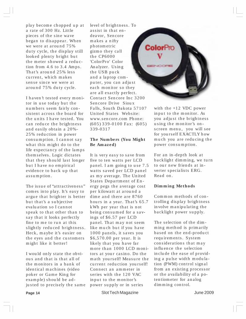
level of brightness. Toassist in that en-deavor, Sencoremakes a niftyphotometricgizmo they callthe CP6000'ColorPro' ColorAnalyzer. Usingthe USB puckand a laptop com-puter, you can adjusteach monitor so theyare all exactly perfect.Contact Sencore Inc 3200Sencore Drive SiouxFalls, South Dakota 57107United States Website: www.sencore.com Phone: (605) 339-0100 Fax: (605)339-0317
The Numbers (You MightBe Amazed)
It is very easy to save fromfive to ten watts per LCDpanel. I am going to use 7.5watts saved per LCD panelas my average. The UnitedStates Department of En-ergy pegs the average costper kilowatt at around adime and there are 8760hours in a year. That’s 65.7kWh per year that is notbeing consumed for a sav-ings of $6.57 per LCDpanel. That may not seemlike much but if you have1000 panels, it saves you$6,570.00 per year. It islikely that you have farmore than 1000 LCD moni-tors at your casino. Do themath yourself! Measure thecurrent reduction yourself!Connect an ammeter inseries with the 120 VACinput to the monitor’spower supply or in series
with the +12 VDC powerinput to the monitor. Asyou adjust the brightnessusing the monitor’s on-screen menu, you will seefor yourself EXACTLY howmuch you are reducing thepower consumption.
For an in-depth look atbacklight dimming, we turnto our new friends at in-verter specialists ERG.Read on.
Dimming Methods
Common methods of con-trolling display brightnessinvolve manipulating thebacklight power supply.
The selection of the dim-ming method is primarilybased on the end-productrequirements. Systemconsiderations that mayinfluence the selectioninclude the ease of provid-ing a pulse width modula-tion (PWM) control signalfrom an existing processoror the availability of a po-tentiometer for analogdimming control.

Slot Tech MagazineJune 2009 Page 15
There are two basic meth-ods for controlling thebrightness of a cold-cath-ode fluorescent lamp. Onemethod controls the drivecurrent amplitude (analogdimming), and the othercontrols the duration oftube operation (PWM orburst mode). It is also pos-sible to combine the twomethods.
Analog dimming involvescontrolling the tube'sbrightness in response to areduction in the amplitudeof the drive current (seeFig. 1). Probably the sim-plest form of dimming, itrequires a simple potenti-ometer as the controllingelement and is applicableto the most basic invertersby merely controlling theinput voltage to the in-verter. Many inverters in-clude a provision for accept-ing an analog voltage inputat a low current level tocontrol the amplitude of theoutput.
Although analog dimmingis the simplest, it is also the
most limitedmethod interms ofdimmablerange. As thecurrent tothe tube isdecreased,the tubereaches apoint whereit no longerprovidesuniformconsistentlight because the tempera-ture of the electrodes isreduced to a point whereflickering or a "worming"pattern begins to occur inthe tube. Analog dimmingis generally adequate fordimming to no less than30% of fullbrightnessin new con-dition. Inaddition, it isgenerally notpossible tostart thelamp in adimmedstate whenusing the
analog method. It is best tostart the lamp at full bright-ness and then dim down tothe desired level. In PWMdimming (see Fig. 2), thefluorescent tube is actuallyturned on and off at a fre-quency that is higher than
Fig. 1. In analog dimming, the tube isdimmed in response to a reduction in theamplitude of the drive current.
Fig. 2. In dimming by pulse width modula-tion, the fluorescent tube is actuallyturned on and off at a frequency that ishigher than the human eye can see.

June 2009Slot Tech MagazinePage 16
the human eye can see.The level of perceivedbrightness then dependson the proportion of timethat the tube is lit. If thetube is on for 50% of thetime, the eye will perceive aconstant level of brightnessthat is 50% of the on-periodbrightness.
A wide range of dimming ispossible using the PWMmethod. For most applica-tions, dimming to 200:1 or0.5% is readily achievable.In many cases, dependingon the backlight assembly,ratios of greater than1,000:1 can be achieved.
A number of special consid-erations are relevant toPWM dimming. First, thefrequency of the on-offcycle must be high enoughso that the human eyeperceives a continuouslighting--above 50 Hz gen-erally satisfies this require-ment.
In addition, the cycling of
the lamp must not interferewith the refresh cycle of thedisplay. A frequency mul-tiple of 2.5 times the re-fresh frequency is generallyfound to be very effective ineliminating interference. Ifthis is not possible, it maybe necessary to synchro-nize the PWM with thevertical refresh cycle toprevent interference.
Finally, noise--both electri-cal and acoustic--may be aconsideration with PWMdimming. While a con-stantly running inverterproducing a sine wavecurrent to the tube is rea-sonably quiet, turning it onand off in the PWM modecan create electromagneticinterference.
In addition, the inverteroscillating at 30 to 60 kHzproduces no acoustic noisesince it is above the audiblerange. Introducing PWM at250 Hz is well within theaudible range and canproduce acoustic noise.
It's In the Backlight
These considerations arefactors in the choice of aninverter to power the fluo-rescent tube. It should beunderstood, however, thatthe ability to dim the dis-play to low levels withoutflicker is ultimately con-trolled by the characteris-tics of the fluorescent tuberather than the inverter. Afluorescent tube's bright-ness, even with preciselycontrolled drive current,starts to decrease from themoment it is first switchedon and continues to de-crease throughout its use-ful life.
In addition, the brightnesschanges drastically withtemperature, decreasing byas much as 75% with dropsin temperature from 25° to0°C. However, if the tem-perature rises from 25° to40°C--not unusual within aslot machine--the bright-ness may likely increase by30%. - STM
Fifty slot techs attended TechFest 19, held at Mystic Lake Casino

Slot Tech MagazineJune 2009 Page 17
Slot Tech Event
Repair Monitors, Power Supplies, Gameboards?Repair Monitors, Power Supplies, Gameboards?
Check any Electrolytic Capacitor In-Circuit with100% Accuracy in 3 Seconds---GUARANTEED*
Automatically discharges capacitor
Checks DCR with alerts for shorts
Measures DCR to 500 ohms
Measures ESR from 0.1 to 20 ohms
Checks caps from .47uF to 2200uF
Beeps one to five beeps for quality
Three-color chart for good-fair-bad
*range 0.47uF - 2.2KuF 90-day money-back guarantee
Portable, Easy to Use, Inexpensive, Highly Recommended by
leaders in the industry. CapAnalyzer 88A by EDS, Inc.
At your favorite distributor, or call 561-487-6103 or www.eds-inc.com
TechFest 19 - Mystic Lake Casino
TechFest 19 was held at Mystic Lake Casino May12-14 2009. This was the sixth time that the
three-day event has been heldat Mystic Lake. Presentations were
made on power supply repair,CRT monitor repair, LCD moni-
tor repair, touchscreens,printers and bill validators.Clockwise from the right arepresenters David Oldham(Suzo-Happ), Paul Hatin andMark Roberts (3M TouchSystems), Troy Nofziger(Ceronix), Don Multerer(Sencore) Russ Wigé (Trans-act Technologies) and JackGeller from JCM.
If you are interested insponsoring TechFest at yourproperty, please contact SlotTech Magazine for details.
- STM
June 2009Slot Tech MagazinePage 18
Slot Tech Feature Article
WBA Stacker Box Problem
While a co-workerwas checking outand repairing
some WBA stacker boxes(a.k.a. cash boxes, cashcans) the individual actu-ally found a paper clipjammed near the pusherassembly. It had jammedand didn't allow the pusherplate to move downward.The box was marked "BVkeeps cycling." I guess thiswould have to go into thecasino "Unsolved Mysteries"files. I've run into a fewticket printers on thebench that when examinedclosely, were found to havehad a small piece of paperjammed near a roller.Hmmm, could that be theproblem? It's kind of nicewhen problems are obviousonce in a while.
Bally EVO Wouldn't Boot
I took a look at a Bally EVOgame (this one has an LCD
up top plus the regularreels) and it didn't want toboot up all the way. On the"Brain Box" (located justbelow the reels) there is aCD drive. On it, there isusually a light that indi-cates if the CD is beingread. If so, the light willflash rapidly. This particu-lar drive didn't have thelight on it so I couldn't tellif it was reading or not. Onthe LCD (during the bootprocess) it seemed that the"checking CD" icon wasn'tloading properly. Also thegame wouldn't boot up allthe way. I grabbed a spareBrain Box that was marked"should be good" and madesure it had the light on thedrive. Once it was installedin the game, it appearedthat the CD was readingbut the game still wouldn'tboot up. I reseated themain processor whichdidn't help either. The CDitself was checked to see ifit was clean. I have run intoa few games in the pastthat the only problem was adirty or badly scratchedCD. This one looked OK.Subsequently, a knowngood replacement BrainBox was installed and thegame fully booted up.
Editor’s Note: IMHO, this isa bad practice. Returninguntested parts and sub-assemblies to stock (at leastthis one had a tag, eventhough it was actually bad,it implied that it was un-tested) is just asking fortrouble. Look at how muchtime was wasted here.
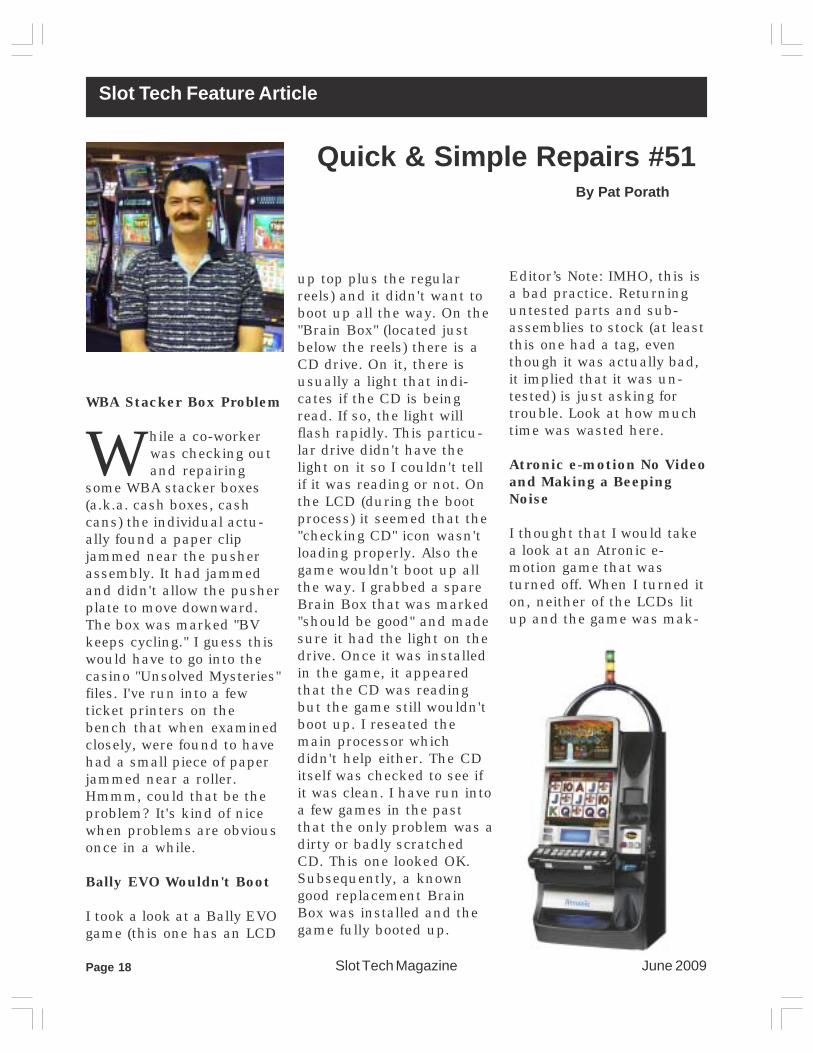
Atronic e-motion No Videoand Making a BeepingNoise
I thought that I would takea look at an Atronic e-motion game that wasturned off. When I turned iton, neither of the LCDs litup and the game was mak-
Quick & Simple Repairs #51By Pat Porath
Slot Tech MagazineJune 2009 Page 19
ing a beeping noise. I hadnever heard this kind ofbeep from an e-motiongame before. What did thismean? Where should I evenstart? It appeared thatthere was a power problembecause the LCDs wereblack. To start off, I re-placed the video card butthat didn't help. Next, thepower supply was replaced.It still didn't have anypower or graphics to theLCDs and it was still beep-ing. Maybe the main pro-cessor board had an issue?I swapped it with a similargame with still no changein the problem. I thoughtabout changing themotherboard but being thatI was the only tech on duty,I’d best not tear too muchinto it. The following day Icame in and the game wasup and running. Awesome!I read our log book and sawthat the motherboard had
been replaced and that wasthe problem. So, if you havean e-motion game thatdoesn't have any video andis making a beeping noise,the problem just may be abad motherboard.
Aristocrat MKIV PowerProblem
I came upon an older Aris-tocrat that had a powerproblem. The main powerswitch was turned on andthe Oasis display hadpower but the game didn'thave any power. This isusually an indication of abad power supply. Once ina while, if you let the gamecool down and turn thepower switch back on, thegame will come back up.Also, once in a while whenyou unplug the main powercord for a minute or so, thepower will come back. If itdoes, more than likely it
will need to be replacedlater on. They are quitesimple to replace. One ofthe hardest parts (on anupright game) is removingthe bill acceptor assembly.The trick is, there are twosmall screws under thecashbox door. With thescrews removed and thesmall metal plate taken off,the assembly is pretty easyto remove. Of course thereare the bill accepter con-nectors and the powersupply connectors but itlooks worse than what itactually is. With this par-ticular game, I replaced thepower supply and turnedon the power switch. Bingo!The game was back online.
Aristocrat SPC BoardLosing Power
Have you ever had an SPCboard lose power? Youreboot it and a while later it

June 2009Slot Tech MagazinePage 20
loses power again. It tookme a while to figure it out. Ikept getting called to thisgame and the power LEDon the SPC board was goingout. I would reboot it andabout an hour later or so, itwould lose power again. Ichecked all of the connec-tions, even the connectionson the motherboard. Theywere all snug and in place.I also tried a few RAMclears on the SPC boardbut that didn't help either.Maybe it was a bad SPCboard? I replaced it and theboard wasn't the problemeither. On the main proces-sor there is a small boardthat looks similar to amemory stick for a com-puter. It was swapped and Ihaven't heard a problemfrom the game since. So, ifthere are power problemsor sometimes other prob-lems with the SPC board,try swapping the smallboard on the main proces-sor.
Konami Progressive Witha Communication ErrorThat Wouldn't Clear
I received a call for an up-right video Konami gamethat had a communicationserror that didn't want toclear. I wasn't sure if it wason the Oasis end or thegame end at first. The Sen-tinel was rebooted alongwith the game. Next, Ireseated the main proces-sor board and communica-tion board up top but nei-ther one helped. It still hadthe error. Maybe the gameoptions had been lost? I
checked them and theywere OK too. One thingthat was kind of unusual isI still had my main door"OPEN" and "CLOSED" onthe Oasis display. Thismeant that I did in facthave communication FROMthe game TO the Sentinal.Also on the Oasis display Ihad my Sentinal ID num-ber and the DPU numberwhich meant that I hadcommunication FROM theSentinal TO the Oasis sys-tem. What was going on?So far everything is check-ing out OK. Next, I checkedin the lower part of thegame and bumped a wireon the small progressive
board (also known as aSMIB) and the lights flick-ered on it. This was veryinteresting. I wiggled thewires again and the powerto the board came on; itwas simply a loose connec-tion. Now that the boardhad power, I closed thedoor on the game and theerror cleared. Since theboard was located in theback lower part of the gameI didn't notice it until I hadlooked further into theproblem. This was simplebut not so quick!
- Pat [email protected]
Kingbright Releases New Optoelectronics Catalog 2009-2010
Kingbright Corporation, a TS 16949, ISO 9001, ISO 14001 certified LEDmanufacturer, has released its 2009-2010 optoelectronics catalogfeaturing a complete line of ultra-high efficiency LEDs with optimizedperformance. The full-color literature contains detailed specifications,diagrams, and process recommendations for Kingbright’s diverse range ofLED products including low profile SMD Displays, Multi-Color LED Lampsand High Brightness SMD LEDs. This comprehensive solution guide isspecially designed to achieve ultimate LED design requirements. AneCatalog version and 3D specifications are available onwww.KingbrightUSA.com with quick downloading feature. Kingbrightoffers full custom LED options in packages with any desired shape, form,and color to enhance engineers’ design solutions.

Slot Tech MagazineJune 2009 Page 21
Slot Tech Feature Article
Have you ever found yourself in a situation whereyou’ve happened to notice
a fault on a piece of equipment, amonitor for instance, and some-how you weren’t sort of psychedup to tackle it for one reason oranother? It could be a question oftime or perhaps not quite surewhere to start on this particularfault. It could also be related tothe fact that you might not beable to trace the fault hencedestroying your long and veryproud list of monitors thathaven’t been made to go andmeet their maker, thanks toyour intervention. I enjoy achallenge. I enjoy it more if it’scalculated and logical. There wasnothing calculated and logicalabout this fault, originally atleast anyway, so I sort of keptputting it off… until it had tohappen eventually…and it did.
This monitor was a bit wonky forquite a while and left like thatsince it was still working-ish, butlately, it was sending peoplesomewhat cross-eyed and thepossibility of the company beingforwarded optician’s bills wasn’treally a pleasantthing to lookforward to. Thatwouldn’t really benice of them at all,so something hadto be done about it,especially since itseemed to getworse and worse.
It was broughtover to the work-shop for surgery tocommence on thelittle devil. As luckwould have it, itworked fine. Oh
The Chickenor theEgg?
By James Borg
dear! That’s not a brilliant startespecially since it was wonky forages before. Could it be becauseit was removed from its originalmachine, taken for a spin andbrought over to me? Did its newsurrounding suddenly give it anew sense of freedom, a newlease of life perhaps? Did the tripdo it a world of good and hencethe patient was cured? Nah! Thatwas too good to be true. Therehad to be another reason for itworking in my workshop. I wasabout to deduce the answer inthe course of my diagnostics andhair pulling procedure.
Ideally, when something like thisoccurs, it’s usually a good idea tojust let it work on its own, just letit be, while occasionally taking alittle peek to see if the picturewas still fine or if it got distorted.
I quick cup of tea and a smokewere called for while things werebeing processed. The wait for thefault to surface seemed like aneternity as I was dying to sinkmy fangs into this new monitor.It’s a challenge tackling a model,the likes of which I had neverhad the pleasure of dissecting
Fig 1. Distortion – After about 25 minutesworking.

June 2009Slot Tech MagazinePage 22
before. The challenge becomestotal frustration half way downthe line when all seems lost andhopeless and you wonder why onEarth you decided to become anelectronics technician in thefirst place. Then, if all goesaccording to plan, not forgettinglady luck in the equation, thingsstart to finally look up with theclimax, the peak, the ultimatethrill (if you’re into thrills, thatis) being a repair job, namely,another job well done, while thechampagne is downed by thegallon and a band plays tunes ofjoy and happiness in the back-ground.
After about 20 minutes or so in,the picture started distorting,slowly but surely. That’s good. Icould actually see the fault. Nopoint in tackling the problem if Ididn’t see the fault in the firstplace. I needed to know all thedetails, like how long it took for itto display the fault, how long theactual process took, if there wasa change in the fault changingdifferent resolutions and otherbits and pieces of the jigsawpuzzle needed to get the wholepicture clear in my mind to workout an action plan where totackle first. Even though amonitor’s basically one board(excluding the CRT neck boardthat is) it has so many differentcircuits in it that one wrongmove and you’ll end up milesaway and quite lost too. Thismonitor happened to be digitaland these babies can be verycomplex indeed. The patient wasa Wells-Gardner D9100.
The OSD was perfect, beingnicely rectangular and had nodistortion at all while the actualpicture started to look like adeformed ‘S’ on a very bad day.That was somewhat misleading.If the fault was in the horizontaldrive, in the horizontal scanningcoils circuitry, why wasn’t theOSD being distorted too in someway? I didn’t lose a lot of sleepover this detail and I let that leadgo for now. It was not an opera-tional monitor and that was themajor issue. The OSD can waitfor a bit.
It seemed like the problem wascertainly heat related. Thedistortion had become somewhat
worse after approximately 30minutes after which it stabilized.Freezer spray is a good tool touse. However, it’s never a goodidea to soak the equipment inthe stuff as excess use can bethe cause of corrosion. Ideallythis should be sprayed on thesuspicious component whiletrying to avoid the copper tracksas much as possible.
“This repair job shouldn’t reallytake all that long.”
Somehow I had heard myselfsaying those words many timesbefore and many times before Ihad to end up eating those verywords. I wondered if this wasgoing to be another disaster. Iwas hoping it wasn’t, I mean itcertainly seemed obvious thatthe fault was surfacing after theunit got warm, hence it seemedto be a heat related fault. Simple.And raising one eyebrow just tomake a point.
So, armed with my freezer can inone hand and making sure thatthe other hand’s fingers werecrossed, I started merrily spray-ing here there, each time run-ning to the front of the monitor tosee if the picture had becomestraight again as it was wheninitially turned on. After severalattempts were carried out, I waswell and truly disappointed. Crap!Nothing! The picture remained aload of rubbish. When all elsefails, push the RED BUTTON.This consists of panicking andstarting to talk to yourself andeven saying some rude words. Asimple fault I thought?
I had used up quite a bit of thefreeze spray and nothing hadshifted. Oh dear. It seemed like Iwas really going to eatthose famous words bythe looks of things.When controlled squirtsdon’t work, then setphasors on kill andexterminate anythingthat moves. Thatusually manages tocreate a few waves. Ieventually arrived atthe mains input cir-cuitry and somethingdid happen. It wasn’texactly what wasexpected as the picture
became even worse than ever!That wasn’t supposed to happen.That’s not what I was taught atschool! The distortion had be-come really pronounced, so muchso, that it seemed like themonitor was going to lose thehorizontal synch at one point. Itwasn’t making any sense.
I had to leave it on and play thewaiting game while gradually thedistortion was back as it wasoriginally, before the freezer wasapplied to this section. I wasn’tsure what had happened so Idecided to try again. I sprayed onthe mains filter capacitor (thereservoir capacitor) and nothingshifted. I sprayed the choppercircuitry and nothing shifted. Isprayed in the general area onemore time and the distortion goteven worse yet again. This reallywasn’t making any sense at all.Some head scratching and facepulling actions took place. Ilooked hard at the monitor but itdidn’t utter a word to assist me inmy quest. Fat lot of good that did!
To further add to the confusionalready present, turning themonitor OFF and then back ONagain within the span of a coupleof seconds, the picture was fine,no distortion whatsoever. Itcouldn’t have cooled down in twoseconds flat, no way. There justwasn’t enough time. The picturethen gradually deteriorated againwithin seconds. That was also aclue indicating that somethingsinister was afoot. Originalindicators made it seem like theproblem was heat related, butwas it really after all? Was thisphase one of a merry-go-round?No wonder I wasn’t getting any-where with the freezer spray.However, the freezer did do
Fig 2: Mains Input Section

Slot Tech MagazineJune 2009 Page 23
something. It made the picturego really bad. Why? Didn’t Isimulate the monitor being coldby freezing it, so logically think-ing, it should have eliminatedthe distortion, just as if I had justturned the monitor on from cold.I left it on all alone and went for asmoke and a cup of tea.
Break time was over and thebeast was still there, silent andwaiting. This was becoming quitefascinating. It’s amazing howtime flies when you’re wrestingwith such a weird situation.Ideas from nowhere and every-where start streaming, someconfusing and leave you at a loseend. Some actually help. Somevital clues surface when you’releast expecting them.
Purely by chance, I happened toturn the monitor off while stand-ing in front of it and having agood view of the picture at thetime. Just for a fraction of asecond, as soon as it was turnedoff, the distortion got slightlymore pronounced, then thepicture went completely.Hmmmm. Was that yet anotherclue, Holmes? With that train ofthought, that new lead, I decidedto have a look at the supply railsat this point since the freezespray issue was a completedisaster and a waste of time.
Gurus in this field would haveprobably shot me down for notchecking out the power supplyrails in the first place but I haveto admit that the picture distort-ing after ‘heating up’ had led metotally astray.
Checking on connector W102 atthe back of the monitor withreference to ground was quitehandy as there were the 12v,6.3v, 80v, and the 120v rails allwaiting there for me. Muchbetter than having to go to thesecondary diodes and checkthem out individually.
If the fault was related to thejuice shifting (even if for only acouple of seconds) I should beable to locate it and take it fromthere so I had to have as manypoints monitored as possible inan attempt to locate which rail,or rails was going FUBAR on me.
Fig 3: W102 Located at the back of the monitor
Expected: Distorted: Off/On (go lower after seconds):
12v 10.25v 11.09v6.3v 6.04v 6.5v80v 69.5v 82 quickly dropping to 77v120v 109v 110v5v 5.02v 5.03v
June 2009Slot Tech MagazinePage 24
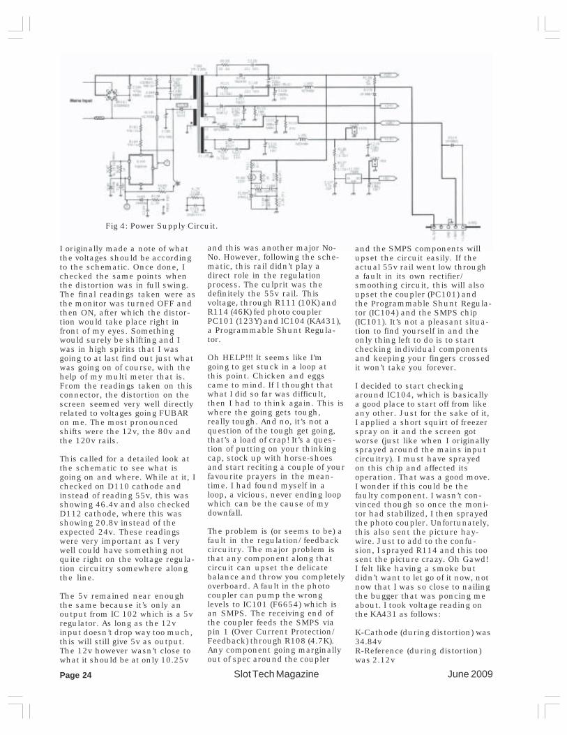
I originally made a note of whatthe voltages should be accordingto the schematic. Once done, Ichecked the same points whenthe distortion was in full swing.The final readings taken were asthe monitor was turned OFF andthen ON, after which the distor-tion would take place right infront of my eyes. Somethingwould surely be shifting and Iwas in high spirits that I wasgoing to at last find out just whatwas going on of course, with thehelp of my multi meter that is.From the readings taken on thisconnector, the distortion on thescreen seemed very well directlyrelated to voltages going FUBARon me. The most pronouncedshifts were the 12v, the 80v andthe 120v rails.
This called for a detailed look atthe schematic to see what isgoing on and where. While at it, Ichecked on D110 cathode andinstead of reading 55v, this wasshowing 46.4v and also checkedD112 cathode, where this wasshowing 20.8v instead of theexpected 24v. These readingswere very important as I verywell could have something notquite right on the voltage regula-tion circuitry somewhere alongthe line.
The 5v remained near enoughthe same because it’s only anoutput from IC 102 which is a 5vregulator. As long as the 12vinput doesn’t drop way too much,this will still give 5v as output.The 12v however wasn’t close towhat it should be at only 10.25v
and this was another major No-No. However, following the sche-matic, this rail didn’t play adirect role in the regulationprocess. The culprit was thedefinitely the 55v rail. Thisvoltage, through R111 (10K) andR114 (46K) fed photo couplerPC101 (123Y) and IC104 (KA431),a Programmable Shunt Regula-tor.
Oh HELP!!! It seems like I’mgoing to get stuck in a loop atthis point. Chicken and eggscame to mind. If I thought thatwhat I did so far was difficult,then I had to think again. This iswhere the going gets tough,really tough. And no, it’s not aquestion of the tough get going,that’s a load of crap! It’s a ques-tion of putting on your thinkingcap, stock up with horse-shoesand start reciting a couple of yourfavourite prayers in the mean-time. I had found myself in aloop, a vicious, never ending loopwhich can be the cause of mydownfall.
The problem is (or seems to be) afault in the regulation/feedbackcircuitry. The major problem isthat any component along thatcircuit can upset the delicatebalance and throw you completelyoverboard. A fault in the photocoupler can pump the wronglevels to IC101 (F6654) which isan SMPS. The receiving end ofthe coupler feeds the SMPS viapin 1 (Over Current Protection/Feedback) through R108 (4.7K).Any component going marginallyout of spec around the coupler
and the SMPS components willupset the circuit easily. If theactual 55v rail went low througha fault in its own rectifier/smoothing circuit, this will alsoupset the coupler (PC101) andthe Programmable Shunt Regula-tor (IC104) and the SMPS chip(IC101). It’s not a pleasant situa-tion to find yourself in and theonly thing left to do is to startchecking individual componentsand keeping your fingers crossedit won’t take you forever.
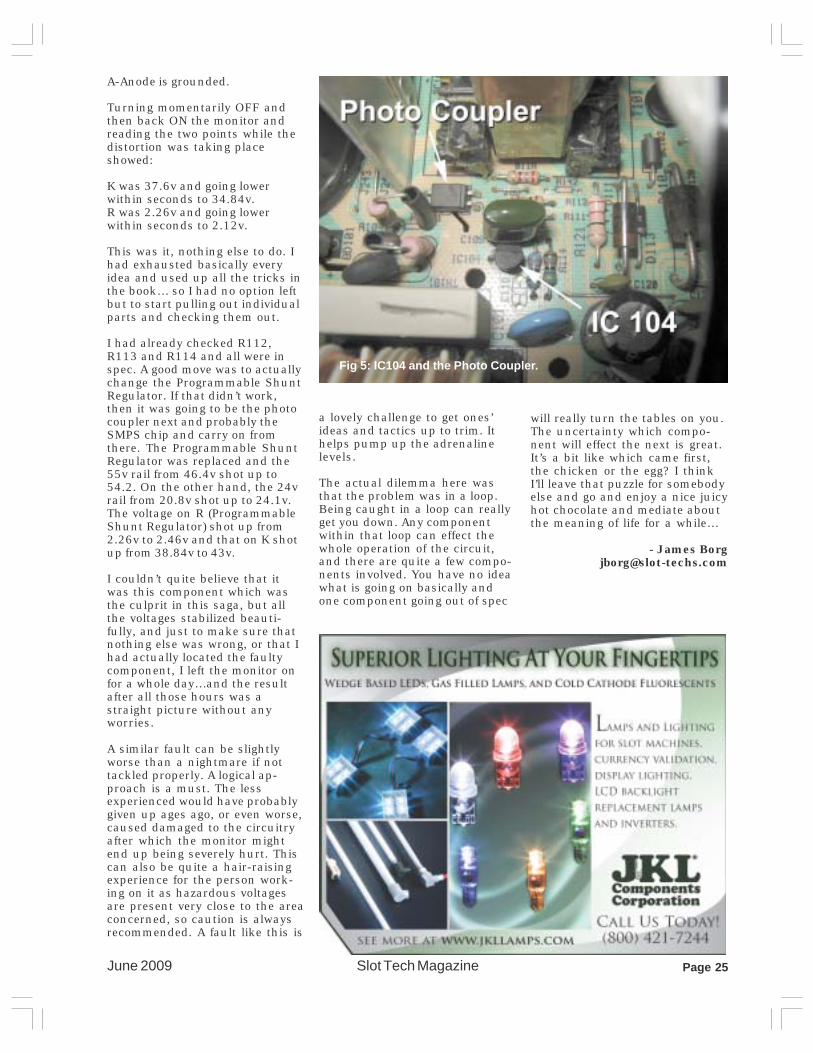
I decided to start checkingaround IC104, which is basicallya good place to start off from likeany other. Just for the sake of it,I applied a short squirt of freezerspray on it and the screen gotworse (just like when I originallysprayed around the mains inputcircuitry). I must have sprayedon this chip and affected itsoperation. That was a good move.I wonder if this could be thefaulty component. I wasn’t con-vinced though so once the moni-tor had stabilized, I then sprayedthe photo coupler. Unfortunately,this also sent the picture hay-wire. Just to add to the confu-sion, I sprayed R114 and this toosent the picture crazy. Oh Gawd!I felt like having a smoke butdidn’t want to let go of it now, notnow that I was so close to nailingthe bugger that was poncing meabout. I took voltage reading onthe KA431 as follows:
K-Cathode (during distortion) was34.84vR-Reference (during distortion)was 2.12v
Fig 4: Power Supply Circuit.
Slot Tech MagazineJune 2009 Page 25
A-Anode is grounded.
Turning momentarily OFF andthen back ON the monitor andreading the two points while thedistortion was taking placeshowed:
K was 37.6v and going lowerwithin seconds to 34.84v.R was 2.26v and going lowerwithin seconds to 2.12v.
This was it, nothing else to do. Ihad exhausted basically everyidea and used up all the tricks inthe book… so I had no option leftbut to start pulling out individualparts and checking them out.
I had already checked R112,R113 and R114 and all were inspec. A good move was to actuallychange the Programmable ShuntRegulator. If that didn’t work,then it was going to be the photocoupler next and probably theSMPS chip and carry on fromthere. The Programmable ShuntRegulator was replaced and the55v rail from 46.4v shot up to54.2. On the other hand, the 24vrail from 20.8v shot up to 24.1v.The voltage on R (ProgrammableShunt Regulator) shot up from2.26v to 2.46v and that on K shotup from 38.84v to 43v.
I couldn’t quite believe that itwas this component which wasthe culprit in this saga, but allthe voltages stabilized beauti-fully, and just to make sure thatnothing else was wrong, or that Ihad actually located the faultycomponent, I left the monitor onfor a whole day…and the resultafter all those hours was astraight picture without anyworries.
A similar fault can be slightlyworse than a nightmare if nottackled properly. A logical ap-proach is a must. The lessexperienced would have probablygiven up ages ago, or even worse,caused damaged to the circuitryafter which the monitor mightend up being severely hurt. Thiscan also be quite a hair-raisingexperience for the person work-ing on it as hazardous voltagesare present very close to the areaconcerned, so caution is alwaysrecommended. A fault like this is
Fig 5: IC104 and the Photo Coupler.
a lovely challenge to get ones’ideas and tactics up to trim. Ithelps pump up the adrenalinelevels.
The actual dilemma here wasthat the problem was in a loop.Being caught in a loop can reallyget you down. Any componentwithin that loop can effect thewhole operation of the circuit,and there are quite a few compo-nents involved. You have no ideawhat is going on basically andone component going out of spec
will really turn the tables on you.The uncertainty which compo-nent will effect the next is great.It’s a bit like which came first,the chicken or the egg? I thinkI’ll leave that puzzle for somebodyelse and go and enjoy a nice juicyhot chocolate and mediate aboutthe meaning of life for a while…
- James [email protected]


June 2009Slot Tech MagazinePage 28
TOPPERS
Order 3 ways:Toll free phone: 888-289-4277Toll free fax: 800-593-4277Online: www.suzohapp.com
ask for a fullcolor catalog