jumping hills construction norm 2018 implementing ...€¦ · the safety of ski jumpers, officials...
TRANSCRIPT

JUMPING HILLS
CONSTRUCTION NORM 2018
Implementing Provisions for Art. 411 of the ICR Ski Jumping
Author: Hans-Heini Gasser (SUI)
EDITION NOVEMBER 2018
2
Table of Contents
Page
1. Preliminary Remarks 3
2. Geometric Elements of a Ski Jumping Hill 4
3. Classification of Hills 6
4. Components of a Hill 6
4.1 Inrun Profile 6
4.2 Knoll Profile 7
5. Definition of the Compensation Factors 8
6. Specifications that Underlie the Excel Program JUMP-3.5 8
6.1 Formulas and Units 8
6.2 Physical Limits 8
6.3 Biomechanical Limits 9
6.4 Geometric Parameters, Laws and Limits 9
7. Precision of the Parameters in the Hill Certificate 11
3
1. Preliminary Remarks
Jumping hills that are to be homologated by the FIS must be configured in compliance
with the requirements of the International Competition Rules (ICR) and the present
Construction Standard (Norm). Also for jumping hills that will not be homologated by
the FIS, it is advisable to apply the FIS standards.
The geometric elements of a jumping hills and the minimum requirements necessary for
the safety of ski jumpers, officials and spectators are specified in the International
Competition Rules (ICR) Volume III, Art. 410. They serve hill inspectors and competi-
tion management with the assessment and approval of a facility.
The Jumping Committee created this standard for the planning of a new installation or
for the conversion of an existing installation. It is aimed at engineers and architects who
are responsible for project planning. In contrast to the last issue from 2012, the detailed
description of mathematical operations has been omitted. They are presented in the as-
sociated Excel program JUMP-3.5 (Program).
The basis for the standards work is extensive investigations into the biomechanical and
physical processes during a ski jump. Particularly significant are the analysis of trajec-
tory recordings and the detection of forces occurring in the air. The jump committee is
updated through periodically scheduled surveys on the progress of ski jumpers and
changes in the equipment over time.
Dr. Hans-Heini Gasser, a member of the Jumping Hills subcommittee, has developed
the Excel program JUMP-3.5 through computer simulation of the trajectory and analy-
sis of the biomechanical processes on the inrun, take-off and landing. In the paper
"Grundlagen der Auslegung des Längsprofils einer Skisprungschanze” (Basics of a Ski
Jumping Hill’s longitudinal profile) 2018, he describes the geometric and physical fun-
damentals, as well as the safety aspects. This can be downloaded on the FIS Website.
The computer program leaves a number of parameters open for modification so that it is
possible to optimally adapt a longitudinal profile to the given terrain profile.
The program does not yet contain updated results on the influence of air pressure when
jumping on a flying hill, so for the time being the program cannot be used for ski flying
hills.
The Microsoft Excel program, JUMP-3.5, can be ordered by prepayment of CHF 1’500
from the International Ski Federation, CH-3653 Oberhofen,
e-Mail: [email protected]

4
2. Geometric Elements of a Ski Jumping Hill
See Illustration 1
Inrun:
As Highest start gate with a snow track
Ae Highest start gate with an ice track
B Lowest start gate
E1 Beginning of the transition curve
E2 End of the transition curve; beginning of the table
T Takeoff
e1s Length of the inrun from the highest start As to T with a snow track
e1e Length of the inrun from the highest start Ae to T with an ice track
e2 Length of the inrun from the lowest start B to T
es Length of the inrun from the lowest to the highest start
t Length of the table
Angle of the straight part of the inrun
Angle of the table
r1 Radius of the transition curve in E2
Landing Profile:
T Takeoff ( = base coordinates)
s Height of the table
P Beginning of the landing area
K Construction point
L End of the landing area
U End of the transition curve to the outrun
HS Nominal Size (Hill Size) of the hill as the distance between the takeoff and the
end of the landing area L
w Distance between the takeoff and the construction point K
h Difference in height between the takeoff and K (K-z)
n Horizontal distance between the takeoff and K (Kx)
Uz Difference in Height between the takeoff and the lowest point U (-Uz)
l1 Length of the curve P-K
l2 Length of the curve K-L
l Length of the curve of the landing area P-L
a Length of the outrun after U
ß0 Angle of the tangent of the knoll profile at the base of the takeoff
ßP Angle of the tangent at P
ß Angle of the tangent at K
ßL Angle of the tangent at L
rL Radius of the circular landing area
r2L Radius of the transition curve from L to U at L
r2 Radius of the transition curve from L to U at U
b1 Prepared width of the inrun
b2 Width of the knoll at the base of the takeoff
bK Width at K
bU Width at U
5
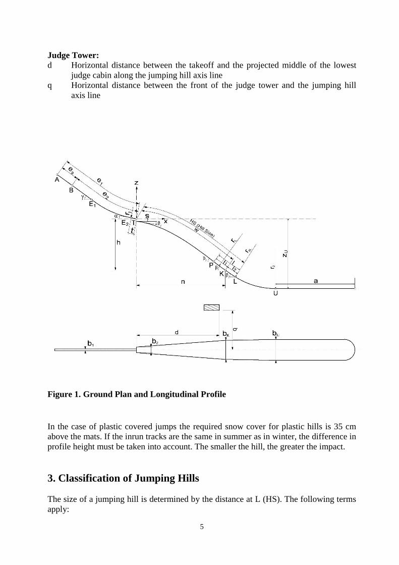
Judge Tower:
d Horizontal distance between the takeoff and the projected middle of the lowest
judge cabin along the jumping hill axis line
q Horizontal distance between the front of the judge tower and the jumping hill
axis line
Figure 1. Ground Plan and Longitudinal Profile
In the case of plastic covered jumps the required snow cover for plastic hills is 35 cm
above the mats. If the inrun tracks are the same in summer as in winter, the difference in
profile height must be taken into account. The smaller the hill, the greater the impact.
3. Classification of Jumping Hills
The size of a jumping hill is determined by the distance at L (HS). The following terms
apply:

6
Designation HS Associated Distance w
Small Hills 49 m and under 44 m and under
Middle Hills 50 m to 84 m 45 m to 75 m
Normal Hills 85 m to 109 m 76 m to 98 m
Large Hills 110 m to 145 m 99 m to 130 m
Flying Hills 185 m and over 166 m and over
Large hills with a difference in height between the lowest point on the outrun and the
takeoff of more than 88 m are not homologated by the FIS (ICR Article 411.1). If a
normal and a large hill are built in the same place, the difference in HS must be at least
25 meters.
4. Components of a Hill
4.1 Inrun
The inrun consists of a straight portion with an inclination followed by a clothoid-like
transitional curve with an end radius of r1 and a straight table with length t and inclina-
tion .
e1 is the inrun length from the highest start A to T (Figure 1), that is required for a
jumper to reach the K point with a tailwind of 3 m/s. There should be a distinction be-
tween an ice track and a snow track.
e2 is the inrun length from the lowest start B to T. This inrun length ensures that a good
jumper does not jump past L with a headwind of 4 m/s and a fast track.
The inrun length is the entire section of the profile from the point on the track perpen-
dicular to the start bar (Happle-Bar) to the takeoff edge.
es = e1 - e2 Start Area. The start gates in es must be arranged at equal intervals, where
the difference in height between two starts may not be greater than 0.40 m. They must
also be numbered consecutively, beginning with the number 1 at the lowest start.
The following applies for the table angle :
w/30 + 6.9 ≤ ≤ w/30 + 7.9.
The program calculates with = w/30 + 7.4. A larger means a lower height of the
flight curve, a smaller means a higher height of the flight curve. On a large hill with
HS 145, the use of a variance of -0.5° to +0.5° translates to heights from 3.3 m to 3.7
m.
7
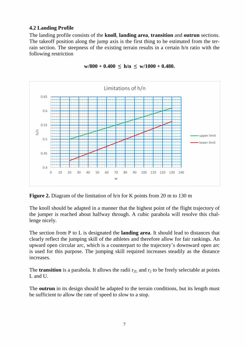
4.2 Landing Profile
The landing profile consists of the knoll, landing area, transition and outrun sections.
The takeoff position along the jump axis is the first thing to be estimated from the ter-
rain section. The steepness of the existing terrain results in a certain h/n ratio with the
following restriction
w/800 + 0.400 ≤ h/n ≤ w/1000 + 0.480.
Figure 2. Diagram of the limitation of h/n for K points from 20 m to 130 m
The knoll should be adapted in a manner that the highest point of the flight trajectory of
the jumper is reached about halfway through. A cubic parabola will resolve this chal-
lenge nicely.
The section from P to L is designated the landing area. It should lead to distances that
clearly reflect the jumping skill of the athletes and therefore allow for fair rankings. An
upward open circular arc, which is a counterpart to the trajectory’s downward open arc
is used for this purpose. The jumping skill required increases steadily as the distance
increases.
The transition is a parabola. It allows the radii r2L and r2 to be freely selectable at points
L and U.
The outrun in its design should be adapted to the terrain conditions, but its length must
be sufficient to allow the rate of speed to slow to a stop.
0.4
0.45
0.5
0.55
0.6
0.65
0 10 20 30 40 50 60 70 80 90 100 110 120 130 140
h/n
w
Limitations of h/n
upper limit
lower limit
8
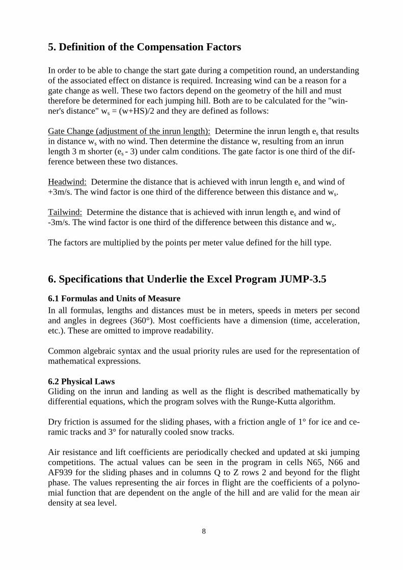
5. Definition of the Compensation Factors
In order to be able to change the start gate during a competition round, an understanding
of the associated effect on distance is required. Increasing wind can be a reason for a
gate change as well. These two factors depend on the geometry of the hill and must
therefore be determined for each jumping hill. Both are to be calculated for the "win-
ner's distance" ws = (w+HS)/2 and they are defined as follows:
Gate Change (adjustment of the inrun length): Determine the inrun length es that results
in distance ws with no wind. Then determine the distance w, resulting from an inrun
length 3 m shorter (es - 3) under calm conditions. The gate factor is one third of the dif-
ference between these two distances.
Headwind: Determine the distance that is achieved with inrun length es and wind of
+3m/s. The wind factor is one third of the difference between this distance and ws.
Tailwind: Determine the distance that is achieved with inrun length es and wind of
-3m/s. The wind factor is one third of the difference between this distance and ws.
The factors are multiplied by the points per meter value defined for the hill type.
6. Specifications that Underlie the Excel Program JUMP-3.5
6.1 Formulas and Units of Measure
In all formulas, lengths and distances must be in meters, speeds in meters per second
and angles in degrees (360°). Most coefficients have a dimension (time, acceleration,
etc.). These are omitted to improve readability.
Common algebraic syntax and the usual priority rules are used for the representation of
mathematical expressions.
6.2 Physical Laws
Gliding on the inrun and landing as well as the flight is described mathematically by
differential equations, which the program solves with the Runge-Kutta algorithm.
Dry friction is assumed for the sliding phases, with a friction angle of 1° for ice and ce-
ramic tracks and 3° for naturally cooled snow tracks.
Air resistance and lift coefficients are periodically checked and updated at ski jumping
competitions. The actual values can be seen in the program in cells N65, N66 and
AF939 for the sliding phases and in columns Q to Z rows 2 and beyond for the flight
phase. The values representing the air forces in flight are the coefficients of a polyno-
mial function that are dependent on the angle of the hill and are valid for the mean air
density at sea level.

9
Wind influence is considered under the simplifying assumption that it remains constant
for the entire distance of the flight.
6.3 Biomechanical Limits
Speed and direction from the takeoff are the initial conditions of the trajectory. The di-
rection is determined by the inclination of the table and the velocity component v┴
from the jumping motion. The value v┴ is subject to change and differs according to the
class of the jumpers and the type of hill. The currently effective values can be viewed in
the program in cells AA3 and beyond.
When landing, the jumper experiences an impact that can be quantified with the equiva-
lent landing height (e.LH). The impact is compared to the impact of dropping from the
e.LH onto a horizontal landing surface. When landing at the K-point this impact should
be gentle (comfortable landing height); a limit is reached at the L-point beyond which a
safe landing is no longer guaranteed. Based on many years of experience and athlete
trials in 2016, the e.LH was determined. The values are stored in the cells AB3/AC3
and following.
Jumpers experience a centrifugal force in the transition areas of the inrun and outrun.
This may not exceed 70% of the jumper’s weight at point E2 and 80% of the jumper’s
weight between L and U.
6.4 Geometric Parameters and Directional & Limit Values
The inrun angle may not exceed 37°, but it is recommended that it not exceed 35°. For
jumping hills where w ≥ 90, should be at least 30° and for jumping hills where w <90
at least 25°. For beginners' hills where w <30, should not exceed 32°.
The distance of a point of the landing profile from the takeoff edge T is defined in ICR
Art. 415.1. The program calculates it with the approximation formula
w = 1.005*[T-P],
where [T-P] means the oblique distance of T and P.
The initial parameters for a jumping hill are the distance w to the point K, and the
steepness expressed by the ratio h/n (see Figure 1).
The two variables w and h/n are for the most part freely selectable. However, decades
of experience with jumping hills of all sizes has limited this freedom. See Section 4.2
and Figure 2. From these two parameters, the position of the K point can be calculated.
With the selection of a table angle , the jump speed v0, at which the jumper reaches the
K point in calm weather, is also determined. The profile angle is determined by the
e.LH permitted at the K point.
10
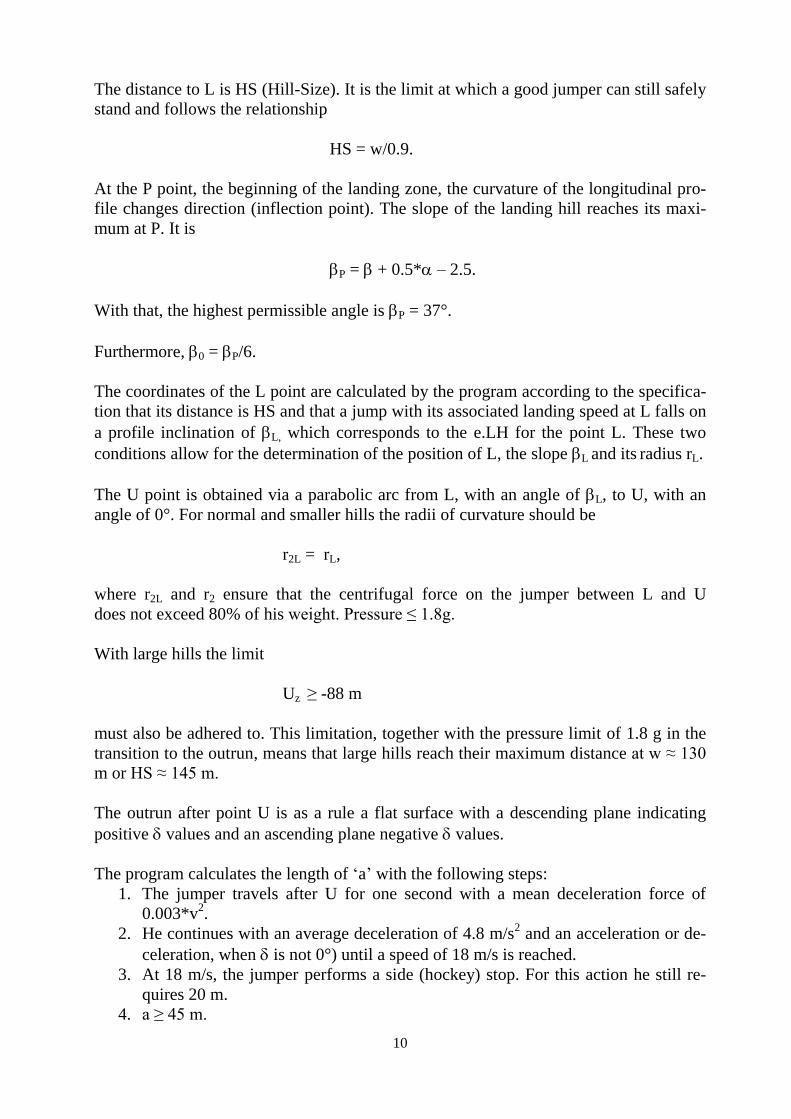
The distance to L is HS (Hill-Size). It is the limit at which a good jumper can still safely
stand and follows the relationship
HS = w/0.9.
At the P point, the beginning of the landing zone, the curvature of the longitudinal pro-
file changes direction (inflection point). The slope of the landing hill reaches its maxi-
mum at P. It is
P = + 0.5* – 2.5.
With that, the highest permissible angle is P = 37°.
Furthermore, 0 = P/6.
The coordinates of the L point are calculated by the program according to the specifica-
tion that its distance is HS and that a jump with its associated landing speed at L falls on
a profile inclination of L, which corresponds to the e.LH for the point L. These two
conditions allow for the determination of the position of L, the slope L and its radius rL.
The U point is obtained via a parabolic arc from L, with an angle of L, to U, with an
angle of 0°. For normal and smaller hills the radii of curvature should be
r2L = rL,
where r2L and r2 ensure that the centrifugal force on the jumper between L and U
does not exceed 80% of his weight. Pressure ≤ 1.8g.
With large hills the limit
Uz ≥ -88 m
must also be adhered to. This limitation, together with the pressure limit of 1.8 g in the
transition to the outrun, means that large hills reach their maximum distance at w ≈ 130
m or HS ≈ 145 m.
The outrun after point U is as a rule a flat surface with a descending plane indicating
positive values and an ascending plane negative values.
The program calculates the length of ‘a’ with the following steps:
1. The jumper travels after U for one second with a mean deceleration force of
0.003*v2.
2. He continues with an average deceleration of 4.8 m/s2 and an acceleration or de-
celeration, when is not 0°) until a speed of 18 m/s is reached.
3. At 18 m/s, the jumper performs a side (hockey) stop. For this action he still re-
quires 20 m.
4. a ≥ 45 m.
11
For summer use with a grass outrun ‘a’ should be increased by 15 m.
The program calculates a according to these specifications. If the outrun follows as a
curved (non-flat) surface, calculate the outrun length in the phases described by a nu-
merical algorithm.
The position of the judge tower (see Figure 1) is restricted by the limits
d = 0.60w to 0.80w
q = 0.25w to 0.50w.
The height of the judge cabins should be determined in such a way that the judges’ view
of the jumper is guaranteed in his flight from the edge of the takeoff to at least the fall
line. In assessing this, crash barriers, slope edges and any mechanical climbing aids be-
tween the judge tower and the jumping hill need to be considered.
Further guidelines and limits are listed in ICR Art. 411.4 and 411.5.
7. Precision of the Parameters in the Hill Certificate
Curvature Radii to the nearest Meter
Lengths to the cm
Angles to one tenth of a degree
Velocities to two decimal places
h/n to three decimal places