jumo-dtherm-m digital indicator · jumo-dtherm-m digital indicator with integrated 2-wire...
TRANSCRIPT

JUMO-dTHERM-MDigital Indicatorwith integrated
2-wiretransmitter
Series 8624
B 60.8624.0Operating Instructions
08.01 / 00396481

0
Typographical conventions
Warnings The signs for Danger and Caution are used in these Operating Instruc-tions under the following conditions:
DangerThis sign is used when there may be danger to personnel if the instruc-tions are disregarded or not followed accurately.
CautionThis sign is used when there may be damage to equipment or data if the instructions are disregarded or not followed accurately.
Note signs
NoteThis sign is used when your attention is drawn to a specific remark.
ReferenceThis sign refers to further information in other operating instructions, chapters or sections.
ActionThis sign indicates that an action to be performed is described.
The individual steps are marked by an asterisk, e.g.
Press the key
1
Contents
Page1 General........................................................................................................................ 2
2 Installation .................................................................................................................. 2
2.1 Preparing the installation ............................................................................................ 32.2 Installation notes.......................................................................................................... 32.3 Fitting in position ......................................................................................................... 3
3 Electrical connection................................................................................................. 4
3.1 Assembling the connector ........................................................................................... 43.2 Assembling the terminal box ....................................................................................... 53.3 Connection diagram .................................................................................................... 6
4 Block diagram ............................................................................................................ 7
4.1 Function ...................................................................................................................... 7
5 Technical data ........................................................................................................... 8
6 Maintenance / Fault ................................................................................................... 9
2
1 General
Please read these Operating Instructions before commissioning the in-strument. Keep the manual in a place which is accessible to all users at all times. Please assist us to improve these operating instructions where necessary. Your suggestions will be welcome.
Phone (+49) 661 6003-0Fax (+49) 661 6003-607
NoteIf any difficulties should arise during commissioning, you are asked not to carry out any unauthorized manipulations on the unit. You could endanger your rights under the instrument warranty! Please contact the supplier or the main factory.
2 Installation
2.1 Preparing the installation
Determine the instrument version by the nameplate, the type designation or the type extensions (extra codes).
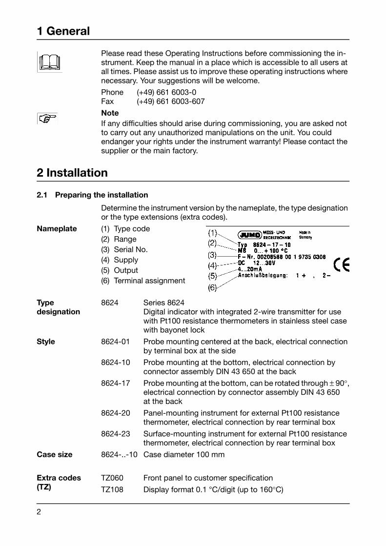
Nameplate (1) Type code(2) Range(3) Serial No.(4) Supply(5) Output(6) Terminal assignment
Typedesignation
8624 Series 8624Digital indicator with integrated 2-wire transmitter for use with Pt100 resistance thermometers in stainless steel case with bayonet lock
Style 8624-01 Probe mounting centered at the back, electrical connection by terminal box at the side
8624-10 Probe mounting at the bottom, electrical connection byconnector assembly DIN 43 650 at the back
8624-17 Probe mounting at the bottom, can be rotated through ± 90°,electrical connection by connector assembly DIN 43 650at the back
8624-20 Panel-mounting instrument for external Pt100 resistance thermometer, electrical connection by rear terminal box
8624-23 Surface-mounting instrument for external Pt100 resistance thermometer, electrical connection by rear terminal box
Case size 8624-..-10 Case diameter 100 mm
Extra codes(TZ)
TZ060 Front panel to customer specification
TZ108 Display format 0.1 °C/digit (up to 160°C)

3
Installation
2.2 Installation notes
The ambient temperature at the installation site must be within the range 0 to +60°C. Thermal conduction from the probe must not cause the case temperature to go above the permitted ambient temperature range.
For measured values above 200°C, we recommend the use of styles 20 or 23 (with external Pt100 resistance thermometer ).
Do not allow any magnetic or electric fields, such as those caused by transformers, mobile phones or electrostatic discharge, in the vicinity of the instrument.
All input and output lines that are not connected to the mains supply must be laid as shielded and twisted cables. The shielding must be grounded on the instrument side.
Do not install the unit close to power components or cables. Earth the shield at one side on the instrument.
2.3 Fitting in position
On styles 01, 10 and 17, the probe mounting is secured by simplytightening up the screw fitting or the union nut with a wrench.
Although the operating position is generally unrestricted, it is limited by the visibility of the display.On style 17, the probe mounting can be rotated through ± 90°.The protection rating given will only be achieved if the connector orterminal box is assembled correctly.
Caution
Earth the case!
4
3 Electrical connection
3.1 Assembling the connector
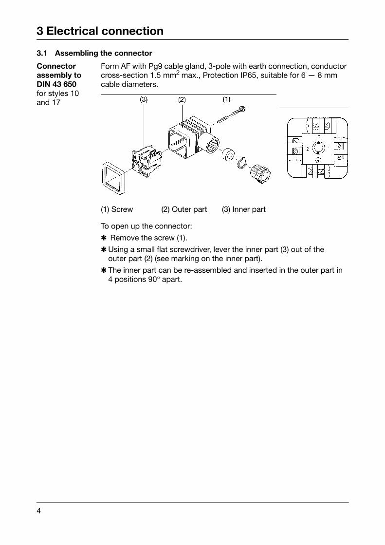
Connectorassembly toDIN 43 650for styles 10and 17
Form AF with Pg9 cable gland, 3-pole with earth connection, conductor cross-section 1.5 mm2 max., Protection IP65, suitable for 6 — 8 mmcable diameters.
To open up the connector:
Remove the screw (1).
Using a small flat screwdriver, lever the inner part (3) out of theouter part (2) (see marking on the inner part).
The inner part can be re-assembled and inserted in the outer part in4 positions 90° apart.
(1) Screw (2) Outer part (3) Inner part

5
Electrical connection
3.2 Assembling the terminal box
Terminal boxfor styles 01, 20 and 23
6-pole with earth terminal, conductor cross-section 2.5 mm2 max.,Protection IP65, Pg13.5 cable gland, and (depending on the cable type) suitable for:
– 1 cable with 6.5 — 13 mm dia. (style 01)
– 2 cables with with 3 — 5 mm dia. (styles 20 and 23)
To open the terminal box:
Unscrew cover screw (1)
Remove cover (2) and middle part (8)
When re-assembling, the middle part (8) can be mounted in theopposite direction.
(1) Cover screw (captive) (7) Cage clamp(2) Cover (8) Middle part(3) Sealing ring (9) Gasket(4) Screw-in bush (10) Lower part(5) Pressure washer (11) Flat seal(6) Compression ring
6
Electrical connection
3.3 Connection diagram
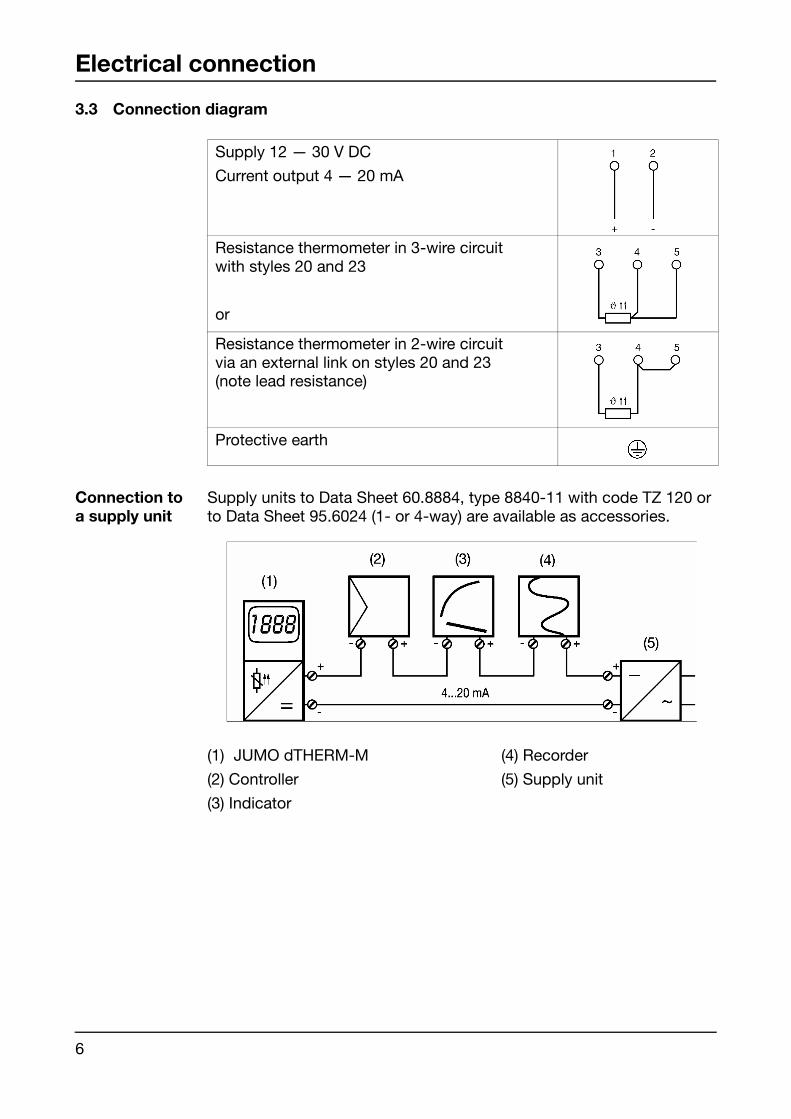
Connection to a supply unit
Supply units to Data Sheet 60.8884, type 8840-11 with code TZ 120 or to Data Sheet 95.6024 (1- or 4-way) are available as accessories.
Supply 12 — 30 V DC
Current output 4 — 20 mA
Resistance thermometer in 3-wire circuitwith styles 20 and 23
or
Resistance thermometer in 2-wire circuitvia an external link on styles 20 and 23(note lead resistance)
Protective earth
(1) JUMO dTHERM-M (4) Recorder
(2) Controller (5) Supply unit
(3) Indicator
7
4 Block diagram
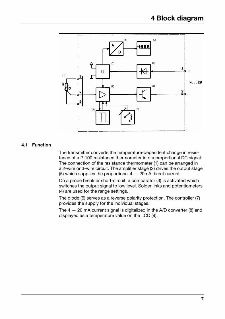
4.1 Function
The transmitter converts the temperature-dependent change in resis-tance of a Pt100 resistance thermometer into a proportional DC signal. The connection of the resistance thermometer (1) can be arranged ina 2-wire or 3-wire circuit. The amplifier stage (2) drives the output stage (5) which supplies the proportional 4 — 20mA direct current.
On a probe break or short-circuit, a comparator (3) is activated which switches the output signal to low level. Solder links and potentiometers (4) are used for the range settings.
The diode (6) serves as a reverse polarity protection. The controller (7) provides the supply for the individual stages.
The 4 — 20 mA current signal is digitalized in the A/D converter (8) and displayed as a temperature value on the LCD (9).
8
5 Technical data
Ranges -50 to +50°C *0 to +100°C *0 to +120°C *0 to +160°C *0 to +200°C *
-50 to +200°C *0 to +400°C * 0 to +600°C *
on request in °F* standard ranges
For measurements above 200°C, we recommend the use of styles 20 or 23 (with external Pt100 resistance thermometer ).
Case stainless steel, Mat. Ref. 1.4301aluminium angle block (for style 17)
Bezel or flange stainless steel, Mat. Ref. 1.4301
Measurementinput
Pt100 resistance thermometer in 3-wire circuit on styles 20 and 23.A 2-wire circuit without lead compensation can be implemented via an external link between terminals 4 and 5.
Display 31/2-digit LCD, digit height 13 mm
Transfercharacteristic
linear with temperature
Linearityerror
≤ 0.2% of full scale
Calibrationaccuracy
≤ 0.5% of full scale
Indicationaccuracy
≤ 0.2% of full scale ± 1 digit
Display format standard: 1 °C with code TZ108: 0.1 °C
Supply 12 — 30 V DC; nominal value 24 V DC
Max. currentconsumption
approx. 30 mA
9
Technical data
Supply voltageerror
≤ 0.02% of measuring span per volt deviation from 24 V DC
Output signal 4 — 20 mA
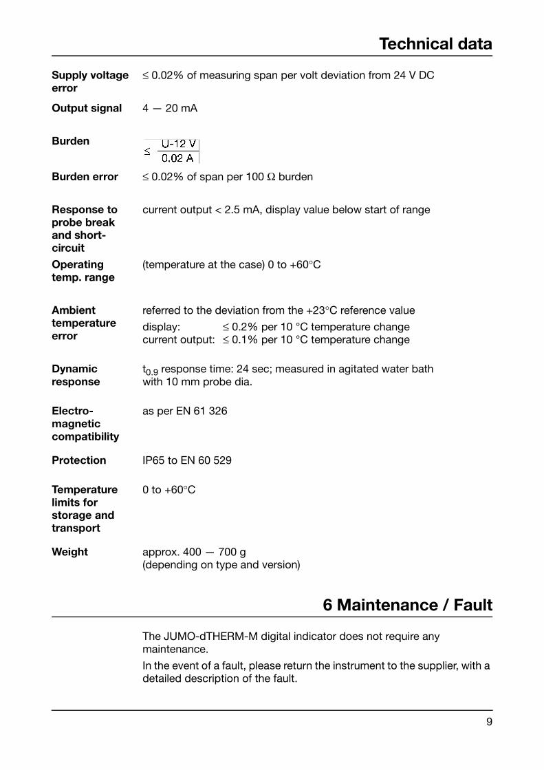
Burden
Burden error ≤ 0.02% of span per 100 Ω burden
Response toprobe break and short-circuit
current output < 2.5 mA, display value below start of range
Operatingtemp. range
(temperature at the case) 0 to +60°C
Ambienttemperatureerror
referred to the deviation from the +23°C reference value
display: ≤ 0.2% per 10 °C temperature changecurrent output: ≤ 0.1% per 10 °C temperature change
Dynamicresponse
t0.9 response time: 24 sec; measured in agitated water bathwith 10 mm probe dia.
Electro-magneticcompatibility
as per EN 61 326
Protection IP65 to EN 60 529
Temperaturelimits for storage andtransport
0 to +60°C
Weight approx. 400 — 700 g(depending on type and version)
6 Maintenance / Fault
The JUMO-dTHERM-M digital indicator does not require anymaintenance.
In the event of a fault, please return the instrument to the supplier, with a detailed description of the fault.

M. K. JUCHHEIM GmbH & CoStreet address:Moltkestraße 13 - 3136039 Fulda, GermanyDelivery address:Mackenrodtstraße 1436039 Fulda, GermanyPostal address:36035 Fulda, GermanyPhone: +49 661 60 03-0Fax: +49 661 60 03-6 07E-mail: [email protected]: www.jumo.de
JUMO Instrument Co. Ltd.JUMO HouseTemple Bank, RiverwayHarlow, Essex CM20 2TT, UK
Phone: +44 12 79 63 55 33Fax: +44 12 79 63 52 62E-mail: [email protected]
JUMO PROCESS CONTROL INC.885 Fox Chase, Suite 103Coatesville, PA 19320, USAPhone: 610-380-8002
1-800-554-JUMOFax: 610-380-8009E-mail: [email protected]: www.JumoUSA.com