july 1998 alerts - federal aviation administration · ac no. 43-16a alert no. 240 july 1998 improve...
TRANSCRIPT
AviationMaintenanceAlerts
AC No. 43-16A
ALERT NO. 240JULY 1998
Improve Reliability-Interchange ServiceExperience
A LER TS

Contents of this publication are informational only. Due to the need for extensive distribution of this publication,only one copy is provided to an addressee; however, this publication may be duplicated.
CONTENTS
NEWS
CHANGES TO THIS PUBLICATION ................................................................................. 1
AIRPLANES
BEECH................................................................................................................................... 2BELLANCA ........................................................................................................................... 4CESSNA ................................................................................................................................. 5LAKE ...................................................................................................................................... 9LUSCOMBE........................................................................................................................... 9PIPER .................................................................................................................................. 10SOCATA ............................................................................................................................... 12
HELICOPTERS
AGUSTA............................................................................................................................... 13BELL .................................................................................................................................... 14McDONNELL DOUGLAS ................................................................................................... 16
AMATEUR, EXPERIMENTAL, AND SPORT AIRCRAFT
AVIAT .................................................................................................................................. 16KIST ..................................................................................................................................... 17PITTS ................................................................................................................................... 18THORPE .............................................................................................................................. 18VANS .................................................................................................................................... 18
POWERPLANTS AND PROPELLERS
ALLISON ............................................................................................................................. 20PRATT & WHITNEY .......................................................................................................... 20
AIR NOTES
AIRWORTHINESS DIRECTIVES (AD’S) ISSUED IN MAY 1998 .................................. 21NEW TEST FOR EXHAUST SYSTEM METAL................................................................ 21AVIATION SAFETY PROGRAM MANAGER AIRWORTHINESS ................................. 23SUSPECTED UNAPPROVED PART (SUP) SEMINAR................................................... 24IF YOUR ADDRESS CHANGES ........................................................................................ 25IF YOU WANT TO CONTACT US ..................................................................................... 25FAA FORM 8010-4, MALFUNCTION OR DEFECT REPORT ........................................ 26SUBSCRIPTION REQUEST FORM .................................................................................. 26

July 1998 FAA AC 43-16A
1
U.S. DEPARTMENT OF TRANSPORTATION
FEDERAL AVIATION ADMINISTRATION
WASHINGTON, DC 20590
AVIATION MAINTENANCE ALERTS
The Aviation Maintenance Alerts provide a common communication channel through which the aviation community caneconomically interchange service experience and thereby cooperate in the improvement of aeronautical product durability,reliability, and safety. This publication is prepared from information submitted by those who operate and maintain civilaeronautical products. The contents include items that have been reported as significant, but which have not been evaluated fullyby the time the material goes to press. As additional facts such as cause and corrective action are identified, the data will be publishedin subsequent issues of the Alerts. This procedure gives Alerts’ readers prompt notice of conditions reported via Malfunction orDefect Reports. Your comments and suggestions for improvement are always welcome. Send to: FAA; ATTN: DesigneeStandardization Branch (AFS-640); P.O. Box 25082; Oklahoma City, OK 73125-5029.
NEWS
CHANGES TO THIS PUBLICATION
To improve the quality of this publication, we have made some changes which reflect the highstandards and professionalism of our readers.
The title of the publication has been changed to “AC 43-16A, Aviation Maintenance Alerts.” Thenew title enables us to publish information concerning any aviation product.
We added color to enhance readability and provide clarity to photographs. When possible, weinvite you to send color photographs with your report.
We encourage you to submit maintenance information, so we can disseminate it to the aviationpublic via this publication. In the past, readers have discovered potentially dangerous safetydefects because they read about it in this publication. When you submit reports, you aresupporting the system and making it better.
We have created a new Internet web site which includes an electronic version ofFAA Form 8010-4, Malfunction or Defect (M or D) Report. You may use the electronic version tosend M or D reports to us.
The web site also includes a search function for older copies of the Alerts. Currently, we havetwelve issues available on the web site. As time permits, we will continue to add more issues.
In the future, we will establish an E-Mail distribution system for the publication. When thatsystem is in place, we will strongly urge you to use this system. The system will save printingand mailing costs associated with delivering paper copies. If you switch to the E-Mail
FAA AC 43-16A July 1998
2
distribution system, please tell us by using the subscription form in the back of this edition. Wewill delete your name from the paper copy distribution list. We will continue to print papercopies for those who do not have access to the Internet and E-Mail.
The address for this web site is:
http://www.mmac.jccbi.gov/alerts/
If you like the idea of receiving the Alerts via E-Mail, please let us know so that we can get anidea of how many of our readers will take advantage of this system. You may contact Phil Lomaxby mail, telephone, or FAX.
Mailing address: FAA ATTN: AFS-640 ALERTS P.O. Box 25082 Oklahoma City, OK 73125-5029
Telephone: (405) 954-6487FAX: (405) 954-4570 or (405) 954-4748
We value your opinion and welcome any questions, comments, or ideas you may have regardingthis publication. If you find something you like, tell us and someone else. If you find somethingyou do not like, tell us—we will fix it.
Thanks to all of you who have supplied information for this publication over the years. By doingso, you make that information, as well as your experience, available to the entire aviationcommunity. Keep up the good work.
AIRPLANES
BEECH
Beech; Model S-35; Bonanza; Fuel Quantity Errors; ATA 2842
A Beech fuel quantity transmitter kit (P/N 55-9018-18) was installed on this aircraft. Afterinstallation, several repetitive errors and malfunctions were experienced.
The aircraft fuel system uses two quantity probes in each wing tank. The outboard fuel quantitytransmitters had a failure rate of approximately 100 hours of operation. The problems usuallyoccurred with full fuel tanks. The fuel quantity indicator needle began to “flicker,” and within15 minutes, the needle dropped to a one-quarter tank indication. All four transmitters exhibitedthese same characteristics. The fuel quantity transmitters were bench checked and wereconfirmed to be the source of the problem.
Part total time not applicable.

July 1998 FAA AC 43-16A
3
Beech; Model A-36; Bonanza; Nose Landing Gear Retraction Defect; ATA 3230
During a landing approach, the nose landing gear failed to extend. All attempts to lower thenose gear failed, and a landing was made with the nose gear in an intermediate position.
An investigation revealed that the aft extension/retraction tube (P/N 36-820011-3) ends werebroken and bent into a “C” shape. The tube had been installed backward which resulted in theincorrect style rod-end being attached to the gear box arm of the landing gear. The rod-endsthat were attached to each end of the extension/retraction tube are different types; therefore,they should not be interchanged. The forward rod-end, attached to the idler arm(P/N 35-820094-2), is designed for fore-and-aft movement, and the rod-end attached to the gearbox is designed for rotational and fore-and-aft movement.
By installing the extension/retraction tube backward, side pressure cracked the rod-end bearingcase which allowed the bearing to separate from the rod-end case.
Part total time-5,343 hours.
Beech; Model A-36; Bonanza; Hydraulic Brake Line Wear; ATA 3242
While installing avionics equipment, the technician noticed the right rudder control cable waschafing on a wheel brake hydraulic line.
This aircraft was manufactured in 1997 and had very low operating time; however, the ruddercable had already cut into a parking brake hydraulic line. The parking brake hydraulic assemblyis located beneath the floor boards on the pilot’s side. It was necessary to adjust the bend radiusof the line where it enters the parking brake block assembly to provide adequate clearance fromthe rudder cable. Also, the line was wrapped with chafe-protection material.
It was suggested that the manufacturer consider relocating the parking brake assembly 1 inchto the right to prevent interference with other components.
Part total time-26 hours.
Beech; Model A-60; Duke; Defective Instrument Plumbing; ATA 7713
During takeoff, the rated engine manifold pressure (MAP) could not be attained. Whileclimbing, the MAP began to decline at a higher rate than normal. A safe landing was made, andthe aircraft was delivered to maintenance.
The technician checked the engine intake and exhaust systems and the controller withoutfinding the cause of the defect. When the manifold pressure hoses were inspected, the hosesystem failed to hold pressure during a test. The hoses appeared to be in good condition;however, when the fire sleeve was pulled back, the steel braided hose (P/N 96-910004-19)disintegrated.
Research indicated that this hose was installed as original equipment in 1973. These pneumatichoses should be replaced during each engine change or after 5 years of service.
Part total time-2,360 hours.
FAA AC 43-16A July 1998
4
Beech; Model B-95; Travel Air; Wing and Nacelle Skin Chafing; ATA 5414
During an annual inspection, it was found that the lower aft nacelle skin was chafing the wingskin. This defect was found on both nacelles.
The nacelle skin had worn completely through the wing skin behind both engines. This area waslocated just aft of the front wing spar flange. If this condition had not been found and corrected,it could have worn into the spar flange.
It was suggested that the manufacturer design a chafe strip to be installed between thesecomponents.
Part total time-6,500 hours.
Beech; Model 200; King Air; Defective Automatic Trim Relay; ATA 2700
After the flight control trim system failed, the aircraft was taken to maintenance for repair.
Tests and inspection of the trim system disclosed that the automatic flight control trim relayassembly (P/N 101-500038-5) was not operating properly. When a new assembly was installed,both the manual and automatic flight control trim systems ran backwards. Evidently, the relaycircuit board had been improperly wired. Also, the incorrect gender fasteners had beeninstalled on the relay (female fasteners instead of male fasteners).
Part total time-0 hours.
Beech; Model 200; King Air; Landing Gear Wheel Defect; ATA 3246
During nondestructive testing, a wheel half (P/N 40-172) was found cracked.
This crack was approximately 1.25 inches long and was unnoticed during the visual check. Thecrack was located at the inboard tangent of the bead radius. It was speculated that the wheelassembly was in danger of imminent failure.
If this had not been found, it could have resulted in a catastrophic part failure which may haveresulted in an accident.
Part total time-5,230 hours.
BELLANCA
Bellanca; Model 8GCBC; Defective Wing Flap Cables; ATA 2750
During an annual inspection, the technician discovered broken strands on the left and rightwing flap control cables. The flap cables (P/N 1-9023) were damaged where they passed over apulley at the left and right wing roots.

July 1998 FAA AC 43-16A
5
Five years earlier, the left flap cable broke and was replaced. The submitter speculated that thebroken strands may have been caused by the “stiff cable passing over a small diameter pulley.”
This area should be thoroughly inspected during schedule inspections and maintenance.
Part total time-800 hours.
CESSNA
Cessna; Model 172M; Skyhawk; Electrical System Short Circuit; ATA 2421
While troubleshooting the cause of an electrical short circuit, the alternator wire bundle wasfound chafed.
The rubber cushion on three “Adel” clamps had been worn through by the metal braiding on theoutside of some of the wires in the alternator wire bundle. The wires were then chafed by themetal band of the “Adel” clamp causing the wire insulation to melt and burn. If this defectoccurred during flight, the results may have been catastrophic.
The “Adel” clamps should be replaced as soon as they show early signs of deterioration. Whensafety is concerned, use quality parts.
Part total time-4,207 hours.
Cessna; Model 172P; Skyhawk; Aileron Cable Damage; ATA 2710
While complying with the requirements of Cessna Service Bulletin (SB) 97-1, the right aileroncable was found severely damaged.
The aileron cable (P/N 0510105-260) was frayed at the point where it passes under the rightoutboard pulley located at the lower aft doorframe. This area is very difficult to see duringroutine inspections. The frayed area was visible after the pulley was removed. During theinitial inspection, eight strands of the cable were found broken.
The submitter recommended that the pulleys be removed, at least, every 5,000 hours tofacilitate a close inspection of the aileron cables.
Part total time-11,700 hours.
Cessna; Model 172RG; Cutlass; Main Landing Gear Failure; ATA 3230
While the pilot was practicing landings, the left main landing gear failed to extend. After manyemergency extension attempts, the gear was secured in the “down-and-locked” position, and anuneventful landing was made. This aircraft was operated by flight school personnel.
The technician removed the left main landing gear pivot assembly (P/N 2441100-3F) anddiscovered it was broken. The failure occurred at the drive spline radius. The submitter did notoffer a cause for this defect. The right main landing gear pivot assembly was removed andchecked for damage. A crack was found at the same location as the left main landing gear pivotassembly.
FAA AC 43-16A July 1998
6
Both pivot assemblies were replaced in accordance with Cessna Service Bulletin 90-1,Revision 2.
Part total time-4,120 hours.
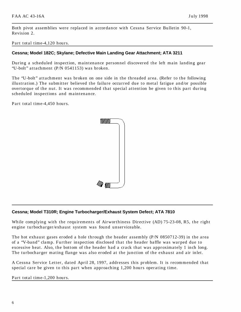
Cessna; Model 182C; Skylane; Defective Main Landing Gear Attachment; ATA 3211
During a scheduled inspection, maintenance personnel discovered the left main landing gear“U-bolt” attachment (P/N 0541153) was broken.
The “U-bolt” attachment was broken on one side in the threaded area. (Refer to the followingillustration.) The submitter believed the failure occurred due to metal fatigue and/or possibleovertorque of the nut. It was recommended that special attention be given to this part duringscheduled inspections and maintenance.
Part total time-4,450 hours.
Cessna; Model T310R; Engine Turbocharger/Exhaust System Defect; ATA 7810
While complying with the requirements of Airworthiness Directive (AD) 75-23-08, R5, the rightengine turbocharger/exhaust system was found unserviceable.
The hot exhaust gases eroded a hole through the header assembly (P/N 0850712-39) in the areaof a “V-band” clamp. Further inspection disclosed that the header baffle was warped due toexcessive heat. Also, the bottom of the header had a crack that was approximately 1 inch long.The turbocharger mating flange was also eroded at the junction of the exhaust and air inlet.
A Cessna Service Letter, dated April 28, 1997, addresses this problem. It is recommended thatspecial care be given to this part when approaching 1,200 hours operating time.
Part total time-1,200 hours.
July 1998 FAA AC 43-16A
7
Cessna; Models 310 and 421C; Landing Gear Retraction System; ATA 3220
Information for the following article resulted from FAA Safety Recommendation 98.089 and wassubmitted by the FAA Aircraft Certification Office located in Wichita, Kansas.
These aircraft use an electromechanical extension and retraction system in the nose landinggear. Rigging and lubrication of the nose landing gear, in accordance with the manufacturer’smaintenance manual, are critical to proper operation. Close attention to rigging and lubricationwill prevent nose gear malfunctions.
Part total time not applicable.
Cessna; Model 320A; Skyknight; Nose Landing Gear Malfunction; ATA 3220
The landing gear was retracted after takeoff without incident. After 40 minutes of flight, thepilot heard a loud bang. All attempts to lower the nose landing gear failed. A landing was madewith the main gear extended; however, the nose gear was in a “transit” position.
An inspection of the landing gear system disclosed a broken up-lock torque tube(P/N 0813300-46) end stud. The damaged stud was .25 inch in diameter with 28 threads per inch.The replacement stud is .3125 inch in diameter with 28 threads per inch. The new, heavier studshould prevent this type of defect.
The submitter did not offer a cause for this defect; however, the failure may have been relatedto the high number of operating hours.
Part total time-12,920 hours.
Cessna; Model 525; Citation; Oxygen System Defect; ATA 3500
A mechanic reinstalled an oxygen cylinder (P/N 176274-50) after a hydrostatic test. Whilerefilling the cylinder, he heard a noise that sounded like escaping oxygen. He thought that afitting was loose and went to get a wrench. When he returned, there was a “pinpoint of greenlight at the regulator body,” and sparks began to fly from the regulator. Due to the ensuing fire,he suffered second-degree burns to his left forearm. Even though the aircraft damage wasminor, the potential for complete destruction was present.
Witnesses stated there were two separate explosions, and the fire burned through the outerskin on the nose of the aircraft. The fire was extinguished using a portable fire extinguisher.The oxygen regulator (P/N 172270-01) defaulted internally and trapped approximately 1,600pounds of pressure in the cylinder which stopped the escape of oxygen. The fire burned adime-sized hole directly below the oxygen regulator. The excessive heat distorted the aircraftskin in approximately a 6-inch diameter around the hole. The oxygen regulator was burned inhalf. (Refer to the following illustration.)
This mishap was preventable. Attempting to tighten an oxygen system fitting with pressure onthe system should never be done. (This applies to all other aircraft systems as well.) Afterinstalling the oxygen cylinder, all of the lines and fittings should be double checked for securitybefore any pressure is applied. If a leak is suspected while servicing the system, the oxygen flowshould be stopped immediately, and all of the valves should be closed. The pressure should be

FAA AC 43-16A July 1998
8
relieved before repairing the leak source. Oxygen, in gas or liquid form, is very volatile andposes a serious safety hazard; therefore, it should be handled properly.
Part total time-616 hours.
Cessna; Model 550; Citation; Wing Flap Malfunction; ATA 2750
During flight, the wing flap control circuit breaker opened the circuit when the flaps wereselected to the “up” position. The circuit breaker would not reset, and a landing was made withthe flaps extended.
An inspection of the system revealed the wing flap limit switch, located on the left actuator, wasinternally shorted to ground. The cause of the limit switch failure was not given by thesubmitter; however, considering the high number of operating hours, wear and age may havecontributed to this defect.
Part total time-11,262 hours.
Cessna; Model 650; Citation; Defective Electrical System; ATA 2400
During flight, the aft electrical junction box circuit breaker annunciator light illuminated. Thepilot made a safe landing and reported the problem to maintenance.
An inspection disclosed that the “baggage heat” and “auxiliary power unit’s (APU) auxiliaryhydraulic pump control” circuit breakers had opened. These breakers are located in the
July 1998 FAA AC 43-16A
9
auxiliary direct current (dc) junction box. After the technician conducted a thorough inspectionand extensive tests on the entire system, the aft junction box annunciator light illuminated, anda fire started in the junction box. All of the systems were shut down, and the fire wasextinguished. While removing the aft junction box, the self-locking nut which secures theterminal lug for the main power cable was found loose. The submitter speculated that the extraelectrical resistance from the loose terminal nut caused the above mentioned incidents.
The manufacturer’s Service Bulletin (SB) 29-9 had been complied with in January 1997. Thesubmitter recommended that a physical check of the junction box terminals and connections beaccomplished during scheduled inspections and maintenance.
Part total time-7,009 hours.
LAKE
Lake; Model LA-4-200; Buccaneer; Nose Landing Gear Failure; ATA 3230
When the landing gear was selected to the “retracted” position after takeoff, the nose gear didnot retract. The landing gear remained extended, and a safe landing was made.
An inspection revealed that the threaded end of the nose gear actuator rod (P/N 972003-1) hadbroken. The cause of this failure was improper nose gear rigging.
It appears that the manufacturer’s maintenance manual is vague concerning the landing gearrigging instructions. Proper landing gear rigging should be checked as a part of each annualinspection.
Part total time-701 hours.
LUSCOMBE
Luscombe; Model 8A; Silvaire; Rodent, Insect, and Bird Damage; ATA 5700
When the aircraft was “opened up” for an annual inspection, severe damage was found in bothwings.
It was very evident that the damage had been caused by an invasion of rodents, insects, andbirds. Wasp, mud-dauber, rodent, and bird nests were found inside both wings. Most of thedamage was caused by deposits left behind by the rodents. Numerous rat droppings and urinehad seriously damaged the components in the rear area of the wings. The mud-dauber nestswere mainly attached to spar and flight control cables in the forward section of the wings. Therewere several bird nests and associated debris throughout both wings. These wings are notaccessible for inspection; however, they are accessible to the critters.
The submitter did not mention how long it had been since the aircraft was flown. When anaircraft is not used frequently, there is an open invitation to all sorts of creepy-crawly things totake up residence inside. All possible efforts should be taken to exclude these critters.
Part total time-2,500 hours.
FAA AC 43-16A July 1998
10
PIPER
Piper; Model J-3; Cub; Fuel System Gascolator Damage; ATA 2821
The problem of damage to the fuel system gascolator may be present on many other make andmodels of aircraft that incorporate a fuel gascolator which uses a bail for security.
Since the gascolator depends on a bail and thumb screw to retain the settling bowl, it isimportant to inspect the entire bail during scheduled inspections. Breakage of the bail orgascolator bowl is a common occurrence on many older aircraft. If the gascolator fails duringflight, the results may be engine failure and/or fire. The upper end of the bail wears into thegascolator housing bracket and can cause loss of retention of the gascolator bowl. Since the bailcan pivot enough to allow removal of the bowl, the upper end of the bail is, many times,overlooked during an inspection. The submitter recommended pulling the bail completely off toinspect for wear of the upper clips. Another problem is that the bails are made in a variety oflengths for different installations, and replacements should be checked for the correct length.The thumb screw threads should be fully engaged in the nut.
Part total time not applicable.
Piper; Model PA18; Super Cub; Aileron Center Attach Point Cracks; ATA 5711
During an inspection of both ailerons, a spar crack was found at each “U-channel” cutout whichaccommodates the aileron center horn and hinge assemblies (P/N 60714-16/17).
Special attention should be given to this area during inspections.
Part total time-3,314 hours.
Piper; Model PA28-140; Cherokee; Rudder Rib Corrosion; ATA 5541
During the course of routine maintenance, after removing the rudder bellcrank, it was notedthat the end rib was corroded to the extent that some holes in the metal had begun to appear.
It was noted that the rib had not been primer painted and had come in contact with dissimilarmetal which may have contributed to the corrosion.
Pay particularly close attention to this area for similar problems while performing futureinspections on this make and model aircraft.
Part total time-3,379 hours.
Piper; Model PA28R-201; Dakota; Erroneous Compass Reading; ATA 3423
During a compass-swinging process, the technician noted that while on a heading of east, thedeviation adjustment would not compensate for error any closer than plus 18 degrees.
After an inspection, the technician discovered that the upper right and center engine mountfirewall attach points (P/N 67119-57) were magnetized. Apparently, the attach points becamemagnetized when they were arc welded during a recent repair process.
To demagnetize the mounts, they were passed through a degaussing coil.
Part total time-5,056 hours.
July 1998 FAA AC 43-16A
11
Piper; Model PA30; Twin Comanche; Collapsed Nose Gear; ATA 3230
The nose landing gear collapsed during landing. The aircraft was recovered from the runway,and maintenance personnel investigated the cause of the incident.
The landing gear transmission and motor mounting bolts were not safety wired and had backedout. This allowed a misalignment of the nose gear linkage and prevented it from locking in the“down” position. The gear motor was torn loose from the bulkhead.
The landing gear motor mounting bracket was constructed of .125-inch T-6 aluminum and wasattached to the bulkhead which was made of .032-inch aluminum. The submitter suggested thatthe manufacturer should reinforce the structure of the bulkhead to be at least equal to themotor mount bracket strength.
Part total time-4,300 hours.
Piper; Model PA31T; Cheyenne; Split Flap Condition; ATA 2752
While on final approach to the airport with the flaps fully extended, the right flap suddenlyretracted resulting in a severe yaw/roll situation. The left flap was immediately retracted toregain control, and the aircraft was landed without further incident.
During an inspection, the technician discovered that the flap’s transmission (P/N 1216-00-01)had failed due to the disintegration of an internally-driven gear.
Transmissions with high time in service should be closely scrutinized and inspected frequently.
Part total time-6,667 hours.
Piper; Model PA31T; Cheyenne II; Bracket Support Crack; ATA 7200
During a routine 100-hour inspection, the technician discovered that the support bracket(P/N 3030523) for the P3 filter housing was cracked.
The manufacturer was notified, and it was suggested that a higher gauge material or a strongertemper treatment be utilized. During inspections, this area should be closely examined.
Part total time-4,021 hours.
Piper; Model PA32R-301; Saratoga SP; Broken Alternator Belt; ATA 2410
While in flight, the aircraft lost all electrical power, and the pilot made a precautionary landing.
An inspection revealed that the idler pulley came in contact with an internal stiffener on thecowling, and this caused the belt to fray and ultimately tear.
Because of the aircraft’s low total time, the manufacturer was contacted. A service letter wasissued with instructions to relocate the stiffener. It was suggested that this precautionaryprocedure be accomplished on all similar model aircraft.
Part total time-160 hours.

FAA AC 43-16A July 1998
12
Piper; Model PA34; Seneca IV; Collapsed Nose Gear; ATA 3230
The nose gear collapsed during landing, and caused a considerable amount of damage to thenose gear doors, the nose, and the propellers.
An inspection revealed that a bolt head separated from the bolt shaft (P/N 400-004) and causedthe nose-steering channel to pivot out of position. This, in turn, prevented the gear fromextending completely.
Special attention should be given to this area during the preflight inspection and all otherinspections. While operating the aircraft, be aware of excessive looseness in the nosewheelsteering which may be an indication of broken bolts.
A contributing factor in this incident may have been caused by “exceeding the stops” duringground handling.
Part total time unknown.
Piper; Model PA60; Aerostar; Broken Bolts in Wheel Assembly; ATA 3246
The heads of two bolts (P/N AN5-35A) on the wheel assembly (P/N 551-787) were sheared off atthe bolt shafts.
During an investigation, the technician discovered incorrect bolts were used for the Aerostarwheel assembly. The incorrect bolts were dimensionally identical to the correct bolts(P/N 103-21700); however, the incorrect bolts were not given the heat-treatment process whichgives the correct bolts a higher tensile strength. The correct bolts have the letters “spec”embossed on the head.
The aircraft wheel assembly should be closely inspected to make sure the correct bolts havebeen installed.
Part total time unknown.
SOCATA
Socata; Model TB 20; Trinidad; Improper Cabin Door Parts Installed; ATA 5210
While investigating the cause of a reported air leak on the right cabin door, it was found thatthe forward door latch was not operating.
The latch did not operate because the lower latch guide was broken. While ordering areplacement part, it was discovered that the broken guide (P/N TB1025042100) was constructedof plastic and was not the correct part for this aircraft. The correct latch guide(P/N TB1025042102) is constructed of aluminum and is structurally more substantial. A check ofthe remaining door latch guides on the left and right doors revealed that they were all thewrong part. The aircraft maintenance records did not indicate the guides had ever beenreplaced, and there had been no maintenance in this area.
July 1998 FAA AC 43-16A
13
It was recommended that all operators have their aircraft inspected for the proper door latchguide installation. The applicability of replacement parts should be closely checked against theaircraft installation and application to determine that the correct part is used.
Part total time-1,627 hours.
Socata; Model 700; TBM 700; Defective Battery Terminal; ATA 2432
While removing the aircraft battery for maintenance, it was found that the negative post of thebattery terminal was burned and displayed signs of electrical arcing. Also, the negative post inthe battery receptacle was found damaged.
It was determined that this damage was caused by a worn connector socket. This would notallow proper electrical contact, and the gap between the two contacts caused the arcing andoverheat condition. It is recommended that the connectors be checked with a “go/no-go” gaugewhen battery maintenance is accomplished.
Part total time-801 hours.
HELICOPTERS
AGUSTA
Agusta; Model A109C; Defective Tail Rotor Rigging; ATA 6720
The pilot reported that the right tail rotor control pedal hit the stop during a right descendingturn and could not be trimmed. The descent was shallowed and trim was obtained.
Maintenance personnel accomplished a tail rotor rigging check and found that the full left pedalreading on the tail rotor blades was 24.5 degrees. The manufacturer’s maintenance manual limitis 21 degrees, 10 minutes. The right pedal reading at full travel was -4.75 degrees. Themanufacturer’s maintenance manual limit is -7 degrees.
An investigation revealed that the manufacturer issued an interchangeable tail rotor shortpitch link (P/N 109-0133-04-105) in addition to the original links (P/N 109-0133-04-101). Norigging was required by the maintenance manual and none was accomplished. The -105 pitchlinks are 3 millimeters (mm) shorter than the -101 links. The Agusta parts manual lists thesetwo part numbers as interchangeable, and the only warning given is, “not to intermix the twopart numbered parts.”
During the rigging procedure, it was necessary to shorten the aft control torque tube by .5 inch(five turns in on the rod-end) in order to achieve the required rigging specifications. A flighttest confirmed that the tail rotor controls functioned properly. The submitter suggests checkingthe tail rotor rigging each time a pitch link is changed.
Part total time-110 hours.
FAA AC 43-16A July 1998
14
BELL
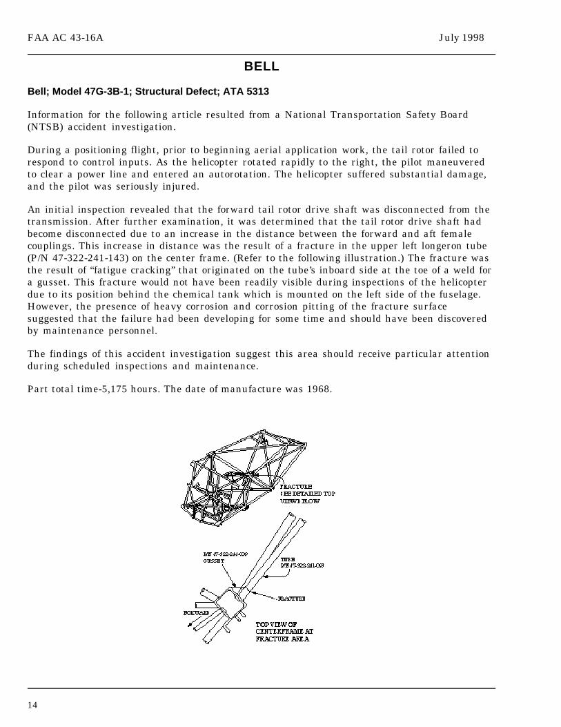
Bell; Model 47G-3B-1; Structural Defect; ATA 5313
Information for the following article resulted from a National Transportation Safety Board(NTSB) accident investigation.
During a positioning flight, prior to beginning aerial application work, the tail rotor failed torespond to control inputs. As the helicopter rotated rapidly to the right, the pilot maneuveredto clear a power line and entered an autorotation. The helicopter suffered substantial damage,and the pilot was seriously injured.
An initial inspection revealed that the forward tail rotor drive shaft was disconnected from thetransmission. After further examination, it was determined that the tail rotor drive shaft hadbecome disconnected due to an increase in the distance between the forward and aft femalecouplings. This increase in distance was the result of a fracture in the upper left longeron tube(P/N 47-322-241-143) on the center frame. (Refer to the following illustration.) The fracture wasthe result of “fatigue cracking” that originated on the tube’s inboard side at the toe of a weld fora gusset. This fracture would not have been readily visible during inspections of the helicopterdue to its position behind the chemical tank which is mounted on the left side of the fuselage.However, the presence of heavy corrosion and corrosion pitting of the fracture surfacesuggested that the failure had been developing for some time and should have been discoveredby maintenance personnel.
The findings of this accident investigation suggest this area should receive particular attentionduring scheduled inspections and maintenance.
Part total time-5,175 hours. The date of manufacture was 1968.

July 1998 FAA AC 43-16A
15
Bell; Model 407; Shutdown Procedures; ATA 6720
Bell Helicopter issued Information Letter 407-98-15, dated April 29, 1998, to allowners/operators of Model 407 helicopters. The letter was issued to advise owners/operators ofa recent incident where a tail rotor contacted the tail boom.
Two separate incidents were reported concerning contact of the tail rotor blades with the tailboom during shutdown procedures. In one report, the pilot checked the tail boom aftershutdown and found that one tail rotor blade had contacted the tail boom. The inspection of thedamaged area revealed a crease in the tail boom which was approximately 3 inches longand .25 inch deep. An additional inspection confirmed that the tail rotor yield indicators did notdisplay signs of compression.
Reportedly, some pilots use an unofficial technique of applying left pedal pressure to slow thetail rotor during shutdown. Owners/operators are cautioned to follow the procedures stated inthe Model 407 flight manual for both startup and shutdown. Specifically, owners/operators areadvised to refrain from using the technique of applying left pedal pressure to slow the rotorduring shutdown. It must be emphasized that the required flight manual procedure is to centerthe cyclic and pedals during both startup and shutdown.
The manufacturer is conducting additional testing and a detailed analysis to determine whatcaused these incidents. Owners/operators will be notified by the manufacturer when the testresults are completed.
Bell; Model 407; Slat Separation From the Helicopter; ATA 5551
During a postflight inspection, the technician discovered the left slat for the horizontalstabilizer was missing. The slat was installed on the leading edge of the stabilizer to improveairflow conditions at high angles of attack and slow speeds.
There was evidence that the slat (P/N 407-023-002-117) struck one of the tail rotor blades as itdeparted the helicopter. The pilot had not noticed any feedback in the controls during the flightthat might indicate an impact with the tail rotor had occurred.
It was determined that the four slat supports (P/N 206-023-119-109, three each, andP/N 407-023-801-127, one each) failed due to cracking in the bend radius at the horizontalstabilizer attachment points. (Refer to the following illustration.)
A fleet-wide inspection was conducted, and an additional seven helicopters were found withcracked slat supports. This inspection revealed that the supports on both the left and right slatsare cracking. The helicopter flight manual requires an inspection of the horizontal stabilizer forcondition and security.
At this time, a total of 19 slat supports have been found cracked. It was recommended thatspecial attention be given to this area during both preflight and postflight inspections topreclude the loss of the slat assembly while in flight.
Part total time average is 2,236 hours. This anomaly has not occurred on helicopters with lessthan 1,700 hours.

FAA AC 43-16A July 1998
16
McDONNELL DOUGLAS
McDonnell Douglas; Model 369D; Engine Exhaust System Defect; ATA 7810
During a scheduled inspection, the right engine exhaust stack (P/N 369A8230-504) was foundcracked.
A vibration test was accomplished and excessive vibration was detected. Further investigationrevealed the vibration was caused by loose engine mounts. The upper engine mount fastenerswere worn and did not retain the engine firmly. New “HiLock” fasteners were installed, andanother vibration test was conducted with satisfactory results.
Part total time-256 hours.
AMATEUR, EXPERIMENTAL, AND SPORT AIRCRAFT
AVIAT
Aviat (Christen); Model A-1; Husky; Aileron Cable Damage; ATA 2710
During a 100-hour inspection, a “flat spot” was noticed on the right wing aileron cable.
The “flat spot” was adjacent to the inboard fairlead on the wing strut. The area was wiped witha soft cotton cloth which revealed one broken cable strand. When the area was inspected with amagnifying glass, several other cable strands were found to be close to breaking. The samedamage was discovered on the left wing aileron cable. It appeared that the aileron cablesentered the fairlead at too great an angle. It was suggested that the manufacturer issue a kit toreplace this fairlead with a pulley.
Part total time-392 hours.
July 1998 FAA AC 43-16A
17
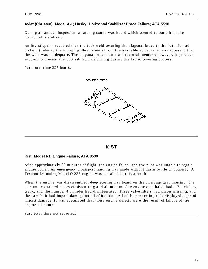
Aviat (Christen); Model A-1; Husky; Horizontal Stabilizer Brace Failure; ATA 5510
During an annual inspection, a rattling sound was heard which seemed to come from thehorizontal stabilizer.
An investigation revealed that the tack weld securing the diagonal brace to the butt rib hadbroken. (Refer to the following illustration.) From the available evidence, it was apparent thatthe weld was inadequate. The diagonal brace is not a structural member; however, it providessupport to prevent the butt rib from deforming during the fabric covering process.
Part total time-325 hours.
KIST
Kist; Model R1; Engine Failure; ATA 8530
After approximately 30 minutes of flight, the engine failed, and the pilot was unable to regainengine power. An emergency off-airport landing was made without harm to life or property. ATextron Lycoming Model O-235 engine was installed in this aircraft.
When the engine was disassembled, deep scoring was found on the oil pump gear housing. Theoil sump contained pieces of piston ring and aluminum. One engine case halve had a 2-inch longcrack, and the number 4 cylinder had disintegrated. Three valve lifters had pieces missing, andthe camshaft had impact damage on all of its lobes. All of the connecting rods displayed signs ofimpact damage. It was speculated that these engine defects were the result of failure of theengine oil pump.
Part total time not reported.

FAA AC 43-16A July 1998
18
PITTS
Pitts; Model S-2A; Magneto Failure; ATA 7414
An airshow performance was aborted due to sudden loss of a significant amount of engine oil.A landing was made without damage to the aircraft or injury to the pilot. The aircraft had aTextron Lycoming Model IO-360-A1A engine and Slick 4300 series magnetos.
An investigation revealed the magneto had loosened internally. This allowed the magneto drivegear to wobble which caused damage to the engine’s accessory drive gear.
It was stated that a similar failure occurred on a Cessna aircraft that used the same engine andmagnetos. There was no explanation of how the magneto had loosened internally.
Part total time-300 hours.
THORPE
Thorpe; Model T18; Defective Magneto; ATA 7414
During a routine inspection, the Bendix 1200 series magneto (P/N 10-349305-1) was removed toinspect the impulse coupling. It was noted that the magneto shaft was difficult to turn by handand exhibited unusual resistance.
The coils in this magneto are held in their proper location by wedges that are somewhat likehorseshoe nails. The wedge on the right had become dislodged. Further inspection revealedthat the wedge had interfered with the nylon gear. One-half of the width of the gear teeth hadbeen worn away. Since there was still a complete circle of partial teeth on the gear face, the unitcontinued to operate.
It would be wise to give this area special attention during scheduled inspections andmaintenance.
Part total time-1,250 hours and 495 hours since overhaul.
VANS
Vans; Models RV-3 and RV-3A; Wing Spar Modification; ATA 5711
Vans Aircraft Inc., has prepared and distributed Change Notice CN-2 to all known RV-3 andRV-3A owners and builders. CN-2 addresses a wing spar modification deemed necessary foraerobatic flight operations.
On Sunday, March 8, 1998, the seventh recorded RV-3 wing spar failure accident occurred whenthe right wing of the aircraft folded during an aerobatic flight demonstration. The aircraft hadnot been modified in accordance with CN-2. The accident investigation revealed that severalessential bolts were missing from the wing at the point of failure.
HISTORY: This is a “kit” aircraft which was introduced in 1973. Since its introduction, therehave been about seven in-flight structural failure accidents involving wing separation. During
July 1998 FAA AC 43-16A
19
development, the RV-3 wing strength was calculated to be 6G design and 9G design ultimate.Flight testing had been conducted to verify the 6G design strength. Of the first four in-flightwing separations, three involved structural deficiencies due to builder deviations from theconstruction plans. At that time, 1982, the manufacturer undertook the static testing of a set ofRV-3 wings. This test wing failed at a simulated 9G load, which appeared to validate its basicspar design integrity. However, because accident investigations indicated possible failure ofsecondary structures, the manufacturer issued Change Notice CN-1 to all known RV-3 ownersrecommending specific modifications be made to the rear spar attachment and root ribstructures. Similar alterations were made to the plans and to all subsequent new kits.
Some builders redesignated their aircraft as RV-3A’s when they incorporated thesemodifications. Thus, both designations appear in the FAA registry for what is basically the sameairframe.
Despite the issuance of CN-1, several more in-flight wing separation accidents occurredbetween 1984 and 1995. The manufacturer conducted another static test of an RV-3 wing, and itfailed at a load below the calculated 9G ultimate. The inconsistency between this test and the1982 test was a mystery until it was discovered that the wing tested in 1982 had used anoptional assembly technique. This optional technique simplified the construction process byallowing the individual aluminum bars, which form the spar caps, to be bonded together withepoxy. The epoxy adds nothing directly to the bending strength of the spar. Apparently, theepoxy increases the buckling resistance of the spar caps which indirectly adds to the strength ofthe wing. The end result was that the RV-3 wing spars were not as strong as calculations andprior tests had indicated.
The manufacturer conducted a series of spar modification attempts and static tests. Finally, asatisfactory spar modification was found, and CN-2 was drafted and sent to all known RV-3 andRV-3A builders and owners. One of the primary emphasis items of CN-2 was that no aerobaticflight should be conducted in any RV-3 or RV-3A aircraft until this modification wassatisfactorily performed. Along with CN-2, a wing spar modification kit was offered to allowners at no cost.
All RV-3 and RV-3A owners and builders are cautioned to limit their activities to nonaerobaticflight until compliance with CN-2 is accomplished. Builders and owners with further questionsshould contact Vans Aircraft Inc.
It is important to remember that an aircraft owner is responsible for being familiar with thelimitations of the aircraft, all current manufacturer’s modifications, service information, servicebulletins, and change notices. This information is also needed by the person performingmaintenance and/or the annual-condition inspection.
It is difficult for the manufacturer to provide this important information because manyamateur-built aircraft are no longer owned by the original builder and the ownership may betransferred from the original builder to the new owner without notification to themanufacturer. Therefore, when the manufacturer issues pertinent technical data, it is notalways possible to get that information to the current owner.
Before performing an annual-condition inspection on an amateur-built aircraft, call the kitmanufacturer and/or the Experimental Aircraft Association (EAA) to ask if there is anythingspecial you need to know during the inspection.

FAA AC 43-16A July 1998
20
POWERPLANTS AND PROPELLERS
ALLISON
Allison; Model 250C-47; Engine Temperature Anomaly; ATA 7200
The pilot reported observing a higher-than-normal measured gas temperature (MGT)indication. This engine was installed in a Bell Model 407 helicopter.
A thorough inspection of the MGT system did not reveal a cause for the anomaly. Furtherinvestigation disclosed that the outer combustion chamber (P/N 23030911) was cracked aroundthe fuel nozzle boss seam weld. The crack allowed cooling air to escape and caused the MGTtemperature to increase.
Part total time-821 hours.
PRATT & WHITNEY
Pratt & Whitney; Model PT 6A-28; Compressor Turbine Vane Security; ATA 7230
The engine power section was removed to accomplish a hot-section inspection. The techniciandiscovered that the tab washers (P/N 3001538) which are used to safety the compressor turbinevane ring and the number 2 bearing housing were not engaged with the bolt heads.
Sixteen bolts with tab washers are used for this installation. The washer tabs had not been bentover to lock the bolts in place. (Refer to the following illustration.) The engine maintenancerecords did not indicate any maintenance had taken place in this area since the last engineoverhaul. It was evident that the washer tabs had been overlooked during overhaul. Thanks tothe observant eye of the submitter, this defect was corrected before any damage occurred.
Part total time not reported.

July 1998 FAA AC 43-16A
21
AIR NOTES
AIRWORTHINESS DIRECTIVES (AD’S) ISSUED IN MAY 1998
98-10-06; Burkhart Grob G115 series which requires modifications to prevent excessive speedsor aerobatic maneuvers.
98-11-16; Dornier models 228 series which requires modifying logic in failure detection circuits.
98-11-17; Glaser-Dirks Flugzeugbau models DG-400 gliders which requires replacing Boschelectrical system regulator.
98-11-18; Glaser-Dirks Flugzeugbau model DG-400 gliders which requires replacing upperrubber shock mounts.
98-11-01; Pilatus PC-12 and PC-12/45 airplanes which requires modifications to prevent fueltank inward vent valve from freezing.
98-11-20; Pilatus PC-12 and PC-12/45 airplanes which requires modifying lavatory wall andpassenger seat configurations.
98-10-05; Raytheon (Beech) B200, B200C, and B200T airplanes which requires replacing wiringfor engine fire detector system.
98-10-12; REVO Colonial C-2, Lake LA-4 series airplanes which requires measuring forclearances.
98-10-07; Alexander Schleicher ASK21 sailplanes which requires changing flight manual’sweight-and-balance information.
98-11-14; Bell 205A-1 helicopters which requires inspecting the yoke assembly.
98-11-15; Bell 212 helicopters which requires inspecting yoke assembly.
98-10-09; Eurocopter France SA.315, SA.316, SA.319, and SA.3160 helicopters which requiresinspecting for cracks using a dye-penetrant method.
98-10-04; Eurocopter France SA-365 and SA-366 series helicopters which requires inspectionsof tail rotor blade Keviar tie-bar for cracks or delaminations.
NEW TEST FOR EXHAUST SYSTEM METAL
The following information resulted from a National Transportation Safety Board (NTSB)aircraft accident investigation.
FAA AC 43-16A July 1998
22
During the investigation, the NTSB found that the Cessna Model 421C engine exhaust systemhad failed. A review of the service difficulty reports concerning exhaust system failures onCessna 300 and 400 series revealed there were 69 reports of stainless steel exhaust systemdefects. In an attempt to distinguish between inconel and stainless steel, the NTSB used aprocedure described on page 197 of Advisory Circular (AC) 65-9A, Airframe and PowerplantMechanics General Handbook. The results of that procedure proved inconclusive. An NTSBsafety recommendation was issued, and a new procedure was developed to discern betweeninconel and stainless steel.
The new procedure is included for your information. Inconel is a nickel-chromium-iron alloyclosely resembling stainless steel in appearance. Both alloys are used interchangeably inaircraft exhaust systems. Because the two alloys look very much alike, a distinguishing test isoften necessary. Since inconel has a nickel content greater than 50 percent, one method ofidentification uses an electrochemical technique to identify the nickel content of the alloy.
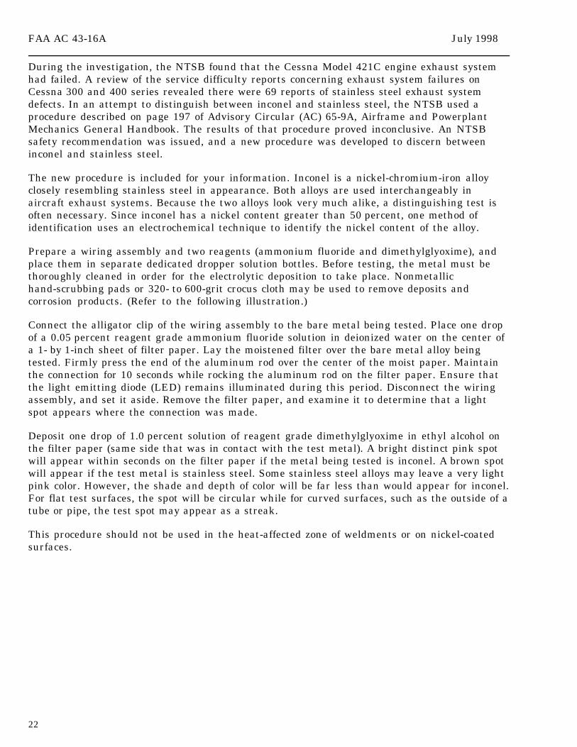
Prepare a wiring assembly and two reagents (ammonium fluoride and dimethylglyoxime), andplace them in separate dedicated dropper solution bottles. Before testing, the metal must bethoroughly cleaned in order for the electrolytic deposition to take place. Nonmetallichand-scrubbing pads or 320- to 600-grit crocus cloth may be used to remove deposits andcorrosion products. (Refer to the following illustration.)
Connect the alligator clip of the wiring assembly to the bare metal being tested. Place one dropof a 0.05 percent reagent grade ammonium fluoride solution in deionized water on the center ofa 1- by 1-inch sheet of filter paper. Lay the moistened filter over the bare metal alloy beingtested. Firmly press the end of the aluminum rod over the center of the moist paper. Maintainthe connection for 10 seconds while rocking the aluminum rod on the filter paper. Ensure thatthe light emitting diode (LED) remains illuminated during this period. Disconnect the wiringassembly, and set it aside. Remove the filter paper, and examine it to determine that a lightspot appears where the connection was made.
Deposit one drop of 1.0 percent solution of reagent grade dimethylglyoxime in ethyl alcohol onthe filter paper (same side that was in contact with the test metal). A bright distinct pink spotwill appear within seconds on the filter paper if the metal being tested is inconel. A brown spotwill appear if the test metal is stainless steel. Some stainless steel alloys may leave a very lightpink color. However, the shade and depth of color will be far less than would appear for inconel.For flat test surfaces, the spot will be circular while for curved surfaces, such as the outside of atube or pipe, the test spot may appear as a streak.
This procedure should not be used in the heat-affected zone of weldments or on nickel-coatedsurfaces.
July 1998 FAA AC 43-16A
23
AVIATION SAFETY PROGRAM MANAGER AIRWORTHINESS
The FAA has established a new position in each Flight Standards District Office (FSDO) andeach Regional office titled “Aviation Safety Program Manager (ASPM) Airworthiness (AW).” Itshould not be confused with the Operational ASPM program which has existed for a long time.
The ASPM AW in each FSDO will conduct public meetings and seminars for the benefit ofmaintenance personnel. The meetings are designed to educate, to exchange ideas, and toproduce a better understanding of why and how the FAA conducts business. An ASPM AW alsoadministers and monitors the FAA Aviation Maintenance Technician Awards Program whichwas discussed in the April 1998 edition of this publication.
We encourage you to contact your local ASPM AW for information on the benefits and seminarschedule offered by the program. The following is a list of each Regional ASPM AW. TheRegional ASPM AW’s will be able to provide the name and telephone number of the FSDOASPM AW located nearest to you.
Ralph Pack, AAL-200 Jerry Tegen, ACE-200222 W. 7th Ave., Box 14 601 E. 12th StreetAnchorage, AK 99513-7587 Kansas City, MO 64106Telephone: (907) 271-2097 Telephone: (816) 426-3526
Joe Rachiele, AEA-200 Rich Mileham, DuPage FSDOFitzgerald Federal Bldg. 111 31 W. 775 North Ave.JFK International Airport DuPage AirportJamaica, NY 11430 West Chicago, IL 60185-1058Telephone: (718) 553-3248 Telephone: (630) 443-3131
Ed Reinecker, ANE-200 Greg Young, ANM-20012 New England Executive Park 1601 Lind Ave., S.W.Burlington, MA 01803 Renton, WA 98055-4056Telephone: (617) 238-7211 Telephone: (206) 227-2254
FAA AC 43-16A July 1998
24
Phillip D. Randall, INT FSDO Fred Dryden, ASW-2008025 N. Point Blvd., Room 250 2601 Neachum Blvd.Winston-Salem, NC 27106 Fort Worth, TX 76137-4298Telephone: (910) 631-5191, X-44 Telephone: (817) 222-5285
Linda Goodrich, AWP-200P.O. Box 92007Worldway Postal CenterLos Angeles, CA 90009Telephone: (310) 215-2150, X-125
SUSPECTED UNAPPROVED PART (SUP) SEMINAR
As announced in previous editions of the Alerts, the Designee Standardization Branch,AFS-640, is once again presenting the Suspected Unapproved Part (SUP) seminar. A schedule ofthe seminars and information for requesting a SUP seminar in your area can be found below.
Seminar dates will be announced in the Alerts, the Designee Update newsletter, and on theInternet under FedWorld.gov. You may access the FedWorld BBS directly at (703) 321-3339.You may access the Alerts through the Internet, using the Regulatory Support Division,AFS-600, “HomePage” at the following address.
http://www.mmac.jccbi.gov/afs/afs600
The seminar will discuss the following:
1. Introduction to the policy of the Suspected Unapproved Part Program Office, AVR-20.2. What is an approved part/unapproved part? How can approved parts be produced?3. What is a suspected unapproved part?4. How is a suspected unapproved part reported in accordance with FAA Order 8120.10A,Suspected Unapproved Parts Program, and utilizing FAA Form 8120-11, Suspected UnapprovedParts Notification?5. How do you determine the status of parts?6. What is the procurement process?7. How do you use the Internet and FedWorld to find a list of unapproved parts?
The cost of this 8-hour seminar will be $60. The seminar may be used for the InspectionAuthorization (IA) renewal training requirement specified in Title 14 of the Code of FederalRegulations (14 CFR) part 65, section 65.93(a)(4).
The seminar is open to the aviation industry. Anyone wishing to attend may telephone(405) 954-0138. Payment is required in advance by using VISA, MasterCard, or a check.When scheduling attendance, please reference “AFS-75.”
July 1998 FAA AC 43-16A
25
SCHEDULE FORSUSPECTED UNAPPROVED PART (SUP) SEMINARS
Seminar No. 1998 Location 759806 Jul 15 Seattle, WA 759807 Jul 8 Anchorage, AK 759808 Aug 5 Ft. Lauderdale, FL 759809 Sep 16 Springfield, IL 759901 Oct 21 Rochester, NY 759902 Nov 18 Wichita, KS
An ADDITIONAL SUP seminar will be conducted in Anniston/Oxford, AL on 8/18/98. You mayregister for the seminar by calling (405) 954-0138. The additional SUP seminar is a 1-day, 8-hourseminar and can be used to meet IA renewal requirements.
If you require additional or special SUP seminars, please write to: FAA;ATTN: Mr. Elmer Hunter (AFS-640); P.O. Box 25082; Oklahoma City, OK 73125. Depending onmanpower and the availability of AFS-640 personnel, the requests for additional SUP seminarsmay be authorized. The cost for the additional SUP seminars is $60 per person. We would like aminimum of 40 attendees for a 1-day seminar and no more than 60 attendees. When the numberof attendees is greater than 70, we will conduct two 1-day seminars. The registration process isthe same as that previously discussed in this article. If you have specific questions regarding anadditional SUP seminar, please contact Mr. Elmer Hunter at (405) 954-4099.
IF YOUR ADDRESS CHANGES
If your address changes, please complete the Subscription Request Form which is located on thelast page of every edition of the Alerts. When you complete the Subscription Request Form, it isvery important that you include your full name exactly as it appears on the current label.
Also, if you are receiving more than one copy of each edition, please contact Phil Lomax at(405) 954-6487.
IF YOU WANT TO CONTACT US
If you want to contact the staff of this publication we welcome your comments, suggestions, andquestions. Also, you may use any of the following means of communication to submit reportsconcerning aviation-related occurrences.
Editor: Phil Lomax, AFS-640Telephone No.: (405) 954-6487FAX No.: (405) 954-4570 or (405) 954-4748
FAA AC 43-16A July 1998
26
Internet E-mail address: [email protected]
Mailing address: FAA ATTN: AFS-640 ALERTS P.O. Box 25082 Oklahoma City, OK 73125-5029
AFS-600 HomePage Internet address:
http://www.mmac.jccbi.gov/afs/afs600
Current and back issues of this publication may still be obtained from the FedWorld BulletinBoard System (BBS) via the Internet at the following address:
http://www.fedworld.gov/ftp.htm
Please do not hesitate to contact us.
FAA FORM 8010-4, MALFUNCTION OR DEFECT REPORT
For your convenience, FAA Form 8010-4, Malfunction or Defect Report, will be printed in everyissue of this publication.
You may complete the form, fold, staple, and return it to the address printed on the form.(No postage is required.)
SUBSCRIPTION REQUEST FORM
For your convenience, a Subscription Request Form for the Alerts, is printed in every issue.
If you wish to be placed on the distribution list, complete the form, and return it, in a stampedenvelope, to the address shown on the form.

Use this space for continuation of Block 8 (if required).

Federal Aviation AdministrationAFS-640 (Alerts)P.O. Box 25082Oklahoma City, OK 73125-5029
U.S. Departmentof Transpor tationFederal AviationAdministration
Flight Standards ServiceDesignee Standardization BranchP.O. Box 25082Oklahoma City, OK 73125-5029
Official BusinessPenalty for PrIvate Use $300
AFS-640
SUBSCRIPTION REQUEST FORMADVISORY CIRCULAR (AC) 43-16A, AVIATION MAINTENANCE ALERTS
Please use this request to subscribe to AC 43-16A or to change your address if you are presently on the mailinglist. Once your name has been entered, you will continue to receive this publication until you request your namebe removed or a copy is returned because of an incorrect address.
Because this mailing list is independent of other FAA mailing lists, it is necessary that you notify us when youraddress changes. (Our address is on the following subscription request.) If you are presently receiving thispublication it is NOT necessary to send another subscription request. The following subscription request may beduplicated, as necessary. TELEPHONE REQUESTS WILL ALSO BE ACCEPTED; THE TELEPHONENUMBER IS (405) 954-6487. THE FAX NUMBERS ARE: (405) 954-4748 and/or (405) 954-4570.
AC 43-16A SUBSCRIPTION REQUEST
If you would like to BEGIN receiving AC 43-16A, orCHANGE your address, please complete the following:
PLEASE PRINT INFORMATION LEGIBLY,INCLUDE YOUR ZIP CODE, AND THE DATEOF YOUR REQUEST.
NAME:
ADDRESS:
ZIP CODE
DATE:
CIRCLE ONE OF THE FOLLOWING:
1. This is a NEW subscription.
2. This is an ADDRESS CHANGE.
SEND ONLY ONE SUBSCRIPTION REQUEST TOTHE FOLLOWING ADDRESS:
FAA, Regulatory Support DivisionATTN: AFS-640 (Phil Lomax)P.O. Box 25082Oklahoma City, OK 73125-5029
If you require more than one copy of AC 43-16A, it may be reproduced.
U.S.Departmentof Transportation
Federal AviationAdministration
Designee Standardization BranchATTN: ALERTS, AFS-640P.O. Box 25082Oklahoma City, OK 73125-5029
AFS-640
Official BusinessPenalty for Private Use $300
BULK MAILPOSTAGE & FEES PAID
Federal AviationAdministration
PERMIT No. G44