julabo mv manual
TRANSCRIPT
19511422.doc
Refrigerated Circulators
F12F25F26F32F33F34
FP40FP45FP50
FPW50
-MV-MW
1.951.1422BE2 01/03

2
Congratulations!You have made an excellent choice.JULABO thanks you for the trust you have placed in us.This operating manual has been designed to help you gain an understanding of theprinciples of operating and possibilities of our circulators. For optimum utilizationof all functions, we recommend that you thoroughly study this manual prior tobeginning operation.
Safety WarningsTake care your unit is operated only by qualified persons.Make sure you read and understand all instructions and safety precautions listed inthis manual before installing or operating your unit. If you have any questionsconcerning the operation of your unit or the information in this manual, contactJULABO.Performance of installation, operation, or maintenance procedures other than thosedescribed in this manual may result in a hazardous situation and may void themanufacturer's warranty.Transport the unit with care. Sudden jolts or drops may cause damages in theinterior of the unit.Observe all warning labels.Never remove warning labels.Never operate damaged or leaking equipment.Never operate the unit without bath fluid in the bath.Always turn off the unit and disconnect the mains cable from the power sourcebefore performing any service or maintenance procedures, or before moving theunit.Always empty the bath before moving the unit.Never operate equipment with damaged mains power cables.Refer service and repairs to a qualified technician.
In addition to the safety warnings listed above, warnings are postedthroughout the manual. These warnings are designated by anexclamation mark inside an equilateral triangle. Read and follow theseimportant instructions. Failure to observe these instructions can resultin permanent damage to the unit, significant property damage,personal injury or death.
T MV / MW
3
TABLE OF CONTENTS
1. Operating controls and functional elements....................................................... 4
2. Quality Management System............................................................................... 6
3. Unpacking and checking...................................................................................... 6
4. Description ............................................................................................................ 6
4.1. Installation.................................................................................................. 7
4.2. Bath liquids and tubing............................................................................. 7
4.3. Filling / draining......................................................................................... 9
4.4. Temperature application to external systems......................................10
4.5. Adjusting the pump flow.........................................................................12
5. Operating procedures ........................................................................................13
5.1. Power connection...................................................................................13
5.2. Switching on / Start - Stop.....................................................................13
5.3. Setting the temperatures .......................................................................16
5.4. Warning functions ...................................................................................17
5.5. Safety installations (with shutdown function)........................................18
6. Troubleshooting guide / Error messages.........................................................19
7. Safety recommendations ...................................................................................21
8. ATC - Absolute Temperature Calibration.........................................................22
9. Electrical connections.........................................................................................23
10. Remote control .............................................................................................24
10.1. Setup for remote control ........................................................................24
10.2. Communication with a PC or a superordinated data system............25
10.3. List of commands...................................................................................26
10.4. Status messages....................................................................................26
10.5. Error messages......................................................................................27
11. Maintaining the cooling performance.........................................................28
12. Maintenance, Cleaning the unit...................................................................29
13. Technical specifications ..............................................................................30
14. EC Declaration of Conformity.....................................................................34
15. Warranty conditions .....................................................................................35
Operating controls and functional elements
4
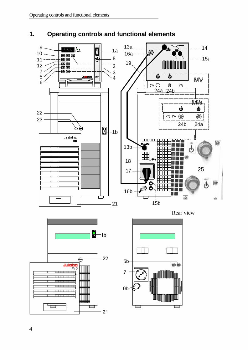
1. Operating controls and functional elements
! 1a
23
6
75 4
1b
128
9
24a 24b
2322
21
1011
13a
15a
15b
16b
17
18
16a
24b 24a
13b
14
19
Rear view
25
25
T MV / MW
5
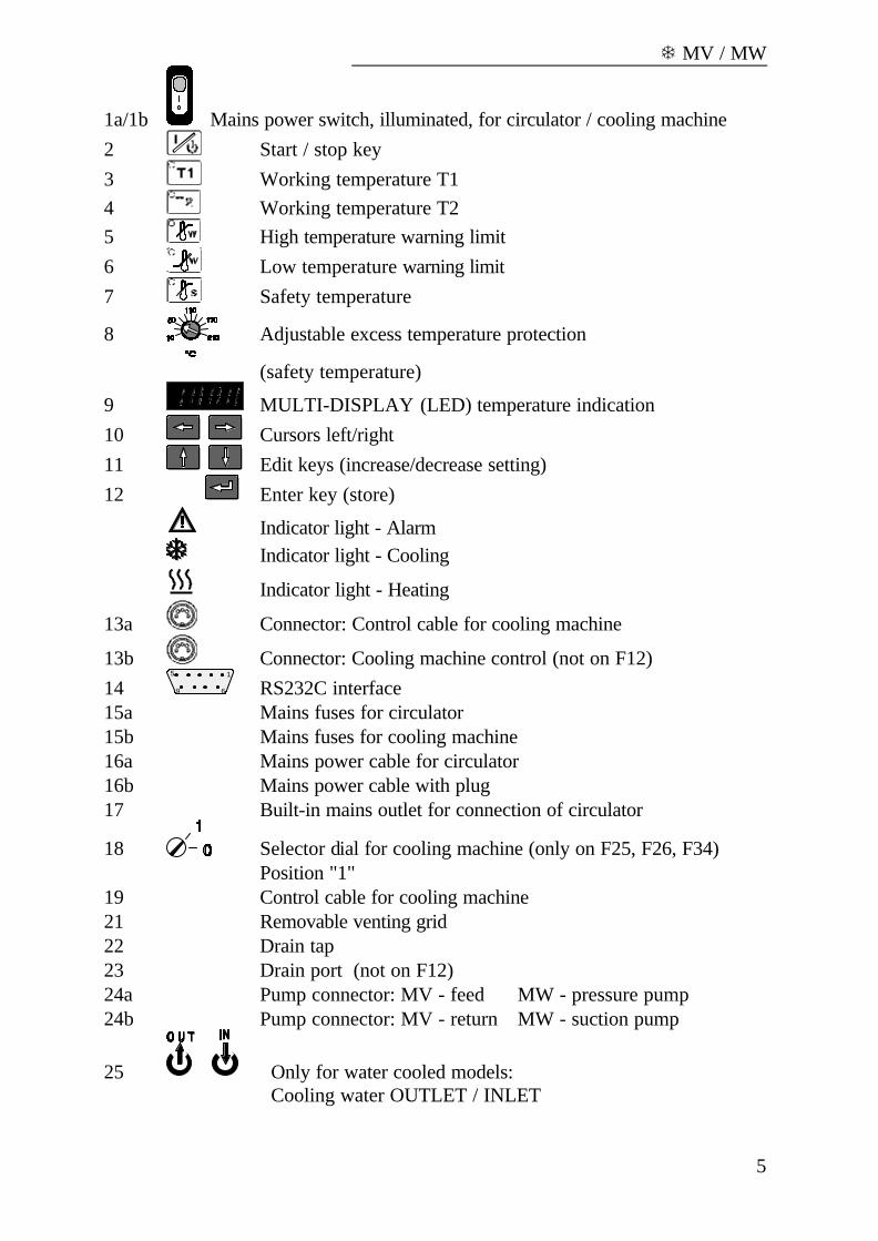
1a/1b Mains power switch, illuminated, for circulator / cooling machine2 Start / stop key3 Working temperature T14 Working temperature T25 High temperature warning limit6 Low temperature warning limit7 Safety temperature
8 Adjustable excess temperature protection
(safety temperature)
9 MULTI-DISPLAY (LED) temperature indication10 Cursors left/right11 Edit keys (increase/decrease setting)12 Enter key (store)
Indicator light - AlarmIndicator light - Cooling
Indicator light - Heating
13a Connector: Control cable for cooling machine
13b Connector: Cooling machine control (not on F12)14
15
69 RS232C interface15a Mains fuses for circulator15b Mains fuses for cooling machine16a Mains power cable for circulator16b Mains power cable with plug17 Built-in mains outlet for connection of circulator
18 Selector dial for cooling machine (only on F25, F26, F34)Position "1"
19 Control cable for cooling machine21 Removable venting grid22 Drain tap23 Drain port (not on F12)24a Pump connector: MV - feed MW - pressure pump24b Pump connector: MV - return MW - suction pump
25 Only for water cooled models:Cooling water OUTLET / INLET
Quality Management System
6
2. Quality Management System
The JULABO Quality Management System:Development, production and distribution of temperatureapplication instruments for research and industries conform to therequirements according to DIN EN ISO 9001:1994-08.
Certificate Registration No. QA 051004008.
3. Unpacking and checking
Unpack the circulator and accessories and check for damages incurred duringtransit. These should be reported to the responsible carrier, railway, or postalauthority, and a request for a damage report should be made. These instructionsmust be followed fully for us to guarantee our full support of your claim forprotecting against loss from concealed damage. The form required for filing such aclaim will be provided by the carrier.
4. Description
The JULABO refrigerated circulators employ a circulator head and a coolingmachine with bath tank, and have been designed for heating and cooling of liquidsin the bath tank.Besides the cooling aggregate, the main functional elements are the heater,circulation pump and control electronics. An electronic proportional temperaturecontrol (PID characteristic) adapts the heat supplied to the thermal requirements ofthe bath.
Setting is rapid and simple using the keypad with its easy to learn symbols. Keypadis splash-proof, easily cleaned and ergonomically designed.The microprocessor technology allows four temperature values to be stored andindicated on the MULTI-DISPLAY (LED): working temperatures T1 and T2, highand low temperature warning limits.
The safety value for excess temperature protection, a safety installationindependent from the control circuit, is adjustable on the front and visible on theMULTI-DISPLAY (LED).
The RS232C port permits modern process engineering without additional interface,directly on-line, from the circulator to your application equipment.
The circulators conform to the safety requirements specified by DIN 12 876(safety class III), as well as DIN 58 966, the guideline for first voltage rangeEN 61010.

T MV / MW
7
4.1. Preparations
4.1. Installation
• Place the unit in an upright position.
• Keep at least 20 cm of open space on the front and rear venting grids.
• Do not set up the unit in the immediate vicinity of heat sources and do notexpose to sun light.
• Before operating the unit after transport, wait about one hour after setting it up.This will allow any oil that has accumulated laterally during transport to flowback down thus ensuring maximum cooling performance of the compressor.
Only for water cooled models:Ensure circulation of cooling water by connecting thetubing to cooling water inlet (IN) and outlet (OUT) onthe rear of the recirculating cooler.Water pressure: 3.5 to 6 bar.Cooling water temperature: <20 °C
¾"
4.2. Bath liquids and tubing
Carefully read the safety data sheet of the bath liquid used,particulary with regard to the fire piont!If ethanol is used, only supervised operation is possible.
Recommended bath liquids:
Bath liquids Temperature range Flash point / fire pointThermal M +50 °C ... 170 °C >275 °C >320 °CThermal H +50 °C ... 250 °C >280 °C >350 °CThermal HY -60 °C ... 50 °C >62 °C >110 °CEthanol (C2H5OH) -100°C bis 0 °C 12 °Cdeionisiertes Wasser 5 °C bis 80 °C
ATTENTION: The maximum permissible viscosity is 30 mm2 x s-1.

Description
8
No liability for use of other bath liquids!
Order No. Bath liquid8 940 1008 940 1018 940 1028 940 1038 940 1048 940 105
Thermal MThermal MThermal HThermal HThermal HYThermal HY
10 liters container5 liters container
10 liters container5 liters container
10 liters container5 liters container
� Recommended tubing:Temperature range
CR tubingViton tubing
-20 °C to +120 °C-50 °C to +200 °C
The temperature controlling i.e. immersing of test tubes,Erlenmeyer flasks or similar objects directly within the circulatorconstitutes normal circulator practise.We do not know which substances are contained within thesevessels. Many substances are:• inflammable, easily ignited or explosive• hazardous to health• environmentally unsafei.e.:dangerous
You alone are responsible for the handling of these substances!
T MV / MW
9
4.3. Filling / draining
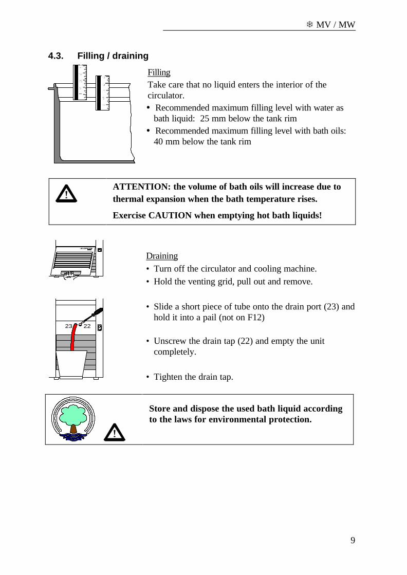
FillingTake care that no liquid enters the interior of thecirculator.� Recommended maximum filling level with water as
bath liquid: 25 mm below the tank rim� Recommended maximum filling level with bath oils:
40 mm below the tank rim
ATTENTION: the volume of bath oils will increase due tothermal expansion when the bath temperature rises.
Exercise CAUTION when emptying hot bath liquids!
Draining• Turn off the circulator and cooling machine.• Hold the venting grid, pull out and remove.
2223
• Slide a short piece of tube onto the drain port (23) andhold it into a pail (not on F12)
• Unscrew the drain tap (22) and empty the unitcompletely.
• Tighten the drain tap.
Store and dispose the used bath liquid accordingto the laws for environmental protection.
Description
10
4.4. Temperature application to external systems
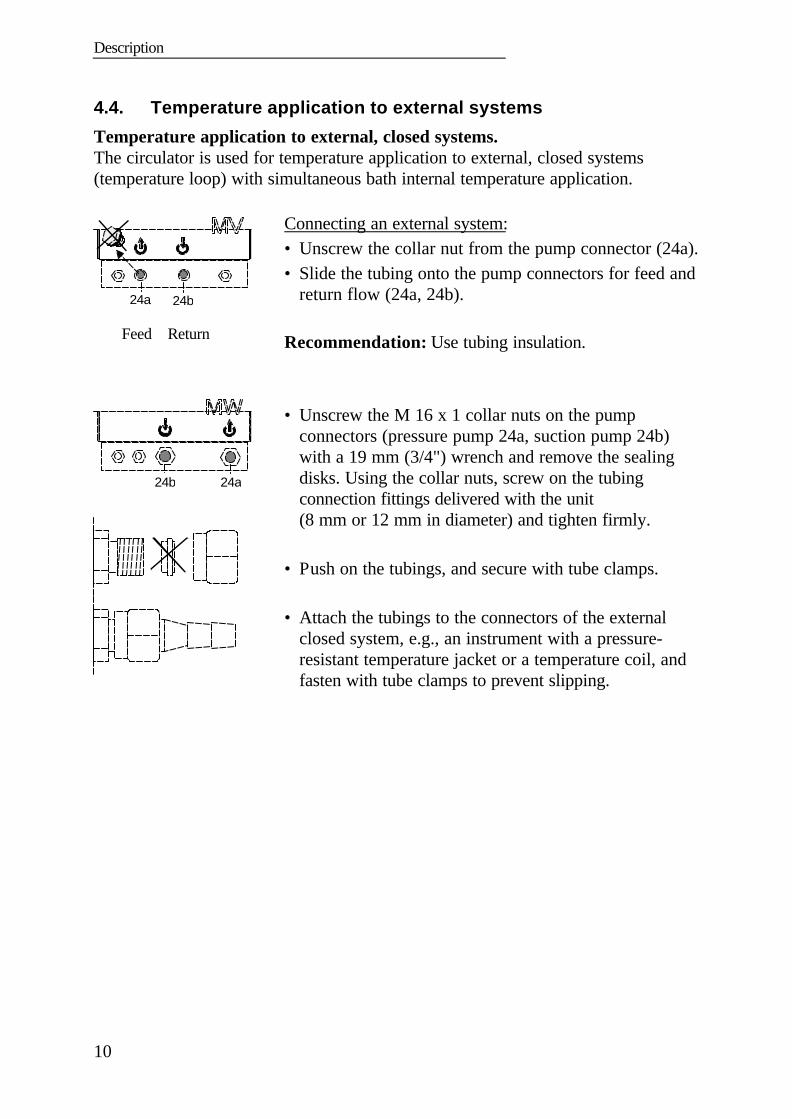
Temperature application to external, closed systems.The circulator is used for temperature application to external, closed systems(temperature loop) with simultaneous bath internal temperature application.
24a 24b
Feed Return
Connecting an external system:• Unscrew the collar nut from the pump connector (24a).• Slide the tubing onto the pump connectors for feed and
return flow (24a, 24b).
Recommendation: Use tubing insulation.
24a24b
• Unscrew the M 16 x 1 collar nuts on the pumpconnectors (pressure pump 24a, suction pump 24b)with a 19 mm (3/4") wrench and remove the sealingdisks. Using the collar nuts, screw on the tubingconnection fittings delivered with the unit(8 mm or 12 mm in diameter) and tighten firmly.
• Push on the tubings, and secure with tube clamps.
• Attach the tubings to the connectors of the externalclosed system, e.g., an instrument with a pressure-resistant temperature jacket or a temperature coil, andfasten with tube clamps to prevent slipping.
T MV / MW
11
Temperature application to external, open systems
K
S
D
H
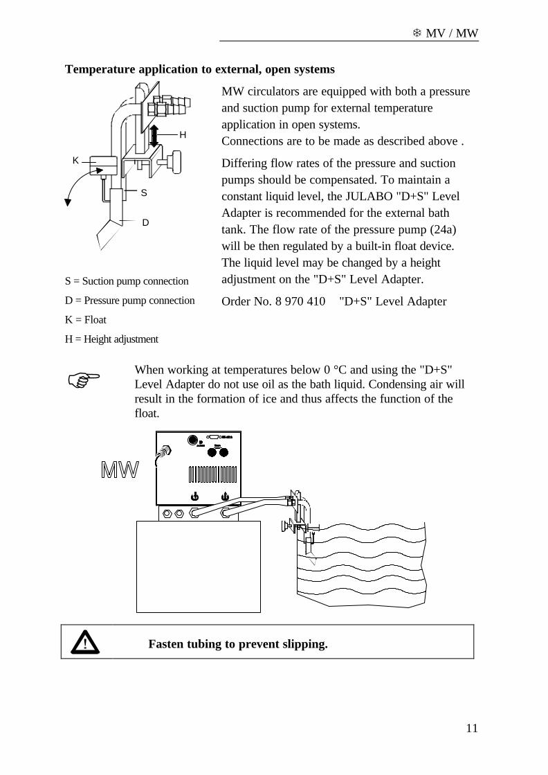
S = Suction pump connection
D = Pressure pump connection
K = Float
H = Height adjustment
MW circulators are equipped with both a pressureand suction pump for external temperatureapplication in open systems.Connections are to be made as described above .
Differing flow rates of the pressure and suctionpumps should be compensated. To maintain aconstant liquid level, the JULABO "D+S" LevelAdapter is recommended for the external bathtank. The flow rate of the pressure pump (24a)will be then regulated by a built-in float device.The liquid level may be changed by a heightadjustment on the "D+S" Level Adapter.
Order No. 8 970 410 "D+S" Level Adapter
F When working at temperatures below 0 °C and using the "D+S"Level Adapter do not use oil as the bath liquid. Condensing air willresult in the formation of ice and thus affects the function of thefloat.
Fasten tubing to prevent slipping.

Description
12
F Note: If the liquid levels in the circulator bath and the external systemare at different heights, overflowing must be prevented after thepower has been turned off. Close off both connection tubings withstandard pinchcocks or shut-off valves
Order No. Description8 970 456 Shut-off valve (suitable up to +90 °C)8 970 457 Shut-off valve (suitable up to +250 °C)
4.5. Adjusting the pump flow
1
2
The pump flow is pre-adjusted inthe factory and can be modified tosuit user requirements.
• Using a screwdriver turn the screw (1)anti-clockwise by 360 °.
• Using flat pliers turn the marking of theslide (2) to the desired position.
• Tighten the screw.
Examples:
Internal applications in the bath
A 100 % internal bath circulation(for large bath tanks)
B Reduced internal bath circulation(for smooth surface of bath liquid)
External/internal applications
C 40 % external discharge,60 % internal circulation(for large bath tanks)
D 80 % external discharge,20 % internal circulation(for small bath tanks)
T MV / MW
13
5. Operating procedures
5.1. Power connection
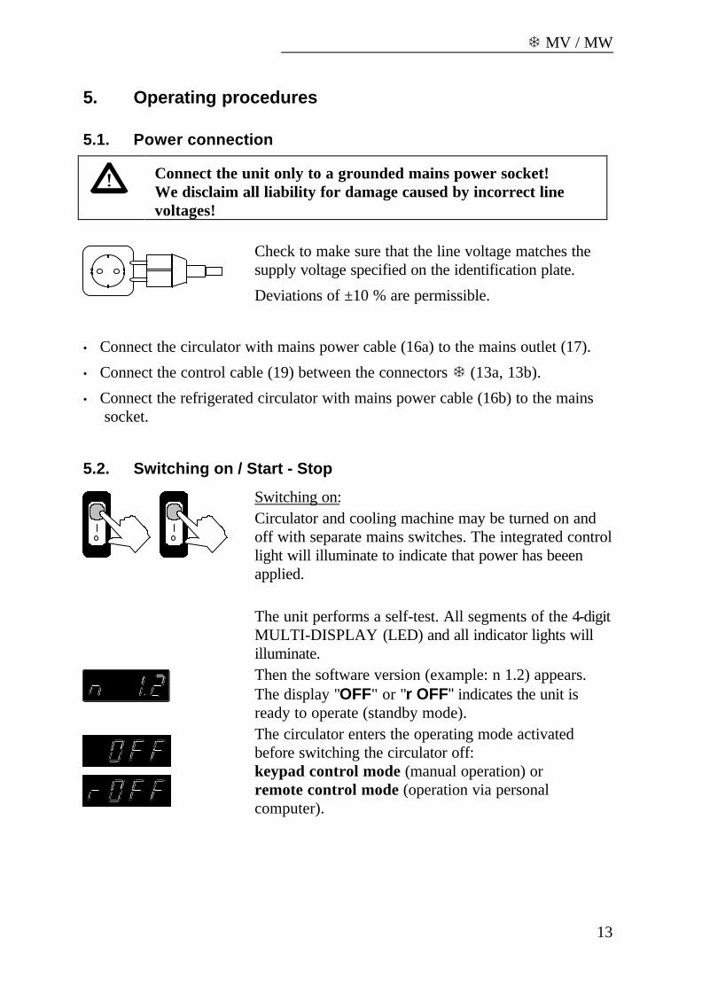
Connect the unit only to a grounded mains power socket!We disclaim all liability for damage caused by incorrect linevoltages!
Check to make sure that the line voltage matches thesupply voltage specified on the identification plate.
Deviations of ±10 % are permissible.
• Connect the circulator with mains power cable (16a) to the mains outlet (17).
• Connect the control cable (19) between the connectors T (13a, 13b).
• Connect the refrigerated circulator with mains power cable (16b) to the mainssocket.
5.2. Switching on / Start - Stop
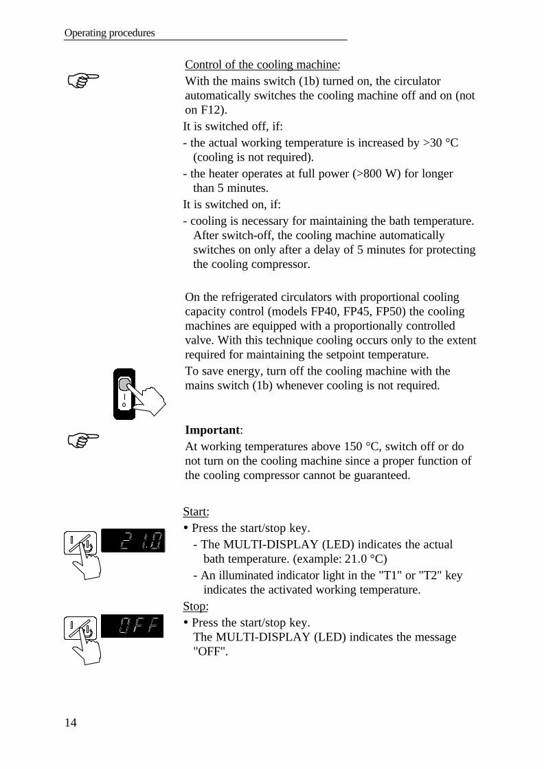
Switching on:Circulator and cooling machine may be turned on andoff with separate mains switches. The integrated controllight will illuminate to indicate that power has beeenapplied.
The unit performs a self-test. All segments of the 4-digitMULTI-DISPLAY (LED) and all indicator lights willilluminate.Then the software version (example: n 1.2) appears.The display "OFF" or "r OFF" indicates the unit isready to operate (standby mode).The circulator enters the operating mode activatedbefore switching the circulator off:keypad control mode (manual operation) orremote control mode (operation via personalcomputer).
Operating procedures
14
F
Control of the cooling machine:With the mains switch (1b) turned on, the circulatorautomatically switches the cooling machine off and on (noton F12).It is switched off, if:- the actual working temperature is increased by >30 °C
(cooling is not required).- the heater operates at full power (>800 W) for longer
than 5 minutes.It is switched on, if:- cooling is necessary for maintaining the bath temperature.
After switch-off, the cooling machine automaticallyswitches on only after a delay of 5 minutes for protectingthe cooling compressor.
On the refrigerated circulators with proportional coolingcapacity control (models FP40, FP45, FP50) the coolingmachines are equipped with a proportionally controlledvalve. With this technique cooling occurs only to the extentrequired for maintaining the setpoint temperature.To save energy, turn off the cooling machine with themains switch (1b) whenever cooling is not required.
F Important:At working temperatures above 150 °C, switch off or donot turn on the cooling machine since a proper function ofthe cooling compressor cannot be guaranteed.
Start:� Press the start/stop key.
- The MULTI-DISPLAY (LED) indicates the actualbath temperature. (example: 21.0 °C)
- An illuminated indicator light in the "T1" or "T2" keyindicates the activated working temperature.
Stop:� Press the start/stop key.
The MULTI-DISPLAY (LED) indicates the message"OFF".
T MV / MW
15
F The unit also enters the safe operating state "OFF" or "r OFF after amains power interruptance. The temperature values entered via thekeypad remain in memory. With the circulator in keypad controlmode, press the start/stop key to restart operation .With the circulator in remote control mode, the personal computermust first resend the parameters set via the interface before thecirculator may be restarted.
NOTE:The circulator has been configured and supplied by JULABO according toN.A.M.U.R. recommendations. This means for the start mode, that the unit mustenter a safe operating state after a power failure (non-automatic start mode). Thissafe operating state is indicated by „OFF“ or „rOFF“, resp. on the MULTI-DISPLAY (LED). A complete shutdown of the main functional elements such asheater and circulation pump is effected simultaneously.Should such a safety standard not be required, the AUTOSTART function(automatic start mode) may be activated, thus allowing the start of the circulatordirectly by pressing the mains power switch or using a timer.
Automatic / non-automatic start mode
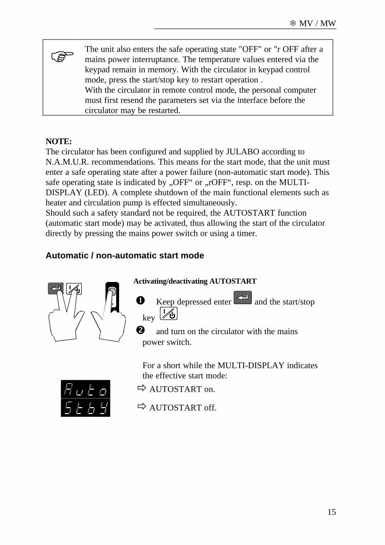
Activating/deactivating AUTOSTART
� Keep depressed enter and the start/stop
key
� and turn on the circulator with the mainspower switch.
For a short while the MULTI-DISPLAY indicatesthe effective start mode:
ð AUTOSTART on.
ð AUTOSTART off.

Operating procedures
16
Warning: For supervised or unsupervised operation with theAUTOSTART function, avoid any hazardous situation topersons or property.The circulator does no longer conform to N.A.M.U.R.recommend-ations.Take care you fully observe the safety and warning functionsof the circulator.
5.3. Setting the temperatures
Setting the working temperature "T1":
� Press the setpoint key .The indicator light blinks and the value previously setappears on the MULTI-DISPLAY (LED).
� Use the cursor keys to move left or righton the display until the numeral you wish to change isblinking.
� Use the increase/decrease arrows to changethe selected numeral (-, 0, 1, 2, 3, ... 9).
� Press enter to store the selected value (example:-15.0 °C).
The working temperature is maintained constant after ashort heat-up time (e. g. -15.0 °C).
Setting the working temperature "T2":
� Press the setpoint key .� Same procedure� as with "T1"� (example: 25.0 °C).
Selecting the working temperature:
� Press the setpoint key and then enter .
� Press the setpoint key and then enter .
T MV / MW
17
5.4. Warning functions
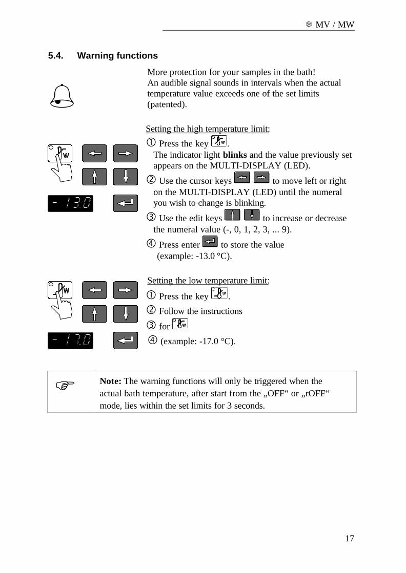
%)) )) ))More protection for your samples in the bath!An audible signal sounds in intervals when the actualtemperature value exceeds one of the set limits(patented).
Setting the high temperature limit:
� Press the key .The indicator light blinks and the value previously setappears on the MULTI-DISPLAY (LED).
� Use the cursor keys to move left or righton the MULTI-DISPLAY (LED) until the numeralyou wish to change is blinking.
� Use the edit keys to increase or decreasethe numeral value (-, 0, 1, 2, 3, ... 9).
� Press enter to store the value(example: -13.0 °C).
Setting the low temperature limit:
� Press the key .
� Follow the instructions
� for
� (example: -17.0 °C).
F Note: The warning functions will only be triggered when theactual bath temperature, after start from the „OFF“ or „rOFF“mode, lies within the set limits for 3 seconds.
Operating procedures
18
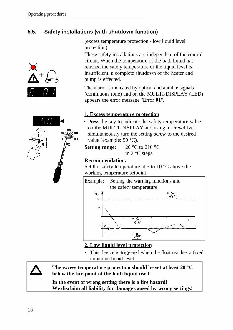
5.5. Safety installations (with shutdown function)
! +%))))
(excess temperature protection / low liquid levelprotection)These safety installations are independent of the controlcircuit. When the temperature of the bath liquid hasreached the safety temperature or the liquid level isinsufficient, a complete shutdown of the heater andpump is effected.
The alarm is indicated by optical and audible signals(continuous tone) and on the MULTI-DISPLAY (LED)appears the error message "Error 01".
1. Excess temperature protection• Press the key to indicate the safety temperature value
on the MULTI-DISPLAY and using a screwdriversimultaneously turn the setting screw to the desiredvalue (example: 50 °C).
Setting range: 20 °C to 210 °C in 2 °C steps
Recommendation:Set the safety temperature at 5 to 10 °C above theworking temperature setpoint.
Example: Setting the warning functions andthe safety temperature
-13
-15
-17
t
°C
20
50
2. Low liquid level protection• This device is triggered when the float reaches a fixed
minimum liquid level.
The excess temperature protection should be set at least 20 °Cbelow the fire point of the bath liquid used.
In the event of wrong setting there is a fire hazard!We disclaim all liability for damage caused by wrong settings!
T MV / MW
19
6. Troubleshooting guide / Error messages
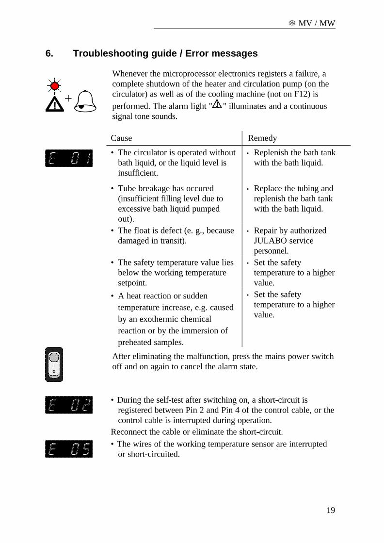
! +%Whenever the microprocessor electronics registers a failure, acomplete shutdown of the heater and circulation pump (on thecirculator) as well as of the cooling machine (not on F12) isperformed. The alarm light " " illuminates and a continuoussignal tone sounds.
Cause Remedy
• The circulator is operated withoutbath liquid, or the liquid level isinsufficient.
• Replenish the bath tankwith the bath liquid.
• Tube breakage has occured(insufficient filling level due toexcessive bath liquid pumpedout).
• Replace the tubing andreplenish the bath tankwith the bath liquid.
• The float is defect (e. g., becausedamaged in transit).
• Repair by authorizedJULABO servicepersonnel.
• The safety temperature value liesbelow the working temperaturesetpoint.
• Set the safetytemperature to a highervalue.
• A heat reaction or suddentemperature increase, e.g. causedby an exothermic chemicalreaction or by the immersion ofpreheated samples.
• Set the safetytemperature to a highervalue.
After eliminating the malfunction, press the mains power switchoff and on again to cancel the alarm state.
• During the self-test after switching on, a short-circuit isregistered between Pin 2 and Pin 4 of the control cable, or thecontrol cable is interrupted during operation.
Reconnect the cable or eliminate the short-circuit.• The wires of the working temperature sensor are interrupted
or short-circuited.
Troubleshooting guide / Error messages
20
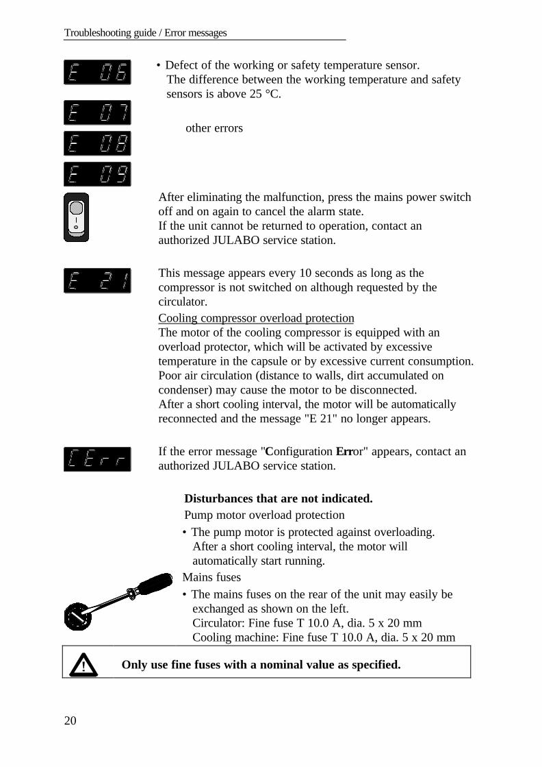
• Defect of the working or safety temperature sensor.The difference between the working temperature and safetysensors is above 25 °C.
other errors
After eliminating the malfunction, press the mains power switchoff and on again to cancel the alarm state.If the unit cannot be returned to operation, contact anauthorized JULABO service station.
This message appears every 10 seconds as long as thecompressor is not switched on although requested by thecirculator.Cooling compressor overload protectionThe motor of the cooling compressor is equipped with anoverload protector, which will be activated by excessivetemperature in the capsule or by excessive current consumption.Poor air circulation (distance to walls, dirt accumulated oncondenser) may cause the motor to be disconnected.After a short cooling interval, the motor will be automaticallyreconnected and the message "E 21" no longer appears.
If the error message "Configuration Error" appears, contact anauthorized JULABO service station.
Disturbances that are not indicated.Pump motor overload protection• The pump motor is protected against overloading.
After a short cooling interval, the motor willautomatically start running.
Mains fuses• The mains fuses on the rear of the unit may easily be
exchanged as shown on the left.Circulator: Fine fuse T 10.0 A, dia. 5 x 20 mmCooling machine: Fine fuse T 10.0 A, dia. 5 x 20 mm
Only use fine fuses with a nominal value as specified.
T MV / MW
21
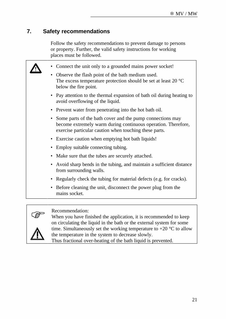
7. Safety recommendations
Follow the safety recommendations to prevent damage to personsor property. Further, the valid safety instructions for workingplaces must be followed.
• Connect the unit only to a grounded mains power socket!
• Observe the flash point of the bath medium used.The excess temperature protection should be set at least 20 °Cbelow the fire point.
• Pay attention to the thermal expansion of bath oil during heating toavoid overflowing of the liquid.
• Prevent water from penetrating into the hot bath oil.
• Some parts of the bath cover and the pump connections maybecome extremely warm during continuous operation. Therefore,exercise particular caution when touching these parts.
• Exercise caution when emptying hot bath liquids!
• Employ suitable connecting tubing.
• Make sure that the tubes are securely attached.
• Avoid sharp bends in the tubing, and maintain a sufficient distancefrom surrounding walls.
• Regularly check the tubing for material defects (e.g. for cracks).
• Before cleaning the unit, disconnect the power plug from themains socket.
F Recommendation:When you have finished the application, it is recommended to keepon circulating the liquid in the bath or the external system for sometime. Simultaneously set the working temperature to +20 °C to allowthe temperature in the system to decrease slowly.Thus fractional over-heating of the bath liquid is prevented.
ATC - Absolute Temperature Calibration
22
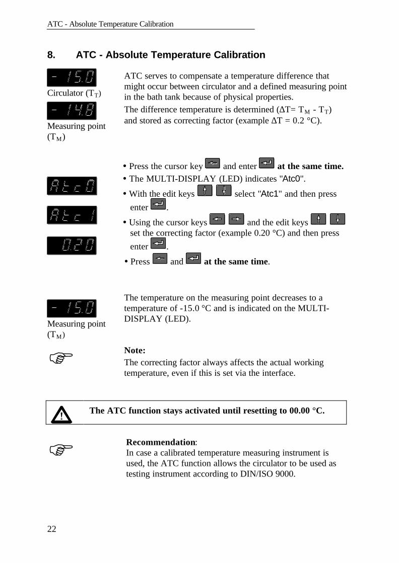
8. ATC - Absolute Temperature Calibration
Circulator (TT)
Measuring point(TM)
ATC serves to compensate a temperature difference thatmight occur between circulator and a defined measuring pointin the bath tank because of physical properties.The difference temperature is determined (∆T= TM - TT)and stored as correcting factor (example ∆T = 0.2 °C).
Measuring point(TM)
� Press the cursor key and enter at the same time.� The MULTI-DISPLAY (LED) indicates "Atc0".
� With the edit keys select "Atc1" and then pressenter .
� Using the cursor keys and the edit keys set the correcting factor (example 0.20 °C) and then pressenter .
� Press and at the same time.
The temperature on the measuring point decreases to atemperature of -15.0 °C and is indicated on the MULTI-DISPLAY (LED).
F Note:The correcting factor always affects the actual workingtemperature, even if this is set via the interface.
The ATC function stays activated until resetting to 00.00 °C.
F Recommendation:In case a calibrated temperature measuring instrument isused, the ATC function allows the circulator to be used astesting instrument according to DIN/ISO 9000.
T MV / MW
23
9. Electrical connections
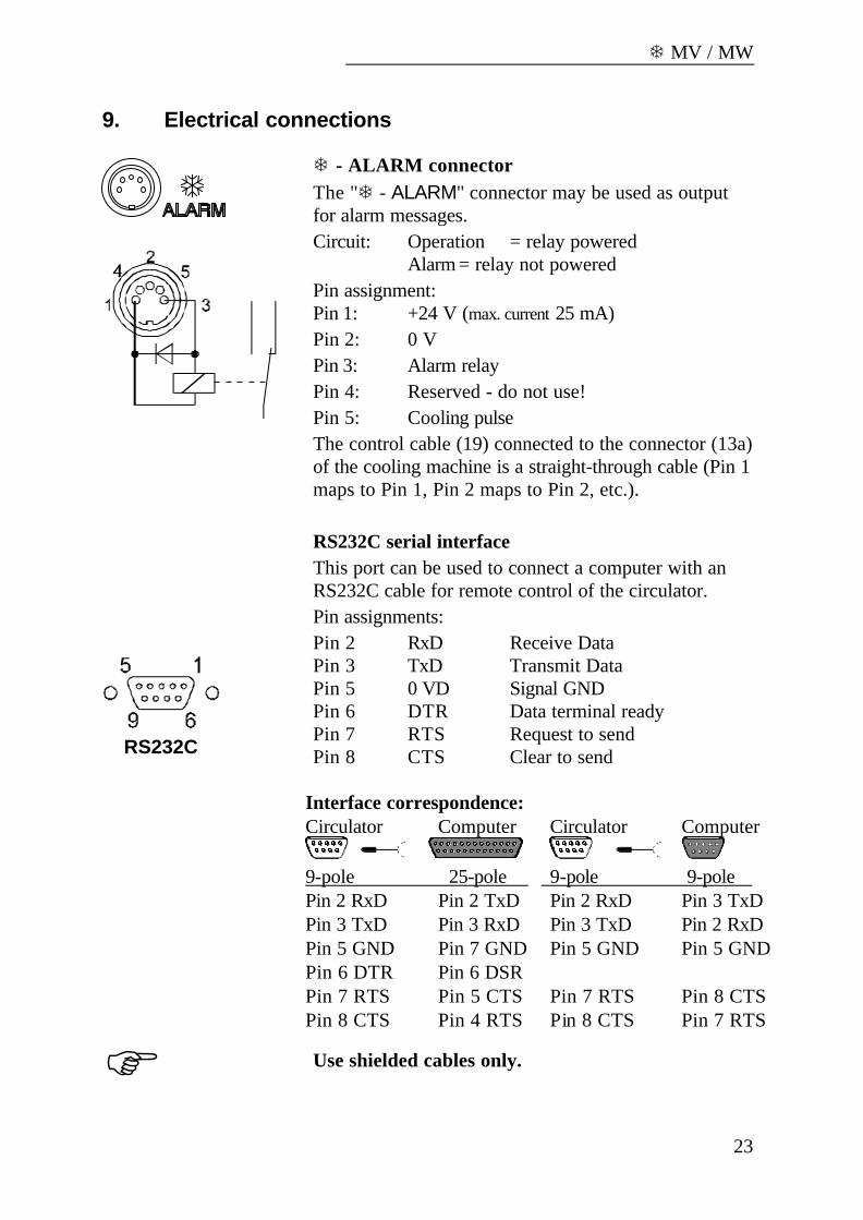
T - ALARM connectorThe "T - ALARM" connector may be used as outputfor alarm messages.Circuit: Operation = relay powered
Alarm = relay not poweredPin assignment:Pin 1: +24 V (max. current 25 mA)Pin 2: 0 VPin 3: Alarm relayPin 4: Reserved - do not use!Pin 5: Cooling pulseThe control cable (19) connected to the connector (13a)of the cooling machine is a straight-through cable (Pin 1maps to Pin 1, Pin 2 maps to Pin 2, etc.).
RS232C serial interfaceThis port can be used to connect a computer with anRS232C cable for remote control of the circulator.
RS232C
Pin assignments:Pin 2 RxD Receive DataPin 3 TxD Transmit DataPin 5 0 VD Signal GNDPin 6 DTR Data terminal readyPin 7 RTS Request to sendPin 8 CTS Clear to send
Interface correspondence:Circulator Computer Circulator Computer
9-pole 25-pole 9-pole 9-pole Pin 2 RxD ⇔ Pin 2 TxD Pin 2 RxD ⇔ Pin 3 TxDPin 3 TxD ⇔ Pin 3 RxD Pin 3 TxD ⇔ Pin 2 RxDPin 5 GND ⇔ Pin 7 GND Pin 5 GND⇔ Pin 5 GNDPin 6 DTR ⇔ Pin 6 DSR Pin 7 RTS ⇔ Pin 5 CTS Pin 7 RTS ⇔ Pin 8 CTSPin 8 CTS ⇔ Pin 4 RTS Pin 8 CTS ⇔ Pin 7 RTS
F Use shielded cables only.

Remote control
24
10. Remote control
10.1. Setup for remote control
RS232C
Interface parameters for the circulator are adjusted atconfiguration level.Enter or exit the configuration level by pressing the left arrow
and enter at the same time.
The menu item "Atc" appears on the MULTI-DISPLAY(LED). After pressing the cursor key , the second menuitem "REMOTE" is indicated. The interface parameterscannot be adjusted unless the display reads "r 0".
Adjusting interface parameters:Example: changing the baud rate.
� Using the arrow keys move the cursor to thedesired menu. The actual parameter is displayed (example:"br 24" = 2400 bauds).
� With the up and down arrows change thenumber to the desired parameter (example: 4800 bauds).The changed numerals are blinking.
� The new parameter is stored in memory by pressing enter.
Adjustable interface parametersREMOTE 0 = keypad control mode
1 = remote control mode via RS232CBAUDRATE 12 = 1200 bauds
24 = 2400 bauds48 = 4800 bauds *96 = 9600 bauds
PARITY 0 = no parity1 = odd parity2 = even parity *
HANDSHAKE0 = Protocol Xon/Xoff (software handshake)1 = Protokol RTS/CTS (hardware handshake) *
Data bits: 7; Stop bits: 1*(* Factory setting )
T MV / MW
25
F Like all parameters which can be entered through thekeypad, interface parameters are stored in memoryeven after the circulator is turned off.
10.2. Communication with a PC or a superordinated data system
Suitable terminal programs for communicating with a PC are:� MS-Windows - TERMINAL.EXE (included with MS-Windows).� MS-DOS - Procomm Plus, Datastrom Technologies.� MS-DOS - Norton Utilities.
If the circulator is put into remote control mode via theconfiguration level, the display will read "r OFF" = REMOTESTOP.The circulator is now operated via the computer.In general, the computer (master) sends commands to thecirculator (slave). The circulator sends data (including errormessages) only when the computer asks for it.
A transfer sequence consists of:• command• space (⇔; Hex: 20)• parameter (the character separating decimals in a
group is the period)• end of file (↵; Hex: 0D)
The commands are divided into in or out commands.in commands: asking for parameters to be displayedout commands: setting parameters
F The out commands are valid only in remote control mode.
Examples:• Command to set the working temperature T1 to 55.5 °C:
out_sp_00 ⇔ 55.5↵• Command to ask for the working temperature T1:
in_sp_00↵• Response from the circulator:
55.5↵
Remote control
26
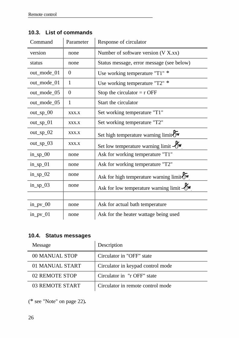
10.3. List of commands
Command Parameter Response of circulator
version none Number of software version (V X.xx)
status none Status message, error message (see below)
out_mode_01 0 Use working temperature "T1" *out_mode_01 1 Use working temperature "T2" *out_mode_05 0 Stop the circulator = r OFF
out_mode_05 1 Start the circulator
out_sp_00 xxx.x Set working temperature "T1"
out_sp_01 xxx.x Set working temperature "T2"
out_sp_02 xxx.x Set high temperature warning limitout_sp_03 xxx.x Set low temperature warning limit .
in_sp_00 none Ask for working temperature "T1"
in_sp_01 none Ask for working temperature "T2"
in_sp_02 none Ask for high temperature warning limit .
in_sp_03 none Ask for low temperature warning limit .
in_pv_00 none Ask for actual bath temperature
in_pv_01 none Ask for the heater wattage being used
10.4. Status messages
Message Description
00 MANUAL STOP Circulator in "OFF" state
01 MANUAL START Circulator in keypad control mode
02 REMOTE STOP Circulator in "r OFF" state
03 REMOTE START Circulator in remote control mode
(* see "Note" on page 22).

T MV / MW
27
10.5. Error messages
Message Description
-01 TEMP / LEVEL ALARM Safety temperature or low liquid levelalarm
-02 REFRIGERATOR ALARM Control cable disconnected
-03 EXCESS TEMPERATUREWARNING
High temperature warning " . "
-04 LOW TEMPERATUREWARNING
Low temperature warning " "
-05 TEMPERATUREMEASUREMENT ALARM
Error in measuring system
-06 SENSOR DIFFERENCEALARM
Sensor difference alarm. Workingtemperature and safety sensors reporta temperature difference of more than25 °C.
-07 I2C-BUS WRITE ERROR-07 I2C-BUS READ ERROR-07 I2C-BUS READ/WRITEERROR
Internal error
-08 INVALID COMMAND Invalid command
-10 VALUE TOO SMALL Entered value too small
-11 VALUE TOO LARGE Entered value too large
-12 WARNING : VALUE EXCEEDSTEMPERATURE LIMITS
Value lies outside the adjusted rangefor the high and low temperaturewarning limits. But value is stored.
-13 COMMAND NOT ALLOWEDIN CURRENT OPERATING MODE
Invalid command in current operatingmode
Maintaining the cooling performance
28
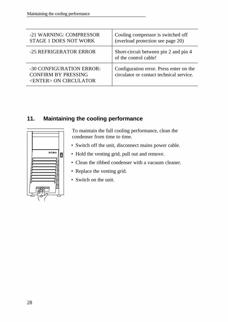
-21 WARNING: COMPRESSORSTAGE 1 DOES NOT WORK
Cooling compressor is switched off(overload protection see page 20)
-25 REFRIGERATOR ERROR Short-circuit between pin 2 and pin 4of the control cable!
-30 CONFIGURATION ERROR:CONFIRM BY PRESSING<ENTER> ON CIRCULATOR
Configuration error. Press enter on thecirculator or contact technical service.
11. Maintaining the cooling performance
To maintain the full cooling performance, clean thecondenser from time to time.
• Switch off the unit, disconnect mains power cable.
• Hold the venting grid, pull out and remove.
• Clean the ribbed condenser with a vacuum cleaner.
• Replace the venting grid.
• Switch on the unit.
T MV / MW
29
12. Maintenance, Cleaning the unit
The circulator is designed for continuous operation under normalconditions. Periodic maintenance is not required.The tank should be filled only with a bath liquid recommended byJULABO. To avoid contamination, it is essential to change thebath liquid from time to time.Clean the outside of the unit using a wet cloth and low surfacetension water.
Before cleaning the unit, disconnect the power plug from themains socket!Prevent humidity from entering into the circulator.
RepairsBefore asking for a service technician or returning a JULABOcirculator for repair, please contact an authorized JULABOservice station.
When returning a unit, take care of careful and adequate packing.JULABO is not responsible for damages that might occur frominsufficient packing.
JULABO reserves the right to carry out technical modificationswith repairs for providing improved performance of a unit.
Technical specifications
30
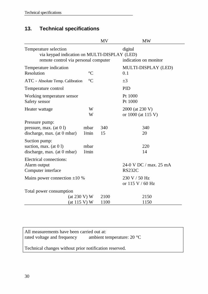
13. Technical specifications
MV MW
Temperature selection digitalvia keypad indication on MULTI-DISPLAY (LED)remote control via personal computer indication on monitor
Temperature indication MULTI-DISPLAY (LED)Resolution °C 0.1
ATC - Absolute Temp. Calibration °C ±3
Temperature control PID
Working temperature sensor Pt 1000Safety sensor Pt 1000
Heater wattage W 2000 (at 230 V)W or 1000 (at 115 V)
Pressure pump:pressure, max. (at 0 l) mbar 340 340discharge, max. (at 0 mbar) l/min 15 20
Suction pump:suction, max. (at 0 l) mbar 220discharge, max. (at 0 mbar) l/min 14
Electrical connections:Alarm output 24-0 V DC / max. 25 mAComputer interface RS232C
Mains power connection ±10 % 230 V / 50 Hz or 115 V / 60 Hz
Total power consumption(at 230 V) W 2100 2150(at 115 V) W 1100 1150
All measurements have been carried out at:rated voltage and frequency ambient temperature: 20 °C
Technical changes without prior notification reserved.
T MV / MW
31
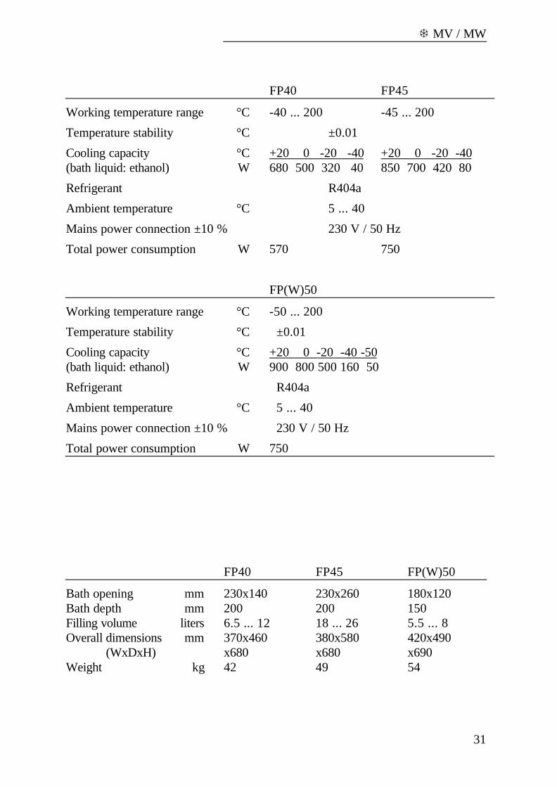
FP40 FP45
Working temperature range °C -40 ... 200 -45 ... 200
Temperature stability °C ±0.01
Cooling capacity °C +20 0 -20 -40 +20 0 -20 -40(bath liquid: ethanol) W 680 500 320 40 850 700 420 80
Refrigerant R404a
Ambient temperature °C 5 ... 40
Mains power connection ±10 % 230 V / 50 Hz
Total power consumption W 570 750
FP(W)50
Working temperature range °C -50 ... 200
Temperature stability °C ±0.01
Cooling capacity °C +20 0 -20 -40 -50(bath liquid: ethanol) W 900 800 500 160 50
Refrigerant R404a
Ambient temperature °C 5 ... 40
Mains power connection ±10 % 230 V / 50 Hz
Total power consumption W 750
FP40 FP45 FP(W)50
Bath opening mm 230x140 230x260 180x120Bath depth mm 200 200 150Filling volume liters 6.5 ... 12 18 ... 26 5.5 ... 8Overall dimensions mm 370x460 380x580 420x490
(WxDxH) x680 x680 x690Weight kg 42 49 54
Technical specifications
32
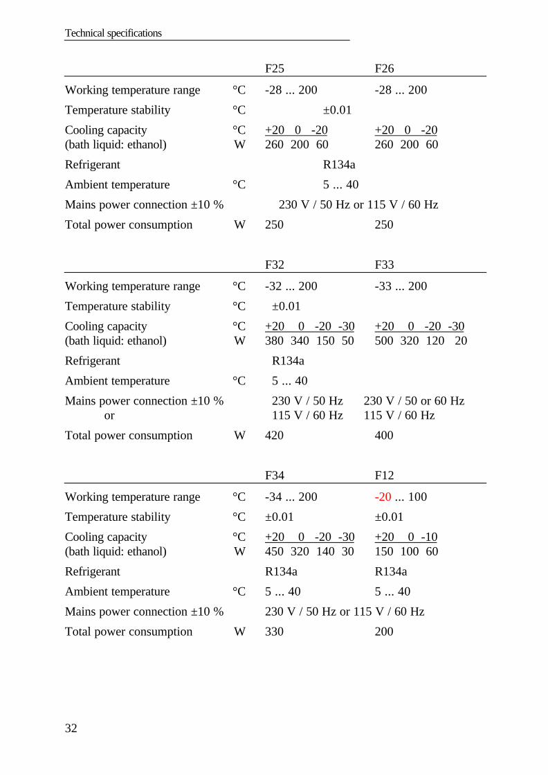
F25 F26
Working temperature range °C -28 ... 200 -28 ... 200
Temperature stability °C ±0.01
Cooling capacity °C +20 0 -20 +20 0 -20(bath liquid: ethanol) W 260 200 60 260 200 60
Refrigerant R134a
Ambient temperature °C 5 ... 40
Mains power connection ±10 % 230 V / 50 Hz or 115 V / 60 Hz
Total power consumption W 250 250
F32 F33
Working temperature range °C -32 ... 200 -33 ... 200
Temperature stability °C ±0.01
Cooling capacity °C +20 0 -20 -30 +20 0 -20 -30(bath liquid: ethanol) W 380 340 150 50 500 320 120 20
Refrigerant R134a
Ambient temperature °C 5 ... 40
Mains power connection ±10 % 230 V / 50 Hz 230 V / 50 or 60 Hzor 115 V / 60 Hz 115 V / 60 Hz
Total power consumption W 420 400
F34 F12
Working temperature range °C -34 ... 200 -20 ... 100
Temperature stability °C ±0.01 ±0.01
Cooling capacity °C +20 0 -20 -30 +20 0 -10(bath liquid: ethanol) W 450 320 140 30 150 100 60
Refrigerant R134a R134a
Ambient temperature °C 5 ... 40 5 ... 40
Mains power connection ±10 % 230 V / 50 Hz or 115 V / 60 Hz
Total power consumption W 330 200
T MV / MW
33
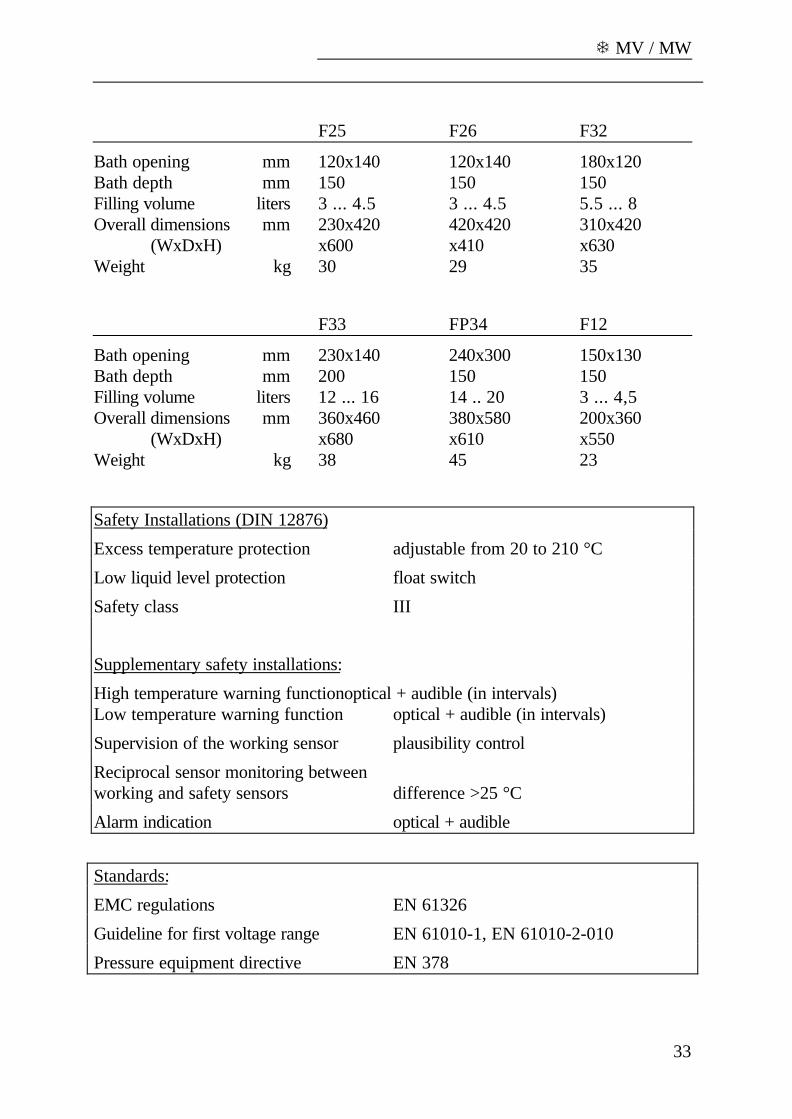
F25 F26 F32
Bath opening mm 120x140 120x140 180x120Bath depth mm 150 150 150Filling volume liters 3 ... 4.5 3 ... 4.5 5.5 ... 8Overall dimensions mm 230x420 420x420 310x420
(WxDxH) x600 x410 x630Weight kg 30 29 35
F33 FP34 F12
Bath opening mm 230x140 240x300 150x130Bath depth mm 200 150 150Filling volume liters 12 ... 16 14 .. 20 3 ... 4,5Overall dimensions mm 360x460 380x580 200x360
(WxDxH) x680 x610 x550Weight kg 38 45 23
Safety Installations (DIN 12876)
Excess temperature protection adjustable from 20 to 210 °C
Low liquid level protection float switch
Safety class III
Supplementary safety installations:
High temperature warning functionoptical + audible (in intervals)Low temperature warning function optical + audible (in intervals)
Supervision of the working sensor plausibility control
Reciprocal sensor monitoring betweenworking and safety sensors difference >25 °C
Alarm indication optical + audible
Standards:
EMC regulations EN 61326
Guideline for first voltage range EN 61010-1, EN 61010-2-010
Pressure equipment directive EN 378

EC Declaration of Conformity
34
14. EC Declaration of Conformity
The following unit complies with the essential safety requirements outlined by theEC Directives concerning the guidelines for electromagnetic compatibility(89/336/EEC), low voltage regulations (73/23/EEC) and the pressure equipmentdirective (97/23/EEC).
Refrigerated Circulator:Circulator: MV, MWRefrigerated bath: F12, F25, F26, F32, F33, F34
FP40, FP45, FP50, FPW50
This unit is manufactured in compliance with the following guidelines
electrical equipment for control technology and laboratory application –EMC requirements outlined by
EN 61326
safety regulation for electrical devices for measuring, control andlaboratory application specified by
EN 61010
refrigerated and heating circulators – safety and environmental – consciousrequirements outlined by
EN 378
Julabo Labortechnik GmbHEisenbahnstr. 45D-77960 Seelbach / Germany G. Juchheim, Managing
Director
T MV / MW
35
15. Warranty conditions
JULABO Labortechnik GmbH warrants its products against defects in material orin workmanship, when used under appropriate conditions and in accordance withappropriate operating instructions for a period of no less than
ONE YEAR
Extension of the warranty period – free of charge
With the ‘1PLUS warranty’ the user receives a free of charge extension to thewarranty of up to 24 months or 10.000 working hours; which ever is achievedfirst.
To apply for this extended warranty the user must register the unit on the Julaboweb site www.julabo.de, indicating the serial no. The extended warranty will applyfrom the date of Julabo Labortechnik GmbH’s original invoice.
Julabo Labortechnik GmbH reserves the right to decide the validity of anywarranty claim. In case of faults arising either due to faulty materials orworkmanship, parts will be repaired or replaced free of charge, or a newreplacement unit will be supplied.
Any other compensation claims are excluded from this guarantee.