jsc-10589 section 1 - · pdf filejsc-10589 section 1 introduction 1.1 purpose the purpose of...
TRANSCRIPT
JSC-10589
SECTION 1INTRODUCTION
1.1 PURPOSE
The purpose of the document is to conceptualize the rendezvous (RNDZ)mission phase and to define the techniques and procedures required toperform the Orbiter/target vehicle RNDZ and proximity operations (PROX OPS)The use of this document is to serve as a source of procedures and flighttechniques information for flight data file (PDF) development, and toprovide rationale and background for all RNDZ operators (flight crew,Mission Control Center (MCC), mission design, payload reps, etc.)*
This book represents an attempt to distill and organize the accumulatedwisdom of the RNDZ procedures group, the rendezvous analysis groups innavigation (NAV), systems, guidance, flight dynamics, pointing, and otherspecialists, along with the experience accumulated by flight crews in the1983-1985 period.
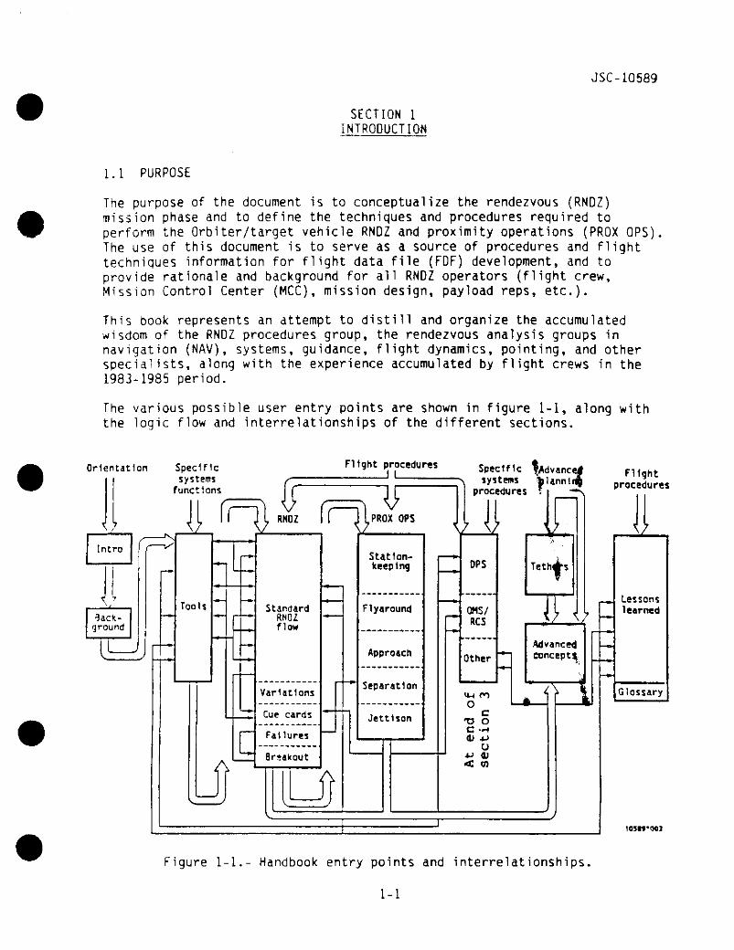
The various possible user entry points are shown in figure 1-1, alongthe logic flow and interrelationships of the different sections.
with
Orientation Specificsystems
functions
Flight proceduresJ I Specific ^Advance*
systems fclannlrjprocedures * -*•*
Flightprocedures
Cue cards
Failures
8r;akout
10319*00}
Figure 1-1.- Handbook entry points and interrelationships
1-1

JSC-10589
1.2 APPROACH
This handbook consists of sections on background principles, on tools andtechniques, on actual procedures and rationale, and on considerationsrelevant to future RNDZ missions. Depending on the needs and background ofthe user, it can be entered at several points. It can serve as asummary/review, as a reference, as a menu of existing procedures, as a guidefor defining novel procedures; above all, it is meant to be useful to thespaceflight operations community as a whole.
1.3 STS-UNIQUE FEATURES
Significant changes in vehicle systems and RNOZ mission design have occurredsince the RNOZ missions during Gemini, Apollo, and SkyTab (1965-1975).These changes required a deliberate and careful reappraisal of all phases oforbital RNDZ as the Space Transportation System (STS) accomplishes it. Someof these changes are:
A. Targets (TGT's) no longer have transponders, which used to allow rangingat 300 n. mi. The passive "skin track" radar mode only acquires at arange of 10 to 15 n. mi. No target-mounted transponders are currentlymanifested.
B. The variety of potential RNOZ TGT's and mission scenarios has greatlyexpanded. For example, the STS is the first NASA program capable ofrendezvous with debris.
C. Optical sighting techniques have changed. Rather than direct crewsighting through a wide-angle optical system, an automatic star tracker(ST) is provided - but this requires accurate Orbiter pointing to work.Manual pointing is possible through the crewman optical alignment sight(COAS).
0. The arrangement of the Orbiter reaction control system (RCS) thrusterswas dictated by aerodynamic concerns (Apollo command service module(CSM) RCS quads were aligned purely on a geometric basis) which resultsin significant axis cross-coupling and unwanted translation effects fromattitude maneuvers (MNVR's) (the verniers are worse offenders than theprimaries). This impacts accuracy of state vector (SV) propagation andof crew control during PROX OPS.
E. The ground tracking coverage has changed. There is going to be voiceand telemetry (TM) contact throughout most of the orbit via the Trackingand Data Relay Satellite System (TDRSS). Tracking coverage for groundnavigation is a mixture of three different systems: the S-band Dopplersites of the Ground Spacecraft Tracking and Data Network (GSTON), the C-band skin-track sites of the Department of Defense (DoD), and Trackingand Data Relay Satellite (TORS). For secure missions, the GSTDN isreplaced by the DoD's Remote Tracking Station (RTS) S-band sites.
1-2
JSC- 10589
F. Although redundancy exists in Orbiter systems such as data processingsystem (DPS), inertial measurement units (IMU's), etc., many RNOZ NAVsensors are single string.
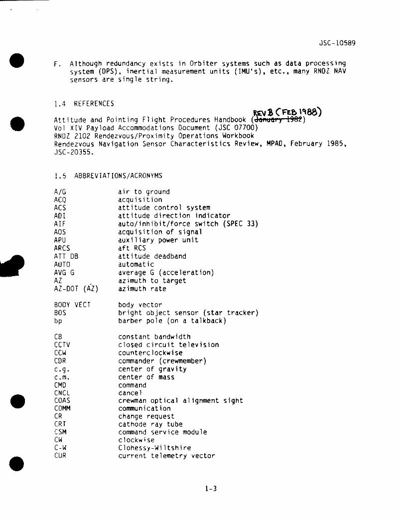
1.4 REFERENCES
Attitude and Pointing Flight Procedures Handbook (damjai'j 1002)Vol XIV Payload Accommodations Document (JSC 07700)RNDZ 2102 Rendezvous/Proximity Operations WorkbookRendezvous Navigation Sensor Characteristics Review, MPAD, February 1985,JSC-20355.
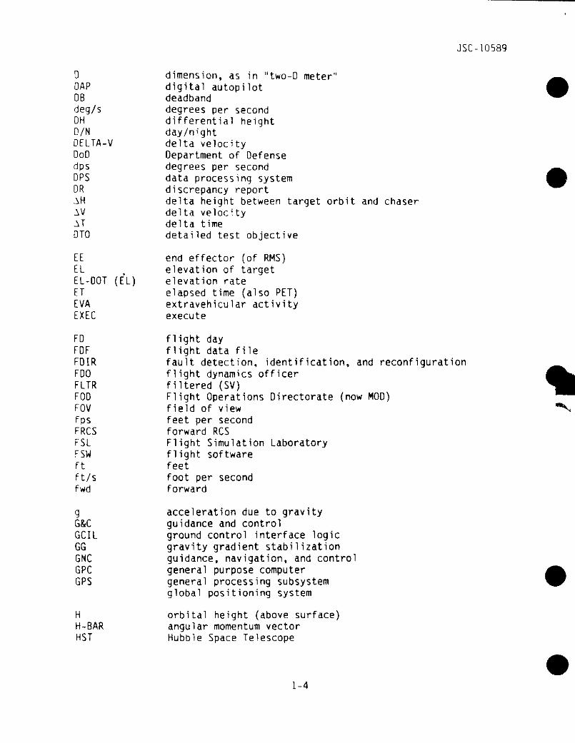
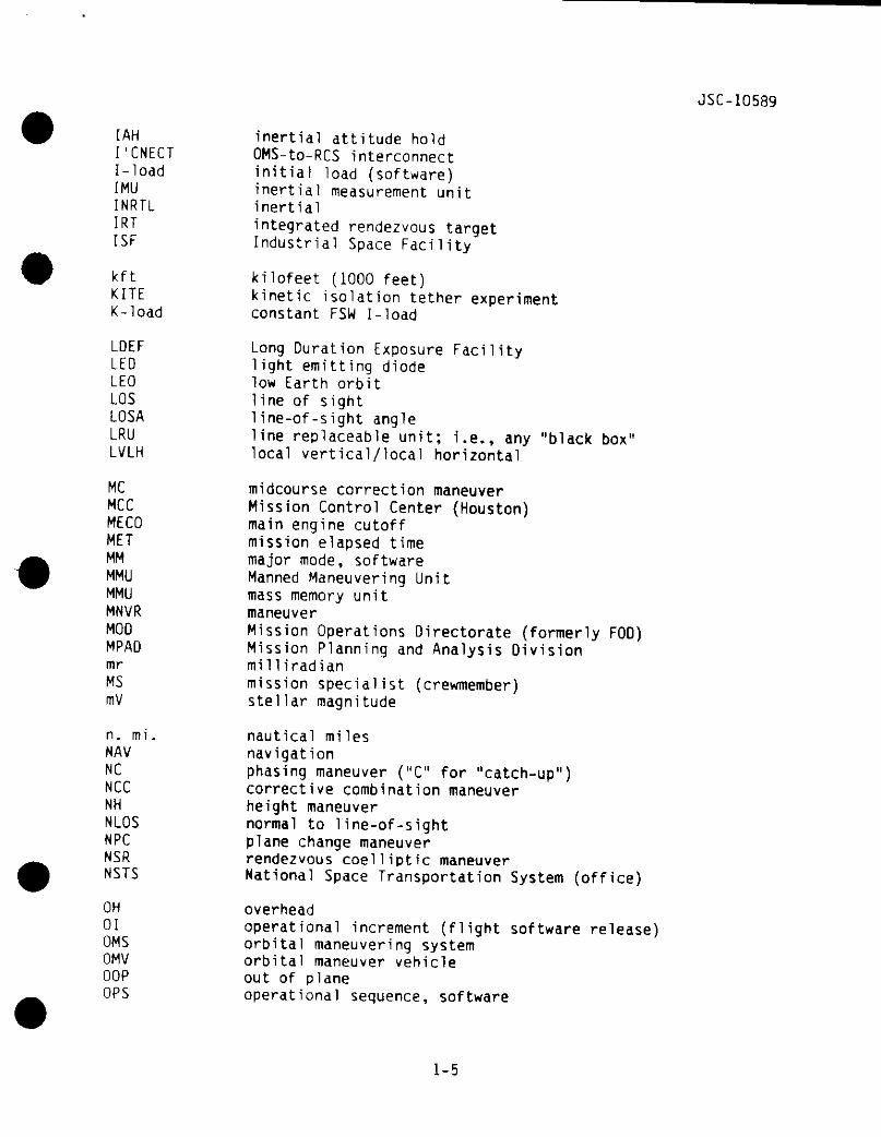
1.5 ABBREVIATIONS/ACRONYMS
A/G air to groundACQ acquisitionACS attitude control systemADI attitude direction indicatorAIF auto/inhibit/force switch (SPEC 33)AOS acquisition of signalAPU auxiliary power unitARCS aft RCSATT DB attitude deadbandAUTO automaticAVG G average G (acceleration)AZ t azimuth to targetAZ-DOT (AZ) azimuth rate
BODY VECT body vectorBOS bright object sensor (star tracker)bp barber pole (on a talkback)
CB constant bandwidthCCTV closed circuit televisionCCW counterclockwiseCDR commander (crewmember)e.g. center of gravityc.m. center of massCMO commandCNCL cancelCOAS crewman optical alignment sightCOMM communicationCR change requestCRT cathode ray tubeCSM command service moduleCW clockwiseC-W Clohessy-WiItshireCUR current telemetry vector
1-3
JSC-10589
0 dimension, as in "two-D meter"DAP digital autopilotDB deadbanddeg/s degrees per secondOH differential heightD/N day/nightDELTA-V delta velocityDoD Department of Defensedps degrees per secondDPS data processing systemDR discrepancy reportAH delta height between target orbit and chaserAV delta velocityAT delta timeDTO detailed test objective
EE end effector (of RMS)EL t elevation of targetEL-OOT (EL) elevation rateET elapsed time (also PET)EVA extravehicular activityEXEC execute
FD flight dayPDF flight data fileFDIR fault detection, identification, and reconfigurationFDO flight dynamics officerFLTR filtered (SV)FDD Flight Operations Directorate (now MOD)FOV field of view "*fps feet per secondFRCS forward RCSFSL Flight Simulation LaboratoryFSW flight softwareft feetft/s foot per secondfwd forward
g acceleration due to gravityG&C guidance and controlGCIL ground control interface logicGG gravity gradient stabilizationGNC guidance, navigation, and controlGPC general purpose computerGPS general processing subsystem
global positioning system
H orbital height (above surface)H-BAR angular momentum vectorHST Hubble Space Telescope
1-4
JSC-10589
I'CNECTI-loadIMUINRTLIRTISF
kftKITEK-load
LDEFLEDLEOLOSLOSALRULvlH
MCMCCMECOMETMMMMUMMUMNVRMOOMPADmrMSmV
n, mi.NAVNCNCCNHNLOSNPCNSRNSTS
OH01QMSOMVOOPOPS
inertial attitude holdOMS-to-RCS interconnectinitial load (software)inertial measurement unitinertialintegrated rendezvous targetIndustrial Space Facility
kilofeet (1000 feet)kinetic isolation tether experimentconstant FSW I-load
Long Duration Exposure Facilitylight emitting diodelow Earth orbitline of sightllne-of-sight angleline replaceable unit; i.e., any "black box"local vertical/local horizontal
midcourse correction maneuverMission Control Center (Houston)main engine cutoffmission elapsed timemajor mode, softwareManned Maneuvering Unitmass memory unitmaneuverMission Operations Directorate (formerly FOD)Mission Planning and Analysis Divisionmilliradianmission specialist (crewmember)stellar magnitude
nautical milesnavigationphasing maneuver ("C" for "catch-up")corrective combination maneuverheight maneuvernormal to 1ine-of-sightplane change maneuverrendezvous coelliptic maneuverNational Space Transportation System (office)
overheadoperational increment (flight software release)orbital maneuvering systemorbital maneuver vehicleout of planeoperational sequence, software
1-5
JSC-10589
OPS-0 idle modeORB orbitalOTV orbital transfer vehicle
PAD preliminary advisory dataRAM Payload Assist Modulepb pushbuttonPOP Plasma Diagnostic PackagePDRS payload deployment and retrieval systemPET phase elapsed timePI plume impingementPIR problem incident report (now called OR)PL payloadPLB payload bayPLBD payload bay doorsPIT pilot (crewmember)PMG plasma motor generatorPNL panelPOCC Payload Operations Control CenterPOP perpendicular to orbital planePRCS primary RCSPREL preliminaryPROX OPS proximity operations phasePS payload specialistPTC passive thermal control
R _ range to targetR-BAR (R) radius vector axisR-DOT (ft) range rate to target, (+) opening, (-) closingRCS radar cross sectionRCS reaction control systemRED radar enhancement deviceREL relativeREL release (flight software)REV revolution about Earth, usually about 90 minutes in LEOrf radio frequencyRFPHB Rendezvous Flight Procedures HandbookRHC rotational hand controllerRM redundancy managementRMS Remote Manipulator SystemRNDZ rendezvousROT rotationrpm revolutions per minuteRPY roll -pitch-yawRR rendezvous radarRSS "root of sum of squares"
sec secondsSEDS small expendable deployment systemSEP separationSES Shuttle Engineering SimulatorSK stationkeeping
1-6
JSC-10589
SMSMMSMRMSMSSORSPARTAN
SPASSPECSQRTSRSRMSS
STDNSTRKSTSSUMSVSYS
ttbTBDTBSTORSTMTFTGTTHCTHETA (B)TITiTIGTPSTRKTSTSSTSS-0TSS-STVCTVRTWT
UNIV PTGUPUPP
V-BAR (V)VELVERN
systems managementSolar Maximum Mission SatelliteSolar Max rescue mission (STS 41-C)Shuttle mission simulatorstable orbit rendezvousShuttle Pointed Autonomous Research Tool for Astronomony(a retrievable free-flier)Shuttle pallet satellitespecialist display, flight softwaresquare rootsunrisesolid rocket motorsunsetSpace StationSpaceflight Tracking and Data NetworkStar trackers (preferred)Space Transportation Systemsummarystate vectorsystem
timetalkbackto be determinedto be suppliedTracking and Data Relay Satellitetelemetryterminal phase finaltargettranslation hand controllerelevation angle of target from Orbiter (local horizontal)transition initiate maneuver (former acronym for Ti)transition initiate maneuvertime of ignitionThermal Protection Systemtrackingtarget suppress (feature of star tracker)tethered satellite systemTSS deployer mechanismTSS satellitethrust vector controlthrust vector rolltraveling wave tube (in K-band RR)
universal pointinguniversal pointinguser parameter processing (in GPC's)
velocityvelocity vector axisvelocityvernier
1-7
JSC-10589
VGO velocity to goVRCS vernier RCSVV velocity vector
X cross, as in "X-hair"XLV X local vertical
Y Orbiter/target out-of-plane distance (kft)Y-OOT Orbiter/target out-of-plane rate (fps)YLV Y local vertical
ZLV Z local vertical
1-8
JSC-10589
SECTION 2BACKGROUND INFORMATION
2.1 DEFINITION
A RNDZ, simply stated, is accomplished when two spacecraft, each in its ownorbit, are brought together by a series of systematic and separate MNVR'sdesigned to achieve a gentle meeting at a particular point in an orbit.
One of the two spacecraft is termed the target vehicle and is usually aboveand ahead of the second spacecraft, which is normally called the chaser.Traditionally the TGT vehicle has been launched first into an unchangingorbit; then, RNDZ MNVR's are performed by the chaser vehicle. The launchwindows for the chaser vehicle are normally established so the orbitalinsertion of the chaser is in the plane of the TGT vehicle, with allowancefor differential nodal regression due to initial altitude differences. Oncethe orbits are coplanar, that is, having a wedge angle between them of 0°,the RNDZ problem becomes two dimensional (altitude and downrange).
After orbit insertion, an orbit adjustment is made to affect the in-planephase angle between the two vehicles. The RNDZ profile is designed toaccommodate a wide range of phase angles at the in-plane launch point. Fromorbital mechanics it is known that the angular rate of the chaser vehicle,which is launched into a lower orbit, is greater than that of the higherorbiting TGT vehicle. Thus, the chaser will begin to catch up and the phaseangle w i l l decrease. The exact catch-up rate depends on the size of therelative orbits.
The chaser vehicle executes orbit shaping MNVR's, based on NAV data fromground sensors and from a succession of on-board sensors. The final MNVRsegment of this sequence causes the trajectory of the chaser vehicle tointercept the trajectory of the TGT vehicle. Several small MNVR's areusually planned after this intercept MNVR to assure the chaser remains on anintercept trajectory.
Once close to the TGT vehicle a series of braking MNVR's are performed toprevent the chaser vehicle from flying by, or into, the TGT. Depending onthe type of TGT, these MNVR's may be done in close or out at some greaterrange. Following the braking MNVR's, a stable condition relative to the TGTvehicle (known as stationkeeping) is achieved. At this point, the RNOZphase is concluded and any further adjustments to the relative positions ofthe two vehicles fall under the title PROX OPS phase.
PROX OPS can be defined intuitively as the operation of one orbitingspacecraft in the vicinity of another. In more practical terms, it can bedefined as a mission phase during which various dynamic trajectory manage-ment tasks are conducted manually by one of two coordinating satelliteswhile in the near vicinity of the other. More specifically the relativeposition and rates are sufficiently stabilized and small (usually
2-1
JSC- 10589
< 0.5 n. mi. and 1 ft/s) so as to preclude the requirement for rendezvous(with all attendant navigation, targeting, and MNVR execution) in order torestore proximity.
PROX OPS includes the traditional functions of statlonkeeping, transition(flyaround), approach, and separation. But new functions have been added,ranging from inspection, grappling, or Manned Maneuvering Unit (MMU) opera-tions and retrieval, to various novel medium- and long-range stationkeepingtechniques required by STS payloads. Additionally, concerns related tohardware (such as sensor performance, or RCS jet plume impingement),software, and crew procedures are much more important with the STS thanpreviously with Apollo.
This section has presented a simplified explanation. The task of RNOZ andstationkeeping with another orbiting vehicle can become quite complicated.For this reason a standardized set of systematic MNVR's is designed toaccomplish the following:
• Maximize the probability of success.
• Achieve the RNDZ at a particular point in the orbit (dictated primarilyby lighting conditions) with a single fixed crew timeline, generated ayear before the flight.
• Accommodate all potential phasing conditions and requirements
• Optimize the use of crew time in orbit
• Minimize the amount of propellant used
• Optimize the use of onboard NAV sensor capabilities
These tasks break down intovfiyflJbasic components, each of which is to beaddressed in detail in this handbook. They are:
• Vehicle control
• NAV
• Targeting
• MNVR guidance
• Terminal phase manual trajectory control (including braking operations)
• PROX OPS
Different techniques are used to "control" the Orbiter trajectory duringRNDZ and PROX OPS. RNDZ operations utilize closed loop guidance, navi-gation, and control to achieve a desired relative state. PROX OPS utilizecrew visual observations and piloting techniques (along with univer^rLipointing (UP) attitude control) to achieve a desired relative state.
2-2
JSC-10589
Navigation starts with ground tracking of both vehicles. When the relativerange decreases to several hundred miles, onboard relative NAV can be used.Relative NAV involves the manner in which the various tracking sensors(radar, STRK, and COAS) are operated with the goal of improving the accuracyof the onboard relative state. After sufficient NAV data have been proces-sed, the crew targets the required velocity correction for tbe-suMeqtientRNDZ MNVR. This involves computation of a solution using the targetingequations. After maneuvering to the burn attitude and making the othernecessary preparations, the crew initiates the MNVR at time of ignition(TIG). RCS burns are executed manually with the translational handcontroller (THC). However, orbital maneuvering system (QMS) burn executionis more automatic and only requires the crew to monitor the system andguidance parameters on the cathode ray tube (CRT) display (and push theexecute key prior to TIG). Upon MNVR completion, the cycle repeats itselfwith additional relative NAV. After the final post-Ti midcourse MNVR, thecrew can manually achieve stationkeeping by:
• Translating normal to the line of sight (LOS) to maintain an intercepttrajectory
• Translating (braking) along the LOS to achieve a velocity match
Other tasks which are not unique to RNDZ operations, but are performedduring this phase, should be noted. These include:
• Ground-targeted QMS burns
• IMU alignments
• Systems management
• Orbiter/MCC communications interface
Therefore, to ensure accurate NAV it is necessary to minimize IMU drift, andan alignment is scheduled at the beginning and end of each day, and prior tothe rendezvous phase. Systems management is the ongoing function ofmonitoring the non-guidance, navigation, and control(GNC)-related systems.Communications between the MCC and the crew include uplinks (SV's,accelerometer bias, gyro compensation), MCC MNVR voice pads, and burn statusreports.
2.2 CREW ASSIGNMENTS
Three crewmembers are normally sufficient to perform a RNOZ. Exactallocation of crewmembers and of functions may be at the discretion of thecommander (CDR), but the following guidelines reflect experience andanalysis. Assignments of the previously defined tasks to the RNOZ crew-members are based primarily on the crewmember's major areas of responsi-bilities during other mission phases, timeline division of duties, and theirlocation in the crew station.
2-3
JSC-10589
One crewmember would assume the major responsibility for the flight controlsystem, which involves the targeting and execution of all translation andattitude maneuvers (RCS and QMS). The duties include maneuver preparation,guidance monitoring, and the execution of the Orbiter MNVR's required duringterminal phase braking operations. During periods of low flight controlactivity, this crewmember handles the communications (COMM) with the MCC,performs guidance, navigation, and control systems monitoring activities,and assists the second RNDZ crewmember as required.
The main responsibility of additional RNDZ crewmembers during the RNDZ phasecould be the management of the NAV sensors and software. The firstcrewmember's assistance, however, may be required for the data taking andcomputation of any backup MNVR solutions. The IMU alignments are performedby another crewmember as required during the non-NAV periods. Another RNDZcrewmember also performs certain systems monitoring functions with primaryresponsibility in the area of systems management (SM) related systems.
The division of duties between the RNOZ crewmembers is not exact and w i l lrequire some overlap when dictated by the timeline.
With RMS operations added in, another crewmember becomes necessary at theaft control station. Flight experience has shown that many extra foot-looprestraints were required (including one on the aft wall so a crewmembercould "stand" there to work forward CRT's); further, careful attention isneeded to coordinate who goes where, and when.
2.3 REFERENCE SYSTEMS
2.3.1 Relative Motion Plots
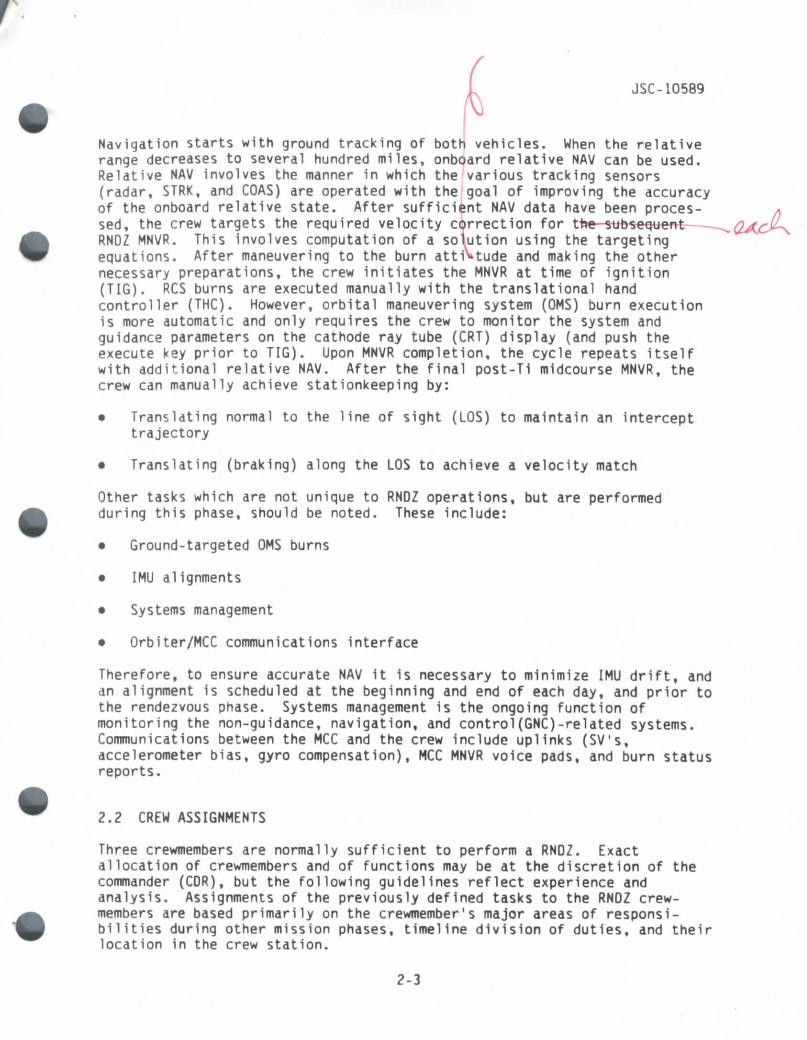
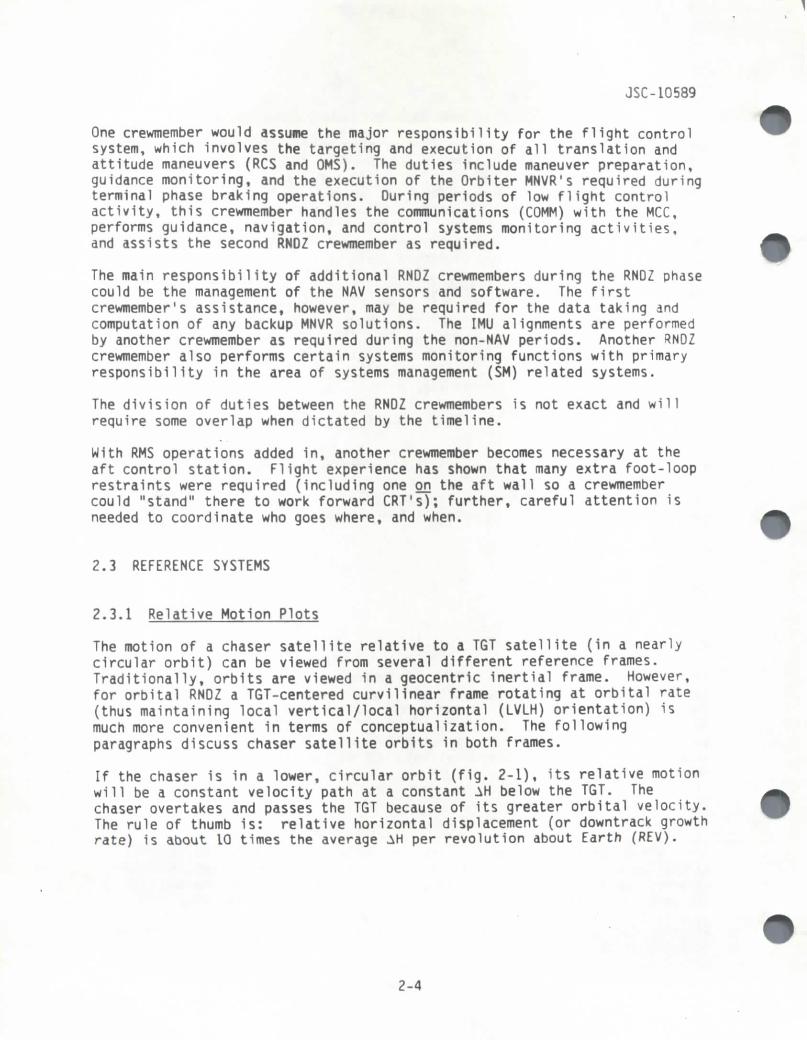
The motion of a chaser satellite relative to a TGT satellite (in a nearlycircular orbit) can be viewed from several different reference frames.Traditionally, orbits are viewed in a geocentric inertial frame. However,for orbital RNDZ a TGT-centered curvilinear frame rotating at orbital rate(thus maintaining local vertical/local horizontal (LVLH) orientation) ismuch more convenient in terms of conceptualization. The followingparagraphs discuss chaser satellite orbits in both frames.
If the chaser is in a lower, circular orbit (fig. 2-1), its relative motionwill be a constant velocity path at a constant AH below the TGT. Thechaser overtakes and passes the TGT because of its greater orbital velocity.The rule of thumb is: relative horizontal displacement (or downtrack growthrate) is about 10 times the average AH per revolution about Earth (REV).
2-4
TARGET AT TlflE A
JSC-10589
2358. ART* 2
CHASES ATTIME A
TARGET
CHASER ATTIME A
GEOCENTRIC INERT IAL TARGET-CENTERED ROTATING
Figure 2-1.- Relative motion plot, circular orbits.
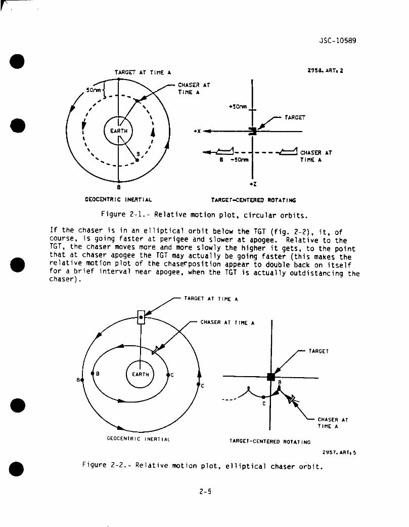
If the chaser is in an elliptical orbit below the TGT (fig. 2-2), it, ofcourse, is going faster at perigee and slower at apogee. Relative to theTGT, the chaser moves more and more slowly the higher it gets, to the pointthat at chaser apogee the TGT may actually be going faster (this makes therelative motion plot of the chase^position appear to double back on itselffor a brief interval near apogee, when the TGT is actually outdistancing thechaser).
TARGET AT TIME A
CHASER AT TIME A
TARGET
CHASER ATTIME A
GEOCENTRIC I N E R T I A L TARGET-CENTERED ROTATING
2957. ARTiS
Figure 2-2.- Relative motion plot, elliptical chaser orbit.
2-5

JSC-10589
The next step Is for the elliptical orbit of the chaser to actually touchthe target orbit (fig. 2-3). The final approach trajectory is thus seen lobe from below and ahead of the TGT. To match orbits, the chaser must thenraise its perigee to the TGT altitude by increasing its velocity (firing inthe direction of the flight path).
TARGET AT TIME A
GEOCENTRICINERT IAL
TARGET-CENTEREDROTATING
(TARGET IN CIRCULAR ORBIT) 2956.ART,5
Figure 2-3.- Tangential orbits.
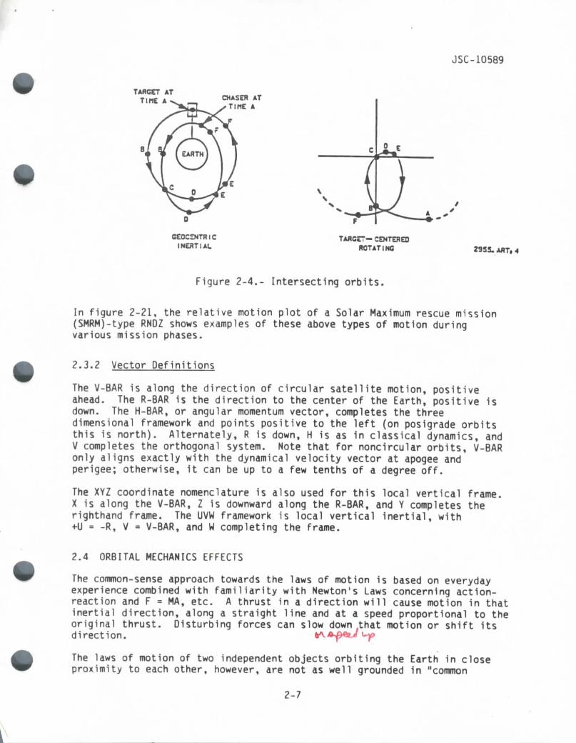
In practice, final approach trajectories utilize elliptical orbits whichcross that of the TGT (fig. 2-4). The chaser makes a final burn at apogee(the Ti burn), so intercept occurs less than 360' later. This results in a"hot" approach in which the chaser closes in on the target stationaryagainst a stellar (inertial) dark background, with a finite range rate atintercept (thus, real-life dispersions will not have as great an effect onthe trajectory as they would in the case of a minimum-energy, Hohmann-typetransfer.) At this point the crew takes manual control, bleeds down therange rate, and completes the rendezvous.
2-6
JSC-10589
TARGET ATTine A CHASER AT
TinE A
CEOCZNTRICINERT I At
TARGET— CENTEREDROTATING 2933. ART. 4
Figure 2-4.- Intersecting orbits.
In figure 2-21, the relative motion plot of a Solar Maximum rescue mission(SMRM)-type RNDZ shows examples of these above types of motion duringvarious mission phases.
2.3.2 Vector Definitions
The V-BAR is along the direction of circular satellite motion, positiveahead. The R-BAR is the direction to the center of the Earth, positive isdown. The H-BAR, or angular momentum vector, completes the threedimensional framework and points positive to the left (on posigrade orbitsthis is north). Alternately, R is down, H is as in classical dynamics, andV completes the orthogonal system. Note that for noncircular orbits, V-BARonly aligns exactly with the dynamical velocity vector at apogee andperigee; otherwise, it can be up to a few tenths of a degree off.
The XYZ coordinate nomenclature is also used for this local vertical frame.X is along the V-BAR, Z is downward along the R-BAR, and Y completes therighthand frame. The UVW framework is local vertical inertial, with•HI = -R, V = V-BAR, and W completing the frame.
2.4 ORBITAL MECHANICS EFFECTS
The common-sense approach towards the laws of motion is based on everydayexperience combined with familiarity with Newton's Laws concerning action-reaction and F = MA, etc. A thrust in a direction wil l cause motion in thatinertial direction, along a straight line and at a speed proportional to theoriginal thrust. Disturbing forces can slow down that motion or shift itsdirection.
The laws of motion of two independent objects orbiting the Earth in closeproximity to each other, however, are not as well grounded in "common
2-7
JSC- 10589
sense". Newton's Laws still apply, of course, but orbital mechanics effectsresulting from the inverse square force field often alter the "common sense"results of simple directional thrusting when viewed in the target-centered(non-inertial) rotating frame. Although the resulting relative motion isnot necessarily intuitive, it is predictable.
2.4.1 Relative Motion of Two Objects Orbiting in Proximity
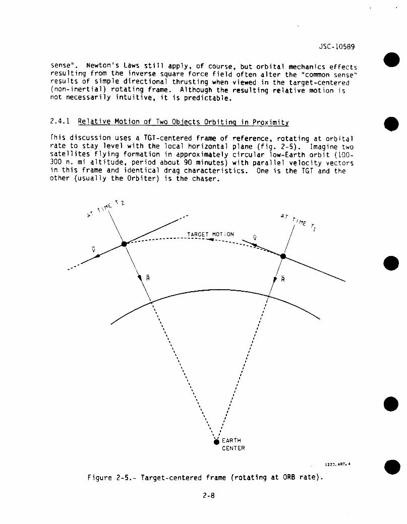
This discussion uses a TGT-centered frame of reference, rotating at orbitalrate to stay level with the local horizontal plane (fig. 2-5). Imagine twosatellites flying formation in approximately circular low-Earth orbit (100-300 n. mi altitude, period about 90 minutes) with parallel velocity vectorsin this frame and identical drag characteristics. One is the TGT and theother (usually the Orbiter) is the chaser.
EARTHCENTER
1223. ART,
Figure 2-5.- Target-centered frame (rotating at ORB rate)
2-8
JSC-10589
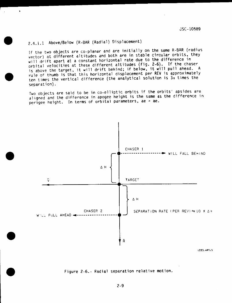
2.4.1.1 Above/Below (R-BAR (Radial) Displacement)
If the two objects are co-planar and are initially on the same R-BAR (radiusvector) at different altitudes and both are in stable circular orbits, theyw i l l drift apart at a constant horizontal rate due to the difference inorbital velocities at these different altitudes (fig. 2-6). If the chaseris above the target, it w i l l drift behind; if below, it will pull ahead. Arule of thumb is that this horizontal displacement per REV is approximatelyten times the vertical difference (the analytical solution is 3u times theseparation).
Two objects are said to be in co-elliptic orbits if the orbits' apsides arealigned and the difference in apogee height is the same as the difference inperigee height. In terms of orbital parameters, ae = ae.
A H 4
CHASER 1
W I L L FALL BEHIND
TARGET
CHASER 2WlLL PULL AHEAD
A H
SEPARATION RATE (PER REV) ** 10
1223.ART,
Figure 2-6.- Radial separation relative motion,
2-9
JSC-10589
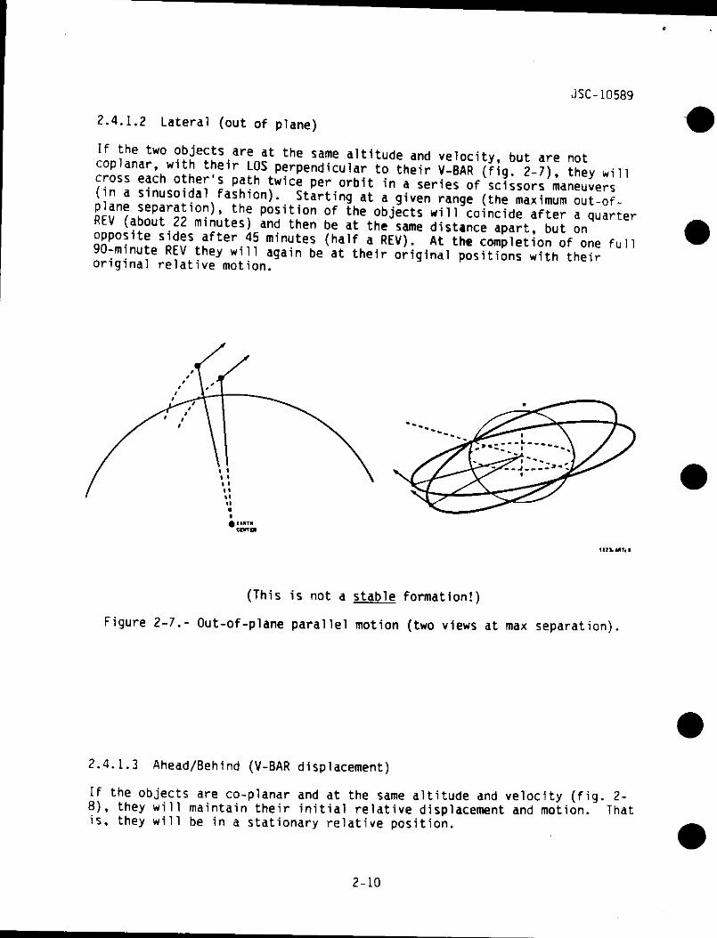
2.4.1.2 Lateral (out of plane)
If the two objects are at the same altitude and velocity, but are notcoplanar, with their LOS perpendicular to their V-BAR (fig. 2-7), they w i l lcross each other's path twice per orbit in a series of scissors maneuvers(in a sinusoidal fashion). Starting at a given range (the maximum out-of-plane separation), the position of the objects will coincide after a quarterREV (about 22 minutes) and then be at the same distance apart, but onopposite sides after 45 minutes (half a REV). At the completion of one full90-minute REV they will again be at their original positions with theiroriginal relative motion.
(This is not a stable formation!)
Figure 2-7.- Out-of-plane parallel motion (two views at max separation).
2.4.1.3 Ahead/Behind (V-BAR displacement)
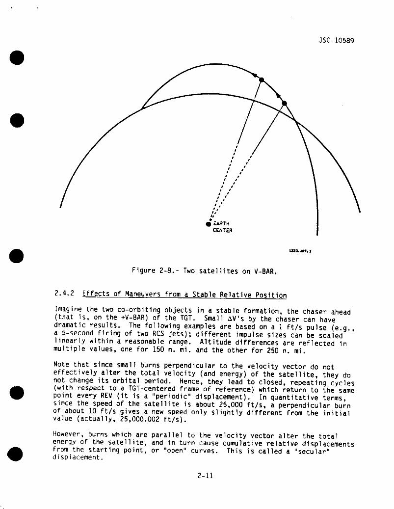
If the objects are co-planar and at the same altitude and velocity (fig. 2-8), they w i l l maintain their initial relative displacement and motion. Thatis, they w i l l be in a stationary relative position.
2-10
JSC-10589
£ARTHCENTER
tan. MTi
Figure 2-8.- Two satellites on V-BAR.
2.4.2 Effects of Maneuvers from a Stable Relative Position
Imagine the two co-orbiting objects in a stable formation, the chaser ahead(that is, on the +V-BAR) of the TGT. Small AV's by the chaser can havedramatic results. The following examples are based on a 1 ft/s pulse (e.g.,a 5-second firing of two RCS jets); different impulse sizes can be scaledlinearly within a reasonable range. Altitude differences are reflected inmultiple values, one for 150 n. mi. and the other for 250 n. mi.
Note that since small burns perpendicular to the velocity vector do noteffectively alter the total velocity (and energy) of the satellite, they donot change its orbital period. Hence, they lead to closed, repeating cycles(with respect to a TGT-centered frame of reference) which return to the samepoint every REV (it is a "periodic" displacement). In quantitative terms,since the speed of the satellite is about 25,000 ft/s, a perpendicular burnof about 10 ft/s gives a new speed only slightly different from the initialvalue (actually, 25,000.002 ft/s).
However, burns which are parallel to the velocity vector alter the totalenergy of the satellite, and in turn cause cumulative relative displacementsfrom the starting point, or "open" curves. This is called a "secular"displacement.
2-11
JSC-10589
If a burn has components in different directions, the result can be approx-imated by vector additions of the results of each component.
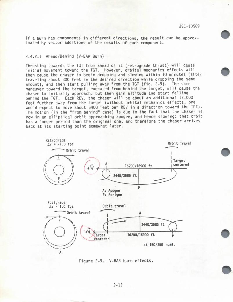
2.4.2.1 Ahead/Behind (V-BAR Burn)
Thrusting towards the TGT from ahead of it (retrograde thrust) w i l l causeinitial movement toward the TGT. However, orbital mechanics effects wi l lthen cause the chaser to begin dropping and slowing within 10 minutes (aftertraveling about 300 feet in the desired direction while dropping the sameamount), and then start pulling away from the TGT (fig. 2-9). The samemaneuver toward the target, executed from behind the target, will cause thechaser to initially approach, but then gain altitude and start fallingbehind the TGT. Each REV, the chaser will be about an additional 17,000feet further away from the target (without orbital mechanics effects, onewould expect to move about 5400 feet per REV in a direction toward the TGT).The motion (in the "from behind" case) is due to the fact that the chaser isnow in an elliptical orbit approaching apogee, and hence slowing; that orbithas a longer period than the original one, and therefore the chaser arrivesback at its starting point somewhat later.
RetrogradeAV = -1.0 fps
Orbit travel
Orbit Travel
I Targetcentered
Pos1gradeAV * 1.0 fps
A: ApogeeP: Perigee
Orbit travel
3440/3585 ft
16200/16900 ft p
at 150/250 n.mt.
Figure 2-9.- V-BAR burn effects.
2-12
JSC-10589
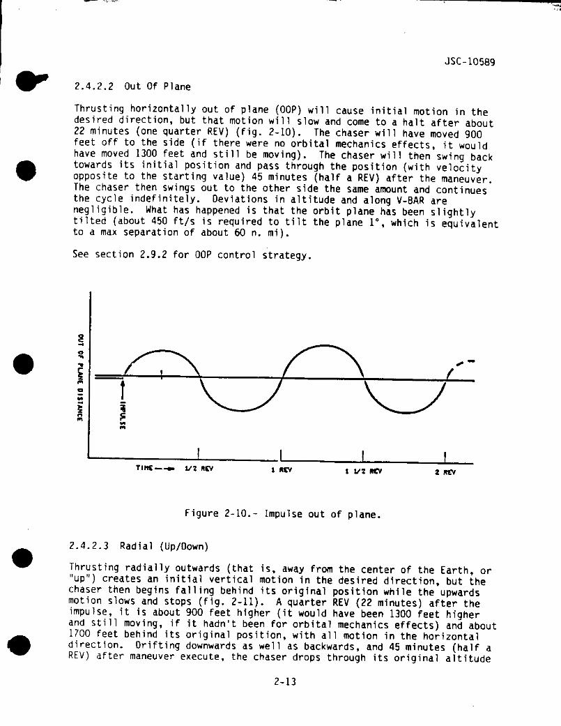
2.4.2.2 Out Of Plane
Thrusting horizontally out of plane (OOP) will cause initial motion in thedesired direction, but that motion will slow and come to a halt after about22 minutes (one quarter REV) (fig. 2-10). The chaser will have moved 900feet off to the side (if there were no orbital mechanics effects, it wouldhave moved 1300 feet and still be moving). The chaser will then swing backtowards its initial position and pass through the position (with velocityopposite to the starting value) 45 minutes (half a REV) after the maneuver.The chaser then swings out to the other side the same amount and continuesthe cycle indefinitely. Deviations in altitude and along V-BAR arenegligible. What has happened is that the orbit plane has been slightlytilted (about 450 ft/s is required to tilt the plane 1°, which is equivalentto a max separation of about 60 n. mi).
See section 2.9.2 for OOP control strategy.
S
/-̂ s^\. 1/2 fl EV 1 RCV 1 1/2 «CV 2 REV
Figure 2-10.- Impulse out of plane.
2.4.2.3 Radial (Up/Down)
Thrusting radially outwards (that is, away from the center of the Earth, or"up") creates an initial vertical motion in the desired direction, but thechaser then begins falling behind its original position while the upwardsmotion slows and stops (fig. 2-11). A quarter REV (22 minutes) after theimpulse, it is about 900 feet higher (it would have been 1300 feet higherand still moving, if it hadn't been for orbital mechanics effects) and about1700 feet behind its original position, with all motion in the horizontaldirection. Drifting downwards as well as backwards, and 45 minutes (half aREV) after maneuver execute, the chaser drops through its original altitude
2-13

JSC-10589
at a range of about 3500 feet from where it started. It then continues inthis "football" trajectory, dropping but moving forward, then rising andresuming its original position after a full orbit. The motion then repeats,subject to outside perturbations.
Thrusting radially inwards (downwards) creates the same-sized ''football11orbit which first pulls ahead and then backwards in its 90-minute cycle.
Radially outwardAV » 1.0 fps
Orbit travel Orbit travel
Targetcentered
A: ApogeeP: Perigee
860/890 ft
•3440/3560 ft
Radially InwardAV = 1.0 fps
Orbit travelOrbit travel
860/890 ft
3440/3560 ft
Targetcentered
Figure 2-11.- R thrusting effects.
2.4.3 Use of Orbital Mechanics
For final approach to a TGT anddesirable to minimize RCS plumeforward reaction control system"orbital mechanics" can be used"free" RCS translation impulses
for subsequent stationkeeping, it may beimpingement on the TGT and to minimize(FRCS) usage. In certain strategies,to obtain braking effects, somewhat like
These useful effects are achieved byactual RCS burns which can be designed to be orthogonal (at right angles) tothe chaser-target LOS. This avoids plume impingement, and if the burns canbe arranged to be +X Orbiter body axis, also avoids substantial FRCS usage.See figure 2-12.
2-14
JSC-L0589
Uf the following three techniques (orthogonal braking, R-BAR approach, andV-BAR approach), only the last is normally used in STS operations. Theothers may have important applications in future operations.
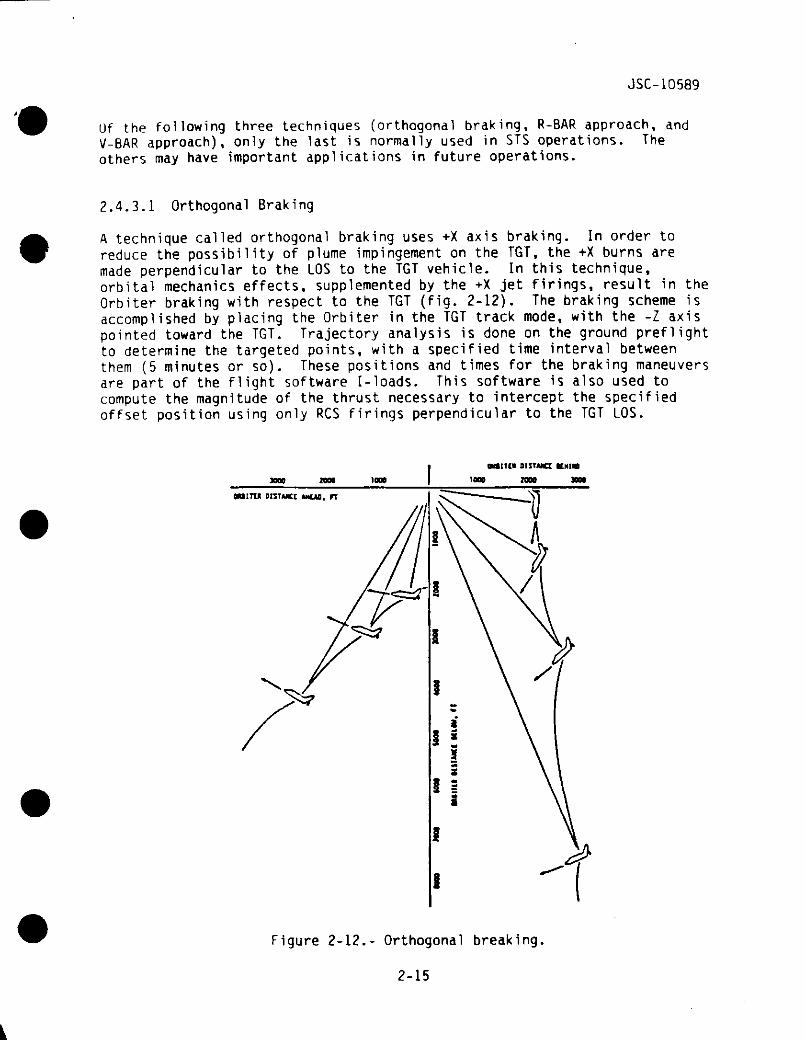
2.4.3.1 Orthogonal Braking
A technique called orthogonal braking uses +X axis braking. In order toreduce the possibility of plume impingement on the TGT, the +X burns aremade perpendicular to the LOS to the TGT vehicle. In this technique,orbital mechanics effects, supplemented by the +X jet firings, result in theOrbiter braking with respect to the TGT (fig. 2-12). The braking scheme isaccomplished by placing the Orbiter in the TGT track mode, with the -Z axispointed toward the TGT. Trajectory analysis is done on the ground preflightto determine the targeted points, with a specified time interval betweenthem (5 minutes or so). These positions and times for the braking maneuversare part of the flight software I-loads. This software is also used tocompute the magnitude of the thrust necessary to intercept the specifiedoffset position using only RCS firings perpendicular to the TGT LOS.
3000 zooo 1000 1000
OMITU DISTJUCI MOM. rr
Figure 2-12.- Orthogonal breaking.
2-15
JSC-10589
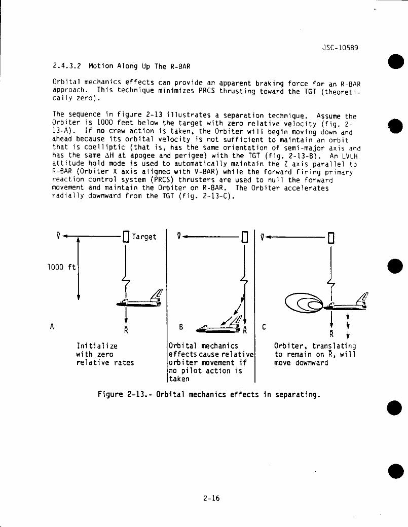
2.4.3.2 Motion Along Up The R-BAR
Orbital mechanics effects can provide an apparent braking force for an R-BARapproach. This technique minimizes PRCS thrusting toward the TGT (theoreti-cal ly zero).
The sequence in figure 2-13 illustrates a separation technique. Assume theOrbiter is 1000 feet below the target with zero relative velocity (fig. 2-13-A). If no crew action is taken, the Orbiter will begin moving down andahead because its orbital velocity is not sufficient to maintain an orbitthat is coelliptic (that is, has the same orientation of semi-major axis andhas the same AH at apogee and perigee) with the TGT (fig. 2-13-B). An LVLHattitude hold mode is used to automatically maintain the Z axis parallel toR-BAR (Orbiter X axis aligned with V-BAR) while the forward firing primaryreaction control system (PRCS) thrusters are used to null the forwardmovement and maintain the Orbiter on R-BAR. The Orbiter acceleratesradially downward from the TGT (fig. 2-13-C).
1000 ft
Target
Initializewith zerorelative rates
Orbital mechanicseffects cause rel ati veorbiter movement ifno pilot action istaken
Orbiter, translatingto remain on R, willmove downward
Figure 2-13.- Orbital mechanics effects 1n separating.
2-16
JSC-10589
V-—r Q Target
1000 ft
Initialize withrelative rates
zeroBObtain closing rate
D
Correct for -V-BAR drift
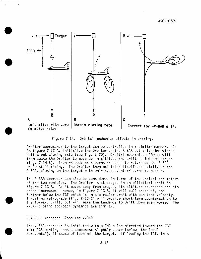
Figure 2-14.- Orbital mechanics effects in braking.
Orbiter approaches to the target can be controlled in a similar manner. Asin figure 2-13-A, initialize the Orbiter on the R-BAR but this time with asufficient closing rate (see fig. 5-20). Orbital mechanics effects w i l lthen cause the Orbiter to move up in altitude and drift behind the target(fig. 2-14-B). Then +X body axis burns are used to return to the R-BARwhile still rising. The Orbiter then maintains itself essentially on theR-BAR, closing on the target with only subsequent +X burns as needed.
The R-BAR approach can also be considered in terms of the orbital parametersof the two vehicles. The Orbiter is at apogee in an elliptical orbit infigure 2-13-A. As it moves away from apogee, its altitude decreases and itsspeed increases - hence, in figure 2-13-B, it will pull ahead of, andfurther below the TGT which is in a circular orbit with constant velocity.Thrusting retrograde (fig. 2-13-C) w i l l provide short-term counteraction tothe forward drift, but will make the tendency to drift down even worse. TheR-BAR closing approach dynamics are similar.
2.4.3.3 Approach Along The V-BAR
The V-8AR approach is initiated with a THC pulse directed toward the TGT(aft RCS canting adds a component slightly above [below] the localhorizontal), if ahead of [behind] the target. If leading the TGT, this
2-17
JSC-10589
small AV component results in a trajectory which rises a small distanceabove V-BAR before beginning to fall relative to the TGT. This normal AVcomponent is obtained from Orbiter translation cross-coupling from a -Zacceleration (toward the TGT) into the +X axis (normal to V-BAR). If nocorrections were performed at the V-BAR crossing, the Orbiter wouldeventually fall below V-BAR and move farther ahead of the TGT (dashed linein fig. 2-15). This is because the AV applied was primarily a retrogradeburn which lowers the other side of the orbit. The reduced average orbitaltitude of the Orbiter causes a difference in orbital rates (i.e., Orbitertraveling faster than target), and the Orbiter moves ahead of the TGT.Therefore, to maintain a closing rate, the crew must thrust up (normal tothe TGT LOS) at each V-BAR crossing to produce a series of trajectory hopsuntil the capture distance is achieved. Note that because of RCS cross-coupling, firing the Orbiter +X jets to maintain altitude also slows theclosing rate. (The thrusting up has the theoretical effect of reducing thegravitational acceleration on the Orbiter, which allows it to maintain thesame altitude as the TGT at a lower velocity, resulting in the Orbiter beingovertaken by the target satellite.) To stabilize the Orbiter at a desiredrange, RCS firings toward the TGT (acceleration away from the target) isrequired in order to restore full circular orbital velocity to the Orbiter.
2.5 RENDEZVOUS PARAMETERS
Sensors are used by the crew during rendezvous to obtain information aboutthe relative position of the Orbiter with respect to the TGT. Thisinformation is then utilized to determine translation corrections which maybe needed based on desired position. Some parameters can also be computedby NAV or by manipulation of timed marks of other parameters.
The parameters used are range (R), range rate ("R-OOT"), elevation (EL),azimuth (AZ), pitch inertial angle rate (EL-OOT), and roll inertial anglerate (AZ-OOT).
2.5.1 Range
Ordinarily, R is considered to be the LOS distance between the Orbitercenter of mass (c.m.) and the TGT c.m. However, the reference point for theraw data is not really the Orbiter c.m., but is the sensor itself and thisis noticeable during PROX OPS. (This offset is accounted for in GN&C FSWfor proper navigation.) The rendezvous radar (RR) (see section 3.3.4.2)provides range from the TGT to the Ku-band antenna; the closed circuittelevision (CCTV) tilt technique (section 3.3.5.3) provides distance fromTGT to the Orbiter structure (i.e., "clearance"); the angular size technique(section 3.3.6) provides range to the visual sensor (CCTV or eyeball).There can be both proportional (scale) and constant delta (offset) biases.
2-18
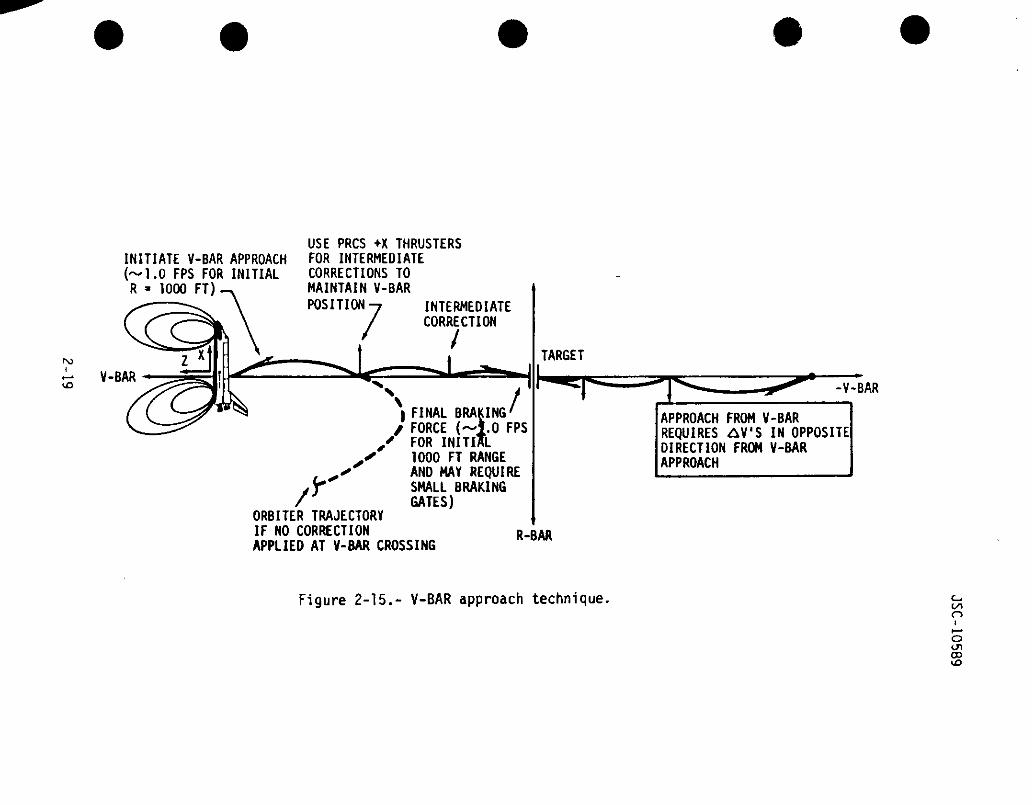
INITIATE V-BAR APPROACH(~1.0 FPS FOR INITIALR - 1000 FT)
USE PRCS +X THRUSTERSFOR INTERMEDIATECORRECTIONS TOMAINTAIN V-BARPOSITION-7 INTERMEDIATE
CORRECTION
noi
V-BAR
X| FINAL BRAKING'/ FORCE (—1.0 FPS
iKIl
fr
ORBITER TRAJECTORYIF NO CORRECTIONAPPLIED AT V-BAR CROSSING
FOR INITIJ1000 FT RANGEAND MAY REQUIRESMALL BRAKINGGATES)
TARGET
R-BAR
-V-BAR
APPROACH FROM V-BARREQUIRES AV'S IN OPPOSITEDIRECTION FROM V-BARAPPROACH
Figure 2-15.- V-BAR approach technique,C/loIt—•oU1CD
JSC-10589
2.5.2 Range Rate
R-DOT is the rate at which the range measurement is changing with respect totime; positive is an opening rate, negative is a closing rate. This can beobserved directly by a sensor (e.g., RR) or computed using successive rangemarks.
2.5.3 Elevation
2.5.3.1 Radar Elevation
The RR n u l l position is along the Orbiter -Z axis. The radar EL is then thepitch position of the radar relative to its null position (±90"); positivesense - antenna LOS motion toward the Orbiter nose, the +X axis (fig. 2-16).
2.5.3.2 COAS Elevation
COAS elevation is the vertical position (Orbiter X, Z plane), in degrees, ofthe target position in the COAS field-of-view relative (FOV) to the Orbiter-Z axis. This is assuming the COAS is aligned perfectly with the Orbiter -Zaxis. Whenever the Orbiter -Z axis is aligned parallel to the V-BAR, withthe Orbiter X axis in the TGT orbital plane, this angle provides anindication of the ±X axis thrusting required to drive the Orbiter back tothe V-BAR. See section 3.3.3 for details.
2.5.3.3 STRK Elevation
See section 3.3.1 for -Z and -Y STRK angles.
2.5.4 Azimuth
2.5.4.1 Radar Azimuth
The AZ is the roll position of the radar relative to its null position(±180°); positive sense - antenna LOS motion toward the Orbiter left wing,or -Y axis (fig. 2-16).
2-20

JSC-10589
XINO FITCH AMO IIHO MOLLOCCUM ALOCM1 TM« Z-AXIB
Figure 2-16.- Orbiter vehicle coordinate system andKu-band antenna slewing directions.
Radar EL and AZ are the target LOS angles which provide the crew with theantenna position relative to the Orbiter -Z axis. Assuming radar TRK andOrbiter attitude with -Z axis parallel to V-BAR, then EL and AZ provide anindicator of Orbiter position relative to TGT V-BAR (since at close rangesthe TGT V-BAR and Orbiter V-BAR essentially coincide), and consequently thethrusting direction required to drive back the TGT V-BAR. These angles areuseful primarily during the night side of the orbit, when the TGT is notvisible in the COAS.
2.5.4.2 COAS Azimuth
COAS azimuth is the horizontal position (Orbiter Y, Z plane), in degrees, ofthe TGT position in the COAS FOV relative to the Orbiter -Z axis. This isassuming the COAS is properly aligned. Whenever the -Z axis is alignedparallel to the V-BAR with the Orbiter X axis in the TGT orbital plane, thisangle provides an indication of the ±Y axis thrusting required to drive theOrbiter back to the V-BAR.
2.5.5 Elevation Rate
Elevation rate (EL-DOT) is the pitch inertial angle rate.toward the *X Orbiter axis.
Positive sense is
2-21
JSC-10589
2.5.6 Azimuth Rate
Azimuth rate (AZ-DOT) is the roll inertial angle rate. Positive sense istoward the -Y Orbiter axis.
EL-OOT and AZ-DOT are the components of the inertial angle rate of theOrbiter-TGT LOS, transformed into the Orbiter X, Z and Y, Z body planes,respectively.
2.6 TARGET VISIBILITY
Of great concern to naked-eye observation of a TGT is its illumination, itsposition relative to the Sun, and its position relative to the horizon.
2.6.1 IIlumination
The portion of an orbit in which a TGT is lit by the Sun can range fromlittle more than a half all the way to total {100 percent). This is afunction of target altitude, inclination, and beta angle. Sunlit (passive)illumination is critical for COAS and STRK observation.
2.6.2 Position Relative to the Sun
Looking toward the Sun makes observing a TGT very difficult, both from thedirect solar glare, the glare induced on the windows, and the fact that itis the nonilluminated side of the TGT facing the observer. No observationsare generally planned when the TGT is within 20° of the Sun, but glareconditions certainly exist even farther out.
Preferred operating relative positions (assuming low beta angle) are withthe Sun behind the observer, or off to the side of the observer-TGT line ofsight. For a situation with the Orbiter ahead of the TGT, this is satisfiedin the period between orbital sunrise and orbital noon; for an Orbiterbehind a TGT, the interval is approximately orbital noon to sunset. Thisgeometry is taken into account during operations planning.
It is also generally preferred that the TGT be a diffuse reflector ratherthan a "shiny" specular reflector. Because diffuse reflection provides moreuniform reflection at all angles, there is less concern for loss of TGTvisual for certain TGT attitudes relative to the LOS. Specular reflectionis particularly obvious from solar panels tracking the Sun.
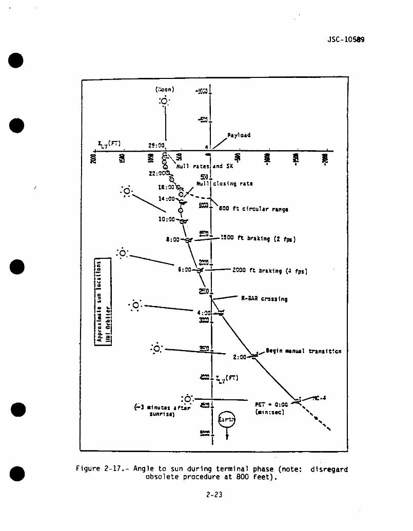
Terminal phase of the rendezvous profile is designed to optimize lightingconditions. As seen in figure 2-17, the LOS to the Sun is kept far from thetarget LOS.
2-22
JSC-10589
X^tfT)
•S3-
25.00^ X§ I f-\ -
Q Null races22:OC
? 1 S Iand $'<
Closing rati
• ' 800 ft circular range
KOO ft braking (2 fps)
2CQO ft braking (4 fps]
R-3A8 crossing
••nutl trsniltlcn
Figure 2-17.- Angle to sun during terminal phase (note: disregardobsolete procedure at 800 feet).
2-23
JSC-10589
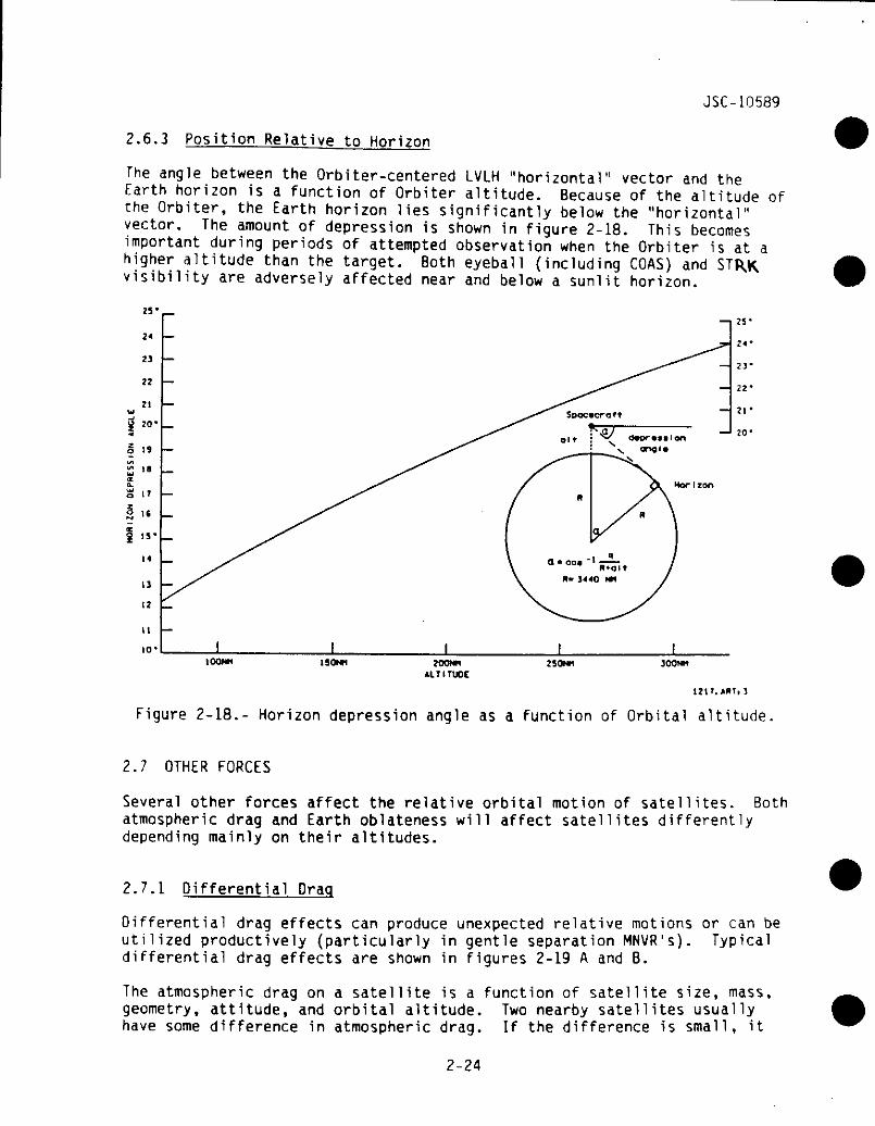
2.6.3 Position Relative to Horizon
The angle between the Orbiter-centered LVLH "horizontal" vector and theEarth horizon is a function of Orbiter altitude. Because of the altitude ofthe Orbiter, the Earth horizon lies significantly below the "horizontal"vector. The amount of depression is shown in figure 2-18. This becomesimportant during periods of attempted observation when the Orbiter is at ahigher altitude than the target. Both eyeball (including COAS) andvisibility are adversely affected near and below a sunlit horizon.
2V
24
23
22
21
20-
19
II
IT
1C
I 15>
H
13
12
11
10'tOONM 1SONM ZOONH
ALTITUDE250NM JOONH
121T.ART, S
Figure 2-18.- Horizon depression angle as a function of Orbital altitude.
2.7 OTHER FORCES
Several other forces affect the relative orbital motion of satellites. Bothatmospheric drag and Earth oblateness will affect satellites differentlydepending mainly on their altitudes.
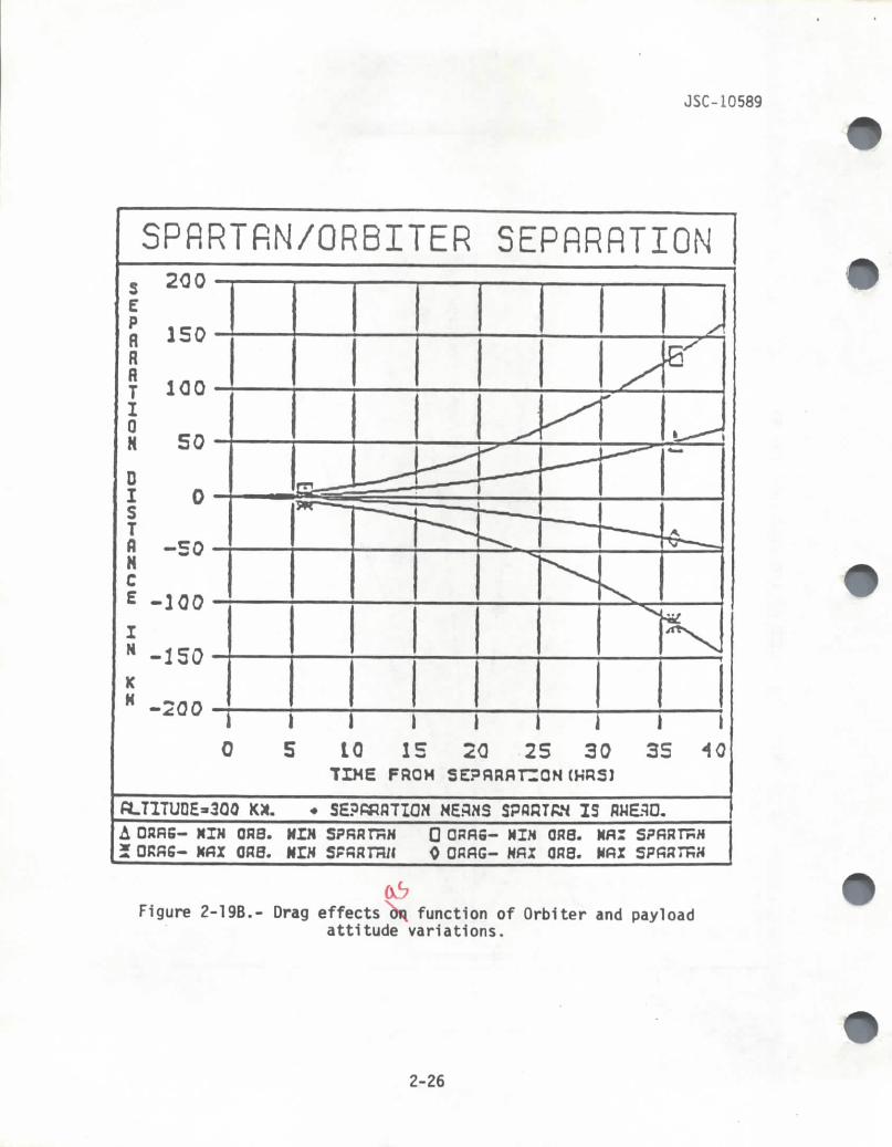
2.7.1 Differential Drag
Differential drag effects can produce unexpected relative motions or can butilized productively (particularly in gentle separation MNVR's). Typicaldifferential drag effects are shown in figures 2-19 A and B.
be
The atmospheric drag ongeometry, attitude, andhave some difference in
a satellite is a function of satellite size, massorbital altitude. Two nearby satellites usuallyatmospheric drag. If the difference is small, it
2-24

SEPARATION D ISTANCE i MM)
1 1 1-o en roLTI O W C
1 1 1C
n> 3ro J z
^O «• ^^ *D
*' ^ ™ T~ 3 -t ?
I | o S
2 ° ?> j /*~^ o *— * .'
B, $
4/1 Q. x'-i. X
C ~~** x^3 m * x ^O 2 x f\r* m + "*»A-•• 3 -^ V^
§ 2 '/0 * /-h /
o*CT *** '.̂ f
C+ _ /o> 2, /~~* ̂ /
n> /^ n t•"*• I/T '*- *** /rt> * * /a. o m *J° o- tn '
s 5"* ° '(X*
O> . l\}
CL ~o / &fr * *f
3 2 'B> j^ '^ 2 '— • /_. O /1 J^ ^
S >1 /, ' i
_.. . 1ft" 1~* 1
-"* /"~ Iro
I1
e f/ 1
/ I/ 1
1If -•f
1Jff1
» I
/ '111111
11111111111t -H
/!.1 ^0i *^i •*1 Cft
^J1 J:i '*'» 3>
(O —0 0
27 —
X
(/t•1
4- +ro tn
> in o
1 1V
\ \ \ i
lI%
» *^^5*•
*\
1111
- i•̂•tiiii%
ti
" 0 i1ttItt1\
-o
3
x E-APPROXIMATE -n z
RADAR RANGE S g7 CD
~*1 _jf^ ^^^ m_ 3)\ *
\ o\ 5
5«^ o\
V
^
^ o"*** /t's ^y
*.^i ^\
\*^
^ T3
* X,\">
\
\\O ^
I O\\» 311
•
LJl
•n3)
mt
•nr~fn3>
>i —2 -ns §
—
_^
J»
1—
r̂~•~H
-H•*, C
omo-r\-
roO•
01ro
5Orooo•z.
—
\.
68S01-O$r
JSC-10589
SPRRTRN/ORBITER SEPRRRTION200
PflflflTI0H
DISTflNCE
IH
KK -200 i l l )
S 10 15 20TIME FROM
251
30I35
I40
fiLTITUDE-300 K*. SEPRRflTIQN NESNS SPflRTRH ISA DRRS- NIH ORB. HIM
GR0. HIN SPRH77W0 ORflS- HIM QR8. Nfll SPfiRTnH0 ORfiG- MRI ORS. Mfil
06Figure 2-19B.- Drag effects^ function of Orbiter and payload
attitude variations.
2-26
JSC-10589
can be Ignored; If it is large, it can introduce separations of thousands offeet per REV.
For differential drag effects, atmospheric density is the same for bothobjects. Typically, since volume is proportional to the cube of radiuswhile area is proportional to the square of radius, and since decellerationdue to drag is proportional to area divided by mass (which is directlyrelated to volume for a constant mass density), then in general the largerthe body the less significant the drag effects if the density of the 2vehicles is about the same. For non-symmetrical objects, attitude is alsoimportant since the frontal area affects drag (e.g., the Orbiter in XLV Y-POP has about three times the drag as the Orbiter in ZLV Y-POP).
For example, a i-meter diameter tracking sphere weighing 34 pounds wouldpull ahead of the Orbiter by 3 miles per REV and drop about 1 mile per REV,at 160 n. mi.; at 120 n. mi., it would pull ahead by 15 miles per REV whiledropping 4 miles. Figures 2-19 A and B show typical SPARTAN-classdifferential drag effects.
Another example of how differential drag can cause motion which seemscontrary to "common sense" is a case involving a spacecraft which has verylow density particles (e.g., "snowflakes") separating from it. Drag willquickly cause the particles to lose energy and fall into a lower orbit wherethey will pick up speed and pull ahead of the spacecraft. An example ofthis was MA-6 in 1962. From the spacecraft, ice particles appeared to beaccelerating away forward, which in one sense they were, because their dragwas greater than that of the spacecraft. Understandably, this was notobvious at the time, and the motion of the particles (the "fireflies")caused some bafflement.
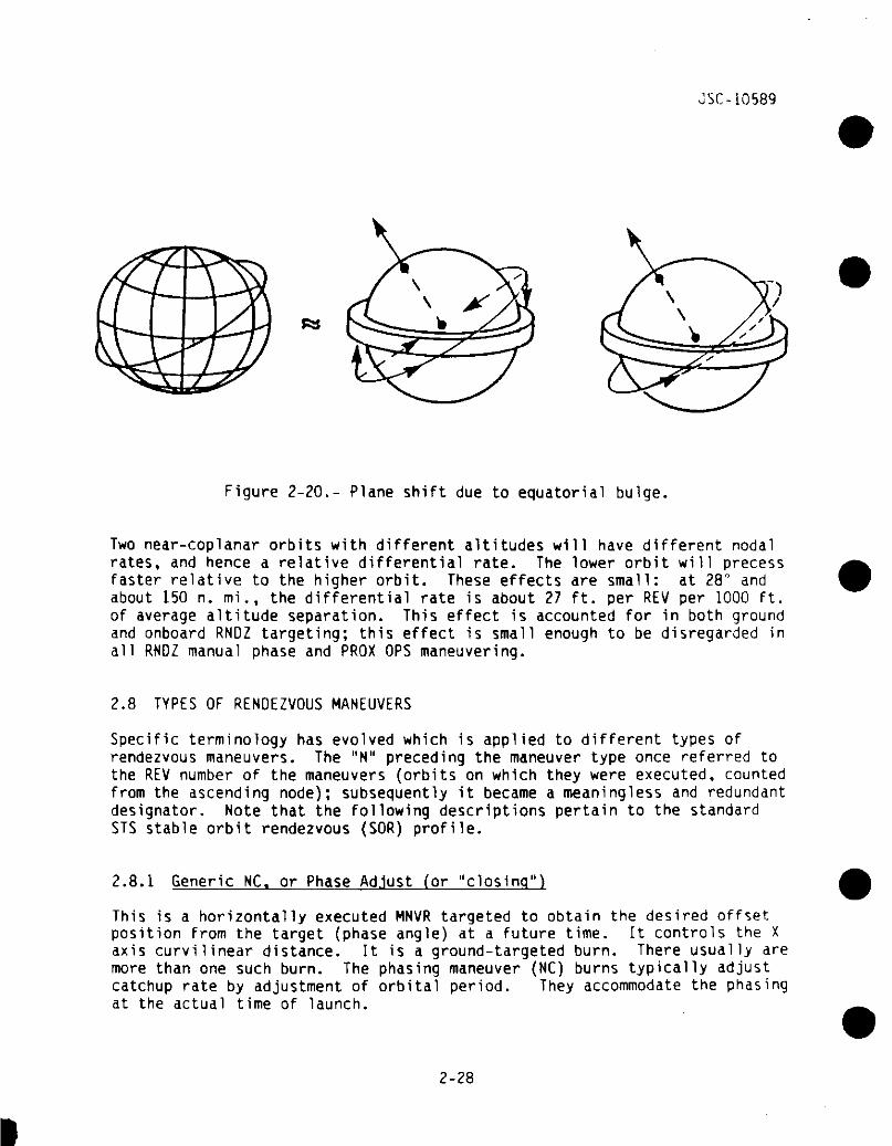
2.7.2 Differential Nodal Regression Effects
The oblateness of the Earth causes the orbital plane of a satellite inposigrade orbit to be displaced westward by several degrees per day. Themagnitude of this displacement is affected by orbital inclination andaltitude (orbits with steeper inclinations and/or higher altitudes are lessaffected by the perturbing force of the oblate mass). See figure 2-20.
Through an equation derived from geophysics principles, the precession rate(in degrees per day) can be calculated:
rate - -9.98 (cos i) (r/a)t3.5
where r = Earth radiusa = orbital semimajor axis
(assuming low eccentricity)
2-27
JSC-10589
Figure 2-20.- Plane shift due to equatorial bulge
Two near-coplanar orbits with different altitudes will have different nodalrates, and hence a relative differential rate. The lower orbit will precessfaster relative to the higher orbit. These effects are small: at 28° andabout 150 n. mi., the differential rate is about 27 ft. per REV per 1000 ft.of average altitude separation. This effect is accounted for in both groundand onboard RNDZ targeting; this effect is small enough to be disregarded inall RNDZ manual phase and PROX OPS maneuvering.
2.8 TYPES OF RENDEZVOUS MANEUVERS
Specific terminology has evolved which is applied to different types ofrendezvous maneuvers. The "N" preceding the maneuver type once referred tothe REV number of the maneuvers (orbits on which they were executed, countedfrom the ascending node); subsequently it became a meaningless and redundantdesignator. Note that the following descriptions pertain to the standardSTS stable orbit rendezvous (SOR) profile.
2.8.1 Generic NC. or Phase Ad.lust for "closing")
This is a horizontally executed MNVR targeted to obtain the desired offsetposition from the target (phase angle) at a future time. It controls the Xaxis curvilinear distance. It is a ground-targeted burn. There usually aremore than one such burn. The phasing maneuver (NC) burns typically adjustcatchup rate by adjustment of orbital period. They accommodate the phasingat the actual time of launch.
2-28
JSC-10589
2.8.2 Generic NH. or Differential Height Adjust (HA)
This is a horizontally executed MNVR targeted to a differential height fromthe TGT at some future time. It controls the Z axis distance. It is groundtargeted
2.8.3 Generic NPC, or Plane Change
This is an out-of-plane MNVR which places the chaser into the phantom planeof the TGT. The phantom plane is the actual plane of the TGT offset by theamount of differential nodal regression calculated to occur between the MNVRand the desired inplane time. In addition, the MNVR must be located at acommon node between the chaser and phantom TGT planes. If the future timeto be inplane is not identified, the MNVR will place the chaser in theactual plane of the target at the time of the MNVR. This burn controls theY axis distance. It is ground-targeted.
2.8.4 Generic NCC. or Corrective Combination
This is a Lambert-targeted MNVR to correct the chaser trajectory to achievea desired offset position from the target. It controls all axes. This MNVRis a combination of three MNVR's: NC, NH, and NPC. It is ground targetedand also targeted onboard with Orbiter sensor data.
Note that in general it is very advantageous to combine orbit adjust burnsand plane changes, since they are perpendicular to each other and theresulting burn is an RSS combination, which is usually much more economicalthan making each burn separately. However, this may not be possible if themaneuver is to be located at an orbit apsis and a common node.
2.8.5 Generic NSR. or Coelliptlc
This is a MNVR targeted to put the chaser in an orbit coelliptic to the TGT.Coelliptic is defined as a condition where there are coincident lines ofapsides and equal differential altitudes at both apogee and perigee. The"SR" of "NSR" once stood for "Slow Rate."
2.8.6 Generic Ti. or Transition Initiation (TO
This is a Lambert-targeted MNVR which places the chaser on an Intercepttrajectory with the TGT. It occurs several minutes before noon. It istargeted for 320° transfer, to achieve "hot" closing trajectory and maintaingood lighting for manual braking and proximity operations. Do not confuse"Ti" with the "Tl" designation used 1n orbit targeting; their similarity isan unfortunate coincidence.
2-29
JSC-10589
2.8.7 Generic HC. or Mldcourse
These are also Lambert-targeted maneuvers placing the chaser on an intercepttrajectory. Each midcourse MNVR corrects minor dispersions using more andmore accurate tracking data.
Note that in general, a midcourse will be made as it is realized thatintercept will not occur. If it is farther than expected, the Orbiter mustgo faster, and this is done by entering a lower orbit, so the midcoursedirection is downwards; if the target is closer than expected, the Orbitermust slow down by entering a higher orbit, and this is done by performing amidcourse correction upwards. Other requirements are second-order effects.Note that we are talking about only fractions of one complete revolutionfrom the actual midcourse maneuver point until final intercept; in the long-term, such up and down burns do not, of course, alter the total orbitalperiod, but they can and do alter the speed of the chaser along portions ofeach revolution.
2.8.8 Generic TF, or Transition Finalization
This is the second maneuver of the Lambert pair Ti - TF (or MC-TF). ThisMNVR is designed to null the relative rates between the TGT and chaser atthe intercept point. It is not a guided MNVR executed by the crew.However, the braking gates and the V-BAR stabilization burn cumulativelyapproximate a "TF burn." The term "TF" does not appear in the actual FDF.
2.9 TYPICAL RENDEZVOUS
The RNDZ is performed by making MNVR's and sensor passes.
2.9.1 Maneuvers
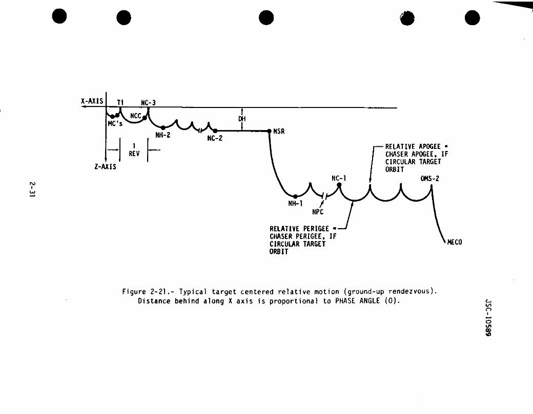
A typical RNDZ plan involves a series of maneuvers of the types describedabove. Figure 2-21 shows typical relative motion for a ground-up RNDZprofile. A typical on-orbit RNDZ profile can be seen in figures 4-1, 4-2,and 4-3.
The highest "humps" in the trajectory of the chaser represents the relativeapogee between the TGT and chaser vehicles; if the TGT is in a circularorbit, this will also be the apogee of the chaser. The lowest "humps" inthe trajectory of the chaser represent the relative perigee between the TGTand the chaser vehicles. If the TGT is in a circular orbit, this will alsobe the perigee of the chaser.
From peak to peak is one revolution (from relative apogee to relativeapogee).
Phase angle and differential height (DH) are both noted on the figure.
2-30
*
X-AXIS T1 NC-3
MC'sDH
1REV
NH-2 HC-2
Z-AXIS
rou>
NSR
RELATIVE APOGEE »CHASER APOGEE, IFCIRCULAR TARGETORBIT
OHS-2
NH-1 /NPC
RELATIVE PERIGEE -CHASER PERIGEE, IFCIRCULAR TARGETORBIT
HECO
Figure 2-21.- Typical target centered relative motion (ground-up rendezvous).Distance behind along X axis is proportional to PHASE ANGLE (0). C-.
too
oen
1JSC-10589
2.9.1.1 The Actual NC Maneuver(s)
Most RNDZ plans will contain several NC MNVR's, the first one being OMS-2.Typically, the flight dynamics officer (FOO) will try to schedule at leastone NC MNVR per flight day. The reason for multiple NC MNVR's is that theycontrol the X axis (downtrack) distance; this is the direction that isaffected most by attitude maneuvers, water dumps, mis-modeled drag, andpropagation errors because of the secular effects. Radial and out-of-planedisturbances induce periodic (cyclic) motion.
•oThe phasing profile has a great effect on the available launch window.
2.9.1.2 The Actual NH Maneuver(s)
Usually there is at least one NH maneuver in the RNOZ profile, that maneuvercontrolling the relative distance to the target altitude. Some profilesw i l l contain multiple NH maneuver^ if there are intermediate altitudes thatneed to be achieved.
2.9.1.3 The Actual NSR Maneuver
There is usually only one NSR maneuver in the RNDZ profile, although therecould be more. It is desirable to go coelliptic with the target so thatfuture maneuvers may be initiated based on orbital lighting.
2.9.1.4 The Actual NPC Maneuver
There is typically one NPC maneuver in each RNDZ profile so that the Orbiterwill be inplane with the TGT at the desired time. This applies mostly toground up RNOZ plans, since its primary purpose is to remove ascent planardispersions.
Other than being executed at a common node, placement of the NPC maneuver iscompletely arbitrary since it is designed to put the Orbiter inplane withthe TGT vehicle at Ti.
2.9.1.5 The Actual NCC Maneuver
There is only one NCC maneuver which is targeted with the onboard computersafter some sensor data has been obtained (it is also targeted on theground). It occurs 225° (about one hour) before Ti, and aims for a point48,600 feet (8 n. mi) trailing and 1,200 feet above the V-BAR, inplane withthe TGT.
2-32
JSC-10589
2.9.1.6 The Actual Ti Maneuver
There is only one Ti TF combination to initiate transition to manualphase. It begins three minutes before orbital noon, at a time determined bythe ground, and spans a 320° transfer to intercept. Current strategy placesthis burn near orbiter apogee.
2.9.1.7 The Actual Midcourse Maneuver(s)
There can be up to four midcourse maneuvers. MCI is about 8 minutes beforesunset; MC2 is at a 28.5° elevation angle to the target and is targeted witha 1251 transfer to target intercept. Wc3j4 fc&*J 6+ (& ftfe/iC&W*
2.9.1.8 The Actual TF Maneuver
This would theoretically occur about 10 minutes after MC4, but before thatpoint, the final orbit-matching burns are made manually based on range rateand out-the-window LOS to target. A generic TF burn is not targeted orperformed.
2.9.2 Out of Plane Control Theory and Practice
There w i l l always be an initial planned planar separation between a chaserorbit and the target orbit. Propulsive burns are designed to reduceunplanned out-of-plane motion to zero at final approach. Some aspects ofthis strategy were described in passing in the previous sections, but thissection addresses the issue directly and exclusively.
Section 3.5.7 discusses several aspects of using the ORB TGT function toassist in out-of-plane control on the day of rendezvous.
2.9.2.1 Initial Conditions
Between any two orbital planes there is a line of nodes which is defined bythe intersection of those two planes. That line moves naturally due toorbital mechanics effects such as differential nodal regression, if the twoorbits have different altitudes. Usually the chaser is in a lower orbit,and its strategy is to move into a phantom plane which itself will shiftinto the actual target plane due to these orbital mechanics effects. Seefigure 2-22.
Initial OOP dispersions are due mainly to ascent yaw steering for ground-upRNDZ's and to IMU alignment or maneuver trim errors on deploy/retrievalRNDZ's.
2-33
JSC-10539
Reserved for Fig. 2-22
TIME
Manualphasebegins
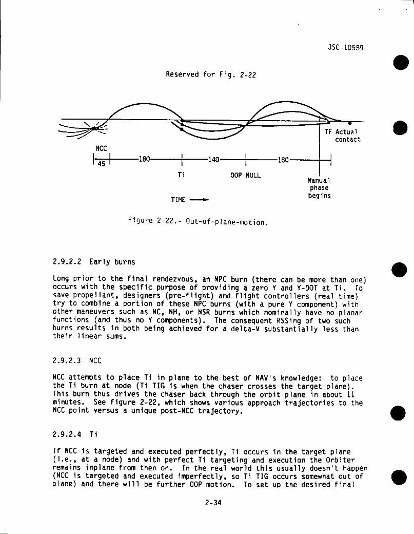
Figure 2-22.- Out-of-plane-motion
2.9.2.2 Early burns
Long prior to the final rendezvous, an NPC burn (there can be more than one)occurs with the specific purpose of providing a zero Y and Y-DOT at Ti. Tosave propellant, designers (pre-flight) and flight controllers (real time)try to combine a portion of these NPC burns (with a pure Y component) withother maneuvers such as NC, NH, or NSR burns which nominally have no planarfunctions (and thus no Y components). The consequent RSSing of two suchburns results in both being achieved for a delta-V substantially less thantheir linear sums.
2.9.2.3 NCC
NCC attempts to place T1 1n plane to the best of NAV's knowledge: to placethe Ti burn at node (Ti TIG is when the chaser crosses the target plane).This burn thus drives the chaser back through the orbit plane in about 11minutes. See figure 2-22, which shows various approach trajectories to theNCC point versus a unique post-NCC trajectory.
2.9.2.4 T1
If NCC is targeted and executed perfectly, Ti occurs in the target plane(i.e., at a node) and with perfect Ti targeting and execution the Orbiterremains inplane from then on. In the real world this usually doesn't happen(NCC is targeted and executed imperfectly, so Ti TIG occurs somewhat out ofplane) and there will be further OOP motion. To set up the desired final
2-34
JSC-10589
approach conditions, the next node must be set to a point 140° ahead, sofinal intercept ("TF") then occurs in plane after 320° (140° + 180°) oftravel. This aim point, TF, is where the chaser would physically Interceptthe target if no manual braking burns occurred; it would occur at aboutMC4 + 10, with a relative velocity of about 5 ft/s, approaching relativeapogee (but not yet there). Naturally, manual phase operations (e.g.,braking gates) slow the final approach well before this point and thussignificantly delay contact beyond this time. If there is any OOP motion atTF, it must be detected out the COAS or on RR angle rates, and nulledmanually. Usually, however, the Orbiter and target are essentially coplanarby this point.
Because of NAV dispersions and NCC trims, Ti TIG usually occurs at somenonzero Y point (i.e., measurably off the target plane). In that case, toachieve the desired mode 320° (and also 140°) in the future the Ti Ycomponent will push the chaser away from the target plane (it may already beheaded away), and maximum separation will occur 50° (about 12 minutes) afterTi TIG. The size of this maximum separation is proportional to how far theTi burn turned out to be out of plane (fig. 2-22 shows this effect).
Since MCI is also targeted to the same node as Ti was, it does notsignificantly alter the subsequent nodes, if REL NAV supporting Ti and Titrimming was very good.
2.9.2.5 OOP Null
The final node prior to TF occurs about halfway between MCI and MC2(nominally, MCI + 13 minutes). At this point, relative navigation datadisplayed to the crew on SPEC 33 is used to perform the burn: first, thecrew notes the actual in-plane time (Y becomes zero), and then the crewmonitors the proper size of their manual RCS burns made to prevent furtherout-of-plane swings (Y-DOT is driven to zero). The burn can be made over aspan of several minutes without seriously impacting the out-of-planesituation.
If this burn is not performed properly, the same Y-DOT can and must bemanually removed half a REV (45 minutes) later, post-MC4, with the crew inthe manual phase (nominally, RR data allows NAV to produce reliable Y andY-DOT values, and the target can also be viewed out the COAS). Thiscorrection can also be facilitated by knowledge of the former Y-DOT at themissed OOP point or by nulling OOP rates as soon as possible after thenominally scheduled time.
Procedural matters for executing this burn are discussed in section 4.1.54(and fig. 4-14).
2-35
JSC-10589
2.9.2.6 Proximity Operations
For final approach, and for stationkeeping, plane control is an entirelymanual function based on visual/RR LOS motion. The crew should have the OOPsituation under control by V-BAR arrival, and certainly by the time DAP LOWZ is entered. The best method is to use small THC pulses to start thetarget moving toward the center of the COAS and then, as it crosses thecenterline, input an equal number of pulses in the opposite direction tostop the motion.
Any remaining Y-DOT is of sufficiently small scale that it causes essen-tially no orbital mechanics effects (the short time scale of PROX OPSmaneuvering also induces this) and therefore "OOP" (any Y components ofrelative position) now can be handled as pure inertial relative motion andcorrected directly as detected.
?-9.3 Typical Sensor Passes
Prior to the first acquisition on by on-board sensors, all information onthe Orbiter-target relative state is computed (both on the ground and on-board) from separate inertial Orbiter and target SV's produced by groundtracking; the onboard SV's are uplinked from the MCC (the target SV is notused on board until entry into RNOZ NAV). To facilitate accurate ground NAV(and hence the best possible SV's), there can be periods when some Orbiteractivities may be restricted to the extent of avoiding propulsive activitiessuch as vents, excessive attitude maneuvering, and water dumps.
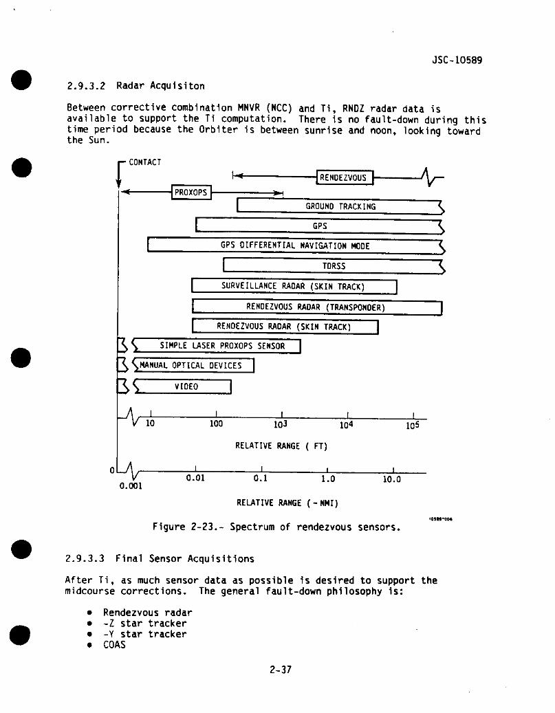
The strategy of onboard sensor passes is to progress to successively moreprecise knowledge of the Orbiter-target relative state by use of a sequenceof sensors and appropriate navigation software (see fig. 2-23).
Note that sensor data history (when and if data was acquired and how manymarks were received) is one of the two criteria for when to abort the RNDZ(see section 4.4); propellent is the other criteria.
2.9.3.1 First On-board Acquisition
Prior to NCC, 2 sensor passes are desired (typically star tracker) tosupport the first onboard targeted MNVR, NCC. These sensor data reduceerrors in the relative state caused by ground tracking inaccuracies,maneuver trim errors, translatlonal cross-coupling, and trajectorydispersions.
The fault-down philosophy for these sensor passes is:
• -I Star tracker• -Y Star tracker• COAS
2-36
JSC-10589
2.9.3.2 Radar Acquisiton
Between corrective combination MNVR (NCC) and Ti, RNDZ radar data isavailable to support the Ti computation. There is no fault-down during thistime period because the Orbiter is between sunrise and noon, looking towardthe Sun.
i- CONTACT
RENDEZVOUS
PROXOPS -*H
GROUND TRACKING
GPS
RENDEZVOUS RADAR (SKIN TRACK)
SIMPLE LASER PROXOPS SENSOR
\L OPTICAL DEVICES |
VIDEO ]1
10 100 1Q3 1Q4
RELATIVE RANGE ( FT)
vGPS DIFFERENTIAL NAVIGATION MODE
TDRSS
SURVEILLANCE RADAR (SKIN TRACK)
RENDEZVOUS RADAR (TRANSPONDER)
105
0.01 10.00.001
0.1 1.0
RELATIVE RANGE (-NMI)
Figure 2-23.- Spectrum of rendezvous sensors
2.9.3.3 Final Sensor Acquisitions
After Ti, as much sensor data as possible is desired to support themidcourse corrections. The general fault-down philosophy is:
• Rendezvous radar• -Z star tracker• -Y star tracker• COAS
2-37

JSC-10589
2.10 Pre-Day-of-Rendezvous Navigation
An appreciation of the impact of pre-day-of-rendezvous ground trackingon support of the initial conditions on rendezvous day (in particular,state vectors) can be useful in understanding certain constraints on thetimeline. This afterthought is meant to complete this handbook'sdiscussion of RNDZ NAV issues.
Generic NAV accuracies and rendezvous tracking requirements are definedin NSTS 07700, VOL XIV, Appendix 6. These are considered to be very con-servative. Mission-specific analyses always are performed for rendezvousflight design. Specific target-related tracking requirements will be inspecific PIP's. Detailed ground procedures and NAV-related informationcan be found in "ON-ORBIT GROUND NAVIGATION CONSOLE HANDBOOK", JSC IN f20768, and in the "FDO CONSOLE HANDBOOK", from which the followingtreatment is adapted.
The philosophy for rendezvous is to go into any maneuver or targetingphase with the best possible state vector, especially as the day ofrendezvous approaches. Every additional tracking site provides more datato update the ground's knowledge, and will be utilized even if it is thefirst station after a maneuver. Phasing between the chaser and thetarget is the hardest dynamic process to control, and this requiresprecise knowledge of the object's semimajor axis (and hence its period).That element must be periodically determined (requiring several REV's ofquiet tracking) and then adjusted as needed with an NC burn.
Although there is no single pre-defined tracking arc for a rendezvousprofile, the FDO's will be trying to have fresh Orbiter and TGT SV'sprior to the preliminary maneuvers plan. The TGT SV tends to change verylittle with time (typically there are no attitude maneuvers, vents,etc.), so a SV which is several REV's old is still considered adequatefor computations. But the quality of the Orbiter SV can depend onparticular on-orbit crew activities.
The main unmodeled perturbations on the Orbiter's trajectory areattitude maneuvers. It is thus desirable to minimize them on the eveningbefore rendezvous day, after that day's NC phasing burn. This meanseliminating standard IMO alignments (which require an attitude maneuverthat cross-couples into unwanted translation). IMU alignments can beaccomplished instead by taking stars of opportunity during the sleepperiod with the Orbiter nose in a north or south orientation.
Water dumps introduce small impulses, so they cannot be permitted priorto critical maneuvers unless the induced SV errors can be tracked outbefore the maneuver computation. The effects of water dumps on Orbitertrajectory have not been predictable. An alternate procedure is to runthe flash evaporator (FES), which has very little effect on trajectory.
By observing these constraints, the Orbiter will hit the desired offsebon rendezvous morning for the last NC burn before Ti, and the FDO won'tget any trajectory surprises. Following several more periods ofinbensive ground tracking of both vehicles, the Orbiter itself willbegin on-board tracking of the target (see section 2.9).
2-38