jpss-1 viirs solar diffuser witness sample brf calibration ... · the brf and brdf results for the...
TRANSCRIPT
JPSS-1 VIIRS Solar Diffuser Witness Sample BRF Calibration using a Table-top Goniometer at NASA GSFC
Jinan Zeng*a, James Butlerb, Xiaoxiong Xiongb, and Nathan Kelleyc
aFibertek Inc, 13605 Dulles Technology Dr., Herndon, VA 20171; bGoddard Space Flight Center, Greenbelt, MD, 20771; cScience Systems and Applications Incorporation, Lanham, MD, 20706
ABSTRACT
In support of the prelaunch calibration of the Joint Polar Satellite System-1 (JPSS-1) Visible Infrared Imaging Radiometer Suite (VIIRS), the Bidirectional Reflectance Factor (BRF) and Bidirectional Reflectance Distribution Function (BRDF) of a VIIRS solar diffuser (SD) witness sample were determined using the table-top goniometer (TTG) located in the NASA GSFC Diffuser Calibration Laboratory (DCL). The BRF of the sample was measured for VIIRS bands in the reflected solar wavelength region from 410 nm to 2250 nm. The new TTG was developed to extend the laboratory’s BRF and BRDF measurement capability to wavelengths from 1600 to 2250 nm and specifically for the VIIRS M11 band centered at 2250 nm. We show the new features and capabilities of the new scatterometer and present the BRF and BRDF results for the incident/scatter test configuration of 0°/45° and for a set of angles representing of the VIIRS on-orbit solar diffuser calibration. The BRF and BRDF results of the SD witness were used to assist in finalizing the set of BRF values of J1 VIIRS SD to be used on-orbit. Comparison of the BRF results between the JPSS-1 VIIRS SD witness sample and the flight SD panel was made by varying different sample clocking orientations and by analyzing the ratio of BRF to total hemispherical reflectance in effort to minimize the uncertainty of the extrapolated flight BRF value at 2250 nm. Furthermore, differences between the prelaunch BRF results and those used in the VIIRS on-orbit BRF lookup table were examined to improve the VIIRS BRF calibration for future missions.
Keywords: BRF, BRDF, Table-top goniometer, solar diffuser, reflective solar band, total hemispherical reflectance, sample clocking
1. INTRODUCTION In this paper, we summarize the work of the BRF/BRDF calibration for a JPSS1 VIIRS Solar Diffuser (SD) witness sample. This calibration is the first time that BRF measurements were acquired for the VIIRS SD witness sample covering all the solar reflective bands from M1 to M11, I1 to I3 at their central wavelengths. The SD Witness BRF measurements at the Rotation Telescope Assembly (RTA) view angle of 37.9° were completed at one of the VIIRS on-orbit solar incident angles using the TTG system. The measurements of the TTG are NIST traceable and were internally validated using BRDF reciprocity at the 0°/55.6° and 55.6°/0° configurations. The 8° spectral total hemispherical reflectance (THR) of the witness sample was also measured using a spectral reflectometer, and the relationship of 0°/45° BRF and THR result was used to verify the interpolation/extrapolation method of determining the BRF at those wavelengths for which BRF was not measured. The SD Witness BRF at two out-of-plane configurations and at one set of solar incident angles BRDF shows an azimuthal angle dependence (i.e. a clocking effect) of the BRF, similar to that observed in the flight SD BRF results3. These issues were addressed in estimating the measurement uncertainty and finalizing an average BRF result within the different solar incident angles. Verification and clarification of the interpolation/extrapolation method are of significance as a guideline to the future solar diffuser BRF calibrations with impacts on methodology and testing approach.
1.1. General Introduction
The solar diffuser assembly (SDA) on the J1 VIIRS is the key component for performing on-orbit radiometric calibration at solar reflective wavelengths from 410 nm to 2250 nm using the Sun as the source3,4,5. The on-orbit radiance calibration of the instrument relies on the BRF of the SDA at specific solar angles and at a fixed viewing angle of 37.9°. Any variation of the SDA during the prelaunch calibration phase could impact the quality and delivery of the BRF lookup table. Two SD witness samples were deployed in the vicinity of the SDA to track any possible effects from during ambient and thermal vacuum testing. Following these tests, one SD witness sample was removed from the inside of the VIIRS scan cavity. This SD witness sample was the one tested by GSFC for BRF, the results of which are reported in this paper. Following the GSFC tests, the sample was sent to Raytheon for UV exposure/BRF tests to simulate the
*[email protected]; phone 1 301 614-6600
https://ntrs.nasa.gov/search.jsp?R=20190002298 2020-04-18T06:50:50+00:00Z
effects of on-orbit solar radiation exposure. The BRF of the J1 VIIRS flight SDA was characterized at the on-orbit RTA view angle and at the six wavelengths from 400 nm to 1700 nm, and at the SDSM view angle from 400 nm to 900 nm. No measurements were made on the flight SDA at 2250 nm for band M11. The goal of the BRF measurement of the SD witness sample is to validate the SDA BRF results for those solar reflective bands that the flight SD was measured, combine all results to finalize a complete set of BRF values including the BRF for M11 at 2250 nm, and provide the associated uncertainty analysis.
1.2. Requirements of VIIRS solar diffuser measurement
The J1 VIIRS witness solar diffuser BRF measurements were made at 11 wavelengths exactly or closely corresponding to the central wavelengths for VIIRS bands M1 through M11 and also at several additional wavelengths measured by NIST to enable scale transfer from a lab standard. The filtered lamp, coherent tunable, and coherent fixed wavelength light sources on TTG system were used in the measurements of the J1 VIIRS witness solar diffuser BRF. Silicon photodiode, standard InGaAs, and extended InGaAs detectors with sphere-input were employed to cover the different spectral ranges as detailed in Table 1.
Table 1. Wavelengths, Light Sources and Detectors Used in the Measurement of J1 VIIRS Witness Solar Diffuser BRF
1.3. JPSS1 VIIRS SD Witness sample description
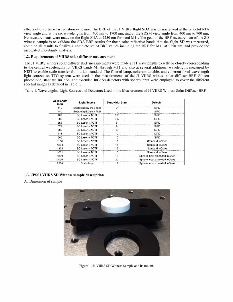
A. Dimension of sample
Figure 1. J1 VIIRS SD Witness Sample and its mount.
As shown in the photograph of Figure 1, the J1 VIIRS SD Witness sample is a 1” diameter 1/4” thick piece of space grade Spectralon. In the sample coordinates, the BRF measurement is required at an angle of incidence (AOI) of 55.6° and at an angle of viewing (AOV) of 37.9°, which was converted from the solar incident angle of declination angle 15° and azimuth angle 13.6° in the spacecraft coordinates. Such a large incident angle needs the input beam size from light sources to be less than 14.4 mm diameter without losing light due to the elongated beam shape on the sample. Transmission of the SD witness sample was also observed by shining the visible lasers and observing the transmitted light on the sample backside. The effect of the lack of a back covering on the witness SD may cause a small difference in the witness and flight SD BRF data. In the photograph of the J1 VIIRS SD Witness of Figure 1, a visible mark on the sample’s side was used as a fiducial to maintain the sample orientation for our tests. However, the relationship of the orientation between the J1 VIIRS flight solar diffuser and its witness sample was unknown, which may lead to a variation in BRF due to different azimuth angles in the SDA and the SD witness sample measurements.
2. TEST OF J1 VIIRS SOLAR DIFFUSER WITNESS SAMPLE 2.1. Spectrophotometer
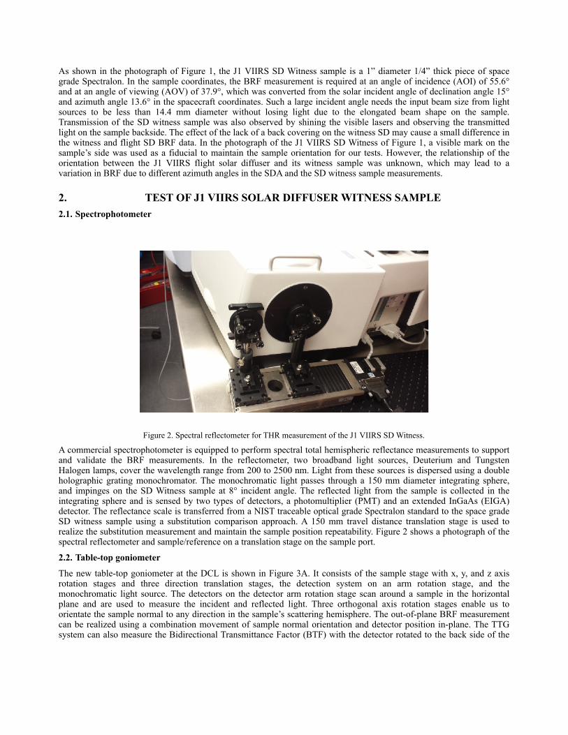
Figure 2. Spectral reflectometer for THR measurement of the J1 VIIRS SD Witness.
A commercial spectrophotometer is equipped to perform spectral total hemispheric reflectance measurements to support and validate the BRF measurements. In the reflectometer, two broadband light sources, Deuterium and Tungsten Halogen lamps, cover the wavelength range from 200 to 2500 nm. Light from these sources is dispersed using a double holographic grating monochromator. The monochromatic light passes through a 150 mm diameter integrating sphere, and impinges on the SD Witness sample at 8° incident angle. The reflected light from the sample is collected in the integrating sphere and is sensed by two types of detectors, a photomultiplier (PMT) and an extended InGaAs (EIGA) detector. The reflectance scale is transferred from a NIST traceable optical grade Spectralon standard to the space grade SD witness sample using a substitution comparison approach. A 150 mm travel distance translation stage is used to realize the substitution measurement and maintain the sample position repeatability. Figure 2 shows a photograph of the spectral reflectometer and sample/reference on a translation stage on the sample port.
2.2. Table-top goniometer
The new table-top goniometer at the DCL is shown in Figure 3A. It consists of the sample stage with x, y, and z axis rotation stages and three direction translation stages, the detection system on an arm rotation stage, and the monochromatic light source. The detectors on the detector arm rotation stage scan around a sample in the horizontal plane and are used to measure the incident and reflected light. Three orthogonal axis rotation stages enable us to orientate the sample normal to any direction in the sample’s scattering hemisphere. The out-of-plane BRF measurement can be realized using a combination movement of sample normal orientation and detector position in-plane. The TTG system can also measure the Bidirectional Transmittance Factor (BTF) with the detector rotated to the back side of the

sample. The TTG system is equipped with SiPD, standard InGaAs, and extended InGaAs detectors operating across the spectral range from 300 nm to 2500 nm.
Figure 3. The photographer of the Table-Top Goniometer (A) and its light sources (B).
Monochromatic light is generated by a supercontinuum laser with acoustic optic tunable filters (AOTF) and laser line tunable filters (LLTF) from 460 nm to 2000 nm, and by a laser driven broadband Xe lamp with narrow band pass filters from 300 nm to 450 nm. The typical bandwidth of these light sources is 5 to 15 nm as shown in Figure 3B. A monochromator-based light source is also being developed to further narrow the bandwidth down to sub nanometer or less in the spectral wavelengths of interest. In addition, there are several fixed wavelength diode lasers available at 413 nm, 850 nm, 1240 nm, 1550 nm, and 2300 nm. The TTG system was aligned with a Si quadrant detector, an IR positioning sensor, and the input beam size was checked with a CCD beam camera and a Pyrocam beam profiler. A broadband wire grid polarizer is used to generate orthogonal polarized input light, which is used to average out the polarization dependence in the BRDF measurement. Since coherence in the longer wavelength laser sources may cause speckle issues in the BRDF measurements, a spatial averaging method is adopted for speckle suppression.
2.3. Test methodology
The BRDF of the J1 SD witness sample was determined through comparison to the NIST traceable Spectralon reference. An Energetiq EQ-99FC laser-driven plasma lamp source, a supercontinuum laser with acoustic-optic tunable filter (AOTF), and a 2250 nm diode laser were used to cover all 11 VIIRS reflective solar bands (RSB) from M1 to M11, I1 to
I3. Measurements at additional wavelengths were acquired to improve the NIST BRF scale transfer. The BRDF measurement equation is shown below:
(1)
Since three different detectors (i.e. SiPD, InGaAs, and sphere-input EIGA) were needed to cover all the RSB wavelengths from 400 nm to 2250 nm, the absolute BRDF of the J1 VIIRS SD Witness was realized using a scale transfer method with the NIST traceable BRDF scales. Each detector system has its own geometric parameters for the absolute BRDF measurement. The BRDF transfer approach cancels out the geometric parameters for each detector, and eliminates the need for an input power measurement. Fortunately, the reflectance of the J1 VIIRS SD Witness made of space-grade Spectralon is very similar to that of the NIST reference standard of optical grade Spectralon, so there is no significant difference expected in the BRDF scale transfer. In the BRDF measurement, the scattered light from a sample at a specific viewing angle is measured with the monitor to account for light source drift while the same scatter measurement of the reference is also made for the BRDF scale transfer. At first, the NIST traceable BRDF scale in the 0°/45° configuration was transferred from the NIST standard to the SD Witness. With the transferred BRDF scale of the SD Witness, the BRDF measurement at the AOI of 55.6° in-plane geometries was performed for all the bands. One of the specific VIIRS solar incident angles (Dec 15°, AZ 13.6°) was chosen to conduct the out-of-plane BRDF in the configuration of 55.6°/37.9° required by the prelaunch calibration. The BRF equation is given in the following:
(2)
We also measured the total hemispherical reflectance for the J1 VIIRS SD witness sample to validate the BRDF result. With the BRDF results of AOI 0° and 55.6°, we obtained an agreement less than 1 % with the BRDF reciprocity. The spectral BRF at 0°/45° was also consistent with the total hemisphere reflectance.
3. RESULTS AND DISCUSSIONS In this section, BRDF results for validation of the TTG system are presented, and the relationship between 8° total hemispherical spectral reflectance and the BRF in different configurations such as 0°/45° and 55.6°/37.9° is discussed to extrapolate the BRF at 2250 nm. Two out-of-plane configurations of the BRDF measurement at the specific solar incident angles (Dec 15°, AZ 13.6°) were used, and the results show a sample clocking effect, which is discussed to estimate the uncertainty budget.
3.1. Validation of BRDF measurement system using BRDF reciprocity
(3)
As shown in Eqn. 3, the BRDF is the ratio of the differential reflected radiance to the differential incident irradiance, and has units of inverse steradians. If the surface does not polarize the incident flux, is uniform, and there are no magnetic fields present, then Helmholtz reciprocity is satisfied based on the energy conservation law and is expressed below:
( ) ( )( )
( )( )
BRDFAD
GG
SSBRF
rrr
i
i
rriirrrii π
θσλ
σλ
σλ
σλφθφθπσλφθφθ =××=
cos;;
;,;,,,
,;,,,2
(4)
If the above conditions are met, Helmholtz reciprocity is reliable enough to use as a check on the correct performance of experiments, in contrast with the usual situation in which the experiments are tests of a proposed law. Through the solar reflective bands, the BRDF measurements were made using different light sources, and various detectors, which should be validated.
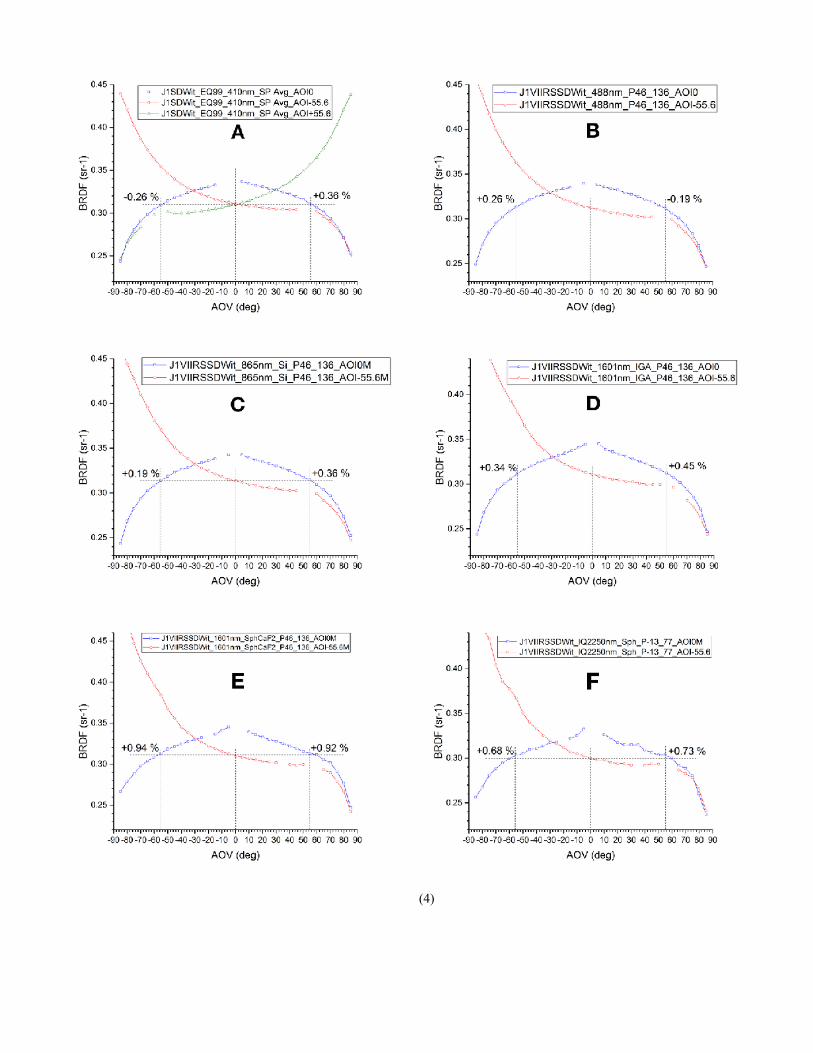
Figure 4. BRDF results from J1 VIIRS SD witness at 410 nm, 488 nm, 865 nm, 1601 nm, and 2250 nm with the AOI of 0° and 55.6° in plane.
Figure 4 shows six graphs of BRDF results from the J1 VIIRS SD witness at 410 nm, 488 nm, 865 nm, 1601 nm, and 2250 nm at AOIs of 0° and 55.6°, which are used to validate the BRDF reciprocity of the TTG system for different combinations of light source and detector. Since the supercontinuum (SC) laser is unable to generate enough output in the blue and UV region of < 450 nm, a UV enhanced laser-driven Xe lamp source with narrow bandpass filters was used to cover that wavelength range. The beam size of the lamp source is less than 10 mm diameter, which was sufficiently small to guarantee that the beam spot underfilled the 1 inch diameter J1 VIIRS SD witness sample at the AOI of ± 55.6°. Figure 4A shows the 410 nm (M1) BRDF results at AOI of 0° and ± 55.6° with the combination of Silicon photodetector and the UV enhanced broadband source. The difference of BRDF among the configuration of 0°/± 55.6° and ± 55.6°/0° is about ± 0.3 %. Figure 4B and 4C demonstrate good agreement in BRDF reciprocity at 488 nm (M3) and 865 nm (M7) at the AOI of 0° and 55.6° with the combination of Silicon photodetector and the SC laser using the VIS-NIR AOTF. A 10 mm diameter Silicon photodetector was employed in these measurements. The BRDF results agreed well even though a different spot size was created on the sample surface and imaged on the Si detector. From 1100 nm to 1700 nm, a 5 mm diameter standard InGaAs detector with thermoelectric cooler (TEC) was used for the BRDF measurements shown in Figure 4D. The BRDF results at 1601 nm using the standard IGA detector also validate the BRDF reciprocity with the combination of IGA detector and SC laser with the SWIR AOTF. An extended InGaAs detector with the integrating sphere input was used for measurements of BRDF from 1700 nm to 2500 nm. Figure 4F shows the BRDF results at 2250 nm for the AOI of 0° and 55.6° using a fixed wavelength diode laser at 2250 nm and the sphere-input EIGA detector. Figure 4E shows the BRDF results at 1601 nm in the same geometry using the supercontinuum laser with SWIR AOTF and a sphere-input EIGA detector. The BRDF reciprocity of the TTG system at the other specific wavelengths was also maintained. In the BRDF measurement, the coherent laser induced speckle effect was suppressed using a spatial averaging approach, however the speckle effect tended to increase at the longer SWIR wavelengths as shown in Figure 4. After validation of the TTG system, the BRDF calibration was conducted for all the VIIRS solar reflective bands from 410 nm to 2250 nm.
3.2. Relationship of reflectance factors, 8°/THR and BRF
Given the known technical challenges of measuring BRDF beyond 1600 nm, the ratio of 0°/45° BRF and 8°/THR of a Spectralon has been used in the testing of several satellite instruments to extrapolate the instrument SD BRF beyond 1600 nm. This approach assumes a linear relationship between BRF and THR and has been used to determine the BRF of M11 at its 2250 nm central wavelength. An 8°/THR spectrum measures the total reflectance in a 2𝛑 solid angle with directional incident light at a near normal 8° AOI. This quantity is sometimes used to evaluate the spectral evolution of BRF in a specific solid angle. The 0°/± 45° BRF measurement uses normal incident light, and a viewing angle of ± 45°, which is in the middle of the 0° to ± 90° viewing angle range. The 0°/± 45° BRF is close to the average of the BRF from 0° and ± 90° if the sample is Lambertian/isotropic; therefore, it should be proportional to the 8° THR value in an ideal case. The following sections examine the spectral relationship between 8°/THR and 0°/45° BRF for an in-plane configuration, as well as a 55.6°/37.9° in out-of-plane configuration.
3.2.1 Spectral variation of 0°/45° BRF comparing to 8°/THR in the in-plane configuration
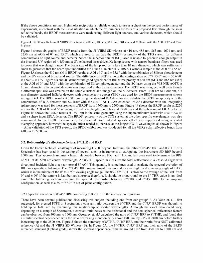
There have been several publications discussing this subject including one from our group1,2,3. As Yoon et. al.1 first suggested, for pressed PTFE or Spectralon, a constant ratio between the 6°/THR and the 0°/45° BRDF was thought to hold up to 1600 nm by examining this relationship at shorter wavelengths. Although the exact ratio could vary, depending on a sample of Spectralon, a constant ratio between the directional and the hemispherical reflectance factors can be observed from 400 nm to 1600 nm. Georgiev et. al.2 calculated the ratio of 0°/45° BRF to 8°/THR, and found that a similar spectral dependence with the ratio decreasing monotonically above 1900 nm by ~1% at 2400 nm before further increasing up to the 2500 nm. Figure 5 shows the summary of 8°THR, 0°/45° BRF, and their ratio for a NIST calibrated reference (A) and the J1 VIIRS SD Witness (B). In Figure 5A, the 8°/THR, 0°/45° BRF and their ratio of the BRDF reference standard (Optical grade) shows the spectral dependence remains around 1.02 from 450 nm to 1800 nm and
then decreases to 1 % more beyond 2300 nm. Similarly, the results of the J1 VIIRS SD Witness sample (Space grade) are shown in Figure 5. The ratio is constant around 1.02 before it starts decreasing at 2000 nm. In addition, the ratio of 0°/45° BRF and 8°/THR for both samples is seen to drop about 1 % at the wavelengths shorter than 400 nm. The deviation of the ratio of 0°/45° BRF and 8°/THR from the constant ratio of 1.02 occurs in the spectral region with significant spectral THR changes. The spectral THR change between VIS NIR and SWIR is about 3 % to 5 %. Near normal input light is able to penetrate the bulk scattering sample deeper, and the chemical absorption features at < 400 nm and beyond 1800 nm are enhanced.
Figure 5. Summary of 0°/45° BRF, 8°/THR, and their ratio for a NIST calibrated reference and the J1 VIIRS SD Witness.
3.2.2 Spectral variation of 55.6°/37.9° BRF comparing to 8° THR in the out-of-plane configuration
Figure 6. Summary of 8°/THR, 55.6°/37.9° BRF, and their ratios in two out-of plane configurations for J1 VIIRS SD Witness.
As discussed in the previous section, the constant ratio of 0°/45° BRF and 8°/THR from 400 nm to 1600 nm is maintained in the in-plane configuration for the NIST white diffuse reference and the J1 VIIRS SD Witness, and a deviation of 1 % from that constant ratio is observed from 1800 to 2300 nm. We examined the spectral variation of the

ratio between the 8°/THR and 55.6°/37.9° BRF in the out-of-plane geometry, which is the RTA VIIRS solar diffuser on-orbit calibration. The summary of 55.6°/37.9° BRF, 8°/THR, and their ratio in two out-of plane geometries for J1 VIIRS SD Witness is shown in Figure 6. Since the relative azimuthal orientation between the J1 VIIRS SDA and SD Witness is unknown, one of the solar angles (Dec 15° and AZ 13.6°) was selected at which to perform the BRDF measurement. In lab coordinates, the out-of-plane configurations of 55.6°/37.9° with two pitch angles ± 24° in term of roll, pitch, and yaw rotation are used to examine the BRDF results in different orientations. This corresponds to mirror image, symmetric geometries with respect to each other and is equivalent to a measurement of sample clocking with a fixed input light direction and scattering view. Due to the various possible orientations of the BRDF measurements, the constant ratio of 55.6°/37.9° BRF and 8°/THR shows about 2 % difference, 1.05 for the pitch angle + 24°, and 1.03 for he pitch angle − 24°. The constant ratio of the 8°/THR and 55.6°/37.9° BRF holds as expected from 1100 nm to 1600 nm, but the decrease of the ratio beyond 1800 nm is about 2 %. Besides the absorption change of the THR, the larger incident beam spot at the AOI of 55.6° in the out-of-plane configuration may contribute to a further decrease in the ratio. Moreover, the characterization of the BRDF also tends to be more specular as the wavelength increases in the SWIR.
3.3. Azimuth angle dependence (Clocking effect) of BRF
The azimuth angle dependence (i.e. the clocking effect) of the BRF has been a technical challenge in the measurements of this study. Even though the VIIRS RTA and SDMS viewing angles are fixed, the seasonal solar angle changes cause the BRF to change with azimuth angle. If the sample is non-isotropic in scattering, a clocking effect is seen in which the sample’s BRF varies strongly with azimuth. In the upper portion of Figure 7, the different solar angles lead to the BRF changes from 1.02 to 1.06 observed from the SDA BRF calibration. As mentioned in section 3.2.2, one of the solar angles (Dec 15° and AZ 13.6°) was selected for the BRF calibration of the SD Witness, which meets the requirements of the 55.6°/37.9° BRF with two mirror symmetric out-of-plane geometries. As shown in Figure 7, the variation of BRF in the two configurations of 55.6°/37.9°/± 24° is roughly 3 %, which is due to non-isotropic scatter related to the two clocking angles of the measurements. This is very similar to the BRF behavior observed from the J1 VIIRS flight SDA3. The BRF result (i.e. the solid squares) of J1 VIIRS SD Witness in the configuration 0°/45° shows similar trending to that (i.e. the solid circles) in the configuration of 55.6°/37.9°/+24°. The J1 VIIRS SD witness BRF results in the configuration of 55.6°/37.9°/± 24° have more data points beyond 1600 nm, which can be used to determine the BRF final results and support the uncertainty analysis for the J1 VIIRS SD BRF calibration.
Figure 7. Comparison of BRF variations due to azimuth angle dependence (Clocking effect).
3.4. Finalization of BRF results
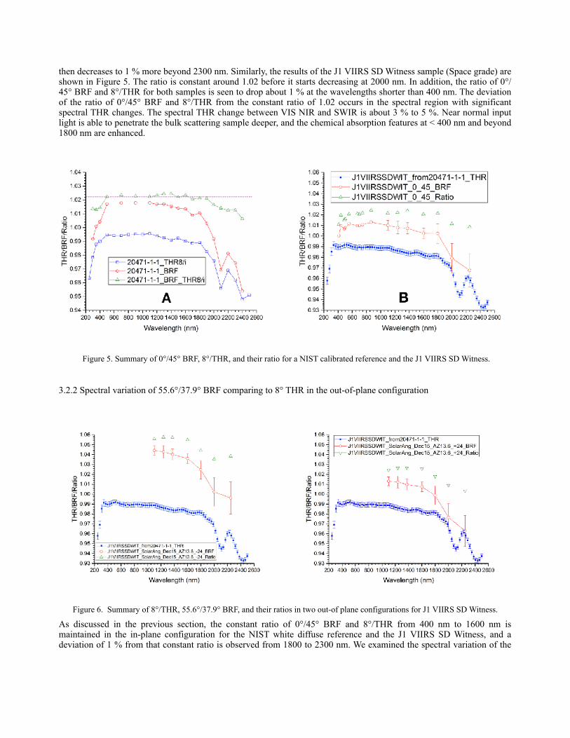
The complete set of GSFC and Raytheon BRF data are presented in Figure 8. In this figure, the 0°/45° BRF data for the VIIRS diffuser was fit to the on-orbit solar diffuser angle BRF for the two azimuths at wavelengths of 1100 nm, 1237
nm, 1375 nm and 1601 nm. This produced two BRF data sets which were combined in a weighted average and fit to the 422nm to 1626 nm BRF data measured by Raytheon. This produced a VIIRS witness solar diffuser BRF at 2250 nm of 0.9828. Also shown in the figure is the BRF calculated using the Raytheon measured BRF at 1626 nm multiplied by the ratio of the GSFC measured THR values at 2250 nm and 1626 nm. As expected, this produced a higher BRF than that obtained from the weighted average of the BRF measurements (i.e. 1.004 versus 0.9828).
Figure 8. GSFC and Raytheon (RT) BRF measurements of the J1 VIIRS witness solar diffuser at the on-orbit angles of 15° solar declination/13.6° azimuth, 55.6° incidence and 37.9° scatter. The GSFC BRF at the VIIRS on-orbit angles for the two azimuth (or clocking) angles are fit to the GSFC 0°/45° BRF at the following wavelengths: 1100 nm, 1237 nm, 1375 nm, and 1601 nm. These fits produce two GSFC BRF data sets covering wavelengths from 410 nm to 2250 nm. These data sets are combined in a weighted average to fit the Raytheon BRF data from 422 nm to 1626 nm. The 2250 nm predicted by this averaging and fitting process is 0.9828.
4. UNCERTAINTY ANALYSIS
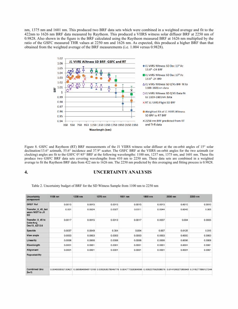
Table 2. Uncertainty budget of BRF for the SD Witness Sample from 1100 nm to 2250 nm
This table lists the uncertainty components, and evaluates the contributions to the uncertainty budget from 1100 nm to 2250 nm. Since we use a BRDF scale transfer approach, the uncertainty of the NIST calibrated BRDF transfer scale is first on the list. The NIST BRDF standard was mostly calibrated in the configuration of 0°/45°, which is not the geometry of J1 VIIRS SD BRF measurement. The BRDF scale transfer between the J1 VIIRS SD Witness and the NIST reference was made in the 0°/45° configuration which produces the second uncertainty component. For the J1 VIIRS SD witness sample, the BRDF in the out-of-plane geometry of 55.6°/37.9°/± 24° was realized using the transferred BRDF scale in the 0°/45° configuration which is listed as the third component. A spatial averaging method was used for speckle suppression, and the standard deviation of the spatial averaging changes from 0.4 % to 1.5 % within the SWIR which is the major contributor to the combined uncertainty. Several minor uncertainty contributors are the view angle, linearity, wavelength, and alignment accuracies. The combined uncertainty of the BRF measurements is from 0.5 % to 1.6 % (k=1) in the wavelength range of 1100 nm to 2250 nm.
5. CONCLUSIONS We completed the J1 VIIRS SD Witness BRDF measurements at one set of on-orbit solar angles (Dec 15°, AZ 13.6°) for all the RSB using the TTG system, supported the determination the BRF of M11 at 2250 nm, and provided an uncertainty analysis for that determination. During the tests, we also validated the TTG system using BRDF reciprocity and investigated the relationship of reflectance factors including a 0°/45° in-plane BRF and 8°/THR, and a 55.6°/37.9°/± 24° BRF out-of-plane configuration and 8°/THR. We also examined the azimuth angle dependence (i.e. clocking effect) of the BRF at two out-of-plane configurations. The VIIRS witness solar diffuser BRF at 2250 nm was determined to be 0.9828 with an uncertainty of 1.6 % (k=1).
REFERENCES
1. H.W. Yoon, D.W. Allen, G.P. Eppeldauer, and B.K. Tsai, “The extension of the NIST BRDF scale from 1100 to 2500 nm,” Proc. SPIE 7452, 745204-1-12 (2009).
2. G.T. Georgiev, J.J. Butler, K. Thome, C. Cooksey, and L. Ding, “Establishing BRDF calibration capabilities through shortwave infrared,” Proc. SPIE 10402, 10402N-1-11 (2017).
3. V. Murgai, L. Johnson, E.M. Moksun, “BRDF characterization of solar diffuser for JPSS J1 using PASCAL,” Proc. SPIE 9218, 921812-1-10 (2014).
4. Vijay Murgai, Lindsay Johnson, and Staci Klein Earth Observing Systems XXII, edited by James J. Butler, Xiaoxiong (Jack) Xiong, Xingfa Gu, Proc. of SPIE Vol. 10402, 104021M · © 2017
5. Murgai, V., Nixt, J. M., Moskun, E. M., Jones, C. M., Payton, C. E., and CdeBaca, J. D., “PASCAL: Instrument for accurate precise characterization of Lambertian materials”, Reflection, Scattering, and Diffraction from Surfaces II, edited by Zuhan Gu, Leonard M. Hanssen, Proc. of SPIE Vol. 7792, 77920X · (2010)