jps variable speed pumps - zodiac pool systems/media/225d... · pda •firmware ... • firmware...
TRANSCRIPT

INSTALLATION/PROGRAMMING/AFFINITY LAW
JPS VARIABLE SPEED PUMPS
2
Zodiac Academy [email protected]
www.zodiacacademy.com
Zodiac® Pool Systems, Inc. 1-800-822-7933 Regional Extension_________________ www.ZodiacPoolSystems.com
Instructor: _____________________________________Email:___________________________
Sales person: ___________________________________Phone:__________________________
Sales person: ___________________________________Phone:__________________________
Sales person: ___________________________________Phone:__________________________
Sales person: ___________________________________Phone:__________________________
Service Manager: ________________________________Phone:__________________________
Service Manager: ________________________________Phone:__________________________

IMPORTANT SAFETY INSTRUCTIONSThe information contained in this technical guide is intended for Zodiac trained service personnel only. Electrical installation and repairs should only be performed by a certified electrician or Zodiac trained professional. and must comply with all national electric codes (NEC®, Canadian, etc.). state and local law, ordinances, codes and regulations.
If you have not received training, do not attempt any of the electrical repairs presented in this document. Contact Zodiac Pool Systems, Inc. at 1-800-822-7933 for assistance.
Read and follow all instructions carefully.When servicing equipment, basic safety precautions should always be followed including those listed below.
TO REDUCE THE RISK OF ELECTRICAL SHOCK:• Disconnect main power to pool equipment area prior to any service or repairs.
• Keep all electrical equipment at least 10 feet (3m) from inside wall of pool or spa.
• Connect equipment only to a receptacle (cord models) or circuit (hardwired) protected by a ground fault circuit interrupter (GFCI).
• Use only copper conductors and supply wires suitable for the specific device.
• Replace damaged power cord(s) immediately and use only identical replacement parts.
• Do not bury power cord(s). Position cord(s) to minimize abuse from lawn mowers, hedge trimmers and other equipment.
• Do not install or service equipment if precipitation is present or imminent.
TO REDUCE EQUIPMENT WATER PRESSURE HAZARD:• Always turn pump off to release pressure prior to removing or installing in-line equipment.
• To avoid equipment damage, do not exceed water pressure (psi) specifications for the device.
To reduce the risk of injury, do not permit children to operate, handle or play on equipment.

2HP Variable Speed Pump
High Efficiency , Permanent Magnet, TEFC , Variable
Speed Motor
2 Inch Union or Internal Threads
Ergonomic Handles
Adjustable Base Options Available
Tool Free Drain Plugs For Easy Winterization
High Profile Lid Handles
10:00AM PUMP IS OFF PRESS RESET OR MENU

High Efficiency, Permanent Magnet, TEFC, Variable Speed Motor
2 x 2.5” Unions No Nipples Required
Premium Wet End with Installer & User Friendly
Features
Auxiliary Circuit
Tool Free Drain Plugs For Easy Winterization
40% Larger Basket Reduces Maintenance & Increases
Efficiency
2.7 Total Horsepower
Jandy RS485
Ergonomic Handles
2.0 HP Variable Speed Pump
High Efficiency , Permanent Magnet, TEFC , Variable
Speed Motor
2 - 3 Inch Unions
Ergonomic Handles
High Profile Lid Handles
Automation Options…
Tool Free Drain Plugs For Easy Winterization
Variable Speed Pump (1.5 HP & 2.0 HP, and SVRS options available)
Large Smooth Trap Basket
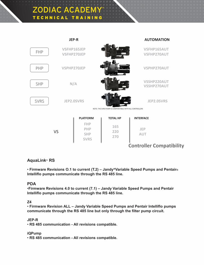
Controller Compatibility
AquaLink® RS • Firmware Revisions O.1 to current (T.2) – Jandy®Variable Speed Pumps and Pentair® Intelliflo pumps communicate through the RS 485 line. PDA •Firmware Revisions 4.0 to current (7.1) – Jandy Variable Speed Pumps and Pentair Intelliflo pumps communicate through the RS 485 line. Z4 • Firmware Revision ALL – Jandy Variable Speed Pumps and Pentair Intelliflo pumps communicate through the RS 485 line but only through the filter pump circuit. JEP-R • RS 485 communication - All revisions compatible.
iQPump • RS 485 communication - All revisions compatible.
FHP VSFHP165JEP VSFHP270JEP
VSFHP165AUT VSFHP270AUT
PHP VSPHP270JEP VSPHP270AUT
SHP VSSHP220AUT VSSHP270AUT N/A
PLATFORM TOTAL HP INTERFACE
VS
FHP PHP SHP
SVRS
165 220 270
JEP AUT
NOTE: THE SVRS PUMP IS COMPANTABLE WITH ALL CONTROLLERS
SVRS JEP2.0SVRS JEP2.0SVRS
JEP-R AUTOMATION

Plumbing
Minimum 2 times pipe diameter for discharge
Sweep Elbow Minimum 4 times pipe diameter into pump! Also, if possible, plumb larger pipe on the suction side than on the discharge side.
STEALTH STEALTH
Sweep Elbow
Good Plumbing Installation
Air Lock
STEALTH
Poor Plumbing Installation

FloPro VSP Base Jandy VS FloPro Variable Speed Pump Series VS-FHP
8
Notes:

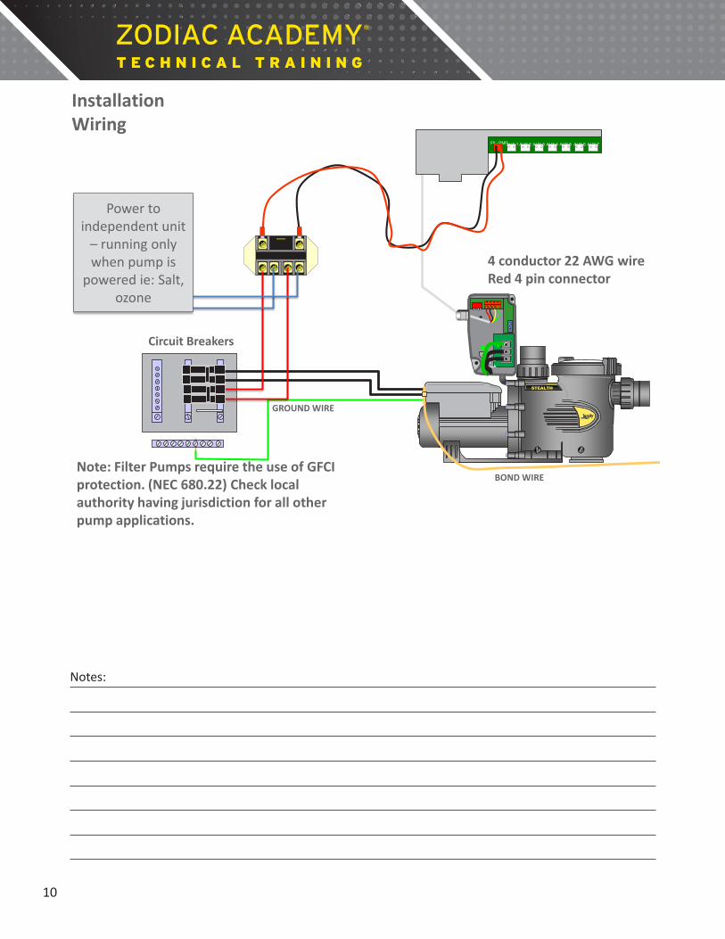
Electrical
General
GROUND WIRE
BOND WIRE
STEALTH
Circuit Breakers
4 conductor 22 AWG wire
Installation Wiring Controller of choice: JEP-R, RS, PDA, or Z4
Note: Filter Pumps require the use of GFCI protection. (NEC 680.22) Check local authority having jurisdiction for all other pump applications. Zodiac recommends the Siemens/Murray QF220A 20 amp breaker.
9
Notes:
GROUND WIRE
BOND WIRE
STEALTH
Circuit Breakers
4 conductor 22 AWG wire Red 4 pin connector
Installation Wiring
Note: Filter Pumps require the use of GFCI protection. (NEC 680.22) Check local authority having jurisdiction for all other pump applications.
L2 L1
FIL- PMP
AUX 1
AUX 2
AUX 3
AUX 4
AUX 5
AUX 6
AUX 7
Power to independent unit
– running only when pump is
powered ie: Salt, ozone
10
Notes:
MENU SELECT
L2 L1
L2 L1
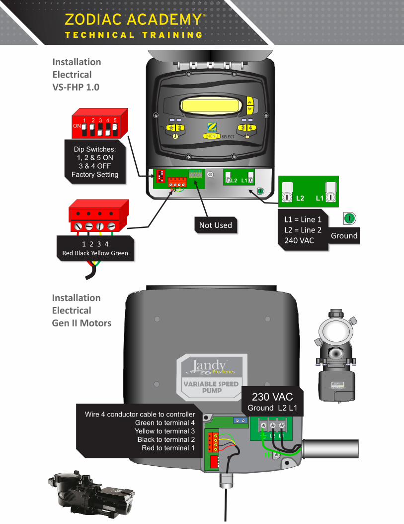
L1 = Line 1 L2 = Line 2 240 VAC Ground
1 2 3 4 Red Black Yellow Green
Not Used
Installation Electrical VS-FHP 1.0
®
1 2 3 4 5 ON
Dip Switches: 1, 2 & 5 ON 3 & 4 OFF
Factory Setting
L2 L1
Wire 4 conductor cable to controller Green to terminal 4 Yellow to terminal 3 Black to terminal 2
Red to terminal 1
®
Pro Series
VARIABLE SPEED PUMP
230 VAC Ground L2 L1
Installation Electrical Gen II Motors
L1 L2
®
Pro Series
VARIABLE SPEED PUMP
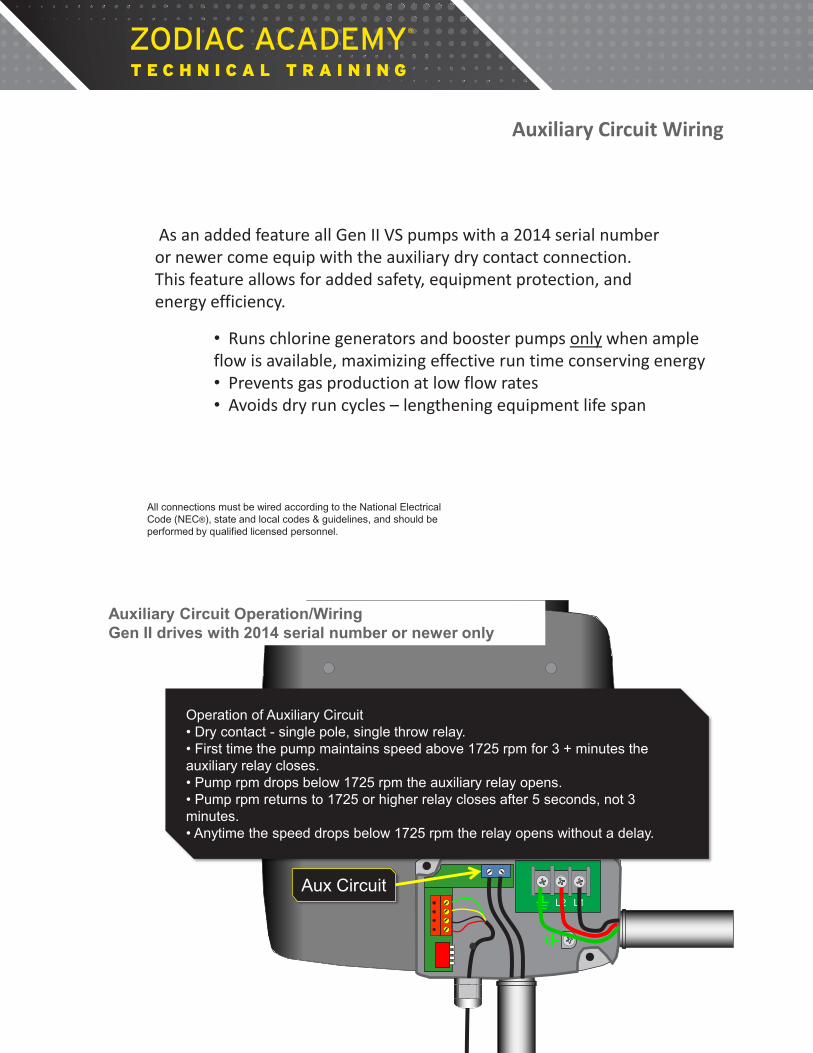
Auxiliary Circuit Wiring
As an added feature all Gen II VS pumps with a 2014 serial number or newer come equip with the auxiliary dry contact connection. This feature allows for added safety, equipment protection, and energy efficiency.
All connections must be wired according to the National Electrical Code (NEC®), state and local codes & guidelines, and should be performed by qualified licensed personnel.
• Runs chlorine generators and booster pumps only when ample flow is available, maximizing effective run time conserving energy • Prevents gas production at low flow rates • Avoids dry run cycles – lengthening equipment life span
L2 L1
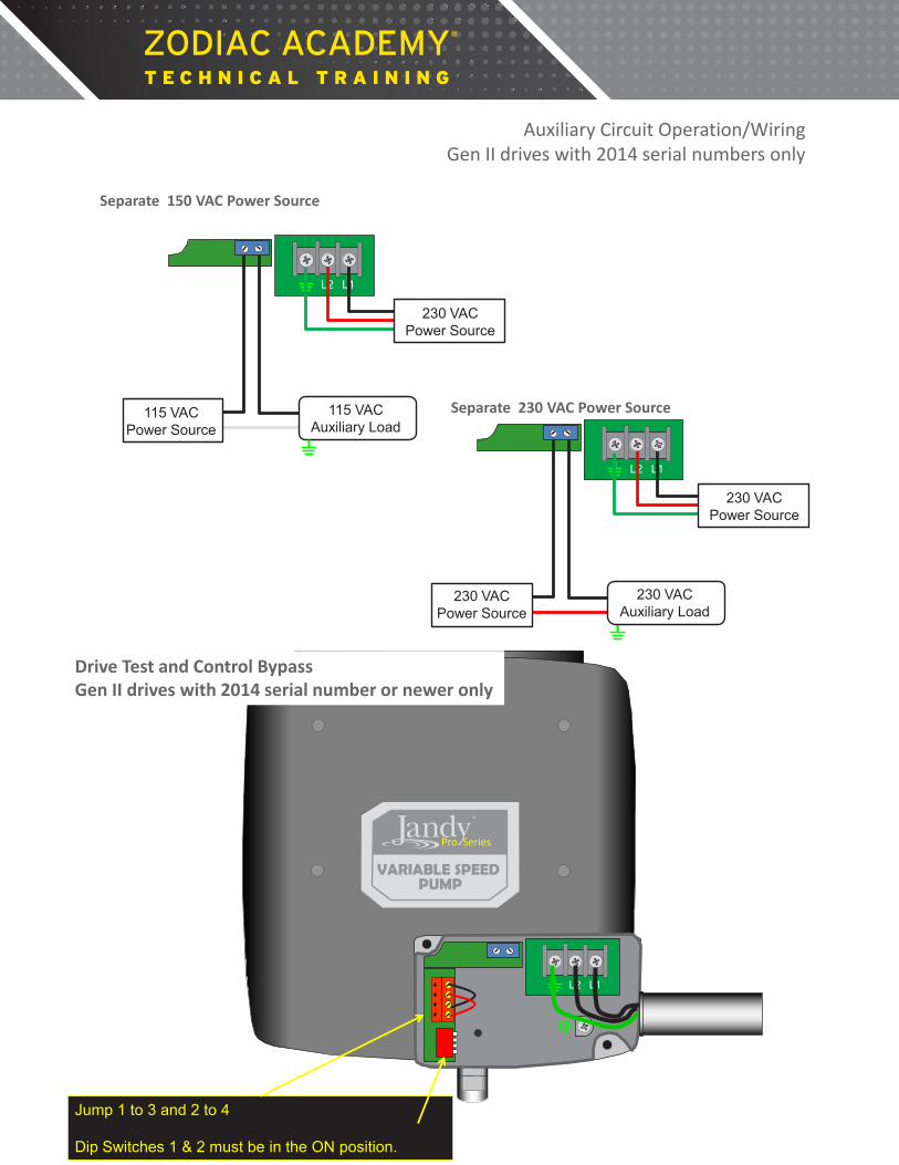
Auxiliary Circuit Operation/Wiring Gen II drives with 2014 serial number or newer only
®
Pro Series
VARIABLE SPEED PUMP
Aux Circuit
Operation of Auxiliary Circuit • Dry contact - single pole, single throw relay. • First time the pump maintains speed above 1725 rpm for 3 + minutes the auxiliary relay closes. • Pump rpm drops below 1725 rpm the auxiliary relay opens. • Pump rpm returns to 1725 or higher relay closes after 5 seconds, not 3 minutes. • Anytime the speed drops below 1725 rpm the relay opens without a delay.
L2 L1
115 VAC Auxiliary Load
115 VAC Power Source
230 VAC Power Source
Separate 150 VAC Power Source
Auxiliary Circuit Operation/Wiring Gen II drives with 2014 serial numbers only
NOTE: The Auxiliary Load relay contact is rated at 11 amps whether wired for 115 or 230 VAC. Please ensure the auxiliary load does not exceed this rating.
L2 L1
230 VAC Power Source
230 VAC Auxiliary Load
Separate 230 VAC Power Source
230 VAC Power Source
L2 L1
®
Pro Series
VARIABLE SPEED PUMP
Jump 1 to 3 and 2 to 4 Dip Switches 1 & 2 must be in the ON position.
Drive Test and Control Bypass Gen II drives with 2014 serial number or newer only

Dip Switch Settings
Variable Speed Controller (JEP-R) Dip Switches 1 and 2 ON
AquaLink RS or PDA Dip Switches 1 and 2 OFF
Pump Address 1 Dip Switches 3 & 4 OFF
Pump Address 2 Dip Switch 3 ON, 4 OFF
Pump Address 3 Dip Switch 3 OFF, 4 ON
Pump Address 4 Dip Switch 3 & 4 ON
ePump™ Gen l ePump Gen ll FloPro™ VSP 1.0
Dip Switch Settings
Do not turn dip switches 1 & 2 ON unless the control panel is a JEP-R VSP Controller. By turning these two switches on, 10 volts DC is sent from the motor to the controller. If these switches are turned on, and the motor is connected to a PDA, AquaLink RS or Z4, the printed circuit board of the control will eventually fail due to 10 volts DC traveling in the wrong direction.
14
Notes:

VSP Programming OneTouch
VSP Programming OneTouch
From the Main Screen highlight MENU/HELP, then press Select.
SELECT
BACK DONE
MENU / HELP
EQUIPMENT ON/OFF
JANDY AquaLinkRS
08/7/07 TUES 9:02 AM
FILTER PUMP OFF AIR 88 °F
ONETOUCH ON/OFF
Select
VSP Setup
Scroll to SYSTEM SETUP and press Select.
SELECT
BACK DONE
MENU
HELP PROGRAM SET TEMP SET TIME DISPLAY LIGHT LOCKOUTS PASSWORD PROGRAM GROUP SYSTEM SETUP
> > > > > > > > >
VSP Setup
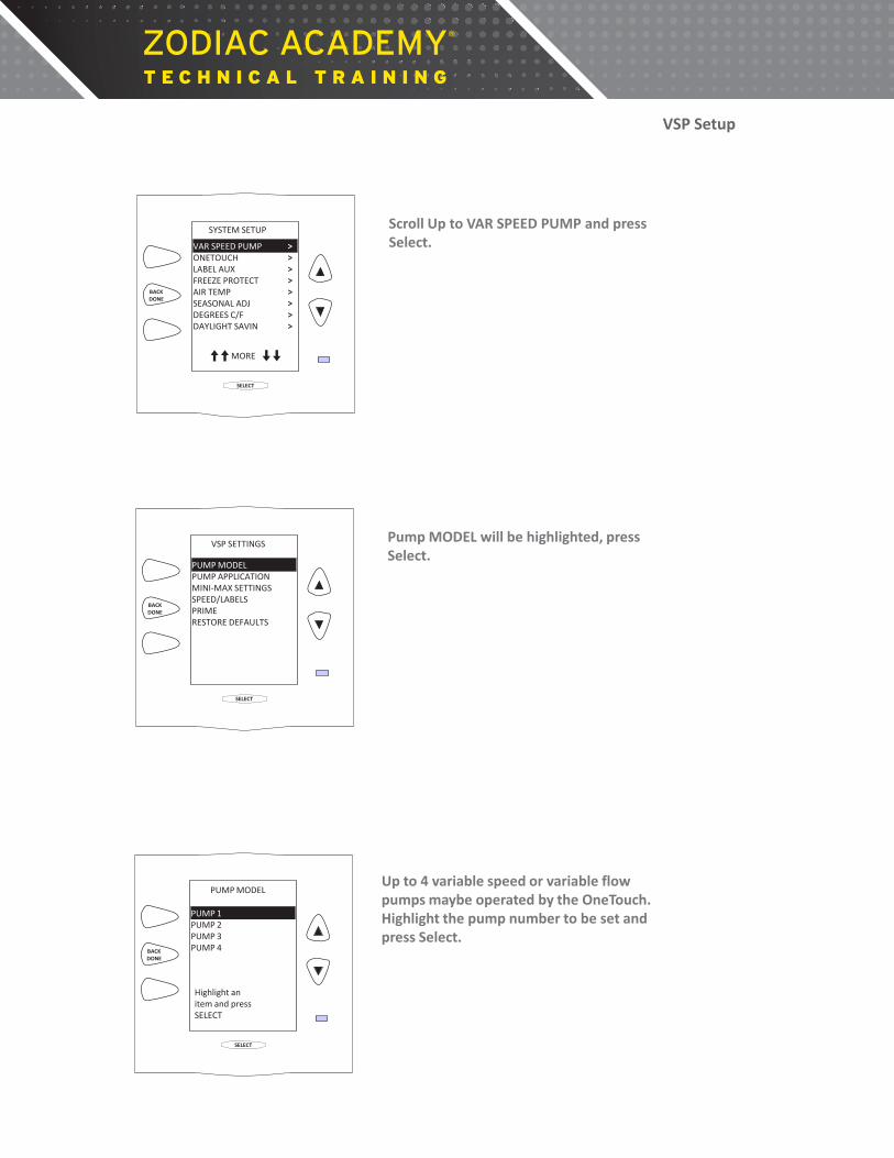
Scroll Up to VAR SPEED PUMP and press Select.
SELECT
BACK DONE
SYSTEM SETUP
VAR SPEED PUMP ONETOUCH LABEL AUX FREEZE PROTECT AIR TEMP SEASONAL ADJ DEGREES C/F DAYLIGHT SAVIN
> > > > > > > > >
MORE
VSP Setup
Pump MODEL will be highlighted, press Select.
SELECT
BACK DONE
VSP SETTINGS
PUMP MODEL PUMP APPLICATION MINI-MAX SETTINGS SPEED/LABELS PRIME RESTORE DEFAULTS
VSP Setup
Up to 4 variable speed or variable flow pumps maybe operated by the OneTouch. Highlight the pump number to be set and press Select.
SELECT
BACK DONE
PUMP MODEL
PUMP 1 PUMP 2 PUMP 3 PUMP 4
Highlight an item and press SELECT
VSP Setup

Highlight the appropriate pump type and press Select. An X will appear to the right of the pump. Press the Back button to return to VSP Settings screen.
Note: Starting with Revision P a OneTouch system can operate any combination of variable speed and variable flow pumps. Note 2: Do not choose VSP AC, this circuit does not operate at this time.
SELECT
BACK DONE
PUMP MODEL PUMP 1
ePUMP Intelliflo VF Intelliflo VS VSP AC
X
Highlight an item and press SELECT
VSP Setup
Highlight PUMP APPLICATION and press Select.
SELECT
BACK DONE
VSP SETTINGS
PUMP MODEL PUMP APPLICATION MINI-MAX SETTINGS SPEED/LABELS PRIME RESTORE DEFAULTS
VSP Setup
Highlight the pump number and press Select.
SELECT
BACK DONE
PUMP MODEL
PUMP 1 PUMP 2 PUMP 3 PUMP 4
Highlight an item and press SELECT
VSP Setup

Highlight where the pump will be used and press Select. Press the Back button to return to VSP Settings screen. Example: Pump application is as a filter pump
SELECT
BACK DONE
FILTRATION AUX. PUMP NOT INSTALLED
PUMP APPLICATION PUMP 1
X
Highlight an item and press SELECT
VSP Setup
Highlight MIN-MAX/SETTINGS and press Select.
SELECT
BACK DONE
VSP SETTINGS
PUMP MODEL PUMP APPLICATION MINI-MAX SETTINGS SPEED/LABELS PRIME RESTORE DEFAULTS
VSP Setup
Highlight the pump number and press Select.
SELECT
BACK DONE
PUMP MODEL
PUMP 1 PUMP 2 PUMP 3 PUMP 4
Highlight an item and press SELECT
VSP Setup

Highlight either MINI LIMIT or MAX LIMIT and press Select. Press the Back button to return to VSP Settings screen.
SELECT
BACK DONE
MNI-MAX SETTINGS PUMP 1
SCALE MIN LIMIT MAX LIMIT
RPM 600
3450
Highlight an item and press SELECT
VSP Setup
Press the Up or Down buttons to change the Speed, press Select when done. Press the Back button to return to VSP Settings screen. Note: Minimum and maximum speeds can be changed in 5 rpm increments. Low minimum limit is set to 600 rpm and the high maximum limit is set to 3450 rpm. To increase speed of change, hold down the Up or Down button for 5 seconds.
SELECT
BACK DONE
MNI-MAX SETTINGS PUMP 1
SCALE MIN LIMIT MAX LIMIT
RPM 600
3450
Highlight an item and press SELECT
VSP Setup
Highlight SPEED/LABELS and press Select. Press the Back button to return to VSP Settings screen.
SELECT
BACK DONE
VSP SETTINGS
PUMP MODEL PUMP APPLICATION MINI-MAX SETTINGS SPEED/LABELS PRIME RESTORE DEFAULTS
VSP Setup

Highlight the pump number and press Select.
SELECT
BACK DONE
PUMP MODEL
PUMP 1 PUMP 2 PUMP 3 PUMP 4
Highlight an item and press SELECT
VSP Setup
Highlight SET SPEEDS and press Select.
SELECT
BACK DONE
SET SPEEDS LABEL SPEEDS ASSIGN SPEEDS
SPEED/LASBELS PUMP 1
Highlight an item and press SELECT
VSP Setup
Because Filtration was chosen earlier as the application, default speeds will be assigned to various circuits. For example, pool filtration default speed is 1750 rpm and spa filtration default speed is 2750 rpm. To change speed for any circuit simply highlight the circuit, press Select then use the Up or Down button to change speed.
SELECT
BACK DONE
SET SPEED (RPM)
POOL SPA SPEED 3 SPEED 4 POOL HEAT SPA HEAT SOLAR HEAT
1750 2750 2750 2750 2250 2250 2750
^^ MORE ^^
VSP Setup

When this screen appears, the first digit in the number will be highlighted. Use the Up or Down buttons to change this digit then press Select. Do the same for the second, third and fourth digits. When the last digit is selected the screen will revert to the previous screen. All four digits must be highlighted and selected for the speed change to be recorded. In this example SPEED 3 has been changed to 2200 rpm. SELECT
BACK DONE
SPEED 3 2200
ADJUST SPEED 3 (RPM)
Use ARROW KEYS to set value. Then SELECT
VSP Setup
Highlight LABEL SPEEDS and press Select.
SELECT
BACK DONE
SET SPEEDS LABEL SPEEDS ASSIGN SPEEDS
SPEED/LASBELS PUMP 1
Highlight an item and press SELECT
VSP Setup
As was the case with SET SPEEDS, since Filtration was chosen earlier as the application, default labels will be assigned to various circuits. For example, pool filtration default label is POOL and spa filtration default label is SPA. To change labels for any circuit simply highlight the circuit and press Select. Note: Names such as POOL, SPA, POOL HEAT, SPA HEAT and SOLAR HEAT cannot be changed.
SELECT
BACK DONE
LABEL SPEEDS
POOL SPA SPEED 3 SPEED 4 POOL HEAT SPA HEAT SOLAR HEAT SPEED 8
> > > > > > > >
VSP Setup

Two choices will appear on the screen, GENERAL LABELS and CUSTOM LABEL. Highlight one, then use the Up and/or Down button to change label or type the custom name. Note: Remember, at this screen the changes to the labels are changes to the speed labels not the auxiliary labels.
SELECT
BACK DONE
LABEL SPEED 3
CURRENT LABEL SPEED 3
GENERAL LABELS CUSTOM LABEL
> >
VSP Setup
In this example SPEED 3 has been changed to FLOOR SYSTEM. When labeling is done press the Back button to return to VSP Settings screen. Note: Remember, at this screen the changes to the labels are changes to the speed labels not the auxiliary labels.
SELECT
BACK DONE
LABEL SPEEDS
POOL SPA FLOOR SYSTEM SPEED 4 POOL HEAT SPA HEAT SOLAR HEAT SPEED 8
> > > > > > > >
VSP Setup
Highlight ASSIGN SPEEDS and press Select.
SELECT
BACK DONE
SET SPEEDS LABEL SPEEDS ASSIGN SPEEDS
SPEED/LASBELS PUMP 1
Highlight an item and press SELECT
VSP Setup
SELECT
BACK DONE
ASSIGN SPEEDS PUMP1
AUX1 AUX2 AUX3 AUX3 AUX4 AUX5 AUX6 AUX7
> > > > > > > >
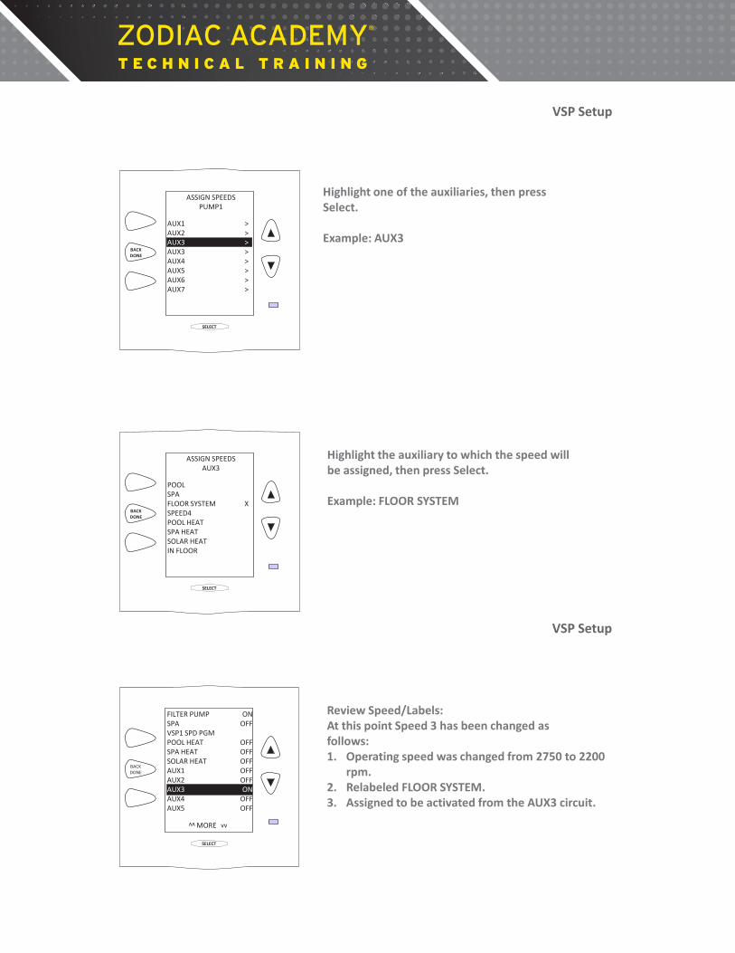
Highlight one of the auxiliaries, then press Select. Example: AUX3
VSP Setup
SELECT
BACK DONE
ASSIGN SPEEDS AUX3
POOL SPA FLOOR SYSTEM SPEED4 POOL HEAT SPA HEAT SOLAR HEAT IN FLOOR
> > X > > > > >
Highlight the auxiliary to which the speed will be assigned, then press Select. Example: FLOOR SYSTEM
VSP Setup
Review Speed/Labels: At this point Speed 3 has been changed as follows: 1. Operating speed was changed from 2750 to 2200
rpm. 2. Relabeled FLOOR SYSTEM. 3. Assigned to be activated from the AUX3 circuit.
SELECT
BACK DONE
FILTER PUMP SPA VSP1 SPD PGM POOL HEAT SPA HEAT SOLAR HEAT AUX1 AUX2 AUX3 AUX4 AUX5
MORE vv
vv
ON OFF
OFF OFF OFF OFF OFF ON
OFF OFF
VSP Setup

Programming This section will cover two ways to change speeds/flow automatically. 1. Program 2. Program Speeds (VSP SPD PGM)
VSP Programming
Start by highlighting MENU / HELP and pressing Select.
SELECT
BACK DONE
MENU / HELP
EQUIPMENT ON/OFF
JANDY AquaLinkRS
08/7/07 TUES 9:02 AM
FILTER PUMP OFF AIR 88 °F
ONETOUCH ON/OFF
Scroll to PROGRAM and press Select.
SELECT
BACK DONE
MENU
HELP PROGRAM SET TEMP SET TIME DISPLAY LIGHT LOCKOUTS PASSWORD PROGRAM GROUP SYSTEM SETUP
> > > > > > > > >
VSP Programming
First way to turn on the pump automatically. Highlight the circuit and press Select. For example: To program the filter pump to turn on automatically highlight FILTER PUMP then press Select. Very Important Note: When changing speeds through programming, always set the speed to be switched to higher than the current programmed speed. Note: The items listed on this screen are the names of some of the circuits that maybe set to turn on and off automatically. To see the other circuits, press the Up or Down Button.
SELECT
BACK DONE
PROGRAM
FILTER PUMP SPA VSP1 SPD PGM POOL HEAT SPA HEAT SOLAR HEAT AUX1 AUX2
MORE vv
vv
VSP Programming
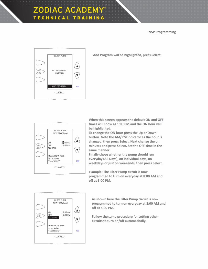
Add Program will be highlighted, press Select.
SELECT
BACK DONE
FILTER PUMP
NO PROGRAMS ENTERED
ADD PROGRAM
VSP Programming
When this screen appears the default ON and OFF times will show as 1:00 PM and the ON hour will be highlighted. To change the ON hour press the Up or Down button. Note the AM/PM indicator as the hour is changed, then press Select. Next change the on minutes and press Select. Set the OFF time in the same manner. Finally chose whether the pump should run everyday (All Days), on individual days, on weekdays or just on weekends, then press Select. Example: The Filter Pump circuit is now programmed to turn on everyday at 8:00 AM and off at 5:00 PM.
SELECT
BACK DONE
FILTER PUMP NEW PROGRAM
Use ARROW KEYS to set value. Then SELECT
1:00 PM 1:00 PM
ON OFF ALL DAYS
VSP Programming
As shown here the Filter Pump circuit is now programmed to turn on everyday at 8:00 AM and off at 5:00 PM. Follow the same procedure for setting other circuits to turn on/off automatically.
SELECT
BACK DONE
FILTER PUMP NEW PROGRAM
Use ARROW KEYS to set value. Then SELECT
8:00 AM 5:00 PM
ON OFF ALL DAYS
VSP Programming
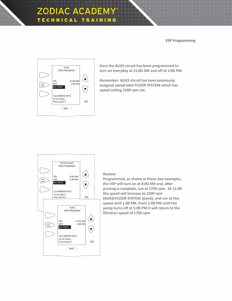
Here the AUX3 circuit has been programmed to turn on everyday at 11:00 AM and off at 1:00 PM. Remember: AUX3 circuit has been previously assigned speed label FLOOR SYSTEM which has speed setting 2200 rpm set.
SELECT
BACK DONE
AUX3 NEW PROGRAM
Use ARROW KEYS to set value. Then SELECT
11:00 AM 1:00 PM
ON OFF ALL DAYS
VSP Programming
Review: Programmed, as shown in these two examples, the VSP will turn on at 8:00 AM and, after priming is complete, run at 1750 rpm. At 11:00 the speed will increase to 2200 rpm (AUX3/FLOOR SYSTEM speed), and run at this speed until 1:00 PM. From 1:00 PM until the pump turns off at 5:00 PM it will return to the filtration speed of 1750 rpm.
SELECT
BACK DONE
FILTER PUMP NEW PROGRAM
Use ARROW KEYS to set value. Then SELECT
8:00 AM 5:00 PM
ON OFF ALL DAYS
SELECT
BACK DONE
AUX3 NEW PROGRAM
Use ARROW KEYS to set value. Then SELECT
11:00 AM 1:00 PM
ON OFF ALL DAYS
VSP Programming
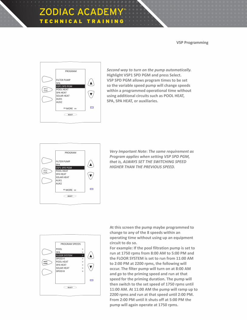
Second way to turn on the pump automatically. Highlight VSP1 SPD PGM and press Select. VSP SPD PGM allows program times to be set so the variable speed pump will change speeds within a programmed operational time without using additional circuits such as POOL HEAT, SPA, SPA HEAT, or auxiliaries.
SELECT
BACK DONE
PROGRAM
FILTER PUMP SPA VSP1 SPD PGM POOL HEAT SPA HEAT SOLAR HEAT AUX1 AUX2
MORE vv
vv
VSP Programming
Very Important Note: The same requirement as Program applies when setting VSP SPD PGM, that is, ALWAYS SET THE SWITCHING SPEED HIGHER THAN THE PREVIOUS SPEED.
SELECT
BACK DONE
PROGRAM
FILTER PUMP SPA VSP1 SPD PGM POOL HEAT SPA HEAT SOLAR HEAT AUX1 AUX2
MORE vv
vv
VSP Programming
At this screen the pump maybe programmed to change to any of the 8 speeds within an operating time without using up an equipment circuit to do so. For example: If the pool filtration pump is set to run at 1750 rpms from 8:00 AM to 5:00 PM and the FLOOR SYSTEM is set to run from 11:00 AM to 2:00 PM at 2200 rpms, the following will occur. The filter pump will turn on at 8:00 AM and go to the priming speed and run at that speed for the priming duration. The pump will then switch to the set speed of 1750 rpms until 11:00 AM. At 11:00 AM the pump will ramp up to 2200 rpms and run at that speed until 2:00 PM. From 2:00 PM until it shuts off at 5:00 PM the pump will again operate at 1750 rpms.
SELECT
BACK DONE
PROGRAM SPEEDS
POOL SPA FLOOR SYSTEM SPEED 4 POOL HEAT SPA HEAT SOLAR HEAT SPEED 8
> > > > > > > >
VSP Programming
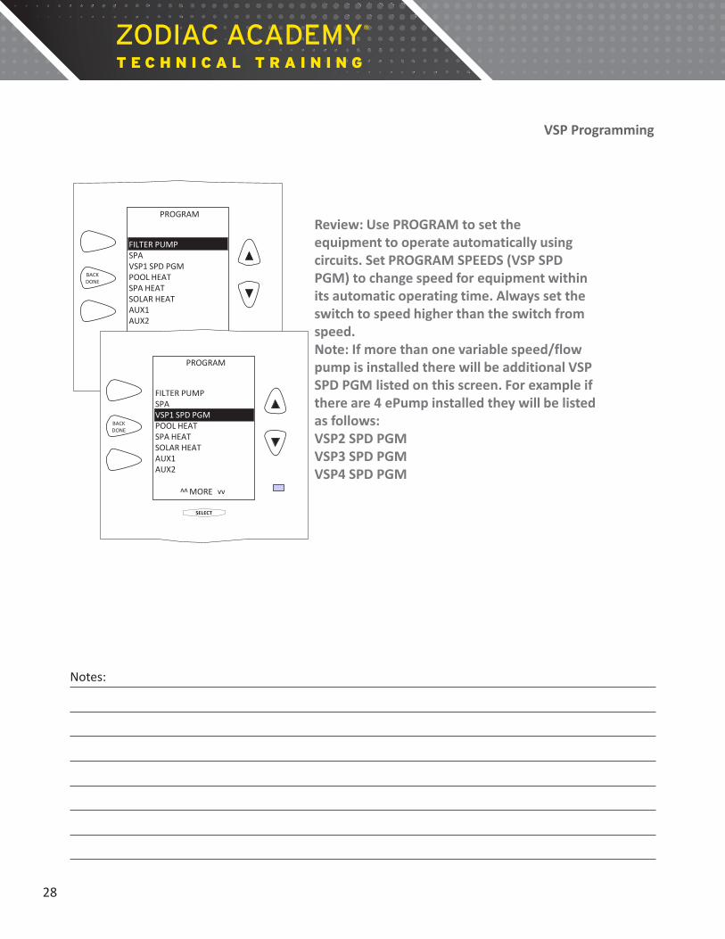
Review: Use PROGRAM to set the equipment to operate automatically using circuits. Set PROGRAM SPEEDS (VSP SPD PGM) to change speed for equipment within its automatic operating time. Always set the switch to speed higher than the switch from speed. Note: If more than one variable speed/flow pump is installed there will be additional VSP SPD PGM listed on this screen. For example if there are 4 ePump installed they will be listed as follows: VSP2 SPD PGM VSP3 SPD PGM VSP4 SPD PGM
SELECT
BACK DONE
PROGRAM
FILTER PUMP SPA VSP1 SPD PGM POOL HEAT SPA HEAT SOLAR HEAT AUX1 AUX2
MORE vv
vv
SELECT
BACK DONE
PROGRAM
FILTER PUMP SPA VSP1 SPD PGM POOL HEAT SPA HEAT SOLAR HEAT AUX1 AUX2
MORE vv
vv
VSP Programming
28
Notes:

Manual Operation This section will cover how to manual turn on and change speeds/flow.
VSP Manual Operation
There are two ways to change speeds Manually, both are selected through the EQUIPMENT ON/OFF screen. To change speeds manually highlight EQUIPMENT ON/OFF from the main screen and press Select.
SELECT
BACK DONE
MENU / HELP
EQUIPMENT ON/OFF
JANDY AquaLinkRS
08/7/07 TUES 9:02 AM
FILTER PUMP OFF AIR 88 °F
ONETOUCH ON/OFF
SELECT
BACK DONE
FILTER PUMP SPA VSP1 SPD ADJ POOL HEAT SPA HEAT SOLAR HEAT AUX1 AUX2 AUX3 AUX4 AUX5
OFF OFF
OFF OFF OFF OFF OFF OFF OFF OFF
^^ MORE ^^
First way to change speeds manually. If a speed has been assigned to a circuit, highlight the circuit and press Select. After priming the pump will go to the speed set to that circuit. Example: AUX1 selected. After priming the pump will run at the speed set to AUX1.
VSP Manual Operation
Second way to change speeds manually. Highlight the circuit for the pump application and press select to turn on this circuit. Example: Pump application is filtration therefore the FILTER PUMP circuit must be turned on first.
SELECT
BACK DONE
FILTER PUMP SPA VSP1 SPD ADJ POOL HEAT SPA HEAT SOLAR HEAT AUX1 AUX2 AUX3 AUX4 AUX5
ON OFF
OFF OFF OFF OFF OFF OFF OFF OFF
^^ MORE ^^
VSP Manual Operation

Scroll to VSP1 SPD ADJ and press Select. Note there maybe more than one VSP SPD ADJ, so chose the appropriate pump.
SELECT
BACK DONE
FILTER PUMP SPA VSP1 SPD ADJ POOL HEAT SPA HEAT SOLAR HEAT AUX1 AUX2 AUX3 AUX4 AUX5
ON OFF
OFF OFF OFF OFF OFF OFF OFF OFF
^^ MORE ^^
VSP Manual Operation
Highlight a speed, then press Select.
SELECT
BACK DONE
SET SPEED (RPM)
POOL SPA FLOOR SYSTEM SPEED 4 POOL HEAT SPA HEAT SOLAR HEAT
1750 2750 2200 2750 2250 2250 2750
^^ MORE ^^ VSP Manual Operation
SELECT
BACK DONE
SPEED4
SET TO 1200 RPM
Use ARROW KEYS To set value. Then SELECT
When this screen appears, the first digit in the number will be highlighted. Use the Up or Down buttons to change this digit then press Select. Do the same for the second, third and fourth digits. When the last digit is selected the screen will revert to the previous screen and the pump will run at the speed selected. All four digits must be highlighted and selected for the speed change to be recorded. In this example SPEED4 has been changed to from 2750 to 1200 rpm.
VSP Manual Operation

When in SERVICE or TIME OUT MODE, the pump will run at the priming speed.
ON
FIL- PMP
AUX 1
AUX 2
AUX 3
AUX 4
AUX 5
AUX 6
AUX 7 SLR-PMP E-HTR INTAKE RETURN CLEANER SOLAR
AUTO
SERVICE
TIME OUT
RESET
HEATER SOLAR
POOL MODE
SPA MODE
SPA DRAIN
SPA FILL
SPARE
ON
SELECT
BACK DONE
SERVICE MODE
NO OPERATIONS ALLOWED HERE
VSP Manual Operation
31
Notes:

Troubleshooting Confirm Compatibility
Troubleshooting
From the main screen highlight MENU / HELP then press Select.
SELECT
BACK DONE
MENU / HELP
EQUIPMENT ON/OFF
JANDY AquaLinkRS
08/7/07 TUES 9:02 AM
FILTER PUMP OFF AIR 88 °F
ONETOUCH ON/OFF
HELP will be highlighted, press Select.
SELECT
BACK DONE
MENU
HELP PROGRAM SET TEMP SET TIME DISPLAY LIGHT LOCKOUTS PASSWORD PROGRAM GROUP SYSTEM SETUP
> > > > > > > > >
Troubleshooting
32
Notes:

Scroll to DIAGNOSTICS and press Select.
SELECT
BACK DONE
HELP
KEYS SERVICE DIAGNOSTIS
> > >
Choose a topic with arrow keys and press SELECT
GO BACK
Troubleshooting
Look for the FIRMWARE number in Diagnostics. The Firmware must be revision O or newer. Example: The revision of this system is R.
SELECT
BACK DONE
MODEL E0260801 TYPE RS-8 Combo FIRMWARE R
WATER AIR SOLAR
SENSORS OK OK OK
NEXT
Troubleshooting
33
Notes:
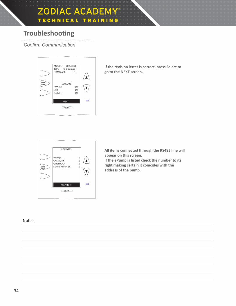
Troubleshooting Confirm Communication
If the revision letter is correct, press Select to go to the NEXT screen.
SELECT
BACK DONE
MODEL E0260801 TYPE RS-8 Combo FIRMWARE R
WATER AIR SOLAR
SENSORS OK OK OK
NEXT
Troubleshooting
All items connected through the RS485 line will appear on this screen. If the ePump is listed check the number to its right making certain it coincides with the address of the pump.
SELECT
BACK DONE
REMOTES
ePump CHEMLINK ONETOUCH SERIAL ADAPTER
CONTINUE
1 1 1 1
Troubleshooting
34
Notes:

Example: Here the ePump is addressed as ePump 2. If this is not the correct address of the ePump the dip switches, located in the junction box at the rear of the ePump, will need to be changed. If the address is correct, press Select to continue.
SELECT
BACK DONE
REMOTES
ePump CHEMLINK ONETOUCH SERIAL ADAPTER
CONTINUE
2 1 1 1
Troubleshooting
At this screen any communication issues with the connection to the RS485 line will be shown. This screen indicates any of the following: 1. The RS485 line (4 conductor wire) is damaged or
not connected properly. 2. Power is off to the motor when it should be on. 3. ePump is damaged.
SELECT
BACK DONE
ERRORS
ePump RS485 ERROR
CONTINUE
1
Troubleshooting
35
Notes:

Affinity Law Up to 90% Annual Energy Savings
Pump Affinity Law
…shows the relationship between volume capacity (gpm), head (pressure or resistance) and power consumption of a pump due to changes in speed (rpm). Holds true for:
Highly efficient permanent magnet motors, such as variable speed pumps.
Does not hold true for:
Standard induction motors, such as single and two speed pumps.
What does this mean?
36
Notes:
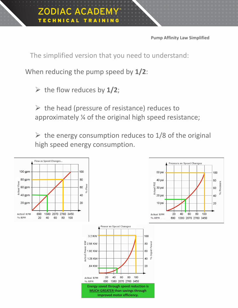
Pump Affinity Law Simplified
The simplified version that you need to understand:
When reducing the pump speed by 1/2: the flow reduces by 1/2;
the head (pressure of resistance) reduces to approximately ¼ of the original high speed resistance;
the energy consumption reduces to 1/8 of the original high speed energy consumption.
Flow as Speed Changes… Pressure as Speed Changes…
Energy saved through speed reduction is MUCH GREATER than savings through
improved motor efficiency.
Flow as Speed Changes…

Pump Affinity Law Example
Jandy ePump installed with 3 inch plumbing, running at a max speed of 3450 rpm, at 140 gpm, and at a head loss is 5.6 ft of head per 100 ft of pipe.
By reducing the speed by half:
3450 1725 140 70 5.6 1.09 12 ¢ 1.5 ¢
Pump Speed: Flow (gpm): Ft of Head: Pump Operating Cost:
1/2
1/2
1/4
1/8
As the flow rate is reduced, you must increase the run time to meet turn over requirements.
850 RPM
30 GPM
High Speed
Low Speed
Half Speed
25% 50% 75% 100% 0%
100 Watt Light Bulb Flow RPM
3450 RPM
1725 RPM
120 GPM
60 GPM
400 W
“PUMP AFFINITY LAW” …indicates the influence on volume capacity (gpm) and
power consumption of a pump due to changes in speed (rpm).
20 Light Bulbs
4 Light Bulbs
% of Speed
One Light Bulb
Power Consumption

LONG TERM COST SAVINGS
As the flow rate is reduced, you must increase the run time to meet turn over requirements.
Pump Operating Cost per/hr:
Pump Operating Daily @ 12 hr/per day: $1.44 $.36
Single VSP
$.12 $.015
Pump Operating Yearly @ 150 days:
Pump Operating Yearly @ 365 days:
$216 $54
$525 $131
Pump Operating 5 Year @ 150 days:
Pump Operating 5 Year @ 365 days:
$1080 $270
$2625 $655
12 HR 24 HR
Jandy® JEP Pump Curve
3"
1½
1½
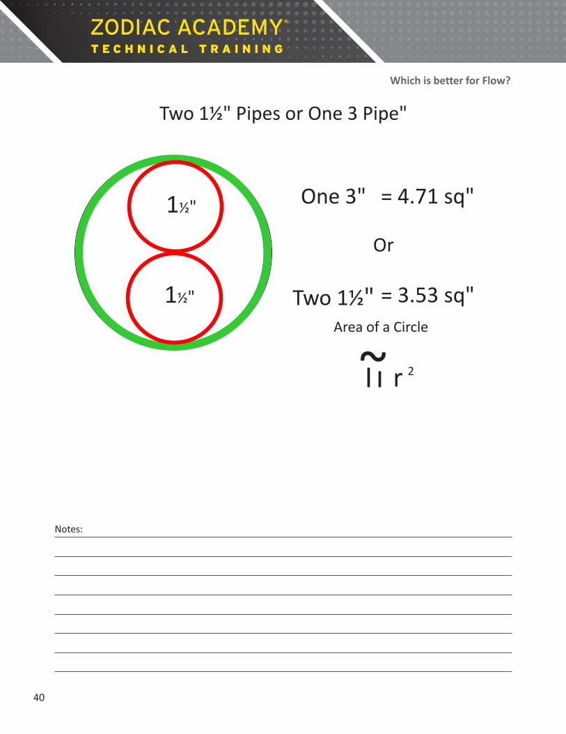
Which is better for Flow?
Two 1½" Pipes or One 3 Pipe"
~ r 2
Area of a Circle
= 3.53 sq"
One 3"
Two 1½"
= 4.71 sq" 1½"
1½"
Or
40
Notes:
•3/4" Pipe •1" Pipe 1 1/4" Pipe 2 1/2" Pipe 3" Pipe •4" Pipe •6" Pipe •U.S. Vel. Loss Vel. Loss Vel. Loss Loss Vel. Loss Vel. Loss •Vel. •Loss •Vel. •Loss •Gals.
Ft. per in Ft. per in Ft. per in in Ft. per in Ft. per in •Ft. per •in •Ft. per •in •per Sec. Feet Sec. Feet Sec. Feet Feet Sec. Feet Sec. Feet •Sec. •Feet •Sec. •Feet •Min.
•1 •0.6 •0.25 •0.37 •0.07 •1 •2 •1.2 •0.9 •0.74 •0.28 •0.43 •0.07 •2 •3 •1.8 •1.92 •1.11 •0.6 •0.64 •0.16 •0.47 •0.07 •3 •4 •2.41 •3.28 •1.48 •1.02 •0.86 •0.25 •0.63 •0.12 •4 •5 •3.01 •5.8 •1.86 •1.52 •1.07 •0.39 •0.79 •0.18 •5 •6 •3.61 •7 •2.33 •2.15 •1.29 •0.55 •0.95 •0.25 •0.57 •0.07 •6 •8 •4.81 •11.8 •2.97 •3.6 •1.72 •0.97 •1.25 •0.46 •0.76 •0.14 •0.54 •0.05 •8
•10 •6.02 •17.9 •3.71 •5.5 •2.15 •1.46 •1.58 •0.69 •0.96 •0.21 •0.67 •0.09 •10 •15 •9.02 •37.8 •5.57 •11.7 •3.22 •3.07 •2.36 •1.45 •1.43 •0.44 •1.01 •0.18 •0.65 •0.07 •15 •20 •7.42 •19.9 •7.29 •4.2 •3.15 •2.47 •1.91 •0.74 •1.34 •0.3 •0.87 •0.12 •20 •25 •9.28 •30 •5.36 •7.9 •3.94 •3.8 •2.39 •1.11 •1.67 •0.46 •1.08 •0.16 •25 •30 •U.S •11.14 •42 •6.43 •11.1 •4.73 •5.2 •2.87 •1.55 •2.01 •0.65 •1.3 •0.23 •30 •35 •GAL. •7.51 •14.7 •5.52 •7 •3.35 •2.06 •2.35 •0.88 •1.52 •0.3 •0.88 •0.07 •35 •40 •PER •8.58 •18.9 •6.3 •8.9 •3.82 •2.63 •2.64 •1.11 •1.73 •0.39 •1.01 •0.09 •40
•MIN. •8" PIPE •9.65 •23.5 •7.09 •11.1 •3.01 •1.39 •1.95 •0.48 •1.13 •0.12 •45 •700 •4.37 •0.66 •10.72 •28.5 •3.35 •1.69 •2.17 •0.58 •1.26 •0.16 •50
•60 •750 •4.7 •0.75 •9.46 •18.9 •5.6 •4.02 •2.36 •2.6 •0.81 •1.51 •0.21 •60 •70 •800 •4.99 •0.82 •11.03 •25.1 •4.69 •3.14 •3.04 •1.09 •1.76 •0.28 •70
•850 •5.37 •0.95 •5.35 •4 •3.47 •1.39 •2.02 •0.37 •80 •90 •900 •5.64 •1.06 •6.03 •5 •3.91 •1.73 •2.27 •0.46 •90
•100 •950 •5.94 •1.23 •9.56 •14.4 •6.7 •6.1 •4.34 •2.1 •2.52 •0.55 •1.11 •0.07 •100 •125 •1000 •6.25 •1.28 •U.S •11.95 •21.8 •8.38 •9.2 •5.42 •3.19 •3.15 •0.85 •1.39 •0.12 •125 •150 •1050 •6.57 •1.4 •GAL. •10.05 •12.8 •6.51 •4.5 •3.78 •1.18 •1.67 •0.16 •150 •175 •1100 •6.89 •1.51 •PER •7.59 •5.9 •4.41 •1.57 •1.94 •0.21 •175 •200 •1150 •7.2 •1.65 •MIN. •10" PIPE •8.68 •7.9 •5.04 •2.08 •2.22 •0.28 •200 •225 •1200 •7.51 •1.79 •1500 •5.99 •0.92 •9.76 •9.4 •5.67 •2.52 •2.5 •0.35 •225 •250 •1250 •7.82 •1.94 •1600 •6.4 •1.03 •10.85 •11.5 •6.3 •3.05 •2.78 •0.42 •250 •275 •1300 •8.13 •2.09 •1700 •6.8 •1.15 •6.93 •3.6 •3.05 •0.48 •275 •300 •1350 •8.45 •2.23 •1800 •7.2 •1.27 •7.56 •4.3 •3.33 •0.58 •300 •325 •1400 •8.77 •2.37 •1900 •7.6 •1.41 •8.19 •5 •3.61 •0.67 •325
•350 •1450 •9.08 •2.53 •2000 •7.99 •1.54 •8.82 •5.7 •3.89 •0.79 •350 •375 •1500 •9.39 •2.68 •2100 •8.39 •1.68 •9.45 •6.5 •4.17 •0.88 •375 •400 •1550 •9.7 •2.85 •2200 •8.8 •1.82 •10.08 •7.3 •4.44 •0.99 •400 •425 •1600 •10 •3.01 •2300 •9.2 •1.99 •4.72 •1.11 •425 •450 •1650 •10.32 •3.21 •2400 •9.6 •2.17 •5 •1.22 •450 •475 •1700 •10.64 •3.4 •2500 •10 •2.34 •5.28 •1.36 •475 •500 •1750 •10.96 •3.59 •2600 •10.4 •2.5 •5.55 •1.5 •500 •550 •1800 •11.27 •3.78 •2700 •10.79 •2.69 •6.11 •1.8 •550 •600 •1850 •11.58 •3.98 •2800 •11.18 •2.88 •6.67 •2.1 •600 •650 •1900 •11.89 •4.19 •2900 •11.59 •3.08 •7.22 •2.44 •650 •700 •1950 •12.21 •4.4 •3000 •11.99 •3.28 •7.78 •3.79 •700 •750 •2000 •12.52 •4.61 •3100 •12.39 •3.32 •8.33 •3.19 •750 •800 •3200 •12.79 •3.35 •8.89 •3.6 •800
Loss in
Feet
•7.88 •50 •13.5
1 1/2" Pipe U.S. Gals.
per Min.
2" Pipe
•4.0 •4.3
•4.78 •5.74 •6.69 •7.4 •7.65
•8.6 •9.5
•11.8 •80
•45 •3.28
Vel. Ft. per
Sec.
Vel. Ft. per
Sec.
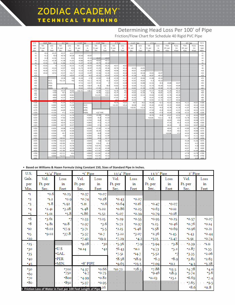
Determining Head Loss Per 100' of Pipe
• Based on Williams & Hazen Formula Using Constant 150, Sizes of Standard Pipe in Inches.
Friction/Flow Chart for Schedule 40 Rigid PVC Pipe
• Friction Loss of Water in Feet per 100 Feet Length of Pipe
Determining Head Loss Per 100' of Pipe
• Based on Williams & Hazen Formula Using Constant 150, Sizes of Standard Pipe in Inches.
Friction/Flow Chart for Schedule 40 Rigid PVC Pipe
• Friction Loss of Water in Feet per 100 Feet Length of Pipe

8.90
Determining Head Loss Per 100' of Pipe
• Based on Williams & Hazen Formula Using Constant 150, Sizes of Standard Pipe in Inches.
Friction/Flow Chart for Schedule 40 Rigid PVC Pipe
• Friction Loss of Water in Feet per 100 Feet Length of Pipe
As an example: At 40 GPM what is the Head Loss in 100 feet of 1.5 inch straight PVC pipe?
2.63
Determining Head Loss Per 100' of Pipe
• Based on Williams & Hazen Formula Using Constant 150, Sizes of Standard Pipe in Inches.
Friction/Flow Chart for Schedule 40 Rigid PVC Pipe
• Friction Loss of Water in Feet per 100 Feet Length of Pipe
Twice the gpm equals four times the resistance!!!
As an example: At 40 GPM what is the Head Loss in 100 feet of 2 inch straight PVC pipe?
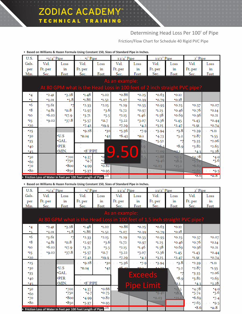
As an example: At 80 GPM what is the Head Loss in 100 feet of 2 inch straight PVC pipe?
9.50
Determining Head Loss Per 100' of Pipe
• Based on Williams & Hazen Formula Using Constant 150, Sizes of Standard Pipe in Inches.
Friction/Flow Chart for Schedule 40 Rigid PVC Pipe
• Friction Loss of Water in Feet per 100 Feet Length of Pipe
Determining Head Loss Per 100' of Pipe
• Based on Williams & Hazen Formula Using Constant 150, Sizes of Standard Pipe in Inches.
Friction/Flow Chart for Schedule 40 Rigid PVC Pipe
• Friction Loss of Water in Feet per 100 Feet Length of Pipe
As an example: At 80 GPM what is the Head Loss in 100 feet of 1.5 inch straight PVC pipe?
Exceeds Pipe Limit
1" 1½" 2" 2½" 3"
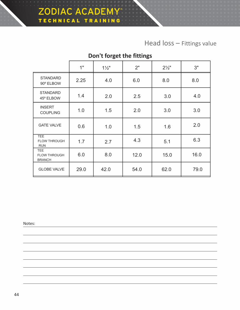
2.25 4.0 6.0 8.0 8.0
1.4 2.0 2.5 3.0 4.0
1.0 1.5 2.0 3.0 3.0
2.0 0.6
1.7
6.0
1.0
2.7
8.0
1.5
4.3
12.0
1.6
5.1
15.0
6.3
16.0
29.0 42.0 54.0 62.0 79.0
STANDARD 90º ELBOW
STANDARD 45º ELBOW
INSERT COUPLING
GATE VALVE
TEE FLOW THROUGH RUN TEE FLOW THROUGH BRANCH
GLOBE VALVE
Head loss – Fittings value
Don't forget the fittings 3 Simple Steps to Variable Speed Success
1. Calculate your 8 hour turn over rate
2. Determine equipment flow minimums
3. Calculate new turnover run time
44
Notes:

3 Simple Steps to Variable Speed Success
1. Calculate your 8 hour turn over rate
2. Determine equipment flow minimums
3. Calculate new turnover run time
45
Notes:

Calculate the pool size in gallons
Length x width x average depth x 7.5 (7.5 = approximate number of gallons in 1 cubic foot of water)
Example: 40' x 20' x 4.8' x 7.5 = 28,800 gallons
40'
20"
Average Depth – 4.8'
Step 1: Calculate the Turnover Rate
The length of time it takes for the circulation system to filter an amount equal to the amount of water in the pool.
Generally one to four turnovers per day (6 to 8 hrs), some local commercial codes are higher.
Gallons # of hrs x 60 = GPM Use 8 hour turnover rate
28,800 gallons
(8 x 60)
= 60 GPM Example:
Step 1: Calculate the Turnover Rate
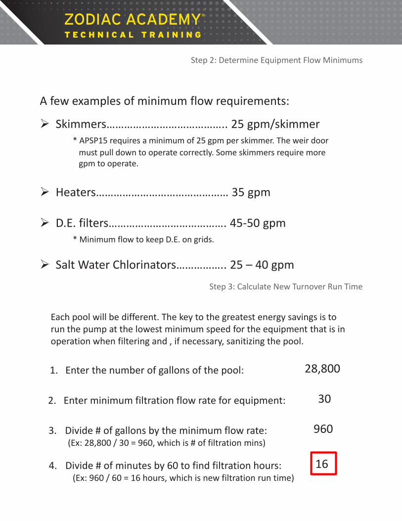
Step 2: Determine Equipment Flow Minimums
A few examples of minimum flow requirements:
Skimmers………………………………….. 25 gpm/skimmer * APSP15 requires a minimum of 25 gpm per skimmer. The weir door must pull down to operate correctly. Some skimmers require more gpm to operate.
Heaters……………………………………… 35 gpm
D.E. filters…………………………………. 45-50 gpm
* Minimum flow to keep D.E. on grids. Salt Water Chlorinators…………….. 25 – 40 gpm
Step 3: Calculate New Turnover Run Time
Each pool will be different. The key to the greatest energy savings is to run the pump at the lowest minimum speed for the equipment that is in operation when filtering and , if necessary, sanitizing the pool.
2. Enter minimum filtration flow rate for equipment: 30
1. Enter the number of gallons of the pool: 28,800
3. Divide # of gallons by the minimum flow rate: (Ex: 28,800 / 30 = 960, which is # of filtration mins)
960
4. Divide # of minutes by 60 to find filtration hours: (Ex: 960 / 60 = 16 hours, which is new filtration run time)
16

Vacuum x 1.13 = Suction head Pressure x 2.31 = Discharge head Added together equals Total Dynamic Head
Vacuum
PSI
Calculate the existing Feet of Head
Vacuum = 10 Pressure = 9
(Vacuum) 10 x 1.13 = 11.30 (Pressure) 9 x 2.31 = 20.79 Total head in system = 32.09
Calculate the existing Feet of Head

Notes:
