jp25410r99 utran lu interface general aspects and principles
TRANSCRIPT

JP 3GA 25.410(R99)
UTRAN Iu Interface:General Aspects and Principles
Version 2
October 25, 2000
THE TELECOMMUNICATION TECHNOLOGY COMMITTEE

i JP-3GA-25.410(R99)
JP-3GA-25.410(R99)UTRAN Iu Interface: General Aspects and Principles
Remarks
1.Application level of English descriptionApplication level:E3
English description is included in the text and figures of main body, annexes and appendices.
2.Relationship with international recommendations and standardsThis standard is standardized based on the Technical Specification 25.410(Version 3.2.0) approved by 3GPP in
June 2000.
3.Departures from international recommendations3.1 Selection of optional items
None
3.2 Items of national matter
None
3.3 Changes to original standard
(1) Standards referred to in the original standard, which are replaced by TTC/ARIB standards.
Refer to Table 1.
(2) Items added to the original standard
None
(3) Items deleted from the original standard
None
(4) Items changed from the original standard
None
3.4 Difference in chapter ordering from the original standard.
There is no difference in chapter ordering from the original standard.
4.Change history
Revision Date Contents
V.1 Mar.31,2000 Newly standardized
V.2 Oct.25,2000 Revised based on the Technical Specification 25.410
(Version 3.2.0) approved by 3GPP
5.IPRThere is no specific description about IPR in this standard.
6.OthersNone

ii JP-3GA-25.410(R99)
Table 1 Replaced standards referred
original standard replacement
ITU-T RECOMMENDATION Q.711
Title : Functional description of the Signalling
Connection Control Part
TTC STANDARDS JT-Q711
Title : Functional description of the Signalling
Connection Control Part
Note:
Contents indicated with # (indicating supplementary
information to help understanding) in JT-Q711, and
simultaneously related to following descriptions, shall be
considered part of formal JT-Q711 specification. The
related descriptions are, SCCP connection oriented
services, and descriptions related to SCCP functions
which are based on MTP conforming to JT-Q2210.
For descriptions related to SCCP connection oriented
services, following sections in TTC standard shall be
replaced with corresponding sections in ITU
recommendation according to following table.
TTC ITU Contents
2.1 6.1 Connection Oriented Services
4.1 8.1 Connection Oriented Functions
ITU-T RECOMMENDATION Q.712
Title : Definition and function of signalling connection
control part messages
TTC STANDARDS JT-Q712
Title : Definition and function of signalling connection
control part messages
Note:
Contents indicated with # (indicating supplementary
information to help understanding) in JT-Q712, and
simultaneously related to following descriptions, shall be
considered part of formal JT-Q712 specification. The
related descriptions are, SCCP connection oriented
services, and descriptions related to SCCP functions
which are based on MTP conforming to JT-Q2210.
For descriptions related to SCCP connection oriented
services, following sections in TTC standard shall be
replaced with corresponding sections in ITU
recommendation according to following table.
TTC ITU Contents
1.1 1.1 connection confirm (CC)
1.2 1.2 connection request (CR)
1.3 1.3 connection refused(CR)
1.4 1.4 data acknowledgement(AK)
1.5 1.5 data form 1(DT1)

iii JP-3GA-25.410(R99)
1.6 1.6 data form 2(DT2)
1.7 1.7 expedited data(ED)
1.8 1.8 expedited data acknowledgement(EA)
1.9 1.9 inactivity test(IT)
1.10 1.10 protocol data unit error(ERR)
1.11 1.11 released(RLSD)
1.12 1.12 release complete(RLC)
1.13 1.13 reset confirm(RSC)
1.14 1.14 reset request(RSR)
2.4 2.4 credit
2.6 2.6 diagnostic
2.7 2.7 error cause
2.9 2.9 local reference number(source/destination)
2.11 2.11 receive sequence number
2.12 2.12 refusal cause
2.13 2.13 release cause
2.14 2.14 reset cause
2.16 2.16 segmenting/reassembling
2.17 2.17 sequencing/segmenting
For descriptions related to SCCP functions which are
based on MTP conforming to JT-Q2210, following
sections in TTC standard shall be replaced with
corresponding sections in ITU recommendation according
to following table.
TTC ITU Contents
1.25 1.25 long unitdata (LUDT)
1.26 1.26 long unit data service(LUDTS)
2.23 2.23 long data
ITU-T RECOMMENDATION Q.713
Title : Signalling Connection Control Part formats and
codes
TTC STANDARDS JT-Q713
Title : Signalling Connection Control Part formats and
codes
Note:
Contents indicated with # (indicating supplementary
information to help understanding) in JT-Q713, and
simultaneously related to following descriptions, shall be
considered part of formal JT-Q713 specification. The
related descriptions are, SCCP connection oriented
services, and descriptions related to SCCP functions
which are based on MTP conforming to JT-Q2210.
For descriptions related to SCCP connection oriented
services, following sections in TTC standard shall be
replaced with corresponding sections in ITU

iv JP-3GA-25.410(R99)
recommendation according to following table.
TTC ITU Contents
3.2 3.2 Destination local reference
3.3 3.3 Source local reference
3.7 3.7 Segmenting/reassembling
3.8 3.8 Receive sequence number
3.9 3.9 Sequencing/segmenting
3.10 3.10 Credit
3.11 3.11 Release cause
3.13 3.13 Reset cause
3.14 3.14 Error cause
3.15 3.15 Refusal cause
4.2 4.2 Connection request(CR)
4.3 4.3 Connection confirm(CC)
4.4 4.4 Connection refused(CREF)
4.5 4.5 Released(RLSD)
4.6 4.6 Release complete(RLC)
4.7 4.7 Data form 1(DT1)
4.8 4.8 Data form 2(DT2)
4.9 4.9 Data acknowledgement(AK)
4.12 4.12 Expedited data(ED)
4.13 4.13 Expedited data acknowledgement(EA)
4.14 4.14 Reset request(RSR)
4.15 4.15 Reset confirm(RSC)
4.16 4.16 Protocol data unit error(ERR)
4.17 4.17 Inactivity test(IT)
For descriptions related to SCCP functions which are
based on MTP conforming to JT-Q2210, following
sections in TTC standard shall be replaced with
corresponding sections in ITU recommendation according
to following table.
TTC ITU Contents
3.20 3.20 Long data
4.20 4.20 Long unitdata(LUDT)
4.21 4.21 Long unitdata service(LUDTS)
ITU-T RECOMMENDATION Q.714
Title : Signalling connection control part procedures
TTC STANDARDS JT-Q714
Title : Signalling connection control part procedures
Note:
Contents indicated with # (indicating supplementary
information to help understanding) in JT-Q714, and
simultaneously related to following descriptions, shall be
considered part of formal JT-Q714 specification. The
related descriptions are, SCCP connection oriented

v JP-3GA-25.410(R99)
services, and descriptions related to SCCP functions
which are based on MTP conforming to JT-Q2210.
For descriptions related to SCCP connection oriented
services, following sections in TTC standard shall be
replaced with corresponding sections in ITU
recommendation according to following table.
TTC ITU Contents
1.1 1.1 general characteristics of SCCP
1.2 1.2 procedures for connection-oriented services
2.5 2.5 compatibility test
2.6 2.6 traffic limitation mechanism
3. 3. connection-oriented procedures
4.1 4.1 data transfer
5. 5. SCCP management procedures
3G TS25.401
Title : UTRAN Overall Description
ARIB STANDARDS ARIB STD-T63-25.401
Title : IMT-2000 DS-CDMA System UTRAN Overall
Description
3G TS 23.003
Title : Numbering, Addressing and Identification
TTC STANDARDS JP-3GA-23.003(R99)
Title : Numbering, Addressing and Identification
3G TS23.930
Title : Iu Principles
TTC STANDARDS JP-3GA-23.930(R99)
Title : Iu Principles
3G TS23.110
Title : UMTS Access Stratum; Services and Functions
TTC STANDARDS JP-3GA-23.110(R99)
Title : UMTS Access Stratum; Services and Functions
3G TS25.411
Title : UTRAN Iu Interface Layer 1
TTC STANDARDS JP-3GA-25.411(R99)
Title : UTRAN Iu Interface Layer 1
3G TS25.412
Title : UTRAN Iu Interface Signalling Transport
TTC STANDARDS JP-3GA-25.412(R99)
Title : UTRAN Iu Interface Signalling Transport
3G TS25.413
Title : UTRAN Iu Interface RANAP Signalling
TTC STANDARDS JP-3GA-25.413(R99)
Title : UTRAN Iu Interface RANAP Signalling
3G TS25.414
Title : UTRAN Iu Interface Data Transport and
Transport Signalling
TTC STANDARDS JP-3GA-25.414(R99)
Title : UTRAN Iu Interface Data Transport and Transport
Signalling
3G TS25.415
Title : UTRAN Iu Interface User Plane Protocols
TTC STANDARDS JP-3GA-25.415(R99)
Title : UTRAN Iu Interface User Plane Protocols
3G TS25.419
Title : UTRAN Iu Interface: Service Area Broadcast
Protocol SABP
TTC STANDARDS JP-3GA-25.419(R99)
Title : UTRAN Iu Interface Service Area Broadcast
Protocol SABP
3G TS 25.410 V3.2.0 (2000-03)Technical Specification
3rd Generation Partnership Project;Technical Specification Group Radio Access Network;
UTRAN Iu Interface: General Aspects and Principles(Release 1999)
The present document has been developed within the 3rd Generation Partnership Project (3GPP TM) and may be further elaborated for the purposes of 3GPP.
The present document has not been subject to any approval process by the 3GPP Organisational Partners and shall not be implemented.This Specification is provided for future development work within 3GPP only. The Organisational Partners accept no liability for any use of this SpecificatioSpecifications and reports for implementation of the 3GPP TM system should be obtained via the 3GPP Organisational Partners' Publications Offices.

3GPP
2 3G TS 25.410 V3.2.0 (2000-03)3G TS 25.410 V3.2.0
Keywords
3GPP
Postal address
3GPP support office address650 Route des Lucioles - Sophia Antipolis
Valbonne - FRANCETel.: +33 4 92 94 42 00 Fax: +33 4 93 65 47 16
Internethttp://www.3gpp.org
Copyright Notification
No part may be reproduced except as authorized by written permission.The copyright and the foregoing restriction extend to reproduction in all media.
© 2000, 3GPP Organizational Partners (ARIB, CWTS, ETSI, T1, TTA,TTC).All rights reserved.

3GPP
3 3G TS 25.410 V3.2.0 (2000-03)3G TS 25.410 V3.2.0
ContentsForeword ............................................................................................................................................................5
1 Scope........................................................................................................................................................6
2 References................................................................................................................................................6
3 Definitions and abbreviations ..................................................................................................................63.1 Definitions ............................................................................................................................................................... 63.2 Abbreviations .......................................................................................................................................................... 7
4 General Aspects .......................................................................................................................................84.1 UTRAN Architecture .............................................................................................................................................. 84.1.1 Iu Interface Architecture .................................................................................................................................... 84.1.2 Iu connection principles...................................................................................................................................... 94.2 Iu Interface General Principles................................................................................................................................. 94.3 Iu Interface Specification Objectives ....................................................................................................................... 94.4 Iu Interface Capabilities ........................................................................................................................................... 94.5 Iu Interface Characteristics..................................................................................................................................... 104.5.1 Use of Transport Network User Plane as Signalling Bearer ............................................................................ 104.5.1.1 Use of SCCP .................................................................................................................................................... 104.5.1.1.1 General ....................................................................................................................................................... 104.5.1.1.2 SCCP connection establishment................................................................................................................. 114.5.1.1.3 SCCP connection release ........................................................................................................................... 124.5.1.1.4 General SCCP Abnormal Conditions ......................................................................................................... 124.5.2 Use of Transport Network User Plane as User Data Bearer ............................................................................ 134.5.2.1 Use of AAL2.................................................................................................................................................... 134.5.2.2 Use of GTP-U.................................................................................................................................................. 134.5.3 Use of Transport Network User Plane on Iu-BC ............................................................................................. 13
5 Functions of the Iu Interface Protocols & Functional Split ....................................................................135.1 General .................................................................................................................................................................. 135.2 RAB management Functions ................................................................................................................................. 145.2.1 RAB establishment, modification and release function ................................................................................... 145.2.2 RAB characteristics mapping to Uu bearers function ...................................................................................... 155.2.3 RAB characteristics mapping to Iu transport bearers....................................................................................... 155.2.4 RAB queuing, pre-emption and priority function ............................................................................................ 155.3 Radio Resource Management over Iu.................................................................................................................... 155.3.1 Radio resource admission control .................................................................................................................... 155.3.2 Broadcast information management................................................................................................................. 165.4 Iu link Management functions................................................................................................................................ 165.4.1 Iu Signalling Link Management function ......................................................................................................... 165.4.2 ATM Virtual Connection Management function ............................................................................................. 165.4.3 AAL2 connection establish and release function ............................................................................................. 165.4.4 AAL5 management function ............................................................................................................................ 165.4.5 GTP-U tunnels management function.............................................................................................................. 165.4.6 TCP Management Function ............................................................................................................................. 165.4.7 Buffer Management ......................................................................................................................................... 175.5 Iu U-plane (RNL)Management Functions.............................................................................................................. 175.5.1 Iu U-plane frame protocol mode selection function ......................................................................................... 175.5.2 Iu U-plane frame protocol initialisation............................................................................................................ 175.6 Mobility Management Functions........................................................................................................................... 175.6.1 Location information update function.............................................................................................................. 175.6.2 Handover and Relocation functions ................................................................................................................. 175.6.2.1 Inter RNC hard HO function, Iur not used or not available ............................................................................. 175.6.2.2 Serving RNS Relocation function.................................................................................................................... 175.6.2.3 Inter system Handover (e.g. GSM-UMTS) function........................................................................................ 175.6.3 Paging Triggering ............................................................................................................................................ 185.7 Security Functions ................................................................................................................................................. 18
3GPP
4 3G TS 25.410 V3.2.0 (2000-03)3G TS 25.410 V3.2.0
5.7.1 Data Confidentiality......................................................................................................................................... 185.7.1.1 Radio interface ciphering function................................................................................................................... 185.7.1.2 Ciphering key management function................................................................................................................ 185.7.2 Data integrity ................................................................................................................................................... 185.7.2.1 Integrity checking ............................................................................................................................................ 185.7.2.2 Integrity key management ................................................................................................................................ 185.8 Service and Network Access Functions................................................................................................................. 185.8.1 Core Network signalling data transfer function ............................................................................................... 185.8.2 Data Volume Reporting ................................................................................................................................... 185.8.3 UE Tracing ...................................................................................................................................................... 185.8.4 Location reporting function ............................................................................................................................. 185.9 Co-ordination Functions ........................................................................................................................................ 195.9.1 Paging Co-ordination function......................................................................................................................... 19
6 Iu Interface Protocol Structure................................................................................................................196.1 General .................................................................................................................................................................. 196.2 Iu-CS ..................................................................................................................................................................... 196.3 Iu-BC...................................................................................................................................................................... 206.4 Iu-PS ...................................................................................................................................................................... 21
7 Other Iu Interface Specifications ............................................................................................................227.1 UTRAN Iu Interface: Layer 1 (UMTS 25.411)...................................................................................................... 227.2 UTRAN Iu Interface: Signalling Transport (UMTS 25.412) ................................................................................. 227.3 UTRAN Iu Interface: RANAP Specification (UMTS 25.413) .............................................................................. 227.4 UTRAN Iu Interface: Data Transport and Transport Signalling (UMTS 25.414) ................................................. 227.5 UTRAN Iu Interface: CN-UTRAN User Plane Protocol (UMTS 25.415) ............................................................ 237.6 UTRAN Iu Interface: Service Area Broadcast Protocol SABP (UMTS 25.419)................................................... 237.7 Summary................................................................................................................................................................ 23
Annex A (informative): Change history ...............................................................................................24
History..............................................................................................................................................................25

3GPP
5 3G TS 25.410 V3.2.0 (2000-03)3G TS 25.410 V3.2.0
ForewordThis Technical Specification (TS) has been produced by the 3rd Generation Partnership Project (3GPP).
The contents of the present document are subject to continuing work within the TSG and may change following formalTSG approval. Should the TSG modify the contents of the present document, it will be re-released by the TSG with anidentifying change of release date and an increase in version number as follows:
Version x.y.z
where:
x the first digit:
1 presented to TSG for information;
2 presented to TSG for approval;
3 or greater indicates TSG approved document under change control.
y the second digit is incremented for all changes of substance, i.e. technical enhancements, corrections, updates,etc.
z the third digit is incremented when editorial only changes have been incorporated in the document.

3GPP
6 3G TS 25.410 V3.2.0 (2000-03)3G TS 25.410 V3.2.0
1 ScopeThe present document is an introduction to the UMTS 25.41x series of Technical Specifications that define the Iuinterface for the interconnection of Radio Network Controller (RNC) component of the UMTS Terrestrial Radio AccessNetwork (UTRAN) to the Core Network of the UMTS system.
2 ReferencesThe following documents contain provisions which, through reference in this text, constitute provisions of the presentdocument.
• References are either specific (identified by date of publication, edition number, version number, etc.) ornon-specific.
• For a specific reference, subsequent revisions do not apply.
• For a non-specific reference, the latest version applies.
• For this Release 1999 document, references to 3G documents are for Release 1999 versions (version 3.x.y).
[1] UMTS 25.401: "UTRAN Overall Description".
[2] UMTS 23.930: "Iu Principles".
[3] UMTS 23.110: "UMTS Access Stratum; Services and Functions".
[4] UMTS 25.411: "UTRAN Iu Interface: Layer 1".
[5] UMTS 25.412: "UTRAN Iu Interface: Signalling Transport".
[6] UMTS 25.413: "UTRAN Iu Interface: RANAP Signalling".
[7] UMTS 25.414: "UTRAN Iu Interface: Data Transport & Transport Signalling"
[8] UMTS 25.415: "UTRAN Iu Interface: CN-RAN User Plane Protocol".
[9] ITU-T Recommendation Q.711 (7/96): "Functional description of the signalling connection controlpart".
[10] ITU-T Recommendation Q.712 (7/96): "Definition and function of signalling connection controlpart messages".
[11] ITU-T Recommendation Q.713 (7/96): "Signalling connection control part formats and codes".
[12] ITU-T Recommendation Q.714 (7/96): "Signalling connection control part procedures".
[13] UMTS 23.003: "Numbering, Addressing and Identification".
[14] UMTS 25.419: "UTRAN Iu Interface: Service Area Broadcast Protocol SABP".
[15] UMTS 23.110: "UMTS Access Stratum; Services and Functions".
3 Definitions and abbreviations
3.1 DefinitionsFor the purposes of the present document, the terms and definitions given in [1] apply.

3GPP
7 3G TS 25.410 V3.2.0 (2000-03)3G TS 25.410 V3.2.0
3.2 AbbreviationsFor the purposes of the present document, the following abbreviations apply:
3G-MSC 3rd Generation Mobile Switching Centre3G-SGSN 3rd Generation Serving GPRS Support NodeAAL ATM Adaptation LayerATM Asynchronous Transfer ModeBC BroadcastBSSMAP Base Station Subsystem Management Application PartCBS Cell Broadcast ServiceCC Connection ConfirmCN Core NetworkCR Connection ReleaseCREF Connection RefusalCS Circuit SwitchedGT Global TitleGTP-U GPRS Tunnelling ProtocolIMSI International Mobile Subscriber IdentityIP Internet ProtocolISDN Integrated Services Digital NetworkLA Location AreaNAS Non Access StratumO&M Operation and MaintenancePS Packet SwitchedPSTN Public Switched Telephone NetworkPVC Permanent Virtual CircuitQoS Quality of ServiceRA Routing AreaRAB Radio Access BearerRANAP Radio Access Network Application PartRLP Radio Link ProtocolRNC Radio Network ControllerRNL Radio Network LayerRRC Radio Resource ControlSA Service AreaSABP Service Area Broadcast ProtocolSAP Service Access PointSCCP Signalling Connection Control PartSPC Signalling Point CodeSRNS Serving Radio Network SubsystemSSN Sub-System NumberSVC Switched Virtual CircuitTCP Transmission Control ProtocolUE User EquipmentUDP User Datagram ProtocolUP User PlaneURA UTRAN Registration AreaUTRAN UMTS Terrestrial Radio Access NetworkVC Virtual Circuit

3GPP
8 3G TS 25.410 V3.2.0 (2000-03)3G TS 25.410 V3.2.0
4 General Aspects
4.1 UTRAN Architecture
4.1.1 Iu Interface ArchitectureThe overall UMTS architecture and UTRAN architectures are described in [1]. This subclause specifies only thearchitecture of the Iu interface, and shall not constrain the network architecture of either Core or Radio AccessNetworks.
The Iu interface is specified at the boundary between the Core Network and UTRAN. Figure 4.1 depicts the logicaldivision of the Iu interface. From the Iu perspective, the UTRAN access point is an RNC.
Core Network (CN)UTRAN
Node B
Node B
Node B
Node B
RNC
Iu Interface
�Iu-BC�
�Iu-CS�
BCDomain
CSDomain
PSDomain
�Iu-PS�
RNC
Figure 4.1: Iu Interface Architecture
The Iu interface towards the PS-domain of the core network is called Iu-PS, and the Iu interface towards the CS-domainis called Iu-CS. The differences between Iu-CS and Iu-PS are treated elsewhere in this specification. The Iu interface tothe Broadcast domain is called Iu-BC.
There shall not be more than one Iu interface (Iu-CS) towards the CS domain and one Iu interface (Iu-PS) towards thePS-domain from any one RNC. There may be multiple Iu interfaces (Iu-BC) from an RNC towards the Broadcastdomain.
In the separated core network architecture, this means that there shall be separate signalling and user data connectionstowards the PS and CS domains � this applies in both transport and radio network layers.
In the combined architecture, there shall be separate connections in the user plane towards the PS and CS domains (inboth transport and radio network layers). In the control plane, there shall be separate SCCP connections to the twological domains.
In either architecture, there can be several RNCs within UTRAN and so UTRAN may have several Iu access pointstowards the Core Network. As a minimum, each Iu access point (in UTRAN or CN) shall independently fulfil therequirements of the relevant Iu specifications (25.41x series � see clause 7).

3GPP
9 3G TS 25.410 V3.2.0 (2000-03)3G TS 25.410 V3.2.0
4.1.2 Iu connection principlesThe Iu interface has a hierarchical architecture where one higher layer entity controls several lower layer entities. Thehierarchy for the CN - UTRAN signalling connection end points is described below:
- Each CN Access Point may be connected to one or more UTRAN Access Points.
- For the PS and CS domains, each UTRAN Access Point shall not be connected to more than one CN AccessPoint per CN domain.
- For the BC domain, each UTRAN Access Point may be connected to one or more CN Access Points.
4.2 Iu Interface General PrinciplesFrom a UTRAN perspective, maximising the commonality of the various protocols that flow on the Iu interface isdesirable. This means at the minimum that:
- A common set of radio access bearer services will be offered by UTRAN to the Core Network nodes, regardlessof their type (e.g. 3G-MSC or 3G-SGSN).
There will be a common functional split between UTRAN and the Core Network nodes, regardless of their type(e.g. 3G-MSC or 3G-SGSN).
Signalling in the radio network control plane shall not depend on the specific choice of transport layers.
4.3 Iu Interface Specification ObjectivesThe following objectives are partly derived from [2].
The Iu interface shall be specified such that it can support:
- the interconnection of RNCs with Core Network Access Points within a single PLMN.
- the interconnection of RNCs with Core Network Access Points irrespective of the manufacturer of any of theelements.
- all UMTS services.
The Iu interface shall facilitate the use of the same RNC, MSC or SGSN in all PLMNs.
The Iu interface shall facilitate the sharing of transport technology between Iu-PS and Iu-BC.
The Iu interface shall allow interworking to the GSM Core Network.
Independence between the protocol layers and between control and user planes shall be maintained on the Iu interface.
The Iu interface shall allow independent evolution of technologies within the Core, Radio Access and TransportNetworks.
The Iu interface shall allow separate evolution of O&M facilities.
The Iu interface shall be standardised as an open and multi-vendor interface.
The Iu interface specifications shall facilitate the migration of some services from the CS-domain to the PS-domain. Inparticular, the RANAP protocol shall be common to both PS and CS domains, and the Iu user plane protocol(s) shall beindependent of the core network domain (PS or CS), except where a specific feature is only required for one domain.
4.4 Iu Interface CapabilitiesThe following capabilites are derived from the requirements described in [2].
The Iu interface supports:

3GPP
10 3G TS 25.410 V3.2.0 (2000-03)3G TS 25.410 V3.2.0
- procedures to establish, maintain and release Radio Access Bearers;
- procedures to perform intra-system handover, inter-system handover and SRNS relocation;
- procedures to support the Cell Broadcast service;
- a set of general procedures, not related to a specific UE;
- the separation of each UE on the protocol level for user specific signalling management;
- the transfer of NAS signalling messages between UE and CN;
- location services by transferring requests from the CN to UTRAN, and location information from UTRAN toCN. The location information may comprise a geographical area identifier or global co-ordinates with uncertaintyparameters;
- simultaneous access to multiple CN domains for a single UE;
- mechanisms for resource reservation for packet data streams.
4.5 Iu Interface Characteristics
4.5.1 Use of Transport Network User Plane as Signalling Bearer
4.5.1.1 Use of SCCP
4.5.1.1.1 General
The SCCP is used to support signalling messages between the CNs and the RNC. One user function of the SCCP, calledRadio Access Network Application Part (RANAP), is defined. The RANAP uses one signalling connection per activeUE and CN for the transfer of layer 3 messages.
Both connectionless and connection-oriented procedures are used to support the RANAP. TS 25.413 explains whetherconnection oriented or connectionless services should be used for each layer 3 procedure.
RANAP may use SSN, SPC and/or GT and any combination of them as addressing schemes for the SCCP. Which of theavailable addressing scheme to use for the SCCP is an operator matter.
When GT addressing is utilised, the following settings shall be used:
- SSN Indicator = 1 (RANAP SSN as defined in [13] shall always be included).
- Global Title Indicator = 0100 (GT includes translation type, numbering plan, encoding scheme and nature ofaddress indicator).
- Translation Type = 0000 0000 (not used).
- Numbering Plan = 0001 (E.163/4).
- Nature of Address Indicator = 000 0100 (International Significant Number).
- Encoding Scheme = 0001 or 0010 (BCD, odd or even).
- Routing indicator = 0 or 1 (route on GT or PC/SSN).
When used, the GT shall be the E.164 address of the relevant node.
The following subclauses describe the use of SCCP connections for RANAP transactions. Subclause 4.5.1.2 describesthe connection establishment procedures. Subclause 4.5.1.3 describes the connection release procedures. Subclause4.5.1.4 describes abnormal conditions.
3GPP
11 3G TS 25.410 V3.2.0 (2000-03)3G TS 25.410 V3.2.0
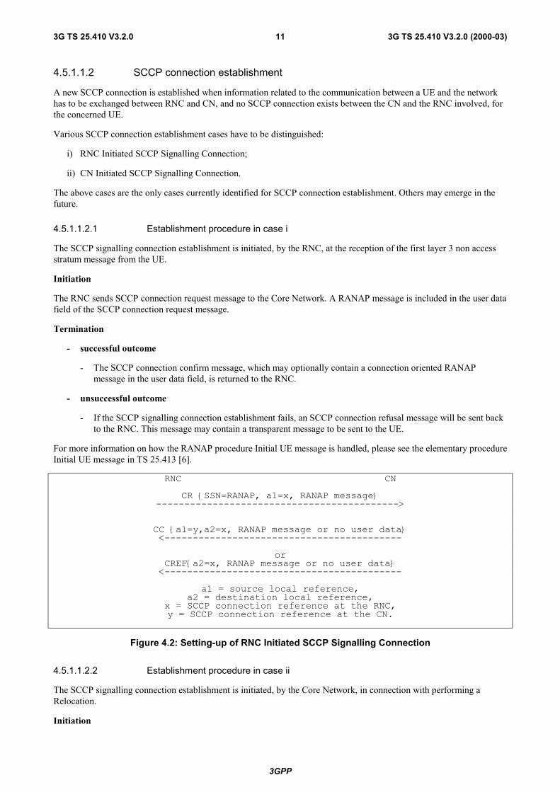
4.5.1.1.2 SCCP connection establishment
A new SCCP connection is established when information related to the communication between a UE and the networkhas to be exchanged between RNC and CN, and no SCCP connection exists between the CN and the RNC involved, forthe concerned UE.
Various SCCP connection establishment cases have to be distinguished:
i) RNC Initiated SCCP Signalling Connection;
ii) CN Initiated SCCP Signalling Connection.
The above cases are the only cases currently identified for SCCP connection establishment. Others may emerge in thefuture.
4.5.1.1.2.1 Establishment procedure in case i
The SCCP signalling connection establishment is initiated, by the RNC, at the reception of the first layer 3 non accessstratum message from the UE.
Initiation
The RNC sends SCCP connection request message to the Core Network. A RANAP message is included in the user datafield of the SCCP connection request message.
Termination
- successful outcome
- The SCCP connection confirm message, which may optionally contain a connection oriented RANAPmessage in the user data field, is returned to the RNC.
- unsuccessful outcome
- If the SCCP signalling connection establishment fails, an SCCP connection refusal message will be sent backto the RNC. This message may contain a transparent message to be sent to the UE.
For more information on how the RANAP procedure Initial UE message is handled, please see the elementary procedureInitial UE message in TS 25.413 [6].
RNC CNCR {SSN=RANAP, a1=x, RANAP message}
------------------------------------------->
CC {a1=y,a2=x, RANAP message or no user data}<------------------------------------------
orCREF{a2=x, RANAP message or no user data}
<------------------------------------------a1 = source local reference,
a2 = destination local reference,x = SCCP connection reference at the RNC,y = SCCP connection reference at the CN.
Figure 4.2: Setting-up of RNC Initiated SCCP Signalling Connection
4.5.1.1.2.2 Establishment procedure in case ii
The SCCP signalling connection establishment is initiated, by the Core Network, in connection with performing aRelocation.
Initiation

3GPP
12 3G TS 25.410 V3.2.0 (2000-03)3G TS 25.410 V3.2.0
The Core Network initiates the connection establishment by sending an SCCP connection request message to the RNC.Optionally, a RANAP message may be included in the user data field of the SCCP connection request message.
Termination
- successful outcome
- The SCCP connection confirm message, which may optionally contain a connection oriented RANAPmessage in the user data field, is returned to the Core Network.
- unsuccessful outcome
- If the SCCP signalling connection establishment fails, an SCCP connection refusal message will be sent backto the Core Network. This message may contain a RANAP message in the user data field.
RNC CNCR {SSN=RANAP, a1=y,RANAP message or no user data}
<-----------------------------------------
CC {a1=x, a2=y, RANAP message or no user data}------------------------------------------>
orCREF{a2=y, RANAP message or no user data}
------------------------------------------>
a1 = source local reference,a2 = destination local reference,
x = SCCP connection reference at the RNC,y = SCCP connection reference at the CN.
Figure 4.3: Setting-up of CN Initiated SCCP Signalling Connection
4.5.1.1.3 SCCP connection release
This procedure is always initiated at the Core Network side.
An SCCP connection is released when the CN realises that a given signalling connection is no longer required.
The CN sends a SCCP Released message.
4.5.1.1.4 General SCCP Abnormal Conditions
If a user-out-of-service information or signalling-point-inaccessible information is received by the RANAP, no newattempt to establish SCCP connections towards the affected point code will be started until the corresponding user-in-service information or signalling-point-accessible information is received.
When a user-out-of-service information or signalling-point-inaccessible is received by the RNC, an optional timer maybe started. When the timer expires, all the SCCP connections towards the affected point code will be released. When theuser-in-service or signalling-point-accessible is received, the timer is stopped.
If for any reason an SCCP connection is released, the optional timer expires or a connection refusal is received whileany of the RANAP procedures are being performed or while a dedicated resource is still allocated, the following actionsare taken:
At RNC:
- Any RNC procedure relating to that connection is abandoned.
- The UTRAN resources allocated to the connection are released.
At Core Network:
- The resources associated with the SCCP connection are cleared as soon as possible.

3GPP
13 3G TS 25.410 V3.2.0 (2000-03)3G TS 25.410 V3.2.0
4.5.2 Use of Transport Network User Plane as User Data Bearer
4.5.2.1 Use of AAL2
AAL2 is used as the user data bearer towards the CS domain.
Q.2630.1 is used as the protocol for dynamically setup AAL-2 connections over Iu towards the CS domain.
4.5.2.2 Use of GTP-U
GTP-U is used as the user data bearer towards the PS domain.
RANAP Signalling is used to establish, modify and release the GTP-U tunnels towards the PS domain.
4.5.3 Use of Transport Network User Plane on Iu-BCTCP/IP is used as the bearer for the radio network layer protocol over Iu-BC.
The TCP connection is normally established by the CN using standard TCP procedures.
A new TCP connection is established by the RNC only when there is information (e.g. failure or restart indications) thatneeds to be sent from RNC to the CN, and there is no existing TCP connection. The RNC shall establish the connectionusing standard TCP procedures.
The node that established the connection shall release the TCP connection.
5 Functions of the Iu Interface Protocols & FunctionalSplit
5.1 GeneralThis subclause defines the functional split between the core network and the UMTS radio access network. In addition,the possible interaction between the functions is defined. The functional split is shown in table 5.1.

3GPP
14 3G TS 25.410 V3.2.0 (2000-03)3G TS 25.410 V3.2.0
Table 5.1: Iu interface functional split
Function UTRAN CNRAB management functions:RAB establishment, modification and release X XRAB characteristics mapping Iu transmission bearers XRAB characteristics mapping Uu bearers XRAB queuing, pre-emption and priority X X
Radio Resource Management functions:Radio Resource admission control XBroadcast Information X X
Iu link Management functions:Iu signalling link management X XATM VC management X XAAL2 establish and release X XAAL5 management X XGTP-U Tunnels management X XTCP Management X XBuffer Management X
Iu U-plane (RNL) Management:Iu U-plane frame protocol management X
Iu U-plane frame protocol initialization X
Mobility management functions:Location information reporting X XHandover and Relocation Inter RNC hard HO, Iur not used or not available X X Serving RNS Relocation (intra/inter MSC) X X Inter system hard HO (UMTS-GSM) X XPaging Triggering X
Security Functions:Data confidentiality Radio interface ciphering X Ciphering key management X User identity confidentiality X XData integrity Integrity checking X Integrity key management X
Service and Network Access functions:CN Signalling data X XData Volume Reporting XUE Tracing X XLocation reporting X X
Iu Co-ordination functions:Paging co-ordination X X
5.2 RAB management Functions
5.2.1 RAB establishment, modification and release functionThe RAB, Radio Access Bearer, is defined to be set-up between UE and CN. Depending on subscription, service,requested QoS etc. different types of RABs will be used. It is the CN that controls towards the UTRAN theestablishment , modification or release of a RAB.
The RAB identity is allocated by CN by mapping the value for the NAS Binding information (from the actual protocolIE for the respective CN domain) to the RAB ID as specified in [15]. The RAB identity is globally significant on boththe radio bearer and on the Iu bearer for a given UE in a particular CN domain.
RAB establishment, modification and release is a CN initiated function.

3GPP
15 3G TS 25.410 V3.2.0 (2000-03)3G TS 25.410 V3.2.0
RAB establishment, modification and release is a UTRAN executed function.
RAB release request is a UTRAN initiated function, triggered when UTRAN fails to keep the RAB established with theUE.
5.2.2 RAB characteristics mapping to Uu bearers functionThe RAB characteristics mapping function is used to map the radio access bearers to the Uu bearers. The mapping isperformed during the establishment of the RAB. UTRAN shall perform the mapping between the bearers.
RAB mapping to Uu transmission bearers is a UTRAN function.
5.2.3 RAB characteristics mapping to Iu transport bearersThe RAB characteristics mapping function is used to map the radio access bearers to the Iu interface transport bearers.The mapping is performed during the establishment of the RAB.
UTRAN shall perform this mapping between the bearers if AAL2 is used, since it is the UTRAN that establish theAAL2 connections.
In case of RAB towards the IP domain, UTRAN shall perform the mapping between the radio access bearers and the IPlayer.
RAB characteristics mapping to Iu transport bearers is a UTRAN function.
5.2.4 RAB queuing, pre-emption and priority functionThe allocation/retention priority level of a RAB is determined by the CN based on e.g. subscription information , QoSinformation etc. Accordingly, the CN shall request RAB establishment or modification with an indication of the prioritylevel and the pre-emption capability of that RAB and the queuing vulnerability. Queuing and resource pre-emption shallbe performed by UTRAN accordingly.
RAB queuing, pre-emption and allocation/retention priority handling is a UTRAN controlled function.
RAB queuing, pre-emption and allocation/retention priority setting is a CN function.
5.3 Radio Resource Management over Iu
5.3.1 Radio resource admission controlThis function is used at radio access bearer establishment and it is divided in two parts:
a) Subscription based admission control
When CN receives a request to establish or modify a radio access bearer, the CN verifies if the subscriber isallowed to use a radio access bearer with the requested parameters. Based on the verification the CN will acceptor reject the request. This part is called "Subscription based admission control" and it is handled by the CN.
b) Radio resource admission control
When UTRAN receives a request to establish or modify a radio access bearer from the CN, the current radioresource situation is analysed and the admission control either accepts or rejects the request. This part is called"Radio resource admission control" and it handled by the UTRAN. If the request is queued, this part is handledby the RAB queuing, pre-emption and priority function.
Part b) is only performed if CN accept the request to establish a radio access bearer.
3GPP
16 3G TS 25.410 V3.2.0 (2000-03)3G TS 25.410 V3.2.0
5.3.2 Broadcast information managementThis function consists in the broadcast from network toward UE of some information in the coverage area of the wholenetwork or different parts of the network.
There are three kinds of Broadcast information management. UTRAN broadcast information, CN broadcast informationand Cell Broadcast information management. All UTRAN broadcast information management shall be handled locallywithin UTRAN. All CN related broadcast information and Cell Broadcast information is controlled by CN. UTRANexecutes the broadcast of CN information and Cell Broadcast information.
5.4 Iu link Management functions
5.4.1 Iu Signalling Link Management functionThe Iu signalling link management function provides a reliable transfer of the radio network signalling between UTRANand CN. Both CN and UTRAN manage the function.
This function is in particular responsible for Iu signalling connection establishment, which can be established either bythe CN or the RNC and for Iu signalling connection release, which is controlled by CN possibly upon UTRAN request.
5.4.2 ATM Virtual Connection Management functionThis function refers to handling of ATM Virtual Connections (VCs) between CN and UTRAN.
This function shall be used to establish, maintain and release the ATM VCs. For permanent VCs, it is regarded to be anO&M function.
This function also includes the selection of a Virtual Circuit to be used for a particular RAB. The selection of ATM VCupon an Iu radio access bearer service request, shall be done by UTRAN. The selected VC shall fulfil the requirementsof the request. The VC may consist of several sublinks: such as SCCP connections, AAL2 connections or IP flows.
5.4.3 AAL2 connection establish and release functionThis function is used to establish and release the AAL type 2 connections between CN and UTRAN upon an Iu radioaccess bearer service request. Both UTRAN and CN are taking part in the establishment of AAL2 connection. UTRANshall initiate both establishment and release of AAL2 connections. The use of AAL2 for Iu transmission bearers dependson type of CN.
5.4.4 AAL5 management functionAAL5 connections between CN and UTRAN shall be pre-configured at system initialisation. Basic configuration isPVCs. For user data, SVC is possible.
The AAL5 management is a function handled by both the CN and the UTRAN.
5.4.5 GTP-U tunnels management functionThis function is used to establish and release GTP-U tunnels between CN and UTRAN upon a radio access bearerservice request. This involves assigning a tunnel identifier for each direction and the creation of a context containing thetunnel information. The tunnel identifier for the downlink is allocated by the UTRAN, and the tunnel identifier for theuplink is allocated by the CN. Both CN and UTRAN should maintain the context. The use of GTP-U for Iu transportbearers depends on type of CN.
5.4.6 TCP Management FunctionThis function is used to establish and release the TCP connections between CN and UTRAN over Iu-BC.
The TCP management function exists in both UTRAN and CN.
3GPP
17 3G TS 25.410 V3.2.0 (2000-03)3G TS 25.410 V3.2.0
5.4.7 Buffer ManagementCongestion control shall be performed over the Iu user plane using buffer management and no flow control.
This function includes buffers to store received packet data units that at reception can not be processed due to e.g.congestion. In UTRAN, there must be a buffer management function handling received packets from the peer CN node.
The used mechanism is not in the scope of this document and not relevant to be standardised.
Buffer management is a UTRAN function.
5.5 Iu U-plane (RNL)Management Functions
5.5.1 Iu U-plane frame protocol mode selection functionThe Iu UP in the Radio Network Layer provides modes of operation that can be activated on RAB basis. For a givenRAB, the Iu UP operates either in a Transparent or in Support mode. Iu U-plane frame protocol mode is selected by theCN.
This function is a CN function.
5.5.2 Iu U-plane frame protocol initialisationIu U-plane frame protocol is initialised by the UTRAN.
5.6 Mobility Management Functions
5.6.1 Location information update functionSome functionality within the CN, needs information about the present location of active UE, i.e. UE with establishedsignalling connection. The Location information update function is used to transfer this information from the UTRAN tothe CN. It is the UTRAN responsibility to send this information initially at the signalling connection establishment foran UE and at any change of the UE location as long as the signalling connection exists. For this function, the locationinformation shall be at Location and Routing Area level.
5.6.2 Handover and Relocation functions
5.6.2.1 Inter RNC hard HO function, Iur not used or not available
This functionality includes procedures for handover from one RNC to other RNC when Iur interface is not used or is notavailable, i.e. soft handover is not possible. The connection is switched in the CN, so both UTRAN and CN areinvolved. Both intra and inter CN entity cases are applicable.
5.6.2.2 Serving RNS Relocation function
This functionality allows moving the Serving RNS functionality from one RNC to an other RNC, e.g. closer to where theUE has moved during the communication. The Serving RNS Relocation procedure may be applied when active cellmanagement functionality has created a suitable situation for it. Both UTRAN and CN are involved.
5.6.2.3 Inter system Handover (e.g. GSM-UMTS) function
Inter system handover is performed when a mobile hands over between cells belonging to different systems such asGSM and UMTS. This may imply also a change of radio access type. For intersystem handover between UMTS andGSM, the GSM procedures are used with the GSM network. Both UTRAN and CN are involved.
NOTE: The GSM BSSMAP procedures are outside the scope of this specification.
3GPP
18 3G TS 25.410 V3.2.0 (2000-03)3G TS 25.410 V3.2.0
5.6.3 Paging TriggeringThe Core Network shall, when considered necessary, trigger the Location/Routing/RNC Area paging in the UTRANsystem.
5.7 Security Functions
5.7.1 Data Confidentiality
5.7.1.1 Radio interface ciphering function
The radio interface shall be ciphered upon request of the Core Network. Both Signalling and user data may be subject tociphering. The ciphering shall be done within UTRAN.
5.7.1.2 Ciphering key management function
The ciphering key and the permitted algorithm shall be supplied by the CN. UTRAN selects the used algorithm.
5.7.2 Data integrity
5.7.2.1 Integrity checking
The purpose of the integrity check is to make sure that the signalling continues between the same elements as byauthentication. The integrity check shall be done within the UTRAN.
5.7.2.2 Integrity key management
The integrity key and the permitted algorithm shall be supplied by the CN. UTRAN selects the used algorithm.
5.8 Service and Network Access Functions
5.8.1 Core Network signalling data transfer functionThe NAS CN signalling data such as Call Control (CC), Session Management (SM), Mobility Management (MM), ShortMessage Services Point to Point and Supplementary Services (SS) shall be transparently conveyed over the Iu interface.The signalling information shall be conveyed transparently over the same Iu interface channel that is used for theUTRAN-CN signalling.
5.8.2 Data Volume ReportingThe data volume reporting function is used to report the volume of unacknowledged data to the CN. The function shallbe in the UTRAN and is triggered from the CN.
5.8.3 UE TracingThis feature allows tracing of various events related to the UE and its activities. This is an O&M functionality.
5.8.4 Location reporting functionThe positioning function performs the determination of the geographical position for an UE. The location reportingfunction transfer the positioning information between the UTRAN and the CN according to CN commands. Thisfunction involves UTRAN and CN.

3GPP
19 3G TS 25.410 V3.2.0 (2000-03)3G TS 25.410 V3.2.0
5.9 Co-ordination Functions
5.9.1 Paging Co-ordination functionThe two CN domain architecture implies need for a page co-ordination, i.e. handling of page triggered by one CN nodewhen UE has a signalling connection to the other CN node. The paging co-ordination is performed by UTRAN and/oroptionally by CN. The Common ID is used for UTRAN paging co-ordination. The CN provides the UTRAN with theCommon ID.
The paging co-ordination is a UTRAN function. Optionally the paging co-ordination may be performed in the CN.
6 Iu Interface Protocol Structure
6.1 GeneralThe Radio Network signalling over Iu consists of the Radio Access Network Application Part (RANAP). The RANAPprotocol consists of mechanisms to handle all procedures between the CN and UTRAN. It is also capable of conveyingmessages transparently between the CN and the UE without interpretation or processing by the UTRAN.
Over the Iu interface the RANAP protocol is, e.g. used for:
- Facilitate a set of general UTRAN procedures from the Core Network such as paging -notification as defined bythe notification SAP in [3].
- Separate each User Equipment (UE) on the protocol level for mobile specific signalling management as definedby the dedicated SAP in [3].
- Transfer of transparent non-access signalling as defined in the dedicated SAP in [3].
- Request of various types of UTRAN Radio Access Bearers through the dedicated SAP in [3].
- Perform the SRNS Relocation function.
The Radio Access Bearers are provided by the Access Stratum.
Over Iu-BC, a datagram mechanism is used, so there is no clear separation of control and user planes, and the SABPprotocol is used for data transfer and signalling.
6.2 Iu-CSFigure 6.1 shows the protocol structure for Iu-CS, following the structure described in [1].

3GPP
20 3G TS 25.410 V3.2.0 (2000-03)3G TS 25.410 V3.2.0
Q.2150.1
Q.2630.1
RANAP Iu UP ProtocolLayer
TransportNetwork
Layer
Physical Layer
TransportUser
NetworkPlane
Control Plane User Plane
TransportUser
NetworkPlane
Transport NetworkControl Plane
RadioNetwork
Layer
ATM
SSCOP
AAL5
SSCOP
SSCF-NNI
AAL2AAL5
MTP3bMTP3b
SCCP
SSCF-NNI
Figure 6.1: Iu �Interface Protocol Structure towards CS Domain
6.3 Iu-BCFigure 6.2 shows the protocol structure for the Iu-BC.

3GPP
21 3G TS 25.410 V3.2.0 (2000-03)3G TS 25.410 V3.2.0
Transport Network
Layer
Radio Network
Layer SABP Protocol Layer
SA Broadcast Plane
Transport User
Network Plane
AAL5
IP
TCP
Physical Layer
ATM
Figure 6.2: Iu Interface Protocol Structure towards Broadcast Domain
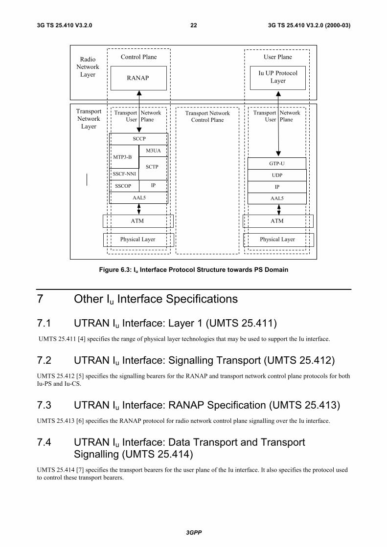
6.4 Iu-PSFigure 6.3 shows the protocol structure for Iu-PS, following the structure described in [1].
3GPP
22 3G TS 25.410 V3.2.0 (2000-03)3G TS 25.410 V3.2.0
SSCF-NNI
SSCOP
AAL5
IP
SCTP
SCCP
SSCF-NNI
MTP3-BM3UA
RANAPIu UP Protocol
Layer
TransportNetwork
Layer
Physical Layer
TransportUser
NetworkPlane
Control Plane User Plane
TransportUser
NetworkPlane
Transport NetworkControl Plane
RadioNetwork
Layer
ATM
AAL5
IP
UDP
GTP-U
Physical Layer
ATM
Figure 6.3: Iu Interface Protocol Structure towards PS Domain
7 Other Iu Interface Specifications
7.1 UTRAN Iu Interface: Layer 1 (UMTS 25.411) UMTS 25.411 [4] specifies the range of physical layer technologies that may be used to support the Iu interface.
7.2 UTRAN Iu Interface: Signalling Transport (UMTS 25.412)UMTS 25.412 [5] specifies the signalling bearers for the RANAP and transport network control plane protocols for bothIu-PS and Iu-CS.
7.3 UTRAN Iu Interface: RANAP Specification (UMTS 25.413)UMTS 25.413 [6] specifies the RANAP protocol for radio network control plane signalling over the Iu interface.
7.4 UTRAN Iu Interface: Data Transport and TransportSignalling (UMTS 25.414)
UMTS 25.414 [7] specifies the transport bearers for the user plane of the Iu interface. It also specifies the protocol usedto control these transport bearers.

3GPP
23 3G TS 25.410 V3.2.0 (2000-03)3G TS 25.410 V3.2.0
7.5 UTRAN Iu Interface: CN-UTRAN User Plane Protocol(UMTS 25.415)
UMTS 25.415 [8] specifies the user plane frame handling protocol for the Iu interface.
7.6 UTRAN Iu Interface: Service Area Broadcast Protocol SABP(UMTS 25.419)
UMTS 25.419 [14] specifies the communication requirements over the Iu interface towards the BC domain.
7.7 SummaryThe present document, UMTS 25.410, specifies the general aspects and principles of the Iu interface as a whole.
The relationship between the other technical specifications that define the UTRAN Iu interface is shown in figure 7.1.
25.413 25.415
TransportNetwork
Layer
25.411
TransportUser
NetworkPlane
Control Plane User Plane
TransportUser
NetworkPlane
Transport NetworkControl Plane
RadioNetwork
Layer
25.412 25.414
25.419
SA Broadcast Plane
TransportUser
NetworkPlane
Figure 7.1: Summary of Iu Interface Specification Structure

3GPP
24 3G TS 25.410 V3.2.0 (2000-03)3G TS 25.410 V3.2.0
Annex A (informative):Change history
Change historyTSG RAN# Version CR Tdoc RAN New Version Subject/CommentRAN_05 - - - 3.0.0 Approved at TSG RAN #5 and placed under Change ControlRAN_06 3.0.0 - - 3.1.0 Approved at TSG RAN #6 and placed under Change ControlRAN_07 3.1.0 - - 3.2.0 Approved at TSG RAN #7
3GPP
25 3G TS 25.410 V3.2.0 (2000-03)3G TS 25.410 V3.2.0
HistoryDocument history