journées micro-drones 2004. presentation high data rate transmission system for micro uavs lep>...
TRANSCRIPT
Journées Micro-Drones 2004. Presentation
High Data Rate Transmission System for Micro UAVs
LEP> SCN
Fabien MULOT: Internship ONERA-SUPAERO
Vincent CALMETTES: Research SUPAERO
Journées Micro-Drones 2004. Presentation
Plan of the presentation
LEP> SCN
Context of the study
Video quality VS data rate trade-off
Characterisation of the micro-UAV transmission channel
Fade mitigation techniques
Future studies and developments
Journées Micro-Drones 2004. Presentation
Context of the study
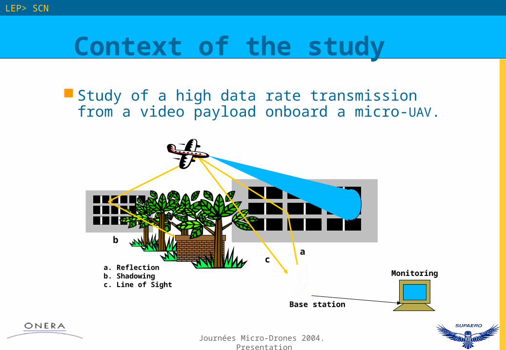
Study of a high data rate transmission from a video payload onboard a micro-UAV.
LEP> SCN
a. Reflectionb. Shadowingc. Line of Sight
ba
c
Monitoring
Base station
Journées Micro-Drones 2004. Presentation
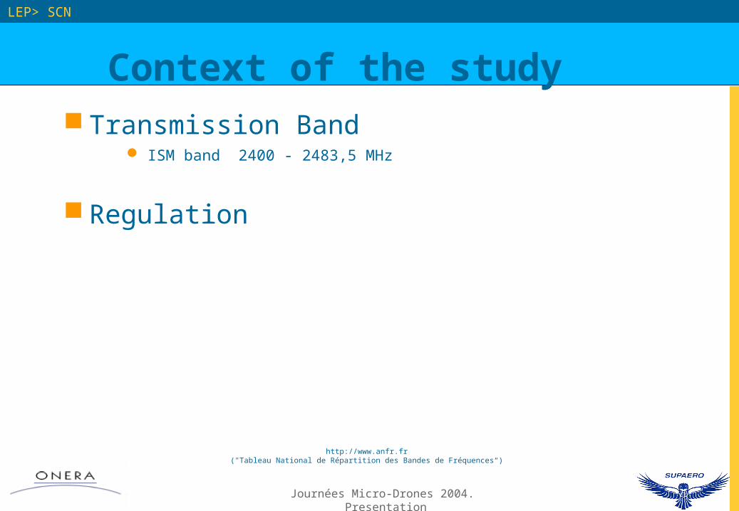
Context of the study Transmission Band
ISM band 2400 - 2483,5 MHz
Regulation
LEP> SCN
http://www.anfr.fr("Tableau National de Répartition des Bandes de Fréquences“)
Journées Micro-Drones 2004. Presentation
LEP> SCN
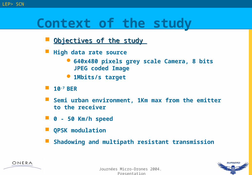
Objectives of the study Objectives of the study
High data rate source 640x480 pixels grey scale Camera, 8 bits JPEG coded
Image 1Mbits/s target
10-7 BER
Semi urban environment, 1Km max from the emitter to the receiver
0 - 50 Km/h speed
QPSK modulation
Shadowing and multipath resistant transmission
Context of the study
Journées Micro-Drones 2004. Presentation
Video quality VS data rate
trade-off
LEP> SCN
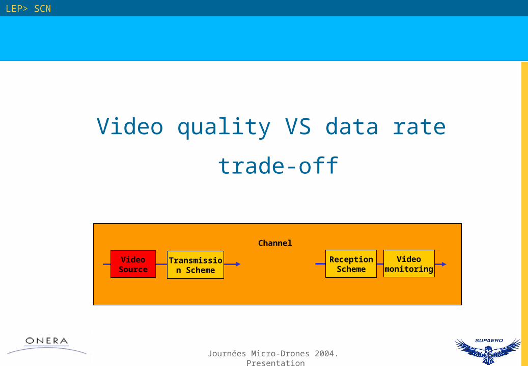
Video Source
Transmission Scheme
Channel
Reception Scheme
Video monitoring
Journées Micro-Drones 2004. Presentation
Video quality VS data rate trade-off
LEP> SCN
A
D
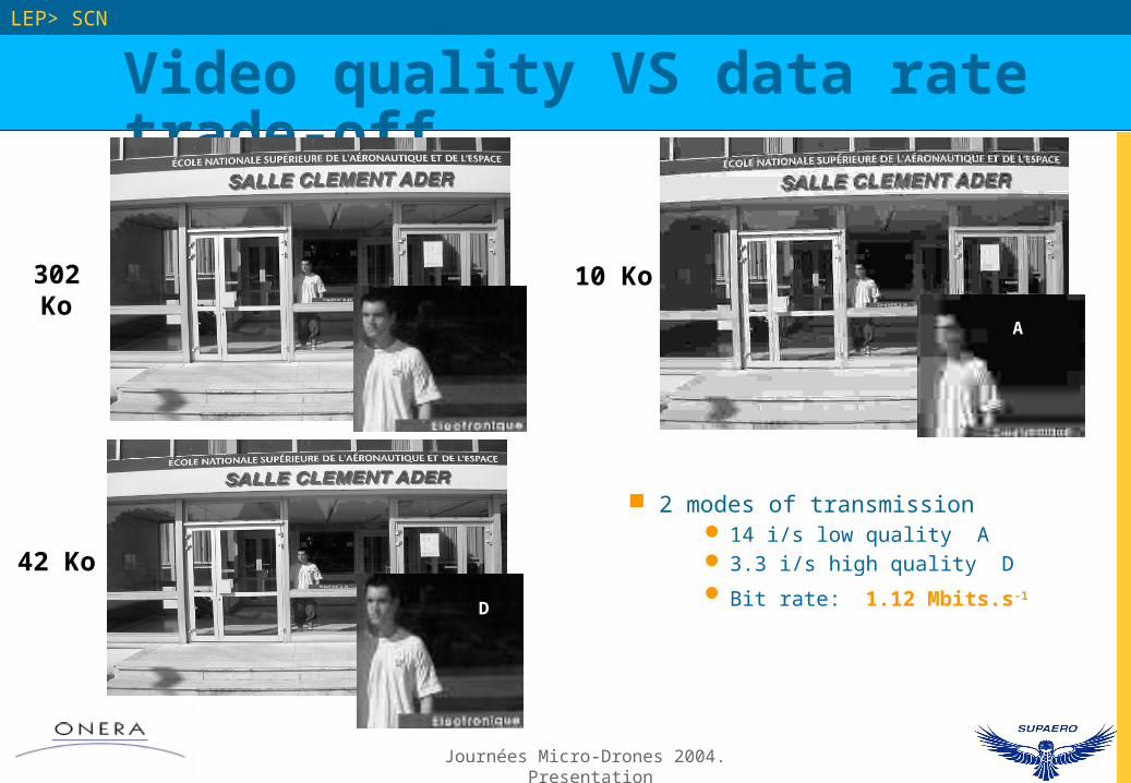
2 modes of transmission 14 i/s low quality A 3.3 i/s high quality D
Bit rate: 1.12 Mbits.s-1
302 Ko
42 Ko
10 Ko
Journées Micro-Drones 2004. Presentation
Characterisation of the
micro-UAV transmission channel
LEP> SCN
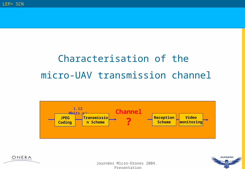
JPEG Coding
Transmission Scheme
Channel
?Reception
SchemeVideo
monitoring
1.12 Mbits.s-1
Journées Micro-Drones 2004. Presentation
Micro-UAV transmission channel
LEP> SCN
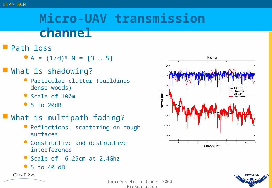
Path lossA = (1/d)N N = [3 ….5]
What is shadowing? Particular clutter (buildings dense woods) Scale of 100m 5 to 20dB
What is multipath fading? Reflections, scattering on rough surfaces Constructive and destructive interference Scale of 6.25cm at 2.4Ghz 5 to 40 dB
Journées Micro-Drones 2004. Presentation
LEP> SCN
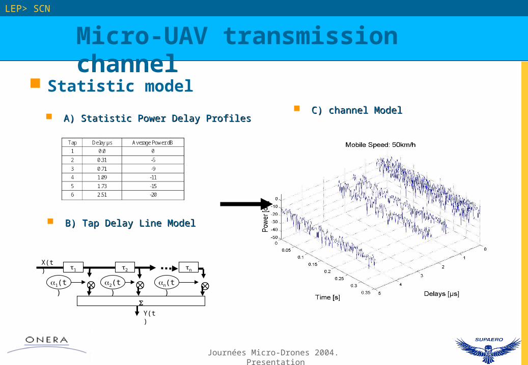
B) Tap Delay Line ModelB) Tap Delay Line Model
Y(t)
1 2 n
1(t) 2(t) n(t)
X(t)
A) Statistic Power Delay ProfilesA) Statistic Power Delay Profiles
Statistic model
Micro-UAV transmission channel
C) channel ModelC) channel Model
Journées Micro-Drones 2004. Presentation
LEP> SCN
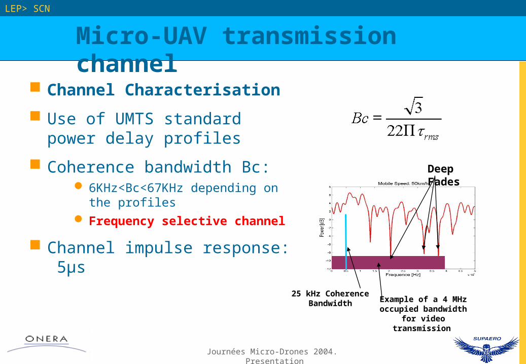
Channel Characterisation
Use of UMTS standard power delay profiles
Coherence bandwidth Bc: 6KHz<Bc<67KHz depending on the
profiles Frequency selective channel
Channel impulse response: 5µs
Micro-UAV transmission channel
25 kHz Coherence Bandwidth Example of a 4 MHz
occupied bandwidth for video transmission
Deep Fades
Journées Micro-Drones 2004. Presentation
LEP> SCN
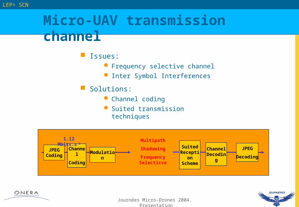
Issues: Frequency selective channel Inter Symbol Interferences
Solutions: Channel coding Suited transmission techniques
Micro-UAV transmission channel
JPEG Coding
Channel
Coding
Multipath
Shadowing
Frequency Selecticve
Suited Reception
Scheme
JPEG
Decoding
1.12 Mbits.s-1
ModulationChannel Decoding
Journées Micro-Drones 2004. Presentation
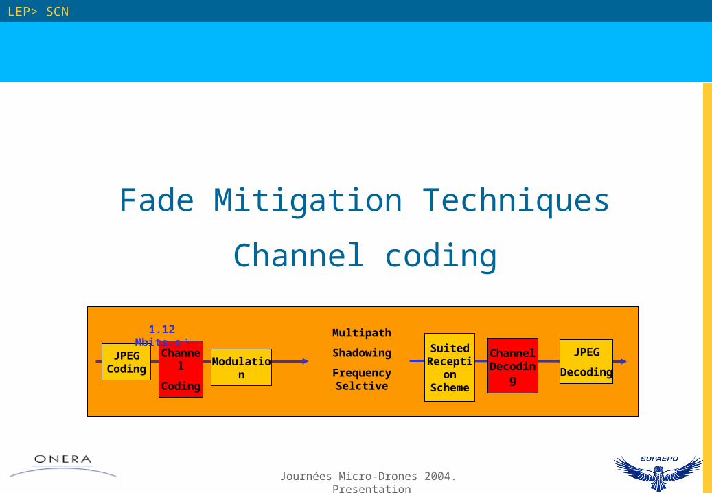
Fade Mitigation Techniques
Channel coding
LEP> SCN
JPEG Coding
Channel
Coding
Multipath
Shadowing
Frequency Selctive
Suited Reception
Scheme
JPEG
Decoding
1.12 Mbits.s-1
ModulationChannel Decoding
Journées Micro-Drones 2004. Presentation
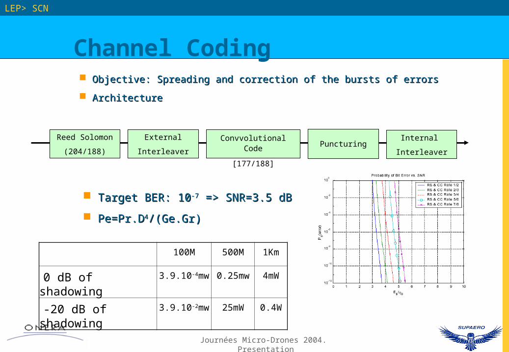
Channel Coding
LEP> SCN
Objective: Spreading and correction of the bursts of errorsObjective: Spreading and correction of the bursts of errors
ArchitectureArchitecture
Reed Solomon
(204/188)
External
Interleaver
Convvolutional Code
[177/188]
Internal
InterleaverPuncturing
Target BER: 10Target BER: 10-7-7 => SNR=3.5 dB => SNR=3.5 dB
Pe=Pr.DPe=Pr.D44/(Ge.Gr)/(Ge.Gr)
100M 500M 1Km
0 dB of shadowing 3.9.10-4mw 0.25mw 4mW
-20 dB of shadowing 3.9.10-2mw 25mW 0.4W
Journées Micro-Drones 2004. Presentation
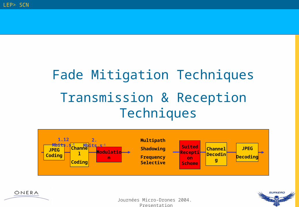
Fade Mitigation Techniques
Transmission & Reception Techniques
LEP> SCN
JPEG Coding
Channel
Coding
Multipath
Shadowing
Frequency Selective
Suited Reception
Scheme
JPEG
Decoding
1.12 Mbits.s-1
ModulationChannel Decoding
2. Mbits.s-1
Journées Micro-Drones 2004. Presentation
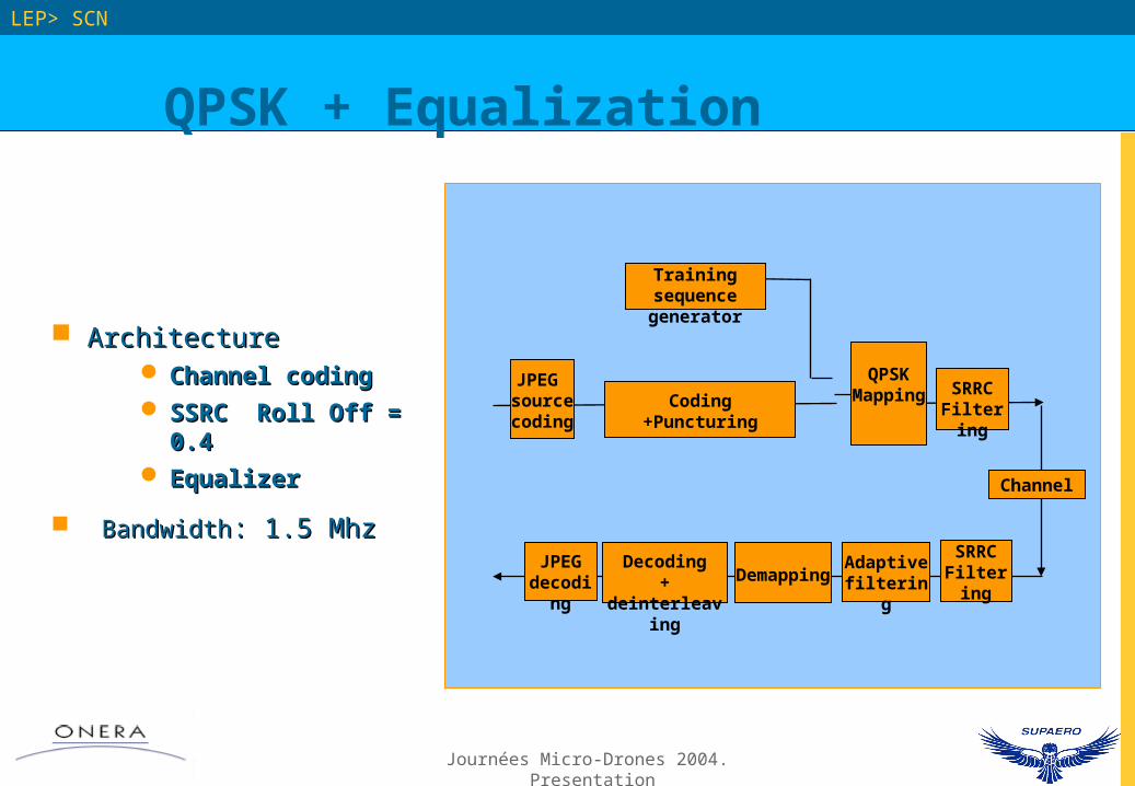
QPSK + Equalization
LEP> SCN
ArchitectureArchitecture Channel codingChannel coding SSRC Roll Off = 0.4SSRC Roll Off = 0.4 EqualizerEqualizer
BandwidthBandwidth: 1.5 Mhz: 1.5 Mhz
JPEG source coding
Coding+Puncturing
SRRCFiltering
QPSK Mapping
SRRCFiltering
Adaptive filteringDemapping
Decoding+ deinterleaving
JPEG decoding
Training sequence generator
Channel
Journées Micro-Drones 2004. Presentation
QPSK + Equalization
LEP> SCN
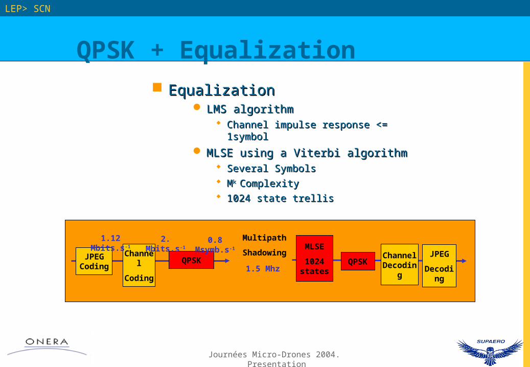
EqualizationEqualization LMS algorithmLMS algorithm
Channel impulse response <= 1symbolChannel impulse response <= 1symbol
MLSE using a Viterbi algorithmMLSE using a Viterbi algorithm Several SymbolsSeveral Symbols MMk k ComplexityComplexity 1024 state trellis1024 state trellis
JPEG Coding
Channel
Coding
Multipath
ShadowingMLSE
1024 states
JPEG
Decoding
1.12 Mbits.s-1
QPSKChannel Decoding
2. Mbits.s-1 0.8 Msymb.s-1
QPSK1.5 Mhz
Journées Micro-Drones 2004. Presentation
OFDM
LEP> SCN
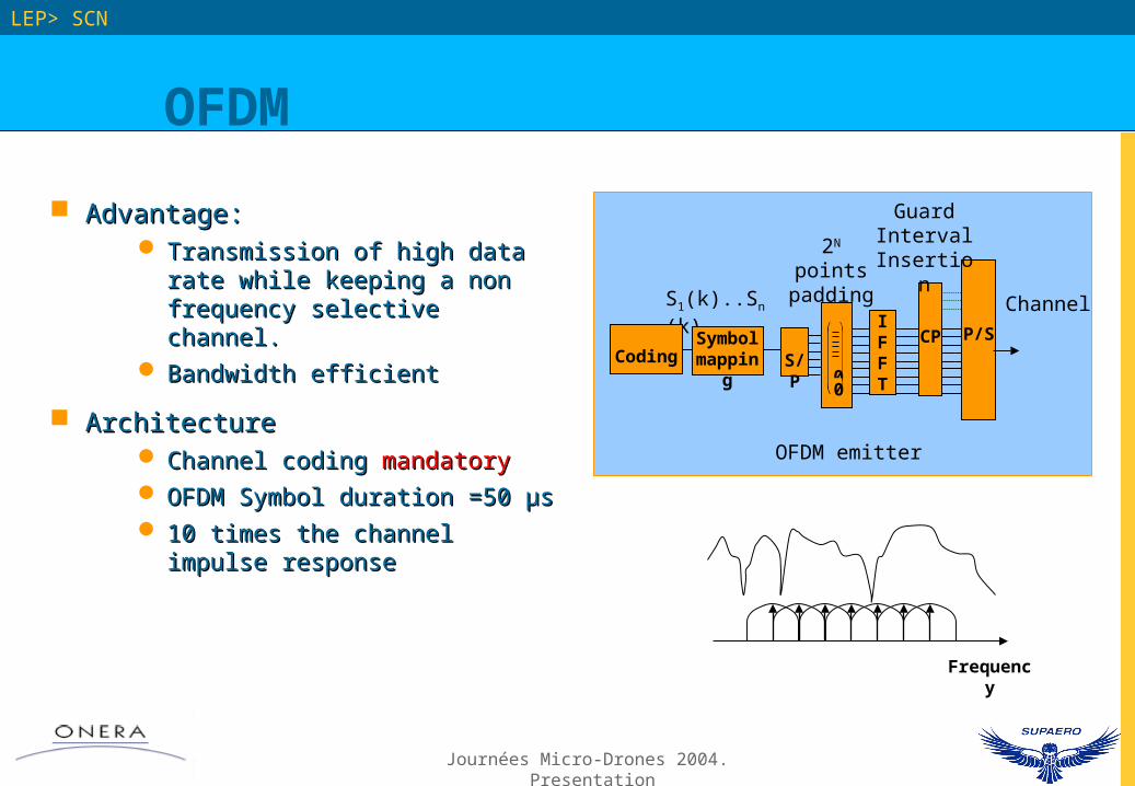
Advantage: Advantage: Transmission of high data rate Transmission of high data rate
while keeping a non frequency while keeping a non frequency selective channel.selective channel.
Bandwidth efficientBandwidth efficient
ArchitectureArchitecture Channel coding Channel coding mandatorymandatory OFDM Symbol duration =50 µs OFDM Symbol duration =50 µs 10 times the channel impulse 10 times the channel impulse
responseresponse
S1(k)..Sn(k)
S/P00
IFFT
CPSymbolmapping
P/S
2N points padding
Channel
Guard Interval Insertion
Coding
OFDM emitter
Frequency

Journées Micro-Drones 2004. Presentation
OFDM
LEP> SCN
Taking into accountTaking into account The symbol duration 50µsThe symbol duration 50µs the length of the cyclic prefixthe length of the cyclic prefix The data rate after codingThe data rate after coding The insertion of training symbols The insertion of training symbols
for equalizationfor equalization 64 points FFT64 points FFT Bandwidth: 1.3MhzBandwidth: 1.3Mhz
JPEG Coding
Channel
Coding
Multipath
Shadowing JPEG
Decoding
1.12 Mbits.s-1
QPSK Channel Decoding
2. Mbits.s-1 0.8 Msymb.s-1
QPSK1.3 Mhz
OFDM 64pts IFFT
20 Ksymb
OFDM 64 pts FFT
Journées Micro-Drones 2004. Presentation
DSSS + Rake
LEP> SCN
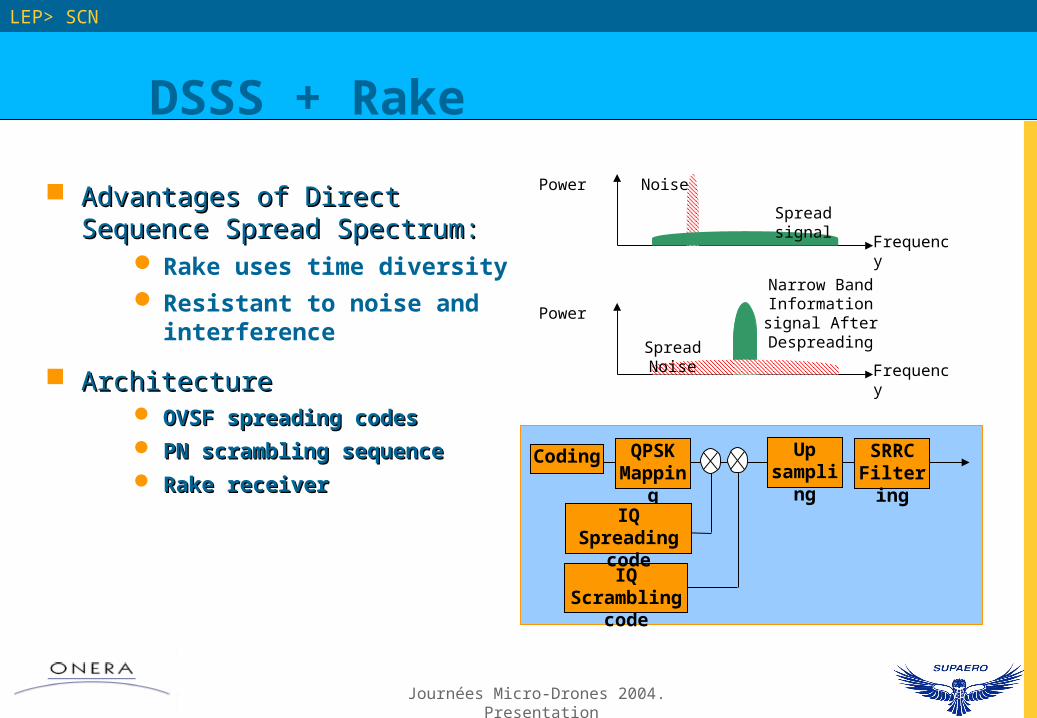
Advantages of Direct Sequence Advantages of Direct Sequence Spread Spectrum: Spread Spectrum:
Rake uses time diversity Resistant to noise and
interference
ArchitectureArchitecture OVSF spreading codesOVSF spreading codes
PN scrambling sequencePN scrambling sequence
Rake receiverRake receiver
Power
Frequency
Noise
Spread signal
Power
Frequency
Narrow Band Information signal After Despreading
Spread Noise
IQ Scrambling code
Up sampling
SRRCFiltering
QPSKMapping
IQ Spreading code
Coding

Journées Micro-Drones 2004. Presentation
∫dt
∫dt 2
1
∫dt
∫dt
IQ demapper
3
4
Path Search
Descramble Despread
Integrate and Dump
Channel estimation
y(t-1)
y(t-2)
y(t-3)
y(t-4)
y(t)
g*(t-1)
g*(t-2)
g*(t-3)
g*(t-4)
MRC
DSSS + Rake
LEP> SCN
Rake Receiver ArchitectureRake Receiver Architecture
Journées Micro-Drones 2004. Presentation
DSSS + Rake
LEP> SCN
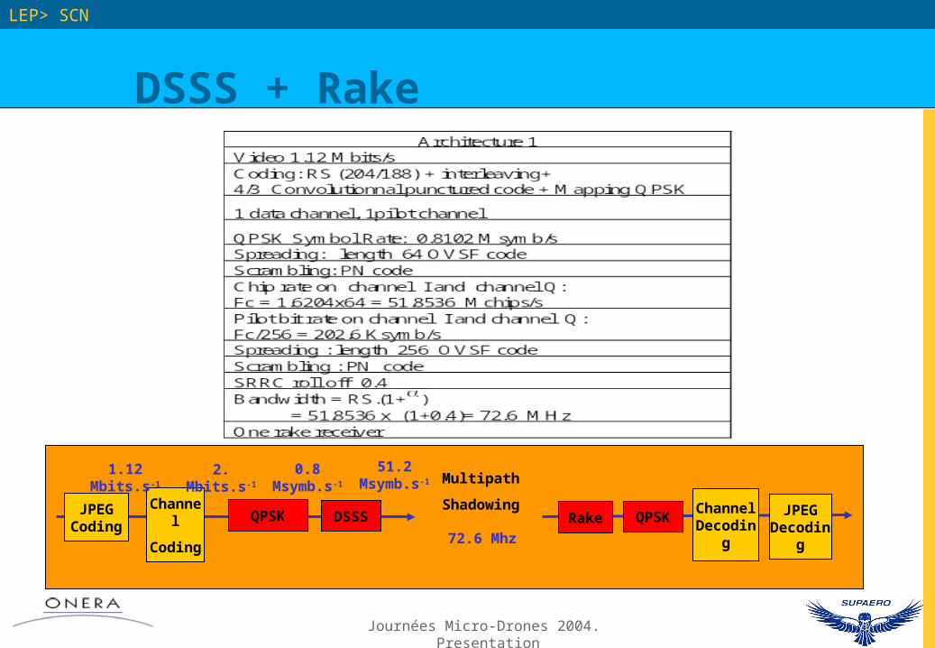
JPEG Coding
Channel
Coding
Multipath
Shadowing JPEG Decoding
1.12 Mbits.s-1
QPSK Channel Decoding
2. Mbits.s-1 0.8 Msymb.s-1
QPSK
72.6 Mhz
DSSS
51.2 Msymb.s-1
Rake

Journées Micro-Drones 2004. Presentation
Future studies and developments
LEP> SCN

Journées Micro-Drones 2004. Presentation
Future studies and developments
LEP> SCNLEP> SCN
Evaluation of a system Evaluation of a system based on existing based on existing commercial technologies:commercial technologies:
WI-FI [802.11b] WI-FI [802.11b] DSSSDSSS 1 to 11 Mbps1 to 11 Mbps
WI-FI [802.11g] WI-FI [802.11g] OFDMOFDM 1 to 54 Mbps1 to 54 Mbps
Baseband Processor
Transceiver External PA
ATHEROS
5523
ATHEROS
5112
FPGA
Baseband Processor
Transceiver
ATHEROS
5523
ATHEROS
5112
USB 2.0Interface
ATHEROS AR5005uX
? FEC ?

Journées Micro-Drones 2004. Presentation
LEP> SCNLEP> SCN
Thank you
Questions ?
Journées Micro-Drones 2004. Presentation
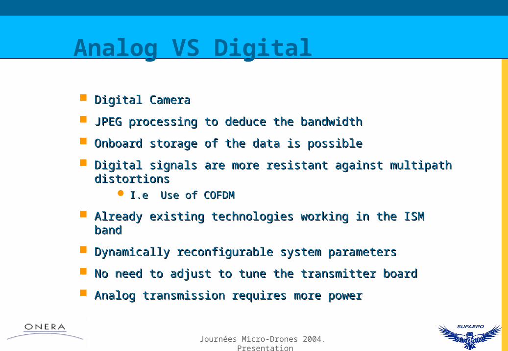
Analog VS Digital
Digital CameraDigital Camera
JPEG processing to deduce the bandwidthJPEG processing to deduce the bandwidth
Onboard storage of the data is possibleOnboard storage of the data is possible
Digital signals are more resistant against multipath distortionsDigital signals are more resistant against multipath distortions I.e Use of COFDMI.e Use of COFDM
Already existing technologies working in the ISM bandAlready existing technologies working in the ISM band
Dynamically reconfigurable system parametersDynamically reconfigurable system parameters
No need to adjust to tune the transmitter boardNo need to adjust to tune the transmitter board
Analog transmission requires more powerAnalog transmission requires more power