journal welding safety 3
TRANSCRIPT

Cop
yrig
ht ©
2011
WTI
ASlide 1
Welding Electrical Safety
Glen AllanEducation & Training Manager

Cop
yrig
ht ©
2011
WTI
ASlide 2
Myth Busting – True or False
• Electric shock is something welders should expect in a days work
• Welders have to learn to get used to electric shock• Welders are capable of sustaining higher levels of
electric shock than other people• The electric shocks that welders get from welding
power sources are from a low voltage source & are harmless
• All welding power sources have the same electrical hazard
• A current of 1/10th of one amp (100 mA) for 1 second can (& likely will) kill you (even if you are a welder)

Cop
yrig
ht ©
2011
WTI
ASlide 3
Hazard Identification & Control
• Elimination• Can the cause of the hazard be eliminated?
• Substitution• Can the cause of the hazard be substituted by something less risky?
• Isolation• Can the hazard be isolated from people?
• Engineering Control• Can the design be changed or safety barriers introduced?
• Administrative Control• Includes training, procedures, permits, & safety signs.
• Personal Protective Equipment (& Clothing)• Should be used if the first four measures are not sufficient – However
PPE may be the only barrier to many hazards encountered in cutting and welding.
Cop
yrig
ht ©
2011
WTI
ASlide 4
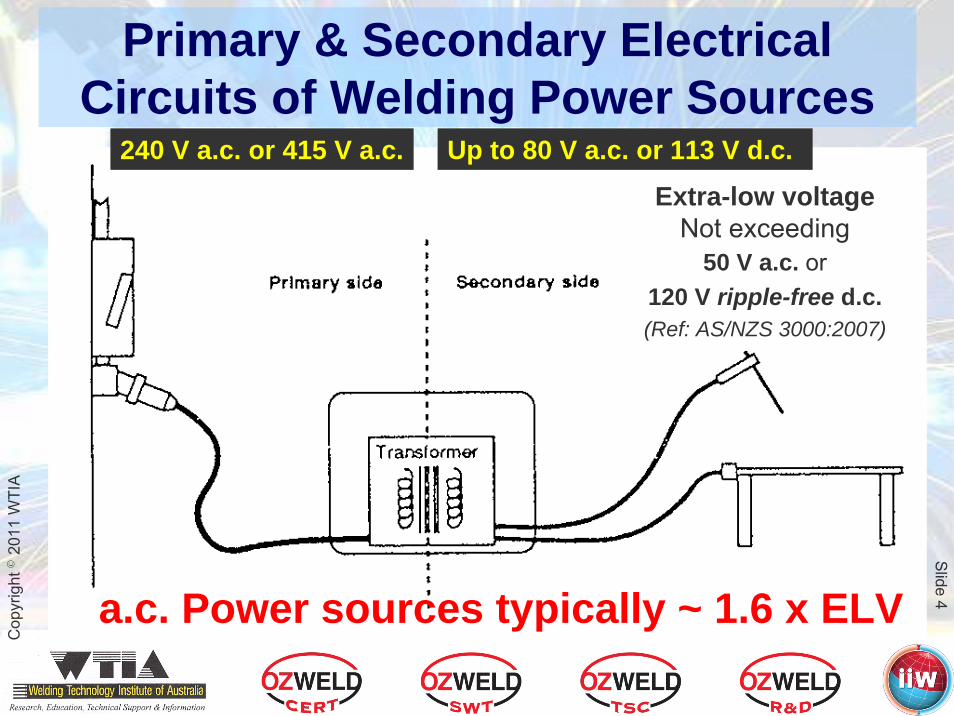
Primary & Secondary ElectricalCircuits of Welding Power Sources
Up to 80 V a.c. or 113 V d.c.240 V a.c. or 415 V a.c.
Extra-low voltageNot exceeding
50 V a.c. or 120 V ripple-free d.c.(Ref: AS/NZS 3000:2007)
a.c. Power sources typically ~ 1.6 x ELV

Cop
yrig
ht ©
2011
WTI
ASlide 5
The Unpublicised Hazard of a.c.
• Extra-low voltage (ELV) – Not exceeding 50 V rms a.c. or 120 V ripple-free d.c.
• (Ref: AS/NZS 3000:2007 Cl.1.4.98 (a))
• Extra-low voltage – can be worked on without isolation – with suitable precautions – (Refer WorkCover NSW Code of Practice – “Low Voltage Electrical Work”)
• a.c. welding power sources are typically ~ 1.6 x ELV!• Who would touch a welding circuit?• Particularly an a.c. type!
The differences in physiological effects of a.c. & d.c. are explained in AS 60479 – “Effects of current on human beings and livestock Part 1: General aspects”

Cop
yrig
ht ©
2011
WTI
ASlide 6
Constant Current (CC) Power Sources
• Drooping volt-amp curve • “Constant” current in the operating
range• Voltage changes with arc length –
only a minor change to amperage• Limited short-circuit current for
reduced stubbing & low spatter• Used for MMAW (stick), some wire
feeders (variable speed), air carbon-arc gouging
• May be d.c.+ve, d.c.-ve or a.c.• High no-load voltage necessary for
arc starting & re-ignition especially for a.c. and “low hydrogen” rods
• High no-load voltages on these power sources exceed ELV for a.c. and d.c with ripple
0102030405060708090
100
100
110
120
130
140
Current AmpsV
olta
ge Striking Voltage for GP electrodes
Striking Voltage for LH electrodes

Cop
yrig
ht ©
2011
WTI
ASlide 7
0102030405060708090
100
100
110
120
130
140
Current Amps
Vol
tage
Constant Voltage (CV) Power Sources
• Relatively flat volt-amp curve• Maintains a relatively stable,
consistent voltage regardless of the amperage output
• Current increases rapidly with decreased voltage
• High short-circuit current helps to maintain a consistent arc length
• Used for wire feeder processes with constant wire feed
• Usually d.c. electrode +ve output (–ve for some applications)
• Much lower no-load voltage with d.c. output makes these power sources inherently safer

Cop
yrig
ht ©
2011
WTI
ASlide 8
Are Electric ArcWelding Circuits Hazardous?
Applied VoltageApplied VoltagePower Power SourceSource
WorkWork
ElectrodeElectrode
22 fatalities in Australia 22 fatalities in Australia 1958 to 19961958 to 1996
Cannington Mine 1997Cannington Mine 1997
Five fatalities in Australia Five fatalities in Australia in the past 10 yearsin the past 10 years
ACMEWelding
Inc.

Cop
yrig
ht ©
2011
WTI
ASlide 9
Amperage effects – a.c.Short exposure – @ 50 Hz
Threshold of reaction – 0.5 mA
Threshold of “let-go” – 10 mAPain, cramps, muscle control increasingly difficult – tending towards immobilisation – 0.5-10 mA
Intense pain, severe cramps, loss of voluntary muscle control, involuntary movements – 10-30 mA
Loss of consciousness – 60 mA
Heart cramps increasing risk of ventricular fibrillation – 50 mA
Ventricular fibrillation – 70 mA
Probability of death very high > 70 mA
Threshold of ventricular fibrillation – 30 mA
10050
0
Body Current
mA
Refer AS/NZS 60479.1 2010 Effects of current on human beings and livestock Part 1: General Aspects – Section 5

Cop
yrig
ht ©
2011
WTI
ASlide 10
Amperage effects – d.c.Short exposure – ripple free
Threshold of reaction – 2 mA
Sensation only at making & breaking of the current with the possibility of involuntary movements and cramp like sensation, no loss of voluntary muscle control –10-30 mA
Loss of consciousness > 300 mA
For longitudinal rising current(feet positive), duration shorter than 0.2 sec – threshold of ventricular fibrillation– 30 mA – (as for a.c.)
10050
0
For longitudinal downward current (feet negative),
duration shorter than 0.2 sec – threshold of ventricular fibrillation
– 60 mA – (2 x a.c.)
Sensation of warmthin the extremities & painful
sensations on the skin – 100 mA
Transverse currents cause reversible cardiac dysrhythmias, current marks, burns, dizziness & sometimes unconsciousness – up to 300 mA
Body Current
mA
Cop
yrig
ht ©
2011
WTI
ASlide 11
Welding Environments
• Australian Standard 1674.2 classifies welding environments into three categories
Category “A”
Category “B”
Category “C”

Cop
yrig
ht ©
2011
WTI
ASlide 12
Allowable Voltages – WeldingAS 1674.2 – 2007, WTIA TN 7 – 2004, WTIA TN 22 - 2003
Not Permitted35 volts peak
or25 volts r.m.s.
Not Permitted35 voltsAS 1674.2
Category CElectrically
Hazardous (wet)
35 volts peak or
25 volts r.m.s.
68 volts peak or
48 volts r.m.s.35 volts113 volts
AS 1674.2 Category BElectrically
Hazardous (dry)
113 volts peak or 80 volts r.m.s.113 voltsAS 1674.2
Category ANon electrically
Hazardous
Working Without an Observer
Working With an Observer
Working Without an Observer
Working With an Observer
Maximum OCV – a.c.Maximum OCV –d.c.(ripple free)
Environment

Cop
yrig
ht ©
2011
WTI
ASlide 13
AS 1674.2 – Welding Environments
• Definition• 1.3.6.1 Category A environment• 1.3.6.2 Category B environment • 1.3.6.3 Category C environment
• Classification• 2.2 (a) Category A environment• 2.2 (b) Category B environment• 2.2 (c) Category C environment
• Control measures• 2.3.1 Category A environment• 2.3.2 Category B environment• 2.3.3 Category C environment
Cop
yrig
ht ©
2011
WTI
ASlide 14
Welding EnvironmentsCategory A
• Category A environment (AS 1674.2 Clauses 1.3.6.1, 2.2 (a) & 2.3.1) is where the risk of electric shock or electrocution is low due to robust controls to prevent the possibility of the welder or other personnel being in contact with the work piece in the event of being in contact with a live part of the welding circuit
• Great care is required to maintain a (fully insulated) Category A environment
• Category A rarely exists in general fabrication but may be achieved in closely controlled manufacturing or training environments
Cop
yrig
ht ©
2011
WTI
ASlide 15
Welding Environments With Increased Hazard – Category B
• Category B environment (AS 1674.2 Clauses 1.3.6.2, 2.2 (b) & 2.3.2) applies whenever the welder has to work in a situation where body parts could come in contact with conductive materials
• This could be due to• The size and form of the work piece• The welders freedom of movement is restricted so the
welder has to perform welding in a position requiring body support, such cramped conditions or where the welder is braced against or kneeling, sitting or lying on metal parts

Cop
yrig
ht ©
2011
WTI
ASlide 16
Welding Environments Category B or Category C?
The situation is far worsewhen moisture is present
• With only moderate levels of moisture added there is no secondary insulation from clothing or PPE
• Recent studies have shown just how little moisture is required (around 5%) to render clothing and other PPE ineffective – this is a long way short of wringing wet!
• We now have a Category C environment

Cop
yrig
ht ©
2011
WTI
ASlide 17
Welding Environments With Increased Hazard – Category C
• Category C environment (AS 1674.2 Clauses 1.3.6.3, 2.2 (c) & 2.3.3) is where the risk of an electric shock or electrocution by the welding circuit is greatly increased due to low body impedance of the welder combined with a significant risk of the welder contacting the workpiece or other parts of the welding circuit
• Low body impedance is likely in the presence of water, moisture or heat, particularly where the ambient temperature is above 32 °C.

Cop
yrig
ht ©
2011
WTI
ASlide 18
Welding Environments With Increased Hazard – Category C
• In wet, moist or hot locations, humidity or perspiration considerably reduces the skin resistance of human bodies and the insulating properties of personal protective equipment accessories and clothing
• It may be possible to derate Category B and Category C environments, where effective control measures are taken to eliminate or reduce the risk (e.g., air conditioning, special insulating clothing).

Cop
yrig
ht ©
2011
WTI
ASlide 19
Consider a typical Category B situation
• The welding power source OCV (no-load voltage) is under 30 V• We will consider possible outcomes for both a.c. and d.c.
power sources
• The welder’s total body resistance is initially at 50,000 Ω or more
• The resulting maximum body current passing through the welder is 0.6 mA
This is just perceptible for a.c and well below threshold of perception
for d.c.
Cop
yrig
ht ©
2011
WTI
ASlide 20
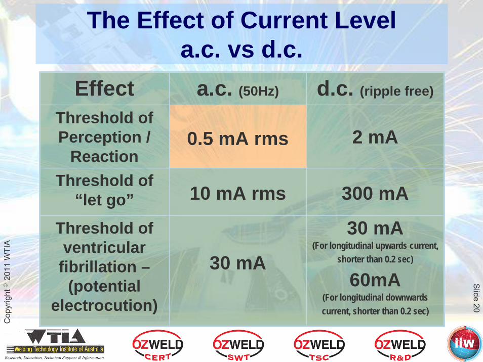
The Effect of Current Levela.c. vs d.c.
30 mA(For longitudinal upwards current,
shorter than 0.2 sec)
60mA(For longitudinal downwardscurrent, shorter than 0.2 sec)
300 mA
2 mA
d.c. (ripple free)
30 mA
10 mA rms
0.5 mA rms
a.c. (50Hz)
Threshold of ventricular fibrillation –
(potential electrocution)
Threshold of “let go”
Threshold of Perception /
Reaction
Effect

Cop
yrig
ht ©
2011
WTI
ASlide 21
A Typical Category B Situation
• Due to mild exertion and slight perspiration the welders total body resistance drops to 5,000 Ω
• A current of 6 mA now flows in the welders body• The current is perceptible for both a.c. & d.c. modes &
feels quite unpleasant• For a.c. this current could result in partial immobilisation
and is rapidly approaching the level where “let-go” is not possible
For a.c. a minor increase in current level increases the risk of involuntary movement followed by contact with
more vulnerable body parts

Cop
yrig
ht ©
2011
WTI
ASlide 22
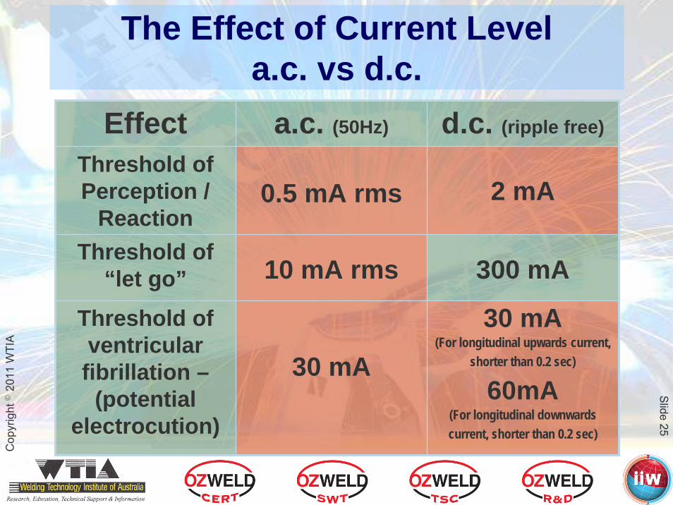
The Effect of Current Levela.c. vs d.c.
30 mA(For longitudinal upwards current,
shorter than 0.2 sec)
60mA(For longitudinal downwardscurrent, shorter than 0.2 sec)
300 mA
2 mA
d.c. (ripple free)
30 mA
10 mA rms
0.5 mA rms
a.c. (50Hz)
Threshold of ventricular fibrillation –
(potential electrocution)
Threshold of “let go”
Threshold of Perception /
Reaction
Effect

Cop
yrig
ht ©
2011
WTI
ASlide 23
Maintain Category B or drift towards a Category C Situation?
• The situation has deteriorated further due to a combination of temperature, exertion, & a moist environment
• The welder gets an electric shock that is a little more serious than a “tingle” – and gets a surge of adrenalin
• Total body resistance has dropped to 2,500 Ω• A current of 12 mA is now flowing!• This current is now potentially life threatening for
a.c. due to the welder being unable to “let-go”
Current mode is critical

Cop
yrig
ht ©
2011
WTI
ASlide 24
Maintain Category B or drift towards a Category C Situation?
• The situation has deteriorated even further due to a combination of temperature, exertion, a moist environment, the adrenalin and a hole in the clothing
• Total body resistance has dropped to 1,000 Ω• A current of 30 mA is now flowing!• This current is now at the threshold of potentially life
threatening for both a.c. & d.c. modes, particularly a.c.
Current mode, exposure time & current path are now critical
Cop
yrig
ht ©
2011
WTI
ASlide 25
The Effect of Current Levela.c. vs d.c.
30 mA(For longitudinal upwards current,
shorter than 0.2 sec)
60mA(For longitudinal downwardscurrent, shorter than 0.2 sec)
300 mA
2 mA
d.c. (ripple free)
30 mA
10 mA rms
0.5 mA rms
a.c. (50Hz)
Threshold of ventricular fibrillation –
(potential electrocution)
Threshold of “let go”
Threshold of Perception /
Reaction
Effect

Cop
yrig
ht ©
2011
WTI
ASlide 26

Cop
yrig
ht ©
2011
WTI
ASlide 27

Cop
yrig
ht ©
2011
WTI
ASlide 28
Electrically Hazardous Situations for Welders
• Whenever body movement is restricted• Whenever in contact with live parts of the work• Whenever there is increased moisture/humidity
(perspiration affecting clothing and PPE must be considered)

Cop
yrig
ht ©
2011
WTI
ASlide 29
Effectiveness of Insulation
• Integrity of insulating material is critical• The smallest perforations expose the welder to an
electrocution – this applies equally to the welding circuit• Fatal shocks can occur at < 1/1000 of welding
currents• A single strand of a frayed cable can deliver enough current
for a fatal shock to a welder• Dry secondary insulation materials adequately
prevent electric shocks – gloves, boots clothing• As moisture levels rise the resistance of all porous materials
drops dramatically
As little as 5% moisture negatesany secondary insulation effect

Cop
yrig
ht ©
2011
WTI
ASlide 30
Work Return Circuit
• Commonly incorrectly referred to as the “Earth”• Calling the return path “earth” encourages
muddled thinking, reaffirms a poor understanding of welding circuits and often results in unintentionally dangerous situations
• In most circumstances all efforts should be made to insulate the welding circuit from earth
Refer article “Returning to Earth”Australasian Welding Journal –
1st Quarter 2008
Cop
yrig
ht ©
2011
WTI
ASlide 31
Hazard Reducing Devices
Power Switching Devices& Voltage Reduction Devices

Cop
yrig
ht ©
2011
WTI
ASlide 32
Effect of Power Switching & VRDs
• A power switch or a VRD significantly reduces the window of opportunity or risk of welders being exposed to a lethal no-load voltage
• No current flows if the power is switched off, or• Currents that may flow through a welders body are
significantly reduced at lower voltages controlled by a VRD
• Response time for a VRD to reduce the voltage after the welding arc is broken is a critical factor
VRDs do not provide protection in all situations!

Cop
yrig
ht ©
2011
WTI
ASlide 33
Integrated VRDWelding Power Supplies
• Welding power supplies with a VRD fitted internally either to the primary circuit or the secondary circuit
• This is an additional safety feature because it prevents accidental or deliberate bypassing of the VRD function
• VRDs in whichever form are electronic or electromechanical devices
Most VRDs ARE NOT “Fail to safe”• If a VRD is offered as “fail to safe”
“Please show me the FMECA to validate your claim”

Cop
yrig
ht ©
2011
WTI
ASlide 34

Cop
yrig
ht ©
2011
WTI
ASlide 35
– Summary –Electric Arc Welding
• This presentation aimed to raise awareness that:• There is an inherent electrical hazard in electric arc welding• The risk is dependent on the welding environment• Welding environments are categorized as Cat. A, Cat. B or
Cat. C in accordance with AS 1674.2 – 2007 “Health and safety in welding – Part 2 – Electrical”
• There are differences in physiological effects of d.c. current & a.c. current on the human body, hence there are different levels of electrical hazard with different types of welding power sources:
d.c output in preference to a.c. output
MIG/MAG/Flux-cored in preference to Stick• The electrical hazard can be managed by education,
implementation of better work practices, substituting safer processes and better informed choices of equipment
