journal of the brazilian society of mechanical sciences and engineering - carbon dioxide evaporation...
TRANSCRIPT

25/11/13 Journal of the Brazilian Society of Mechanical Sciences and Engineering - Carbon dioxide evaporation in a single microchannel
www.scielo.br/scielo.php?pid=S1678-58782006000100008&script=sci_arttext 1/19
Services on Demand
Article
pdf in English
Article in xml format
Article references
How to cite this article
Automatic translation
Send this article by e-mail
Indicators
Cited by SciELO
Access statistics
ReadCube
Related links
Bookmark
|More
Permalink
Journal of the Brazilian Society of MechanicalSciences and EngineeringPrint version ISSN 1678-5878
J. Braz. Soc. Mech. Sci. & Eng. vol.28 no.1 Rio de Janeiro Jan./Mar. 2006
http://dx.doi.org/10.1590/S1678-58782006000100008
TECHNICAL PAPERS
Carbon dioxide evaporation in a singlemicrochannel
José L. Gasche
Emeritus Member, ABCM; Department of Mechanical Engineering;Universidade Estadual Paulista – UNESP; Av. Brasil Centro 56; 15385-000Ilha Solteira, SP, Brazil; [email protected]
ABSTRACT
Despite its importance for designing evaporators and condensers, a review of the literature shows that heattransfer data during phase change of carbon dioxide is very limited, mainly for microchannel flows. In order to givea contribution on this subject, an experimental study of CO2 evaporation inside a 0.8 mm-hydraulic diametermicrochannel was performed in this work. The average heat transfer coefficient along the microchannel wasmeasured and visualization of the flow patterns was conducted. A total of 67 tests were performed at saturationtemperature of 23.3°C for a heat flux of 1800 W/(m2°C). Vapor qualities ranged from 0.005 to 0.88 and mass fluxranged from 58 to 235 kg/(m2s). An average heat transfer coefficient of 9700 W/(m2°C) with a standarddeviation of 35% was obtained. Nucleate boiling was found to characterize the flow regime for the testconditions. The dryout of the flow, characterized by the sudden reduction in the heat transfer coefficient, wasidentified at vapor qualities around 0.85. Flow visualization results showed three flow patterns. For low vaporqualities (up to about 0.25), plug flow was predominant, while slug flow occurred at moderated vapor qualities(from about 0.25 to 0.50). Annular flow was the flow pattern for higher vapor qualities.
Keywords: Carbon dioxide, microchannel, evaporation, flow pattern, heat transfer coefficient
Introduction
It is widely known that the synthetic halocarbons used in refrigerating and air-conditioning systems are nowphased out owing to their negative impact on the global environment. Promising alternatives for refrigerationtechnology are substances called by natural fluids, because of their negligible global warming potential (GWP).Among these fluids one can mention refrigerants like the hydrocarbons, ammonia, and carbon dioxide. If non-toxicand non-flammable fluid is required, carbon dioxide (CO2) is a competitive refrigerant and has gained much
attention recently.1

25/11/13 Journal of the Brazilian Society of Mechanical Sciences and Engineering - Carbon dioxide evaporation in a single microchannel
www.scielo.br/scielo.php?pid=S1678-58782006000100008&script=sci_arttext 2/19
In addition to this environmental benefit, CO2 has excellent thermo physical properties. It has a much smaller
surface tension and liquid viscosity. In consequence, bubble formation is facilitated due to the decreased surfacetension, resulting in higher boiling heat transfer coefficient, while smaller pressure drop can be found due to thedecreased liquid viscosity. The properties of the critical point (31°C and 74 bar) indicate that the pressure level isfar higher in CO2 systems than in conventional systems, which has the disadvantage of requiring the development
of suitable components. On the other hand, the high-pressure level permits the design of systems with smallcomponent dimensions and low compression ratios, which improve compressor efficiency.
As examples mentioned by Cavallini (1996), carbon dioxide has been successfully used in a prototype automotiveair conditioner (an application with high direct global warming impact when using HFC134a), and excellentprospects are also predicted in commercial refrigerating units with associated tap-water heating, and in high-temperature-range heat pumps.
Associated with the compactness resulted from the use of CO2 as working fluid, the use of the microchannel
technology (channel having hydraulic diameter of less than 2 mm) in the heat exchangers design yields to verycompact and lightweight equipments. The high heat transfer coefficients and significant potential in decreasingthe heat exchanger surface area are the major advantages of using this kind of geometry. For these reasonsmicrochannel heat exchangers have been used in bioengineering and microeletronics as well as in evaporators andcondensers of refrigeration systems.
Regarding to the refrigeration systems application, the heat transfer performance of the evaporator is one of theimportant features of the successful operation of the refrigeration unit. Since the optimum design of theevaporator depends on the correct evaluation of the heat transfer characteristics of the flow during the phasechange of the refrigerant, the knowledge of data on two-phase flow and heat transfer is essential.
Studies on two-phase flow and heat transfer in microchannel geometries have mostly been focused on low-pressure refrigerants, and air/water systems at atmospheric pressure. Even for conventional fluids, the knowledgeon microchannel flow and heat transfer is limited, Pettersen (2001). There are few previous works on systematicexperimental investigation of carbon dioxide heat transfer and its modeling.
Good reviews of microchannel heat transfer can be found in Zhao et al. (2000), Pettersen (2001), and Palm(2001). Zhao et al. (2000) presented a review of microchannel heat transfer for single-phase and two-phase(condensation and evaporation) forced convection. In this work they presented a short review of CO2 heat
transfer, from which one can conclude that most authors have studied CO2 heat transfer for channels of large
diameters (from about 5 to 11 mm). In this review the authors commented that only Pettersen et al. (1998) hadexperimentally evaluated the overall heat transfer coefficient in microchannel heat exchanger. Zhao et al. (2000)also performed a series of experiments to study flow boiling of CO2 in microchannels. The experiments were
conducted to investigate the effect of mass flux and heat flux on the boiling heat transfer coefficient and
pressure drop. The experiments were conducted for mass flux from 250 to 700 kg/(m2s), heat flux from 8 to 25
kW/m2, and saturation temperatures from 5 to 15ºC. The inlet vapor quality of all tests was 0.05. They did notpresent the dimensions of the microchannel used. The preliminary results showed that the effects of mass fluxand heat flux on heat transfer coefficient were negligible. It was also found that the thermal-hydraulicperformance of CO2 was superior to R134a.
Pettersen (2001) presented a good review on CO2 evaporation heat transfer and pressure drop for large-diameter
flow as well as for microchannel flow. He mentioned that earlier studies on CO2 evaporation heat transfer for large
diameter flow were performed by Bredesen et al. (1997), Hogaard Knudsen and Jensen (1997), Rieberer (1998),Sun and Groll (2001), and Yun et al. (2001). On microchannel flow, heat transfer data for CO2 were obtained by
Hihara and Tanaka (2000), Zhao et al. (2000), Ohadi et al. (2000), and Koyama et al. (2001). Pettersen (2001)commented that the results presented by these authors were obtained by different experimental methods and forvarious operational conditions and have shown certain discrepancies among the data. Pettersen (2001) alsoconducted heat transfer tests in a rig using a flat, extruded aluminum microchannel tube of 540 mm length with
25 channels of 0.81 mm diameter. The test tube was heated by water jacket in order to get representativeboundary conditions for air-to-refrigerant heat transfer ("fluid heating"). Evaporation heat transfer and pressuredrop data were recorded over a wide range of conditions, including temperatures from 0 to 25ºC, heat flux from 5
to 20 kW/m2, mass flux from 190 to 570 kg/(m2s), and vapor qualities between 0.2 and 0.8. Test results showed
that the nucleate boiling mechanism dominated at low/moderate vapor qualities, where the heat transfercoefficient increased with heat flux and temperature, but was less affected by varying mass flux and vapor
fraction. Heat transfer coefficients ranging from about 10 to 20 kW/(m2 oC) were measured in this region. Dryout
effects became very important at higher mass flux and temperature, where the heat transfer coefficient droppedrapidly at increasing vapor quality. A special rig was also built in order to observe two-phase flow patterns. Ahorizontal quartz glass tube with internal diameter of 0.98 mm coated by transparent resistive coating of indiumtin oxide was used to perform the tests. Two-phase flow patterns were recorded mainly at a temperature of
20ºC, and mass flux ranging from 100 to 580 kg/(m2s). The observation showed a dominance of intermittent
(slug) flow at low vapor qualities, and wavy annular flow with entrainment at higher vapor qualities. At high massflux, the annular/entrainment flow pattern was described as dispersed. Stratified flow was not observed in thetests with heat load. The nucleate (pool) boiling correlation of Gorenflo (1993) gave the best fit to the
experimental data; values 8% above the test data on average (using a reference coefficient of 4170 W/(m2 oC)).
25/11/13 Journal of the Brazilian Society of Mechanical Sciences and Engineering - Carbon dioxide evaporation in a single microchannel
www.scielo.br/scielo.php?pid=S1678-58782006000100008&script=sci_arttext 3/19
Palm (2001) also presented a good review on heat transfer in microchannels. He stated that for two-phase flow,very little information was available for microchannels. Especially, the size range below 1 mm had beeninvestigated by only a few researchers, most of them concerning to evaporation. Related to CO2 evaporation on
microchannels, Palm (2001) mentioned only the work performed by Zhao et al. (2000), commented earlier in thiswork. He concluded from this review that flow boiling was governed mainly by nucleate boiling mechanisms in thediameter range below about 4 mm. A pool boiling correlation such as Coopers' gave reasonable but conservativevalues for heat transfer coefficient as long as the critical heat flux was not reached. Like Pettersen (2001), healso concluded that there were still many open questions to be answered before reliable design tools wereavailable in the form of correlating equations for heat transfer and pressure drop and suggested that moreresearch was needed in this field.
As mentioned before, among the few works in this area, experimental results performed by Hihara and Tanaka(2000) and Koyama et al. (2001) are found, who utilized a single stainless steel tube in order to obtain the heattransfer coefficient. However, they did not perform the flow visualization, which is an important characteristicwhen dealing with phase change. As mentioned by Thome (2001), the best approaches for modeling two-phaseheat transfer and two-phase pressure drops are based on two-phase flow pattern analysis.
Zhao et al. (2000) and Ohadi et al. (2000) used a test rig containing several parallel microchannels, whichintroduce an additional variable to the problem: the flow distribution through the microchannels. Like Hihara andTanaka (2000), and Koyama et al. (2001), they also did not perform the flow visualization.
Only Pettersen (2001) presented results for both, heat transfer coefficient and flow visualization. But evenPettersen (2001) did not perform the tests in a same test rig. The heat transfer coefficients were measured in atest rig containing several microchannels and the flow visualization were performed in a different test rig using aglass tube in order to permit the visual access to the flow. At these conditions, the heat transfer data and theflow visualization results could not be exactly interrelated.
In this work, a test rig with a single microchannel was used in order to measure the heat transfer coefficient andto visualize the flow patterns in the same experimental setup.
Nomenclature
A = area,m2
G = mass flux (mass velocity, kg/(m2s)
Gwavy = stratified wavy- intermittent/annular mass flux transition, kg/(m2s)
Gstrat = stratified-stratified wavy mass flux transition, kg/(m2s)
H = heat transfer coefficient, W/(m2°C)
ho = Gorenflo reference heat transfer coefficient, 4170 W/(m2°C)
h* = heat transfer coefficient inside channel 3, 15 kW/(m2°C) k = thermal conductivity, W/(m°C)
L = length, m m = mass, kg
= mass flow rate, kg/s
P = perimeter, m
Q = heat flux, W/m2
= heat load (power), W
qr = radial heat flux, W/m2
re = external radius of channel 3, m
ri = internal radius of channel 3, m
T = temperature, °C R = heater resistance, W V = voltage, V x = vapor quality XIA = intermittent-annular transition vapor quality
Greek
Dt time interval, s DT=Tw-Tsat temperature difference at the microchannel, °C
qb fitting base temperature, °C
s standard deviation
Subscripts
amb ambient ch channel

25/11/13 Journal of the Brazilian Society of Mechanical Sciences and Engineering - Carbon dioxide evaporation in a single microchannel
www.scielo.br/scielo.php?pid=S1678-58782006000100008&script=sci_arttext 4/19
cs cross section e external fit fitting I internal sat saturation w wall w3 wall of channel 3 1, 2, and 3 channels 1, 2 and 3, respectively, for areas 1 to 10 thermocouple location for temperature measurements
Experimental Method
Overview
A once-through, open-loop, CO2 delivery system was designed by Aldana (2000), and modified in this work, toallow control of the CO2 thermodynamic state entering the test section inlet. The test loop is shown in Fig. 1.
The CO2 source was a 9.1 kg liquid-CO2 cylinder with a central riser tube that allowed liquid to be syphoned from
the cylinder bottom. Electric heating blankets were used to increase the CO2 cylinder temperature and pressure
to a desired value. Once a target pressure was reached, the regulator was opened and CO2 flowed down a chilled
inlet section, named subcooler, which ensured subcooled liquid entered the preheater. The preheater was acopper tube wrapped by an electric heater and was used to set a desired vapor quality at the inlet of the testsection. Mass flow rate was calculated from the decrease in source-cylinder mass over time. The pressuredifference in the CO2 superheated vapor flow through a capillary tube installed at the end of the test loop was
used for monitoring the mass flow rate. Throttle valves in the exhaust line were used to adjust the desired massflow rate. Transducer data allowed monitoring of flow conditions, and were imputed into a PC-based DataAcquisition System (DAS). Thermocouple and pressure readings were hardwired into a National Instrumentsä dataacquisition board and routed directly to a personal computer. Data interpretation and manipulation was performedusing the software package LabVIEW 5.0 by National Instrumentsä. The following hardware was used to receiveand interpret the input data: data acquisition device, PCI-MIO-16XE-10 (up to 100 kHz data acquisitioncapability); SCXI Chassis, SCXI-1000; SCXI module, SCXI-1100; and terminal block, SCXI-1300. The samplingfrequency used was 1 kHz for each channel, however each point showed in Fig. 3 represents an average of 500data. Specific aspects of the test loop are described as follows.
Control of CO2 Cylinder Pressure
A pressure relief valve, bleed valve, and pressure transducer were placed in-line before the pressure regulator.The in-line relief valve (designed to begin opening at 10.32 MPa) ensured emergency removal of over-pressurizedCO2 far below the cylinder burst pressure of 41.3 MPa. The bleed valve allowed removal of the in-line pressure
between the outlet and the closed cylinder valve. The pressure transducer allowed pressure measurements of the
source cylinder. Two 15.5 kW/m2 heating blankets were clamped to the cylinder, and used to control the

25/11/13 Journal of the Brazilian Society of Mechanical Sciences and Engineering - Carbon dioxide evaporation in a single microchannel
www.scielo.br/scielo.php?pid=S1678-58782006000100008&script=sci_arttext 5/19
pressure inside the cylinder. A copper tube heat exchanger connected to a 50% water-50% ethylene glycoltemperature bath was wrapped around the CO2 cylinder in order to improve the pressure control. The cylinder
was then insulated with foil-faced polyethylene air pillow wrap. A control box was used to regulate and monitorthe cylinder conditions with a PID (Proportional Integral Differential) feedback loop, which also provided power to
the heating blankets. A variable transformer allowed variable control of the blanket heat density (0-15.5 kW/m2).
Control of the CO2 Test Section Inlet Vapor Quality
Before reaching the test section inlet the CO2 flowed through a subcooler in order to permit that subcooled liquid
entered the preheater. The subcooler was a copper tube counterflow heat exchanger using a 50% water-50%ethylene glycol mixture, cooled to 0°C in a temperature bath, as a heat sink. The preheater, a copper tube heatexchanger wounded by an electric heater, was used to allow that saturated CO2 entered the test section inlet at
a desired vapor quality. A variable transformer was used to adjust the voltage supplied to the electric heater anda digital voltmeter was used to measure the voltage. The supplied electric power was calculated by knowing theresistance of the heater. A polyethylene foam tube was utilized to insulate the preheater in order to minimize theheat transfer to the ambient. The inlet and outlet temperatures of the CO2 flow in the preheater were measured
by two 1.5875-mm diameter type-K thermocouples installed inside the flow through fitting, and the energybalance was applied to determine the inlet vapor quality at the test section. A pressure transducer was used tomeasure the absolute pressure at the preheater inlet, which was needed to determine the inlet state of the CO2
flow. Three 0.254-mm diameter type-K thermocouples were installed on the insulation surface and thetemperatures measured were used to estimate the heat transfer interactions with the ambient, resulting valueslower than 1% compared to the supplied electric power.
Control of the Mass Flow Rate
Mass flow rates were determined by using a 1-gram resolution scale. The cylinder, including the heating blankets,insulation, and tubing, was placed on the scale and the total weight measured. As CO2 exited the cylinder, the
reduction in mass was measured over time. A needle valve installed after the superheater was used to throttlethe flow, controlling the mass flow rate. Two other valves were installed after the needle valve to improve themass flow rate control. Another copper-tube electric heater, named superheater, was installed with the objectiveof superheating the CO2 before entering the needle control valve in order to avoid temperature reduction in the
flow through the needle valve; otherwise it would be difficult to get a good control on the mass flow rate. Inorder to have an instantaneous control on the mass flow rate, it was installed a capillary tube after the controlvalves. The pressure drop of the CO2 superheated flow through the capillary tube was used as a signal for
monitoring the stability of the mass flow rate.
Test Section
Figure 2 shows a layout of the test section, which consisted of a rectangular microchannel milled into analuminum substrate. Aluminum was chosen as the substrate material to model conditions within a compact heatexchanger. The section consisted of a lower frame, including the microchannel, piping, and instrumentation; aglass window that allowed for flow visualization; and an upper frame, which clamped down over the window ontothe lower frame and provided a pressure seal. The 0.794-mm x 0.6858-mm x 50.8-mm microchannel had 1.6-mmdiameter inlet and outlet ports bored at right angles into the substrate, allowing an o-ring groove to be milledaround both ports and encircle the channel. The aluminum substrate provided three of the four microchannelwalls. The fourth wall was a 6.35-mm rectangular glass window that cradled inside the lower frame. Therectangular upper frame bolted to the lower frame with 20 lockdown screws, compressing the glass onto an o-ringand providing the pressure seal. The glass window was protected from the upper frame by gasket material. Theupper frame provided a 10.16-mm x 63.5-mm viewing area of the entire microchannel.
Two 1.5875-mm diameter type-K thermocouples were installed inside the flow through fittings at the inlet andoutlet of the test section in order to measure the temperature of the CO2, and a pressure transducer was
installed at the exit of the test section. Six type-K thermocouples with 0.254-mm diameter stainless steel sheathand ungrounded junction were installed at the bottom of the microchannel through holes drilled into the lower
frame. A 50.8-mm x 50.8-mm square ultra-thin heating blanket (15.5 kW/m2) was attached to the back of thelower frame, located 18 mm from the microchannel and the thermocouples, to provide a heat flux to the CO2 in
the microchannel. The entire test section was insulated using polyethylene foam to minimize heat transfer to theambient. Three 0.254-mm diameter type-K thermocouples were installed on the insulation surface and thetemperatures measured were used to estimate the heat transfer interactions with the ambient.
Running a Test
The first step in running the CO2 experiment was to obtain the desired pressure within the source cylinder. After
adjusting the desired pressure level in the test and setting a heating value to the heating blankets, the cylindervalve was fully opened with the pressure regulator fully closed. Once the cylinder target pressure was achieved,the pressure regulator was fully opened, and CO2 flowed through the subcooler and the preheater before reaching
the test section inlet. CO2 entered the test section at the left side through a stainless steel fitting, flowed
through a 2.4-mm diameter 5 mm channel length (channel 3, still inside the fitting), and then flowed through a6.4-mm diameter 8.8-mm channel length (channel 2), and a 1.6-mm diameter 17.0-mm channel length (channel 1)

25/11/13 Journal of the Brazilian Society of Mechanical Sciences and Engineering - Carbon dioxide evaporation in a single microchannel
www.scielo.br/scielo.php?pid=S1678-58782006000100008&script=sci_arttext 6/19
before reaching the microchannel. Then the CO2 flowed within the 50.8-mm microchannel length across the test
section front towards the outlet port. The outlet-piping configuration was similar to the inlet configuration. Afterflowing through the microchannel, the CO2 flowed through the superheater, the mass flow rate control valves,
and the capillary tube, towards the line exit, and was exhausted to the ambient. All data were recorded duringfive minutes after the steady state regime was reached. A PC-based Data Acquisition System (DAS) was used toprocess transducers data collected from the test loop. During the time of data recording several photographs ofthe flow were taken using a digital camera.
Data reduction and Interpretation
Figure 2 depicts a detail of the test section and is used to describe the methodology developed to calculate theheat transfer coefficient from the experimental data. The heat supplied by the electric heater to the flow wassupposed to be distributed as:
In this model, it was assumed that the heat transfer coefficient was uniform at the four channels: microchannel
and channels 1, 2 and 3, which have the heat transfer areas equal to Ach=110 mm2, A1=85,5 mm2, A2=177 mm2,
and A3=37,7 mm2, respectively. The channel heat transfer area was assumed to be formed by the three aluminum
sides in contact with the flow; the fourth glass side was considered to be insulated. The saturation temperaturewas assumed to have three values: the temperature at the test section inlet, T3; the temperature at the test
section outlet, T10; and the average temperature of T3 and T10, named here by Tw. For each of these saturation
temperatures it was calculated a heat transfer coefficient. The results of this calculation procedure can be seenin Fig. 5, which shows three values for the heat transfer coefficient, h, for each vapor quality.

25/11/13 Journal of the Brazilian Society of Mechanical Sciences and Engineering - Carbon dioxide evaporation in a single microchannel
www.scielo.br/scielo.php?pid=S1678-58782006000100008&script=sci_arttext 7/19
The wall temperature of the microchannel, Tw, was calculated as the average of the temperatures T4 to T9. A
typical standard deviation for Tw was about 0.025 °C. Fig. 3 shows a typical result of the signal obtained for T4
to T9.
This uniform value for Tw along the microchannel suggested the assumption of a constant wall temperature for all
channels made in the aluminum substrate. Instead, owing to the lower thermal conductivity of the stainless steelfitting, another wall temperature, Tw3, was estimated for channel 3. Based on the conduction resistance of the
fitting, the following equation was used to estimate Tw3,
where,
The fittings were considered as two infinite fins insulated externally and connected into the aluminum substrate.
A typical value of 15kW/(m2°C) for the heat transfer coefficient during the CO2 evaporation inside the fitting
channel, h*, was used to estimate the heat loss through the fittings, .The well-known equation for infinite fin
was used,
where,
The results showed that fit was 5% of in average. The heat transfer to the ambient, amb, was estimated by
measuring surface temperatures of the insulation and ambient temperature and showed to be negligible comparedto other heat transfer values.
Instrumentation and Uncertainty

25/11/13 Journal of the Brazilian Society of Mechanical Sciences and Engineering - Carbon dioxide evaporation in a single microchannel
www.scielo.br/scielo.php?pid=S1678-58782006000100008&script=sci_arttext 8/19
A PC-based Data Acquisition System (DAS) was used to process thermocouples and pressure transducers datacollected from the test loop. A digital multimeter was used to measure voltages and electric resistances. Thetype-K thermocouples were calibrated using a 0.1°C-resolution mercury-in-glass thermometer and a 0°C-ice bathin the temperature range from 0°C to 30°C (a reference thermocouple was placed in a Dewar flask containingfinely ground ice chips and water, creating a two-phase ice bath). In this temperature range a linear regressionof the data showed a 2-s uncertainty of ±0.2°C for the voltage-temperature curve fitting. Otherwise, for thetemperature range from 19°C to 25°C, which was the temperature range used to calculate the heat transfercoefficients, another voltage-temperature curve fitting was performed, leading to a 2-s uncertainty of ±0.05°C.This value was used to estimate the uncertainty of the difference between the microchannel wall and saturationtemperatures, DT=Tw-Tsat, which is the most expressive contribution in the estimation of the heat transfer
coefficient uncertainty. Another influencing factor on this uncertainty is the fluctuation of the temperaturesignals during the tests. As can be seen in Fig. 4, a typical standard deviation of the DT signals was about0.025°C for the same test showed in Fig. 3. Combining the uncertainty of the thermocouple calibration (±0.07°C,which includes the uncertainty of the mercury-in-glass thermometer, ±0.05°C, and the uncertainty of thevoltage-temperature curve fitting, ±0.05°C) with the 2-s fluctuation of the DT signal on the RMS base, one canestimate the uncertainty of Tw-Tsat in ±0.1°C.
The manufacture-stated absolute pressure transducer and differential pressure transducer accuracies were±0.13% full scale (±10 kPa), and ±0.15% of the full scale (±0.26 kPa), respectively. The uncertainties of allmeasured variables are presented in Table 1.
The uncertainties of reduced data were determined by propagating the measurement uncertainties using themethodology proposed by Moffat (1988). The results are shown in Table 2.
Results and Discussion
A total of 105 experimental tests were conducted, including subcooled liquid flow, saturated flow andsuperheated flow. Data from 67 tests (including 6 tests in which dryout was observed) were used to estimate theheat transfer coefficient, and visualization of the flow during the CO2 evaporation was performed in 28 tests. All

25/11/13 Journal of the Brazilian Society of Mechanical Sciences and Engineering - Carbon dioxide evaporation in a single microchannel
www.scielo.br/scielo.php?pid=S1678-58782006000100008&script=sci_arttext 9/19
tests were performed for one heating value of 1.28 W at the bottom of the test section, considering mass flux in
the range of 58 to 235 kg/(m2s) and inlet vapor qualities from 0.005 to 0.88. The heat flux at the bottom of the
microchannel was estimated in 1800±5% W/m2 (2-s dispersion), and the saturation temperature was estimated in23.3±0.3ºC (2-s dispersion) for all saturated flow tests.
Heat Transfer Coefficient
Results for heat transfer coefficients are presented in Fig. 5. Despites of the relatively high data scattering, somecharacteristics of the overall behavior of the heat transfer coefficient may be taken from this figure. It can benoted small heat transfer coefficients for mass fraction lower than about 0.1, which are usual results for thenucleate boiling region. For intermediary mass fractions, ranging from about 0.1 to 0.5, the heat transfercoefficient shows weak increasing tendency. For mass fraction ranging from 0.5 to 0.85, one can speculate thatthe heat transfer coefficient slightly increases. Finally, for mass fractions around 0.85 there is a sudden reductionin the heat transfer coefficient, which characterizes the dryout of the flow. This overall qualitative behavior is inagreement with the results produced by the heat transfer correlations proposed by Sha (1982) and Kandlikar(1990), as shown in Bandarra Filho (2002).
These correlations and the correlation proposed by Bandarra Filho (1997), cited in Bandarra Filho (2002), wereused in order to reproduce the data also quantitatively, but failed to fit the experimental data, under-predictingall the results. Two important facts could be used to explain these discrepancies: the correlations have not beendeveloped for microchannel flows, and the investigators have not used carbon dioxide flow data to obtain thecorrelations. In addition to the geometric difference, the working fluid plays an important role in the case ofcarbon dioxide flow because of its unusual physical properties, when compared to the other refrigerants.
For microchannel flow boiling the heat transfer coefficient has been shown experimentally to be similar tonucleate pool boiling heat transfer, Thome (2004). However, based in a new elongated bubble flow heat transfermodel developed by Jacobi and Thome (2002), Thome (2004) suggested that the convective boiling model isphysically more consistent to predict the heat transfer coefficient in microchannel flows, but concluded that thissubject is still in its infancy and much more work remains to be done.
Otherwise, contrary to the suggestion of Thome (2004), Yun et al. (2005) compared their experimental results forconvective boiling heat transfer coefficient of carbon dioxide in microchannels to the results produced bynucleate pool boiling correlations, as those proposed by Cooper (1984) and Gorenflo (1993).
By observing the overall behavior of the heat transfer coefficient in Fig. 5, which shows an almost constant heattransfer coefficient, the same procedure of Yun et al. (2005) is used in this work. Therefore, assuming nucleate
boiling regime, an average value of 9700 W/(m2ºC) is obtained from all data (except after-dryout data) with astandard deviation of 35%. Comparing to the values given by the correlations of Cooper (1984), Borishanski
(1969) and Gorenflo (1993) for nucleate boiling, the Gorenflo (1993) correlation with ho=4170 W/(m2ºC) gave the
best fit to these data (h=8320 W/(m2ºC)), 15% lower than the average experimental result.
Visualization
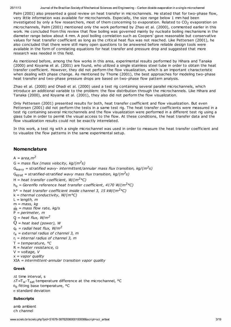
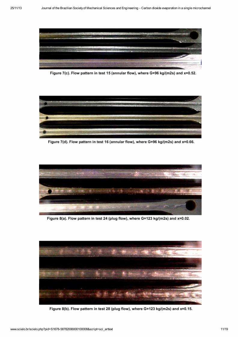
Flow visualization results for 28 tests are given in Figs. 6 to 11. Multiple photographs were taken at differenttimes for each test while measurements were being conducted. In all these figures CO2 flows from the right to
the left. Using the flow regimes described by Carey (1992), three types of flow patterns were observed, namelyplug, slug, and annular flow. Annular flow was assumed to be the regime when no bubbles were observed in the
flow. All patterns were observed for the smaller values of mass flux (up to 149 kg/(m2s)); plug flow waspredominant for low qualities (up to about 0.25); slug flow was predominant for intermediate qualities (from about0.25 to 0.50), and annular flow was observed for high qualities (above 0.50). For mass flux of 188 and 235
kg/(m2s), only two flow patterns could be observed: slug and annular flow. Slug flow was predominant for lowqualities (up to about 0.25) and annular flow was observed for high qualities. The same tendencies and flowpatterns were observed by Pettersen (2001). The visualization results for annular flows were not all much clear.The decision favorable to this flow pattern in some tests was made when no bubble was detected in the flow andsome wavelike form appeared on the pictures. Table 4 presents a summary of the flow regimes.

25/11/13 Journal of the Brazilian Society of Mechanical Sciences and Engineering - Carbon dioxide evaporation in a single microchannel
www.scielo.br/scielo.php?pid=S1678-58782006000100008&script=sci_arttext 10/19
25/11/13 Journal of the Brazilian Society of Mechanical Sciences and Engineering - Carbon dioxide evaporation in a single microchannel
www.scielo.br/scielo.php?pid=S1678-58782006000100008&script=sci_arttext 11/19

25/11/13 Journal of the Brazilian Society of Mechanical Sciences and Engineering - Carbon dioxide evaporation in a single microchannel
www.scielo.br/scielo.php?pid=S1678-58782006000100008&script=sci_arttext 12/19

25/11/13 Journal of the Brazilian Society of Mechanical Sciences and Engineering - Carbon dioxide evaporation in a single microchannel
www.scielo.br/scielo.php?pid=S1678-58782006000100008&script=sci_arttext 13/19

25/11/13 Journal of the Brazilian Society of Mechanical Sciences and Engineering - Carbon dioxide evaporation in a single microchannel
www.scielo.br/scielo.php?pid=S1678-58782006000100008&script=sci_arttext 14/19

25/11/13 Journal of the Brazilian Society of Mechanical Sciences and Engineering - Carbon dioxide evaporation in a single microchannel
www.scielo.br/scielo.php?pid=S1678-58782006000100008&script=sci_arttext 15/19

25/11/13 Journal of the Brazilian Society of Mechanical Sciences and Engineering - Carbon dioxide evaporation in a single microchannel
www.scielo.br/scielo.php?pid=S1678-58782006000100008&script=sci_arttext 16/19
The flow patterns observed in the visualization tests were plotted in Fig. 12 on the flow pattern map developedby Thome and Hajal (2002). This map predicts flow pattern data for seven different refrigerants (not including the
CO2) covering a wide range of mass velocities (10 to 500 kg/m2s), vapor qualities (0.01 to 0.99), and saturation
pressures (about 0.1 to 0.9 MPa). An important characteristic of this map is that it is valid for both adiabatic anddiabatic (evaporating) flows.

25/11/13 Journal of the Brazilian Society of Mechanical Sciences and Engineering - Carbon dioxide evaporation in a single microchannel
www.scielo.br/scielo.php?pid=S1678-58782006000100008&script=sci_arttext 17/19
In Fig. 12 the dashed lines were obtained using G=235 kg/(m2s) while the continuous lines were plotted utilizing
G=58 kg/(m2s). As can be seen in this figure, the flow pattern map proposed by Thome and Hajal (2002) predictsreasonably well the flow patterns obtained for the CO2 evaporation in the microchannel. However, the transition
between intermittent flow and annular flow seems to be over predicted on the Thome-Hajal map. It is worthnoting that the Thome-Hajal map was tested for tube diameters of 8 and 14 mm, which are much higher than thehydraulic diameter of the microchannel. Therefore, the use of this map for the CO2 evaporation in the
microchannel may not be suitable.
Summary and Conclusion
An experimental study of CO2 evaporation inside a 0.8 mm-hydraulic diameter microchannel is presented in this
work. The average heat transfer coefficient along the microchannel was measured and visualization of the flowregimes was conducted. A total of 67 tests were performed at saturation temperatures around 23.3°C for one
heat flux of 1800 W/(m2°C). Vapor qualities ranged from 0.005 to 0.88 and mass flux ranged from 58 to 235
kg/(m2s). An average heat transfer coefficient of 9700 W/(m2°C) with a standard deviation of 35% was obtained.The high data scattering did not permit identify a clear dependency of the heat transfer coefficient with the massflux, as well as with the vapor quality, which seems to characterize nucleate boiling regime for the test
conditions. The correlation for nucleate boiling proposed by Gorenflo (1993), with ho=4170 W/(m2°C), resulted in
h=8320 W/(m2°C), and it was the best comparison to the experimental average result. The dryout of the flow,characterized by the sudden reduction in the heat transfer coefficient, was identified at vapor qualities around0.85. Flow visualization results showed three flow regimes. For low vapor qualities (up to about 0.25), plug flowwas predominant, while slug flow occurred at moderated vapor qualities (from about 0.25 to 0.50). Annular flowwas the flow pattern for high vapor qualities (above 0.50).
References
Aldana, J.P., 2000 "Critical Heat Flux of CO2 in a Microchannel at Elevated Subcritical Pressures", MS Thesis,
University of Illinois at Urbana-Champaign, Urbana-Champaign, IL, USA, 116p. [ Links ]
Bandarra Filho, E.P. 1997 "Study of Convective Boiling Heat Transfer of Halogened Hydrocarbones Refrigerants inHorizontal Tubes" (In Portuguese), MS Thesis, School of Engineering at São Carlos, University of São Paulo, SãoCarlos, SP, Brazil, 139 p. [ Links ]
Bandarra Filho, E.P. 2002 "An Experimental Study of Convective Flow Boiling of Refrigerants Inside Smooth and

25/11/13 Journal of the Brazilian Society of Mechanical Sciences and Engineering - Carbon dioxide evaporation in a single microchannel
www.scielo.br/scielo.php?pid=S1678-58782006000100008&script=sci_arttext 18/19
Microfin Tubes" (In Portuguese), Ph.D. Thesis, Engineering School of São Carlos, University of São Paulo, SãoCarlos, SP, Brazil, 258 p. [ Links ]
Borishanski, V.M., 1969, "Correlation of the Effect of Pressure on the Critical Heat Flux and Heat Transfer RatesUsing the Theory of Thermodynamic Similarity", in Problems of Heat Transfer and Hydraulics of Two-Phase Media,Ed. S.S. Kutateladze, pp. 16-37, Pergamon. [ Links ]
Bredesen, A.M., Hafner, A., Pettersen, J., Neksa, P., Aflekt, K., 1997, "Heat Transfer and Pressure Drop for In-tube Evaporation of CO2", International Conference on Heat Transfer Issues in Natural Refrigerants, College Park,
MD. [ Links ]
Carey, V.P., 1992, "Liquid-Vapor Phase-change Phenomena: An Introduction to the Thermophysics of Vaporizationand Condensation Processes in Heat Transfer Equipment", Hemisphere Publishing Co. [ Links ]
Cavallini, A., 1996, "Working Fluids for Mechanical Refrigeration", Invited paper presented at the 19th InternationalCongress of Refrigeration, The Hague, August 1995, International Journal of Refrigeration, Vol. 19, nº 8, pp. 485-496. [ Links ]
Cooper, M.G., 1984, "Heat Flow Rates in Saturate Nucleate Pool Boiling – a Wide Ranging Examination UsingReduced Properties", Advances in Heat Transfer, Vol. 16, pp. 157-239. [ Links ]
Gorenflo, D., 1993, "Pool Boiling", In: VDI Heat Atlas (chapter Ha). [ Links ]
Hihara, E., and Tanaka, S., 2000, "Boiling Heat Transfer of Carbon Dioxide in Horizontal Tubes", PreliminaryProceedings of the IIR Gustav Lorentzen Conference on Natural Working Fluids, Purdue University, W. Lafayette,IN, USA, July, pp. 279-284. [ Links ]
Hogaard Knudsen, H. J., Jensen, P.H., 1997, "Heat Transfer Coefficient for Boiling Carbon Dioxide", IEA/IIRWorkshop on CO2 Technologies in Refrigeration, Heat Pump and Air Conditioning Systems, Trondheim,
Norway. [ Links ]
Jacobi, A.M., Thome, J.R., 2002, "Heat Transfer Model for Evaporation of Elongated Bubble in Microchannels",Journal of Heat Transfer, n 124, p.1131-1136. [ Links ]
Kandlikar, S.G. 1990, "A General Correlation for Saturated Two-Phase Flow Boiling Heat Transfer Inside Horizontaland Vertical Tubes", Journal of Heat Transfer. Transaction of the ASME, v. 112, p. 219-228. [ Links ]
Koyama, S., Kuwahara, K., Shinmura, E., and Ikeda, S., 2001, "Experimental Study on Flow Boiling of CarbonDioxide in a Horizontal Small Diameter Tube", IIR Conference on Thermophysical Properties and Transfer Processesof New Refrigerants, October 3-5, Paderborn, Germany. [ Links ]
Moffat, R.J., 1988, "Describing the Uncertainties in Experimental Results", Experimental Thermal and Fluid Science,Vol. 1, pp. 2-17. [ Links ]
Palm, B., 2001, "Heat Transfer in Microchannels", Microscale Thermophysical Engineering, Vol. 5, pp. 155-175. [ Links ]
Pettersen, J., Hafner, A., Skaugen, G., and Rekstad, H., 1998, "Development of Compact Heat Exchangers for CO2
Air-condioning Systems", International Journal of Refrigeration, Vol. 21, nº 3, pp. 180-193. [ Links ]
Pettersen, J. 2001, "Flow Vaporization of CO2 in Microchannels Tubes", Doctor Technicae Thesis. Norwegian
University of Science and Technology. Faculty of Mechanical Engineering. Department of Refrigeration and AirConditioning. 249 pp. [ Links ]
Rieberer, R., 1998, "CO2 as Working Fluid for Heat Pumps", Revised copy of doctoral thesis submitted to the
Faculty of Mechanical Engineering, Graz University of Technology, December. [ Links ]
Sha, M.M. 1982, "Chart Correlation for Saturated Boiling Heat Transfer: Equations and Further Study. ASHRAETransaction, v. 88, n 1, p. 185-196. [ Links ]
Sun, Z., and Groll, E., 2001, "CO2 Flow Boiling in Horizontal Tubes", Ray W. Herrick Laboratories, Purdue
University, Internal Report 229.HL-2001-8, W. Lafayette, Indiana, USA, April. [ Links ]
Thome, J.R., 2002, "On Recent Advances in Modelling of Two-phase Flow and Heat Transfer", Proc. 1st
International Conference on Heat Transfer, Fluid Mechanics and Thermodynamics, 8-10 April, Kruger Park, SouthAfrica, pp. 27-39. [ Links ]
Thome, J.R., 2004, "Boiling in Microchannels: a Review of Experimental and Theory", International Journal of Heatand Fluid Flow, v. 25, p 128-139. [ Links ]
Thome, J.R. and Hajal, J.E., 2002, "Two-phase Flow Map for Evaporation in Horizontal Tubes: Latest Version", 1st
International Conference on Heat Transfer, Fluid Mechanics and Thermodynamics, 8-10 April, Kruger Park, South

25/11/13 Journal of the Brazilian Society of Mechanical Sciences and Engineering - Carbon dioxide evaporation in a single microchannel
www.scielo.br/scielo.php?pid=S1678-58782006000100008&script=sci_arttext 19/19
Africa, pp. 182-188. [ Links ]
Yun, R., Hwang, J.H., Kim, Y.C., and Kim, M.S., 2001, "Evaporation Heat Transfer Characteristics of CarbonDioxide in a Horizontal Smooth Tube", IIR Conference on Thermophysical Properties and Transfer Processes ofNew Refrigerants, October 3-5, Paderborn, Germany. [ Links ]
Yun, R., Kim, Y., Kim, M.S., 2005, 'Convective Boiling Heat Transfer Characteristics of CO2 in Microchannels",
International Journal of Heat and Mass Transfer, v. 48, p. 235-242. [ Links ]
Zhao, Y., Molki, M., Ohadi, M.M., Dessiatoun, S.V. 2000, "Flow Boiling of CO2 in Microchannels", ASHRAE
Transactions: Symposia, Vol. 106, Part 1, pp. 437-445. [ Links ]
Paper accepted October, 2005.
Technical Editor: Aristeu da Silveira Neto.
All the contents of www.scielo.br, except where otherwise noted, is licensed under a Creative Commons AttributionLicense
The Brazilian Society of Mechanical Sciences and Engineering
Av. Rio Branco, 124 - 14. Andar20040-001 Rio de Janeiro RJ - Brazil
Tel.: +55 21 2221-0438Fax: +55 21 2509-7129