journal of mechanical engineering vol si 5(1), 143-155
TRANSCRIPT

Journal of Mechanical Engineering Vol SI 5(1), 143-155, 2018
___________________
ISSN 1823- 5514, eISSN 2550-164X Received for review: 2017-05-26
© 2018 Faculty of Mechanical Engineering, Accepted for publication: 2017-06-08
Universiti Teknologi MARA (UiTM), Malaysia. Published: 2018-01-15
Implementation of Fuzzy Logic System for Motor Motion
Generation Based on Electrooculogram
Nurul Muthmainnah Mohd Noor*, Ya’akub Yusof
Fakulti Kejuruteraan Mekanikal, Universiti Teknologi MARA, UiTM,
Cawangan Pulau Pinang, Kampus Permatang Pauh
Pulau Pinang, Malaysia
Ikhmal Nazmi Khairoll Anuar
Fakulti Kejuruteraan Mekanikal, Universiti Teknologi MARA, UiTM
Shah Alam, Selangor, Malaysia
ABSTRACT
Electrooculography (EOG) is a technique that sensed eye movement based
on recording of the standing cornea-retinal potential that existing between
the cornea and retina. This electrooculography signal is known as
electrooculogram that can be used to control the human machine interface
(HMI) such as a wheelchair motion. The aim of this project was to control
the motor by using EOG signals. The signals of eye movements were
acquired using the EOG circuit. These data were passed to the fuzzy logic
controller that was developed using MATLAB. As a result, the two DC
motors were able to operate according to the rules set of fuzzy logic using the
eye signals as inputs. The limitation of this project was the fuzzy logic
controller rules and the membership functions were developed using
MATLAB and then converted into Arduino coding. The Arduino Mega 2560
acts as the interface between the EOG circuit and DC motors. Then, the fuzzy
logic controller was integrated into Arduino Mega 2560 in order to control
the motion of motor. Besides, there were four (4) subjects, two males and two
female, selected for the EOG data acquisition.
Keywords: Electrooculography, wheelchair, DC motor, Fuzzy Logic
Controller (FLC), rehabilitation purpose.
Introduction

Nurul Muthmainnah Mohd Noor
144
Wheelchair is used by disabled person to help moving from one place to
another place. Most of electric wheelchairs operate using joystick, keyboard
and touch screen. These control require hands to operate, so it is not suitable
for the handicapped and paralyzed person to use it. Thus introducing
rehabilitation aid will allow them to become independent in doing several
activities. The latest rehabilitation aid techniques are Human Machine
Interface (HMI) and Human Computer Interface (HCI). The concept of HMI
is converting signal produced by the human body gestures to control the
electromechanical devices, while HCI uses signal from the human body to
control the cursor movements [1]. There are two medium of controls for HCI
and HMI: non-biosignal and biosignal. The examples of non-biosignal are
tongue control and head movement tracking. Electrooculography and
electromyography are the examples of biosignal. There are many
applications developed to help people with several disabilities such as
videooculography systems or infrared oculography based on the eye position
using a camera [2].
There are several applications using eye movement such as controlling
the electronic devices and rehabilitation aids. Besides, it also can guide and
control the mobile robots using the signals that have been developed. One of
them is a video-based tracking system. This system has a high accuracy, so it
can be used as a communication tool between human and machine [3], [4].
However, this system is an expensive device, so the alternative for the eye-
tracking system is based on the electrooculography. Basically, an EOG
circuit is a low cost device , only used the common electrical components.
Hopefully, this technology will expand and have lots of application in the
future where only a gaze or blink of eye is used for controlling any machine
especially in rehabilatation purpose.
This paper consisted of seven topics include the electrooculography
(EOG) and data acquisition of EOG. The experimental setup and fuzzy logic
controller (FLC) also discusses. Then followed by results and discussion.
The last topic is a conclusion.
Electrooculography (EOG)
Electrooculography is a technique that sensed eye movement based on
recording the standing cornea-retinal potential existing between the cornea
and retina [5]. The EOG values ranges from 0.05 mV to 3.5 mV in human
and linearly proportional to eye displacement [6], [7]. It has the range of
frequency about 100Hz in direct current (DC) and changes approximately
0.02 mV for each degree of eye movement [10]. The EOG technique is
inexpensive, easy to use, reliable and relatively unobtrusive compared with

Impl. of Fuzzy Logic System for Motor Motion Generation Based on Electrooculogram
145
head-worn cameras that used in video-based mobile robots such as VOG [8].
The electrooculogram is acquired using five (5) electrodes that placed on the
face as shown in Figure 1. The reference is an important to create safety
electrical path off and also to protect the amplifier [9]. The horizontal
position consists of left and right electrodes whereas vertical position consists
of up and down electrodes [10], [11]. Table 1 shows the eye signal reflected
for vertical and horizontal positions. Since the EOG signal is smaller, it needs
to be amplified using operational amplifier such as AD620 [12]. This signal
then needs to be converted using analog to digital converter such as Arduino
Uno microcontroller and AT90USBKEY based on the ATMEL 8-bit
AT90USB1287 microcontroller [13]. Most the converted signal is processed
using MATLAB. The signal can be used to control the wheelchair motion by
using microcontroller such as PIC 16F877 and LPC1788 [14].
Figure 1: Electrode placement
Table 1: The eye signal reflected
Electrode Position Signal Reflected
A Left
B Right
C Up
D Down

Nurul Muthmainnah Mohd Noor
146
Experiment setup
Figure 2: Experiment setup for acquaring EOG signal
In this experiment, the EOG data acquisition was acquired using Ag/AgCl
electrodes. Figure 2 shows the experiment setup for EOG data acquisition.
The EOG circuit was interfaced with Arduino Mega 2560 that acted as
analog to digital converter. There were four (4) subjects, two males and two
females, who were selected in order to get the data acquisition. The system
was connected with the real motor in order to obeserve the effectiveness of
the proposed control algorithm.
EOG Data Acquisition
The EOG circuit is made from Bio Medical Simple Kit series EOG (JUH
CO., Ltd.) as shown in Figure 3. The gain in this instrumentation amplifier
was 50. The high pass filter was 0.01 Hz with first amplifier with gain of 4.
The notch filter was 60 Hz whereas the band pass filter for low pass filter and
high pass filter were 40 Hz and 0.01 Hz. The gain for second amplifier are
20. The function of the first and second amplifier in this circuit was to
increase the signal amplitude as EOG signal is too small. The total amplifier
or gain in this EOG circuit is 4000. The function of high pass filter and low
pass filter was to reject the noise that amplified by INA126. The function of
notch filter was to cut off frequency of 60 Hz noise.

Impl. of Fuzzy Logic System for Motor Motion Generation Based on Electrooculogram
147
Figure 3: Block diagram of EOG circuit
Meanwhile, Figure 4 shows the EOG horizontal signal acquired using
EOG circuit. It consisted of right and left EOG signals.
Figure 4: EOG Horizontal Signal
The averaged value of EOG horizontal signals were shown in Table 2
and Table 3 for right and left movement of eyes. These readings were taken
from the four subjects calculated from Equation (1). Subject 1 and Subject 2
are males meanwhile Subject 3 and Subject 4 are females. There are five (5)
readings were taken for every subject. In this project, the signal value from
bit number (in digital) was converted into micro-voltage (µV) (in analog)
using Equation (2).

Nurul Muthmainnah Mohd Noor
148
5
readings of 5th)4th3rd2nd(1stAverage
(1)
4000
V 5x 255
Value Signal
Voltage (2)
Table 2: Averaged value of EOG horizontal signals for right movement
Subject Reading (µV) Average
(µV) 1st 2nd 3rd 4th 5th
1 581.91 398.80 189.28 21.51 39.53 246.21
2 133.71 63.59 307.33 428.51 143.25 215.28
3 149.69 83.21 52.49 212.58 33.84 106.36
4 283.07 341.62 335.12 371.03 401.43 346.39
Table 3: Averaged value of EOG horizontal signals for left movement
Subject Reading (µV) Average
(µV) 1st 2nd 3rd 4th 5th
1 657.53 802.86 844.59 871.89 881.96 811.77
2 849.92 896.02 710.26 926.47 994.26 875.39
3 629.18 726.39 622.76 625.24 828.29 686.37
4 735.37 678.33 594.92 573.38 577.91 631.98
From Table 2 and Table 3, the minimum and maximum voltage for
the left eye movement was 106.36 µV and 346.39 µV. While the minimum
and maximum voltage for the right eye movement was 631.98 µV and 875.39
µV. Based on these reading, it say to every person has their own reading of
eye muscles, so that, the algorithm can generate using the minimum and
maximum value. However, in this project, these analog values of EOG signal
were converted into digital value, so that it could be used as the inputs for the
fuzzy logic system using Equation (3).
4000 x 255 x 5V
VoltageValue Digital (3)
Algorithm for Motor Motion Figure 5 shows the algorithm for the motor motion system. The user can
chose the condition either to move in linear direction or angular direction.

Impl. of Fuzzy Logic System for Motor Motion Generation Based on Electrooculogram
149
This condition was displayed on the liquid crystal display (LCD). If the user
chooses to move in linear motion, the eye’s user should look to the left and
then the linear condition will be displayed on LCD. However, in linear
motion, the user has two conditions, either to move forward (FWD) or
reverse (REV). The user was allowed to select any condition within 15
seconds before it looping back to the main menu. The user would move
forward when he/she looking on the right and moving backward when he/she
looking on the left. This condition was same for the angular motion. The user
has 15 second before it looping back to the main menu. The user would move
to the left when he/she looking to the left and to the right when he/she
looking to the right
Figure 5: Algorithm of EOG wheelchair controller

Nurul Muthmainnah Mohd Noor
150
Fuzzy Logic Controller (FLC)
The Sugeno fuzzy inference was used in this project because of constant
output membership function compared with Mamdani fuzzy inference that
have variable of output membership function such as triangular or singleton.
The purpose of this fuzzy logic controller was to fuzzified the EOG signals
into fuzzy variables. This fuzzy input would be deffuzified using weighted
average method into crisp value. The rules was defined from EOG inputs
based on the principle as shown in Table 4.
Table 4: Working principle
Eye movement Preference
If eye is moving Preference is depend on eye movement
direction. The input from Ag/AgCl sensor
will control the motor motion.
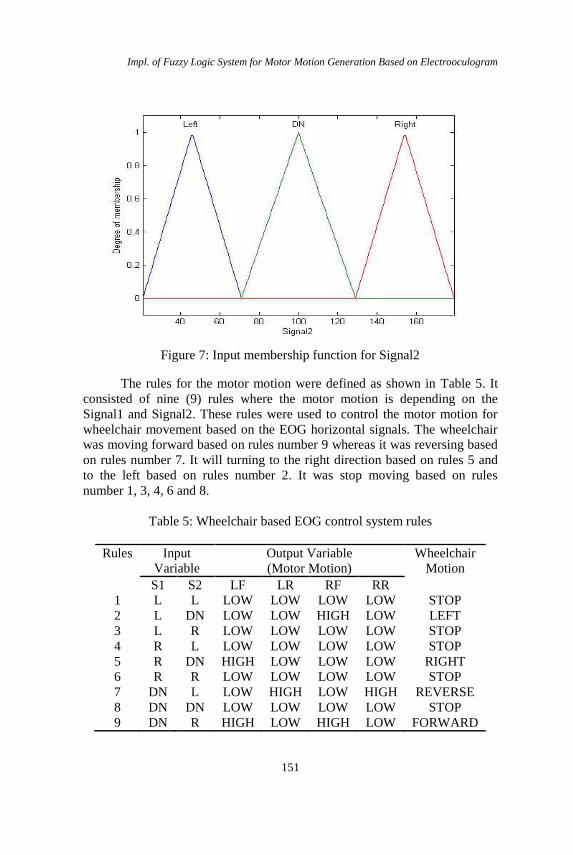
The triangular membership function was used for both input variables
which is Signal1 and Signal2 as shown in Figure 6 and Figure 7. This
membership function is simple, only required three points to forming a
triangle. It consists of three membership functions which were Left, DN (Do
Nothing) and Right. The range input for Left and Right for both input
membership functions were 21 to 71 and 129 to 179 whereas for DN was 71
to 129.
Figure 6: Input membership function for Signal1
Impl. of Fuzzy Logic System for Motor Motion Generation Based on Electrooculogram
151
Figure 7: Input membership function for Signal2
The rules for the motor motion were defined as shown in Table 5. It
consisted of nine (9) rules where the motor motion is depending on the
Signal1 and Signal2. These rules were used to control the motor motion for
wheelchair movement based on the EOG horizontal signals. The wheelchair
was moving forward based on rules number 9 whereas it was reversing based
on rules number 7. It will turning to the right direction based on rules 5 and
to the left based on rules number 2. It was stop moving based on rules
number 1, 3, 4, 6 and 8.
Table 5: Wheelchair based EOG control system rules
Rules Input
Variable
Output Variable
(Motor Motion)
Wheelchair
Motion
S1 S2 LF LR RF RR
1 L L LOW LOW LOW LOW STOP
2 L DN LOW LOW HIGH LOW LEFT
3 L R LOW LOW LOW LOW STOP
4 R L LOW LOW LOW LOW STOP
5 R DN HIGH LOW LOW LOW RIGHT
6 R R LOW LOW LOW LOW STOP
7 DN L LOW HIGH LOW HIGH REVERSE
8 DN DN LOW LOW LOW LOW STOP
9 DN R HIGH LOW HIGH LOW FORWARD

Nurul Muthmainnah Mohd Noor
152
*S1 = Signal1, S2 = Signal2, LF = Left Forward, LR = Left Reverse, RF =
Right Forward, RR = Right Reverse, L = Left, R = Right, DN = Do Nothing
Results and Discussions
In this project, the signal from horizontal position: leftward and rightward
direction were used as an input. The minimum and maximum value for the
left and right eye movement were converted from the voltage (µV) into the
digital value as shown in Table 6.
Table 6: Digital value for eye movement
Eye Movement Minimum (bit) Maximum (bit)
Left 21 71
Right 129 179
The purpose of this value was converted into the digital value due to
use in the fuzzy logic controller. The fuzzy logic controller was developed
and tested using MATLAB/SIMULINK. Figure 8 shows the block diagram
of the fuzzy logic controller. The block diagram consisted of two inputs
which are Signal1 and Signal2. It was also consisted of four (4) outputs
which were LeftForward (LF), LeftReverse (LF), RightForward (RF) and
RightReverse (RR).
Figure 8: Block Diagram of Fuzzy Logic Controller

Impl. of Fuzzy Logic System for Motor Motion Generation Based on Electrooculogram
153
In this project, there were two conditions for the motor motion either
linear motion or angular motion. Table 7 shows the conditions for both linear
and angular motion.
Table 7: Linear and angular condition
No Conditions Signal Value(bit)
1 The main menu display condition to the
user either to move in linear or angular
direction.
Linear : 21 to 71
Angular : 129 to 179
2 The sub menu for linear direction is
display when the user moves the eye to
the left direction.
Forward : 129 < Signal2 <
179 and 71 < Signal1 <
129
Reverse: 21 < Signal2 < 71
and 71 < Signal1 < 129
3 The sub menu for angular direction is
display when the user moves the eye to
the right direction.
Right: 129 < Signal1 < 179
and 71 < Signal2 < 129
Left: 21 < Signal1 < 71
and 71 < Signal2 < 129
The main result for this projects, focused on the motion of motor. There were two motors used in this experiment which were attached on the wheels. Based on the algorithm and fuzzy logic controller, the motors were moved based on the rules. For example, if S1 was L (Left) and S2 was DN (Do Nothing), both motors wouls turn leftward. The summary of the motion of motor can be seen in Table 8.
Table 8: The wheelchair motion based on eye condition
Eye Signal State Result
(Motion) S1 S2 LF LR RF RR
L DN 0 0 1 0 LEFT
R DN 1 0 0 0 RIGHT
DN L 0 1 0 1 REVERSE
DN R 1 0 1 0 FORWARD
DN DN 0 0 0 0 STOP
*S1 = Signal1, S2 = Signal2, LF = Left Forward, LR = Left Reverse, RF =
Right Forward, RR = Right Reverse, L = Left, R = Right, DN = Do Nothing

Nurul Muthmainnah Mohd Noor
154
Conclusion
In conclusion, the objective to control the DC motor motion by using EOG
signals was achieved. The motion of DC motor was depended on the option
selected by the user. Then the fuzzy logic controller can be implemented as a
controller for this system. It is recommended in the EOG data acquisition, the
lead wires should be twisted and not shake as possible to minimize the effects
of external noise. Therefore, the eye signals can be used as a communication
tools such as wheelchair, prosthetic limb and human machine interface.
References [1] C. Biswajeet Champaty, J. Jobin, P. Kunal Pal and A. Thirugnanam,
“Development of EOG Based on Human Machine Interface Control
System for Motorized Wheelchair”, Annual International Conference on
Emerging Research Areas: Magnetics, Machines and Drives, pp 1 – 7
(2014).
[2] A.B. Usakli and S. Gurkan. “Design of a novel efficient human –
computer interface: An electrooculagram based virtual keyboard”,
IEEE Transactions on Instrumentation and Measurement, 59(8), 2099–
2108 (2010).
[3] B. Estrany, P. Fuster, A. Garcia, and L. Yuhua, “EOG signal processing
and analysis for controlling computer by eye movements”, Proceedings
of the 2nd international conference on pervasive technologies related to
assistive environments, p. 18 (2009).
[4] B. Rafael, B. Luciano, J. M. Rodriguez-Ascariz, O. Sergio, and L. Elena,
“Sensory system for implementing a human-computer interface based on
electrooculography”, Sensors, 11(1),310–328 (2010).
[5] B. Rafael, B. Luciano, M. Manuel, and L. Elena, “System for Assisted
Mobility Using Eye Movements Based on Electrooculography”, IEEE
Trans. on Neural Systems and Rehab. Engineering, Vol.10, 209 – 218
(2002).
[6] R. Barea, L. Boquete, L. M. Bergesa, E. Lopez and M. Mazo, “Electro-
Oculographic Guidance of a Wheelchair Using Eye Movements
Codification”, The International Journal of Robotics Research , Vol. 22,
No. 7–8, pp. 641-652 (2003),
[7] Barea R., Boquete L., Ortega S., López E., Rodríguez- Ascariz J.M.,
"EOG-based eye movements codification for human computer
interaction", Expert Systems with Applications, Elesevier, Vol 39, 2677-
2683 (2012).

Impl. of Fuzzy Logic System for Motor Motion Generation Based on Electrooculogram
155
[8] S. Uzma, and A.N Shaikh, “An Overview of Electrooculography”,
International Journal of Advanced Research in Computer and
Communication Engineering, Vol. 2, 4328–4330 (2013).
[9] M. N. N. Muthmainnah and A. Salmiah, “Analysis of different level of
EOG signal from eye movement for wheelchair control”. International
Journal of Biomedical Engineering and Technology, 11 (2). pp. 175-196
(2013).
[10] Zhang X., Sugi T., Wang X., Nakamura M., "Real-time estimation
system of the gaze position based on an electrooculogram", Artificial
Life and Robotics, Vol 14 (2), pp 182-185(2009).
[11] R.Barea, L. Boquete, M. Mazo, E. López, and L. M. Bergasa,”
E.O.G.guidance of a wheelchair using neural networks”. Proceedings.
15th International Conference on Pattern Recognition, Volume 4, 668-
671 (2000).
[12] B. Anwesha, K. Amit, D.N. Tibarewala, R. Janarthanan, “Detecting Eye
Movement Direction from Stimulated Electro-oculogram by Intelligent
Algorithms”, Procedia Technology, Volume 10, 67-75 (2013).
[13] V. Acuna, P. Aqueveque, E. J. Pino, “Eye-Tracking Capabilities of Low-
Cost EOG System”, Engineering in Medicine and Biology Society
(EMBC), 2014 36th Annual International Conference of the IEEE, 610 –
613 (2014).
[14] A. Lopez, I. Rodriguez, F.J. Ferrero, M. Valledor, J.C. Campo, “Low-
Cost System Based on Electro-oculography for Communication of
Disabled People”, IEEE 11th International Multi-Conference on
Systems, Signals & Devices, 1 – 6 (2014).