journal of mechanical engineering vol 16(2), 129-144, 2019
TRANSCRIPT
Journal of Mechanical Engineering Vol 16(2), 129-144, 2019
___________________
ISSN 1823- 5514, eISSN 2550-164X Received for review: 2019-05-02
© 2018 Faculty of Mechanical Engineering, Accepted for publication: 2019-05-12
Universiti Teknologi MARA (UiTM), Malaysia. Published: 2019-08-31
Smart Factory Reference Model for Training on Industry 4.0
Ubaidullah Mohammad
Advanced Technology Training Centre Shah Alam, Malaysia
Cheng Yee Low*, Ramhuzaini Abd Rahman,
Muhammad Akmal Johar, Ching Theng Koh
Universiti Tun Hussein Onn Malaysia
*E-mail: [email protected]
Roman Dumitrescu, Martin Rabe, Laban Asmar
Fraunhofer Institute for Mechatronic Systems Design, Germany
Susana Kamaruddin
SIRIM Berhad, Malaysia
ABSTRACT
Technological disruption and rising labour costs are impacting the future of
manufacturing in Malaysia and its competitive position. Nevertheless, the
understanding on smart manufacturing in the context of Industry 4.0 is still
lacking in the academia and industry. Thus, this work describes the
development of a smart factory reference model as a guide to upgrading an
existing production system towards the vision of Industry 4.0 using readily
available components. The reference model consists of (i) a principle solution
describing the concept of a smart factory and (ii) a working prototype
demonstrating the functionality of a smart factory. The smart factory prototype
is a modular production system connected to a server accessible locally or
through the internet and able to produce up to eight variants of a product. The
SCADA software was used to interface various systems together and create the
user interface. The prototype was evaluated using VDMA Industry 4.0
Toolbox. This work provides a way to integrate theory and practical Industry
4.0 applications into tertiary education curricula. It showcases the potential
applications, benefits and proof of concept of new technologies for industry
adoption.
Keywords: Industry 4.0, Smart Factory, SCADA, Industry IoT, Systems
Engineering
Ubaidullah Mohammad, Cheng Yee Low, et al
130
Introduction
Technological disruption brought by the Internet and digitalization has
influenced our daily routine not just socially but also economically [1]. The
next revolution in the industrial world is driven by the Internet and
Communication Technology (ICT), thus Industry 4.0 is introduced as one of
the German strategic initiatives to establish Germany as the market leader and
provider of advanced manufacturing solutions [2]–[4]. It is said to be the fourth
revolution in the industrial world after the previous industrial revolutions of
steam power-mechanization, electricity-mass production line, and computer-
automation. Industry 4.0 also can be interpreted as a cyber-physical system in
which advanced manufacturing, automation and ICT are linked together and
connected to the Internet [3]–[6].
Among the applications of Industry 4.0 is a smart factory. Smart factories
are interconnected, highly automated and intelligent. Information technology
plays a vital role in interconnecting standalone automated systems so that they
could communicate and transfer data between each other especially through
the Internet [6].
In this work, a reference model for a smart factory, as shown in Figure 1,
has been developed. The reference model consists of a principle solution and
a prototype. On one hand, the principle solution describes a system model and
how the system elements are interconnected. On the other hand, the prototype
demonstrates the operation of the smart factory. Such a model is needed to
enable an intuitive understanding of the concept of smart factory in the context
of Industry 4.0.
Figure 1: The smart factory reference model consists of (i) a principle
solution describing the concept of a smart factory and (ii) a prototype
demonstrating the operation of the smart factory.
Smart Factory Reference Model for Training on Industry 4.0
131
Motivation
In contrast to the previous industrial revolutions which were defined after it
took place, Industry 4.0 is being defined while it is taking place. Thus, the
fundamentals, architecture and methodologies for Industry 4.0 are still
emerging [7]–[9]. Although several solution providers are currently
developing the solutions, high capital investment is often required [10]. In
2018, the national policy on Industry 4.0 was launched by the Prime Minister
of Malaysia [11]. The government of Malaysia has announced to providing
support to prepare Malaysia for the era of Industry 4.0. Government agencies
have been tasked to enable the required infrastructure and ecosystem, funding
and incentives, talent and human capital, technology and standards, and SMEs
facilitation.
It is a challenge for training institutes, i.e. technical universities and TVET
institutions in Malaysia, to train future workforces with the necessary skills
and competency required in the era of Industry 4.0. Without a reference model,
it is hard to evaluate the feasibility of a smart factory. It must come at a
reasonable cost [12]. In most cases, high upfront investment is unaffordable by
industries and training institutes in Malaysia. To supplement these
developments, a reference model utilizing off the shelf components to evaluate
the feasibility of a smart factory of Industry 4.0 and to train students and
workers is desperately needed. One of the solutions is to upgrade or convert an
existing system with Industry 4.0 elements. The challenges include the
identification of the Industry 4.0 elements that can be integrated into an
existing system and also how to interface these various devices and
components, and connect it to the Internet.
Smart Factories in the era of Industry 4.0
Factories around the world are transforming and becoming smarter with the
implementation of automation system throughout the factory. Components and
devices on a production floor will be interconnected with one another [3]. It
will also be connected to various other systems such as the facility
management system and other departments such as logistics, and maintenance.
In this manner, data could be exchanged between various systems and
department making operations smoother and more efficient [13]. By
connecting to the internet, production control and monitoring could be done
outside of the factory compound [14].
Another criterion of a smart factory is the flexibility or modularity of
the manufacturing system [7][14]. Manufacturers have to satisfy the target
consumers group which would have different needs. While doing this, the price
must still be competitive which is hard to be achieved with too many product
variations [15]. Therefore a production line must be easily modified to suit the

Ubaidullah Mohammad, Cheng Yee Low, et al
132
product that it will be manufacturing [2]. The product itself will be designed
so that it could be modular, manufactured using common manufacturing
processes and customizable. Parameters of the machine or the specification of
the product are kept, for instance, in a radio-frequency identification (RFID)
tag [7], or even in cloud storage. Therefore, if parameters of the machines or
specification of products have to be changed, this could be done through the
internet without reprogramming the controller. Smart factories are equipped
with various sensors used to collect data that will be used for monitoring and
analysis. Advanced sensors are installed throughout the whole production line
in order for the machines to make certain decisions [16]. It also implements a
decentralized control strategy in which each production station comes with its
own controller.
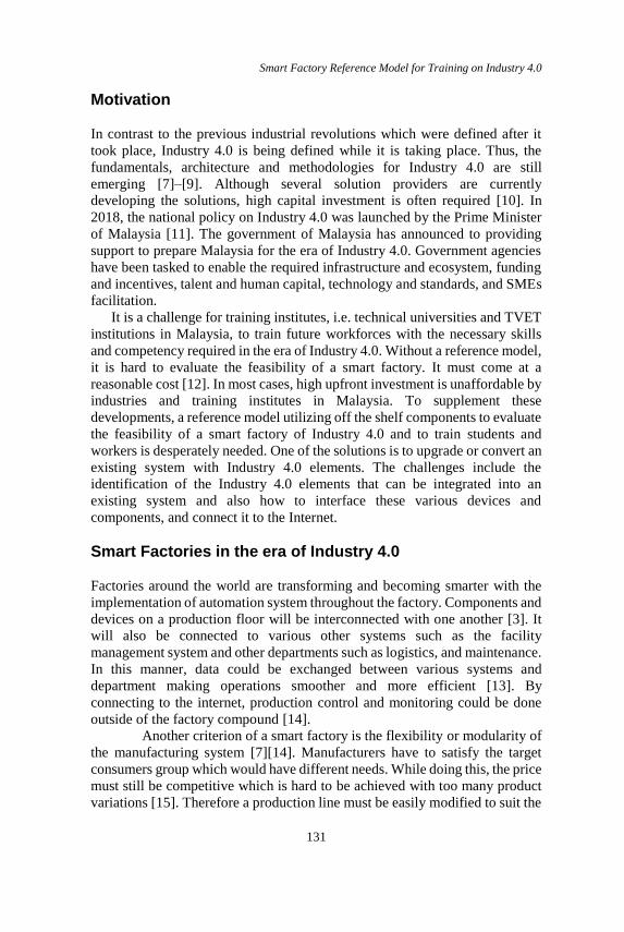
Specification of Principle Solution
The principle solution is described using the specification technique
CONSENS [17][18] or CONceptual design Specification technique for the
ENgineering of complex Systems. Such a principle solution is illustrated in the
upper part of Figure 2. It comprises six aspects of a smart factory, i.e.,
environment, application scenarios, requirements, functions, active structure
and behaviour.
The lower part of Figure 2 exemplifies the active structure for a smart
factory. It shows all the internal and external system elements of the smart
factory as well as the interconnection between the system elements in terms of
material flow, energy flow and information flow. The server hosts a database
and a supervisory control and data acquisition (SCADA) software is used to
create the user interface. This interface can be accessed locally or remotely.
With this, the user does not necessarily need to be in the factory to interact
with the system. The same interface is used not only by the production team
but also by the other users, from the customer to the sales and maintenance
personnel. A router is used as a gateway to the Internet. Each main element of
the system and the server has its own static IP which is managed by the router.
The system is mainly connected using an Ethernet connection using various
protocols. In this production system, two energy sources are used which are
electrical power and pneumatic power. Electrical power is used to power up
all the electrical/electronic components and pneumatic power is used to actuate
the pneumatic components.
Smart Factory Reference Model for Training on Industry 4.0
133
Figure 2: Cut-out from the active structure describes the system level
architecture for a smart factory.

Ubaidullah Mohammad, Cheng Yee Low, et al
134
Development of Smart Factory Prototype In this section, the product that will be manufactured as well as the hardware
and software of the smart factory prototype are described.
Product description
In this prototype, eight variants of product could be manufactured using the
same production line without reprogramming effort. The idea is to demonstrate
the configuration of common product items to create a combination of choices
according to the customer preferences. The product consists of three main
elements, i.e., a cylinder case, an infill and a cap. Figure 3 describes the eight
variants of the product that can be selected by the customers. Two colour
options (black or red) are available for the case and the cap. Similarly, there
are two different infills (I1 or I2) to be chosen. For the purpose of product
variants identification, an RFID tag is attached at the bottom of the cylinder
case.
Variants Case Cap Infill
V1 Black Black I1
V2 Black Black I2
V3 Black Red I2
V4 Black Red I1
V5 Red Red I1
V6 Red Red I2
V7 Red Black I2
V8 Red Black I1
Figure 3: Configuration of the manufactured product.
Hardware development
A prototype has been developed to demonstrate the workability of the smart
factory concept specified in the principle solution. The prototype was set up
by upgrading an existing didactic trainer system. It composed of three
production stations built based on a modular and decentralized production
Smart Factory Reference Model for Training on Industry 4.0
135
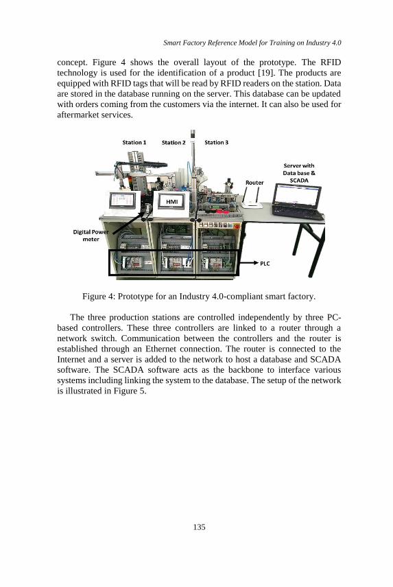
concept. Figure 4 shows the overall layout of the prototype. The RFID
technology is used for the identification of a product [19]. The products are
equipped with RFID tags that will be read by RFID readers on the station. Data
are stored in the database running on the server. This database can be updated
with orders coming from the customers via the internet. It can also be used for
aftermarket services.
Figure 4: Prototype for an Industry 4.0-compliant smart factory.
The three production stations are controlled independently by three PC-
based controllers. These three controllers are linked to a router through a
network switch. Communication between the controllers and the router is
established through an Ethernet connection. The router is connected to the
Internet and a server is added to the network to host a database and SCADA
software. The SCADA software acts as the backbone to interface various
systems including linking the system to the database. The setup of the network
is illustrated in Figure 5.

Ubaidullah Mohammad, Cheng Yee Low, et al
136
Figure 5: Overall network setup of the smart factory prototype
The first production station which is a “Distributing Module” and is
responsible for separating different colour (black or red) of cylinder cases from
the stack magazines. Then a pneumatic linear drive with a gripper arm is used
to pick and place the cylinder cases. An RFID reader is installed in this station
to identify a tag attached at the bottom of each cylinder case. The RFID reader
is connected to the controller via the RS232 connection. Also, a touchscreen
monitor that acts as Human Machine Interface (HMI) is connected to the
station. The HMI is linked to the controller and thus enable the input/output
components as well as the machine to be visualized.
The second production station is known as a “Processing Module”
and is dedicated to the process of filling the case with infill I1 or I2 as well as
putting the cap. Note that, in this prototype, the process of filling the infill is
just represented by blowing air from two different nozzles. For the capping
process, a gantry module powered by an electric linear drive is employed. The
module picks the caps (black or red) from the cap dispensers by means of
vacuum suction and place it on the cylinder case.
The third production station is a “Sorting Module”. It has the function
to check and sort the good products from the rejected products. Optical sensors
are used to identify the colour of the product and check whether the cap is on
the cylinder case or not. The product is then transported by a conveyor belt to
electro-pneumatic gates for sorting purposes. The products are sorted into two
different slides (Slide 1 and Slide 2) according to the delivery regions. Another
slide, Slide 3, is devoted to the rejected products.
Smart Factory Reference Model for Training on Industry 4.0
137
Software development
The software development involves the programming of the controllers,
development of the system interface and the configuration of the database. The
controllers are programmed using several PLC languages, among others, the
sequence function chart, structured text and ladder diagram. For this purpose,
TwinCAT 2 is used. For the SCADA, Indusoft Webstudio 8.0 is used to create
the user interface displaying various data on the screen, and to carry out a
certain process. The SCADA software is developed to be able to handle
multiple user roles, for example, a customer or an engineer. A customer can
only access the system to order products or check the order status while an
engineer could check the status of the entire production line. A HMI is used as
a control panel and to visualize the input and output signals. The layout is
programmed using PM Designer 2.0. In comparison to using physical control
panels, the usage of graphical user interface offers greater flexibility as it
allows the layout of the interface to be changed or added to accommodate
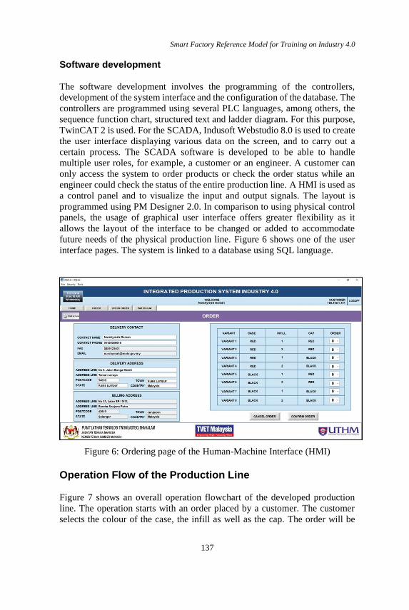
future needs of the physical production line. Figure 6 shows one of the user
interface pages. The system is linked to a database using SQL language.
Figure 6: Ordering page of the Human-Machine Interface (HMI)
Operation Flow of the Production Line
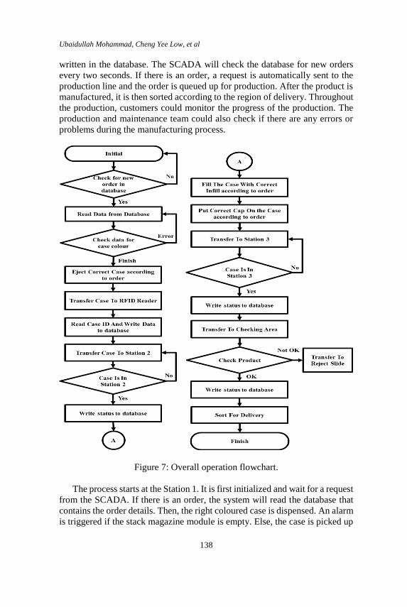
Figure 7 shows an overall operation flowchart of the developed production
line. The operation starts with an order placed by a customer. The customer
selects the colour of the case, the infill as well as the cap. The order will be
Ubaidullah Mohammad, Cheng Yee Low, et al
138
written in the database. The SCADA will check the database for new orders
every two seconds. If there is an order, a request is automatically sent to the
production line and the order is queued up for production. After the product is
manufactured, it is then sorted according to the region of delivery. Throughout
the production, customers could monitor the progress of the production. The
production and maintenance team could also check if there are any errors or
problems during the manufacturing process.
Figure 7: Overall operation flowchart.
The process starts at the Station 1. It is first initialized and wait for a request
from the SCADA. If there is an order, the system will read the database that
contains the order details. Then, the right coloured case is dispensed. An alarm
is triggered if the stack magazine module is empty. Else, the case is picked up

Smart Factory Reference Model for Training on Industry 4.0
139
by a gripper and transports it to the RFID reader. After reading the RFID tag,
the ID is written into the database. Then the case is transported to the next
station. As the production line is running, the customers can check the status
of the orders through the user interface. Engineers, on the other hand, can
monitor the system such as monitoring the IO signals of the stations.
For the Station 2, after the initializing, it will wait for the cylinder case
from Station 1. If a reject signal is received, the case is transferred directly to
Station 3. Else, the station reads data from the database to determine the type
of infill and colour of the cap. The case is then filled with the infill ordered by
the customer. Subsequently, the station dispenses a cap accordingly. The
gantry module picks up the cap and places it on the case. Note that, as long as
the product is still not manufactured and the station has not read the data, the
customer can still modify their order.
Lastly, Station 3 will first wait for the workpiece from Station 2. If a
rejected signal is received, it will be transferred into the third slide or the reject
slide. Otherwise, the product is transported to the checking point in which the
product will be checked. The system checks the colour and whether a cap has
been put on the case or not. Then it will sort the finished product into the
respective slides.
Evaluation using the VDMA Industry 4.0 Toolbox
The smart factory prototype was developed using an existing didactic trainer
system. After retrofitting and upgrade according to the principle solution, a
smart factory prototype has been built. To evaluate the smart factory prototype,
the VDMA Industry 4.0 Toolbox as shown in Figure 8 was used. This toolbox
is used to determine the Industry 4.0 application level of a system [8]. Six
aspects of the system were evaluated and each of the aspects is divided into
five criteria level from level zero to level four. The prototype is evaluated
against the criteria of each level to determine the level it has achieved. The
arrows shows the improvements between one to three levels up in the specific
aspects.
The first aspect is data processing in the production line. Acquisition and
processing of data are one of the fundamentals of Industry 4.0. It starts with
data acquisition until the analysis of data for an automated process planning
and control. This prototype manage to achieve a level one. The system is
connected to SCADA software used for data acquisition from various devices
and is able to connect to a database to store and extract data. The system also
has the capability to display and record the trend of certain parameters for
analysis. For example, it is constantly monitoring the electrical parameters
such as voltage and energy. This system only monitors and display the data
and does not analyse the data it received. But then, the platform for data
analysis is already provided. The acquired data can be analysed by developing
Ubaidullah Mohammad, Cheng Yee Low, et al
140
an algorithm for the analysis function and program it into the devices.
Previously, the system is not connected to any database and therefore rated at
level zero.
The second aspect is the machine to machine communication (M2M).
M2M communication is important for data exchange in an interconnected
system. For this aspect, the prototype manages to obtain a level three. M2M
communication can be done using field bus technology to reduce the wiring
but thus involves data communication which the data need to be encoded and
later decoded. A faster system is to use industrial Ethernet which is able to
connect to more devices and can transfer a larger size of data. This system uses
an Ethernet connection for most of its communication. All of the main
components are connected to a gateway which has Internet access. Here, the
SCADA software acts as the interface for remote access from the Internet
hence this system achieved a level three. Previously, the system was rated at
level one. Depending on the type of communication of the PLCs, it uses field
bus communication for M2M communication.
The third aspect is the company-wide networking with production. This
prototype managed to achieve a level two as it is not really implemented in a
company. The prototype is connected to the main network. Various
information exchange method can be used and can be set in the SCADA
software. The system is able to be accessed by various users from various
departments using the same interface. The SCADA software acts as the main
interface for data exchange between various devices. Previously, the system
was rated at level zero as it was not connected to any network.
The fourth aspect is the infrastructure of information and
telecommunication technologies in production. This aspect focuses on the
connectivity and exchange of data. This system managed to achieve level
three. The prototype is connected to a central server which hosts a database.
Various data such as users and orders details are stored on this server. It could
also be accessed through the Internet. Customers can track their order through
its user interface. Some data are exchanged automatically, for example, when
the system has finished a process, it will update the status of the production on
to the database on the server. Previously, the system was rated at level zero as
there was no connection to any storage server or to the Internet.
The fifth aspect is the human-machine interface. Human must be able to
give orders or to receive information or the status of production from a system.
This prototype has managed to achieve level three. The user of this system
could interact with the system locally using a touch screen HMI on-site or
using the SCADA interface locally or remotely within the network or through
the Internet. The SCADA software also provides a centralized monitoring and
control interface. Previously, the system has only a local interface and was
rated at level one.
Smart Factory Reference Model for Training on Industry 4.0
141
The sixth aspect is the efficiency with small batches. Nowadays, the trend
is leaning towards a more individual, customizable product that is produced in
small batches, or even lot size one. This will lead to a more complex production
process whilst maintaining an affordable price. The integration of ICT in the
production system will help reduce errors in production and increase efficiency
[20]. The prototype has managed to achieve level two. The product produced
by this system uses a modular concept. It uses identical parts but the users
could mix and match these identical parts into variants of their own. The
products are still manufactured using the same production layout and process.
Previously, the system was rated at level zero. It can only produce products in
batches.
Conclusion
In order to understand and to embrace Industry 4.0, a reference model
consisting of a principle solution and a working prototype has been developed
to learn and teach this topic. The model showcases the capabilities of a smart
factory in compliance with Industry 4.0. The prototype has been developed
using off-the-shelf components including PC-based controllers and network
components, thus making it available immediately at an affordable cost
especially to training institutes. With this smart factory model, companies will
be able to conduct a feasibility study and evaluate the concept of Industry 4.0.
In addition, the academia can use this model to train the concept of Industry
4.0 and determine what are the skill sets and competency required for future
engineers in the era of Industry 4.0 so that it could be adopted in the current
curricula.

Ubaidullah Mohammad, Cheng Yee Low, et al
142
Figure 8: Evaluation for the six aspects of the VDMA Toolbox
Smart Factory Reference Model for Training on Industry 4.0
143
Acknowledgement
The authors would like to thank Universiti Tun Hussein Onn Malaysia and
Advanced Technology Training Centre Shah Alam for supporting this
research.
References
[1] Klaus Schwab, “The Fourth Industrial Revolution: what it means, how to
respond,” World Economic Forum, 2016. [Online]. Available:
https://www.weforum.org/agenda/2016/01/the-fourth-industrial-
revolution-what-it-means-and-how-to-respond/. [Accessed: 16-Dec-
2018].
[2] S. Weyer, M. Schmitt, M. Ohmer, and D. Gorecky, “Towards Industry
4.0 - Standardization as the crucial challenge for highly modular, multi-
vendor production systems,” IFAC-PapersOnLine, vol. 48, no. 3, pp.
579–584, 2015.
[3] K. Henning, W. Wolfgang, and H. Johannes, “Recommendations for
implementing the strategic initiative INDUSTRIE 4.0 :Final report of the
Industrie 4.0 Working Group,” 2013.
[4] M. A. K. Bahrin, M. F. Othman, N. H. N. Azli, and M. F. Talib, “Industry
4.0: A Review on Industrial Automation and Robotic,” J. Teknol.
(Sciences Eng., vol. 78, no. 6–13, pp. 137–143, 2016.
[5] W. MacDougall, Industrie 4.0: Smart Manufacturing for the Future.
Germany Trade and Invest, 2013.
[6] C. Toro, I. Barandiaran, and J. Posada, “A perspective on Knowledge
Based and Intelligent systems implementation in Industrie 4.0,” Procedia
- Procedia Comput. Sci., vol. 60, no. 19th International Conference on
Knowledge Based and Intelligent Information and Engineering Systems,
pp. 362–370, 2015.
[7] V. Roblek, M. Meško, and A. Krapež, “A Complex View of Industry
4.0,” SAGE Open, vol. 6, no. 2, pp. 1–11, 2016.
[8] B. Stahl, R. Anderl, and J. Fleischer, “Guideline Industrie 4.0: Guiding
principles for the implementation of Industrie 4.0 in small and medium
sized businesses,” VDMA Verlag GmbH, Frankfurt am Main, 2016.
[9] Martin, “Industry 4.0: Definition, Design Principles, Challenges, and the
Future of Employment,” CLEVERISM, 2017. [Online]. Available:
https://www.cleverism.com/industry-4-0/. [Accessed: 09-Dec-2018].
[10] K. Thoben, S. Wiesner, and T. Wuest, “‘Industrie 4.0’ and Smart
Manufacturing – A Review of Research Issues and Application
Examples,” Int. J. Autom. Technol., vol. 11, no. 1, pp. 4–16, 2017.
[11] Malaysia Ministry of International Trade and Industry, Industry 4WRD :

Ubaidullah Mohammad, Cheng Yee Low, et al
144
NATIONAL POLICY ON INDUSTRY 4.0. Perpustakaan Negara
Malaysia, 2018.
[12] J. Enke, K. Kraft, and J. Metternich, “Competency-oriented design of
learning modules,” Procedia CIRP, vol. 32, no. The 5th Conference on
Learning Factories 2015 Competency-oriented, pp. 7–12, 2015.
[13] D. Kolberg and D. Zühlke, “Lean Automation enabled by Industry 4.0
Technologies,” IFAC-PapersOnLine, vol. 48, no. 3, pp. 1870–1875,
2015.
[14] S. Wang, J. Wan, D. Li, and C. Zhang, “Implementing Smart Factory of
Industrie 4.0 : An Outlook,” Int. J. Distrib. Sens. Networks, vol. 2016,
2015.
[15] F. S. Fogliatto, G. J. C. Da Silveira, and D. Borenstein, “The mass
customization decade: An updated review of the literature,” Int. J. Prod.
Econ., vol. 138, no. 1, pp. 14–25, 2012.
[16] R. Y. Zhong, X. Xu, E. Klotz, and S. T. Newman, “Intelligent
Manufacturing in the Context of Industry 4.0: A Review,” Engineering,
vol. 3, no. 5, pp. 616–630, 2017.
[17] J. Gausemeier, T. Gaukstern, and C. Tschirner, “Systems engineering
management based on a discipline-spanning system model,” Procedia
Comput. Sci., vol. 16, no. Conference on Systems Engineering Research
(CSER’13), pp. 303–312, 2013.
[18] J. Gausemeier, C. Y. Low, D. Steffen, and S. Deyter, “Specifying the
principle solution in mechatronic development enterprises,” 2008 IEEE
Int. Syst. Conf. Proceedings, SysCon 2008, pp. 160–166, 2008.
[19] T. Stock and G. Seliger, “Opportunities of Sustainable Manufacturing in
Industry 4.0,” Procedia CIRP, vol. 40, no. 13th Global Conference on
Sustainable Manufacturing-Decoupling Growth from Resource Use, pp.
536–541, 2016.
[20] S. I. Shafiq, C. Sanin, E. Szczerbicki, and C. Toro, “Virtual Engineering
Object / Virtual Engineering Process : A specialized form of Cyber
Physical System for Industrie 4.0,” Procedia - Procedia Comput. Sci.,
vol. 60, pp. 1146–1155, 2015.