journal of mechanical engineering vol 14(2), 36-48, 2017
TRANSCRIPT

Journal of Mechanical Engineering Vol 14(2), 36-48, 2017
___________________
ISSN 1823- 5514, eISSN 2550-164X Received for review: 2016-06-27
© 2017 Faculty of Mechanical Engineering, Accepted for publication: 2017-04-27
Universiti Teknologi MARA (UiTM), Malaysia. Published: 2017-12-31
The Influence of Steel 35 Wire EDM Parameters on the Surface
Roughness and Morphology
Alexey A. Fedorov
Alexander V. Linovsky
Anatoliy P. Morgunov
Omsk State Technical University (OmSTU), Omsk, Russia
ABSTRACT
The electrical discharge machining (EDM) is a non-traditional machining
method that has been widely used in various industries recently. The two
important EDM performance measures are the surface roughness and the
surface morphology. The research results of the influence of steel 35 wire
EDM parameters, particularly the number of cuts on the surface roughness
and the surface morphology are presented. Using the methods of atomic
force microscopy, scanning electronic microscopy and profilometry, it is
shown that the roughness and morphology of the machined surfaces differs
much from the theoretical one, and has some peculiar characteristics. The
reasons of the difference between practical results and theory are also
described. The main are suggested to be the fast front spreading of a gas
bubble, turbulent eddies formed by the flow of the pumped liquid. Besides, a
crater with a different structure is found and an attempt to explain its nature
is made.
Keywords: Wire-EDM; roughness; surface morphology; steel 35; SEM;
AFM

The Influence of Steel 35 Wire EDM Parameters on The Surface Roughness and Morphology
37
Introduction
The EDM has been used for high precision machining of complex-shape
workpieces made from hard materials. This type of machining was described
by Lazarenko in 1946 [1]. The EDM process is based on the erosive effects
of discharges flowing between the electrodes in liquid dielectric. Successive
electrical discharges occur at high frequencies, and each discharge results in
a tiny crater, both on the tool and on the workpiece surface [2]. This process
produces a cratered surface [3]. Roughness is formed as result of many pulses
as a complex of erosive craters and can be described by the scheme shown in
Figure 1. The form of craters can differ from a theoretical (spherical) one,
and can involve many factors: mainly, the electrodes material, the pulse
duration, the discharge frequency, and the discharge current intensity [4-6].
Therefore, the actual profile formed by a plurality of craters differs
from the theoretical one. The debris on the surface is also possible, which is
normal for the EDM, but can cause differences from the theoretical scheme.
This paper aim is to analyze the influence of steel 35 GOST 1050-88
(analog AISI 1035) wire EDM parameters, and particularly the number of
cuts on the surface roughness and the surface morphology, and to compare
theoretical scheme of the surface morphology formed by sequential cuts
during wire EDM with experimental results. Theoretically, material removal,
as a result of EDM cuts, has the following sequence: after the 1st cut the
surface profile is made of a number of craters with specific radius and depth
(Figure 1a); after the 2nd cut the material is removed from the tops of the
craters appeared after the 1st cut which leads to less rough surface (Figure
1b). If the surface profile presented in Figure 1b is viewed from above, after
two cuts the surface morphology should look like as shown in Figure 1с and
should form a kind of shapes as hexagons and circle elements with step Sx,
Sy. During the third, and the following cuts, the material removal should
have the same sequence. The general image of the surface is made-up by a
number of craters crossing each other, and limited by rims or by bulges. The
formation mechanism of the bulges around the crater is clarified by Yang at
al. [7].
The same scheme about metal surface forming is described in
Serebrenitsky [8]. The author points out the difference between the
theoretical and the experimental data, too.

Alexey A. Fedorov et.al.
38
Figure 1: Theoretical scheme of the surface morphology and the surface
roughness form: a – surface profile after the 1st cut, b – surface profile after
the 2nd cut, c – surface morphology
Methodology
The workpieces were flat samples of 140×50×10 mm constructional steel 35.
The content of the main elements in steel 35 is as follows: С = 0.35 %; Si =
0.21 %; Mn = 0.69 %; Cr = 0.1 %; Ni = 0.15 % (by weight). The workpieces
machining was carried out by EDM machine SODICK VZ300L during the
first, second, third and fourth cut. Deionized water has been used as dielectric
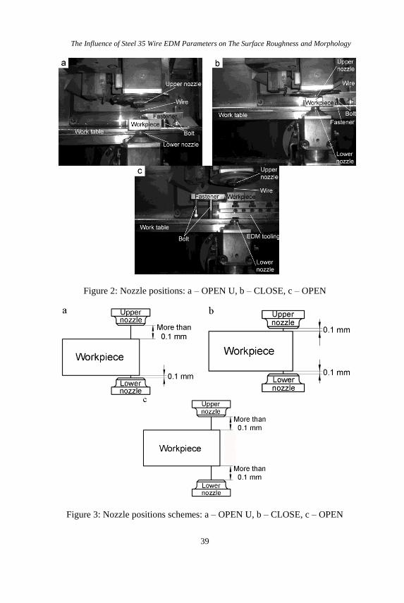
fluid. During the experiment, the nozzles positions were also changed while
machining (Figure 2a – 2c). The schemes corresponding to these positions
are shown in Figure 3a – 3c:
1) OPEN U – one side open clearance machining (lower nozzle is at the
distance of 0.1 mm from the workpiece, upper nozzle is at the distance
of more than 0.1 mm from the workpiece);
2) CLOSE – close-contact machining (both nozzles are at the distance of
0.1 mm from the workpiece).
3) OPEN – open clearance machining (both nozzles are at the distance of
more than 0.1 mm from the workpiece);
The Influence of Steel 35 Wire EDM Parameters on The Surface Roughness and Morphology
39
Figure 2: Nozzle positions: a – OPEN U, b – CLOSE, c – OPEN
Figure 3: Nozzle positions schemes: a – OPEN U, b – CLOSE, c – OPEN

Alexey A. Fedorov et.al.
40
The machining parameters are shown in Table 1. Uav and Iav
calculated by the machine software were monitored by the indication of the
on-board voltmeter and ammeter.
Table 1: Machining parameters
№ of cut Uav, V Iav, А
The first cut 43 12.3
The second cut 70 1.1
The third cut 59 0.8
The fourth cut 15 0.5 Where Uav is the average voltage value; Iav is the average electric current
value.
The study of the surface morphology and roughness was carried out using
three methods: first, the profilometry, performed with the surface roughness
tester TR220; second, atomic force microscopy of the workpieces, carried out
by the NTEGRA Prima scanning probe microscope in the air contact mode,
(the images obtained were analyzed by IMAGE ANALISIS (NT-MDT)
program module); third, scanning electron microscopy, carried out by JEOL
JCM-5700 microscope in high vacuum mode (the signal type was SEI). The
spotsize parameter was changed in the range from 20 to 71, the value of
accelerating voltage was changed in the range 5 – 20 kV, magnification was
in the range from 300× to 11000×.
Results and discussion Workpieces profilograms obtained after cuts 1 – 4 were given in Figure 4a –
4d, correspondently, while obtained values are listed in Table 2.
Table 2: Ra/Rt values after the 1 - 4 cuts
№ of cut Ra1, µm Ra/Rt, µm
The first cut 2.8 3.04/20.21
The second cut 1.8 1.88/14.43
The third cut 0.8 0.53/5.56
The fourth cut 0.4 0.36/2.99

The Influence of Steel 35 Wire EDM Parameters on The Surface Roughness and Morphology
41
a)
b)
c)
d)
Figure 4: EDM-ed surface steel 35 profilograms: a – after the first cut, b –
after the second cut, c – after the third cut, d – after the fourth cut
Where Ra1 is the roughness, stated by a machine manufacturer, i.e.
such surface roughness that should be obtained if steel SKD 11 (HRC 58) is
machined according to SODICK VZ300L manual; Ra/Rt is the real
roughness value obtained by profilometry.
The actual roughness obtained after the machining differs from that
stated by a manufacturer, due to the differences in the chemical composition
of the material. In the machine software there is only one mode for steel,
which can differ significantly in chemical composition from the machined
steel 35 resulting in the described differences. Before the discussion, it is

Alexey A. Fedorov et.al.
42
necessary to note that all the images showed below are taken of the surfaces
machined in the OPEN U mode, which is between “OPEN and CLOSE”
modes positions, and proved to be quite informative.
Figure 5: Morphology of EDM-ed steel 35 surface after the 1st cut obtained
by SEM: a – 300×, b – 1000×, c – amorphised spheres stuck to the surface as
a result of insufficient machining, 1000×
However, it should also be noted that after the first cut (Figure 5) the
surface has a morphology acutely different from that obtained after the
mechanical machining, as well as from the theoretical one obtained after
EDM-ing (Figure 1c). In particular, there is no microrelief regularity formed
by adjacent or crossing craters, possibly, the micro-relief in this case is
formed by craters, but their boundaries are worn down much by the metal
splashed from craters and formed numerous bulges. As the first cut is made
at high-energy mode, the surface varies in height. There are areas sized 50-
100 µm and more, located below the mean line (black spots in Figure 5a).
Besides, there are plenty of details on the surface, looking like swarf and
EDM-debris, which could not be swept away by the fluid, but, on the
contrary, were welded to the surface while being molten. Probably, the
highest peaks in the corresponding profilogram (Figure 4a) are determined by
this swarf and EDM-debris. Metal spheres are detected in Figure 5c. As the
analyses showed, they are different: some spheres 1 are larger, 7.2 – 9.6 µm
The Influence of Steel 35 Wire EDM Parameters on The Surface Roughness and Morphology
43
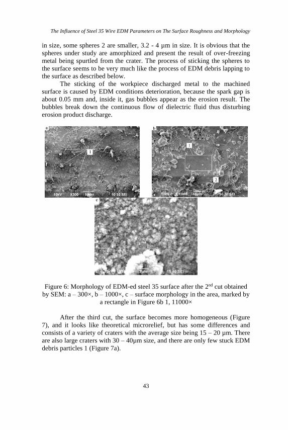
in size, some spheres 2 are smaller, 3.2 - 4 µm in size. It is obvious that the
spheres under study are amorphized and present the result of over-freezing
metal being spurtled from the crater. The process of sticking the spheres to
the surface seems to be very much like the process of EDM debris lapping to
the surface as described below.
The sticking of the workpiece discharged metal to the machined
surface is caused by EDM conditions deterioration, because the spark gap is
about 0.05 mm and, inside it, gas bubbles appear as the erosion result. The
bubbles break down the continuous flow of dielectric fluid thus disturbing
erosion product discharge.
Figure 6: Morphology of EDM-ed steel 35 surface after the 2nd cut obtained
by SEM: a – 300×, b – 1000×, c – surface morphology in the area, marked by
a rectangle in Figure 6b 1, 11000×
After the third cut, the surface becomes more homogeneous (Figure
7), and it looks like theoretical microrelief, but has some differences and
consists of a variety of craters with the average size being 15 – 20 µm. There
are also large craters with 30 – 40µm size, and there are only few stuck EDM
debris particles 1 (Figure 7a).
Alexey A. Fedorov et.al.
44
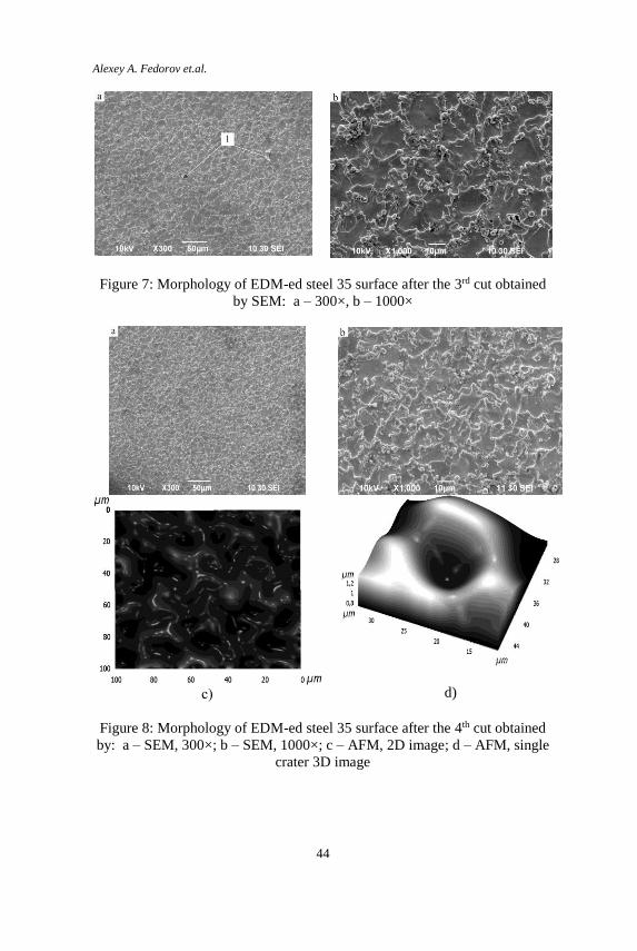
Figure 7: Morphology of EDM-ed steel 35 surface after the 3rd cut obtained
by SEM: a – 300×, b – 1000×
с)
d)
Figure 8: Morphology of EDM-ed steel 35 surface after the 4th cut obtained
by: a – SEM, 300×; b – SEM, 1000×; c – AFM, 2D image; d – AFM, single
crater 3D image

The Influence of Steel 35 Wire EDM Parameters on The Surface Roughness and Morphology
45
The fourth cut provided the smoothest surface (Figure 8a, 8b). Stuck
EDM debris is not observed. The size of a single crater is 12.5 - 13µm. It is
necessary to note that the overall relief look is the similar after the 3rd and the
4th cuts, but craters sizes and Ra parameter values differs much (Figure 4c -
4d and Table 2). Atomic force microscopy of surface and a single crater after
the fourth cut (Figure 8c, 8d), and the scanning electronic microscopy result
is proved (Figure 8a, 8b). Particularly, it can be noted, that a single crater is
surrounded by bulges formed by discharged metal laps.
Let us consider some more characteristics of the surface morphology. In particular, crater 1 shown in Figure 9a, seems to be interesting for this
research. More carefully studying was on this area after 7500× magnification
(Figure 9b).
Figure 9: Morphology features on steel 35 surface after wire EDM: a –
abnormal crater area, one cut, 1000×; b – abnormal crater area, one cut,
7500×
It was noted that the crater boundaries have coral-like relief 1, while
the crater bottom has a profile made of spikes 2 with 0.5-1 µm length and
about 100-200 nm thickness, looking like martencite plates, it is necessary to
note that such microstructures have never been described before by scientists
working in the sphere of EDM. The describing of their occurrence process is
rather difficult nowadays. However, we suppose that the crater itself
appeared after the single impulse, which is much stronger in its electric
parameters than a working mode average impulse. The spikes are a result of
fast cooling of metal micro volume under high pressure. Below is our view
on the mechanism of this area formation. Today, material scientists already
describe the mechanism of martensite plates forming: if steel cooling rate ν
after high temperatures (higher than the A3 point) becomes higher than
critical cooling rate νcr, decomposition of austenite into ferritic-cementitic
mixture is suppressed, and austenite experiences martensitic transformation.
Point A3 is equal to 810° C for steel 35. As known from the wire EDM
process physics, plasma channel temperature can reach 5000° К or more,

Alexey A. Fedorov et.al.
46
which is much higher than A3 point that is why metal starts melting and even
evaporating. Under the melted metal zone, there is an area, heated higher
than A3 (Figure 10).
Figure 10: Position of heated higher then A3 zone
A part of the top layer evaporates while the melted part is spurtled
from the crater and taken away by the flushed fluid stream. At this moment,
the area heated higher than A3 becomes open. Continuous flushing provides
not only the erosion by-products taking away but also required cooling rate
of the area heated higher than A3, i.e. condition ν> νcr is met. We have the
necessary set of conditions (heating higher than A3, followed by cooling) for
surpassing austenite decomposition into ferritic-cementitic mixture and its
martensite transformation.
As known from Nishiyama [9], martensite transformation does not
reach its end and that is why there is always retained austenite in steel,
possibly found between martensite plates (Figure 9b). It is also known from
Gulyaev [10] that in low-carbon and medium-carbon steels the martensite
plates width is 0.2-2 µm while its length should be 4-5 times bigger. This fact
corresponds well with the photos obtained in the given experiment.
Still, the following question seems to be interested: if such area is a
defect leading to strength, cracking resistance and other characteristics
decrease. However, verification of this idea is the object of an independent
research, in the future. In our opinion, it is possible, that this area is neutral
and does not have any negative effects. This crater does not have any positive
effect either, because such elements can be rarely found on the surface.
The results of the surface morphology analysis have shown, that the surface resulting after EDM (Figure 5-9) does not correspond to the
theoretical one (Figure 1c). In our opinion, there are two reasons for this. The
first reason is the fact that the idealized theoretical model does not account
for the formation of a gas bubble at each elementary act of removing
The Influence of Steel 35 Wire EDM Parameters on The Surface Roughness and Morphology
47
microscopic metal volume. It is known that the pressure in the gas bubble
may reach 20 GPa. It does not also account for the spreading of the gas
bubble front, which may have different effects on the molten metal micro
volume. Generally, the impact is reduced to the sticking of the molten metal to the craters surface and partial displacement of a certain volume of metal.
In addition, the theoretical modeling becomes even more complicated if we
try to consider the interaction of several gas bubbles fronts. Given that in 1 second a few hundred or even thousand of pulses
occur, the impact of gas bubbles at each other will definitely take place. The
second reason is that the theoretical model does not take into account the
counter flows of the pumped liquid. The pumped liquid is supplied from the
upper and lower nozzles. Having met in a narrow inter-electrode gap, the
flows form turbulent eddies, which in addition to the removal of sludge can
cause sticking to the surface. Finally, in our view, the most difficult situation
for modeling is the simultaneous effect of the two factors described above.
Besides the above, we can say that the actual surface shape mismatch
is caused by a variety of the single crater forms, which in its turn, is caused
by the anisotropy of the material being machined.
Conclusion
In conclusion, the present research has shown that the surface morphology
and roughness obtained during the research differs very much from the
theoretical one. The relief described in theory and consisting of closely
located craters is reached only after the third cut. At the same time, there is
no one crater with the round form on the surface under study. Zigzag lines
form all the craters boundaries. The size of the craters varies considerably,
too, and can double in size. We could suggest the following main reasons of
the difference between the theoretical model and the result obtained in
practice:
The presence of a gas bubble in every elementary displacement of
metal micro volume.
Turbulent eddies, formed by the flows of the pumped liquid.
Anisotropy of the material being machined.
Acknowledgements
The authors gratefully acknowledge the financial support provided to this
research by the Omsk State Technical University (OmSTU), under the
research work number 17033V

Alexey A. Fedorov et.al.
48
References [1] Lazarenko, B. R., and Lazarenko N. I., “Electric Spark Method for
Machining Metals”, Translated from Stanki i Instrument, Vol. 17,
(1946), and Vol. 18, (1947).
[2] Keskin, Y., Halkaci, H. S., & Kizil, M. (2006). “An experimental study
for determination of the effects of machining parameters on surface
roughness in electrical discharge machining (EDM)”. International
Journal for Advanced Manufacturing Technology, 28, 1118–1121.
http://doi.org/10.1007/s00170-004-2478-8
[3] B. R. Lazarenko and N. I. Lazarenko, “Technological characteristics of
electrospark machining of current conducting materials”. In B. R.
Lazarenko (ed.), Electrospark Machining of Metals, Vol. 2 (English
Transl.), Consultants Bureau, New York, (1964), pp. 7 - a.
[4] Ho, K. H., Newman, S. T., Rahimifard, S., & Allen, R. D. (2004).
“State of the art in wire electrical discharge machining (WEDM)”.
International Journal of Machine Tools and Manufacture, 44(12-13),
1247–1259. http://doi.org/10.1016/j.ijmachtools.2004.04.017
[5] Y. Suziki, M. Kishi, “Improvement of Surface Roughness in wire
EDM”, Proceedings of the Ninth International Symposium for Electro-
Machining (ISEM-9), Nagoya, Japan, (1989).
[6] N. Tosun, C. Cogun, A. Inan, “The effect of cutting parameters on
workpiece surface roughness in wire EDM”, Machining Sci. Technol. 7
(2) (2003) 209–219.
[7] Yang, X., Guo, J., Chen, X., & Kunieda, M. (2011). “Molecular
dynamics simulation of the material removal mechanism in micro-
EDM”. Precision Engineering, 35(1), 51–57.
http://doi.org/10.1016/j.precisioneng.2010.09.005
[8] Serebrenitsky, P.P., (2013). “Sovremennye elektroerozionnye
tekhnologii i oborudovaniye”, second ed. Lan, Sankt-Petersburg, pp.
11-13. (in Russian)
[9] Nishiyama, Z., (1978). “Martensitic transformation”. Academic press,
New York, vol. 1,2
[10] Gulyaev, A.P., (1986). “Metallovedeniye”, sixth ed. Metallurgiya,
Moscow, p.233 (in Russian